doi: ijesmr i e sciences & management r
TRANSCRIPT

[Ganguly *, 6(9): September, 2019] ISSN 2349-6193
DOI: 10.5281/zenodo.3346011 Impact Factor: 3.866
IJESMR International Journal of Engineering Sciences & Management Research
http: // © International Journal of Engineering Sciences & Management Research
[1]
USE OF PLASTIC INSERTS FOR MANUFACTURING OF INTERNAL CAVITY IN
POWDER METALLURGY Gunarnab Ganguly
Under the guidance of Prof. S.D. Lembe
Department of Production Engineering, Bharati Vidyapeeth (Deemed to Be University) College of
Engineering, Pune-411 043 (India)
ABSTRACT Powder metallurgy technology requires maximum simplification of the shape of components which has a
considerable effect on the design of the press mold, determining the production costs of the process as a whole,
especially under the conditions of individual and small-series production. Powder metallurgy technology
requires maximum simplification of the shape of components which has a considerable effect on the design of
the press mold, determining the production costs of the process as a whole, especially under the conditions of
individual and small-series production.
Some types of components cannot be produced using conventional press molds designed usually for multiple
application. In particular, they include components containing cavities of relatively complicated configuration-
with projections, pockets, expansion of the volume, etc. Cavities of this type are produced using removable
inserts.
INTRODUCTION Powder metallurgy is a term covering a wide range of ways in which materials or components are made from
metal powders. PM processes can avoid, or greatly reduce, the need to use metal removal processes, thereby
drastically reducing yield losses in manufacture and often resulting in lower costs.
Powder metallurgy is also used to make unique materials impossible to get from melting or forming in other
ways. A very important product of this type is tungsten carbide. WC is used to cut and form other metals and is
made from WC particles bonded with cobalt. It is very widely used in industry for tools of many types and
globally ~50,000t/yr is made by PM. Other products include sintered filters, porous oil-impregnated bearings,
electrical contacts and diamond tools.
Since the advent of industrial production–scale metal powder–based additive manufacturing (AM) in the
2010s, selective laser sintering and other metal AM processes are a new category of commercially important
powder metallurgy applications.
Iron powder is commonly used for sintering
The PM press and sinter process generally consists of three basic steps: powder blending (pulverisation), die
compaction, and sintering. Compaction is generally performed at room temperature, and the elevated-
temperature process of sintering is usually conducted at atmospheric pressure and under carefully controlled
atmosphere composition. Optional secondary processing such as coining or heat treatment often follows to
obtain special properties or enhanced precision.

[Ganguly *, 6(9): September, 2019] ISSN 2349-6193
DOI: 10.5281/zenodo.3346011 Impact Factor: 3.866
IJESMR International Journal of Engineering Sciences & Management Research
http: // © International Journal of Engineering Sciences & Management Research
[2]
One of the older such methods, and still one used to make around 1Mt/yr of structural components of iron-based
alloys, is the process of blending fine (<180 microns) metal (normally iron) powders with additives such as a
lubricant wax, carbon, copper, and/or nickel, pressing them into a die of the desired shape, and then heating the
compressed material ("green part") in a controlled atmosphere to bond the material by sintering. This produces
precise parts, normally very close to the die dimensions, but with 5-15% porosity, and thus sub-wrought steel
properties.
There are several other PM processes which have been developed over the last fifty years. These include:
Powder forging. A "preform" made by the conventional "press and sinter" method is heated and then hot
forged to full density, resulting in practically as-wrought properties.
Hot isostatic pressing (HIP). Here the powder (normally gas atomized, spherical type) is filled into a
mould, normally consisting of a metallic "can" of suitable shape. The can is vibrated, then evacuated and
sealed. It is then placed in a hot isostatic press, where it is heated to a homologous temperature of around
0.7, and subjected to an external gas pressure of ~100MPa (1000bar, 15,000psi) for 10-100minutes. This
results in a shaped part of full density with as-wrought or better, properties. HIP was invented in the 1950-
60s and entered tonnage production in the 1970-80s. In 2015, it was used to produce ~25,000t/yr of
stainless and tool steels, as well as important parts of superalloys for jet engines.
Metal injection moulding (MIM). Here the powder, normally very fine (<25microns) and spherical, is
mixed with plastic or wax binder to near the maximum solid loading, typically around 65vol%, and
injection moulded to form a "green" part of complex geometry. This part is then heated or otherwise treated
to remove the binder (debinding) to give a "brown" part. This part is then sintered, and shrinks by ~18% to
give a complex and 97-99% dense finished part. Invented in the 1970s, production has increased since 2000
with an estimated global volume in 2014 of 12,000t worth €1265millions.
Electric current assisted sintering (ECAS) technologies rely on electric currents to densify powders, with
the advantage of reducing production time dramatically (from 15 minutes of the slowest ECAS to a few
microseconds of the fastest), not requiring a long furnace heat and allowing near theoretical densities but
with the drawback of simple shapes. Powders employed in ECAS can avoid binders thanks to the
possibility of direct sintering, without the need of pre-pressing and a green compact. Molds are designed for
the final part shape since the powders densify while filling the cavity under an applied pressure thus
avoiding the problem of shape variations caused by non isotropic sintering and distortions caused by
gravity at high temperatures. The most common of these technologies is hot pressing, which has been under
use for the production of the diamond tools employed in the construction industry. Spark plasma
sintering and electro sinter forging are two modern, industrial commercial ECAS technologies.
Additive manufacturing (AM) is a relatively novel family of techniques which use metal powders (among
other materials, such as plastics) to make parts by laser sintering or melting. This is a process under rapid
development as of 2015, and whether to classify it as a PM process is perhaps uncertain at this stage.
Processes include 3D printing, selective laser sintering (SLS), selective laser melting (SLM), and electron
beam melting (EBM).
LITERATURE REVIEW
Powder metallurgy
Powder metallurgy (PM) is a metal working process for forming precision metal components from metal
powders. The metal powder is first pressed into product shape at room temperature. This is followed by heating
(sintering) that causes the powder particles to fuse together without melting.
The parts produced by PM have adequate physical and mechanical properties while completely meeting the
functional performance characteristics. The cost of producing a component of given shape and the required
dimensional tolerances by PM is generally lower than the cost of casting or making it as a wrought product,
because of extremely low scrap and the fewer processing steps. The cost advantage is the main reason for
selecting PM as a process of production for high – volume component which needs to be produced exactly to, or
close to, final dimensions. Parts can be produced which are impregnated with oil or plastic, or infiltrated with
lower melting point metal. They can be electroplated, heat treated, and machined if necessary.

[Ganguly *, 6(9): September, 2019] ISSN 2349-6193
DOI: 10.5281/zenodo.3346011 Impact Factor: 3.866
IJESMR International Journal of Engineering Sciences & Management Research
http: // © International Journal of Engineering Sciences & Management Research
[3]
The rate of production of parts is quite high, a few hundred to several thousand per hour. Industrial applications
of PM parts are several. These include self – lubricating bearings, porous metal filters and a wide range of
engineered shapes, such as gears, cams, brackets, sprockets, etc.
2.1. Process Details:
In the PM process the following three steps are followed in sequence: mixing (or blending), compacting, and
sintering.
Mixing: A homogeneous mixture of elemental metal powders or alloy powders is prepared. Depending upon the
need, powders of other alloys or lubricants may be added.
Compacting: A controlled amount of the mixed powder is introduced into a precision die and then it is pressed
or compacted at a pressure in the range 100 MPa to 1000 MPa. The compacting pressure required depends on
the characteristics and shape of the particles, the method of mixing, and on the lubricant used. This is generally
done at room temperature. In doing so, the loose powder is consolidated and densified into a shaped model. The
model is generally called “green compact.” As is comes out of the die, the compact has the size and shape of the
finished product. The strength of the compact is just sufficient for in – process handling and transportation to the
sintering furnace.
Fig.1 Typical set of powder metallurgy tools
To illustrate the process, let us take a straight cylindrical part such as a sleeve bearing. Fig.1 shows a typical set
of tools used for producing this part. The compacting cycle for this part (Fig.2) follows the following steps.

[Ganguly *, 6(9): September, 2019] ISSN 2349-6193
DOI: 10.5281/zenodo.3346011 Impact Factor: 3.866
IJESMR International Journal of Engineering Sciences & Management Research
http: // © International Journal of Engineering Sciences & Management Research
[4]
Fig.2 Powder metallurgy compacting cycle
1. With the upper punch in the withdrawn position, the empty die cavity is filled with mixed powder.
2. The metal powder in the die is pressed by simultaneous movement of upper and lower punches.
3. The upper punch is withdrawn, and the green compact is ejected from the die by the lower punch.
4. The green compact is pushed out of the pressing area so that the next operating cycle can start.
This compacting cycle is almost the same for all parts.
Sintering: During this step, the green compact is heated in a protective atmosphere furnace to a suitable
temperature, which is below the melting point of the metal. Typical sintering atmospheres are endothermic gas,
exothermic gas, dissociated ammonia, hydrogen, and nitrogen. Sintering temperature varies from metal to metal;
typically these are within 70 to 90% of the melting point of the metal or alloy. Table 10.1 gives the sintering
temperatures used for various metals. Sintering time varies with size and metal of part. Table 10.1 also gives
typical range of sintering time needed for various metals.

[Ganguly *, 6(9): September, 2019] ISSN 2349-6193
DOI: 10.5281/zenodo.3346011 Impact Factor: 3.866
IJESMR International Journal of Engineering Sciences & Management Research
http: // © International Journal of Engineering Sciences & Management Research
[5]
Table.1 Sintering temperature and time for various metal powders
Material Temperature
(℃)
Time
Copper, brass, bronze
Nickel
Stainless steels
Ferrites
Tungsten carbide
Molybdenum
Tungsten
Tantalum
760-900
1000-1150
1100-1290
1200-1500
1430-1500
2050
2350
2400
10-40
30-40
30-60
10-600
20-30
120
480
480
Sintering is a solid state process which is responsible for producing physical and mechanical properties in the
PM part by developing metallurgical bond among the powder particles. It also serves to remove the lubricant
from the powder, prevents oxidation, and controls carbon content in the part. The structure and porosity
obtained in a sintered compact depend on the temperature, time, and processing details. It is not possible to
completely eliminate the porosity because voids cannot be completely closed by compaction and because gases
evolve during sintering. Porosity is an important characteristic for making PM bearings and filters.
2.2. Secondary and finishing operations
Sometimes additional operations are carried out on sintered PM parts in order to further improve their properties
or to impart special characteristics. Some important operations are as under.
1. Coining and sizing. These are high pressure compacting operations. Their main function is to impart
(a) greater dimensional accuracy to the sintered part, and (b) greater strength and better surface finish
by further densification.
2. Forging. The sintered PM parts may be hot or cold forged to obtain exact shape, good surface finish,
good dimensional tolerances, and a uniform and fine grain size. Forged PM parts are being increasingly
used for such applications as highly stressed automotive, jet – engine and turbine components.
3. Impregnation. The inherent porosity of PM parts is utilized by impregnating them with a fluid like oil
or grease. A typical application of this operation is for sintered bearings and bushings that are internally
lubricated with upto 30% oil by volume by simply immersing them in heated oil. Such components
have a continuous supply of lubricant by capillary action, during their use. Universal joint is a typical
grease – impregnated PM part.
4. Infiltration. The pores of sintered part are filled with some low melting point metal with the result that
part's hardness and tensile strength are improved. A slug of metal to be impregnated is kept in close
contact with the sintered component and together they are heated to the melting point of the slug. The
molten metal infiltrates the pores by capillary action. When the process is complete, the component has
greater density, hardness, and strength. Copper is often used for the infiltration of iron – base PM

[Ganguly *, 6(9): September, 2019] ISSN 2349-6193
DOI: 10.5281/zenodo.3346011 Impact Factor: 3.866
IJESMR International Journal of Engineering Sciences & Management Research
http: // © International Journal of Engineering Sciences & Management Research
[6]
components. Lead has also been used for infiltration of components like bushes for which lower
frictional characteristics are needed.
5. Heat Treatment. Sintered PM components may be heat treated for obtaining greater hardness or
strength in them.
6. Machining. The sintered component may be machined by turning, milling, drilling, threading,
grinding, etc. to obtain various geometric features.
7. Finishing. Almost all the commonly used finishing method are applicable to PM parts. Some of such
methods are plating, burnishing, coating, and colouring.
Plating. For improved appearance and resistance to wear and corrosion, the sintered compacts
may be plated by electroplating or other plating processes. To avoid penetration and
entrapment of plating solution in the pores of the part, an impregnation or infiltration
treatment is often necessary before plating. Copper, zinc, nickel, chromium, and cadmium
plating can be applied.
Burnishing. To work harden the surface or to improve the surface finish and dimensional
accuracy, burnishing may be done on PM parts. It is relatively easy to displace metal on PM
parts than on wrought parts because of surface porosity in PM parts.
Coating. PM sintered parts are more susceptible to environmental degradation than cast and
machined parts. This is because of inter – connected porosity in PM parts. Coatings fill in the
pores and seal the entire reactive surface.
Colouring. Ferrous PM parts can be applied colour for protection against corrosion. Several
methods are in use for colouring. One common method to blacken ferrous PM parts is to do it
chemically, using a salt bath.
8. Joining. PM parts can be welded by several conventional methods. Electric resistance welding is better
suited than oxy- acetylene welding and arc welding because of oxidation of the interior porosity. Argon
arc welding is suitable for stainless steel PM parts.
2.3. Advantages of powder metallurgy
1. Powder metallurgy produces near net shape components. The technique required few or no secondary
operations.
2. Parts of powder metallurgy can be produce from high melting point refractory metals with less cost
and difficulties.
3. The tolerance of components produced by this technique have quite high tolerance, therefore no
further machining is not required.
4. This technique involves high Production Rate along with low Unit Cost.
5. It can produce complicated forms with a uniform microstructure.
6. Powder metallurgy has full capacity for producing a variety of alloying systems and particulate
composites.
7. This technique has flexibilities for producing PM parts with specific physical and mechanical
properties like hardness, strength, density and porosity.
8. By using powder metallurgy, parts can be produced with infiltration and impregnation of other
materials to obtain special characteristics which are needed for specific application.
9. Powder metallurgy can be used to produce bi-metallic products, porous bearing and sintered carbide.
10. Powder metallurgy makes use of 100% raw material as no material is wasted as scrap during process.
2.4. Disadvantages of powder metallurgy
1. The production of powder for metallurgy is very high.
2. The products of metallurgy can have limited shapes and features.
3. This technique causes potential workforce health problems from atmospheric contamination of the
workplace.
4. The tooling and equipments require for powder metallurgy are very expensive, therefore becomes main
issue with low production volume.
5. It’s difficult to produce large and complex shaped parts with powder metallurgy.
6. The parts produce by powder metallurgy have low ductility and strength.

[Ganguly *, 6(9): September, 2019] ISSN 2349-6193
DOI: 10.5281/zenodo.3346011 Impact Factor: 3.866
IJESMR International Journal of Engineering Sciences & Management Research
http: // © International Journal of Engineering Sciences & Management Research
[7]
7. Finally divided powder like aluminium, magnesium, titanium and zirconium are fire hazard and
explosive in nature.
8. This technique is not useful for low melting powder such as zinc, cadmium and tin as they show
thermal difficulties during sintering operations.
2.5. Limitations of powder metallurgy
1. High cost of metal powders compared to the cost of raw material used for casting or forging a
component. A few powders are even difficult to store without some deterioration.
2. High cost of tooling and equipment. This is particularly a limitation when production volumes are
small.
3. Large or complex shaped parts are difficult to produce by PM process.
4. Parts have lower ductility and strength than those produced by forging.
5. Uniformly high – density products are difficult to produce.
6. Some powders (such as aluminum, magnesium, titanium and zirconium) in a finally divided state
present fire hazard and risk of explosion.
7. Low melting point metal powders (such as of zinc, tin, cadmium) give thermal difficulties during
sintering operation, as most oxides of these metals cannot be reduced at temperatures below the
melting point.
2.6. Applications of powder metallurgy
There is a great variety of machine components that are produced from metal powders, many of these are put to
use without any machining operation carried out on them. Following are some of the prominent PM Products.
Filters: Permanent metal powder filters have greater strength and shock resistance than ceramic filters.
Fiber metal filters, having porosity upto 95% and more, are used for filtering air and fluids. Such filters
find use in dehydration for filtering air and fluids. Such filters find use in dehydrators for diffusing
moisture – laden air around some drying agent such as silica gel, Fig 3.
Fig.3 Applications of powder metallurgy parts. Filiers can be used for diffusing or for separating
These filters find wide usage also in petrol / diesel engines for separating dirt and moisture from fuel system.
Metal powder filters are also used for arresting flame and attenuating sound.
Cutting Tools and Dies. Cemented carbide cutting tool inserts find extensive applications in machine
shops. These are produced by PM from tungsten carbide powder mixed with cobalt binder.

[Ganguly *, 6(9): September, 2019] ISSN 2349-6193
DOI: 10.5281/zenodo.3346011 Impact Factor: 3.866
IJESMR International Journal of Engineering Sciences & Management Research
http: // © International Journal of Engineering Sciences & Management Research
[8]
Machinery Parts. Several machinery parts including gears, bushes and bearings, sprockets, rotors are
made from metal powders mixed with sufficient graphite to give to product the desired carbon content.
The parts have nearly 20 percent porosity. The pores of the parts which are to rub against another
surface in their use, are impregnated with oil to promote quiet operation.
Bearing and Bushes. Bearing and bushes to be used with rotating parts are made from copper powder
mixed with graphite. In small quantities, lead or tin may also be added for obtaining better wear
resistance. After sintering, the bearings are sized and then impregnated with oil by vacuum treatment.
Porosity in the bearings may be as high as 40 percent of the volume. Other machinery parts made by
PM include clutch plates, brake drums, ball retainers and welding rods.
Magnets. Small magnets produced from different compositions of powders of iron, Aluminium, nickel
and cobalt have shown excellent performance, far superior to those cast.
Electrical Parts. The possibility of combining several metal powders and maintaining some
characteristics of each has promoted PM for production of electric contact parts. These parts are
required to have excellent electrical conductively, be wear resistant, and somewhat refractory. Several
combinations such as copper – tungsten, cobalt – tungsten, silver – tungsten, copper-nickel, and silver –
molybdenum have been used for production of these parts.
PROBLEM DEFINITION
Powder metallurgy
Science of producing metal powders and making finished /semifinished objects from mixed or alloyed powders
with or without the addition of nonmetallic constituents.
Fig.4
[Ganguly *, 6(9): September, 2019] ISSN 2349-6193
DOI: 10.5281/zenodo.3346011 Impact Factor: 3.866
IJESMR International Journal of Engineering Sciences & Management Research
http: // © International Journal of Engineering Sciences & Management Research
[9]
Steps in powder metallurgy:
Powder production, Compaction, Sintering, & Secondary operations
Powder production:
Raw materials => Powder; Powders can be pure elements, pre-alloyed powders Methods for making powders –
Atomization: Produces powders of both ferrous and non-ferrous powders like stainless steel, superalloys, Ti
alloy powders; Reduction of compounds: Production of iron, Cu, tungsten, molybdenum; Electrolysis: for
making Cu, iron, silver powders Powders along with additives are mixed using mixers Lubricants are added
prior to mixing to facilitate easy ejection of compact and to minimize wear of tools; Waxes, metallic stearates,
graphite etc. Powder characterization – size, flow, density, compressibility tests
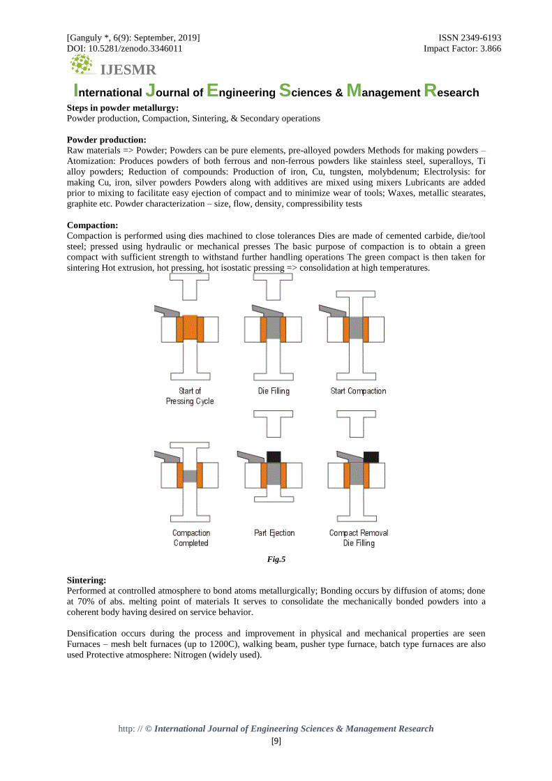
Compaction:
Compaction is performed using dies machined to close tolerances Dies are made of cemented carbide, die/tool
steel; pressed using hydraulic or mechanical presses The basic purpose of compaction is to obtain a green
compact with sufficient strength to withstand further handling operations The green compact is then taken for
sintering Hot extrusion, hot pressing, hot isostatic pressing => consolidation at high temperatures.
Fig.5
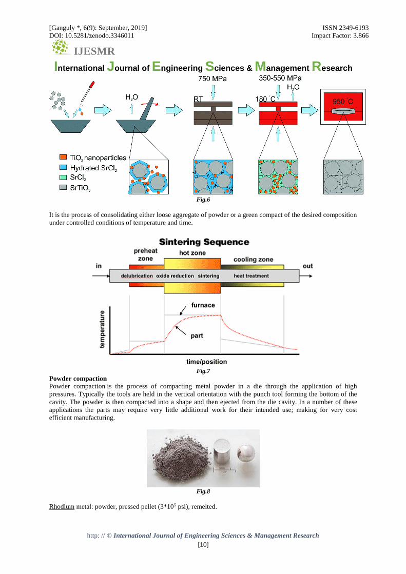
Sintering:
Performed at controlled atmosphere to bond atoms metallurgically; Bonding occurs by diffusion of atoms; done
at 70% of abs. melting point of materials It serves to consolidate the mechanically bonded powders into a
coherent body having desired on service behavior.
Densification occurs during the process and improvement in physical and mechanical properties are seen
Furnaces – mesh belt furnaces (up to 1200C), walking beam, pusher type furnace, batch type furnaces are also
used Protective atmosphere: Nitrogen (widely used).
[Ganguly *, 6(9): September, 2019] ISSN 2349-6193
DOI: 10.5281/zenodo.3346011 Impact Factor: 3.866
IJESMR International Journal of Engineering Sciences & Management Research
http: // © International Journal of Engineering Sciences & Management Research
[10]
Fig.6
It is the process of consolidating either loose aggregate of powder or a green compact of the desired composition
under controlled conditions of temperature and time.
Fig.7
Powder compaction
Powder compaction is the process of compacting metal powder in a die through the application of high
pressures. Typically the tools are held in the vertical orientation with the punch tool forming the bottom of the
cavity. The powder is then compacted into a shape and then ejected from the die cavity. In a number of these
applications the parts may require very little additional work for their intended use; making for very cost
efficient manufacturing.
Fig.8
Rhodium metal: powder, pressed pellet (3*105 psi), remelted.

[Ganguly *, 6(9): September, 2019] ISSN 2349-6193
DOI: 10.5281/zenodo.3346011 Impact Factor: 3.866
IJESMR International Journal of Engineering Sciences & Management Research
http: // © International Journal of Engineering Sciences & Management Research
[11]
EXPERIMENTATION / FABRICATION We conducted three experiments in this research paper and we got these results which is related to our
respective topic:-
Experiment no. 1
1.1 Pre-Required Material
1. Hydraulic Press.
2. A die of high carbon steel (EN 24) with two dowel pins. (Custom Designed Die)
3. Two Plungers.
4. Copper powder
5. Plastic insert (Acrylic)
Fig.9
1.2 Process
Firstly, we take the lower part of die and cover the lower part of die with the Plunger. Then we fill the required
amount of copper powder into the die. After that we close the die with the help of the upper part. By putting the
upper Plunger on the upper die, we made our setup ready for the experimentation. Then we switch on the
Hydraulic Press and put our setup in the machine for experimentation. After that we start increasing the load
gradually and suddenly we heard a noise after applying the load of 10kN and switch off the machine.

[Ganguly *, 6(9): September, 2019] ISSN 2349-6193
DOI: 10.5281/zenodo.3346011 Impact Factor: 3.866
IJESMR International Journal of Engineering Sciences & Management Research
http: // © International Journal of Engineering Sciences & Management Research
[12]
Fig.10
After taking out the setup form the machine we got semi open die because of that our plastic insert and required
product got broken.
Fig.11

[Ganguly *, 6(9): September, 2019] ISSN 2349-6193
DOI: 10.5281/zenodo.3346011 Impact Factor: 3.866
IJESMR International Journal of Engineering Sciences & Management Research
http: // © International Journal of Engineering Sciences & Management Research
[13]
1.3 Conclusion
Fig.12
In experiment no.1 we concluded that our die joining system is so weak and we need to improve that by making
some changes in the die.
Experiment no. 2
2.1 Pre-Required Material
1. Hydraulic Press.
2. A die of high carbon steel (EN 24) with Three dowel pins. (Custom Designed Die)
3. Two Plungers.
4. Copper powder
5. Plastic insert (Acrylic)
Fig.13
2.2 Process
In this experiment we made our setup exactly the same we did in last experiment the main change in our
customised die. We added one more dowel pin in our die to make the joining part more strong but after starting

[Ganguly *, 6(9): September, 2019] ISSN 2349-6193
DOI: 10.5281/zenodo.3346011 Impact Factor: 3.866
IJESMR International Journal of Engineering Sciences & Management Research
http: // © International Journal of Engineering Sciences & Management Research
[14]
the Hydraulic Press and after applying the load gradually again we heard the a noise and stop the machine after
applying the force of 18kN.
Fig.14
After taking out the setup form the machine we got semi open die because of that our plastic insert and required
product got broken.
Fig.15

[Ganguly *, 6(9): September, 2019] ISSN 2349-6193
DOI: 10.5281/zenodo.3346011 Impact Factor: 3.866
IJESMR International Journal of Engineering Sciences & Management Research
http: // © International Journal of Engineering Sciences & Management Research
[15]
2.3 Conclusion
In experiment no.2 we concluded that our die joining system is still weak and we need to improve that by
making some changes in the die.
Fig.16
Experiment no. 3
3.1 Pre-Required Material
1. Hydraulic Press.
2. A die of high carbon steel (EN 24) with two dowel pins and two threaded screws. (Custom Designed
Die)
3. Two Plungers.
4. Copper powder
5. Plastic insert (Acrylic)
Fig.17

[Ganguly *, 6(9): September, 2019] ISSN 2349-6193
DOI: 10.5281/zenodo.3346011 Impact Factor: 3.866
IJESMR International Journal of Engineering Sciences & Management Research
http: // © International Journal of Engineering Sciences & Management Research
[16]
3.2 Process
Firstly, we take the lower part of die and cover the lower part of die with the Plunger. Then we fill the required
amount of copper powder into the die. After that we close the die with the help of the upper part and tie both
screws of the die and it made our setup perfect. Then we switch on the Hydraulic Press and put our setup in the
machine for experimentation. After that we start increasing the load gradually, this time we didn’t heard any
noise and reach at 25kN load. After taking out the setup form the machine.
Fig.18
Finally we got the desired product of our choice, we got H shaped product and during sintering we got the
plastic insert melted and our product got hardened.
[Ganguly *, 6(9): September, 2019] ISSN 2349-6193
DOI: 10.5281/zenodo.3346011 Impact Factor: 3.866
IJESMR International Journal of Engineering Sciences & Management Research
http: // © International Journal of Engineering Sciences & Management Research
[17]
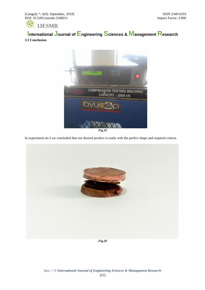
3.3 Conclusion
Fig.19
In experiment no.3 we concluded that our desired product is ready with the perfect shape and required criteria.
Fig.20

[Ganguly *, 6(9): September, 2019] ISSN 2349-6193
DOI: 10.5281/zenodo.3346011 Impact Factor: 3.866
IJESMR International Journal of Engineering Sciences & Management Research
http: // © International Journal of Engineering Sciences & Management Research
[18]
Fig.21
Fig.22
STATUS OF PROJECT With the help of our guide Prof. S. D. Lembe, our adequate knowledge of in manufacturing we are able to
manufacture a powder manufacturing component of copper powder (Micro) with grooves on it using our
specially designed die.
To create grooves in the powdered components the use of plastic inserts has turned out to be fruitful in the
creation of the groups on the product.

[Ganguly *, 6(9): September, 2019] ISSN 2349-6193
DOI: 10.5281/zenodo.3346011 Impact Factor: 3.866
IJESMR International Journal of Engineering Sciences & Management Research
http: // © International Journal of Engineering Sciences & Management Research
[19]
All the experiments carried out has proved to be successful in manufacturing Complex powder metallurgy
components.
FUTURE PLAN Following the success of manufacturing Complex powder metallurgy components using plastic inserts fitted
inside specially designed die. We are determined to look forward towards mass manufacturing processes for
similar powder metallurgy components.
We look forward to design more Complex dies along with specially design features allowing high
manufacturing rates in powdered metallurgy.
We plan on studying different metal powder and their combinations to understand the perfect sintering sequence
and calculate for different ranges of temperature to be maintained in the furnace during sintering.
Study about Polymers and other plastic components and their properties advantages and limitations to decide
which material will be the best fit for a chosen metal powder.
With the above studies make financial calculations:-
1. Equipment and cooling cost
2. Cost of raw material
3. Manufacturing cost
4. Cost of profit
In overall plans to make manufacturing of complex powder metallurgy components in mass production.
CONCLUSION Powder metallurgy is very widely used in industry for tools of many types and globally ~50,000t/yr is made by
this and we can use it in making very useful product which is widely using in industry these days. Since the
advent of industrial production–scale metal powder–based additive manufacturing (AM) in the 2010s, selective
laser sintering and other metal AM processes are a new category of commercially important powder metallurgy
applications.
This report include the manufacturing of internal cavity by LSLS and two experiments which justifies my point
very well. It also include the total information about powder metallurgy and its application. This report contains
present stage of powder metallurgy and all aspects my topic and what can be done in future , in this field also.
This report also include sintering , powder compacting , powder production and all related topics and
experiments. Main topic is use of plastic inserts for manufacturing of internal cavity in powder metallurgy
which contains all related essential aspects.
Through this project worked under guidance of Professor S.D. Lembe, we have successfully proved that with
the use of plastic inserts we can manufacture internal cavities in powder metallurgy components.
ACKNOWLEDGEMENT We greatly appreciate the support & the encouragement extended for this study of “USE OF PLASTIC
INSERTS FOR MANUFACTURING OF INTERNAL CAVITY IN POWDER METALLURGY” by my
guide Prof. S.D. LEMBE who responded promptly and enthusiastically to any requests despite their congested
schedules.
We thank our dearest parents who encouraged us to extend our reach. With their support and blessing we were
able to come this far.

[Ganguly *, 6(9): September, 2019] ISSN 2349-6193
DOI: 10.5281/zenodo.3346011 Impact Factor: 3.866
IJESMR International Journal of Engineering Sciences & Management Research
http: // © International Journal of Engineering Sciences & Management Research
[20]
REFERENCE 1. O. V. Roman and I. P. Gabrielov, A Handbook of Powder Metallurgy: Powders, Materials, Processes
[in Russian], Minsk
2. E. Takasi, "A method of shaping sintered components and equipment for compacting powder," Japan
Claim 2236203, published 9/19/90.
3. N. Mikio, "A method of injection shaping of metals using and inserts element," Japan Claim 387302,
published 4/12/91.
4. M. Tosio and J. Mikio, "A method of shaping powders," Japan Claim 3267302, published 11/28/91.
5. M. Feygin, "Apparatus and method for forming an integral object from laminations," USA Patent
4752352, published 9/21/88.
6. "A Method and apparatus for producing parts by selective sintering," USA Patent 4863538, published
9/5/89.
7. J. J. Beaman and C. R. Deckard, "Selective laser sintering with assisted powder handing," USA Patent
4938816, published 7/3/90.
8. D. I. Dourell, H. L. Marcus, J. W. Barlow, et al., "Multiple material systems for selective beam
sintering," USA Patent 4944817, published July 31, 90.
9. D. I. Dourell, H. L. Marcus, J. W. Barlow, and J. J. Bealman, "Selective laser sintering of metal and
ceramics," Int. J. Powder Met., 28, No.4, 369-381 (1992).
10. www.researchgate.net
11. Google Patent etc.