domain analysis modeling jan 2009 wgm
TRANSCRIPT
Domain Analysis ModelingDomain Analysis Modeling
Abdul-Malik ShakirPrincipal Consultant, Shakir Consulting
January 2009 Working Group Meeting
Lake Buena Vista, FL
January 2009 Domain Analysis Modeling Tutorial 2 of 84
About Me
Abdul-Malik ShakirPrincipal Consultant, Shakir Consulting, La Verne, CA
HL7 Member since 1991
• Principal Consultant with Shakir Consulting
• Co-Chair of the HL7 Education Committee
• Member of the HL7 Architectural Review Board
• Member of the HL7 Public Health and Emergency Response Committee
• Member of the HL7 Regulated Clinical Research Information Management Committee
• Member of the HL7 Modeling and Methodology Committee
January 2009 Domain Analysis Modeling Tutorial 3 of 84
HL7 Development Framework
January 2009 Domain Analysis Modeling Tutorial 4 of 84
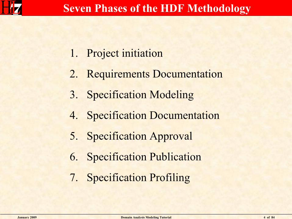
Seven Phases of the HDF Methodology
1. Project initiation
2. Requirements Documentation
3. Specification Modeling
4. Specification Documentation
5. Specification Approval
6. Specification Publication
7. Specification Profiling
January 2009 Domain Analysis Modeling Tutorial 5 of 84
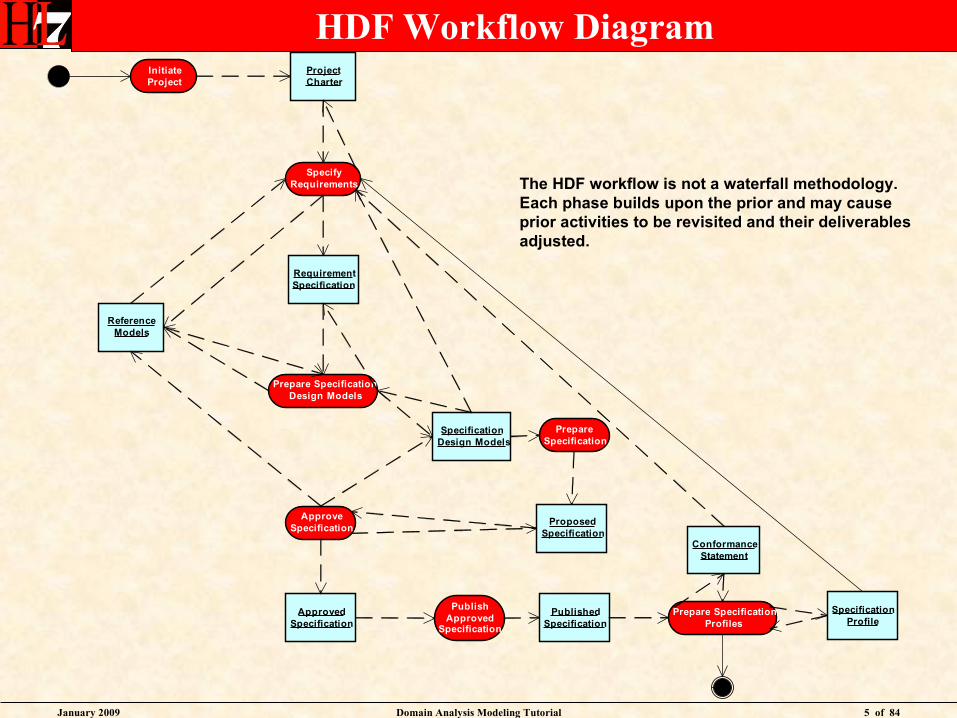
HDF Workflow DiagramInitiateProject
ProjectCharter
SpecifyRequirements
ReferenceModels
RequirementSpecification
Prepare SpecificationDesign Models
SpecificationDesign Models
PrepareSpecification
ApproveSpecification
ApprovedSpecification
PublishApproved
Specification
PublishedSpecification
Prepare SpecificationProfiles
SpecificationProfile
ConformanceStatement
ProposedSpecification
The HDF workflow is not a waterfall methodology.Each phase builds upon the prior and may causeprior activities to be revisited and their deliverablesadjusted.
January 2009 Domain Analysis Modeling Tutorial 6 of 84
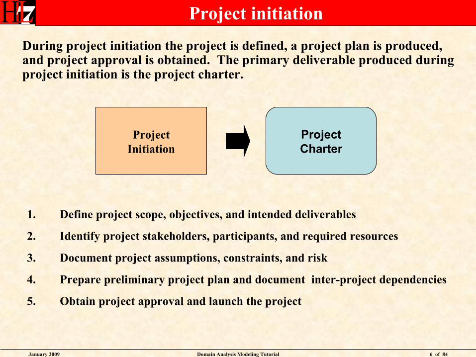
Project initiation
During project initiation the project is defined, a project plan is produced, and project approval is obtained. The primary deliverable produced during project initiation is the project charter.
ProjectInitiation
ProjectCharter
1. Define project scope, objectives, and intended deliverables
2. Identify project stakeholders, participants, and required resources
3. Document project assumptions, constraints, and risk
4. Prepare preliminary project plan and document inter-project dependencies
5. Obtain project approval and launch the project
January 2009 Domain Analysis Modeling Tutorial 7 of 84
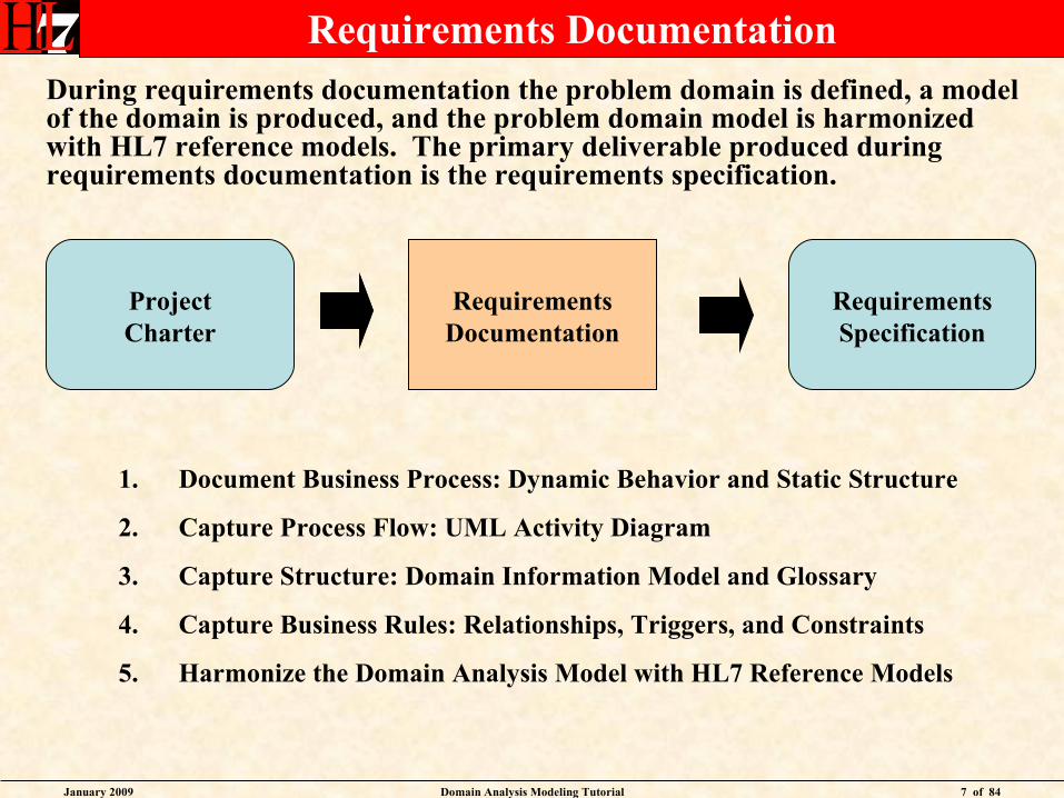
Requirements DocumentationDuring requirements documentation the problem domain is defined, a model of the domain is produced, and the problem domain model is harmonized with HL7 reference models. The primary deliverable produced during requirements documentation is the requirements specification.
RequirementsDocumentation
Requirements Specification
1. Document Business Process: Dynamic Behavior and Static Structure
2. Capture Process Flow: UML Activity Diagram
3. Capture Structure: Domain Information Model and Glossary
4. Capture Business Rules: Relationships, Triggers, and Constraints
5. Harmonize the Domain Analysis Model with HL7 Reference Models
ProjectCharter
January 2009 Domain Analysis Modeling Tutorial 8 of 84
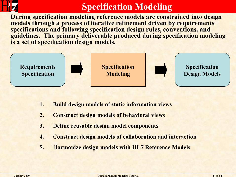
Specification ModelingDuring specification modeling reference models are constrained into design models through a process of iterative refinement driven by requirements specifications and following specification design rules, conventions, and guidelines. The primary deliverable produced during specification modeling is a set of specification design models.
SpecificationModeling
SpecificationDesign Models
1. Build design models of static information views
2. Construct design models of behavioral views
3. Define reusable design model components
4. Construct design models of collaboration and interaction
5. Harmonize design models with HL7 Reference Models
RequirementsSpecification
January 2009 Domain Analysis Modeling Tutorial 9 of 84
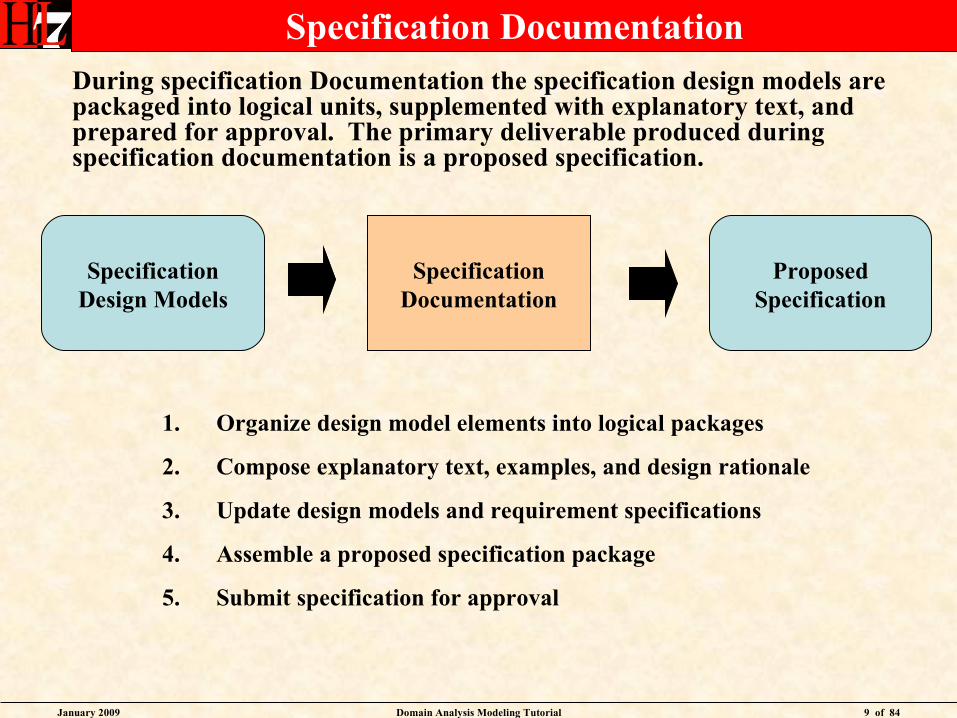
Specification DocumentationDuring specification Documentation the specification design models are packaged into logical units, supplemented with explanatory text, and prepared for approval. The primary deliverable produced during specification documentation is a proposed specification.
SpecificationDocumentation
ProposedSpecification
1. Organize design model elements into logical packages
2. Compose explanatory text, examples, and design rationale
3. Update design models and requirement specifications
4. Assemble a proposed specification package
5. Submit specification for approval
SpecificationDesign Models
January 2009 Domain Analysis Modeling Tutorial 10 of 84
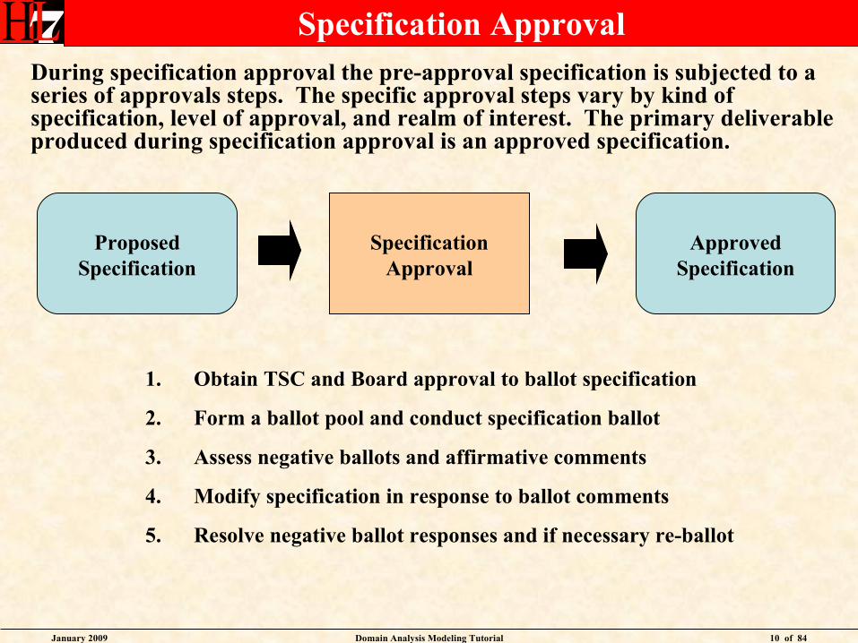
Specification ApprovalDuring specification approval the pre-approval specification is subjected to a series of approvals steps. The specific approval steps vary by kind of specification, level of approval, and realm of interest. The primary deliverable produced during specification approval is an approved specification.
SpecificationApproval
ApprovedSpecification
1. Obtain TSC and Board approval to ballot specification
2. Form a ballot pool and conduct specification ballot
3. Assess negative ballots and affirmative comments
4. Modify specification in response to ballot comments
5. Resolve negative ballot responses and if necessary re-ballot
ProposedSpecification
January 2009 Domain Analysis Modeling Tutorial 11 of 84
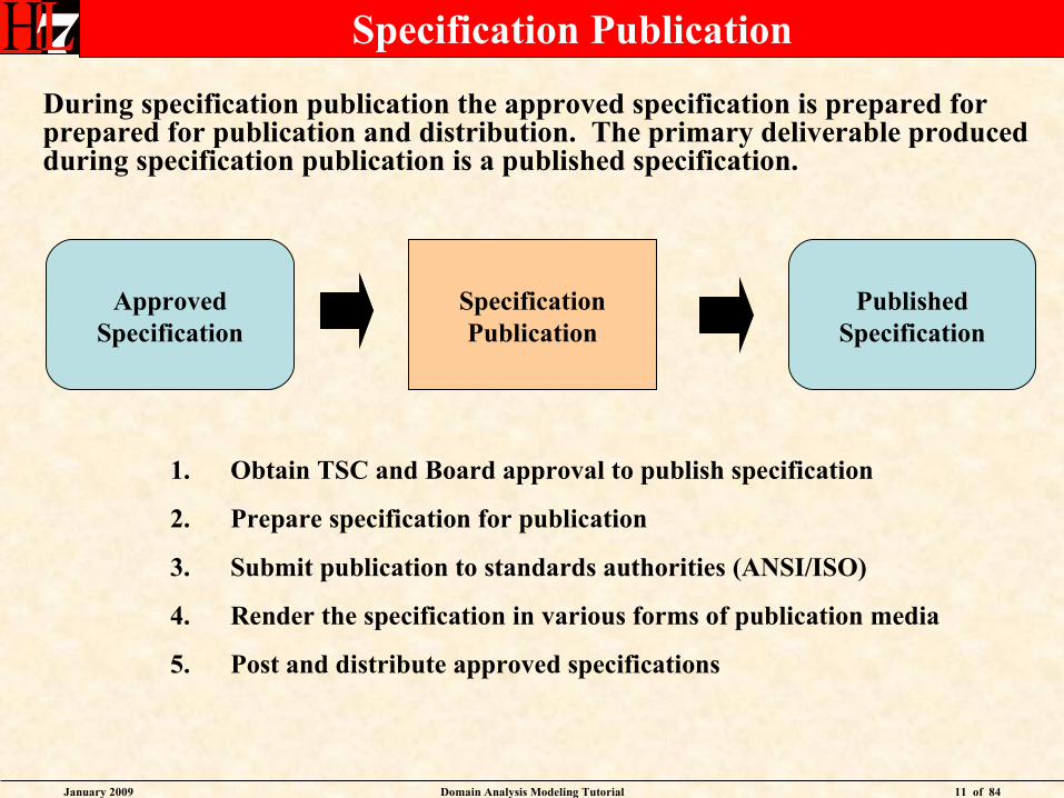
Specification Publication
During specification publication the approved specification is prepared for prepared for publication and distribution. The primary deliverable produced during specification publication is a published specification.
SpecificationPublication
PublishedSpecification
1. Obtain TSC and Board approval to publish specification
2. Prepare specification for publication
3. Submit publication to standards authorities (ANSI/ISO)
4. Render the specification in various forms of publication media
5. Post and distribute approved specifications
ApprovedSpecification
January 2009 Domain Analysis Modeling Tutorial 12 of 84
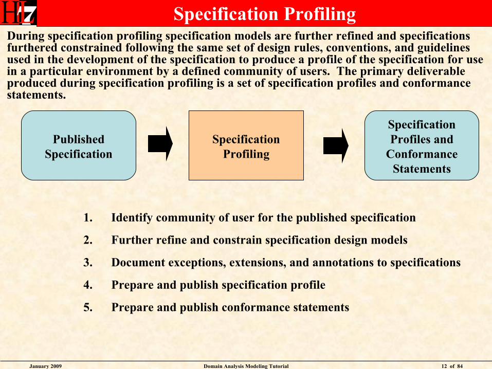
Specification ProfilingDuring specification profiling specification models are further refined and specifications furthered constrained following the same set of design rules, conventions, and guidelines used in the development of the specification to produce a profile of the specification for use in a particular environment by a defined community of users. The primary deliverable produced during specification profiling is a set of specification profiles and conformance statements.
SpecificationProfiling
SpecificationProfiles and
ConformanceStatements
1. Identify community of user for the published specification
2. Further refine and constrain specification design models
3. Document exceptions, extensions, and annotations to specifications
4. Prepare and publish specification profile
5. Prepare and publish conformance statements
PublishedSpecification
January 2009 Domain Analysis Modeling Tutorial 13 of 84
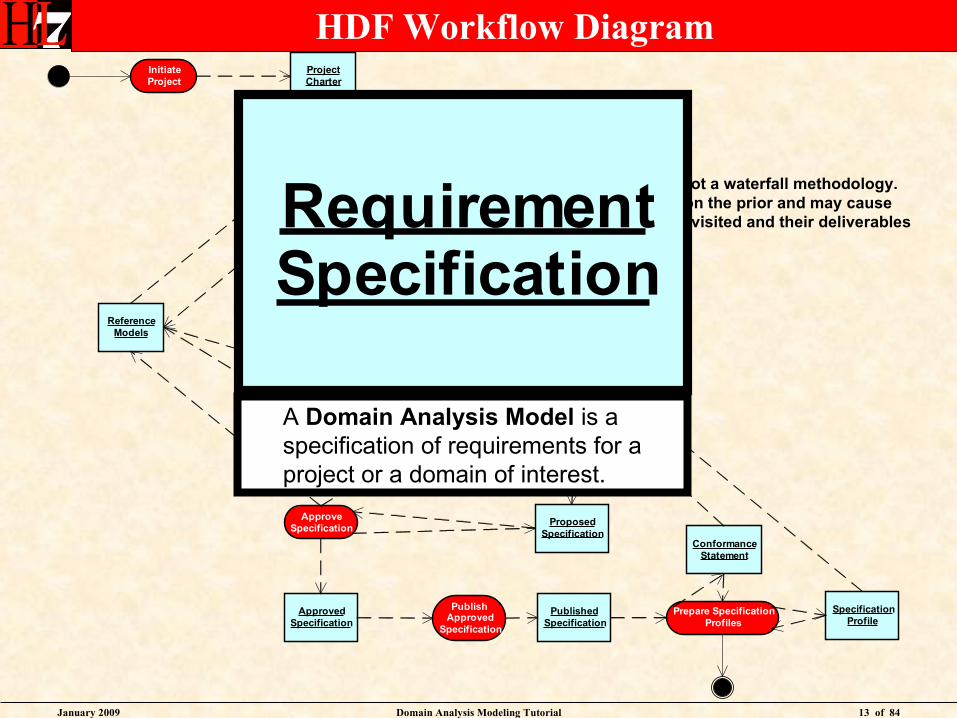
HDF Workflow DiagramInitiateProject
ProjectCharter
SpecifyRequirements
ReferenceModels
RequirementSpecification
Prepare SpecificationDesign Models
SpecificationDesign Models
PrepareSpecification
ApproveSpecification
ApprovedSpecification
PublishApproved
Specification
PublishedSpecification
Prepare SpecificationProfiles
SpecificationProfile
ConformanceStatement
ProposedSpecification
The HDF workflow is not a waterfall methodology.Each phase builds upon the prior and may causeprior activities to be revisited and their deliverablesadjusted.
RequirementSpecification
RequirementSpecification
A Domain Analysis Model is a specification of requirements for a project or a domain of interest.
January 2009 Domain Analysis Modeling Tutorial 14 of 84
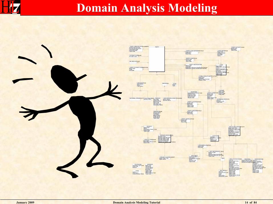
Domain Analysis Modeling
TEST RESULTAmountAmount Unit CodeCodeDateDescriptionDescription Code
PARTY
LOCATIONAddressIdentification NumberNameSetting CodeType Code
SPECIMENCollection DateDescriptionIdentification NumberNameSource CodeType Code
HEALTH RELATED ACTIVITYBegin Date TimeDisposition Date TimeDisposition DescriptionEnd DateIdentification NumberNotification IndicatorPriority CodeSource Type CodeType Code
HEALTH STATUS INQUIRYAmountAmount Unit CodeBegin DateDescriptionDescription CodeDurationDuration Unit CodeEnd DateLive Births NumberManufacturer Lot NumberManufacturer NameReason TextResult DateResult TextStatus CodeStatus DateTravel Country NameType Code
DIAGNOSISClassification Scheme CodeDisease CodeDiagnosis CodeDiagnosis DateSource CodeSource Text
PUBLIC HEALTH NOTIFICATIONBegin DateEnd DateIdentification NumberReason Code
INTERVENTIONAmountAmount NumberAmount Unit CodeDescriptionDurationDuration Unit CodeEnrollment CodeEnrollment Type CodeManufacturer Lot NumberManufacturer NameNameRoute CodeStatus CodeStatus Date
REFERRALReferral Basis CodeReferral Type NameReferral Acceptance Code
BILLING ACCOUNT
PARTY TO PARTY ASSOCIATIONBegin DateCodeEnd Date
CASE DEFINITIONBegin DateCategory CodeDescriptionEnd DateName
PARTY CONDITIONBegin DateDescriptionEnd DateNameName Status TextStatus Date
PARTY NOTIFICATIONBegin DateEnd DateNotification Receiver Identification NumberNotification Sender Identification Number
PARTY ACTIVITY ROLEBegin DateEnd DateRole Code
DISEASE CAUSING AGENTAgent Type CodeAgent Name
PARTY CASE ROLEBegin DateEnd DateRole Code
PARTY CASE DEFINITION ROLEBegin DateEnd DateRole Code
PARTY LOCATION ROLEBegin DateEnd DateRole CodeStatus CodeStatus Date
TEST
DISEASE ASSOCIATIONDisease CodeDisease Imported CodeEtiologic Status CodeEtiologic Status DateExposure Begin DateExposure End DateInfection (or Illness) Type Code(s)
SPECIMEN LOCATIONBegin DateEnd Date
PERSON NAMEDegree NameFirst NameLast NameMiddle NamePrefix NameSuffix NameType Code
PATIENT COVERAGEProvider Code
VEHICLEDescriptionName(Implication) Status CodeStatus DateType Code
CASEBegin DateConfirmation Method CodeCountCount Type CodeDetection Method CodeEnd DateIdentification NumberTransmission Mode CodeStatus CodeStatus Date
ADDRESSBegin DateCity NameCountry NameCounty NameEnd DatePostal CodeStatus DateState CodeStreet Address TextType Code
TELEPHONETelephone Type CodeArea CodeNumber
CODECodeDescriptionCoding System Name
ORGANIZATIONAlias NameNameType Code
EntityNameType
INDIVIDUAL
PERSONBirth DateDeath DateEthnicity CodeRace CodeSex CodeSoundex TextOccupation Name
NON PERSON LIVING ORGANISMGenus NameSpecies Name
INFORMAL ORGANIZATIONFormal OrganizationIndustry Code
PARTY IDENTIFICATION NUMBERIdentification NumberIssuing Authority NameIssue Begin DateIssue End DateType Code
TEST REFERENCE TABLEMethod CodeNameSamples Required NumberSamples Required Unit CodeType Code
PARTY SPECIMEN ROLEBegin DateEnd DateRole Code
PARTY VEHICLE ROLEBegin DateEnd DateRole Code
OUTBREAK STATISTICAmountCategory CodeType Code
VEHICLE CONDITIONDescriptionDescription Status CodeStatus Date
OutbreakBegin DateEnd DateExtent CodePeak Date
January 2009 Domain Analysis Modeling Tutorial 15 of 84
What is a Domain Analysis Model
• A domain analysis model is documentation of stakeholders, activities, interactions, and information for a particular domain of interest.
• A domain analysis model provides context for development of HL7 specifications by documenting specification requirements from a variety of subject matter expert perspectives.
• HL7 specification designs are intended to fulfill the behavioral, interaction and informational requirements documented in domain analysis models.
January 2009 Domain Analysis Modeling Tutorial 16 of 84
Why Model
• To aid in understanding relevant functions and information of a particular domain
• To communicate the modeler’s understanding of the domain and allow that understanding to be assessed by others
• To aid in reconciling multiple perspectives of a domain by combining varying perspectives into a single specification
• To document a solution design (existing or planned) so that the design may be evaluated
January 2009 Domain Analysis Modeling Tutorial 17 of 84
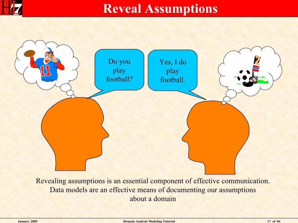
Revealing assumptions is an essential component of effective communication.Data models are an effective means of documenting our assumptions
about a domain
Yes, I doplay
football.
Do youplay
football?
Reveal Assumptions
January 2009 Domain Analysis Modeling Tutorial 18 of 84
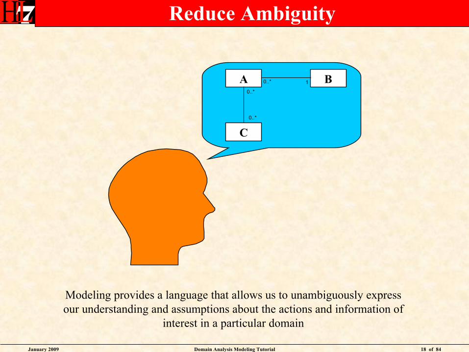
Modeling provides a language that allows us to unambiguously express our understanding and assumptions about the actions and information of
interest in a particular domain
Reduce Ambiguity
A
C
B
0..*
0..*
0..* 1
January 2009 Domain Analysis Modeling Tutorial 19 of 84
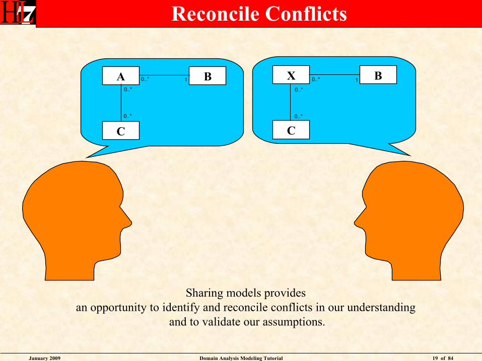
Sharing models provides an opportunity to identify and reconcile conflicts in our understanding
and to validate our assumptions.
Reconcile Conflicts
A
C
B
0..*
0..*
0..* 1 X
C
B
0..*
0..*
0..* 1
January 2009 Domain Analysis Modeling Tutorial 20 of 84
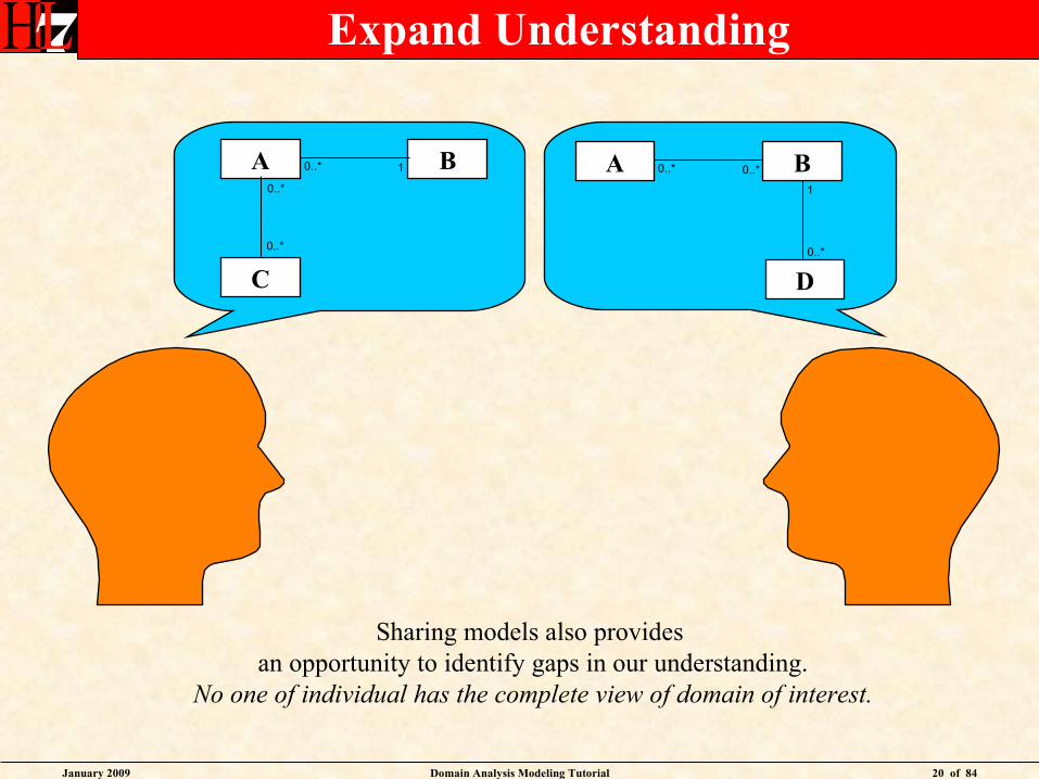
Sharing models also provides an opportunity to identify gaps in our understanding.
No one of individual has the complete view of domain of interest.
Expand Understanding
A
C
B
0..*
0..*
0..* 1
D
A B0..* 0..*
0..*
1
January 2009 Domain Analysis Modeling Tutorial 21 of 84
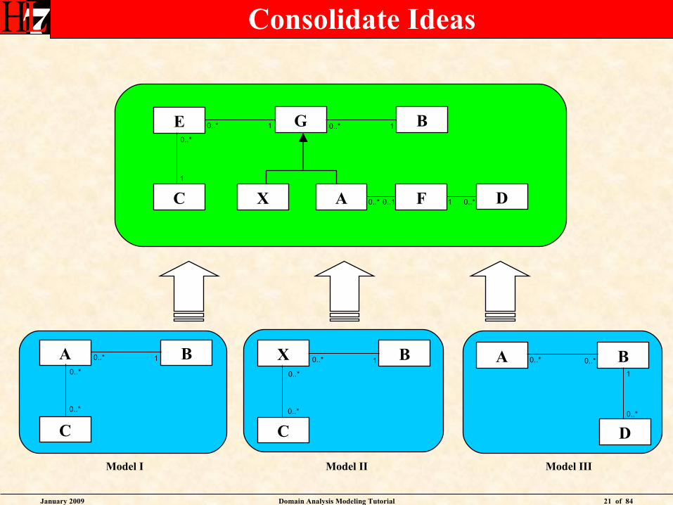
Consolidate Ideas
Model I Model II Model III
B
X F
E
C A D
G
1
0..*
0..* 1 0..* 1
0..* 0..1 0..*1
A
C
B
0..*
0..*
0..* 1 X
C
B
0..*
0..*
0..* 1
D
A B0..* 0..*
0..*
1
January 2009 Domain Analysis Modeling Tutorial 22 of 84
Value of Modeling
• Reveal Assumptions
• Reduce Ambiguity
• Reconcile Conflicts
• Expand Understanding
• Consolidate Ideas
January 2009 Domain Analysis Modeling Tutorial 23 of 84
Unified Modeling Language
• The HDF does not prescribe a particular modeling notation or methodology.
• The preferred modeling notation is the Unified Modeling Language (UML).
• UML is a modeling notation not a methodology.
• UML is used with multiple development methodologies such as Agile Processes and Rational Unified Process (RUP).
• The HDF is methodology neutral, as is the recommended UML notation.
January 2009 Domain Analysis Modeling Tutorial 24 of 84
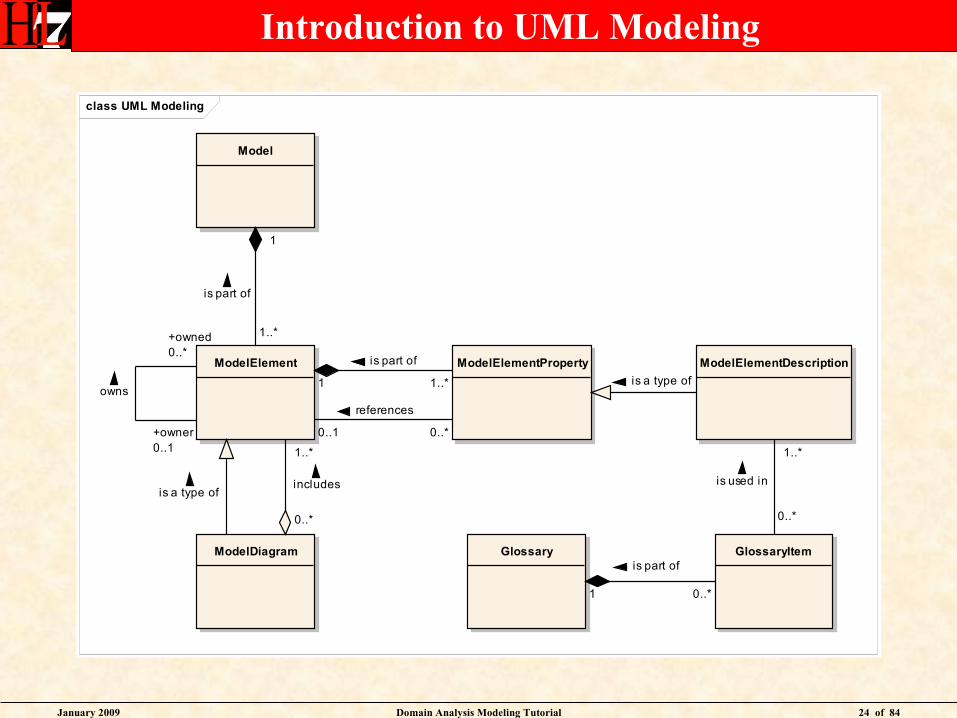
Introduction to UML Modeling
class UML Modeling
Model
ModelElement ModelElementProperty ModelElementDescription
Glossary GlossaryItemModelDiagram
1..*
is part of
1
1..*
is part of
1
is a type of
1..*
includes
0..*
is a type of
0..*
is part of
1
1..*
is used in
0..*
0..*
references
0..1
+owned0..*
owns
+owner0..1

January 2009 Domain Analysis Modeling Tutorial 25 of 84
Introduction to UML Modeling
• A Model always is composed of one or more Model Element
• A Model Element always is part of one Model
• A Model Element always is composed of one or more Model Element Property
• A Model Element Property always is part of one Model Element
• A Model Element Property sometimes references one Model Element
• A Model Element sometimes is referenced by one or more Model Element Property
• A Model Element Description always is a type of one Model Element Property
• A Glossary sometimes is composed of one or more Glossary Item
• A Glossary Item always is part of one Glossary
• A Glossary Item always is used in one or more Model Element Description
• A Model Element Description sometimes uses one or more Glossary Item
• A Model Element sometimes owns one or more Model Element
• A Model Element sometimes is owned by one Model Element
• A Model Diagram always is a type of one Model Element
• A Model Diagram always includes one or more Model Element
• A Model Element sometimes is included in one or more Model Diagram
January 2009 Domain Analysis Modeling Tutorial 26 of 84
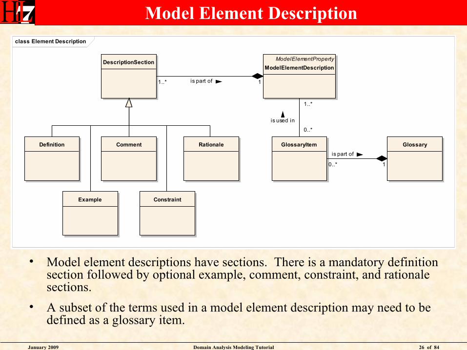
Model Element Description
• Model element descriptions have sections. There is a mandatory definition section followed by optional example, comment, constraint, and rationale sections.
• A subset of the terms used in a model element description may need to be defined as a glossary item.
class Element Description
ModelElementProperty
ModelElementDescription
GlossaryGlossaryItemDefinition
Example
Comment
Constraint
Rationale
DescriptionSection
1..*
is used in
0..*
0..*
is part of
1
1..* is part of 1
January 2009 Domain Analysis Modeling Tutorial 27 of 84
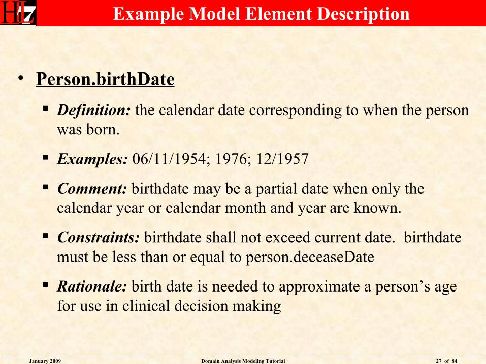
Example Model Element Description
• Person.birthDate
Definition: the calendar date corresponding to when the person was born.
Examples: 06/11/1954; 1976; 12/1957
Comment: birthdate may be a partial date when only the calendar year or calendar month and year are known.
Constraints: birthdate shall not exceed current date. birthdate must be less than or equal to person.deceaseDate
Rationale: birth date is needed to approximate a person’s age for use in clinical decision making
January 2009 Domain Analysis Modeling Tutorial 28 of 84
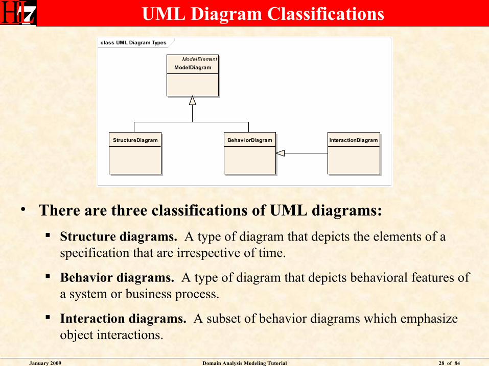
UML Diagram Classifications
• There are three classifications of UML diagrams:
Structure diagrams. A type of diagram that depicts the elements of a specification that are irrespective of time.
Behavior diagrams. A type of diagram that depicts behavioral features of a system or business process.
Interaction diagrams. A subset of behavior diagrams which emphasize object interactions.
class UML Diagram Types
ModelElement
ModelDiagram
Behav iorDiagramStructureDiagram InteractionDiagram
January 2009 Domain Analysis Modeling Tutorial 29 of 84
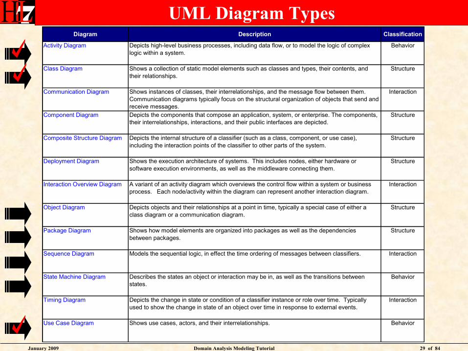
UML Diagram TypesDiagram Description Classification
Activity Diagram Depicts high-level business processes, including data flow, or to model the logic of complex logic within a system.
Behavior
Class Diagram Shows a collection of static model elements such as classes and types, their contents, and their relationships.
Structure
Communication Diagram Shows instances of classes, their interrelationships, and the message flow between them. Communication diagrams typically focus on the structural organization of objects that send and receive messages.
Interaction
Component Diagram Depicts the components that compose an application, system, or enterprise. The components, their interrelationships, interactions, and their public interfaces are depicted.
Structure
Composite Structure Diagram Depicts the internal structure of a classifier (such as a class, component, or use case), including the interaction points of the classifier to other parts of the system.
Structure
Deployment Diagram Shows the execution architecture of systems. This includes nodes, either hardware or software execution environments, as well as the middleware connecting them.
Structure
Interaction Overview Diagram A variant of an activity diagram which overviews the control flow within a system or business process. Each node/activity within the diagram can represent another interaction diagram.
Interaction
Object Diagram Depicts objects and their relationships at a point in time, typically a special case of either a class diagram or a communication diagram.
Structure
Package Diagram Shows how model elements are organized into packages as well as the dependencies between packages.
Structure
Sequence Diagram Models the sequential logic, in effect the time ordering of messages between classifiers. Interaction
State Machine Diagram Describes the states an object or interaction may be in, as well as the transitions between states.
Behavior
Timing Diagram Depicts the change in state or condition of a classifier instance or role over time. Typically used to show the change in state of an object over time in response to external events.
Interaction
Use Case Diagram Shows use cases, actors, and their interrelationships. Behavior
January 2009 Domain Analysis Modeling Tutorial 30 of 84
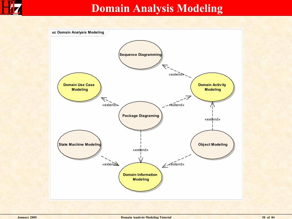
Domain Analysis Modeling
uc Domain Analysis Modeling
Domain Use Case Modeling
Domain Activ ity Modeling
Domain Information Modeling
State Machine Modeling Object Modeling
Package Diagraming
Sequence Diagramming
«extend» «extend»
«extend»
«extend»
«extend» «extend»
«extend»

January 2009 Domain Analysis Modeling Tutorial 31 of 84
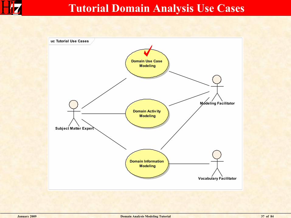
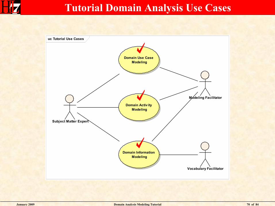
Tutorial Domain Analysis Use Cases
uc Tutorial Use Cases
Domain Activ ity Modeling
Domain Use Case Modeling
Domain Information Modeling
Subject Matter Expert
Modeling Facilitator
Vocabulary Facilitator
January 2009 Domain Analysis Modeling Tutorial 32 of 84
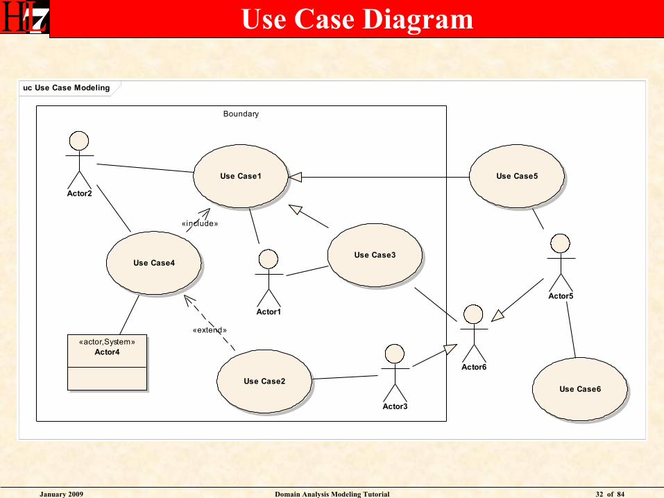
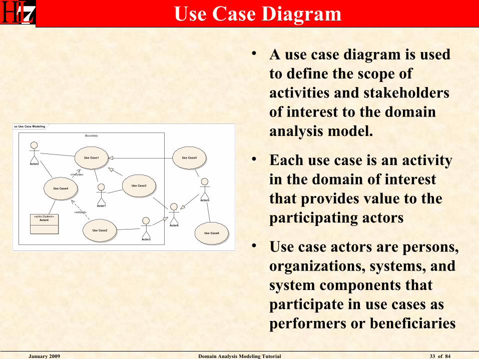
Use Case Diagram
uc Use Case Modeling
Boundary
Use Case1
Use Case2
Use Case3Use Case4
Actor1
Actor2
Actor3
«actor,System»Actor4
Use Case5
Actor5
Actor6
Use Case6
«include»
«extend»
January 2009 Domain Analysis Modeling Tutorial 33 of 84
Use Case Diagram
uc Use Case Modeling
Boundary
Use Case1
Use Case2
Use Case3Use Case4
Actor1
Actor2
Actor3
«actor,System»Actor4
Use Case5
Actor5
Actor6
Use Case6
«include»
«extend»
• A use case diagram is used to define the scope of activities and stakeholders of interest to the domain analysis model.
• Each use case is an activity in the domain of interest that provides value to the participating actors
• Use case actors are persons, organizations, systems, and system components that participate in use cases as performers or beneficiaries
January 2009 Domain Analysis Modeling Tutorial 34 of 84
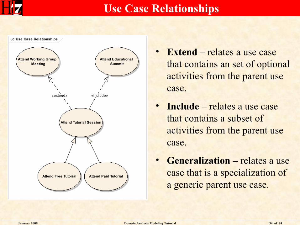
Use Case Relationships
• Extend – relates a use case that contains an set of optional activities from the parent use case.
• Include – relates a use case that contains a subset of activities from the parent use case.
• Generalization – relates a use case that is a specialization of a generic parent use case.
uc Use Case Relationships
Attend Working Group Meeting
Attend Tutorial Session
Attend Educational Summit
Attend Free Tutorial Attend Paid Tutorial
«extend» «include»
January 2009 Domain Analysis Modeling Tutorial 35 of 84
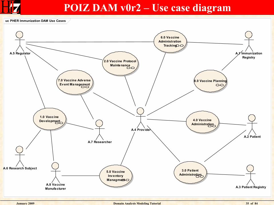
POIZ DAM v0r2 – Use case diagramuc PHER Immunization DAM Use Cases
1.0 Vacc ine Dev elopment
5.0 Vaccine Inv entory
Managment
4.0 Va ccine Administration
2.0 Vaccine Protocol Mainte nance
6.0 Va ccine Administration
Tracking
3.0 Pa tient Administration
7.0 Vaccine Adv erse Ev ent Ma nagement
A.2 Patient
A.4 Prov ider
A.8 Vaccine Manufa cturer
A.1 Immunization Registry
A.7 Researcher
A.5 Regulator
A.6 Research Subject
A.3 Patient Registry
8.0 Vaccine Planning
January 2009 Domain Analysis Modeling Tutorial 36 of 84
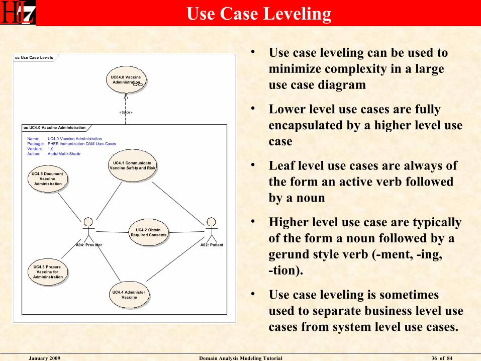
Use Case Leveling
• Use case leveling can be used to minimize complexity in a large use case diagram
• Lower level use cases are fully encapsulated by a higher level use case
• Leaf level use cases are always of the form an active verb followed by a noun
• Higher level use case are typically of the form a noun followed by a gerund style verb (-ment, -ing, -tion).
• Use case leveling is sometimes used to separate business level use cases from system level use cases.
uc Use Case Lev els
UC04.0 Vaccine Administration
uc UC4.0 Vaccine Administration
UC4.1 Communicate Vaccine Safety and Risk
UC4.3 Prepare Vaccine for
Admininstration
UC4.4 Administer Vaccine
UC4.5 Document Vaccine
Administration
A04: Prov ider A02: Patient
UC4.2 Obtain Required Consents
Name:Package:Version:Author:
UC4.0 Vaccine AdministrationPHER Immunization DAM Uses Cases1.0AbdulMalik Shakir
«trace»
January 2009 Domain Analysis Modeling Tutorial 37 of 84
Tutorial Domain Analysis Use Cases
uc Tutorial Use Cases
Domain Activ ity Modeling
Domain Use Case Modeling
Domain Information Modeling
Subject Matter Expert
Modeling Facilitator
Vocabulary Facilitator
January 2009 Domain Analysis Modeling Tutorial 38 of 84
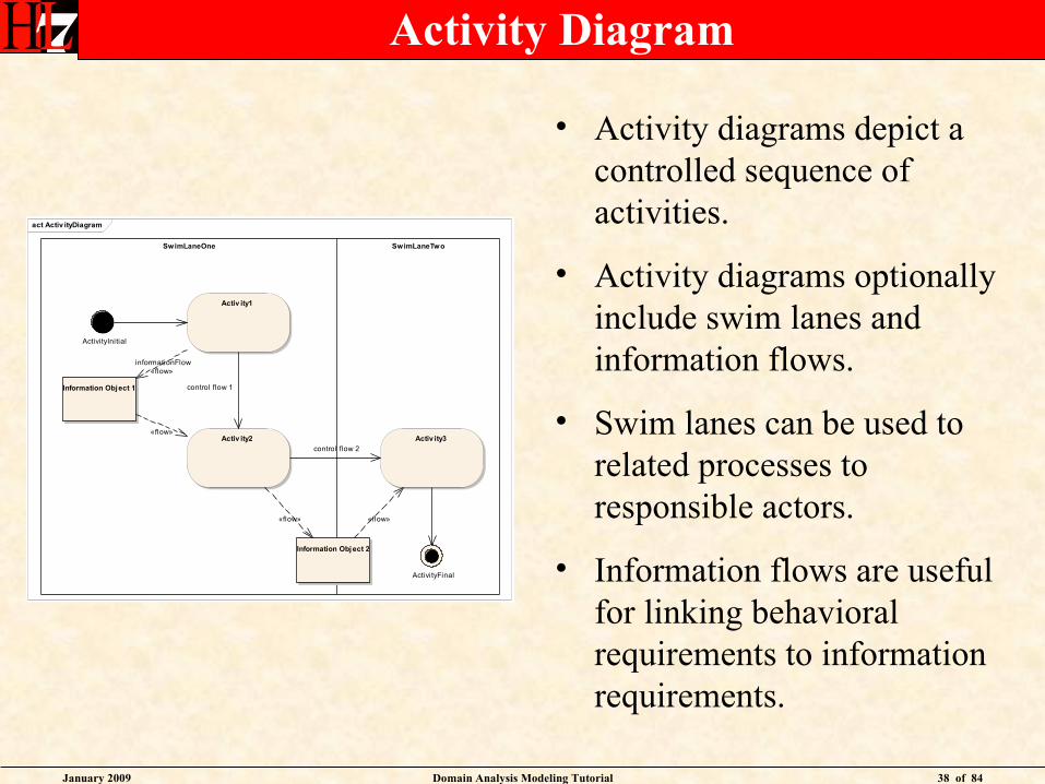
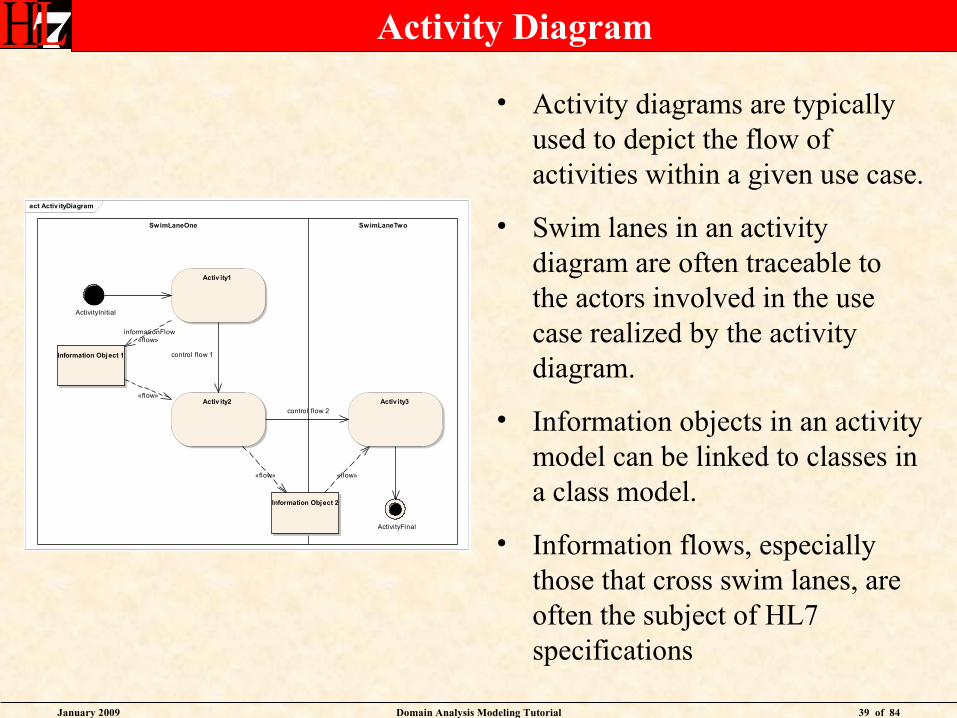
Activity Diagram
• Activity diagrams depict a controlled sequence of activities.
• Activity diagrams optionally include swim lanes and information flows.
• Swim lanes can be used to related processes to responsible actors.
• Information flows are useful for linking behavioral requirements to information requirements.
act Activ ityDiagram
SwimLaneOne SwimLaneTwo
Activ ity1
Activ ity2 Activ ity3
Information Obj ect 2
Information Object 1
ActivityInitial
ActivityFinal
control flow 1
control flow 2
informationFlow«flow»
«flow»
«flow» «flow»
January 2009 Domain Analysis Modeling Tutorial 39 of 84
Activity Diagram
act Activ ityDiagram
SwimLaneOne SwimLaneTwo
Activ ity1
Activ ity2 Activ ity3
Information Obj ect 2
Information Object 1
ActivityInitial
ActivityFinal
control flow 1
control flow 2
informationFlow«flow»
«flow»
«flow» «flow»
• Activity diagrams are typically used to depict the flow of activities within a given use case.
• Swim lanes in an activity diagram are often traceable to the actors involved in the use case realized by the activity diagram.
• Information objects in an activity model can be linked to classes in a class model.
• Information flows, especially those that cross swim lanes, are often the subject of HL7 specifications
January 2009 Domain Analysis Modeling Tutorial 40 of 84
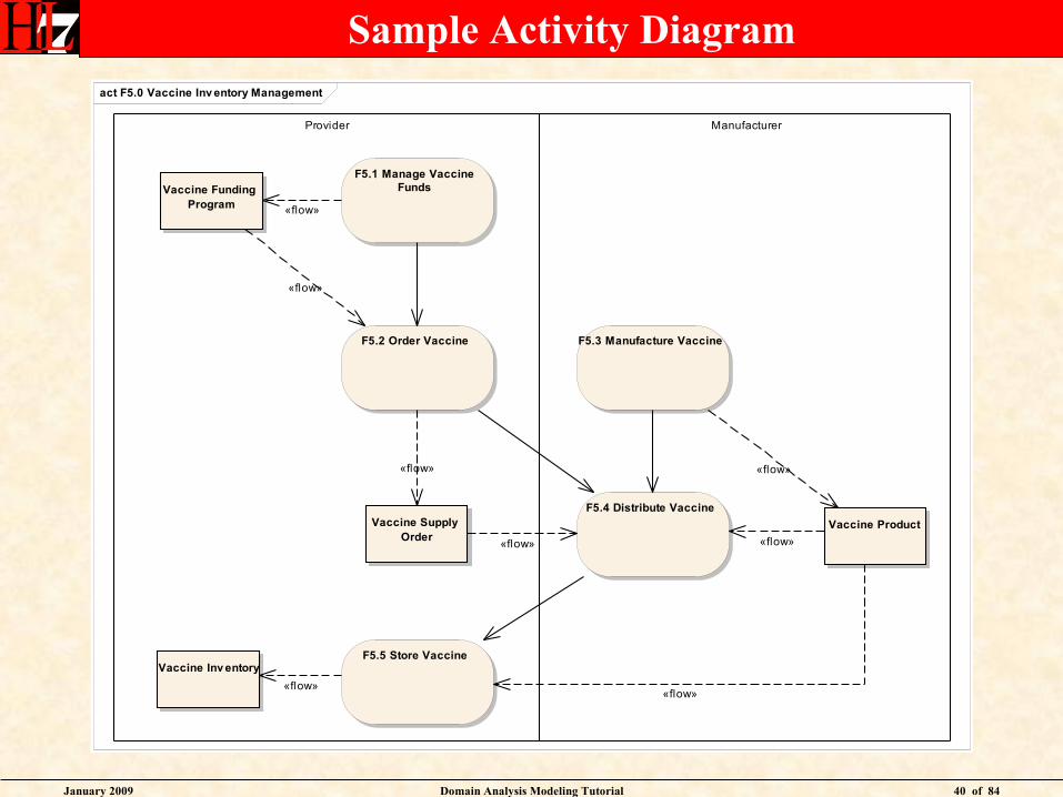
Sample Activity Diagramact F5.0 Vaccine Inv entory Management
Provider Manufacturer
F5.1 Manage VaccineFunds
F5.3 Manufacture VaccineF5.2 Order Vaccine
F5.4 Distribute Vaccine
F5.5 Store Vaccine
Vaccine Funding Program
Vaccine Supply Order
Vaccine Product
Vaccine Inv entory
«flow»
«flow»«flow»
«flow»
«flow»
«flow» «flow»
«flow»
January 2009 Domain Analysis Modeling Tutorial 41 of 84
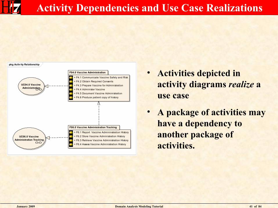
Activity Dependencies and Use Case Realizations
• Activities depicted in activity diagrams realize a use case
• A package of activities may have a dependency to another package of activities.
pkg Activ ity Relationship
F04.0 Vaccine Administration
+ F4.1 Communicate Vaccine Safety and Risk
+ F4.2 Obtain Required Consents
+ F4.3 Prepare Vaccine for Administration
+ F4.4 Administer Vaccine
+ F4.5 Document Vaccine Administration
+ F4.6 Produce patient copy of history
F06.0 Vaccine Administration Tracking
+ F6.1 Report Vaccine Admininstration History
+ F6.2 Store Vaccine Administration History
+ F6.3 Retrieve Vaccine Administration History
+ F6.4 Assess Vaccine Administration History
UC04.0 Vaccine Administration
UC06.0 Vaccine Administration Tracking
January 2009 Domain Analysis Modeling Tutorial 42 of 84
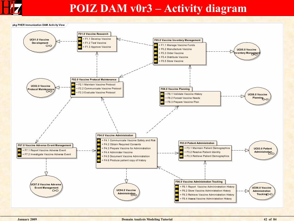
POIZ DAM v0r3 – Activity diagrampkg PHER Immunization DAM Activ ity View
UC01.0 Vaccine Development
UC02.0 Vaccine Protocol Maintenance
UC03.0 Patient Administration
UC04.0 Vaccine Administration
UC05.0 Vaccine Inventory Managment
UC06.0 Vaccine Administration
Tracking
UC07.0 Vaccine Adverse Ev ent Management
F01.0 Vaccine Research
+ F1.1 Develop Vaccine
+ F1.2 Test Vaccine
+ F1.3 Approve Vaccine
F02.0 Vaccine Protocol Maintenance
+ F2.1 Maintain Vaccine Protocol
+ F2.2 Communicate Vaccine Protocol
+ F2.3 Evaluate Vaccine Protocol
F04.0 Vaccine Administration
+ F4.1 Communicate Vaccine Safety and Risk
+ F4.2 Obtain Required Consents
+ F4.3 Prepare Vaccine for Administration
+ F4.4 Administer Vaccine
+ F4.5 Document Vaccine Administration
+ F4.6 Produce patient copy of history
F06.0 Vaccine Administration Tracking
+ F6.1 Report Vaccine Admininstration History
+ F6.2 Store Vaccine Administration History
+ F6.3 Retrieve Vaccine Administration History
+ F6.4 Assess Vaccine Administration History
F07.0 Vaccine Adverse Ev ent Management
+ F7.1 Report Vaccine Adverse Event
+ F7.2 Investigate Vaccine Adverse Event
F05.0 Vaccine Inv entory Management
+ F1.1 Manage Vaccine Funds
+ F5.2 Manufacture Vaccine
+ F5.3 Order Vaccine
+ F5.4 Distribute Vaccine
+ F5.5 Store Vaccine
F03.0 Patient Administration
+ F3.1 Maintain Patient Demographics
+ F3.2 Resolve Patient Identity
+ F3.3 Retrieve Patient Demographics
F08.0 Vaccine Planning
+ F8.1 Validate Vaccine History
+ F8.2 Forcast Vaccine Needs
+ F8.3 Prepare Vaccine Plan
UC08.0 Vaccine Planning

January 2009 Domain Analysis Modeling Tutorial 43 of 84
Tutorial Domain Analysis Use Cases
uc Tutorial Use Cases
Domain Activ ity Modeling
Domain Use Case Modeling
Domain Information Modeling
Subject Matter Expert
Modeling Facilitator
Vocabulary Facilitator
January 2009 Domain Analysis Modeling Tutorial 44 of 84
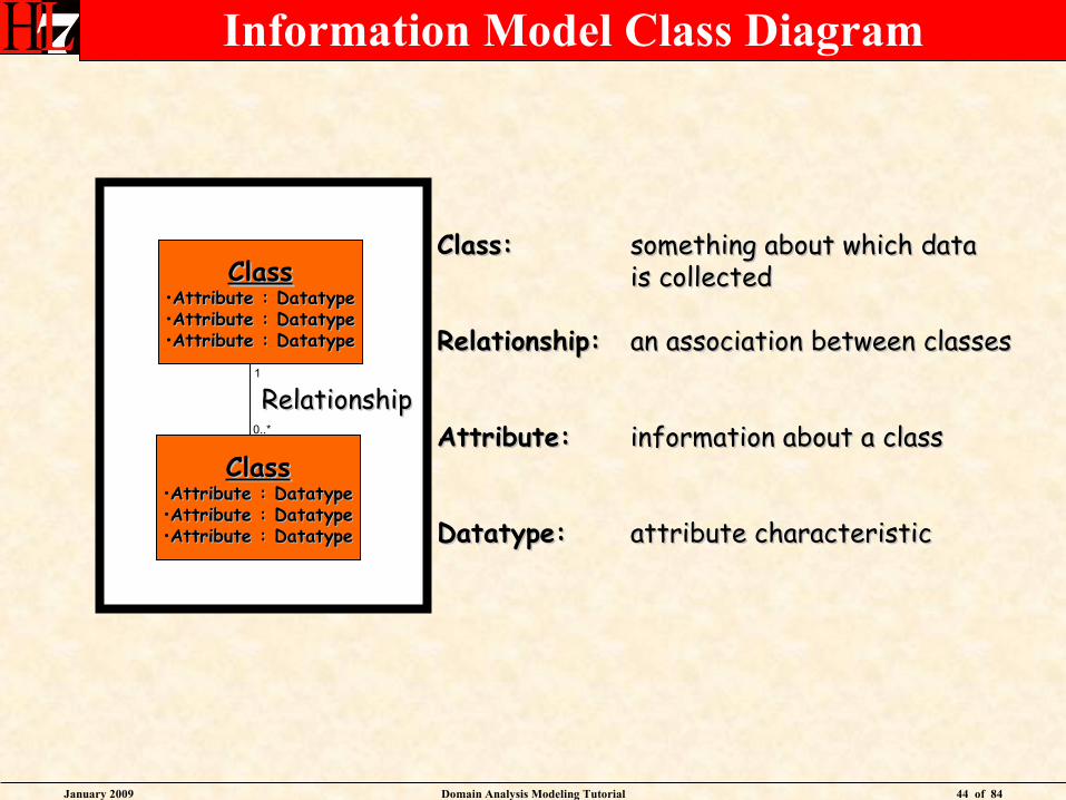
Information Model Class Diagram
ClassClass•Attribute : DatatypeAttribute : Datatype•Attribute : DatatypeAttribute : Datatype•Attribute : DatatypeAttribute : Datatype
ClassClass•Attribute : DatatypeAttribute : Datatype•Attribute : DatatypeAttribute : Datatype•Attribute : DatatypeAttribute : Datatype
RelationshipRelationship
Class:Class: something about which datasomething about which datais collectedis collected
Relationship:Relationship: an association between classesan association between classes
Attribute:Attribute: information about a classinformation about a class
Datatype:Datatype: attribute characteristicattribute characteristic
0..*
1
January 2009 Domain Analysis Modeling Tutorial 45 of 84
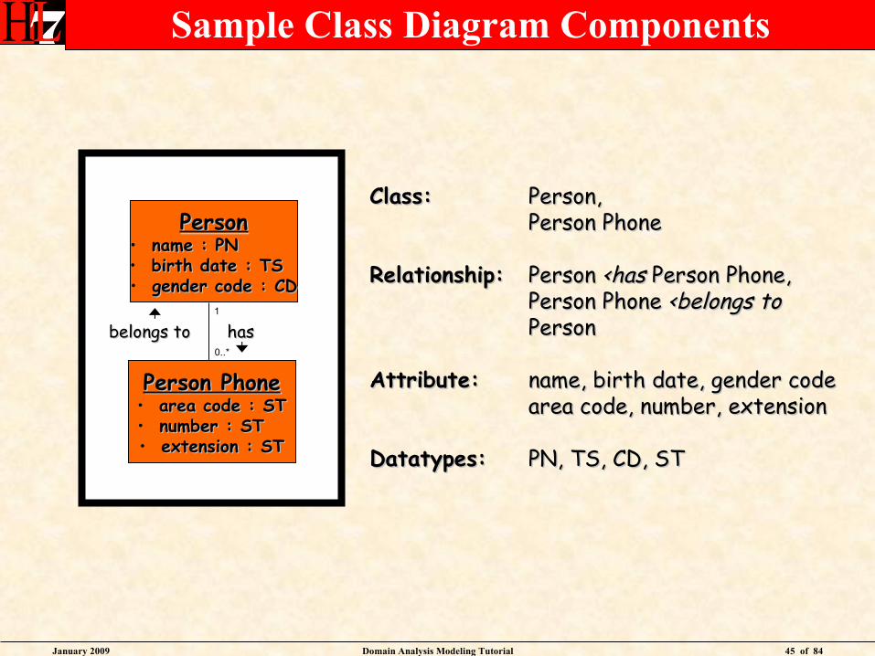
Sample Class Diagram Components
PersonPerson• name : PN name : PN • birth date : TS birth date : TS • gender code : CDgender code : CD
Person PhonePerson Phone• area code : STarea code : ST• number : ST number : ST • extension : STextension : ST
hashas
Class:Class: Person,Person,Person PhonePerson Phone
Relationship:Relationship: Person Person <has<has Person Phone, Person Phone,Person Phone Person Phone <belongs to<belongs toPersonPerson
Attribute:Attribute: name, birth date, gender codename, birth date, gender codearea code, number, extensionarea code, number, extension
Datatypes:Datatypes: PN, TS, CD, STPN, TS, CD, ST
belongs tobelongs to0..*
1

January 2009 Domain Analysis Modeling Tutorial 46 of 84
Domain Information Modeling
• Identify major classes
• Determine relationships among classes
• Add class attributes
• Assign attribute datatypes
• Enumerate coded attribute values
January 2009 Domain Analysis Modeling Tutorial 47 of 84
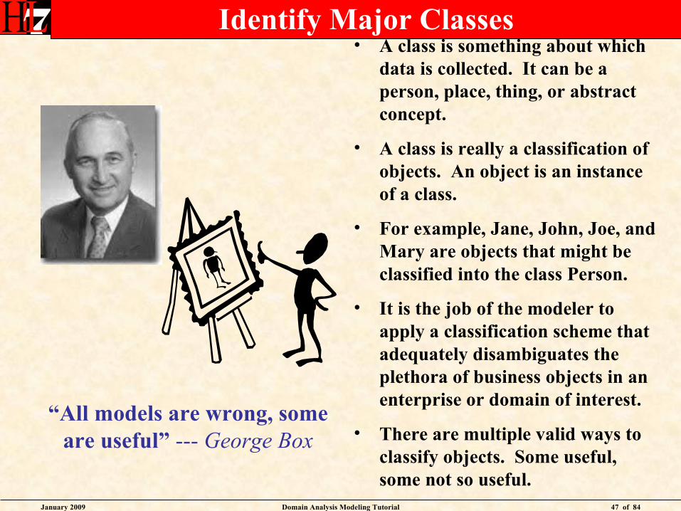
Identify Major Classes• A class is something about which
data is collected. It can be a person, place, thing, or abstract concept.
• A class is really a classification of objects. An object is an instance of a class.
• For example, Jane, John, Joe, and Mary are objects that might be classified into the class Person.
• It is the job of the modeler to apply a classification scheme that adequately disambiguates the plethora of business objects in an enterprise or domain of interest.
• There are multiple valid ways to classify objects. Some useful, some not so useful.
“All models are wrong, some are useful” --- George Box

January 2009 Domain Analysis Modeling Tutorial 48 of 84
Sample Healthcare Finance Domain Classesclass SampleClasses
Encounter
Patient
Physician
Clinic
Payor
Hospital
Payment
Serv ice
Charge
Procedure
Claim
January 2009 Domain Analysis Modeling Tutorial 49 of 84
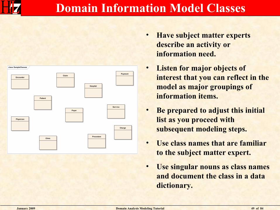
Domain Information Model Classes
• Have subject matter experts describe an activity or information need.
• Listen for major objects of interest that you can reflect in the model as major groupings of information items.
• Be prepared to adjust this initial list as you proceed with subsequent modeling steps.
• Use class names that are familiar to the subject matter expert.
• Use singular nouns as class names and document the class in a data dictionary.
class SampleClasses
Encounter
Patient
Physician
Clinic
Payor
Hospital
Payment
Serv ice
Charge
Procedure
Claim

January 2009 Domain Analysis Modeling Tutorial 50 of 84
Domain Information Modeling
Identify major classes
• Determine relationships among classes
• Add class attributes
• Assign attribute datatypes
• Enumerate coded attribute values
January 2009 Domain Analysis Modeling Tutorial 51 of 84
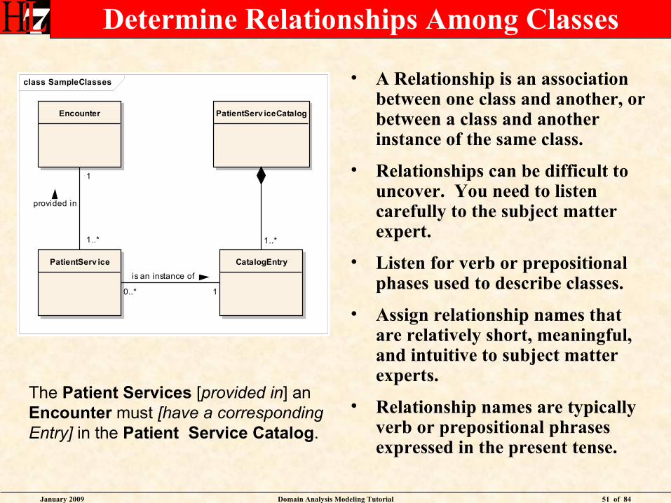
Determine Relationships Among Classes
• A Relationship is an association between one class and another, or between a class and another instance of the same class.
• Relationships can be difficult to uncover. You need to listen carefully to the subject matter expert.
• Listen for verb or prepositional phases used to describe classes.
• Assign relationship names that are relatively short, meaningful, and intuitive to subject matter experts.
• Relationship names are typically verb or prepositional phrases expressed in the present tense.
class SampleClasses
Encounter
PatientServ ice
PatientServ iceCatalog
CatalogEntry
1..*
0..*
is an instance of
1
1
provided in
1..*
The Patient Services [provided in] anEncounter must [have a correspondingEntry] in the Patient Service Catalog.
January 2009 Domain Analysis Modeling Tutorial 52 of 84
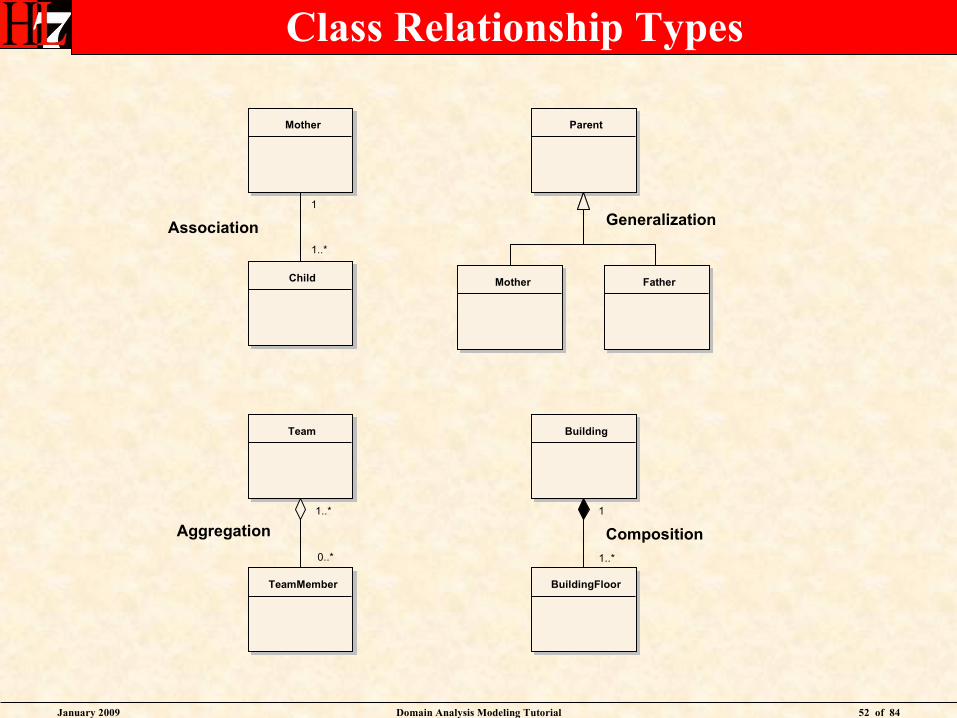
Class Relationship Types
Mother
Child
Parent
Mother
Building
BuildingFloor
Team
TeamMember
Father
1
1..*
1..*
1
0..*
1..*
Association Generalization
Aggregation Composition
January 2009 Domain Analysis Modeling Tutorial 53 of 84
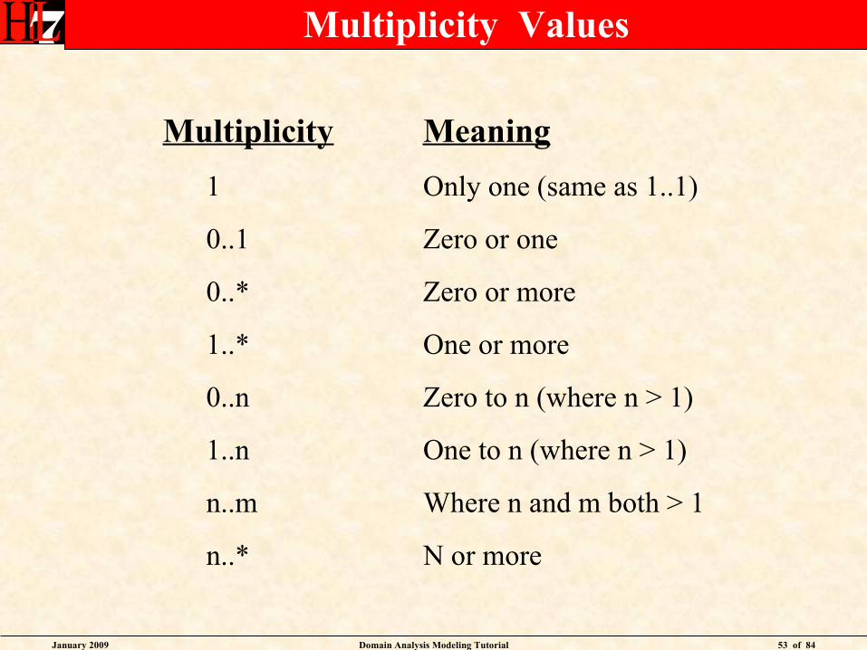
Multiplicity Values
Multiplicity Meaning
1 Only one (same as 1..1)
0..1 Zero or one
0..* Zero or more
1..* One or more
0..n Zero to n (where n > 1)
1..n One to n (where n > 1)
n..m Where n and m both > 1
n..* N or more
January 2009 Domain Analysis Modeling Tutorial 54 of 84
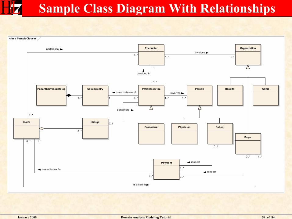
Sample Class Diagram With Relationships
class SampleClasses
Encounter
PatientPhysician
Clinic
Payor
Hospital
Payment
PatientServ ice
Charge
Procedure
Claim
PatientServ iceCatalog CatalogEntry Person
Organization
1..* 0..*
is an instance of
1
1
provided in
1..*
0..1
pertains to
1
0..*
0..*
pertains to
0..*
1..*
involves
1..*
0..*
involves
1..*
0..1
renders
0..*
0..*
renders
0..*0..*
is remittance for
1..*
1..*
is bil led to
0..*
January 2009 Domain Analysis Modeling Tutorial 55 of 84
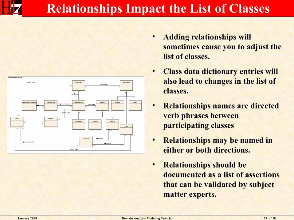
Relationships Impact the List of Classes
• Adding relationships will sometimes cause you to adjust the list of classes.
• Class data dictionary entries will also lead to changes in the list of classes.
• Relationships names are directed verb phrases between participating classes
• Relationships may be named in either or both directions.
• Relationships should be documented as a list of assertions that can be validated by subject matter experts.
class SampleClasses
Encounter
PatientPhysician
Clinic
Payor
Hospital
Payment
PatientServ ice
Charge
Procedure
Claim
PatientServ iceCatalog CatalogEntry Person
Organization
1..* 0..*
is an instance of
1
1
provided in
1..*
0..1
pertains to
1
0..*
0..*
pertains to
0..*
1..*
involves
1..*
0..*
involves
1..*
0..1
renders
0..*
0..*
renders
0..*0..*
is remittance for
1..*
1..*
is bil led to
0..*
January 2009 Domain Analysis Modeling Tutorial 56 of 84
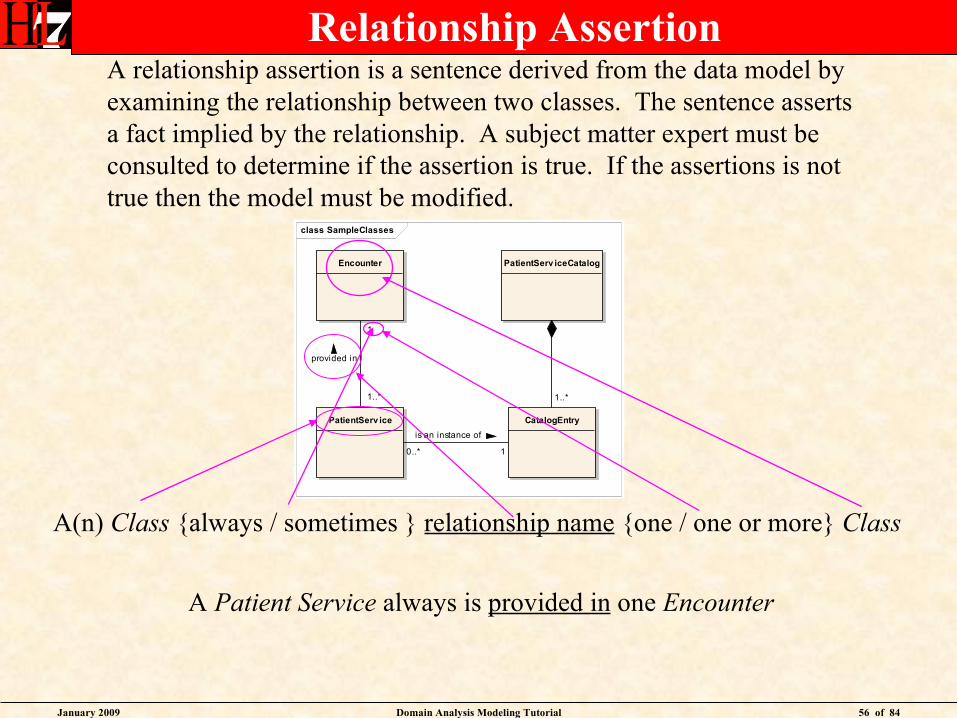
class SampleClasses
Encounter
PatientServ ice
PatientServ iceCatalog
CatalogEntry
1..*
0..*
is an instance of
1
1
provided in
1..*
Relationship Assertion
A(n) Class {always / sometimes } relationship name {one / one or more} Class
A relationship assertion is a sentence derived from the data model byexamining the relationship between two classes. The sentence assertsa fact implied by the relationship. A subject matter expert must beconsulted to determine if the assertion is true. If the assertions is not true then the model must be modified.
A Patient Service always is provided in one Encounter
January 2009 Domain Analysis Modeling Tutorial 57 of 84
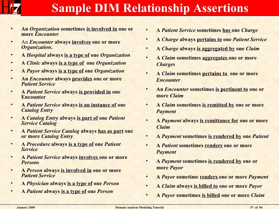
Sample DIM Relationship Assertions
• An Organization sometimes is involved in one or more Encounter
• An Encounter always involves one or more Organization.
• A Hospital always is a type of one Organization
• A Clinic always is a type of one Organization
• A Payor always is a type of one Organization
• An Encounter always provides one or more Patient Service
• A Patient Service always is provided in one Encounter
• A Patient Service always is an instance of one Catalog Entry
• A Catalog Entry always is part of one Patient Service Catalog
• A Patient Service Catalog always has as part one or more Catalog Entry
• A Procedure always is a type of one Patient Service
• A Patient Service always involves one or more Persons
• A Person always is involved in one or more Patient Service
• A Physician always is a type of one Person
• A Patient always is a type of one Person
• A Patient Service sometimes has one Charge
• A Charge always pertains to one Patient Service
• A Charge always is aggregated by one Claim
• A Claim sometimes aggregates one or more Charges
• A Claim sometimes pertains to one or more Encounter
• An Encounter sometimes is pertinent to one or more Claim
• A Claim sometimes is remitted by one or more Payment
• A Payment always is remittance for one or more Claim
• A Payment sometimes is rendered by one Patient
• A Patient sometimes renders one or more Payment
• A Payment sometimes is rendered by one or more Payor
• A Payor sometime renders one or more Payment
• A Claim always is billed to one or more Payor
• A Payor sometimes is billed one or more Claim

January 2009 Domain Analysis Modeling Tutorial 58 of 84
Review DIM Relationship Assertions
• Expect a wide range of reactions from the SMEs as they consider the relationship assertions.
• Resist the temptation to remodel as the assertions are being reviewed.
• Capture significant business rules as comments on the relationships.
• Pay particular attention to the subtype / super type structures.
• Replace many-to-many relationships with associative classes.
• When the review is complete, record the findings and then update the data model.
• Reissue the relationship assertions for review
• Repeat until done.
Relationship
Assertions
January 2009 Domain Analysis Modeling Tutorial 59 of 84
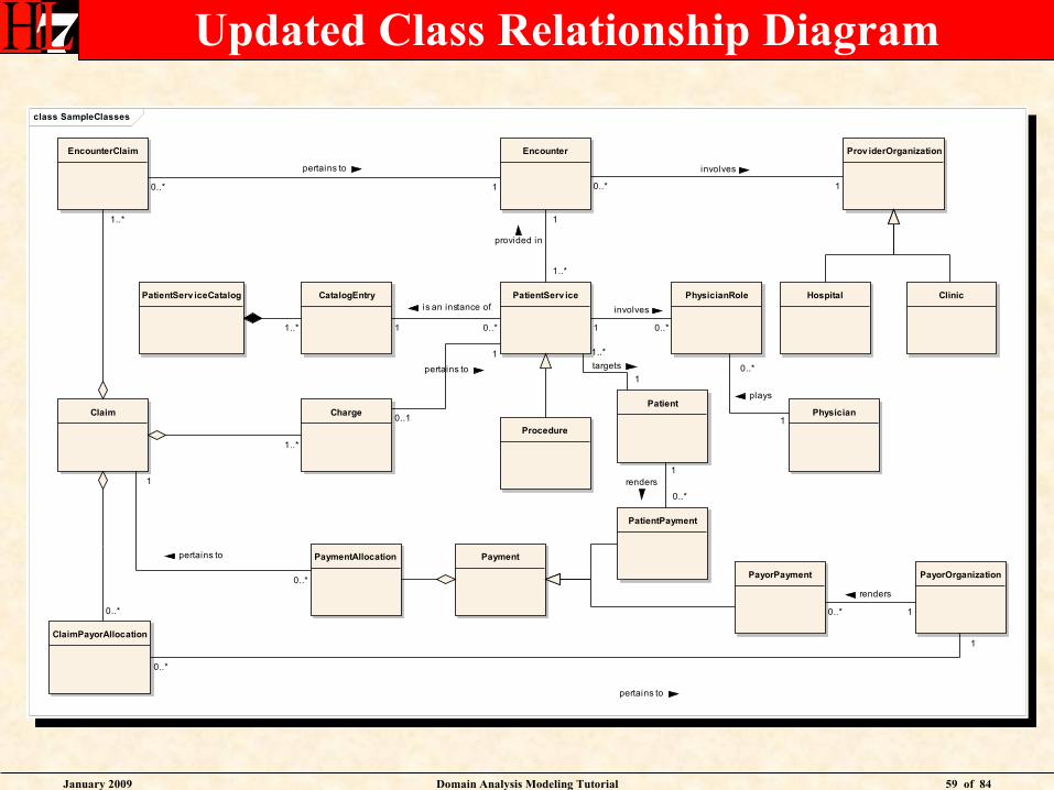
Updated Class Relationship Diagram
class SampleClasses
Encounter
PatientPhysician
Clinic
PayorOrganization
Hospital
Payment
PatientServ ice
Charge
Procedure
Claim
PatientServ iceCatalog CatalogEntry PhysicianRole
Prov iderOrganizationEncounterClaim
PaymentAllocation
ClaimPayorAllocation
PatientPayment
PayorPayment
1..* 0..*
is an instance of
1
1
provided in
1..*
0..1
pertains to
1
1..*
1
involves
0..*
0..*
involves
1
1..*
0..*
pertains to
1
0..*
pertains to
1
0..*
0..*
pertains to
1
1renders
0..*
1
renders
0..*
1
plays
0..*
1..*
targets
1

January 2009 Domain Analysis Modeling Tutorial 60 of 84
Domain Information Modeling
Identify major classes
Determine relationships among classes
• Add class attributes
• Assign attribute datatypes
• Enumerate coded attribute values
January 2009 Domain Analysis Modeling Tutorial 61 of 84
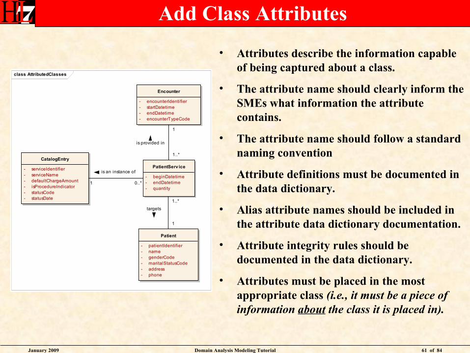
Add Class Attributes
• Attributes describe the information capable of being captured about a class.
• The attribute name should clearly inform the SMEs what information the attribute contains.
• The attribute name should follow a standard naming convention
• Attribute definitions must be documented in the data dictionary.
• Alias attribute names should be included in the attribute data dictionary documentation.
• Attribute integrity rules should be documented in the data dictionary.
• Attributes must be placed in the most appropriate class (i.e., it must be a piece of information about the class it is placed in).
class AttributedClasses
Encounter
- encounterIdentifier- startDatetime- endDatetime- encounterTypeCode
Patient
- patientIdentifier- name- genderCode- maritalStatusCode- address- phone
PatientServ ice
- beginDatetime- endDatetime- quantity
CatalogEntry
- serviceIdentifier- serviceName- defaultChargeAmount- isProcedureIndicator- statusCode- statusDate
1..*
targets
1
1
is provided in
1..*
0..*
is an instance of
1
January 2009 Domain Analysis Modeling Tutorial 62 of 84
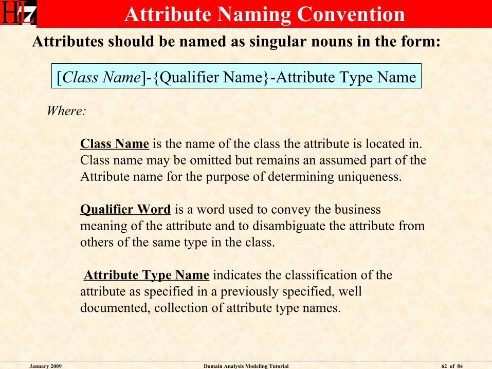
Attribute Naming Convention
[Class Name]-{Qualifier Name}-Attribute Type Name
Attributes should be named as singular nouns in the form:
Where:
Class Name is the name of the class the attribute is located in.Class name may be omitted but remains an assumed part of theAttribute name for the purpose of determining uniqueness.
Qualifier Word is a word used to convey the business meaning of the attribute and to disambiguate the attribute from others of the same type in the class.
Attribute Type Name indicates the classification of the attribute as specified in a previously specified, well documented, collection of attribute type names.
January 2009 Domain Analysis Modeling Tutorial 63 of 84
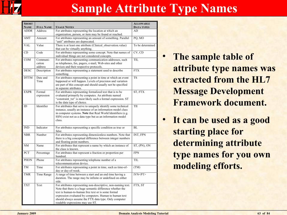
Sample Attribute Type NamesSHORT
NAME FULL NAME USAGE NOTES
ALLOWABLE
DATA TYPES
ADDR Address For attributes representing the location at which anorganization, person, or item may be found or reached.
AD
AMT Amount For attributes representing an amount of something. Parallel“unit” attributes are deprecated.
PQ, MO
VAL Value There is at least one attribute (Clinical_observation.value)that can be virtually anything.
To be determined
CD Code For attributes representing some concept. Note that names ofindividual things are not considered concepts.
CV, CD
COM Communi-cationaddress
For attributes representing communication addresses, suchas telephones, fax, pagers, e-mail, Web-sites and otherdevices and their respective protocols.
TIL
DESC Description For attributes representing a statement used to describesomething.
FTX
DTTM Date andTime
For attributes representing a point in time at which an eventhappened or will happen. Levels of precision and variationare part of this concept and should usually not be specifiedin separate attributes.
TS
EXPR Formalexpression
For attributes representing formalized text that is to beevaluated primarily by computes. An attribute named“constraint_txt” is most likely such a formal expression. STis the data type of choice.
ST, FTX
ID Identifier For attributes that serve to uniquely identify some technicalinstance, usually an instance of an information model classin computer systems. Note that Real World Identifiers (e.g.SSN) exist not as a data type but as an information modelclass.
TII
IND Indicator For attributes representing a specific condition as true orfalse.
BL
NBR Number For attributes representing dimensionless numbers. Note thatthere is a big conceptual difference between integer numbersand floating point numbers.
INT, FPN
NM Name For attributes that represent a name by which an instance ofthe class is known.
ST, (PN), ON
PCT Percentage For attributes that represent a fraction or proportion perhundred.
FPN
PHON Phone For attributes representing telephone number of atelecommunication device.
TIL
TM Time For attributes representing a point in time, such as time-of-day or day-of-week.
(TM)
TMR Time Range A range of time between a start and an end time having aduration. The range may be infinite or undefined on eitherside.
IVN<PT>
TXT Text For attributes representing non-descriptive, non-naming text.Note that there is a huge semantic difference whether thetext is human-to-human free text or is some formalexpression evaluated by computers. Human to human textshould always assume the FTX data type. Only computerreadable expressions may use ST.
FTX, ST
• The sample table of attribute type names was extracted from the HL7 Message Development Framework document.
• It can be used as a good starting place for determining attribute type names for you own modeling efforts.

January 2009 Domain Analysis Modeling Tutorial 64 of 84
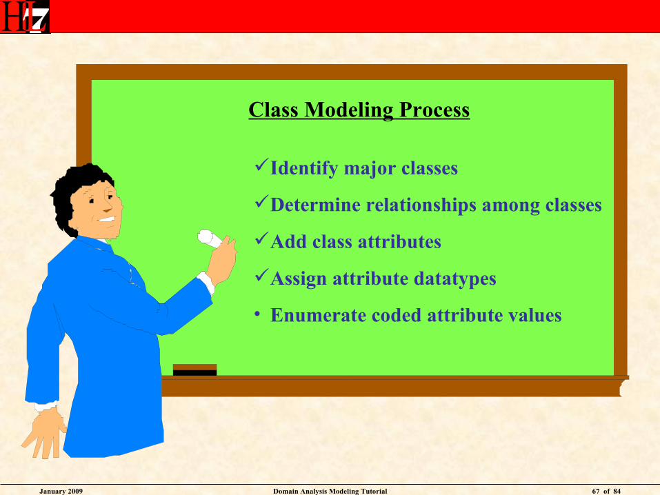
Class Modeling Process
Identify major classes
Determine relationships among classes
Add class attributes
• Assign attribute datatypes
• Enumerate coded attribute values
January 2009 Domain Analysis Modeling Tutorial 65 of 84
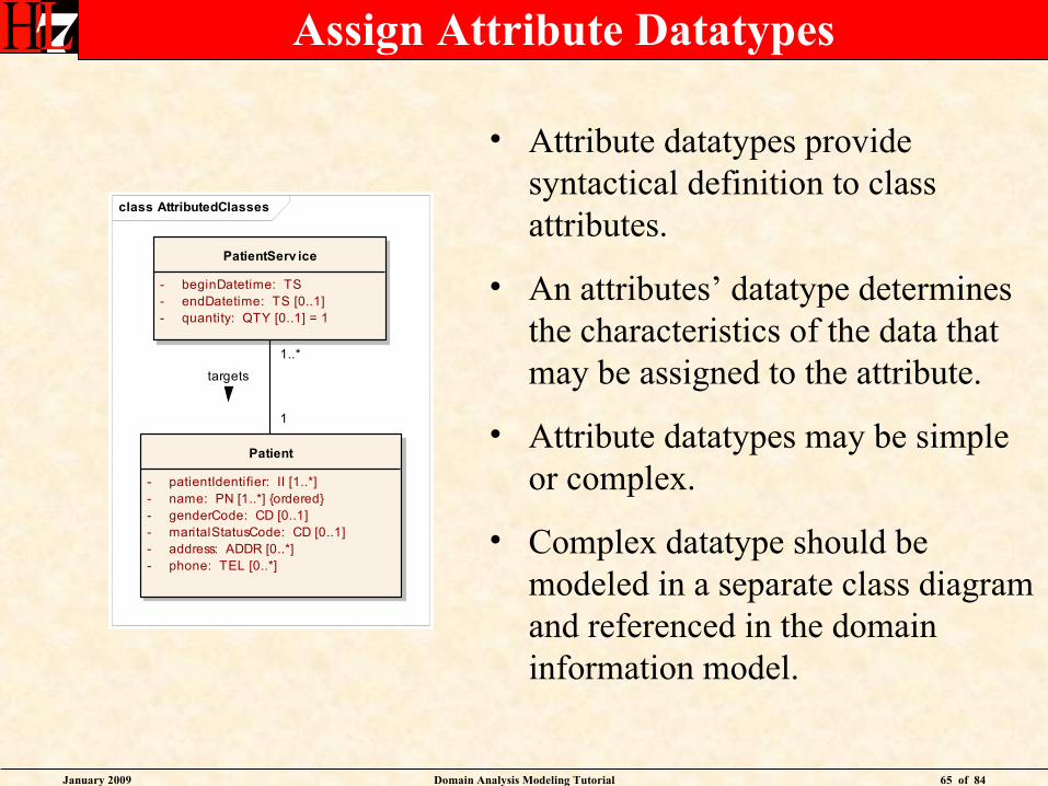
Assign Attribute Datatypes
• Attribute datatypes provide syntactical definition to class attributes.
• An attributes’ datatype determines the characteristics of the data that may be assigned to the attribute.
• Attribute datatypes may be simple or complex.
• Complex datatype should be modeled in a separate class diagram and referenced in the domain information model.
class AttributedClasses
Patient
- patientIdentifier: II [1..*]- name: PN [1..*] {ordered}- genderCode: CD [0..1]- maritalStatusCode: CD [0..1]- address: ADDR [0..*]- phone: TEL [0..*]
PatientServ ice
- beginDatetime: TS- endDatetime: TS [0..1]- quantity: QTY [0..1] = 1
1..*
targets
1
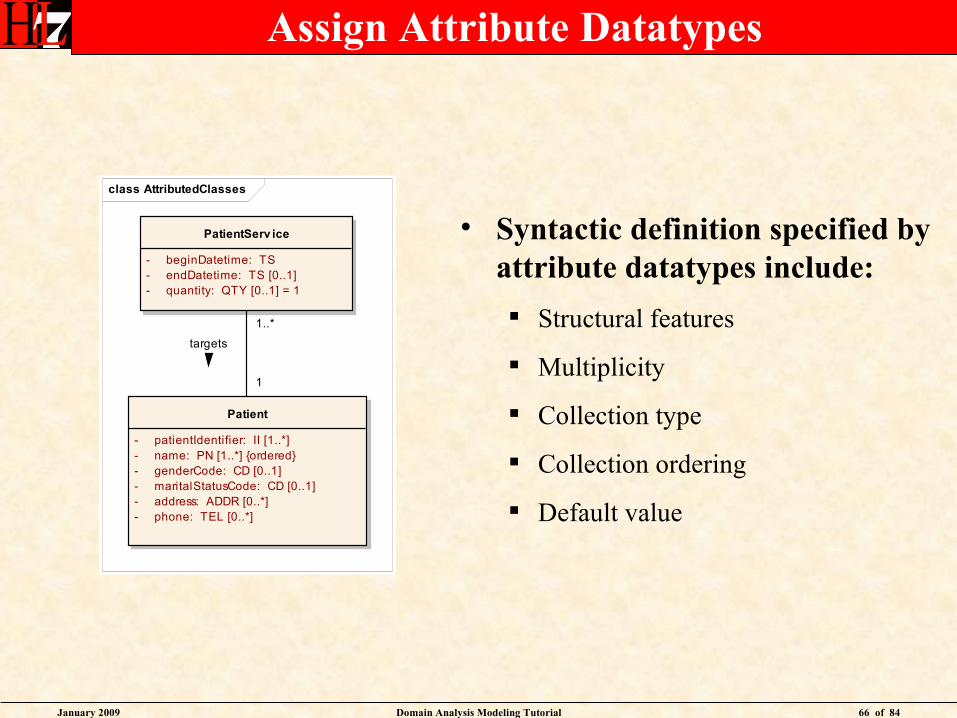
January 2009 Domain Analysis Modeling Tutorial 66 of 84
Assign Attribute Datatypes
• Syntactic definition specified by attribute datatypes include:
Structural features
Multiplicity
Collection type
Collection ordering
Default value
class AttributedClasses
Patient
- patientIdentifier: II [1..*]- name: PN [1..*] {ordered}- genderCode: CD [0..1]- maritalStatusCode: CD [0..1]- address: ADDR [0..*]- phone: TEL [0..*]
PatientServ ice
- beginDatetime: TS- endDatetime: TS [0..1]- quantity: QTY [0..1] = 1
1..*
targets
1
January 2009 Domain Analysis Modeling Tutorial 67 of 84
Class Modeling Process
Identify major classes
Determine relationships among classes
Add class attributes
Assign attribute datatypes
• Enumerate coded attribute values
January 2009 Domain Analysis Modeling Tutorial 68 of 84
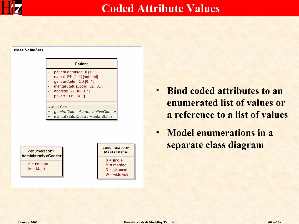
Coded Attribute Values
• Bind coded attributes to an enumerated list of values or a reference to a list of values
• Model enumerations in a separate class diagram
class ValueSets
«enumeration»Administrativ eGender
F = Female M = Male
«enumeration»MaritalStatus
S = single M = married D = divorced W = widowed
Patient
- patientIdentifier: II [1..*]- name: PN [1..*] {ordered}- genderCode: CD [0..1]- maritalStatusCode: CD [0..1]- address: ADDR [0..*]- phone: TEL [0..*]
«valueSet»+ genderCode : AdministrativeGender+ maritalStatusCode : MaritalStatus

January 2009 Domain Analysis Modeling Tutorial 69 of 84
Class Modeling Process
Identify major classes
Determine relationships among classes
Add class attributes
Assign attribute datatypes
Enumerate coded attribute values
January 2009 Domain Analysis Modeling Tutorial 70 of 84
Tutorial Domain Analysis Use Cases
uc Tutorial Use Cases
Domain Activ ity Modeling
Domain Use Case Modeling
Domain Information Modeling
Subject Matter Expert
Modeling Facilitator
Vocabulary Facilitator
January 2009 Domain Analysis Modeling Tutorial 71 of 84
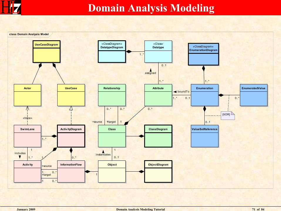
Domain Analysis Modeling
class Domain Analysis Model
UseCaseDiagram
UseCaseActor
Activ ityDiagram
Activ ity
SwimLane
ObjectInformationFlow ObjectDiagram
Class
Attribute
ClassDiagram
«Class»Datatype
Enumeration EnumeratedValue
ValueSetReference
{XOR}
«ClassDiagram»DatatypeDiagram «ClassDiagram»
EnumerationDiagram
Relationship
«trace»
1..*
1..*
includes1
0..*1..*
+source
1 0..*+target
1 0..*
1
1
instantiates0..1
0..*
0..1
boundTo
1..* 0..*
0..1
1..*
1..*
assigned
0..1
1..*
0..*
+source 1
0..*
+target 1

January 2009 Domain Analysis Modeling Tutorial 72 of 84
Domain Analysis Controversies
• UML Notation
• Tooling
• RIM traceability
• Balloting
• Scope Project / Committee
January 2009 Domain Analysis Modeling Tutorial 73 of 84
UML Notation
• The HDF highly recommends the use of UML as the modeling notation for Domain Analysis Models
• Other notations to consider include IDEF, IE, and Visio block diagrams
• Diagrams are often supplemented with spreadsheets, reference documents, storyboards, and other illuminating materials
• The primary goal is to use diagrams and other techniques that resonate with subject matter experts and allows them to validate the model
January 2009 Domain Analysis Modeling Tutorial 74 of 84
Tooling
• HL7 does not specify a particular tool be used for domain analysis modeling
• IBM has agreed to allow HL7 to use Rational tools for specification design at no cost
• An UML profile specific to HL7 modeling requirements has been created for Rational tools
• Enterprise Architect (Sparx systems) is a very popular domain analysis tool
• Other tools include Visio, Magic Draw, and a host of others (http://en.wikipedia.org/wiki/List_of_UML_tools)
• The most important tooling features are support of UML 2.0 and UML 2.0 XMI.
January 2009 Domain Analysis Modeling Tutorial 75 of 84
RIM Traceability
• The final step of requirements documentation is to harmonize the DAM with HL7 reference models
• Some find that adopting RIM class patterns in their domain information model simplifies this harmonization
• Others find that adopting RIM class patterns in their domain information model alienates their subject matter experts
• The jury is out as far as which approach is best. The important thing is to produce a model that is verifiable by subject matter experts
• RIM traceability is most commonly achieved by creating a DMIM with mappings to the DIM in the domain analysis model.
January 2009 Domain Analysis Modeling Tutorial 76 of 84
Balloting
• Workgroups have taken different positions with regard to balloting their DAMs.
• Some consider the DAM an internal work item only. Portions of the DAM may be included as background documentation for specifications undergoing balloting.
• Some consider the DAM to be a specification onto itself. The DAM is balloted for comment or as an informative document. This aids in broadening input sources and comments related to the DAM.
• Some consideration is being given to balloting DAMs as DSTU or Normative. The implications of such a designation for a DAM are unclear.
January 2009 Domain Analysis Modeling Tutorial 77 of 84
Scope Project / Committee
• Workgroups vary regarding the scope of their domain analysis models
• Some workgroups have many DAMs. Each DAM supporting one or more workgroup projects.
• Some workgroup have a single DAM. The workgroup DAM supports all projects conducted by the workgroup.
• Some workgroups have a DAM whose scope of interest spans multiple workgroups
• Workgroup also vary regarding the depth of detail within their DAM. Some omit use case and activity diagrams. Others omit datatype and enumerations from their class diagrams.
• A Domain Analysis Model need only be as complete as is necessary to validate requirements and guide the development of specifications
January 2009 Domain Analysis Modeling Tutorial 78 of 84
References
• Ambler, Scott, Ambler, Scott, The Elements of The Elements of UML 2.0 StyleUML 2.0 Style, Cambridge , Cambridge University Press, 2005University Press, 2005ISBN 978-0-521-61678-2ISBN 978-0-521-61678-2
• Fowler, Martin, Fowler, Martin, UML DistilledUML Distilled, , Addison-Wesley, Inc. 2006Addison-Wesley, Inc. 2006ISBN 0321193687ISBN 0321193687
• Hay, Hay, Data Model Patterns: Conventions of Thought, Dorset , Dorset House Publishing, 1996House Publishing, 1996ISBN 0-932633-29-3ISBN 0-932633-29-3
• Reingruber and Gregory, Reingruber and Gregory, The Data Modeling Handbook, John , John Wiley & Sons, Inc., 1994Wiley & Sons, Inc., 1994ISBN 0-471-05290-6ISBN 0-471-05290-6
January 2009 Domain Analysis Modeling Tutorial 79 of 84
Check Point
January 2009 Domain Analysis Modeling Tutorial 80 of 84
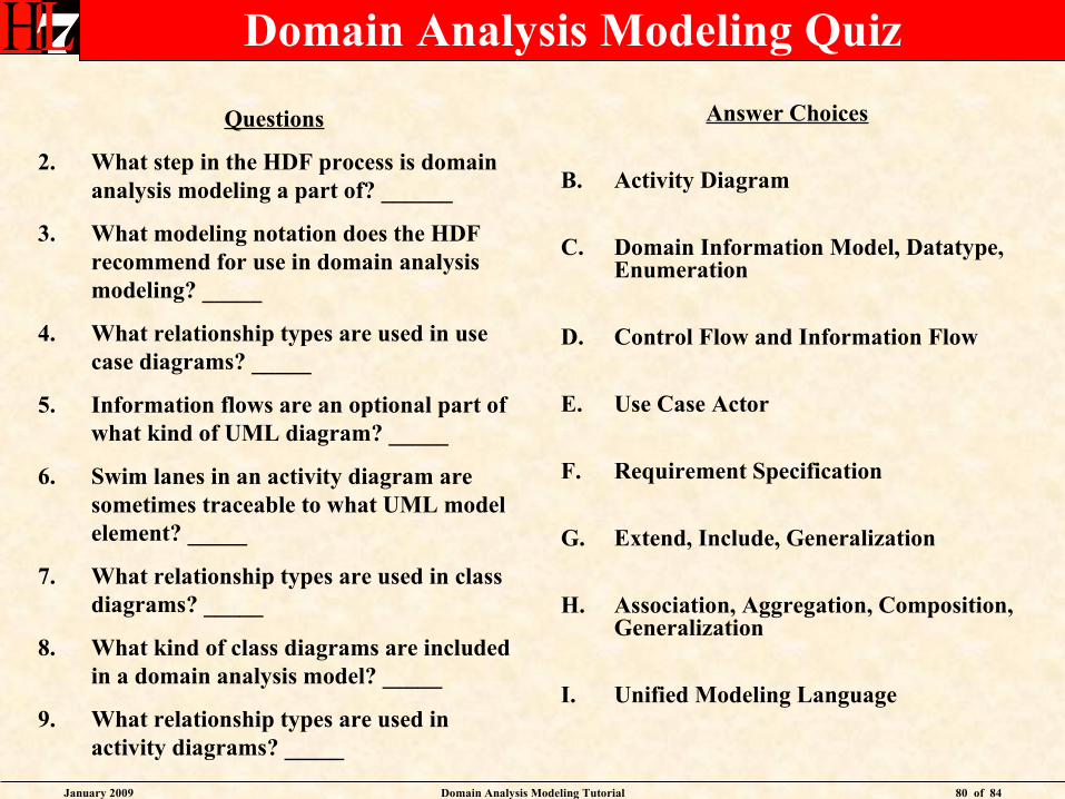
Domain Analysis Modeling Quiz
Questions
2. What step in the HDF process is domain analysis modeling a part of? ______
3. What modeling notation does the HDF recommend for use in domain analysis modeling? _____
4. What relationship types are used in use case diagrams? _____
5. Information flows are an optional part of what kind of UML diagram? _____
6. Swim lanes in an activity diagram are sometimes traceable to what UML model element? _____
7. What relationship types are used in class diagrams? _____
8. What kind of class diagrams are included in a domain analysis model? _____
9. What relationship types are used in activity diagrams? _____
Answer Choices
B. Activity Diagram
C. Domain Information Model, Datatype, Enumeration
D. Control Flow and Information Flow
E. Use Case Actor
F. Requirement Specification
G. Extend, Include, Generalization
H. Association, Aggregation, Composition, Generalization
I. Unified Modeling Language
January 2009 Domain Analysis Modeling Tutorial 81 of 84
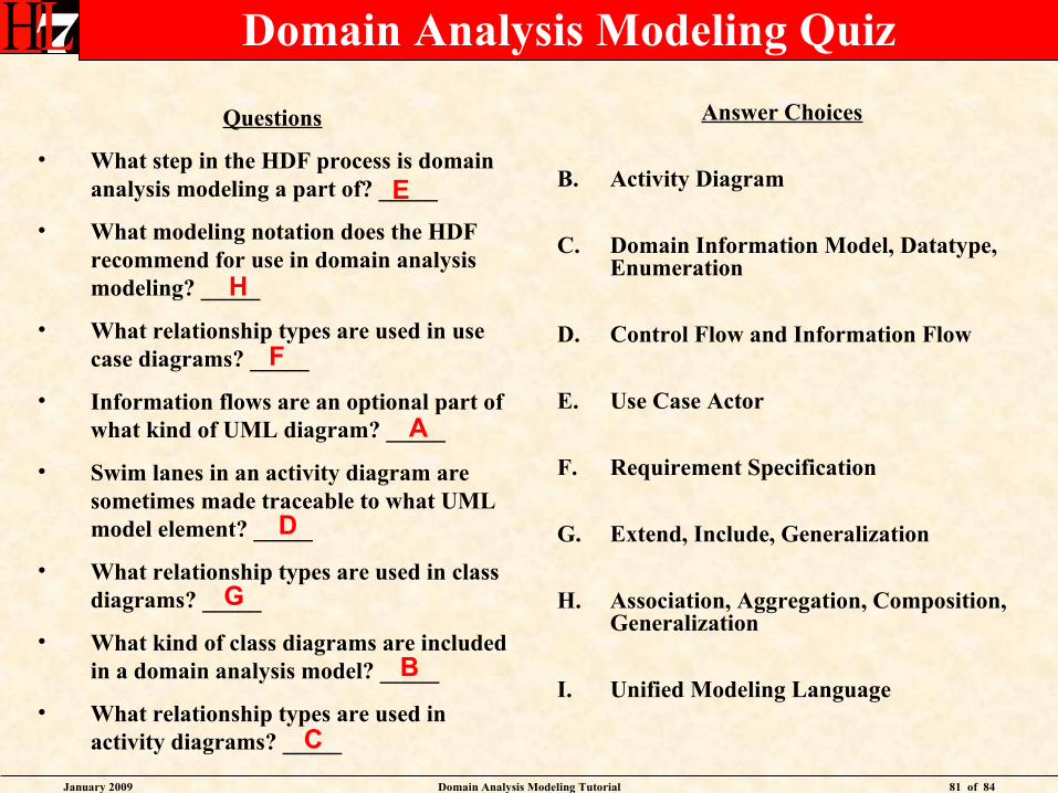
Domain Analysis Modeling Quiz
Questions
• What step in the HDF process is domain analysis modeling a part of? _____
• What modeling notation does the HDF recommend for use in domain analysis modeling? _____
• What relationship types are used in use case diagrams? _____
• Information flows are an optional part of what kind of UML diagram? _____
• Swim lanes in an activity diagram are sometimes made traceable to what UML model element? _____
• What relationship types are used in class diagrams? _____
• What kind of class diagrams are included in a domain analysis model? _____
• What relationship types are used in activity diagrams? _____
Answer Choices
B. Activity Diagram
C. Domain Information Model, Datatype, Enumeration
D. Control Flow and Information Flow
E. Use Case Actor
F. Requirement Specification
G. Extend, Include, Generalization
H. Association, Aggregation, Composition, Generalization
I. Unified Modeling Language
E
H
F
A
D
G
B
C
January 2009 Domain Analysis Modeling Tutorial 82 of 84
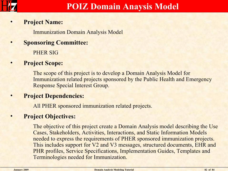
POIZ Domain Anaysis Model
• Project Name:
Immunization Domain Analysis Model
• Sponsoring Committee:
PHER SIG
• Project Scope:
The scope of this project is to develop a Domain Analysis Model for Immunization related projects sponsored by the Public Health and Emergency Response Special Interest Group.
• Project Dependencies:
All PHER sponsored immunization related projects.
• Project Objectives:
The objective of this project create a Domain Analysis model describing the Use Cases, Stakeholders, Activities, Interactions, and Static Information Models needed to express the requirements of PHER sponsored immunization projects. This includes support for V2 and V3 messages, structured documents, EHR and PHR profiles, Service Specifications, Implementation Guides, Templates and Terminologies needed for Immunization.
January 2009 Domain Analysis Modeling Tutorial 83 of 84
Questions / Discussion / Feedback
January 2009 Domain Analysis Modeling Tutorial 84 of 84
Thank You
Abdul-Malik ShakirPrincipal Consultant
Shakir Consulting1407 Foothill Blvd., Suite 145
La Verne, CA 91750
Office: (909) 596-6790 Mobile: (626) 644-4491Email: [email protected]