domain driven design - the hillside...
TRANSCRIPT

Domain Dr iven Design Tackling Complexity in the Heart of Business Software
Er ic Evans
[email protected] (415) 902-7873
(Draft August 7, 2002)
Excerpt for PLoP 2002 Full manuscript available at: http:// domainlanguage.com
Copyr i ght © 2002, Er i c Evans. Per mi ss i on i s gr ant ed t o copy f or t he PLoP 2002 conf er ence. Al l ot her r i ght s r eser ved.
(Draft August 7, 2002) © Eric Evans, 2002 2
Table of Contents Preface........................................................................................................................................................4
The Challenge of Complexity .................................................................................................................4 Design vs. Development Process............................................................................................................5 What Is in This Book...............................................................................................................................6 Who Should Read This Book..................................................................................................................7
1. Crunching Knowledge..................................................................................................................11 2. Communication.............................................................................................................................17
UBIQUITOUS LANGUAGE..................................................................................................................17 3. Path to Implementation................................................................................................................22
MODEL DRIVEN DESIGN ..................................................................................................................22 Map of High-Level Patterns..................................................................................................................31
OBJECT MODEL ...............................................................................................................................35
4. Isolating the Domain.....................................................................................................................37 ISOLATED DOMAIN LAYER ..............................................................................................................37 INFRASTRUCTURE LAYER ................................................................................................................37 MODEL-VIEW-CONTROLLER (MVC)...............................................................................................38 SMART UI ANTI-PATTERN ...............................................................................................................38
5. Expressing the Model....................................................................................................................41 ENTITIES..........................................................................................................................................42 VALUE OBJECTS..............................................................................................................................50 AGGREGATES...................................................................................................................................55
Designing Objects for Relational Databases.........................................................................................62 6. When I t Just Isn’ t a Thing...........................................................................................................64
SERVICES.........................................................................................................................................64 7. Access to Expressive Objects........................................................................................................68
REPOSITORIES..................................................................................................................................69 FACTORIES.......................................................................................................................................72
8. Chunking the Model .....................................................................................................................76 MODULES (AKA PACKAGES) ............................................................................................................76
9. Using the Foundation Language in an Example: A Cargo Shipping System ..........................79
10. Deep Modeling...............................................................................................................................96 11. Making Implicit Concepts Explicit ............................................................................................104
Expressing constraints explicitly.........................................................................................................111 12. Domain Patterns..........................................................................................................................113
POSITION-TRANSACTION ...............................................................................................................113 ADVANCER [WARD CUNNINGHAM] ...............................................................................................115 SPECIFICATION [EVANS & FOWLER 1997] .....................................................................................116 KNOWLEDGE LEVEL [FOWLER 1996] AKA REFLECTION................................................................127
Design Patterns vs. Domain Patterns...................................................................................................130 STRATEGY [GHJV95]....................................................................................................................131 COMPOSITE [GHJV95] ..................................................................................................................133
Why Not FLYWEIGHT?........................................................................................................................133

(Draft August 7, 2002) © Eric Evans, 2002 3
13. DECLARATIVE DESIGN.................................................................................................................135 14. Designing on an Agile Project ....................................................................................................142
Refactoring Toward Deeper Insight ....................................................................................................145
15. Maintaining Model Integr ity......................................................................................................148
UNIFICATION CONTEXT .................................................................................................................150 CONTINUOUS INTEGRATION...........................................................................................................158 SHARED KERNEL ...........................................................................................................................160 CUSTOMER/SUPPLIER DEVELOPMENT TEAMS .................................................................................161 CONFORMIST .................................................................................................................................163 SEPARATE WAYS...........................................................................................................................165 ANTICORRUPTION LAYER..............................................................................................................166 OPEN HOST SERVICE .....................................................................................................................170 PUBLISHED LANGUAGE..................................................................................................................170
Unifying an Elephant...........................................................................................................................172 Choosing Your UNIFICATION CONTEXT Strategy................................................................................174 Transformations..................................................................................................................................178
Merging CONTEXTS (SEPARATE WAYS SHARED KERNEL).......................................................178 Merging CONTEXTS (SHARED KERNEL CONTINUOUS INTEGRATION) ......................................179 Phasing Out a Legacy System.......................................................................................................180 OPEN HOST SERVICE PUBLISHED LANGUAGE...........................................................................181
16. Distillation....................................................................................................................................182 CORE DOMAIN...............................................................................................................................183 GENERIC SUBDOMAINS..................................................................................................................186 DOMAIN VISION STATEMENT ........................................................................................................191 HIGHLIGHTED CORE ......................................................................................................................192 COHESIVE MECHANISMS................................................................................................................195 DECLARATIVE DESIGN...................................................................................................................197 SEGREGATED CORE .......................................................................................................................198 ABSTRACT CORE ...........................................................................................................................204
Deep Models.......................................................................................................................................205 Refactoring and Distillation ................................................................................................................205
17. Large-Scale Structure.................................................................................................................206 EVOLVING ORDER .........................................................................................................................208 SYSTEM METAPHOR [BECK 2000] .................................................................................................209 PLUGGABLE COMPONENTS.............................................................................................................210 ABSTRACT DOMAIN FRAMEWORK .................................................................................................212 RESPONSIBILITY LAYERS...............................................................................................................212
Large-Scale Structure, Unification Contexts, and Distillation............................................................223 Refactoring Toward a Fitting Structure...............................................................................................225 Architecture, Architecture Teams, and Large-Scale Structure............................................................227
18. Game Plans..................................................................................................................................230
Looking Forward...................................................................................................................................231 Appendix 1: Pattern Summar ies..........................................................................................................232
REPOSITORY ..................................................................................................................................232 References..............................................................................................................................................233 Acknowledgements................................................................................................................................234
(Draft August 7, 2002) © Eric Evans, 2002 8
Part I . T he Role o f t he Dom ain Model
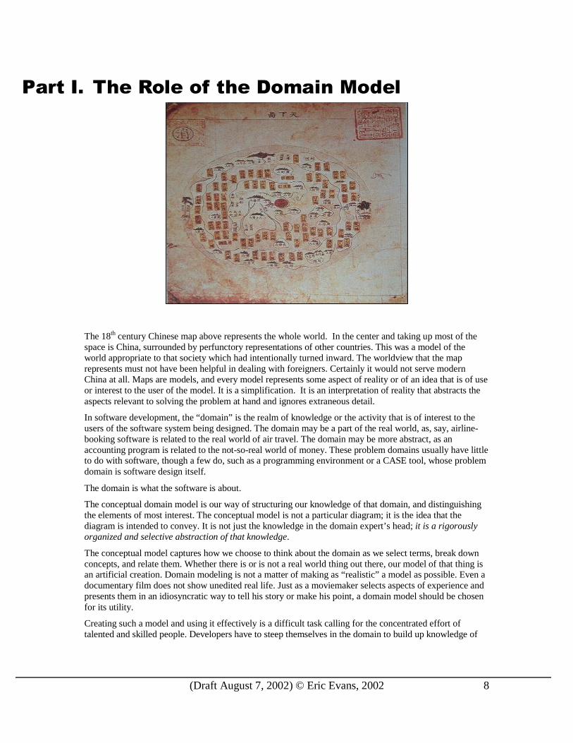
The 18th century Chinese map above represents the whole world. In the center and taking up most of the space is China, surrounded by perfunctory representations of other countries. This was a model of the world appropriate to that society which had intentionally turned inward. The worldview that the map represents must not have been helpful in dealing with foreigners. Certainly it would not serve modern China at all. Maps are models, and every model represents some aspect of reality or of an idea that is of use or interest to the user of the model. It is a simplification. It is an interpretation of reality that abstracts the aspects relevant to solving the problem at hand and ignores extraneous detail.
In software development, the “domain” is the realm of knowledge or the activity that is of interest to the users of the software system being designed. The domain may be a part of the real world, as, say, airline-booking software is related to the real world of air travel. The domain may be more abstract, as an accounting program is related to the not-so-real world of money. These problem domains usually have little to do with software, though a few do, such as a programming environment or a CASE tool, whose problem domain is software design itself.
The domain is what the software is about.
The conceptual domain model is our way of structuring our knowledge of that domain, and distinguishing the elements of most interest. The conceptual model is not a particular diagram; it is the idea that the diagram is intended to convey. It is not just the knowledge in the domain expert’s head; it is a rigorously organized and selective abstraction of that knowledge.
The conceptual model captures how we choose to think about the domain as we select terms, break down concepts, and relate them. Whether there is or is not a real world thing out there, our model of that thing is an artificial creation. Domain modeling is not a matter of making as “ realistic” a model as possible. Even a documentary film does not show unedited real life. Just as a moviemaker selects aspects of experience and presents them in an idiosyncratic way to tell his story or make his point, a domain model should be chosen for its utility.
Creating such a model and using it effectively is a difficult task calling for the concentrated effort of talented and skilled people. Developers have to steep themselves in the domain to build up knowledge of
(Draft August 7, 2002) © Eric Evans, 2002 9
the business. They must hone their modeling skills and master domain design. Any software project tackling complex business problems without a sharp focus on the domain model is at risk.
This is easy to lose sight of because technical people enjoy quantifiable technical problems that exercise their technical skills. The domain usually does not seem attractive. It is messy and demands a lot of complicated new knowledge that doesn’ t seem to develop a computer scientist’s capabilities. This does not have to be so. I hope that this book will show that domain design does hold technical challenges and opportunities to develop very sophisticated design skills. The messiness of most business domains is in fact the most interesting challenge. What it demands is the creation of a model that can cut through complexity. (Complexity is one of the most exciting current areas of research in several scientific disciplines, as researchers attempt to tackle the messiness of the real world.) Developing the techniques and the insight to make designs that make that complexity transparent is an exciting challenge.
Unfortunately, this is neither the perception nor the reality of most current software projects, so the strongest technical talent tends to get swept up in infrastructure, and other definable tasks. This is a great project risk.
In a TV talk show interview, comedian John Cleese told a story of an event during the filming of “Monty Python and the Holy Grail” . They had been shooting a particular scene over and over, but somehow it wasn’ t funny. Finally, he took a break and consulted with fellow comedian Michael Palin (the other actor in the scene), and they came up with a slight variation. They shot one more take, and it turned out funny, so they called it a day.
The next morning Mr. Cleese was looking at the rough cut the film editor had put together of the previous day’s work. Coming to the scene they had struggled with, he found that it wasn’ t funny; one of the earlier takes had been used.
He asked the film editor why he hadn’t used the last take, as directed. “Couldn’t use it. Someone walked in-shot,” he replied. Mr. Cleese watched the scene again, and then again. Still he could see nothing wrong. Finally the editor stopped the film and pointed out a coat sleeve that was visible for a moment at the edge of the picture.
The film editor was concerned that other film editors who saw the movie would judge his work based on its technical perfection. He was focused on the precise execution of his own specialty, and, in the process, the heart of the scene had been lost. [“The Late Late Show with Craig Kilborn” , CBS, September, 2001]
Fortunately, the funny scene was restored by a director who understood comedy. In just the same way, enthusiastic software developers will develop elaborate technical frameworks that do not serve, or actually get in the way of domain development. In just the same way, leaders within a team who understand the centrality of the domain can put their software project back on course. A team can build expertise in using the conceptual domain model and develop a focus that places the technical components of the system in perspective as vital supporting elements.
For a software development project, the most useful contributions of a domain model are:
• To capture knowledge, rigorously organized, unambiguous, and distilled (Chapter 1)
• To enhance communication through a shared language (Chapter 2)
• To provide a direct path to implementation and maintenance of functional software (Chapter 3)
When the domain is done right, the resulting software has a flexibility and power that otherwise can only be accomplished through massive amounts of ad hoc development. Yet most projects get very little out of their domain model. If a project does not benefit from its domain model it is because the model does not accomplish one or more of the three missions bulleted above.
This book will examine an array of potential obstacles to effective domain development, and ways of getting past those obstacles with design principles ranging from high-level concepts to concrete techniques.

(Draft August 7, 2002) © Eric Evans, 2002 10
The next three chapters set out to examine the meaning and value of each of these contributions in turn, and discuss some of the ways they are intertwined.
The Diagram is Not the Model
All too often, a UML diagram is used to mirror the exact implementation. Reverse engineering and code generation tools encourage this. Eventually, the UML diagram is merely another way to view the program itself, and the very meaning of “model” is lost.
The model is not the diagram. It is an abstraction, a set of concepts and relationships between them. A diagram can represent and communicate a model, as can carefully written code, as can an English sentence. All of these communication channels are needed to develop good models, create a shared understanding of them, and embed them deeply into the implementation and where they can provide leverage for all project activity. This is the aim of Domain Driven Design.
<<Perhaps show some simple model (with an action) as a diagram, code, and English description>>
One of the consequences of this notion of the diagram as a communication of the conceptual model is that the diagrams tend not to be detailed and comprehensive. The most useful model documents are intentionally incomplete. They distill a view of the model that emphasizes one important set of relationships or interactions and suppress distracting detail. You will find the diagrams in this book to be informal by some standards, omitting much detail and incorporating nonstandard notations. I strive for rigor in the form of tight abstractions that are logically cohesive and useful. Also, while the model and corresponding diagrams do not mirror the code, they are consistent with it in a way that is the subject of Chapter 3 and most of Part II. I assume that the code can communicate details of implementation and that other channels of communication, such as conversation, can fill in the details of the concepts themselves. So the diagrams and documents present the skeletons of ideas.
Many will resist this approach. There are those who believe in UML as an implementation language. Personally, I find Java more communicative of detail than UML, but that is beside the point. If you use UML as your implementation language, you will still need other means of communicating the uncluttered conceptual model.
Then there are those who are committed to formal rigor in conceptual models. I am very attracted to this approach, but I find that it too confining. Too little is known at the outset of most projects to develop such formal models, and the effort is not justified. Nor do most teams have the expertise to produce them. Occasionally, a formal model can be very useful, as will be discussed in several chapters, but it does not make a practical approach for the main stream of the development. Yet, while this philosophy does not provide a good goal, it does make a decent loadstar, an ideal to hold our models up to and move in the general direction of.
For the most part, we need some room to move with our models. They are imperfect. They evolve. They must be practical and useful. They should be rigorous enough to make the application simple to implement and understand.
(Draft August 7, 2002) © Eric Evans, 2002 31
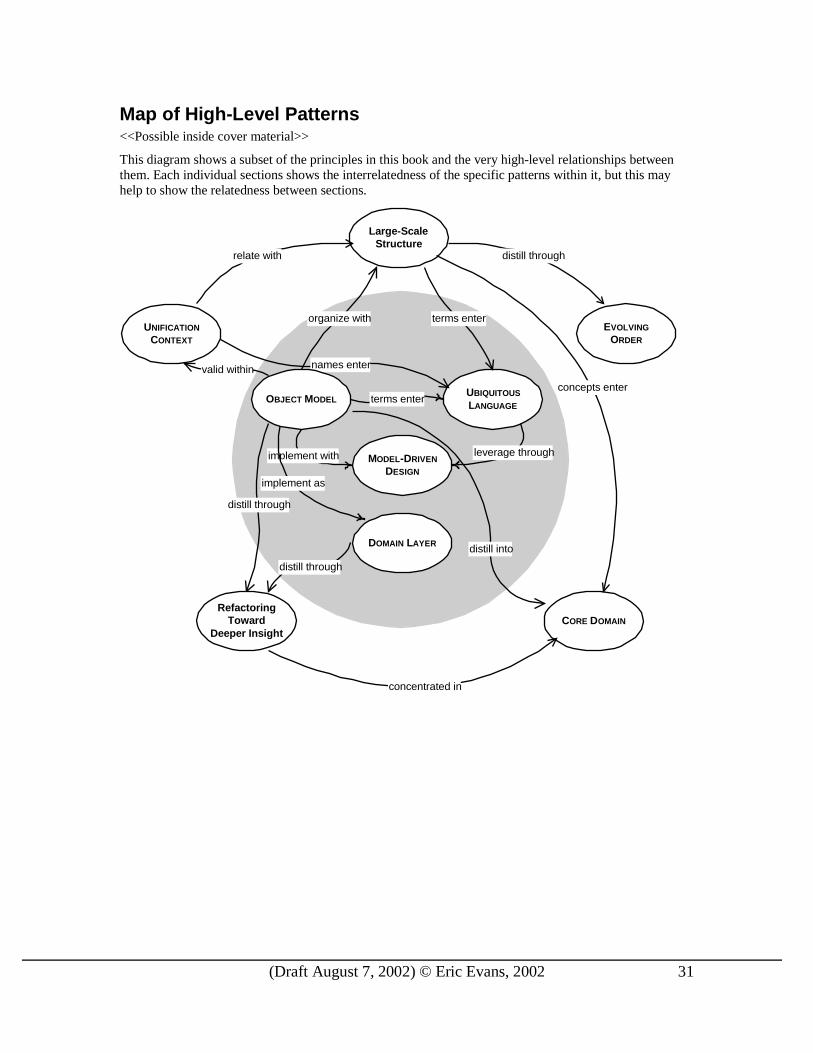
Map of High-Level Patterns <<Possible inside cover material>>
This diagram shows a subset of the principles in this book and the very high-level relationships between them. Each individual sections shows the interrelatedness of the specific patterns within it, but this may help to show the relatedness between sections.
distill into
terms enter
distill through
implement with
distill through
DOMAIN LAYER
MODEL-DRIVEN
DESIGN
UBIQUITOUS
LANGUAGE
Large-ScaleStructure
UNIFICATION
CONTEXT
RefactoringToward
Deeper InsightCORE DOMAIN
EVOLVING
ORDER
terms enter
distill through
organize with
valid within
relate with
implement as
leverage through
concepts enter
concentrated in
names enter
OBJECT MODEL

(Draft August 7, 2002) © Eric Evans, 2002 146
Part IV. St r at e g ic Des ign As systems grow too complex to know completely at the level of individual objects, we need techniques for manipulating and comprehending large models. This section presents principles that enable the modeling process to scale up to very complicated domains.
The goal of the most ambitious enterprise systems is a tightly integrated system spanning the entire business. Yet the entire business model for almost any such organization is too large and complex to manage or even understand as a single unit. The system must be broken into smaller parts, in both concept and implementation. The challenge is to accomplish this modularity without losing the benefits of integration, allowing different parts of the system to inter-operate to support the coordination of various business operations. A monolithic, spaghetti-like, all-encompassing domain model will be unwieldy and loaded with subtle duplications and contradictions. A set of small distinct subsystems glued together with ad-hoc interfaces will lack the power to solve enterprise wide problems, and allows consistency problems to arise at every integration point. The pitfalls of both extremes can be avoided with a systematic, evolving design strategy.
A good domain model captures an abstraction of the business in a form defined enough to be coded into software. Domain architecture must provide a guide to design decisions for the business model that reduce interdependence of parts and improve clarity and ease of understanding and analysis without reducing their interoperability and synergy. It must also capture the conceptual core of the system, the "vision" of the system. And it must do all this without bogging the project down. The three broad themes explored in this section can help accomplish these goals: UNIFICATION CONTEXT, DISTILLATION, and LARGE-SCALE
STRUCTURE.
UNIFICATION CONTEXT, the least obvious of the principles, is actually the most fundamental. A successful model, large or small, has to be logically consistent throughout, without any contradictory or overlapping definitions. Enterprise systems sometimes integrate subsystems with varying origins or have applications so distinct that very little in the domain is viewed in the same light. It may be asking too much to unify the conceptual models implicit in these disparate parts. By explicitly defining a UNIFICATION CONTEXT within which a model applies, and then, when necessary, defining its relationship with other contexts, the modeler can avoid bastardizing the model.
DISTILLATION reduces the clutter and focuses the attention appropriately. Often a great deal of effort is spent on peripheral issues in the domain. The overall domain model needs to make prominent the most value-adding and special aspects of your system and be structured to give that part as much power as possible. While some supporting components are critical, they must be put into their proper perspective. This not only helps to direct efforts toward vital parts of the system, but it keeps the vision of the system from being lost. DISTILLATION can bring clarity to an overall model. And with a clearer view the design of the core can be made more useful.
LARGE-SCALE STRUCTURE completes the picture. In a very complex model, you may not see the forest for the trees. Distillation helps, by focusing the attention on the core and presenting the other elements in their supporting roles, but the relationships can still be too confusing without some LARGE-SCALE STRUCTURE that allows system-wide design elements and patterns to be applied. I’ ll overview a few approaches to large scale structure and then go into depth on one such pattern, RESPONSIBILITY LAYERS, in which a small but powerful set of fundamental responsibilities are identified that can be organized into layers with defined relationships between layers, such as modes of communication and allowed references. These are examples of LARGE SCALE STRUCTURES, not a comprehensive catalog. New ones should be invented when needed. Some such structure can bring a uniformity to the design that can accelerate the design process and improve integration.
These principles, useful separately but particularly powerful taken together, help to produce good designs even when systems become too big to understand as a whole while simultaneously thinking about the detail level of individual objects. UNIFICATION CONTEXTS and LARGE-SCALE STRUCTURE can bring consistency to

(Draft August 7, 2002) © Eric Evans, 2002 147
the disparate parts to help those parts mesh. STRUCTURE and DISTILLATION make the complex relationships between the parts comprehensible while keeping the big picture in view.
(Draft August 7, 2002) © Eric Evans, 2002 148
15. Maintaining Model Integrity
I once worked on a project where several teams were working in parallel on a major new system. One day, the team working on the customer-invoicing module was ready to implement an object they called “Charge” , when they discovered that another team had already built one. Diligently, they set out to reuse the existing object. They discovered it didn’ t have an “expense code” , so they added one. It already had the “posted amount” attribute they needed. They had been planning to call it “amount due”, but what is in a name? They changed it. Adding a few more methods and associations, they got something that looked like what they wanted, without disturbing what was there. They had to ignore many associations they didn’ t need, but their application module ran.
A few days later, mysterious problems surfaced in the bill-payment application module for which the Charge had been originally written. Strange “Charges” appeared that no one remembered entering and which didn’ t make any sense. The program began to crash when some functions were used, particularly the month-to-date tax report. Investigation revealed that the crash resulted when a function was used that summed up the amount deductible for all the current month’s payments. The mystery records had no value in the “percent deductible” field, although the validation of the data entry application required it and even put in a default value.
The problem was that these two groups had different models, but they did not realize it, and there were no processes in place to detect it. Each made assumptions about the nature of a charge that were useful in their context (billing customers versus paying vendors). When their code was combined without resolving these contradictions, the result was unreliable software.
If only they had been more aware of this reality, they could have consciously decided how to deal with it. That might have meant working together to hammer out a common model and then writing an automated test suite to prevent future surprises. Or it might simply have meant an agreement to develop separate models and keep hands off each other’s code. Either way, it starts with an explicit agreement on the boundaries within which each model applies.
What did they do? They created separate Customer Charge and Supplier Charge classes and defined each according to the needs of the corresponding team. Then they went back to doing things just as before. Oh, well.
Although we seldom think about it explicitly, the most fundamental requirement of a model is that it be internally consistent; that every term always have the same meaning, and that it contain no contradictory rules. A model is meaningless unless it is logically consistent. In the ideal world, we would have a single conceptual model spanning the whole domain of the enterprise. This model would be unified, without any contradictory or overlapping definitions of terms. Every logical statement in the domain would be consistent. But the world of large systems development is not the ideal world. To maintain that level of unification in an entire system is often more trouble than it is worth. It is necessary to allow multiple models to develop in different parts of the system. But we need to make careful choices about which parts of the system diverge and what their relationship to each other will be. We need ways of keeping crucial parts of the model tightly unified. None of this happen by itself or through good intentions. It only happens through conscious design decisions and institution of specific processes.

(Draft August 7, 2002) © Eric Evans, 2002 149
Navigation Map for Model Integrity Patterns
UNIFICATION
CONTEXT
relate as
keep unified by
relate through
formalize relationship as
CONTINUOUS
INTEGRATION CUSTOMER/SUPPLIER
TEAMS
CONFORMIST
OPEN HOST
SERVICE
SEPARATE
WAYS
PUBLISHED
INTERCHANGE
LANGUAGE
SHARED KERNEL
relate as
free teams with
(Draft August 7, 2002) © Eric Evans, 2002 150
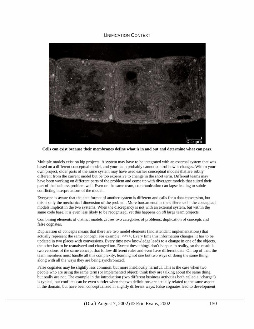
UNIFICATION CONTEXT
Cells can exist because their membranes define what is in and out and determine what can pass.
Multiple models exist on big projects. A system may have to be integrated with an external system that was based on a different conceptual model, and your team probably cannot control how it changes. Within your own project, older parts of the same system may have used earlier conceptual models that are subtly different from the current model but be too expensive to change in the short term. Different teams may have been working on different parts of the problem and come up with divergent models that suited their part of the business problem well. Even on the same team, communication can lapse leading to subtle conflicting interpretations of the model.
Everyone is aware that the data format of another system is different and calls for a data conversion, but this is only the mechanical dimension of the problem. More fundamental is the difference in the conceptual models implicit in the two systems. When the discrepancy is not with an external system, but within the same code base, it is even less likely to be recognized, yet this happens on all large team projects.
Combining elements of distinct models causes two categories of problems: duplication of concepts and false cognates.
Duplication of concepts means that there are two model elements (and attendant implementations) that actually represent the same concept. For example, <<>>. Every time this information changes, it has to be updated in two places with conversions. Every time new knowledge leads to a change in one of the objects, the other has to be reanalyzed and changed too. Except these things don’ t happen in reality, so the result is two versions of the same concept that follow different rules and even have different data. On top of that, the team members must handle all this complexity, learning not one but two ways of doing the same thing, along with all the ways they are being synchronized.
False cognates may be slightly less common, but more insidiously harmful. This is the case when two people who are using the same term (or implemented object) think they are talking about the same thing, but really are not. The example in the introduction (two different business activities both called a “charge”) is typical, but conflicts can be even subtler when the two definitions are actually related to the same aspect in the domain, but have been conceptualized in slightly different ways. False cognates lead to development

(Draft August 7, 2002) © Eric Evans, 2002 151
teams that step on each other’s code, databases that have weird contradictions, and confusion in communication within the team. The term “ false cognate” is ordinarily applied to natural languages. English speakers learning Spanish often misuse the word “embarasada” . This word does not mean “embarrassed”; it means “pregnant” . Oops.
Most people do recognize that having multiple models exacts a price in limited integration and less clear communication, and it somehow seems inelegant. Sometimes this leads to very ambitious attempts to unify all the software in a project under a single model. If this is taken too far it has costs too. For example:
1. Too many legacy replacements may be attempted at once.
2. Large projects may bog down because the coordination overhead exceeds their abilities.
3. Applications with specialized needs may have to use models that don’ t fully satisfy their needs, forcing them to put behavior elsewhere.
4. Conversely, attempting to satisfy everyone with a single model may lead to complex options that make the model difficult to use.
What’s more, model divergences are as likely to come from political fragmentation and differing management priorities as from technical concerns, so even when none of the factors above prevents integration, the project may still face multiple models.
You may be thinking that this is handled through the use of MODULES. True, when it is recognized that two sets of objects make up different models they are typically placed in separate MODULES, and this does provide different name-spaces that allow them to compile even if they have name overlaps. But this is just an implementation mechanism for code separation of different models. This issue is preceded by the fundamental problems, recognizing conceptual model differences and deciding what to do with them. Furthermore, MODULES are also used to organize the elements within one model, so they don’ t communicate an intention to separate conceptual models. The separate name-spaces they create can actually make it harder to spot accidental model divergences. While technical tools can help us communicate and implement conceptual issues, they don’ t solve our conceptual problems.
Total unification of the domain model for the entire system may not be feasible or cost-effective. Yet, when code based on distinct models is combined, software becomes buggy, unreliable, and difficult to understand. Communication among team members becomes confused.
Fortunately, this belongs to the class of problems for which a major part of the solution lies in simply seeing the problem. First we need some vocabulary to discuss the issue.
Model context: The context in which a model applies. This may be a certain part of the code, or a particular project. For a model invented in a brainstorming session, it could be a particular conversation. The context is whatever set of criteria you need to be able to say that the terms in a model have a specific meaning. For practical purposes, it can be thought of as a portion of the software system’s design.
Unification: Internal consistency of a model such that each term is unambiguous and no rules contradict.
Given those terms, we can define a new one.
Unification context: A bounded part of a software system design defined consciously by agreement of the team, within which a single model will apply and will be kept as unified as possible.
It isn't usually practical to maintain a unified model for an entire enterprise, but we don’ t have to be at the mercy of events. Through a combination of proactive decisions about what should be unified and pragmatic recognition of what is not unified, we can create a clear, shared picture of the situation. With that in hand, we can systematically set about making sure that the parts we want to unify stay that way, and the parts that are not unified don’ t cause confusion or corruption.
Therefore,
Draw boundar ies within the system that explicitly define one or more UNIFICATION CONTEXTS. Within each context work to keep the model logically unified, str ictly consistent, but between

(Draft August 7, 2002) © Eric Evans, 2002 152
CONTEXTS let there be differences in terminology, concepts and rules. By drawing an explicit boundary, you can keep each par t pure, and therefore potent, and at the same time avoid confusion when shifting your attention to other CONTEXTS. Integration across the boundaries necessarily will involve some translation, which you can analyze explicitly.
Name each UNIFICATION CONTEXT, and make the names part of the UBIQUITOUS LANGUAGE.
Model in Context
Model in Context
TranslationMap
Do not try to reuse objects between UNIFICATION CONTEXTS. Integration of functionality and data must go through a translation.
Within a UNIFICATION CONTEXT, you will have a coherent dialect of the UBIQUITOUS LANGUAGE. The names of the UNIFICATION CONTEXTS will themselves enter that LANGUAGE so that you can speak unambiguously about the model of any part of the design by making your CONTEXT clear.
Example: Two UNIFICATION CONTEXTS in a Shipping Application We return again to the shipping system. One of the application’s major features was to be automatic routing of cargos at booking time. The model was something like this:
origindestinationcustoms clearance (opt)
Route Specification
Itinerary
{ordered}
*
0..1
{Itinerary must satisfy specification}
Routing Servicea Route Specification
an Itinerary satisfyingthe Route Specification
Cargo
vessel Voyage IDload dateload locationunload dateunload location
Leg

(Draft August 7, 2002) © Eric Evans, 2002 153
The Router is a SERVICE that encapsulates a mechanism behind a declarative interface. The interface declares that:
1. When a Route Specification is passed in, an Itinerary will be returned. 2. The returned Itinerary will satisfy the Route Specification passed in.
Nothing is stated about how this very difficult task is performed. Now lets go behind the curtain to see the mechanism.
Initially, on this project, I was too dogmatic about the internals of the Router. I wanted the actual routing operation to be done with an extended domain model that would represent vessel voyages and directly relate them to the Legs in the Itinerary. But the team working on the routing problem pointed out that, to make it perform well and in order to draw on well established algorithms, it needed to be implemented as an optimized network with each leg of a voyage represented as an element in a matrix. They insisted that they needed a distinct model of shipping operations for this purpose.
They were clearly right about the computational demands of the routing process as then designed, and so, lacking any better idea, I yielded. In effect, we created two separate UNIFICATION CONTEXTS, each of which had its own conceptual organization of shipping operations.
vessel Voyage IDload dateload locationunload dateunload location
Leg
Itinerary
Transport NetworkCONTEXT
{ordered}
* route(RouteSpecificationspec):Itinerary
Routing Service
Booking CONTEXT
length
Arc
IDlocationCode
Node
*
origindestinationcustoms clearance (opt)
Route Specification
{Itinerary must satisfy specification}
findPath(ListlocationCodes) :List
Network TraversalService
from
Encapsulates a complicatedmathematical mechanism.
Output list of Nodes is a paththrough the network thatmust pass through the inputlist of locations.
*to11
vessel Voyage IDdateoperationType
ShippingOperation
from
Our requirement was to take a Routing Service request, translate it into terms the Graph Traversal Service could understand, then take the result and translate it into the form a Routing Service is expected to give.
This means it was not necessary to map everything in these two models, but only to be able to make two specific translations:

(Draft August 7, 2002) © Eric Evans, 2002 154
Route Specification List of location codes
List of Node IDs Itinerary
To do this, we have to look at the meaning of an element of one model and figure out how to express it in terms of the other.
Starting with the first (Route Specification List of location codes), we have to think about the meaning of the sequence of locations in the list. The first in the list will be the beginning of the path, which will then be forced to pass through each location in turn until it reaches the last location in the list. So the origin and destination are the first and last in the list, with the customs clearance location (if there is one) in the middle.
aRouteSpec.origin
aRouteSpec.customsClearance
aRouteSpec.destination
List
(Mercifully, the two teams used the same location codes, so we don’t have to deal with that level of translation.)
Notice that the reverse translation would be ambiguous, since the network traversal input allows any number of intermediate points, not just one specifically designated as customs clearance point. Fortunately, this is no problem because we don’t need to translate in that direction, but it gives a glimpse of why some translations are impossible.
Now, let’s do result translation (List of Node IDs Itinerary). We’ll assuming we can use a REPOSITORY to look up the Node and Shipping Operation objects based on the Node IDs we receive. So, how do those Nodes map to Legs? Based on the oper at i onTypeCode, we can break the list of Nodes into departure/arrival pairs. Each pair then relates to one Leg.
ListNode
Node
Node
Node
Node
Node
depart
depart
depart
arrive
arrive
arrive
Leg
Leg
Leg
Itinerary
The attributes for each Node pair would be mapped as:
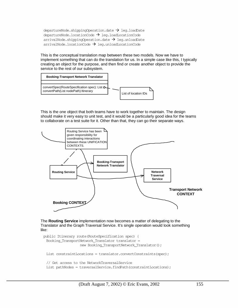
depar t ur eNode. shi ppi ngOper at i on. vessel VoyageI d l eg. vessel VoyageI d
(Draft August 7, 2002) © Eric Evans, 2002 155
depar t ur eNode. shi ppi ngOper at i on. dat e l eg. l oadDat e depar t ur eNode. l ocat i onCode l eg. l oadLocat i onCode ar r i val Node. shi ppi ngOper at i on. dat e l eg. unl oadDat e ar r i val Node. l ocat i onCode l eg. unl oadLocat i onCode
This is the conceptual translation map between these two models. Now we have to implement something that can do the translation for us. In a simple case like this, I typically creating an object for the purpose, and then find or create another object to provide the service to the rest of our subsystem.
convertSpec(RouteSpecification spec): ListconvertPath(List nodePath):Itinerary
Booking-Transport Network Translator
List of location IDs
This is the one object that both teams have to work together to maintain. The design should make it very easy to unit test, and it would be a particularly good idea for the teams to collaborate on a test suite for it. Other than that, they can go their separate ways.
Transport NetworkCONTEXT
Booking CONTEXT
Routing Service has beengiven responsibility forcoordinating interactionsbetween these UNIFICATIONCONTEXTS.
Routing Service
Booking-TransportNetwork Translator
NetworkTraversalService
The Routing Service implementation now becomes a matter of delegating to the Translator and the Graph Traversal Service. It’s single operation would look something like:
publ i c I t i ner ar y r out e( Rout eSpeci f i cat i on spec) { Booki ng_Tr anspor t Net wor k_Tr ansl at or t r ansl at or =
new Booki ng_Tr anspor t Net wor k_Tr ansl at or ( ) ; Li st const r ai nt Locat i ons = t r ansl at or . conver t Const r ai nt s( spec) ; / / Get access t o t he Net wor kTr aver sal Ser vi ce Li st pat hNodes = t r aver sal Ser vi ce. f i ndPat h( const r ai nt Locat i ons) ;

(Draft August 7, 2002) © Eric Evans, 2002 156
I t i ner ar y r esul t = t r ansl at or . conver t ( pat hNodes) ; r et ur n r esul t ; }
Not bad. The distinct UNIFICATION CONTEXTS served to keep each of the models relatively clean, let the teams work largely independently, and, if initial assumptions had been correct, would probably have served well. (We’ll return to that later in this chapter.)
The interface between the two contexts is fairly small. The declarative interface of the Routing Service insulates the rest of the Booking CONTEXT’s design from events in the route finding world. Both of these characteristics make the interface easy to test. One of the secrets to comfortable coexistence with other CONTEXTS is to have effective sets of tests for the interfaces. “Trust, but verify,” said President Reagan when negotiating arms reductions.
It should be easy to devise a set of automated tests that would feed Route Specifications into the Router and check the returned Itinerary.
Recognizing Splinters Within a Unification Context
<<many symptoms may indicate unrecognized model differences…
confusion of language, groups who want to pull model in different directions for good reasons,
>>
Testing the Boundaries
Contact points with other UNIFICATION CONTEXTS are particularly important to test because this helps compensate for the subtleties of translation and the lower level of communication that typically exists. It is a valuable early warning system, especially reassuring in cases where you depend on details of a model you don’ t control.
Organizing and Documenting Unification Contexts
There are only two important points here:
1. The UNIFICATION CONTEXTS should have names so that you can talk about them. Those names should enter the UBIQUITOUS LANGUAGE of the team.
2. Everyone has to know where the boundaries lie including being able to recognize the CONTEXT of any piece of code.
The second requirement could be met in many ways depending on the culture of the team. Once the UNIFICATION CONTEXTS have been defined, it comes naturally to segregate the code of different CONTEXTS into different MODULES, which leaves the question of how to keep track of which MODULE belongs in which CONTEXT. A naming convention might be used to indicate this, or any other mechanism that is easy and avoids confusion.
Equally important is communicating the conceptual boundaries in such a way that everyone on the team understands them the same way. For this communication purpose, I like informal diagrams like the ones in the example. More rigorous diagrams or textual lists could be made showing all packages in each CONTEXT along with the points of contact and the mechanisms responsible for connecting and translating. Some teams will be more comfortable with this approach, while others will get by fine based on verbal agreement and lots of discussion.
In any case, working the UNIFICATION CONTEXTS into discussions is essential if it is to enter the UBIQUITOUS LANGUAGE. Don’t say, “George’s team’s stuff is changing so we’re going to have to change

(Draft August 7, 2002) © Eric Evans, 2002 157
our stuff that talks to it.” Say instead, “The Transport Network model is changing so we’re going to have to change the translator for the Booking context.”
♦ ♦ ♦
Model contexts always exist, but may overlap and fluctuate. By explicitly defining UNIFICATION CONTEXTS your team can begin to direct the process of unifying models and connecting distinct ones.
This leaves the questions of where to draw them and how to maintain them.
Choosing the Boundaries
There are an unlimited variety of situations and an unlimited number of options for drawing the boundaries of the UNIFICATION CONTEXTS. But typically the struggle is to balance some subset of these forces:
Favoring Larger UNIFICATION CONTEXTS
• Improves flow between user tasks
• It is easier to understand one coherent model than two distinct ones plus mappings
• Translation between two models can be difficult (sometimes impossible)
• Shared language fosters clear team communication
Favoring Smaller UNIFICATION CONTEXTS
• Reduces communication overhead between developers
• Requires less of the disciplined processes needed to maintain model consistency
• Larger contexts may call for more versatile abstract models, requiring skills that are in short supply
• Different models can cater to special needs or encompass the jargon of specialized groups of users
Deep integration of functionality between different UNIFICATION CONTEXTS is impractical. Integration is limited to those parts of one model that can be rigorously stated in terms of the other model, and even this level of integration may take a considerable effort. This makes sense when there will be a small interface between two systems.
The following set of patterns cover some of the most common and important cases, which should give a good idea of how to approach other cases. When crack teams work closely on a tightly integrated product you can employ CONTINUOUS INTEGRATION, while the need to serve different user communities or a limitation on the coordination abilities of the team might adopt a SHARED KERNEL or set up CUSTOMER-SUPPLIER relationships. Sometimes a good hard look at the requirements reveals that integration is not essential and it is best for systems to go their SEPARATE WAYS. And, of course, most projects have to integrate to some degree with legacy and external systems, which can lead to OPEN HOST SERVICES or ANTICORRUPTION LAYERS…

(Draft August 7, 2002) © Eric Evans, 2002 158
CONTINUOUS INTEGRATION
…Once a UNIFICATION CONTEXT has been defined, we must keep it sound.
Whether we attack our system as a single unified model, or we break our systems into multiple UNIFICATION CONTEXTS, there are models we have to keep unified. Typically at least one or two of those pieces will be larger than the work of one person and will be taken on by a team.
When a number of people are working on the same system, within the same UNIFICATION CONTEXT, there is a strong tendency for the model to fragment. Sometimes developers do not fully understand the intent of some object or interaction modeled by someone else, and they change it in a way that makes it unusable for its or iginal purpose. Sometimes they don’ t realize that the concepts they are working on are already embodied in another part of the model and they duplicate (inexactly) those concepts and behavior . Sometimes they are aware of those other expressions, but are afraid to tamper with them, for fear of cor rupting the existing functionality, and so they proceed to duplicate concepts and functionality. The bigger the team, the more the problem. As few as three or four people can encounter ser ious problems. Yet most projects cannot succeed with only three developers, and breaking down the system into ever-smaller contexts eventually loses a valuable level of integration and coherency.
In essence, it is very hard to maintain the level of communication needed to develop a unified system of any size. We need ways of increasing communication and reducing complexity. We also need safety nets that prevent overcautious behavior, like developers duplicating functionality because they are afraid they will break existing code.
It is in this environment that Extreme Programming (XP) really comes into its own. Many of the XP practices are aimed at this specific problem of maintaining a coherent design that is being constantly changed by many people. This makes XP a perfect fit for maintaining model integrity within a single UNIFICATION CONTEXT. (And before people get excited, I’m not saying this is XP’s only application!) Whether or not the project employs all of XP, some of the practices are particularly relevant to this problem.
Some XP practices make specific enhancements to team communication (along with other benefits).
• Continuous integration
• Shared code ownership
• Pair programming

(Draft August 7, 2002) © Eric Evans, 2002 159
Other practices aim to make a model/design that is easier to communicate and maintain.
• Communicative Design
• Automated testing
Which I would supplement with patterns of this book aimed at communicating through the design.
• MODEL DRIVEN DESIGN
• Distillation (which will be taken up in Chapter ##)
And bridging design and team interaction is
• UBIQUITOUS LANGUAGE
Most of the principles of this book are driving toward this point of creating expressive, easily understood models that provide a language for the project and the backbone of the design.
Therefore,
Institute a process that includes SHARED CODE OWNERSHIP, CONTINUOUS INTEGRATION, and AUTOMATED TESTING. Spread knowledge even more by PAIR PROGRAMMING and swapping pairs frequently. Make the design itself more communicative through DISTILLATION and M ODEL DRIVEN
DESIGN and by applying all the design pr inciples of this book to make the model expressive. Relentlessly exercise your UBIQUITOUS LANGUAGE.
Finally, stay aware of the boundaries of the UNIFICATION CONTEXT and do not make the job any bigger than it has to be by combining the design issues of neighboring CONTEXTS. Instead, keep the design of each CONTEXT in it own mental box, and take up the design of translation layers between CONTEXTS as distinct tasks as well.
♦ ♦ ♦
CONTINUOUS INTEGRATION would be applied within any individual UNIFICATION CONTEXT that is larger than a two-person task.
CONTINUOUS INTEGRATION maintains the integrity of an individual UNIFICATION CONTEXT. When multiple UNIFICATION CONTEXTS coexist, you have to decide on their relationships and design any necessary interfaces…

(Draft August 7, 2002) © Eric Evans, 2002 160
SHARED KERNEL
TranslationMap
shared
… When functional integration is limited, the overhead of CONTINUOUS INTEGRATION may be deemed too high. This may especially be true when the teams do not have the skill or the political organization to maintain continuous integration, or when a single team is simply too big and unwieldy. So separate unification contexts might be drawn and multiple teams formed.
Uncoordinated teams working on closely related applications can go racing forward for a while, but what they produce may not fit together . They can end up spending more on translation layers and retrofitting than they would have on CONTINUOUS INTEGRATION in the first place, meanwhile duplicating effort and losing the benefits of a common UBIQUITOUS LANGUAGE.
On many projects I’ve seen the infrastructure layer shared among teams that worked largely independently. An analogy to this can work well within the domain as well. It may be too much overhead to fully synchronize the entire model and code base, but a carefully selected subset can provide much of the benefit for less cost.
Therefore,
Designate some subset of the domain model that the two teams agree to share. Of course this includes, along with this subset of the conceptual model, the subset of code or of the database design associated with that par t of the model. Integrate a functional system at each minor release point (at least weekly) at which point both teams can run their own acceptance tests. This explicitly shared stuff has special status, and shouldn’ t be changed without consultation with the other team.
It is a careful balance. The SHARED KERNEL cannot be changed as freely as other stuff. Decisions involve consultation with another team. Automated test suites must be integrated because all tests of both teams must pass when changes are made. Usually, teams make changes on separate copies of the KERNEL, integrating with the other team at intervals (at least weekly, as mentioned above). As usual, communication is a good thing, and the sooner both teams talk about the changes the better.
The SHARED KERNEL is often the CORE DOMAIN (p#) and/or some set of GENERIC SUBDOMAINS (p#), but it can be any part of the model that is needed by both teams. The goal is to reduce duplication (but not to eliminate it, as with CONTINUOUS INTEGRATION) and make integration between the two subsystems relatively easy.
<<Example: LS/2’s batch accruals?>>

(Draft August 7, 2002) © Eric Evans, 2002 161
CUSTOMER/SUPPLIER DEVELOPMENT TEAMS
… Often functionality is partitioned such that one subsystem essentially feeds another, while the second performs analysis or other functions that don’t feed back into the first very much. It is also common in these cases that the two subsystems serve very different user communities, with different jobs, where different models may be useful. The tool set may also be completely different, meaning that program code cannot be shared.
♦ ♦ ♦
Upstream and downstream subsystems, where the downstream component takes the output from the upstream component and all dependencies go one way, separate naturally into two UNIFICATION CONTEXTS. Translation is easier for having to operate in one direction only. This is especially true when the two components require different skills or employ a different tool set for implementation. But there are problems that can emerge in this situation, depending on the political relationship of the two teams.
The freewheeling development of the upstream team can be cramped if the downstream has veto power over changes or if procedures for requesting changes are too cumbersome. The upstream team may even be inhibited by worr ies of breaking the downstream system. Meanwhile, the downstream team can be helpless, at the mercy of upstream pr ior ities.
Downstream needs things from upstream, but upstream is not responsible for downstream deliverables. It takes a lot of extra effort to anticipate what will affect the other team, and human nature being what it is, and time pressures being what they are, well… It makes everyone’s life easier to formalize the relationship between the teams and organize the system for balancing the needs of the two user communities and scheduling work on features needed downstream.
On an Extreme Programming project, there already is a mechanism in place for doing just that: the iteration planning process. All we have to do is define the relationship between the two teams in the terms of the planning process. Representatives of the downstream team can function much like the user representatives, joining them in planning sessions, discussing the tradeoffs for the tasks they want directly with the other customers. The result is an iteration plan for the supplier team that includes tasks the downstream team most needs or defers tasks by agreement, so there is no expectation of delivery.
If a process other than XP is used, whatever analogous method is used to balance the concerns of different users can be expanded to include the downstream application’s needs.
Therefore,
Establish a clear customer/supplier relationship between the two teams. In planning sessions, make the downstream team play the customer role to the upstream team. Negotiate and budget tasks for downstream requirements so that everyone understands the commitment and schedule.
Jointly develop automated acceptance tests that will validate the interface they expect. Add these tests to the upstream team’s test suite to be run as part of their continuous integration. This will free the upstream team to make changes without fear of side effects downstream.

(Draft August 7, 2002) © Eric Evans, 2002 162
During the iteration, the downstream team members need to be available to the upstream developers just as the conventional customer is, to answer questions and help resolve problems.
Automating the acceptance tests is a vital part of this customer relationship. Even on the most cooperative project without tests, though the customer can identify its dependencies and communicate them, and the supplier tries to communicate changes, surprises will happen that will disrupt the downstream team’s work and force the upstream to take on unscheduled emergency fixes. Instead, have the customer team, in collaboration with the supplier team, develop automated acceptance tests that will validate the interface they expect. The upstream team will run these tests as part of their standard test suite. Any change to these tests calls for communication, since it implies change in interface.
I’ve also seen customer/supplier relationships emerge between projects in separate companies, in situations where a single customer is very important to the business of the supplier. Then the tail can wag the dog and get what they need. Both parties can benefit from the formalization of the process, since the cost/benefit tradeoffs are even harder to see than with the internal customers in the internal IT situation.
There are two crucial elements to this pattern.
1. The relationship must be that of customer and supplier, with the implication that the customer’s needs are paramount. Since the downstream application is not the only customer, their needs will have to be balanced, but they are still priorities. This is in contrast to the poor cousin relationship that often emerges, where the downstream has to come begging to the upstream team for their needs.
2. There needs to be an automated test suite that can give the upstream team the ability to change their code without fear of breaking the downstream, and lets the downstream team concentrate on their own work without constantly monitoring the upstream team.
In a relay race, the forward runner can’ t be looking behind himself all the time, checking. He or she has to be able to trust the baton carrier to make the handoff precisely, or the team will be hopelessly slowed down.
Example: Yield Analysis vs. Booking Back to our trusty shipping example. A highly specialized team has been set up analyze the all the bookings that flow through to see how to maximize income. They might find that ships have empty space and recommend overbooking more. They might find that the ships are filling up with bulk freight early, forcing the company to turn away more lucrative specialty cargos, and recommend reserving space for these, or recommend raising prices on the bulk freight.
To do this analysis, they use their own complex models. For implementation, they use a data warehouse with tools for building analytical models. And they need lots of information from the booking application.
From the start, it is clear that these are two UNIFICATION CONTEXTS, since they use different implementation tools, and, most importantly, different conceptual models. What should the relationship be between them?
A SHARED KERNEL might seem logical, since yield analysis is interested in a subset of the booking’s model, and their own model has some overlapping concepts of cargos, prices, etc. But SHARED KERNEL is difficult in a case where different implementation technologies are being used. Besides, the modeling needs of the yield analysis team are quite specialized, and they continuously play with their models and try alternative ones. They would really be better off translating what they need from the booking CONTEXT into their own. (On the other hand, if they can use a SHARED KERNEL, their translation burden will be much lighter. They will still have to reimplement the model and translate the data to the new implementation, but if the conceptual model is the same, the transfer should be simple.)

(Draft August 7, 2002) © Eric Evans, 2002 163
The booking application has no dependency on the yield analysis, since there is no intention of automatically adjusting policies. Human specialists will make the decisions and convey them to the needed people and systems. So we have an upstream/downstream relationship. What they need is:
1. Some data not needed by any booking operation
2. Some stability in database schema (or at least reliable notification of change) or an export utility.
Fortunately, the project manager of the booking application development team is motivated to help the yield analysis team. This could have been a problem, since the operations department that actually does day-to-day booking reports to a different vice president than the people who actually do yield analysis. But the upper management cares deeply about yield management and, having seen past cooperation problems between the two departments, structured the software development project so that the project managers of both teams report to the same person.
Therefore, all the requirements are in place to apply CUSTOMER/SUPPLIER DEVELOPMENT
TEAMS.
I’ve seen this scenario evolve in multiple places, where analysis software developers and operations software developers had a customer-supplier relationship. When the upstream thought of their role as serving a customer, things worked out pretty well. It was almost always organized informally, and in each case it worked out about as well as the personal relationship of the two project managers.
On one XP project, I saw this formalized in the sense that, each iteration, representatives of the downstream team played the ”planning game” in the role of customers, huddling with the more conventional customer representatives (of application functionality) to negotiate which tasks made it into the iteration plan. This project was at a small company, and so the nearest shared boss was not far up the chain.
♦ ♦ ♦
CUSTOMER/SUPPLIER TEAMS are more likely to work if the two teams work under the same management so that ultimately they do share goals, or where they are in different companies that actually have those roles. When there is nothing to motivate the upstream team, the situation is very different…
CONFORMIST When two teams with an upstream/downstream relationship are not effectively being directed from the same source, such a cooperative pattern as CUSTOMER/SUPPLIER TEAMS is not going to work, and naively trying to apply it will get the downstream team into trouble. This can be the case in a large company in which the two teams are far apart in the hierarchy or where the shared management level is indifferent to the relationship of the two teams. It can also arise when the two teams are in different companies where the downstream team’s company really is a customer to the upstream team’s company, but where that particular customer is not individually important to the supplier (because they are large with many customers, or because they are changing market direction and no longer value the old customers, or just because they are poorly run, or even out of business.) Whatever the reason, the reality is, the downstream is on its own.
When two development teams have an upstream/ downstream relationship in which the upstream has no motivation to provide for the downstream team’s needs, the downstream team is helpless. Altruism may lead upstream developers into making promises, but they are unlikely to be fulfilled. Belief in those good intentions leads the downstream team to make plans based on features that will

(Draft August 7, 2002) © Eric Evans, 2002 164
never be available. Their project will be delayed until they ultimately learn to live with what they are given.
In this situation, there are three possible paths. One is to abandon use of the upstream altogether. This should be evaluated realistically, making no assumptions that the upstream will accommodate them. Sometimes we overestimate the value or underestimate the cost of such a dependency. If the downstream team decides to cut the strings, they are going their SEPARATE WAYS, and no longer are a CONFORMIST.
I f the value is so great that the dependency on the upstream software must be maintained, then consider eliminating the complexity of translation between unification contexts by slavishly adhering to the conceptual model of the upstream team. This cramps the style of the downstream designers. I t probably is not going to be the ideal model for the application. But it is a huge reduction in complexity. Plus, you will share a ubiquitous language with your supplier team. This is good, since they are in the dr ivers seat, and altruism may be sufficient to get them to share information with you.
This decision deepens the dependency, and limits your application to the capabilities of the upstream model plus purely additive enhancements. It is very unappealing emotionally, which is why we choose it less than we probably should.
If these tradeoffs are not acceptable, but the upstream dependency is indispensable, the third option is to insulate yourself as much as possible by creating an ANTICORRUPTION LAYER, an aggressive approach to implementing a translation map that will be discussed later.
Example: Dragged Into Better Design Following isn’t always bad.
When using an off-the-shelf component that has a large interface, you should typically conform to the model implicit in that component. In other words, the UNIFICATION CONTEXT that integrates with the component should be unified with the context of the component. Even though adapters may be needed for minor format changes, the conceptual model should be equivalent. Otherwise, you should question the value of having the component. If it is good enough to give you value, there is probably knowledge crunched into its design. There must be more to your model than this one thing, and those parts you evolve.
<< concrete example >>
When your interface with a component is small, sharing a UNIFICATION CONTEXT is less essential, and translation is a viable option. But when integration is more extensive, it usually makes sense to follow the leader.
FOLLOW THE LEADER resembles SHARED KERNEL in that they both have an overlapping area where the model is the same, areas where you have extended your model by addition and areas where the other model does not affect you. The difference between the patterns is in the decision making process and development process. Where the SHARED KERNEL is a collaboration between two teams that coordinate tightly, FOLLOW THE LEADER DEALS with integration with a team that is not interested in collaboration.
♦ ♦ ♦
There is overhead of any integration, from full-on CONTINUOUS INTEGRATION inside a single UNIFICATION
CONTEXT, through the lesser commitments of SHARED KERNELS or CUSTOMER/SUPPLIER DEVELOPER TEAMS, to the one-sidedness of the CONFORMIST. Integration can be very valuable, but it is always expensive. We should be sure it is really needed…
(Draft August 7, 2002) © Eric Evans, 2002 165
SEPARATE WAYS
… Although integration can have great benefits (to the efficiency of development as well as to users) it can also be expensive. We must always be ruthless when it comes to defining requirements. If two sets of functionality have no significant relationship, they can be completely cut loose from each other.
Problem:
Solution:
Example: An Insurance Project Slims Down One project had set out to develop new software for insurance claims that would integrate everything a customer service agent or a claims-adjuster needed into one system. After a year of effort they were stuck. A combination of analysis paralysis with a major upfront investment in infrastructure had found them with nothing to show an increasingly impatient management. More seriously, the scope of what they were trying to do was overwhelming them. A new project manager forced everyone into a room for a week to form a new plan. First they made lists of requirements and tried to estimate their difficulty and assign importance. They ruthlessly chopped the difficult and unimportant ones. Then they started to bring order to the remaining list.
Many smart decisions were made in that room that week, but in the end, only one turned out to be important. At some point it was recognized that there were some features for which integration provided little added value. For example, adjusters needed access to some existing databases, and they had their current way of accessing them was very inconvenient. But, although the users needed to have this data, none of the other features of the proposed software system would use it.
Team members proposed various ways of providing easy access. In one case, a key report could be exported to html and placed on the intranet. In another case, adjusters could be provided with a specialized query written using a standard software package. All these functions could be integrated by organizing links on an intranet page or by placing buttons on the user’s desktop.
The team launched a set of small projects that attempted no more integration than launching from the same menu. Several needed capabilities were delivered almost overnight. Dropping the baggage of these extraneous features left a distilled set of requirements that seemed for a while to give hope for delivery of the main application.

(Draft August 7, 2002) © Eric Evans, 2002 166
It could have gone that way, but unfortunately the team slipped back into old habits. They paralyzed themselves again. In the end, their only legacy turned out to be those small applications that had gone their SEPARATE WAYS.
♦ ♦ ♦
SEPARATE WAYS forecloses some options. Although continuous refactoring can eventually undo anything, if integration is required after all, translation layers between multiple CONTEXTS will probably be necessary.
ANTICORRUPTION LAYER
…New systems almost always have to be integrated with legacy or other systems that will have their own models. When control or communication is not adequate to pull off a SHARED KERNEL or CUSTOMER/SUPPLIER DEVELOPMENT TEAMS, the interface can become more complex. Translation layers can be simple, even elegant, when bridging well-designed unification contexts with cooperative teams. But when the other side of the boundary starts to leak through, the translation layer may take on a different tone.
When a new system is being built that must have a large inter face with another , the difficulty of relating the two models can eventually overwhelm the intent of the new model altogether , causing it to be modified to resemble the other system’s model, in an ad hoc fashion. The models of legacy systems are usually weak, and even the exception that is well developed may not fit the needs of the cur rent project. Yet there may be a lot of value in the integration, and sometimes it is an absolute requirement.
The answer is not to avoid all integration with other systems. I’ve been on projects where people’s enthusiastically set out to replace all the legacy, but this is just too much to take on at once. Besides, integrating with existing systems is a valuable form of reuse. On a large project, one subsystem will often

(Draft August 7, 2002) © Eric Evans, 2002 167
have to interface with several other, independently developed subsystems. These will reflect the problem domain differently. When systems based on different models are combined, the need for the new system to adapt to the semantics of the other system can lead to a corruption of the new system’s own model. Even when the other system is well designed, it is not based on the same model as the client. And often the other system is not well designed.
There are many hurdles in interfacing with an external system. For example, the infrastructure layer must provide the means to communicate with another system that might be on a different platform or use different protocols. The data types of the other system must be translated into those of your system. But often overlooked is the certainty that the other system does not use the same conceptual domain model.
It seems clear enough that errors will result if you take some data from one system and misinterpret it in another. You may even corrupt the database. But even so, this problem tends to sneak up on us because we think that what we are transporting between systems is primitive data whose meaning is unambiguous and must be the same on both sides. This is usually wrong. Subtle yet important differences in meaning arise from the way the data are associated in each system. And even if some of the primitive data elements do have exactly the same meaning, it is a usually a mistake to make the interface to the other system operate at such a low level. A low-level interface looses the power of whatever conceptual model the other system has to explain the data and constrain its values and relationships, while saddling the new system with the burden of interpreting primitive data that is not in terms of to its own model.
So, combining systems with different models has pitfalls, but it is nonetheless unavoidable.
A means is needed to provide a translation between the parts that adhere to different models, so that the models are not corrupted with undigested elements of foreign models.
Create an isolating layer to provide clients with functionality in terms of their own domain model. The layer talks to the other system through its existing inter face, requir ing little or no modification to the other system. Internally the layer translates in both directions as necessary between the two models.
When I talk about a mechanism to link two systems, many will be thinking of the issues of transporting the data from one program to another or from one server to another. I’ ll discuss the incorporation of the technical communications mechanism shortly, but it shouldn’ t be confused with an ANTI-CORRUPTION
LAYER, which is not a mechanism for sending messages to another system. It is a mechanism that translates conceptual objects and actions from one model and protocol to another.
An ANTICORRUPTION LAYER can become a complex piece of software in its own right. Next I’ ll outline some of the design considerations for creating one.
Designing the Interface of the ANTICORRUPTION LAYER
The public interface of the ANTICORRUPTION LAYER usually appears as a set of SERVICES, although occasionally it can take the form of an ENTITY. Building a whole new layer responsible for the translation between the semantics of the two systems gives us an opportunity to reabstract the other system’s behavior and offer its services and information to our system consistently with our conceptual model. It may not even make sense, in our model, to represent the external system as a single component. It may be best to use multiple SERVICES (or ENTITIES), each of which has a coherent responsibility in terms of our model
Implementing the ANTICORRUPTION LAYER
One way of organizing the design of the ANTICORRUPTION LAYER is as a combination of FAÇADES, ADAPTERS [both from GHJV95], and translators, along with the communication and transport mechanisms usually needed to talk between systems.
Many of the systems we have to integrate with have large complicated messy interfaces. This is not the same problem as the conceptual model difference that is the motivation for ANTICORRUPTION LAYER, but it is a problem you’ ll encounter trying to create them. Translating from one model to another (especially if one model is fuzzy) is a hard enough job without simultaneously dealing with a subsystem interface that is hard to talk to. Fortunately, that is what FACADES are for.

(Draft August 7, 2002) © Eric Evans, 2002 168
A FAÇADE is an alternative interface for a subsystem that simplifies access for the client and makes the subsystem easier to use. Since we know exactly what functionality of the other system we want to use, we can create a FAÇADE that facilitates and streamlines access to those features and hides the rest. The FAÇADE does not change the conceptual model of the underlying system. It should be written strictly in accordance with the other system’s model. Otherwise, you will, at best, diffuse responsibility for translation into multiple objects and overload the FAÇADE, and, at worst, end up creating yet another model that doesn’ t belong to the other system or your own UNIFICATION CONTEXT. The FAÇADE belongs in the UNIFICATION
CONTEXT of the other system. It just presents a friendlier face specialized for your needs.
An ADAPTER is a wrapper that allows a client to use a different protocol that understood by the implementer of the behavior. When a client sends a message to an ADAPTOR, it is converted to a semantically equivalent message and sent on to the “adaptee” . The response is converted and passed back. I’m using “ADAPTER” a little bit loosely, since the emphasis in [GHJV95] is on making a wrapped object conform to a standard interface that clients expect, whereas we get to choose the adapted interface, and the adaptee is probably not even an object. Our emphasis is on translation between two conceptual models, but I think this is consistent with the intent of the pattern.
For each SERVICE we defined, we need an ADAPTOR that supports the SERVICE’S interface and knows how to make equivalent requests of the other system or its FAÇADE.
The remaining element is the translator. The adapter’s job is to know how to make a request. The actual conversion of conceptual objects or data is a distinct complex task that can be placed in its own object, making them both much easier to understand. A translator can be a lightweight object instantiated when needed. It needs no state and does not need to be distributed, since it belongs with the adaptor(s) it serves.
Structure of an ANTICORRUPTION LAYER
anticorruption layer other subsystemyour subsystem
Facade
ComplicatedInterface Irrellevant
stuff
MessyClass
Adapter A
Adapter B
Service A
Service B You don'teven want to
know
Translator 1
Translator 2
ElegantClass
Even MoreGood Stuff
Very ExpressiveClass
Ok, some stuff weshould probably
refactor
Those are the basic elements I use to create an ANTICORRUPTION LAYER. There are a few other considerations.
• Typically, the system under design (your subsystem) will be initiating action, as implied by this diagram. There are cases, however, when the other subsystem may need to request something of the your subsystem or notify it of some event. An ANTICORRUPTION LAYER can be bi-directional, defining SERVICES on both interfaces with their own ADAPTERS, potentially using the same translators with symmetrical translations. While implementing the ANTICORRUPTION LAYER doesn’ t usually require any change to the other subsystem, it might be necessary in order to make it call on services.
• You’ ll usually need some communications mechanism to connect the two subsystems, and they could well be on separate servers. In this case, you have to decide where to place these communication links. If you have no access to the other subsystem, you may have to put the links between the FAÇADE and the other subsystem, but if the FAÇADE can be integrated directly with the other subsystem, then a good option is to put the communication link between the ADAPTER and FAÇADE, since this presumably simplifies those elements. There also would be cases where the

(Draft August 7, 2002) © Eric Evans, 2002 169
entire ANTICORRUPTION LAYER could live with the other subsystem, placing communication links or distribution mechanisms between your subsystem and the SERVICES. These are implementation and deployment decisions to be made pragmatically. They have no bearing on the conceptual role of the ANTICORRUPTION LAYER.
• If you do have access to the other subsystem, you may find that a little refactoring over there can make your job easier. In particular, try to write more explicit interfaces for the functionality you’ ll be using, starting with automated tests, if possible.
• Where integration requirements are extensive, the cost of translation goes way up. It may be necessary to make choices in the model of the system under design that keep it closer to the external system, in order to make translation easier. Do this very carefully, without compromising the integrity of the model. It is only something to do selectively when translation difficulty gets out of hand. If this seems the most natural solution for much of the important part of the problem, consider using the CONFORMIST pattern.
• If the other subsystem is simple or has a clean interface, you may not need the FAÇADE.
• Functionality can be added to the ANTICORRUPTION LAYER if it is specific to the relationship of the two subsystems. An audit trail for use of the external system, or trace logic for debugging the calls to the other interface are two useful features that come to mind.
Remember, an ANTICORRUPTION LAYER is a means of linking two UNIFICATION CONTEXTS. Ordinarily, we are thinking of a system created by someone else, which we have incomplete understanding of and little control over. But that is not the only situation where you need a little padding between subsystems. There are even situations in which it makes sense to connect two subsystems of your own design with an ANTICORRUPTION LAYER, if they are based on different models. Presumably, in that situation you will have full control of both sides and may be able to simplify the layer, but if you have decided on SEPARATE WAYS between two UNIFICATION CONTEXTS that still have some need of functional integration, an ANTICORRUPTION LAYER can help you keep each of them internally unified.
Example: The Legacy Shipping Booking Application <<In order to have a small quick first release, we are going to build a booking system that sets up a shipment, and then passes the results to the legacy system to support operations. With each successive release, it can take over more functions, or simply add value without replacing existing capabilities, depending on later decisions.
Show how the layer is designed and how it fits.>>
A Cautionary Tale
To protect their frontiers from raids by neighboring nomadic warrior tribes, the early Chinese built the Great Wall. It was not an impenetrable barrier, but it allowed a regulated commerce with neighbors while providing an impediment to invasion and other unwanted influence. For two thousand years it defined a boundary that helped the Chinese agricultural civilization to define itself with less disruption from the chaos outside.
Although China might not have become so distinct a culture without the Great Wall, the Wall’s construction was immensely expensive and bankrupted at least one dynasty, probably contributing to its fall. The benefit of isolation strategies must be balanced against their cost. There is a time to be pragmatic and make measured revisions to the model to make a smoother fit to the foreign ones.
♦ ♦ ♦
Typically, within a UNIFICATION CONTEXT you will define an ANTICORRUPTION LAYER for each component that you have to integrate with that is outside the CONTEXT. Where integration is one-off, this approach of inserting a translation layer for each external system avoids corruption of the models with a minimum of

(Draft August 7, 2002) © Eric Evans, 2002 170
cost. When many-way integrations are needed, a more formalized interface may be needed such as an OPEN
HOST SERVICE…
OPEN HOST SERVICE …Two or more separate systems need to be integrated in a flexible enough way that the software doesn't have to be customized to accommodate every new collaborator.
The job of adapting an interface to each new collaborator can be a significant task (for both client and server).
Solution: A formalized protocol that clients and servers adhere to
This formalization of communication calls for a shared model vocabulary. Communication and ease of understanding can be enhanced by use of a well-known PUBLISHED LANGUAGE as this interchange model…
PUBLISHED LANGUAGE … The translation between the models of two UNIFICATION CONTEXTS requires a common language.
When two domain models must coexist and information must pass between them, the translation process itself can become complex and hard to document and understand. If we are building a new system, we often will think that our new model is the best available, and so will think in terms of translating directly into it. But sometimes we are enhancing older systems and trying to integrate them. Choosing one messy model over the other may be choosing the lesser of two evils.
When it is not a one-to-one correspondence, the situation is more complicated. When businesses want to exchange information with one another, how do they do it? It is not only unrealistic to expect one to adopt the domain model of the other; it may be undesirable for both parties. The domain model is developed to solve problems for its users, and that may contain features that needlessly complicate communication with another system. Also, if the model is the communications medium, it cannot be changed freely to meet new needs, but must be very stable to support the ongoing communication role.
Direct translation to and from the existing domain models may not be a good solution. Those models may be overly complex or poorly factored. They are probably undocumented. I f one is used as a data interchange language, it essentially becomes frozen and cannot respond to new development needs.
The OPEN HOST SERVICE is a basic use of a standardized protocol for multiparty integration. It employs a model of the domain for interchange between systems, even though that model may not be used internally by those systems. Here we go a step further and publish that language, or find one that is already published. By publish I simply mean that the language is readily available to the community that might be interested in using it, and is sufficiently documented to allow independent interpretations to be compatible.
Recently, the world of e-commerce has become very exited about a new technology, XML, that promises to make interchange of data much easier. There are many technical advantages of XML, but the major advantage is that, through the Document Type Definition (DTD) it allows the formal definition of a specialized domain language into which data can be translated. Industry groups have begun to form to define a single standard DTD for their industry so that, say, chemical formula information or genetic coding can be communicated between many parties. Essentially they are creating a shared domain model in the form of a language definition.
Therefore,
Use a well-documented shared language that can express the necessary domain information as a common medium of communication, translating as necessary into and out of that language.
The language doesn't have to be created from scratch. Many years ago, I was contracted by a company that had a software product written in Smalltalk that used DB2 to store its data. The company wanted the flexibility to distribute the software to users without a DB2 license and contracted me to build an interface
(Draft August 7, 2002) © Eric Evans, 2002 171
to Btrieve, a lighter-weight database engine that had a free runtime distribution license. Btrieve is not fully relational, but they were only using a small part of DB2's power and were within the lowest common denominator of the two databases. They had built some abstractions on top of DB2 that were in terms of the storage of objects. I decided to use this as the interface for my Btrieve component.
This did work. The software worked, and it smoothly integrated with their system, but since there was no formal specification or documentation of their abstractions of persistent objects, there was a lot of work involved in figuring out the requirements of the component. Also, there wasn't much opportunity for reuse of the component. The new software more deeply entrenched their model of persistence, so that refactoring that would have been much more difficult.
A better way would have been to identify the subset of the DB2 interface that they were using and then support that. The interface of DB2 is made up of SQL and a number of proprietary protocols. While it is very complex, it is tightly specified and thoroughly documented. The complexity would have been mitigated because only a small subset was being used. If a component had been developed that emulated the necessary subset of the DB2 interface, it could have been very effectively documented for developers simply by identifying the subset. The application it was integrated into already knew how to talk to DB2, so little additional work would have been needed. Future redesign of the persistence layer would have been constrained only to the use of the DB2 subset, just as before the enhancement.
The DB2 interface is an example of a PUBLISHED LANGUAGE. In this case, the two models are not in the business domain, but all the principles apply just the same. Since one of the models in the collaboration is already a PUBLISHED LANGUAGE, there is no need to introduce a third language.
A Published Language for Chemistry Innumerable programs are used to catalog, analyze, and manipulate chemical formulas in industry and academia. Exchanging data has always been difficult, since almost every program uses a different domain model to represent chemical structures. And, of course, most of them are written in languages, such as FORTRAN, that do not express the domain model very fully. Whenever anyone wanted to share data, they had to unravel the details of the other system’s database and work out some sort of translation scheme.
Enter the Chemical Markup Language, a dialect of XML intended as a common interchange language for this domain, developed and managed by a group representing academics and industry [MRL95].
Chemical information is very complex, and various, and changes all the time with new discoveries, so they developed a language that could describe the basics, such as chemical formulas of organic and inorganic molecules, protean sequences, spectra or physical quantities. Here is a tiny sample. It is only vaguely intelligible to non-specialists like myself, but the principle is clear. <CML. ARR I D=" ar r ay3" EL. TYPE=FLOAT NAME="ATOMI C ORBI TAL ELECTRON POPULATI ONS" SI ZE= 30 GLO. ENT=CML. THE. AOEPOPS> 1. 17947 0. 95091 0. 97175 1. 00000 1. 17947 0. 95090 0. 97174 1. 00000 1. 17946 0. 98215 0. 94049 1. 00000 1. 17946 0. 95091 0. 97174 1. 00000 1. 17946 0. 95091 0. 97174 1. 00000 1. 17946 0. 98215 0. 94049 1. 00000 0. 89789 0. 89790 0. 89789 089789 0. 89790 0. 89788 </ CML. ARR>
Now that the language has been published, tools can be developed that would never have been worth the trouble to write before, when they would have only been usable for one database. For example, a Java application, called the “JUMBO Browser”, was developed that creates graphical views of chemical structures stored in CML. So that if you put your data in the CML format you’ll have access to such visualization tools.
In fact, CML gained a double advantage by using XML, a sort of “published meta-language”. The learning curve is shortened by people’s previous familiarity with this

(Draft August 7, 2002) © Eric Evans, 2002 172
standard, the implementation is eased by various off-the-shelf tools, such as parsers, and documentation is helped by the many books written on all aspects of handling XML.
Unifying an Elephant It was six men of Indostan To learning much inclined, Who went to see the Elephant (Though all of them were blind), That each by observation Might satisfy his mind. The First approached the Elephant, And happening to fall Against his broad and sturdy side, At once began to bawl: `God bless me! but the Elephant Is very like a wall!'
… The Third approached the animal, And happening to take The squirming trunk within his hands, Thus boldly up and spake: `I see,' quoth he, `the Elephant Is very like a snake.'
The Fourth reached out his eager hand, And felt about the knee. `What most this wondrous beast is like Is mighty plain,' quoth he; `'Tis clear enough the Elephant Is very like a tree!'
… The Sixth no sooner had begun About the beast to grope, Than, seizing on the swinging tail That fell within his scope, `I see,' quoth he, `the Elephant Is very like a rope!' And so these men of Indostan Disputed loud and long, Each in his own opinion Exceeding stiff and strong, Though each was partly in the right, And all were in the wrong!
…
John Godfrey Saxe (1816-1887), based on a story in the Udana, a Hindu text.
Depending on their goals in interacting with the elephant, the various blind men may still be able to make progress, even if they don’ t fully agree on the nature of the elephant. If no integration is required, then it doesn’ t matter that the models are not unified. If they require some integration, they may not actually have to agree on what an elephant is, but they will get a lot of value from merely recognizing that they don’ t agree. This way, at least they don’ t unknowingly talk at cross-purposes.
Four Contexts: No Integration
Wall Tree Snake Rope
Elephant Elephant Elephant Elephant

(Draft August 7, 2002) © Eric Evans, 2002 173
The diagrams above are UML representations of the models the blind men have formed of the elephant. Having established separate UNIFICATION CONTEXTS, the situation is clear enough to work out a way to communicate with each other about the few aspects they care about in common – the location of the elephant, perhaps.
Four Contexts: Minimal Integration
location
Wall
place
Tree
location
Snake
tie down
Rope
Elephant Elephant Elephant Elephant
Translations: {Wall:location = Tree:place = Snake:location = Rope: tie down}
As the blind men want to share more information about the elephant, the value of sharing a single UNIFICATION CONTEXT goes up. But unifying the disparate models is a challenge. None of them is likely to give up his model and adopt one of the others. After all, the man who touched the tail knows the elephant is not like a tree, and that model would be meaningless and useless to him. Unification multiple models almost always means creating a new model.
In this particular case, unification of the various elephant models is easier than most because we
With some imagination and continued discussion (probably heated) the blind men could eventually recognize that they have been describing and modeling different parts of a larger whole. For many purposes, a part-whole unification may not require much additional work. At least the first stage of integration only requires figuring out how the parts are related. It may be adequate for some needs to view an elephant as a wall, held up by tree trunks, with a rope at one end and a snake at the other.
One Context: Crude Integration
Elephant
Tree
Snake Ropeattached attached
supported by
location
Wall
The unification of the various elephant models easier than most such mergers. Unfortunately, it is the exception when two models purely describe different parts of the whole, although there are this is often one aspect of the difference. Matters are more difficult when two models are looking at the same part in a different way. If two men had touched the trunk and one described it as a snake and the other described it

(Draft August 7, 2002) © Eric Evans, 2002 174
as a fire-hose, they would have had more difficulty. If one tried to accept the other’s model, he could get into trouble. In fact, they need a new abstraction that incorporates the “aliveness” of a snake with the water shooting functionality of a fire-hose, but leaves out inappropriate implications of the first models, such as the expectation of possibly venomous fangs, or the ability to detach from the body and roll up into a compartment in a fire truck.
Even though we have combined the parts into a whole, the resulting model is crude and new insights could lead to a deeper model in a process of continuous refinement. New application requirements can also force the move to a deeper model. If the elephant starts moving, the “ tree” theory is out, and our blind modelers may break through to the concept of “ legs” .
One Context: Deeper Model
Elephant
Leg
Trunk
Tail
attached
attached supported bylocation
Animal
This second pass of model integration tends to slough off incidental or incorrect aspects of the individual models and creates new concepts – in this case, “animal” with parts “ trunk” , “ leg” , “body” , and “tail” -- that each have their properties and are connected in a particular relationship. Successful model unification, to a large extent, hinges on minimalism. An elephant trunk is both more and less than a snake, but the “ less” is probably more important than the “more” . Better to lack the water spewing ability than to have an incorrect poison fang feature.
Deep integration between different UNIFICATION CONTEXTS is impractical. Translation is limited to those parts of one model that can be rigorously stated in terms of the other model, and even this level of integration may take a considerable effort. This makes sense when there will be a small interface between two systems. If the goal is simply to find the elephant, then translating between each model’s expression of location will do.
When more integration is needed, the unified model doesn’ t have to reach full maturity in the first version. It may be adequate for some needs to view an elephant as a wall, held up by tree trunks, with a rope at one end and a snake at the other. Later, driven by new requirements and by improved understanding and communication, the model can be deepened and refined.
The recognition of multiple clashing domain models is really just accepting reality. By explicitly defining a context within which each model applies, you can maintain the integrity of each, and clearly see the implications of any particular interface you want to create between the two. There is no way for the blind men to see the whole elephant, but their problem would be manageable if only they recognized the incompleteness of their perception.
Choosing Your UNIFICATION CONTEXT Strategy Teams have to make decisions about where to draw UNIFICATION CONTEXT boundaries and what sort of relationships to have between them. Teams have to make these decisions, or at least the decisions have to be propagated to the entire team and understood by everyone. In fact, they often involve agreements beyond your own team. On the merits, decisions about expanding unification contexts or partitioning them should be made based on the cost-benefit tradeoff of the value of independent action of the team and the value of simple and rich integration. In practice, political relationships between teams are often the deciding factor on what kinds of integration will be possible or forced.

(Draft August 7, 2002) © Eric Evans, 2002 175
When we are working on a software project, we are primarily interested in the system under design and secondarily in the systems it will communicate with. The system under design is probably going to get carved into one or two unification contexts that the main development teams will be working on, perhaps with another context or two in a supporting role. In addition to that are the relationships between these contexts and the external systems.
Accepting That Which We Cannot Change: Delineating the External Systems
It is best to start with the easiest decisions. Some subsystems will clearly not be in any UNIFICATION
CONTEXT of your system under development. Examples would be major legacy systems that you are not immediately replacing, external systems that provide services you’ ll need. You can identify these immediately and prepare to segregate them from your design.
Here we must be careful about our assumptions. It is convenient to think of each of these systems as being in its own UNIFICATION CONTEXT, but most external systems only weakly meet the definition. First, a UNIFICATION CONTEXT is defined by an intention to unify the model within certain boundaries. You may have control of maintenance of the legacy system, in which case you can declare the intention, or the legacy team may be well coordinated and be carrying out an informal form of CONTINUOUS INTEGRATION, but don’ t take it for granted. Check into it and if the development is not well integrated be particularly cautious. It is not unusual to find semantic contradictions in different parts of such systems.
Relationships With the External Systems
There are three patterns that can apply here. The first to consider is SEPARATE WAYS. Yes, you wouldn’ t have included them if you didn’ t need integration. But be really sure. Would it be sufficient to give the user easy access to both systems? Integration is expensive and distracting, so unburden your project as much as you can.
If the integration is really essential, you can choose between two extremes: CONFORMIST or ANTICORRUPTION LAYER. It is not fun to be a CONFORMIST. Your creativity and your options for new functionality will be limited. In building a major new system, it is unlikely to be practical to adhere to model of a legacy or external system (after all, why are you building a new system?) but it may be appropriate in the case of peripheral extensions to a large system that will continue to be the dominant system. Examples of this choice include the light-weight decision-support tools that are often written in Excel or other simple tools. If your application is really an extension to the existing system and your interface with that system is going to be large, the translation between CONTEXTS can easily be a bigger job that the application functionality itself. And there is still some room for good design work, even though you have placed yourself in the UNIFICATION CONTEXT of the other system. If there is a discernable conceptual model behind the other system, you can improve your implementation by making that model more explicit than it was in the old system, just as long as you strictly conform to the old model. If you decide on a conformist design, you must do it wholeheartedly. You restrict yourself to extension only, with no modification of the existing model.
When the functionality of the system under design is going to be more involved that an extension to an existing system, where your interface to other system is small, or where the other system is very badly designed, you’ ll really want your own UNIFICATION CONTEXT, which means building an ANTICORRUPTION
LAYER.
The System Under Design
The software your project is actually building is the “system under design” . You can declare UNIFICATION
CONTEXTS within this zone and apply CONTINUOUS INTEGRATION with each to keep them unified. But how many should you have? What relationships should they have to each other? The answers are less cut and dried than with the external systems since we have more freedom in the design.
It could be quite simple – a single UNIFICATION CONTEXT for the entire system under design. For example, this would be the clear choice for a team of fewer than ten people working on a set of highly interrelated functionality.
(Draft August 7, 2002) © Eric Evans, 2002 176
As the team grows larger, CONTINUOUS INTEGRATION may become difficult (although I have seen it maintained for somewhat larger teams). You may look for a SHARED KERNEL and break off relatively independent sets of functionality into separate UNIFICATION CONTEXTS, each with fewer than ten people. If all of the dependencies between two of these go in one direction, you could set up CUSTOMER/SUPPLIER
DEVELOPMENT TEAMS.
You may recognize that the mindset of two groups is so different that their modeling efforts constantly clash. It may be that they actually need quite different things from the model, it may just be a difference in background knowledge, or it may be a result of the management structure the project is embedded in. If the cause of the clash is something you can’ t change, or don’ t want to change, you may choose to allow the models to go SEPARATE WAYS. Where integration is needed, a translation layer can be developed and maintained jointly by the two teams as the single point of CONTINUOUS INTEGRATION. This is in contrast with integration with external systems, where the ANTICORRUPTION LAYER typically has to accommodate the other system as is and without much support from the other side.
Generally speaking, there is often a correspondence of one team per UNIFICATION CONTEXT. One team can maintain multiple UNIFICATION CONTEXTS, but it is hard for multiple teams to work on one together.
Catering to Special Needs With Distinct Models
Different groups within the same business have often developed their own specialized terminologies, which may have diverged from one another. These local jargons may be very precise and tailored to their needs. Changing them (for example, by imposing a standardized, enterprise-wide terminology) requires extensive training and extensive analysis to resolve the differences. Even then, the new terminology may not serve as well as the finely tuned version they already had.
You may decide to cater to these special needs in separate UNIFICATION CONTEXTS, allowing the models to go SEPARATE WAYS, except for CONTINUOUS INTEGRATION of translation layers. Different dialects of the UBIQUITOUS LANGUAGE will evolve around these models and the specialized jargon they are based on. If the two dialects have a lot of overlap, a SHARED KERNEL may provide the needed specialization while minimizing the translation cost.
Where integration is not needed, or is relatively limited, this allows continued use of customary terminology and avoids corruption of the models. It also has its costs and risks.
• The loss of shared language will reduce communication
• There is extra overhead in integration
• There will be some duplication of effort, as different models of the same business activities and entities evolve.
But perhaps the biggest risk is that it can become an argument against change and a justification for any quirky parochial model. How much do you need to tailor this individual part of the system to meet specialized needs? Most importantly, how valuable is the particular jargon of this user group? You have to weigh the value of more independent action of teams against the risks of translation, keeping an eye out for rationalizing terminology variations that have no value.
Sometimes a deep model emerges that can unify these distinct languages and satisfy both groups. The catch is that deep models emerge later in the lifecycle, after a lot of development and knowledge crunching, if at all. You can’ t plan on a deep model; you just have to accept the opportunity when it arises, change your strategy, and refactor.
Keep in mind that, where integration requirements are extensive, the cost of translation goes way up. Some coordination of the teams, from the pinpoint modifications of one object that has a complicated translation ranging up to a SHARED KERNEL, can make translation easier while still not requiring full unification.

(Draft August 7, 2002) © Eric Evans, 2002 177
Deployment
Coordinating the packaging and deployment of complex systems is one of those boring tasks that is almost always a lot harder than it looks. The choice of UNIFICATION CONTEXT strategy has an impact on the deployment. For example, when CUSTOMER/SUPPLIER TEAMS deploy new versions, they have to coordinate with each other to release versions that have been tested together. Both code and data migrations have to work in these combinations. In a distributed system, it may help to keep the translation layers between CONTEXTS together within a single process, so that you don’ t have multiple versions coexisting.
Even deployment of a single UNIFICATION CONTEXT can be challenging when data migration takes time or when distributed systems can’t be updated instantaneously, resulting in two versions of the code and data coexisting.
Many technical considerations come into play depending on the deployment environment and technology. But the UNIFICATION CONTEXT relationships can point you toward the hot spots. The translation interfaces have been marked out.
The feasibility of a deployment plan should feed back into the drawing of the CONTEXT boundaries. When two CONTEXTS are bridged by a translation layer, one CONTEXT can be updated just so a new translation layer provides the same interface to the other CONTEXT. A SHARED KERNEL imposes a much greater burden of coordination not just in development but also in deployment. SEPARATE WAYS can make life much simpler.
The Tradeoff
To sum up these guidelines, there is a range of strategies for unifying or integrating models. In general terms, you will trade powerful relatedness of functionality against greater effort of integration, coordination and communication. You trade more independent action against smoother communication. More ambitious unification requires control over the design of the subsystems involved.
communications commitment/capability of team(s)
cont
rol o
f al
l ass
ocia
ted
syst
ems
SEPARATE WAYS
ANTI-CORRUPTION
LAYER
CONTINUOUS
INTEGRATION
CUSTOMER/SUPPLIER TEAMS
SHARED KERNEL
CONFORMIST
OPEN HOST
SERVICE
Relative Demands of UNIFICATION CONTEXT Patterns
(Draft August 7, 2002) © Eric Evans, 2002 178
When Your Project Is Already Underway
Most likely, you are not starting a project but are looking to improve a project that is already underway. In this case, the first step is to draw UNIFICATION CONTEXT boundaries according to the way things are now. This is crucial. To be effective, the unification contexts must reflect the true practice of the teams, not the ideal organization you might decide on following the guidelines above.
Once you have delineated your true current UNIFICATION CONTEXTS and described the relationships they currently have, the next step is to tighten up the team’s practices around that current organization. Improve your CONTINUOUS INTEGRATION within the CONTEXTS. Refactor any stray translation code into your ANTICORRUPTION LAYERS. Name the existing UNIFICATION CONTEXTS and make sure they are in the UBIQUITOUS LANGUAGE of the project.
Now you are ready to consider changes to the boundaries and relationships themselves. These changes will naturally be driven by the same principles as described above for a new project, but they will have to be bitten off in small pieces, chosen pragmatically to give the most value for the least effort and disruption.
The next section discusses how to go about actually making changes to your CONTEXT boundaries once you have decided on a change you want to make.
Transformations Like any other aspect of modeling and design, decisions about UNIFICATION CONTEXTS are not irrevocable. Inevitably, there will be many cases in which you will have to change your initial decision about the boundaries and relationships between UNIFICATION CONTEXTS. Generally speaking, breaking CONTEXTS up is pretty easy, but merging them or changing the relationships between them can be challenging. I’ ll describe a few changes that are difficult yet important. These transformations are usually much too big to be taken in a single refactoring or possibly even in a single project iteration. For that reason, I’ve outlined some game-plans for making these transformations as a series of manageable steps. These are, of course, guidelines that you will have to adapt to your particular circumstances and events.
Merging CONTEXTS (SEPARATE WAYS SHARED KERNEL) Translation overhead is too high. Duplication is too obvious. There are many motivations for merging UNIFICATION CONTEXTS. This is hard to do. It’s not too late, but it takes some patience.
Even if your eventual goal is to merge completely to a single CONTEXT with CONTINUOUS INTEGRATION, start by moving to a SHARED KERNEL.
1. Evaluate the initial situation. Be sure that the two CONTEXTS are indeed internally unified before beginning to unify them with each other.
2. Set up the process. You’ ll need to decide how the code will be shared and what the module naming conventions will be. There must be at least weekly integration of the SHARED KERNEL code. And it must have a test suite. Set this up before developing any shared code. (The test suite will be empty, so it should be easy to pass!)
3. Choose some small subdomain to start with—something duplicated in both CONTEXTS, but not part of the CORE DOMAIN (p. ##). This first merger is going to establish the process, so it is best to use something simple and relatively generic or non-critical. Examine the integrations and translations that already exist. Choosing something that is being translated has the advantage of starting out with a proven translation, plus you’ ll be thinning your translation layer.
At this point, you have two models that address the same subdomain. There are basically two approaches to merging. You can choose one model or the other and refactor the other context to be compatible. This decision can be made wholesale, setting the intention of systematically replacing one contexts models and

(Draft August 7, 2002) © Eric Evans, 2002 179
retaining the other’s and retaining the coherence. Or it can be done one subdomain at a time, presumably ending up with the best of both (but taking care not to end up with a jumble).
The other option is to find a new model, presumably deeper than either of the originals, capable of assuming the responsibilities of both.
4. Form a group of 2-4 developers, drawn from both teams, to work out a shared model for the chosen subdomain. This includes the hard work of identifying synonyms and mapping any terms that are not already being translated. This joint team outlines a basic set of tests for the model.
5. Developers from either team take on the task of implementing the model (or adapting existing code to be shared), working out details and making it function. If these developers run into problems with the conceptual model, they reconvene the team from step 3 and participate in any necessary revisions of the concepts.
6. Developers of each team take on the task of integrating with the new SHARED KERNEL.
7. Remove translations that are no longer needed.
At this point, you will have a very small SHARED KERNEL, with a process in place to maintain it. In subsequent project iterations, repeat steps 3-7 to share more. As the processes firm up and the teams gain confidence, you can take on more complicated subdomains, multiple ones at the same time, or subdomains that are in the CORE DOMAIN.
A note: As you take on more domain-specific parts of the models, you may encounter cases where the two models have conformed to specialized jargon of different user communities. It is wise to defer merging these into the SHARED KERNEL unless a breakthrough to a deep model has occurred, providing you with a language powerful enough to supersede both specialized ones. An advantage of SHARED KERNEL is that you can some of the advantages of CONTINUOUS INTEGRATION while retaining some of the advantages of SEPARATE WAYS.
Those are the guidelines to merging into a SHARED KERNEL. Before going ahead, consider one alternative that satisfies some of the needs addressed by this transformation. If one of the two models is definitely preferred, consider shifting toward it without integrating. Instead of sharing common subdomains just systematically transfer full responsibility for those subdomains from one UNIFICATION CONTEXT to the other by refactoring the applications to call on the model of the more favored CONTEXT, and making any enhancements that model needs. Without any ongoing integration overhead, you have eliminated redundancy. Potentially (but not necessarily), the more favored UNIFICATION CONTEXT could eventually take over completely, and you’ ll have created the same effect as a merger. In the transition (which can be quite long or indefinite) this will have the usual advantages and disadvantages of going SEPARATE WAYS, and you have to weigh them against the pros and cons of a SHARED KERNEL.
Merging CONTEXTS (SHARED KERNEL CONTINUOUS INTEGRATION) If your SHARED KERNEL is expanding and you may be lured by the advantages of full unification of the two UNIFICATION CONTEXTS. This is not just a matter of resolving the model differences. You are going to be changing team structures and ultimately the language people speak.
Start by preparing the people and the teams.
1. Be sure that all the processes needed for continuous integration (shared code ownership, frequent integration, etc) are in place on each team, separately. Harmonize integration procedures on the two teams so that everyone is doing things in the same way.
2. Start circulating team members between teams. This will create a pool of people who understand both models, and will begin to connect the people of the two teams.
3. Clarify the distillation (Chapter ##) of each model individually.

(Draft August 7, 2002) © Eric Evans, 2002 180
4. At this point, confidence should be high enough to begin merging the core domain into the SHARED
KERNEL. This can take several iterations and sometimes temporary translation layers are needed between the newly shared parts and the not-yet-shared parts. Once into the core domain, it is best to go pretty fast. It is a high-overhead phase, fraught with errors, and should be shortened as much as possible, taking priority over most new development. But don’ t take on more than you can chew.
To merge the core models, you have a few choices. You can choose one, stick with it and modify the other to be compatible to it, or you can create a new model of the subdomain and adapt both contexts to use it. Watch out if the two models have been tailored to address distinct user needs. You may need the specialized power of both original models. This calls for developing a deeper model that can supercede both original models. Developing a deeper unifying model is very difficult, but if you are committed to full merger of the two CONTEXTS, you no longer have the option of multiple dialects. There will be a reward in terms of the power and clarity of the resulting model and code. Be careful that it doesn’ t come at the cost of your ability to address specialized needs of your users.
5. As the SHARED KERNEL grows, increase the integration frequency to daily and finally to CONTINUOUS INTEGRATION.
6. As the SHARED KERNEL approaches the point of encompassing all of the two former UNIFICATION
CONTEXTS, you will find yourself with either one large team or two smaller teams that have a shared code base that they integrate continuously, and that trade members back and forth frequently.
Phasing Out a Legacy System All good things must come to an end, even legacy computer software. But it doesn't happen on its own. These old systems can be so woven into the business and other systems that extricating them can take many years. Fortunately, it doesn't have to be done all at once.
The possibilities are too various for me to do more than scratch the surface here. But I'll discuss a common case: An old system that is used daily in the business has been supplemented recently by a handful of more modern systems that communicate with the legacy system through an ANTI-CORRUPTION LAYER.
One of the first steps should be to decide on a testing strategy. Automated unit tests should be written for new functionality in the new systems, but phasing out legacy introduces special testing needs. Some organizations run new and old in parallel for some period of time.
In any given iteration:
1. Identify specific functionality of the legacy that could be added to one of the favored systems within a single iteration.
2. Identify additions that will be required in the ANTI-CORRUPTION LAYER
3. Implement
4. Deploy
Sometimes it will be necessary to spend more than one iteration writing equivalent functionality to a unit that can be phased out of the legacy, but still plan the new functions in small, iteration-sized units, only waiting multiple iterations for deployment.
Deployment is another point at which too much variation exists to cover all the bases. It would be nice for development if these small incremental changes could be rolled out to production, but usually it is necessary to organize bigger releases. The users must be trained to use the new software. A parallel period sometimes must be completed successfully. Many logistical problems will have to worked out.
Once it is finally running in the field,
1. Identify any unnecessary parts of the ANTICORRUPTION LAYER and remove them.
(Draft August 7, 2002) © Eric Evans, 2002 181
2. Consider excising the now unused modules of the legacy system, though this may not turn out to be practical. Ironically, the better designed the legacy system, the easier it will be to phase it out. But badly designed software is hard to dismantle a little at a time. It may be possible to just ignore the unused parts until a later time when the remainder has been phased out and the whole thing can be switched off.
Repeat this over and over. The legacy system should become less involved in the business, and eventually it will be possible to see the light at the end of the tunnel and finally switch off the old system. Meanwhile, the ANTICORRUPTION LAYER will shrink and swell as various combinations increase or decrease the interdependence between the systems. All else being equal, of course, you should migrate first those functions that lead to smaller ANTICORRUPTION LAYERS. But other factors are likely to dominate, and you may have to live with some hairy translations during some transitions.
OPEN HOST SERVICE PUBLISHED LANGUAGE You have been interfacing two systems with an ad-hoc protocol, but the maintenance burden is mounting as more systems want access, or if it is becoming very difficult to understand. You need to formalize the relationship between the systems with a PUBLISHED LANGUAGE.
1. If an industry standard language is available, evaluate it and use it if at all possible.
2. If no standard or prepublished language is available, then begin by sharpening up the distillation of the model of the system that will serve as the host.
3. Use the DISTILLED CORE as the basis of an interchange language, using a standard interchange paradigm such as XML, if at all possible.
4. Publish the new language to all involved in the collaboration (at least).
5. If a new system architecture is involved, publish that too.
6. Build translation layers for each collaborating system.
7. Switch over.
At this point, additional collaborators should be able to enter with minimal disruption.
Remember, the PUBLISHED LANGUAGE must be stable, yet you’ ll still need the freedom to change the host’s model as you continue your relentless refactoring. Therefore, do not equate the interchange language and the model of the host. Keeping them close together will reduce translation overhead, and you may choose to make your host a CONFORMIST. But reserve the right to beef up the translation layer and diverge if the cost/benefit tradeoff favors that.
♦ ♦ ♦
Once UNIFICATION CONTEXTS have been explicitly defined and respected, then logical consistency should be protected. Related communication problems will at least be exposed so they can be dealt with.
Decisions about the boundaries of UNIFICATION CONTEXTS should be based on logical consistency problems between subsystems and on the coordination abilities of the teams, as discussed in this chapter. However, teams often find they have defined large UNIFICATION CONTEXTS that seem too complex to fully comprehend as a whole, or to analyze completely. By choice or by chance, this often leads to breaking the CONTEXTS down into more manageable pieces. This fragmentation leads to lost opportunities. There are other means of making large models tractable that should be considered before making this sacrifice. The next two chapters are focused on managing complexity within a big model by applying two broad principles: Distillation and Large-scale Structure…

(Draft August 7, 2002) © Eric Evans, 2002 182
16. Distillation
--- James Clerk Maxwell, A Treatise on Electricity and Magnetism, 1873.
These four equations, along with the definitions of their terms and the body of mathematics they rest on, express the entirety of classical, nineteenth century, electromagnetism.
How do you focus on your central problem and keep from drowning in a sea of side issues? The ISOLATED
DOMAIN LAYER separates business concepts from the technical logic that makes a computer system run, but in a large system even the isolated domain may be unmanageably complex.
Distillation is the process of separating the components of a mixture to extract the essence in a form that makes it more valuable and useful. Applying this principle to a domain model is a running theme through this book. Now this chapter lays out a set of patterns for distilling the domain model as a whole.
It starts with a renewed focus on the part of the model that matters most, the “CORE DOMAIN” , and then examines a variety of techniques for separating the CORE DOMAIN from the other aspects of the model, making it clearer and more useful.
Distilling a domain model:
1. Aids all team members in grasping the overall design of the system and how it fits together.
2. Facilitates communication by identifying a core model of manageable size to enter the UBIQUITOUS LANGUAGE.
3. Guides refactoring.
4. Focuses work on areas of the model with the most value.
5. Guides outsourcing, use of off-the-shelf components, and decisions about assignments.
The patterns of this chapter are a roadmap to the goal of distilling the CORE DOMAIN and effectively communicating it.
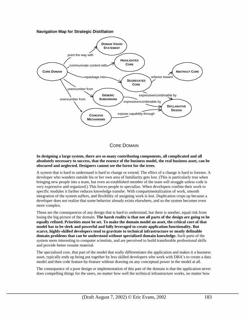
(Draft August 7, 2002) © Eric Evans, 2002 183
Navigation Map for Strategic Distillation
CORE DOMAIN
communciate content with
point the way with
refactor towardrepackage into
unencumber from
unencumber fromexpressive/combinable by
DOMAIN VISION
STATEMENT
HIGHLIGHTED
CORE
SEGREGATED
CORE
GENERIC
SUBDOMAINS
COHESIVE
MECHANISMS
ABSTRACT CORE
DECLARATIVE
DESIGNexpose capability through
expressive/combinable by
CORE DOMAIN In designing a large system, there are so many contr ibuting components, all complicated and all absolutely necessary to success, that the essence of the business model, the real business asset, can be obscured and neglected. Designers cannot see the forest for the trees.
A system that is hard to understand is hard to change or extend. The effect of a change is hard to foresee. A developer who wanders outside his or her own area of familiarity gets lost. (This is particularly true when bringing new people into a team, but even an established member of the team will struggle unless code is very expressive and organized.) This forces people to specialize. When developers confine their work to specific modules it further reduces knowledge transfer. With compartmentalization of work, smooth integration of the system suffers, and flexibility of assigning work is lost. Duplication crops up because a developer does not realize that some behavior already exists elsewhere, and so the system becomes even more complex.
Those are the consequences of any design that is hard to understand, but there is another, equal risk from losing the big picture of the domain. The harsh reality is that not all parts of the design are going to be equally refined. Prior ities must be set. To make the domain model an asset, the cr itical core of that model has to be sleek and power ful and fully leveraged to create application functionality. But scarce, highly-skilled developers tend to gravitate to technical infrastructure or neatly definable domain problems that can be understood without specialized domain knowledge. Such parts of the system seem interesting to computer scientists, and are perceived to build transferable professional skills and provide better resume material.
The specialized core, that part of the model that really differentiates the application and makes it a business asset, typically ends up being put together by less skilled developers who work with DBA’s to create a data model and then code feature-by-feature without drawing on any conceptual power in the model at all.
The consequence of a poor design or implementation of this part of the domain is that the application never does compelling things for the users, no matter how well the technical infrastructure works, no matter how

(Draft August 7, 2002) © Eric Evans, 2002 184
nice the supporting features are. This problem is insidious without a sharp picture of the overall design and the relative significance of the various parts.
One of the most successful projects I’ve joined initially suffered from this syndrome. The goal was to develop a very complex syndicated loan system. Most of the strong talent was happily working on database mapping layers and messaging interfaces while the business model was in the hands of developers new to object technology.
The single exception, an experienced object developer working on a domain problem, devised a way of attaching comments to any of the long-lived domain objects. These comments could be organized in various ways so that traders could see the rationale they or others recorded for some past decision. He also built an elegant user interface that gave intuitive access to the flexible features of the comment model.
These features were useful and well designed. They went into production.
Unfortunately, they were peripheral. This talented developer had modeled his interesting, generic way of commenting activities, implemented it cleanly, and put it into users hands. Meanwhile an incompetent developer was turning the mission-critical “ loan” module into an incomprehensible tangle that the project very nearly did not recover from.
The planning process must drive resources to the most crucial points in the model and design. To do that, those points must be identified and understood by everyone during planning and development.
Those parts of the model distinctive and central to the purposes of the intended applications make up the
CORE DOMAIN. The CORE DOMAIN is where the most value should be added in your system. The patterns in this chapter make it easier to see and use and change.
Boil the model down. Find the CORE DOMAIN and provide a means of easily distinguishing it from the mass of suppor ting model and code. Br ing the most valuable and specialized concepts into sharp relief. Make the CORE small.
Apply top talent to the CORE DOMAIN, and recruit accordingly. Spend the effort to give the CORE a sleek and power ful model and design – sufficient to fulfill the vision of the system. Justify investment in any other par t by how it suppor ts the distilled CORE.
Keep other parts of the model as generic as practical, even using off-the-shelf components when appropriate.
Choosing the CORE
We are looking at those parts of the model particular to representing your business domain and solving your business problems.
The CORE DOMAIN you choose depends on your point of view. For example, many applications need a generic model of money that could represent various currencies and their exchange rates and conversions, but an application to support currency trading might need a more elaborate model of money, and would consider it part of the CORE. Even in such a case, there may be a part of the money model that is very generic. As insight into the domain deepens with experience, the distillation process can continue by separating the generic money concepts and retaining only the specialized aspects of the model in the CORE
DOMAIN.
In a shipping application, the CORE could be the model of how cargoes are consolidated for shipping, how liability is transferred when containers change hands, or how a particular container is routed on various transports to reach its destination. In investment banking, the CORE could include the models of syndication of assets among assignees and participants.
One application’s CORE DOMAIN is another application’s generic supporting component. Still, throughout one project, and usually throughout one company, a consistent CORE can be defined. Like every other part of the design, the identification of the CORE DOMAIN should evolve through iterations. The importance of a particular set of relationships might not have been apparent at first. The objects that seemed obviously central at first may turn out to have supporting roles.

(Draft August 7, 2002) © Eric Evans, 2002 185
The discussion in the following sections, particularly GENERIC SUBDOMAINS, will give more guidelines for these decisions.
Who Does the Work
A corollary to this diversion of the strongest developers away from the core domain is the loss of the opportunity to build and accumulate domain knowledge.
With few exceptions, the most technically proficient members of projects seldom have much knowledge of the domain, which limits their usefulness and reinforces the tendency to put them onto supporting components, sustaining a vicious circle in which lack of knowledge keeps them away from the work that would build domain knowledge.
It is essential to break this cycle by assembling a team matching up a set of strong developers who have a long-term commitment and an interest in becoming repositories of domain knowledge with one or more domain experts who know the business deeply. Domain design is interesting, technically challenging work when approached seriously, and developers can be found who see it this way.
It is usually not practical to hire short-term outside design expertise to help in the nuts and bolts of creating the CORE DOMAIN because the team needs to accumulate domain knowledge, and a temporary member is a leak in the bucket. On the other hand, an expert in a teaching/mentoring role can be very valuable by helping the team build its domain design skills and facilitating the use of sophisticated principles that team members probably have not mastered.
For similar reasons, it is unlikely that the CORE DOMAIN can be purchased. Efforts have been made to build industry-specific model frameworks, conspicuous examples being the semiconductor industry consortium Sematech’s CIM framework for semiconductor manufacturing automation, and IBM’s “San Francisco” frameworks for a wide range of businesses. Although this is a very enticing idea, so far the results have not been compelling, except perhaps as PUBLISHED LANGUAGES (p. 170) facilitating data interchange. Domain-Specific Domain Frameworks [FJ2000] gives a thorough overview of the state of the art. As the field advances, more workable frameworks may be available.
Even so, there is a more fundamental reason for caution: The greatest value of custom software comes from the total control of the CORE DOMAIN. A well-designed framework may be able to provide high-level abstractions that you can specialize for your use. It may save you from developing the more generic parts and leave you free to concentrate on the CORE. If it constrains you more than that, then there are three likely possibilities.
1. You are losing an essential software asset. Back off restrictive frameworks in your CORE DOMAIN.
2. The area treated by the framework is not as pivotal as you thought. Redraw the boundaries of the CORE DOMAIN to the truly distinctive part of the model.
3. You don’ t have special needs in your CORE DOMAIN. Consider a lower risk solution, purchasing software to integrate with your applications.
One way or another, creating distinctive software comes back to a stable team accumulating specialized knowledge and crunching it into a rich model. No shortcuts. No magic bullets.
♦ ♦ ♦
Distilling the CORE DOMAIN is not easy, but it leads to some easy decisions. You’ ll put a lot of effort into making your CORE distinctive, while keeping the rest as generic as possible. If you need to keep some aspect of your design secret as a competitive advantage, it is the CORE DOMAIN. There is no need to waste effort concealing the rest. And whenever a choice has to be made (due to time limitations) between two desirable refactorings, the one that most affects the CORE DOMAIN is chosen first.
The rest of the patterns in this chapter provide techniques for arriving at that easily understood, powerful CORE DOMAIN. Circumstances will dictate the combination of techniques used.
(Draft August 7, 2002) © Eric Evans, 2002 186
A simple DOMAIN VISION STATEMENT communicates the basic concepts and their value with a minimum investment. The HIGHLIGHTED CORE can improve communication and help guide decision making, and still requires little or no modification to the design.
More aggressive refactoring and repackaging can explicitly separate GENERIC SUBDOMAINS, which can then be dealt with separately. Deep modeling leads to encapsulating COHESIVE MECHANISMS with a versatile, communicative DECLARATIVE DESIGN. Removing these distractions disentangles the CORE. Repackaging a SEGREGATED CORE provides the easiest visibility of the CORE and facilitates a cleaner and more powerful core model. Most ambitious is the ABSTRACT CORE that expresses the most fundamental concepts and relationships in a pure form (and requires extensive reorganizing and refactoring of the model).
Each of these techniques requires a successively greater commitment, but a knife gets sharper as its blade is ground finer. Successive distillation of a domain model produces an asset that gives the project speed, agility and precision of execution.
To start, we can boil off the least distinctive aspects of the model. GENERIC SUBDOMAINS provide a contrast to the CORE DOMAIN that clarifies the meaning of each…
GENERIC SUBDOMAINS
Some parts of the model add complexity without captur ing or communicating specialized knowledge. Anything extraneous makes the CORE DOM AIN harder to discern and understand. The model clogs up with details of general pr inciples everyone knows or that belong to specialties that are not your pr imary focus but play a supporting role. Yet, however gener ic, these other elements are essential to the functioning of the system and the full expression of the model.
There is a part of your model that you would like to take for granted. It is undeniably of the domain model, but it abstracts concepts that would probably be needed for a great many businesses. For example, a corporate organization chart is needed in some form by businesses as diverse as shipping, banking, or manufacturing. For another example, many applications track receivables, expense ledgers, and other matters that could all be handled using a generic accounting model.
Often a great deal of effort is spent on peripheral issues in the domain. I personally have witnessed two separate projects that have employed their best developers for weeks in redesigning dates and times with time zones. While such components must work, they are not the conceptual core of the system.
Even if some such generic model element is deemed critical, the overall domain model needs to make prominent the most value-adding and special aspects of your system and be structured to give that part as much power as possible. And this is hard to do when it is mixed with all the interrelated factors.
Therefore,
Identify cohesive subdomains that are not the motivation for your project. Factor them into general models of the GENERIC SUBDOMAINS that have no trace of your specialties, and place them in separate packages. Consider off-the-shelf solutions or published models for these subdomains.
Once they have been separated, give their continuing development lower pr ior ity than the CORE
DOMAIN, and avoid assigning your core developers to the tasks (since they will gain little domain knowledge).
You may have a few extra options when developing these packages.
1. Off-the-shelf solution. Sometimes you can buy an implementation, or use open source code.
+ less code to develop
+ maintenance burden externalized
(Draft August 7, 2002) © Eric Evans, 2002 187
+ code is probably more mature, used in multiple places, and therefore more bullet-proof and complete than home-grown code
- you still have to spend the time to evaluate it and understand it before using it
- quality control being what it is in our industry, you can’ t count on it being correct and stable
- may be over-engineered for your purposes, integration could be more work than a minimalist home-grown implementation
- foreign elements don’ t usually integrate smoothly. May be a distinct UNIFICATION
CONTEXT. Even if not, may be difficult to smoothly reference entities from your other packages.
- may introduce platform dependencies, compiler version dependencies, etc.
Off-the-shelf subdomain solutions usually are not worth the trouble, but are worth investigating. I’ve seen success stories in applications with very elaborate workflow requirements that used commercially available external workflow systems with API hooks. I’ve also seen success with an error-logging package that was deeply integrated into the application. Sometimes generic subdomain packages are in the form of frameworks, which implement a very abstract model that can be integrated with and specialized for your application. The more generic the subcomponent, and the more distilled its own conceptual model, the better the chance that it will be useful.
2. Published design or published conceptual model
+ more mature than a homegrown model, and reflects many people’s insights
+ Instant, high-quality documentation
- may not quite fit your needs or may be over engineered for your needs
Tom Lehrer (a comedic song-writer from the 1950s) said the secret to success in mathematics was, “Plagiarize! Plagiarize. Let no one’s work evade your eyes. […] Only be sure always to call it please, "research".” Good advice in domain modeling, and especially when attacking a GENERIC SUBDOMAIN.
This works best when there is a widely distributed model such as the ones in Analysis Patterns [Fowler1996].
When the field already has a highly formalized and rigorous model, use it. Accounting and physics are two examples that come to mind. Not only are these very robust and streamlined, but they are widely understood by people everywhere, reducing your present and future training burden.
Don’ t feel compelled to implement all aspects of a published model, if you can identify a simplified subset that is self-consistent and satisfies your needs. But in cases where there is a well traveled and documented, or, better yet, formalized model available, it makes no sense to reinvent the wheel.
3. Outsource implementation
+ keeps core team free to work on core domain, where most knowledge is needed and accumulated
+ allows more development to be done without permanently growing team, but without dissipating knowledge of the CORE DOMAIN

(Draft August 7, 2002) © Eric Evans, 2002 188
+ forces an interface-oriented design, and helps keep the subdomain generic, since the specification is being passed outside
- still requires time from core team, since interface, coding standards, and any other important aspects need to be communicated
- significant overhead of transferring ownership back inside, since code has to be understood (still, overhead is less than for specialized parts, since generic conceptual model is presumably easily understood)
+/- code quality can vary. This could be good or bad, depending on the relative caliber of the two teams
Automated tests can play an important role in outsourcing. The implementers should be required to provide unit tests for the code they deliver. A really powerful approach, that helps ensure a degree of quality, clarifies the spec, and smoothes reintegration, is to specify or even write automated acceptance tests for the outsourced components. Note that “outsourced implementation” can be an excellent combination with “published design or conceptual model” .
4. In-house implementation
+ easy integration
+ you get just what you want and no extra
+ Temporary contractors can be assigned
- ongoing maintenance burden and training burden
- it is easy to underestimate the time and cost of developing such packages
Of course, this too combines well with “published design or conceptual model”
GENERIC SUBDOMAINS are the place to try to apply outside design expertise, since they do not require deep understanding of your specialized CORE DOMAIN, and do not present a major opportunity to learn that domain. Confidentiality is less of a concern, since little proprietary information or business practice will be involved in these modules. A GENERIC SUBDOMAIN lessens the training burden for those not committed to deep knowledge of the domain.
Over time, I believe our ideas of what constitutes the CORE model will narrow, and more and more generic models will be available as implemented frameworks, or at least as published analysis models as in [Fowler96]. For now, we still have to develop most of these ourselves, but there is great value in partitioning them from the CORE MODEL.
A Tale of Two Time Zones Twice I’ve watched as the best developers on a project spent weeks of their time solving the problem of storing and converting times with time zones. While I’m always suspicious of such activities, sometimes it is necessary, and these two projects provide almost perfect contrast.
The first was an effort to design cargo shipping scheduling software. To schedule international transports, it is critical to have accurate time calculations, and since all such schedules are tracked in local time, it is impossible to coordinate transports without conversions.
Having clearly established their need for this functionality, they proceeded with development of the CORE DOMAIN and some early iterations of the application using the available time classes and some dummy data. As the application began to mature, it was clear that the existing time classes were not adequate, and that the problem was very

(Draft August 7, 2002) © Eric Evans, 2002 189
intricate because of the variations between the many countries and the complexity of the International Date Line. With their requirements by now even clearer, they searched for an off-the-shelf solution, but found none. They had no option but to build it themselves.
The task would require research, and precision engineering, so they assigned one of their best programmers. But the task did not require any special knowledge of shipping and would not cultivate that knowledge, so they chose a programmer who was on the project on a temporary contract.
This programmer did not start from scratch. He researched several existing implementations of time zones, most of which did not meet requirements, and decided to adapt the public domain solution from BSD Unix, which had an elaborate database and an implementation in C. He reverse engineered the logic and wrote an import routine for the database.
The problem turned out to be even harder than expected (involving, for example, the import of databases of special cases), but the code got written and integrated with the CORE and the product was delivered.
Things went very differently on the other project. An insurance company was developing a new claims processing system, and planned to capture times of various events (when did the car crash, etc.) This would be recorded in local time, ergo time zone functionality was needed.
When I arrived, they had assigned a junior, but very smart, developer to the task, although the exact requirements of the app were still in play and not even an initial iteration had been attempted. He had dutifully set out to build a time zone model a priori.
Not knowing what would be needed, it was assumed that it should be flexible enough to handle anything. The programmer assigned to the task needed help with such a difficult task, so a senior developer was assigned to the task also. Complex code was written, but, since no specific application was using it, it was never clear that it worked correctly.
The project ran aground for various reasons, and the time zone code was never used, but if it had been, my assessment was that initially storing local times tagged with the time zone might have been sufficient, even with no conversion, because this was primarily reference data and not the basis of computations. Even if conversion had turned out to be necessary, all the data was going to be gathered from North America, where time zone conversions are relatively simple.
The main cost of this attention to the time zones was the neglect of the CORE DOMAIN model. If the same energy had been placed there, they might have produced a functioning prototype of their own app and a first cut at a working domain model. Furthermore, the developers involved, who were committed long-term to the project, should have been steeped in the insurance domain, building up critical knowledge within the team.
One thing both projects did right was to cleanly segregate the time zone model from the CORE DOMAIN. A shipping-specific or insurance-specific model of time zones would have coupled the model to this generic supporting model, making the CORE harder to understand (because it would contain irrelevant detail about time zones) and the time zone harder to maintain (because the maintainer would have to understand the CORE and its interrelationship with time zone).
Shipping Transport Scheduler Insurance Claims Tracker
+ generic model decoupled from core
+ core model mature, so resources could
+ generic model decoupled from core
- core model undeveloped, so attention to
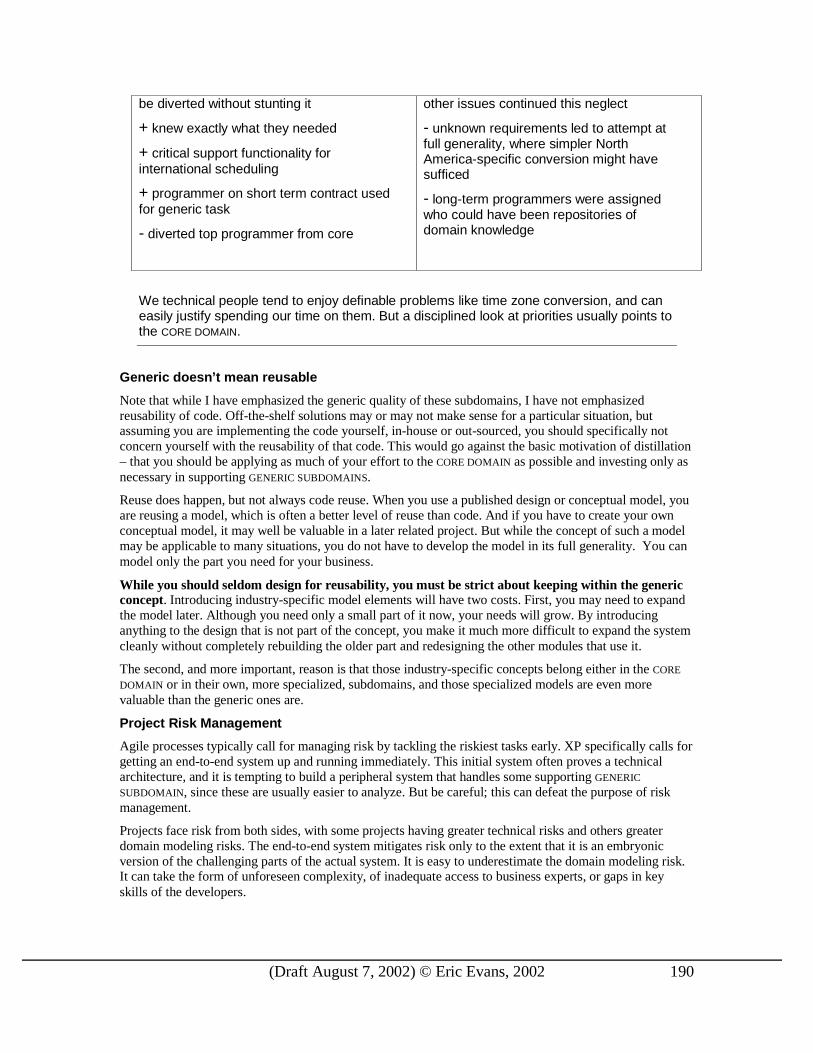
(Draft August 7, 2002) © Eric Evans, 2002 190
be diverted without stunting it
+ knew exactly what they needed
+ critical support functionality for international scheduling
+ programmer on short term contract used for generic task
- diverted top programmer from core
other issues continued this neglect
- unknown requirements led to attempt at full generality, where simpler North America-specific conversion might have sufficed
- long-term programmers were assigned who could have been repositories of domain knowledge
We technical people tend to enjoy definable problems like time zone conversion, and can easily justify spending our time on them. But a disciplined look at priorities usually points to the CORE DOMAIN.
Generic doesn’t mean reusable
Note that while I have emphasized the generic quality of these subdomains, I have not emphasized reusability of code. Off-the-shelf solutions may or may not make sense for a particular situation, but assuming you are implementing the code yourself, in-house or out-sourced, you should specifically not concern yourself with the reusability of that code. This would go against the basic motivation of distillation – that you should be applying as much of your effort to the CORE DOMAIN as possible and investing only as necessary in supporting GENERIC SUBDOMAINS.
Reuse does happen, but not always code reuse. When you use a published design or conceptual model, you are reusing a model, which is often a better level of reuse than code. And if you have to create your own conceptual model, it may well be valuable in a later related project. But while the concept of such a model may be applicable to many situations, you do not have to develop the model in its full generality. You can model only the part you need for your business.
While you should seldom design for reusability, you must be str ict about keeping within the generic concept. Introducing industry-specific model elements will have two costs. First, you may need to expand the model later. Although you need only a small part of it now, your needs will grow. By introducing anything to the design that is not part of the concept, you make it much more difficult to expand the system cleanly without completely rebuilding the older part and redesigning the other modules that use it.
The second, and more important, reason is that those industry-specific concepts belong either in the CORE
DOMAIN or in their own, more specialized, subdomains, and those specialized models are even more valuable than the generic ones are.
Project Risk Management
Agile processes typically call for managing risk by tackling the riskiest tasks early. XP specifically calls for getting an end-to-end system up and running immediately. This initial system often proves a technical architecture, and it is tempting to build a peripheral system that handles some supporting GENERIC
SUBDOMAIN, since these are usually easier to analyze. But be careful; this can defeat the purpose of risk management.
Projects face risk from both sides, with some projects having greater technical risks and others greater domain modeling risks. The end-to-end system mitigates risk only to the extent that it is an embryonic version of the challenging parts of the actual system. It is easy to underestimate the domain modeling risk. It can take the form of unforeseen complexity, of inadequate access to business experts, or gaps in key skills of the developers.

(Draft August 7, 2002) © Eric Evans, 2002 191
Therefore, except when the team has proven skills and the domain is very familiar, the first-cut system should be based on some part of the CORE DOMAIN, however simple.
The same principle applies to any process that tries to push high-risk tasks forward: the CORE DOMAIN is high risk because it is often unexpectedly difficult and because without it, the project cannot succeed.
♦ ♦ ♦
Most of the distillation patterns show how to change the model and code to distill the CORE DOMAIN. The next two patterns, DOMAIN VISION STATEMENT and HIGHLIGHTED CORE, show how the use of supplemental documents can, with a very minor investment, improve communication and awareness of the CORE and focus development effort…
DOMAIN VISION STATEMENT At the beginning of a project, the model usually doesn’ t even exist, yet the need to focus its development is already there. In later stages of development there is a need for an explanation of the value of the system that does not require an in-depth study of the model. Also, the cr itical aspects of the domain model may span multiple UNIFICATION CONTEXTS, but, by definition, these distinct models can’ t be structured to show their common focus.
Many projects write “vision statements” for management. The best of these documents lay out the specific value the application will bring to the organization. Some of these describe the creation of the domain model as a strategic asset. Usually the vision statement document is abandoned after the project gets funding, and is never used in the actual development process or even read by the technical staff.
These documents, or closely related ones that emphasize the nature of the domain model, can be used directly by the management and technical staff during all phases of development to guide resource allocation, to guide modeling choices, and to educate team members. If the domain model serves many masters, you can use this document to show how their interests are balanced.
Write a shor t (~1 page) descr iption of the CORE DOMAIN and the value it will br ing, the “ value proposition” . Ignore those aspects that do not distinguish this domain model from others. Show how the domain model serves and balances diverse interests. Keep it narrow. Write this statement ear ly and revise it as you gain new insight.
This is part of a DOMAIN VISION STATEMENT
This, though important, is not part of a DOMAIN VISION STATEMENT
Airline booking system.
The model can represent passenger priorities and airline booking strategies and balance these based on flexible policies. The model of a passenger should reflect the “relationship” the airline is striving to develop with repeat customers. Therefore, it should represent the history of the passenger in useful condensed form, participation in special programs, affiliation with strategic corporate clients, etc.
Different roles of different users (e.g. passenger, agent, manager) are represented to enrich the model of
The UI should be streamlined for expert users but accessible for first time users.
Access will be offered over the web, by data transfer to other systems, and maybe through other UI’s, so interface will be designed around XML I.O. with transformation layers to serve web pages or translate to other systems.
A colorful animated version of the logo needs to be cached on the client machine so that it can come up quickly on future visits.
When customer submits a

(Draft August 7, 2002) © Eric Evans, 2002 192
represented to enrich the model of relationships and to feed necessary information to the security framework.
Model should support efficient route/seat search and integration with other established flight booking systems.
reservation, make visual confirmation within 5 seconds.
A security framework will authenticate a user’s identity and then limit access to specific features based on privileges assigned to defined user roles.
This is part of a DOMAIN VISION STATEMENT
This, though important, is not part of a DOMAIN VISION STATEMENT
Semiconductor factory automation
The domain model will represent the status of materials and equipment within a wafer fab in such a way that necessary audit trails can be provided and automated product routing can be supported.
The model will not include the human resources required in the process, but must allow selective process automation through recipe download.
The representation of the state of the factory should be comprehensible to human managers, to give them deeper insight and support better decision making.
The software should be web enabled through a servlet, but structured to allow alternative interfaces.
Industry standard technologies should be used whenever possible to avoid in-house development and maintenance costs and to maximize access to outside expertise. Open source solutions are preferred (e.g. Apache web server.)
The web server will run on a dedicated server. The application will run on a single dedicated server.
The DOMAIN VISION STATEMENT can be used as a guide post that keeps the development team headed in a common direction in the ongoing process of distilling the model and code itself. It can be shared with non-technical team members, management, and even customers (except where it contains proprietary information, of course).
♦ ♦ ♦
A DOMAIN VISION STATEMENT sets a guidepost for to give the team a shared direction. Some bridge between the high-level statement and the full detail of the code or model will usually be needed…
HIGHLIGHTED CORE
A DOMAIN VISION STATEMENT identifies the core model in broad terms, but leaves the identification of the specific core elements up to the vagaries of individual interpretation. Unless there is exceptionally high communication on the team, the VISION STATEMENT alone will have little impact. In order to translate the high-level view into a concrete view requires each developer to continually mentally filter the large model to identify the CORE DOMAIN. This constant sifting takes up a lot of concentration, and requires a complete knowledge of the model. Even then, there is no guarantee that two people will choose the same elements, or that the same person will be consistent from day to day. The CORE DOMAIN must be made easier to see.
Structural changes in the organization of the model, such as partitioning GENERIC SUBDOMAINS and a few more to come later in this chapter, can allow the MODULES to tell the story. But it is usually too ambitious to shoot straight for that as the only means of communicating the CORE DOMAIN. To reiterate, the diagram is

(Draft August 7, 2002) © Eric Evans, 2002 193
not the model, nor is the code. The model is a set of concepts that are held in team members heads and expressed through diagrams, code, and other documents. The problem of marking off a privileged part of that model, along with the implementation that embodies it, is a reflection on the model, not necessarily part of the model itself.
A lighter solution can supplement these more aggressive techniques. You may be starting out with existing code that does not differentiate the core well. You may be able to refactor toward these other patterns, but you really need to see the CORE, and share that view, to do that effectively. You may have design constraints that prevent you from making physical separations. Even at an advanced stage, a few carefully selected diagrams or documents may provide mental anchor points and entry points for the team. This problem arises equally for projects that use elaborate UML models and those (like XP projects) that keep few external documents and use the code as the primary repository of the model. An Extreme Programming team might be more minimalist, keep these supplements more casual and more transient (e.g. a hand drawn diagram on the wall for all to see), but these techniques can fold nicely into the process.
Even though we may know broadly what constitutes an element of the CORE DOMAIN, we won’ t come up with consistent choices from developer to developer or even from one day to the next. As we unravel the model for ourselves, we have no effective way of sharing our discover ies, or even of recording them for ourselves to aide memory. The labor of constantly sifting the model in our heads to identify the key parts is simply too hard. Significant structural changes to the code are the ideal way of identifying the core domain, but not always practical in the short-term. In fact, such major code changes are difficult to under take without the very view we are lacking.
Any technique that makes it easy for everyone to know the core domain will do to solve this problem. Two specific techniques can represent this class of solutions.
Distillation Document
Often I create a separate document to describe and explain the CORE DOMAIN. It can be as simple as a list of the most essential conceptual objects. It can be a set of diagrams focused on those objects, showing their most critical relationships. It can walk through the fundamental interactions at an abstract level or by example. It can use UML class or sequence diagrams, nonstandard diagrams particular to the domain, carefully worded textual explanations, or combinations of these. A distillation document is not a complete design document. It is a minimalist entry point that points out the CORE and suggests reasons for closer scrutiny particular pieces. The reader is then guided to the appropriate point in the code, and is provided with a broad view of how the pieces fit, but still goes to the code to see details.
Write a very shor t (3-7 sparse pages) document that descr ibes the CORE DOMAIN and the pr imary interactions among CORE elements.
All the usual risks of separate documents apply: 1. It may not be maintained 2. It may not be read 3. By multiplying the information sources, it may defeat the whole purpose of cutting through
complexity The best way to limit these risks is to be absolutely minimalist about this document. When I write these, they are usually 3-7 sparse pages, including diagrams. By staying away from mundane detail and focusing on the central abstractions and their interactions, the document will age more slowly, since this level of the model is usually more stable.
Write the document to be understood by the non-technical members of the team. Use it as a shared view that delineates what everyone needs to know, and a doorway for all team members to start their exploration of the model and code.
Flagged Core
On my first day on a project at a major insurance company, I was given a copy of the “domain model” , a two hundred page document, purchased at great expense from an industry consortium. I spent a few days wading through a jumble of class diagrams covering everything from the detailed composition of insurance

(Draft August 7, 2002) © Eric Evans, 2002 194
policies to extremely abstract models of relationships between people. The quality of the factoring of these models ranged from high-school project to rather good (a few even described business rules, at least in the accompanying text). But where to start? Two hundred pages.
The project culture heavily favored abstract framework building, and my predecessors had focused on a very abstract model of the relationship of people with each other, with things, activities or agreements. It was actually a nice analysis of these relationships, and their experiments with the model had the quality of an academic research project. But it wasn’ t getting us anywhere near an insurance application.
My first instinct was to start slashing, finding a small CORE DOMAIN to fall back on, then refactoring that and reintroducing other complexities as we went. But the management was alarmed by this attitude. The document was invested with great authority. Its production had involved experts from across the industry, and in any event they had paid the consortium far more than they were paying me, so they were unlikely to weigh my recommendations for radical change too heavily. But I knew we had to get a shared picture of our CORE DOMAIN and get everyone’s efforts focused on that.
Instead of refactoring, I went through the document and, with the help of a business analyst who knew a great deal about the insurance business in general and the requirements of the application we were to build in particular, I identified the handful of sections that presented the essential, differentiating, concepts we needed to work with. I provided a navigation of the model that clearly showed the CORE and its relationship to supporting features.
A new prototyping effort started from this perspective, and quickly yielded a simplified application that demonstrated some of the required functionality.
Two pounds of recyclable paper was turned into a business asset by a few page tabs and some yellow highlighter.
This technique is not specific to object diagrams on paper. A team that uses UML diagrams extensively could use a “stereotype” to identify core elements. A team that uses the code as the sole repository of the model might use comments, maybe structured as Java Doc, or might use some tool in their development environment. The particular technique doesn’t matter, as long as a developer can effortlessly see what is in and what is not in the CORE DOMAIN.
Flag the elements of the CORE DOMAIN within the pr imary repository of the model, without par ticular ly trying to elucidate its role. Make it effor tless for a developer to know what is in or out of the CORE.
The CORE DOMAIN is now clearly visible to those working with the model, with a fairly small effort and low maintenance, at least to the extent that the model is factored fine enough to distinguish the contributions of parts.
Distillation Document as Process Tool
Theoretically, on an XP project, any pair (two programmers working together) can change any code in the system. In practice, some changes have major implications, and call for more consultation and coordination. When working in the INFRASTRUCTURE LAYER, it may be clear that changing the procedure for storing objects will have a wide-ranging impact, but it may not be so obvious in the DOMAIN LAYER, as typically organized.
With the concept of the CORE DOMAIN, this can be clear. Changes to the CORE DOMAIN should have a big effect. Changes to widely used generic elements may require the update of a lot of code, but still shouldn’ t create the conceptual shift that CORE changes do.
Use the distillation document as a guide. When a programming pair changes code that does not require any update to the distillation document, either because they are working outside the CORE or because they are changing only details, they have the full autonomy that XP suggests.
When they realize that the distillation document requires change to stay in synch with their code, either because they are fundamentally changing the CORE DOMAIN elements or relationships, or because they are

(Draft August 7, 2002) © Eric Evans, 2002 195
changing the boundaries of the CORE, including or excluding something different, then consultation is called for, and dissemination of the new model through a new version of the distillation document.
When a model or code change affects the Distillation Document, it requires consultation with other team members. When the change is made, it requires immediate notification of all team members, and the dissemination of a new version of the Distillation Document. Other changes can be integrated without consultation or notification, and will be encountered by other members in the course of their work.
♦ ♦ ♦
Although the VISION STATEMENT and HIGHLIGHTED CORE inform and guide, they do not actually modify the model or the code itself. Partitioning GENERIC SUBDOMAINS physically removes some distracting elements. Next we’ ll look at other ways to structurally change the model and the design itself to make the CORE
DOMAIN more visible and manageable.
COHESIVE MECHANISMS Encapsulating mechanisms is a standard principle of object-oriented design. By hiding complex algorithms in methods with intention revealing names separates the “what” from the “how” . This technique makes a design simpler to understand and use. Yet it has natural limits.
The computations sometimes reach a level of complexity that begins to bloat the design. The conceptual “ what” is swamped by the mechanistic “ how” . A large number of methods that provide algor ithms for resolving the problem obscure the methods that express the problem.
This proliferation of procedures is usually a symptom of a problem in the conceptual model. Refactoring toward deeper insight can yield a model and design whose elements are better suited to solving. The first solution to seek is a model that makes the computation mechanism simple. But now and then the insight emerges that some part of the mechanism is itself conceptually coherent. This conceptual computation will probably not include all of the messy computations you need. But extracting it should make the remaining mechanism easier to understand. We are not talking about some kind of catch-all “calculator” .
Par tition a conceptually cohesive mechanism into a separate lightweight framework. Par ticular ly watch for formalisms or well-documented categories of algor ithms. Expose the capabilities of the framework with an intention-revealing inter face, ideally a DECLARATIVE DESIGN. Now the domain model can be focused on expressing the problem (“ what” ), delegating the intr icacies of the solution (“ how” ) to the framework.
These separated mechanisms are then placed in their supporting roles, leaving a smaller, more expressive CORE DOMAIN that uses the mechanism through a DECLARATIVE interface.
Recognizing a formalism moves some of the complexity of the design into a studied set of concepts. We can implement a solution with confidence and little trial-and-error. We can count on other developers knowing about it or at least being able to look it up. This is similar to the benefits of a published GENERIC
SUBDOMAIN model, but may happen more often because this level of computer science has been more studied. Still, more often than not you will have to create something new. Make it narrowly focused on the computation and avoid mixing in the expressive domain model. There is a separation of responsibilities. The expressive model, part of the CORE DOMAIN or a GENERIC SUBDOMAIN, formulates a fact, rule, or problem. The COHESIVE MECHANISM resolving the rule or completes the computation as specified by the expressive model.
A Mechanism in an Organization Chart I went through this process on a project that needed a fairly elaborate model of an organization chart. This model represented that one person worked for another, and in which branches of the organization, and provided an interface by which relevant questions may be asked and answered. But in a DECLARATIVE DESIGN the means by which the answers are obtained were not a primary concern. Since most of these questions were
(Draft August 7, 2002) © Eric Evans, 2002 196
along the lines of “Who, in this chain of command, has authority to approve this?” or “Who, in this department, is capable of handling an issue like this?” the team realized that most of the complexity involved traversing specific branches of the organizational tree searching for specific people or relationships. This is exactly the kind of problem solved by the well developed formalism of a “graph”, a set of nodes connected by arcs (called “edges”) and the rules and algorithms needed to traverse the graph.
We implemented a graph traversal framework as a GENERIC SUBDOMAIN. This framework used standard graph terminology and algorithms familiar to most computer scientists and abundantly documented in textbooks. By no means did we implement a fully general graph. It was a small subset of that conceptual framework that covered the features needed for our organization model.
Now the organization model could simply state, using standard graph terminology, that each person is a node, and that each relationship between people is an edge (arc) connecting those nodes. After that, presumably, mechanisms within the graph framework could find the relationship between any two people.
If this mechanism had been incorporated into the domain model, it would have cost us in two ways. The model would have been coupled to a particular method of solving the problem, limiting future options. More importantly, the model of organization would have been greatly complicated and muddied. Keeping mechanism and model separate allowed a DECLARATIVE DESIGN of organizations that was much clearer. And the intricate code for graph manipulation was isolated in a purely mechanistic framework, based on proven algorithms, that could be maintained and unit tested in isolation.
Another example of a COHESIVE MECHANISM would be a framework for constructing SPECIFICATION objects that can support the basic comparison and combination operations expected of them. The SPECIFICATION pattern lends itself to a DECLARATIVE DESIGN. By providing a framework, the CORE DOMAIN and GENERIC
SUBDOMAINS can declare their specifications in the clear easily understood conceptual language described of that pattern. The intricate operations involved in carrying out the comparisons and combinations can be left to the framework.
GENERIC SUBDOMAIN v. COHESIVE MECHANISM
GENERIC SUBDOMAINS and COHESIVE MECHANISMS are motivated by the same desire to unburden the core domain. The difference is the nature of the responsibility taken on. A GENERIC SUBDOMAIN is based on an expressive model that represents some aspect of how the team views the business domain. In this it is no different than the CORE DOMAIN, just less central, less important, less specialized. The COHESIVE
MECHANISM does not represent the business; it solves some sticky computational problem posed by the expressive modules.
An expressive model proposes; a COHESIVE MECHANISM disposes.
In practice, unless you recognize a formalized, published computation, this distinction is usually not pure, at least at not at first. In successive refactoring it should either be distilled into a purer mechanism, or be transformed into a GENERIC SUBDOMAIN with some previously unrecognized conceptual model that makes the mechanism simple.
When a mechanism is part of the CORE DOMAIN
You almost always want to remove mechanisms from the CORE DOMAIN. The one exception is when a mechanism is itself proprietary and a key part of the value of the software. This is sometimes the case with highly specialized algorithms. For example if one of the distinguishing features of a shipping logistics application was a particularly effective algorithm for working out schedules, that mechanism could be considered part of the conceptual core. I once worked on a project at an investment bank in which highly proprietary algorithms for rating risk were definitely in the CORE DOMAIN. (In fact, they were held so closely that even most of the core developers were not allowed to see them). Of course, these algorithms

(Draft August 7, 2002) © Eric Evans, 2002 197
are probably a particular implementation of a set of rules that really predict risk. Deeper analysis might lead to a deeper model that would allow those rules to be explicit, with an encapsulated solving mechanism.
But that would be another incremental improvement in the design, for another day. The decision as to whether to do go that next step would be based on cost benefit: How difficult would it be to work out that new design? How difficult is the current design to understand and modify? How much easier would it be with a more advanced design, for the type of people who would be expected to do the work?
Full Circle
Organization Chart Reabsorbs Its Mechanism Actually, a year after we completed the organization model, other developers redesigned it to eliminate the separation of the graph framework. Performance problems in the deployment environment were emerging, and they felt the complication of separating the mechanism into a separate package was not warranted. Instead, they added node behavior to the parent class of the organizational ENTITIES. Still, they retained the declarative public interface of the organization model. They even kept the mechanism encapsulated, within the organizational ENTITIES.
These full circles are common, but they do not return to their starting point. The end result is usually a deeper conceptual model that more clearly differentiates facts, goals and mechanisms. Pragmatic refactoring retains the important virtues of the intermediate stages while shedding the unneeded complications.
DECLARATIVE DESIGN One particular design style deserves special mention in this chapter on strategic distillation. The key to distillation is being able to see what you are doing – cutting to the essence without being distracted by irrelevant detail.
Declarative design arises again and again in that context. COHESIVE MECHANISMS are by far most effective when they provide access through a declarative interface. GENERIC SUBDOMAINS with a DECLARATIVE
DESIGN allow the CORE DOMAIN to make meaningful statements rather than calling obscure functions. But an exceptional payoff comes when the CORE DOMAIN itself breaks through to a deep model and starts to function as a language that can express the most important situations the application deals with, flexibly and concisely. One of the most valuable characteristics of many deep models is a DECLARATIVE DESIGN.
When a DECLARATIVE DESIGN reaches maturity, it provides an easily understood set of elements that can be combined unambiguously to accomplish complex tasks or express complex information, just as words are combined into sentences. In fact, the names of the elements of such a design become part of the UBIQUITOUS LANGUAGE of the project.
♦ ♦ ♦
Factoring out GENERIC SUBDOMAINS to reduce clutter and COHESIVE MECHANISMS to serve up complex mechanisms leaves behind a more focused model of your business, with fewer distractions that add no particular value to the way you do your business. But you are unlikely ever to find good homes for everything in the domain model that is not CORE. The SEGREGATED CORE takes a more direct approach to structurally marking off the CORE DOMAIN…

(Draft August 7, 2002) © Eric Evans, 2002 198
SEGREGATED CORE
Elements in the model may par tially serve the core and par tially play suppor ting roles. Core elements may be tightly coupled to generic ones. The conceptual cohesion of the core may not be strong or visible. All this clutter and entanglement chokes the core. Designers can’ t clear ly see the most impor tant relationships, leading to a weak design.
By factoring out GENERIC SUBDOMAINS, you clear away some of the obscuring detail from the domain, making the core more visible. But it is hard work identifying and clarifying all these subdomains, and some of them don’t seem worth the trouble. Meanwhile, the all important core domain is left entangled with the residue.
Refactor the model to separate the core concepts from supporting players (including ill-defined ones) and strengthen the cohesion of the core while reducing its coupling to other code. Factor all generic or suppor ting elements into other objects and place them into other packages, even if this means refactor ing the model in ways that separate highly coupled elements.
This is basically taking the same principles we applied to GENERIC SUBDOMAINS but from the other direction. The cohesive subdomains that are central to our application can be identified and partitioned into coherent packages of their own. What is done with the undifferentiated mass left behind is important – but not as important. It can be left more or less where it was, or placed into packages based on prominent classes. Eventually, more and more of the residue can be factored into GENERIC SUBDOMAINS, but in the short term any easy solution will do, just so the focus on the SEGREGATED CORE is retained.
The steps to refactor to SEGREGATED CORE typically are something like this:
1. Identify a core subdomain (possibly drawing from the Distillation Document).
2. Move related classes to a new package, named for the concept that relates them.
3. Refactor code to sever data and functionality that are not directly expressions of the concept. Put the removed aspects into (possibly new) classes in other packages. Try to place them with conceptually related tasks, but don’ t waste too much time being perfect. Keep focused on scrubbing the core subdomain and making the references from it to other packages explicit and self-explanatory.
4. Refactor the remaining core to make its relationships and interactions simpler and more communicative, and to minimize and clarify its relationships with other packages. (This becomes an ongoing refactoring objective.)
Costs of Creating a SEGREGATED CORE
Segregating the core will sometimes make relationships with tightly coupled non-core classes more obscure or even more complicated, but the benefit of clarifying the core domain and making it much easier to work on outweighs this.

(Draft August 7, 2002) © Eric Evans, 2002 199
The SEGREGATED CORE will let you enhance the cohesion of that CORE DOMAIN. Since there are many meaningful ways of breaking down a model, sometimes in the creation of a SEGREGATED CORE a nicely cohesive package may be broken, sacrificing that cohesion for the sake of bringing out the cohesiveness of the CORE DOMAIN. This is a net gain since the greatest value-added of enterprise software comes from the enterprise specific aspects of the model.
And, of course, segregating the core is a lot of work. Although some of that effort also contributes to continuous refactoring on the finer scale, it must be acknowledged that a decision to go to a segregated core will potentially absorb developers in changes all over the system.
The time to use SEGREGATED CORE is when you have a large UNIFICATION CONTEXT that is critical to the system, but where the essential part of the model is being obscured by a great deal of supporting capability.
Evolving Team Decision
As with many strategic design decisions, an entire team must move to a SEGREGATED CORE together. This means a team decision process and a team disciplined and coordinated enough to carry out the decision. The challenge is to constrain everyone to use the same definition of the CORE while not freezing that decision. Because the CORE DOMAIN evolves just like every other aspect of a design. Experience working with a segregated core will lead to new insights into what is essential and what is supporting. Those insights should feed back in the form of a refined definition of the core and refactoring of the code.
This means that new insights must be shared with the team on an ongoing basis, but an individual (or programming pair) cannot act on those insights unilaterally. Whatever the process is for joint decisions, whether consensus or team leader, it must be agile enough to make repeated course corrections. Communication must be effective enough to keep everyone together in one view of the CORE.
Segregating the Core of a Cargo Shipping Model We start with the following model as the basis of software for cargo shipping coordination.
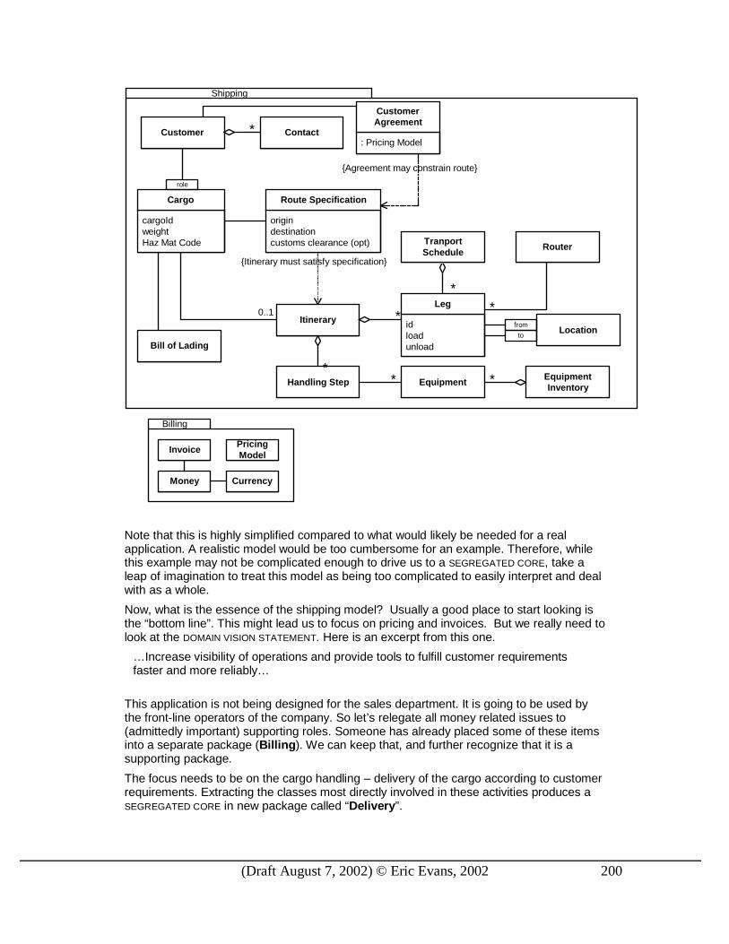
(Draft August 7, 2002) © Eric Evans, 2002 200
Shipping
cargoIdweightHaz Mat Code
Cargo
origindestinationcustoms clearance (opt)
Route Specification
0..1
{Itinerary must satisfy specification}
Router
idloadunload
Leg
Itinerary
*
TranportSchedule
*
Customer: Pricing Model
CustomerAgreement
role
Locationto
from
Handling Step*
EquipmentEquipmentInventory
**
Billing
InvoicePricingModel
Money Currency
*
Bill of Lading
Contact*
{Agreement may constrain route}
Note that this is highly simplified compared to what would likely be needed for a real application. A realistic model would be too cumbersome for an example. Therefore, while this example may not be complicated enough to drive us to a SEGREGATED CORE, take a leap of imagination to treat this model as being too complicated to easily interpret and deal with as a whole.
Now, what is the essence of the shipping model? Usually a good place to start looking is the “bottom line”. This might lead us to focus on pricing and invoices. But we really need to look at the DOMAIN VISION STATEMENT. Here is an excerpt from this one.
…Increase visibility of operations and provide tools to fulfill customer requirements faster and more reliably…
This application is not being designed for the sales department. It is going to be used by the front-line operators of the company. So let’s relegate all money related issues to (admittedly important) supporting roles. Someone has already placed some of these items into a separate package (Billing). We can keep that, and further recognize that it is a supporting package.
The focus needs to be on the cargo handling – delivery of the cargo according to customer requirements. Extracting the classes most directly involved in these activities produces a SEGREGATED CORE in new package called “Delivery”.
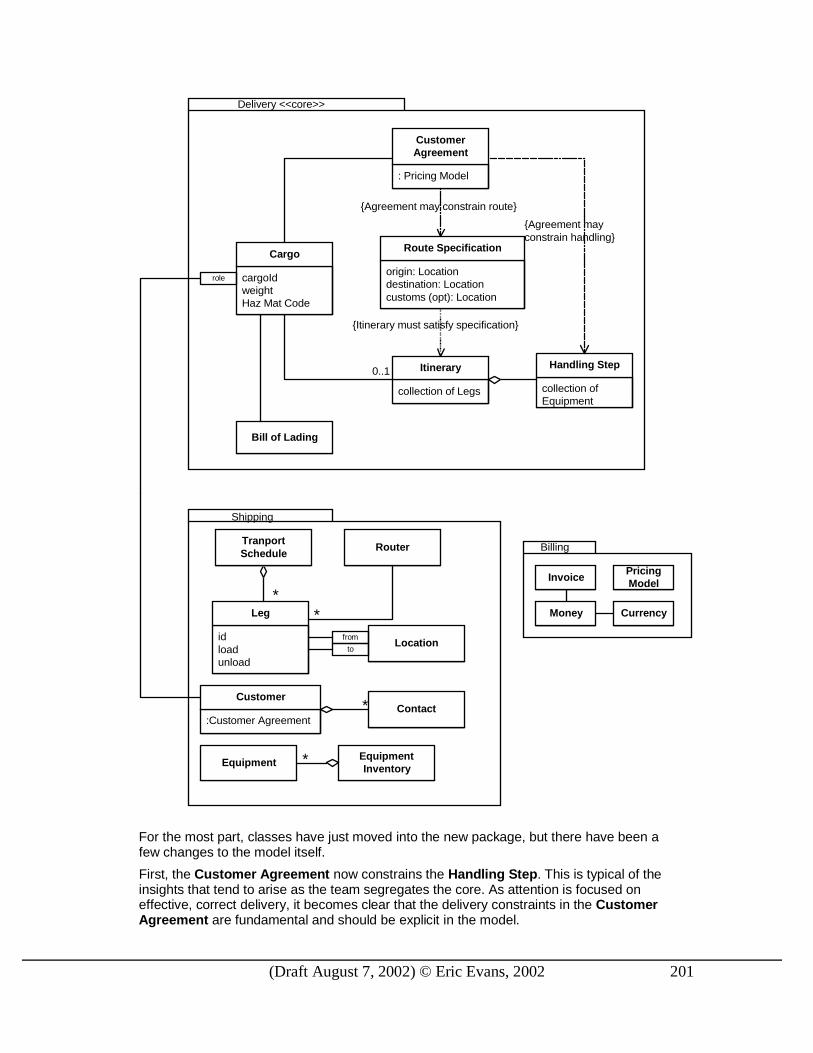
(Draft August 7, 2002) © Eric Evans, 2002 201
Shipping
Delivery <<core>>
Billing
InvoicePricingModel
Money Currency
cargoIdweightHaz Mat Code
Cargo
origin: Locationdestination: Locationcustoms (opt): Location
Route Specification
0..1
{Itinerary must satisfy specification}
Router
collection of Legs
Itinerary
*
TranportSchedule
:Customer Agreement
Customer
: Pricing Model
CustomerAgreement
role
collection ofEquipment
Handling Step
*
EquipmentEquipmentInventory
*
Bill of Lading
{Agreement may constrain route}
{Agreement mayconstrain handling}
idloadunload
Leg
Locationto
from
Contact*
For the most part, classes have just moved into the new package, but there have been a few changes to the model itself.
First, the Customer Agreement now constrains the Handling Step. This is typical of the insights that tend to arise as the team segregates the core. As attention is focused on effective, correct delivery, it becomes clear that the delivery constraints in the Customer Agreement are fundamental and should be explicit in the model.

(Draft August 7, 2002) © Eric Evans, 2002 202
The other change is more pragmatic. In the refactored model, the Customer Agreement is attached directly to the Cargo, rather than requiring a navigation through the Customer. (It will have to be attached when the cargo is booked, just as the Customer is.) At actual delivery time, the customer is not as relevant to operations as the agreement itself, so the most important scenarios are as simple and direct as possible. In the other model, the correct Customer had to be found, according to the role it played in the shipment, and then queried for its Customer Agreement. This interaction would clog up every story you set out to tell about the model. Now it becomes easy to pull the Customer out of the core altogether.
And what about pulling customer out, anyway? Certainly the focus is on fulfilling the customer’s requirements, so at first it seems to belong in the core. Yet the interactions during delivery do not usually need to involve the Customer class now that the Customer Agreement is available directly. And the basic model of a customer is pretty generic.
A strong argument could be made for Leg remaining in the core. I tend to be minimalist in the core, and the Leg has tighter cohesion with Transport Schedule, Router, and Location, none of which needed to be in the core. But if a lot of the stories I wanted to tell about this model involved Legs, I’d move it into the Delivery package and suffer the awkwardness of its separation from those other classes.
In this example, all the class definitions are the same as before, but often distillation requires refactoring the classes themselves to separate the generic and domain specific responsibilities, which can then be segregated.
Now that we have a SEGREGATED CORE, the refactoring is complete. But the Shipping package we are left with is just “everything left-over after we pulled out the core”. We can follow up with other refactorings to get more communicative packaging.

(Draft August 7, 2002) © Eric Evans, 2002 203
Customer Logistics
Delivery <<core>>
Money <<generic>>
:Money
Invoice PricingModel
Money Currency
cargoIdweightHaz Mat Code
Cargo
origin: Locationdestination: Locationcustoms (opt): Location
Route Specification
0..1
{Itinerary must satisfy specification}
Router
collection of Legs
Itinerary
*
TranportSchedule
:Customer Agreement
Customer
: Pricing Model
CustomerAgreement
role
collection ofEquipment
Handling Step
*
EquipmentEquipmentInventory
*
Bill of Lading
{Agreement may constrain route}
{Agreement mayconstrain handling}
idloadunload
Leg
Locationto
from
Contact*
It might take several refactorings to get to this point; it doesn’t have to be done at once. Here, we’ve ended up with one SEGREGATED CORE package, one GENERIC SUBDOMAIN, and two domain specific packages in supporting roles. (Deeper insight might eventually produce a GENERIC SUBDOMAIN for Customer, or it might end up more specialized for shipping.)
Recognizing conceptual packages that communicate and provide convenience (by grouping cohesive, coupled elements) requires understanding and experience with the domain. The business experts can and should be involved in reaching such insights. As

(Draft August 7, 2002) © Eric Evans, 2002 204
the developers work with the model more and more they will come to also have insight. These insights, crunched knowledge, can be captured in the model.
ABSTRACT CORE
Even the CORE DOMAIN model usually has so much detail that communicating the big-picture can be difficult.
We usually deal with this by breaking the large model into narrower subdomains that are small enough to be grasped. This reductive style of packaging often works to make a complicated model manageable. But sometimes creating separate packages can obscure or even complicate the interactions between the subdomains.
When there is a lot of interaction between subdomains in separate packages, either many references will have to be created between packages, which defeats much of the value of the partitioning, or the interaction has to be made more indirect, which makes the model less communicative, harder to understand.
Consider slicing horizontally rather than vertically. Polymorphism gives us the power to ignore a lot of the detailed variation among instances of an abstract type. If most of the interactions across the conventional packages can be expressed at the level of these polymorphic interfaces, it may make sense to refactor these types into a special core package.
We are not looking for a technical trick here. This is only a valuable technique when the polymorphic interfaces correspond to fundamental concepts in the domain. In that case, separating these abstractions accomplishes both the technical advantages of tighter coupling within packages and looser coupling between them and the fundamental objective of a more communicative design.
Therefore,
Identify the most fundamental conceptual elements in the model and factor them into distinct classes, abstract classes, or interfaces. Design this abstract model so that it expresses most of the interaction between significant components. Place this abstract overall model in its own package, while the specialized, detailed implementation classes are placed in their own packages defined by subdomain.
Most of the specialized classes will now reference the core package, but not the other specialized packages. The abstract core gives a very succinct view of the main concepts and their interactions.

(Draft August 7, 2002) © Eric Evans, 2002 205
The process of factoring out the abstract core is not mechanical. For example, if all the classes that were frequently referenced across packages were simply moved into a separate package, the likely result would be a meaningless mess. It requires a deep understanding of the key concepts and roles they play in the major interactions of the system. And it usually requires some redesign. In other words, it is an example of refactoring to deeper insight (p. ##).
The ABSTRACT CORE should end up looking a lot like the Distillation Document (if both were used on the same project, and the Distillation Document had evolved with the application as insight deepened), though, of course, the ABSTRACT CORE will be code, and therefore more rigorous and more complete.
Deep Models Distillation does not operate only on the gross level of separating parts of the domain away from the core. It also means refining those subdomains, especially the core, through continuously refactoring toward deeper insight, driving toward a deep model. The goal is a design that makes the conceptual model obvious, a model that expresses the domain simply and a model and design that facilitate solutions of the relevant problems.
A deep model distills the most essential aspects of a domain in a form that makes it simple to solve the important problems of the application with interactions of the elements.
While the process of refactoring toward deeper insight needs to be applied continuously, and while a breakthrough to a deep model can provide value anywhere, it is in the CORE DOMAIN that it can change the trajectory of a project.
Refactoring and Distillation When you encounter a large system that is poorly factored, where do you start? In the XP community, the answer tends to be either one of these:
1. Just start anywhere, since it all has to be refactored.
2. Wherever it is hurting. I’ ll refactor what I need to in order to get my specific task done.
I don’ t hold with either of these. The first is impractical except in a few projects staffed entirely with top programmers. The second tends to pick around the edges, treating symptoms and ignoring root causes, shying away from the worst tangles. Eventually the code becomes harder and harder to refactor.
So, if you can’ t do it all, and you can’ t be pain-driven, what do you do?
1. In a pain-driven refactoring, you look to see if the root involves the CORE DOMAIN or the relationship of the CORE to a supporting element. If it is, you bite the bullet and fix that first.
2. When you have the luxury of refactoring freely, you focus first on better factoring of the CORE
DOMAIN, on improving the segregation of the CORE, and on purifying supporting subdomains to be generic.
This is how to get the most bang for your refactoring buck.
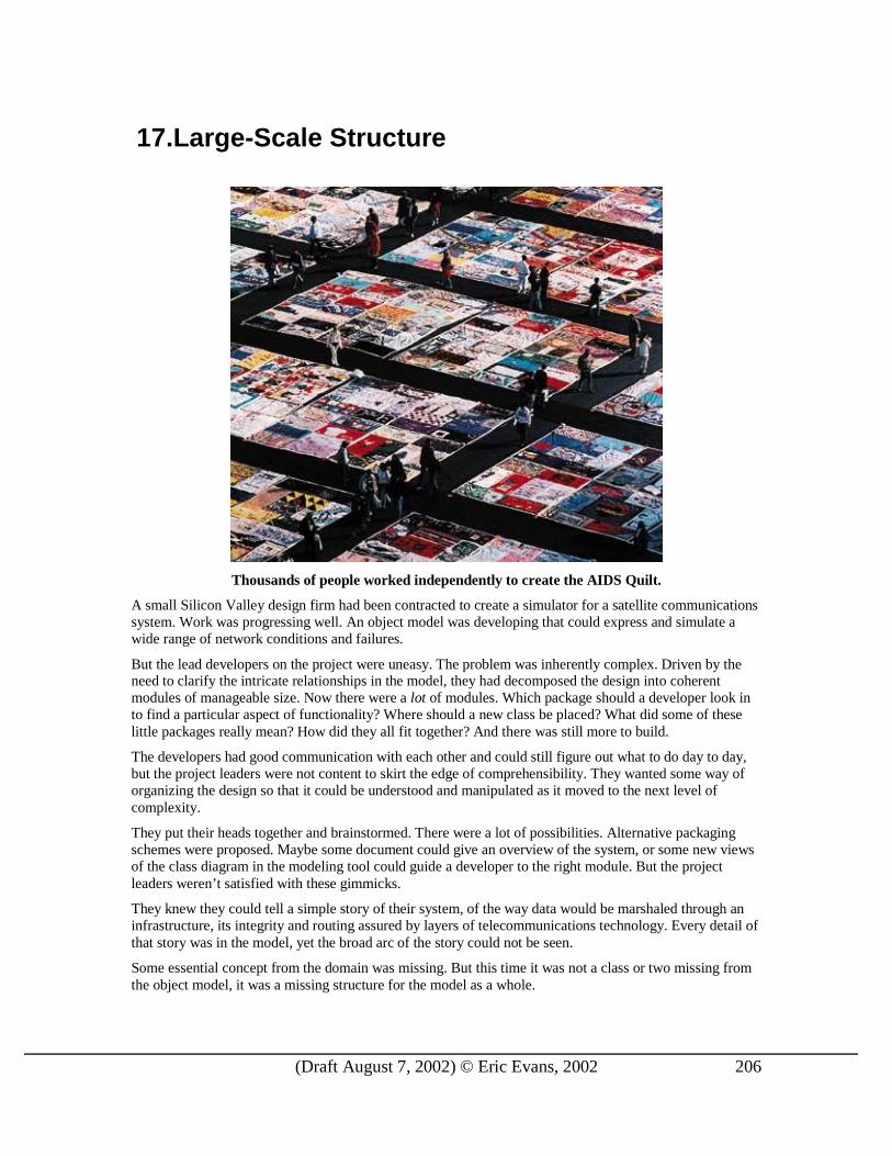
(Draft August 7, 2002) © Eric Evans, 2002 206
17. Large-Scale Structure
Thousands of people worked independently to create the AIDS Quilt.
A small Silicon Valley design firm had been contracted to create a simulator for a satellite communications system. Work was progressing well. An object model was developing that could express and simulate a wide range of network conditions and failures.
But the lead developers on the project were uneasy. The problem was inherently complex. Driven by the need to clarify the intricate relationships in the model, they had decomposed the design into coherent modules of manageable size. Now there were a lot of modules. Which package should a developer look in to find a particular aspect of functionality? Where should a new class be placed? What did some of these little packages really mean? How did they all fit together? And there was still more to build.
The developers had good communication with each other and could still figure out what to do day to day, but the project leaders were not content to skirt the edge of comprehensibility. They wanted some way of organizing the design so that it could be understood and manipulated as it moved to the next level of complexity.
They put their heads together and brainstormed. There were a lot of possibilities. Alternative packaging schemes were proposed. Maybe some document could give an overview of the system, or some new views of the class diagram in the modeling tool could guide a developer to the right module. But the project leaders weren’ t satisfied with these gimmicks.
They knew they could tell a simple story of their system, of the way data would be marshaled through an infrastructure, its integrity and routing assured by layers of telecommunications technology. Every detail of that story was in the model, yet the broad arc of the story could not be seen.
Some essential concept from the domain was missing. But this time it was not a class or two missing from the object model, it was a missing structure for the model as a whole.

(Draft August 7, 2002) © Eric Evans, 2002 207
After mulling over the problem for a week or two, the idea began to gel. They would impose a structure on the design. The entire simulator would be viewed as a series of layers related to aspects of the communications system being simulated. The bottom layer would represent the physical infrastructure, the basic ability to transmit bits from one node to another. Then there would be a packet routing layer that brought together the concerns of how a particular data stream would be directed. Other layers would identify other conceptual levels of the problem. These layers would outline their story of the system.
They set out to refactor the code to conform to the new structure. Modules had to be redefined so as not to span layers. In some cases, object responsibilities were refactored so that each object would clearly belong to one layer. Conversely, throughout this process the definitions of the conceptual layers themselves were refined based on the hands-on experience of applying them. The layers, modules and objects coevolved until, in the end, the entire design followed the contours of this layered structure.
These layers were not modules nor any other artifact in the code. They were an overarching set of rules that constrained the boundaries and relationships of any particular module or object throughout the design, even at interfaces with other systems.
This imposed order brought the design back to comfortable intelligibility. People knew roughly where to look for a particular function. Individuals working independently could make design decisions that were broadly consistent with each other. The complexity ceiling had been lifted.
♦ ♦ ♦
Even with a MODULAR breakdown, a large model can be too complicated to grasp. The MODULES chunk the design into manageable bites, but there may be many of them. Also, this does not necessarily bring uniformity to the design. Object to object, package to package, a jumble of design decisions may be applied, each defensible, but idiosyncratic.
The strict segregation imposed by UNIFICATION CONTEXTS prevents corruption and confusion, but does not, in itself, make it easier to see the system as a whole.
Distillation does help by focusing the attention on the core and presenting the other models in their supporting roles. But it is still necessary to understand the supporting elements and their relationships to the CORE DOMAIN and to each other. And, while the CORE DOMAIN would ideally be so clear and easily understood that no additional guidance would be needed, we are not always at that point.
On a project of any size, people must work somewhat independently on different parts of the system. Without any coordination or rules, a confusion of different styles and distinct solutions to the same problems arise, making it hard to understand how the parts fit together and impossible to see the big picture. Learning about one part of the design will not transfer to other parts, so the project will end up with specialists in different modules who cannot help each other outside their narrow range. CONTINUOUS
INTEGRATION breaks down and the UNIFICATION CONTEXT fragments.
In a large system without any overarching principle that allows elements to be interpreted in terms of their role in patterns that span the whole design, developers cannot see the forest for the trees. We need to be able to understand the role of an individual part in the whole without delving into details of the whole.
A ” large-scale structure” is a language that lets you discuss and understand the system in broad strokes. A set of high-level concepts and/or rules establishes a pattern of design for an entire system. This organizing principle can guide design as well as aid understanding. It helps coordinate independent work because there is a shared concept of the big picture of the role of parts and the shape of the whole.
You can’ t represent most large-scale structures in UML, and you don’ t need to. Most large-scale structures shape and explain the model and design, but do not appear in it. They provide an extra level of communication about the design. In the examples of this chapter you’ ll see many informal UML diagrams on which I’ve superimposed information about the large-scale structure.
Devise a pattern of rules or roles and relationships that will span the entire system and which allows some understanding of a part’s place in the whole even without detailed knowledge of the par t’s responsibility.

(Draft August 7, 2002) © Eric Evans, 2002 208
Structure may be confined to one UNIFICATION CONTEXT but will usually span multiple contexts, providing the conceptual organization to hold them together. A good structure gives insight into the model and complements distillation.
Large-scale structure can save a project, but an ill-fitting structure can severely hinder development. This chapter explores patterns for successfully structuring a design at this level.
Some Patterns of Large-Scale Structure
EVOLVING
ORDER
discover/refine
discover/refine
formalize into
discover/refine
SYSTEM
METAPHORE
RESPONSIBILITY
LAYERS
PLUGGABLE
COMPONENTS
ABSTRACT
DOMAIN
FRAMEWORK
discover/refine
EVOLVING ORDER Many developers have experienced the cost of an unstructured design. To avoid this anarchy, projects impose architectures that constrain development in various ways. Some technical architectures do solve technical problems, such as networking or data persistence, but when architectures start venturing into the arena of the application and domain model they can create problems of their own. They often prevent the developers from creating designs and models that work well for the specifics of the problem. The most ambitious ones can even take away from application developers familiarity and technical power of the programming language itself. And whether technical or domain oriented, architectures freeze a lot of up-front design decisions that can become a straight jacket as requirements change and as understanding deepens.
While some successful technical architectures have evolved over the years, the structure of the DOMAIN
LAYER is less well understood, and needs vary widely from one application to the next. An upfront imposition of a large-scale structure is likely to be costly. As development proceeds, you will almost certainly find a more suitable structure, and you may even find that the prescribed structure is prohibiting you from taking a design route that would greatly clarify or simplify the application. You may be able to use some of the structure, but you’re forgoing opportunities. Your work slows down as you try workarounds or try to negotiate with the architects. But your managers think the architecture is done. It was supposed to make this application easy, so why aren’ t you working on the application instead of all these architecture problems? The managers and architecture teams may even be open to input, but if each change is a heroic battle, it is too exhausting.
Design free-for -alls produce systems no one can make sense of as a whole, that are very difficult to maintain. But architectures can straightjacket a project with up-front design assumptions, and take too much power away from the developers/designers of particular par ts of the application. Soon,

(Draft August 7, 2002) © Eric Evans, 2002 209
developers will dumb down the application to fit the structure, or they will subvert it and have no structure at all, br inging along the problems of uncoordinated development.
The problem is not the existence of guiding rules, but rather the rigidity and source of those rules. If the rules governing the design really fit the circumstances, they will not get in the way but actually push development in a helpful direction, as well as providing consistency.
Therefore,
Let this conceptual large-scale structure evolve with the application, possibly changing to a completely different type of structure along the way. Don’ t over-constrain the detailed design and model decisions that must be made with detailed knowledge.
Individual parts have natural or useful ways of being organized and expressed that may not apply to the whole, so imposing global rules makes these parts less ideal. Choosing to use a large-scale structure favors manageability of the model as a whole over optimal structuring of the individual parts. Therefore, there will be some compromise between powerful structure and freedom to express individual components in the most natural way. This can be mitigated by careful selection of the structure and by avoiding over-constrictive structures. A really nice fit of structure to domain and requirements actually makes detailed modeling and design easier, by helping to quickly eliminate a lot of options.
It can also give shortcuts to design decisions that could, in principle, be found by working on the individual object level, but which would, in practice, take too long and have inconsistent results. Of course, continuous refactoring is still necessary, but this will make it a more manageable process, and can help make different people come up with consistent solutions.
A large-scale structure generally needs to be applicable across UNIFICATION CONTEXTS. Through iteration on a real project, a structure will lose features that tightly bind it to a particular model and evolve features that correspond to deep insights into the domain. This doesn’ t mean that it will have no assumptions about the model, but not about the points that vary within the particular models in use on the project.
Designers may have no control over the model of some parts of the system, especially in the case of external or legacy systems. So large-scale structure must accommodate such constraints on development. This may be done by changing the structure to better fit the specific external elements. It may be done by specifying ways in which the application relates to externals. It may be done by making the structure loose enough to flex around awkward realities.
Unlike UNIFICATION CONTEXT, using a large-scale structure is optional. One should be applied when costs and benefits favor it, and when a fitting structure is found. In fact, it is not needed for systems that are simple enough to be understood when broken into MODULES. Large-scale structure should be applied when a structure can be found that greatly clar ifies the system without forcing an unnatural constraint into model development. Since an ill-fitting structure is worse than none, it is best not to shoot for comprehensiveness, but a minimal set that solves the problems that have emerged. Less is more.
♦ ♦ ♦
As mentioned, it is no mean feat to create a structure that gives the necessary freedom to developers while still averting chaos. Although a lot of work has been done on technical architectural for software systems, little has been published on the structuring of the DOMAIN LAYER. Some approaches that have been tried weaken the object-oriented paradigm, such as those that break down the domain by application task or by use-case. This whole area is still undeveloped. I’ve observed a few general patterns of LARGE-SCALE
STRUCTURES that have emerged on various projects. I’ ll discuss four in this chapter. One of these may fit your needs or lead to ideas for a STRUCTURE tailored to your project.
SYSTEM METAPHOR [BECK 2000] This pattern is part of the lore of the Extreme Programming community. It is harmonious with the object paradigm, and provides a loose, easily understood STRUCTURE that can be applied across UNIFICATION

(Draft August 7, 2002) © Eric Evans, 2002 210
CONTEXTS. Unfortunately, few projects have found really useful metaphors, and people have tried to push it into domains where it is counterproductive. That said, it has is a well-known form of LARGE-SCALE
STRUCTURE that could be useful on some projects, and it nicely illustrates the general concept of a STRUCTURE.
<<pull material from XP book. Give usual example of C3 project.>>
On one level, metaphor runs so deeply in the way we think that it pervades every design. Systems have “ layers” that “ lay on top” of each other. They have “kernels” at their centers. This pattern refers to a conscious quest for a metaphor that conveys the central theme of a design.
A familiar software metaphor that has proven successful is the “ firewall” . Just as a building is saved from a fire raging through neighboring buildings, the local network is protected from the dangers of the larger networks outside the firewall. This metaphor has influenced network architectures and shaped a whole product category. Multiple competing firewalls are available for consumers, developed independently, understood to be somewhat interchangeable. Novices to networking readily grasp the concept. This shared understanding throughout the industry and among customers is in no small part due to the metaphor.
Yet it is an inexact analogy, and its power cuts both ways. The firewall analogy sometimes leads to an insufficiently selective barrier that impedes desirable exchanges, while no protection is offered against threats originating within the wall. Wireless LANs, for example, are vulnerable. Not to say that one piece of software should solve all problems. The clarity of the firewall has been a boon. But all metaphors carry baggage, and should be continuously reexamined for overextension or inaptness.
A design can be organized around a metaphor that need not be related to the domain itself (e.g. a payroll system is like a manufactur ing assembly line). This metaphor enters the ubiquitous language and then both facilitates understanding of the system and guides development of it. This helps increase consistency in different parts of the system, even in different unification contexts.
A powerful metaphor introduces the risk that the design will take on aspects of the analogy that are not desirable for the problem at hand, or that the analogy, while seductive, may not be apt.
The “ Naïve Metaphor” and Why We Don’t Need It
Because a useful metaphor doesn’ t present itself on most projects, the XP community has come to talk of the “naïve metaphor” , by which they mean the domain model itself.
One trouble with this term is that a mature domain model is anything but naïve. In fact, “payroll processing is like an assembly line” is likely a much more naïve view than a model that is the product of many iterations of knowledge crunching with user experts, that has been proven by being tightly woven into the implementation of a working application.
The term “naïve metaphor” should be retired.
SYSTEM METAPHORS are not useful on all projects. Large-scale structure is not essential in general. When a team is reasonably small and the model is not too complicated, decomposition into well named MODULES, a certain amount of distillation, and informal coordination among developers can be sufficient to keep the model organized.
In the twelve practices of Extreme Programming, the role of SYSTEM METAPHOR could be fulfilled by UBIQUITOUS LANGUAGE. Projects should augment that LANGUAGE with METAPHORS or other large-scale structures when they find one that fits well.
PLUGGABLE COMPONENTS Some successful projects break down their design into components, each with responsibility for certain categories of functions. Usually there is a central hub that all the components plug into, which supports any protocols they need and knows how to talk to the interfaces they provide, although other patterns of connecting components are also possible. The design of these interfaces and the hub that connects them must be coordinated, while more independence is possible designing the interiors.

(Draft August 7, 2002) © Eric Evans, 2002 211
Several widely used technical frameworks support this pattern, but that is a secondary issue. The basic pattern is a conceptual organization of responsibilities. It can easily be applied within a single Java program. A technical framework is only needed if it solves some essential technical problem like distribution, or sharing a component among different applications.
With this structure, components are often defined so that portions of the domain naturally pertain mostly to a particular component. When crossover occurs, there is a kind of loose ownership of model elements by one of the interacting components.
PLUGGABLE COMPONENTS makes it convenient to have distinct UNIFICATION CONTEXTS in some components, and this structure can be especially natural when much functionality is coming from preexisting software that is being integrated. In such a scenario, the hub constitutes a SHARED KERNEL, that must be kept unified and in common among all the teams.
Not that components have to have divergent models. Multiple components can share a CONTEXT if the teams CONTINUOUSLY INTEGRATE, or they can define another SHARED KERNEL held in common by a closely related set of components. All these strategies can coexist easily within a large-scale structure of PLUGGABLE COMPONENTS.
<<talk about the downside also>>
<<Plug-in interface of hub might be a Published Language. (But not required.)>>
<<Some abstract domain frameworks are follow this pattern. SEMATECH CIM?>>
<<Side Bar>>
How can thousands of people work independently to create a quilt of more than 40,000 panels? A few simple rules provide a large-scale structure for the AIDS Memorial Quilt, leaving the details to individual contributors.
Here's how to create a panel for the Quilt:
Design the panel
Include the name of the person you are remembering. Feel free to include additional information such as the dates of birth and death, and a hometown. Please limit each panel to one individual.
Choose your materials
Remember that the Quilt is folded and unfolded many times, so durability is crucial. Since glue deteriorates with time, it is best to sew things to the panel. A medium-weight, non-stretch fabric such as a cotton duck or poplin works best.
Your design can be vertical or horizontal, but the finished, hemmed panel must be 3 feet by 6 feet (90 cm x 180 cm)--no more and no less! When you cut the fabric, leave an extra 2-3 inches on each side for a hem. If you can't hem it yourself, we'll do it for you. Batting for the panels is not necessary, but backing is recommended. Backing helps to keep panels clean when they are laid out on the ground. It also helps retain the shape of the fabric.
Create the panel
To construct your panel you might want to use some of the following techniques:
Appliqué: Sew fabric, letters and small mementos onto the background fabric. Do not rely on glue–it won’t last.
Paint: Brush on textile paint or color-fast dye, or use an indelible ink pen. Please don't use "puffy" paint; it's too sticky.
Stencil: Trace your design onto the fabric with a pencil, lift the stencil, then use a brush to apply textile paint or indelible markers.
Collage: Make sure that whatever materials you add to the panel won't tear the fabric (avoid glass and sequins for this reason), and be sure to avoid very bulky objects.

(Draft August 7, 2002) © Eric Evans, 2002 212
Photos: The best way to include photos or letters is to photocopy them onto iron-on transfers, iron them onto 100% cotton fabric and sew that fabric to the panel. You may also put the photo in clear plastic vinyl and sew it to the panel (off-center so it avoids the fold).
--AIDS Memorial Quilt Project, www.aidsquilt.org
<<END Sidebar>>
ABSTRACT DOMAIN FRAMEWORK <<Warning: This edges into the rigid architecture territory. Important that it evolve with application. Discuss special case of industry standards or off-the-shelf.
Clarify possible confusion with ABSTRACT CORE.>>
ABSTRACT DOMAIN FRAMEWORK is an example of a very strong structure. High-level abstractions are identified and shared across a breadth of the system while specialization occurs in modules. This would generally be applied within a single UNIFICATION CONTEXT (and, indeed, can help to manage the unification) but it can also apply across contexts when specialization within the modules diverges or the framework is very conceptual.
<<SEMATECH CIM framework is pluggable components and domain framework.>>
<<Use references to [FJ2000].>>
RESPONSIBILITY LAYERS This pattern is built upon LAYERING, one of the most successful architectural design patterns [BMRSS1996 among others], and RESPONSIBILITY DRIVEN DESIGN <<Ref?>>, one of the most fundamental and successful object design philosophies.
Some domains have a natural stratification. Some concepts and activities take place against a background of other model elements that change independently and at a different rate for different reasons.
How can we take advantage of this natural structure, to make it more visible and useful? It immediately suggests layering. Layers are partitions of a system in which the members of each partition are aware of and able to use the services of the layers “below” , but unaware and independent of the layers “above” . (Or vice-versa, but I’ ll use the convention that “higher” layers depend on “ lower” layers.
When the dependencies of modules in the model are drawn, they are often lain out so that a module with many dependents appears below them. In this way, layers sometimes sort themselves out in which none of the objects in the lower levels are conceptually dependent on those in higher layers. The layering pattern that best fits is the variant called RELAXED LAYERED SYSTEM, [BMRSS96], p. 45, which allows components of a layer access to any lower layer, not just the one immediately below.
But this ad hoc layering, while it can make tracing dependencies easier, and sometimes makes some intuitive sense, doesn’ t give much insight into the model or guide modeling decisions. We need something more intentional.

(Draft August 7, 2002) © Eric Evans, 2002 213
Figure 1: Ad hoc layering: What are these packages about?
A fourth or evenfifth layer couldhave been drawnfor this. Why not?
This could havebeen in a lowerlayer.
Fundamentally, most object design principles rest on RESPONSIBILITY DRIVEN DESIGN, which entails assigning a narrow set of closely related responsibilities to each object. In conventional RESPONSIBILITY
DRIVEN DESIGN, each individual object has hand-crafted responsibilities. There are no guidelines, no uniformity, and no ability to handle large swaths of the domain together . To give coherence to a large model, it is useful to give some structure to the assignment of these responsibilities. In a model with a natural stratification, conceptual layers can be defined around major responsibilities, uniting these two powerful principles.
These responsibilities must be considerably broader than those typically assigned to individual objects, as shall be seen below. As individual modules and objects are designed, they are factored to keep them within the bounds of one of these major responsibilities. This named grouping of responsibilities by itself could enhance the comprehensibility of a modularized system, since the responsibilities of modules could be more readily understood, but a jump in power comes when it is combined with the layering principle.
Identify a few broad conceptual responsibilities in your domain that are naturally stratified, either because of dependencies that flow in one direction or because they change at different rates or have different sources of change. Choose object responsibilities that place each object and package distinctly in one layer . Break apar t objects that combine the concerns of different layers. These responsibilities should tell a story of the high-level purpose and design of your system.
I’ ll now explore this one structural pattern in depth. The extra attention to this pattern is not meant to suggest that it is preferred over the others, although it seems fairly widely applicable. I have used RESPONSIBILITY LAYERS to good effect on two large projects and have seen designs by others that follow this pattern. Mostly, I want to explore one structural pattern in detail so I can show the basic principles that mostly apply to the others as well.
Some widely useful layers
It isn’ t always necessary to start from scratch in defining layers for each new model. Certain layers show up in whole families of related domains. At this point it will help to discuss a particular layered responsibility scheme that has been of value to me in at least three domains.

(Draft August 7, 2002) © Eric Evans, 2002 214
Figure 2: Layer ing fixed capital operation (e.g. a factory)
Po
licyO
peratio
nP
oten
tialD
ecision
StrategiesConstraints(based on businessgoals or laws)
State reflecting businessreality (of resources)
State reflecting businessreality (of activities)
Analytical Mechanisms Very little state, solittle change.
Slow state change.
Rapid state change.
Moderate rate of statechange.
Management analysisOptimize utilizationReduce cycle-time
...
Priority of productsRecipes for parts
...
InventoryStatus of unfinished parts
...
Process capability ofequipmentEquipment availabilityTransport through factory
...
In a surprising range of typical business enterprise systems, almost all responsibilities can be placed into the four layers in the figure. The layers have different responsibilities and different visibility to other layers. They also differ in the their rate of change and the amount of state they encapsulate. These are guidelines only, though. You will need to tailor layers to your own domain and requirements.
Now I’ ll define each layer:
• Potential: What can be done? Never mind what we are planning to do. What could we do? The resources of the organization, including its people, and the way those resources are organized are the core of potential. Also contracts with vendors define potentials. This layer exists in all business domains, but is most prominent in those, like transportation and manufacturing, that have a relatively large fixed capital investments that enable the business. It includes transient assets, as well, but businesses primarily driven by transient assets may end up choosing different layers, as we’ ll see later.
• Operation: What is being done? This is what we really have done with those potentials. Like Potential, this should reflect the reality of the situation, rather than what we want it to be, but in this layer we are trying to see our own efforts and activities. What you are selling, versus what enables you to sell. It is very typical of operational objects to reference or even be composed of potential objects, while a potential object shouldn’ t reference the operations layer.
In many, or even most, existing systems, these two layers cover everything. One of the many advantages of layers is that the lower layers can exist without the higher ones. The higher layers can later be added, with some change to the lower ones. This is one of the ways projects phase delivery.
But in more ambitious systems, this simple tracking is not enough. The upper two layers add the intelligence.
• Policy: What are the rules and goals? Rules and goals are mostly passive, but constrain applications and decision making components when performing transactions on the operational level. Goals can often follow the STRATEGY pattern [GHJV95].
• Decision Support: What action should be taken or what policy should be set? The final layer is for analysis and decision making. It can use the state of the Potential and Operations layers, including

(Draft August 7, 2002) © Eric Evans, 2002 215
historical state, to find opportunities for current operations. The Decision Support layer provides the means to seek the goals set by Policy, constrained by the rules set by Policy.
Example: Layering a Shipping System Let’s look at the implications of applying responsibility layers to the cargo shipping application discussed in the examples of previous chapters.
Basic Shipping Domain Model for Routing Cargos
cargoIdweightHaz Mat Code
Cargo origindestinationcustoms clearance (opt)
Route Specification
loadunload
Transport Leg
Itinerary {ordered}
*
0..1
{Itinerary must satisfy specification}
route(RouteSpecification):Itinerary
Router
Customer
*
*
Using the Model to Set Up a Cargo During Booking
BookingApplication
a RouteSpecification
a Cargo
a Router
create
set HazMat code,route spec,& customer
return an Itinerary
route(a Route Specification)
an Itinerary
a CustomerRepository
create
create
select
set itinerary
How would this sort out into the layers discussed above? Layering seems like a natural fit for our shipping model. It is quite reasonable to discuss shipping schedules without referring to the cargoes aboard the ship. It is harder to talk about tracking cargo without referring to a shipping schedule. The conceptual dependencies tend to be pretty clear. I’ll try applying the first specific layering scheme presented in the text – potential, operation, policy, and decision support.

(Draft August 7, 2002) © Eric Evans, 2002 216
“ Operational” Responsibilities The object with the most obvious operational responsibility is Cargo, which is the focus of all the day-to-day activity of the company. The Route Specification and Itinerary are a part of that, created with the Cargo and used during the period when the Cargo is actively being handled.
“ Potential” Responsibilities The Transit Leg is classic potential from the point of view of cargo shipping. The ships are scheduled to run and there is capacity to carry cargo. True, if we were focused on operating a shipping fleet, Transit Leg would be an operational object, but our users aren’t worried about that problem. (If the company was involved in both those activities and wanted the two coordinated, we might have to consider a different layering scheme, perhaps using those two levels of operations as two layers.)
A trickier decision is where to place Customer. In some businesses, customers tend to be transient, interesting while the package was being delivered and then mostly forgotten until next time they send something which makes them an operational concern. This could be the case for a parcel delivery service aimed at individual consumers. But the hypothetical shipping company we are creating software for tends to cultivate long-term relationships with customers and most work comes from repeat business. Given these intentions of the business users, the Customer belongs in the potential layer. As you can see, this was not a technical decision, but an attempt to capture and communicate knowledge of the domain.
“ Decision Support” Responsibilities The Router is a SERVICE that helps a booking agent choose the best way to send a cargo. This places it squarely in decision support. Even if the decision were fully automated, the Router would belong in this layer, supporting some automated decision maker.
This particular subset of the model has no apparent policy responsibilities, so that layer is not needed.
The references within this model are consistent with the layers (because I made it that way), so it does not have to be changed to be viewed in this way.

(Draft August 7, 2002) © Eric Evans, 2002 217
Layered Shipping Domain Model
cargoIdweightHaz Mat Code
Cargo origindestinationcustoms clearance (opt)
Route Specification
loadunload
Transport Leg
Itinerary
*
0..1
{Itinerary must satisfy specification}
Customer
*
*
{ordered}
Decision
Support
Operations
Potential
route(RouteSpecification):Itinerary
Router
A developer accustomed to the pattern can more readily discern the roles and dependencies of the parts. The value increases as the complexity grows.
Note that, although I’m illustrating this with a modified UML diagram, that is just a way of communicating the layering. UML doesn’t include this notation, so this is additional information imposed for the sake of the reader. I’ll say once again that the diagram is not the model, nor is it the LARGE-SCALE STRUCTURE. For each situation in which you would want to be able to differentiate the layers, you would need to devise a means for seeing them. If code is the ultimate design document for your project, it could be helpful to have a tool for browsing classes by layer or at least reporting them.
How Does This Structure Affect Ongoing Design? To this already layered design, we must add a new feature. The domain experts have just told us that routing restrictions apply for certain categories of hazardous materials. Certain materials may not be allowed on some transports or in some ports. We have to make the Router obey these regulations.
There are many possible model and design approaches. In the absence of a LARGE-SCALE
STRUCTURE, one appealing design would be to give the responsibility of incorporating these routing rules to the object that owns the Route Specification and the Hazardous Material (HazMat) code – namely the Cargo.
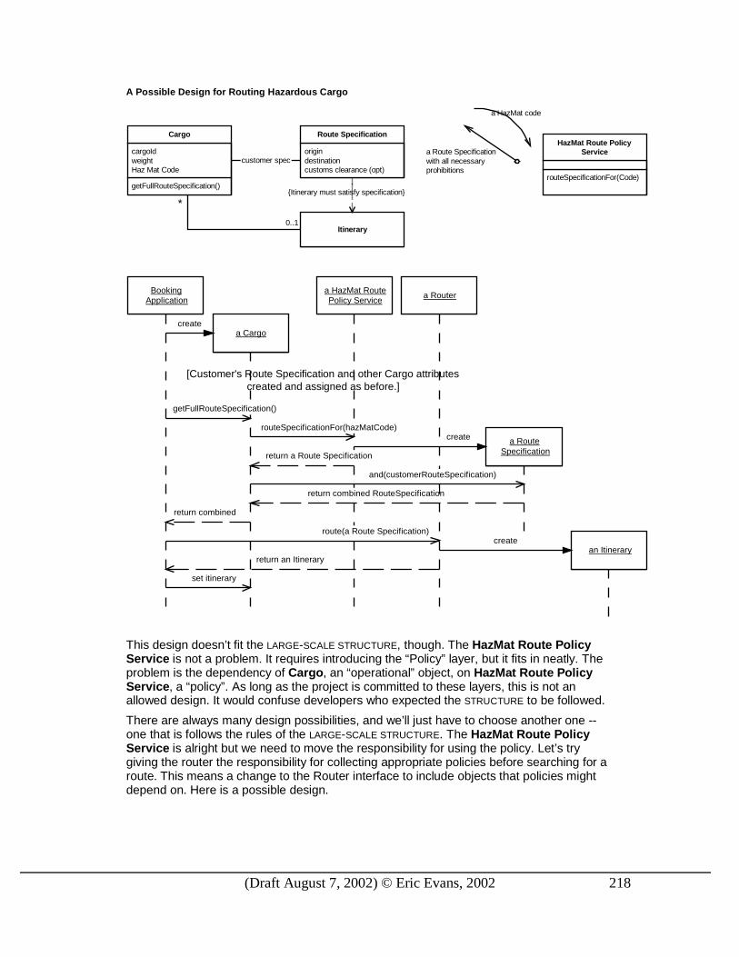
(Draft August 7, 2002) © Eric Evans, 2002 218
A Possible Design for Routing Hazardous Cargo
getFullRouteSpecification()
cargoIdweightHaz Mat Code
Cargo
origindestinationcustoms clearance (opt)
Route Specification
Itinerary
customer spec
0..1
{Itinerary must satisfy specification}
*
routeSpecificationFor(Code)
HazMat Route PolicyService
a HazMat code
a Route Specificationwith all necessaryprohibitions
BookingApplication
a RouteSpecification
a Cargo
a HazMat RoutePolicy Service
create
getFullRouteSpecification()
return an Itinerary
route(a Route Specification)
an Itinerary
a Router
createrouteSpecificationFor(hazMatCode)
set itinerary
[Customer's Route Specification and other Cargo attributescreated and assigned as before.]
return a Route Specification
and(customerRouteSpecification)
return combined RouteSpecification
return combined
create
This design doesn’t fit the LARGE-SCALE STRUCTURE, though. The HazMat Route Policy Service is not a problem. It requires introducing the “Policy” layer, but it fits in neatly. The problem is the dependency of Cargo, an “operational” object, on HazMat Route Policy Service, a “policy”. As long as the project is committed to these layers, this is not an allowed design. It would confuse developers who expected the STRUCTURE to be followed.
There are always many design possibilities, and we’ll just have to choose another one --one that is follows the rules of the LARGE-SCALE STRUCTURE. The HazMat Route Policy Service is alright but we need to move the responsibility for using the policy. Let’s try giving the router the responsibility for collecting appropriate policies before searching for a route. This means a change to the Router interface to include objects that policies might depend on. Here is a possible design.

(Draft August 7, 2002) © Eric Evans, 2002 219
A Design for Routing Hazardous Cargo Consistent with Layering
routeSpecificationFor(Code)
HazMat Route PolicyService
a HazMat code
a Route Specificationwith all necessaryprohibitions
cargoIdweightHaz Mat Code
Cargo origindestinationcustoms clearance (opt)
Route Specification
loadunload
Transport Leg
Itinerary
*
0..1
{Itinerary must satisfy specification}
a Cargo
an Itinerary satisfying thecustomer's Route Specificationand relevant routing policies
Customer
*
*
{ordered}
Decision
Support
Operations
Potential
Policy
route(Cargo):Itineraryroute(RouteSpecification):Itinerary
Router

(Draft August 7, 2002) © Eric Evans, 2002 220
BookingApplication
a RouteSpecification
a Cargo
a Router
create
return an Itinerary
route(a Cargo)
an Itinerary
a HazMat RoutePolicy Service
create
routeSpecificationFor(hazMatCode)
set itinerary
[Customer's Route Specification and other Cargo attributescreated and assigned as before.]
a Route Specification
and(customerRouteSpecification)
return combined RouteSpecification
create
getHazMatCode()
route(combined spec)
Now, this isn’t necessarily a better design than the other. They both have pros and cons. But if everyone on a project makes decisions in a consistent way, the design as a whole will be much more comprehensible, and that is worth some modest tradeoffs on detailed design choices.
If the structure were forcing many awkward design choices, then, in keeping with EVOLVING
ORDER, it should be evaluated and perhaps modified or even discarded.
<<For an additional example, could use banking and/or manufacturing.>>
Choosing appropriate layers
While these four layers are applicable to a range of enterprise systems, they do not capture the salient responsibilities of all domains. In other cases, it would be counterproductive to try to force the design into this shape, but there may be a natural set of responsibility layers that do work. For a domain completely unrelated to those we’ve discussed, these might have to be completely original. But when working with a new domain that has some similarity to those we’ve worked with before, we can often use responsibility layers we’ve used before, perhaps with a substitution or modification.
For example, as was mentioned above, the Potential layer is most prominent in businesses where capability is determined by capital investment, whereas, in financial services or insurance, to name two, the potential is to a large extent determined by current operations. An insurance company’s ability to take on a new risk by underwriting a new policy agreement is based on the diversification of its current business.

(Draft August 7, 2002) © Eric Evans, 2002 221
In these cases, what often comes to the fore is commitments made to customers. This suggests merging the Potential layer into the Operations layer and inserting a new layer below Policy which can handle the commitments that emerge through ongoing business.
• Commitment: What have we promised? : This layer has the nature of policy, in that it states goals that direct future operations, but it has the nature of operations in that commitments come about and are changed as a part of normal business activity.
Figure 3: Layers when operations determine resources (e.g. commercial lending)
Po
licyC
om
mitm
ent
Op
eration
Decisio
n
StrategiesConstraints(based on businessgoals or laws)
State reflecting businessreality
State reflecting businessreality (of activities)
Analytical Mechanisms Very little state, solittle change.
Slow state change.
Moderate rate of statechange.
Rapid state change.
Risk analysisPortfolio analysisNegotiation tools
...
Reserve limitsAsset allocation goals
...
Customer agreementsSyndication agreements
...
Status of outstanding loansAccrualsPayments and distributions
...
The rule of four
The Potential and Commitment layers are not mutually exclusive. A domain in which both were prominent, say a transportation company with a lot of custom shipping services, might use both. It is best to keep the layering system simple, though, and going beyond four or possibly five becomes unwieldy.
“ Tight” structure, constraining relationships between layers
These responsibility categories can help factor the model in a consistent way, but in some circumstances it is useful to go a step further. In addition to partitioning the responsibilities of the model, we can describe the relationships and possible communication paths between members of the different layers.
I’ve stated in a general way that lower layers should not know about higher ones, but until this point the decision as to how this should be done has been left to be made case-by-case during the modeling process. This is generally appropriate, but sometimes you may want to constrain the relationships between the layers more explicitly.
For example, intentional state-changes in the operations layer are made in accordance with the policy constraints. In a factory, a part will be routed to a machine that has the process capability called for in its recipe. But operations must reflect the real world, which means that sometimes the part will be put in the wrong machine. The real-world information must be accepted unconditionally. At this point we would like the system to strive to realign itself with policy, perhaps by rerouting the part to a repair process or scrap. But operations does not know anything about policy. What a spot.

(Draft August 7, 2002) © Eric Evans, 2002 222
One solution is to use an observer. Following this pattern, the operations objects broadcast events whenever their state changes. Policy layer objects listen for events from the lower layers. When an event occurs that violates a rule, the rule executes an action (which is part of the rule’s definition) that makes the appropriate response.
In the banking example above, the value of assets change (operations), shifting the value of segments of our portfolio. When these exceed portfolio allocation limits (policy), perhaps a trader is alerted, who can buy or sell assets to redress the balance.
Now, we could figure this out for each relationship, or we could decide once and for all that this is how policy and operations objects should interact. If we make a set of such constraints that govern the interactions, we’ ll have what I call a “ tight” structure. A tight structure is not practical in many situations. It may take away flexibility developers need, and may be difficult to apply across UNIFICATION CONTEXTS. But it does provide maximum consistency and allows some technical mechanisms to be standardized.
Figure 4: A structure that tightly constrains the design
Po
licyO
peratio
nP
oten
tialD
ecision
Su
pp
ort
Strategies [GHJV95]Constraints
State reflecting businessreality (of resources)
State reflecting businessreality (of activity)
Analytical Mechanisms
Possible ReferencesPossible Event
Channels
By specificationonly. No refs toinstances.
By callback sort ofmechanism only.
Very little state, solittle change.
Slow state change.
Rapid state change.
Moderate rate of statechange.
RESPONSIBILITY LAYERS can be applied in a variety of ways and at different tightness. The overriding issues are that it should give insight into the domain and that it should make development easier.
Identify the natural strata in the domain and assign them broad abstract responsibilities. Factor the responsibilities of objects and modules to fit within the responsibility of a specific layer . Define the relationships between layers to a tightness appropriate to your circumstances and then highlight exceptions to these relationships when they occur in the model.
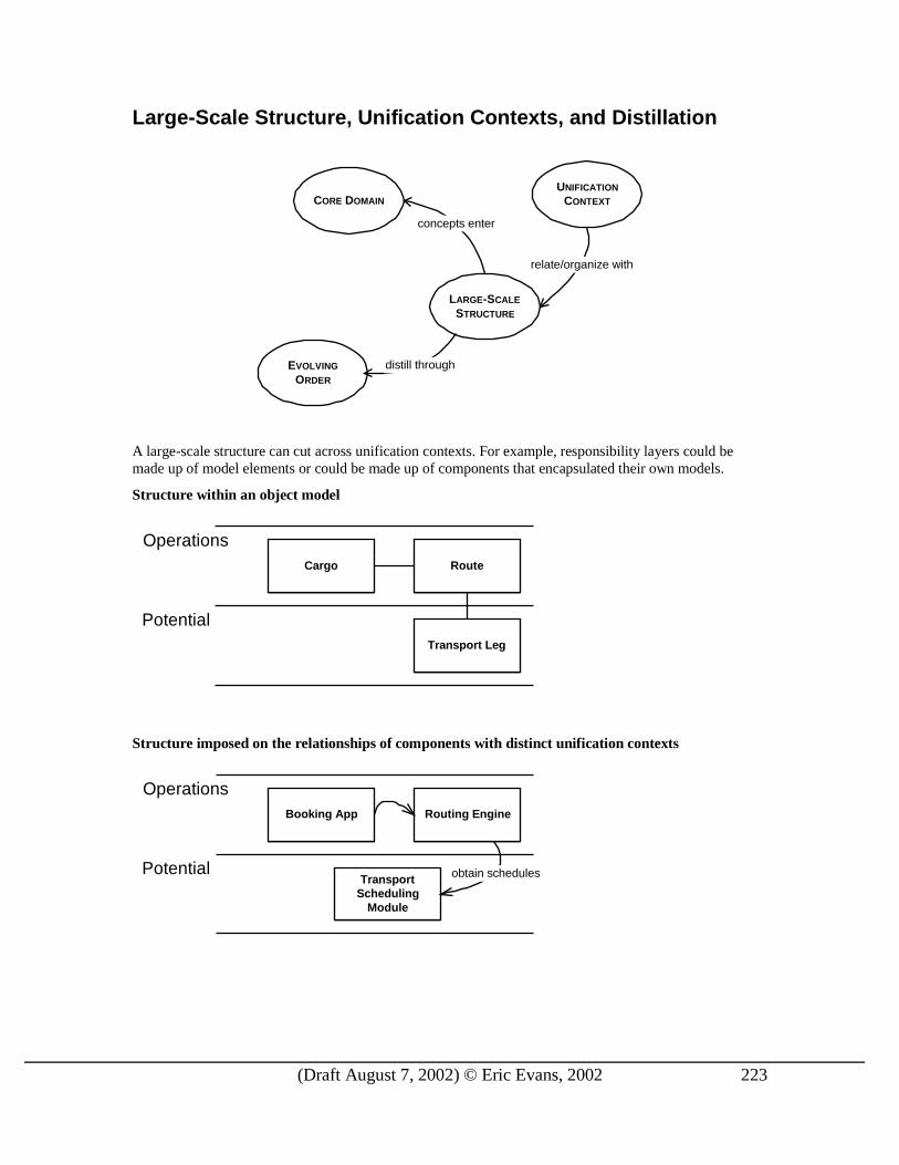
(Draft August 7, 2002) © Eric Evans, 2002 223
Large-Scale Structure, Unification Contexts, and Distillation
EVOLVING
ORDER
UNIFICATION
CONTEXT
LARGE-SCALE
STRUCTURE
CORE DOMAIN
distill through
concepts enter
relate/organize with
A large-scale structure can cut across unification contexts. For example, responsibility layers could be made up of model elements or could be made up of components that encapsulated their own models.
Structure within an object model
Operations
Potential
Cargo Route
Transport Leg
Structure imposed on the relationships of components with distinct unification contexts
Operations
Potential
Booking App Routing Engine
TransportScheduling
Module
obtain schedules

(Draft August 7, 2002) © Eric Evans, 2002 224
Structure that allows some components to span layers
Operations
Potential
ShippingCoordinationApplication
Routing Engine
obtain schedules
The interior of the Shipping Coordination Application could actually contain the object model illustrated in the RESPONSIBILITY LAYERS example.
In a similar way, large-scale structure is complimentary to distillation. The large-scale structure can help explain the relationships within the CORE DOMAIN and between generic subdomains.

(Draft August 7, 2002) © Eric Evans, 2002 225
Modules of the CORE DOMAIN (in bold) and GENERIC SUBDOMAINS are clar ified by the layers
At the same time, the large-scale structure itself may be an impor tant par t of the CORE DOMAIN. For example, the importance of distinguishing the layering of potential, operations, policy and decision support distills an important insight very fundamental to the business problem addressed by the software.
Refactoring Toward a Fitting Structure In an era when the industry is shaking off excessive up-front design, some will see large-scale structure as a throwback to the bad old days of waterfall architecture. But, in fact, the only way a useful structure can be found is from a very deep understanding of the domain and the problem, and the practical way to that understanding is an iterative development process.
(Draft August 7, 2002) © Eric Evans, 2002 226
A team committed to EVOLVING ORDER must fearlessly rethink the large-scale structure throughout the project lifecycle. The team should not saddle itself with a structure conceived of early on when no one understands the domain or the requirements very well.
Unfortunately, that means that your final structure will not be available at the start, and that means that you will have to refactor to impose it as you go along. This can be expensive and difficult, but it is necessary. There are some general ways of controlling the cost and maximizing the gain.
Minimalism
One key to keeping the cost down is keep the structure simple and light-weight. Don’t attempt to be comprehensive. Just address the most serious concerns and leave the rest to be handled on a case-by-case basis.
Early on, it can be helpful to choose a loose structure, such as a SYSTEM METAPHOR or RESPONSIBILITY
LAYERS. A minimal, weak structure can provide light-weight guidelines that will nonetheless help prevent chaos.
Communication and Self-Discipline
First, it is necessary to follow the structure in new development and refactoring. To do this, the structure must be understood by the entire team. The terminology and relationships must enter the UBIQUITOUS LANGUAGE.
Large-scale structure can provide a vocabulary for the project to deal with the system broadly, and for different people to independently make harmonious decisions. But since most large-scale structures are loose conceptual guidelines, the teams must exercise self-discipline.
Without consistent adherence by the many people involved, structures have a tendency to decay. The relationship of the structure to detailed parts of the model or implementation is not usually explicit in the code, and functional tests do not rely on the structure. Plus, the structure tends to be abstract, so that consistency of application can be difficult to maintain across a large team (or multiple teams).
Normal discussion is not usually enough to produce the level of communication needed for a team to maintain a consistent large-scale structure in a system. Therefore it is critical for everyone to incorporate it into the UBIQUITOUS LANGUAGE of the project.
Restructuring Yields Supple Design
Second, any change to the structure may lead to a lot of refactoring. Since the structure is evolving (as system complexity increases and understanding deepens) the entire system has to be changed to adhere to the new structure as it changes. Obviously that is a lot of work, as the system grows.
One hopeful discovery that I’ve made is that a design with a large-scale structure is usually much easier to transform than one without. This seems to be true even when changing from one kind of structure to another, say METAPHOR to LAYERS. I can’ t entirely explain this. Part of the answer is that it is easier to rearrange something when you can understand its current arrangement, and the preexisting structure makes that easier. Partly it is that the discipline that it took to maintain the earlier structure filters through all aspects of the system. But there is something more, I think, because it is even easier to change a system that has had two previous structures.
A new leather jacket is stiff and uncomfortable, but after the first day of wear the elbows have been bent a few times and are easier to bend. After a few more wearings, the shoulders have loosened up, and the jacket is easier to put on. After months of wear, the leather becomes supple and is comfortable and easy to move in. So it seems to be with models that are transformed repeatedly with conceptually sound transformations. Ever increasing knowledge is embedded into them and the pr inciple axes of change have been identified and made flexible, while stable aspects have been simplified.

(Draft August 7, 2002) © Eric Evans, 2002 227
Distillation Lightens the Load
Another crucial force that should be applied to the model is continuous distillation. This reduces the difficulty of changing the structure in various ways. First, by removing mechanisms, GENERIC SUBDOMAINS and other support structure from the CORE DOMAIN, there may simply be less to restructure.
If possible, these supporting elements should be defined to fit into the large-scale structure in a simple way. For example, in a system of RESPONSIBILITY LAYERS, a GENERIC SUBDOMAIN could be defined that would fit within a single layer. With PLUGGABLE COMPONENTS, it could be a component, be owned entirely by a single component, or be a SHARED KERNEL between a set of related components. This means that these supporting elements may also have to be refactored to find their place in the structure, but they move independently of the CORE DOMAIN, and tend to be more narrowly focused. And ultimately they are less critical.
The principles of distillation and refactoring toward deeper insight apply even to the large-scale structure itself. For example, the layers may be initially chosen based on a superficial understanding of the domain, and are gradually replaced with deeper abstractions that express the fundamental responsibilities of the system. This sharp-edged clarity that lets people easily see deep into the design is the goal, and it also is part of the means, since it makes manipulation of the system on a large-scale easier and safer.
Architecture, Architecture Teams, and Large-Scale Structure Effective software development is a highly dynamic process. When the highest level of decisions is set in stone, the team has fewer options when it must respond to change. EVOLVING ORDER addresses this by emphasizing ongoing change to the large-scale structure in response to deepening insight. This still leaves the question of who makes these decisions.
When too many design decisions are preordained, the development team can be hobbled, without the flexibility to solve the problems they are charged with. So, while some harmonizing principle can be valuable, it must grow and change with the ongoing life of the development project, and it must not take too much power away from the application developers, whose job is hard enough as it is.
Creating an organizing principle, or LARGE-SCALE STRUCTURE, of this subtlety requires a really deep understanding of the needs of the project and the concepts of the domain. The only people who have that depth of knowledge are the members of the application development team. This is why application architectures created by architecture teams are so seldom helpful, in spite of the undeniable talent of many of the architects.
Yet design at this level calls for sophistication that is probably in short supply. Besides, the large-scale structure may be shared among several teams, so some centralization of decision making may be needed.
Projects have tried many approaches to resolve this. They seem to get mixed success depending on circumstances. The options fall generally into the following categories.
Emergent Structure from Application Development
A team capable of doing these things must be disciplined, it must have very good communication. Such a team can use evolving order to arrive at a shared set of principles to operate from so that order is organic rather than imposed by fiat.
This is the typical model for an Extreme Programming team. The structure may emerge completely spontaneously from the insight of any programming pair. More often, having an individual or a subset of the team with some oversight responsibility for large-scale structure helps keep the structure unified. This works particularly if this person is a hands-on developer on the team and is not considered the source of all such decisions so much as an arbiter and communicator. On the Extreme Programming teams I have seen, such strategic design leadership seems to have emerged naturally, often in the person of the coach.
When a large-scale structure spans multiple teams, informal collaboration of members of closely affiliated teams may emerge.
(Draft August 7, 2002) © Eric Evans, 2002 228
Therefore,
Let the structure emerge from the development team itself, according to need, rather than by fiat from a separate architectural team. Provide the development team with the necessary talent to pull this off.
It follows that the development team must have at least a few people of the caliber to make design decisions that will affect the whole project. You can’t siphon off all the best and brightest to architecture teams or technical infrastructure.
Application Coordination Committee
This is variant of the emergent structure approach. It arises when there are multiple teams that want to use the same structure and need a little more formal coordination. The discoveries that lead to the idea for a large-scale structure still happen on an application team, but then it is discussed with representatives of the various teams. After assessing the impact, they may decide to adopt it, or modify it, or leave it on the table. All the teams attempt to move together in this loose affiliation.
This can work when there are relatively few teams, when they are all committed to coordinating with each other, when their design capabilities are comparable, and when their structural needs are similar enough to be met by a single large-scale structure.
Customer Focused Architecture Team
Traditionally, architecture is handed down, developed before application development begins, from a team that has more power in the organization than the application development team. But it doesn’ t have to be that way.
An architecture team can act as a peer with various application teams, helping to coordinate and harmonize their large-scale structures as well as UNIFICATION CONTEXT boundaries and other cross-team technical issues. To be useful in this, they must have a mindset that emphasizes application development.
Unlike technical infrastructure and architectures, developing domain architecture does not involve writing a lot of code. What it does require is listening. An experienced architect may be able to take ideas coming from various teams and facilitate the development of a generalized solution.
Minimalism is even more critical for an architecture team. They will have less feel for the obstacles they might be placing in front of application teams. At the same time, their enthusiasm for their primary responsibility makes them more likely to get carried away. I’ve seen this many times, and it has happened to me too. One good idea leads to another and we end up with an overbuilt architecture that is counter-productive. Instead, we have to focus on producing a large-scale structure that is ruthlessly minimalist, containing nothing that does not significantly improve the clarity of the design.
Architecture Team Member on Application Team
This is a variant of the customer focused architecture team. By actually circulating team members between the architecture team and various application teams knowledge can be spread, communication improved, and a real understanding of application development can be instilled in the architecture team.
Watch Out With the Technical Architecture, Too
Technical architectures can greatly accelerate application development, including the DOMAIN LAYER, by providing an INFRASTRUCTURE LAYER that frees the application from implementing basic services, and by helping to isolate the domain from other concerns. But there is a risk that an architecture can interfere with expressive implementations of the domain model and easy change. This can happen even when the architects had no intention of venturing into the domain or application layers.
The same biases that limit the downside of large-scale structure can help with technical architecture. Evolution, minimalism, and involvement with the application development team can lead to a continuously refined set of services and rules that genuinely help application development without getting in the way. Architectures that don’ t follow this path will either stifle the creativity of application development or will

(Draft August 7, 2002) © Eric Evans, 2002 229
find their architecture circumvented, leaving application development, for practical purposes, with no architecture at all.
<<SIDE BAR>>
A group of architects (the kind who design physical buildings), led by Christopher Alexander, were advocates of piecemeal growth in the realm of architecture and city planning. They explained very nicely why master plans fail.
Without a planning process of some kind, there is not a chance in the world that the University of Oregon will ever come to possess an order anywhere near as deep and harmonious as the order that underlies the University of Cambridge. The master plan has been the conventional way of approaching this difficulty. The master plan attempts to set down enough guidelines to provide for coherence in the environment as a whole – and still leave freedom for individual buildings and opens spaces to adapt to local needs. …and all the various parts of this future university will form a coherent whole, because they were simply plugged into the slots of the design. …in practice master plans fail – because they create totalitarian order, not organic order. They are too rigid; they cannot easily adapt to the natural and unpredictable changes that inevitably arise in the life of a community. As these changes occur… the master plan becomes obsolete, and is no longer followed. And even to the extent that master plans are followed…they do not specify enough about connections between buildings, human scale, balanced function, etc. to help each local act of building and design become well-related to the environment as a whole. …The attempt to steer such a course is rather like filling in the colors in a child’s coloring book… At best, the order which results from such a process is banal. …Thus, as a source of organic order, a master plan is both too precise, and not precise enough. The totality is too precise: the details are not precise enough. …the existence of a master plan alienates the users [since, by definition] the members of the community can have little impact on the future shape of their community because most of the important decisions have already been made. The Oregon Experiment, 1975 (pp. 16-28), [ASAIA1975]
They advocate instead a set of principles that all community members apply to every act of piecemeal growth, so that “organic order” emerges, well adapted to circumstances.
<<END SIDE BAR>>

(Draft August 7, 2002) © Eric Evans, 2002 230
18. Game Plans I’ve presented a lot of principles and techniques for domain driven development. So how do you put it all together? What do you do first? Second? Third? In this section I’ ll outline a few plans based on typical scenarios. These are meant to give ideas, but you will have to analyze your situation and decide which tools are needed in the situation.
A project well under way.
When I go into a project that is already in full swing, I tend to attack in a fairly consistent sequence.
1. Understand the domain vision, ideally finding or writing a DOMAIN VISION STATEMENT.
2. Clarify the UNIFICATION CONTEXTS.
3. Identify the technology for implementing business rules (coding in the objects, external rules engine, etc.).
4. Establish a UBIQUITOUS LANGUAGE.
Recognizing that none of these will be “ right” at first, and that they can and should all be refined later with deepened insight, an initial pass at these steps usually positions the team to focus and progress on the domain design.
Green Field (A brand new project)
In the excitement of a new project, ambitions soar (as they should). Everything has to be done, and we want to do everything right. Where should we focus at this early stage?
1. Distillation. Identify the CORE DOMAIN. Write an initial DOMAIN VISION STATEMENT.
2. Launch the UBIQUITOUS LANGUAGE in the process of making a first cut model of the CORE
DOMAIN.
3. Emphasize the process of refactoring toward deeper insight.
4. Make the Language of Model Driven Design part of the coding standard.
New Project Legacy Replacement
This has elements of the Green Field along with elements of Phasing Out a Legacy System (p. xx).
<<Readers: This section still needs lots of work. Might end up getting cut.
How important do you think it is?>>
(Draft August 7, 2002) © Eric Evans, 2002 233
References [AIS1977] Alexander, C., Ishikawa, S., Silverstein, M. 1977. A
Pattern Language: Towns, Buildings, Construction. Oxford University Press.
[ASAIA1975] Alexander, C., Silverstein, M., Angel, S., Ishikawa, S., Abrams, D. 1975. The Oregon Experiment. Oxford University Press.
[ABW1998] Alpert, S., Brown, K., Woolf, B. 1998. The Design Patterns Smalltalk Companion. Addison-Wesley.
[Beck2000] Beck, K., 2000. Extreme Programming Explained, Embrace Change. Addison-Wesley.
[BMRSS1996] Buschmann, F., Meunier, R., Rohnert, H., Sommerlad, P., and Stal, M. 1996. P. Pattern-Oriented Software Architecture: A System of Patterns. Wiley.
[Cockburn1998] Cockburn, A., 1998. Surviving Object-Oriented Projects. Addison-Wesley.
[EF1997] Evans, E., Fowler, M. 1997, “Specifications”, Proceedings of PLoP 97 Conference.
[FJ2000] Fayad, M., Johnson, R. 2000. Domain-Specific Application Frameworks. Wiley.
[Fowler1996] Fowler, M., 1996. Analysis Patterns: Reusable Object Models. Addison-Wesley.
[Fowler1999] Fowler, M., 1999. Refactoring: Improving the Design of Existing Code. Addison-Wesley.
[Fowler2003] Fowler, M., 2003. Enterprise Application Architecture Patterns( ???). Addison-Wesley.
[GHJV1995] Gamma, E., Helm, R., Johnson, R., and Vlissides, J. 1995. Design Patterns. Addison-Wesley.
[MRL1995] Murray-Rust, P., Rzepa, H., Leach, C. Abstract 40. Presented as a poster at the 210th ACS Meeting in Chicago on 21 August 1995. http://www.ch.ic.ac.uk/cml/
[Kerievsky2001] Kerievsky, J. 2001, “Continuous Learning” , Proceedings of XP 2001 Conference.
[Larman1998] Larman, C. 1998. Applying UML and Patterns: An Introduction to Object-Oriented Analysis and Design. Prentice Hall.