domain name system for peerhosting - trinity college … · domain name system for peerhosting ......
TRANSCRIPT

Domain Name System for PeerHosting
Arnav Aggarwal, B.Tech
A dissertation submitted to the University of Dublin,in partial fulfilment of the requirements for degree of
Master of Science in Computer Science
2010

Declaration
I declare that the work described in this dissertation is, except where otherwise stated, entirely myown work and has not been submitted as an exercise for a degree at this or any other university.
Arnav Aggarwal, B.TechSeptember 13, 2010
i

Permission to lend and/or copy
I agree that Trinity College Library may lend or copy this dissertation upon request.
Arnav Aggarwal, B.TechSeptember 13, 2010
ii

Abstract
With exponential increase in web content on the world wide web, it is becoming increasing expensive and chal-lenging for the Web Hosting Providers to ensure strict QOS. Peerhosting platform is an open, self balancingcluster of Web Hosting Provider web servers which collaborate to host content collectively while reducing thecost of managing and hosting web content. It interleaves content distribution management and client redirec-tion services to ensure content availability. The current implementation of redirection service is centralisedhence it is a single point of failure and a potential bottleneck.
To ensure efficient content availability there is a need to design a service which integrates well with thePeerhosting platform to resolve the current content location while observing current state of individual HPs.Peerhosting dns solves this problem by using a pastry routing protocol to improve scalability and enable loaddistribution among multiple nodes. The result is a fully operational name service which offers average lookuplatency comparable to that of legacy dns.
iii

Acknowledgements
My sincere thanks go out to all those who helped and supported me during the development of this project, notleast my excellent supervisor, Dr. Stephen Barrett helped me throughout the project duration. The success ofthis project relied on both his advice and calming influence throughout. A special thanks to Paul Laird for allhis help and insight into Peerhosting requirements and other things. Finally, thanks to all my NDS classmatesand Dr. Siobhan Clarke for guiding us throughout our course. I feel blessed to be part of NDS, this year hasbeen the best year of my life!
iv

Contents
1 Introduction 21.1 Motivation . . . . . . . . . . . . . . . . . . . . . . . . . . . . . . . . . . . . . . . . . . . . . 21.2 PeerHosting Service . . . . . . . . . . . . . . . . . . . . . . . . . . . . . . . . . . . . . . . 21.3 Research Objective . . . . . . . . . . . . . . . . . . . . . . . . . . . . . . . . . . . . . . . . 21.4 Detailed Hypotheses . . . . . . . . . . . . . . . . . . . . . . . . . . . . . . . . . . . . . . . 31.5 Outline . . . . . . . . . . . . . . . . . . . . . . . . . . . . . . . . . . . . . . . . . . . . . . 4
2 State of the Art 52.1 Legacy DNS . . . . . . . . . . . . . . . . . . . . . . . . . . . . . . . . . . . . . . . . . . . . 5
2.1.1 Overview . . . . . . . . . . . . . . . . . . . . . . . . . . . . . . . . . . . . . . . . . 52.1.2 Structure and delegation . . . . . . . . . . . . . . . . . . . . . . . . . . . . . . . . . 52.1.3 Name resolution . . . . . . . . . . . . . . . . . . . . . . . . . . . . . . . . . . . . . 62.1.4 Caching . . . . . . . . . . . . . . . . . . . . . . . . . . . . . . . . . . . . . . . . . . 72.1.5 DNSSEC . . . . . . . . . . . . . . . . . . . . . . . . . . . . . . . . . . . . . . . . . 72.1.6 Legacy DNS challenges . . . . . . . . . . . . . . . . . . . . . . . . . . . . . . . . . 8
2.2 Distributed Hash Table based Technologies . . . . . . . . . . . . . . . . . . . . . . . . . . . 92.2.1 Overview . . . . . . . . . . . . . . . . . . . . . . . . . . . . . . . . . . . . . . . . . 92.2.2 Implementations and protocols . . . . . . . . . . . . . . . . . . . . . . . . . . . . . 102.2.3 Characteristics . . . . . . . . . . . . . . . . . . . . . . . . . . . . . . . . . . . . . . 102.2.4 Performance metrics . . . . . . . . . . . . . . . . . . . . . . . . . . . . . . . . . . . 112.2.5 Pastry . . . . . . . . . . . . . . . . . . . . . . . . . . . . . . . . . . . . . . . . . . . 12
2.3 DDNS . . . . . . . . . . . . . . . . . . . . . . . . . . . . . . . . . . . . . . . . . . . . . . . 132.3.1 Overview . . . . . . . . . . . . . . . . . . . . . . . . . . . . . . . . . . . . . . . . . 132.3.2 Operation . . . . . . . . . . . . . . . . . . . . . . . . . . . . . . . . . . . . . . . . . 132.3.3 Advantages . . . . . . . . . . . . . . . . . . . . . . . . . . . . . . . . . . . . . . . . 142.3.4 Challenges . . . . . . . . . . . . . . . . . . . . . . . . . . . . . . . . . . . . . . . . 15
2.4 CoDoNS . . . . . . . . . . . . . . . . . . . . . . . . . . . . . . . . . . . . . . . . . . . . . . 152.4.1 Overview . . . . . . . . . . . . . . . . . . . . . . . . . . . . . . . . . . . . . . . . . 152.4.2 Beehive . . . . . . . . . . . . . . . . . . . . . . . . . . . . . . . . . . . . . . . . . . 152.4.3 Operation . . . . . . . . . . . . . . . . . . . . . . . . . . . . . . . . . . . . . . . . . 172.4.4 Characteristics . . . . . . . . . . . . . . . . . . . . . . . . . . . . . . . . . . . . . . 172.4.5 Challenges . . . . . . . . . . . . . . . . . . . . . . . . . . . . . . . . . . . . . . . . 182.4.6 Relevance . . . . . . . . . . . . . . . . . . . . . . . . . . . . . . . . . . . . . . . . . 18
3 System requirements and architecture 203.1 Peerhosting . . . . . . . . . . . . . . . . . . . . . . . . . . . . . . . . . . . . . . . . . . . . 20
3.1.1 Overview . . . . . . . . . . . . . . . . . . . . . . . . . . . . . . . . . . . . . . . . . 203.1.2 Stakeholders . . . . . . . . . . . . . . . . . . . . . . . . . . . . . . . . . . . . . . . 213.1.3 Operation . . . . . . . . . . . . . . . . . . . . . . . . . . . . . . . . . . . . . . . . . 21
v

CONTENTS
3.1.4 Challenges . . . . . . . . . . . . . . . . . . . . . . . . . . . . . . . . . . . . . . . . 223.2 DNS Requirements . . . . . . . . . . . . . . . . . . . . . . . . . . . . . . . . . . . . . . . . 22
3.2.1 Primary Goals . . . . . . . . . . . . . . . . . . . . . . . . . . . . . . . . . . . . . . 233.2.2 Secondary Goals . . . . . . . . . . . . . . . . . . . . . . . . . . . . . . . . . . . . . 233.2.3 Stretch Goal . . . . . . . . . . . . . . . . . . . . . . . . . . . . . . . . . . . . . . . 24
3.3 Proposed System Design . . . . . . . . . . . . . . . . . . . . . . . . . . . . . . . . . . . . . 243.3.1 System Overview . . . . . . . . . . . . . . . . . . . . . . . . . . . . . . . . . . . . . 243.3.2 System Architecture and components . . . . . . . . . . . . . . . . . . . . . . . . . . 253.3.3 Introduction to Past . . . . . . . . . . . . . . . . . . . . . . . . . . . . . . . . . . . . 293.3.4 Object Identifier Generation . . . . . . . . . . . . . . . . . . . . . . . . . . . . . . . 303.3.5 Storage Load Balancing and Replication . . . . . . . . . . . . . . . . . . . . . . . . . 303.3.6 Storage Mechanism . . . . . . . . . . . . . . . . . . . . . . . . . . . . . . . . . . . . 313.3.7 Caching . . . . . . . . . . . . . . . . . . . . . . . . . . . . . . . . . . . . . . . . . . 323.3.8 Performance Engine . . . . . . . . . . . . . . . . . . . . . . . . . . . . . . . . . . . 32
4 Implementation 344.1 Language and environment . . . . . . . . . . . . . . . . . . . . . . . . . . . . . . . . . . . . 344.2 System Implementation . . . . . . . . . . . . . . . . . . . . . . . . . . . . . . . . . . . . . . 34
4.2.1 Continuations . . . . . . . . . . . . . . . . . . . . . . . . . . . . . . . . . . . . . . . 354.2.2 Environment . . . . . . . . . . . . . . . . . . . . . . . . . . . . . . . . . . . . . . . 354.2.3 Usage of Pastry . . . . . . . . . . . . . . . . . . . . . . . . . . . . . . . . . . . . . . 364.2.4 Resource record selection . . . . . . . . . . . . . . . . . . . . . . . . . . . . . . . . 37
4.3 System Components . . . . . . . . . . . . . . . . . . . . . . . . . . . . . . . . . . . . . . . 374.3.1 Bootstrap Node . . . . . . . . . . . . . . . . . . . . . . . . . . . . . . . . . . . . . . 384.3.2 Standard Node . . . . . . . . . . . . . . . . . . . . . . . . . . . . . . . . . . . . . . 384.3.3 Insert Gateway . . . . . . . . . . . . . . . . . . . . . . . . . . . . . . . . . . . . . . 394.3.4 Insert Performance Gateway . . . . . . . . . . . . . . . . . . . . . . . . . . . . . . . 404.3.5 Query Gateway . . . . . . . . . . . . . . . . . . . . . . . . . . . . . . . . . . . . . . 404.3.6 Insert client . . . . . . . . . . . . . . . . . . . . . . . . . . . . . . . . . . . . . . . . 414.3.7 Insert Performance client . . . . . . . . . . . . . . . . . . . . . . . . . . . . . . . . . 414.3.8 Query client . . . . . . . . . . . . . . . . . . . . . . . . . . . . . . . . . . . . . . . . 41
5 Evaluation 425.1 Introduction to evaluation . . . . . . . . . . . . . . . . . . . . . . . . . . . . . . . . . . . . . 425.2 Evaluation system configuration . . . . . . . . . . . . . . . . . . . . . . . . . . . . . . . . . 42
5.2.1 software configuration . . . . . . . . . . . . . . . . . . . . . . . . . . . . . . . . . . 425.2.2 Hardware configuration . . . . . . . . . . . . . . . . . . . . . . . . . . . . . . . . . 435.2.3 Network Configuration . . . . . . . . . . . . . . . . . . . . . . . . . . . . . . . . . . 43
5.3 Design of evaluation system . . . . . . . . . . . . . . . . . . . . . . . . . . . . . . . . . . . 445.3.1 Introduction to design of evaluation system . . . . . . . . . . . . . . . . . . . . . . . 445.3.2 Evaluation of Peerhosting DNS . . . . . . . . . . . . . . . . . . . . . . . . . . . . . 44
5.4 Implementation of evaluation system . . . . . . . . . . . . . . . . . . . . . . . . . . . . . . . 445.4.1 Basic Test Infrastructure . . . . . . . . . . . . . . . . . . . . . . . . . . . . . . . . . 445.4.2 Query Latency . . . . . . . . . . . . . . . . . . . . . . . . . . . . . . . . . . . . . . 44
5.5 Evaluation results . . . . . . . . . . . . . . . . . . . . . . . . . . . . . . . . . . . . . . . . . 465.5.1 LAN test with no replication . . . . . . . . . . . . . . . . . . . . . . . . . . . . . . . 465.5.2 LAN test with five replicas . . . . . . . . . . . . . . . . . . . . . . . . . . . . . . . . 475.5.3 LAN test with ten replicas . . . . . . . . . . . . . . . . . . . . . . . . . . . . . . . . 485.5.4 Delay range comparison . . . . . . . . . . . . . . . . . . . . . . . . . . . . . . . . . 49
vi

CONTENTS
5.5.5 PlanetLab test with no replicas . . . . . . . . . . . . . . . . . . . . . . . . . . . . . . 505.5.6 PlanetLab test with five replicas . . . . . . . . . . . . . . . . . . . . . . . . . . . . . 515.5.7 Comparison of delay range . . . . . . . . . . . . . . . . . . . . . . . . . . . . . . . . 51
5.6 Evaluation conclusion . . . . . . . . . . . . . . . . . . . . . . . . . . . . . . . . . . . . . . . 52
6 Conclusions 546.1 Introduction . . . . . . . . . . . . . . . . . . . . . . . . . . . . . . . . . . . . . . . . . . . . 546.2 Conclusions . . . . . . . . . . . . . . . . . . . . . . . . . . . . . . . . . . . . . . . . . . . . 546.3 Future work . . . . . . . . . . . . . . . . . . . . . . . . . . . . . . . . . . . . . . . . . . . . 55
6.3.1 Peerhosting integration . . . . . . . . . . . . . . . . . . . . . . . . . . . . . . . . . . 556.3.2 PlanetLabs testing . . . . . . . . . . . . . . . . . . . . . . . . . . . . . . . . . . . . 556.3.3 DNS protocol . . . . . . . . . . . . . . . . . . . . . . . . . . . . . . . . . . . . . . . 556.3.4 Delegation authority . . . . . . . . . . . . . . . . . . . . . . . . . . . . . . . . . . . 556.3.5 Security layer . . . . . . . . . . . . . . . . . . . . . . . . . . . . . . . . . . . . . . . 556.3.6 Caching layer . . . . . . . . . . . . . . . . . . . . . . . . . . . . . . . . . . . . . . . 556.3.7 Monitoring tools . . . . . . . . . . . . . . . . . . . . . . . . . . . . . . . . . . . . . 56
6.4 Lessons learned . . . . . . . . . . . . . . . . . . . . . . . . . . . . . . . . . . . . . . . . . . 56
vii
List of Figures
1.1 Peerhosting Architecture[2] . . . . . . . . . . . . . . . . . . . . . . . . . . . . . . . . . . . 3
2.1 Resolver in legacy DNS . . . . . . . . . . . . . . . . . . . . . . . . . . . . . . . . . . . . . . 62.2 Secure DNS query and response . . . . . . . . . . . . . . . . . . . . . . . . . . . . . . . . . 72.3 Pastry routing table . . . . . . . . . . . . . . . . . . . . . . . . . . . . . . . . . . . . . . . . 122.4 [23] Chord ring showing the responsibility of keys . . . . . . . . . . . . . . . . . . . . . . . . 142.5 Replication level in Beehive system . . . . . . . . . . . . . . . . . . . . . . . . . . . . . . . 162.6 CoDoNS System . . . . . . . . . . . . . . . . . . . . . . . . . . . . . . . . . . . . . . . . . 18
3.1 Peerhosting Architecture . . . . . . . . . . . . . . . . . . . . . . . . . . . . . . . . . . . . . 203.2 Peerhosting DNS Architecture . . . . . . . . . . . . . . . . . . . . . . . . . . . . . . . . . . 253.3 Insert dns resource record with replication factor of four . . . . . . . . . . . . . . . . . . . . 263.4 Insert performance statistics from HPs in Peerhosting DNS . . . . . . . . . . . . . . . . . . . 273.5 DNS query resolution operation . . . . . . . . . . . . . . . . . . . . . . . . . . . . . . . . . 28
5.1 Query delay observed when replication factor (k) equals zero . . . . . . . . . . . . . . . . . . 465.2 Query delay observed when replication factor (k) equals five . . . . . . . . . . . . . . . . . . 475.3 Query delay observed when replication factor (k) equals ten . . . . . . . . . . . . . . . . . . 485.4 Query delay comparison observed on local area network . . . . . . . . . . . . . . . . . . . . 495.5 Query delay observed when replication factor (k) equals zero on PlanetLab nodes . . . . . . . 505.6 Query delay observed when replication factor(k) equals five on PlanetLab nodes . . . . . . . . 515.7 comparison . . . . . . . . . . . . . . . . . . . . . . . . . . . . . . . . . . . . . . . . . . . . 52
1

Chapter 1
Introduction
1.1 Motivation
In recent years, we have seen dramatic increase in popularity of web based applications such as Facebook,Youtube and Google applications. A large number of businesses are solely Internet based and many othersdepend on Internet for a large number of reasons such as internal and external connectivity. As a result webHosting Delivery is becoming mission critical for the success of the businesses. These factors coupled with theshift towards using web applications has increased the complexity of existing networks making it difficult forthe web hosting providers to ensure content delivery with consistent QOS across different geographic regions.
[2]The hosting providers are faced with two key issues. First, flash crowd problem and the distributeddenial of service attacks often cause the networks to be overloaded. Second, the growing scale of internet ismaking it increasingly infeasible for the hosting providers to match in-house usage to the available capacity.Both these challenges need to be addressed in both the core Peerhosting platform as well its name resolutionservice.
1.2 PeerHosting Service
Web Hosting provision has become very complex and increasingly costly with the increase in the complexityof systems and the need to account for sudden and huge bandwidth requirements. To solve this problem ,[2] the Peerhosting platform aims to enable a worldwide, open and self-balancing cluster of Website HostingProvider web servers, provided by different organisations, which can safely collaborate to deliver web contentmore efficiently. It delivers a broker service which enables trade in hosting capacity among participating HPsand orchestrates delivery of web content using peer to peer model. The Peerhosting system needs to integrateflawlessly with the existing client technologies and should be transparent to the its clients.
1.3 Research Objective
Currently the Peerhosting model is dependent on the use of a centralised database for name resolution service.This implementation of resolution service has significant drawbacks. First, it offers limited scalability andflexibility. Second, it does not support fast propagation updates from HPs. Third, it is a central point offailure and a potential bottleneck. These factors coupled with high latency, load imbalance and centralisedmechanism has significant performance and security implications on the success of the Peerhosting platform. Itis therefore essential that the target service be able able to distribute load among multiple hosts while enablingfast propagation updates from HPs. The project aims to contemplate and construct a domain name service
2

CHAPTER 1. INTRODUCTION
Figure 1.1: Peerhosting Architecture[2]
which integrates with [2] peerhosting platform and satisfies above stated requirements while offering nameresolution service with delay times comparable to legacy DNS.
1.4 Detailed Hypotheses
To achieve the goals of this dissertation, a domain name resolution service for the Peerhosting platform will beinvestigated into, leading to the its implementation and evaluation. The known metrics for evaluation are queryresolution time, replication efficiency, caching feasibility, load balancing and dynamic update propagation.The service would offer a name resolution service designed specifically to cater to the needs of the Peerhostingplatform while providing some control over resource distribution to content providers. The service will be basedon a completely decentralised, distributed architecture which would offer high scalability, low latency, naturalresistance to flooding attacks, fast update propagation and improved load balancing. We discuss some of thepeer to peer based name resolution services which satisfy some of the requirements of the peerhosting platformi.e.[21] CoDoNS and [6] DDNS. These systems will be studied and evaluated to design a service specific tothe requirements of peerhosting platform. Our initial hypotheses is that peer to peer routing protocols basedon structured distributed hash table (DHTs) might be a reasonable approach for constructing a domain nameservice. Therefore we will study some approaches before initiating the design of a name resolution service.
3

CHAPTER 1. INTRODUCTION
1.5 Outline
Chapter Two discusses the background of Peerhosting, legacy DNS service, various DHT protocols and sev-eral peer based DNS services which might be relevant to this project. The above mentioned technologies havebeen studied and reviewed and they act as the foundation for designing an appropriate name resolution servicein the design chapter.
Chapter Three delves into the design of a domain name service for Peerhosting platform, this chapter coversa detailed explanation of Peerhosting, name service requirements along with a system design which satisfiesabove described requirements.
Chapter Four lists the steps taken to implement the Peerhosting domain name service, concentrating on nu-merous system components and libraries used.
Chapter Five evaluates Peerhosting DNS. In this chapter a test suite is designed and implemented whichis used to evaluate the performance of the Peerhosting DNS implementation. Comparisons are drawn withlegacy DNS system and approximations done for Peerhosting DNS system comprising several thousand nodes.
Chapter Six concludes the report and suggests future work for a better implementation of the Peerhostingplatform.
4

Chapter 2
State of the Art
This chapter describes the current state of the art in the areas of domain name system (DNS), Distributed hashtable (DHT) and peer based domain name systems. In particular, various applications and implementations ofthe distributed hash tables will be discussed in view of their suitability and relevance to the cause of designingthe domain name resolution in [2] Peerhosting model. The chapter also documents metrics that can be used inthe evaluation of the decentralised distributed name services.
2.1 Legacy DNS
2.1.1 Overview
[1] DNS is a hierarchical, managed distributed database coordinated by the DNS protocol which associatesdomain names with resource records (RRs) containing name data. DNS is the standard mechanism to advertiseand locate content on the Internet. A resource record is a data set which stores information DNS consists offollowing components:
1. The domain name-space and resource records (RRs).
2. Name Servers containing information about domain’s tree structure.
3. Resolvers which retrieve information from name servers in response to queries.
A domain name can be associated with multiple RRs either of same or different type. And a set of resourcerecords for a same domain is called a RRset. The most common type of resource record is address type.
2.1.2 Structure and delegation
The domain name system is organised in a tree structure similar to the Unix file system where each node rep-resents unique name. Each node in the tree is assigned a label with the exception of root node which is null.The domain names in the tree structure can be derived by the sequence of labels on the path from the currentnode towards the root node, separated by dots. The Domain Name System is divided into domains and theresponsibility for maintaining a domain is delegated to independent organisations which can further delegatethe responsibility of sub-domains to other organisations. The domains at the top level, second level and lowerlevels are broken into manageable units called zones. A domain can contain data delegated to other nameservers whereas zones never contain delegated data.
[1] DNS defines two types of name servers, primary masters and secondary masters. The primary masterreads the zone data from the file on the host while the secondary master (also called slave nowadays) readsdata from the primary master. Both the primary master and the secondary master are authoritative for the
5

CHAPTER 2. STATE OF THE ART
zone though the content owners use primary master server for maintenance. The slave servers refresh theirinformation after fixed interval from the primary master server.
2.1.3 Name resolution
The root name servers maintain information about authoritative name servers for the top level domains.Thetop level domains have the knowledge of the authoritative name server of their sub domains and so on. Theresolution starts from the root name servers and therefore they experience extremely high loads.
Figure 2.1: The DNS Resolver in Legacy DNS. Iterative resolver process shown by steps 2,3,4,5. Recursiveresolver process represented by steps 6,7,8,9
Resolver programs are required to resolve a domain name to the resource record to find the address of thetarget machine hosting the desired content. Resolvers programs can be located on the local clients and on theISPs. Resolvers resolve the received query by either recursive resolution or by iterative resolution approach.
Recursion
In recursive resolution approach, a resolver sends a recursive query to the name server which is then requiredto reply with the complete information or with an error stating that the domain can not be resolved. The taskof resolving queries is performed by name server. The resolver sends a query to a name server which is thenexpected to return the requested information. As with recursive algorithms, the name server send queries to thevarious remote name servers and the follows referrals until it receives the answer from the final name server.The name server then returns the requested data to the resolver. Figure 2.1 shows a resolver receiving a dnsquery from the client. The resolver then contacts various name servers with an objective to resolve the query.
Iteration
In iterative approach, the task of resolving the query is performed by the resolver itself. The resolver sends aquery to the name server but the name server is not obligated to return the final result. Name server returnsthe best possible answer also called a referral. The return data includes the list of possible name servers. The
6

CHAPTER 2. STATE OF THE ART
Resolver is free to select any name server from the list. Figure 2.1 shows a resolver sending a query to theServer and the server returning the best response to the query without connecting to other name servers.
2.1.4 Caching
A name server stores the data it retrieves while it processes recursive queries. Each time it connects to othername server, it discovers new information which it stores for future reference. This information can be com-plete or incomplete, for example it can be resolved query or information about a more appropriate node.Themechanism in which intermediate name servers store the relevant information received from other name serversfor some limited time is called caching. Name servers even implement negative caching, which is, they storenegative responses received from the queried name server. For example if an authoritative name server re-sponds to a query with an answer saying that domain name does not exist. The local name server will cachethat information for a specified time and respond to queries without contacting any other name servers.
Name Servers cache data for a pre-defined time which is equal to the time to live (TTL). TTL is measuredin mill seconds and it is the time for which any name server is allowed to cache the data. This mechanism isresponsible for improving the response times in legacy DNS.
2.1.5 DNSSEC
With the growing concern about DNS security,[9] DNSSEC was conceptualised in the late 1990’s to introduceauthentication and integrity mechanism into the DNS. The DNS security extensions (DNSSEC) provides se-curity infrastructure using hierarchy of cryptographic signatures, attached to each resource record. It achievesthis by verification of resource records obtained by sources other than the authoritative name server using thepublic private key pair.
Figure 2.2: Secure DNS query and response
7

CHAPTER 2. STATE OF THE ART
DNSSEC specification introduces four new types of resource records,[10] which are following:
1. Resource record signature(RRSIG)
2. DNS public key(DNSKEY)
3. Delegation signer(DS)
4. Next secure(NSEC)
Every name-space operator contains resource records signed with the private key stored in RRSIG, the privatekey need not be online as the records are signed at the time of issue. The public key generated is maintained bya zone that has the capability to sign its records, also called ”islands of security” [1]. The clients can verify theauthenticity of the resource record by using the public key (DNSKEY) retrieved from the ”islands of security”name servers to verify the signature the private key (RRSIG).
Figure 2.2 shows a dns query for resolving ”www.cnn.com” directed to a stub resolver located at ”lab.cs.tcd.edu”.The stub resolver forwards a recursive query to a resolver at ”dos.cs.tcd.edu”. The resolver resolves the resourcerecord recursively by following the hierarchy and then verifies the resource record by fetching RRKEY fromthe designated island of security and using it with SIG resource record.
2.1.6 Legacy DNS challenges
The legacy DNS design focus primarily on system robustness against physical failures and neglects the impactof operational errors such as misconfiguration and bottlenecks. Venugopalan et. al [21] conducted a large scalesurvey to analyse and quantify vulnerabilities in the legacy DNS system. Some of the challenges faced by thecurrent DNS implementation are mentioned below:
1. Implementation ErrorsOne of the earliest and the commonest errors in DNS have been caused by incorrect implementation [16,13]. While many have been highlighted, a large number of systems are still plagued by implementationerrors.
2. Bottlenecks
(a) Delegation bottleneck problemThe DNS is negatively impacted by the Bottlenecks encountered at any point in the delegationchain. Essentially, the DNS servers are sensitive to delegation attacks caused by malicious agents.A delegation bottleneck is the minimum number of servers in the chain which can be targeted todisable name resolution of a domain. venugopalan et al. [21] show that 90 percent of DNS domainsare served by three or fewer name servers and 78.63 percent of DNS are served by only two nameservers, which is the minimum recommended. With such small number of servers, domains can bedisabled even with a relatively small DOS attack.
(b) Physical bottleneck problemThe minimum number of routers and gateways between name servers and clients that need to beattacked to compromise domain is called the physical bottleneck. Venugopalan et. al[21] measuredphysical bottlenecks by performing trace routes to 10,000 name servers and found out that about33 percent domains are bottlenecked at single router or gateway.
(c) DNSSEC ImplementationThe DNSSEC is still to be widely adopted and this may create complex security vulnerabilities.
8

CHAPTER 2. STATE OF THE ART
3. Delegation attacksDelegation attacks have been the reason for one of the biggest successful attack on the internet. [26]In2001 Microsoft’s DNS servers were successfully attacked primary reason being the presence of DNSservers in the same sub network.
4. LatencyLatency is a critical metric for the measuring performance to web services. Jung et al.[11] reportedthat 10 percent of name resolution queries take more than 2 seconds, Wills and Shang[29] scrutinisedNLANR logs and concluded that DNS look up queries add over a second to over 20 percent of nameresolution queries. [18] Among others, one of the primary reason for high latency is the heavy tailedZipf like query distributions in DNS which results in low cache hit rates. Service providers such asDigital island and Akamai perform network optimisations such as automatic load balancing and nearserver selection by setting the TTL in resource records of order of few seconds (example 30 seconds).This mechanism eliminates the advantages of caching in a legacy DNS system and impacts the latencynegatively.
5. Load imbalanceOriginally DNS root servers comprised of only 13 servers, before it was successfully [15]attacked andbrought down in November 2002. Thereafter root servers are maintained by more than 60 name serversto prevent any such attack in the future. While this has solved the problem at the root level, this problemstill persists at the TLD’s and lower level name servers and makes the DNS susceptible to such futureattacks.
6. Update propagationWhile caching solves some of the performance related issues relating to DNS, it poses some seriousdrawbacks as well. [11]The selection of TTL is tricky, as a lower TTL results in reducing the effect ofcaching and reduces lookup performance while setting a large TTL restricts service relocation.
All the above mentioned problems coupled with the lack of support for fast dynamic updates, encouragesme to proceed further and investigate the suitability of some of the peer based solutions for peerhosting project.
2.2 Distributed Hash Table based Technologies
2.2.1 Overview
Distributed hash tables have been used as a fundamental building block in many peer-to-peer systems[12][30].Distributed hash Table (DHT) is a giant hash table that route a lookup query and map keys (derived from query)to their corresponding values, over a decentralised distributed system. Responsibility for maintaining the map-ping information is distributed among the peers, with the aim of minimizing disruption in a volatile network.DHTs find many applications such as peer to peer file sharing networks (P2P), distributed file systems (DFS),domain name systems (DNS), instant messaging.
[3] DHTs commonly consist of the following components:
• Consistent hashing over a one dimensional space which is often used as a identify nodes in a network.
• Indexing topology to allow navigation in the peer network.
9

CHAPTER 2. STATE OF THE ART
2.2.2 Implementations and protocols
Some of the DHT based protocols and implementations are the following:-
• Plaxton [19]
• Chord[25]
• Pastry [24]
• Tapestry [30]
• Kademlia[14]
• CAN(Content Addressable Network)[22]
Generally DHT systems work in the following manner. Each node is assigned a random unique identifier inone dimensional circular identifier space. Objects are assigned a unique random identifier in one dimensionalspace, which is stored at the node with has closest identifier as its own. Peers in the ring network are connectedto each other by their neighbours. For searching objects, a node generates a query message, which traversesfrom node to node, each comparing the object identifier with its node identifier.[24][30] Many DHT algorithmssuch as Pastry and Tapestry offer lookup performance of O(logbN), where N is the number of nodes in the DHTand b is the base.
[30] Tapestry,[24] Pastry,[25] Chord and [22] CAN represent a second generation peer-to-peer routing andlocation systems which have been inspired by the systems like Freenet and Gnutella. The above systems arebetter than other systems such as Plaxton as they guarantee a definite answer to a query in a limited number ofnetwork hops and offer similar scalability as that of Freenet with properties of self-organization.
[24] Pastry and [30] Tapestry resemble the work done by Plaxton et al. [19] in the historical hierarchyrouting [27] mechanism. The approach of routing is based on address prefixes (regarded as a generalization ofhypercube routing), which is common to all these systems, however Plaxton is not self organising.
[20] Pastry and Tapestry are different in their approach and are aimed at achieving network locality andreplication. Unlike Pastry and Tapestry, Chord does not make an explicit effort to achieve good networklocality as it routes messages to nodes based on numerical difference with the destination address.[22]In CAN,messages are routed in a d-dimensional space, where the size of routing table is O(d). The maximum cost ofreaching a node in CAN network is O(dN1/d) and the routing table does not grow with the size of the network(routing hops grows faster than logN) as in case of Pastry.
2.2.3 Characteristics
DHTs emphasise on the following characteristics:
• DecentralizationThe system is constituted by independent nodes without there being no or very little central coordination.
• ScalabilityThe system should work efficiently even with thousands or millions of nodes in it.
• Fault toleranceThe system is reliable and works as expected in cases of new nodes, failing nodes, lost nodes in thenetwork. The system should be able to function without interruption until a large subset of nodes failsimultaneously.
10

CHAPTER 2. STATE OF THE ART
A possible solution for achieving these goals is for each node to coordinate with only few other nodes inthe system - most often a node is connected to O(log N) nodes where N is the total number of participatingnodes. This is to decouple the node from the system by limiting its exposure to the possible changes in thecomposition of the system . Some models of DHT seek to be free of malicious participants [28] and often allowparticipants to remain anonymous, although this is less common. Finally, traditional DHT based distributedsystems address issues such as load balancing, data integrity and performance to ensure that operations such asrouting and data storage/ retrieval work flawlessly.
2.2.4 Performance metrics
[17]The performance of DHT’s are often measured in view of the following metrics:-
• Cost of joining/leavingThe system should should be flexible and robust such that there is minimal disruption to its working whenexisting nodes leave or new nodes join the network. The data should be well organised and distributed toensure content availability.
• Cost of searchingSearching cost is one of most important feature for evaluating a DHT in view of its use in a domain namesystem for Peerhosting. The cost of searching should be minimal in terms of number of steps taken formessage passing between a pair of nodes.
• CongestionFocus must be on minimizing congestion on any given server/node. The load must be distributed ra-tionally among all the nodes to ensure fair sharing of resources. This is also important in improvingavailability of content.
• Fault toleranceThe system should be robust against failures such as node failures, application failure, network conges-tion, high latency, unreachable nodes, etc. The system must behave consistently upto a standardised limitin the following two conditions. First, when a large subset of nodes fail simultaneously. Second is basedon Byzantine model in which large number of nodes may behave inconsistently.
The following characteristics are more specific to our problem of constructing a dns solution for Peerhostingplatform.
• Load balancingThis characteristic is crucial to the design of the DNS. However with the use of peer based DNS, thischaracteristic is satisfied to the required level.
• Data integrityThe system must support secure delegation to maintain integrity of DNS records. There should be mech-anism which distinguishes between a malicious node and untrustworthy one.
• Propagation of updatesPropagation of updated DNS records quickly to the peers over the network is an necessity. The clientsshould only be directed to peers who are in possession of the desired content.
• Dynamic cachingCaching is an integral mechanism which can be very efficient in reducing the number of hops traversedto answer a query. Therefore an important goal of the system is to implement some kind of cachingmechanism which caches data based on network load and the popularity of objects. The performancetrade-off of caching should be minimal.
11
CHAPTER 2. STATE OF THE ART
2.2.5 Pastry
We considered Pastry routing protocol as a suitable candidate for designing a dns solution for Peerhosting. Thisprotocol is fully described in [24]. We look more closely at the Pastry routing protocol as it fulfils some of theabove stated requirements for implementing a dns solution for Peerhosting platform.
Overview
Pastry is a generic,decentralized routing and object location solution for creating a very large, self configuringnetwork. It works on the principle of prefix-routing and allows creation of structured overlay networks whichare completely decentralised, fault tolerant, scalable. [24]It is optimistic in controlling concurrent node arrivalsand departures. Arrival and departures affect only a small number of existing nodes in the system, thereforecontention is rare. Some of the noted applications of Pastry are SCRIBE[4] and PAST[8].
Design and routing
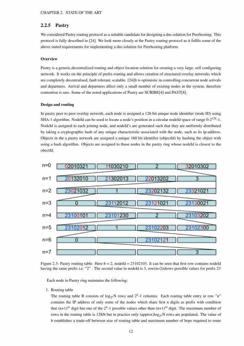
In pastry peer to peer overlay network, each node is assigned a 128-bit unique node identifier (node ID) usingSHA-1 algorithm. NodeId can be used to locate a node’s position in a circular nodeId space of range 0-2128-1.NodeId is assigned to each joining node, and nodeId’s are generated such that they are uniformly distributedby taking a cryptographic hash of any unique characteristic associated with the node, such as its ip-address.Objects in the a pastry network are assigned a unique 160 bit identifier (objectId) by hashing the object withusing a hash algorithm. Objects are assigned to those nodes in the pastry ring whose nodeId is closest to theobectId.
Figure 2.3: Pastry routing table. Here b = 2, nodeId = 23102103. It can be seen that first row contains nodeIdhaving the same prefix i.e. ”2” . The second value in nodeId is 3, row(n=2)shows possible values for prefix 23
Each node in Pastry ring maintains the following:
1. Routing tableThe routing table R consists of log2bN rows and 2b-1 columns. Each routing table entry at row ”n”contains the IP address of only some of the nodes which share first n digits as prefix with conditionthat (n+1)th digit has one of the 2b-1 possible values other than (n+1)th digit. The maximum number ofrows in the routing table is 128/b but in practice only (approx)log2bN rows are populated. The value ofb establishes a trade-off between size of routing table and maximum number of hops required to route
12

CHAPTER 2. STATE OF THE ART
between a pair of hops. With a value of b equalling four, the average number of hops is approximatelyequal to five.
2. Neighbourhood setThe Neighbourhood set (M) contains nodeIds and IP addresses of |M| closest nodes to current node inrespect to proximity metric. This information is used to improve routing locality properties and is notused for routing normally.
3. Leaf setThe Leaf set L is the set of nodes comprising of |L|/2 nodes with numerically lower NodeIds and |L|/2nodes with numerically higher nodeIds relative to the nodeId of the current node. The Leaf set informa-tion is used for message routing and it contains the set of nodes of size L, which are numerically closestto current nodeId, with half nodes having smaller nodesId’s and half with greater nodeIds than the currentnode.
Operation
Any node in the pastry ring can initiate a message towards a target node using a key. With a message and a keyas a input , the node sends the message to other pastry nodes on the network, which then delivers the messageto the node whose nodeId is numerically closest to key, among all the live Pastry nodes. This process continuesuntil the message is delivered to the numerically closest node. The maximum number of routing steps possiblebefore the message reaches the target node is O (log2b N), where b is a constant and N is the number of nodesin the pastry nodes.
Pastry advantages
Pastry aims to minimize the message travel distance considering network locality, using any given scalar prox-imity metric, for example the number of IP routing hops. Each Pastry regularly transmits keep-alive messagesto inform the neighbouring nodes of their status. This mechanism notifies application on live nodes of nodefailures, new nodes and recovered nodes in the nodeId space. Since node ID’s are randomly assigned, the prob-ability of adjacent nodeId’s being allocated in a wide geographic area is extremely high. This property is usefuland ensures that the message reaches nodes with numerically closest nodeId in accordance with the proxim-ity metric which is often completely different from the physical metrics. This property is also advantageousas messages are spread across diverse geographic region which enables better load distribution and improvessystem robustness against failure of part of network.
2.3 DDNS
2.3.1 Overview
[6]DDNS is a peer to peer domain name system which stores and retrieves resource records using DHash(Chord based distributed hash table).The system inherits Chords fault tolerance and load balancing propertiesand reduces administrative problems with the current DNS.
2.3.2 Operation
Each node in the system selects a n-bit identifier randomly generated using the hash of some fixed informationsuch as IP address. The identifiers (nodes) are arranged in a circular ring called the name space. The objects areassigned lookup keys which is generated by taking the hash of the object with some random salt. Each node ina chord ring is responsible for storing objects with keys closer to its nodeId i.e in-between the the current nodeand its previous node. Figure 2.4 shows a chord ring showing responsibility of each node in the ring. [25]The
13

CHAPTER 2. STATE OF THE ART
Figure 2.4: [23] Chord ring showing the responsibility of keys
routing is performed by using a finger table algorithm. The algorithm allows the nodes to memorise locationsof other nodes in the peer network which reduces the number of traversals required to resolve a query. In achord ring the maximum cost of reaching the desired destination node responsible for the queried key is log(n)where n is the size of the chord network.
2.3.3 Advantages
The DDNS offers the following benefits over existing DNS system.
1. DNS is a administered hierarchical system, hence requires certain level of expertise to administer. WhereasDDNS is a peer based DNS and separates service from its authority. The content owner and its Data cansimply be entered into the chord storage ring without worrying about the ISPs to be on-line all the time.
2. It offers a better approach to load balancing as the concept of the hierarchical managed DNS is eliminatedand the dns information is replicated on multiple nodes selected randomly.
3. It offers better resistance to denial of service attacks as the data is replicated on nodes connected to thechord ring. Taking out a few nodes from the system will not affect availability of data. Also to cater toincreased demand, resource record sets can be replicated to more nodes.
4. It is based on DHash which offers improved robustness and load balancing by allocating keys to nodesevenly through consistent hashing.
5. The data is cached by nodes along the lookup path which increases the probability of spreading data oneach node by only log m transmissions where m is the size of chord ring.
6. Dhash moves the data automatically so that the data is replicated across a fixed number of nodes ina pseudo-random fashion. This makes system resistant to denial of service attacks and improves faulttolerance.
14

CHAPTER 2. STATE OF THE ART
2.3.4 Challenges
DDNS system was designed by Russ Cox et. al [6], they demonstrated that DDNS system is faced withsome challenges, which is significant in context of the functionality required in the peerhosting model. Thechallenges have been discussed below.
1. The time taken to resolve a dns query in DDNS is higher than the conventional DNS. This is because ina chord ring , a message requires O(logb n) remote procedural calls per lookup where b= 2. This equalsto 20 RPCs in a network consisting of million nodes. The latency in traversing 10-20 RPC is unrealisticfor a domain name system.
2. The client needs to be updated each time a new functionality is to be offered by the system which isinfeasible and problematic.
3. The system depends on coupling of administrative hierarchy with the service structure. Clients are a partof the chord ring. Thus there is no incentive for clients to serve DNS for other people servers.
2.4 CoDoNS
2.4.1 Overview
[21]CoDoNS is a peer based cooperative domain name system which provides high performance using Beehivereplication layer to reduce the lookup latency and increase query throughput. CoDoNS is based on Pastryrouting protocol which works on the principle of prefix matching for searching objects on the CoDoNS network.The beehive replication layer has been explained in detail in the following paragraphs.
2.4.2 Beehive
[20]Beehive is a high performance peer to peer replication layer. It uses structured replication and enables O(1)search latencies on the overlay, meaning that the maximum cost of finding a solution can be one hop (for afraction of queries). Beehive considers replication and caching as a fundamental problem. The caching opti-mization is expressed taking into account the trade-off between the cost of replication and the resulting systemperformance. This analytical formulation enables Beehive to predict expected behaviour of the system.
Beehive improves performance by replicating objects dynamically on the overlay based on factors such ascontent demand, demand patterns etc. It performs mathematical computation to calculate the cost of replicationand compares it with the actual benefit of replication in reducing the lookup time.
Operation
Beehive works on the principle of replicating objects at some established level in the DHT circular space. Levelof replication signifies the number of nodes on which the object is replicated. For example, objects whose levelis 0, has to be distributed at all nodes across the system, similarly objects whose level is ”i” are replicated onall nodes having at least ”i” matching prefixes. Beehive uses various replication strategies through which itdecides a replication level for each object. Figure 2.5 shows the effect of replication in the system.
Beehive employs several inexpensive algorithms through which it computes the replication level for eachnode dynamically, the key parameter used by such algorithms being the popularity of the object. It does so withthe aim of providing a constant cost of finding an object in the system while reducing administrative control toensure availability.
15

CHAPTER 2. STATE OF THE ART
Figure 2.5: Replication level in Beehive system.[20] ”A query for finding object with objectId ”0121” takesthree steps from node Q to node E (Home Node).” By replicating the object at level two (D and F), the latencyis reduced.
Beehive uses the following models for computing the level of replication:-
1. Monitoring protocolMonitoring protocol estimates properties of query distribution and popularity of objects by collecting,monitoring and aggregating the locally available data. Monitoring is performed by individual nodes bymeasuring the object access frequency and then aggregating them with other nodes statistics after regularintervals. Each node gather aggregate data from other nodes which are one level higher in routing table,which results in trickling of aggregates to the lowest level node, ultimately reaching the home node. Thehome node computes the total aggregate and spreads this information to all the replicas in the network.
2. Analytical modelEach Beehive node invokes the analytical model after every ”analysis interval” to find out the level ofreplication for its objects. Analytical model consists of closed form optimal solutions through which anode finds the appropriate level of replication for each object it stores. The results of the monitoringprotocol i.e. the estimates are fed as a input to the analytical model. The analytical model captures spacetime trade-off while incurring a minimum bandwidth and storage overhead cost by replicating objectsacross several nodes.
3. Replication protocolReplication protocol replicates objects to a level specified by the analytical model. Each node is respon-sible for deciding the local replication factor according to which it replicates the object on the adjacentnodes (nodes which are one hop away).
16

CHAPTER 2. STATE OF THE ART
Characteristics
Beehive adds to the resilience and scalability of structured overlays by providing the following critical charac-teristics necessary to support performance demanding applications/infrastructures.
1. AdaptabilityBeehive quickly recognizes and respond to large-scale increase in popularity of objects occurring due toflash crowds and denial of service attacks. Beehive detects change in popularity of objects and adjust theextent of replication accordingly.
2. Quick updatesUpdates in Beehive percolate using a mechanism called Proactive replication. Beehive nodes notifyother nodes of updates by distributing copies of object. Unlike legacy DNS mechanism, it does not useTTL parameter for caching and ensures consistency of modifiable objects using proactive propagation ofupdates.
3. High PerformanceBeehive guarantees content availability and consistent lookup performance while requiring minimumeffort, memory, network bandwidth and load.
2.4.3 Operation
CoDoNS consists of distributed nodes that can self organise to form a network. It associates the domain to anode based on the similarity of objectId to the globally unique node identifier, such a node is called the homenode. In a CoDoNS system, the home node is responsible for storing, maintaining and replicating the resourcerecord on the network. In case of failure of home node, the next closest node takes up the responsibility andbecomes the home node of the domain. CoDoNS prevents data loss by replicating the resource records onnodes (servers) adjacent to the home node in the CoDoNS network.
CoDoNS system uses Pastry routing protocol for routing messages. A brief explanation of it is as follows.A client sends a query(in Legacy DNS format) to a local CoDoNS server. The server looks up for the cachetable and responds if finds any entry, else it directs the request on the internal CoDoNS network. The requestterminates at either the home node or the intermediate node having cached copy. The node answers the requestby sending the data to the nearest CoDoNS server which then replies to the client. In case the server is not ableto find the resource record in the system, the home node fetches the record from the legacy DNS and sends theresult back to the requesting server.
2.4.4 Characteristics
CoDoNS relies on cooperating peer caches which change dynamically according to the popularity of an object.It offers following unique characteristics:
1. DOS resilienceCoDoNS is highly scalable as it responds favourably to denial of service attacks by dynamically changingthe replication level of an object to distribute the load among multiple peers.
2. High performanceUsing the analytical model of Beehive, CoDoNS servers can answer queries even in a single hop. Theperformance of such a service is way better than the legacy DNS and DDNS as the number of hopsrequired to answer a query is greatly reduced.
17

CHAPTER 2. STATE OF THE ART
Figure 2.6: CoDoNS System: Clients sending request to local CoDoNS server. The server obtains RR from thehome node/ intermediate node or from legacy DNS. The home node sends back reply through the server backto the client.
3. Lower latencyCoDoNS has lower latencies than the conventional DDNS (20 RPCs in a network of million nodes)andlegacy DNS which typically needs 2 RPCs. Pastry takes O(logbn) remote procedural calls per lookupwhere b= 16. This equals to only 5 RPCs in a network consisting of million nodes.
4. Quick updatesUpdates in the CoDoNS are spread in relatively short time, nodes can be updated at any given time. Intraditional DNS updates become relevant after the TTL of the data has expired. Thus, CoDoNS enablesdynamic relocation of services, particularly in response to emergencies.
2.4.5 Challenges
Some of the challenges and ad faced by CoDoNS systems are:-
1. The peer based systems require that the results of all potential queries be anticipated and stored in advancewhich is not always possible. In the conventional DNS, some systems such as Akamai use custom DNSresponses for better load balancing and to route the clients to nearby servers reducing latency.
2. [23] The CoDoNS system has unrealistic memory requirements on each node.
2.4.6 Relevance
The system is relevant in solving the DNS problem in context of peerhosting model due to the following factors:
1. No change is required on the resolver or the client side. The system integrates well with the current DNSclients and no change in the client-side resolver libraries is required.
2. Domain names can be explicitly added and securely managed by the owners. It can also acquire mappingsfrom the legacy DNS.
18

CHAPTER 2. STATE OF THE ART
3. It achieves high lookup performance using Beehive, an analytically driven proactive caching layer. [20].Beehive anticipates demand and replicates DNS data automatically throughout the network.
4. The peer based architecture of the CoDoNS has decoupled the name-space management from the servicehierarchy in the network.
5. Domain name records in the system are self validating and tamper proof. All the clients(nodes) on thenetwork can answer the query authoritatively without the need to refer to the authoritative server.
6. It counters the possibility of delay by allowing direct caching. CoDoNS allows name owners to directlyinsert, modify, update and delete their records in their own administrative domain.
111
19

Chapter 3
System requirements and architecture
In this chapter we will discuss the underlined principle, key requirements and a system design for Peerhostingdns. The system is designed to create a robust peer based dns solution for Peerhosting platform.
3.1 Peerhosting
3.1.1 Overview
Current web hosting environments require Web Hosting Providers (WHPs) to maintain fixed resources suchbandwidth much greater than required to account for sudden unexpected demand peaks. This is absolutelyessential to adhere to the contracted QOS. This model is expensive and wasteful as WHPs are required to makeprovision for additional resources even when there is no need. It should be noted that the term peer has beenused interchangeably with node as both of them refer to participant nodes in the dns network. Figure 3.1 showsa technical diagram of Peerhosting platform customised to interface with its dns network.
Figure 3.1: Peerhosting Architecture
20

CHAPTER 3. SYSTEM REQUIREMENTS AND ARCHITECTURE
Peerhosting provides a hosting infrastructure which aims to improve QOS offered by HPs while reducingcost to their clients. Peerhosting is an open, global and self balancing cluster of WHP web servers belonging todifferent organisations. WHPs safely collaborate to deliver the content through content sharing and distribution.
Peerhosting comprise of a centralised market model (Broker service) which enables real time trade amongstpartner HPs. Broker service allows HPs to purchase credits enabling them to transfer their content to other HPsto cater to increased demand. The Broker is also responsible for redirecting the clients to new content location(HPs). This service is completely transparent to the clients and hence there is no need to change client resolvers.
Peerhosting integrates the hosting capacity of individual web hosting providers through the use of:
• Content distribution system
• Client Redirection
• Execution of monitoring services
3.1.2 Stakeholders
The Peerhosting comprise of following four stakeholders:
1. Hosting ProvidersHosting providers are members of Peerhosting infrastructure providing active nodes which host or delivercontent upon the request from the broker.
2. BrokerIt is the key component of Peerhosting infrastructure. It enables trade of hosting capacity between partnerHPs and manages peer based delivery of web content to clients by redirecting them to the appropriateHP.
3. Content ProvidersCustomers of any HP and a members of the market who want to share their content (such as websites,audio, video, virtual machines etc.) on the world wide web.
4. Internet UsersClients who access/consume the content on the world wide web through the use of standard browsers.
3.1.3 Operation
The Peerhosting platform operates as follows:
1. Initially, the content providers register with hosting providers to host their content on the world wideweb. Then content providers register with the Peerhosting infrastructure by purchasing capacity fromthe Peerhosting broker. This capacity is aggregated from the underlying peer network of the Peerhostinginfrastructure and used to host content of the content provider. To host their content, the content providerscan either select HP’s themselves or the selection can be dynamic based on HP nodes offering requiredQOS at the lowest possible expense to the content provider.
2. The content is replicated across the peer network(HPs) to prevent data loss due to node failure. In mostcases virtual machines containing the content and runtime environment are transferred over the networkwhich gets installed automatically on the peer systems(HPs). The HPs hosting this content register withthe broker to activate the monitoring system for accounting resource usage.
21

CHAPTER 3. SYSTEM REQUIREMENTS AND ARCHITECTURE
3. Broker is responsible for providing domain name resolution services. On receiving request for contentpowered by Peerhosting, the broker directs the clients to the appropriate HP which is hosting the content.Broker selects the HPs based on technical and financial factors. This decision is made in real time.
4. The client receives the resolved IP address for the dns query and accesses the content from the resolvednode(HP).
5. The resource utilisation at the HP on Peerhosting infrastructure that served the request is registeredperiodically for billing the content provider.
3.1.4 Challenges
There are a few unsolved problems in the Peerhosting infrastructure though we are primarily concerned withthe domain name resolution service offered by the Broker. Therefore we will focus only on the challenges increating a name service for peerhosting. Some of the apparent drawbacks of the current implementation ofdomain name service provided by Broker in Peerhosting model are:
1. It uses a centralised database server which maps domain names to IP address. Such an implementationis prone to denial of service attacks as it creates becomes central point of failure.
2. A central database is not scalable and would not be able effectively resolve queries for many thousanddomains simultaneously.
3. It would require huge resources to perform computations before selecting the most appropriate node at agiven time for each domain.
4. It co-locates the resources and its management by domain owners which puts additional load on thesystem.
It is worth nothing that the legacy dns system is unsuitable for Peerhosting model due to the followingreasons:-
1. The content location is varying dynamically and hence it would not be able to support fast update prop-agation
2. Requires dedicated resources and its management by domain owners.
3. Extensive dependence on caching which is unsuitable as computations are performed in real time.
3.2 DNS Requirements
The system under consideration is domain name resolution service for Peerhosting platform. The key attributesof the desired solution are that the system should be scalable, fault tolerant and offer optimal query resolutiontime while providing dynamically managed, distributed and decentralised domain service to the Peerhostingplatform. On a dns request, the system should be capable of making decisions in real time to select the mostappropriate HP to redirect the client. This selection is performed using performance data fed by dns peer nodesin Peerhosting platform. A key point to be observed is that the Peerhosting dns network is different from thePeerhosting content network consisting of HP’s. The dns peer network takes the responsibility of resolvingdomain names from the broker and make a decision on the HP to be served to a client request based on thestatistical performance data from all HP’s in possession of content for a unique content provider.
22

CHAPTER 3. SYSTEM REQUIREMENTS AND ARCHITECTURE
3.2.1 Primary Goals
The primary goals of the system are as follows:-
• It should be based on the peer to peer based technology for efficient load balancing to improve robustnessagainst dos attacks. Each hosting provider (HP) contributes a node to the dns peer network to ensure acontinuous resource pool of sufficient bandwidth, CPU and storage. Similar to the Peerhosting model,the resource contribution by individual HP’s will be logged and billed to the content provider.
• It should provide domain name resolution service to users without having the need to modify the existingclient resolvers. The system should be transparent to the user.
• Only designated nodes (HPs) and content providers should be given authoritative access to their resourcerecords in the system.
• The system should prevent insertion by unauthorised nodes and prevent duplication of resource recordsfor a unique domain by blocking new inserts for an already inserted domain.
• The Hosting provider servers should be able to insert their individual performance statistics regularly forthe domains they serve to the nodes which are responsible for storing corresponding dns resource recordsthrough a designated gateway node.
• Each dns peer node is independently capable of performing calculations using the received data to returnthe most appropriate result (IP address of most appropriate HP to serve the content). It reduces centralisedcomputation by allowing embarrassingly parallel computations to be performed on individual nodes. Aresource record set (RRset) is a list of records containing different IP addresses for a particular domain.The nodes receive a domain name as a request and it replies by selecting the most appropriate IP addressamong the RRset after performing relevant computations.
• Only designated nodes are capable of accepting dns queries from clients.
• Only designated nodes are capable of accepting statistical information from Peerhosting HPs or from theBroker to prevent unauthorised access
• The system provides load balancing mechanisms in two places. First by distribution of dns resolutionresponsibility on multiple nodes through replication of objects on the peer network. Second, resolvingthe domain to different IP-addresses based on the performance statistics returned by the domain servers.
• Evaluation of the system to analyse its feasibility in view of low query latency requirements.
3.2.2 Secondary Goals
The secondary goals of the system are as follows:-
• Replication and proactive caching mechanisms could be implemented to reduce the number of steps toresolve a query while reducing query latency.
• Ensure a constant replication level for a resource record. For example, in the case of node failure respon-sibility of failed node should be transferred to other available nodes dynamically.
• The system should be fault tolerant and should function normally providing consistent uninterruptedservice to users.
• The system attains a maximum latency target of 1 second for any dns query resolution. Ideal latencyrequirements are of the scale of 100-500ms.
• The system must provide high availability and must be robust against high churn.
23

CHAPTER 3. SYSTEM REQUIREMENTS AND ARCHITECTURE
3.2.3 Stretch Goal
• The system decouples ownership authority from the responsibility of resolving dns requests by placingin additional security mechanisms such as public key cryptography mechanisms to sign RRsets.
• The system implements dns protocol and interfaces with the legacy dns resolvers to receive dns resolutionrequest.
• An efficient scheduling algorithm which selects hosting servers(IP-address) as an answer to the dnsrequest.
• Monitoring Engine: Monitoring Engine is an essential component of the system as it provides a mech-anism which calculates and aggregates the resources offered by all participants (dns peers) to host adomain name for a content provider.
• To establish trust among content providers about system integrity, security mechanisms needs to bedevised. One such mechanism is the independence given to the content providers to select trusted peersto resolve resource records for their domain.
3.3 Proposed System Design
In this section we will discuss our application design in view of stated requirements. We use the underlyingarchitecture of the past [8] in addition to additional components such as replication strategies, caching policies,performance monitoring system. We have created a performance engine on each peer through which a peerperforms calculation on the statistical data it receives from the HP servers serving the content to select the mostappropriate IP address. Also we have introduced a host of new features which are discussed below, in view ofthe specific requirements of the Peerhosting network.
We will discuss the proposed dns design with detailed explanations of various system components.
3.3.1 System Overview
Peerhosting dns comprises of geographically distributed nodes with self organisation capabilities to create apeer to peer network. We assume that each participating entity (HP) on the Peerhosting network will dedicatea server with pre-agreed resources to the Peerhosting dns network to create a very large pool of resources forstoring dns resource records (RRset) and resolving the stored domains. Content providers are automaticallyregistered in the Peerhosting dns system upon their registration with the Broker. The proposed dns systemprovides query resolution services to clients using dns protocol and thus existing resolvers do not require anychange.
Peerhosting dns separates query resolution from name space management. Unlike legacy dns system,Peerhosting dns is based on a flat structure where each domain name is a separate entity which is stored ondistinct peer nodes. The dns resource records in the system are inserted by the broker in agreement with thecontent provider. To host their dns resource records, the content provider may select the peers manually ordelegate this responsibility to the broker. In both cases, a resource record set (RRset) is prepared by the Brokerwhich consists of IP address of all HPs who are responsible for hosting content for a domain name. A hash ofRRSset domain is taken using the hash algorithm, which forms the objectId. Using objectId, RRset is insertedin the Peerhosting dns and its responsibility delegated to a node (Home Node). The home node is the nodewhose nodeId is closest to the ObjectId in the system. The home node is responsible for managing replicationand ensures constant replication factor for the domain. Figure 3.3 shows a client directing a dns request tothe Broker. The Broker performs two key functions of inserting the dns records and forwarding the query
24

CHAPTER 3. SYSTEM REQUIREMENTS AND ARCHITECTURE
Figure 3.2: Peerhosting DNS Architecture
to the Peerhosting dns system. An Insert Performance Gateway is also shown to be receiving performanceinformation from HPs in Peerhosting platform.
3.3.2 System Architecture and components
This section describes the system design. It also explains various components and mechanisms in the Peerhost-ing dns.The system consists of the following main components:
1. Insert Gateway NodeInsert Gateway Node is a node on the Peerhosting DNS network which is authorised to interact with theBroker to insert resource records in the system.
2. Insert Performance NodeInsert Performance Gateway Node is a node on the Peerhosting DNS network which is authorised tointeract with the HPs to insert performance information for a resource record (domain) in the domainshome node.
3. Query Gateway NodeQuery Gateway Node is a node on the Peerhosting DNS network which is authorised to interact withclients to resolve domains hosted with Peerhosting platform.
25

CHAPTER 3. SYSTEM REQUIREMENTS AND ARCHITECTURE
Insert Gateway Node
Figure 3.3: Insert dns resource record with replication factor of four
Insert Gateway node on the Peerhosting dns system interfaces with the Broker to insert resource records.Insert Gateway node receives resource records from the Broker and computes a 160 bit hash for each entry(resource record). The computed hash of an object is referred to as the objectId and it is used to locate theappropriate home node of the resource record. A domain object is delegated to a live node whose nodeId isclosest to the ObjectId, this node is referred as Home Node. When the Broker inserts the domain object withnodeId as the key, the object is routed to the Home Node. The home node either accepts or denies responsibilityfor a domain, for either operation it sends a acknowledgement message to the Broker. Once Home Node acceptsresponsibility of a domain, it is the responsibility of the home node to resolve the domain and manage domain’sobject replication. An insert operation is performed in the following sequence:
• Step 1Broker initiates an insert operation.
• Step 2Gateway node computes ObjectId(key) for the domain using a hash algorithm . It then prepares a insertmessage before transmitting it on the dns system.
• Step 3The insert message is delivered to the home node. The home node stores the domain object in local storeand becomes the authoritative node for the domain.
• Step 4Home node reads the domain’s replication factor(k) and initiates an insert operation on k-1 nodes. Thesenodes are selected from the leaf set of the home node. All the selected nodes either accept or deny thedomain object responsibility and conform their action to the home node.
• Step 5Home node returns a message to the Insert Gateway confirming the insert operation with a log of suc-cessful and failed inserts. The log contains a list of NodeIds on which the object is replicated.
26

CHAPTER 3. SYSTEM REQUIREMENTS AND ARCHITECTURE
Insert Performance Gateway
Figure 3.4: Insert performance statistics from HPs in Peerhosting DNS
Insert Performance gateway interfaces between the Broker and Hosting provider servers(HP servers) on thePeerhosting content system. It receives and inserts the performance statistical information from the HP serversin the dns peer network. It also ensures that the performance information reaches only the authorized homenode by sending this data directly to the home node. If it does not receive confirmation message from any ofthe node, it re-tries to insert the data after fixed time intervals before it reports the problem to the Broker. Aninsert operation is performed in the following sequence:
• Step 1HP Servers initiate an insert operation by sending the performance data to the Performance Gatewaynode.
• Step 2Gateway node computes ObjectId for the domain and locates the home node of the domain.
• Step 3The Gateway node sends an insert message to the home node.
27

CHAPTER 3. SYSTEM REQUIREMENTS AND ARCHITECTURE
• Step 4The home node locates the resource record for the given domain to retrieve the list of replica nodes. Itthen sends an insert message containing the performance data directly to the replica nodes.
• Step 5All the replica nodes send the confirmation message back to the Home node which then conforms it tothe Performance Gateway node.
Query Gateway
Figure 3.5: DNS query resolution operation
Query gateway is one of the most critical components in the system. Multiple query gateway nodes arecreated in diverse geographic locations to improve system robustness against failure of a single gateway dueto bandwidth and throughput constraints. This is to distribute the query resolution load while reducing lookuptimes. To further improve the QOS, a Broker may multicast a query to multiple Query Gateways and sends areply to the client with the result from the Gateway which responds the earliest. For each query it calculatesthe hash of the domain (ObjectId) and initiates a lookup message, using the ObjectId as the destination. Thedestination node upon receiving the query message, sends the resolved IP address to the Query Gateway whichthen it to the Broker.
The dns query resolution involves the following steps:
• Step 1Clients initiate a dns query directed towards the Peerhosting Broker. The Peerhosting Broker redirectsthe query to single of multiple Query Gateway nodes.
• Step 2A Query Gateway node then computes the objectId and generates a query for that objectId. The querytraverses multiple hops before it reaches its destination. In the given example, it takes three hops beforethe query(objectId 3101) reaches its destination(3100) as the nodeId of the source node was completelydifferent from the objectId.
• Step 3Query is received by the destination node, which has the resource record for the queried domain. Thedestination node resolves the query by accessing the persistent storage and retrieves the appropriate IPfor the queried domain.
28

CHAPTER 3. SYSTEM REQUIREMENTS AND ARCHITECTURE
• Step 4Target node then sends the resolved query back to the Query Gateway node.
• Step 5Query Gateway node returns the resolved IP address to the Broker.
3.3.3 Introduction to Past
[8]Past is a large, scalable, self organising, persistent storage application built on top of pastry. It is essentiallya peer network connected to the internet where each peer contributes its memory, bandwidth and persistentstorage to create a very large common pool of resources.
Usage of Pastry
Past uses pastry protocol for routing messages between a pair of nodes. Therefore we provide a brief overviewof pastry protocol and its use in Peerhosting DNS. Pastry is a highly scalable, fault resilient and self organisingsecond generation peer to peer routing algorithm. It is a multi-hop routing protocol in which the number ofhops to find an object is O(log(N)) in the worst case. Pastry network ensures network locality and minimisesdistance traversed by a message between any two peers. Upon node initialisation, each participating node isallocated a unique 128 bit identifier (nodeId). The nodeId is assigned randomly which ensures uniform nodeprobability in the network space. A heuristic ensures that among all the live nodes in a node’s routing table, themessage is routed to a node whose objectId is closest to the originating node in respect to the proximity metric.Each node selects the next hop by selecting the node with closest matching prefix (longer prefix match by onedigit) to the objectId from all the entries in the routing table which stores the information about the immediateneighbouring nodes in the nodeId space. This mechanism is unable to produce globally shortest routes butsimulations show that the average distance travelled by a message is only 50 percent greater than the actualdistance between source and destination[24].
Node addition
Here we briefly talk about the procedure using which nodes join the peer dns network and what happens whennew nodes join.
When a new node joins a network, it connects to any bootstrap node which allocates this node a uniquenodeId. To initialise its routing table, leaf set and neighbourhood set, the node contacts a nearby node A andasks it to forward a special message to the destination node X. This message is routed to any node Z whosenodeId is numerically closest to X2. X fetches the neighbourhood set from A, leaf set from Z and constructsthe routing table by obtaining the ith row of routing table along route from A to Z.
The other affect of a new node joining the network is that its nodeId may be closer to an ObjectId thanthe existing nodeIds on which an object is already stored by the home node. This creates an imbalance in thenetwork and has to be corrected to ensure successful dns resolutions while maintaing a constant replicationfactor. To correct this imbalance the home node redistributes the object responsibility by revoking the objectfrom old node and storing it on the new node. This is how home node ensures that a object is replicated on onlythe k closest nodes with nodeIds closest to the objectId.
Node failure
Here we will briefly talk about the procedure by which other nodes in the peer dns network are informed ofpossible node failures.
29

CHAPTER 3. SYSTEM REQUIREMENTS AND ARCHITECTURE
Usually, all the nodes in Pastry dns network are made aware of their immediate neighbouring nodes byperiodic exchange of keep-alive messages (beacons). These beacons are sent to all nodes in the node leaf set.Often a set of neighbouring peers share the same leaflet nodes thus when a node disappears, there is no keepalive beacon from that node and this node is then removed from the leaf sets of all nodes. Also the nodesperiodically share their leaflet information and this expedites the whole process of removing dead nodes.
3.3.4 Object Identifier Generation
In the current system, we use a hash table (SHA-1) to generate a 160 bit unique objectId (key) for any domainobject before inserting the object in the dns peer network. Node selection can either be manual or automaticbased on the content providers requirements. In case of automatic assignment objectId is used as a key in select-ing a home node(HN) to delegate responsibility of hosting and resolving a domain name in the peer network.But such approach does not provide transparency in the system about the delegation of home node as objectIdsare computed as a hash of the domain name. The objective is that the content providers are given the option toselect the authoritative Home Node responsible for resolving their domain name based on parameters such astrusted HP’s, their QOS history, available bandwidth resources, their geographic location and reputation. .
In the Peerhosting dns system it is also crucial to instil a sense of trust, security and confidence in thePeerhosting platform. This can be achieved if content providers are allowed to select a home node trusted bythem. It will assure content providers that there content is being managed by a known node trusted by them.For this purpose we propose to develop an system through which objectIds can be customised in a way whichallows manual selection of home node. This can be achieved by generating objectId with value extremelyclose to the desired nodeId so that the domain name’s responsibility is automatically transferred to the desiredpeer. However, if the content provider requires that the dns RRset be replicated across the network on multiplepeers for better services, then the home node will decide the replica peers locally. Thus content providerswill only have limited control in distributing objects on the peer network ensuring fair sharing of resourcewhile preventing excessive load on well known peers. Selection of Home Node peer by content provider andautomatic selection of other peers for replica distribution will ensure fair utilisation of resources on all peerswhile providing fair gains to all the participants.
3.3.5 Storage Load Balancing and Replication
In any content storage system, there is a need to ensure fair storage utilisation and global even distribution ofobjects. Therefore we have used the Past mechanism for ensuring better load distribution and maintaining aconstant replication factor in the peer system. The replication factor k can be defined either by the Broker inagreement with the content provider or it can be dynamically selected based on the demand of the object. Fordynamic selection of the replication factor, the possibility of using Beehive replication layer can be looked into.In case of manual selection, the replication factor is specified during the insert operation. When an object isinserted in the dns system with object replication factor as k, the administrative dns node in the peer systemreplicates the dns object among k-1 leaf set nodes with closest nodeIds for the objectId. It is also importantthat the desired replication factor is achieved at all times by the administrative dns node even if the number ofclosest nodes in the leaf set is less than k. In case a selected leaf set node is unable to store a replica as directedby a home node. The home node selects the next closest node (k+1) from the leaf set using the same algorithmas used earlier. This mechanism is called replica diversion.
30

CHAPTER 3. SYSTEM REQUIREMENTS AND ARCHITECTURE
Conditions for replica diversion
In this section we will discuss the conditions for initiating and controlling replica diversion which are following:
1. When an insert operation is performed with a replication factor k, the insert messages reaches the nodewith the closest nodeId to the objectId in terms of scalar proximity metric. This node becomes theauthoritative node A and stores the object. If the authoritative node A is able to find k-1 available nodesfor storing the object from its leaf set then there is no need for initiating replica diversion. All thecontacted leaf set nodes store the object and return a conformation message to the authoritative node.
2. In case one of the authoritative leaf set node B is unable to store the object. In that case B selects a nodeC from its leaf set with nodeId closest to the objectId and stores the object on that node while creatinga pointer entry for redirecting any query message to C. B also creates a pointer entry on another node Dfrom its leaf set having k+1th closest nodeId with the objectId. D ensures availability of content on Ceven in case of failure of B.
Replica diversion is an important characteristic as it provides a mechanism for local storage space balancingand enables graceful degradation of the system as it reaches maximum storage limit. However this mechanismhas following disadvantages:
1. Overhead in an insert operation for each replica diversion is two RPC’s. And an additional entry has tobe created at both D and B both pointing to C.
2. Query overhead increases by one hop only when a query request is received by B. If a query request isreceived by any other node holding the object, the query latency is normal.
3.3.6 Storage Mechanism
Each node consists of two local object stores, one of which is persistent and the other non persistent (storesobject in local program memory). The storage capacity of the Persistent store is set to 20 mega bytes eventhough it can be input as an argument as well. Persistent object store is called resource record store whilethe non persistent object store is called performance store. These stores are accessed by access objects whoseprime function is to manage and implement synchronisation. We implement the performance store as a nonpersistent memory as nodes act on data for each insert to conclude a new serving HP as the answer and thusthere is no need to maintain old data for a very long time.
Performance object store
As the name suggests, the performance store is used exclusively for storing the statistical performance informa-tion about the serving HPs. Data type of a performance store object consists of a domain name, correspondingsystem IP(IP of serving HP), system load at the serving HP, data instance (used for version control of per-formance data). Once a node receives fresh performance information from a serving HP (system IP)for aparticular domain, the node flushes previously held data. For example, if a node receives performance data for”www.google.com” domain from a serving HP at IP address (12.1.23.4) with performance instance of 14, thenode will remove all previous performance data for ”www.google.com” domain for IP 12.1.23.4. This is doneto prevent the memory store from growing too big and to reduce object store lookup time.
Resource record object store
Resource record store is used for storing the complete resource record sets. Data type of resource record objectconsists of a domain name, an answer field and two lists, one containing IP addresses and the other null. Thefirst list is optional and stores a list of IP addresses which serve this domain permanently. Other list stores IPaddresses (serving HPs) which are added dynamically based on the output of the Performance Engine.
31

CHAPTER 3. SYSTEM REQUIREMENTS AND ARCHITECTURE
3.3.7 Caching
Caching is an important tool in reducing the client fetch latencies (proportional to number of hops traversedin underlying pastry network) and in improving the query throughput of the system by load distribution on thenodes along the query path. However, we have a system in which the IP address of HPs (resolved dns queries)returned by the nodes change based on intermediate / metadata (performance data) after fixed time intervals.Therefore in such a system caching is not a viable option unless the refresh rate of performance data is severalhours. In the Peerhosting content hosting system the expected churn is high, new nodes join frequently and theolder ones discarded. And thus it is expected that the home node receives fresh performance data along withnew node information once or twice an hour or may be more frequently. Therefore as of now we have disabledcaching in our system.
3.3.8 Performance Engine
In the legacy dns system the resolution of domain names is done to a single or multiple dedicated static systemsresponsible for hosting content of a particular content provider. In such mechanism the responsibility of hostingthe content is delegated or controlled directly by the content provider itself. Thus the content providers remainstatic or rarely change. Whereas Peerhosting content distribution system is based on a peer network whichworks by aggregating, allocating and delegating the resources contributed by individual nodes (HPs). In thissystem, individual peers (HPs) can pull out of the Peerhosting platform if they run out of available resources.This coupled with genuine node failures could lead to a extremely high churn in the system. Due to the highchurn the HPs responsible for hosting the content for a domain may change very rapidly in time. The contentis re-located on new nodes based on content providers HP preference, system load and available resources at apeer node, content demand, geographical location of HP’s and other network conditions.
It shall be observed that in Peerhosting the content is hosted by multiple HP’s as a single peer may not beable to cater to demand of all the clients. Therefore, selection of the appropriate peer(HP) among the multi-ple HPs by the dns client becomes a critical task to achieve even load distribution, fair resource sharing andimproved availability of content. To create a stable system and improve the content availability we create aPerformance Engine (PE) on each node in Peerhosting DNS. The Performance Engine analyses and calculatesthe load factor on each node responsible for distribution of the content for a particular domain before resolvingthe dns query to an appropriate HP. All the HP’s serving content for a domain must broadcast their currentsystem information such as system load, available memory, available storage, bandwidth consumption to the’Performance Gateway’ node in the dns peer system. The ’Performance Gateway’ node then locates the homenode for a domain and transfers the performance information to it. One apparent disadvantage of this system isthat the HP have to broadcast their system performance to unknown hosts which is a potential security threat.One possible way of countering this disadvantage is by encrypting the content at the the originating node anddecrypted at the Home node of the domain in the dns peer system. There is still a problem of applying a privatekey pair mechanism in this setup.
The performance data is received by the home node which broadcasts this data to all the replica nodes re-sponsible for resolving dns queries for this domain. The raw data is broadcast with the objective of allowing thenodes to perform embarrassingly parallel computations while reducing system load on a single HP. It should benoted that each node is independent and performs computations to reach to independent conclusions. When anode receives new performance data it activates the PE with performance data as inputs. The PE then performsanalysis to select the most appropriate node(IP address) to be resolved for a dns query for a fixed time interval(time interval is greater than the frequency of receiving updates from HPs serving content). At the moment,the performance engine performs selection based only on the system load parameter though there is scope foradding in more parameters.
32

CHAPTER 3. SYSTEM REQUIREMENTS AND ARCHITECTURE
There can be an argument that performing calculation before answering each query may not be a feasibleoption as it may impact the overall system performance by increasing the query delay significantly. To counterthis, we have designed the peer nodes such that each node initiates the Performance Engine only when itreceives a fresh update of performance information and not before answering each query. The execution ofPerformance Engine is a non blocking operation so the system is available and resolving queries even when itis running.
33

Chapter 4
Implementation
In this chapter, we will discuss the libraries and the models used for development of the Peerhosting dns. Userscenarios will be explained in this chapter for better understanding of the system.
4.1 Language and environment
The ideal target operating system for supporting our implementation of Peerhosting DNS is Debian based Linuxeven though its implementation is platform independent as it executes on Java Platform (JRE6 SDK). All theprograms have also been tested on JRE 1.7.0-icedtea verison which is an open source implementation of Java.Peerhosting DNS has been tested on Ubuntu Linux OS, windows XP and Fedeora 8 machines. It should run wellon most other operating systems which have a rightly configured Java environment. Insert Performance clientswhich monitor and report average CPU load may not work correctly on some Windows based systems as thelibrary used does not ensure accurate system performance on all Windows platforms. Netbeans IDE version 6.5was used during implementation and testing. As the development involved a distributed environment, initiallythe system was tested on a single machine with all nodes being created on a single JVM. Later the system wastested on a local area network and Planetlabs environment.
4.2 System Implementation
System implementation is based on design requirements presented in the previous chapter. Focus of implemen-tation is to get a feature complete working prototype of the proposed system and thus the proposed design issimply taken as a reference point.
The System is built using the iterative software approach with greater focus on scalability, fault toleranceand performance. The following features have been implemented in the first version of the software:
• Pastry network with ability to deliver messages based prefix routing.
• Insert dns resource records mechanism.
• Insert average system load from hosting providers through a Gateway to home node.
• Performance Engine to select the most appropriate HP to serve to a dns request.
• Query resolution mechanism.
• Mechanism to monitor and transfer the HP system load to the Input Performance Gateway.
• Mechanism to generate dns queries.
34

CHAPTER 4. IMPLEMENTATION
Peerhosting dns servers are layered on top of [7]Freepastry library version 2.1 which is the most stable ver-sion of freepastry. Freepastry libraries and key API’s have been discussed in section 4.2.3 extensively. EachPeerhosting dns peer (daemon) implements dns resolver which is event driven and non blocking.
4.2.1 Continuations
Throughout the system, continuations have been used to enable the possibility of non-blocking operations. Acontinuation is similar to a call-back and a listener in Java and it is used to handle network latency and othertypes of Input Output that may block or take a significant amount of time. It is specifically useful in insert andlookup queries as the program will not be blocked, allowing it to initiate multiple requests simultaneously. Sim-ilar functionality can be achieved using a lot of threads with synchronisation and thread locking mechanisms.But this would increase the system complexity and may result in possible system degradation. The followingcode illustrates a continuation command.
p u b l i c i n t e r f a c e C o n t i n u a t i o n{
/∗∗∗ Thi s method g e t s c a l l e d when t h e r e q u e s t e d r e s u l t g e t s a v a i l a b l e .∗∗ @param r e s u l t = t h e r e s u l t o b j e c t r e c e i v e d f o r t h e r e q u e s t made .∗ /
p u b l i c vo id r e c e i v e R e s u l t ( O b j e c t r e s u l t ){
/ / code t o e x e c u t e u s i n g t h e r e s u l t} ;/∗∗∗ Thi s method g e t s c a l l e d when an e x c e p t i o n o c c u r s∗ Due t o t h e r e q u e s t made .∗∗ @param r e s u l t = t h e e x c e p t i o n which o c c u r s .∗ /
p u b l i c vo id r e c e i v e E x c e p t i o n ( E x c e p t i o n r e s u l t ){
/ / code f o r h a n d l i n g t h e e x c e p t i o n} ;
}
4.2.2 Environment
Freepastry provides a class called ’Environment’ which initialises a new node after reading pastry routingprotocol parameters such as leaf set size, maintenance frequencies, number of handles stored per routing table,maximum size of a message from a file named ’freepastry.params’. These parameters can be stated explicitlyby either altering the freepastry.params file or by creating a new ’.params’ file. A new node is required to createan environment to initialise its routing table. Some of the key features of Environment class which have beenused in the system are:
• LoggingEnvironment provides a simple standardised logging mechanism through which system logs are gener-ated for debugging and monitoring purposes. We have used this class for generating logs on individualnodes used for debugging purposes.
35

CHAPTER 4. IMPLEMENTATION
• ParametersParameters are necessary to initialise the program. Parameters can either be provided as arguments orbe entered in a params file as default value. To initialise the node we read the local IP, local bindport,bootstrap IP , bootstrap port parameters as arguments and read routing protocol information from theparams file in the default package.
• SelectorManagerSelector manager is a single non daemon thread which manages timer events and network input output.Selector manager is used for managing multiple threads for improved thread synchronisation. It alsoreduces complexity of implementing synchronisation manually.
• TimeSourceTimeSource is an alternate library for measuring time on each node. It functions similar to ”Sys-tem.currentTimeMillis()” and provides a virtual clock in Free Pastrys event simulator. Another benefit ofusing this library is that the system is not dependent on correct configuration of NTP servers. Thus thislibrary has been used for testing system performance by measuring time difference between operationrequest and operation response.
4.2.3 Usage of Pastry
The system has been developed largely using the Pastry Api’s with major modifications in its code base forimplementing the extra functionality to fulfil the design requirements. It should be mentioned that even thoughthe proposed design suggests the use of UDP as the underlying network layer for communication, the currentnetwork layer implementation is based on use of TCP/IP sockets as provided by the Freepastry library. UDPmessages are only used by nodes to exchange keep alive messages to maintain their leaf sets . The futureversions would support dns protocol which uses UDP as its network layer. This change will make the systemmore robust while improving query throughput. We now discuss some of the APIs that have been used forimplementing key features:
• nodeId= pastryInit(credentials, application)This is used to create a new environment through which a node can either join an existing ring or start itsown ring. If no credentials are entered the node starts a new ring else we need to provide the bootstrapIP address for the current node to join an existing ring. This API also generates and allocates a uniquenodeId to the new node using a random nodeId generator algorithm. The node object is passed as anargument to the application which specifies the node behaviour on various events.
• route (msg, key) This is used to route the given message to the node whose nodeId is closest to the key.Key is represented by the objectId which is generated a hash of the domain name.
• deliver(msg, key) This message is called when the message is received by the destination node (nodeIdclosest to the ObjectId). Several types of messages can be received by a node and each type of messagerequires distinct operations to be performed. A brief explanation of each message is provided below:
– InsertMessageWhen a node receives this message, it initiates a store operation to store the dns resource record inthe persistent store.
– InsertPerformanceMessageWhen a node receives this message, it initiates the Performance Engine to calculate the most appro-priate node for the given domain. It then associates the output from the Performance Engine withthe dns resource record available in the persistent storage.
36

CHAPTER 4. IMPLEMENTATION
– LookupMessageOn receiving a Lookup message, the node looks for the objectId (key) in its persistent storage,retrieves the corresponding object and then responds with the object.
– LookupHandlesMessageOn receiving a lookuphandlesMesssage, a node looks up in the local storage for the correspondingobject and then locates all other nodes responsible for storing this object. It then prepares a list ofall the nodeIds before replying to the source with this list.
• forward(msg, key, nextId)This method is called by a intermediate pastry node before it passes the message to the next node towardsthe destination. This method can be used to trace the object path or to change the contents of message.This could also be used to count the number of hops before a query reaches the destination node.
• newLeafs(leafSet)This method is called when a change in leaf set of a node is observed. Through this method the appli-cation(Home node) is informed of any node failures in the leaf set. This is used to ensure a constantreplication factor of an object. For example, if a node on which object had been replicated goes down, anew replica node can be selected for the object.
• objectId= Insert(object name, owner credentials, replication factor ,object)This method generates a 160 bit unique objectIdId for the object name by parsing its name, ownercredentials and random salt through the SHA-1 hashing algorithm. Before the file is inserted, the objectIdis checked for collisions to prevent multiple insertions with the same objectId. This objectId is then usedfor inserting the object on multiple peers depending on the replication factor of the object.
• file= Lookup(object name)This method computes the SHA-1 hash of the object name to construct an objectId for the domain name.Using the objectId a lookup operation is performed to retrieve the resolved IP address of the domainname from any replica node(out of possible k replicas).
4.2.4 Resource record selection
Resource records are selected on the basis of performance data inserted by the HP servers in the dynamically.The resource records are selected on each performance data insertion only, thereby ensuring fast query resolvingtimes. Currently the performance engine implements a simplistic algorithm which compares the system loadof all the serving HPs for a unique domain and finds the HP with the lowest system load. Whenever a targetnode receives a performance insert operation, it runs the performance engine which outputs the IP address ofthe most appropriate HP serving that domain. This value is then inserted in the answer field of the resourcerecord set of the corresponding domain name.
4.3 System Components
In Peerhosting dns each peer is assigned a distinct role with different responsibilities. Every Peerhosting dnspeer creates an environment and implements a stand-alone daemon running on each node which is accessi-ble via TCP/IP requests from the master daemon. The daemon is event driven and is implemented as a nonblocking master process with multiple slave processes. Slave processes may either be blocking or non-blockingdepending on the type of the request received. For example, in case of an insert request by the remote clientor an insert gateway, the slave process is blocking whereas for query requests from remote clients or peers theslave process is non-blocking.
37
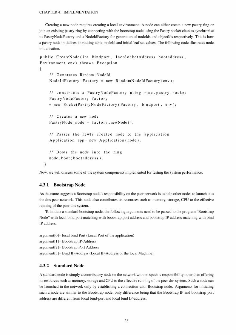
CHAPTER 4. IMPLEMENTATION
Creating a new node requires creating a local environment. A node can either create a new pastry ring orjoin an existing pastry ring by connecting with the bootstrap node using the Pastry socket class to synchroniseits PastryNodeFactory and a NodeIdFactory for generation of nodeIds and objectIds respectively. This is howa pastry node initialises its routing table, nodeId and initial leaf set values. The following code illustrates nodeinitialisation.
p u b l i c Crea teNode ( i n t b i n d p o r t , I n e t S o c k e t A d d r e s s b o o t a d d r e s s ,Envi ronment env ) th row s E x c e p t i o n{
/ / G e n e r a t e s Random NodeIdNode IdFac to ry F a c t o r y = new RandomNodeIdFactory ( env ) ;
/ / c o n s t r u c t s a P a s t r y N o d e F a c t o r y u s i n g r i c e . p a s t r y . s o c k e tP a s t r y N o d e F a c t o r y f a c t o r y= new S o c k e t P a s t r y N o d e F a c t o r y ( F a c t o r y , b i n d p o r t , env ) ;
/ / C r e a t e s a new nodePas t ryNode node = f a c t o r y . newNode ( ) ;
/ / P a s s e s t h e newly c r e a t e d node t o t h e a p p l i c a t i o nA p p l i c a t i o n app= new A p p l i c a t i o n ( node ) ;
/ / Boots t h e node i n t o t h e r i n gnode . boo t ( b o o t a d d r e s s ) ;
}
Now, we will discuss some of the system components implemented for testing the system performance.
4.3.1 Bootstrap Node
As the name suggests a Bootstrap node’s responsibility on the peer network is to help other nodes to launch intothe dns peer network. This node also contributes its resources such as memory, storage, CPU to the effectiverunning of the peer dns system.
To initiate a standard bootstrap node, the following arguments need to be passed to the program ”BootstrapNode” with local bind port matching with bootstrap port address and bootstrap IP address matching with bindIP address.
argument[0]= local bind Port (Local Port of the application)argument[1]= Bootstrap IP-Addressargument[2]= Bootstrap Port Addressargument[3]= Bind IP-Address (Local IP-Address of the local Machine)
4.3.2 Standard Node
A standard node is simply a contributory node on the network with no specific responsibility other than offeringits resources such as memory, storage and CPU to the effective running of the peer dns system. Such a node canbe launched in the network only by establishing a connection with Bootstrap node. Arguments for initiatingsuch a node are similar to the Bootstrap node, only difference being that the Bootstrap IP and bootstrap portaddress are different from local bind-port and local bind IP-address.
38

CHAPTER 4. IMPLEMENTATION
argument[0]= local bind Port (Local Port for the application)argument[1]= Bootstrap IP-Addressargument[2]= Bootstrap Port Addressargument[3]= Bind IP-Address (IP-Address of the local Machine)
4.3.3 Insert Gateway
Insert Gateway peer is implemented as a non-blocking ServerSocket thread listening on a pre-defined porton the standard node. The ServerSocket thread is listening for insert requests from the Peerhosting Broker.The ServerSocket opens a non blocking new thread for each request which then passes an insert request tothe most appropriate neighbouring node from the routing table (prefix matching) by opening a TCP/IP socket.The message hops from node to node until the destination is reached using prefix routing. The target nodeinitiates a blocking call on the node’s local storage to store the resource record. The following code explainsthe implementation of insert continuation command.
/ / C o n t e n t o b j e c tf i n a l P a s t C o n t e n t myContent = new MyPas tConten t ( id , domainName ,
ipAddres s , i n s t a n c e , p e r f o r m a n c e ) ;
/ / i n s e r t s an myContent o b j e c tpas tApp . i n s e r t ( myContent , new C o n t i n u a t i o n <Boolean [ ] , Excep t ion >(){
/ / t h e r e s u l t i s an Array o f Boolean f o r each i n s e r tp u b l i c vo id r e c e i v e R e s u l t ( Boolean [ ] r e s u l t s ){
i n t n u m S u c c e s s f u l S t o r e s = 0 ;f o r ( i n t c t r = 0 ; c t r < r e s u l t s . l e n g t h ; c t r ++){
i f ( r e s u l t s [ c t r ] . b o o l e a n V a l u e ( ) )n u m S u c c e s s f u l S t o r e s ++;
}l ong newtime=env . ge tT imeSource ( ) . c u r r e n t T i m e M i l l i s ( ) ;
/ / measu res t ime t a k e n f o r an i n s e r t o p e r a t i o nlong t i m e t a k e n =newtime−t ime ;
}
/ / P r i n t s t h e r e s u l t o b j e c t r e c e i v e d .p u b l i c vo id r e c e i v e E x c e p t i o n ( E x c e p t i o n r e s u l t ){
System . o u t . p r i n t l n ( ” E r r o r s t o r i n g ”+ r e s u l t ) ;}
} ) ;
To launch an Insert Gateway node on the dns peer network, the gateway node must connect with the boot-strap node using bootstrap IP and port address. Only one extra argument needs to be passed to ”InsertGate-way.jar” to launch this node into the peer dns network which is the local port address at which the server islistening for insert requests. The arguments which need to be passed are mentioned below:
39

CHAPTER 4. IMPLEMENTATION
argument[0]= local bind Port (Local Port of the application)argument[1]= Bootstrap IP-Addressargument[2]= Bootstrap Port Addressargument[3]= Bind IP-Address (IP-Address of the local Machine)argument[4]= ServerSocket Port (Local Port at which the server is listening for ’Insert Data’)
4.3.4 Insert Performance Gateway
For every Insert Performance request this node fetches the nodeHandles of all the peers who are in possessionof resource record object for the domain whose performance value is to be inserted. It then opens a direct socketconnection with each peer and feeds the latest data directly to the target nodes. The cost of this operation isone step. The insert operation method of Insert Performance Gateway is similar to the Insert Gateway node,difference being the type of objects passed in the insert operation and the messages are transmitted directly tothe target nodes. The list of arguments to launch an Insert Performance Node is as follows:
argument[0]= local bind Port (Local Port of the application)argument[1]= Bootstrap IP-Addressargument[2]= Bootstrap Port Addressargument[3]= Bind IP-Address (IP-Address of the local Machine)argument[4]= ServerSocket Port (Local Port at which the server is listening for ’Insert Performance Data’)
4.3.5 Query Gateway
Query Gateway peer is implemented as a non-blocking ServerSocket thread listening on a pre-defined port onthe standard node. The ServerSocket thread is listening for insert requests from the Peerhosting Broker. TheServerSocket opens a non blocking new thread for each request which then passes a lookup message to thenext neighbouring node from the routing table by opening a TCP/IP socket. The message hops from node tonode until the message reaches its destination. The target node accesses the resource record store to fetch the’answer’ value for the given domain name which is then returned directly to the source node (Query GatewayNode). The following code explains the implementation of lookup continuation command.
pas tApp . lookup ( lookupKey , new C o n t i n u a t i o n <P a s t C o n t e n t , Excep t ion >() {p u b l i c vo id r e c e i v e R e s u l t ( P a s t C o n t e n t r e s u l t ){
MyPas tConten t c o n t e n t =( MyPas tConten t ) r e s u l t ;/ / Reso lved IP Address f o r t h e domain
S t r i n g i p a d d r e s s [ ] = c o n t e n t . g e t I p a d d r e s s ( ) ;
}
p u b l i c vo id r e c e i v e E x c e p t i o n ( E x c e p t i o n r e s u l t ) {System . o u t . p r i n t l n ( ” E r r o r l o o k i n g up ”+ lookupKey ) ;r e s u l t . p r i n t S t a c k T r a c e ( ) ;
}} ) ;
To launch a Query Gateway node on the dns peer network, the gateway node must connect with the boot-strap node using bootstrap IP and port address. An extra argument needs to be passed mentioning the port tocreate an external ServerSocket to launch this node into the peer dns network. The arguments which need to bepassed are mentioned below.
40
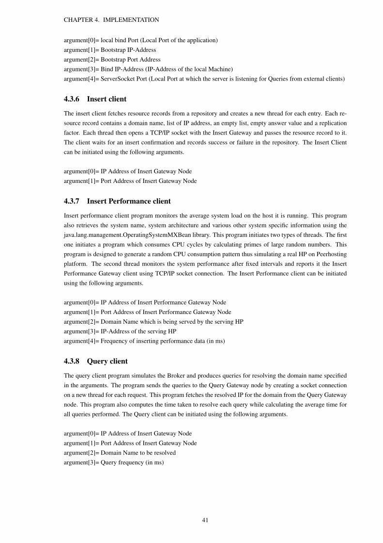
CHAPTER 4. IMPLEMENTATION
argument[0]= local bind Port (Local Port of the application)argument[1]= Bootstrap IP-Addressargument[2]= Bootstrap Port Addressargument[3]= Bind IP-Address (IP-Address of the local Machine)argument[4]= ServerSocket Port (Local Port at which the server is listening for Queries from external clients)
4.3.6 Insert client
The insert client fetches resource records from a repository and creates a new thread for each entry. Each re-source record contains a domain name, list of IP address, an empty list, empty answer value and a replicationfactor. Each thread then opens a TCP/IP socket with the Insert Gateway and passes the resource record to it.The client waits for an insert confirmation and records success or failure in the repository. The Insert Clientcan be initiated using the following arguments.
argument[0]= IP Address of Insert Gateway Nodeargument[1]= Port Address of Insert Gateway Node
4.3.7 Insert Performance client
Insert performance client program monitors the average system load on the host it is running. This programalso retrieves the system name, system architecture and various other system specific information using thejava.lang.management.OperatingSystemMXBean library. This program initiates two types of threads. The firstone initiates a program which consumes CPU cycles by calculating primes of large random numbers. Thisprogram is designed to generate a random CPU consumption pattern thus simulating a real HP on Peerhostingplatform. The second thread monitors the system performance after fixed intervals and reports it the InsertPerformance Gateway client using TCP/IP socket connection. The Insert Performance client can be initiatedusing the following arguments.
argument[0]= IP Address of Insert Performance Gateway Nodeargument[1]= Port Address of Insert Performance Gateway Nodeargument[2]= Domain Name which is being served by the serving HPargument[3]= IP-Address of the serving HPargument[4]= Frequency of inserting performance data (in ms)
4.3.8 Query client
The query client program simulates the Broker and produces queries for resolving the domain name specifiedin the arguments. The program sends the queries to the Query Gateway node by creating a socket connectionon a new thread for each request. This program fetches the resolved IP for the domain from the Query Gatewaynode. This program also computes the time taken to resolve each query while calculating the average time forall queries performed. The Query client can be initiated using the following arguments.
argument[0]= IP Address of Insert Gateway Nodeargument[1]= Port Address of Insert Gateway Nodeargument[2]= Domain Name to be resolvedargument[3]= Query frequency (in ms)
41

Chapter 5
Evaluation
5.1 Introduction to evaluation
Evaluation is an integral part of this project, and was declared as a key goal in the design section. The frequenttask of storing, computing and resolving the domain name with the most appropriate serving HP system isimportant. Also thus system should be robust against node failures and perform well on a much larger scale.The design of Peerhosting DNS minimises reliance on single nodes by distributing various responsibilities tomultiple nodes located in diverse geographic locations.
On a global network such as the Internet, the network conditions and resources available at different nodesare hugely varying with time. Thus it increases the performance uncertainty and makes the system susceptibleto arbitrary failures due to failed nodes. The other possible effects could be system performance degradationdue to high network latency due to network clogging thereby resulting in slow access to some nodes on thenetwork.
This section describes the experimental methods that we use to determine the performance of PeerhostingDNS. We then investigate and evaluate the performance achieved while comparing it with desired performance.
5.2 Evaluation system configuration
For the purpose of experimentation of Peerhosting DNS system, all the tests were carried out in two environ-ments with completely different network, hardware and software configurations. This is done so with an aimto establish feasibility of Peerhosting DNS network in different environments and network configurations. Itmust be observed that the tests were conducted in networks containing nodes ranging from 10-500. The twoenvironments are:
1. Local area network (10-500 nodes)
2. PlanetLabs (10-30 nodes)
The configuration of both of these environments has been described as follows:
5.2.1 software configuration
Local area network
All the test/evaluation machines (nodes) in the LAN network were configured with an installation of WindowsXP Professional service Pack 3 and were updated with all security patches. Various university authorised thirdparty software was installed on each machine, though it was ensured that none of it was active while testing the
42

CHAPTER 5. EVALUATION
system.To ensure that idle tasks were not running, various tasks such as Windows Indexing service and windowsrestore facility were disabled. However, these services do enable automatically from time to time, there impacton system performance is not significant as it is not likely to affect network connections in any way.
PlanetLab
All the test/evaluation machines on the PlanetLab network were configured with a fresh installation of Fedora8 virtual machine. Since virtual machines are allocated on each node, the underlying physical resources andnetwork bandwidth is shared among many users and processes. The virtual machine allocated does not runany application software other than the Peerhosting DNS software. Java Runtime version 1.7.0-icedtea (opensource) was installed on all the test machines for execution of Peerhosting DNS application.
5.2.2 Hardware configuration
Local area network
The local area network nodes featured the following hardware components:
• Intel Core2Duo processor, clocked at 2.4 GHz
• 4GB DDR2 800MHz RAM
• 1 TByte
PlanetLab
The PlanetLab nodes featured the following components
• Intel Xeon 30x0 2.4Ghz (Mcore/Core2Duo)
• 4GB DDR2 RAM
• 1 TByte
5.2.3 Network Configuration
Local area network
It must also be observed that all the nodes in this environment were connected through the same local areanetwork and nodes had access to Internet. However, the Internet connectivity was not used while testing thesystem. At the time of testing, the local area network traffic was observed to be ideal and churn was negligible.
PlanetLab
[5]PlanetLab is a global research network which supports development and testing of new network servicessuch as peer to peer systems, network mapping services and distributed storage etc. PlanetLab consists of 1120nodes located across 510 distinct geographical locations.
It must also be observed that all the nodes in this environment had Internet connectivity and were notconnected by a local network. All the communication between these nodes occurred over the internet onTCP/IP connections. This is a relatively unstable network in comparison with local area network as each nodein PlanetLab shares its physical and network resources among many users and processes. Nodes often godown for maintenance purposes and some nodes may not be reachable due to network clogging or other systemfailures. Thus churn is higher than ideal.
43

CHAPTER 5. EVALUATION
5.3 Design of evaluation system
5.3.1 Introduction to design of evaluation system
For testing and evaluating the performance of Peerhosting DNS, programs were customised to add capabilityto measure the performance metric such as the query delay. We perform tests with a view of measuring querylatency as it is the single biggest determinant in establishing the feasibility of our design approach. Freepastryoffers libraries which allow simulation of a large network containing thousands of nodes in single JVM. It isalso possible to change network topologies using the simulator but it has two drawbacks. Firstly, the simulatordoes not account for message loss, varying bandwidth and varying latency. Secondly, simulator does notsimulate other factors that a comprehensive simulator such as ns-2 simulates. Due to the above drawbacks andthe inability of the simulator to recreate a volatile network with varying latencies, measuring query delay usinga simulator would not yield accurate results.
5.3.2 Evaluation of Peerhosting DNS
To evaluate the Peerhosting DNS system, changes were made in Insert Gateway and Query Gateway programto reflect the delay in performing each request received from the corresponding client programs. The storagemechanism on the Query Gateway nodes was disabled thus preventing local storage and retrieval of requestedDNS records. New functionality was added to allow Gateway programs to receive requests from clients onspecific predefined ports. It should be observed that the delay is calculated as the time taken by the program toperform a complete operation as observed by the Gateway node. Insert DNS client and query client simulateBroker while insert performance client simulate serving HPs in the Peerhosting infrastructure. Clients arecapable of generating query resolution requests, insert DNS record, insert performance statistic requests atvarying rates (requests/second).
5.4 Implementation of evaluation system
The evaluation system comprises of basic test infrastructure and specialised infrastructure for both LAN andPlanetLab testing.
5.4.1 Basic Test Infrastructure
The basic test infrastructure remains same for both LAN and PlanetLab testing. To run the tests, the evaluationsystem executes ’Insert DNS client’ to insert DNS resource records in the system. For each test, the number ofdomains inserted equals (2
√N+3) where N is the total number of nodes in the network. The first 2*N domains
inserted had a replication factor of 10 to maximise the DNS resource density on nodes to better account fortime taken to locate resource records. The other three domain values were inserted with different replicationfactors of zero, five and ten, which were then queried to observe delay. For each test suite different domainnames were queried to change the query pattern in the network.
5.4.2 Query Latency
Query delay is the most significant factor in establishing the feasibility of our design approach. Therefore wemeasure the query delay at the Query Gateway nodes by querying domain names in peer network containing100-500 nodes.
LAN
To setup the evaluation infrastructure, all the jar files namely ”QueryGateway.jar”, ”InsertGateway.jar, ”Insert-GatewayPerformance.jar”, ”InsertDnsClient.jar”, ”InsertPerformanceClient.jar,” and ”QueryClient.jar” were
44

CHAPTER 5. EVALUATION
copied manually on each host. Fresh JRE was installed on all the machines and the required jar files wereexecuted using appropriate arguments. In case of LAN, query delay test infrastructure consists of four pairs ofquery clients and Query Gateways out of which query delay performance is observed on two pairs while theother two pairs (unobserved) are used to generate network traffic. The two unobserved pairs query random do-mains to generate random traffic patterns in the system while the two observed pairs query domains as directedby the user. The clients for both observed and unobserved pairs generate queries at the rate of 100 queries persecond. Tests are performed for network sizes of 100 nodes, 250 nodes and 500 nodes. It should be observedthat only 10 physical machines were used for actual testing and multiple nodes were simulated on each machineto increase the network size. For each domain, delay was observed on two Query Gateways (pairs). The first50 values from both the gateways were taken, summed and averaged to determine mean and median score.
PlanetLab
To setup the evaluation infrastructure on PlanetLab, 311 nodes with sufficient free bandwidth were selected andadded to the slice ”tcd4” provided by the principle investigator (PI). Then a private public key pair was gener-ated and public key added to all the nodes in the slice. Private Key was used to authenticate the user and accessthe remote nodes on the slice. A script was written which installed openJDK on all the host machines. All the jarfiles namely ”QueryGateway.jar”, ”InsertGateway.jar,”InsertGatewayPerformance.jar”, ”InsertDnsClient.jar”,”InsertPerformanceClient.jar” and ”QueryClient.jar” were copied manually one by one in the home folder ofeach node. Fresh JRE was installed on all the machines and the required jar files were executed using appro-priate arguments.
In case of PlanetLab testing, query delay test infrastructure consists of three pairs of query clients and QueryGateways out of which query delay performance is observed using two pairs while the other pair (unobserved)is used to generate network traffic. The unobserved pair queries random domains to generate random trafficpattern in the system while the two observed pairs query domains as directed by the user. The clients for bothobserved and unobserved pairs generate queries at the rate of single query per second. Tests are performed fornetwork size of 10 and 35 nodes. It should be observed that for PlanetLab testing different physical machineswere used for each experiment. The values were then added and averaged to determine mean and medianscores.
45

CHAPTER 5. EVALUATION
5.5 Evaluation results
In this section we discuss and elaborate our findings for various tests performed. It should be noted that theterms query delay, lookup latency and query latency have been used interchangeably and they refer to the timetaken by a Query Gateway node to resolve a domain name.
5.5.1 LAN test with no replication
Introduction to this test
The objective of this test to establish and compare the query delay statistics observed by a Query Gatewaywhile querying a domain name which has not been replicated at all. The delay is observed for a peer networkconsisting of 100, 250 and 500 nodes. The test is performed on nodes in a local area network and maximumsteps required to resolve a query should not be greater than 3, 2 and 2 hops for networks containing 500, 250and 100 nodes respectively. We have arrived at the above figures using the formula log2bN where b equals 4and N equals the number of nodes in the pastry network.
Results of this test
The results can be seen in the figure 5.1
Figure 5.1: Query delay observed when replication factor (k) equals zero
Evaluation of Results
The results show degradation in average query delay while increasing network size. Even though, there is agreater query delay difference between network of 100 and 250 nodes than between network of 250 and 500nodes, the actual variation is in range of 70ms which is not insignificant. The results also show that in a networkof 500 nodes, 50 percent of the queries were answered in less than 280ms.
46

CHAPTER 5. EVALUATION
5.5.2 LAN test with five replicas
Introduction to this test
The objective of this test to establish and compare the query delay statistics observed by a Query Gateway whilequerying a domain name which has been replicated at five nodes including the home node. Due to replicationthe maximum steps required to resolve a query should be less than 3, 2 and 2 hops for networks containing500, 250 and 100 nodes respectively. The test has been performed on a LAN therefore the network traffic wasnot bursty and the churn was negligible.
Results of this test
The results can be seen in the figure 5.2
Figure 5.2: Query delay observed when replication factor (k) equals five
Evaluation of Results
The result show that replication of a DNS resource record has a significant impact on query delay times. Thequery delay observed for resolving replicated domains is less than delay observed for domains which werenot replicated at all. This is true for network containing 100, 250 and 500 nodes. A significant difference inaverage delay is observed in case of 100 node network in comparison to 250 and 500 node network.In this testscenario The results for resolving a domain name with some replication follow a similar pattern to the domainresolution for no replication, though with improved query resolution time.
47

CHAPTER 5. EVALUATION
5.5.3 LAN test with ten replicas
Introduction to this test
This test is performed to observe the effect of excessively high replication on query resolution time. Thedomains with a replication factor of 10 are queried by Query clients and the delay is observed at Query Gateway.Due to the excessive replication the maximum steps required to resolve a query should be less than 3, 2 and2 hops for networks containing 500, 250 and 100 nodes respectively. This test has been performed on a LANtherefore the network traffic was not bursty and the churn was negligible.
Results of this test
The results can be seen in the figure 5.3
Figure 5.3: Query delay observed when replication factor (k) equals ten
Evaluation of Results
The results show that the effect of replication is more dominant in small peer to peer networks. The effectreduces rapidly as the network size increases. The delay observed for resolving a resource record with a veryhigh replication factor of 10 is comparable to records which are replicated at only five nodes. It can also beseen that the median is greater than the average delay for all network sizes, which point towards an imbalancein query resolution times for the same domain. This shows that increasing the replication factor can resultin highly varying query delay. This observation is not surprising due to the random routing paths in pastrynetwork.
48

CHAPTER 5. EVALUATION
5.5.4 Delay range comparison
Here we elaborate and compare the results obtained from performing the above tests. Figure 5.4 shows acomparison table showing the query delay range observed in above tests.
Figure 5.4: Query delay comparison observed on local area network
Peer network containing 100 nodes
It can be seen that in a peer network containing hundred nodes, the minimum query latency for domains with noreplication is twice the minimum latency observed for domains with replication level of five or ten even thoughtheir maximum delay is comparable. Excessive replication of object does not have any significant impact onquery delay in a peer network of this size.
Peer network containing 250 nodes
In a peer network containing two hundred fifty nodes, the query delay range remains similar to a networkcontaining 100 nodes albeit with an upward shift in minimum and maximum delay times. The minimumand maximum observed query latencies reduce marginally as we increase the replication factor of the querieddomain. A huge overlap is observed in the delay range across various replication factors even though fiftypercent queries have been resolved in less than 250 ms irrespective of the replication factor.
Peer network containing 500 nodes
The query delay observed in a 500 node network is significantly higher than a network containing 100 or 250nodes for domains which are not replicated at all. This difference is less apparent in case of DNS records whichhave been replicated across multiple domains even though the maximum observed delay is higher than thenetwork containing 100 or 250 nodes. Surprisingly, the minimum query latency in case of objects replicatedacross ten nodes is higher than objects which are replicated across less number of nodes. The query delaymedian for different domains with distinct replication factors of 0, 5 and 10 is consistent and fifty percent ofqueries get resolved in less than 300ms.
49

CHAPTER 5. EVALUATION
5.5.5 PlanetLab test with no replicas
Introduction to this test
This test was conducted with an objective of finding latency metrics in the PlanetLab environment consistingof ten and thirty five nodes. The query latency for a DNS record with replication factor of zero is observed atQuery Gateway program. The maximum steps required to resolve a query should not be greater than two hopsfor both networks containing 10 and 35 nodes. We have arrived at the above figures using the formula log2bN
where b equals 4 and N equals size of network, while adding one hop for the target node to reply to the QueryGateway node.
Results of this test
The results can be seen in figure 5.5
Figure 5.5: Query delay observed when replication factor (k) equals zero on PlanetLab nodes
Evaluation of Results
The results show that the fifty percent of the queries were resolved in less than 400ms and 200ms for networksconsisting of ten nodes and thirty five nodes respectively. According to the calculations performed, queries inboth the network should not take more than two steps in resolving the DNS request. The huge difference inthe observed query latencies underscores the effect of external factors in query resolution times. It is againhighlighted that these networks were created using different node sets.
50

CHAPTER 5. EVALUATION
5.5.6 PlanetLab test with five replicas
Introduction to this test
This test was conducted with an objective of finding latency metrics in the PlanetLab environment consistingof ten and thirty five nodes when the queried domain objects were replicated across five nodes including thehome node. The query delay is observed at the query gateway node. The maximum of two steps are requiredto resolve a query in both networks containing 10 and 35 nodes. We have arrived at the above figures using theformula log2bN where b equals 4 while adding one hop for the target node to reply to the Query Gateway node.
Results of this test
Figure 5.6: Query delay observed when replication factor(k) equals five on PlanetLab nodes
Evaluation of Results
The results show that the fifty percent of the queries were resolved in less than 400ms and 170ms for networksconsisting of ten nodes and thirty five nodes respectively. According to the calculations performed, queries inboth the network should not take more than two steps in resolving the DNS request. The huge difference in theobserved query latencies further underscores the effect of external factors in query resolution times. It is alsohighlighted that these networks were created using different node sets. Also it is observed that in small peernetworks (10-35 nodes), the effect of replication is negligible, and the only advantage of replication would beto increase resource availability albeit at the cost of more management data on the network.
5.5.7 Comparison of delay range
Here we elaborate and compare the results obtained from performing the above tests. Figure 5.7 shows acomparison table showing the query delay range in a PlanetLab setup for object replication factor of zero andfive.
51

CHAPTER 5. EVALUATION
Figure 5.7: comparison
Peer network containing 10 nodes
In a peer network containing ten nodes, the query delay for searching replicated DNS records is similar tosearching non replicated DNS records. The effect of replication is observed is negligible.
Peer network containing 35 nodes
In a peer network containing thirty five nodes, the query delay for searching replicated DNS records is signifi-cantly lower in comparison to searching non replicated DNS records.
5.6 Evaluation conclusion
The results show that the time taken to resolve a domain does not exceed a mark of 550ms in any of the testsperformed. The maximum average time required to resolve a query in a stable peer to peer network consistingof 500 nodes in a local area network setting does not exceed 300ms irrespective of object replication factor.
LAN conservative estimate
Our tests showed average delay without object replication to be no more than 260ms. This figure allows us tobelieve that even if we take a conservative estimate of delay for each hop, it should not greater than 130ms asthe minimum number of steps taken would not be less than two. Computing the number of steps in a very largepastry network using the formula log2bN where b equals 4 and N equals 10,000, we find that the number ofsteps required to resolve a domain name is not greater than five. Based on the above calculation and the derivedresults we approximate the query delay in Peerhosting DNS system containing thousands of nodes. Even if wetake a conservative estimate of the query delay time in a Peerhosting DNS network comprising of ten thousandnodes when objects are not replicated at all, the average query delay would not be greater than 130*5 whichequals 650ms.
LAN actual estimate
We also take an estimate of the average lookup times in a large Peerhosting DNS network consisting of 10,000nodes in accordance with the mean delay observed in a peer network of 500 nodes. Our tests showed averagedelay without object replication to be no more than 260ms. The maximum number of steps to resolve a querycannot be greater than three. Assuming that a query takes three steps to resolve, we come at a figure of 87msfor resolving a query. Now, we account the approximate average query resolution time for a Peerhosting DNSnetwork consisting of ten thousand nodes. As calculated earlier, the maximum steps for resolving a domainin such network would not take more than 5 steps. If we now estimate the average lookup time for traversingfive hops, we arrive at a figure of 433ms. Our approximation of average lookup time is very close to the [21]average latency offered by the current legacy DNS which is equal to 382ms.
52

CHAPTER 5. EVALUATION
PlanetLab performance
Our PlanetLab test results show that the average query delay observed is of range 200ms to 400ms irrespectiveof object replication levels for pastry network comprising of 10 - 35 nodes. The maximum steps for resolvinga query in a network of ten to thirty five nodes is not greater than two and thus the average hop time can becalculated to be in range of 100ms - 200ms. For a network comprising of ten thousand nodes, a maximum offive steps would be need to resolve a domain name. Therefore the average query time can be approximated tobe in range of 500ms to 1000ms. In addition to the approximated results, we believe that PlanetLab tests showa large variation due to varying external factors. Therefore we propose to perform further extensive tests usingPlanetLab infrastructure to produce a better approximation of results which would serve as a foundation forsystem performance on larger networks.
53
Chapter 6
Conclusions
6.1 Introduction
In Chapter 5 we presented the evaluation of Peerhosting dns with respect to the query delay times. We alsopresented an approximation of the Peerhosting system performance for a very large peer network consistingof ten thousand nodes and then compared it with the average query resolution time in the legacy DNS. Inthis chapter we will draw conclusions from the system design and evaluation to explore the suitability of thesolution. We will also discuss some possibilities which would enable to improve system performance andderive a better approximation of system performance.
6.2 Conclusions
We believe that pastry routing protocol has real potential of being used to create a peer to peer dns service espe-cially in view of Peerhosting requirements. Evaluation of proposed solution shows that the computational costat each node is reasonable and it does not impact the query delay significantly. The design has been successfulin eliminating cost of selecting most appropriate answer for a domain request at a given node by separatingquery mechanism from execution of Performance Engine. The design also addresses the requirement of loaddistribution among multiple nodes by replicating objects and broadcasting performance data from serving HPsin Peerhosting content system to the designated replica nodes in peerhosting dns system.
A pastry based dns service is a likely possible solution for Peerhosting in view of the query times observed,as has been shown in Evaluation conclusion in Chapter 5. The results showed that the average query delay ina dns peer system containing five hundred nodes to less than 350ms. An approximation using the observedstatistics was made to conclude that average query delay in a peer network consisting of 10,000 nodes wouldbe in range of 433ms - 650ms in stable networks. We believe that delays of this range are acceptable for a dnssolution and the query delay can be optimised using better system implementation and caching mechanisms fordomains whose HPs are stable and change less frequently.
Overall we find that a peer to peer dns service based on pastry routing protocol is an acceptable solution inview of the average delay latency observed.
54

CHAPTER 6. CONCLUSIONS
6.3 Future work
This section details areas of future work that are related to this dissertation.
6.3.1 Peerhosting integration
Peerhosting dns is designed to be an integral part of the Peerhosting project. In this thesis we designed and eval-uated the feasibility of pastry based dns solution for Peerhosting. In our current implementation we have usedclient programs to simulate Peerhosting behaviour. And now that we have found the solution as a appropriatecandidate we propose integration of our dns implementation with Peerhosting code base in the future.
6.3.2 PlanetLabs testing
The current system was not intended to run on Planetlab infrastructure. As a result, we were able to performlimited Planetlabs testing, therefore we propose to modify the Peerhosting dns code base to suit Planetlab testenvironment. We also propose to test the system thoroughly on PlanetLab infrastructure to obtain realisticresults on larger networks.
6.3.3 DNS protocol
The current implementation does not conform to the dns protocol, and the resource records objects are imple-mentation differently. Nodes communicate using TCP/IP socket connection instead of UDP messages as usedin legacy DNS system. We intend to implement the DNS protocol in the next version of the Peerhosting dns.
6.3.4 Delegation authority
Control over delegation of home node for a domain name by its content provider is an integral requirement ofPeerhosting project. We have proposed a rudimentary system to achieve this functionality. In the future, thisaspect shall be researched further.
6.3.5 Security layer
The current implementation of Peerhosting dns lacks security features as proposed by DNSSEC. Freepastryenables generation of private public key pair for each object to provide some level of control to the objectowner. But clearly this mechanism does not satisfy the needs of Peerhosting project. The control over adomain name is exercised regularly by several HPs hosting a domain to insert their performance statistics inthe dns peer network. Therefore private key needs to be transferred regularly to the new nodes which may leadto authoritative access to dns record by unscrupulous HPs.
6.3.6 Caching layer
Initially, we intended to implement Beehive caching layer as an overlay on Peerhosting dns, but soon it werealised that it would be infeasible to implement any kind of caching mechanism until their is some stabilityin the systems serving a domain. This requires establishment of Broker infrastructure which would determinestable nodes eligible to use benefits of caching layer. This feature is dependent on the Peerhosting Infrastructureand will be investigated based on further development of Peerhosting platform.
55

CHAPTER 6. CONCLUSIONS
6.3.7 Monitoring tools
Tools to manage and monitor the resources offered by individual nodes need to be created. As the Peerhostingdns works on resources contributed by independent HPs there is a need to account and monetise the resourcesoffered by these nodes to enable fair sharing of resources while establishing a sense of trust among HPs in thesystem.
6.4 Lessons learned
This chapter concludes this dissertation. In this chapter we have presented the benefits and limitations of thisapproach and conclude that this approach is suitable to requirements of domain name service for Peerhostingsystem.
56

Bibliography
[1] P. Albitz and C. Liu. DNS and Bind. O’Reilly Media, 2001.
[2] Stephen Barrett. Peerhosting. A request for Comment for Peer Technology for Web Hosting Industry,May 2009.
[3] J. Byers, J. Considine, and M. Mitzenmacher. Simple load balancing for distributed hash tables. Peer-to-
Peer Systems II, pages 80–87, 2003.
[4] M. Castro, P. Druschel, A.M. Kermarrec, and A.I.T. Rowstron. SCRIBE: A large-scale and decen-tralized application-level multicast infrastructure. IEEE Journal on Selected Areas in communications,20(8):1489–1499, 2002.
[5] B. Chun, D. Culler, T. Roscoe, A. Bavier, L. Peterson, M. Wawrzoniak, and M. Bowman. Planetlab:an overlay testbed for broad-coverage services. ACM SIGCOMM Computer Communication Review,33(3):12, 2003.
[6] R. Cox, A. Muthitacharoen, and R. Morris. Serving DNS using a peer-to-peer lookup service. Peer-to-
Peer Systems, pages 155–165, 2002.
[7] P. Druschel, E. Engineer, R. Gil, Y.C. Hu, S. Iyer, A. Ladd, et al. FreePastry. Software available at
http://www. cs. rice. edu/CS/Systems/Pastry/FreePastry.
[8] P. Druschel and A. Rowstron. PAST: A large-scale, persistent peer-to-peer storage utility. In Proc. HotOS
VIII, pages 75–80. Citeseer, 2001.
[9] D. Eastlake. Secure domain name system (dns) dynamic update. draft-ietf-dnssec-update2-00. txt, Trans-
finite Systems Company, 1998.
[10] A. Friedlander, A. Mankin, W.D. Maughan, and S.D. Crocker. DNSSEC: a protocol toward securing theinternet infrastructure. Communications of the ACM, 50(6):50, 2007.
[11] J. Jung, E. Sit, H. Balakrishnan, and R. Morris. DNS Performance and the Effectiveness of Caching.IEEE/ACM Transactions on Networking (TON), 10(5):589–603, 2002.
[12] D. Karger, E. Lehman, T. Leighton, R. Panigrahy, M. Levine, and D. Lewin. Consistent hashing and ran-dom trees: Distributed caching protocols for relieving hot spots on the World Wide Web. In Proceedings
of the twenty-ninth annual ACM symposium on Theory of computing, pages 654–663. ACM, 1997.
[13] A. Kumar, J. Postel, C. Neuman, P. Danzig, and S. Miller. Common DNS implementation errors andsuggested fixes. Technical report, RFC 1536, USC/Information Sciences Institute, 1993.
[14] P. Maymounkov and D. Mazieres. Kademlia: A peer-to-peer information system based on the xor metric.Peer-to-Peer Systems, pages 53–65, 2002.
[15] J. Mirkovic and P. Reiher. A taxonomy of DDoS attack and DDoS defense mechanisms. ACM SIGCOMM
Computer Communication Review, 34(2):39–53, 2004.
57

BIBLIOGRAPHY
[16] P.V. Mockapetris and K.J. Dunlap. Development of the domain name system. ACM SIGCOMM Computer
Communication Review, 25(1):112–122, 1995.
[17] M. Naor and U. Wieder. Novel architectures for P2P applications: the continuous-discrete approach.ACM Transactions on Algorithms (TALG), 3(3):34, 2007.
[18] L.B. Pei. Web caching and zipf-like distributions: Evidence and implications. In INFOCOM, pages126–134. Citeseer, 1998.
[19] CG Plaxton, R. Rajaraman, and AW Richa. Accessing nearby copies of replicated objects in a distributedenvironment. Theory of Computing Systems, 32(3):241–280, 1999.
[20] V. Ramasubramanian and E.G. Sirer. Beehive: Exploiting power law query distributions for O (1) lookupperformance in peer to peer overlays. In Symposium on Networked Systems Design and Implementation,
San Francisco CA. Citeseer, 2004.
[21] V. Ramasubramanian and E.G. Sirer. The design and implementation of a next generation name servicefor the Internet. In Proceedings of the 2004 conference on Applications, technologies, architectures, and
protocols for computer communications, pages 331–342. ACM, 2004.
[22] S. Ratnasamy, P. Francis, M. Handley, R. Karp, and S. Schenker. A scalable content-addressable network.In Proceedings of the 2001 conference on Applications, technologies, architectures, and protocols for
computer communications, page 172. ACM, 2001.
[23] E. Rescorla and N. Resonance. Introduction to Distributed Hash Tables. IAB plenary, IETF, 65.
[24] A. Rowstron and P. Druschel. Pastry: Scalable, distributed object location and routing for large-scale peer-to-peer systems. In IFIP/ACM International Conference on Distributed Systems Platforms (Middleware),volume 11, pages 329–350. Citeseer, 2001.
[25] I. Stoica, R. Morris, D. Karger, M.F. Kaashoek, and H. Balakrishnan. Chord: A scalable peer-to-peerlookup service for internet applications. In Proceedings of the 2001 conference on Applications, tech-
nologies, architectures, and protocols for computer communications, page 160. ACM, 2001.
[26] P. Thurrott. Microsoft suffers another DoS attack, 2001.
[27] PF Tsuchiya. The landmark hierarchy: a new hierarchy for routing in very large networks. In Symposium
proceedings on Communications architectures and protocols, pages 35–42. ACM, 1988.
[28] G. Urdaneta, G. Pierre, and M. van Steen. A Survey of DHT Security Techniques. ACM Computing
Surveys, 2009.
[29] C. Wills and H. Shang. The contribution of DNS lookup costs to web object retrieval. Worcester Poly-
technic Institute Technical Report TR-00-12, 2000.
[30] B.Y. Zhao, J. Kubiatowicz, and A.D. Joseph. Tapestry: An infrastructure for fault-tolerant wide-arealocation and routing. Computer, 74:11–20, 2001.
58