domestic heating by oil: boiler systems - bse sector - bpecbpec.org.uk/downloads/ce29 - domestic...
TRANSCRIPT
Domestic heating by oil:
boiler systems – guidance
for installers and specifiers
CE29
2 Domestic heating by oil: Boiler systems – guidance for installers and specifiers (2008 edition)
Contents
Introduction to best practice 1. 3
Boiler efficiency 1.1 4
Energy consumption and emissions 1.2 4
Environmental impact of oil heating 1.3 5
UK Building Regulations 2. 6
Introduction 2.1 6
General requirements 2.2 6
England and Wales 2.3 8
Scotland 2.4 9
Northern Ireland 12.5 0
Boiler types 13. 1
Condensing boilers 13.1 1
Regular boilers 13.2 2
Combination boilers 13.3 2
Range Cooker boilers 13.4 3
Systems and components 14. 4
Sealed and open-vented systems 14.1 4
Domestic hot water 14.2 5
Solar hot water systems 14.3 7
Upgrading systems 14.4 8
Flue types 14.5 8
Heat emitters 24.6 0
Circulator pumps 24.7 0
Controls 25. 1
Individual controls 25.1 1
Selecting controls 25.2 5
Further control improvements 25.3 6
Central Heating System 6. Specifications (CHeSS) 28
Energy Efficiency 37. 0
Comparing boiler efficiencies 37.1 0
The Standard Assessment Procedure 37.2 1
Energy consumption and running costs 37.3 1
Carbon dioxide emissions 37.4 2
The Boiler Efficiency Database 37.5 3
Saving energy with better controls 37.6 3
System selection: practical issues 38. 5
Which type of boiler is most suitable? 38.1 5
What size boiler is required? 8.2 35
Where will the boiler be positioned? 38.3 6
What will be the flue terminal position 8.4 and arrangement? 37
Where does the condensate drain go? 38.5 7
What are the arrangements for the oil 8.6 tank and oil supply? 38
Are there any special ventilation 8.7 requirements? 38
Will it be an open or sealed system?) 38.8 8
What type of hot water system is most 8.9 suitable? 39
What type and size of heat emitters are 8.10 required? 39
What controls are needed? 48.11 0
Installing central heating systems 49. 1
Competent person requirements 49.1 1
Installing the boiler 49.2 1
Installing the condensate drain pipe 49.3 2
Condensate drain termination 49.4 4
Controls 49.5 7
Oil storage and supply 49.6 8
Water treatment 49.7 9
Commissioning and handover 510. 0
Commissioning 510.1 0
Advising householders 510.2 0
Servicing 510.3 1
Appendix A – Notes to CHeSS 2008 52
Appendix B – Definitions of boiler types 55
Appendix C – Definitions of heating controls 57
Appendix D – Energy efficiency checklist 59
Appendix E – Heating controls: simple explanations for householders 61
References 64
Front cover image courtesy of Titan Environmental Ltd,
part of Kingspan Environmental
Domestic heating by oil: Boiler systems – guidance for installers and specifiers (2008 edition) 3
Home energy use is responsible for over a quarter of UK carbon dioxide (CO2) emissions which contribute to climate change. To help mitigate the effects of climate change, the Energy Saving Trust has a range of technical solutions to help UK housing professionals build to higher levels of energy efficiency.
This guide is designed to help installers, specifiers and purchasers of domestic central heating systems to select the most suitable system for their needs. It gives advice on how to achieve better energy efficiency, lower running costs and reduced CO2 emissions.
This publication is particularly concerned with the encouragement of best practice. While the requirements for satisfying building regulations in various parts of the UK are described, the main purpose is to explain how to achieve better performance through careful choice of systems and practices.
This publication focuses on wet or hydronic central heating systems in which the water is circulated to heat emitters from an oil-fired boiler. For domestic heating the oil is usually kerosene although sometimes gas-oil is used. Bio-fuels are under development to offer alternatives with lower CO2 emissions.
This publication specifically addresses issues concerning the selection of boilers, hot water storage vessels, controls and indeed complete systems. It brings together information on most types of boiler currently available, the systems to which they can be fitted and key points to consider when choosing equipment for a particular installation. It concentrates on the use of condensing boilers since they must be fitted in both new and replacement installations in most cases. More detailed information on the specification, installation, commissioning and use of oil-fired equipment is available from the Oil Firing Technical Association (OFTEC) website at www.oftec.org
How to use this guideThe guide is set out as follows:
Section 2 explains the building regulations for heating and hot water systems in different parts of the UK.
Sections 3, 4 and 5 go into some detail about the range of systems, boilers and controls currently available.
Section 6 reproduces the Central Heating Systems Specifications (CHeSS). These set out specifications for meeting the basic efficiency levels needed to comply with building regulations as well as higher performance levels regarded as current best practice. They can be used as ready-made purchase specifications.
Section 7 focuses on the benefits to be obtained from choosing best practice.
Section 8 covers the practical issues affecting the selection of boilers, systems and controls.
Section 9 is concerned with proper installation, especially with regard to the flues and drains needed for condensing boilers, as well as oil storage and supply issues.
Section 10 offers guidance on commissioning and other related issues such as servicing and information to be provided to customers.
The appendices provide additional notes to the CHeSS specification, together with definitions of different boiler types and controls.
Note: the superscript numbers in brackets in the text refer to documents listed at the end of this guide.
Introduction to best practice1.
4 Domestic heating by oil: Boiler systems – guidance for installers and specifiers (2008 edition)
Introduction to best practice
Boiler efficiency 1.1 The efficiency of the boiler is the main factor in the overall efficiency of a domestic central heating system. This is why minimum standards of efficiency are required by law for most boiler types. UK building regulations require a higher performance than the EU Boiler Efficiency Directive(17) but best practice requires boilers of even higher efficiency to be selected.
In turn, the efficiency of the overall system has a major impact on running costs and the associated CO2 emissions. Boiler efficiency depends upon:
Fuel•Boiler type and design•The load on the boiler due to the weather•Boiler and radiator sizing relative to the design •heat loadSystem controls•Flow and return temperatures•Installation and commissioning•System free from sludge and scale•Regular servicing and maintenance. •
The advances in boiler technology mean that when older boilers are replaced, substantial efficiency improvements can be expected from newer equipment. Manufacturers now design for maximum efficiency consistent with durability. The greatest energy efficiency benefits are obtained from installing condensing boilers. These are always more efficient than non-condensing models. It is now a requirement of the building regulations that newly installed oil-fired boilers should be condensing, with a SEDBUK (Seasonal Efficiency of a Domestic Boiler in the UK) efficiency of 86% or more, unless exceptional circumstances apply (see Section 2.2).
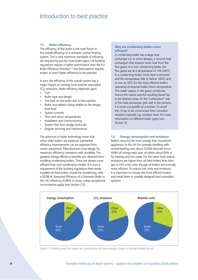
Energy consumption and emissions 1.2 Boilers consume far more energy than household appliances. In the UK the average dwelling with central heating uses about 23,000 kilowatt-hours (kWh) of energy each year, of which about 85% is for heating and hot water. For the same heat output, emissions are higher from oil-fired boilers than from gas or LPG ones, even though oil boilers are normally more efficient. To reduce fuel costs and emissions it is important to choose the most efficient boilers and install them in suitably designed and controlled systems.
Figure 1: Heating and hot water as a proportion of total energy usage in homes heated by oil
Boiler 88%
Boiler 80%
Boiler 70%
Other12%
Energy consumption
Other20%
CO2 emissions
Other30%
Relative costs
Why are condensing boilers more efficient?A condensing boiler has a large heat exchanger (or, in some designs, a second heat exchanger) that extracts more heat from the flue gases. In a non-condensing boiler, the flue gases are at a temperature of 120-200°C. In a condensing boiler, more heat is removed and the temperature falls to below 100°C and as low as 50°C for the most efficient boilers operating at reduced boiler return temperature. The water vapour in the gases condenses (hence the name) and the resulting liquid has to be drained away. As the “combustion” side of the heat exchanger gets wet in the process, it is more susceptible to corrosion. To avoid this, it has to be constructed from corrosion-resistant materials e.g. stainless steel. For more information on different boiler types (see Section 3).
Domestic heating by oil: Boiler systems – guidance for installers and specifiers (2008 edition) 5
Introduction to best practice
Environmental impact of oil heating1.3 Oil relative to other fuelsThe main environmental impact of heating systems is the emission of CO2. When burning oil, CO2 emissions are approximately 37% greater than those from burning natural gas to give an equal amount of heat, and approximately 13% higher than those from LPG (liquefied petroleum gas). However, it is possible to obtain slightly higher efficiencies from oil boilers than from natural gas or LPG boilers, so for the same amount of useful heat output from a boiler the CO2 emissions are approximately 29% and 10% higher.
De-carbonisation of oil for domestic heatingWork is already in progress to establish bio-fuels as a partial or complete replacement for kerosene (the oil used by most domestic oil boilers). Initially, it is intended that liquid bio-fuel and kerosene will be blended in a fixed ratio to bring the CO2 emissions down to a level near that of natural gas. Before the blend can be used, some conversion work will be needed to the burners and other equipment within oil boiler systems. The longer term aim is to enrich the blend in stages by decreasing the proportion of kerosene.
Alternatives to oil heatingAlternatives that may have a lower environmental impact should be considered where practicable. They include:
Wood-burning boilers•Micro-CHP units•Electric heat pumps.•
Micro-CHP, although burning oil or other fuels, produces electricity as a by-product that offsets the carbon burden of central generation. Where heat pumps are considered it should be borne in mind that the relevant efficiency indicator is the seasonal performance factor (i.e., the annual average installed system performance, taking account of annual variation in the British climate) including hot water service as well as space heating. This is not the same as the coefficient of performance measured in standard laboratory tests.
Where an oil heating system is chosen, fuel consumption and carbon emissions can be reduced by combining it with solar water heating (see Section 4.3).
6 Domestic heating by oil: Boiler systems – guidance for installers and specifiers (2008 edition)
UK Building Regulations2.
Introduction2.1 This section outlines the minimum standards for heating efficiency as set out in the building regulations. The remainder of this guide then concentrates on best practice – a higher standard.
The building regulations set a legal requirement to make ‘reasonable provision . . . for the conservation of fuel and power in dwellings’. However, the approved guidance makes clear that there may well be alternative ways of achieving compliance, and different strategies can be adopted provided it can be shown they are at least as good as those already accepted as reasonable provision.
There are different building regulations* in England and Wales, Scotland, and Northern Ireland. They restrict the types of heating system that may be installed in both new and existing dwellings. The different regulations in each country are summarised in later sections, but for details reference should always be made to the official documents(18,19,20).
For new dwellings the general approach is to demonstrate compliance by showing that the carbon emissions are below a given threshold for a particular dwelling. There are also minimum SEDBUK efficiencies that apply to oil boilers. The efficiency of the particular make and model of boiler installed is used in the calculation of carbon emissions for individual dwellings.
For existing dwellings there are minimum requirements for boiler efficiency, hot water storage vessels, pipe insulation, controls, and commissioning that apply when heating systems are replaced or modified.
In England, Wales and Northern Ireland detailed guidance on the minimum requirements for heating and hot water systems is given in the Domestic Heating Compliance Guide(21). This guide was prepared with support from industry and offers specific information on how to achieve compliance. In Scotland the detailed guidance is incorporated in Technical Standards handbooks(19).
* This guide outlines the relevant building regulations in England, Wales, Scotland and Northern Ireland. Regulations that apply in Jersey, Guernsey and the Isle of Man are broadly similar but it is essential to refer to official guidance.
Other parts of the regulations deal with the related issues of the safety of heating installations and with fuel storage. They are Part J (England and Wales), Section 3: Environment (Scotland) and Technical Booklet L (Northern Ireland). Requirements for sealed (unvented) systems are in Part G (England and Wales), Section 4: Safety (Scotland) and Technical Booklet P (Northern Ireland).
General requirements2.2 Calculation of carbon emissionsThe government’s Standard Assessment Procedure (SAP), see below, is used to calculate the energy and environmental performance ratings and carbon emissions of individual dwellings. To comply with building regulations, a new dwelling must have carbon emissions that do not exceed a target value. Compliance is established by calculating a Dwelling Emission Rate (DER) and Target Emission Rate (TER) – see box on page 7. There are some differences in the way that DER and TER are calculated and applied in each country, and for more information reference should be made to the respective regulations or standards(18,19,20).
Whilst this guide is concerned with oil-fired heating and hot water systems, renewable energy should also be considered. The use of technologies such as solar water heating (see Section 4.3) will reduce the DER.
Boiler efficiencyStandard Assessment Procedure (SAP)SAP is the UK government’s procedure for the energy rating of homes(22). The properties of a building, such as the insulation, determine its heat requirements, while the type of heating system and heating fuel determine the energy use, cost and CO2 emissions under standard occupancy conditions.
In the latest version, SAP 2005, the rating scale is 1 to 100. This is based on the calculated cost of space and water heating, ventilation and lighting, less savings from any energy generated in the building. High numbers represent better energy performance, and a rating of 100 is reached when the net energy consumption (over a whole year) is zero. Ratings above 100 are possible when the dwelling is a net exporter of energy. To comply with building regulations all new homes must have a SAP assessment. SAP also calculates the environmental impact (CO2) rating, the dwelling emission rate (DER) and the target emission rate (TER).
Domestic heating by oil: Boiler systems – guidance for installers and specifiers (2008 edition) 7
UK Building Regulations
Boiler efficiencySAP 2005 uses SEDBUK (Seasonal Efficiency of Domestic Boilers in the UK) boiler efficiencies to calculate the energy required to meet the heating demand of the building. Only SEDBUK efficiency figures are acceptable and the best source of this information is the Government’s Boiler Efficiency Database. See www.boilers.org.uk
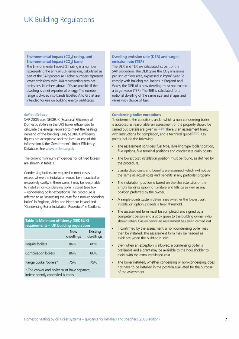
The current minimum efficiencies for oil fired boilers are shown in table 1.
Condensing boilers are required in most cases except where the installation would be impractical or excessively costly. In these cases it may be reasonable to install a non-condensing boiler instead (see box – condensing boiler exceptions). The procedure is referred to as “Assessing the case for a non-condensing boiler” in England, Wales and Northern Ireland and “Condensing Boiler Installation Procedure” in Scotland.
Table 1: Minimum efficiency (SEDBUK) requirements – UK building regulations
New dwellings
Existing dwellings
Regular boilers 86% 86%
Combination boilers 86% 86%
Range cooker/boilers* 75% 75%
* The cooker and boiler must have separate, independently controlled burners
Environmental Impact (CO2) rating, and Environmental Impact (CO2) bandThe Environmental Impact (EI) rating is a number representing the annual CO2 emissions, calculated as part of the SAP procedure. Higher numbers represent lower emissions, with 100 representing zero net emissions. Numbers above 100 are possible if the dwelling is a net exporter of energy. The number range is divided into bands labelled A to G that are intended for use on building energy certificates.
Dwelling emission rate (DER) and target emission rate (TER)The DER and TER are calculated as part of the SAP procedure. The DER gives the CO2 emissions per unit of floor area, expressed in kg/m2/year. To comply with building regulations in England and Wales, the DER of a new dwelling must not exceed a target value (TER). The TER is calculated for a notional dwelling of the same size and shape, and varies with choice of fuel.
Condensing boiler exceptionsTo determine the conditions under which a non-condensing boiler is accepted as reasonable, an assessment of the property should be carried out. Details are given in(19,21). There is an assessment form, with instructions for completion, and a technical guide(23,24). Key points include the following:
The assessment considers fuel type, dwelling type, boiler position, •flue options, flue terminal positions and condensate drain points.
The lowest cost installation position must be found, as defined by •the procedure.
Standardised costs and benefits are assumed, which will not be •the same as actual costs and benefits in any particular property.
The installation position is based on the characteristics of the •empty building, ignoring furniture and fittings as well as any position preferred by the owner.
A simple points system determines whether the lowest cost •installation option exceeds a fixed threshold.
The assessment form must be completed and signed by a •competent person and a copy given to the building owner, who should retain it as evidence an assessment has been carried out.
If confirmed by the assessment, a non-condensing boiler may •then be installed. The assessment form may be needed as evidence when the building is sold.
Even when an exception is allowed, a condensing boiler is •preferable and a grant may be available to the householder to assist with the extra installation cost.
The boiler installed, whether condensing or non-condensing, does •not have to be installed in the position evaluated for the purpose of the assessment.
8 Domestic heating by oil: Boiler systems – guidance for installers and specifiers (2008 edition)
UK Building Regulations
Storage vessels Hot water storage vessels should be insulated in accordance with BS 1566:2002(25), and the internal heat exchanger should be sized accordingly. They must also have a label showing type, capacity, heat loss and performance.
There should be pumped circulation through the primary circuit to the heat exchanger.
System circulationBoth heating and hot water domestic primary circulation systems should have pumped circulation. Existing semi-gravity systems should be converted to fully pumped.
Controls Zone controls should allow different air temperatures to be set for living and sleeping areas (other than in small open-plan flats and other properties where these areas are not separated). In most dwellings, both temperature zones can be controlled by a single time switch or programmer channel. However, in properties with a floor area of more than 150m2, multiple timing zones are required (with no zone larger than 150m2).
Separate timing control should be provided for hot water, unless this is provided by a combi boiler.
Boiler interlock (see Section 5.1) is needed to ensure that the boiler and pump is switched off when neither heat nor hot water is wanted. Thermostatic radiator valves (TRVs) alone do not provide boiler interlock. They must be supplemented by a room thermostat or similar device to turn off the boiler and prevent unnecessary boiler cycling.
A bypass circuit of specified minimum length should be provided if the boiler manufacturer’s instructions require it, in which case it should be fitted with an automatic bypass valve.
Pipework Pipes should be insulated wherever they pass outside the heated living space. In addition, all hot water pipes connected to the hot water cylinder (including the vent pipe and the primary flow and return) should be insulated for at least 1m from the connection. Pipework in unheated areas must be insulated to meet requirements to limit heat loss.
Electrical worksAll electrical works must be carried out to BS 7671(26).
Existing buildings New or replacement hot water storage vessels and controls should meet the same requirements as in new buildings.
Commissioning Upon completion of the installation, the system should be inspected and then brought into service so that it operates efficiently and meets its specified performance levels. Suitable documentary evidence must be provided; examples are OFTEC forms for Installation CD/10(58) and Commissioning CD/11(59)).The owner or occupier should also be given information on the operation and maintenance of the system. Further information on the requirements for commissioning and handover can be found in the Domestic Heating Compliance Guide (England, Wales and Northern Ireland) and in the Technical Standards handbook (Scotland).
England and Wales2.3 GeneralThere are two Approved Documents(18) ADL1 (new dwellings) and ADL2 (existing dwellings) that outline basic requirements, and they are supported by more detail given in the Domestic Heating Compliance Guide(21).
Further information is available from the Communities and Local Government (CLG) planning portal website www.planningportal.gov.uk
Hot waterHot water storage vessels should be insulated in accordance with BS 1566, BS 3198 or BS EN 12897(25,27,28), and the internal heat exchanger should be sized accordingly. There should be pumped circulation through the primary circuit to the heat exchanger. If a thermal store is used, it should meet the requirements of the Waterheater Manufacturers’ Association 1999 performance specification(29).
They must also have a label showing type, capacity, heat loss and performance.
Domestic heating by oil: Boiler systems – guidance for installers and specifiers (2008 edition) 9
UK Building Regulations
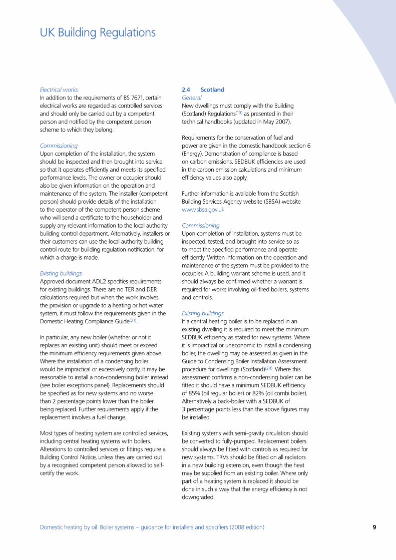
Electrical worksIn addition to the requirements of BS 7671, certain electrical works are regarded as controlled services and should only be carried out by a competent person and notified by the competent person scheme to which they belong.
Commissioning Upon completion of the installation, the system should be inspected and then brought into service so that it operates efficiently and meets its specified performance levels. The owner or occupier should also be given information on the operation and maintenance of the system. The installer (competent person) should provide details of the installation to the operator of the competent person scheme who will send a certificate to the householder and supply any relevant information to the local authority building control department. Alternatively, installers or their customers can use the local authority building control route for building regulation notification, for which a charge is made.
Existing buildings Approved document ADL2 specifies requirements for existing buildings. There are no TER and DER calculations required but when the work involves the provision or upgrade to a heating or hot water system, it must follow the requirements given in the Domestic Heating Compliance Guide(21).
In particular, any new boiler (whether or not it replaces an existing unit) should meet or exceed the minimum efficiency requirements given above. Where the installation of a condensing boiler would be impractical or excessively costly, it may be reasonable to install a non-condensing boiler instead (see boiler exceptions panel). Replacements should be specified as for new systems and no worse than 2 percentage points lower than the boiler being replaced. Further requirements apply if the replacement involves a fuel change.
Most types of heating system are controlled services, including central heating systems with boilers. Alterations to controlled services or fittings require a Building Control Notice, unless they are carried out by a recognised competent person allowed to self-certify the work.
Scotland 2.4 GeneralNew dwellings must comply with the Building (Scotland) Regulations(19) as presented in their technical handbooks (updated in May 2007).
Requirements for the conservation of fuel and power are given in the domestic handbook section 6 (Energy). Demonstration of compliance is based on carbon emissions. SEDBUK efficiencies are used in the carbon emission calculations and minimum efficiency values also apply.
Further information is available from the Scottish Building Services Agency website (SBSA) website www.sbsa.gov.uk
Commissioning Upon completion of installation, systems must be inspected, tested, and brought into service so as to meet the specified performance and operate efficiently. Written information on the operation and maintenance of the system must be provided to the occupier. A building warrant scheme is used, and it should always be confirmed whether a warrant is required for works involving oil-fired boilers, systems and controls.
Existing buildings If a central heating boiler is to be replaced in an existing dwelling it is required to meet the minimum SEDBUK efficiency as stated for new systems. Where it is impractical or uneconomic to install a condensing boiler, the dwelling may be assessed as given in the Guide to Condensing Boiler Installation Assessment procedure for dwellings (Scotland)(24). Where this assessment confirms a non-condensing boiler can be fitted it should have a minimum SEDBUK efficiency of 85% (oil regular boiler) or 82% (oil combi boiler). Alternatively a back-boiler with a SEDBUK of 3 percentage points less than the above figures may be installed.
Existing systems with semi-gravity circulation should be converted to fully-pumped. Replacement boilers should always be fitted with controls as required for new systems. TRVs should be fitted on all radiators in a new building extension, even though the heat may be supplied from an existing boiler. Where only part of a heating system is replaced it should be done in such a way that the energy efficiency is not downgraded.
10 Domestic heating by oil: Boiler systems – guidance for installers and specifiers (2008 edition)
UK Building Regulations
Northern Ireland 2.5 GeneralThe relevant building regulations are the Building Regulations (Northern Ireland) 2000, and specifically Building Regulations F3 and F4(30). These were amended in 2006 and call for ‘reasonable provisions’ to be made for space heating and hot water supply.
The installation, alteration or replacement of any heating system must comply with the relevant regulations. All new heating systems should be notified to building control and any alteration to an existing heating system where a structural alteration is involved. Where an existing heating system is extended, the extension to the system must be insulated to comply with regulation F4.
‘Technical Booklet F1: Conservation of fuel and power’(20) gives provisions that are deemed-to-satisfy the requirements of regulations F3 and F4. Although it is not essential to follow Technical Booklet F1, it is obligatory to comply with building regulations F3 and F4.
Further information is available from the Department of Finance and Personnel, Northern Ireland website www.dfpni.gov.uk
Existing buildings A new boiler (whether or not it replaces an existing unit) should meet or exceed the minimum efficiency requirements given in table 1. Where the installation of a condensing boiler would be impractical or excessively costly, it may be reasonable to install a non-condensing boiler instead (see
panel – condensing boiler exceptions on page 7). Replacements should as specified for new systems and no worse than 2 percentage points lower than the boiler being replaced. Further requirements apply if the replacement involves fuel change.
The technical booklets refer to the Communities and Local Government (CLG) publication: Domestic Heating Compliance Guide(21) for requirements on controlled services, insulation of pipes, ducts and storage vessels.
Hot WaterHot water storage vessels should be insulated in accordance with BS 1566, BS 3198 or BS EN 12897(25,27,28), and the internal heat exchanger should be sized accordingly. There should be pumped circulation through the primary circuit to the heat exchanger. If a thermal store is used, it should meet the requirements of the Waterheater Manufacturers’ Association 1999 performance specification(29).
They must also show a label detailing type, capacity, heat loss and performance.
Commissioning Upon completion of the installation, the system should be inspected and then brought into service so that it operates efficiently and meets its specified performance levels. Local authority building control must be notified of any oil firing, storage, installation and commissioning works. A building notice confirming that all fixed building services have been commissioned by a suitably qualified person is required, and a copy given to the district council and the dwelling owner.
Domestic heating by oil: Boiler systems – guidance for installers and specifiers (2008 edition) 11
Boiler types3.
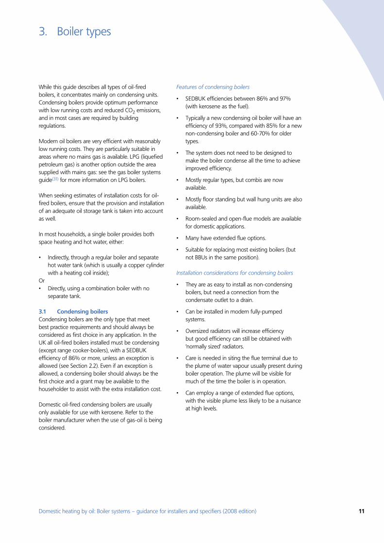
While this guide describes all types of oil-fired boilers, it concentrates mainly on condensing units. Condensing boilers provide optimum performance with low running costs and reduced CO2 emissions, and in most cases are required by building regulations.
Modern oil boilers are very efficient with reasonably low running costs. They are particularly suitable in areas where no mains gas is available. LPG (liquefied petroleum gas) is another option outside the area supplied with mains gas: see the gas boiler systems guide(31) for more information on LPG boilers.
When seeking estimates of installation costs for oil-fired boilers, ensure that the provision and installation of an adequate oil storage tank is taken into account as well.
In most households, a single boiler provides both space heating and hot water, either:
Indirectly, through a regular boiler and separate •hot water tank (which is usually a copper cylinder with a heating coil inside);
Or Directly, using a combination boiler with no •separate tank.
Condensing boilers 3.1 Condensing boilers are the only type that meet best practice requirements and should always be considered as first choice in any application. In the UK all oil-fired boilers installed must be condensing (except range cooker-boilers), with a SEDBUK efficiency of 86% or more, unless an exception is allowed (see Section 2.2). Even if an exception is allowed, a condensing boiler should always be the first choice and a grant may be available to the householder to assist with the extra installation cost.
Domestic oil-fired condensing boilers are usually only available for use with kerosene. Refer to the boiler manufacturer when the use of gas-oil is being considered.
Features of condensing boilers
SEDBUK efficiencies between 86% and 97% •(with kerosene as the fuel).
Typically a new condensing oil boiler will have an •efficiency of 93%, compared with 85% for a new non-condensing boiler and 60-70% for older types.
The system does not need to be designed to •make the boiler condense all the time to achieve improved efficiency.
Mostly regular types, but combis are now •available.
Mostly floor standing but wall hung units are also •available.
Room-sealed and open-flue models are available •for domestic applications.
Many have extended flue options. •
Suitable for replacing most existing boilers (but •not BBUs in the same position).
Installation considerations for condensing boilers
They are as easy to install as non-condensing •boilers, but need a connection from the condensate outlet to a drain.
Can be installed in modern fully-pumped •systems.
Oversized radiators will increase efficiency •but good efficiency can still be obtained with ‘normally sized’ radiators.
Care is needed in siting the flue terminal due to •the plume of water vapour usually present during boiler operation. The plume will be visible for much of the time the boiler is in operation.
Can employ a range of extended flue options, •with the visible plume less likely to be a nuisance at high levels.
12 Domestic heating by oil: Boiler systems – guidance for installers and specifiers (2008 edition)
Boiler types
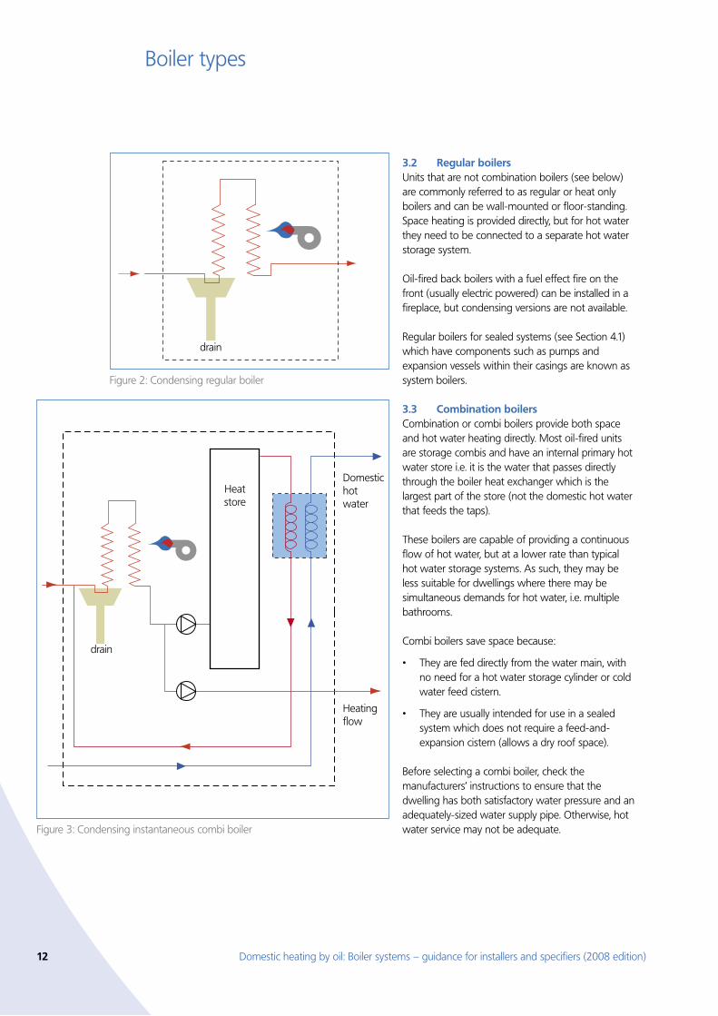
Regular boilers 3.2 Units that are not combination boilers (see below) are commonly referred to as regular or heat only boilers and can be wall-mounted or floor-standing. Space heating is provided directly, but for hot water they need to be connected to a separate hot water storage system.
Oil-fired back boilers with a fuel effect fire on the front (usually electric powered) can be installed in a fireplace, but condensing versions are not available.
Regular boilers for sealed systems (see Section 4.1) which have components such as pumps and expansion vessels within their casings are known as system boilers.
Combination boilers 3.3 Combination or combi boilers provide both space and hot water heating directly. Most oil-fired units are storage combis and have an internal primary hot water store i.e. it is the water that passes directly through the boiler heat exchanger which is the largest part of the store (not the domestic hot water that feeds the taps).
These boilers are capable of providing a continuous flow of hot water, but at a lower rate than typical hot water storage systems. As such, they may be less suitable for dwellings where there may be simultaneous demands for hot water, i.e. multiple bathrooms.
Combi boilers save space because:
They are fed directly from the water main, with •no need for a hot water storage cylinder or cold water feed cistern.
They are usually intended for use in a sealed •system which does not require a feed-and-expansion cistern (allows a dry roof space).
Before selecting a combi boiler, check the manufacturers’ instructions to ensure that the dwelling has both satisfactory water pressure and an adequately-sized water supply pipe. Otherwise, hot water service may not be adequate.
Figure 2: Condensing regular boiler
drain
Domestichotwater
Heatingflow
drain
Heatstore
Figure 3: Condensing instantaneous combi boiler
Domestic heating by oil: Boiler systems – guidance for installers and specifiers (2008 edition) 13
Boiler types
Space heating The power (rate of heat output) of combi boilers is usually governed by hot water service requirements, and often exceeds that needed for space heating. Most oil-fired combis have fixed rate burners and a hot water store.
Hot water Factors to consider are:
The time taken for hot water to reach an •acceptable temperature.
Hot water flow rate at the acceptable •temperature.
How long this rate can be sustained.•
Can hot water be drawn off at more than one •point simultaneously?
These factors will be influenced by the following:
The size of the internal hot water store. A store •can reduce the delay in delivering hot water. Oil-fired combis usually have a primary water store. There are four different types:
Instantaneous: no internal hot water store –(rarely oil-fired).Keep-hot small hot water store: keeps water –within the boiler permanently hot to reduce warm-up time at boiler start-up (sometimes called ‘warm-start’).Medium store: sufficient to meet small hot –water requirements without delay, but insufficient for a bath.Large store: sufficient for a bath or multiple –simultaneous draw-off without delay.
Boiler power affects the rate at which hot water •at the required temperature can be drawn off after any internal store is exhausted.
Boilers generally limit the hot water flow rate to •ensure the declared temperature rise.
Range Cooker boilers 3.4 Some oil-fired cookers have a hot water boiler (either integral or separate).
The latest units have two burners: one is for heating and hot water; the other is for cooking and has independent control. The casings of these cooker boilers have relatively high heat loss, which can be useful in winter but not in summer. Condensing units are being developed but not yet available.
14 Domestic heating by oil: Boiler systems – guidance for installers and specifiers (2008 edition)
Systems and components4.
Systems may either be sealed or open-vented to prevent ingress or escape of air. In the past, most installations were open-vented, but many are now being replaced by sealed systems. Whether a system is sealed or open vented makes no difference to its energy efficiency.
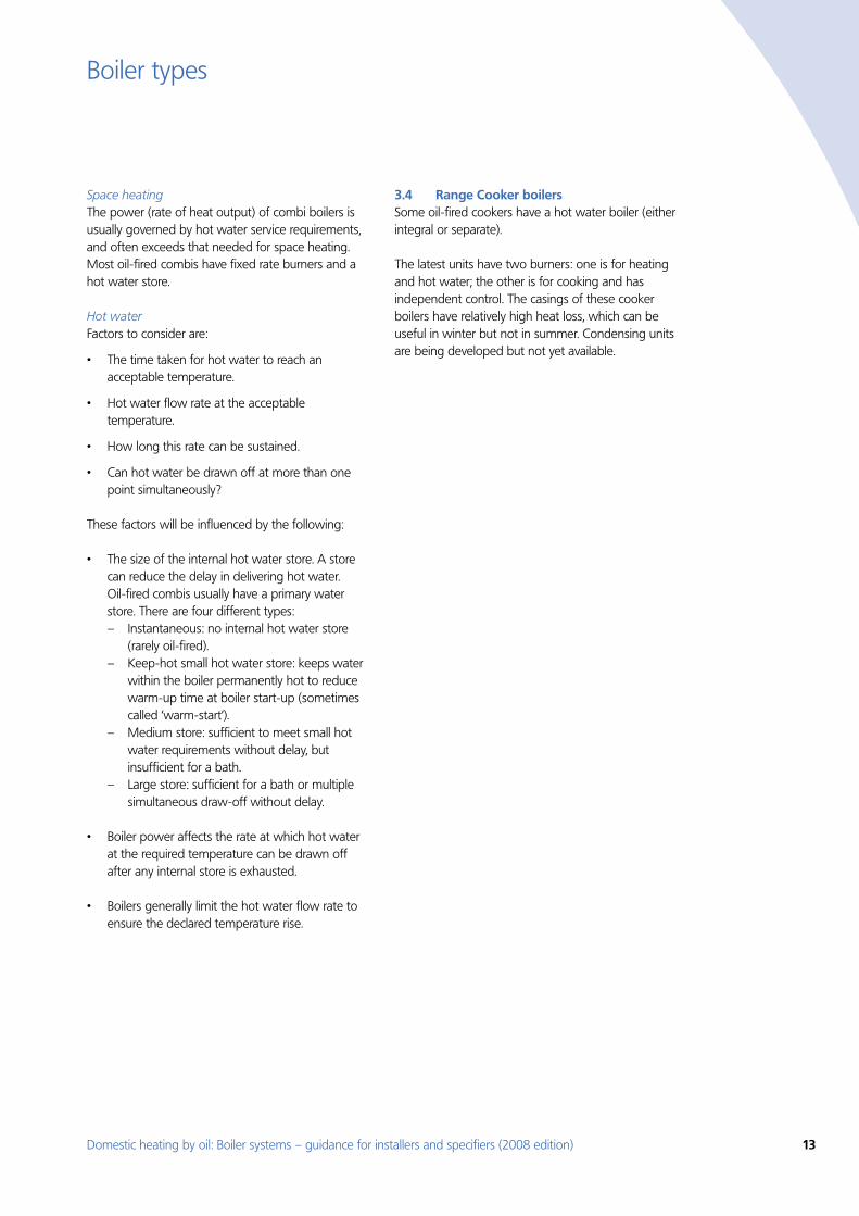
Sealed and open-vented systems 4.1 Sealed This is a popular option for new systems and increasingly used for boiler replacements. The feed-and-expansion cistern is replaced by an expansion vessel incorporating a diaphragm to accommodate variations in water volume. As the system is not open to the atmosphere, the pressure rises with increasing temperature, and additional safety controls must be installed (these are often within the boiler). The system will need a relief valve connected to an external discharge point, which must be placed where any discharge of hot water will be harmless. There is no permanent connection to a water supply, and the system may have to be topped up with water occasionally.
As the system is not open to the atmosphere, there is little possibility of oxygen being absorbed into the water and, consequently, reduced risk of corrosion. Because these systems may remove the need to install pipes and cisterns in the roof space, they reduce the risk of freezing.
Most combi boilers, and all system boilers, are designed for use with sealed systems and will usually incorporate system components, including a pump, expansion vessel and safety controls within the boiler case. In such cases, it must be ensured that this integral expansion vessel has sufficient capacity to allow for the water expansion of the whole system.
Open-vented The majority of existing systems with a regular boiler and an indirect hot water cylinder are open vented. ‘Open vent’ refers to the separate vent pipe which is open to the atmosphere. The system also needs a feed-and-expansion cistern to allow for changes in water volume with temperature. This cistern has to be at the highest point of the system, usually in the loft space where it must be protected against freezing.
Expansion vessel
Figure 4: Sealed system
Feed and expansion cistern
Figure 5: Open system
Domestic heating by oil: Boiler systems – guidance for installers and specifiers (2008 edition) 15
Systems and components
Domestic hot water 4.2 The main issues to be considered regarding domestic hot water are:
The number of people in the dwelling. •
The number of baths/showers/taps.•
The hot water flow rate required. •
Likelihood of simultaneous hot water draw-offs. •
Availability of space for a hot water cylinder, or •storage-combi.
Importance of a dry loft. •
Feasibility of solar water heating. •
Specific issues relating to combis are given in Section 3.3.
Most existing regular boiler systems employ a vented, indirect, hot water storage cylinder. In
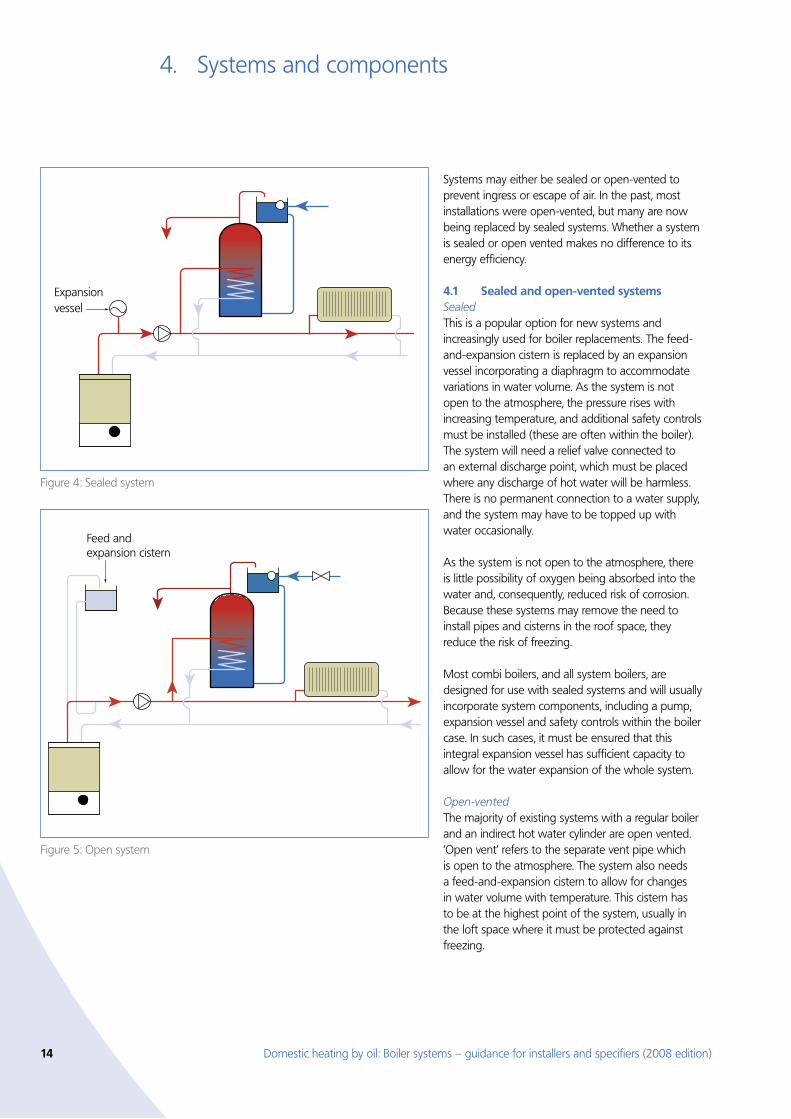
Hot water taps
Cold water taps
Cold water main
Figure 6: Unvented hot water system
households with a single bathroom, these are typically of 117-140 litre capacity, but for larger dwellings with more than one bathroom (and perhaps with separate shower facilities), a larger cylinder capacity will be required(32).
High performance cylinders contain a rapid heating coil. This is a heat exchanger with larger surface than normal, which reduces the time taken to heat the water and may reduce boiler cycling. It gives a valuable reduction in recovery time between large draw-offs (such as baths), and helps to increase system efficiency (especially with older boilers). High performance cylinders often have improved factory-applied insulation as well.
Unvented cylinders are increasingly used in new systems and these operate at mains pressure. They employ an internal expansion facility or a dedicated external expansion vessel, and do not require a feed cistern in the loft.
16 Domestic heating by oil: Boiler systems – guidance for installers and specifiers (2008 edition)
Systems and components
Most hot water cylinders and thermal stores are supplied with factory-applied insulation and these should always be used in preference to cylinders with separate jackets. Cylinders should satisfy British Standards with regard to insulation and heat exchanger performance.
Medium-duty cylinders have inferior performance and do not meet CHeSS basic requirements or those of the building regulations, and so should not be used for either new or replacement installations.
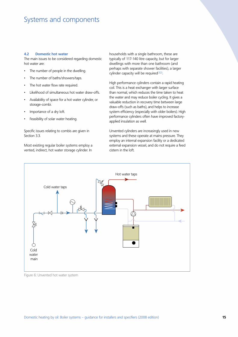
Thermal stores can be obtained that hold water at high temperatures, heated by the boiler directly.
These are available for ‘hot water only’ or ‘hot water and space heating’.
Mains-fed systems such as combi boilers, unvented cylinders and thermal stores can supply hot water at mains pressure. This is extremely beneficial when high pressure is needed at the outlet, e.g. for showers. It is therefore important to ensure that the incoming water supply pressure and flow to the dwelling are adequate and that all showers have the hot and cold water supply at the same nominal pressure. This eliminates the need for a shower pump.
Hot water taps
Feed and expansion cistern
Cold water main
Figure 7: Thermal storage system
Table 2: Domestic hot water flow rates
System type Flow rate
Low Medium High
Instantaneous combi1,3 x x
Storage combi2,3 x x
Thermal store3 x x
Unvented storage2,3 x x
Vented storage4 x x
Notes1. Rarely applied to oil-fired boilers and depends on boiler heat output; less satisfactory for two or more
simultaneous draw-offs2. Depends on boiler heat output and storage capacity3. Depends on adequate mains water supply4. Requires high level feed cistern
Domestic heating by oil: Boiler systems – guidance for installers and specifiers (2008 edition) 17
Systems and components
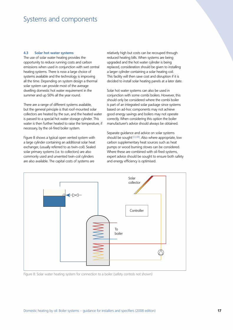
Solar hot water systems4.3 The use of solar water heating provides the opportunity to reduce running costs and carbon emissions when used in conjunction with wet central heating systems. There is now a large choice of systems available and the technology is improving all the time. Depending on system design a thermal solar system can provide most of the average dwelling domestic hot water requirement in the summer and up 50% all the year round.
There are a range of different systems available, but the general principle is that roof-mounted solar collectors are heated by the sun, and the heated water is passed to a special hot water storage cylinder. This water is then further heated to raise the temperature, if necessary, by the oil-fired boiler system.
Figure 8 shows a typical open vented system with a large cylinder containing an additional solar heat exchanger, (usually referred to as twin-coil). Sealed solar primary systems (i.e. to collectors) are also commonly used and unvented twin-coil cylinders are also available. The capital costs of systems are
relatively high but costs can be recouped through reduced heating bills. When systems are being upgraded and the hot water cylinder is being replaced, consideration should be given to installing a larger cylinder containing a solar heating coil. This facility will then save cost and disruption if it is decided to install solar heating panels at a later date.
Solar hot water systems can also be used in conjunction with some combi boilers. However, this should only be considered where the combi boiler is part of an integrated solar package since systems based on ad-hoc components may not achieve good energy savings and boilers may not operate correctly. When considering this option the boiler manufacturer’s advice should always be obtained.
Separate guidance and advice on solar systems should be sought(33,48). Also where appropriate, low carbon supplementary heat sources such as heat pumps or wood burning stoves can be considered. Where these are combined with oil-fired systems, expert advice should be sought to ensure both safety and energy efficiency is optimised.
Controller
Solar collector
To boiler
Figure 8: Solar water heating system for connection to a boiler (safety controls not shown)
18 Domestic heating by oil: Boiler systems – guidance for installers and specifiers (2008 edition)
Systems and components
Upgrading systems 4.4 Many existing wet central heating systems are poorly controlled and of obsolete design. Poor design features which fail to meet current building regulations and best practice requirements include:
Gravity circulation to the hot water cylinder, which •results in stored water being slow to re-heat.
Lack of cylinder thermostat, resulting in excessive •stored water temperature (risk of scalding).
Lack of room thermostat (rooms are too hot). •
Lack of TRVs, causing excessive room •temperatures and poor system balancing.
Absence of boiler interlock, causing the boiler •to stay hot and to cycle unnecessarily during programmed periods.
It is important that an existing system is cleaned, and recommendations regarding the use of corrosion inhibitor are followed when boilers are replaced and/or systems upgraded (57).
When upgrading, use the CHeSS specifications (see Section 6).
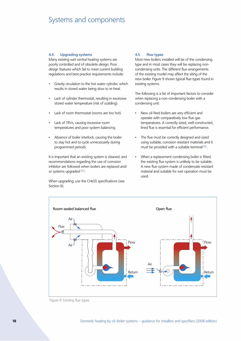
Flue types 4.5 Most new boilers installed will be of the condensing type and in most cases they will be replacing non-condensing units. The different flue arrangements of the existing model may affect the siting of the new boiler. Figure 9 shows typical flue types found in existing systems.
The following is a list of important factors to consider when replacing a non-condensing boiler with a condensing unit:
New oil-fired boilers are very efficient and •operate with comparatively low flue-gas temperatures. A correctly sized, well-constructed, lined flue is essential for efficient performance.
The flue must be correctly designed and sized •using suitable, corrosion resistant materials and it must be provided with a suitable terminal(34).
When a replacement condensing boiler is fitted, •the existing flue system is unlikely to be suitable. A new flue system made of condensate resistant material and suitable for wet operation must be used.
Air
Air
Air
Flow
Return
Flue
Room-sealed balanced flue Open flue
Flow
Return
Figure 9: Existing flue types
Domestic heating by oil: Boiler systems – guidance for installers and specifiers (2008 edition) 19
Systems and components
Many new condensing boilers are room-sealed •with a balanced flue. Room-sealed boilers do not require special provision for combustion air in that room but compartment ventilation may be required for cooling purposes.
Boilers with open flues should, when possible, •be located in a separate boiler room where combustion air is taken directly from the outside. If it is to be installed in a regularly used room such as a kitchen, advice should be sought from the manufacturer.
The plume will be visible for much of the time •the boiler is in use and can sometimes cause a nuisance. For this reason, special consideration should be given to the siting of the new flue terminal (see Section 9.2).
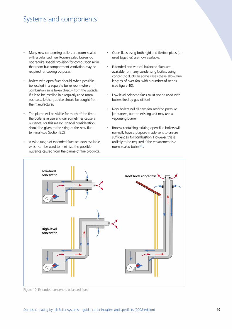
A wide range of extended flues are now available •which can be used to minimize the possible nuisance caused from the plume of flue products.
Open flues using both rigid and flexible pipes (or •used together) are now available.
Extended and vertical balanced flues are •available for many condensing boilers using concentric ducts. In some cases these allow flue lengths of over 6m, with a number of bends. (see figure 10).
Low level balanced flues must not be used with •boilers fired by gas-oil fuel.
New boilers will all have fan-assisted pressure •jet burners, but the existing unit may use a vaporising burner.
Rooms containing existing open-flue boilers will •normally have a purpose-made vent to ensure sufficient air for combustion. However, this is unlikely to be required if the replacement is a room-sealed boiler(34).
Roof level concentric
High-level concentric
Low-level concentric
Figure 10: Extended concentric balanced flues
20 Domestic heating by oil: Boiler systems – guidance for installers and specifiers (2008 edition)
Systems and components
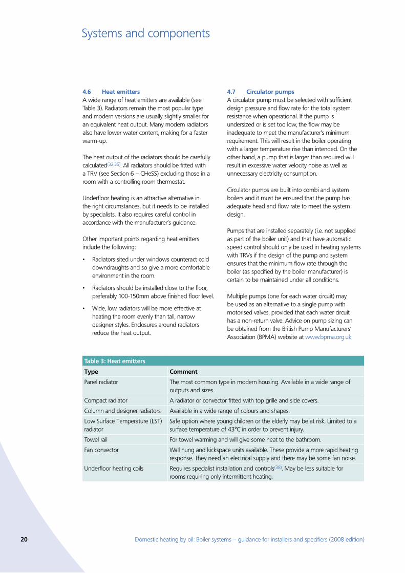
Heat emitters 4.6 A wide range of heat emitters are available (see Table 3). Radiators remain the most popular type and modern versions are usually slightly smaller for an equivalent heat output. Many modern radiators also have lower water content, making for a faster warm-up.
The heat output of the radiators should be carefully calculated(32,35). All radiators should be fitted with a TRV (see Section 6 – CHeSS) excluding those in a room with a controlling room thermostat.
Underfloor heating is an attractive alternative in the right circumstances, but it needs to be installed by specialists. It also requires careful control in accordance with the manufacturer’s guidance.
Other important points regarding heat emitters include the following:
Radiators sited under windows counteract cold •downdraughts and so give a more comfortable environment in the room.
Radiators should be installed close to the floor, •preferably 100-150mm above finished floor level.
Wide, low radiators will be more effective at •heating the room evenly than tall, narrow designer styles. Enclosures around radiators reduce the heat output.
Circulator pumps 4.7 A circulator pump must be selected with sufficient design pressure and flow rate for the total system resistance when operational. If the pump is undersized or is set too low, the flow may be inadequate to meet the manufacturer’s minimum requirement. This will result in the boiler operating with a larger temperature rise than intended. On the other hand, a pump that is larger than required will result in excessive water velocity noise as well as unnecessary electricity consumption.
Circulator pumps are built into combi and system boilers and it must be ensured that the pump has adequate head and flow rate to meet the system design.
Pumps that are installed separately (i.e. not supplied as part of the boiler unit) and that have automatic speed control should only be used in heating systems with TRVs if the design of the pump and system ensures that the minimum flow rate through the boiler (as specified by the boiler manufacturer) is certain to be maintained under all conditions.
Multiple pumps (one for each water circuit) may be used as an alternative to a single pump with motorised valves, provided that each water circuit has a non-return valve. Advice on pump sizing can be obtained from the British Pump Manufacturers’ Association (BPMA) website at www.bpma.org.uk
Table 3: Heat emitters
Type Comment
Panel radiator The most common type in modern housing. Available in a wide range of outputs and sizes.
Compact radiator A radiator or convector fitted with top grille and side covers.
Column and designer radiators Available in a wide range of colours and shapes.
Low Surface Temperature (LST) radiator
Safe option where young children or the elderly may be at risk. Limited to a surface temperature of 43°C in order to prevent injury.
Towel rail For towel warming and will give some heat to the bathroom.
Fan convector Wall hung and kickspace units available. These provide a more rapid heating response. They need an electrical supply and there may be some fan noise.
Underfloor heating coils Requires specialist installation and controls(38). May be less suitable for rooms requiring only intermittent heating.
Domestic heating by oil: Boiler systems – guidance for installers and specifiers (2008 edition) 21
Controls5.
Installing effective controls can have a major impact on the energy consumption of heating and hot water systems. This section describes the types of controls now available and outlines which are most suitable for different heating systems.
Effective controls will increase operating efficiencies, especially when older systems are being updated. They also provide the householder with the opportunity to minimise energy consumption by ensuring the right comfort temperatures are maintained and so reducing overheating. Reducing room temperatures will also save energy (see panel opposite). Timed space and water heating periods will also help to avoid excessive use of energy. Heating fuel is expensive (oil-fired boilers typically consume 40-80 pence of fuel an hour when operating) and reducing the firing time will make a proportionate difference to running costs.
A good control system is one which ensures the boiler does not operate unless there is a demand and that only provides heat where and when it is needed in order to achieve the required temperatures. The selection of suitable controls plays a key part in minimising the overall running costs of a heating or hot water system.
Control standards must meet best practice in order to maximise the efficiency of a heating system. However, in order just to achieve the SEDBUK efficiency claimed for a boiler, at least the basic set of controls given in CHeSS must be installed (see Section 6).
The cost benefit of controls should not be underestimated. Upgrading the controls on older heating systems can save up to 18% on energy bills, for example when a full set of controls is fitted to a system which previously had none. This is important, as over 80% of the energy a householder uses in the home is for space and hot water heating.
Individual controls5.1 This section describes the range of controls commonly used in oil-fired systems, what they do and why they are important.
The controls listed here are normally installed separately from the boiler although some may be incorporated within it. For clarity of specification, Appendix C contains a full list of controls including those often fitted within appliances and gives industry-agreed definitions. Appendix E provides simple explanations that can be given to householders on what controls do and how they should be used.
Further advice on controls most suitable for the disabled, particularly with visual and dexterity impairment, can be found in the Ricability report(37).
In the following listing, best practice controls are noted.
Time switchA simple time control that will only switch one circuit. It should be chosen so that it is easy to understand and reset, especially when there is a change to the householder’s domestic routine.
ProgrammerThis can switch two circuits separately (usually heating and hot water). There are two basic types:
A standard programmer uses the same time •settings for space heating and hot water.
A full programmer allows fully independent time •setting for space and hot water heating.
Energy savings from good controls
Installing a minimum standard of controls on a system •which previously had none can reduce fuel consumption and CO2 emissions by 18%.
Reducing higher than necessary room temperatures will •cut energy use. Turning down the room thermostat by 1°C will reduce space heating consumption by 6-10%.
An easy to use programmer that is adjusted to match the •householder’s occupancy pattern helps reduce wasteful heating when no one is at home.
VAT on heating controlsHeating controls for domestic wet central heating systems are recognized by the Government as an energy efficiency measure. VAT is therefore charged at a lower rate – currently 5% instead of the full rate of 17.5%. This lower rate applies to both equipment and installation costs, but only when the work is carried out by an installer registered for VAT.
22 Domestic heating by oil: Boiler systems – guidance for installers and specifiers (2008 edition)
Controls
Room thermostatA simple room temperature control. Traditional types use expansion/contraction (e.g. bimetallic strip) to operate a switch or relay. They usually include an accelerator or anticipator, which is a small resistance heater having the effect of smoothing out the temperature cycle by preventing overshoot.
Electronic room thermostats are also available which can react more rapidly to temperature change. Some of the latest units include a function to control the boiler firing frequency. These units are designed to minimise the variations in both the boiler and room temperature.
Wireless units that provide increased flexibility in positioning and eliminate visible wiring are now commonly used.
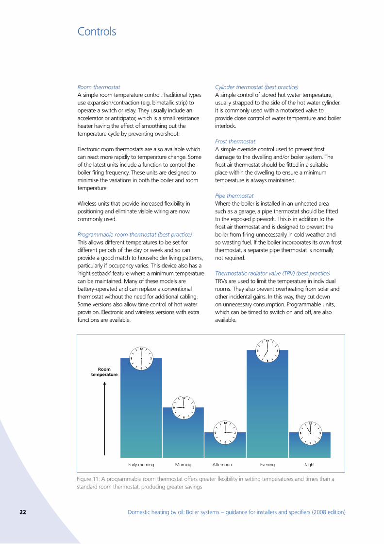
Programmable room thermostat (best practice) This allows different temperatures to be set for different periods of the day or week and so can provide a good match to householder living patterns, particularly if occupancy varies. This device also has a ‘night setback’ feature where a minimum temperature can be maintained. Many of these models are battery-operated and can replace a conventional thermostat without the need for additional cabling. Some versions also allow time control of hot water provision. Electronic and wireless versions with extra functions are available.
Cylinder thermostat (best practice) A simple control of stored hot water temperature, usually strapped to the side of the hot water cylinder. It is commonly used with a motorised valve to provide close control of water temperature and boiler interlock.
Frost thermostat A simple override control used to prevent frost damage to the dwelling and/or boiler system. The frost air thermostat should be fitted in a suitable place within the dwelling to ensure a minimum temperature is always maintained.
Pipe thermostatWhere the boiler is installed in an unheated area such as a garage, a pipe thermostat should be fitted to the exposed pipework. This is in addition to the frost air thermostat and is designed to prevent the boiler from firing unnecessarily in cold weather and so wasting fuel. If the boiler incorporates its own frost thermostat, a separate pipe thermostat is normally not required.
Thermostatic radiator valve (TRV) (best practice) TRVs are used to limit the temperature in individual rooms. They also prevent overheating from solar and other incidental gains. In this way, they cut down on unnecessary consumption. Programmable units, which can be timed to switch on and off, are also available.
Figure 11: A programmable room thermostat offers greater flexibility in setting temperatures and times than a standard room thermostat, producing greater savings
MorningEarly morning Afternoon
Roomtemperature
Evening Night
Domestic heating by oil: Boiler systems – guidance for installers and specifiers (2008 edition) 23
Controls
Thermostatic hot water temperature limit valveThese self-acting valves without motors are used to limit hot water temperature in domestic hot water cylinders. Some units sense primary water (boiler) temperature, others have a separate remote sensor for stored water temperature. Cylinder controls should not be used with these unless they also operate an electrical switch to provide boiler interlock, otherwise the boiler will cycle unnecessarily.
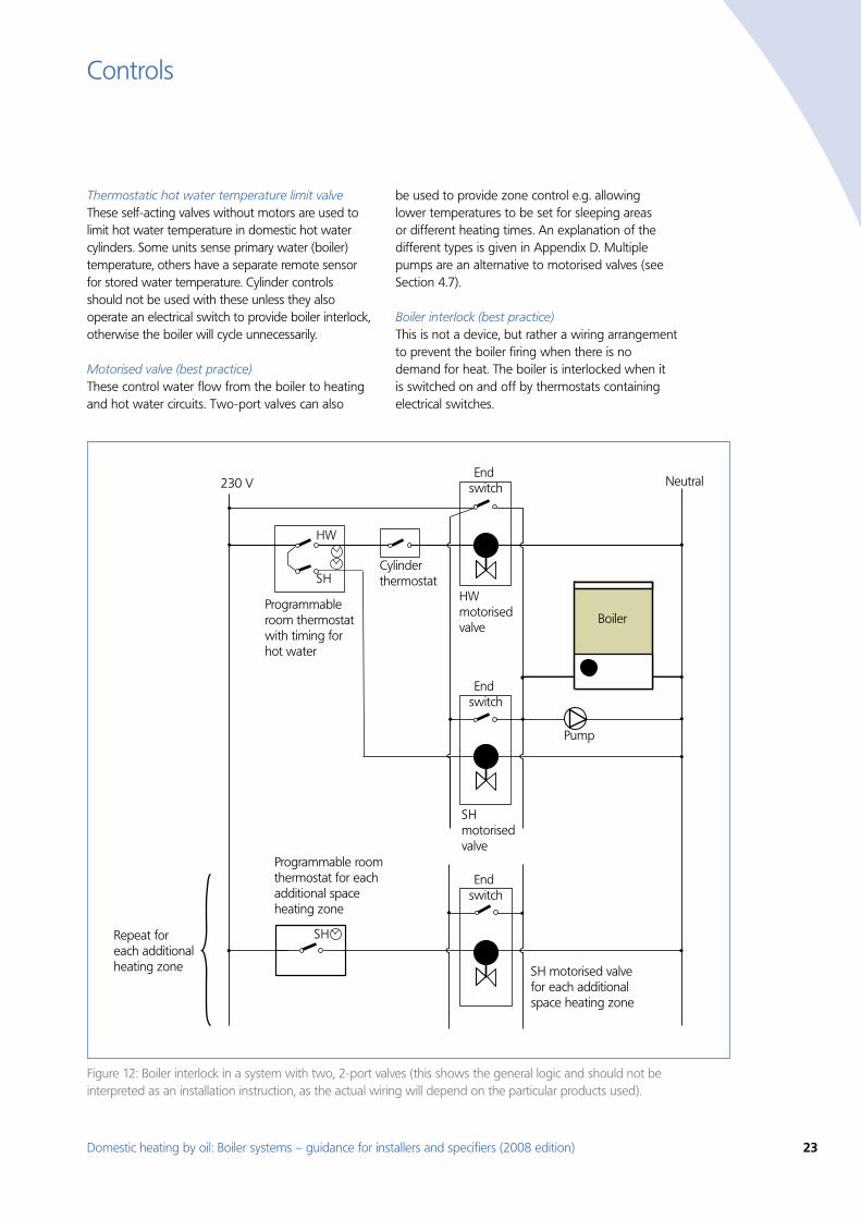
Motorised valve (best practice)These control water flow from the boiler to heating and hot water circuits. Two-port valves can also
be used to provide zone control e.g. allowing lower temperatures to be set for sleeping areas or different heating times. An explanation of the different types is given in Appendix D. Multiple pumps are an alternative to motorised valves (see Section 4.7).
Boiler interlock (best practice)This is not a device, but rather a wiring arrangement to prevent the boiler firing when there is no demand for heat. The boiler is interlocked when it is switched on and off by thermostats containing electrical switches.
Figure 12: Boiler interlock in a system with two, 2-port valves (this shows the general logic and should not be interpreted as an installation instruction, as the actual wiring will depend on the particular products used).
SH
Programmable roomthermostat for each additional spaceheating zone
SH motorised valvefor each additional space heating zone
End switch
End switch
End switch
Pump
Cylinderthermostat
Programmableroom thermostat with timing for hot water
HW
SH
Boiler
HW motorisedvalve
230 V Neutral
SH motorisedvalve
Repeat for each additional heating zone
24 Domestic heating by oil: Boiler systems – guidance for installers and specifiers (2008 edition)
Controls
All thermostats in the heating system fitted with electrical switches should be wired in this way. This includes room thermostats, programmable room thermostats, cylinder thermostats and some types of boiler energy managers. In many cases, the interlock is also applied to the operation of the pump, although any requirements for pump overrun stipulated by the boiler manufacturer must be observed. Without interlock, a boiler is likely to cycle on an off regularly, wasting energy by keeping hot unnecessarily.
Achieving interlock depends upon the boiler type and the controls fitted. Typical examples of boiler interlock are as follows:
Regular boiler with one 3-port or at least two •2-port motorised valves. The interlock is usually arranged so that the room or cylinder thermostat switches the power supply to the boiler (and sometimes the pump) through the motorised valve ‘end’ switches. In other words, electrical power from the programmable room thermostat (or separate programmer and room thermostat) and the cylinder thermostat will drive the valve motor to the open position. Once the motor is fully open, the end-switch will close and electrical power is then passed to the boiler (and pump). Once the power to the valve is removed (programmer off-period, or thermostat is satisfied) the motorised valve will close, the end-switch will open, and the boiler and pump will stop.
Regular boiler with two separate pumps for •heating and hot water. Where separate pumps are used, advice from the manufacturer is needed in regard to the correct use of relays, check valves, etc.
Combi boiler only requires a time switch and •room thermostat (or programmable room thermostat) connection to provide interlock as hot water delivery is controlled directly by the boiler.
A boiler energy manager may need a different wiring arrangement, achieving interlock by an alternative method.
Automatic bypass valve (best practice)This controls water flow according to the differential pressure of the water across it. It is used to maintain a minimum flow rate through the boiler and to limit the circulation pressure when alternative water paths are closed. A bypass circuit must be installed if the boiler manufacturer requires one, or specifies that a minimum flow rate has to be maintained while the boiler is firing. The installed bypass circuit must then include an automatic bypass valve, not a manual (fixed) position valve.
The use of an automatic bypass is important where the system includes a large number of TRVs. When most of these are open, the automatic bypass remains closed, allowing the full water flow to circulate around the heating system. As the TRVs start to close, the automatic bypass starts to open, maintaining the appropriate water flow through the boiler. It is also helps to reduce noise in the system caused by excess water velocity.
An automatic bypass is always preferable to a fixed bypass. With a fixed bypass, there is a constant flow of hot water coming out of the boiler, which is fed directly into the return at all times. This means that the boiler operates at a higher temperature, reducing efficiency and restricting the amount of heat transferred to the system.
It is very important that both automatic and fixed bypasses are correctly adjusted. Poor adjustment will give rise to increased boiler return temperatures and reduced boiler efficiency.
Particular care is required when selecting a pump with automatic speed control for a system with an automatic bypass. It is important to ensure that the boiler manufacturer’s minimum recommended water flow rate is maintained under all operating conditions.
Boiler energy managerThese are self-contained devices which have a number of the functions found in other individual controls described in this section. They usually have a number of control functions including weather or load compensation, and sometimes optimum start, frost protection, night setback, anti-cycling control and hot water override. Table 4 lists a range of control functions which may be included.
Domestic heating by oil: Boiler systems – guidance for installers and specifiers (2008 edition) 25
Controls
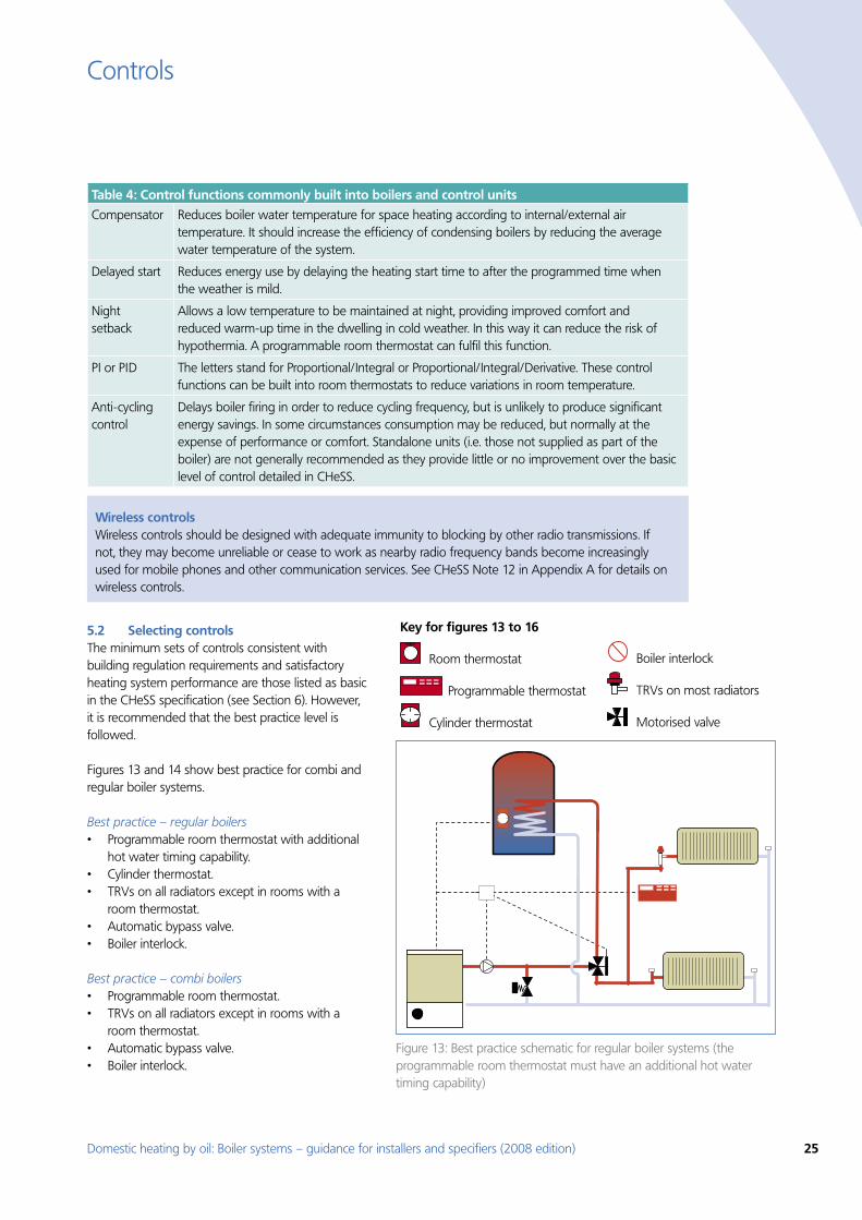
Selecting controls 5.2 The minimum sets of controls consistent with building regulation requirements and satisfactory heating system performance are those listed as basic in the CHeSS specification (see Section 6). However, it is recommended that the best practice level is followed.
Figures 13 and 14 show best practice for combi and regular boiler systems.
Best practice – regular boilersProgrammable room thermostat with additional •hot water timing capability.Cylinder thermostat.•TRVs on all radiators except in rooms with a •room thermostat.Automatic bypass valve.•Boiler interlock.•
Best practice – combi boilersProgrammable room thermostat. •TRVs on all radiators except in rooms with a •room thermostat.Automatic bypass valve.•Boiler interlock.•
Wireless controlsWireless controls should be designed with adequate immunity to blocking by other radio transmissions. If not, they may become unreliable or cease to work as nearby radio frequency bands become increasingly used for mobile phones and other communication services. See CHeSS Note 12 in Appendix A for details on wireless controls.
Figure 13: Best practice schematic for regular boiler systems (the programmable room thermostat must have an additional hot water timing capability)
Table 4: Control functions commonly built into boilers and control units
Compensator Reduces boiler water temperature for space heating according to internal/external air temperature. It should increase the efficiency of condensing boilers by reducing the average water temperature of the system.
Delayed start Reduces energy use by delaying the heating start time to after the programmed time when the weather is mild.
Night setback
Allows a low temperature to be maintained at night, providing improved comfort and reduced warm-up time in the dwelling in cold weather. In this way it can reduce the risk of hypothermia. A programmable room thermostat can fulfil this function.
PI or PID The letters stand for Proportional/Integral or Proportional/Integral/Derivative. These control functions can be built into room thermostats to reduce variations in room temperature.
Anti-cycling control
Delays boiler firing in order to reduce cycling frequency, but is unlikely to produce significant energy savings. In some circumstances consumption may be reduced, but normally at the expense of performance or comfort. Standalone units (i.e. those not supplied as part of the boiler) are not generally recommended as they provide little or no improvement over the basic level of control detailed in CHeSS.
Key for figures 13 to 16
Room thermostat
Programmable thermostat
Cylinder thermostat
Boiler interlock
TRVs on most radiators
Motorised valve
26 Domestic heating by oil: Boiler systems – guidance for installers and specifiers (2008 edition)
Controls
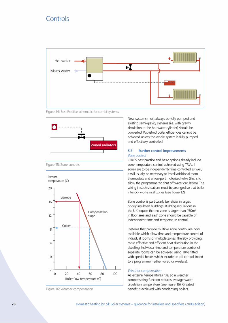
New systems must always be fully pumped and existing semi-gravity systems (i.e. with gravity circulation to the hot water cylinder) should be converted. Published boiler efficiencies cannot be achieved unless the whole system is fully pumped and effectively controlled.
Further control improvements 5.3 Zone controlCHeSS best practice and basic options already include zone temperature control, achieved using TRVs. If zones are to be independently time controlled as well, it will usually be necessary to install additional room thermostats and a two-port motorised valve (this is to allow the programmer to shut off water circulation). The wiring in such situations must be arranged so that boiler interlock works in all zones (see figure 12).
Zone control is particularly beneficial in larger, poorly insulated buildings. Building regulations in the UK require that no zone is larger than 150m2 in floor area and each zone should be capable of independent time and temperature control.
Systems that provide multiple zone control are now available which allow time and temperature control of individual rooms or multiple zones, thereby providing more effective and efficient heat distribution in the dwelling. Individual time and temperature control of separate rooms can be achieved using TRVs fitted with special heads which include on-off control linked to a programmer (either wired or wireless).
Weather compensationAs external temperatures rise, so a weather compensating function reduces average water circulation temperature (see figure 16). Greatest benefit is achieved with condensing boilers.
Figure 15: Zone controls
Zoned radiators
Figure 16: Weather compensation
20
16
12
8
4
0
-4
Externaltemperature (C)
Warmer
Cooler
Compensationslope
Boiler flow temperature (C)
0 20 40 60 80 100
Figure 14: Best Practice schematic for combi systems
Mains water
Hot water
Domestic heating by oil: Boiler systems – guidance for installers and specifiers (2008 edition) 27
Controls
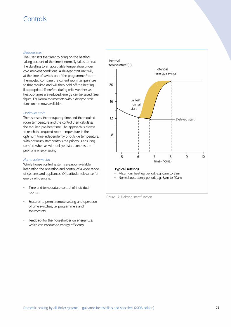
Delayed start The user sets the timer to bring on the heating taking account of the time it normally takes to heat the dwelling to an acceptable temperature under cold ambient conditions. A delayed start unit will, at the time of switch-on of the programmer/room thermostat, compare the current room temperature to that required and will then hold off the heating if appropriate. Therefore during mild weather, as heat-up times are reduced, energy can be saved (see figure 17). Room thermostats with a delayed start function are now available.
Optimum start The user sets the occupancy time and the required room temperature and the control then calculates the required pre-heat time. The approach is always to reach the required room temperature in the optimum time independently of outside temperature. With optimum start controls the priority is ensuring comfort whereas with delayed start controls the priority is energy saving.
Home automationWhole house control systems are now available, integrating the operation and control of a wide range of systems and appliances. Of particular relevance for energy efficiency is:
Time and temperature control of individual •rooms.
Features to permit remote setting and operation •of time switches, i.e. programmers and thermostats.
Feedback for the householder on energy use, •which can encourage energy efficiency.
Potentialenergy savings
Earliest normalstart
Internaltemperature (C)
Time (hours)5 6 7 8 9 10
20
16
12
8
Delayed start
Typical settings• Maximum heat up period, e.g. 6am to 8am• Normal occupancy period, e.g. 8am to 10am
Figure 17: Delayed start function
28 Domestic heating by oil: Boiler systems – guidance for installers and specifiers (2008 edition)
Central Heating System Specifications (CHeSS)6.
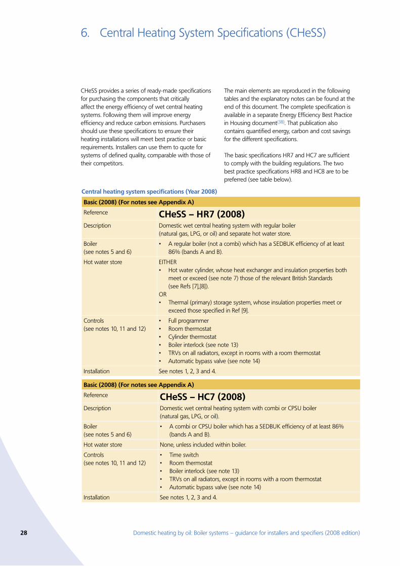
CHeSS provides a series of ready-made specifications for purchasing the components that critically affect the energy efficiency of wet central heating systems. Following them will improve energy efficiency and reduce carbon emissions. Purchasers should use these specifications to ensure their heating installations will meet best practice or basic requirements. Installers can use them to quote for systems of defined quality, comparable with those of their competitors.
The main elements are reproduced in the following tables and the explanatory notes can be found at the end of this document. The complete specification is available in a separate Energy Efficiency Best Practice in Housing document(38). That publication also contains quantified energy, carbon and cost savings for the different specifications.
The basic specifications HR7 and HC7 are sufficient to comply with the building regulations. The two best practice specifications HR8 and HC8 are to be preferred (see table below).
Central heating system specifications (Year 2008)
Basic (2008) (For notes see Appendix A)
Reference CHeSS – HR7 (2008)Description Domestic wet central heating system with regular boiler
(natural gas, LPG, or oil) and separate hot water store.
Boiler (see notes 5 and 6)
A regular boiler (not a combi) which has a SEDBUK efficiency of at least •86% (bands A and B).
Hot water store EITHER Hot water cylinder, whose heat exchanger and insulation properties both •meet or exceed (see note 7) those of the relevant British Standards (see Refs [7],[8]).
ORThermal (primary) storage system, whose insulation properties meet or •exceed those specified in Ref [9].
Controls (see notes 10, 11 and 12)
Full programmer•Room thermostat•Cylinder thermostat•Boiler interlock (see note 13)•TRVs on all radiators, except in rooms with a room thermostat•Automatic bypass valve (see note 14)•
Installation See notes 1, 2, 3 and 4.
Basic (2008) (For notes see Appendix A)
Reference CHeSS – HC7 (2008)Description Domestic wet central heating system with combi or CPSU boiler
(natural gas, LPG, or oil).
Boiler (see notes 5 and 6)
A combi or CPSU boiler which has a SEDBUK efficiency of at least 86% •(bands A and B).
Hot water store None, unless included within boiler.
Controls (see notes 10, 11 and 12)
Time switch•Room thermostat•Boiler interlock (see note 13)•TRVs on all radiators, except in rooms with a room thermostat•Automatic bypass valve (see note 14)•
Installation See notes 1, 2, 3 and 4.
Domestic heating by oil: Boiler systems – guidance for installers and specifiers (2008 edition) 29
Central Heating System Specifications (CHeSS)
Central Heating System Specifications (Year 2008)
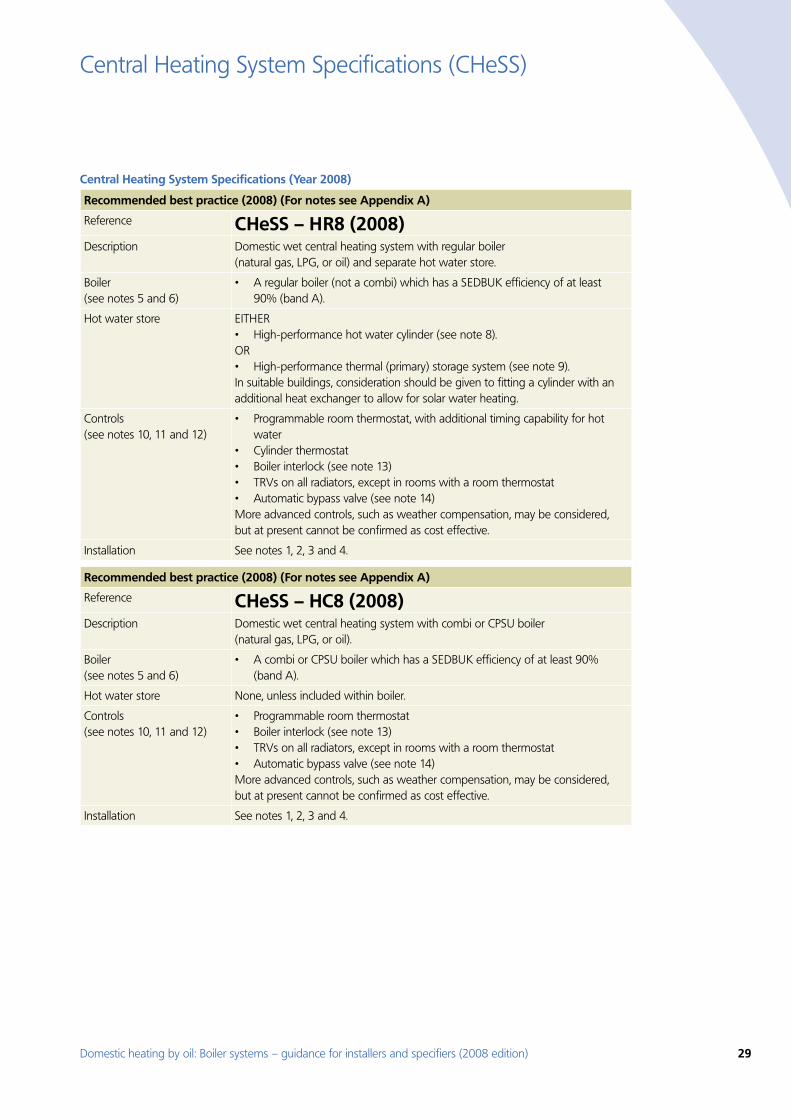
Recommended best practice (2008) (For notes see Appendix A)
Reference CHeSS – HR8 (2008)Description Domestic wet central heating system with regular boiler
(natural gas, LPG, or oil) and separate hot water store.
Boiler (see notes 5 and 6)
A regular boiler (not a combi) which has a SEDBUK efficiency of at least •90% (band A).
Hot water store EITHER High-performance hot water cylinder (see note 8).•
OR High-performance thermal (primary) storage system (see note 9).•
In suitable buildings, consideration should be given to fitting a cylinder with an additional heat exchanger to allow for solar water heating.
Controls (see notes 10, 11 and 12)
Programmable room thermostat, with additional timing capability for hot •waterCylinder thermostat•Boiler interlock (see note 13)•TRVs on all radiators, except in rooms with a room thermostat•Automatic bypass valve (see note 14)•
More advanced controls, such as weather compensation, may be considered, but at present cannot be confirmed as cost effective.
Installation See notes 1, 2, 3 and 4.
Recommended best practice (2008) (For notes see Appendix A)
Reference CHeSS – HC8 (2008)Description Domestic wet central heating system with combi or CPSU boiler
(natural gas, LPG, or oil).
Boiler (see notes 5 and 6)
A combi or CPSU boiler which has a SEDBUK efficiency of at least 90% •(band A).
Hot water store None, unless included within boiler.
Controls (see notes 10, 11 and 12)
Programmable room thermostat•Boiler interlock (see note 13)•TRVs on all radiators, except in rooms with a room thermostat•Automatic bypass valve (see note 14)•
More advanced controls, such as weather compensation, may be considered, but at present cannot be confirmed as cost effective.
Installation See notes 1, 2, 3 and 4.
30 Domestic heating by oil: Boiler systems – guidance for installers and specifiers (2008 edition)
Energy Efficiency7.
The information in this guide is designed to improve the energy efficiency of dwellings. Selecting the most energy efficient boilers suitable for the particular application is vital. Several factors need to be considered when choosing a boiler:
Seasonal (i.e. annual in-use) efficiency. •
Typical heating and hot water running costs for •the dwelling(s).
Typical CO• 2 emissions for space and water heating.
Comparing boiler efficiencies 7.1 The term ‘boiler efficiency’ needs some explanation since there are many values that may be quoted, and these are calculated in different ways. In any comparison of the efficiency of alternative products, it is essential to ensure that the same method is being used.
The efficiency value now used in the Government’s Standard Assessment Procedure and in the building regulations is known by the acronym SEDBUK, (Seasonal Efficiency of a Domestic Boiler in the UK). SEDBUK represents the best estimate presently available of overall seasonal in-use boiler efficiency for space heating and hot water in UK dwellings. It is used throughout this guide as well as in CHeSS, the Energy Saving Trust’s Energy Efficiency Recommended scheme, and other programmes designed to promote efficient boilers.
A boiler’s SEDBUK efficiency is an indicator of the average annual boiler efficiency determined by the amount of heat delivered to the primary (boiler water) heating circuit. It is assumed that the boiler is installed in a fully-pumped system which has been correctly designed and which has adequate controls. The claimed SEDBUK efficiency level will not be achieved otherwise.
The SEDBUK calculation process (which can be found in Appendix D of the SAP[22]) uses actual boiler test data, the measurements being taken by methods defined in European standards to meet the requirements of the European Boiler Efficiency Directive(39). This provides manufacturers with an incentive to make their products as efficient as possible.
As SEDBUK has been designed specifically for SAP energy rating purposes, it takes account of heat losses associated with space and water heating, however it does not include surface heat losses from any hot water store within or external to the boiler. These are treated separately as they may provide a small amount of useful heat to the dwelling during the heating season. This is important when comparing products, as stores with high heat losses will increase annual energy consumption but do not affect SEDBUK values.
The best source of SEDBUK figures is the Boiler Efficiency Database (see Section 7.5). Where this is not available, purchasers should look for this standard form of words in manufacturers’ literature:
“Seasonal efficiency (SEDBUK) = [x]% The value is used in the UK Government’s Standard Assessment Procedure (SAP) for energy rating of dwellings. The test data from which it has been calculated have been certified by [name and/or certification of Notified Body]. ”
Energy efficiency figures calculated by other methods may not be consistent with SEDBUK, and should be disregarded.
Figure 18 shows typical SEDBUK efficiencies for both new and older boilers. In practice there are limits both to the minimum efficiency due to the requirements of the Boiler Efficiency Directive, and to the maximum permitted value based on theoretical considerations.
Minimising demandWhilst this guide aims to improve heating and hot water systems through careful selection of boilers and controls, it is important to remember that other factors affect the overall energy efficiency of the dwelling. In particular, it is essential to minimise:
Fabric heat loss through walls, floors, roofs and •windows.
Ventilation heat loss from windows, unused •chimneys and cracks or gaps in the structure of the dwelling.
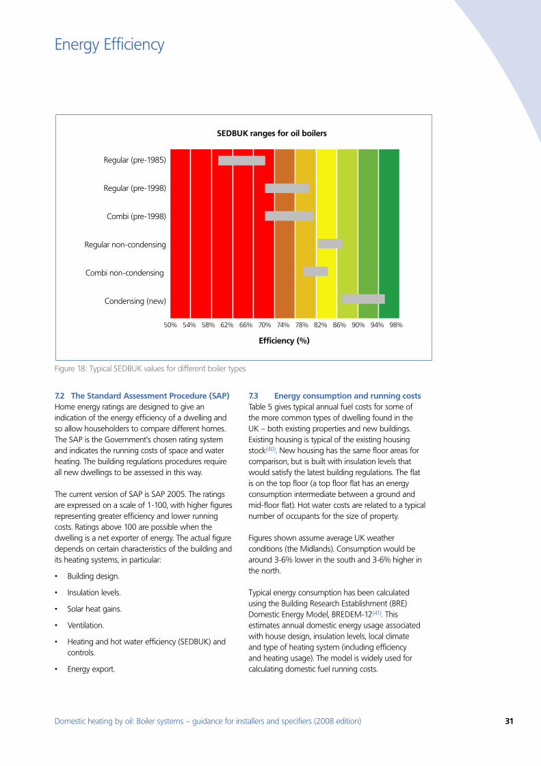
Domestic heating by oil: Boiler systems – guidance for installers and specifiers (2008 edition) 31
Energy Efficiency
The Standard Assessment Procedure (SAP) 7.2 Home energy ratings are designed to give an indication of the energy efficiency of a dwelling and so allow householders to compare different homes. The SAP is the Government’s chosen rating system and indicates the running costs of space and water heating. The building regulations procedures require all new dwellings to be assessed in this way.
The current version of SAP is SAP 2005. The ratings are expressed on a scale of 1-100, with higher figures representing greater efficiency and lower running costs. Ratings above 100 are possible when the dwelling is a net exporter of energy. The actual figure depends on certain characteristics of the building and its heating systems, in particular:
Building design. •
Insulation levels. •
Solar heat gains. •
Ventilation. •
Heating and hot water efficiency (SEDBUK) and •controls.
Energy export.•
Energy consumption and running costs 7.3 Table 5 gives typical annual fuel costs for some of the more common types of dwelling found in the UK – both existing properties and new buildings. Existing housing is typical of the existing housing stock(40). New housing has the same floor areas for comparison, but is built with insulation levels that would satisfy the latest building regulations. The flat is on the top floor (a top floor flat has an energy consumption intermediate between a ground and mid-floor flat). Hot water costs are related to a typical number of occupants for the size of property.
Figures shown assume average UK weather conditions (the Midlands). Consumption would be around 3-6% lower in the south and 3-6% higher in the north.
Typical energy consumption has been calculated using the Building Research Establishment (BRE) Domestic Energy Model, BREDEM-12(41). This estimates annual domestic energy usage associated with house design, insulation levels, local climate and type of heating system (including efficiency and heating usage). The model is widely used for calculating domestic fuel running costs.
Regular (pre-1985)
Regular (pre-1998)
Combi (pre-1998)
Regular non-condensing
Combi non-condensing
Condensing (new)
SEDBUK ranges for oil boilers
Efficiency (%)
50% 54% 58% 62% 66% 70% 74% 78% 82% 86% 90% 94% 98%
Figure 18: Typical SEDBUK values for different boiler types
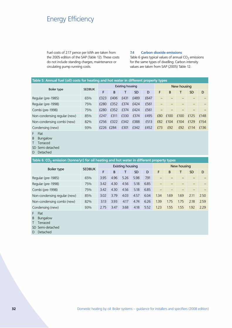
32 Domestic heating by oil: Boiler systems – guidance for installers and specifiers (2008 edition)
Energy Efficiency
Fuel costs of 2.17 pence per kWh are taken from the 2005 edition of the SAP (Table 12). These costs do not include standing charges, maintenance or circulating pump running costs.
Carbon dioxide emissions 7.4 Table 6 gives typical values of annual CO2 emissions for the same types of dwelling. Carbon intensity values are taken from SAP (2005) Table 12.
Table 5: Annual fuel (oil) costs for heating and hot water in different property types
Boiler type SEDBUKExisting housing New housing
F B T SD D F B T SD D
Regular (pre-1985) 65% £323 £406 £431 £489 £647 – – – – –
Regular (pre-1998) 75% £280 £352 £374 £424 £561 – – – – –
Combi (pre-1998) 75% £280 £352 £374 £424 £561 – – – – –
Non-condensing regular (new) 85% £247 £311 £330 £374 £495 £80 £100 £100 £125 £148
Non-condensing combi (new) 82% £256 £322 £342 £388 £513 £82 £104 £104 £129 £154
Condensing (new) 93% £226 £284 £301 £342 £452 £73 £92 £92 £114 £136
F FlatB Bungalow T Terraced SD Semi-detached D Detached
Table 6: CO2 emission (tonne/yr) for oil heating and hot water in different property types
Boiler type SEDBUKExisting housing New housing
F B T SD D F B T SD D
Regular (pre-1985) 65% 3.95 4.96 5.26 5.98 7.91 – – – – –
Regular (pre-1998) 75% 3.42 4.30 4.56 5.18 6.85 – – – – –
Combi (pre-1998) 75% 3.42 4.30 4.56 5.18 6.85 – – – – –
Non-condensing regular (new) 85% 3.02 3.79 4.03 4.57 6.04 1.34 1.69 1.69 2.11 2.50
Non-condensing combi (new) 82% 3.13 3.93 4.17 4.74 6.26 1.39 1.75 1.75 2.18 2.59
Condensing (new) 93% 2.75 3.47 3.68 4.18 5.52 1.23 1.55 1.55 1.92 2.29
F FlatB Bungalow T Terraced SD Semi-detached D Detached
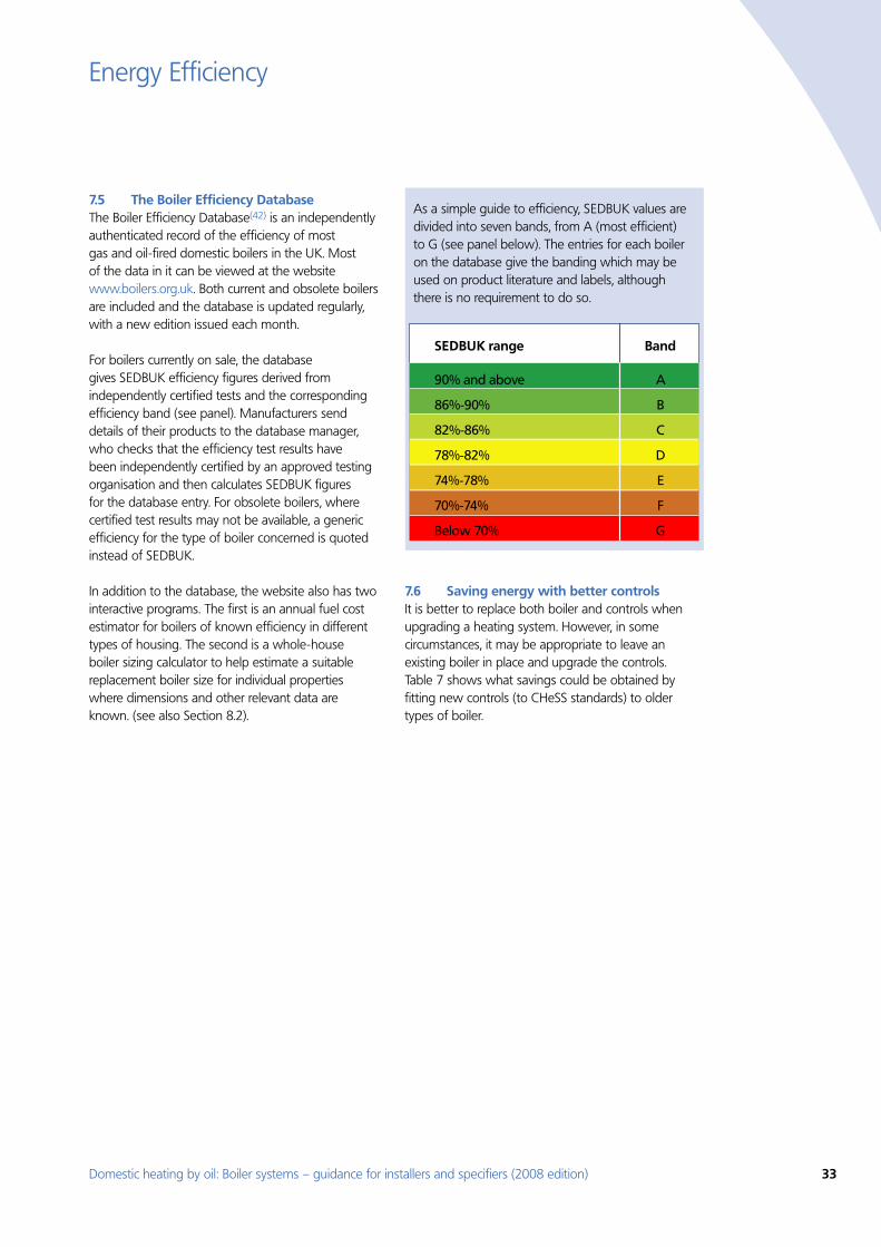
Domestic heating by oil: Boiler systems – guidance for installers and specifiers (2008 edition) 33
Energy Efficiency
The Boiler Efficiency Database 7.5 The Boiler Efficiency Database(42) is an independently authenticated record of the efficiency of most gas and oil-fired domestic boilers in the UK. Most of the data in it can be viewed at the website www.boilers.org.uk. Both current and obsolete boilers are included and the database is updated regularly, with a new edition issued each month.
For boilers currently on sale, the database gives SEDBUK efficiency figures derived from independently certified tests and the corresponding efficiency band (see panel). Manufacturers send details of their products to the database manager, who checks that the efficiency test results have been independently certified by an approved testing organisation and then calculates SEDBUK figures for the database entry. For obsolete boilers, where certified test results may not be available, a generic efficiency for the type of boiler concerned is quoted instead of SEDBUK.
In addition to the database, the website also has two interactive programs. The first is an annual fuel cost estimator for boilers of known efficiency in different types of housing. The second is a whole-house boiler sizing calculator to help estimate a suitable replacement boiler size for individual properties where dimensions and other relevant data are known. (see also Section 8.2).
Saving energy with better controls 7.6 It is better to replace both boiler and controls when upgrading a heating system. However, in some circumstances, it may be appropriate to leave an existing boiler in place and upgrade the controls. Table 7 shows what savings could be obtained by fitting new controls (to CHeSS standards) to older types of boiler.
As a simple guide to efficiency, SEDBUK values are divided into seven bands, from A (most efficient) to G (see panel below). The entries for each boiler on the database give the banding which may be used on product literature and labels, although there is no requirement to do so.
SEDBUK range Band
90% and above A
86%-90% B
82%-86% C
78%-82% D
74%-78% E
70%-74% F
Below 70% G
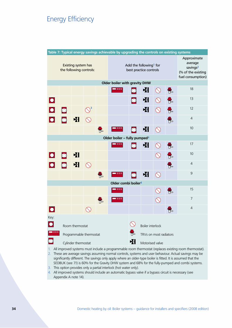
34 Domestic heating by oil: Boiler systems – guidance for installers and specifiers (2008 edition)
Energy Efficiency
Table 7: Typical energy savings achievable by upgrading the controls on existing systems
Existing system has the following controls:
Add the following1 for best practice controls
Approximate average savings2
(% of the existing fuel consumption)
Older boiler with gravity DHW
18
13
3 12
4
10
Older boiler – fully pumped4
17
10
4
9
Older combi boiler4
15
7
4
Key:
Room thermostat
Programmable thermostat
Cylinder thermostat
Boiler interlock
TRVs on most radiators
Motorised valve
1. All improved systems must include a programmable room thermostat (replaces existing room thermostat). 2. These are average savings assuming normal controls, systems and user behaviour. Actual savings may be
significantly different. The savings only apply where an older-type boiler is fitted. It is assumed that the SEDBUK (see 7.1) is 60% for the Gravity DHW system and 68% for the fully-pumped and combi systems.
3. This option provides only a partial interlock (hot water only).4. All improved systems should include an automatic bypass valve if a bypass circuit is necessary (see
Appendix A note 14).
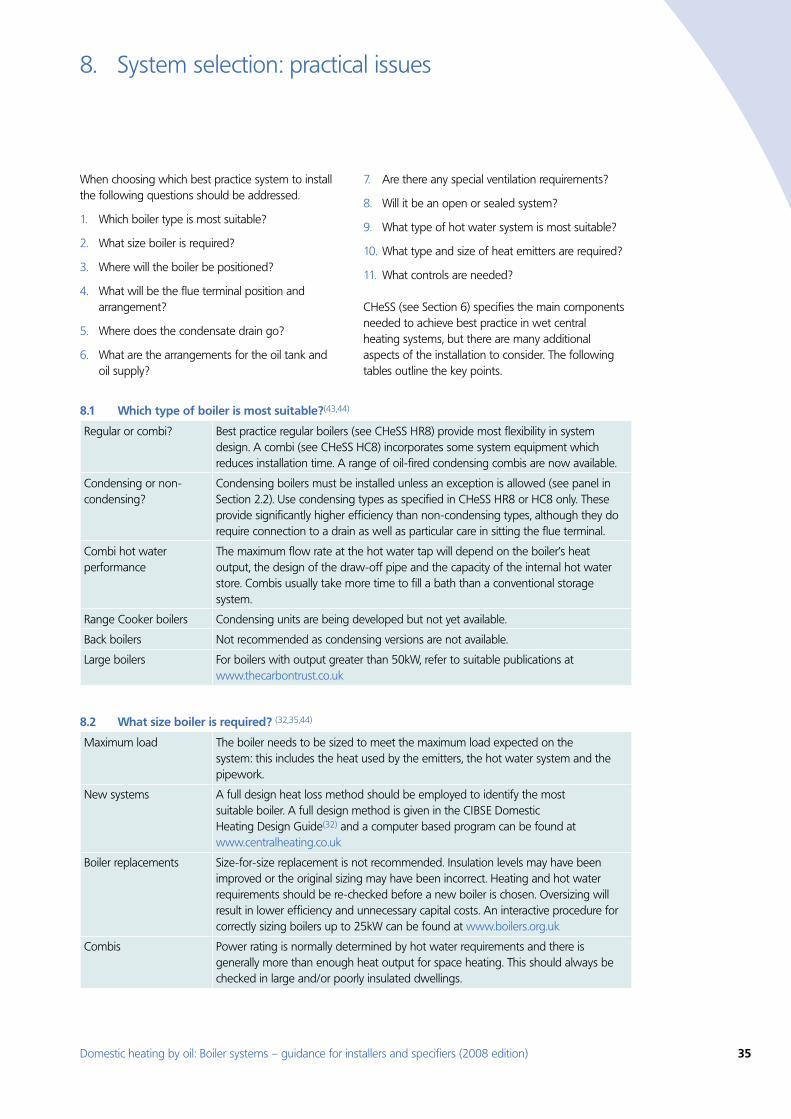
Domestic heating by oil: Boiler systems – guidance for installers and specifiers (2008 edition) 35
System selection: practical issues8.
When choosing which best practice system to install the following questions should be addressed.
1. Which boiler type is most suitable?
2. What size boiler is required?
3. Where will the boiler be positioned?
4. What will be the flue terminal position and arrangement?
5. Where does the condensate drain go?
6. What are the arrangements for the oil tank and oil supply?
7. Are there any special ventilation requirements?
8. Will it be an open or sealed system?
9. What type of hot water system is most suitable?
10. What type and size of heat emitters are required?
11. What controls are needed?
CHeSS (see Section 6) specifies the main components needed to achieve best practice in wet central heating systems, but there are many additional aspects of the installation to consider. The following tables outline the key points.
Which type of boiler is most suitable?8.1 (43,44)
Regular or combi? Best practice regular boilers (see CHeSS HR8) provide most flexibility in system design. A combi (see CHeSS HC8) incorporates some system equipment which reduces installation time. A range of oil-fired condensing combis are now available.
Condensing or non-condensing?
Condensing boilers must be installed unless an exception is allowed (see panel in Section 2.2). Use condensing types as specified in CHeSS HR8 or HC8 only. These provide significantly higher efficiency than non-condensing types, although they do require connection to a drain as well as particular care in sitting the flue terminal.
Combi hot water performance
The maximum flow rate at the hot water tap will depend on the boiler’s heat output, the design of the draw-off pipe and the capacity of the internal hot water store. Combis usually take more time to fill a bath than a conventional storage system.
Range Cooker boilers Condensing units are being developed but not yet available.
Back boilers Not recommended as condensing versions are not available.
Large boilers For boilers with output greater than 50kW, refer to suitable publications at www.thecarbontrust.co.uk
What size boiler is required? 8.2 (32,35,44)
Maximum load The boiler needs to be sized to meet the maximum load expected on the system: this includes the heat used by the emitters, the hot water system and the pipework.
New systems A full design heat loss method should be employed to identify the most suitable boiler. A full design method is given in the CIBSE Domestic Heating Design Guide(32) and a computer based program can be found at www.centralheating.co.uk
Boiler replacements Size-for-size replacement is not recommended. Insulation levels may have been improved or the original sizing may have been incorrect. Heating and hot water requirements should be re-checked before a new boiler is chosen. Oversizing will result in lower efficiency and unnecessary capital costs. An interactive procedure for correctly sizing boilers up to 25kW can be found at www.boilers.org.uk
Combis Power rating is normally determined by hot water requirements and there is generally more than enough heat output for space heating. This should always be checked in large and/or poorly insulated dwellings.
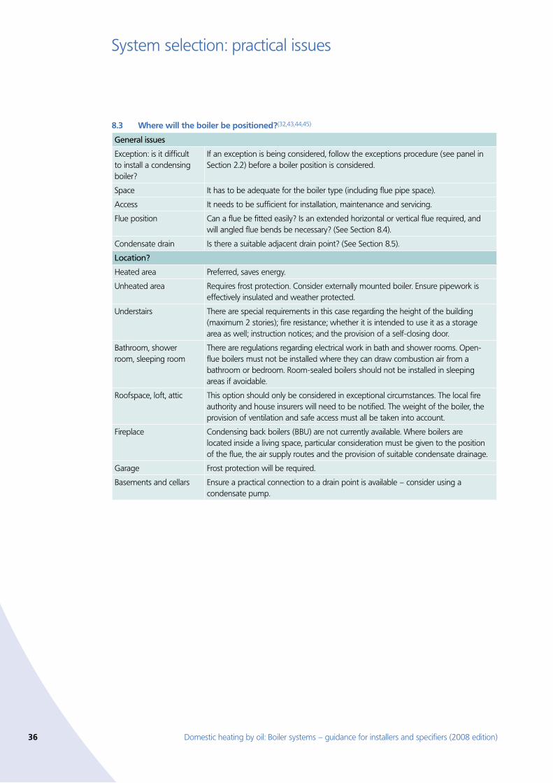
36 Domestic heating by oil: Boiler systems – guidance for installers and specifiers (2008 edition)
System selection: practical issues
Where will the boiler be positioned?8.3 (32,43,44,45)
General issues
Exception: is it difficult to install a condensing boiler?
If an exception is being considered, follow the exceptions procedure (see panel in Section 2.2) before a boiler position is considered.
Space It has to be adequate for the boiler type (including flue pipe space).
Access It needs to be sufficient for installation, maintenance and servicing.
Flue position Can a flue be fitted easily? Is an extended horizontal or vertical flue required, and will angled flue bends be necessary? (See Section 8.4).
Condensate drain Is there a suitable adjacent drain point? (See Section 8.5).
Location?
Heated area Preferred, saves energy.
Unheated area Requires frost protection. Consider externally mounted boiler. Ensure pipework is effectively insulated and weather protected.
Understairs There are special requirements in this case regarding the height of the building (maximum 2 stories); fire resistance; whether it is intended to use it as a storage area as well; instruction notices; and the provision of a self-closing door.
Bathroom, shower room, sleeping room
There are regulations regarding electrical work in bath and shower rooms. Open-flue boilers must not be installed where they can draw combustion air from a bathroom or bedroom. Room-sealed boilers should not be installed in sleeping areas if avoidable.
Roofspace, loft, attic This option should only be considered in exceptional circumstances. The local fire authority and house insurers will need to be notified. The weight of the boiler, the provision of ventilation and safe access must all be taken into account.
Fireplace Condensing back boilers (BBU) are not currently available. Where boilers are located inside a living space, particular consideration must be given to the position of the flue, the air supply routes and the provision of suitable condensate drainage.
Garage Frost protection will be required.
Basements and cellars Ensure a practical connection to a drain point is available – consider using a condensate pump.
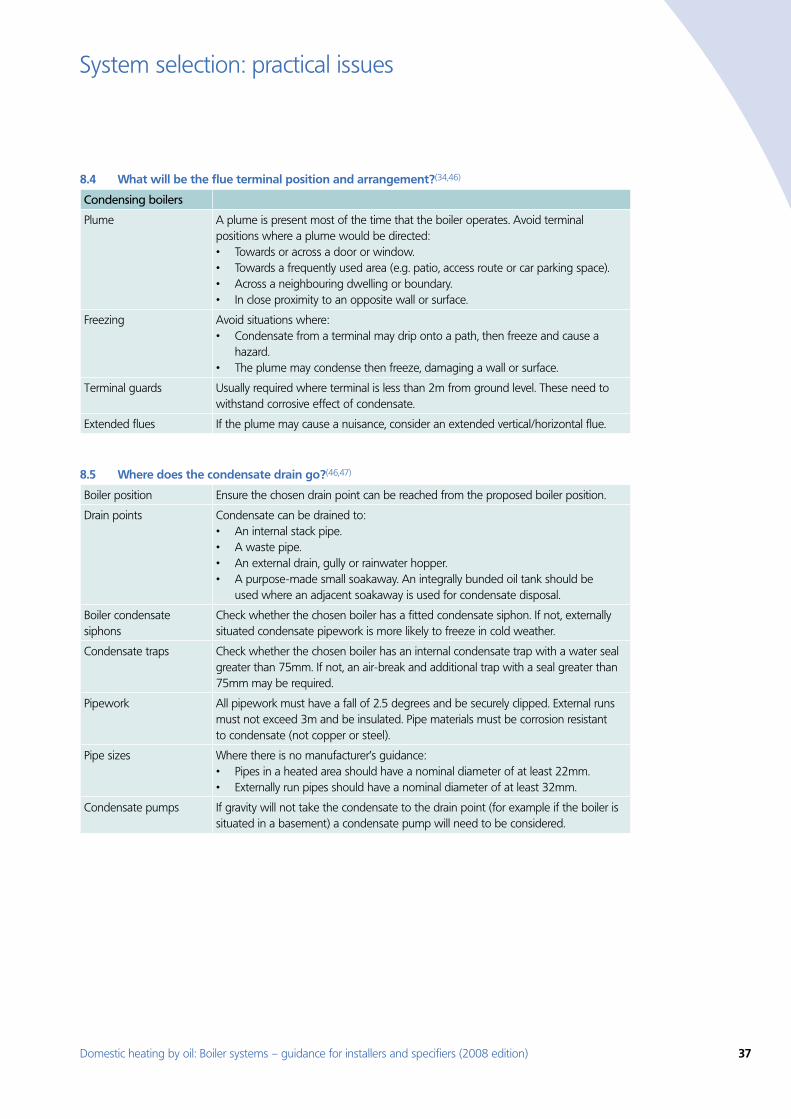
Domestic heating by oil: Boiler systems – guidance for installers and specifiers (2008 edition) 37
System selection: practical issues
What will be the flue terminal position and arrangement?8.4 (34,46)
Condensing boilers
Plume A plume is present most of the time that the boiler operates. Avoid terminal positions where a plume would be directed:
Towards or across a door or window.•Towards a frequently used area (e.g. patio, access route or car parking space).•Across a neighbouring dwelling or boundary.•In close proximity to an opposite wall or surface. •
Freezing Avoid situations where:Condensate from a terminal may drip onto a path, then freeze and cause a •hazard.The plume may condense then freeze, damaging a wall or surface. •
Terminal guards Usually required where terminal is less than 2m from ground level. These need to withstand corrosive effect of condensate.
Extended flues If the plume may cause a nuisance, consider an extended vertical/horizontal flue.
Where does the condensate drain go?8.5 (46,47)
Boiler position Ensure the chosen drain point can be reached from the proposed boiler position.
Drain points Condensate can be drained to:An internal stack pipe.•A waste pipe.•An external drain, gully or rainwater hopper.•A purpose-made small soakaway. An integrally bunded oil tank should be •used where an adjacent soakaway is used for condensate disposal.
Boiler condensate siphons
Check whether the chosen boiler has a fitted condensate siphon. If not, externally situated condensate pipework is more likely to freeze in cold weather.
Condensate traps Check whether the chosen boiler has an internal condensate trap with a water seal greater than 75mm. If not, an air-break and additional trap with a seal greater than 75mm may be required.
Pipework All pipework must have a fall of 2.5 degrees and be securely clipped. External runs must not exceed 3m and be insulated. Pipe materials must be corrosion resistant to condensate (not copper or steel).
Pipe sizes Where there is no manufacturer’s guidance:Pipes in a heated area should have a nominal diameter of at least 22mm.•Externally run pipes should have a nominal diameter of at least 32mm. •
Condensate pumps If gravity will not take the condensate to the drain point (for example if the boiler is situated in a basement) a condensate pump will need to be considered.
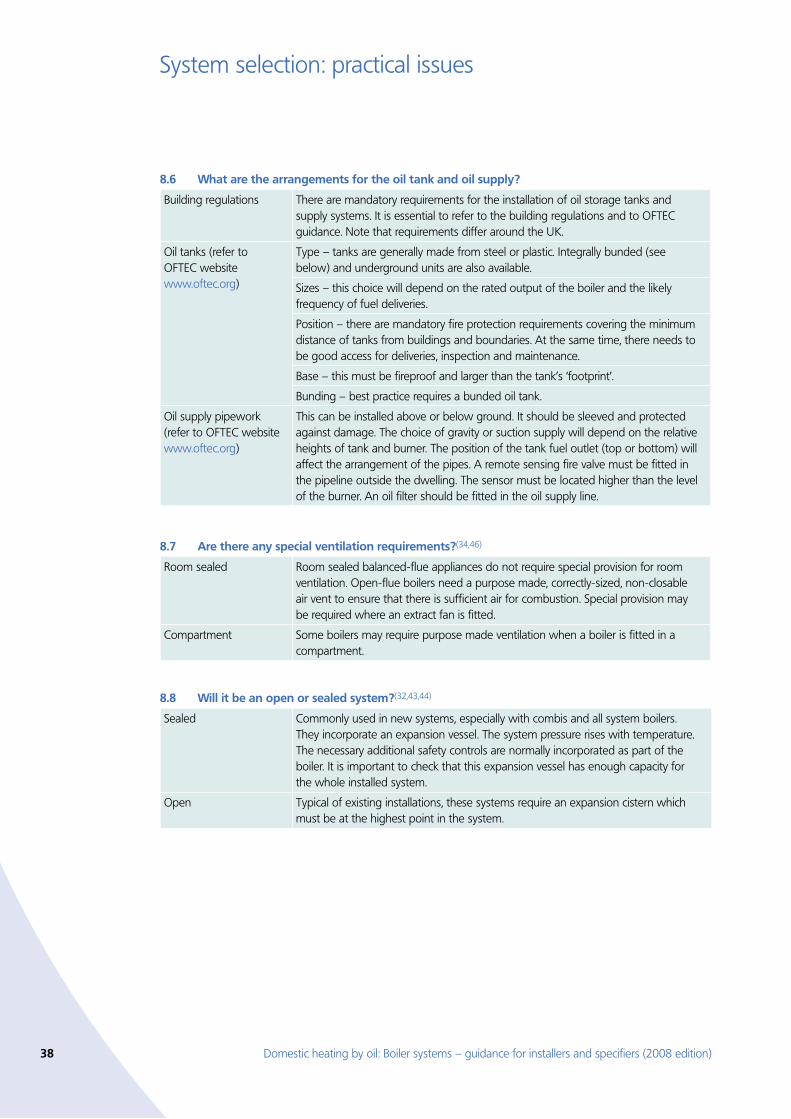
38 Domestic heating by oil: Boiler systems – guidance for installers and specifiers (2008 edition)
System selection: practical issues
What are the arrangements for the oil tank and oil supply? 8.6
Building regulations There are mandatory requirements for the installation of oil storage tanks and supply systems. It is essential to refer to the building regulations and to OFTEC guidance. Note that requirements differ around the UK.
Oil tanks (refer to OFTEC website www.oftec.org)
Type – tanks are generally made from steel or plastic. Integrally bunded (see below) and underground units are also available.
Sizes – this choice will depend on the rated output of the boiler and the likely frequency of fuel deliveries.
Position – there are mandatory fire protection requirements covering the minimum distance of tanks from buildings and boundaries. At the same time, there needs to be good access for deliveries, inspection and maintenance.
Base – this must be fireproof and larger than the tank’s ‘footprint’.
Bunding – best practice requires a bunded oil tank.
Oil supply pipework (refer to OFTEC website www.oftec.org)
This can be installed above or below ground. It should be sleeved and protected against damage. The choice of gravity or suction supply will depend on the relative heights of tank and burner. The position of the tank fuel outlet (top or bottom) will affect the arrangement of the pipes. A remote sensing fire valve must be fitted in the pipeline outside the dwelling. The sensor must be located higher than the level of the burner. An oil filter should be fitted in the oil supply line.
Are there any special ventilation requirements?8.7 (34,46)
Room sealed Room sealed balanced-flue appliances do not require special provision for room ventilation. Open-flue boilers need a purpose made, correctly-sized, non-closable air vent to ensure that there is sufficient air for combustion. Special provision may be required where an extract fan is fitted.
Compartment Some boilers may require purpose made ventilation when a boiler is fitted in a compartment.
Will it be an open or sealed system?8.8 (32,43,44)
Sealed Commonly used in new systems, especially with combis and all system boilers. They incorporate an expansion vessel. The system pressure rises with temperature. The necessary additional safety controls are normally incorporated as part of the boiler. It is important to check that this expansion vessel has enough capacity for the whole installed system.
Open Typical of existing installations, these systems require an expansion cistern which must be at the highest point in the system.
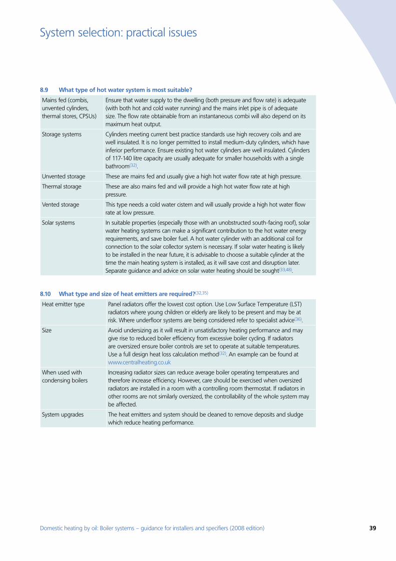
Domestic heating by oil: Boiler systems – guidance for installers and specifiers (2008 edition) 39
System selection: practical issues
What type of hot water system is most suitable? 8.9
Mains fed (combis, unvented cylinders, thermal stores, CPSUs)
Ensure that water supply to the dwelling (both pressure and flow rate) is adequate (with both hot and cold water running) and the mains inlet pipe is of adequate size. The flow rate obtainable from an instantaneous combi will also depend on its maximum heat output.
Storage systems Cylinders meeting current best practice standards use high recovery coils and are well insulated. It is no longer permitted to install medium-duty cylinders, which have inferior performance. Ensure existing hot water cylinders are well insulated. Cylinders of 117-140 litre capacity are usually adequate for smaller households with a single bathroom(32).
Unvented storage These are mains fed and usually give a high hot water flow rate at high pressure.
Thermal storage These are also mains fed and will provide a high hot water flow rate at high pressure.
Vented storage This type needs a cold water cistern and will usually provide a high hot water flow rate at low pressure.
Solar systems In suitable properties (especially those with an unobstructed south-facing roof), solar water heating systems can make a significant contribution to the hot water energy requirements, and save boiler fuel. A hot water cylinder with an additional coil for connection to the solar collector system is necessary. If solar water heating is likely to be installed in the near future, it is advisable to choose a suitable cylinder at the time the main heating system is installed, as it will save cost and disruption later. Separate guidance and advice on solar water heating should be sought(33,48).
What type and size of heat emitters are required?8.10 (32,35)
Heat emitter type Panel radiators offer the lowest cost option. Use Low Surface Temperature (LST) radiators where young children or elderly are likely to be present and may be at risk. Where underfloor systems are being considered refer to specialist advice(36).
Size Avoid undersizing as it will result in unsatisfactory heating performance and may give rise to reduced boiler efficiency from excessive boiler cycling. If radiators are oversized ensure boiler controls are set to operate at suitable temperatures. Use a full design heat loss calculation method(32). An example can be found at www.centralheating.co.uk
When used with condensing boilers
Increasing radiator sizes can reduce average boiler operating temperatures and therefore increase efficiency. However, care should be exercised when oversized radiators are installed in a room with a controlling room thermostat. If radiators in other rooms are not similarly oversized, the controllability of the whole system may be affected.
System upgrades The heat emitters and system should be cleaned to remove deposits and sludge which reduce heating performance.
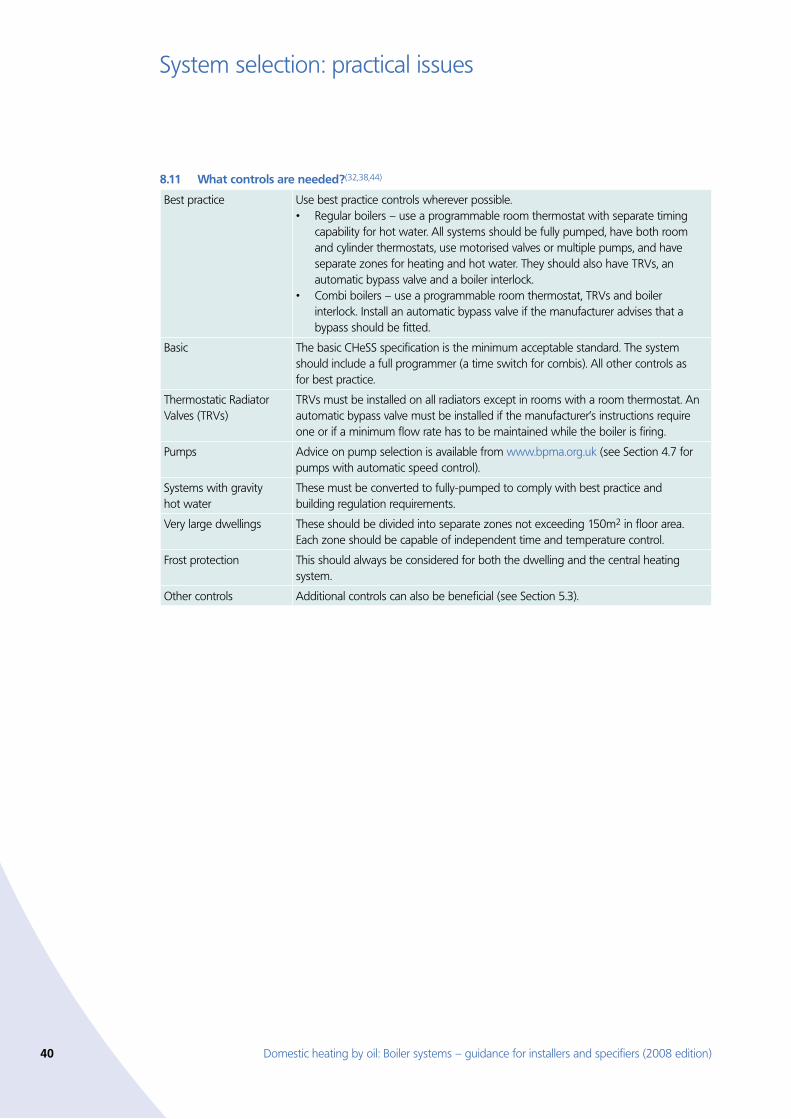
40 Domestic heating by oil: Boiler systems – guidance for installers and specifiers (2008 edition)
System selection: practical issues
What controls are needed?8.11 (32,38,44)
Best practice Use best practice controls wherever possible. Regular boilers – use a programmable room thermostat with separate timing •capability for hot water. All systems should be fully pumped, have both room and cylinder thermostats, use motorised valves or multiple pumps, and have separate zones for heating and hot water. They should also have TRVs, an automatic bypass valve and a boiler interlock. Combi boilers – use a programmable room thermostat, TRVs and boiler •interlock. Install an automatic bypass valve if the manufacturer advises that a bypass should be fitted.
Basic The basic CHeSS specification is the minimum acceptable standard. The system should include a full programmer (a time switch for combis). All other controls as for best practice.
Thermostatic Radiator Valves (TRVs)
TRVs must be installed on all radiators except in rooms with a room thermostat. An automatic bypass valve must be installed if the manufacturer’s instructions require one or if a minimum flow rate has to be maintained while the boiler is firing.
Pumps Advice on pump selection is available from www.bpma.org.uk (see Section 4.7 for pumps with automatic speed control).
Systems with gravity hot water
These must be converted to fully-pumped to comply with best practice and building regulation requirements.
Very large dwellings These should be divided into separate zones not exceeding 150m2 in floor area. Each zone should be capable of independent time and temperature control.
Frost protection This should always be considered for both the dwelling and the central heating system.
Other controls Additional controls can also be beneficial (see Section 5.3).
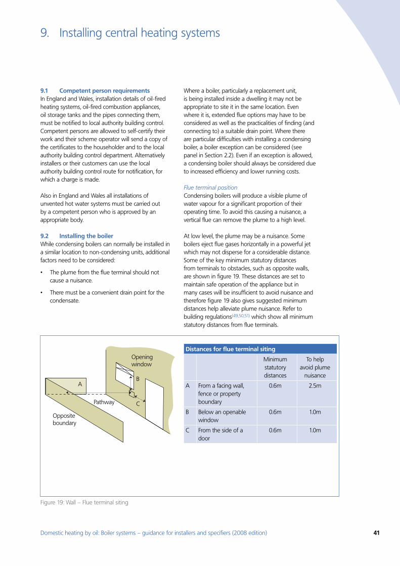
Domestic heating by oil: Boiler systems – guidance for installers and specifiers (2008 edition) 41
Figure 19: Wall – Flue terminal siting
Opening window
Pathway
Oppositeboundary
AB
C
Distances for flue terminal siting
Minimum statutory distances
To help avoid plume
nuisance
A From a facing wall, fence or property boundary
0.6m 2.5m
B Below an openable window
0.6m 1.0m
C From the side of a door
0.6m 1.0m
Installing central heating systems9.
Competent person requirements 9.1 In England and Wales, installation details of oil-fired heating systems, oil-fired combustion appliances, oil storage tanks and the pipes connecting them, must be notified to local authority building control. Competent persons are allowed to self-certify their work and their scheme operator will send a copy of the certificates to the householder and to the local authority building control department. Alternatively installers or their customers can use the local authority building control route for notification, for which a charge is made.
Also in England and Wales all installations of unvented hot water systems must be carried out by a competent person who is approved by an appropriate body.
Installing the boiler 9.2 While condensing boilers can normally be installed in a similar location to non-condensing units, additional factors need to be considered:
The plume from the flue terminal should not •cause a nuisance.
There must be a convenient drain point for the •condensate.
Where a boiler, particularly a replacement unit, is being installed inside a dwelling it may not be appropriate to site it in the same location. Even where it is, extended flue options may have to be considered as well as the practicalities of finding (and connecting to) a suitable drain point. Where there are particular difficulties with installing a condensing boiler, a boiler exception can be considered (see panel in Section 2.2). Even if an exception is allowed, a condensing boiler should always be considered due to increased efficiency and lower running costs.
Flue terminal position Condensing boilers will produce a visible plume of water vapour for a significant proportion of their operating time. To avoid this causing a nuisance, a vertical flue can remove the plume to a high level.
At low level, the plume may be a nuisance. Some boilers eject flue gases horizontally in a powerful jet which may not disperse for a considerable distance. Some of the key minimum statutory distances from terminals to obstacles, such as opposite walls, are shown in figure 19. These distances are set to maintain safe operation of the appliance but in many cases will be insufficient to avoid nuisance and therefore figure 19 also gives suggested minimum distances help alleviate plume nuisance. Refer to building regulations(49,50,51) which show all minimum statutory distances from flue terminals.
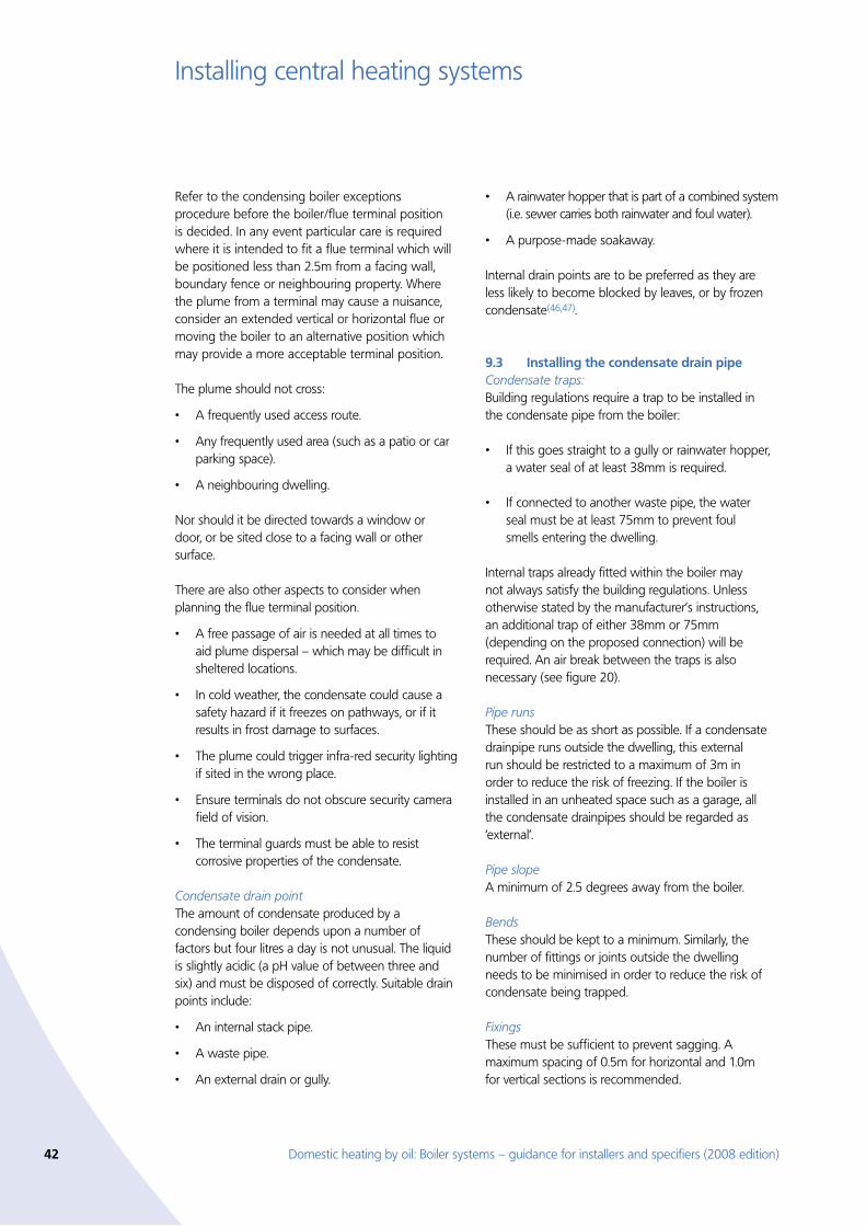
42 Domestic heating by oil: Boiler systems – guidance for installers and specifiers (2008 edition)
Installing central heating systems
Refer to the condensing boiler exceptions procedure before the boiler/flue terminal position is decided. In any event particular care is required where it is intended to fit a flue terminal which will be positioned less than 2.5m from a facing wall, boundary fence or neighbouring property. Where the plume from a terminal may cause a nuisance, consider an extended vertical or horizontal flue or moving the boiler to an alternative position which may provide a more acceptable terminal position.
The plume should not cross:
A frequently used access route.•
Any frequently used area (such as a patio or car •parking space).
A neighbouring dwelling. •
Nor should it be directed towards a window or door, or be sited close to a facing wall or other surface.
There are also other aspects to consider when planning the flue terminal position.
A free passage of air is needed at all times to •aid plume dispersal – which may be difficult in sheltered locations.
In cold weather, the condensate could cause a •safety hazard if it freezes on pathways, or if it results in frost damage to surfaces.
The plume could trigger infra-red security lighting •if sited in the wrong place.
Ensure terminals do not obscure security camera •field of vision.
The terminal guards must be able to resist •corrosive properties of the condensate.
Condensate drain point The amount of condensate produced by a condensing boiler depends upon a number of factors but four litres a day is not unusual. The liquid is slightly acidic (a pH value of between three and six) and must be disposed of correctly. Suitable drain points include:
An internal stack pipe. •
A waste pipe. •
An external drain or gully. •
A rainwater hopper that is part of a combined system •(i.e. sewer carries both rainwater and foul water).
A purpose-made soakaway. •
Internal drain points are to be preferred as they are less likely to become blocked by leaves, or by frozen condensate(46,47).
Installing the condensate drain pipe 9.3 Condensate traps:Building regulations require a trap to be installed in the condensate pipe from the boiler:
If this goes straight to a gully or rainwater hopper, •a water seal of at least 38mm is required.
If connected to another waste pipe, the water •seal must be at least 75mm to prevent foul smells entering the dwelling.
Internal traps already fitted within the boiler may not always satisfy the building regulations. Unless otherwise stated by the manufacturer’s instructions, an additional trap of either 38mm or 75mm (depending on the proposed connection) will be required. An air break between the traps is also necessary (see figure 20).
Pipe runsThese should be as short as possible. If a condensate drainpipe runs outside the dwelling, this external run should be restricted to a maximum of 3m in order to reduce the risk of freezing. If the boiler is installed in an unheated space such as a garage, all the condensate drainpipes should be regarded as ‘external’.
Pipe slopeA minimum of 2.5 degrees away from the boiler.
BendsThese should be kept to a minimum. Similarly, the number of fittings or joints outside the dwelling needs to be minimised in order to reduce the risk of condensate being trapped.
FixingsThese must be sufficient to prevent sagging. A maximum spacing of 0.5m for horizontal and 1.0m for vertical sections is recommended.
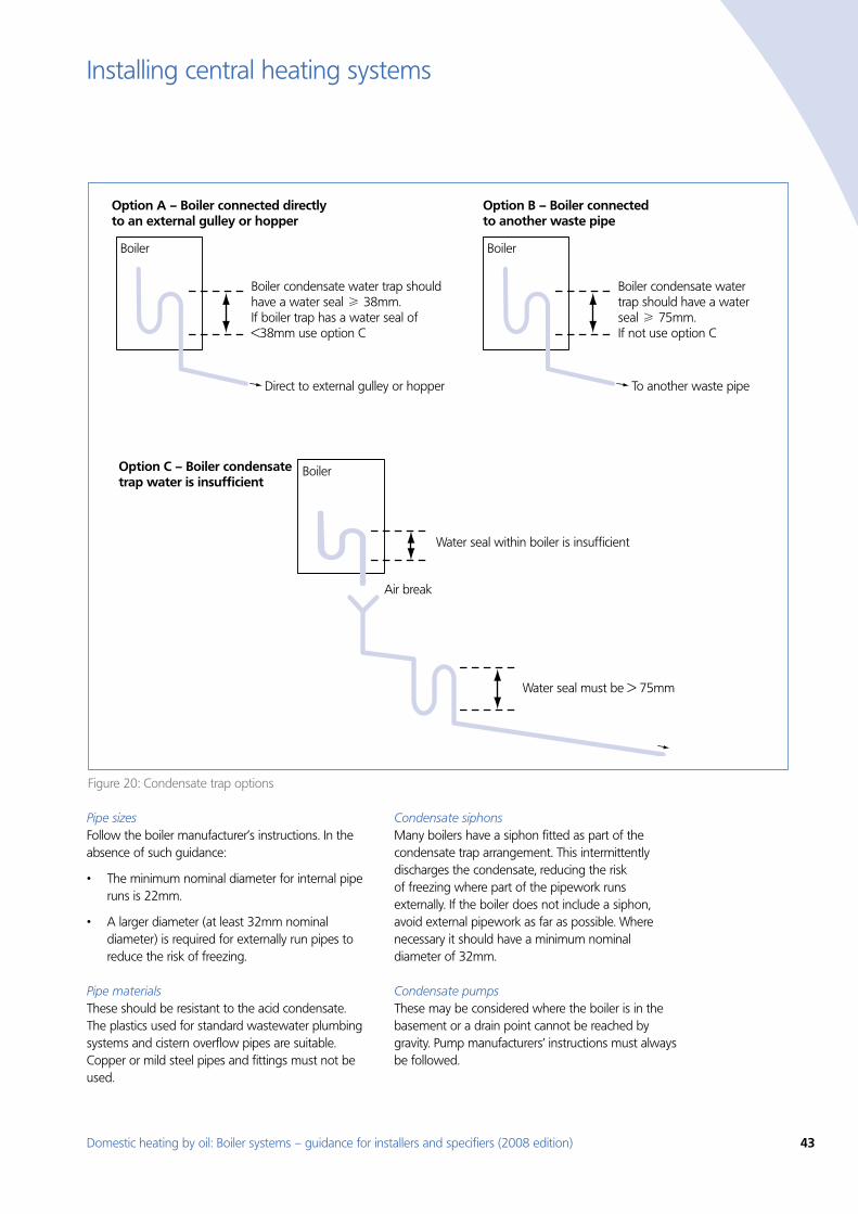
Domestic heating by oil: Boiler systems – guidance for installers and specifiers (2008 edition) 43
Installing central heating systems
Figure 20: Condensate trap options
Boiler
Boiler condensate water trap should have a water seal H 38mm.If boiler trap has a water seal of <38mm use option C
Water seal must be > 75mm
Direct to external gulley or hopper
Option A – Boiler connected directlyto an external gulley or hopper
Boiler
Boiler condensate water trap should have a water seal H 75mm.If not use option C
To another waste pipe
Option B – Boiler connected to another waste pipe
Boiler
Water seal within boiler is insufficient
Air break
Option C – Boiler condensate trap water is insufficient
Pipe sizesFollow the boiler manufacturer’s instructions. In the absence of such guidance:
The minimum nominal diameter for internal pipe •runs is 22mm.
A larger diameter (at least 32mm nominal •diameter) is required for externally run pipes to reduce the risk of freezing.
Pipe materialsThese should be resistant to the acid condensate. The plastics used for standard wastewater plumbing systems and cistern overflow pipes are suitable. Copper or mild steel pipes and fittings must not be used.
Condensate siphonsMany boilers have a siphon fitted as part of the condensate trap arrangement. This intermittently discharges the condensate, reducing the risk of freezing where part of the pipework runs externally. If the boiler does not include a siphon, avoid external pipework as far as possible. Where necessary it should have a minimum nominal diameter of 32mm.
Condensate pumpsThese may be considered where the boiler is in the basement or a drain point cannot be reached by gravity. Pump manufacturers’ instructions must always be followed.
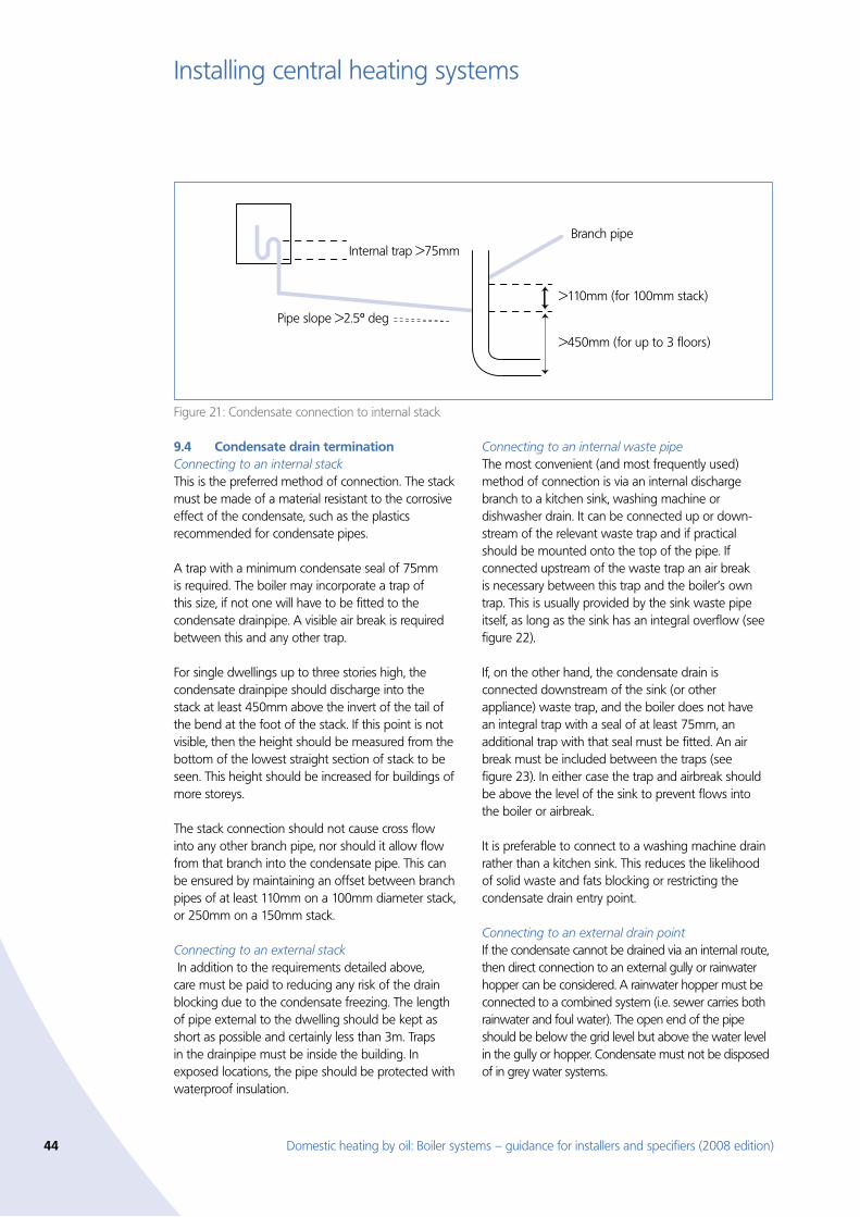
44 Domestic heating by oil: Boiler systems – guidance for installers and specifiers (2008 edition)
Installing central heating systems
Condensate drain termination 9.4 Connecting to an internal stackThis is the preferred method of connection. The stack must be made of a material resistant to the corrosive effect of the condensate, such as the plastics recommended for condensate pipes.
A trap with a minimum condensate seal of 75mm is required. The boiler may incorporate a trap of this size, if not one will have to be fitted to the condensate drainpipe. A visible air break is required between this and any other trap.
For single dwellings up to three stories high, the condensate drainpipe should discharge into the stack at least 450mm above the invert of the tail of the bend at the foot of the stack. If this point is not visible, then the height should be measured from the bottom of the lowest straight section of stack to be seen. This height should be increased for buildings of more storeys.
The stack connection should not cause cross flow into any other branch pipe, nor should it allow flow from that branch into the condensate pipe. This can be ensured by maintaining an offset between branch pipes of at least 110mm on a 100mm diameter stack, or 250mm on a 150mm stack.
Connecting to an external stack In addition to the requirements detailed above, care must be paid to reducing any risk of the drain blocking due to the condensate freezing. The length of pipe external to the dwelling should be kept as short as possible and certainly less than 3m. Traps in the drainpipe must be inside the building. In exposed locations, the pipe should be protected with waterproof insulation.
Connecting to an internal waste pipeThe most convenient (and most frequently used) method of connection is via an internal discharge branch to a kitchen sink, washing machine or dishwasher drain. It can be connected up or down-stream of the relevant waste trap and if practical should be mounted onto the top of the pipe. If connected upstream of the waste trap an air break is necessary between this trap and the boiler’s own trap. This is usually provided by the sink waste pipe itself, as long as the sink has an integral overflow (see figure 22).
If, on the other hand, the condensate drain is connected downstream of the sink (or other appliance) waste trap, and the boiler does not have an integral trap with a seal of at least 75mm, an additional trap with that seal must be fitted. An air break must be included between the traps (see figure 23). In either case the trap and airbreak should be above the level of the sink to prevent flows into the boiler or airbreak.
It is preferable to connect to a washing machine drain rather than a kitchen sink. This reduces the likelihood of solid waste and fats blocking or restricting the condensate drain entry point.
Connecting to an external drain pointIf the condensate cannot be drained via an internal route, then direct connection to an external gully or rainwater hopper can be considered. A rainwater hopper must be connected to a combined system (i.e. sewer carries both rainwater and foul water). The open end of the pipe should be below the grid level but above the water level in the gully or hopper. Condensate must not be disposed of in grey water systems.
Pipe slope >2.5º deg
Internal trap >75mm
>110mm (for 100mm stack)
>450mm (for up to 3 floors)
Branch pipe
Figure 21: Condensate connection to internal stack
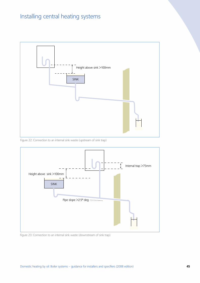
Domestic heating by oil: Boiler systems – guidance for installers and specifiers (2008 edition) 45
Installing central heating systems
Pipe slope >2.5º deg
SINK
Height above sink >100mm
Internal trap >75mm
Figure 22: Connection to an internal sink waste (upstream of sink trap)
SINK
Height above sink >100mm
Figure 23: Connection to an internal sink waste (downstream of sink trap)
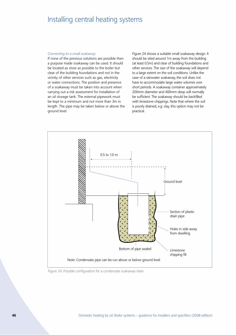
46 Domestic heating by oil: Boiler systems – guidance for installers and specifiers (2008 edition)
Installing central heating systems
Connecting to a small soakawayIf none of the previous solutions are possible then a purpose made soakaway can be used. It should be located as close as possible to the boiler but clear of the building foundations and not in the vicinity of other services such as gas, electricity or water connections. The position and presence of a soakaway must be taken into account when carrying out a risk assessment for installation of an oil storage tank. The external pipework must be kept to a minimum and not more than 3m in length. The pipe may be taken below or above the ground level.
Figure 24 shows a suitable small soakaway design. It should be sited around 1m away from the building (at least 0.5m) and clear of building foundations and other services. The size of the soakaway will depend to a large extent on the soil conditions. Unlike the case of a rainwater soakaway, the soil does not have to accommodate large water volumes over short periods. A soakaway container approximately 200mm diameter and 400mm deep will normally be sufficient. The soakaway should be backfilled with limestone chippings. Note that where the soil is poorly drained, e.g. clay, this option may not be practical.
Figure 24: Possible configuration for a condensate soakaway drain
0.5 to 1.0 m
Note: Condensate pipe can be run above or below ground level
Section of plasticdrain pipe
Holes in side away from dwelling
Ground level
Limestonechipping fill
Bottom of pipe sealed
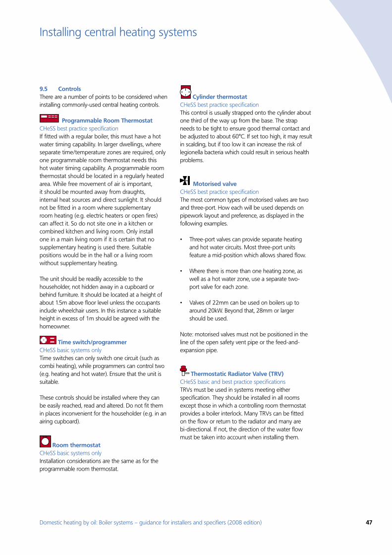
Domestic heating by oil: Boiler systems – guidance for installers and specifiers (2008 edition) 47
Installing central heating systems
Controls9.5 There are a number of points to be considered when installing commonly-used central heating controls.
Programmable Room Thermostat CHeSS best practice specification If fitted with a regular boiler, this must have a hot water timing capability. In larger dwellings, where separate time/temperature zones are required, only one programmable room thermostat needs this hot water timing capability. A programmable room thermostat should be located in a regularly heated area. While free movement of air is important, it should be mounted away from draughts, internal heat sources and direct sunlight. It should not be fitted in a room where supplementary room heating (e.g. electric heaters or open fires) can affect it. So do not site one in a kitchen or combined kitchen and living room. Only install one in a main living room if it is certain that no supplementary heating is used there. Suitable positions would be in the hall or a living room without supplementary heating.
The unit should be readily accessible to the householder, not hidden away in a cupboard or behind furniture. It should be located at a height of about 1.5m above floor level unless the occupants include wheelchair users. In this instance a suitable height in excess of 1m should be agreed with the homeowner.
Time switch/programmer CHeSS basic systems only Time switches can only switch one circuit (such as combi heating), while programmers can control two (e.g. heating and hot water). Ensure that the unit is suitable.
These controls should be installed where they can be easily reached, read and altered. Do not fit them in places inconvenient for the householder (e.g. in an airing cupboard).
Room thermostat CHeSS basic systems only Installation considerations are the same as for the programmable room thermostat.
Cylinder thermostat CHeSS best practice specification This control is usually strapped onto the cylinder about one third of the way up from the base. The strap needs to be tight to ensure good thermal contact and be adjusted to about 60°C. If set too high, it may result in scalding, but if too low it can increase the risk of legionella bacteria which could result in serious health problems.
Motorised valve CHeSS best practice specification The most common types of motorised valves are two and three-port. How each will be used depends on pipework layout and preference, as displayed in the following examples.
Three-port valves can provide separate heating •and hot water circuits. Most three-port units feature a mid-position which allows shared flow.
Where there is more than one heating zone, as •well as a hot water zone, use a separate two-port valve for each zone.
Valves of 22mm can be used on boilers up to •around 20kW. Beyond that, 28mm or larger should be used.
Note: motorised valves must not be positioned in the line of the open safety vent pipe or the feed-and-expansion pipe.
Thermostatic Radiator Valve (TRV) CHeSS basic and best practice specifications TRVs must be used in systems meeting either specification. They should be installed in all rooms except those in which a controlling room thermostat provides a boiler interlock. Many TRVs can be fitted on the flow or return to the radiator and many are bi-directional. If not, the direction of the water flow must be taken into account when installing them.
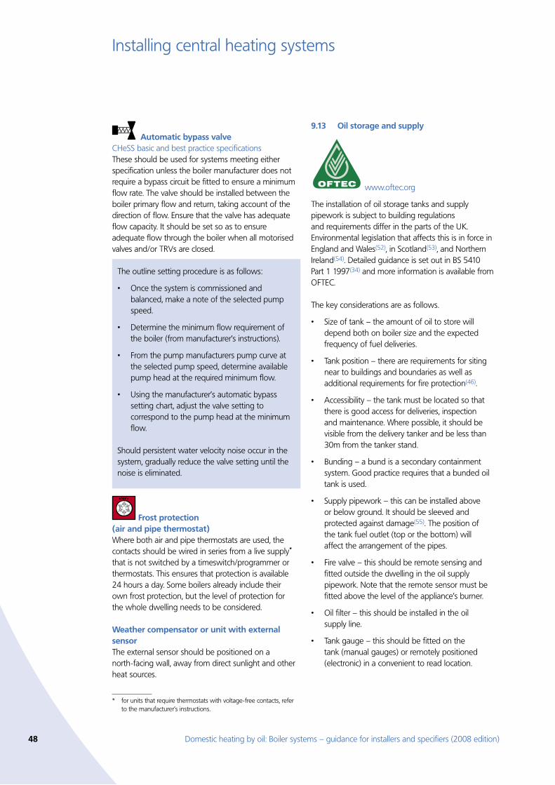
48 Domestic heating by oil: Boiler systems – guidance for installers and specifiers (2008 edition)
Installing central heating systems
Automatic bypass valve CHeSS basic and best practice specifications These should be used for systems meeting either specification unless the boiler manufacturer does not require a bypass circuit be fitted to ensure a minimum flow rate. The valve should be installed between the boiler primary flow and return, taking account of the direction of flow. Ensure that the valve has adequate flow capacity. It should be set so as to ensure adequate flow through the boiler when all motorised valves and/or TRVs are closed.
Frost protection
(air and pipe thermostat) Where both air and pipe thermostats are used, the contacts should be wired in series from a live supply* that is not switched by a timeswitch/programmer or thermostats. This ensures that protection is available 24 hours a day. Some boilers already include their own frost protection, but the level of protection for the whole dwelling needs to be considered.
Weather compensator or unit with external sensor The external sensor should be positioned on a north-facing wall, away from direct sunlight and other heat sources.
* for units that require thermostats with voltage-free contacts, refer to the manufacturer’s instructions.
Oil storage and supply 9.13
www.oftec.org
The installation of oil storage tanks and supply pipework is subject to building regulations and requirements differ in the parts of the UK. Environmental legislation that affects this is in force in England and Wales(52), in Scotland(53), and Northern Ireland(54). Detailed guidance is set out in BS 5410 Part 1 1997(34) and more information is available from OFTEC.
The key considerations are as follows.
Size of tank – the amount of oil to store will •depend both on boiler size and the expected frequency of fuel deliveries.
Tank position – there are requirements for siting •near to buildings and boundaries as well as additional requirements for fire protection(46).
Accessibility – the tank must be located so that •there is good access for deliveries, inspection and maintenance. Where possible, it should be visible from the delivery tanker and be less than 30m from the tanker stand.
Bunding – a bund is a secondary containment •system. Good practice requires that a bunded oil tank is used.
Supply pipework – this can be installed above •or below ground. It should be sleeved and protected against damage(55). The position of the tank fuel outlet (top or the bottom) will affect the arrangement of the pipes.
Fire valve – this should be remote sensing and •fitted outside the dwelling in the oil supply pipework. Note that the remote sensor must be fitted above the level of the appliance’s burner.
Oil filter – this should be installed in the oil •supply line.
Tank gauge – this should be fitted on the •tank (manual gauges) or remotely positioned (electronic) in a convenient to read location.
The outline setting procedure is as follows:
Once the system is commissioned and •balanced, make a note of the selected pump speed.
Determine the minimum flow requirement of •the boiler (from manufacturer’s instructions).
From the pump manufacturers pump curve at •the selected pump speed, determine available pump head at the required minimum flow.
Using the manufacturer’s automatic bypass •setting chart, adjust the valve setting to correspond to the pump head at the minimum flow.
Should persistent water velocity noise occur in the system, gradually reduce the valve setting until the noise is eliminated.
Domestic heating by oil: Boiler systems – guidance for installers and specifiers (2008 edition) 49
Installing central heating systems
Water treatment 9.14 Effective water treatment of a central heating system is essential to ensure continued efficient and trouble free operation.
Key points are:
Both new and existing systems should be •thoroughly cleaned and flushed out before a new boiler is fitted.
A suitable corrosion inhibitor should be used •in the boiler primary water circuit to minimise corrosion and the formation of scale and sludge.
The water supply may require softening to •prevent scaling of heat exchangers. This is
particularly important in the case of water heaters which are installed in hard water areas (where the water hardness exceeds 200 parts per million. See BS 7593:2006(57)).
Always refer to boiler manufacturer’s •instructions to ensure appropriate cleaning , softening and inhibitor products are used and any special requirements for particular models are applied.
A system with excessive hardness scale and •sludge will not operate at optimal efficiency.
More advice is available on water treatment, the need for it, methods and dealing with problems(56,57).
50 Domestic heating by oil: Boiler systems – guidance for installers and specifiers (2008 edition)
Commissioning and handover10.
Commissioning 10.1 For safe and energy-efficient operation, all parts of a new central heating and hot water system need to be checked to ensure they are working properly. In particular:
The boiler and system should be cleaned •using a recognised flushing procedure (see BS 7593:2006).
A suitable corrosion inhibitor should be used •in the boiler primary water circuit to minimise corrosion and the formation of scale and sludge (subject to recommendation by the boiler manufacturer).
The burner should be adjusted for optimum •combustion and thereby maximum efficiency.
The key system components such as gauges, •valves, fire valves, burner and system controls must be checked for correct and safe operation.
Controls should be set to their optimum settings.•
The customer should be instructed on how to •operate the controls, and the importance of regularly servicing the system needs to be made clear.
In England and Wales, competent persons who carry out this work must send details to their scheme operator who will send certificates to the householder and the local authority building control. Alternatively installers or their customers can use the local authority Building Control route for notification. Suitable documentary evidence must be provided; examples are OFTEC forms for Installation CD/10(58) and Commissioning CD/11(59).
The householder should retain evidence of correct installation, commissioning and servicing of the boiler and systems.
Advising householders 10.2 Installers must instruct the householder how to set and use the controls properly and effectively. In particular, the operation of programmers can be difficult to understand and homeowners will gain little or no benefit from an incorrectly set device. In fact, they will probably end up wasting energy.
As a bare minimum, the manufacturer’s instructions should be left with the householder. However, it will usually be necessary to demonstrate:
How to set the programmer clock and adjust for •GMT and BST.
The use of the time control override function. •
How to set summer hot water only. •
How to separate space heating and domestic hot •water time settings (regular boilers only).
How to set room and cylinder thermostats. •
How to set TRVs. •
The installer will also need to explain:
The function of room thermostats and TRVs, and •the need to set them carefully to avoid wasteful heating. They should only be altered when the needs of the household change, and should not be treated as on/off switches. (e.g, that they should be left alone once set, rather than used as on/off switches).
That the cylinder thermostat needs to be left at •approximately 60°C, since setting it higher may result in scalding while setting it lower can allow the growth of legionella bacteria.
That the radiator lockshield and automatic bypass •valve should not be adjusted once set by the installer.
Why it is best to switch space and water heating •off when not required.
Why it is best to turn the room thermostat down •to frost protection levels (approximately 12°C) unless a separate frost protection system has been fitted.
That sealed boiler systems must have adequate •system pressure and what to do if re-pressurising is needed.
Operational and safety aspects of the oil storage •and supply system, including how to use the tank contents gauge, and the necessary arrangements for re-filling.
Domestic heating by oil: Boiler systems – guidance for installers and specifiers (2008 edition) 51
Commissioning and handover
Servicing 10.3 Users should be made aware of the importance of regular servicing, both of the boiler and the system as a whole (including the oil supply system). This will help maintain its safety and efficiency. In particular, users should consider taking out a regular service contract where a competent service engineer (e.g. registered with OFTEC) will clean and maintain the boiler as well as checking the operation of the system and controls.
Note that homeowners in England and Wales can now ask for an energy rating for their boiler with advice on how to cut fuel bills, whenever an engineer makes a regular service visit. An example of the form used in shown in Appendix D.
52 Domestic heating by oil: Boiler systems – guidance for installers and specifiers (2008 edition)
Appendix A – Notes to CHeSS 2008
CHeSS is published in full as reference(38) and part of it is reproduced here in Section 6. The Notes below apply to CHeSS HR7, HC7, HR8, HC8 (Year 2008).
1. Other componentsThe specifications list only the principal components of a heating system affecting energy efficiency. Other components will be required, such as radiators, circulator pumps (see note 4), cisterns (feed and expansion tanks), and motorised valves. All components must be selected and sized correctly.
2. Design, installation and commissioningHeating systems should be designed to match the heating needs of the buildings in which they are installed, using methods such as those described in Ref [5]. They should be installed in accordance with relevant safety regulations, manufacturers’ instructions, the Benchmark scheme (see Ref [10]), building regulations (see Refs [1], [2], [11]), the Domestic Heating Compliance Guide (see Ref [16]), and British Standards (see Refs [12], [13], [17], [18]). For oil boilers the OFTEC forms CD/10 and CD/11 (or similar) for installation and commissioning should be completed. More detailed advice on domestic wet central heating systems is given in the Energy Saving Trust guides (see Refs [3] and [4]), and the CIBSE guide (see Ref [5]). Commissioning and handover of information on operation and maintenance is a requirement of building regulations and a suitable commissioning certificate should be issued.
3. Water treatmentWater treatment is important as it prolongs effective and trouble-free operation. Three types of water treatment should be considered:
• Cleaningandflushingofthesystembeforeuse
• Corrosioninhibition
• Softeningofthewatersupplytocombiboilersforhot water service in hard water areas.
In each case the recommendation of the boiler manufacturer must be followed as damage may be caused by unsuitable treatment. For both new and replacement systems, thorough cleaning is essential. When a boiler is replaced it is essential to drain and flush all old water from the system in case it contains a corrosion inhibitor unsuitable for the new boiler. Advice on the need for treatment and on causes of problems is given in BS 7593 (see Ref [14]).
4. Circulator pumpAdvice on pump dimensioning is available from the BPMA (British Pump Manufacturers’ Association) website at www.bpma.org.ukPumps installed separately from the boiler (not supplied as part of the boiler unit) which have automatic speed control should not be used in heating systems with TRVs unless the design of the pump and system ensures that the minimum flow rate through the boiler (as specified by the boiler manufacturer) is certain to be maintained under all conditions.
5. Boiler size and typeThe whole house boiler sizing method for houses and flats gives guidance on boiler size and is available on the Energy Saving Trust website at www.energysavingtrust.org.uk/housingbuildings/calculators/boilersizing
A regular boiler does not have the capability to provide domestic hot water directly, though it may do so indirectly via a separate hot water store.
A combination (combi) boiler does have the capability to provide domestic hot water directly, and some models contain an internal hot water store.
A combined primary storage unit (CPSU) is a boiler with a burner that heats a thermal store directly.
Each of these may be either a condensing or non-condensing boiler, and condensing boilers are always more efficient. Condensing boilers are fitted with a drain to dispose of the liquid condensate. Building regulations require all new gas and oil boilers to be condensing, whether installed in new or existing housing, unless there are exceptional circumstances that would make the installation impractical or excessively costly. All boilers in the CHeSS specifications HR7, HC7, HR8 and HC8 are condensing boilers.
For further definitions of boiler types see Appendix D of Ref [6].
6. Boiler efficiencySEDBUK (Seasonal Efficiency of Domestic Boilers in the UK) is the preferred measure of the seasonal efficiency of a boiler installed in typical domestic conditions in the UK, and is used in SAP assessments and the building regulations. The SEDBUK efficiency of most current and obsolete boilers can be found on the website
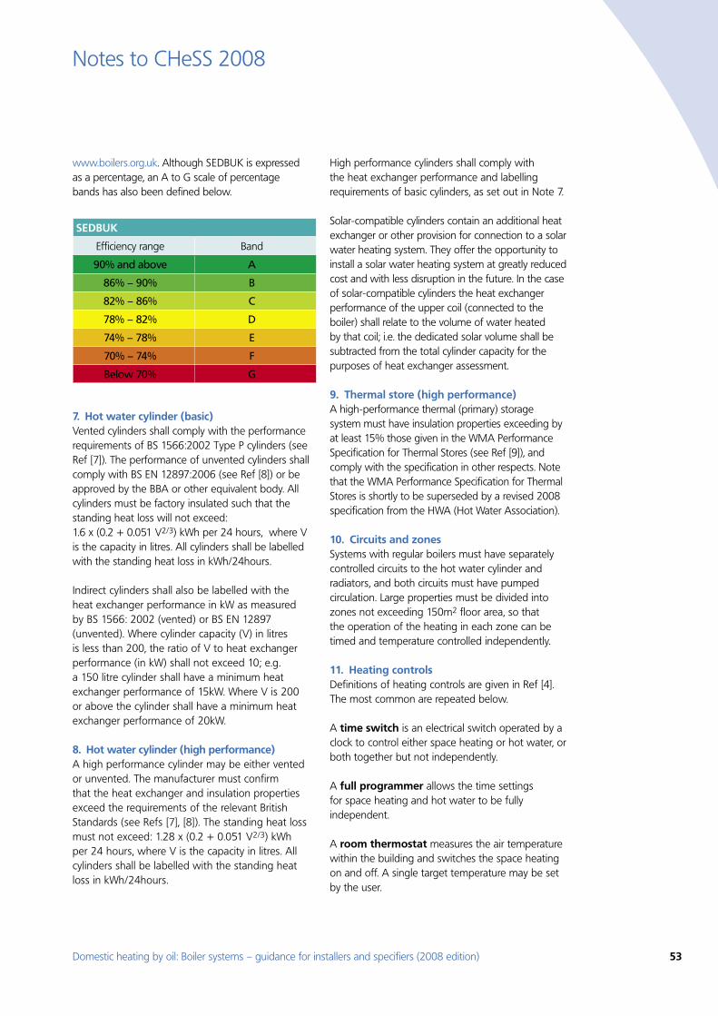
Domestic heating by oil: Boiler systems – guidance for installers and specifiers (2008 edition) 53
Notes to CHeSS 2008
www.boilers.org.uk. Although SEDBUK is expressed as a percentage, an A to G scale of percentage bands has also been defined below.
SEDBUK
Efficiency range Band
90% and above A
86% – 90% B
82% – 86% C
78% – 82% D
74% – 78% E
70% – 74% F
Below 70% G
7. Hot water cylinder (basic)Vented cylinders shall comply with the performance requirements of BS 1566:2002 Type P cylinders (see Ref [7]). The performance of unvented cylinders shall comply with BS EN 12897:2006 (see Ref [8]) or be approved by the BBA or other equivalent body. All cylinders must be factory insulated such that the standing heat loss will not exceed: 1.6 x (0.2 + 0.051 V2/3) kWh per 24 hours, where V is the capacity in litres. All cylinders shall be labelled with the standing heat loss in kWh/24hours.
Indirect cylinders shall also be labelled with the heat exchanger performance in kW as measured by BS 1566: 2002 (vented) or BS EN 12897 (unvented). Where cylinder capacity (V) in litres is less than 200, the ratio of V to heat exchanger performance (in kW) shall not exceed 10; e.g. a 150 litre cylinder shall have a minimum heat exchanger performance of 15kW. Where V is 200 or above the cylinder shall have a minimum heat exchanger performance of 20kW.
8. Hot water cylinder (high performance)A high performance cylinder may be either vented or unvented. The manufacturer must confirm that the heat exchanger and insulation properties exceed the requirements of the relevant British Standards (see Refs [7], [8]). The standing heat loss must not exceed: 1.28 x (0.2 + 0.051 V2/3) kWh per 24 hours, where V is the capacity in litres. All cylinders shall be labelled with the standing heat loss in kWh/24hours.
High performance cylinders shall comply with the heat exchanger performance and labelling requirements of basic cylinders, as set out in Note 7.
Solar-compatible cylinders contain an additional heat exchanger or other provision for connection to a solar water heating system. They offer the opportunity to install a solar water heating system at greatly reduced cost and with less disruption in the future. In the case of solar-compatible cylinders the heat exchanger performance of the upper coil (connected to the boiler) shall relate to the volume of water heated by that coil; i.e. the dedicated solar volume shall be subtracted from the total cylinder capacity for the purposes of heat exchanger assessment.
9. Thermal store (high performance)A high-performance thermal (primary) storage system must have insulation properties exceeding by at least 15% those given in the WMA Performance Specification for Thermal Stores (see Ref [9]), and comply with the specification in other respects. Note that the WMA Performance Specification for Thermal Stores is shortly to be superseded by a revised 2008 specification from the HWA (Hot Water Association).
10. Circuits and zonesSystems with regular boilers must have separately controlled circuits to the hot water cylinder and radiators, and both circuits must have pumped circulation. Large properties must be divided into zones not exceeding 150m2 floor area, so that the operation of the heating in each zone can be timed and temperature controlled independently.
11. Heating controls Definitions of heating controls are given in Ref [4]. The most common are repeated below.
A time switch is an electrical switch operated by a clock to control either space heating or hot water, or both together but not independently.
A full programmer allows the time settings for space heating and hot water to be fully independent.
A room thermostat measures the air temperature within the building and switches the space heating on and off. A single target temperature may be set by the user.
54 Domestic heating by oil: Boiler systems – guidance for installers and specifiers (2008 edition)
Notes to CHeSS 2008
A programmable room thermostat is a combined time switch and room thermostat that allows the user to set different periods with different target temperatures for space heating, usually in a weekly cycle. Some models also allow time control of hot water, therefore replacing a full programmer.
A cylinder thermostat measures the temperature of the hot water cylinder and switches the water heating on and off.
A thermostatic radiator valve (TRV) has an air temperature sensor which is used to control the heat output from the radiator by adjusting water flow.
12. Wireless controls Wireless controls are susceptible to radio transmissions and should therefore be designed to a satisfactory level of immunity, otherwise they may become unreliable as nearby frequency bands become increasingly utilised by communication services.
Compliance with the essential requirements of the European Radio and Telecommunications Terminal Equipment (RTTE) Directive 1999/5/EC is insufficient, as the directive is designed only to ensure that wireless products do not cause harmful interference to other transmissions. It does not give any assurance that the product has a satisfactory level of immunity to interference from other radio transmissions.
Consequently it is not sufficient for the manufacturer to confirm compliance with the RTTE Directive. The manufacturer should also confirm that the switching range, and preferably alignment range, do not include any frequencies below 430MHz, and that in regard to ETSI EN 300 220-1 v1.3.1 (see Ref [15]) the
receiver classification (clause 4.1.1) is either Class 1 or Class 2, and the device is marked in accordance with clause 4.3.4.
13. Boiler interlock Boiler interlock is not a physical device but an arrangement of the system controls (room thermostats, programmable room thermostats, cylinder thermostats, programmers and time switches) so as to ensure that the boiler does not fire when there is no demand for heat.
In a system with a combi boiler this can be achieved by fitting a room thermostat. In a system with a regular boiler this can be achieved by correct wiring interconnection of the room thermostat, cylinder thermostat, and motorised valve(s). It may also be achieved by more advanced controls, such as a boiler energy manager. TRVs alone are not sufficient for boiler interlock.
14. An automatic bypass valve An automatic bypass valve controls water flow in accordance with the water pressure across it, and is used to maintain a minimum flow rate through the boiler and to limit circulation pressure when alternative water paths are closed.
A bypass circuit must be installed if the boiler manufacturer requires one, or specifies that a minimum flow rate has to be maintained while the boiler is firing. The installed bypass circuit must then include an automatic bypass valve (not a fixed-position valve).
Care must be taken to set up the automatic bypass valve correctly, in order to achieve the minimum flow rate required (but not more) when alternative water paths are closed.
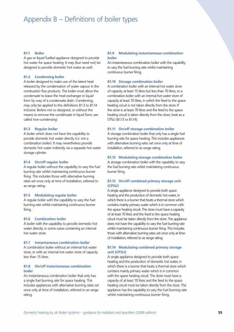
Domestic heating by oil: Boiler systems – guidance for installers and specifiers (2008 edition) 55
B1.1 BoilerA gas or liquid fuelled appliance designed to provide hot water for space heating. It may (but need not) be designed to provide domestic hot water as well.
B1.2 Condensing boilerA boiler designed to make use of the latent heat released by the condensation of water vapour in the combustion flue products. The boiler must allow the condensate to leave the heat exchanger in liquid form by way of a condensate drain. Condensing may only be applied to the definitions B1.3 to B1.14 inclusive. Boilers not so designed, or without the means to remove the condensate in liquid form, are called ‘non-condensing’.
B1.3 Regular boilerA boiler which does not have the capability to provide domestic hot water directly (i.e. not a combination boiler). It may nevertheless provide domestic hot water indirectly via a separate hot water storage cylinder.
B1.4 On/off regular boilerA regular boiler without the capability to vary the fuel burning rate whilst maintaining continuous burner firing. This includes those with alternative burning rates set once only at time of installation, referred to as range rating.
B1.5 Modulating regular boilerA regular boiler with the capability to vary the fuel burning rate whilst maintaining continuous burner firing.
B1.6 Combination boilerA boiler with the capability to provide domestic hot water directly, in some cases containing an internal hot water store.
B1.7 Instantaneous combination boilerA combination boiler without an internal hot water store, or with an internal hot water store of capacity less than 15 litres.
B1.8 On/off instantaneous combination boilerAn instantaneous combination boiler that only has a single fuel burning rate for space heating. This includes appliances with alternative burning rates set once only at time of installation, referred to as range rating.
B1.9 Modulating instantaneous combination boilerAn instantaneous combination boiler with the capability to vary the fuel burning rate whilst maintaining continuous burner firing.
B1.10 Storage combination boilerA combination boiler with an internal hot water store of capacity at least 15 litres but less than 70 litres, or a combination boiler with an internal hot water store of capacity at least 70 litres, in which the feed to the space heating circuit is not taken directly from the store. If the store is at least 70 litres and the feed to the space heating circuit is taken directly from the store, treat as a CPSU (B1.13 or B1.14).
B1.11 On/off storage combination boilerA storage combination boiler that only has a single fuel burning rate for space heating. This includes appliances with alternative burning rates set once only at time of installation, referred to as range rating.
B1.12 Modulating storage combination boilerA storage combination boiler with the capability to vary the fuel burning rate whilst maintaining continuous burner firing.
B1.13 On/off combined primary storage unit (CPSU)A single appliance designed to provide both space heating and the production of domestic hot water, in which there is a burner that heats a thermal store which contains mainly primary water which is in common with the space heating circuit. The store must have a capacity of at least 70 litres and the feed to the space heating circuit must be taken directly from the store. The appliance does not have the capability to vary the fuel burning rate whilst maintaining continuous burner firing. This includes those with alternative burning rates set once only at time of installation, referred to as range rating.
B1.14 Modulating combined primary storage unit (CPSU)A single appliance designed to provide both space heating and the production of domestic hot water, in which there is a burner that heats a thermal store which contains mainly primary water which is in common with the space heating circuit. The store must have a capacity of at least 70 litres and the feed to the space heating circuit must be taken directly from the store. The appliance has the capability to vary the fuel burning rate whilst maintaining continuous burner firing.
Appendix B – Definitions of boiler types
56 Domestic heating by oil: Boiler systems – guidance for installers and specifiers (2008 edition)
Definitions of boiler types
B1.15 Low temperature boilerA non-condensing boiler designed as a low temperature boiler and tested as a low temperature boiler as prescribed by the Boiler Efficiency Directive (i.e. the part load test was carried out at average boiler temperature of 40°C).
B1.16 Keep-hot facilityA facility within an instantaneous combination boiler whereby water within the boiler may be kept hot while there is no demand. The water is kept hot either (i) solely by burning fuel, or (ii) by electricity, or (iii) both by burning fuel and by electricity, though not necessarily simultaneously.
Domestic heating by oil: Boiler systems – guidance for installers and specifiers (2008 edition) 57
Appendix C – Definitions of heating controls
As given in SAP Appendix D(22) the list of definitions has been discussed and agreed with industry representatives, and, for completeness, includes some controls for heating systems other than gas central heating.
Automatic bypass valve A valve to control water flow, operated by the water pressure across it. It is commonly used to maintain a minimum flow rate through a boiler and to limit circulation pressure when alternative water paths are closed (particularly in systems with TRVs).
Boiler anti-cycling device A device to introduce a time delay between boiler firing. Any energy saving is due to a reduction in performance of the heating system. The device does not provide boiler interlock.
Boiler auto ignition An electrically controlled device to ignite the boiler at the start of each firing, avoiding use of a permanent pilot flame.
Boiler energy manager No agreed definition, but typically a device intended to improve boiler control using a selection of features such as weather compensation, load compensation, optimum start control, night setback, frost protection, anticycling control and hot water override.
Boiler interlock This is not a physical device but an arrangement of the system controls so as to ensure that the boiler does not fire when there is no demand for heat. In a system with a combi boiler it can be achieved by fitting a room thermostat. In a system with a regular boiler it can be achieved by correct wiring interconnections between the room thermostat, cylinder thermostat, and motorised valve(s). It may also be achieved by a suitable boiler energy manager.
Boiler modulator (air temperature) A device, or feature within a device, to vary the fuel burning rate of a boiler according to measured room temperature. The boiler under control must have modulating capability and a suitable interface for connection.
Boiler modulator (water temperature) A device, or feature within a device, to vary the fuel burning rate of a boiler according to measured water temperature. It is often fitted within the boiler casing. The boiler under control must have modulating capability.
Boiler thermostat A thermostat within the boiler casing to limit the temperature of water passing through the boiler by switching off the boiler. The target temperature may either be fixed or set by the user.
CELECT-type electric heating control Integrated central control system for electric storage and panel heaters that provides programmed space temperatures at different times of the day for a number of separate heating zones in the dwelling. It minimises the charge period of the storage heaters according to the external temperature.
Cylinder thermostat A sensing device to measure the temperature of the hot water cylinder and switch on and off the water heating. A single target temperature may be set by the user.
Delayed start A device, or feature within a device, to delay the chosen starting time for space heating according to the temperature measured inside or outside the building.
Frost thermostat A device to detect low air temperature and switch on heating to avoid frost damage, arranged to override other controls.
Load compensator A device, or feature within a device, which adjusts the temperature of the water circulating through the heating system according to the temperature measured inside the building.
Motorised valve A valve to control water flow, operated electrically. A two-port motorised valve controls water flow to a single destination. A three-port motorised valve controls water flow to two destinations (usually for space heating and hot water), and may be either a diverter valve (only one outlet open at a time) or a mid-position valve (either one, or both, outlets open at a time). The valve movement may also open or close switches, which are used to control the boiler and pump.
58 Domestic heating by oil: Boiler systems – guidance for installers and specifiers (2008 edition)
Definitions of heating controls
Night setback A feature of a room thermostat that allows a lower temperature to be maintained outside the period during which the normal room temperature is required.
On/off-peak hot water controller A control to switch the electrical supply to the main immersion heater from the off-peak electricity supply. It may also include a boost function so that some of the stored water can also be heated using on-peak electricity.
Optimum start A device, or feature within a device, to adjust the starting time for space heating according to the temperature measured inside or outside the building, aiming to heat the building to the required temperature by a chosen time.
Optimum stop A device, or feature within a device, to adjust the stop time for space heating according to the temperature measured inside (and possibly outside) the building, aiming to prevent the required temperature of the building being maintained beyond a chosen time.
Pipe thermostat A switch governed by a sensor measuring pipe temperature, normally used in conjunction with other controls such as a frost thermostat.
Programmable cylinder thermostat A combined time switch and cylinder thermostat that allows the user to set different periods with different target temperatures for stored hot water, usually in a daily or weekly cycle.
Programmable room thermostat A combined time switch and room thermostat that allows the user to set different periods with different target temperatures for space heating, usually in a daily or weekly cycle.
Programmer Two switches operated by a clock to control both space heating and hot water. The user chooses one or more ‘on’ periods, usually in a daily or weekly cycle. A mini-programmer allows space heating and hot water to be on together, or hot water alone, but not heating alone. A standard programmer uses the same
time settings for space heating and hot water. A full programmer allows the time settings for space heating and hot water to be fully independent.
Pump modulator A device to reduce pump power when not needed, determined by hydraulic or temperature conditions or firing status of the boiler.
Pump over-run A timing device to run the heating system pump for a short period after the boiler stops firing to discharge very hot water from the boiler heat exchanger.
Room thermostat A sensing device to measure the air temperature within the building and switch on and off the space heating. A single target temperature may be set by the user.
Self-adaptive (or self-learning) control A characteristic of a device (of various types) that learns from experience by monitoring, and modifies its subsequent behaviour accordingly.
Temperature and time zone control (or full zone control) A control scheme in which it is possible to select different temperatures at different times in two (or more) different zones.
Time switch An electrical switch operated by a clock to control either space heating or hot water, or both together but not independently. The user chooses one or more ‘on’ periods, usually in a daily or weekly cycle.
Thermostatic radiator valve A radiator valve with an air temperature sensor, used to control the heat output from the radiator by adjusting water flow.
Weather compensator A device, or feature within a device, that adjusts the temperature of the water circulating through the heating system according to the temperature measured outside the building.
Zone control A control scheme in which it is possible to select different times and/or temperatures in two (or more) different zones.
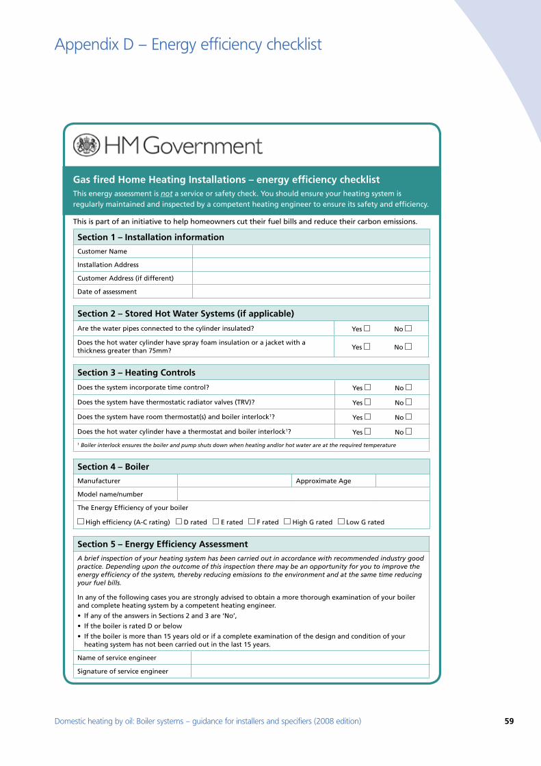
Domestic heating by oil: Boiler systems – guidance for installers and specifiers (2008 edition) 59
Appendix D – Energy efficiency checklist
Gas fired Home Heating Installations – energy efficiency checklistThis energy assessment is not a service or safety check. You should ensure your heating system is regularly maintained and inspected by a competent heating engineer to ensure its safety and efficiency.
This is part of an initiative to help homeowners cut their fuel bills and reduce their carbon emissions.
Section 1 – Installation information
Customer Name
Installation Address
Customer Address (if different)
Date of assessment
Section 2 – Stored Hot Water Systems (if applicable)
Are the water pipes connected to the cylinder insulated? Yes No
Does the hot water cylinder have spray foam insulation or a jacket with a thickness greater than 75mm? Yes No
Section 3 – Heating Controls
Does the system incorporate time control? Yes No
Does the system have thermostatic radiator valves (TRV)? Yes No
Does the system have room thermostat(s) and boiler interlock1? Yes No
Does the hot water cylinder have a thermostat and boiler interlock1? Yes No
1 Boiler interlock ensures the boiler and pump shuts down when heating and/or hot water are at the required temperature
Section 4 – Boiler
Manufacturer Approximate Age
Model name/number
The Energy Efficiency of your boiler
High efficiency (A-C rating) D rated E rated F rated High G rated Low G rated
Section 5 – Energy Efficiency Assessment
A brief inspection of your heating system has been carried out in accordance with recommended industry good practice. Depending upon the outcome of this inspection there may be an opportunity for you to improve the energy efficiency of the system, thereby reducing emissions to the environment and at the same time reducing your fuel bills.
In any of the following cases you are strongly advised to obtain a more thorough examination of your boiler and complete heating system by a competent heating engineer.
heating system has not been carried out in the last 15 years.
Name of service engineer
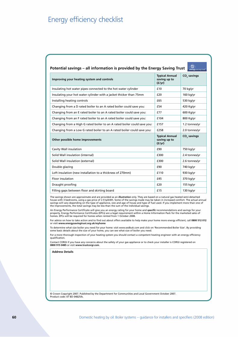
60 Domestic heating by oil: Boiler systems – guidance for installers and specifiers (2008 edition)
Energy efficiency checklist
Potential savings – all information is provided by the Energy Saving Trust
Improving your heating system and controlsTypical Annual saving up to (£/yr)
CO2 savings
Insulating hot water pipes connected to the hot water cylinder £10 70 kg/yr
Insulating your hot water cylinder with a jacket thicker than 75mm 160 kg/yr
Installing heating controls £65
Changing from a D rated boiler to an A rated boiler could save you: £54
Changing from an E rated boiler to an A rated boiler could save you: £77
Changing from an F rated boiler to an A rated boiler could save you: £104
Changing from a High G rated boiler to an A rated boiler could save you: £157
Changing from a Low G rated boiler to an A rated boiler could save you:
Other possible home improvementsTypical Annual saving up to (£/yr)
CO2 savings
Cavity Wall insulation £90 750 kg/yr
Double glazing £90 740 kg/yr
£110
Floor insulation £45
Draught proofing 155 kg/yr
Filling gaps between floor and skirting board £15
The savings shown are approximate and are provided as an illustration only. They are based on a natural gas heated semi-detached
An Energy Performance Certificate will give you an energy rating for your home and specific recommendations and savings for your property. Energy Performance Certificates (EPCs) are a legal requirement within a Home Information Pack for the marketed sales of
0800 512 012 or visit www.energysavingtrust.org.uk/myhome
For a more thorough inspection of your heating system you should contact a competent heating engineer with an energy efficiency qualification.
Contact CORGI if you have any concerns about the safety of your gas appliance or to check your installer is CORGI registered on 0800 915 0485 or visit www.trustcorgi.com.
Address Details
Domestic heating by oil: Boiler systems – guidance for installers and specifiers (2008 edition) 61
Simple explanations of the purpose and principles of domestic heating controls are necessary to help householders understand them, and encourage more effective usage. The following pages have been written in conjunction with control manufacturers to accompany the installation and commissioning instructions for individual products, and are included with heating controls that carry the Energy Saving Recommended logo.
1. What is a room thermostat?A room thermostat simply switches the heating system on and off as necessary. It works by sensing the air temperature, switching on the heating when the air temperature falls below the thermostat setting, and switching it off once this set temperature has been reached.
Turning a room thermostat to a higher setting will not make the room heat up any faster. How quickly the room heats up depends on the design of the heating system, for example, the size of boiler and radiators.
Neither does the setting affect how quickly the room cools down. Turning a room thermostat to a lower setting will result in the room being controlled at a lower temperature, and saves energy.
The heating system will not work if a time switch or programmer has switched it off.
The way to set and use your room thermostat is to find the lowest temperature setting that you are comfortable with, and then leave it alone to do its job. The best way to do this is to set the room thermostat to a low temperature – say 18°C – and then turn it up by one degree each day until you are comfortable with the temperature. You won’t have to adjust the thermostat further. Any adjustment above this setting will waste energy and cost you more money.
If your heating system is a boiler with radiators, there will usually be only one room thermostat to control the whole house. But you can have different temperatures in individual rooms by installing thermostatic radiator valves (TRVs) on individual radiators. If you don’t have TRVs, you should choose a temperature that is reasonable for the whole house. If you do have TRVs, you can choose a slightly higher setting to make sure that even the coldest room is comfortable, then prevent any overheating in other rooms by adjusting the TRVs.
Appendix E – Heating controls: simple explanations for householders
Room thermostats need a free flow of air to sense the temperature, so they must not be covered by curtains or blocked by furniture. Nearby electric fires, televisions, wall or table lamps may prevent the thermostat from working properly.
2. What is a cylinder thermostat?A cylinder thermostat switches on and off the heat supply from the boiler to the hot-water cylinder. It works by sensing the temperature of the water inside the cylinder, switching on the water heating when the temperature falls below the thermostat setting, and switching it off once this set temperature has been reached.
Turning a cylinder thermostat to a higher setting will not make the water heat up any faster. How quickly the water heats up depends on the design of the heating system, for example, the size of boiler and the heat exchanger inside the cylinder.
The water heating will not work if a time switch or programmer has switched it off. And the cylinder thermostat will not always switch the boiler off, because the boiler sometimes needs to heat the radiators.
Cylinder thermostats are usually fitted between one quarter and one third of the way up the cylinder. The cylinder thermostat will have a temperature scale marked on it, and it should be set at between 60°C and 65°C, then left to do its job. This temperature is high enough to kill off harmful bacteria in the water, but raising the temperature of the stored hot water any higher will result in wasted energy and increase the risk of scalding.
If you have a boiler control thermostat, it should always be set to a higher temperature than that of the cylinder thermostat. In most boilers, a single boiler thermostat controls the temperature of water sent to both the cylinder and radiators, although in some there are two separate boiler thermostats.
3. What is a programmer?Programmers allow you to set ‘On’ and ‘Off’ time periods. Some models switch the central heating and domestic hot water on and off at the same time, while others allow the domestic hot water and heating to come on and go off at different times.
62 Domestic heating by oil: Boiler systems – guidance for installers and specifiers (2008 edition)
Heating controls: simple explanations for householders
Set the ‘On’ and ‘Off’ time periods to suit your own lifestyle. On some programmers you must also set whether you want the heating and hot water to run continuously, run under the chosen ‘On’ and ‘Off’ heating periods, or be permanently off.
The time on the programmer must be correct. Some types have to be adjusted in spring and autumn at the changes between Greenwich Mean Time (GMT) and British Summer Time (BST).
You may be able to temporarily adjust the heating programme, for example, ‘Override’, ‘Advance’ or ‘Boost’. These are explained in the manufacturer’s instructions.
The heating will not work if the room thermostat has switched the heating off. And, if you have a hot-water cylinder, the water heating will not work if the cylinder thermostat detects that the hot water has reached the correct temperature.
4. What is a programmable room thermostat?A programmable room thermostat is both a programmer and a room thermostat. A programmer allows you to set ‘On’ and ‘Off’ time periods to suit your own lifestyle. A room thermostat works by sensing the air temperature, switching on the heating when the air temperature falls below the thermostat setting, and switching it off once this set temperature has been reached.
So, a programmable room thermostat lets you choose what times you want the heating to be on, and what temperature it should reach while it is on. It will allow you to select different temperatures in your home at different times of the day (and days of the week) to meet your particular needs.
Turning a programmable room thermostat to a higher setting will not make the room heat up any faster. How quickly the room heats up depends on the design of the heating system, for example, the size of boiler and radiators. Neither does the setting affect how quickly the room cools down. Turning a programmable room thermostat to a lower setting will result in the room being controlled at a lower temperature, and saves energy.
The way to set and use your programmable room thermostat is to find the lowest temperature settings that you are comfortable with at the different times you have chosen, and then leave it alone to do its job. The best way to do this is to set low temperatures first, say 18°C, and then turn them up by one degree each day until you are comfortable with the temperatures. You won’t have to adjust the thermostat further. Any adjustments above these settings will waste energy and cost you more money.
If your heating system is a boiler with radiators, there will usually be only one programmable room thermostat to control the whole house. But you can have different temperatures in individual rooms by installing thermostatic radiator valves (TRVs) on individual radiators. If you don’t have TRVs, you should choose a temperature that is reasonable for the whole house. If you do have TRVs, you can choose a slightly higher setting to make sure that even the coldest room is comfortable, then prevent any overheating in other rooms by adjusting the TRVs.
The time on the programmer must be correct. Some types have to be adjusted in spring and autumn at the changes between GMT and BST.
You may be able to temporarily adjust the heating programme, for example, ‘Override’, ‘Advance’ or ‘Boost’. These are explained in the manufacturer’s instructions.
Programmable room thermostats need a free flow of air to sense the temperature, so they must not be covered by curtains or blocked by furniture. Nearby electric fires, televisions, wall or table lamps may prevent the thermostat from working properly.
5. What is a timeswitch?A timeswitch is an electrical switch operated by a clock. It allows you to set ‘On’ and ‘Off’ time periods for either central heating or hot water. It can be arranged to control both central heating and hot water together, but will turn them both on and off at the same times. If you want to control both central heating and hot water and turn them on and off at different times, you should have a programmer instead of a timeswitch.
Domestic heating by oil: Boiler systems – guidance for installers and specifiers (2008 edition) 63
Heating controls: simple explanations for householders
Set the ‘On’ and ‘Off’ time periods to suit your own lifestyle. On some timeswitches you can choose whether you want the system to run continuously, run under the chosen ‘On’ and ‘Off’ periods, or be permanently off. You may also be able to adjust the on and off timing temporarily, e.g. ‘Override’ or ‘Advance’. These are explained in the manufacturer’s instructions.
The clock in the timeswitch must be set to the correct time. Some types have to be adjusted in spring and autumn at the changes between GMT and BST.
The heating system may have other controls that switch it on or off, e.g. the room thermostat will switch off the heating when the room has warmed up. And, if you have a hot water cylinder, the cylinder thermostat will switch off the water heating when it detects that the hot water has reached the correct temperature.
6. What is a thermostatic radiator valve (TRV)?TRVs sense the air temperature around them and regulate the flow of water through the radiator which they are fitted to. They do not control the boiler.
They should be set at a level that gives you the room temperature you want. These settings may have to be different in each room, and you should set the TRVs to suit each room and then leave them to do their job.
Turning a TRV to a higher setting will not make the room heat up any faster. How quickly the room heats up depends on the boiler size and setting, and the radiator size. Turning a TRV to a lower setting will result in the room being controlled at a lower temperature, and saves energy.
TRVs need a free flow of air to sense the temperature, so they must not be covered by curtains or blocked by furniture.
TRVs cannot turn off the boiler when the whole house is warm. To do that, you will need a room thermostat as well. The radiator in the room with the room thermostat should not normally have a TRV, but, if it does, keep the TRV on the maximum setting and adjust the room thermostat as explained with the instructions.
64 Domestic heating by oil: Boiler systems – guidance for installers and specifiers (2008 edition)
References used in CHeSS (year 2008) [1] The Building Regulations 2000. Approved
Documents L1A (New Dwellings) and L1B (Existing Dwellings), Conservation of fuel and power in dwellings, 2006 Edition.
[2] Section 6: Energy, Domestic Technical Handbook, Guidance on achieving the standards set in the Building (Scotland) Regulations 2004, Scottish Building Standards Agency, 2007. See website www.sbsa.gov.uk
[3] Domestic heating by gas: boiler systems:guidance for installers and specifiers: Energy Efficiency Best Practice in Housing (CE30).
[4] Domestic heating by oil: boiler systems:guidance for installers and specifiers: Energy Efficiency Best Practice in Housing (CE29).
[5] Domestic Heating Design Guide, CIBSE, 2007[6] The Government’s Standard Assessment
Procedure for Energy Rating of Dwellings, 2005 Edition.
[7] BS 1566:2002, Copper indirect cylinders for domestic purposes.
[8] BS EN 12897:2006, Specification for indirectly heated unvented hot water storage water heaters.
[9] Waterheater Manufacturers’ Association Performance Specification for Thermal Stores, 1999. [Shortly to be superseded by a revised 2008 specification from the HWA (Hot Water Association)].
[10] Benchmark Code of Practice for the Installation, Commissioning and Servicing of Central Heating Systems (available from Heating & Hot water Information Council, website www.centralheating.co.uk or telephone 0845 600 2200).
[11] The Building (Amendment No. 2) Regulations (Northern Ireland) 2006, Technical booklet F1, Conservation of fuel and power (2006). See website www.dfpni.gov.uk
[12] BS EN 12828:2003 Heating Systems in Buildings. Design for water based systems.
[13] BS 7671:2001, Requirements for electrical installations, IEE Wiring Regulations, Sixteenth edition.
[14] BS 7593:2006, Code of Practice for Treatment of water in domestic hot water central heating systems.
[15] European Standard (Telecommunications series) ETSI EN 300 220-1 v1.3.1 (2000-09):Electromagnetic compatibility and Radio spectrum Matters (ERM); Short Range Devices (SRD); Radio equipment to be used in the 25MHz to 1000MHz frequency range with power levels ranging up to 500 mW; Part 1:Technical characteristics and test methods.
[16] Domestic Heating Compliance Guide, (Compliance with Approved Documents L1A: New Dwellings and L1B: Existing Dwellings), First Edition, Communities and Local Government.
References used elsewhere in this guide [17] The Boiler (Efficiency) Regulations 1993, SI (1993)
No 3083, as amended by the Boiler (Efficiency) (Amendment) Regulations 1994, SI (1994) No 3083.
[18] The Building Regulations 2000. Approved Documents L1A (New Dwellings) and L1B (Existing Dwellings), Conservation of fuel and power in dwellings, 2006 Edition.
[19] Section 6: Energy, Domestic Technical Handbook, Guidance on achieving the standards set in the Building (Scotland) Regulations 2004, Scottish Building Standards Agency, 2007. See website www.sbsa.gov.uk
[20] The Building (Amendment No. 2) Regulations (Northern Ireland) 2006, Technical booklet F1, Conservation of fuel and power (2006). See website www.dfpni.gov.uk
[21] Domestic Heating Compliance Guide, (Compliance with Approved Documents L1A: New Dwellings and L1B: Existing Dwellings), First Edition, Communities and Local Government.
[22] The Government’s Standard Assessment Procedure for Energy Rating of Dwellings, SAP2005.
[23] Guide to the Condensing Boiler Installation Assessment Procedure for dwellings, CLG, DEFRA April 2005.
[24] Guide to the Condensing Boiler Installation Assessment Procedure for dwellings, SBSA.
[25] BS 1566:2002, Copper indirect cylinders for domestic purposes.
[26] BS 7671: 2008, Requirements for electrical installations, IEE Wiring Regulations, Seventeenth edition (from 1st July 2008).
[27] BS 3198:1981, Specification for copper hot water storage combination units for domestic purposes.
References
Domestic heating by oil: Boiler systems – guidance for installers and specifiers (2008 edition) 65
References
[28] BS EN 12897:2006, Specification for indirectly heated unvented hot water storage water heaters.
[29] Waterheater Manufacturers’ Association Performance Specification for Thermal Stores, 1999. [Shortly to be superseded by a revised 2008 specification from the HWA (Hot Water Association)].
[30] The Building (Amendment No 2) Regulations (Northern Ireland) 2000. Technical booklet F1, Conservation of fuel and power (2006). See website www.dfpni.gov.uk/
[31] Domestic heating by gas: boiler systems: guidance for installers and specifiers: Energy Efficiency Best Practice in Housing (CE30).
[32] Domestic Heating Design Guide, CIBSE, May 2007.
[33] Solar hot water installation guide: Energy Efficiency Best Practice Programme in Housing CE131 [2005].
[34] BS 5410-1:21997, Code of Practice for oil firing – Part 1. Installations up to 45kW output capacity for space heating and hot water supply purposes.
[35] BS EN 12831:2003 Heating Systems in Buildings. Method for calculation of design heat load.
[36] Under floor Heating, Design and Installation Guide), CIBSE, 2004.
[37] Taking Control, A Guide to buying or upgrading central heating controls, Ricability. See www.ricability.org.uk
[38] Central Heating System Specifications (CHeSS) – Year 2008 (CE51).
[39] Council Directive 92/42/EEC on efficiency requirements for new hot water boilers fired with liquid or gaseous fuels. Official Journal of the European Communities No L/167/17. 21 May 1992, p. 92.
[40] Domestic Energy Fact File 2006, J.I Utley and L D Shorrock, BRE.
[41] BREDEM-12, Building Research Establishment Report BR315. BRE, Garston, 1996.
[42] Boiler Efficiency Database. See website www.boilers.org.uk
[43] BS EN 12828:2003 Heating Systems in Buildings. Design for water based systems.
[44] Technical Information Book 4, OFTEC.[45] DCLG website www.planningportal.gov.uk; see
‘Building Regulations’ then ‘Technical guidance’ then ‘Approved documents’.
[46] Technical Information Book 3, OFTEC.[47] BS6798:2000 Specification for installation of
gas-fired boilers rated not exceeding 70kW net.[48] Solar Heating, Design and Installation Guide),
CIBSE, 2007.[49] The Building Regulations 2000. Approved
Document J, Combustion Appliances & Fuel Storage Systems.
[50] Section 3: Environment, Domestic Technical Handbook, Guidance on achieving the standards set in the Building (Scotland) Regulations 2004, Scottish Building Standards Agency, 2007. See website www.sbsa.gov.uk
[51] SR2006 No.335 The Building (Amendment) Regulations (Northern Ireland) 2006.
[52] Statutory Instrument 2001 No. 2954. The control of Pollution (Oil Storage) (England) Regulations 2001.
[53] Scottish Statutory Instrument 2006 No. 133 The Water Environment Oil Storage (Scotland) Regulations 2006.
[54] SR2003 No.319 The Control of Pollution (Sileage, Slurry and Agricultural Fuel Oil Regulations (Northern Ireland).
[55] Installing Oil Supply Pipes Underground, OFTEC Ref TI/134.
[56] BS EN 14336:2004 Heating Systems in buildings. Installation and commissioning of water based systems.
[57] BS 7593:2006, Code of Practice for Treatment of water in domestic hot water central heating systems.
[58] Form CD/10 Installation Completion report. OFTEC.
[59] Form CD/11 Servicing and Commissioning Report. OFTEC.

CE29
This publication (including any drawings forming part of it) is intended for general guidance only and not as a substitute for the application of professional expertise. Anyone using this publication (including any drawings forming part of it) must make their own
assessment of the suitability of its content (whether for their own purposes or those of any client or customer), and the Energy Saving Trust cannot accept responsibility for any loss, damage or other liability resulting from such use.
All technical information was produced by BRE on behalf of the Energy Saving Trust.
CE29 © Energy Saving Trust February 2005. Revised June 2008. E&OE
Energy Saving Trust 21 Dartmouth Street London SW1H 9BP Tel 0845 120 7799 Fax 0845 120 7789
[email protected] www.energysavingtrust.org.uk/housing