domestic repair station and uality control … · domestic repair station and quality control...
TRANSCRIPT

DOMESTIC REPAIR STATION AND
QUALITY CONTROL MANUAL’S FOR
West Star Aviation, Inc. (GJT)
796 Heritage Way Grand Junction Regional Airport
Grand Junction, Co 81506 Federal Aviation Administration Repair Station
Certificate Number WTXR173J &
West Star Aviation, Inc. (ASE) Additional Fixed Location
Aspen-Pitkin County Airport/Sardy Field 12 West Airport Road
Aspen, CO 81611
Kevin T. Bostwick Accountability Manager/Quality Assurance Manager
REVISION LEVEL
Manual Copy Number
10
Date: JAN/15/2015
REPAIR STATION MANUAL 14CFR §145.209
NOTE: ANY AND ALL FORMS, STAMPS OR TAGS REFERENCED IN THIS MANUAL CAN BE
FOUND BY USING THE INDEX LOCATED IN APPENDIX B. WEST STAR NUMBERS THEIR
FORMS USING THE PREFIX OF, “WSF” FOR INTERNAL CONTROL

REPAIR STATION MANUAL
Preface: Doc. No.: Effective Date: Revision No.: Page:
i
01/15/15 Rev. 10
1 of 2
i (TOC) Rev. 10.doc
TABLE OF CONTENTS
REPAIR STATION MANUAL POLICIES AND PROCEDURES
NOTE: If viewing this manual in a digital format, click on the individual line items below which are hyperlink to the document
TABLE OF CONTENTS ............................................................................................. i LIST OF EFFECTIVE PAGES ................................................................................... ii RECORD OF REVISIONS ........................................................................................ iii MANUAL REVISION INSTRUCTION AND CONTROL FORM ................................ iv
Chapter 1: GENERAL AND ADMINISTRATIVE PROCEDURES
Title Page ........................................................................................................ 1.000 Introduction ................................................................................................. 1.010 Manual Distribution, Control and Revision Processes ................................ 1.020 Work Performed at a Location Other Than Fixed Location ......................... 1.030 Additional Fixed Location ............................................................................ 1.035 Work Performed After Regular Business Hours .......................................... 1.040
Chapter 2: ORGANIZATION
Title Page ........................................................................................................ 2.000
Organizational Chart ................................................................................... 2.010 Management Responsibility ........................................................................ 2.020 General Manager ........................................................................................ 2.030 Removed .................................................................................................... 2.040 Accountability Manager .............................................................................. 2.050 Quality Assurance Manager ........................................................................ 2.060 Quality Assurance Team Leader ................................................................ 2.070 Quality Assurance Inspector ....................................................................... 2.080 Category I Quality Control Inspector ........................................................... 2.090 Category II Quality Control Inspector .......................................................... 2.100 Aircraft Services Manager ........................................................................... 2.110 Page Not Used ........................................................................................... 2.120 Paint Program Manager .............................................................................. 2.130 Interior Program Manager ........................................................................... 2.140 Accessories Program Manager ................................................................... 2.150 Avionics Program Manager ......................................................................... 2.160 Avionics Install Team Leader ...................................................................... 2.170 Avionics Repair Assistant Manager ............................................................ 2.180 Director of Maintenance .............................................................................. 2.190 Program Manager ....................................................................................... 2.200 Team Leader .............................................................................................. 2.210 Technician .................................................................................................. 2.220 Apprentice Mechanic .................................................................................. 2.230

REPAIR STATION MANUAL
Preface: Doc. No.: Effective Date: Revision No.: Page:
i
01/15/15 Rev. 10
2 of 2
i (TOC) Rev. 10.doc
Engineer Manager ...................................................................................... 2.240 Engineer ..................................................................................................... 2.250 Engineer Designer ...................................................................................... 2.260 NDT Team Leader ...................................................................................... 2.270 Materials Control Manager .......................................................................... 2.280 Purchaser ................................................................................................... 2.290 Parts Manager ............................................................................................ 2.300 QA Training Coordinator ............................................................................. 2.310 NOT USED ................................................................................................. 2.320
Chapter 3: REPAIR STATION OPERATION REQUIREMENTS Title Page ........................................................................................................ 3.000 Personal Requirements .............................................................................. 3.010
Supervisory Requirements.......................................................................... 3.020 Rosters ....................................................................................................... 3.030 Equipment, Materials & Tooling Requirements ........................................... 3.040
Chapter 4: HOUSING & FACILITIES Title Page ........................................................................................................ 4.000
Housing & Facility Requirements ................................................................ 4.010 Housing & Facility Change of Location ....................................................... 4.020
Chapter 5: TRAINING Title Page ........................................................................................................ 5.000
Training System .......................................................................................... 5.010 REMOVED .................................................................................................. 5.020
Chapter 6: CONTRACT MAINTENANCE PROVIDER Title Page ........................................................................................................ 6.000
Contract Maintenance Requirements .......................................................... 6.010 Contract Vendor Qualification Requirements .............................................. 6.020
Chapter 7: Self-Evaluation Program Title Page ........................................................................................................ 7.000
Self Evaluation Program ............................................................................. 7.010
APPENDIXES Appendix A: Contract Maintenance Function List Appendix B: Repair Station Forms Index Appendix C: Electronic Signatures
EASA SUPPLEMENT
CANADIAN SUPPLEMENT

Repair Station Manual
Preface Doc. No.: Effective Date: Revision No.: Page:
ii
01/15/15 Rev. 10
1 of 1
LIST OF EFFECTIVE PAGES
ii (LOEP), Rev. 10.doc
DOC NO PAGES REV.
LEVEL DATE
i 1 10 JAN/15/2015 2 10 JAN/15/2015 ii 1 10 JAN/15/2015 iii 1 10 JAN/15/2015 iv 1 7 JAN/01/2012
1.000 1 3 JUL/07/2007 1.010 1 6 JUN/01/2010 1.020 1 10 JAN/15/2015
2 10 JAN/15/2015 1.030 1 10 JAN/15/2015
2 10 JAN/15/2015 3 10 JAN/15/2015
1.035 1 4 JUL/01/2008 2 4 JUL/01/2008
1.040 1 5 OCT/01/2009 2.000 1 3 JUL/01/2007 2.010 1 10 JAN/15/2015 2.020 1 3 JAN/01/2012 2.030 1 8 AUG/15/2012 2.040 1 7 NOT USED 2.050 1 7 JAN/01/2012 2.060 1 7 JAN/01/2012
2 7 JAN/01/2012 2.070 1 3 JULY/01/2007 2.080 1 3 JULY/01/2007 2.090 1 7 JAN/01/2012 2.100 1 4 JULY/01/2008 2.110 1 4 JULY/01/2008 2.120 1 4 REMOVED 2.130 1 4 JUL/01/2008
2 4 JUL/01/2008 2.140 1 4 JUL/01/2008
2 4 JUL/01/2008 2.150 1 4 JUL/01/2008 2.160 1 4 JUL/01/2008
2 4 JUL/01/2008 2.170 1 4 JUL/01/2008 2.180 1 4 JUL/01/2008 2.190 1 8 AUG/15/2012 2.200 1 5 OCT/01/2009 2.210 1 4 JUL/01/2008 2.220 1 3 JUL/01/2007 2.230 1 5 OCT/01/2009
DOC NO PAGES REV.
LEVEL DATE
2.240 1 3 JUL/01/2007 2.250 1 3 JUL/01/2007 2.260 1 3 JUL/01/2007 2.270 1 4 JUL/01/2008
2 4 JUL/01/2008 2.280 1 4 JUL/01/2008 2.290 1 3 JUL/01/2007 2.300 1 5 OCT/01/2009 2.310 1 3 JUL/01/2007 2.320 1 7 NOT USED 3.000 1 3 JUL/01/2007 3.010 1 7 JAN/01/2012
2 7 JAN/01/2012 3.020 1 3 JUL/01/2007 3.030 1 7 JAN/01/2012 3.040 1 5 OCT/01/2009
2 5 OCT/01/2009 4.000 1 3 JUL/01/2007 4.010 1 7 JAN/01/2012 4.020 1 7 JAN/01/2012 5.000 1 3 JUL/01/2007 5.010 1 7 JAN/01/2012 5.020 1 9 MAR/01/2014 6.000 1 9 MAR/01/2014 6.010 1 9 MAR/01/2014
2 9 MAR/01/2014 3 9 MAR/01/2014
6.020 1 9 MAR/01/2014 2 9 MAR/01/2014
7.000 1 7 JAN/01/2012 7.010 1 7 JAN/01/2012
2 7 JAN/01/2012 Appendix A 1 9 MAR/01/2014 Appendix B 1 10 JAN/15/2015 Appendix C 1 7 JAN/01/2012
2 7 JAN/01/2012 EASA
SUPPLEMENT 7 MAR/07/2014
CANADIAN SUPPLEMENT 1 JUL/01/2007
Approval: Acceptance of:
West Star Aviation: ________________________ FAA FSDO: __________________________ Accountable Manager Principal Maintenance Inspector

Repair Station Manual/Quality Control Manual
Preface Doc. No.: Effective Date: Revision No.: Page:
iii
01/15/15 Rev. 10
1 of 1
iii (ROR), Rev. 9.doc
RECORD OF REVISIONS
Manual No. _____________
NOTE: Electronic versions of this manual may have the manual number and revision date
displayed on the disc or CD in lieu of the spaces provided on this page. Since electronic versions of this manual are completely reissued at each revision, the last “date inserted” and “initials” may remain blank on electronic copies of this document.
Retain this record in the manual. Upon receipt of revisions, insert revised pages in the manual and enter the revision number, revision date, insertion date, and initials of person incorporating the revision in the appropriate block on this page. Complete and return the Revision Control Form to the Quality Assurance Manager or designee. All personnel are expected to suggest revisions to the Accountability Manager or their supervisor.
Revision Number Revision Date Date Inserted Initials
Original January 31, 2004 January 31, 2004 KTB
Rev. 1 September 8, 2004 September 8, 2004 KTB
Rev. 2 February 28, 2006 February 28, 2006 KTB
Rev. 3 July 1, 2007 July 1, 2007 KTB
Rev. 4 July 1, 2008 July 1, 2008 KTB
Rev. 5 October 1, 2009 October 1, 2009 KTB
Rev. 6 June 1, 2010 June 1, 2010 Signature on File in the
QA Office
Rev. 7 January 01, 2012 January 01, 2012 Signature on File in the
QA Office
Rev. 8 August 15, 2012 August 15, 2012 Signature on File in the
QA Office
Rev. 9 March 01, 2014 March 01, 2014 Signature on File in the
QA Office
Rev. 10 January 15, 2015 January 15, 2015 Signature on File in the
QA Office

Repair Station Manual/Quality Control Manual
Preface Doc. No.: Effective Date: Revision No.: Page:
iv
01/01/12 Rev. 7 1 of 1
iv (EXAMPLE).doc
WSF 027
REPAIR STATION & QUALITY CONTROL MANUAL REVISION INSTRUCTION AND CONTROL FORM
MANUAL TITLE BEING REVISED: WEST STAR REPAIR STATION & QUALITY CONTROL MANUAL NUMBER BEING REVISED: _______________________ REVISION NUMBER BEING INSERTED: __________________ MANUAL REVISION INSTRUCTIONS: Carefully review each page of this revision, until you understand the scope, nature and effect of the changes to the manual being revised. Compare each revised page for details of specific changes. Your questions regarding this revision may be addressed to the Quality Assurance Manager. When you understand each change, revise paper copies of the manual per the following instructions. NOTE: Since electronic versions are reissued in their entirety, no revision action is necessary. Instructions 1 and 2
below may be ignored for electronic versions. 1) Insert a page of the new revision into the manual. If there is already a page in the manual, with the identical page
number, remove the old page. If the page of the new revision does not have an identical, corresponding page already in the manual, place the new page in the correct numerical order. When the revision is complete, the manual should have no duplicated page numbers, with different revision dates or numbers. The pages that were revised and removed may be destroyed.
2) When all pages of the revision are inserted, and all applicable pages of the previous revision are removed,
complete the Record of Revisions page of the manual. Some manuals may not have a Record of Revisions page. Typically, a Record of Revisions page will include the following information:
- Revision Number - Revision Date - Date Inserted - Initials 3) SPECIAL INSTRUCTIONS FOR THIS REVISION: REVISION CONTROL INSTRUCTIONS: When the manual has been revised according to the above instructions, read the following statement and sign and date this form. Return this form to the Quality Assurance Manager for West Star at: West Star 796 Heritage Way Grand Junction, CO 81506 Attn: Quality Assurance Manager I have reviewed the above referenced revision and understand the contents of the revision. I have revised the manual according to the above listed instructions. If I have been issued an electronic version of a manual, I also certify that I have access to the computer and software necessary to view all pages of my copy of the manual. I also certify that I understand the use of the computer and software and I am able to view each page of my electronic copy of the manual without assistance. _______________________________________ ______________ NAME (Print) DATE _______________________________________ ______________ SIGNATURE INITIALS

Repair Station Manual
Chapter: Doc. No.: Effective Date: Revision No.: Page:
1 1.000
07/01/07 Rev. 3 1 of 1
1.000
CHAPTER 1
GENERAL AND ADMINISTRATIVE PROCEDURES

Repair Station Manual
Chapter: Doc. No.: Effective Date: Revision No.: Page:
1 1.010
06/01/10 Rev. 6 1 of 1
1.010
Title: REPAIR STATION MANUAL INTRODUCTION (14CFR §145.209) 1.0 Purpose: This repair station manual includes a description of the policies and procedures
that will be used by this repair station to meet all requirements of 14 CFR Part 145.
2.0 Responsibilities:
2.1 All Repair Station Key Personnel are required to be familiar with the requirements of this manual and the applicable FAA Regulations.
2.2 The Individual Hangar libraries will have a hard copy of the manual to include, department
head supervisors of which all technicians will have access to including the electronic version located and accessed on the company intranet. There will be additional copies maintained in the inspection office when a West Star technician is tasked to work away from base. This travel copy will be checked out by the technician. This Repair Station Manual will be combined with the Quality Control Manual in one binder. These manuals will be tracked as one. A list of manual assignments by individual or location will be maintained in the Inspection office.
2.3 Manual holders are responsible for maintaining their assigned manuals to current revision status, and for ensuring that all personnel under their supervision have access to and are familiar with the contents of the manual and adhere to its provisions, to include the electronic version located and accessed on the company intranet.
3.0 Procedures:
3.1 This manual will describe the housing, facilities, equipment, personnel, and general operating rules pertinent to the operation of this domestic repair station, certificated by the Federal Aviation Administration (FAA) under 14 CFR Part 145. All ratings issued to this repair station by the FAA under Part 145 are described in its Operations Specifications and in this manual.
NOTE: This Repair Station elects not to use the option of a capability list as described in 14CFR §145.209 (d) (1) (2) and 14CFR§145.215. All ratings will be listed in the Operation Specifications.
3.2 The information contained in this manual explains the systems used by the repair station
when performing routine/non-routine maintenance, preventive maintenance or alteration on civil aviation articles. When more detail is required to accomplish or record a particular operation, those details are contained in the applicable manufacturer’s instructions for continued airworthiness (e.g., maintenance, overhaul and repair manuals), service bulletins, service information letters, Airworthiness Directives, and/or other data acceptable to or approved by the FAA.
3.3 The maintenance, preventive maintenance, or alteration of civil aviation articles will be
performed in accordance with the applicable Federal Aviation Regulations (FARs). The repair station will not maintain or alter any article for which it does not hold an appropriate rating. The repair station will not maintain or alter any article for which it is rated if the appropriate housing, facilities, equipment, personnel, or technical data are not available or not acceptable to the administrator.

Repair Station Manual
Chapter: Doc. No.: Effective Date: Revision No.: Page:
1 1.020
01/15/15 Rev. 10
1 of 2
1.020, Rev. 10.doc
Title: MANUAL DISTRIBUTION, CONTROL AND REVISION PROCESSES (14CFR §145.209 (k) & §145.211 (c)(4))
Note: The following procedures apply to both the Repair Station and Quality Control Manual 1.0 Purpose:
1.1 To establish a means of manual distribution, control and to ensure revisions to the Repair Station & Quality Control Manual are distributed and inserted into all manuals in a timely manner.
2.0 Responsibilities:
2.1 It shall be the responsibility of the Quality Assurance Manager for coordinating all revisions to this manual with the local Flight Standards District Office.
2.2 It shall be the responsibility of all personnel to ensure all revisions are read, inserted
and recorded in a timely manner for the Repair Station and Quality Control Manual, electronic or hard copy where applicable.
3.0 Procedures:
3.1 Each manual will have a control number and an assignment entry on the manual cover page. A master list containing the manual number, location and revision status will be kept in the Inspection Office. With the assistance of West Star’s computer department, an electronic version of the manual will be maintained and revised on the company Intranet of which all technicians have access, (Reference Appendix C of this manual for additional information on the electronic format of the Repair Station & Quality Control manuals). Production will be notified through their managers via email a new revision has been posted on the company intranet. At that time, it will be the responsibility of production to access the revised Repair Station/Quality Control Manual via the company intranet or hard copy and become familiar with the revisions.
3.2 The Repair Station Manual shall be revised as required consistent with current
operations. The Quality Assurance Manager will review this Repair Station Manual once each year confirming the manual is still current and valid for use, or identify needed changes. The Quality Assurance Manager will have any revisions he finds necessary produced in a final form and he will approve this by signing the list of effective pages for coordination with the FAA Flight Standards District Offices (“FAA FSDO”) at Salt Lake City, Utah as described below.
3.3 To maintain a clean, professional appearing manual, each procedure within a
Chapter will be given a separate document number. In the top right corner of each page, the Chapter Number, Document Number, Effective Date, Revision Number and number of pages for that document will be listed.
3.4 Formal revisions will be published as a complete new document rather than revising
individual pages. (Example): If a revision is required within document # 1.020, the entire document titled under 1.020 will be replaced with the revision. A bold vertical line in the left or right margin will indicate the revised part of the document.

Repair Station Manual
Chapter: Doc. No.: Effective Date: Revision No.: Page:
1 1.020
01/15/15 Rev. 10
2 of 2
1.020, Rev. 10.doc
3.5 The revised document will carry a new Effective Date and Revision Number. The
List of Effective Pages will be revised to show the latest issue dates. 3.6 The FAA Accountable Manager will send one paper copy with an additional copy
of the signature page, (List of Effective Pages) of each revision to the Flight Standards District Office for review. The revision package must include all revised pages including a revised list of effective pages. Upon acceptance of the proposed revision, the FAA Flight Standards District Office will sign and date the revision acceptance statement on the List of Effective Pages. One signed copy of the signature page, (List of Effective Pages) is then returned and the other retained to revise the Flight Standards District Office's copy of the manual. Receipt of the returned paper copy, of the signature page, from the FAA FSDO by the repair station signifies revision of the Flight Standards District Office's copy of the manual.
3.7. Upon receipt of the FAA accepted paper revision, the Quality Assurance
Manager will distribute paper copies of the revised pages to those persons assigned a paper copy of the manual, and attach a copy of West Star Aviation form WSF.027, to each copy. A sample of WSF.027 is included in the preface. Upon receipt of the paper revision, each paper manual holder is responsible for reviewing, understanding and inserting the revised pages into his/her assigned manual and recording the revision on the manual’s Record of Revision page.
Note: West Star is authorized to implement, revise and use the Repair Station and Quality Control Manual prior to FAA acceptance.
3.8 The Quality Assurance Manager shall also create a complete new PDF copy of
the revised electronic version of the manual. This electronic version will be located on the company Intranet and can be accessed by clicking on the “Quality” tab on the LH side of the screen. The newly revised electronic version shall contain all revised pages, correctly inserted. All personal using an electronic version of the manual is responsible for reviewing and understanding the changes to the manual.
3.9 Once paper copies of the manual have been revised, reviewed and understood,
and electronic versions have been received, reviewed and understood, each manual holder shall sign and date a copy of Form WSF.027 and return it to the Quality Assurance Manager. Form WSF.027 is used to certify that the revision has been reviewed and is understood by the manual holder and that all revised pages have been inserted into paper copies of the manual. Returned copies of Form WSF.027 are kept on file in the Inspection office and serve as a means of assuring Repair Station & Quality Control Manual Revision Status Control.
4.0 Acceptance and Approval signatures within the Repair Station, Quality Control, EASA
and Canadian manuals will be kept in hard copy in the Quality Assurance department.

Repair Station Manual
Chapter: Doc. No.: Effective Date: Revision No.: Page:
1 1.030
01/15/15 Rev. 10
1 of 3
1.030, Rev. 10.doc
Title: WORK PERFORMED AWAY FROM FIXED LOCATION/AWAY FROM BASE (AWB) (14CFR §145.103 (c) & §145.203) 1.0 Purpose:
1.1 To establish guidelines by which work can be accomplished on a customer's aircraft at a place other than the Repair Station.
NOTE: Work away from fixed location includes: On a recurring basis, temporary/emergency basis-short term and extended.
2.0 Responsibilities:
2.1 West Star will provide maintenance service for its customers at a place away from the Repair Station. West Star Aviation may only provide service for which the Repair Station is rated. The following, may open an away from base work order by following these steps: -Billing Department -Program Manager -Team Leader -Technician 2.1.1 Those listed above will create work orders as required specifically for AWB. They will do this by pre-
loading the Preliminary squawk with the following statement in the discrepancy:
“The Quality Assurance Manager or Quality Assurance Inspector” has approved this work order for the purposes of: “Work performed at a place other than the Repair Station.” Travel Destination: (City, State and Airport ID)
2.1.2 The Quality Assurance Manager or Quality Assurance Inspector will approve the work order by opening the
Preliminary Squawk in Corridor and approving it for “Parts”, “Labor” and “Services”. This will signify the approval for the work away from station.
2.2 The Director of Maintenance, Program Manager or Team Leader will be responsible for assigning the personnel
necessary to perform the work and the Program Manager or Team Leader will be considered responsible for the AWB Technician(s) while at the location.
2.3 The Director of Maintenance, Program Manager or Team Leader will ensure that the transport of tools and equipment will be done so to prevent any damage while in route. To include that all tools requiring calibration will be in calibration before departing the fixed location.
2.4 The Director of Maintenance, Program Manager or Team Leader will be responsible to ensure the technician
assigned work away from station has the appropriate qualifications and authority to return an aircraft, engine, or component to service and has all required forms and the work is completed as necessary. At a minimum, at least one of the personnel chosen must have return to service authority. Reference West Star form WSF 009K, (Return to Service Authority) for technicians with that authority. The only exception to this requirement is if the technician is only being asked to support a work scope with no expectation of approval for return to service.
3.0 Procedures: 3.1 The Director of Maintenance Program Manager or Team Leader will ensure that the article to undergo maintenance
and the work force will be in an area safe for the work to be performed and that they will have adequate protection from the elements. The Director of Maintenance, Program Manager and Team Leader will be responsible to provide all the necessary manpower, work forms, technical data, tools, and equipment necessary for the accomplishment of the maintenance. The Director of Maintenance, Program Manager or Team Leader will establish a system of communications between the away from base technicians and the Repair Station via Phone, texting, email and or remote West Star network access. 3.1.1 If maintenance/inspection to be performed is due to an accident, a Hidden Damage Inspection including
the areas next to the obvious damaged parts must be complied with in accordance with the Quality Control Manual Chapter 3, (4.0).
3.2 When utilizing the Corridor work order system for approval for return to service, the technician will have with him a
hard copy of the work order squawks(s). As needed, the technician will complete the work and inspections on the hard copy using wet signatures or initials.

Repair Station Manual
Chapter: Doc. No.: Effective Date: Revision No.: Page:
1 1.030
01/15/15 Rev. 10
2 of 3
1.030, Rev. 10.doc
3.3 Upon completion of the work, the Technician will transcribe the work performed off the hard copy into the Corridor system and the QA department will “Complete” the squawk(s) digitally. Ref. QCM Doc. No. 3.005 para. 2.10 for disposition of WO hard copy. NOTE: If work is to be performed and full access to the Corridor system is available at the GJT facility via remote
access, then all requirements of QCM Doc. No. 3.005 will be followed as required.
3.4 Whenever possible, all Away from Base work scopes will be approved prior to the technician departing, to ensure all elements of an AWB event are in place. The Program Manager, Team Leader or Technician will complete WSF 1501. Once complete, a copy of this form will be forwarded to the Quality Assurance Manager or Quality Assurance Inspector. Once the QA Manager or Inspector is satisfied with the completion of WSF 1501, they will approve the AWB work scope via the process indicated in para. 2.1.2 of this document.
3.5 All work functions will be accomplished in accordance with West Star Repair Station & Quality Control Manual in
conjunction with the manufacture recommendations and the owner/operators/air carrier maintenance/inspection program.
3.6 The Materials Control Manager will be responsible for assigning a stock person who will provide parts and
supply support between the repair station and the field personnel. All articles disassembled by repair station personnel outside the repair station will be protected from the elements and properly segregated to eliminate contamination or damage. The inspector(s) assigned will inspect each component and tag accordingly. All tags normally used within the repair station may be used for work outside the repair station.
3.7 All personnel assigned to accomplish work away from the Repair Station shall accomplish the specific function of
work in the same manner as when performed at the Repair Station.
3.8 All (RII) Required Inspection items shall be inspected and stamped/signed off by personnel, who have been trained, qualified and authorized by the Operator/Air Carrier.
3.9 The following will be observed for work performed outside of the premises of the repair station.
3.9.3 It is permissible for the person performing the work to inspect his or her own work, when properly
authorized and on a case-by-case basis with prior approval by the Quality Assurance Manager with the exception of an Operator/Air Carrier with RII requirements. The Operator/Air Carrier Manual must be followed.
3.9.6 A Team Leader shall be designated to be in charge of the function to be performed. His responsibilities will include assuring compliance with all FAR requirements. The Team Leader need not be at the site of the maintenance if the person performing the maintenance is properly certificated.
3.9.7 If any assistance is provided by any individual or company with their tooling, the tooling must be verified that it has current calibration as required by West Star Quality Control Manual Chapter 4.
3.9.8 Technicians assigned work away from base duties, will at all times, have on their person, West Star form WSF 053A, (Repair Station Inspection Authority), card. This card will indicate approval from the QA Manager that the technician has return to service authority for the repair station.
3.9.9 Technicians assigned work away from base duties, will at all times, have available to them a current copy of the West Star RSM/QCM in a paper or digital format.
3.9.10 If work away from station is to be accomplished on any EASA registered aircraft, the work and return to service must be accomplished in accordance with the West Star EASA supplement attached to this Repair Station Manual.
3.9.11 If work away from station is to be accomplished on any foreign registered aircraft, the work and approval for return to service must accomplished in accordance with the foreign Civial Aviation Authority requirements.
3.10 The following is a list of items required for Work Away from Station:

Repair Station Manual
Chapter: Doc. No.: Effective Date: Revision No.: Page:
1 1.030
01/15/15 Rev. 10
3 of 3
1.030, Rev. 10.doc
REQUIREMENTS PRIOR TO DEPARTURE FROM THE REPAIR STATION
1.
WSF 1501, Away from Base Check List will be completed prior to commencement of work for an AWB event. Ref. QCM Doc. No. 5.120 for instructions for use of WSF 1501. Upon completion of this form and during normal business hours, it will be provided to the QA Manager or Inspector via hard copy or electronically as soon as possible, at which time the QA Manager or Inspector will approve the AWB event via para. 2.1.2 of this document. In the event, the AWB event occurs after normal business hours, the technician is still responsible for this forms completion and routing to the QA Manager or Inspector, as indicated.
2.
Billing department will have in suspense, "Work Away from Station" work orders as they do for "After Hours". Locate those work order numbers on the Intranet by clicking on the "Aircraft Scheduling" link. These work orders will be distinguishable by a statement in the Preliminary discrepancy that states,
"The Quality Assurance Manager or Quality Assurance Inspector has approved this work order for the purposes of, "Work performed at a place other than the Repair Station." Travel Destination: (City, State and Airport ID)
3. Ensure you have the appropriate tooling for the work scope. 4. Ensure you have the appropriate and current technical publications, (M/M, I.P.C., Repair Station Manual, etc.).
5. Ensure you have a person on your team which has the appropriate approval for return to service authority for the work to be performed as indicated on the Repair Station Authority card, WSF 053A. A & P or Repairman certificate is required for approval for return to service authority.
6. If you are tasked with approval for return to service, along with your Repair Station Authority Card, WSF053A, ensure you have your A & P or Repairman certificate at the work site.
7. Ensure you are qualified with the training and knowledge for the work to be performed. 8. Ensure the facilities to be worked are adequate for the work scope.
9.
Check with customer contact as to how the aircraft is operated. If the aircraft is operated under Part 135, coordinate your maintenance efforts with their owner/operators Director of Maintenance or Maintenance control. If you are conducting an inspection you will have to follow their guidance within their General Maintenance Manual, which they are supposed to provide.
10. Working with the owner operator, determine how the aircraft is going to be approved for return to service via the documented maintenance, i.e. customer logs, using West Star’s printed squawks.
11. Print the Preliminary and work scope squawk(s) to have with you in the event Corridor access is not possible.
REQUIREMENTS AT THE AIRCRAFT WHERE MAINTENANCE IS TO BE PERFORMED
1.
Fill out as required and place WSF 1500, MRT Maintenance Release form in a place on or in the aircraft capable of being seen by anyone who enters. Ref. QCM Doc. No. 5.119 for instructions use for WSF 1500. Obtain current airframe, engines, props or APU times and cycles as required for the work scope. Document this information within the Preliminary corrective action block within the work order. If not possible, handwrite this information on a printed version of the Preliminary Squawk.
2.
Upon completion of maintenance, you must provide the owner/operator with a maintenance log entry. This can be in the form of using the owner/operators maintenance logs or printed squawk from the Corridor system. Upon returning to the repair station, coordinate with the QA department to generate a more formal log entry log book sticky, to be mailed to the owner/operator.
3. The technician working away from station is responsible to ensure all parts installed have all the correct traceability (C of C, 8130-3’s) prior to installation.
4. Upon completion of approval for return to service, all original documents, maintenance log entries, parts traceability, owner/operator maintenance logs, etc. will be provided to the owner/operator. Make copies of all these documents to be returned to the QA department.
3.10.1 In the event the technician that has been tasked to perform away from base functions determines he/she must
deviate from the established procedures of West Star’s fixed location, the technician will contact the Quality Assurance Manager or Director of Maintenance immediately for a resolution prior to commencing work.

Repair Station Manual
Chapter: Doc. No.: Effective Date: Revision No.: Page:
1 1.040
10/01/09 Rev. 5 1 of 1
1.040
Title: WORK PERFORMED AFTER REGULAR BUSINESS HOURS 1.0 Purpose:
1.1 To provide guidelines for West Star technicians to perform maintenance functions after
regular business hours which includes before 6:00 a.m., after 5:00 p.m., weekends and holidays.
2.0 Responsibilities: 2.1 It will be the responsibility of the maintenance technician to follow the guidelines of this
section as it relates to performing maintenance after regular business hours. 3.0 Procedures:
3.1 Periodically, West Star will perform maintenance functions after regular business hours. West Star will only provide service after hours for work for which the repair station is rated.
3.2 The Director or Manager of the respective department is responsible for assigning the
personnel necessary to perform that work and appoint a Team Leader. The Quality Assurance Manager or QA Inspector will be responsible to ensure the technician assigned “after hours duties” has the appropriate knowledge and authority to return an aircraft, engine, accessory or component to service and assure that all required forms and work are completed as necessary.
3.2.1 Technicians assigned after hour duties, will at all times, have on their person,
West Star form WSF 053A, (Repair Station Inspection Authority), card. This card will indicate approval from the QA Manager the technician is authorized for after hour duties.
3.3 The billing department will have work orders opened in Corridor to be used specifically for
after hours. The work order will have, “ADMINISTRATION ACCOUNT” as the customer, the work order will be titled “AFTER HOURS” and initially be opened to the QUALITY CONTROL department. A Preliminary Inspection Item with squawk will be in place along with all department Item’s you would typically see on a work order including “Quality Assurance”. The “Quality Assurance” item will have a squawk preloaded for return to service”. It will be the responsibility of the technician to sign off the return to service squawk as long as he/she has return to service authority. Understand that anyone Item that does not have a squawk loaded under it will not show up on the Invoice. If a work order copy is requested, you will print the “Work Order Detail” report found on the LH side explorer pane. Upon use of these work orders, notify the QA department on the next business day to ensure appropriate return to service has been documented and notify the billing department to ensure the appropriate posting to the appropriate customer and department is completed for final invoicing. This will also trigger another work order to be opened for the next time. The billing department will have open and ready to use, after hours work orders. They will only be used for this purpose. This ensures that the process of opening work orders remains consistent. The billing department will notify, via email, the after hours work orders numbers to the appropriate team leaders as they are opened. It will be the responsibility of the Team Leaders to notify their technicians of these work order numbers should they be called out after hours or during the weekend.
3.4 It is permissible for the person performing work after hours to inspect his or her own work
when so authorized on a case-by-case basis by the Quality Assurance Manager with the exception of an Operator/Air Carrier with RII requirements. The Operator/Air Carrier Manuals must be followed.

Repair Station Manual
Chapter: Doc. No.: Effective Date: Revision No.: Page:
2 2.000
07/01/07 Rev. 3 1 of 1
2.000
CHAPTER 2
ORGANIZATION

GENERAL MANAGER
MATERIALSCONTROL MANAGER
ENGINEERINGMANAGER
PARTSMANAGER
PURCHASERSENGINEER
DESIGNERSENGINEERS
REPAIR STATION MANUAL
ACCOUNTABLE MANGER(FAA)
Chapter 2 Doc. No. 2.010 Eff. Date 01/15/15 Rev. No. 10 Page 1 of 1
Title: West Star OrganizationalChart (14CFR 145.209(a))
ACCOUNTABLE MANAGER(EASA)
PRG. MGRHAWKER
PRG.MGRCITATION
PGR MGRTURBOPROP
LIGHT JET
PGR MGRCHALLENGER
PGR MGRLEARJET &
GULFSTREAM
TEAMLEADER
TEAMLEADER
TEAMLEADER
TEAMLEADER
TEAMLEADER
TECHNICIAN TECHNICIAN TECHNICIAN TECHNICIAN TECHNICIAN
APPRENT.MECH.
APPRENT.MECH.
APPRENT.MECH.
APPRENT.MECH.
APPRENT.MECH.
INTERIORPROGRAMMANAGER
PAINTPROGRAMMANAGER
ACCESSORIESPRGRAM
MANAGER
ACFTSERVICESMANAGER
TEAMLEADER
TEAMLEADER
TEAMLEADER
TECHNICIAN TECHNICIAN TECHNICIAN
TECHNICIAN
AVIONICSPROGRAMMANAGER
REPAIRASST. MGR
INSTALLTEAM LEAD
TEAMLEADER
TECHNICIAN
QA TEAMLEADER
QAINSPECTOR
QCINSPECTOR
QA TRAININGCORRDINATOR
DIRECTOR OFMAINTENANCE QUALITY
ASSURANCEMANAGER
ADDITIONALFIXED LOCATION
(ASPEN)
TEAM LEADER
TECHNICIAN
PGR. MGRFALCON
TEAMLEADER
TECHNICIAN
APPRENTMECH.
Repair Station Manual
Chapter: Doc. No.: Effective Date: Revision No.: Page:
2 2.020
01/01/12Rev. 7 1 of 1
2.020.doc
Title: MANAGEMENT RESPONSIBILITIES/AUTHORITIES 1. Ensure that the policies, procedures, requirements and specifications established by the
company, manufacturer and the Federal Aviation Administration are applied and enforced. 2. Plan, direct and control the overall activities under their supervision. Rely upon their managers,
supervisors, leads and/or assigned personnel for assistance in administrating the daily operational activities of the department.
3. Perform other functions not specifically listed in job description, but required by sound
administrative practice or management directives, to include functions assigned by immediate supervisors.
4. Remain current with the contents of West Star Repair Station Manual, Quality Manual and
subsequent revisions, applicable Federal Aviation Regulations and other company policies and procedures as required to ensure compliance in area of responsibility.
5. Ensure that supervisory continuity and shift turnover procedures for work in progress are
followed and observed. 6. Direct, train and supervise assigned personnel to ensure maximum motivation, efficiency
and discipline in accordance with delegated authority and company policy. 7. Maintain familiarity with qualifications and capabilities of employees within their span of control,
and make work assignments based on employee qualifications and capabilities. 8. Prepare reviews and evaluations of managers, leads and/or personnel in area of their
supervision. 9. May delegate duties to any qualified assistant. Such delegation does not relieve them of the
overall responsibility of their position. 10. Must be properly certificated when required by the Repair Station Manual. 11. Observe and promote all company safety procedures. 12. Participate in the continuous improvement of processes and procedures.
Note: Management will ensure that each certificated technician understands and follows the requirements of 14 CFR 65.89, Display of Certificate: “Each person who holds a mechanic certificate shall keep it within the immediate area where he normally exercises the privileges of the certificate and shall present it for inspection upon the request of the Administrator or an authorized representative of the National Transportation Safety Board, or of any Federal, State, or local law enforcement officer”.

REPAIR STATION MANUAL
Chapter: Doc. No.: Effective Date: Revision No.: Page:
22.030
08/15/12Rev. 81 of 1
2.030.DOC
TITLE: GENERAL MANAGER RESPONSIBILITIES:
The General Manager is accountable for the overall operation of the Repair Station, comprised of Aircraft Maintenance, Aircraft Completions, Avionics Installation and Repair, Product Support, and the Quality Assurance and Engineering of those operations.
He is accountable for the supervision and coordination of the activities of the above-named areas and their departments. The General Manager is to follow the requirements, as stated in the EASA manual, as the Accountable Manager representing West Star Aviation, Inc.
DUTIES: 1. Providing adequately trained and qualified personnel. 2. Providing tools, equipment, materials, and facility for performance of the functions of the Repair
Station. 3. Providing the technical information and regulatory library necessary to support and govern Repair
Station operations. 4. Providing resources necessary for maintaining the Quality Control & Repair Station Manual for West
Star Aviation including any revisions, which must be made. 5. Ensure that the repair station is meeting all European Aviation Safety Agency, (EASA) requirements
as indicated in the EASA Maintenance Annex Guidance (MAG) as revised.
6. In the event the Quality Assurance Manager is unavailable, the General Manager and/or the Director of Maintenance will be responsible for any apparent regulatory deficiencies within the Repair Station and report these deficiencies to the Flight Standards District office, as indicated in Doc No. 3.50 in the Quality Control Manual.
The General Manager may delegate any or all of his duties, as he deems necessary; however, such delegation does not relieve the General Manager of the overall responsibility.

REPAIR STATION MANUAL
Chapter: Doc. No.: Effective Date: Revision No.: Page:
22.040
01/01/12Rev. 71 of 1
2.040.DOC
PAGE NOT USED

Repair Station Manual
Chapter: Doc. No.: Effective Date: Revision No.: Page:
22.050
01/01/12Rev. 71 of 1
2.050.DOC
TITLE: Accountable Manager
RESPONSIBILITIES: The FAA Accountable Manager is responsible to the General Manager. This individual is designated by the certificated repair station and is responsible for and has the authority over all repair station operations conducted under Part 145, including ensuring that repair station personnel follow the regulations and serving as the primary contact with the FAA. With respect to 14CFR & EASA (European Aviation Safety Association), the General Manager, serves as the EASA Accountable Manager and shall ensure the repair station continues to meet the requirements for providing adequate housing, facilities, equipment, and personnel appropriate to the ratings of the repair station. In addition to the overall duties and responsibilities listed above, the Accountable Manager has the following specific duties:
DUTIES:
1. Ensure that all revisions to this manual are coordinated with the FAA.
2. Assist upper management in developing the criteria for hiring personnel for positions
responsible for maintaining, supervising, or inspecting maintenance or alterations of civil aviation articles.
3. Establish the requirements for initial and recurrent training for all personnel involved in the maintenance, preventive maintenance, and/or alteration of civil aviation articles in concert with the General Manager and Director of Maintenance.
4. Is responsible to determine the appropriate action(s) to be taken when deficiencies are discovered or reported.
5. Along with the Director of Maintenance & Quality Assurance Manager, approve work
outside the repair station’s fixed location as delineated in this manual.
6. Ensure that proper entries are made into maintenance logs & work orders IAW 14CFR part 43 and Operator/Air Carrier manuals.
7. Act as the liaison with all customers as it relates to Quality Assurance.
The FAA Accountable Manager may delegate any duties and responsibilities of any personnel of the repair station to qualified persons. However, delegation of duties does not relieve the specified position of their responsibilities under this manual or the 14 CFR.

Repair Station Manual
Chapter: Doc. No.: Effective Date: Revision No.: Page:
22.060
01/01/12Rev. 71 of 2
2.060.DOC
TITLE: QUALITY ASSURANCE MANAGER
Responsibilities:
The Quality Assurance Manager is responsible to the General Manager for the overall operation of the Quality Assurance Department and along with the FAA Accountable Manager will have the final authority in the releasing to service of airframes, engines, propellers, appliances and the component parts thereof. In addition, the QA Manager is responsible for directing, planning, and laying out the details of inspection standards, methods, and procedures used by the repair station in complying with all applicable Federal Aviation Regulations, manufacturer's specifications and recommendations.
Duties:
1. Assist, supervise, and direct all personnel assigned to the Quality Department.
2. Assure that all inspections are properly performed on all completed work and that the proper
inspection records, reports, and forms used by the repair station are completed and executed prior to releasing the product for return to service.
3. Determine that all technical data on articles overhauled or repaired by the repair station are
kept current with latest revisions. This data includes manufacturer's overhaul manuals, service bulletins, part specifications, related FAA approved data, and other technical data used by the repair station.
4. Assure that periodic checks are made on all inspection tools and the calibration of precision
equipment used by the repair station and technicians who keep their own precision equipment. Further assure that current records of those inspections and tests are maintained.
5. Determine that no defective, unserviceable, or unairworthy parts are installed in any
component or article released by the repair station.
6. Submit reports of defects or unairworthy condition in accordance with 14CFR §145.221.
7. Assure the proper execution of a maintenance release and/or FAA Form 337 when required.
8. Guide the final acceptance of all incoming material, including new parts, supplies, and the airworthiness of articles on which work has been performed outside the repair station.
9. Guide the preliminary, hidden damage, in-progress, and final inspections of all articles
maintained by the repair station and the recording of results of such inspections.
10. Guide the proper tagging and identification of all parts and components as outlined in this manual.
11. See that unairworthy parts are segregated and quarantined in such a way as to prevent their
reuse as serviceable parts.

Repair Station Manual
Chapter: Doc. No.: Effective Date: Revision No.: Page:
22.060
01/01/12Rev. 72 of 2
2.060.DOC
12. Assure that all inspections are properly performed on all completed work before it is approved for return to service, and that the proper inspection and maintenance records, reports and forms required for each release are properly executed.
13. Assure that the proper inspection records, reports, and forms used by the repair station are
available to all inspection personnel.
14. Maintain and keep current a regulatory library including federal aviation regulations, type certificate data sheets, and FAA published airworthiness directives.
15. Compile completed work orders and inspection forms in such a manner that once filed
information pertaining to a specific item can by readily located for review.
16. Assure that the responsible technicians properly execute complete entries on forms and work orders used by the repair station.
17. Assure that procedures used in procurement and reception of aircraft parts will guard against
"bogus" and "unapproved" parts from entering the parts system and to ensure that any such parts are detected before their use.
18. Ensure that any maintenance performed for FAR 121, 125, 129 or 135 Carriers under a
Continuous Airworthiness Program per FAR 145.2 through 145.205 is accomplished in accordance with that Carriers manual and that all required inspection items are inspected by RII inspectors, not performing the work.
19. Ensure that all regulations are followed as it relates to Contract Maintenance IAW FAR
145.209 (h) & 145.217. 20. Ensure that proper entries are made into maintenance logs & work orders IAW FAR part 43
and Operator/Air Carrier manuals. The Quality Assurance Manager may delegate all duties assigned to any qualified assistant as necessary; however, such delegation does not relieve the Quality Assurance Manager of the overall responsibilities.

Repair Station Manual
Chapter: Doc. No.: Effective Date: Revision No.: Page:
22.070
07/01/07Rev. 31 of 1
2.070.DOC
TITLE: QUALITY ASSURANCE TEAM LEADER
Responsibilities:
Each Quality Assurance Team Leader is responsible to the Quality Assurance Manager for the performance of all quality assurance department functions assigned.
Duties:
1. Perform maintenance record research of assigned aircraft and ensure data is properly
provided to Team Leaders and entered into tracking system. .
2. Coordinate projects with Quality Control members on a daily basis.
3. Enter and update data into database at completion of each aircraft.
4. Work with customers and other facilities to ensure accurate data is gathered.
5. Monitor work orders and work processes to ensure regulations and quality guidelines are met.
6. Update and completion of FAA forms or records, including support of Engineering and
Team Leaders to ensure return to service is accomplished expediently.
7. Daily contact at assigned aircraft with Team Leader to ensure schedule and quality standards are met.
8. Maintain customer oriented work habits.
9. Make entries into maintenance logs & work orders IAW FAR part 43 and Operator/Air
Carrier manuals.
10. Any other job-related duties as assigned by Quality Assurance Manager.
Repair Station Manual
Chapter: Doc. No.: Effective Date: Revision No.: Page:
2 2.080
07/01/07 Rev. 3 1 of 1
2.080
TITLE: QUALITY ASSURANCE INSPECTOR
Responsibilities:
Each Quality Assurance Inspector is responsible to the Quality Assurance Manager, through the Quality Assurance Team Leader, for the performance of all quality assurance department functions assigned.
Duties:
1. Determine inspection status of aircraft in for scheduled inspection, as assigned.
2. Audit of inspection and maintenance work packages generated by the repair station during the performance of maintenance and repair.
3. Work with production personnel, Team Leaders, Lead Technicians and Technicians to ensure
accurate and complete documentation of work performed in company work order packages. 4. Generation of maintenance record entries for aircraft, engines, propellers, and accessories
maintained by the repair station in accordance with FAR Part 43 and the requirements of this repair station manual. Includes completion of FAA forms 337 and 8130-3 as required.
5. Assist in surveillance of the repair station facilities and procedures and report results to the
Quality Assurance Manager 6. Assist the Quality Assurance Manager in the development of improved methods and
procedures for the performance of quality assurance functions. 7. Assist the Quality Assurance Manager in the maintenance of the technical publication libraries
throughout the repair station. 8. Assist the Quality Assurance Manager in the tracking and calibration of inspection and test
equipment used by the repair station for the purpose of product acceptance. 9. The proper execution of Malfunction or Defect Reports, FAA Form 8010-4 when required.
This report will be submitted to the FAA within 96 hours after the malfunction or defect has been discovered in accordance with 14CFR§145.221.
10. Assist the Quality Assurance Manager as necessary in the receiving inspection of parts or
material forwarded to him by the receiving inspector. 11. Assuring proper documentation of the preliminary inspection, hidden damage inspection, and
final inspections of all items processed as assigned.
12. Make entries into maintenance logs & work orders IAW FAR part 43 and Operator/Air Carrier manuals.
13. Maintaining Quality Department work areas in a clean and orderly manner. 14. Assist the Quality Assurance Manager as directed.

Repair Station Manual
Chapter: Doc. No.: Effective Date: Revision No.: Page:
22.090
01/01/12Rev. 71 of 1
2.090.DOC
TITLE: QUALITY CONTROL INSPECTOR (CATEGORY I)
RESPONSIBILITIES:
Each Category I Quality Control Inspector is responsible to the Quality Assurance Manager for all inspection duties assigned. Each Inspector, within the scope of his or her experience, is responsible and has the authority for one or more of the following:
DUTIES & AUTHORIZATIONS:
Note: Based on experience, Duties & Authorizations may be limited to a specific model aircraft, engine, propeller, appliance or component part.
1. Inspection of items critical to the safety of flight as defined by the Quality Control Manual
Chapter 3, Doc No. 3.030. Category 1 QC inspectors will have “Single Inspection, Double Inspection & Function Test” sign off authority within the work order system.
2. Authority for inspection and final approval for return to service of aircraft, airframes, aircraft
engines, propellers, appliances or component parts within the scope of repair station certification authority to include final return to service sign off in block 7 of FAA form 337 & 8130-3 Maintenance Release Tags.
3. Perform look-phase inspection, (Inspection Checklists), portion of the maintenance scope and
write accurate and complete discrepancies and resolutions on company work forms as assigned.
4. Perform inspection of maintenance and discrepancy corrective action performed by repair
station personnel as assigned. 5. Proper execution of inspection and maintenance records reports and/or forms in accordance
with FAR part 43 and these repair station manual instructions. 6. Ensure that only serviceable and airworthy approved parts are installed as part of the
maintenance performed by the repair station. 7. Perform preliminary, hidden damage and final inspection on aircraft and related components
maintained by this repair station as assigned. 8. Provide for continuity of inspection by completing required reports in the shop turnover book
for inspections on other shifts. 9. Assure the proper tagging of all parts during the repair process to prevent improper use of
rejected and unserviceable parts. 10. Assure that precision tools and test equipment used for product acceptance are in calibration
prior to use.
11. Make entries into maintenance logs & work orders IAW FAR part 43 and Operator/Air Carrier manuals.
12. Any other duties and responsibilities assigned by the Quality Assurance Manager.

Repair Station Manual
Chapter: Doc. No.: Effective Date: Revision No.: Page:
2 2.100
07/01/08 Rev. 4 1 of 1
2.100
TITLE: QUALITY CONTROL INSPECTOR (CATEGORY II)
RESPONSIBILITIES:
Each Category II Quality Control Inspector is responsible to the Quality Assurance Manager for all inspection duties assigned. Each Inspector, within the scope of his or her experience, is responsible and has the authority for one or more of the following:
DUTIES & AUTHORIZATIONS:
Note: Based on experience, Duties & Authorizations may be limited to a specific model aircraft, engine, propeller, appliance or component part or portion of either.
1. Authority to inspect items NOT critical to the safety of flight as defined by the Quality Control Manual Chapter 3, Doc No. 3.040. Category II QC inspectors will have “Single Inspection & Function Test” sign off authority within the work order system for non-critical to the safety of flight items.
2. Authority to inspect airframes, engines, propellers, appliances or component parts within the scope of repair
station certification authority only if the work scope does not contain anything critical to the safety of flight as defined by the Quality Control Manual Chapter 3, Doc No. 3.040.
3. Perform look-phase inspection, (Inspection Checklists), portion of the maintenance scope and write accurate
and complete discrepancies and resolutions on company work forms as assigned.
4. During the course of a look-phase inspection, a QC II inspector is authorized to inspect and sign off critical to the safety of flight items that are called out in the inspection checklist. It is only when, as a result of that inspection, it is determined that the critical inspection item has to be repaired or altered that only a QC I Inspector has the authority to inspect and sign off that repair or alteration.
5. Perform inspection of maintenance and discrepancy corrective action performed by repair station personnel
as assigned. 6. Proper execution of inspection and maintenance records reports and/or forms in accordance with FAR part 43
and these repair station manual instructions. 7. Ensure that only serviceable and airworthy approved parts are installed as part of the maintenance performed
by the repair station. 8. Perform preliminary, hidden damage and final inspection on aircraft and related components maintained by
this repair station as assigned. 9. Provide for continuity of inspection by completing required reports in the shop turn over book for inspections
on other shifts. 10. Assure the proper tagging of all parts during the repair process to prevent improper use of rejected and
unserviceable parts. 11. Assure that precision tools and test equipment used for product acceptance are in calibration prior to use. 12. Make entries into maintenance logs & work orders IAW FAR part 43 and Operator/Air Carrier manuals. 13. Any other duties and responsibilities assigned by the Quality Assurance Manager.

Repair Station Manual
Chapter: Doc. No.: Effective Date: Revision No.: Page:
2 2.110
07/01/08 Rev. 4 1 of 1
2.110
TITLE: AIRCRAFT SERVICES MANAGER RESPONSIBILITIES:
The Aircraft Services Manager is responsible to the General Manager for the overall management of the repair stations back shops.
He/She is responsible to assure that the shop processes control, evaluation of the shop expenses, finances and development of the operations to meet the needs of the company to include assurances that the shops meet any and all requirements of the federal aviation regulations and manufacturer's recommendations. He/She may establish standards to assist in the operation of the repair station.
DUTIES: 1. Work with General Manager in project management, operations improvements, and expansion of work force
and facilities. 2. Participating in the evaluation, design, and implementation of expansion and promotion of Aircraft Maintenance
operations. 3. Assuring that the maintenance, repair and overhaul of all articles and components is properly accomplished
within the authority of the repair station. 4. Work with Department Managers on production issues, including quality, facilities, equipment, and processes. 5. Establishing standards to assure that adequate safety precautions are observed. 6. Establishing procedures to determine the need for original and recurrent training for all personnel under his
supervision consistent with the work to be performed. 7. Work with QA department and sales personnel to ensure positive communication and resolve road blocks to
production quality and customer satisfaction. 8. Continue to expand the capabilities of the company under the leadership of the Hangar Operations Manager. 9. Any other job-related duties as assigned by the Hangar Operations Manager. 10. Maintenance and repair of shop facility, equipment and tooling to support operations. The Aircraft Services Manager may delegate all duties assigned to any qualified assistant as necessary; however, such delegation does not relieve he/she of the overall responsibilities.

Repair Station Manual
Chapter: Doc. No.: Effective Date: Revision No.: Page:
2 2.120
07/01/08 Rev. 4 1 of 1
2.120
PAGE NOT USED

Repair Station Manual
Chapter: Doc. No.: Effective Date: Revision No.: Page:
2 2.130
07/01/08 Rev. 4 1 of 2
2.130
TITLE: PAINT PROGRAM MANAGER
RESPONSIBILITIES: The Paint Manager is responsible to the General Manager for the overall operation of the Aircraft Paint Department.
DUTIES:
1. Scheduling incoming work for the Aircraft Paint Department. 2. Assisting, supervising, and directing all Aircraft Paint Department personnel in the
performance of their duties so that work is accomplished on schedule and in accordance with applicable Federal Aviation Regulations and Repair Station Procedures.
3. Assure that Aircraft Paint Department personnel record the work performed on work
orders and supplementary forms on a daily basis 4. Training Aircraft Paint Department personnel in the proper work practices and procedures,
including observation of safety precautions during the performance of their duties.
5. Assure that Aircraft Paint Department personnel are properly trained and practice proper handling of parts during the accomplishment of maintenance in order to maintain adequate preservation of parts during the paint process.
6. Assisting the Quality Assurance Manager in the maintenance of periodic calibration of precision tools and test equipment used by the Aircraft Paint Department.
7. Maintaining the premises of the Aircraft Paint Department in a clean orderly manner. 8. Making available to the personnel under his authority, the required technical data on all
aircraft and equipment for the maintenance accomplished. 9. Assuring the appropriate maintenance entries on maintenance forms and work orders
used by the repair station are properly executed on a daily basis by the responsible technicians.
10. The quality of work performed by the personnel in the department. 11. Assuring that each Aircraft Paint Department employee has received training in the
hazard communication standard, and the handling of chemical waste if appropriate to the employee’s job function.
12. Maintaining adequate shop supplies required for the performance of the Aircraft Paint
Department. 13. Initiating purchase orders for stock as required.

Repair Station Manual
Chapter: Doc. No.: Effective Date: Revision No.: Page:
2 2.130
07/01/08 Rev. 4 2 of 2
2.130
14. Maintaining the preservation of all units or parts during the work process, installation, and storage in the Paint Department.
15. The planning, direction, and coordination of activities within the paint department, and the planning of its activities in conjunction with other departments, as required.
16. Ensure that proper entries are made into maintenance logs & work orders IAW FAR part
43 and Operator/Air Carrier manuals.
17. Conducting periodic drills for acquainting Paint Department personnel with the proper use and locations of fire fighting equipment located within or near the Paint Department work areas. Checking the equipment periodically for serviceability and adequacy.
18. Such other special projects within his or her area of expertise, such as preparations of bids for aircraft paint jobs.
The Paint Program Manager may delegate all duties to any qualified assistant as necessary; however, such delegation does not relieve he/she the overall responsibilities.

Repair Station Manual
Chapter: Doc. No.: Effective Date: Revision No.: Page:
2 2.140
07/01/08 Rev. 4 1 of 2
2.140
TITLE: INTERIOR PROGRAM MANGER
RESPONSIBILITIES: The Interior Program Manager is responsible to the General Manager for the overall operation of the Aircraft Interior Department.
DUTIES:
1. Scheduling incoming work for the Aircraft Interior Department. 2. Assisting, supervising, and directing all Aircraft Interior Department personnel in the
performance of their duties so that work is accomplished on schedule and in accordance with applicable Federal Aviation Regulations and Repair Station Procedures.
3. Assure that Aircraft Interior Department personnel record the work performed on work
orders and supplementary forms on a daily basis 4. Training Aircraft Interior Department personnel in the proper work practices and
procedures, including observation of safety precautions during the performance of their duties.
5. Assure that Aircraft Interior Department personnel are properly trained and practice proper handling of parts during the accomplishment of maintenance in order to maintain adequate preservation of parts during the Interior process.
6. Assisting the Quality Assurance Manager in the maintenance of periodic calibration of precision tools and test equipment used by the Aircraft Interior Department.
7. Maintaining the premises of the Aircraft Interior Department in a clean orderly manner. 8. Making available to the personnel under his authority, the required technical data on all
aircraft and equipment for the maintenance accomplished. 9. Assuring the appropriate maintenance entries on maintenance forms and work orders
used by the Interior Department are properly executed on a daily basis by the responsible technicians.
10. The quality of work performed by the personnel in the department. 11. Assuring that each Aircraft Interior Department employee has received training in the
hazard communication standard, and the handling of chemical waste if appropriate to the employee’s job function.
12. Maintaining adequate shop supplies required for the performance of the Aircraft Interior
Department. 13. Initiating purchase orders for stock as required.

Repair Station Manual
Chapter: Doc. No.: Effective Date: Revision No.: Page:
2 2.140
07/01/08 Rev. 4 2 of 2
2.140
14. Maintaining the preservation of all units or parts during the work process, installation, and storage in the Interior Department.
15. The planning, direction, and coordination of activities within the Interior Department, and the planning of its activities in conjunction with other departments, as required.
16. Ensure that proper entries are made into maintenance logs & work orders IAW FAR part
43 and Operator/Air Carrier manuals.
17. Conducting periodic drills for acquainting Interior Department personnel with the proper use and locations of fire fighting equipment located within or near the Interior department work areas. Checking the equipment periodically for serviceability and adequacy.
18. Such other special projects within his or her area of expertise, such as preparations of bids for aircraft interior jobs.
The Interior Program Manager may delegate all duties to any qualified assistant as necessary; however, such delegation does not relieve he/she of the overall responsibilities.

Repair Station Manual
Chapter: Doc. No.: Effective Date: Revision No.: Page:
2 2.150
07/01/08 Rev. 4 1 of 1
2.150
TITLE: ACCESSORIES PROGRAM MANAGER
RESPONSIBILITIES:
The Accessories Manager is responsible to the General Manager for the overall operation of the Accessories Department.
DUTIES:
1. Scheduling incoming work for the Accessory Department. 2. Training and assisting subordinates in the proper work procedures and practices to be followed. 3. Making available to the personnel under his authority, the required technical data on all aircraft and
equipment for the maintenance accomplished. 4. Assuring the appropriate maintenance entries on maintenance forms and work orders used by the
repair station are properly executed on a daily basis by the responsible technicians. 5. The quality of work performed by the personnel in the department. 6. The proper handling of all parts while in repair process through the accessory department and
when work is completed. 7. Maintaining adequate shop supplies required for the performance of the Accessory Department. 8. The preservation of all units or parts during process through the accessory department and when
work is completed. 9. To insure the accessory department premises are kept in a clean and orderly manner. 10. Initiating purchase orders for stock as required.
11. Ensure that proper entries are made into maintenance logs & work orders IAW FAR part 43 and
Operator/Air Carrier manuals. 12. Maintaining the preservation of all units or parts during the work process, installation, and storage
in the accessory department. 13. The planning, direction, and coordination of activities within the accessory department, and the
planning of its activities in conjunction with other departments, as required. 14. Conducting periodic drills for acquainting Accessory personnel with the proper use and locations of
fire fighting equipment located within or near the accessory work areas. Checking the equipment periodically for serviceability and adequacy.
The Accessories Program Manager may delegate all duties to any qualified assistant as necessary; however, such delegation does not relieve he/she of the overall responsibilities.

Repair Station Manual
Chapter: Doc. No.: Effective Date: Revision No.: Page:
2 2.160
07/01/08 Rev. 4 1 of 2
2.160
TITLE: AVIONICS PROGRAM MANAGER
RESPONSIBILITIES:
The Avionics Program Manager is directly responsible to the General Manager for the performance of the Avionics Install and Repair Departments. This position requires the knowledge of aircraft avionics installation and repair. The job includes management of the shop process, control and evaluation of the shop expenses and finances, and development of the operations to meet the needs of the company. Supervision of Team Leaders will be key to the work process. Work order processing, log book and maintenance release entries and pricing to the sales and customers are routine duties. Job duties will vary each day and will encompass projects as designated by the General Manager. Will be required to work independently and lead designated customer and company projects. Will have direct customer contact.
DUTIES:
1. Coordination of Avionics Install and Repair department schedules prior to and during the
performance of all completions operations. 2. Assisting Repair and Install department in supervising, and directing all department
personnel in the performance of their duties so that work is accomplished on schedule and in accordance with applicable Federal Aviation Regulations and repair station procedures.
3. Assisting Avionics departments to assure personnel record the maintenance performed on
maintenance forms and work orders on a daily basis. 4. Assisting in training Repair and Install department personnel in the proper work practices
and procedures, including observation of safety precautions during the performance of their duties.
5. Assure that Repair and Install department personnel are properly trained and practice
proper handling of parts during the accomplishment of maintenance in order to maintain adequate preservation of parts during the maintenance process
6. Assisting the Quality Assurance Manager in the maintenance and periodic calibration of
precision tools and test equipment used by the department. 7. Participating in the evaluation, design, and implementation of expansion and promotion of
the Repair and Install department operations. 8. Assisting with special projects within his area of expertise, such as preparation of bids for
paint and interior projects.
9. Ensure that proper entries are made into maintenance logs & work orders IAW FAR part 43 and Operator/Air Carrier manuals.

Repair Station Manual
Chapter: Doc. No.: Effective Date: Revision No.: Page:
2 2.160
07/01/08 Rev. 4 2 of 2
2.160
10. To insure that the facilities occupied by Repair and Install department personnel are kept in a clean and orderly manner.
The Avionics Program Manager may delegate all duties assigned to any qualified assistant as necessary; however, such delegation does not relieve he/she of the overall responsibilities.

Repair Station Manual
Chapter: Doc. No.: Effective Date: Revision No.: Page:
2 2.170
07/01/08 Rev. 4 1 of 1
2.170
TITLE: AVIONICS INSTALL TEAM LEADER
Responsibilities:
The Avionics Install Team Leader is directly responsible to the Avionics Program Manager for the overall operation of the Avionics Install Department.
Duties:
1. Scheduling incoming work for the Avionics Install Department. 2. Training and assisting subordinates in the proper work procedures and practices to be followed. 3. Making available to the personnel under his authority, the required technical data on all aircraft and
equipment for the maintenance accomplished. 4. Assuring the appropriate maintenance entries on maintenance forms and work orders used by the
repair station are properly executed on a daily basis by the responsible technicians. 5. The quality of work performed by the personnel in the department. 6. The proper handling of all parts while in repair process through the avionics department and when
work is completed. 7. Maintaining adequate shop supplies required for the performance of the Avionics Install
Department. 8. The preservation of all units or parts during process through the avionics department and when
work is completed. 9. To insure the avionics install department premises are kept in a clean and orderly manner. 10. Initiating purchase orders for stock as required. 11. Maintaining the preservation of all units or parts during the work process, installation, and storage.
12. Ensure that proper entries are made into maintenance logs & work orders IAW FAR part 43 and
Operator/Air Carrier manuals. 13. The planning, direction and coordination of activities within the department, and the planning of its
activities in conjunction with other departments, as required. 14. Conducting periodic drills for the purpose of acquainting Avionics personnel with the proper use
and locations of fire fighting equipment located within or near the avionics work areas. Checking the equipment periodically for serviceability and adequacy.
The Avionics Install Team Leader may delegate all duties to any qualified assistant as necessary; however, such delegation does not relieve the he/she of the overall responsibilities.

Repair Station Manual
Chapter: Doc. No.: Effective Date: Revision No.: Page:
2 2.180
07/01/08 Rev. 4 1 of 1
2.180
TITLE: AVIONICS REPAIR ASSISTANT MANAGER
Responsibilities:
The Avionics Repair Assistant Manager is responsible to the Avionics Program Manager for maintenance and repair of shop facility, equipment and tooling to support operations and overall operation of the Avionics Repair department.
Duties
1. Work with Team Leaders to ensure project flow and work process meet expectations. Schedule and work quality is essential in these functions.
2. Work with customer in project management, pricing and customer support roles. 3. Track, process and complete work order for each job assigned. 4. Supervise Team Leaders in daily functions, such as work order processing, FAA
paperwork, and shop processes. 5. Work with inspection department and sales personnel to ensure efficient and accurate job
sales and process. 6. Continue to expand the capabilities of the avionics repair department to meet the needs of
the company, with training as a key element.
7. Ensure that proper entries are made into maintenance logs & work orders IAW FAR part 43 and Operator/Air Carrier manuals.
8. Any other job-related duties as assigned by supervisor or management.

Repair Station Manual
Chapter: Doc. No.: Effective Date: Revision No.: Page:
22.190
08/15/12Rev. 81 of 1
2.190.DOC
TITLE: DIRECTOR OF MAINTENANCE
RESPONSIBILITIES:
The Director of Maintenance is directly responsible to the General Manager for the performance of aircraft inspection programs, repairs, overhauls, alterations, maintenance, and preventative maintenance by repair station personnel.
DUTIES:
1. Coordination of aircraft schedules and shop schedules prior to and during the performance of all
repair station functions. 2. Assisting, supervising, and directing all aircraft maintenance personnel in the performance of their
duties so that work is accomplished on schedule and in accordance with applicable Federal Aviation Regulations and repair station procedures.
3. Assure that aircraft maintenance personnel record the maintenance performed on maintenance
forms and work orders on a daily basis. 4. Training maintenance personnel in the proper work practices and procedures, including
observation of safety precautions during the performance of their duties. 5. Assure that maintenance personnel are properly trained and practice proper handling of parts
during the accomplishment of maintenance in order to maintain adequate preservation of parts during the maintenance process
6. Assisting the Quality Assurance Manager in the maintenance and periodic calibration of precision
tools and test equipment used by the repair station. 7. Participating in the evaluation, design, and implementation of expansion and promotion of aircraft
maintenance operations. 8. Assisting with special projects within his area of expertise, such as preparation of bids for major
airframe repairs and alterations.
9. Ensure that proper entries are made into maintenance logs & work orders IAW FAR part 43 and Operator/Air Carrier manuals.
10. To insure that the facilities occupied by maintenance personnel are kept in a clean and orderly
manner.
11. In the event the Quality Assurance Manager is unavailable, the Director of Maintenance and/or the General Manager will be responsible for any apparent regulatory deficiencies within the Repair Station and report these deficiencies to the Flight Standards District office, as indicated in Doc No. 3.50 in the Quality Control Manual.
The Director of Maintenance may delegate all duties assigned to any qualified assistant as necessary; however, such delegation does not relieve the Director of Maintenance of the overall responsibilities.

REPAIR STATION MANUAL
Chapter: Doc. No.: Effective Date: Revision No.: Page:
2 2.200
10/01/09 Rev. 5 1 of 1
2.200
TITLE: PROGRAM MANAGER Responsibilities: The Program Manager is directly responsible to the General Manager or Director of Maintenance, depending on the program, for the development, supervision and performance of the specific program assigned. Duties:
1. Manage the West Star Aviation, Inc. Program as assigned 2. Direct the work and flow of multiple projects. 3. Insure debriefs and post briefings on aircraft are performed with the customer. 4. Supervision of Team Leaders and Teams in daily operations and duties. 5. Must perform all work in accordance with Federal Aviation Administration guidelines. 6. Follow all company and safety rules during performance of duties. 7. Maintain a positive customer service environment. 8. Assistance in completion of work orders, FAA paperwork and billing items. 9. Any other duties as assigned by the Director of Maintenance or General Manager as required. NOTE: Some Program Managers, i.e. those of Accessory, Paint and Interior Departments, depending on their maintenance experience level, do not supervise maintenance activities, but serve merely as Department Administrators.

REPAIR STATION MANUAL
Chapter: Doc. No.: Effective Date: Revision No.: Page:
2 2.210
07/01/08 Rev. 4 1 of 1
2.210
TITLE: TEAM LEADER Responsibilities: The Team Leader is directly responsible to the respective Program Manager for the performance of the Aircraft Maintenance, Inspection, Repair or Alteration. Duties: 1. Perform mechanical items on aircraft and related systems. This shall include, but not be limited to
items such as removal and installation of panels and components, repair work and sheetmetal repair or installation.
2. Troubleshooting and evaluation of systems on the aircraft when designated. 3. Inspection and evaluation of the aircraft and components when designated. 4. Performance of ground runs. 5. Maintenance and repair of shop facility, equipment and tooling to support operations. 6. Work independently on projects and lead multiple projects as assigned. Schedule and work quality is
essential in these functions. 7. Work with Program Manager in project management, pricing and customer support roles. 8. Supervise team members in daily work and project management for completion of projects. 9. Make entries into maintenance logs & work orders IAW FAR part 43 and Operator/Air Carrier
manuals. 10. Any other job-related duties as assigned by supervisor or management.

REPAIR STATION MANUAL
Chapter: Doc. No.: Effective Date: Revision No.: Page:
2 2.220
07/01/07 Rev. 3 1 of 1
2.220
TITLE: TECHNICIAN Responsibilities: The Technician is directly responsible to the Team Leader of the respective department for the performance of the Aircraft Maintenance. Duties: 1. Perform general mechanical items on aircraft and related systems. This shall include, but not be
limited to items such as removal and installation of panels and components, repair work and sheetmetal repair or installation.
2. Troubleshooting and evaluation of systems on the aircraft when designated. 3. Inspection and evaluation of the aircraft and components when designated. 4. Performance of ground runs. 5. Maintenance and repair of shop facility, equipment and tooling when required. 6. Make entries into maintenance logs & work orders IAW FAR part 43 and Operator/Air Carrier
manuals. 7. Any other job-related duties as assigned by supervisor or management.

REPAIR STATION MANUAL
Chapter: Doc. No.: Effective Date: Revision No.: Page:
2 2.230
10/01/09 Rev. 5 1 of 1
2.230
TITLE: APPRENTICE MECHANIC Responsibilities: The Apprentice Mechanic is directly responsible to the Team Leader through the technician of the respective department for the performance of the Aircraft Maintenance, Inspection, Repair or Alteration. Duties:
1. Perform general mechanical functions on aircraft and related systems. This shall include, but not be limited to items such as removal and installation of panels and components, repair work and sheet metal repair or installation.
2. Troubleshooting and evaluation of systems on the aircraft when designated. 3. Inspection and evaluation of the aircraft and components when designated.
4. Aircraft movement, assistance in performance runs and taxiing when required. 5. Maintenance and repair of shop facility, equipment and tooling when required. 6. Make entries into maintenance logs & work orders IAW FAR part 43 and Operator/Air Carrier
manuals. 7. Any other job-related duties as assigned by supervisor or management. 8. The Apprentice Mechanic will be supervised by a qualified technician for the job being performed.
Repair Station Manual
Chapter: Doc. No.: Effective Date: Revision No.: Page:
2 2.240
07/01/07 Rev. 3 1 of 1
2.240
TITLE: ENGINEER MANAGER
Responsibilities:
The Engineer Manager is responsible to the General Manager.
Duties:
1. Provide technical and engineering assistance to Team Leaders and technicians in departments during work on aircraft and related systems. Maintaining schedule and work quality is essential in these functions.
2. Create and submit to the FAA, engineering documents, drawings and illustrations. 3. Research documents for required data and support information. 4. Work with Team Leaders in customer support and technical roles, both on site and by
phone. 5. Apply for FAA approval of West Star Aviation documents, as appropriate and under the
appropriate Flight Standards District Office or Aircraft Certification Office. 6. Daily interaction at the aircraft with Team Leaders to assure completion of projects. 7. Assist with the FAA certification aspects of the Engineering department. 8. Any other job-related duties as assigned by supervisor or management.

Repair Station Manual
Chapter: Doc. No.: Effective Date: Revision No.: Page:
2 2.250
07/01/07 Rev. 3 1 of 1
2.250
TITLE: ENGINEER
RESPONSIBILITIES:
The Engineer is directly responsible to the Engineering Manager for the performance of the Engineering department. The responsibility of this position must have extensive knowledge of aircraft regulations and systems, preparation of FAA certification documents and engineering drawings to support company projects. Responsibilities will vary each day and will encompass projects as designated by the Engineering Manager. Will be required to work independently and to be involved in multiple projects at the same time. Unfailing integrity is a must. Will have some direct customer contact. Assisting Team Leaders and technicians in support of program and customer contact are critical.
DUTIES:
1. Technical and engineering assistance to Team Leaders and technicians. 2. Maintaining customer schedules and work quality. 3. Perform engineering analysis of data in support of Field Approvals and STC projects.
4. Creating and submitting engineering drawings and illustrations on CAD software. 5. Creating and submitting engineering documents using word processing software. 6. Participating in the evaluation, design, and implementation of expansion and promotion of the
Engineering department operations.
7. Assisting with special projects within his area of expertise, such as preparation of bids.
8. Work independently of projects as assigned. 9. To help insure that the facilities occupied by the engineering department personnel are kept in
a clean and orderly manner.
10. Assist with FAA certification aspects of Engineering Department functions.

Repair Station Manual
Chapter: Doc. No.: Effective Date: Revision No.: Page:
2 2.260
07/01/07 Rev. 3 1 of 1
2.260
TITLE: ENGINEER DESIGNER
RESPONSIBILITIES:
The Engineer Designer is directly responsible to the Engineering Manager for the performance of the Engineering department. This position requires a basic knowledge of aircraft regulations and systems, preparation of FAA certification documents and engineering drawings to support company projects. Responsibilities will vary each day and will encompass projects as designated by the Engineering Manager. Will be required to work independently and to be involved in multiple projects at the same time. Unfailing integrity is a must. Will have some direct customer contact. Assisting Team Leaders and technicians in support of program and customer contact are critical.
DUTIES:
1. Technical and engineering assistance to Team Leaders and technicians. 2. Maintaining customer schedules and work quality. 3. Perform engineering analysis of data in support of Field Approvals and STC projects.
4. Creating and submitting engineering drawings and illustrations on CAD software. 5. Creating and submitting engineering documents using word processing software. 6. Participating in the evaluation, design, and implementation of expansion and promotion of the
Engineering department operations.
7. Assisting with special projects within his area of expertise, such as preparation of bids.
8. Work independently of projects as assigned. 9. To help insure that the facilities occupied by the engineering department personnel are kept in
a clean and orderly manner.
10. Assist with FAA certification aspects of Engineering Department functions.

Repair Station Manual
Chapter: Doc. No.: Effective Date: Revision No.: Page:
2 2.270
07/01/08 Rev. 4 1 of 2
2.270
TITLE: NDT TEAM LEADER
RESPONSIBILITIES:
The NDT Team Leader is directly responsible to the Aircraft Services Manager for the performance of the NDT department. Responsibilities for this position are the management of a team in the NDT Department. To include customer contact and the responsibility to supervise and direct project flow. In addition to human resource skills, this position requires extensive knowledge of all NDT methods used by the company. This position also supervises the inspection of aircraft or related parts. This position also includes acting as the Radiation Safety Officer for the company. Assistance with work order processing, squawk approval and pricing to the customers are routine duties. Responsibilities will vary each day and will encompass projects as coordinated with the Aircraft Services Manager. Will be required to work independently and lead multiple projects. Will have direct customer contact.
DUTIES:
1. Coordination of NDT department schedules prior to and during the performance of all
completions operations. 2. Directing all department personnel in the performance of their duties so that work is
accomplished on schedule and in accordance with applicable Federal Aviation Regulations and repair station procedures.
3. Assisting managers to assure that NDT department personnel record the maintenance
performed on maintenance forms and work orders on a daily basis. 4. Assisting managers in training NDT department personnel in the proper work practices
and procedures, including observation of safety precautions during the performance of their duties.
5. Assure that NDT department personnel are properly trained and practice proper handling
of parts during the accomplishment of maintenance in order to maintain adequate preservation of parts during the maintenance process
6. Assisting the Quality Assurance Manager in the maintenance and periodic calibration of
precision tools and test equipment used by the department. 7. Participating in the evaluation, design, and implementation of expansion and promotion of
the NDT department operations. 8. Assisting with special projects within his area of expertise, such as preparation of bids for
paint and interior projects.
9. Ensure that proper entries are made into maintenance logs & work orders IAW FAR part 43 and Operator/Air Carrier manuals.

Repair Station Manual
Chapter: Doc. No.: Effective Date: Revision No.: Page:
2 2.270
07/01/08 Rev. 4 2 of 2
2.270
10. To insure that the facilities occupied by the NDT department personnel are kept in a clean and orderly manner.
The NDT Team Leader may delegate all duties assigned to any qualified assistant as necessary; however, such delegation does not relieve him/her of the overall responsibilities.

Repair Station Manual
Chapter: Doc. No.: Effective Date: Revision No.: Page:
2 2.280
07/01/08 Rev. 4 1 of 1
2.280
TITLE: MATERIALS CONTROL MANAGER
RESPONSIBILITIES:
The Materials Control Manager is directly responsible to the General Manager for directing, planning, and supervising the overall operation of the Parts department of West Star Aviation, Inc.
DUTIES:
1. Develop, implement, and revise as required, procedures specifically aimed at ensuring
that no unapproved parts go undetected. 2. Provide adequate training of all product support personnel for the purpose of identification
and segregation of unapproved parts. 3. Planning, directing and training subordinates on policy and procedures of inventory
management and control, including core and warranty procedure. 4. Planning, directing and supervising customer service and inventory control and
disbursement to achieve overall goals and conformance with company policies and procedures.
5. Establishing and coordinating the interaction between the Parts department, other
departments and vendors. 6. Preparing summary reports as to progress, purchase commitments, department budget
forecasts and miscellaneous recommendations. 7. Implementation of internal programs; e.g., communications, training, work simplification,
cost reduction, etc. for the Parts department. 8. Maintaining conformity with work rules, regulations, and safety procedures. 9. Setting and measuring performance for operations, staffing and scheduling. The Materials Control Manager may delegate all duties assigned to any qualified assistant as necessary; however, such delegation does not relieve he/she of the overall responsibilities.

Repair Station Manual
Chapter: Doc. No.: Effective Date: Revision No.: Page:
2 2.290
07/01/07 Rev. 3 1 of 1
2.290
TITLE: PURCHASER
RESPONSIBILITIES:
The Purchaser is directly responsible to the VP of Administration performance within the Purchasing department. Responsibilities of this position require a basic knowledge of purchasing and inventory control with an ability to adapt with changing priorities. Responsibilities remain consistent but can change as assigned by the VP of Administration. Responsibilities include but not limited to entering and receipt of purchase orders placed, search OEM’s and independent part sources for certified and traceable product. DUTIES:
1. Place orders for the request of parts. 2. Coordinate with shipping on outside work requests. 3. Work with vendors to maintain traceability of parts
4. Work within the repair station manual guidelines to maintain certified and traceable parts. 5. Coordinate part status with requesting department or technician. 6. Process and maintain all records pertaining to each requisition.
7. Research and maintain stock requirements.
8. Any other job-related duties as assigned by supervisor or management.

Repair Station Manual
Chapter: Doc. No.: Effective Date: Revision No.: Page:
2 2.300
10/01/09 Rev. 5 1 of 1
2.300
TITLE: PARTS MANAGER
RESPONSIBILITIES:
The Parts Manager is directly responsible to the Materials Control Manager for directing, planning, and supervising the overall operation of the Parts department of West Star Aviation, Inc.
DUTIES:
1. Manager Parts Inventory operations. 2. Work with all Managers as required to most effectively deploy material assets. 3. Work with appropriate department personnel to ensure efficient and accurate job sales
and work processes. 4. Ensure quality and efficiency of all personnel and projects worked. 5. Maintain oversight the procedures specifically aimed at ensuring that no unapproved parts
go undetected. 6. Assist Materials Control Manager in adequate training of all product support personnel for
the purpose of identification and segregation of unapproved parts. 7. Planning, directing and training subordinates on policy and procedures of inventory
management and control, including core and warranty procedure. 8. Planning, directing and supervising customer service and inventory control and
disbursement to achieve overall goals and conformance with company policies and procedures.
9. Establishing and coordinating the interaction between the Parts department, other
departments and vendors. 10. Preparing summary reports as to progress, purchase commitments, department budget
forecasts and miscellaneous recommendations. 11. Implementation of internal programs; e.g., communications, training, work simplification,
cost reduction, etc. for the Parts department. 12. Maintaining conformity with work rules, regulations, and safety procedures. 13. Setting and measuring performance for operations, staffing and scheduling. The Parts Manager may delegate all duties assigned to any qualified assistant as necessary; however, such delegation does not relieve he/she of the overall responsibilities.

Repair Station Manual
Chapter: Doc. No.: Effective Date: Revision No.: Page:
22.310
07/01/07Rev. 31 of 1
2.310.DOC
TITLE: QA/TRAINING COORDINATOR
RESPONSIBILITIES:
The QA/Training Coordinator is directly responsible to the QA Manager for the performance within the QA department. Responsibilities include assisting the Quality Assurance Manager in coordinating the day-to-day operation of the QA department to include assuring West Star meets the requirements of the FAA training mandate. Daily functions will include data entry into the Vendor, Roster, Employee employment summary, training and calibration databases. Communicating to the FAA monthly as to changes in employee’s, forms and roster changes. Assist in the oversight of the company technical publications library. DUTIES:
1. Maintain employee’s training database, to include structuring it to meet the company and FAA
requirements. 2. Coordinate with department managers to schedule required training and enter that training
once completed for all employees.
3. Assist training instructors in setting up training classes to be performed.
4. Maintain all training files as required. 5. Maintain calibration records and database, including notifying department managers of items
due for calibration within their department.
6. Maintain past employment files for all employees. 7. Complete Vendor audit requests; maintain vendor audit records/data bases. Coordinate with
parts and accounting to keep vendor approval codes current.
8. Coordinate with the FAA Flight Standards District Office for submittal of all information as required.
9. Create and revise repair station forms, maintain forms database, provide data base updates
to the I.T. department for maintenance of the Intranet.
10. Track department expenditures.
11. Assist in the oversight of the publication library coordinating with the Technical Publications Coordinator.
12. Assist the Quality Assurance manager as directed.

Repair Station Manual
Chapter: Doc. No.: Effective Date: Revision No.: Page:
22.320
01/01/12Rev. 71 of 1
2.320.DOC
NOT USED

Repair Station Manual
Chapter: Doc. No.: Effective Date: Revision No.: Page:
3 3.000
07/01/07 Rev. 3 1 of 1
3.000
CHAPTER 3
REPAIR STATION OPERATIONAL REQUIREMENTS

Repair Station Manual
Chapter: Doc. No.: Effective Date: Revision No.: Page:
3 3.010
01/01/12 Rev. 7 1 of 2
3.010.doc
Title: PERSONNEL REQUIREMENTS (14CFR §145.151) 1.0 Purpose:
1.1 To define the minimum personnel requirements for conducting day-to-day operations at the West Star Aviation Repair Station.
2.0 Responsibilities:
2.1 Quality and Production management personnel shall ensure that the Repair Station maintains the levels and qualifications of personnel to perform the work for which the Repair Station is rated.
2.2 Note: Each certificated technician must follow the requirements of 14 CFR 65.89,
Display of Certificate: “Each person who holds a mechanic certificate shall keep it within the immediate area where he normally exercises the privileges of the certificate and shall present it for inspection upon the request of the Administrator or an authorized representative of the National Transportation Safety Board, or of any Federal, State, or local law enforcement officer”.
3.0 Procedures:
3.1 The Repair Station shall provide adequate personnel to perform, supervise, and inspect the work for which Repair Station is rated.
3.1.1 The total number and qualifications of personnel may vary based on
workload. However, the Repair Station shall maintain sufficient levels and qualifications of personnel to keep up with volume of work in process and produce airworthy results.
3.2 Whenever possible, when the Repair Station employs apprentices/trainees,
these personnel shall be integrated into groups of experienced workers.
3.2.1 If an entire work group or crew consists of apprentices/trainees, no more than ten such personnel shall be assigned to the work group or crew, and each work group or crew shall be assigned it’s own Supervisor.
3.3 Each person who is directly in charge of maintenance at the Repair Station, or
who performs inspections for the Repair Station, shall be appropriately certificated in accordance with FAR Part 65 as a mechanic or repairman.
3.4 The Repair Station shall employ a sufficient number of people with detailed
knowledge of the maintenance functions and techniques that they perform and for which the Repair Station is rated.

Repair Station Manual
Chapter: Doc. No.: Effective Date: Revision No.: Page:
3 3.010
01/01/12 Rev. 7 2 of 2
3.010.doc
3.4.1 An employee is considered to have detailed knowledge if he satisfies one or more of the following criteria:
a. Twelve months documented experience with the procedure,
method, function, or airframe, which the employee is working on. b. Satisfactory completion of written and/or practical examination for
the procedure, method, function or airframe, which the employee is working on.
c. Interview and acceptance of qualifications by the Repair Station Quality Assurance Manager or designee.
d. Acceptance of qualifications by the Administrator. e. Any other criteria mutually acceptable to the Repair Station and
Administrator.
Note: West Stars training program will be used to determine employee qualifications and knowledge.
3.5 Personnel Authorized to Approve an Article for Return to Service 14CFR §145.157
3.5.1 Personal with this authorization must be certificated under Part 65.
3.5.2 Must be appointed by the Quality Assurance Manager as a Quality
Control Inspector 1 (QC 1). 3.5.3 Personnel Authorized to approve an article for return to service will be
recommended by their supervisor, required training completed and approved by the Quality Assurance Manager. Personnel will not be approved to return an article to service unless indicated on the Inspector Authorization Card (WSF053A). For those individuals authorized to approve an article for return to service, this will be indicated within West Star’s Inspector roster, (WSF009)
3.6 Termination of Employment
3.6.1 Upon termination of employment, it is the responsibility of the employee to surrender his or her Inspection Authorization card (WSF053A) and FAA issued “Repairman Certificate” to the Quality Assurance Manager. The “Repairman Certificate” must be returned so it can be forwarded back to the FAA.
Repair Station Manual
Chapter: Doc. No.: Effective Date: Revision No.: Page:
3 3.020
07/01/07 Rev. 3 1 of 1
3.020.doc
Title: SUPERVISORY REQUIREMENTS (14CFR §145.153) 1.0 Purpose:
1.1 To define the supervisory requirements for conducting day-to-day operations at the West Star Aviation Repair Station.
2.0 Responsibilities:
2.1 Quality and Production management must ensure a sufficient number of supervisors to direct the work performed under the repair station certificate and operations specifications.
3.0 Procedures:
3.1 The supervisors must oversee the work performed by any individuals who are unfamiliar with the methods, techniques, practices, aids, equipment and tools used to perform maintenance, preventative maintenance or alterations.
3.2 Each Supervisor must be certificated under part 65.
3.3 Each Supervisor must have a minimum of 18 months of practical experience in
the work being performed.
3.4 Each Supervisor will be trained in or be thoroughly familiar with the methods, techniques, practices, aids, equipment and tools used to perform the maintenance, preventative maintenance or alterations.

Repair Station Manual
Chapter: Doc. No.: Effective Date: Revision No.: Page:
3 3.030
01/01/12 Rev. 7 1 of 1
3.030.doc
Title: ROSTERS (14CFR §145.161 & §145.209 (b)) 1.0 Purpose:
1.1 To define procedures to maintain all rosters as well as employee summaries. 2.0 Responsibilities:
2.1 It will be the responsibility of the Quality Assurance Manger to maintain and revise the repair station rosters.
3.0 Procedures:
3.1 This repair station shall keep a Personnel Roster for Managerial/Supervisory and Inspection personnel acceptable to the administrator. It will include the following: Name Authorizations, if any FAA Certification FAA Certificate Number
3.2 An Inspector Roster (WSF009) shall be maintained for all personnel performing inspection
functions. The roster shall include the name, license number, and level of inspection authority for each inspector.
3.3 A Supervisory Roster (WSF007) shall be maintained for all supervisory and management
personnel. The roster shall list the employee name, license number and title.
3.4 The Inspection office will maintain an Employment Summary (WSF052) form of each person listed on the WSF009 and WSF007 Roster. This summary must contain enough information on each person to meet the requirements of FAR 145.161 (a)(4). The employment summaries will be listed according to classification, type of certificates held and certificate numbers (as applicable), job titles (where required).
The Repair Station shall not use any person to supervise maintenance or alterations or inspect work unless they have an Employment Summary on file and are listed on the appropriate Roster.
4.0 Revision Procedures
4.1 The Inspection Roster (WSF009), Supervisory Roster (WSF007) and Employment Summaries (WSF052) shall be updated to reflect employee termination’s, additions and deletions of personnel, and changes to existing employees duties and responsibilities as required by FAR 145.161 (b).
4.2 Upon completion of any revision to any of the above stated rosters, the Quality Assurance
Manager or designee will forward the revision to the FSDO with in 5 days.

Repair Station Manual
Chapter: Doc. No.: Effective Date: Revision No.: Page:
3 3.040
10/01/09 Rev. 5 1 of 2
3.040
Title: EQUIPMENT, MATERIALS & TOOLING REQUIREMENTS (14CFR §145.109 (a)(b)(c) & §145.209(c))
1.0 Purpose:
1.1 To define the minimum equipment, materials & tooling requirements for conducting day to day operations at the West Star Repair Station.
2.0 Responsibilities:
2.1 The General Manager and the Quality Assurance Manager shall ensure that the Repair Station maintains the minimum equipment, materials & tooling required to perform the work for which the Repair Station is rated and/or routinely performs.
3.0 Procedures:
3.1 The Repair Station shall possess and maintain in good working order all equipment, material & tooling required by FAR Part 145.109, for each rating it holds and/or for each aircraft it routinely performs maintenance and/or alterations on.
3.1.1 All inspection and test equipment included in paragraph 3.1 shall be
maintained and calibrated in accordance Chapter 4 of the West Star Quality Control Manual.
3.1.2 All equipment, material & tooling required by paragraph 3.1 shall be located
on the Repair Station premises and shall be under full control of the Repair Station. For the purpose of this procedure, full control shall mean integrated into the Repair Station’s tooling control system.
3.1.3 In the event that the tooling or equipment required to maintain a particular
article is not cost effective to purchase, West Star will rent the tooling or equipment. Upon receipt of this tooling or equipment, the technician will ensure that the calibration is current will all necessary documentation is available.
3.2 All equipment, material & tooling required by paragraph 3.1 shall be suitable for the
intended function, and shall be the equipment, material & tooling recommended by the manufacturer or operator of the component/aircraft for maintaining or altering the applicable article.
3.2.1 The Repair Station may substitute equivalent equipment, materials & tooling
for those recommended by the manufacturer or operator provided the equivalent equipment, materials & tooling are suitable for the intended function, and the equivalency is validated by airworthiness qualified inspection personnel assigned to quality assurance department, and is acceptable to the FAA.

Repair Station Manual
Chapter: Doc. No.: Effective Date: Revision No.: Page:
3 3.040
10/01/09 Rev. 5 2 of 2
3.040
4.0 Special Equipment and Test Apparatus
4.1 The maintenance of aircraft and associated components may require the use of special equipment and test apparatus (i.e. test fixtures, jigs, tooling…).
4.2 West Star may purchase such special equipment from the original equipment
manufacturer (OEM), purchase equivalent substitute equipment, or produce equivalent substitute equipment, if specifically allowed by the OEM.
4.3 Equivalent special equipment shall be capable of performing all tests and checking
all parameters of the aircraft or component under test, to a level of accuracy equal to or better than the OEM supplied equipment.
4.4 When performing maintenance using substitute equipment, the person performing
the maintenance shall assure that the substitute equipment will produce results equivalent to OEM provided equipment.
4.5 West Star shall evaluate each piece of special equipment, not supplied by the
OEM, for equivalency to the OEM supplied item, prior to initial use. Equivalency may be established as follows:
1) TECHNICAL DATA
West Star may use technical data (i.e. drawings, specifications, blueprints, pictures…) provided by the OEM, to create equivalent special equipment. If substitute equipment meets the OEM’s standards and specifications with all respects regarding tolerances and accuracy, it may be used to perform maintenance.
2) FUNCTIONAL EQUIVALENCY
West Star may use equivalent special equipment, without having technical data from the OEM, by comparing the results produced using the equivalent item against the results produced by the OEM supplied equipment. If substitute equipment produces results, which are at least as accurate as the OEM supplied equipment, it may be used to perform maintenance.
4.6 Each item of equivalent equipment shall be given a unique identification number. A
record of the means of determining equivalency shall be kept on file. Any equivalent special equipment, which requires calibration, shall be regularly calibrated to a known standard as specified in Chapter 4 of the West Star Quality Control Manual.

Repair Station Manual
Chapter: Doc. No.: Effective Date: Revision No.: Page:
4 4.000
07/01/07 Rev. 3 1 of 1
4.000
CHAPTER 4
HOUSING & FACILITY REQUIREMENTS

Repair Station Manual
Chapter: Doc. No.: Effective Date: Revision No.: Page:
4 4.010
01/01/12 Rev. 7 1 of 1
4.010.doc
Title: HOUSING AND FACILITY REQUIREMENTS (14CFR §145.103) 1.0 Purpose:
1.1 To define Repair Station housing and facility requirements necessary to ensure all work performed complies with Federal Aviation Regulations and is completed in an airworthy manner.
1.2 The facility layouts for West Star Aviation in Grand Junction to include the Aspen facility are maintained by the Accountable Manager. The actual drawings depicting the facilities are kept in a separate document and can be located in the Accountable Managers office.
2.0 Responsibility:
2.1 The Repair Station, and it’s management personnel, shall ensure that all work done is protected from weather elements, dust, and heat, and that it’s workers are protected to the extent that their work will not be impaired by the environment or their physical efficiency.
3.0 Procedures:
3.1 The Repair Station shall maintain suitable permanent housing for aircraft types listed on the FAA Operations Specifications.
3.2 If climatic conditions permit work to be performed outside, permanent work docks may be
used so long as all other requirements of this section are met.
3.2.1 Air conditioning and/or heating units shall be utilized as required to provide a stabilized work environment for Repair Station personnel inside of aircraft positioned outdoors.
3.3 All shop and assembly areas shall be located and arranged so as to not negatively impact
in process or assembly work on adjacent or nearby aircraft.
3.3.1 Careful attention shall be paid to controlling particulates (sawdust, metal cutting dust, etc.) when these operations are performed adjacent to or near aircraft in work.
3.4 All parts, spare parts, work in-process parts, and raw materials shall be stored and
protected in a manner that will eliminate the possibility of contamination or damage.

Repair Station Manual
Chapter: Doc. No.: Effective Date: Revision No.: Page:
4 4.020
01/01/12 Rev. 7 1 of 1
4.020.doc
Title: CHANGE OF LOCATION, HOUSING OR FACILITIES (14CFR §145.105) 1.0 Purpose:
1.1 The purpose of this section is to describe the procedures that will be followed if location, housing or facilities are changed that could significantly affect the ability of a repair station to perform airworthy work.
2.0 Responsibility:
2.1 It will be the responsibility of the FAA Accountable Manager to assess the significance of the change and make the determination if it affects the ability to perform work in an airworthy manner. The result of this determination will be reflected in West Star Housing and facilities manual. This manual depicts the physical layout of the West Star complex and will be kept and revised within the Quality Department as a separate manual from the Repair Station/Quality Control manual.
2.2 West Star will comply with the requirements of 14CFR §145.105(b) by notifying the FSDO
in writing. 3.0 Procedures:
3.1 Whenever a change is made to the location, housing or facilities that could have a significant effect on the ability of the repair station to perform work in an airworthy manner, the Accountable Manager will initiate a draft revision to this manual.
3.2 The FAA Accountable Manager will decide which changes might have a “significant effect”
on the ability of the repair station to accomplish its work in accordance with all applicable FARs. If determined to be significant, the revision must be approved by the Accountability Manager. If insignificant, the revision will be distributed as otherwise required by this manual.
3.3 If the revision is found to have a “significant effect” on the repair station’s ability to
accomplish its work in accordance with the applicable FARs, a copy of the draft revision will be sent to the FAA for acceptance.
3.4 After receiving FAA acceptance and any FAA-prescribed conditions or limitations that
affect this repair station’s work during the transition, the FAA Accountable Manager will ensure the final manual revision is created and is properly distributed.

Repair Station Manual
Chapter: Doc. No.: Effective Date: Revision No.: Page:
5 5.000
07/01/07 Rev. 3 1 of 1
5.000
CHAPTER 5
TRAINING SYSTEM

Repair Station Manual
Chapter: Doc. No.: Effective Date: Revision No.: Page:
5 5.010
01/01/12 Rev. 7 1 of 1
5.010.doc
Title: TRAINING SYSTEM (14CFR §145.163 & §145.209 (e)) In order to meet the requirements of 14CFR §145.163 a Training Program Manual has been created and approved by the Flight Standards District Office. The Training Program Manual is separate from the Repair Station and Quality Control Manual. This Training Program Manual contains the policies and procedures West Star uses to determine its training requirements and to develop its training program. The training program ensures each repair station employee has the knowledge and skills to capably perform assigned maintenance, preventive maintenance, inspections and alteration tasks. The training program content in this manual ensures West Star can respond to its employees’ changing training needs. The Training Program Manual sets forth the procedures for West Star to identify its training needs in a systematic manner, develop training and/or identify appropriate existing training, select the training methods, provide training, record training accomplishment, and measure the effectiveness of its training program. A copy of the Training Program Manual and all revisions are provided to West Star certificate-holding district office (CHDO). The procedures for revising this document and submitting revisions to the FAA for approval are described in this document on page 6 and in the West Star RSM Doc. No. 1.020. West Star uses a closed loop system to ensure that the training requirements for the company and employees are identified, training standards are established, training is provided, and the training program is revised as necessary. West Star training program consists of the following basic components:
A training needs assessment to identify West Star overall training needs and individual employee
training needs The method for defining areas of study and/or courses/lessons made available to employees The method for identifying training sources and methods available to employees for the areas of
study, courses, and/or lessons The method of documenting employee qualifications and training The methods used to measure the effectiveness of the training program and to make changes as
necessary The Accountable Manager has the overall authority for West Star training program and will ensure West Star complies with all of the components of its training program. Any changes to the training program will be coordinated with the Accountable manager.

Repair Station Manual
Chapter: Doc. No.: Effective Date: Revision No.: Page:
5 5.020
03/01/14 Rev. 9 1 of 1
5.020 Rev. 9.doc
REMOVED

Repair Station Manual
Chapter: Doc. No.: Effective Date: Revision No.: Page:
6 6.000
03/01/14 Rev. 9 1 of 1
6.000 Rev. 9.doc
CHAPTER 6
CONTRACT MAINTENANCE PROVIDERS

Repair Station Manual
Chapter: Doc. No.: Effective Date: Revision No.: Page:
6 6.010
03/01/14 Rev. 9 1 of 3
6.010, Rev. 9.doc
TITLE: Qualifying Certificated and Non-Certificated Contract Maintenance Providers
(14CFR §145.209 (h) & §145.217) 1.0 Purpose:
1.1 The purpose of this section is to describe a process for Qualifying Certificated and Non-Certificated Maintenance Contract Providers.
2.0 Responsibilities:
2.1 The FAA Accountable Manager or his designee shall be responsible for assuring that the provisions of this procedure are carried out.
2.2 The Materials Control Manager shall be responsible for assuring that all products and
services used for returning aircraft to service are procured from subcontractors that have been qualified in accordance with this procedure.
3.0 Procedures:
3.1 Some maintenance functions that are an integral part of the maintenance being performed by West Star may be subcontracted to a contract maintenance provider approved by the FAA Accountable Manager. Such contractors are used on a part-time basis, as needed.
3.2 The maintenance functions that will or can be contracted to outside sources will be contained in a list approved by the FAA located in Appendix A of this manual.
3.3 This section does not apply to components or services received from FAA certificated vendors who have conducted final inspection and test of an assembled accessory, and issued acceptable/approved documentation, which approved the article for return to service.
3.4 To assist in ensuring parts ordered are appropriate for installation for use on aircraft, the
FAA Accountable Manager will be responsible to maintain a list of Certificated and Non-Certificated Contract Maintenance providers, see example below on page 3 of 3 para. 5.4 of this document, and their associated ratings. The name, associated ratings and capabilities of each provider will be maintained in a dedicated file in the QA office. The Accountable Manager will conduct audits of the Certificated and Non-Certificated Maintenance Providers using WSF 014A as indicated in Doc. No. 6.020 of this chapter.
4.0 Procedures for revising the Contract Maintenance Numerical Function List
4.1 Before adding or revising any contracted maintenance functions to its FAA-approved Contract Maintenance Numerical Function List, the repair station shall contact the FAA in a format acceptable to the administrator setting forth the type of maintenance function it wishes to accomplish by contract.
4.2 The repair station shall not contract any maintenance function to a Non-Certificated
Maintenance Provider prior to obtaining FAA approval if the maintenance function is not listed on the West Star Aviation approved Function list located in Appendix A. FAA approval will be provided or in the case of an emergency, verbally. West Star will maintain and revise the contract list only upon approval from the Salt Lake City FSDO as indicated. Once the approval has been given, the contract list will be updated and submitted to the Salt Lake City FSDO for signature approval.

Repair Station Manual
Chapter: Doc. No.: Effective Date: Revision No.: Page:
6 6.010
03/01/14 Rev. 9 2 of 3
6.010, Rev. 9.doc
4.3 Maintenance contractors are chosen for their ability to perform the maintenance, preventive maintenance or alteration service and their certificated or non-certificated status.
5.0 Procedure for Qualifying a Non-Certificated Contract Maintenance Provider
5.1 Non-certificated contractor maintenance providers are required to have a quality control system equivalent to West Stars Quality system that ensures the vendor has the housing, facilities, equipment, trained personnel and data necessary to accomplish the specific work requested by this repair station. Additionally, the non-certificated source must allow the FAA to inspect them during the time they are performing work on behalf of this repair station. This repair station will remain directly in charge of the work performed by the non-certificated facility by supplying the vendor the appropriate material and documentation to accomplish the contract maintenance if it cannot be provided by the vendor in a manner satisfying all applicable FAR requirements. When the work is completed by the contractor, the article will be subjected to a receiving and conformity inspection by West Star and will receive and approval for Return to Service either by issuing a yellow West Star Maintenance Release Tag (WSF 2163) or FAA form 8130-3 prior to placing into West Star stock.
5.2 A list of contract maintenance facilities will be maintained in the inspection office in a
manner acceptable to the administrator. This list will contain a Vendor Code, (Internal Use Only), and the name of the contracted facility, date of approval status, approval for a list of certificated or non-certificated facility. The name, type of certificates and ratings, for these facilities will be maintained on file in the inspection office along with the Contract Maintenance Function and Facility listings.
5.3 A sample of the Numerical Function Listing is as follows:
Note: The FAA approved Contract Maintenance Provider Function Numerical listing can be
located in the Repair Station Manual Appendix “A”.
1. Metal plating or anodizing.
2. Complex machine operations involving the use of planers, shapers, milling machines, etc.
3. Precision grinding, honing, and lapping operations (including crankshaft, cylinder barrels, etc.)
4. Heat treatment.
5. Non-Destructive Testing (NDT)
6. Plastic, Acrylic, Polly Carbonate etc. repair or manufacturing
7. Hydrostatic test and inspection of pressurized gas cylinders.

Repair Station Manual
Chapter: Doc. No.: Effective Date: Revision No.: Page:
6 6.010
03/01/14 Rev. 9 3 of 3
6.010, Rev. 9.doc
5.4 A sample of the Contract Maintenance Provider Listing is as follows:
Note: The Contract Maintenance Provider listing is located in West Star Aviation Inspection office.

Repair Station Manual
Chapter: Doc. No.: Effective Date: Revision No.: Page:
6 6.020
03/01/14 Rev. 9 1 of 2
6.020 Rev. 9.doc
CONTRACTED MAINTENANCE PROVIDER AUDIT PROCEDURES 1.0 Purpose:
1.1 This document defines the procedure whereby West Star establishes that its certificated and non-certificated contract maintenance providers are qualified to provide aircraft materials or services of adequate quality.
2.0 Responsibilities:
2.1 The Quality Assurance Manager or his designee shall be responsible for assuring that the provisions of this procedure are carried out.
2.2 The Materials Control Manager shall be responsible for assuring that all products
and services used for returning aircraft to service are procured from contract maintenance providers that have been qualified in accordance with this procedure.
3.0 Procedures:
3.1 A database will be maintained by the Quality Assurance Manager or his designee, which summarizes the current, and past approval status of each contract maintenance providers evaluated under this procedure.
Table 3.1 lists the various possible approval status categories.
Table 3.1 Contract Maintenance Providers Approval Status Categories
Approval Category
Status Definition Approval Codes
Approved Survey was returned and evaluated by West Star approved. A Failed Survey was returned and evaluated by West Star and failed. F
3.2 The approval status of each contract maintenance provider will be made readily
available to procurement personnel either through periodic reports from the database or by suitable coding on the Corridor Purchasing Department data tracking system.
4.0 DOCUMENTS
4.1 The contract maintenance provider Audit Form (WSF014A) will be used to establish acceptability of a contract maintenance providers qualifications. This form is mailed, e-mailed or faxed to the contract maintenance provider who fills it out and returns it to West Star for evaluation. An example of WSF014A can be located in the Quality Control Manual Doc. No. 5.090.
4.2 The contract maintenance providers Audit Form (WSF014A) may also be used to
assist West Star auditors when performing periodic on site audits of contract maintenance providers.

Repair Station Manual
Chapter: Doc. No.: Effective Date: Revision No.: Page:
6 6.020
03/01/14 Rev. 9 2 of 2
6.020 Rev. 9.doc
5.0 PROCEDURES
5.1 Upon notification by the Purchasing Department of the need to evaluate a contract maintenance provider, the Quality Assurance Manager or his designee will mail, fax or e-mail the contract maintenance providers a copy of WSF014A, Vendor Audit Form.
5.2 When returned, WSF014A will be evaluated by a QA Manager or designee for the
acceptability of the responses in each contract maintenance provider category for which the contract maintenance provider is being evaluated.
a. The contract maintenance providers will be approved internally for those
categories for which acceptable answers are provided and procurement personnel will be notified per section 3.2 of the contract maintenance providers corresponding approval codes. Ref. Table 3.1 located on pg. 1, Repair Station manual Doc. No. 6.020.
5.3 Approved contract maintenance providers status will last for 1 to 5 years from the
date of receipt of an acceptable WSF.014. Prior to the expiration of their approved status, the contract maintenance providers will be sent a current copy of the Contract Maintenance Providers Audit Form (WSF014A) to fill out and return. The WSF014A form will be evaluated and the contract maintenance provider status established.
5.4 Changes to the contract maintenance providers management, ownership,
location, and/or quality system may require re-evaluation of the contract maintenance provider. Therefore, any such contract maintenance providers changes must be expeditiously reported to the Quality Assurance Manager.

Repair Station Manual
Chapter: Doc. No.: Effective Date: Revision No.: Page:
7 7.000
01/01/12 Rev. 7 1 of 1
7.000
CHAPTER 7
SELF EVALUATION PROGRAM

Repair Station Manual
Chapter: Doc. No.: Effective Date: Revision No.: Page:
7 7.010
01/01/12 Rev. 7 1 of 2
7.010.doc
Title: REPAIR STATION SELF EVALUATION/AUDIT PROGRAM (14CFR §145.209 (d) (2)) 1.0 Purpose: A Self Evaluation/Audit Program focuses on whether the stated procedures and
standards are actually being followed and whether they are effective in meeting the overall goals for maintaining airworthy products within the repair station. The Self Evaluation/Audit process examines a sample of products to ensure they remain in compliance with 14 CFR Part 43, Part 145, and processes to verify that the end products meet all requirements, i.e. that the overall Repair Station system works.
2.0 Responsibilities:
2.1 West Star Aviation is responsible for ensuring that the Self Evaluation/Audit program is accomplished according to the objectives and guidance established by the Accountable Manager by:
2.1.1 The accomplishment of Self Evaluation audits. 2.1.2 Providing support to responsible technical managers for the development of
solutions to audit observations. 2.1.3 Completion of Self-Evaluation audit reports
3.0 Procedures:
3.1 It is acceptable to use personnel from one section/department to audit the work and products of another section/department in accordance with procedures of this self-evaluation program. Independence shall be established by ensuring that audits are not carried out by the personnel responsible for the function, procedure, or product being audited.
3.2 Overall responsibility for West Star Aviation, Inc.’s Self Evaluation program is assigned to the Accountable/Quality Assurance Manager. Any auditor reports directly to the Quality Assurance/Accountable Manager.
3.3 The individual selected as an auditor should have a thorough knowledge of the
company’s Quality System and its departmental relationships.
3.4 Evaluations will be conducted by West Star once per year as a single exercise or conducted in segments during a period of one year in accordance with the self-evaluation program contained in this manual. All applicable 14 CFR parts 43 and 145 provisions as detailed will be checked at least once per year against each primary product line.
3.5 Additional Fixed location at West Star’s Aspen, CO facility will be subjected to the same
evaluations, as required as indicated in this manual.
3.6 The following forms will be used to carry out the self-evaluation program and examples can be found in Chapter 5 of the Quality Control Manual:
3.6.1 Self-Evaluation Check lists 3.6.2 WSFGJT 015-Nonconformance Write-Up and Corrective Action Form.
3.7 If a discrepancy(s) are found as result of an evaluation/audit, corrective actions will be
derived from an analysis of the problem’s extent and “root” cause to be sure that all affected activities or parts are identified. Then and only then will any immediate action required be taken. Interim actions required will be determined before the implementation of a permanent solution is initiated. All long term, permanent solutions (> 30 days) will be

Repair Station Manual
Chapter: Doc. No.: Effective Date: Revision No.: Page:
7 7.010
01/01/12 Rev. 7 2 of 2
7.010.doc
accompanied with a plan and timetable and be approved by the Accountable Manager before rectification is initiated.
3.8 The implementation of corrective actions will be monitored by the Quality Assurance/Accountable Manager through status updates/reports. The status report may be in the form of inter-office memo (e-mail) or in direct meeting with the Accountable Manager/Quality Assurance or designee as required. Corrective action implementation and/or rectification will be verified through the use of follow-up audits.
3.9 Self-Evaluation records are confidential internal documents that are the property of West Star Aviation, Inc. Records of audits, corrective actions and results will be made available for the FAA and/or industry at the Accountable/Quality Assurance Mangers discretion at West Star Aviation, Inc.’s business address during normal working hours. These records will be kept for 2 years.

QUALITY CONTROL MANUAL 14CFR §145.211
NOTE: ANY AND ALL FORMS, STAMPS OR TAGS REFERENCED IN THIS MANUAL CAN BE
FOUND BY USING THE INDEX LOCATED IN APPENDIX B. WEST STAR NUMBERS THEIR
FORMS USING THE PREFIX OF, WSF FOR INTERNAL CONTROL

QUALITY CONTROL MANUAL
Preface: Doc. No.: Effective Date: Revision No.: Page:
i
01/15/2015 Rev. 10
1 of 2
i (TOC), Rev. 10.doc
TABLE OF CONTENTS
QUALITY CONTROL MANUAL POLICIES & PROCEDURES
NOTE: If viewing this manual in a digital format, click on the individual line items below which are
hyperlink to the document TABLE OF CONTENTS .......................................................................................................... i LIST OF EFFECTIVE PAGES ................................................................................................ ii
Chapter 1: QUALITY CONTROL SYSTEM
Title Page .................................................................................................................... 1.000 Introduction and Basic Requirement for the Manual ............................................... 1.010
Chapter 2: MATERIAL CONTROL
Title Page .................................................................................................................... 2.000
Incoming Material and Receiving Inspection .......................................................... 2.010 Receiving Inspection ............................................................................................... 2.020 Suspected Unapproved Parts ................................................................................. 2.030 Shelf Life Materials ................................................................................................. 2.040 Issuance of Parts and Materials from Inventory ...................................................... 2.050 Tagging and Identification of Parts ......................................................................... 2.060 Rejected Parts Disposition ...................................................................................... 2.070 Life Limited Parts Disposition .................................................................................. 2.080
Chapter 3: INSPECTION SYSTEM
Title Page .................................................................................................................... 3.000
Work Order Flow ..................................................................................................... 3.005 Inspection System Flow .......................................................................................... 3.010 Preliminary Inspections ........................................................................................... 3.0 Hidden Damage Inspection .................................................................................... 4.0 In Process Inspection ............................................................................................. 5.0 Continuity of Inspection .......................................................................................... 6.0
Final Approval for Return to Service ....................................................................... 7.0 Failed Inspection..................................................................................................... 8.0 Customer Required Inspection Items ..................................................................... 9.0 Inspection Personnel Requirements ....................................................................... 3.011 Technical Data Control ........................................................................................... 3.012 Final Inspection and Return to Service of Maintained Articles ................................ 3.020 Major Repairs & Major Alterations .......................................................................... 3.030 Critical Inspection Items .......................................................................................... 3.040 Corrective Action Procedures on Deficiencies (VDRP) .......................................... 3.050 Work Performed for Operators Subject to 14CFR Parts 121, 125, 129, or 135 ..................................................................................................................... 3.060 Required Inspection Items (RII) Performed for Certain Operators, Subject to Parts 121, 125, 129, or 135 ................................................................... 3.065

QUALITY CONTROL MANUAL
Preface: Doc. No.: Effective Date: Revision No.: Page:
i
01/15/2015 Rev. 10
2 of 2
i (TOC), Rev. 10.doc
Reports of Defects or Unairworthy Conditions ........................................................ 3.070 Qualifying and Surveiling Non-Certificated Person ................................................. 3.080
Chapter 4: Tooling Calibration System
Title Page .................................................................................................................... 4.000
Calibration System .................................................................................................. 4.010 Calibration Labeling ................................................................................................ 4.020 Calibration Intervals ................................................................................................ 4.030 Calibration for Multimeters ...................................................................................... 4.040 Calibration General Requirements .......................................................................... 4.050
Chapter 5: REPAIR STATION DOCUMENTATION
Title Page .................................................................................................................... 5.000
Repair Station Forms .............................................................................................. 5.010 Repair Station Forms Revision & Control .............................................................. 4.0
Repair Station Work Order Forms ........................................................................... 5.020 Work Order Form Instructions for the Corridor System ........................................... 5.021 Work Order Form Instructions ................................................................................. 5.022 Repair Station Return to Service Forms ................................................................. 5.030 Repair Station Log Entries ...................................................................................... 5.040 Repair Station Tags ................................................................................................ 5.050 Repair Station Stamps ............................................................................................ 5.060 Repair & Modification Approval Form (WSF 802) ................................................... 5.070 Repair or Modification Approval Form Instruction ................................................... 5.071 Disposition of Quarantined Parts Form (WSF 041) ................................................. 5.080 Contract Maintenance Provider Audit Form (WSF 014A) ....................................... 5.090 Online Service Difficulty /M or D Entry Form ........................................................... 5.100 Malfunction or Defect Report (FAA Form 8010-4) REMOVED ............................... 5.110 Inspection Authorization Card (WSF 053A) ............................................................ 5.111 Suspected Unapproved Parts Notification (FAA From 8120-11) ............................ 5.112 Self-Evaluation Checklist ........................................................................................ 5.113 Non-Conformance Write up & Corrective Action ..................................................... 5.114 Certificate of Calibration .......................................................................................... 5.115 Tools due for Calibration ......................................................................................... 5.116 Equipment & Removal List ...................................................................................... 5.117 Aircraft Documentation Statement .......................................................................... 5.118 Away from Base Maintenance Release Form ......................................................... 5.119 Away from Base Check List .................................................................................... 5.120
Chapter 5: REPAIR STATION DOCUMENTATION
Title Page .................................................................................................................... 6.000 Nondestructive Inspection (NDI) Program .................................................................... 6.010


Quality Control Manual
Chapter: Doc. No.: Effective Date: Revision No.: Page:
1 1.000
07/01/07 Rev. 3 1 of 1
1.000
CHAPTER 1
QUALITY CONTROL SYSTEM INTRODUCTION
QUALITY CONTROL MANUAL
Chapter: Doc. No.: Effective Date: Revision No.: Page:
1 1.010
03/01/14 Rev. 9 1 of 1
1.010, Rev. 9.doc
Title: INTRODUCTION (14CFR §145.211) 1.0 Purpose: This quality control manual includes a description of the policies and procedures
that will be used by this repair station to meet all requirements of a Quality Control system.
2.0 Responsibilities:
2.1 All Repair Station Key Personnel are required to be thoroughly familiar with the requirements of this manual and the applicable FAA Regulations.
2.2 The Individual Hangar libraries will have a hard copy of the manual to include,
department head supervisors of which all technicians will have access to including the electronic version located and accessed on the company intranet. There will be additional copies maintained in the inspection office when a West Star technician is tasked to work away from base. This travel copy will be checked out by the technician. This Repair Station Manual will be combined with the Quality Control Manual in one binder. These manuals will be tracked as one. A list of manual assignments by individual or location will be maintained in the Inspection office.
2.3 Manual holders are responsible for maintaining their assigned manuals to current revision
status, and for ensuring that all personnel under their supervision have access to and are familiar with the contents of the manual and adhere to its provisions, to include the electronic version located and accessed on the company intranet.
3.0 Procedures:
3.1 This manual will describe the inspection system, material control, contract maintenance and the use of repair station documentation.
3.1.1 All West Star personnel while performing any maintenance activities for the
repair station, regardless of the location where the maintenance is being performed will strictly adhere to the procedures listed in this manual.
3.1.2 All maintenance, including inspections performed by West Star, shall be accomplished in accordance with the manufactures current inspection standards.
3.2 This manual contains the repair station’s quality control policies and procedures and the
Quality Control (QC) system to permit this repair station to properly approve work performed on an article for return to service.
3.2 The maintenance, preventive maintenance, or alteration of civil aviation articles will be
performed in accordance with the applicable Federal Aviation Regulations (FARs). The repair station will not maintain or alter any article for which it does not hold an appropriate rating.
3.3 West Star Aviation will make all required records available to both the NTSB and FAA personnel. West Star maintains its required records for a minimum of two years and is located in Building 790 upstairs.
4.0 Manual Distribution, Control and Revision Processes 14CFR §145.211 (c)(4)
4.1 The revision process for the Quality Control Manual will be accomplished in accordance with the Repair Station Manual, Chapter 1 Doc. No.: 1.020.

Quality Control Manual
Chapter: Doc. No.: Effective Date: Revision No.: Page:
2 2.000
07/01/07 Rev. 3 1 of 1
2.000
CHAPTER 2
MATERIAL CONTROL

QUALITY CONTROL MANUAL
Chapter: Doc. No.: Effective Date: Revision No.: Page:
2 2.010
03/01/14 Rev. 9 1 of 2
2.010, Rev. 9.doc
Title: INCOMING MATERIAL AND RECEIVING INSPECTION (14CFR §FAR 145.211 (c)(1)(i)) 1.0 Purpose:
1.1 To ensure the airworthiness of components, accessories, appliances and hardware that will be installed on aircraft and to define responsibilities, requirements and procedures governing articles and materials received by the Repair Station.
Note: To ensure compliance to this manual, back up personnel for the Scrap Parts and Shelf Life programs will be assigned to a Quality Assurance inspector.
2.0 Responsibilities:
2.1 The Materials Control Manager is responsible to determine that incoming materials, hardware, parts, components, equipment and other products, intended for installation on aircraft, are subject to a receiving inspection.
2.2 The Materials Control Manager may delegate this inspection function to Product Support
department personnel, identified as Receiving Inspectors on the repair station roster. The Quality Assurance Manager must provide adequate training to the personnel who perform these inspections for the repair station.
3.0 Procedures:
3.1 Receiving inspections are normally accomplished when parts are received into the shipping / receiving area of the Product Support Department. Special care must be taken to assure that parts, which do not enter the Repair Station in this manner, are subject to a receiving inspection. Following are examples of such situations:
3.1.1 Parts received by production personnel, (e.g. after hours and weekends), will be accepted only by a receiving inspector. Production personnel must coordinate their parts needs to the Production Manager for possible receiving inspection support.
3.1.2 Parts purchased by production personnel, from outside sources (i.e. customers), which are intended for installation on aircraft. The person purchasing such parts shall assure that the Repair Station places the parts into quarantine prior to introduction to the Repair Station’s controlled inventory or prior to installation. Only a QA Inspector may release such parts from quarantine. If the part is released from quarantine, the QA Inspector shall perform and document the Receiving Inspection.
3.2 All incoming units, parts, components and materials shall be inspected for quality,
quantity, conformity to dimensions or specifications (as applicable), conformance to part number, serial number, requested specification, purchase order number, state of preservation contamination and airworthiness standards.
3.3 Products purchasing agents ordering parts intended for installation or use on aircraft will
request the manufacturing certification from the parts supplier, on all parts not ordered directly from a Type or Production Certificated manufacturer.
3.4 To assist in ensuring parts ordered are appropriate for installation for use on aircraft, the
Quality Assurance Manager will maintain a list of “Certificated and Non-Certificated Contract Maintenance Providers” IAW the Repair Station manual chapter 6, (Contract Maintenance Providers). Non-Certificated Maintenance Providers will be subject to an

QUALITY CONTROL MANUAL
Chapter: Doc. No.: Effective Date: Revision No.: Page:
2 2.010
03/01/14 Rev. 9 2 of 2
2.010, Rev. 9.doc
annual audit via West Star form WSF 014A. The audit will be conducted by the Quality Assurance Manager using this form as indicated in Chapter 6 of the Repair Station Manual.
3.5 All products will be inspected for compliance to the purchase order. Raw stock shall have a
material spec sheet. Product inspection shall include, but not be limited to; identification, damage and age control. Traceability must be established for all articles. Parts received with documentation traceable to a recognizable source certifying conformance to 14 CFR § 21.9 and where authenticity of the part can be established, constitutes acceptable certification, for example: Certificate of Conformance or FAA form 8130-3.
3.6 The parts receiving inspector will determine the manufacturer of all aircraft parts and
materials that are intended for installation on any certificated aircraft by reviewing the documentation provided with the parts for FAA approved parts manufacturer's documentation.
3.7 The inspector, through provided documentation, will determine whether the part or
material meets the requirements of 14 CFR § 21.9. If the part conforms, it will be accepted and a record of the inspection will be made on the applicable packing slip by using the Receiving Inspection stamp.
3.8 The part is then received and logged into the repair station parts inventory. If it is
determined that the part does not conform to the requirements of 14 CFR § 21.9 or the conformity status is questionable, it will be segregated. Form WSF041 (Disposition of Quarantined Parts) will be filled out as required and kept with the part until the QA department determines disposition.
3.9 The part will remain segregated and tagged until the Quality Assurance Manager, or his
designee, determines the conformity status and its proper disposition. In all cases, the presence of a receiving stamp and the initials of the receiving inspector or the Quality Control Inspector signifies acceptance of a part.
4.0 Customer Supplied Materials
4.1 It shall be the responsibility of the customer to provide certifications or maintenance release tags as required, with the material being supplied.
4.2 Customer supplied parts will subjected to the same receiving inspections as any other part
ordered by West Star. If it is not practical for the part to be brought to the parts room, a receiving inspector will come to where the part is located.
4.3 All paperwork will be brought to the parts room to be appropriately processed into the Corridor
system.
4.4 Customer supplied parts shall be placed in a Quarantined area until released by a QA inspector.
4.5 Customer supplied material that is rejected by receiving inspection will be identified and
segregated from acceptable materials. Customer will be promptly notified to correct problem.

QUALITY CONTROL MANUAL
Chapter: Doc. No.: Effective Date: Revision No.: Page:
2 2.020
07/01/07 Rev. 3 1 of 2
2.020
Title: RECEIVING INSPECTIONS 1.0 Purpose:
1.1 To ensure the airworthiness of components, accessories, appliances and hardware that will be installed on aircraft and to define responsibilities, requirements and procedures governing articles and materials received by the Repair Station.
2.0 Responsibilities:
2.1 It will be the responsibility of the Receiving Inspector to follow the guidelines of this section.
3.0 Procedures:
3.1 New components manufactured under a type or production certificate, or in accordance with Technical Standard Order (or similar FAA approved technical data), or components that have been rebuilt by the manufacturer to production specifications, requires a visual receiving inspection.
3.2 Any repaired or overhauled components received from an FAA certified repair
station which are identified as serviceable components (yellow tagged) do not normally require more than a visual receiving inspection before being accepted into the Repair Station Inventory.
3.3 Repaired components that are received from other than an FAA certified repair
station, in addition to the normal receiving inspection, will be segregated and tagged with a “Repairable Part” tag, Form WSF2161.
3.4 The Quality Assurance Manager, or his designee, will be notified and the part will
remain segregated and tagged until the Quality Assurance Manager, or his designee, has performed the functional checks and tests necessary and has approved the component for return to service.
3.5 The approval for return to service will be complete when a Quality Assurance or
Quality Control Inspector has issued the “Maintenance Release” tag, Form WSF2163, for the component before being placed into inventory.
NOTE: Functional checks and tests shall be performed in accordance with
instructions contained in the appropriate manufacturer’s publications. However, if such specific instructions are not available, functional check requirements will be determined by the Quality Assurance Manager and documented on a work order hard copy to provide a means of recording compliance. If suitable test facilities are not available in the repair station, components may be functionally checked in the aircraft. If an aircraft test bed is used to test components, the aircraft must be able to test all of the component manufacturer’s test parameters. If the aircraft cannot perform

QUALITY CONTROL MANUAL
Chapter: Doc. No.: Effective Date: Revision No.: Page:
2 2.020
07/01/07 Rev. 3 2 of 2
2.020
all of the tests required by the manufacturer, then the components will be sent to the manufacturer or a certificated repair station that has the required test equipment to perform the tests.
3.6 The Quality Assurance Manager may request a functional check of any
component overhauled or repaired outside of West Star.
3.7 Once accepted into inventory, all parts, product, and materials are identified with a bar code sticker. The sticker provides identification of the parts origin and the purchase order information associated.
3.8 In the case of large quantity items for which singular identification is not practical
such as screws, rivets, bolts etc, the sticker will also identify the count or number of parts associated with that purchase order. The container for those items is identified and will remain the only container open for that part number until each piece has been issued.
4.0 SHIPPING DAMAGE
4.1 Materials that have suffered shipping damages or are otherwise unacceptable will be tagged using an "Unairworthy Part" tag (Form WSF2162) and returned to the Supervisor of Product Support, for proper disposition. The receiving inspector may refer any incoming materials of questionable acceptability or origin to the Quality Assurance Manager for assistance and guidance in reaching a final determination.
QUALITY CONTROL MANUAL
Chapter: Doc. No.: Effective Date: Revision No.: Page:
2 2.030
01/01/12 Rev. 7 1 of 1
2.030.doc
Title: SUSPECTED UNAPPROVED PARTS 1.0 Purpose:
1.1 To provide guidelines to the receiving inspector for the disposition of suspected
unapproved parts. 2.0 Responsibilities:
2.1 The proper disposition of suspected unapproved parts will be the responsibility of
the receiving inspector. 3.0 Procedures:
3.1 Whenever an aircraft part has been purchased and received by the repair station and is suspected to be unapproved by the receiving inspector, the suspected part and associated documents will be immediately quarantined and the QA department will be notified.
3.2 In the event the part is determined to be suspect the QA department will execute
FAA form 8120-11. Reporting is accomplished in accordance with FAA Advisory Circular 21-29 or its latest revision.
3.3 Upon completion of the requirements of FAA Advisory Circular 21-29 as revised,
the FAA must be notified and be given the opportunity to conduct an investigation if required.

QUALITY CONTROL MANUAL
Chapter: Doc. No.: Effective Date: Revision No.: Page:
2 2.040
07/01/07 Rev. 3 1 of 2
2.040
Title: SHELF LIFE MATERIALS 1.0 Purpose:
1.1 To provide guidelines to receiving inspectors for proper identification of shelf life
items. 2.0 Responsibilities:
2.1 The proper disposition of shelf life items will be the responsibility all receiving
inspectors 3.0 Procedures:
3.1 Shelf Life limited product: West Star inventory software can accept only two methods of entering shelf
life data into the system. One method is using the cure date indicated on the product. With this
method the shelf life has to be known in order for the system to calculate the proper expiration date. Known shelf life is first entered into the part master under the general tab. This entry is made in days only, i.e. 60 quarters = 5475 days. Then the cure date for individual lot numbers are entered, the system will then calculate the expiration date. Labels can then be printed with the expiration date and be attached to the product.
Method two is used when the expiration date is indicated on the product. With this method first enter the numeral 1 only in the shelf life field under the general tab in the part master. Then enter the expiration date by individual lot numbers. Labels can then be printed with the expiration date and be attached to the product.
Inspect part (s) for shelf life limitations. As with these products it will depend on the vendor, as to which vendor will
recognize life limited parts. Not all vendors consider the same materials life limited. Some vendors are more aggressive with their shelf life limited product programs.
Most chemicals, adhesives, sealant, lubricants, etc. West Star uses or will use are shelf life sensitive.
Some rubber products such as gaskets, hoses, seals, etc, are also life limited.
Some complete units, such as fuel pumps, fuel controls, etc. and in some cases some instruments are life sensitive; components within the assembly will be time sensitive. The vendor normally notes these.
With this type of part, these units will also be serialized. Both shelf life and serial number will have to be verified.
During visual inspection of part, look on the container or paperwork for ‘cure
date’, manufacture date’, ‘use by date’ or ‘functionally check after’ stickers or stamps.
All date information written on paperwork must be noted as to what type of information, i.e., cure date, manufacture date, use by date, shelf life, etc.

QUALITY CONTROL MANUAL
Chapter: Doc. No.: Effective Date: Revision No.: Page:
2 2.040
07/01/07 Rev. 3 2 of 2
2.040
For product with a date other than an expiration date, notify the purchaser who will contact the manufacture or distributor to obtain data stating the life limit of the product. These documents will then be filed at a central location within each parts room, specific to each production department’s usage. And a note attached to the part number stating shelf life; date of entry and initials of who entered the note will be entered into the computer system.
Some product have a life limit but only when it is opened. This product when sold must be marked with a red sharpie as to the date it was sold on the lid of the container by the person issuing it to the technician. These products will not require the indicator on the part record to indicate that it is shelf life sensitive, however a note explaining the shelf life and how to properly identify the container when sold must be entered into the computer system.
Upon completion of receiving inspection and pertinent shelf life data noted on vendor paperwork, the receiving inspector will receive the product along with either the cure date or expiration date, (as described in the first three paragraphs), into the computer system, which will generate a lot number bar code label that will contain the expiration date of the product.
A report will be run the first work day of each new month indicating what product has expired by lot number. This report will be distributed to parts department personal and any materials or parts determined to be outdated will be removed from inventory, adjusted out of the system and disposed of as directed by the Safety Manager to be in compliance with all federal environmental regulations.
4.0 The Team Leader or designee (QC Inspector status is not required), will inspect
his/her assigned flammable-consumable locker at the beginning of each month to ensure no shelf life items have expired. If an item is found expired it will be disposed of in the appropriate colored plastic barrels found throughout the hangar floor.

QUALITY CONTROL MANUAL
Chapter: Doc. No.: Effective Date: Revision No.: Page:
2 2.050
06/01/10 Rev. 6 1 of 1
2.050
Title: ISSUANCE OF PARTS AND MATERIALS FROM INVENTORY 1.0 Purpose:
1.1 To provide guidelines to receiving inspectors for proper issuance or parts and
materials from inventory.
2.0 Procedures:
3.1 Once through the receiving inspection, inventory parts and supplies are segregated and protected in the storeroom to eliminate possible contamination or damage. Only parts and supplies that have been through the receiving inspection required by this manual will be issued for a job.
3.2 While issuing parts and materials for use on aircraft and for related maintenance,
product support personnel shall handle the parts and materials so as to prevent damage and possible contamination, as applicable. Also, any parts issued to the floor will have the appropriate documentation accompany the part so the technician may place this documentation into the work order, for example 8130.3, statement of conformities, etc.
3.3 As previously discussed, all incoming parts and material are subjected to
receiving inspection. Any parts, which do not pass receiving inspection, are tagged (WSF2162) and placed in the lock-up cage by the Receiving Inspector to await disposal or return to vendor. A copy of West Star form WSF041 “Disposition of Quarantined Parts” shall accompany each quarantined part, which fails a receiving inspection. Segregation and identification ensures that these parts or materials are not used or installed on aircraft, engines, or components undergoing maintenance by the repair station.
3.4 For shelf life limited materials the red circular adhesive label or marking by
permanent red marker provide a visual warning to product support personnel, technicians and inspectors to check the expiration date. Any materials or parts determined to be outdated will be removed from inventory, adjusted out of the system and disposed of as directed by the Safety Manager to be in compliance with all federal environmental regulations.
3.5 Customer supplied parts are to be subjected to the same receiving inspection as
any other part ordered and received by West Star.

QUALITY CONTROL MANUAL
Chapter: Doc. No.: Effective Date: Revision No.: Page:
2 2.060
06/01/10 Rev. 6 1 of 1
2.060
Title: TAGGING AND IDENTIFICATION OF PARTS 1.0 Purpose:
1.1 This repair station, for segregation and identification of articles, uses the
following tags:
FORM # COLOR USE SIGNED BY: WSF026 Orange
Sheet Placed on the glareshield or attached to the side of the aircraft at the start of maintenance. Removed once all department work orders are cleared through QA for OCF or DELIVERY.
QA Inspector
WSF2161 Green Used to identify units or parts that require repairs and or testing in order to determine airworthiness
All Technicians
WSF2162 Red Used to identify parts determined to be unairworthy and rejected.
Quality Control Inspector
WSF2163 Yellow Used when approving appliances and components not attached to and aircraft, engine or propeller for return to service.
Quality Control Inspector
WSF2164 Grey Used to identify the origin of serviceable parts that are in a state of disassembly within the repair station undergoing maintenance. May be attached to the table or cabinet that contains such parts.
All Technicians
WSF2167 Blue Used to identify core units or parts with a Warranty value that is to be returned to originator for warranty consideration/value.
All Technicians
1.2 Detailed instructions and examples of all tags used by the repair station may be found in
Chapter 5 of this manual. NOTE: The use of all tags requires that all blocks be filled in. If the information is not available
or is not relevant, “N/A” will be used in those blocks. Do not use the back of any tag for the identification of any part associated with an aircraft. Use the front of a tag relevant to its need
for identification or status.

QUALITY CONTROL MANUAL
Chapter: Doc. No.: Effective Date: Revision No.: Page:
2 2.070
07/01/07 Rev. 3 1 of 2
2.070
Title: REJECTED PARTS DISPOSITION 1.0 Purpose:
1.1 The purpose of this document is to prescribe the methods and practices for the handling and disposition of rejected aircraft parts by West Star.
2.0 Responsibilities:
2.1 All personnel involved in the disposal of unsalvageable aircraft parts shall be familiar with the contents of this document.
2.2 Team leaders and/or Lead Technicians shall assure that rejected parts are
handled, labeled, and disposed of according to this document. Team leaders will also be responsible for ensuring that customers have access to their parts before disposal. This is for customer satisfaction purposes; i.e. “Proof” that said parts are indeed unairworthy, and will be disposed of accordingly.
2.3 Department Managers have final responsibility for insuring that rejected parts are
disposed of according to this Certified Procedure.
2.4 The Quality Assurance Manager shall ensure that no unsalvageable or expired life-limited parts and materials will be released to any person or organization who may end up placing the parts and materials back into actual use, due to the criticality of the part, material failure, and the potential safety threat.
3.0 Procedures:
3.1 Parts may be “Red Tagged” by a Repair Station Inspector with the appropriate West Star Red Tag, (WSF2162), clearly marked with the following information:
a) Work Order Number b) Part Name c) Part Number d) Serial Number e) Removed By f) Date Removed g) “N” Number h) Reason for Rejection
3.2 Each rejected part will either have it’s own red tag, or will be placed in a bin that will be
tagged and marked (e.g. “Rejected parts only”) by the Team Leader. The “N” number and Work Order Number shall be marked on the bin. In either case, rejected parts will be segregated from approved parts.

QUALITY CONTROL MANUAL
Chapter: Doc. No.: Effective Date: Revision No.: Page:
2 2.070
07/01/07 Rev. 3 2 of 2
2.070
3.3 Method of Disposal
3.3.1 Rejected parts are labeled, “red-tagged”, collected, placed in a secure area, where they will be segregated from serviceable items, destroyed, (to prevent the possibility of future use), and disposed of accordingly.
3.3.2 Destruction of parts may be accomplished in several different ways:
1) Grinding; 2) Burning;
3) Melting; 4) Removal of a major lug or other integral feature;
5) Permanent distortion of parts; 6) Cutting a hole with a cutting torch or saw; or sawing into several small
pieces.
Note: Destruction is not limited to any of the practices mentioned above.
3.3.3 It should also be noted that some rejected/life-limited parts might be released for legitimate non-flight uses, including training and education, research and development, or for non-aviation applications. In these cases destruction may not be appropriate. The following methods will be used to prevent mis-representation:
1) PERMANENTLY marking or stamping the parts, subparts, and material as
“NOT SERVICEABLE”, or “UNAIRWORTHY”. 2) Removing original part number identification. 3) Removing data plate information.
3.4 Final disposal of rejected parts
3.4.1 Rejected parts will be removed from service area.
3.4.2 They are then stored in a quarantined area, which is segregated from approved parts by the Team Leader or designee. Only personnel involved in the actual destruction and final disposal of the rejected parts shall have access to this quarantined area.
3.4.3 Upon completion of the work scope, the rejected parts will be offered to the customer at
which time he will be informed that he has final responsibility of the disposition. 3.4.4 If the customer refuses, the rejected parts are then destroyed and disposed of according
to this section.

QUALITY CONTROL MANUAL
Chapter: Doc. No.: Effective Date: Revision No.: Page:
2 2.080
10/01/09 Rev. 5 1 of 1
2.080
Title: LIFE LIMITED PARTS DISPOSITION 1.0 Purpose:
1.1 The purpose of this document is to prescribe the methods and practices for the handling and disposition of life limited parts.
2.0 Responsibilities:
2.1 All personnel responsible for the temporary or permanent removal of life limited parts from type-certificated aircraft shall be familiar with the contents of this document.
2.2 Team leaders and/or Lead Technicians shall assure that life limited parts are
handled, labeled, or disposed of according to this document.
2.3 The Quality Assurance Manager shall ensure that no unsalvageable or expired life-limited parts will be released to any person or organization who may end up placing the parts back into actual use, due to the criticality of the part, material failure, and the potential safety threat.
3.0 Procedures:
3.1 If the life limited part is to be removed temporarily to facilitate maintenance, the part must be identified by using the West Star Gray Tag, (WSF2164 Identification Tag) and clearly marked as indicated in the Quality Control Manual Doc. No. 5.050 para. 3.9. If the life limited part is removed with numerous other parts and placed in a container, on a table or in a cabinet, the identification tag would not be required. However, the table, cabinet or container must be clearly identified with the aircraft information from which the part was removed.
3.2 If the life limited part is to be removed for repair, it shall be tagged using the West Star
Green Tag, (WSF2161 Repairable Part Tag) and clearly marked as indicated in the Quality Control Manual Doc. No. 5.050 para 3.6. Then forwarded to the parts room for disposition to a vendor for repair, overhaul or exchange.
3.3 Life limited parts may be “Red Tagged” by a Repair Station Inspector with the appropriate
West Star Red Tag, (WSF2162 Unairworthy Part), clearly marked as indicated in the Quality Control Manual Doc. No. 5.050 para 3.7. If the part is tagged in this manner, the procedures indicated in the Quality Control Manual, (Rejected Parts Disposition) Doc. No. 2.070 must be followed.
3.4 All life limited parts must be handled in such a way that the preservation of the life history
of the part is maintained. This must be accomplished with clear and concise documentation.

Quality Control Manual
Chapter: Doc. No.: Effective Date: Revision No.: Page:
3 3.000
07/01/07 Rev. 3 1 of 1
3.000
CHAPTER 3
INSPECTION SYSTEM

QUALITY CONTROL MANUAL
Chapter: Doc. No.: Effective Date: Revision No.: Page:
3 3.005
01/15/15 Rev. 10
1 of 1
3.005 Rev. 10.doc
Title: WORK ORDER SYSTEM FLOW USING THE CORRIDOR PROGRAM 1.0 Purpose:
1.1 To define sequence and methods to be followed within the Repair Station to ensure a structured Work Order system in the Corridor program. The Corridor system is a windows-based program that manages customer-related information including aircraft maintenance records, parts/services requests, sales orders, and billing. These records are organized through a system of process modules and related data entry windows.
NOTE: West Star, during the course of maintenance, inspections and/or alterations will use Electronic Signatures for individual Squawk/Step sign offs and approval for return to service on the work order. Ref: Appendix C of this manual for Electronic Signature procedures
2.0 Procedures:
2.1 Sales department will create a work order quote based on customer’s request of maintenance, repair or alteration.
2.2 The customer accepts the quote. 2.3 Aircraft arrives and the Central Billing office will create a work order directly from the quote in
the Corridor system. 2.4 Squawks/Steps are generated in the Corridor system based on customer incoming and/or
inspection findings. As an option, when discrepancies are discovered, the technician will use WSF 018,
“Inspection Job Aid” form as a way to initially record discrepancies. Once the discrepancies have been imputed from this form into the Corridor work order system, WSF 018 will be discarded.
2.5 Parts and services are requested through the Corridor system to the purchasing department. Parts in stock: Request is filled by purchasing and part is delivered to the production floor. Parts not in stock: Request is made to purchasing, part is ordered, received, approved
through receiving inspection and delivered to the production floor. Services: Request is made and filled by the purchasing department. Part serviced is
received, approved through receiving inspection and delivered to the production floor. 2.6 Discrepancies are signed off, inspected and functionally tested as required by authorized
personal. 2.7 All documents will be organized appropriately and protected at the aircraft by all technicians.
All parts traceability documents, i.e. 8130-3’s and C of C’s will have the Corridor Squawk or step number written in the upper R/H corner if the document is in a portrait format or the lower R/H corner if it is in a Landscape format of the document to provide a means of organization for the work order file and customer. NOTE: All maintenance/inspection tracking cards, i.e. CAMP, Avtrak or CMP will be required to have the squawk number written as well, based on customer request.
2.8 Quality Assurance inspectors verify content, accuracy and compliance of each squawk/step to include ensuring that all documents in support of the entire work scope are organized and in place for the work order file and the customer. Once satisfied, will Double Inspect the squawk as required.
2.9 Depending on the work scope and once Quality Assurance is satisfied, an approval for return to service squawk or “Work Order Closure Statement” will be generated in the Corridor System to be signed off by a Qualified Inspector.
2.10 A log entry will be generated from the content of the work order as required, signed off by a Qualified Inspector and the log entry will be given to the owner/operator.
2.11 A work order detail report will be generated before the aircraft departs with a wet signature from a QA inspector on the last page. This report constitutes the customer’s copy of the signed work order.

QUALITY CONTROL MANUAL
Chapter: Doc. No.: Effective Date: Revision No.: Page:
3 3.010
01/15/15 Rev. 10
1 of 4
3.010 Rev. 10.doc
Title: INSPECTION SYSTEM FLOW 1.0 Purpose:
1.1 To define sequence and methods to be followed within the Repair Station to ensure inspection continuity & quality.
NOTE: West Star, during the course of maintenance, inspections and/or alterations will use Electronic Signatures for individual Squawk/Step sign offs and final return to service on work orders. Ref: Appendix C of the Repair Station Manual for Electronic Signature procedures.
2.0 Responsibilities:
2.1 When the customer approves work to be accomplished by the repair station by signing off the Work Order Quote the Work Order Quote will become the work order in the Corridor work order system. In the event a Work Order Quote has not been generated the Central Billing office or Team Leader will open the work order in the Corridor system. In any event the Corridor system will automatically generate a work order number.
2.2 As required by 14 CFR91.409(e) & (f), the owner operator is required to select an inspection program and document that selection in the maintenance records to include the name and address of the person responsible for scheduling the inspections required by the program. In the event that the maintenance record is not available or the customer is not able to provide the program to conduct the inspection, West Star will always use the most current available technical data to conduct any and all maintenance and inspection requirements.
2.3 A Maintenance Release Sheet (WSF026) will be issued for each aircraft. Each WSF026 sheet will contain the work order number, aircraft registration number, and department opening the work order.
2.4 All work orders will be closed and accounted for by the inspection office. 2.5 QA audits and accountability will be ongoing. 2.6 Active aircraft records will be maintained in the inspection office until the aircraft departs. 2.7 Upon completion and departure, copy of work orders, forms, original tags and certificates will
be forwarded to the customer and a copy will be kept in West Star archive records for retention in accordance with FAR 145.219. (Records of work/inspections performed shall be retained for a minimum of two (2) years in paper and/or digital format).
2.7.1 Prior to return to service, all aircraft work documents will be reviewed for
proper and sufficient signoff by wet or digital signature.
2.8 QA or QC inspectors as required shall perform all inspection functions contained in this chapter.
3.0 Preliminary Inspections
3.1 All items to undergo maintenance will be given a preliminary inspection prior to starting work. This inspection will be to determine the state of preservation and to note any obvious defects to include compliance of all applicable Airworthiness Directives. A functional test may be performed as part of the preliminary inspection if deemed appropriate. Any discrepancies resulting from this inspection will be recorded on the work order within the Corridor work order system. This Preliminary Inspection will be created and signed off in the Corridor Work Order System in the form of a squawk.
NOTE: Verification of applicable Airworthiness Directives will be accomplished during the course of manufacture recommended inspection(s), Overhauls and repairs. In the event the owner/operator does not provide the aircraft maintenance log books because he/she is unable or unwilling so that West Star can conduct a research of the applicable Airworthiness Directives

QUALITY CONTROL MANUAL
Chapter: Doc. No.: Effective Date: Revision No.: Page:
3 3.010
01/15/15 Rev. 10
2 of 4
3.010 Rev. 10.doc
within those maintenance logs, West Star will provide to the owner/operator West Star form WSF 028 to be signed by a certificated person responsible for the maintenance of the aircraft or component. In summary, by filling out and signing this form the owner/operator is taking responsible for the following statement:
“As authorized by (registered owner) __________________________________, I certify that all Inspections, Airworthiness Directives, Airworthiness Limitations, Life Limited Component requirements and Instructions for Continued Airworthiness are current and up-to-date on the aircraft or component”. An example of WSF 028 can be found in the Quality Control Manual Doc. No. 5.118
4.0 Hidden Damage Inspection (FAR 145.211(c)(1)(iii)
4.1 Prior to starting work on an aircraft, engine, component, or accessory that has been involved
in an accident, the aircraft, engine, component, or accessory will be subjected to a hidden damage inspection.
4.2 This inspection will search for hidden damage in areas adjacent to the known damaged
areas and/or in the case of deterioration, a thorough review of all similar materials or equipment in a given system or structural area.
4.3 The scope of this inspection will be governed by the type of unit involved with special
consideration given to previous operating history, malfunction or defect reports, service bulletins and airworthiness directives applicable to the unit involved.
4.4 The Quality Control Inspector who performs this inspection is responsible for recording all
discrepancies found on the work order. The performing inspector will sign off the hidden damage inspection on the work order indicating completion of the hidden damage inspection.
5.0 In Process Inspection
5.1 The appropriately qualified and certificated person (see repair station roster) is
responsible for ensuring that progressive (in-process) inspections are performed properly, and that the inspection results are acceptable. The requirement for and frequencies of the in-process inspections shall be determined by the applicable manufacturer’s Instructions for Continued Airworthiness (e.g., maintenance, repair, and overhaul manuals), Service Bulletins, service letters, Airworthiness Directives, and/or other data acceptable to or approved by the FAA.
5.2 When a record of an inspection by dimension or test is required by the applicable
technical data, the results will be recorded in the appropriate section or form and included in the repair station’s documentation. The inspections shall be recorded with a wet signature, initials or digital signature on the document.
5.3 Whenever an in-process inspection or work scope determines that a maintenance step or
function has been accomplished incorrectly, the work will be repeated and inspected to ensure proper completion.
5.4 Whenever RII’s are performed only inspectors appropriately trained and authorized under
the particular air carrier/commercial operator’s program will be authorized to perform required inspections for that customer. Those inspectors will be specified by name and occupational title. The air carrier/commercial operator will provide the RII list, which will be controlled by the Quality Assurance Manager.

QUALITY CONTROL MANUAL
Chapter: Doc. No.: Effective Date: Revision No.: Page:
3 3.010
01/15/15 Rev. 10
3 of 4
3.010 Rev. 10.doc
5.5 Al inspections maintenance and alterations not completed due to work interruptions will
be properly completed prior to approving a product or article for return to service. 6.0 Continuity of Inspection
6.1 All forms, upon which work performed is recorded, have been designed to show the wet signature, initials or digital signature of the technician or repairman who performs or supervises the work as well as the wet signature, initials or digital signature of the Quality Control Inspector who accepts/approves the work.
6.2 For work in process on a specific item, all required inspections shall be performed, such
that the final inspection, to determine airworthiness, does not require disassembly of the item. This will be accomplished by a Quality Control or Quality Assurance Inspector verifying that specified procedures required during assembly, modifications or repairs were followed and those inspections including NDT, tests, calibrations and “Ok to Close”. When an “Ok to Close” is required for the work performed, it will be the responsibility of the Quality Control or Quality Assurance Inspector to inspect all areas that have been opened up, for any reason, before it is closed. All necessary methods or techniques will be used to ensure the airworthiness of the area or component being inspected prior to “Ok to Close”. When an “Ok to Close” inspection is accomplished, it will be documented. This can be accomplished within the West Star Aviation “Equipment Removal & Installation List, (R & I sheet WSF 043) the West Star Work Order system, (Corridor) or any other West Star or OEM form as required.
6.3 In order to ensure inspection continuity, a turnover book, or books, will be kept in a
location(s) determined by the Director of Maintenance. The turnover book(s) will be used at shift change whenever face to face briefing and discussion is not possible in order to brief the incoming inspector regarding the status of inspection tasks currently in work. The vacating Quality Control Inspector completes the turnover book at the end of the shift. The information entered will be identified by aircraft registration number and will include the details of specific inspection tasks that have been started but not completed. Additionally, a Quality Assurance Inspector signs off the “Double Inspect” of the squawk by electronic signature in the Corridor work order system or by initialing the final review block on forms (WSF.2000/2001) to indicate satisfactory review of work order content for continuity of inspection.
6.4 The continuity of inspection shall only be accepted upon the Quality Department’s
verification of completion of the preliminary, hidden damage and final inspection. 6.5 Aircraft for which a second shift is not intended, a shift turn over log is not required.
7.0 Final Approval for Return to Service
7.1 Upon completion of inspection(s), West Star will create maintenance log entries showing
in detail the inspections accomplished, repairs accomplished as a result of those inspections either within a log entry or FAA form 337 if the repair is major. These maintenance log entries will meet all the requirements as indicated in 14CFR Part 43.

QUALITY CONTROL MANUAL
Chapter: Doc. No.: Effective Date: Revision No.: Page:
3 3.010
01/15/15 Rev. 10
4 of 4
3.010 Rev. 10.doc
8.0 Failed Inspection 8.1 In the event an article does not meet the manufactures requirements for airworthiness as
a result of an inspection, the OEM manuals will be reviewed for repair to include direct parts replacement. If none is found, with the assistance of the QA department, production will develop a repair, the QA inspector will determine if the repair is major or minor. In the event it is major, QA will consult with the engineering department to purse repair approval through a DER and issuance of a FAA form 8110-3 or field approval through the local FSDO office.
9.0 Customer Required Inspection Items (RII) FAR Part 135 - ONLY.
9.1 The customer will furnish the Repair Station a list of RII items, their maintenance inspection instructions and/or forms for these items. Only appropriately certificated individuals who have been properly trained, qualified and authorized may be utilized to inspect these items. The air carrier or commercial operator must designate personnel who are authorized to inspect Required Inspection Items. The mechanic assigned to an RII task shall have such inspector witness all required phases of the operation. West Star’s RII procedure will be followed unless directed otherwise by the operator. Refer to West Star Quality Control Manual Doc. No. 3.065 for the RII procedure.
9.2 All inspections, maintenance and alterations not completed due to work interruptions will be
properly completed prior to approving an article for return to service.

Quality Control Manual
Chapter: Doc. No.: Effective Date: Revision No.: Page:
3 3.011
01/15/15 Rev. 10
1 of 1
3.011 Rev. 10.doc
Title: INSPECTION PERSONNEL REQUIREMENTS (14CFR §145.155) 1.0 Purpose:
1.1 To define the inspection personnel requirements for conducting day-to-day operations at the West Star Repair Station.
2.0 Responsibilities:
2.1 Quality and Production management must ensure a sufficient number of inspectors to inspect the work performed under the repair station certificate and operations specifications.
3.0 Procedures:
3.1 Inspection personnel are required to be thoroughly familiar with all inspection methods, techniques and equipment used in their area of responsibility to determine the airworthiness of an article undergoing maintenance, repair or alterations. All personnel must also maintain proficiency in the use of various types of inspection aids to be used for inspection of the particular items undergoing inspection. Current specifications involving inspection tolerances, limits and procedures as set forth by the manufacturer of the product undergoing inspection and other forms of inspection information such as FAA airworthiness directives, manufacturers' bulletins, etc., shall be maintained and made available to all inspection personnel.
3.2 Inspection personnel should be considered proficient in their inspection duties assigned within 90 days, if that
duty was accomplished within the previous 90 days.
3.3 Inspectors’ proficiency and familiarization will be assured by supervisory personnel by knowing abilities and limitations of their individual employee’s.
3.3 Inspection personnel assigned to Repair Station Operations are required to familiarize themselves with FAA
regulations applicable to such operations with particular emphasis on the following:
FAR Part 21 Certification Procedures For Products and Parts FAR Part 23 Airworthiness Standards: Normal, Utility and Acrobatic Category Airplanes. FAR Part 25 Airworthiness Standards: Transport Category Airplanes FAR Part 27 Airworthiness Standards: Normal Category Rotorcraft FAR Part 29 Airworthiness Standards: Transport Category Rotorcraft FAR Part 33 Airworthiness Standards: Aircraft Engines FAR Part 35 Airworthiness Standards: Propellers FAR Part 39 Airworthiness Directives FAR Part 43 Maintenance, Preventive Maintenance, Rebuilding and Alteration FAR Part 45 Identification and Registration Marking FAR Part 65 Certification: Airmen Other Than Flight Crew- members FAR Part 91 General Operating and Flight Rules FAR Part 121 Certification and Operations: Domestic, Flag, and Supplemental Air Carriers and
Commercial Operators of Large Aircraft FAR Part 125 Certification and Operation Rules for Certain Large Airplanes FAR Part 133 Rotorcraft External-Load Operations FAR Part 135 Air Taxi Operators and Commercial Operators FAR Part 137 Agricultural Aircraft Operations FAR Part 145 Repair Stations
3.3 No person may perform inspection functions without an Inspection Authorization (WSF053A) form approved
by the QA Manager.
3.4 No person may perform inspections for which they are not authorized, as indicated on the Repair Station Authority Card, (WSF053A).

Quality Control Manual
Chapter: Doc. No.: Effective Date: Revision No.: Page:
3 3.012
01/01/12 Rev. 7 1 of 1
3.012.doc
Title: TECHNICAL DATA CONTROL (14CFR §145.109 (d)) 1.0 Purpose:
1.1 To ensure that all technical data required is current and to the latest revision. Note: Back up personnel for the Technical Data Program, to ensure compliance with this manual, has been assigned to any Quality Assurance inspector within the inspection department.
2.0 Responsibilities:
2.1 It is the responsibility of the Quality Assurance Manager to ensure that all technical data required is current. 2.2 West Star will not begin work on any product unless the mechanic has the current applicable technical data to perform
the function. Technical data used by West Star will be acceptable to the Administrator by the use of OEM Technical Publications, Advisory Circulars, etc. In the case of Major Repairs or Alterations, refer to West Star Quality Control Manual Doc. 3.030 para. 4.6.
2.3 All technical data or technical information not controlled will be marked as, "UNCONTROLLED or for “REFERENCE
ONLY". 3.0 Procedures:
3.1 Paper Technical Library
3.1.1 For each department, the Technical Publications Coordinator will maintain the technical library in a current condition.
3.1.2 The Technical Publications Coordinator will insert revisions into the paper manuals, as the new
revisions become available.
3.1.3 The Technical Publications Coordinator will notify the Program Managers and Team leads via email when the new revisions have been posted in the manuals.
3.1.4 Libraries include manufacturer’s service/maintenance manuals, service letters, service bulletins,
airworthiness directives, FAR’s, manufacturer’s overhaul manuals and installation manuals for aircraft engine or components to be repaired, overhauled, or altered as authorized by the repair station operation specifications.
3.1.5 Subscriptions to revisions for such technical manuals will be purchased and maintained.
3.1.6 Manual status will be maintained using a computer database. Verification of subscription status
currency will take place each twelve months by the Quality Assurance Manager or designee utilizing the computer data base as a means to notify production personnel at the beginning of each month which manuals are coming due within the next 30 days of that month.
3.1.7 Federal aviation regulations, aircraft and equipment manufacturer’s inspection and maintenance
standards will be the primary reference for work performed by this repair station.
3.2 Electronic Technical Library 3.2.1 Reference Appendix C para. 5.0 of this manual for policies and procedures.

QUALITY CONTROL MANUAL
Chapter: Doc. No.: Effective Date: Revision No.: Page:
3 3.020
01/15/15 Rev.10
1 of 1
3.020 Rev. 10.doc
Title: FINAL INSPECTION AND APPROVAL FOR RETURN TO SERVICE OF MAINTAINED ARTICLES (14CFR § 145.211 (vii)) 1.0 Purpose:
1.1 To establish a means of ensuring that the maintained, inspected or altered article, and all associated paperwork and log entries are complete and accurate prior to final release of the article per the requirements of 14CFR Part 43.
2.0 Responsibilities:
2.1 It is the responsibility of the Quality Assurance and Quality Control Inspector surveilling and ultimately completing the work order package to ensure that all documentation is complete, accounted for and that the maintenance log entries meet the requirements of 14CFR Part 43.9 & 43.11 and have been reviewed and signed by the Quality Control Inspector responsible for the work scope and then place the maintenance log entries into the aircraft, engine, APU or propeller log books as required.
2.2 Advisory Circular 43.9, 14CFR 43.9 (a)(1) and 91.417(a)(1)(i) requires that the Maintenance record entry to
include, “A description of the work performed”. The description should be in sufficient detail to permit a person unfamiliar with the work to understand what was done, and the methods and procedures used in doing it. To provide for this contingency, the rule permits reference to technical data acceptable to the administrator in lieu of making a detailed entry. In addition to the Maintenance record entry, the expectation is that the “Description of the work performed” as indicated above will be accomplished on all entries within the work order, (Corridor) system as well.
2.3 West Star uses multiple forms in the process of conducting maintenance and inspections. These forms
supplement the work order and ultimately the maintenance log entries. All forms used, must be complete with no open areas requiring a technicians or inspectors initials or signature. In the event a particular item within these forms is not applicable to the work scope, “N/A” will be placed in the appropriate space normally requiring the initials or signature. Using a line/arrow to sign off multiple applicable line items is not permissible on any form.
3.0 Procedures:
3.1 The Quality Assurance Manager will designate personnel of the Repair Station who are authorized to make entries in the aircraft log and/or provide the aircraft a final inspection and approval for return to service per the requirements of 14 CFR Part 43. Each individual who is authorized must be properly certificated per the requirements of 14 CFR Part 65. The Quality Assurance Manager will maintain a “Return to Service” roster, (WSF009) of authorized personnel updating it as necessary to reflect any personnel changes and additional capabilities acquired by listed personnel.
Note: Reference the Quality Control Doc. # 3.010 for more detailed description of the Inspection and final approval for return to service procedures.
3.2 In the event an Operational Check Flight is required to complete the inspection/ repair/modification, all documentation
shall be completed and accounted for prior to the flight with the exception of documentation pertaining to the flight itself. After completion of the flight, any discrepancies found during the flight will be created in the Corridor work order system that will follow the last original discrepancy to distinguish the discrepancy as one generated by the required flight. The inspector on the flight will record the discrepancy items and the crew will record the flight as required per FAR 91.407(b). Once the flight discrepancies have been corrected an approval for return to service statement will be applied to the work order after the last flight discrepancy as required.
3.3 The West Star statement in the work order as well as any maintenance log entry shall, at a minimum indicate:
3.3.1 Make reference to only the specific work performed by West Star. 3.3.2 State that the work was properly completed in accordance with the appropriate instructions for continued
airworthiness or maintenance instructions manual or other FAA approved/accepted data. 3.3.3 State that insofar as the work performed by West Star, no known unairworthy condition exists and is
approved for return to service.
3.3.4 Be signed by a person authorized by West Star Quality Assurance Manager whom can be located in the personal roster.
Note: It should be emphasized that West Star shall only be responsible for the Approval for Return to
Service of the work performed by West Star.

QUALITY CONTROL MANUAL
Chapter: Doc. No.: Effective Date: Revision No.: Page:
3 3.030
01/15/15 Rev. 10
1 of 2
3.030 Rev. 10.doc
Title: MAJOR REPAIRS AND MAJOR ALTERATIONS (14 CFR §43 Appendix A) 1.0 Purpose:
1.1 The purpose of this section is to address the requirement for Major Repairs and Alterations. 2.0 Responsibilities:
2.1 It will be the responsibility of all repair station personnel to use only FAA-approved technical data when it accomplishes a major repair or major alteration as required in 14CFR §145.201.
2.2 The following personnel have the authority to classify a repair/alteration as Major or Minor:
Accountability Manager/Quality Assurance Manager Quality Assurance Team Leader Quality Assurance Inspector
3.0 Procedures:
3.1 The personnel stated in para. 2.1 of this document will refer to 14 CFR Parts 1 and 43 (Appendix A) as guidance to determine if a repair/alteration is classified as major or minor.
3.2 Records of major alterations will be made on FAA Form 337 and major repairs as
required. After completion, the original FAA Form 337 shall be supplied to the customer. A copy will be made part of the work order package for the repair station records, and a copy will be forwarded to:
Federal Aviation Administration Aircraft Registry Mike Monroney Aeronautical Center PO Box 25504 Oklahoma City, OK 73125
3.3 Those personnel authorized to return to service a major repair or alteration by signing
block 7 of the FAA form 337 can be found in the repair station personnel roster (WSF009), and the Repair Station Authority card (WSF053A), (Ref. forms index in Appendix B of this manual), issued to each inspector.
4.0 Major Repair or Alteration development/approval process and document control:
4.1 All repairs and alterations will be determined major or minor and approved by one of the above stated personnel in para. 2.2.
4.2 The method of approval shall be accomplished using West Star form WSF802 (Ref QCM Chapter
5, Doc. # 5.070 for a form example and Doc. # 5.071 for form instructions).
4.3 The personnel listed in para. 2.2 of this document may return the WSF802 without approval to the technician if insufficient information is contained on the form.
4.4 WSF form 802 will be generated by production for all projects containing repairs or alterations. If in
doubt, production will contact QA and coordinate the need of an 802. This includes projects that already have an STC available.
4.5 The 802 will be reviewed by QA to determine major or minor and then it will be forwarded to
engineering by scanning it and placing it in an 802 folder within the aircraft network file on the “Q” drive. This includes 802’s that are generated for minor repairs and alterations as well.
4.6 Once reviewed, the QA Inspector will notify Engineering by email the 802 is in the folder for them to
extract and review.

QUALITY CONTROL MANUAL
Chapter: Doc. No.: Effective Date: Revision No.: Page:
3 3.030
01/15/15 Rev. 10
2 of 2
3.030 Rev. 10.doc
4.7 Engineering will work with Production for the design. If Production needs Engineering on the production floor or in a meeting regarding discussion about the design, production will contact QA to ensure they are involved in the design process.
4.8 Engineering will generate drawings and place them in the aircraft folder on the “Q” drive in a folder
named “Drawings”. 4.9 Engineering will contact the QA Manager and the appropriate QA Inspector and the QA Inspector
Admin. Assistant via email that the drawings are in the folder. Engineering will not issue drawings directly from there department. They will all be issued from QA.
4.10 QA will issue the drawings to the appropriate Production Lead by way of the QA Inspector Admin.
Assistant printing an Original 11 x 17 and no more than two 8 1/2 x 11 working copies if requested. The QA Inspector Admin. Assistant will stamp the 11 x 17 drawings as “Original” and the 8 ½ x 11 “Copy” and they will be logged out.
4.11 The QA Inspector will contact production to release them. This goes for established STC data
packages as well. 4.12 Production will complete the Repair or Alteration via the drawing provided. 4.13 If the Repair or Alteration cannot be accomplished by the current drawing, Production will work with
QA on the redlines. 4.14 QA, with Production will review the redlines. If redlines were placed on the copies that were
distributed, Production must transfer those redlines to the original 11 x 17 drawing. Once satisfied, QA will sign and date the “Original” drawing, at which time Production will submit the redlines to the appropriate engineering personnel and work with them on the final drawing. If Production submits redlines to engineering without a QA sign off, Engineering will request the production personnel to contact QA for the final red line review and signature. Until then, Engineering will not be able to move forward on revising the drawings based on the redline changes. Coordination is a must on this part to ensure the process is not delayed that would cause a delay in the delivery. Red lines that need to be submitted during the project must be coordinated with QA as well. Contact QA ASAP on this to ensure no delays.
4.15 Final drawing will be submitted to the appropriate FAA Designee for approval as required. 4.16 After the aircraft has been approved for return to service, Production will return all drawings back to
QA to be logged in, at which time they will be forwarded to Engineering for storage. This does not include drawings for established STC’s that have been purchased or received from ALN.
4.17 Approved data for Major Repairs and Alterations will be in the form of FAA form 337 field approval,
(Block 3 sign off by FSDO approving the data), OEM Service Bulletins, FAA DER issued 8110-3’s, Supplemental Type Certificates (STC), Airworthiness Directives, Alternate Means of Compliance (AMOC) and/or OEM technical publications if so indicated as being FAA approved. West Star will include within the archived work order package a copy of the FAA approval.
Note: Technicians requesting approvals for repairs or alterations using the WSF802 form may consult with engineering for appropriate content of the form before submission to the QA department.
QUALITY CONTROL MANUAL
Chapter: Doc. No.: Effective Date: Revision No.: Page:
3 3.040
01/05/15 Rev. 10
1 of 3
3.040 Rev. 10.doc
Title: CRITICAL INSPECTION ITEMS 1.0 Purpose:
1.1 This document defines those maintenance and inspection items that require inspection by a Category I Quality Control Inspector. These items are defined as critical inspection items. The position of Category I QC Inspector is also defined in West Star Repair Station Manual Chapter 2, Doc. No. 2.090.
2.0 Responsibilities:
2.1 All West Star technicians shall be familiar with the contents of this document.
2.2 The Quality Assurance Manager shall determine which items are classified as Critical Inspection Items.
3.0 Procedures:
3.1 The following maintenance/inspection actions require sign off in the Corridor work order system by a Category I Quality Control Inspector, prior to approval for return to service:
All Chapters - Major repairs and major alterations. ATA 08 – Leveling and Weighing • Aircraft Reweigh ATA 24 - Electrical Power • Major repairs and major alterations of electrical systems ATA 27 - Flight Controls Installation, major repair, and rigging of the following (on the aircraft): • Flight control structural repairs • Installation and/or rigging of primary control surfaces (ailerons, elevators, rudders) including
control and actuating system • Tabs, trim actuators, stabilizers • Trailing edge flaps, spoilers, leading edge devices, and adjustable actuators and jackscrews ATA 28 - Fuel System • Fuel cell “OK to close” and leak check after repair or panel installation • Fuel quantity indicating system calibration ATA 32 - Landing Gear • Rigging of the landing gear normal extension, retraction, and alternate extension system and functional check when required
• Gear operational check after repair or overhaul of components. • Installation of landing gear assembly and functional check after installation or when landing gear structural components changed (does not include wheels and brakes).
• Installation or adjustment of nose wheel steering system components

QUALITY CONTROL MANUAL
Chapter: Doc. No.: Effective Date: Revision No.: Page:
3 3.040
01/05/15 Rev. 10
2 of 3
3.040 Rev. 10.doc
ATA 49 - Auxiliary Power Unit APU Installation Including: • Mounts, hardware, controls, and connections • Clearance and condition of clamp, tubes, wiring • Final run-up and leak check after APU installation and major component change. ATA 52 – Doors • Completed major structural repairs and completed major structural alterations • Installation and rigging of the outward (non-plug type) pressurized compartment doors ATA 53 – Fuselage • Completed major structural repairs and completed major structural alterations ATA 54 - Nacelles/Pylons • Completed major structural repairs and completed major structural alterations ATA 55 – Stabilizers • Completed major structural repairs and completed major structural alterations • Installation of leading edge when that installation requires a test flight. • Inspection and installation of stabilizer attachment hardware ATA 57 – Wings • Completed major structural repairs and completed major structural alterations. • Installation of leading edge when that installation requires a test flight. • Inspection and installation of wing attachment hardware ATA 61-Propellers Rigging and installation ATA 71 - Power Plant Engine Installation Including: • In-process engine build-up inspection • Pylons, mounts, hardware, controls, and connections • Clearance and condition of clamp, tubes, wiring, and cowling • Run-up and leak check after major component change or engine installation. • Return to service after major component change or engine installation. ATA 72 – Engines • Fan installation including fan blade replacement ATA 73 - Engine Fuel Control • Fuel control installation • Fuel nozzle installation • Fuel pump installation ATA 76 - Engine Controls • Installation and/or rigging of engine control rods, cables, quadrants, and linkages • FADEC installation ATA 78 - Exhaust • Installation and/or rigging of thrust reversers (Does not include deactivation of thrust reverser
assemblies

QUALITY CONTROL MANUAL
Chapter: Doc. No.: Effective Date: Revision No.: Page:
3 3.040
01/05/15 Rev. 10
3 of 3
3.040 Rev. 10.doc
4.0 Critical Inspection Requirements 4.1 Critical Inspections may be performed by appropriately qualified Category I
Inspectors with the following exceptions: A Category I Inspector may not perform a Critical Inspection if he or she has
performed maintenance on the portion of the project that requires a Critical Inspection.
4.2 Completion of a Critical Inspection shall be documented and signed off by a Category I
Inspector in the following way:
When a squawk has been determined to require a Critical Inspection sign off the Category 1 inspector will sign off by way of wet signature/initial or electronic signature within the Corridor work order system.
By completing and signing the appropriate portions of the proper Critical Inspection
Item Checklist form for the aircraft, engine, or component being inspected.

QUALITY CONTROL MANUAL
Chapter: Doc. No.: Effective Date: Revision No.: Page:
3 3.050
08/15/12 Rev. 8 1 of 1
3.050 print.doc
Title: CORRECTIVE ACTION PROCEDURES ON DEFICIENCIES (14CFR § 145.211 (ix)) (Voluntary Disclosure and Reporting System, AC 00-58 as revised)
1.0 Purpose:
1.1 To establish a means of ensuring corrective action for deficiencies. 2.0 Responsibilities:
2.1 It is the responsibility of the Quality Assurance Manager to determine when a corrective action is appropriate. Either, prior to the work being approved for return to service or after the work has been completed and approved for return to service.
3.0 Procedures:
3.1 Whenever an inspection or work scope determines that a maintenance step or function has been accomplished incorrectly, the work will be repeated and inspected to ensure proper completion.
3.2 The process will be reviewed to ensure that the improper work was not the result
of a deficiency in the process instructions(s), facilities, equipment, tooling or material. Although this review will not be documented, it will be the responsibility of all personnel to bring any deficiencies to the immediate attention of the Accountability Manager.
3.3 Whenever it is discovered that an improper maintenance, preventive
maintenance or alteration action was approved for return to service, this repair station will immediately rectify the situation with the customer.
3.4 The repair station’s Quality Assurance Manager will determine whether the
apparent deficiency is contrary to the regulations and report the apparent regulatory deficiency to the FAA Flight Standards District Office (FSDO) Principal Maintenance Inspector (PMI) under the Voluntary Disclosure Reporting Program (VDRP) contained in Advisory Circular 00-58 as revised. 3.4.1 In the event the Accountable Manager is unavailable, the General
Manager or Director of Maintenance will be responsible in the determination of an apparent regulatory deficiency.
3.4.2 When an apparent regulatory deficiency is suspected, this must be reported to the FSDO PMI ordinarily within 24 hours of that determination.
3.4.3 Initial notification to the FSDO is expected to be accomplished using the VDRP Web-based system. If this is not practical, to maintain the 24 hour requirement, then the initial notification can be in the form of a phone call or email. If a phone call or email is utilized for the initial notification, as soon as it becomes practical, the VDRP system will be used to detail the apparent regulatory deficiency at the following web site:
https://av-info.faa.gov/vdrp/

QUALITY CONTROL MANUAL
Chapter: Doc. No.: Effective Date: Revision No.: Page:
3 3.060
03/01/14 Rev. 9 1 of 2
3.060 Rev. 9.doc
Title: PROCEDURES FOR WORK PERFORMED FOR CERTAIN OPERATORS, Subject to Parts 121, 125, 129, or 135 (14CFR §145.205)
1.0 Purpose:
1.1 To define requirements to be used to ensure compliance with certain operators. 2.0 Responsibilities:
2.1 When this repair station performs maintenance, preventive maintenance, or alterations for air carriers or commercial operators holding a FAR Part 121,125 or 135 or 129 certificate, it will do so only with the technical data and methods appropriate to that operator’s FAA-approved program. This includes any “routine” and “non-routine maintenance.”
2.2 If the repair station determines that a deviation from the operators program is required, the repair
station must notify the operator immediately. This includes technical data used for repairs or alterations. The repair station should concur with the operator that they have no technical objections to that deviation.
2.3 If a repair or alteration is not covered in the manufacturer’s manuals, then the repair station will
make a determination if the repair or alteration is major or minor as outlined in the QCM Doc. No. 3.030 with concurrence from the operator. When FAA approved data must be obtained for a Major Repair or Alteration, the air carrier/air operator will provide this approval or give concurrence to West Star to obtain it.
2.4 If the repair station is providing maintenance using an Airworthiness Directive with an alternative
method of compliance (AMOC) within the AD, the repair station will provide documentation that the AMOC is FAA approved to the operator, which is typically in the form of a letter from the ACO approving the AMOC.
2.5 West Star will provide all training documentation required by the operator.
2.6 Since air carrier/commercial operators customer requirements are generally set forth on the
purchase order or repair request documentation, this repair station will ensure compliance with those instructions by:
2.6.1 Ensuring that all air carrier and commercial operator customers are aware of the Repair
Station & Quality Control manuals and procedures used to perform and record maintenance on articles sent for maintenance, preventive maintenance or alteration.
2.6.2 Documenting in the Work Order Package any special instructions received from the air
carrier or commercial operator to perform and record maintenance, preventive maintenance or alteration on its articles and for retention and disposition of all associated documents.
2.6.3 Asking all new air carrier or commercial operator customers to provide on its purchase or
repair order the exact information to be used in recording and performing maintenance, preventive maintenance or alteration on its behalf;
2.6.4 Keeping a record of all communications between West Star and the owner/operator in the
work order file.
2.7 In addition, through audits by the air carriers and commercial operators, this repair station will ensure continued compliance with the customer’s requirements with respect to record retention, training of personnel and other matters covered by the customer’s maintenance manual procedures.
QUALITY CONTROL MANUAL
Chapter: Doc. No.: Effective Date: Revision No.: Page:
3 3.060
03/01/14 Rev. 9 2 of 2
3.060 Rev. 9.doc
2.8 If there is any question as to what technical data is to be used at any time during performance of work, it will be brought to the attention of the Director of Maintenance for resolution with the customer.
2.9 Each aircraft owner/operator will provide West Star with a list of RII inspection items. West Star’s
RII procedure will be followed unless directed otherwise by the operator. Refer to West Star Quality Control Manual Doc. No. 3.065 for the RII procedure.
2.10 Inspectors performing RII inspections for air carriers or commercial operators must be specifically
designated by name and title as RII qualified by the owner/operator. The decision regarding any inspection may not be countermanded except by inspection unit, supervisory personnel or by administrative personnel having overall responsibility for both the inspection unit and maintenance functions. The override must be brought to the attention and approved by the owner/operator.
2.11 West Star Aviation will meet the air carrier/air operator requirements for periodic inspection and
calibration of precision tools, measuring devices, and test equipment. Acceptance of these requirements by the air carrier/air operator can be accomplished by way of West Star Aviation completing the air carrier/air operator Vendor Audit form or any other means acceptable by the air carrier/air operator.
2.12 In the event of work interruption, West Star technicians will always ensure that the work order,
represents the condition of the aircraft or component at all times. 2.13 West Star Aviation, as directed by the air carrier/air operator, will complete all required work forms,
job cards, and detailed procedures for performing inspections and other maintenance. 2.14 West Star will perform required inspections as indicated in the air carrier/air operator General
Maintenance Manual (GMM) unless otherwise directed by the air carrier/air operator. 2.15 Required Inspection Items (RII) for required inspections will be identified by the air carrier/air
operator by way of there internal procedures and applicable forms. West Star’s RII procedure will be followed unless directed otherwise by the operator. Refer to West Star Quality Control Manual Doc. No. 3.065 for the RII procedure.
2.16 When provided by the air carrier/air operator, West Star Aviation will have a copy, in the form of an
air carrier/air operator completed vendor form that provides acceptance of all West Star’s programs, and West Stars standard operating procedures (SOP) to ensure all maintenance is performed in accordance with the air carriers/air operator’s Continues Airworthiness Maintenance Program (CAMP).
2.17 The air carrier/ air operator will be informed via phone or email of all contracted out work.

Chapter: Doc. No.: Effective Date: Revision No.: Page:
3 3.065
03/01/14 Rev. 9 1 of 4
Quality Control Manual
3.065 Rev. 9.doc
Title: Required Inspection Items (RII) Performed for Certain Operators, Subject to Parts 121, 125, 129, or 135 (14CFR §145.205).
Note: This document will be followed in its entirety unless otherwise directed by the operator. 1.0 Purpose:
1.1 The FAA defines Required Inspection Items (RII) as any maintenance procedure, repair, or alteration that if improperly performed or if performed with incorrect parts or materials, could result in a failure, malfunction, or defect endangering the safe operation of the aircraft. Required Inspection Items must be inspected by a properly trained and authorized RII Inspector. Only the Required Inspection Items listed in this chapter will require RII authorized sign-offs.
2.0 Responsibilities:
2.1 All work must follow the Operator’s Maintenance Program and applicable sections of its’ General Maintenance Manual. These maintenance instructions will be provided by the owner / operator and maintained current throughout the tenure of the aircraft while undergoing maintenance.
2.2 All maintenance personnel authorized to approve the work of others or sign a maintenance release are required to be thoroughly familiar with Required Inspection Items and the requirements of this chapter.
2.3 Authorized personnel performing a required inspection must witness the critical steps of a maintenance procedure, repair, or alteration and verify its proper completion. Although Required Inspection Items must be inspected by an RII Inspector, the mechanic performing the work and the person observing the work are equally responsible for the proper completion and ultimate airworthiness of the aircraft.
2.4 If a mechanic is performing required inspections in addition to other maintenance, preventative maintenance, or alterations, he shall organize his workload to separate the required inspection functions from the other maintenance.
2.5 Before any aircraft can be released for service after maintenance requiring RII Inspection (see the Required Inspection Item List in this chapter), it will be inspected by an authorized RII Inspector other than the person who performed the work. All RII items must be inspected in accordance with, were applicable, the aircraft Continuous Airworthiness Maintenance Program, and manufacturer's specifications and/or approved technical data.
3.0 Procedures:
3.1 Only properly trained and qualified Inspectors identified by the Chief Inspector of the operator and West Star Aviations Quality Assurance Manager whom have been provided training from a FAR Part 121,125, 129 and 135 Operator and properly documented will be granted RII Authority for that operator.
3.2 A list of West Star Aviation, Inc. authorized Return to Service and RII inspectors will be maintained by the Quality Assurance Manager on the Return to Service/RII Roster Form WSF 009K. This list will be used to show all of the West Star inspectors that are eligible to be an RII Inspector. Final authority of a RII Inspector will come from the operator as required.
3.3 An RII Inspector must hold a valid FAA Airframe and Powerplant Certificate or Repairman's Certificate and be given special RII inspection training. The RII Inspector's training record must document and fully substantiate qualifications to inspect Required Inspection Items.
3.4 The RII inspection must be accomplished in accordance the Operators GMM, aircraft
Continuous Airworthiness Maintenance Program, aircraft maintenance manual, and/or other approved procedures and must be extensive enough to verify that the work was properly performed and meets airworthiness standards.

Chapter: Doc. No.: Effective Date: Revision No.: Page:
3 3.065
03/01/14 Rev. 9 2 of 4
Quality Control Manual
3.065 Rev. 9.doc
3.5 No person may perform a Required Inspection if that person also performed the work required
to be inspected. 3.6 RII Inspection Items will normally be inspected with the mechanic present who has
accomplished the work. While performing the duties of the RII inspector, it is understood that the individual represents West Star Aviation, Inc.’s Inspection Department and is performing duties under the control and authority of the Manager of Quality Assurance.
3.7 All Required Inspection Items will be identified as follows:
3.7.1 In a manner whereby the item is clearly identified as a Required Inspection Item usually by typing “RII” adjacent to the discrepancy within Corridor Work Order System.
3.7.2 As soon as a discrepancy is documented, it must be reviewed by the RII Inspector or Lead Mechanic on duty to determine if it is an RII item (see the Required Inspection Item List in this chapter) and to ensure the item is identified as described above.
3.7.3 Once an item has been identified as RII and corrective action accomplished, the Technician will sign the “Sign Off” in Corridor and the authorized RII Inspector will sign the “Inspected” in Corridor and once the QA Inspector is satisfied with work order content, parts traceability, were applicable and impute the event line onto a maintenance log entry, he/she will sign the “Double Inspect” in Corridor.
3.7.4 The QA Inspector responsible for the aircraft during the course of creating the maintenance log book entry will identify each RII line item on the log entry with a bolded, “RII” preceding the line item. This will be determined by the identification of the RII item in the work order discrepancy.
3.7.5 Before any aircraft can be released for service after maintenance requiring RII Inspection (see the Required Inspection Item List in this chapter), it will be inspected by an authorized RII Inspector other than the person who performed the work. All RII items must be inspected in accordance with the Operators GMM, aircraft Continuous Airworthiness Maintenance Program, aircraft maintenance manual, and/or other approved procedures technical data.
3.7.6 A decision of an RII Inspector regarding a Required Inspection Item can only be countermanded by the Quality Assurance Manager or designee. Any disagreement between the Director of Maintenance and the Quality Assurance Manager will be elevated to the General Manager for resolution.
3.7.7 All maintenance personnel who receive eligibility authority to perform RII inspections will receive notice of their authority, limitations, and responsibilities from the Quality Assurance Manager. A West Star Aviation Authority Card WSF 053A will be issued to the eligible RII Inspector and a list of all RII eligible maintenance personnel will be maintained by the Quality Assurance Manager on the Return to Service/RII Roster Form WSF 009k.
3.7.8 The RII authority is not a blanket inspection authority. If at any time, the holder feels unqualified to perform the inspection or requires additional aid in determining the airworthiness of the aircraft, the RII Inspector will make this request known to the Quality Assurance Manager or designee as soon as possible. The Director of Maintenance and Quality Assurance Manager will ensure that all technical aids and instructions are made available to the person performing the inspection.

Chapter: Doc. No.: Effective Date: Revision No.: Page:
3 3.065
03/01/14 Rev. 9 3 of 4
Quality Control Manual
3.065 Rev. 9.doc
3.8 Required Inspection Item List
The following Required Inspection Items must be inspected and signed-off by an authorized inspector other than the person who completed the maintenance, repair, operation or alteration. Additional maintenance items may require RII inspections as deemed necessary by the Director of Maintenance and Manager of Quality Assurance. The procedure will in this chapter will be followed for additional maintenance tasks requiring an RII inspector.
All Chapters - Major repairs and major alterations. ATA 08 – Leveling and Weighing • Aircraft Reweigh ATA 24 - Electrical Power • Major repairs and major alterations of electrical systems ATA 27 - Flight Controls Installation, major repair, and rigging of the following (on the aircraft): • Flight control structural repairs • Installation and/or rigging of primary control surfaces (ailerons, elevators, rudders) including
control and actuating system • Tabs, trim actuators, stabilizers • Trailing edge flaps, spoilers, leading edge devices, and adjustable actuators and jackscrews ATA 28 - Fuel System • Fuel cell “OK to close” and leak check after repair or panel installation • Fuel quantity indicating system calibration ATA 32 - Landing Gear • Rigging of the landing gear normal extension, retraction, and alternate extension system and
functional check when required • Gear operational check [Gear swing to verify hydraulic system integrity (leak check) is not RII.] • Installation of landing gear assembly and functional check after installation or when landing gear
structural components changed (does not include wheels and brakes) • Installation or adjustment of nose wheel steering system components ATA 49 - Auxiliary Power Unit APU Installation Including: • Mounts, hardware, controls, and connections • Clearance and condition of clamp, tubes, wiring • Final run-up and leak check ATA 52 – Doors • Completed major structural repairs and completed major structural alterations • Installation and rigging of the outward (non-plug type) pressurized compartment doors ATA 53 – Fuselage • Completed major structural repairs and completed major structural alterations ATA 54 - Nacelles/Pylons • Completed major structural repairs and completed major structural alterations

Chapter: Doc. No.: Effective Date: Revision No.: Page:
3 3.065
03/01/14 Rev. 9 4 of 4
Quality Control Manual
3.065 Rev. 9.doc
ATA 55 – Stabilizers • Completed major structural repairs and completed major structural alterations • Installation of leading edge • Inspection and installation of stabilizer attachment hardware ATA 57 – Wings • Completed major structural repairs and completed major structural alterations • Installation of leading edge • Inspection and installation of wing attachment hardware ATA 71 - Power Plant Engine Installation Including: • Chapter 5 mandatory inspection items • In-process engine build-up inspection • Pylons, mounts, hardware, controls, and connections • Clearance and condition of clamp, tubes, wiring, and cowling • Run-up and leak check • Return to service ATA 72 – Engines • Fan installation including fan blade replacement ATA 73 - Engine Fuel Control • Fuel control installation • Fuel nozzle installation • Fuel pump installation ATA 76 - Engine Controls • Installation and/or rigging of engine control rods, cables, quadrants, and linkages • FADEC installation ATA 78 - Exhaust • Installation and/or rigging of thrust reversers (Does not include deactivation of thrust reverser
assemblies

QUALITY CONTROL MANUAL
Chapter: Doc. No.: Effective Date: Revision No.: Page:
3 3.070
06/01/10 Rev. 6 1 of 1
3.070
Title: REPORTS OF DEFECTS OR UNAIRWORTHY CONDITIONS (14CFR §145.221) 1.0 Purpose:
1.1 To define procedures used when generating and reporting defects or malfunctions found on an aircraft or accessory.
2.0 Responsibility:
2.1 The Quality Assurance Manager or designee, is responsible for completing Malfunction/Defect Reports in accordance with FAR Part §145.221 on the appropriate forms. Such reports will be submitted to the Administrator and the operator within 96 hours after discovery.
2.2 It is the responsibility of any mechanic or inspector to report immediately any and all defects
or malfunctions found on an aircraft or accessory at West Star to the Quality Assurance Manager.
3.0 Procedures:
3.1 Online-Service Difficulty / M or D Entry Form
3.1.1 Prior to initiating MDR/SDR reports for FAR Part §121, §125 or §135 Operators, QA
will consult with that Operators Quality Representative to determine whether West Star or the Operator is to file the report. West Star will fill out the MDR/SDR regardless and document on the report who was the Quality Representative that sent in the report along with date and time.
3.1.2 When West Star is responsible for the filing, West Star will report to the FAA within
96 hours after it discovers any serious defect in, or other recurring unairworthy condition of an aircraft, power plant, or propeller, or any component thereof. The report will be made utilizing the Online Service Difficulty Report site, describing the defect or malfunction completely without withholding any pertinent information. Two copies of the online entry form will be printed. One copy will be kept in the QA department and the second will be forwarded to the FSDO. The use of this form is self explanatory on the Web site:
https://av-info.faa.gov/SDRX/Secured/Login.aspx
Note: See the QA Manager for the user name and password to login into this site
3.1.3 If the defect or malfunction could result in an imminent hazard to flight, the Repair Station will contact the FSDO by phone to ensure they have been notified immediately.
NOTE: A sample of the online form can be located in the Quality Control Manual
Doc. No.5.100.

QUALITY CONTROL MANUAL
Chapter: Doc. No.: Effective Date: Revision No.: Page:
3 3.080
01/01/12 Rev. 7 1 of 2
3.080.doc
Title: QUALIFYING AND SURVEILLING NON-CERTIFICATED PERSONS (14CFR §145.211) 1.0 Purpose:
1.1 Establishing a means to qualify and provide surveillance of non-certificated persons who perform maintenance, prevention maintenance, or alterations for the repair station within or outside the facility.
2.0 Responsibility:
2.1 The Quality Assurance Manager is responsible to ensure that any non-certificated persons who perform maintenance, preventative maintenance or alteration for the Repair Station are either directly supervised or qualified through West Star’s audit process.
3.0 Procedures:
3.1 Qualifying Non-Certificated persons
3.1.1 The Director of Maintenance is responsible for making the determination of
employing non-certificated persons at this repair station by review of past work or educational history and the interview process.
3.2.1 Once hired by this repair station, the non-certificated person will be assigned
to a Supervisor/Team Lead who is responsible for that persons continual supervised familiarization with Repair Station policy and procedures, which will be accomplished by reference of internal policy data, on the job training and testing.
3.2.2 If, at a time determined by the non-certificated persons Supervisor/Team
Lead, that person is capable of performing the duties required of that person by this repair station, that person would be considered qualified to perform that specific work as assigned.
3.2.3 It will be the responsibility of the non-certificated person’s Supervisor/Team
Lead; to perform surveillance and record activities to ensure the person is progressing in his/her familiarization and training.
3.2.4 Depending on the task assigned and proficiency of a non-certificated
person, that person will be considered qualified within 90 days.
3.2.5 The non-certificated person(s) will be encourage to acquire their certification as indicated in 14CFR Part 65. This will be required for them to become an inspector.
Note: 14 CFR 65.101, (a)(5)(i) requires 18 months of practical experience to be
eligible for a repairman certificate.

QUALITY CONTROL MANUAL
Chapter: Doc. No.: Effective Date: Revision No.: Page:
3 3.080
01/01/12 Rev. 7 2 of 2
3.080.doc
4.1 Qualifying Non-Certificated facilities 4.1.1 Qualifying Non-Certificated facilities will be accomplished as indicated in the
West Star Aviation Repair Station Manual Doc. No. 6.020.
QUALITY CONTROL MANUAL
Chapter: Doc. No.: Effective Date: Revision No.: Page:
4 4.000
07/01/07 Rev. 3 1 of 1
4.000
CHAPTER 4
CALIBRATION SYSTEM
QUALITY CONTROL MANUAL
Chapter: Doc. No.: Effective Date: Revision No.: Page:
4 4.010
10/01/09 Rev. 5 1 of 2
4.010
Title: CALIBRATION SYSTEM (14CFR §145.211 (vii)) 1.0 Purpose:
1.1 To specify procedures for controlling the accuracy of measuring and test equipment, (M&TE), and measurement standards so as to assure their reliability. Any tool used to measure, test, repair, or inspect must be calibrated. To ensure compliance of ISO 10012-1:1992(E) (previously known as MIL-STD-45662A) & Federal Aviation Regulation requirements.
Note: Back up personnel for the Calibration Program, to ensure compliance with this manual, has been assigned to any Quality Assurance inspector within the inspection department.
2.0 References:
2.1 The following documents were used in the preparation of this procedure:
ISO 10012-1: 1992(E) Quality Assurance requirements for measuring equipment Part 1: Metrological confirmation system for measuring equipment
Dated 1993-05-01-as revised.
ANSI/NCSL Z540-1-1994 American National Standard for Calibration – Calibration Laboratories Measuring and Test Equipment – General Requirements
Dated July 27, 1994-as revised.
West Star Aviation Quality Control Manual Dated – as revised.
3.0 Procedures:
3.1 Any tool, gauge, device, meter, etc. which relays data to the user by means of a dial, digital read out, meter, needle, number, etc. shall be evaluated for the requirement to be calibrated. The following criteria shall be used to evaluate such precision gauges or tools for calibration.
3.1.1 Every device described in 3.1, used to determine eligibility for return to service, of
any aircraft, aircraft engine, or aircraft component shall be calibrated. Any item described in 3.1 used for the final setting of any aircraft, engine, or component, prior to return to service, shall be calibrated.
3.1.2 Any device as described in 3.1 used to set, adjust, test, measure, check,
calibrate, etc. an aircraft, engine or component, during maintenance or inspection, which has a specified tolerance or range, shall be calibrated. Examples of words or symbols which denote a tolerance or range are , <, >, , less than, greater than, at least, minimum, maximum, within, before, after, etc.
3.1.3 Following is a partial list of items that always require calibration. Torque wrenches, tire and strut gauges, cable tension meters, fuel system calibration devices, devices used to check control surface movement, aircraft weighing scales, engine stretch fixtures, cylinder compression test gauges, etc.

QUALITY CONTROL MANUAL
Chapter: Doc. No.: Effective Date: Revision No.: Page:
4 4.010
10/01/09 Rev. 5 2 of 2
4.010
3.1.4 If a device is not used as described in 3.1.1 through 3.1.3, calibration is not required. Examples of such devices are meters, gauges, etc., which are used
for trouble shooting purposes only. Extreme caution must be exercised to ensure that such devices are never used in a situation requiring a calibrated device.
3.1.5 Some devices with no read-out capability may still require calibration. Any tool or
gauge must be calibrated if the device has internal components, which if not properly calibrated, will affect the information gathered using that device. An example is an electrical system breakout box, with no meters, dials, etc, but with known internal resistances. If the value of the internal resistance changes, the device will impart incorrect information. Such an item would require periodic calibration of the internal resistance.
3.1.6 Any device as described in 3.1 which is brought into this facility as new will be
considered in calibration for one year unless it is to be used as a Master Calibration device. Unless the new device comes from the manufacturer with a certificate of calibration indicating it had been calibrated to a NIST standard, a calibration certificate will be generated for that device.
A tool must also be calibrated if it has components, which if not properly calibrated, will adversely affect the quality of the product produced using that tool. An example of such a tool is a terminal crimper, which will fabricate inadequate electrical connections if the dies are not within specified dimensions.

QUALITY CONTROL MANUAL
Chapter: Doc. No.: Effective Date: Revision No.: Page:
4 4.020
10/01/09 Rev. 5 1 of 1
4.020
Title: CALIBRATION LABELING 1.0 Purpose:
1.1 To specify procedures for labeling of measuring and test equipment, (M&TE). Any tool used to measure, test, repair, or inspect must be labeled in accordance with the following procedure.
2.0 Labeling Procedures:
2.1 All items described in paragraph 3.0 of this document shall be placarded, labeled or other wise marked for calibration purposes.
2.2 All items that require calibration, as previously defined, shall be marked in a manner that will
endure the normal use of the device for the period of calibration. The marking will include at least the date at which calibration is next due.
2.3 Every item that requires calibration shall be labeled or marked in a way that will give the item a
unique identity. For example, serial number, asset control number, ID number, etc. For West Star, this number will normally be a “WSC” number. “WSC” denotes that the item is a West Star or employee tool, and that the item requires calibration, and “WSC” is followed by a unique three-digit number. This marking shall be permanent or shall be maintained in a viable and legible manner.
NOTE: As of the date of this revision, tools requiring calibration will have the WSC prefix omitted
to be replaced by the letter “C” as a suffix to a three number identifier. This will identify the tool as requiring calibration. If the letter “C” is not present, the tool does not require calibration. In addition, some tools will have a letter designation preceding the three number identifier, to indicate its use on a particular article. For example: L325C is a tool requiring calibration, (C) and is used in the Lear program, (L). If there is no prefix letter the tool is employee owned requiring calibration. For example: 123C.
2.4 In the case of instruments, tools, gauges that require calibration before each use, but do not
require periodic calibration, the device shall be labeled with exactly the following words’
“CALIBRATE BEFORE EACH USE”. Examples of such devices are NDT instruments that must be calibrated with a specific standard appropriate to each inspection. Such marking shall be permanent or shall be maintained.
2.5 All items described in 3.1.4 of this document, which are not calibrated, shall be labeled in a
manner that is visible and legible. Such items shall be marked or labeled with exactly the following words, “REFERENCE ONLY”. No items so labeled may be used for any purpose defined in 3.1.1 through 3.1.3 of this document. This marking shall be permanent or maintained.
2.6 In some instances, it may be desirable to indicate those instruments and tools that do not require
calibration. Examples of such items are those devices with no read-out devices. Such items shall be marked or labeled with exactly the following words, “NO CALIBRATION REQUIRED”. Care must be exercised when labeling such devices. No device shall be labeled in this manner without the approval of a Quality Assurance Inspector. The information in 3.1.5 must be considered.
2.7 In some instances, a precision gauge or tool may be marked or labeled with exactly the following
words, “CALIBRATION LIMITED TO”. This label may be used when a device is only calibrated for a portion of the readout range, or if the calibration accuracy is limited. For example, a gauge may be limited to 4% accuracy, or a 0 to 1000 psi gauge is only used (and calibrated) in the 0 to 500 psi range. This label shall be used in conjunction with a normal “Cal. Due” sticker.

QUALITY CONTROL MANUAL
Chapter: Doc. No.: Effective Date: Revision No.: Page:
4 4.030
01/01/12 Rev. 7 1 of 2
4.030.doc
Title: CALIBRATION INTERVALS 1.0 Purpose:
1.1 To specify guidelines for the interval requirements of measuring and test equipment, (M&TE). Any tool used to measure, test, repair, or inspect must follow the guidelines in this document.
2.0 INTERVAL PROCEDURES:
2.1 Each item that requires calibration shall have a calibration interval, which is determined as follows.
2.1.1 The nominal calibration interval for controlled devices at West Star shall be one
year. Exceptions are defined as follows.
2.1.2 Any weight with a fixed mass and density may have a calibration interval of five years. Any device, which uses a weight of fixed mass and density for measurement, may have a calibration interval of five years. Examples of such items are a dead weight tester, a manometer, a flow meter, etc.
2.1.3 When sufficient data has been collected and analyzed, the calibration interval of
any controlled item may be increased. Sufficient data will be defined as follows. Any item that has achieved four calibration cycles, without being out of tolerance or specification, may have the calibration interval increased. In addition, the device must not have required repair or adjustment. The initial increase in interval shall be by 50% beyond the original interval. If the 150% interval is maintained for two additional calibration cycles, and the unit is within specifications and does not require adjustment, the interval may be increased to a maximum of 200% of the original calibration interval. For example, if a gauge calibrates 4 years in a row, is within specifications, and requires no adjustment, the interval may be increased to 18 months. If the item meets the same criteria for the next two 18 month calibration intervals, the interval may be increased to a maximum of two years. The calibration interval for torque wrenches shall not exceed one year.
2.1.4 Any item found to be out of specification at the end of two successive calibration
periods should have the calibration interval reduced. The initial interval reduction should be by 50%. The calibration performance of the device should then be monitored within the provisions of this paragraph and 2.1.3 of this document, until the correct calibration interval is achieved.
2.2 Listed below is equipment with specific calibration intervals.

QUALITY CONTROL MANUAL
Chapter: Doc. No.: Effective Date: Revision No.: Page:
4 4.030
01/01/12 Rev. 7 2 of 2
4.030.doc
Equipment Interval
Dead Weight Tester: 60 months
Flow Meters & Manometers*: 60 months
Dead Weights**: 60 months
Master Altimeters: 6 months
Hydraulic Mules: 3 months and 12 months
Propeller Balancer: 6 months
* Applies to devises which use a dead weight for measurement. ** Shall be inspected prior to each use to assure that there are no significant physical
changes to the weight.
2.3 Calibrated devices may remain in service to the end of the month they were due in. For example, a device due calibration on 03/07/XXXX must be removed from service prior to the end of that month, 03, (March). In this example, the WSC sticker on the calibrated device indicates, "Date Calibrated 03/07/XXXX", "Date due 03/07/XXXX", the following year, but can be used up until the end of March the following year. The Quality Assurance Manager or designee will issue form WSF125 within the first 5 days of each month to each department manager listing those devices, which will be due calibration within that calendar month.

QUALITY CONTROL MANUAL
Chapter: Doc. No.: Effective Date: Revision No.: Page:
4 4.040
07/01/07 Rev. 3 1 of 1
4.040
Title: MULTIMETER REQUIREMENTS 1.0 Purpose:
1.1 To specify calibration requirements for multimeters used at this repair station when the meter is to be used for calibrating a piece of equipment or troubleshooting purposes.
2.0 Requirements:
2.1 Technicians must always first ensure the meter being use meets the minimum requirement for the intended application. The intended application may require greater resolution than the meter is capable of. This is evident when it comes to meters that are labeled “Cal. Limited To”.
3.0 Procedure:
3.1 All meters calibrated at West Star that are intended to be used at West Star Aviation will be calibrated only to the test points listed below and will be labeled “Cal Limited To QCM table 4.1” and must meet the Mfg’s tolerances for those test points. Calibrations on the aircraft are limited to the highest test point on the table below and the resolution of the meter being used. This paragraph encompasses many different meters with different resolutions so the technician must insure the meter being used has the resolution for the application.
Table 4.1 Volts AC Volts DC Current Resistance
0 Vac 400Hz 0Vdc 200 mAdc 0 ohms 2 Vac 5 Vdc 2 Adc 100 ohms 15 Vac 15 Vdc 1K ohms 20 Vac 28 Vdc 10K ohms 26 Vac 100K ohms 115 Vac 1M ohms
3.2 Any meter calibrated at West Star for use by West Star that does not have a Mfg’s
performance specification on file at West Star, will be calibrated at the test points listed below and will be labeled “For T/S Only per QCM table 4.2”. The specifications of this table limits a meter’s use to aircraft troubleshooting only and it cannot be used for the purposes of an calibration on the aircraft.
Table 4.2 Volts AC Volts DC Current Resistance Continuity
0 Vac 400 Hz +.003 Vac
0 Vdc +/- .002 Vdc 200 mAdc +/- 4 mA
0 ohms +/- .2 ohms
0.000 Vdc
2 Vac 400 Hz +/-.04 Vac
5 Vdc +/- .05 Vdc 2 Adc +/- .05 A 100 ohms +/- 1 ohms
26 Vac 400 Hz +/- .52 Vac
28 Vdc +/- .28 Vdc 1000 ohms +/- 10 ohms
115 Vac 400 hz +/- 2.3 Vac
10 K ohms +/- 100 ohms
1 M ohms +/- 10 K ohms

QUALITY CONTROL MANUAL
Chapter: Doc. No.: Effective Date: Revision No.: Page:
4 4.050
01/01/12 Rev. 7 1 of 2
4.050.doc
Title: GENERAL CALIBRATION REQUIREMENTS 1.0 Purpose:
1.1 Too specify general calibration requirements at West Star. 2.0 MASTER CALIBRATION DEVICES:
2.1 Master Calibration devices shall be defined as those items used expressly for the calibration of precision gauges and tooling. The Quality Assurance Department shall control such items. Master Calibration items shall be marked with a calibration due date, and shall be calibrated and certified with standards traceable to the National Institute for Standards and Technology (NIST).
2.2 Any device normally in service may be used as a master calibration device if it is freshly
calibrated and has not yet been returned to normal service. After use as a master calibration device, the unit may be returned to normal use.
2.3 The calibration interval of Master Calibration Devices shall not exceed 1 year.
2.4 The accuracy of Master Calibration devices shall be at least four times the accuracy of
the device being calibrated. Master Calibration devices that are at least equal to the accuracy of the tool or gauge being calibrated may be used with the following provisions: A correction card must be available for the Master Calibration Device. A correction card shall be created for the device being calibrated. The correction
card shall contain the following information: Unique identification of the device for which the card was created. A list of the true values at which the device is calibrated. A list of the corrected values for each true value.
3.0 PERSONNEL:
3.1 Any person performing calibrations at West Star shall receive adequate instruction and shall be familiar with the requirements of this document. Adequate instruction shall be determined by the Quality Assurance Manager or as delegated by him/her.
3.2 The Quality Assurance Manager or designee will assist the person responsible for all the tool cribs, within the repair station, by reviewing the tool data base every 30 days to ensure no tool has passed its calibration due date and to ensure any tool that cannot be calibrated prior to the calibration due date is tagged and Quarantined. In addition, the Quality Assurance Manager or designee will assist the person responsible for the tool cribs in conducting a detailed physical audit/inventory of the tool cribs every six months.
4.0 DOCUMENTATION:
4.1 The following documentation shall be available and maintained by West Star, as appropriate.
4.2 For each category of precision gauge or tool that is calibrated by West Star personnel, a
specific Operating Standard (OS) shall be in place. For example, procedures for torque wrench calibration. Each specific OS shall contain the detailed instructions necessary for proper and complete calibration of the device detailed therein. The OS shall be approved by the Quality Assurance Manager, and shall meet the requirements of this document.

QUALITY CONTROL MANUAL
Chapter: Doc. No.: Effective Date: Revision No.: Page:
4 4.050
01/01/12 Rev. 7 2 of 2
4.050.doc
4.3 For each item calibrated by West Star personnel, a Certificate of Calibration, WSF118 shall be completed. The certificate shall contain at least the following information Unique identification of the device being calibrated. Record of, or reference to the calibration points at which the device was checked. Record of, or reference to the values found at the calibration points. Signature of the person performing the calibration.
A Quality Assurance (QA) Inspector shall review the certificate. The certificate shall remain on file for the duration of the calibration period. Once the calibration period has expired on the certificate, that certificate will be maintained on file for no less the 2 years.
4.4 A Certificate of Calibration shall be created for each tool calibrated at West Star. If the
QA Inspector accepts the data provided by the tool manufacturer for newly purchased tools, he or she will create and sign a Certificate of Calibration. The calibrated and certified tool is then eligible for use within the repair station.
4.5 All precision gauges and tools meeting any of the criteria for use, must be properly
labeled and tracked as indicated in QCM Doc. # 4.010 para. 3.1.4. Therefore, any such item brought onto a West Star work site shall first be submitted to the Tool Crib for labeling and entry into the WSF database of calibrated tools. This process applies to all such items whether personally owned, WSF owned, borrowed, leased, or rented. Submittal of the item will be accompanied by any existing documentation attesting to the item’s current calibration status (e.g. calibration certificate and/or invoice showing purchase date).
5.0 OUT-OF-CALIBRATION CALIBRATED TEST EQUIPMENT:
5.1 When calibrated test equipment is found to be out-of-calibration either by review of the
calibration database, new purchase, and new employee tools or prior to use, the test equipment will immediately be tagged using West Star tag “WSF2162 Un-airworthy Part”. The test equipment will then be surrendered to the tool crib in the 790 Hangar to be placed in a Quarantine locker until such time the test equipment can be calibrated.
6.0 OUTSIDE CALIBRATION AGENCIES:
6.1 Outside calibration agencies shall be selected and approved as defined in West Star Repair Station Manual. For each item calibrated by an outside agency a Certificate of Calibration shall be provided. The certificate shall provide information that shows traceability to the NIST.

QUALITY CONTROL MANUAL
Chapter: Doc. No.: Effective Date: Revision No.: Page:
5 5.000
07/01/07 Rev. 3 1 of 1
5.000
CHAPTER 5
REPAIR STATION DOCUMENTATION

QUALITY CONTROL MANUAL
Chapter: Doc. No.: Effective Date: Revision No.: Page:
5 5.010
01/01/12 Rev. 7 1 of 2
5.010.doc
Title: REPAIR STATION FORMS (14CFR §145.211 (c)(3)) 1.0 Purpose:
1.1 The purpose of this chapter is to prescribe the methods and practices for generating, updating, and controlling forms used by the Repair Station.
2.0 Responsibilities
2.1 All personnel involved in creating, issuing, or revising West Star Forms will be familiar with the contents of this document.
2.2 The Quality Assurance Manager or his designee shall:
2.2.1 Review each new or revised form and assign the appropriate form number to the document.
2.2.2 Add the form to the Forms Data Base. 2.2.3 Assure that a copy of the updated Forms data base via CD or Thumb drive is
provided to the Flight Standards District Office (FSDO) at least once a month. 2.3 Quality Assurance personnel shall:
2.3.1 Conduct an initial review of each West Star Form prior to issuance. 2.3.2 Conduct periodic reviews of forms. Forms will be added, revised, or deleted as
required. 3.0 Procedures:
3.1 Any employee may request a new or revised form. West Star Forms will be developed, researched and authored at the direction of the Quality Assurance Manager or designee.
3.2 Existing West Star forms have a variety of form number formats and systems. These
numbers may be retained until the form is revised. The standard format for new or revised form numbers shall be as follows
3.2.1 A WSF Number, formatted as follows: WSF.###-M/YY (e.g. WSF.999-4/99)
3.2.2 The ### represents the actual form number. The M/YY represents the month and year in which the form was issued or the most recently revised.
3.2.3 The page number and the total number of pages – typically Page X of X.
3.2.4 A descriptive title which states the purpose of the form.
3.3 Revisions to forms will be accomplished by replacing the entire form. A bold vertical line in the left or right margin will be used to indicate the revised portions of the form.
3.4 The Corridor Work order system generates forms automatically through Crystal reporting. Any revisions to those forms will be accomplished as needed through the West Star “IT” department and approved by the QA department.
4.0 Forms Data Base and Control
4.1 The Forms Data Base will be maintained by the QA department.

QUALITY CONTROL MANUAL
Chapter: Doc. No.: Effective Date: Revision No.: Page:
5 5.010
01/01/12 Rev. 7 2 of 2
5.010.doc
This Page is Intentionally Left Blank
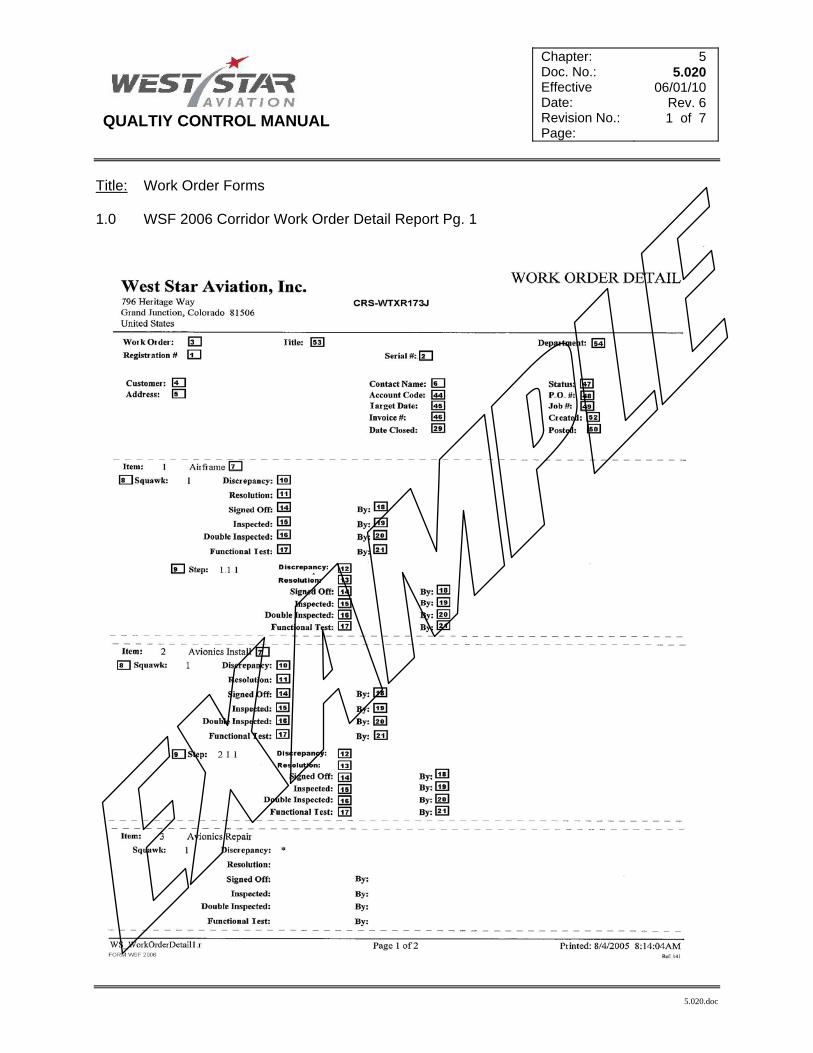
QUALTIY CONTROL MANUAL
Chapter: Doc. No.: Effective Date: Revision No.: Page:
5 5.020
06/01/10 Rev. 6 1 of 7
5.020.doc
Title: Work Order Forms 1.0 WSF 2006 Corridor Work Order Detail Report Pg. 1

QUALTIY CONTROL MANUAL
Chapter: Doc. No.: Effective Date: Revision No.: Page:
5 5.020
06/01/10 Rev. 6 2 of 7
5.020.doc
2.0 WSF 2006 Corridor Work Order Detail Report Pg. 2

QUALTIY CONTROL MANUAL
Chapter: Doc. No.: Effective Date: Revision No.: Page:
5 5.020
06/01/10 Rev. 6 3 of 7
5.020.doc
3.0 WSF 2007 Corridor Work Order Squawk Report

QUALTIY CONTROL MANUAL
Chapter: Doc. No.: Effective Date: Revision No.: Page:
5 5.020
06/01/10 Rev. 6 4 of 7
5.020.doc
4.0 WSF 2008 Corridor Work Order Step Report

QUALTIY CONTROL MANUAL
Chapter: Doc. No.: Effective Date: Revision No.: Page:
5 5.020
06/01/10 Rev. 6 5 of 7
5.020.doc
5.0 Form WSF.2000 – Work Order Form First Page NOTE: The WSF.2000 & .2001 Work Order forms are only to be used as a backup if the computer system fails. It also may be use in the case of weekend drop-ins or after regular business hours. An aircraft can be returned to service using these forms as described in this chapter. The information contained on these forms will be transcribed into the Corridor system as soon as practical.

QUALTIY CONTROL MANUAL
Chapter: Doc. No.: Effective Date: Revision No.: Page:
5 5.020
06/01/10 Rev. 6 6 of 7
5.020.doc
6.0 Form WSF.2001 – Work Order Form Continuation Page

QUALTIY CONTROL MANUAL
Chapter: Doc. No.: Effective Date: Revision No.: Page:
5 5.020
06/01/10 Rev. 6 7 of 7
5.020.doc
7.0 Form WSF 018 – Inspection Job Aid To be used as a tool to initially document work order squawks. This form will be discarded once squawks have been entered into the work order.

QUALITY CONTROL MANUAL
Chapter: Doc. No.: Effective Date: Revision No.: Page:
5 5.021
06/01/10 Rev. 6 1 of 4
5.021.doc
Title: Work Order Forms Instructions for the Corridor system 1.0 Instructions for Completion of Work Order Forms
1.1 The following table shows the definition of each block/space located on the forms listed below. Form samples can be located on doc. No. 5.020 in the QCM.
WSF 2006 Work Order Detail Report (Corridor Report) WSF 2007 Work Order Squawk Report (Corridor Report) WSF 2008 Work Order Step Report (Corridor Report)
1.2 Each number in the first column on the following table corresponds to a number
located in one of the block/space on the sample Corridor forms located in document pages 5.020 in this manual. The numbers in the first column in the following table of instructions may not be sequential. The Corridor system generates these forms automatically and the block/space’s defined in the following table are auto-filled by the Corridor system based on data entry by whom ever is logged in or whom ever has scanned into the system in regards to labor or squawk/step sign-offs.
1 Reg.#: Aircraft Registration number
2 Serial #: Aircraft Serial number
3 Work Order: Work Order number
4 Customer: Customer name
5 Address: Customer address, typically for billing purposes
6 Contact Name: Contact name for the customer
7 Item: Created in the Corridor system relating to a department. Squawks are then created under the ITEMS.
8 Squawk: Created after the ITEM. The squawk will consist of the Discrepancy, Resolution, required Inspections and the dates those inspections where signed off electronically. Note: Squawk numbers are automatically generated by the Corridor system relating to the ITEM number. Example- 1. Airframe (Item) 1.1 Phase B (Squawk)
9 Steps: Created after the Squawk as required to document progressive steps for the resolution. Steps will be signed off in the same manner as squawks, electronically. Note: Step numbers are automatically generated by the Corridor system relating to the ITEM number. Example- 1. Airframe (Item) 1.1 Phase B (Squawk) 1.1.1 Ok to close (Step)

QUALITY CONTROL MANUAL
Chapter: Doc. No.: Effective Date: Revision No.: Page:
5 5.021
06/01/10 Rev. 6 2 of 4
5.021.doc
10 Discrepancy: Enter the discrepancy. Discrepancies are discovered through logbook research, visual inspection, or verbal discussion with the Owner/Operator. When entering discrepancies into the Corridor system, use a description, which completely describes the problem. If the problem is complex, a separate discrepancy will need to be written for each specific problem. When entering discrepancies that have been obtained from the operator of the aircraft, the discrepancy must be entered using the operator’s exact description. When visual inspection or troubleshooting reveals that the operators’ discrepancy differs from his description or a more specific problem is discovered, the discrepancy must be further explained. When a discrepancy calls for a routine inspection item to be accomplished, the description in the discrepancy field will describe the inspection to be accomplished and the interval at which the inspection is required. When a discrepancy calls for compliance with an Airworthiness Directive or Service Bulletin, its description must contain the identifying number, the manufacturer to whom the Directive or Bulletin applies, a description of the subject of the Directive or Bulletin, the date of issue and, if the Directive or bulletin is recurring, the interval of occurrence.
11 Resolution: Enter the action taken to correct the discrepancy. The resolution field of the work order must be completed at the time that the work is accomplished. The technician performing the work must enter a clear, concise description of the work performed to correct the discrepancy. The resolution field must also describe, step by step, the troubleshooting action that took place when applicable. If the person beginning the work does not complete the work, he/she must describe the work performed and enter their initial and date at the end of his/her entered description. Or move their work description to a “Step” under the same squawk. This will allow an individual sign-off for that portion of the resolution.
12 (Step) Description: Enter the description as a “Discrepancy” of the step being performed. A step is a progressive sign off to the resolution of the squawk.
13 (Step) Comments: Enter comments as a “Resolution” to the step being performed.
14 Sign-off: Displays the date the technician electronically “Signed off” the squawk/step.
15 Inspected: Displays the date the technician electronically signed off the “Single Inspection” requirement of the squawk/step.
16 Double Inspected: Displays the date the Quality Assurance Inspector electronically signed off the “Double Inspected” requirement of the squawk.
17 Functional Test: Displays the date the technician electronically signed off the “Functional Test” for the squawk.
18 Signed off By: Displays the name of the technician that electronically signed-off the squawk/step.
19 Inspected By: Displays the name of the technician that electronically signed-off single inspection requirement of the squawk/step.
20 Double Inspected By: Displays the name of the technician that electronically signed-off double inspection requirement of the squawk.

QUALITY CONTROL MANUAL
Chapter: Doc. No.: Effective Date: Revision No.: Page:
5 5.021
06/01/10 Rev. 6 3 of 4
5.021.doc
21 Functional Test By: Displays the name of the technician that electronically signed-off the functional test requirement of the squawk/step.
22 Part Number Off: Displays the Part Number of the component removed if required in the squawk.
23 Part Description Off: Displays the description of the part removed
24 Serial Number Off: Displays the Serial number removed
25 Part Number On: Displays the Part Number of the component installed.
26 Part Description On: Displays the description of the part installed
27 Serial Number On: Displays the Serial number installed.
28 Date Opened: Displays the date the Work Order was opened.
29 Date Closed: Displays the date the Work Order was closed.
30 Opened by: Displays who opened the work order
31 Completed by: Displays who completed the squawk. Invoicing only.
32 Contact telephone: Displays customer contact telephone number
33 Manufacture: Displays manufacture of article the squawk was written for.
34 Aircraft total time: Displays aircraft total time
35 Part/Model number: Displays Part/Model number of article the squawk was written for.
36 Total time: Note used at this time. Future enhancement
37 Total cycles: Note used at this time. Future enhancement
38 TSN/TSO: Note used at this time. Future enhancement
39 CSN/CSO: Note used at this time. Future enhancement
40 Page number: Displays page number of squawk
41 Printed: Displays the date the squawk was printed
42 Date in: Displays the date the article was scheduled to arrive at West Star Aviation
43 Date out: Displays the date the article was scheduled to depart/deliver from West Star Aviation

QUALITY CONTROL MANUAL
Chapter: Doc. No.: Effective Date: Revision No.: Page:
5 5.021
06/01/10 Rev. 6 4 of 4
5.021.doc
44 Account code: Displays account code assigned to the customer.
45 Target date: Displays the target date the article is expected to be completed.
46 Invoice #: Displays the invoice number.
47 Status: Displays the status of the work order. Either Open, Preliminary or Closed.
48 PO#: Note used at this time. Future enhancement
49 Job #: Note used at this time. Future enhancement
50 Posted: Displays the date the work order was posted in accounting
51 Barcode: Scanned by technician when trying to sign off/Inspect a squawk/step or add labor to that squawk/step.
52 Created: Displays the date the Work Order Detail report was created.
53 Title: Displays info specific to the work order. A required field with optional content
54 Department: Display the department that originally opened the work order
NOTE: Ref. Advisory Circular 43.9 as revised. “14CFR 91.417(a)(1)(i) requires that the
maintenance record entry to include, “A description of the work performed”. The description should be in sufficient detail to permit a person unfamiliar with the work to understand what was done, and the methods and procedures used in doing it. To provide for this contingency, the rule permits reference to technical data acceptable to the administrator in lieu of making a detailed entry.

QUALITY CONTROL MANUAL
Chapter: Doc. No.: Effective Date: Revision No.: Page:
5 5.022
07/01/07 Rev. 3 1 of 7
5.022
Title: Work Order Forms Instructions
NOTE: The WSF.2000 & .2001 Work Order forms are only to be used as a backup if the computer system is unavailable. It also may be use in the case of weekend drop-ins or after regular business hours. An aircraft can be returned to service using these forms as described in this chapter. The information contained on these forms will be transcribed into the Corridor system as soon as practical.
1.0 Instructions for Completion of Work Order Forms
1.1 The following table of instructions describes the completion of West Star Aviation, Inc. work order forms, as listed below. Form samples can be located on doc. No. 5.020 in the QCM.
WSF.2000 WSF.2001
1.2 Each item number corresponds to a number located in one of the blanks on the
sample work order forms, located on the previous pages. The items numbers in the following table of instructions may not be sequential. The blanks, which must be completed, on each work order, are identified by (*) next to the instruction for that item. If a required blank (marked with (*)) is not applicable to the work being accomplished it must be marked as N/A or a line drawn through. Those items identified by () are additional items must be completed on Forms WS2000 if an inspection, which is part of the aircraft’s inspection/maintenance program, is being documented, on that particular work order.
* 1 Enter the work order number assigned to the job.
* 2 Enter the registration number of the aircraft to which the work order is opened.
* 3 Enter the total number of pages contained in the work order upon completion of the job.
* 4 Enter the customer and or contact name.
5 Enter the customer’s permanent mailing address.
6 Enter the phone number at which the customer can be reached while the aircraft/engine is in work.
* 7 Enter the make and model of the aircraft/engine to which the work order has been opened, (i.e. Cessna 650, Lear 35A, Garrett 331-10).
* 8 Enter the complete serial number of the aircraft/engine to which the work order has been opened, (i.e. 35A-433, 650-0234, P89778)

QUALITY CONTROL MANUAL
Chapter: Doc. No.: Effective Date: Revision No.: Page:
5 5.022
07/01/07 Rev. 3 2 of 7
5.022
* 9 Enter the date the aircraft/engine is scheduled to arrive at the facility for work.
* 10 Enter the date the aircraft/engine is scheduled to leave West Star (Promised), following completion of the job.
11 Enter the aircraft/engine total time in service.
* 12 Enter the aircraft tach.. time if the aircraft is so equipped.
* 13 Enter the aircraft hour meter reading if the aircraft is so equipped.
14 Enter the total number of landings the aircraft has accumulated since new. (Required only if the aircraft inspection/maintenance program requires scheduled maintenance or inspection at specific cycle or landing frequencies).
* 15 To be initialed by the repair station inspector performing the preliminary inspection of the aircraft/article as required by the Repair Station Inspection Procedures Manual (Chapter 3.030 para. 3.1.1), prior to beginning the work scope.
* 16 To be initialed by the repair station inspector performing the hidden damage inspection. This inspection is required only on aircraft/articles tthhaatt have been involved in an accident. If the aircraft/article has not been involved in an accident, this block must be marked N/A Ref. Chapter 3.030 para. 3.1.2 of this manual.
* 17 To be initialed by the quality assurance department personnel once the aircraft maintenance record entries have been completed to indicate that the aircraft or maintenance has been properly approved for return to service.
* 18 To be initialed by quality assurance department personnel once each discrepancy on the work order has been reviewed and initialed (Block 46), and all of the supporting documentation (i.e. inspection guides, run sheets etc.) have been reviewed and compiled. Initialing of this block by quality assurance personnel indicates the work package is complete and ready for filing.
19 Enter the model number of the engine in the blank to the right of the number corresponding to the engine position. (Determine engine position number by counting from left = 1 to right = 2 when sitting in the pilot seat).
20 Enter the serial number of the engine in the blank to the right of the number corresponding to the engine position. (Determine engine position number by counting from left = 1 to right = 2 when sitting in the pilot seat).
21 Enter the total time of the engine in the blank to the right of the number corresponding to the engine position. (Determine engine position number by counting from left = 1 to right = 2 when sitting in the pilot seat).
22 Enter the total cycles accumulated on the engine in the blank to the right of the number corresponding to the engine position. (Determine engine position number by counting from left = 1 to right = 2 when sitting in the pilot seat).

QUALITY CONTROL MANUAL
Chapter: Doc. No.: Effective Date: Revision No.: Page:
5 5.022
07/01/07 Rev. 3 3 of 7
5.022
23 Enter the model number of the propeller in the blank to the right of the number corresponding to the propeller position. (Determine Prop position number by counting from left = 1 to right = 2 when sitting in the pilot seat).
24 Enter the serial number of the propeller in the blank to the right of the number corresponding to the propeller position. (Determine Prop position number by counting from left = 1 to right = 2 when sitting in the pilot seat).
25 Enter the total time of the propeller in the blank to the right of the number corresponding to the propeller position. (Determine Prop position number by counting from left = 1 to right = 2 when sitting in the pilot seat).
26 Enter the total cycles accumulated on the propeller in the blank to the right of the number corresponding to the propeller position. (Determine Prop position number by counting from left = 1 to right = 2 when sitting in the pilot seat).
27 Enter the auxiliary power unit hour meter reading and /or cycles if so equipped.
28 Enter the aircraft heater hour meter reading if so equipped.
29 Enter the aircraft air conditioner hour meter reading if so equipped.
* 30 Enter the next sequential discrepancy number. Various squawk numbering schemes are in place for each West Star Department. Supervisory personnel are familiar with the correct squawk numbering procedures for their respective departments.
* 31 Enter the work order number assigned to the job. This blank to be filled out to facilitate data entry by the billing department.
* 32 Enter the reference data used to complete the inspection/maintenance performed, when applicable.
* 33 Enter the discrepancy. Discrepancies are discovered through logbook research, visual inspection, or verbal discussion with the Owner/Operator. When writing discrepancies on the work order use a description, which completely describes the problem. If the problem is complex, a separate discrepancy will need to be written for each specific problem. When writing discrepancies that have been obtained from the operator of the aircraft, the discrepancy must be written using the operator’s exact description. When visual inspection or troubleshooting reveals that the operators’ discrepancy differs from his description or a more specific problem is discovered, the discrepancy must be further explained in the corrective action block (35). When a discrepancy calls for a routine inspection item to be accomplished, the description in the discrepancy block will describe the inspection to be accomplished and the interval at which the inspection is required. When a discrepancy calls for compliance with an Airworthiness Directive or Service Bulletin, its description must contain the identifying number, the manufacturer to whom the Directive or Bulletin applies, a description of the subject of the Directive or Bulletin, the date of issue and, if the Directive or bulletin is recurring, the interval of occurrence.
* 34 To be initialed by the person writing the discrepancy.

QUALITY CONTROL MANUAL
Chapter: Doc. No.: Effective Date: Revision No.: Page:
5 5.022
07/01/07 Rev. 3 4 of 7
5.022
* 35 Enter the action taken to correct the discrepancy. The corrective action block of the work order must be completed at the time that the work is accomplished. The technician performing the work must write a clear, concise description of the work performed to correct the discrepancy. The corrective action block must also describe, step by step, the troubleshooting action that took place when applicable. If the person beginning the work does not complete the work, he/she must describe the work performed and initial and date the end of his/her written description. When the space provided in the corrective action block is not sufficient to describe the work performed, a supplemental corrective action sheet (form WS2002) will be used. When a supplemental corrective action sheet is used, the “Supp Box” located in the corrective action block on the original discrepancy should be marked with an x or a checkmark to indicated further information exists
* 36 To be initialed by the technician or inspector performing the functional test. The functional test must be performed whenever work has been performed on a system and the proper operation of that system may have been effected by the work performed. The functional test must be performed in accordance with the instructions of the manufacturer contained in the maintenance manual. In the event that more than one functional test must be performed, or the corrective action requires functional tests at various stages of the work process, each individual functional test shall be noted in block 35 and initialed by the person performing the functional test. The last functional test must be indicated using the F/T block (36). When a functional test is not required this block must be marked “N/A” by the repair station inspector performing the final inspection for that discrepancy.
* 37 To be initialed by the technician who completes the work. This block may be left blank only if the technician has initialed and dated within the corrective action, if the inspection truly requires only one set of eyes and that would be the final inspector and if the technician(s) are able to initial using an inspection checklist.
* 38 To be used only when two phases of closure exist as a part of the corrective action. An example of two phases of closure is when a landing gear gearbox is reinstalled. The first repair station inspector must look at the installation of the gearbox and make the determination that the box and the area surrounding the box are satisfactory, and “OK to Close”. The second phase comes after the cover panels have been reinstalled and work on the area is completed. When the “OK to Close” box is used, we are assured that the items, which are no longer visible, have been properly inspected, and conform to the requirements of the FAA for progressive inspections. When this progressive inspection is not necessary, this block must be marked “N/A” by the repair station inspector performing the final inspection for that discrepancy.
* 39 To be initialed by the repair station inspector approving the item for return to service. It is the responsibility of the person initialing this block to assure all work, including the documentation of the discrepancy and corrective action for the discrepancy, has been accomplished properly.
* 40 Enter the date the work was accomplished. This is the date the final inspection was completed for the item.

QUALITY CONTROL MANUAL
Chapter: Doc. No.: Effective Date: Revision No.: Page:
5 5.022
07/01/07 Rev. 3 5 of 7
5.022
* 41 Enter the part number of the component removed.
* 42 Enter the serial number of the component removed.
* 43 Enter the part number of the component installed, when applicable.
* 44 Enter the serial number of the component installed, when applicable.
* 45 To be initialed by Quality Assurance Inspector if a log book entry is warranted and completed. If a log book entry is not warranted, “NA” will be placed here.
* 46 To be initialed by a Quality Assurance Inspector upon satisfactory review of the discrepancy for accuracy and completeness. The discrepancy must be completed and final inspection accomplished by appropriately authorized repair station inspector.
* 47 Enter the date that the page was opened for the work order. The date the first item was entered on that page.
* 48 Enter the page number for that page.
49 Mark with an x or check mark to indicate that a supplemental work order sheet (form WS2002) has been used to continue the corrective action description.
* 50 Enter the date that the supplemental work was accomplished.
* 52 Enter the customer’s purchase order number.
* 53 Work Scope / Work Instructions – check the appropriate item that best describes the work to be performed.
* 57 Enter the appropriate nomenclature describing the component to be repaired/overhauled.
* 58 Enter the part number of the component to be repaired/overhauled.
* 59 Enter the model number of the component to be repaired/overhauled.
* 60 Enter the serial number of the component to be repaired/overhauled.
* 61 Enter any out of the ordinary discrepancies noted during the disassembly process. Check for compliance with applicable Service Bulletins and Airworthiness Directives. Indicate verification of Service Bulletin and Airworthiness Directive status by checking the appropriate blocks. See item 62.
* 62 Mark off each block, as appropriate, following verification of Service Bulletin and Airworthiness Directive Status. Record any compliance requirements in the Work Instructions Block of the work order.
* 63 Record the results of functional tests made as required by the appropriate repair or overhaul instructions.

QUALITY CONTROL MANUAL
Chapter: Doc. No.: Effective Date: Revision No.: Page:
5 5.022
07/01/07 Rev. 3 6 of 7
5.022
* 64 Enter the date of completion of the work described. To be dated by the technician initialing the appropriate Tech block.
65 Enter the hours worked in order to complete the work.
* 66 When Avionics performs a functional test of equipment in aircraft to verify discrepant operation, the technician performing the work will place a check or X in the box next to “Ramp Check” and the appropriate additional box on that line to indicate the results of the functional test.
* 67 When equipment is removed, from the aircraft to be repaired, the technician removing the equipment will place a check or X in the box next to “removed” and record the part number(s) and serial number(s) of the equipment in the blanks provided.
* 68 When equipment is certified in the aircraft the technician will place a check or X in the box next to “certified” and record the part number(s) and serial number(s) of the equipment in the blanks provided. A record of the certification is then made in the aircraft tech notes section.
* 69 When rental or loaner equipment is installed in the aircraft to replace the equipment removed, the technician installing the equipment will place a check or X in the box next to “installed”. He or she will then indicate the equipment is either loaner or rental equipment, and record the purchase order number(s), part number(s) and serial number(s) for the installed equipment in the blanks provided.
* 70 Aircraft Tech Notes is the section for the technician to record the details of repairs made to correct the discrepancy without removing the equipment. This may include troubleshooting notes and wire or mounting repairs, circuit breaker replacement, and the like. When additional space is required for aircraft tech notes, the space is continued on the reverse side of the form. ( ) are placed around notes and descriptions that are not intended to be part of the invoice for the customer which is generated from the notes. The boxes at the bottom of the section are to be checked as appropriate to indicate successful completion of a second ramp check, appropriate maintenance record entries or reference to the tech notes for other disposition.
* 71 When Avionics performs a functional test of discrepant equipment using the avionics test bench equipment to verify discrepant operation this section is used. The technician performing the work will place a check or X in the box next to “Bench Check” and the appropriate additional box on that line to indicate the results of the functional test.
* 72 Bench Tech Notes is the section for the technician to record the details of repairs made to correct equipment discrepancies. When additional space is required for aircraft tech notes, the space is continued on the reverse side of the form. ( ) are placed around notes and descriptions that are not intended to be part of the invoice for the customer which is generated from the notes. The boxes at the bottom of the section are to be checked as appropriate to indicate parts have been ordered and whether or not exchange or loaner equipment was issued.

QUALITY CONTROL MANUAL
Chapter: Doc. No.: Effective Date: Revision No.: Page:
5 5.022
07/01/07 Rev. 3 7 of 7
5.022
* 73 When parts are ordered, including exchange equipment, the parts detail is recorded as appropriate in this area. The boxes at the bottom of this section are to be completed to indicate mod status, completion of appropriate alignment procedures and reference to tech notes as required.
* 74 This area is used to indicate what was re-installed in the aircraft following the work. The technician will place a mark in the box next to “installed” and then in the appropriate box to indicate the condition of the unit being installed. The technician will then record the part number(s) and serial number(s) of the equipment in the blanks provided.
75 The pricing of parts used and the total number of hours used to complete the work are placed on this line.
76 To be initialed by a Category I inspector, if the maintenance or inspection described in the item includes a Critical Inspection item. Reference West Star Certified Procedure CP 1.004 for the definition of a Critical Inspection item. If the item does not include Critical Inspection items, this block should be marked “N/A” by the repair station inspector performing the final inspection for that discrepancy.
77 While performing maintenance, some items will require multiple inspections during the progression of the corrective action. When an individual inspector completes a necessary inspection, he or she may write a description of the inspection, then initial and date the end of his/her written description.
* Note Upon the completion of any and all maintenance and or inspection, Form/Sticker
F080 will be placed after the last discrepancy/corrective action, signed by the Authorized QC Inspector and Quality Assurance Inspector for final return to service for the work performed.

QUALITY CONTROL MANUAL
Chapter: Doc. No.: Effective Date: Revision No.: Page:
5 5.030
03/01/14 Rev.9 1 of 6
5.030 Rev. 9.doc
Title: REPAIR STATION RETURN TO SERVICE FORMS 1.0 Purpose:
1.1 The purpose of this chapter is to prescribe the methods and practices for return to service forms.
2.0 Responsibilities
2.1 All personnel involved in creating, revising or using return to service forms will be familiar with the contents of this section.
2.2 The Quality Assurance Manager or his designee shall:
2.2.1 Review each new or revised form before use. 2.2.2 Add the form to the Forms Data Base. 2.2.3 Assure that a copy of the updated Forms data base via CD or Thumb drive is provided to
the Flight Standards District Office (FSDO) at least once a month.
3.0 Form F080 – “145 Sticker” Approval for Return to Service
This stamp/sticker is placed after the last discrepancy of the work order. Signature by the
QA inspector indicating that the work order has been reviewed and that all corrective actions are adequate, all required signatures are in place and that all other required information is contained in the work order. The QC Inspectors signature indicates that all work is complete, all required inspections and/or maintenance have been performed and that the aircraft is airworthy and approved for returned to service with respect to the work performed. The completion of this sticker in conjunction with the log entry sign off will be used as the primary means for this repair station returning an aircraft, airframe, aircraft engine, propeller, appliance or component part to service.
I certify that the above stated maintenance and/or inspection was performed in accordance with the current regulations of the FAA and the aircraft, engine, prop or component identified above was determined to be in an airworthy
condition and approved to return to service with respect to the work performed.
FAA CRS WTXR173J Date___________________
Signed (QC)_______________________________________
Signed (QA)_______________________________________
F080-09/04

QUALITY CONTROL MANUAL
Chapter: Doc. No.: Effective Date: Revision No.: Page:
5 5.030
03/01/14 Rev.9 2 of 6
5.030 Rev. 9.doc
3.1 Form F081 – “145 Sticker” Not Approved for Return to Service
This label is attached after the last discrepancy of the work order. The QC and QA Inspector’s signatures indicate that all maintenance and/or inspection was completed, but the aircraft, airframe, aircraft engine, propeller, appliance or component part is not eligible for approval for return to service by the repair station.
I certify that the above stated maintenance and/or inspection was performed in accordance with the current regulations of the Federal Aviation Administration and a
signed list of discrepancies and unairworthy items has been given to the aircraft owner or operator.
FAA CRS WTXR173J Date___________________
Signed (QC)_______________________________________
Signed (QA)_______________________________________ F081-9/04
3.2 Form F1002 – “OCF Sticker” Operational Check Flight
If required, after completion of maintenance, repair or alteration make an entry into the work order discrepancy block stating, “Operational Check Flight Due”. In the corrective action, state, “Reference aircraft log books, dated ________, for OCF sign off”. This label will be placed in the aircraft logbooks after the last log entry, if required. The Pilot signature & Cert. # indicates a satisfactory completion of the OCF. FAA guidelines for this requirement can be found in 14 CFR 91.407
OPERATIONAL CHECK FLIGHT West Star Aviation, Inc.-CRS# WTXR173J
Date______________ Performed Operation Check Flight and found the aircraft to be in a satisfactory condition.
Please reference West Star Aviation WO# ______________ for details of maintenance performed.
Pilot Signature _________________________
Cert. #_________________________ F1022

QUALITY CONTROL MANUAL
Chapter: Doc. No.: Effective Date: Revision No.: Page:
5 5.030
03/01/14 Rev.9 3 of 6
5.030 Rev. 9.doc
3.3 FAA Form 8130-3, Authorized Release Certificate
3.3.1 West Star personnel may use FAA Form 8130-3 as an approval for return to service, in place of West Star form WS2163, when approving articles for return to service following maintenance, preventive maintenance, repair or alteration.
3.3.2 FAA Form 8130-3 can only be signed off by Return to Service authorized Category 1 QC Inspectors.
3.3.3 Pages 5 through 7 of this document explain in detail the appropriate procedures in filling
out this form. These procedures were derived from FAA Order 8130-21, as revised.

QUALITY CONTROL MANUAL
Chapter: Doc. No.: Effective Date: Revision No.: Page:
5 5.030
03/01/14 Rev.9 4 of 6
5.030 Rev. 9.doc

QUALITY CONTROL MANUAL
Chapter: Doc. No.: Effective Date: Revision No.: Page:
5 5.030
03/01/14 Rev.9 5 of 6
5.030 Rev. 9.doc
BLK # Appropriate Contents on FAA form 8130-3
1 Approving National Aviation Authority/Country: FAA/United States (Preprinted)
2 Authorized Release Certificate, FAA form 8130-3, Airworthiness Approval Tag. (Preprinted)
3
Form Tracking Number: The number will be unique to each serialized component and be comprised of the Work Order number, a dash (-) followed by the squawk or step number. One squawk in the work order per serialized component unless the P/N in Blk. 8 comprises many serialized parts to make a kit/set. In this case, create an attachment to the 8130-3 listing all serialized components of the same P/N.
4 Organization Name and Address: West Star Aviation, Inc. 796 Heritage Way Grand Junction, CO 81506, FAA Repair Station #: WTXR173J. (Preprinted)
5 Work Order/Contract/Invoice Number: West Star Aviation Work Order number corresponding to the work scope.
6 Item: West Star is only authorized to use this form for approval for return to service and only allowed to issue 1ea 8130-3 for “1” P/N at a time. (Preprinted).
7 Description: Enter the name or description of the product, part or appliance as referenced in a part catalog or overhaul manual.
8 Part Number: Enter part number of the product or article. ONE part number per one 8130-3. If the article being worked is a subassembly that does not have a part number of its own, enter the next higher assembly number followed by the word “subassembly.”
9 Quantity: Enter “1” unless there are multiple un-serialized components of the same P/N in Blk. 8. Or multiple S/N’s of the same P/N that make up a kit/set.
10
Serial Number: If the product or article is required by part 45 to be identified with a serial number, enter it here. Additionally, any other serial number not required by regulation also may be entered. If no serial number is entered in this block, enter “N/A.” Multiple serial numbers can be entered here associated with one part number.
11
Status/Work. The following describes what to enter in a specific situation. Only one term may be entered in Block 11, which should reflect the majority of the work performed by West Star. “Overhauled”: A process that ensures the product or article is in complete
conformity with the applicable service tolerances specified in the type certificate manufacturer’s instructions for continued airworthiness, or in the data approved or accepted by the authority. The product or article will be at least disassembled, cleaned, inspected, repaired as necessary, reassembled, and tested in accordance with the approved or accepted data.
“Repaired”: Repair of defect(s) using an applicable standard. “Inspected” and/or “Tested”: Examination or measurement in accordance with an
applicable standard (for example, visual inspection, functional testing, or bench testing).
“Modified”: Alteration of a product or article to conform to an applicable standard. NOTE: The applicable standard must be described in Block 12.

QUALITY CONTROL MANUAL
Chapter: Doc. No.: Effective Date: Revision No.: Page:
5 5.030
03/01/14 Rev.9 6 of 6
5.030 Rev. 9.doc
12
Remarks: Describe the work identified in Block 11 and associated results necessary for the user or installer to determine the airworthiness of the product or article in relation to the work being certified. Example: “Overhauled in accordance with CMM ---, Section---, Manual---, Revision---, and AD reference where applicable. If necessary, a separate sheet may be used and referenced from the main FAA Form 8130-3. Each statement must clearly identify which product or article in Block 6 it relates to. NOTE: THE APPLICABLE STANDARD MUST BE DESCRIBED IN THIS BLK.
13a-13e
Blocks 13a through 13e: Shade, darken, or otherwise mark to preclude inadvertent or unauthorized use, (For original manufacturer of new components only).
14a Approval for Return to Service. Both boxes are to be checked for a valid dual release.
14b
Authorized Signature. This space will be completed with the signature of the authorized person. Only persons specifically authorized and listed on the West Star Aviation roster are permitted to sign this block. The approval signature must be applied at the time and place of issuance and manually applied.
14c Approval/Certificate No. Enter the West Star air Agency Certificate number: WTXR173J.
14d Enter the typed or printed name of the authorized representative whose signature appears in Block 14b.
14e
Date (dd/mmm/yyyy). The date to be entered in Block 14e for approval for return to service will be the date on which the original work was completed. The date must be in the following format: two-digit day, first three letters of the month, and four-digit year, for example, 03/FEB/2008.

QUALITY CONTROL MANUAL
Chapter: Doc. No.: Effective Date: Revision No.: Page:
5 5.040
07/01/07 Rev. 3 1 of 6
5.040.doc
Title: LOG ENTRIES 1.0 Purpose:
1.1 The purpose of this chapter is to prescribe the methods and practices for log entries.
2.0 Responsibilities
2.1 All personnel involved in creating, revising or using log entries will be familiar with the contents of this section.
2.2 The Quality Assurance Manager or his designee shall:
2.2.1 Review each new or revised log entry before use.
3.0 Procedures: Log entry examples
3.1 Maintenance Record Entry – ELT Annual Inspection The following maintenance record entry is used to verify that the ELT system was tested to comply with the requirements of 14 CFR 91.207 (d). The entry may contain descriptions of other maintenance performed. This entry may only be signed by a Quality Control Inspector who has return to service authorization, as shown on the Roster of Inspection Personnel which can be found in the inspection office. The format of this entry is typical and may vary, if the required information is present.
N Number WO #: A/C MAKE/MODEL S/N: DATE: TTAF: LANDINGS: HOBBS: AVIONICS ENTRY Tested ELT system to comply with 14 CFR 91.207 (d). Unit meets manufacturer’s specifications. Checked antenna and G-switch. ELT battery expires: (date). I certify that this aircraft has been inspected as required by 14CFR §91.409 (f)(?), and has been determined to be in an airworthy condition and approved for return to service with respect to the work performed. Pertinent details are on file at this repair station under the above work order. Signature _____________________________________ FAA CERTIFIED REPAIR STATION WEST STAR AVIATION, INC. WTXR173J 796 Heritage Way Grand Junction, CO 81506 (970) 243-7500
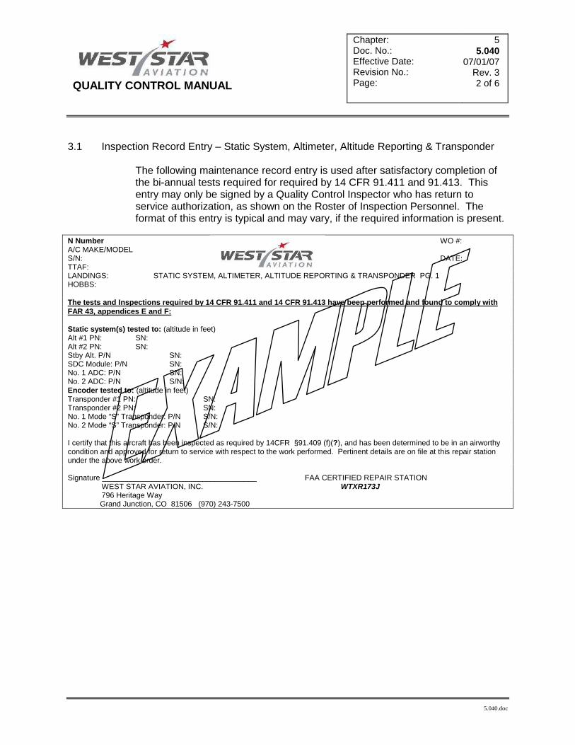
QUALITY CONTROL MANUAL
Chapter: Doc. No.: Effective Date: Revision No.: Page:
5 5.040
07/01/07 Rev. 3 2 of 6
5.040.doc
3.1 Inspection Record Entry – Static System, Altimeter, Altitude Reporting & Transponder
The following maintenance record entry is used after satisfactory completion of the bi-annual tests required for required by 14 CFR 91.411 and 91.413. This entry may only be signed by a Quality Control Inspector who has return to service authorization, as shown on the Roster of Inspection Personnel. The format of this entry is typical and may vary, if the required information is present.
N Number WO #: A/C MAKE/MODEL S/N: DATE: TTAF: LANDINGS: STATIC SYSTEM, ALTIMETER, ALTITUDE REPORTING & TRANSPONDER PG. 1 HOBBS: The tests and Inspections required by 14 CFR 91.411 and 14 CFR 91.413 have been performed and found to comply with FAR 43, appendices E and F: Static system(s) tested to: (altitude in feet) Alt #1 PN: SN: Alt #2 PN: SN: Stby Alt. P/N SN: SDC Module: P/N SN: No. 1 ADC: P/N SN: No. 2 ADC: P/N S/N: Encoder tested to: (altitude in feet) Transponder #1 PN: SN: Transponder #2 PN: SN: No. 1 Mode “S” Transponder: P/N S/N: No. 2 Mode “S” Transponder: P/N S/N: I certify that this aircraft has been inspected as required by 14CFR §91.409 (f)(?), and has been determined to be in an airworthy condition and approved for return to service with respect to the work performed. Pertinent details are on file at this repair station under the above work order. Signature _____________________________________ FAA CERTIFIED REPAIR STATION WEST STAR AVIATION, INC. WTXR173J 796 Heritage Way Grand Junction, CO 81506 (970) 243-7500

QUALITY CONTROL MANUAL
Chapter: Doc. No.: Effective Date: Revision No.: Page:
5 5.040
07/01/07 Rev. 3 3 of 6
5.040.doc
3.1 Inspection Record Entry – Static System, Altimeter, Altitude Reporting & Transponder
For Reduced Vertical Seperation (RVSM) The following maintenance record entry is used after satisfactory completion of tests for RVSM certification requirements. The format of this entry is typical and may vary dependent on the requirements of individual RVSM installations.
N Number WO #: A/C MAKE/MODEL S/N: DATE: TTAF: LANDINGS: HOBBS: REDUCED VERTICAL SEPARATION MINIMUMS (RVSM) Removed the following equipment; Installed the following equipment in accordance with Flight Test Associates, Inc. STC ST01524LA, ST01525LA and ST01526LA per FAA form 337 dated: Honeywell AZ-252 ADC, P/N: S/N: Honeywell BA-250 Altimeter, P/N: S/N: Honeywell AM-250 Altimeter, P/N: S/N: Honeywell AL-800 Altitude Preselect Controller, P/N: S/N: Aerosonic Standby Altimeter, P/N: S/N: Sandia SAS1-24 Diode Board, P/N S/N Rosemount Pitot/Static Probes (2 ea.), P/N: and S/N: and Note: Pitot / Static Probes are life limited at 10,000 hours. Removed and reinstalled Autopilot Computer, P/N: S/N: Removed and reinstalled Stab Actuator, P/N: S/N: Removed and reinstalled Pitch Servo, P/N: S/N: Removed and reinstalled pilot and co-pilots airspeed indicators P/N: S/N: and P/N: S/N after being modified per
drawing # 64373-148. The Tests and Inspections required by CFR 91.411 and CFR 91.413 have been performed and found to comply with Part 43, Appendices E & F and Certified to RVSM standards IAW ???? maintenance manual chapter ??? Rev. ???: Static system(s) and Automatic Pressure Altitude Reporting Equipment tested to: 45,000 Ft. Honeywell BA-250 Altimeter, P/N: 70310N01D01 S/N: Honeywell AM-250 Altimeter, P/N: 70257N01D01 S/N: Aerosonic Standby Altimeter, P/N: 16650-1150 S/N: Honeywell AZ-252 ADC, P/N: 7024900-30303 S/N: No.1 Transponder P/N: S/N: No.2 Transponder P/N: S/N: No.1 Mode S Transponder P/N: S/N: No.2 Mode S Transponder P/N: S/N: This RVSM requirement has been complied with by West Star Aviation by modification of the pitot-static and altimetry system and incorporation of the FAA approved Supplemental Type Certificates, (ST01524LA, ST01525LA and ST01526LA). These STC’s meet the requirements for the Design Data Package, specified in para. 9 of “14CFR §91-RVSM CHG. 1 Interim Guidance Material on the Approval of Operators/Aircraft for RVSM Operations”, dated June 6, 1999 and has been FAA approved. I certify the above-described alteration has been inspected/conformed and has been determined to be in an airworthy condition and is approved for return to service with regards to the work performed. Pertinent details are on file at this repair station under the above work order. Signature _____________________________________ FAA CERTIFIED REPAIR STATION WEST STAR AVIATION, INC. WTXR173J 796 Heritage Way Grand Junction, CO 81506 (970) 243-7500

QUALITY CONTROL MANUAL
Chapter: Doc. No.: Effective Date: Revision No.: Page:
5 5.040
07/01/07 Rev. 3 4 of 6
5.040.doc
3.2 Maintenance Record Entry – Static System Break-In
The following maintenance record entry is used after satisfactory completion of the tests required by 14 CFR 91.411 (a) (2) (b) for the opening and closing of static systems. The format of this entry is typical and may vary, if the required information is present.
N Number WO #: A/C MAKE/MODEL S/N: DATE: TTAF: LANDINGS: AVIONICS ENTRY PG. 1 The tests and inspections required by 14 CFR 91.411 (a) (2) (b) for the opening and closing of static systems have been performed as follows: - Static system(s) tested to (altitude in feet) All maintenance performed on this aircraft was performed in accordance with current regulations of the FAA and was determined to be in an airworthy condition and is approved for return to service with respect to the work performed. Pertinent details are on file at this repair station under the above work order. A copy of this work order has been given to the operator. Signature _____________________________________ FAA CERTIFIED REPAIR STATION WEST STAR AVIATION, INC. WTXR173J 796 Heritage Way Grand Junction, CO 81506 (970) 243-7500 3.3 Inspection Record Entry – Return to Service Following Inspection
The following maintenance record entry is used to return to service an aircraft after completion of an inspection, which is part of a current inspection program recommended by the manufacturer per the requirements of 14 CFR § 91.409 (f) (3). The type of inspection (100 hour, Phase A, Annual, etc.) is listed in the body of the entry. This entry may only be signed by a Quality Control Inspector who has return to service authorization, as shown on the Roster of Inspection Personnel. The format of this entry is typical and may vary, if the required information is present.
N Number WO #: A/C MAKE/MODEL S/N: DATE: TTAF: LANDINGS: (AIRFRAME, ENGINE, PROP OR COMPONENT) ENTRY PG. 1 (DESCRIPTION OF THE INSPECTION(S) AND MAINTENANCE PERFORMED) I certify that this (Aircraft, Engine, Prop or Component) has been inspected as required by 14 CFR 91.409 (f) (3), and has been determined to be in an airworthy condition and is approved for return to service with respect to the work performed. Pertinent details are on file at this repair station under the above work order. A copy of this work order has been given to the operator. Signature _____________________________________ FAA CERTIFIED REPAIR STATION WEST STAR AVIATION, INC. WTXR173J 796 Heritage Way Grand Junction, CO 81506 (970) 243-7500

QUALITY CONTROL MANUAL
Chapter: Doc. No.: Effective Date: Revision No.: Page:
5 5.040
07/01/07 Rev. 3 5 of 6
5.040.doc
3.3 Inspection Record Entry – Return to Service Following Inspection using an approved
aircraft inspection program. The following maintenance record entry is used to return to service an aircraft after completion of an inspection, using an approved aircraft inspection program approved under § 135.419 and currently in use by a person holding an operating certificate issued under part 135 per the requirements of §91.409 (f) (2). The type of inspection (100 hour, Phase A, Annual, etc.) is listed in the body of the entry. This entry may only be signed by a Quality Control Inspector who has return to service authorization, as shown on the Roster of Inspection Personnel. The format of this entry is typical and may vary, if the required information is present.
N Number WO #: A/C MAKE/MODEL S/N: DATE: TTAF: LANDINGS: (AIRFRAME, ENGINE, PROP OR COMPONENT) ENTRY PG. 1 (DESCRIPTION OF THE INSPECTION(S) AND MAINTENANCE PERFORMED) I certify that this (Aircraft, Engine, Prop or Component) has been inspected as required by 14 CFR 91.409 (f) (2), and has been determined to be in an airworthy condition and is approved for return to service with respect to the work performed. Pertinent details are on file at this repair station under the above work order. A copy of this work order has been given to the operator. Signature _____________________________________ FAA CERTIFIED REPAIR STATION WEST STAR AVIATION, INC. WTXR173J 796 Heritage Way Grand Junction, CO 81506 (970) 243-7500
3.6 Maintenance Record Entry – Return to Service Following Repair (Airframe)
The following maintenance record entry is used to return to service an aircraft after completion of repairs as required by 14CFR § 91.405. A description of the maintenance performed is listed in the body of the entry. This entry may only be signed by a Quality Control Inspector who has return to service authorization, as shown on the Roster of Inspection Personnel. The format of this entry is typical and may vary, if the required information is present.
N Number WO #: A/C MAKE/MODEL S/N: DATE: TTAF: LANDINGS: (AIRFRAME, ENGINE, PROP OR COMPONENT) ENTRY PG. 1 (DESCRIPTION OF THE MAINTENANCE PERFORMED) All maintenance performed on this (Aircraft, Engine, Prop or Component) was performed in accordance with current regulations of the FAA and was determined to be in an airworthy condition and is approved for return to service with respect to the work performed. Pertinent details are on file at this repair station under the above work order. A copy of this work order has been given to the operator. Signature _____________________________________ FAA CERTIFIED REPAIR STATION WEST STAR AVIATION, INC. WTXR173J 796 Heritage Way

QUALITY CONTROL MANUAL
Chapter: Doc. No.: Effective Date: Revision No.: Page:
5 5.040
07/01/07 Rev. 3 6 of 6
5.040.doc
Grand Junction, CO 81506 (970) 243-7500
3.9 Record Entry – Unapproved for Return to Service Following Maintenance/Inspection for aircraft engine, propeller, or component.
The following record entry is used upon completion of maintenance and or Inspection, but the aircraft, airframe, aircraft engine, propeller, appliance or component part is not eligible for approval for return to service by the repair station as required by 14CFR § 43.11 (a)(5).
MAKE POSITION # MODEL A/C MAKE MODEL SN: N TSN: HR. MTR: CSN: TTAF: O/H DATE: (AIRCRAFT, ENGINE, PROP OR COMPONENT) LANDINGS: (DESCRIPTION OF THE MAINTENANCE PERFORMED) I certify that the above stated maintenance and or inspection was performed in accordance with the current regulations of the Federal Aviation Administration and a signed and dated list of discrepancies and unairworthy items has been provided for the aircraft owner or operator. Pertinent details are on file at this repair station under the above work order. A copy of this work order has been given to the operator. Signature _____________________________________ FAA CERTIFIED REPAIR STATION WEST STAR AVIATION, INC. WTXR173J 796 Heritage Way Grand Junction, CO 81506 (970) 243-7500 4.0 Maintenance Record Entry – Return to Service Following any Inspection
Those maintenance record entries’s used for return to service following any inspection must be specific in the body of the return to service statement as to which approved maintenance program was utilized and inserted between the parenthesis as depicted in the examples above.
NOTE: If the aircraft is being inspected under an “Approved Aircraft Inspection Program” the FAR
reference in the return to service statement on the log entry must be changed to 14CFR §91.409 (f) (2) and the log entry must state which AAIP.

QUALITY CONTROL MANUAL
Chapter: Doc. No.: Effective Date: Revision No.: Page:
5 5.050
01/01/12 Rev. 7 1 of 10
5.050.doc
Title: REPAIR STATION TAGS 1.0 Purpose:
1.1 The purpose of this chapter is to prescribe the methods and practices for the use of repair station tags.
2.0 Responsibilities
2.1 All personnel involved in using repair station tags will be familiar with the contents of this section.
2.2 The Quality Assurance Manager or his designee shall:
2.2.1 Review each new or revised tag before use. 3.0 Procedures: Repair Station Tag examples
3.1 Form WSF 150 – On-the-Job-Training This form is utilized to document internal training received coincidental to daily job task assignments (on the job) or classroom training, which is conducted in-house.

QUALITY CONTROL MANUAL
Chapter: Doc. No.: Effective Date: Revision No.: Page:
5 5.050
01/01/12 Rev. 7 2 of 10
5.050.doc
3.2 F.026 – Maintenance Release Sheet (Tag)
West Star Aviation, Inc. form F.026 is used to caution persons entering the aircraft, for any purpose, that the aircraft is currently undergoing maintenance and is not safe for operation. One sheet is issued to the aircraft and placed on or in the aircraft by a QA Inspector or his designee prior to maintenance. The sheet needs to be placed so it is obvious to any person who might attempt to operate the aircraft. The F.026 form is fluorescent orange in color to provide for quick detection. The aircraft may have multiple Work Orders opened against it. All departmental work orders will be listed on this sheet and will be cleared by Quality Assurance for the Operational Check Flight (OCF), if the OCF is required, by initialing in the Operational Check Flight box. The Sheet will remain in the aircraft during the OCF. Once the OCF is completed, any additional discrepancies will be cleared by QA and then Delivery box will be initialed by QA.

QUALITY CONTROL MANUAL
Chapter: Doc. No.: Effective Date: Revision No.: Page:
5 5.050
01/01/12 Rev. 7 3 of 10
5.050.doc
3.3 Tag WS2172 – Altimeter Correction Card Used to record variations found during altimeter certification process. A completed copy of this tag is issued with the altimeter upon completion of the certification process.

QUALITY CONTROL MANUAL
Chapter: Doc. No.: Effective Date: Revision No.: Page:
5 5.050
01/01/12 Rev. 7 4 of 10
5.050.doc
3.4 Tag WS2173 – Airspeed Correction Card
Used to record differences in readings found between calibrated test box and the airspeed in question during a variation inspection of airspeed indication devices. A completed copy of this form is provided with the air speed indicator, if the indicator is returned to the customer separate from the aircraft. If the air speed indicator is installed in the aircraft by West Star Aviation, then a copy of this form shall be given to the owner/operator of the aircraft.

QUALITY CONTROL MANUAL
Chapter: Doc. No.: Effective Date: Revision No.: Page:
5 5.050
01/01/12 Rev. 7 5 of 10
5.050.doc
NOT USED

QUALITY CONTROL MANUAL
Chapter: Doc. No.: Effective Date: Revision No.: Page:
5 5.050
01/01/12 Rev. 7 6 of 10
5.050.doc
3.6 Tag WS2161 – Repairable Part Tag
West Star Aviation, Inc. form WS2161 is used to identify parts that have been received by the repair station in need of repair. WS2161 is also used to identify parts that have been removed from an aircraft or engine currently in work when the part is in need of repair. The Repairable Part Tag may be completed by any repair station technician and must contain Work Order Number, Squawk Number, Part Name, Removed By, Date Removed, and Reason Removed at a minimum. It is acceptable to use one tag for an assembly of parts when the assembly is to remain assembled. WS2161 is green in color and may be attached to the part or assembly using string, wire, tie-wrap, or tape as appropriate.

QUALITY CONTROL MANUAL
Chapter: Doc. No.: Effective Date: Revision No.: Page:
5 5.050
01/01/12 Rev. 7 7 of 10
5.050.doc
3.7 Tag WS2162 – Unairworthy Part Tag West Star Aviation, Inc. form WS2162 is used to identify parts for which the repair station is rated that have been inspected by a qualified repair station inspector and determined to be unairworthy. WS2162 is generally used to identify parts that have exceeded their life limit or have worn to an un-acceptable dimension. The Unairworthy Part Tag must be completed by a repair station inspector and must be completed in its entirety as applicable. Each Unairworthy part must have its own WS2162 tag. WS2162 is red in color and may be attached to the part or assembly using string, wire, tie-wrap, or tape as appropriate.
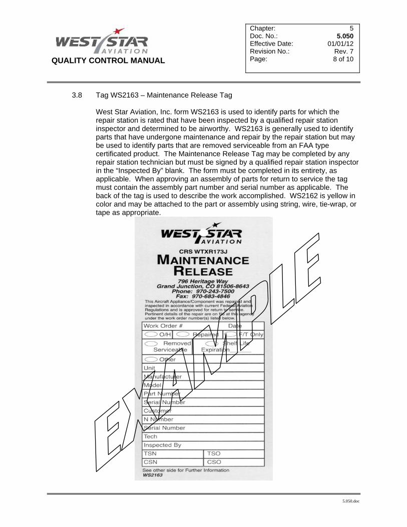
QUALITY CONTROL MANUAL
Chapter: Doc. No.: Effective Date: Revision No.: Page:
5 5.050
01/01/12 Rev. 7 8 of 10
5.050.doc
3.8 Tag WS2163 – Maintenance Release Tag West Star Aviation, Inc. form WS2163 is used to identify parts for which the repair station is rated that have been inspected by a qualified repair station inspector and determined to be airworthy. WS2163 is generally used to identify parts that have undergone maintenance and repair by the repair station but may be used to identify parts that are removed serviceable from an FAA type certificated product. The Maintenance Release Tag may be completed by any repair station technician but must be signed by a qualified repair station inspector in the “Inspected By” blank. The form must be completed in its entirety, as applicable. When approving an assembly of parts for return to service the tag must contain the assembly part number and serial number as applicable. The back of the tag is used to describe the work accomplished. WS2162 is yellow in color and may be attached to the part or assembly using string, wire, tie-wrap, or tape as appropriate.

QUALITY CONTROL MANUAL
Chapter: Doc. No.: Effective Date: Revision No.: Page:
5 5.050
01/01/12 Rev. 7 9 of 10
5.050.doc
3.9 Tag WS2164 – Identification Tag West Star Aviation, Inc. form WS2164 is used to identify parts that have been removed from an aircraft or engine currently in work, when the part is not in need of repair, and will be re-installed to the aircraft or engine upon completion of the current work scope. The Identification Tag may be completed by any repair station technician, and must contain Work Order Number and N Number at a minimum. It is acceptable to use one tag to identify a table or storage bin that will contain several parts removed from the aircraft or engine. WS2164 is gray in color and may be attached using string, wire, tie-wrap, tape, or clear identification tag pouches as appropriate.
4.1 Tag WS2167 – Warranty Core Tag

QUALITY CONTROL MANUAL
Chapter: Doc. No.: Effective Date: Revision No.: Page:
5 5.050
01/01/12 Rev. 7
10 of 10
5.050.doc
West Star Aviation, Inc. form WS2167 is used to identify parts that have been removed from an aircraft or engine currently in work, when the part is in need of repair and is to be returned to a supplier for warranty credit. The Warranty Core Tag may be completed by any repair station technician, and must contain at least the Work Order Number, Squawk Number, Part Name, Removed By, Date Removed, and Reason Removed. It is acceptable to use one tag for an assembly of parts when the assembly is to remain assembled. WS2167 is blue in color and may be attached to the part or assembly using string, wire, tie-wrap, or tape as appropriate.

QUALITY CONTROL MANUAL
Chapter: Doc. No.: Effective Date: Revision No.: Page:
5 5.060
06/01/10 Rev. 6 1 of 2
5.060
Title: REPAIR STATION STAMPS 1.0 Purpose:
1.1 This section describes the stamps used by the Repair Station. Many additional general use stamps (such as “Preliminary Draft”, “Copy”, etc.) may be employed in the Repair Station.
2.0 Responsibilities:
2.1 Technicians and inspectors, who use stamps described herein, shall be familiar with the requirements of this document.
3.0 Procedures:
3.1 The following table identifies each stamp by name, provides a sample, and describes the correct use. The format of these stamps may vary from stamp to stamp.
WORK ORDER STAMPS
NAME SAMPLE DESCRIPTION
FOR BILLING PURPOSES ONLY
For use on work orders used as an invoice only. May not be used on work orders, which document squawks, corrective actions, or inspections.
REPAIR STATION
This stamp is used to attach West Star’s Name and Repair Station Number to a document.
FOR INFO. PURPOSES ONLY…
For use on individual squawks that are informational only. These squawks are not airworthy and do not require inspection sign off.
4.0 STAMPS USED ON OTHER DOCUMENTS
4.1 The following table identifies each stamp by name, provides a sample, and describes the correct use. The format of these stamps may vary from stamp to stamp.
NAME SAMPLE DESCRIPTION
WEIGHT AND BALANCE…
Used to indicate that the current weight and balance information has been superceded by re-weigh or by calculating a new weight and balance.
SIGNATURE This stamp provides the means to add a signature block to a document.
FOR BILLING ONLY NO SIGNATURE REQUIRED
WEST STAR AVIATION, Inc. CRS WTXR173J
WEIGHT AND BALANCE INFO SUPERSEDED DATE_________ WEST STAR AVIATION, CRS WTXR173J SIGNATURE________________________
SIGNATURE_____________________ WEST STAR AVIATION
Grand Junction, Colorado CRS No. WTXR173J
FOR INFORMATIONAL PURPOSES ONLY.
NOT A DISCREPANCY

QUALITY CONTROL MANUAL
Chapter: Doc. No.: Effective Date: Revision No.: Page:
5 5.060
06/01/10 Rev. 6 2 of 2
5.060
NAME SAMPLE DESCRIPTION
RECEIVING INSPECTION
This stamp is used to document that an authorized Repair Station inspector accomplished a Receiving Inspection on the parts, components, etc which are listed on the stamped document.
VENDOR
This stamp will be used on the first page of a vendor packet received from a prospective vendor. The accounting department will assign the Vendor Code. The Quality Assurance Manager or designee will assign the Receiving Action Code. The vendor will be Approved by the Quality Assurance Manager or designee and then dated.
COPY STAMP
This stamp will be placed on the first page of any document that is copied out of a controlled document. Upon completion of the workscope that the document was use for, the document must be placed in the work order or labeled for reference only or disposed of.
QUALITY ASSURANCE INSPECTOR STAMP
This stamp will only be used by qualified QA inspectors after inspection and final review of items found in work orders, receiving inspections etc. This stamp will be in blue ink. Inspector initials may be used in stead of this stamp if the stamp comes unavailable. If the stamp is lost or stolen, it must be reported to the QA Manager as soon as possible.
These materials have been inspected and Found to conform with the requirements of 14CFR §145.211 Receiving Inspector___________________ West Star Aviation, Inc. CRS WTXR173J Date________________________________
Vendor Code___________________ Approval Status Code___________ Function Code_________________ Reviewed by___________________ Date__________________________ West Star Aviation
CRS WTXR173J
COPY VALID FOR USE WITH: WORK ORDER____________ DATED: __________________
WSA Employee #
QA

Quality Control Manual
Chapter: Doc. No.: Effective Date: Revision No.: Page:
5 5.070
01/01/12 Rev. 7 1 of 1
5.070.doc
Title: Repair or Modification Approval Form (WSF .802)

QUALITY CONTROL MANUAL
Chapter: Doc. No.: Effective Date: Revision No.: Page:
5 5.071
07/01/07 Rev. 3 1 of 1
5.071
Title: Repair or Modification Form (WSF .802) Instructions
1.0 Each item number corresponds to a number located in one of the blanks on the sample .802 form, located on Doc. # 5.070 of the QCM manual. All blanks must me completed on the form. If not applicable, write in “N/A”.
NOTE: The small letters in the individual boxes indicate which department is responsible. P: Production QA: Quality Assurance E: Engineering
1 Production personnel will enter the aircraft registration number
2 Production personnel will enter the aircraft Make
3 Production personnel will enter the aircraft Model
4 Production personnel will enter the aircraft Serial Number
5 Production personnel will enter the Work Order number assigned to the aircraft
6 Production personnel will enter the squawk number relating to the Repair or Modification. Multiple squawks are allowed on one .802 form, provided they are distinctly documented.
7 Production personnel will enter reference data proposed for the Repair or Alteration with assistance from QA or engineering if required
8 Production personnel will Sketch/Describe the repair or alteration in detail to include were applicable: Location using stations, weight, materials, hardware/fasteners and serialized articles being removed.
9 Production personnel will print the name of individual which is submitting the form
10 Quality Assurance personnel will enter the initial of QA Inspector approving the repair or modification
11 Quality Assurance personnel will enter the date of the QA Inspector approval
12 Engineering personnel will enter the initial of engineer approving the repair or modification. Engineering approval may not always be necessary if the QA department has determined that sufficient approved data is available. If this is the case “N/A” will be placed in this block.
13 Engineering personnel will enter the date of engineering approval
14 Quality Assurance Manager/Accountability Manager, Quality Assurance Team Leader or Quality Assurance Inspector will determine if the repair or alteration is Major or Minor and put a check were applicable.
15 Quality Assurance with Engineering assistance if required, will make the determination of what type of paper work will be used to return to service the repair or alteration and put a check were applicable.

QUALITY CONTROL MANUAL
Chapter: Doc. No.: Effective Date: Revision No.: Page:
5 5.080
07/01/07 Rev. 3 1 of 1
5.080.doc
Title: Disposition of Quarantined Parts Form (WSF.041)

QUALITY CONTROL MANUAL
Chapter: Doc. No.: Effective Date: Revision No.: Page:
5 5.090
03/01/14 Rev. 9 1 of 3
5.090 Rev. 9.doc
Title: Contract Maintenance Providers Audit Form, pg. 1 (WSF014A)

QUALITY CONTROL MANUAL
Chapter: Doc. No.: Effective Date: Revision No.: Page:
5 5.090
03/01/14 Rev. 9 2 of 3
5.090 Rev. 9.doc
Title: Contract Maintenance Providers Audit Form, pg. 2 (WSF014A)

QUALITY CONTROL MANUAL
Chapter: Doc. No.: Effective Date: Revision No.: Page:
5 5.090
03/01/14 Rev. 9 3 of 3
5.090 Rev. 9.doc
Title: Contract Maintenance Providers Audit Form, pg. 3 (WSF014A)

QUALITY CONTROL MANUAL
Chapter: Doc. No.: Effective Date: Revision No.: Page:
5 5.100
06/01/10 Rev. 6 1 of 1
5.100.doc
Title: Online-Service Difficulty / M or D Entry Form (http://av-info.faa.gov/isdr/default.asp) NOTE: Instructions for use of this form is self explanatory on the Web site

QUALITY CONTROL MANUAL
Chapter: Doc. No.: Effective Date: Revision No.: Page:
5 5.110
07/01/07 Rev. 3 1 of 1
5.110
PAGE NOT USED

QUALITY CONTROL MANUAL
Chapter: Doc. No.: Effective Date: Revision No.: Page:
5 5.111
07/01/08 Rev. 4 1 of 1
5.111.doc
Title: Inspection Authority Card Purpose: This card will be issued to inspectors employed by West Star Aviation once
a determination of qualifications have been made by the employees direct supervisor and the Quality Assurance Manager or designee. The inspector will carry this with him/her when away from base. The employee will return this card to the QA department if the inspection authorities are revoked or upon termination of employment.
(Name) REPAIR STATION INSPECTION AUTHORITY QA Inspector QC Inspector Category 1 or 2 PMA Inspector Return to Service After Hours/Away from Base
IA Limited to: Limitations and authority as outlined in the WSA Repair Station & Quality Control Manual QA APPROVAL: Inspector Signature:
By signing, Inspector acknowledges that Limitations and Authority are as outlined in the WSA Repair Station/Quality Control Manual and as granted by the Quality Assurance Manager. This Inspection Authorization is valid while your are employed by West Star, CRS# WTXR173J, unless sooner suspended or revoked by the Quality Assurance Manager. WSF 053A

QUALITY CONTROL MANUAL
Chapter: Doc. No.: Effective Date: Revision No.: Page:
5 5.112
07/01/07 Rev. 3 1 of 1
5.112.doc
Title: Suspected Unapproved Parts Notification, FAA form 8120-11

QUALITY CONTROL MANUAL
Chapter: Doc. No.: Effective Date: Revision No.: Page:
5 5.113
01/01/12 Rev. 7 1 of 1
5.113.doc
Title: Self-Evaluation Check list #14, Records of Overhaul and rebuilding (14CFR 43.2) This is an example of individual checklists used in the self-evaluation/audit
program that is specifically titled to ensure all aspects of applicable Federal Aviation Regulations are complied with on a daily basis.

QUALITY CONTROL MANUAL
Chapter: Doc. No.: Effective Date: Revision No.: Page:
5 5.114
01/01/12 Rev. 7 1 of 2
5.114.doc
Title: Non-Conformance Write-up and Corrective action form
In the event of non-conformities, the (Non-Conformance Write-up) will be used for recording non conformities, root cause and corrective actions.

QUALITY CONTROL MANUAL
Chapter: Doc. No.: Effective Date: Revision No.: Page:
5 5.114
01/01/12 Rev. 7 2 of 2
5.114.doc

QUALITY CONTROL MANUAL
Chapter: Doc. No.: Effective Date: Revision No.: Page:
5 5.115
01/01/12 Rev. 7 1 of 1
5.115.doc
Title: Certificate of Calibration ��A certificate of calibration shall be created for each tool calibrated by West Star
to include newly purchased tools.

QUALITY CONTROL MANUAL
Chapter: Doc. No.: Effective Date: Revision No.: Page:
5 5.116
01/01/12 Rev. 7 1 of 1
5.116.doc
Title: WSF125-Tools due for calibration ��This form is a computer generated form based on tools that are coming due for
calibration.

QUALITY CONTROL MANUAL
Chapter: Doc. No.: Effective Date: Revision No.: Page:
5 5.117
01/15/15 Rev. 10
1 of 5
5.117 Rev. 10.doc
Title: THE USE AND CONTROL OF WEST STAR AVIATION FORM WSF 043, 043A & 043B “EQUIPMENT REMOVAL & INSTALLATION LIST” (R & I sheets).
Purpose:
During the course of maintenance, the R & I sheet is to be used to supplement the work order to assist in the documentation of maintenance.
Responsibility:
All production personnel are required to use and control WSF 043 to document the removal and installation of parts and loose equipment to facilitate maintenance during the course of maintenance and inspections to support the work order.
Procedure: USE: The following is an example of items required to be documented on the WSF 043. This list is not
all inclusive. Additional items may be added as required by the work scope. -Engines -Seats -Engine serialized accessories -Sidewalls -Landing gear main and nose assemblies -Carpet -Landing gear serialized components -Seat Belts -Tire & Wheel Assemblies -Headliners -Serialized Avionics Components -Cabinetry -Flight controls -Bulkheads -Panels and fairings, either individually, -Any support equipment/tools used for or by use of a panel form. If panel forms are an aircraft system for the purpose used, the panel form must be referenced in the work order. of adjustment/test.
1. All items categorized as a Critical Inspection Item, or Required Inspection Item for Part 135 operators
and serialized components, must be documented in the Work Order and WSF 043 form as required. 2. An OEM inspection check list does not substitute WSA 043 for the removal and re-installation of
components and will not be used as such. 3. Any articles removed that are not categorized as a Critical Inspection/Required Inspection Item must
be documented on the WSF 043 form. If any of these items have R & R instructions they must be documented in the work order as well.
4. Panel sheets are allowed to be used to supplement the work order and WSF 043. Panel sheets must be controlled as a West Star Form (WSF), and referenced in the work order in the resolution of the applicable work scope.
5. Any aircraft system that is defeated. Example: Squat switches, must be documented on the R & I sheet.
6. Anything disassembled, disconnected, or disturbed but not removed from the aircraft. Example: Hinged panels, radomes, etc.
7. Any tool that is affixed to the aircraft. Example: Jack pads, Plugs or caps for the purpose of isolating pneumatic or hydraulic systems.
CONTROL: 1. The Airframe Team Lead will be responsible for the initial creation of the R & I book as indicated
below. 2. In the event Airframe does not have a work scope on the aircraft, it will be the responsibility of the
Team Leader whom has a work scope to create and maintain the R & I book. 3. There will be a “Red” R & I book maintained at each aircraft at all times. If the aircraft moves, the R &
I book goes with it. 4. The R & I book will contain a front cover sheet, WSF 043A form.

QUALITY CONTROL MANUAL
Chapter: Doc. No.: Effective Date: Revision No.: Page:
5 5.117
01/15/15 Rev. 10
2 of 5
5.117 Rev. 10.doc
5. The R & I book will have individual tabs labeled for each department. 6. The R & I book will have an index, WSF 043B inserted at the beginning of the book to assist in
managing the quantity of R & I sheets. 7. Upon the initial creation of the R & I book, one each “white” R & I sheet per department will be printed
and placed in the R & I book. After the R & I book is created. It will be the responsibility of the individual departments to maintain their section of the R & I book.
8. The WSF 043 & 043B form is considered part of the work order package and must be provided to the appropriate QA inspector upon completion of the work scope and prior to aircraft approval for return to service.
9. If a WSF 043 form is not used in its entirety, the remaining open line items must have a line drawn through them and the line titled, “N/A”. A single line through multiple items is allowed.
10. All “Initial” Blocks requiring an “Initial” will also require the technician to document their employee number below their initial(s). An “Initial” listing showing the name of the technician with their associated employee number can be located on the West Star Intranet under the “Quality” tab. This listing will be maintained by the QA department.

QUALITY CONTROL MANUAL
Chapter: Doc. No.: Effective Date: Revision No.: Page:
5 5.117
01/15/15 Rev. 10
3 of 5
5.117 Rev. 10.doc
11. Block by block instructions for WSF 043, “Equipment Removal & Installation List
BLOCK # DESCRITION AND INSTRUCTION
1 DEPARTMENT: Insert department responsible for the sheet 2 & 3 SHEET of : Insert sheet number and quantity of sheets to support the work scope
4 WORK ORDER: Insert Work Order number 5 REGISTRATION #: Insert Aircraft registration number 6 A/C MAKE: Insert A/C Make 7 A/C Model: Insert aircraft model 8 A/C S/N: Insert aircraft serial number 9 SQ #: Insert the squawk number of the item as indicated in the work order
10 ITEM DESCRIPTION: Insert a brief description of the item to be removed or installed
11 PART #: Insert the Part Number of the item if it is to be permanently removed. Part Number will also be inserted for items installed that are part of “new installation”.
12 FRAME STATION: Insert the Frame Station of the item only if the item is to be permanently removed. Frame Station will also be inserted for items installed that are part of “new installation”.
13 SERIAL #: Insert the Serial Number of the item only if the item is to be permanently removed. Serial Number will also be inserted for items installed that are part of “new installation”.
14 ITEM WEIGHT: Insert the Item Weight of the item only if the item is to be permanently removed. Item Weight will also be inserted for items installed that are part of “new installation”.
15 REMOVED BY INITIAL: Insert initials for the technician removing the item 16 REMOVED BY EMP. #: Insert employee number for the technician removing the item 17 REMOVED BY DATE: Insert the date the item was removed
18 OK to CLOSE INITIAL: Insert the initials for the authorized technician that has determined a particular area of the aircraft is OK to CLOSE.
19 OK to CLOSE EMP. #: Insert employee number for the authorized technician that has determined a particular area of the aircraft is OK to CLOSE.
20 INSTALLED BY INITIAL: Insert the initial for the technician installing the item 21 INSTALLED BY EMP #.: Insert the employee number for the technician installing the item. 22 INSTALLED DATE: Insert the date the item was installed
23 FT INITIAL: Insert the initials of the technician responsible for functionally testing the item after installation.
24 FT EMP. #: Insert the employee number of the technician responsible for functionally testing the item after installation.
25 FINAL INITIAL: Insert the initial of the technician responsible for the final inspection of the item installed.
26 FINAL EMP. #: Insert the employee number of the technician responsible for the final inspection of the item installed.
NOTE: Items that are permanently removed do not require a FINAL inspection.

QUALITY CONTROL MANUAL
Chapter: Doc. No.: Effective Date: Revision No.: Page:
5 5.117
01/15/15 Rev. 10
4 of 5
5.117 Rev. 10.doc
12. WSF 043A, Form is self explanatory. No Block by Block Instruction.
13. WSF 043B, Equipment Removal & Installation List Index Sheet:

QUALITY CONTROL MANUAL
Chapter: Doc. No.: Effective Date: Revision No.: Page:
5 5.117
01/15/15 Rev. 10
5 of 5
5.117 Rev. 10.doc
14. Block by block instruction for WSF 043B, Equipment Removal & Installation List Index Sheet:
BLOCK # DESCRITION AND INSTRUCTION
1 WORK ORDER: Insert Work Order number 2 REGISTRATION #: Insert Aircraft registration number 3 A/C MAKE: Insert A/C Make 4 A/C Model: Insert aircraft model 5 A/C S/N: Insert aircraft serial number 6 DATE: Insert the date the an R & I sheet is inserted in the R & I book under the
relevant department 7 INITIALS: Initials of the technician that inserted the R & I sheet into the R & I book
under the relevant department

QUALITY CONTROL MANUAL
Chapter: Doc. No.: Effective Date: Revision No.: Page:
5 5.118
03/01/14 Rev. 9 1 of 1
5.118 Rev. 9.doc
Title: WSF028-Aircraft Documentation Statement This form is to be provided to an owner/operator of an aircraft or component in the event the
owner/operator is unwilling or unable to provide the maintenance log books to allow West Star to conduct a research of all applicable Airworthiness Directives.

QUALITY CONTROL MANUAL
Chapter: Doc. No.: Effective Date: Revision No.: Page:
5 5.119
01/15/15 Rev. 10
1 of 2
5.119 Rev. 10.doc
Title: WSF1500 pg. 1- Away from Base Maintenance Release Form (Orange Tag) West Star Aviation, Inc. WSF 1500 page 1, is used to caution persons entering the
aircraft, for any purpose, that the aircraft is currently undergoing maintenance and is not safe for operation. One sheet is issued to the aircraft and placed on or in the aircraft by production prior to maintenance. The sheet needs to be placed so it is obvious to any person who might attempt to operate the aircraft. The WSF 1500 form is fluorescent orange in color to provide for quick detection. The aircraft may have multiple Work Orders opened against it. All departmental work orders will be listed on this sheet and will be cleared by Quality Control Inspector for the Operational Check Flight (OCF), if the OCF is required, by initialing in the Operational Check Flight box. The Sheet will remain in the aircraft during the OCF. Once the OCF is completed, any additional discrepancies will be cleared by the QC Inspector and then the Delivery box will be initialed by a QC Inspector.

QUALITY CONTROL MANUAL
Chapter: Doc. No.: Effective Date: Revision No.: Page:
5 5.119
01/15/15 Rev. 10
2 of 2
5.119 Rev. 10.doc
Title: WSF1500 pg. 2-Away from Base Maintenance Release Form (Orange Tag) West Star Aviation, Inc. WSF 1500 page 2, will be used in the performance of maintenance to comply with a Preliminary Inspection and a Post Maintenance Inspection during an Away from Base event. The form is generic in structure and content and will be used as required based on work scope. The overall use of this form is self explanatory.

QUALITY CONTROL MANUAL
Chapter: Doc. No.: Effective Date: Revision No.: Page:
5 5.120
01/15/15 Rev. 10
1 of 1
5.120 Rev. 10.doc
Title: WSF1501-Away from Base Check List The use of this form is self explanatory

QUALITY CONTROL MANUAL
Chapter: Doc. No.: Effective Date: Revision No.: Page:
6 6.000
03/01/14 Rev. 9 1 of 1
6.000, Rev. 9.doc
CHAPTER 6
Inspection of Non Destructive Inspection (NDI), Testing (NDT), and Evaluation
(NDE)

QUALITY CONTROL MANUAL
Chapter: Doc. No.: Effective Date: Revision No.: Page:
6 6.010
03/01/14 Rev. 9 1 of 1
6.010
Title: Nondestructive Inspection (NDI) Program
1.0 Purpose: 1.1 To define West Star Aviations Nondestructive Inspection (NDI) Program/Organization.
2.0 Responsibilities:
2.1 The Quality Assurance Manager is responsible for West Star Aviation, Inc.’s Nondestructive Inspection (NDI), Testing (NDT) and Evaluation (NDE) program. The responsibility includes program development, for the control and administration procedures on all nondestructive specifications listed on West Star Aviation, Inc.’s Operation Specifications and those incorporated into a rated article’s normal CMM inspection procedures by the OEM or through ICAs. The NDT Lead Technician is designated as the back-up position.
3.0 Procedure:
3.1 Any Nondestructive Inspection (NDI), Testing (NDT) and Evaluation (NDE) maintenance function selected for being accomplished by contract maintenance providers will be managed and approved in advance by the FAA IAW the West Star Repair Station Manual Doc. No. 6.000, Contract Maintenance.
3.2 Nondestructive Inspection (NDI) and Testing (NDT) and Evaluation (NDE) program’s process, which are selected for in-house accomplishment at West Star Aviation, Inc. will:
Use the guidelines of AC 65-31 as revised.
Use the standards for qualification, certification, and training of NDI personnel will meet the criteria of ASNT-TC-1A, NAS-410 & ASTM E-1444 as revised.
West Star Aviation NDT manual as revised.
Nondestructive Inspection (NDI) and Testing (NDT) and Evaluation (NDE) processes that are selected for in-house accomplishment at West Star Aviation, Inc. are:
Magnet Particle (MP) Liquid Penetrant (LP) Eddy Current (EC) Ultrasound (US) Radiographic
3.3 Nondestructive Inspection (NDI) and Testing (NDT) and Evaluation (NDE) processes that are selected for in-house accomplishment at West Star Aviation, Inc. will have established a written program for the control and administration of personnel training, examination, qualification and documentation that satisfy the processes’ requirements. These processes are documented in West Star Aviation, Inc.’s NDT Manual.
3.4 The program will also include a method for maintaining proficiency, including recurrent training and steps to decertify, retrain or recertify as required.
3.5 The program will be maintained current and be made available for review upon request during normal business hours.

Rev. 7 EASA SUPPLEMENT TO THE 14 CFR Part 145 Page 1 of 40 WEST STAR REPAIR STATION MANUAL MAR/07/2014
West Star Aviation, Inc 796 Heritage Way
Grand Junction, CO 81506
West Star Aviation Additional Fixed Location 12 West Airport Road
Aspen-Pitkin County Airport Aspen, CO 81611
EASA APPROVAL CERTIFICATE
NUMBER: 145.5010
FAA REPAIR STATION CERTIFICATE NUMBER: WTXR173J
Reference: West Star Aviation (RSM/QCM), Repair Station & Quality Control Manual as
revised.
MANUAL CONTROL NUMBER: _________
This Supplement does not form part of the FAA 14 CFR part 145 RSM/QCM. Compliance with the FAA accepted Supplement together with the FAA CFR part 145 RSM/QCM forms the basis of the European Aviation Safety Agency (EASA) Part-145 approval. The States of the EASA Full Member Authorities are; Austria, Belgium, Bulgaria, Cyprus, Czech Republic, Denmark, Estonia, Finland, France, Germany, Greece, Hungary, Iceland, Ireland, Italy, Latvia, Liechtenstein, Lithuania, Luxembourg, Malta, Norway, Poland, Portugal, Romania, Slovak Republic, Slovenia, Spain, Sweden, Switzerland, The Netherlands and United Kingdom. This supplement forms part of West Star Aviations obligations for EASA Part-145 approval as specified in the MAG. This supplement was developed using EASA Maintenance Annex Guidance (MAG) Change 4, effective date JAN/29/2014 . Superseding former Maintenance Implementation Procedures Guidance (MIP-G).

Rev. 7 EASA SUPPLEMENT TO THE 14 CFR Part 145 Page 2 of 40 WEST STAR REPAIR STATION MANUAL MAR/07/2014
TABLE OF CONTENTS Paragraph/Section Page No.
COVER SHEET ............................................................................................................... 1
TABLE OF CONTENTS .................................................................................................. 2 SECTION 1: LIST OF EFFECTIVE PAGES ................................................................... 3
SECTION 2: AMENDMENT PROCEDURE .................................................................... 4
SECTION 3: INTRODUCTION ........................................................................................ 4
SECTION 4: ACCOUNTABLE MANAGER'S COMMITMENT STATEMENT ................. 5
SECTION 5: APPROVAL BASIS AND LIMITATION ..................................................... 5
SECTION 6: ACCESS BY THE EASA AND FAA .......................................................... 5
SECTION 7: WORK ORDERS/CONTRACTS ............................................................. 5-6
SECTION 8: APPROVED DESIGN REPAIR DATA .................................................... 6-7
SECTION 9: AIRWORTHINESS DIRECTIVES ............................................................... 7
SECTION 10: MAJOR REPAIRS, ALTERATIONS, AND MODIFICATIONS ................. 7
SECTION 11: RELEASE OF COMPONENTS AFTER MAINTENANCE ..................... 8-9
SECTION 12: CERTIFICATE OF AIRWORTHINESS (C of A) VALIDITY ..................... 9
SECTION 13: RELEASE OF AIRCRAFT AFTER MAINTENANCE ............................... 9
SECTION 14: REPORTING OF UNAIRWORTHY CONDITION ................................... 10
SECTION 15: QUALITY ASSURANCE SYSTEM ................................................... 11-13
SECTION 16: PROVISION OF HANGAR SPACE FOR AIRCRAFT MAINTENANCE 13
SECTION 17: CONTRACTED MAINTENANCE ........................................................... 14
SECTION 18: HUMAN FACTORS ................................................................................ 14
SECTION 19: LINE STATIONS .................................................................................... 14
SECTION 20: WORK AWAY FROM A FIXED LOCATION ..................................... 14-15
APPENDIX 1 – QUALITY SYSTEM AUDIT FORMS ............................................... 16-32
APPENDIX 2 - FAA FORM 8130-3 EXAMPLE & INSTRUCTIONS ........................ 33-36
APPENDIX 3 - EASA REQUIREMENTS CHECKLIST ............................................ 37-38
APPENDIX 4 - GLOSSARY OF ABBREVIATIONS ................................................ 39-40

Rev. 7 EASA SUPPLEMENT TO THE 14 CFR Part 145 Page 3 of 40 WEST STAR REPAIR STATION MANUAL MAR/07/2014
Section 1. LIST OF EFFECTIVE PAGES
Page Date Revision Page Date Revision
1 MAR/07/2014 7 21 AUG/01/2011 6
2 MAR/07/2014 7 22 MAR/07/2014 7
3 MAR/07/2014 7 23 MAR/07/2014 7
4 AUG/01/2011 6 24 MAR/07/2014 7
5 MAR/07/2014 7 25 MAR/07/2014 7
6 MAR/07/2014 7 26 MAR/07/2014 7
7 MAR/07/2014 7 27 MAR/07/2014 7
8 MAR/07/2014 7 28 MAR/07/2014 7
9 MAR/07/2014 7 29 MAR/07/2014 7
10 AUG/01/2011 6 30 MAR/07/2014 7
11 MAR/07/2014 7 31 MAR/07/2014 7
12 MAR/07/2014 7 32 MAR/07/2014 7
13 MAR/07/2014 7 33 MAR/07/2014 7
14 MAR/07/2014 7 34 MAR/07/2014 7
15 MAR/07/2014 7 35 MAR/07/2014 7
16 AUG/01/2011 6 36 AUG/01/2011 6
17 AUG/01/2011 6 37 AUG/01/2011 6
18 AUG/01/2011 6 38 AUG/01/2011 6
19 AUG/01/2011 6 39 AUG/01/2011 6
20 AUG/01/2011 6 40 AUG/01/2011 6
Note: Appendix 1, 2, 3 & 4 contain separate reference documents, which are not included in
this list of effective pages. Approved by: _____________________________ __________________ West Star Accountable Manager Date Acceptance of: _____________________________ __________________ FAA Flight Standards District Office Date

Rev. 7 EASA SUPPLEMENT TO THE 14 CFR Part 145 Page 4 of 40 WEST STAR REPAIR STATION MANUAL MAR/07/2014
Section 2 AMENDMENT PROCEDURE This Supplement shall be revised as required consistent with current operations and EASA requirements. The Quality Assurance Manager will review this Supplement periodically; confirming the EASA Supplement is still current and valid for use, or identifies needed changes. The Quality Assurance Manager will have any revisions he finds necessary produced in a final form and approved by the Accountability Manager for coordination with the FAA Flight Standards District Offices (“FAA FSDO”) at Salt Lake City, Utah as described below. Each revision to this Supplement will include all pages, which will all bear the new revision number and date. The Quality Assurance Manager will send two copies of each revision to the Flight Standards District Office for review. Upon acceptance of the proposed revision, the FAA Flight Standards District Office will sign and date the appropriate line on the List of Effective Pages. One copy is then returned to West Star and the other retained to revise the Flight Standards District Office's copy of the Supplement. Receipt of the returned copy from the FAA FSDO by the repair station signifies revision of the Flight Standards District Office's copy of the Supplement. Upon receipt of the FAA accepted revision at West Star, the Quality Assurance Manager will distribute copies of the revision and attach a copy of West Star form # WSF.027, to each copy. These copies will be distributed to all manual holders. Each supplement will have a control number and an assignment entry on the supplement cover page. A master list containing the supplement number, location and revision status will be kept in the Inspection Office. With the assistance of West Star’s computer department, an electronic version of the supplement will be maintained and revised on the company Intranet of which all technicians have access. Upon receipt of the revision, each supplement holder is responsible for reviewing and inserting the revised Supplement into his/her assigned Repair Station Manual. Once revised, the manual holder must sign and date the Form WSF.027 and return it to the Quality Assurance Manager. The Form WSF.027 is used to certify that the revision has been reviewed and is understood by the manual holder and that the Supplement has been inserted into the manual. Returned Form WSF.027 are kept on file in the Quality Assurance Manager office and serve as a means of assuring Repair Station Manual Revision Status Control. Additions, deletions, or revisions to text in an existing section will be identified by a revision bar in the margin of the page adjacent to the change, by highlighting the text in red, or both. Section 3 INTRODUCTION This Supplement to the West Star Repair Station Manual is required for continued EASA Part 145 approval of maintenance work on all aircraft and components operated under the authority of the members of the EASA. The EASA has agreed that the FAA is a recognized authority by means of a Bilateral Aviation Safety Agreement. The EASA has specified the basic difference between EASA Part 145 and CFR Part 145 to ensure equivalence with EASA Part 145. These differences are outlined in the Maintenance Annex Guidance (MAG), agreed between the EASA and FAA and identifies these differences as Special Conditions. Consequently, a CFR Part 145 Repair Station can be EASA Part-145 approved, when the Repair Station complies with the maintenance Special Conditions as detailed in this supplement in addition to complying with 14 CFR parts 145 & 43. This Supplement therefore reminds West Star that it is performing maintenance in accordance with the EASA Part 145 Approval Certificate and identifies the differences from the FAR’s that need to be taken into account.

Rev. 7 EASA SUPPLEMENT TO THE 14 CFR Part 145 Page 5 of 40 WEST STAR REPAIR STATION MANUAL MAR/07/2014
Section 4 ACCOUNTABLE MANAGER'S COMMITMENT STATEMENT
This EASA Supplement, in conjunction with West Star accepted 14 CFR part 145 RSM/QCM, defines the organization, policy, and procedures upon which EASA approval is based. These procedures are approved by the undersigned, and must be adhered to, as applicable, when maintenance work/orders are being accomplished under the conditions of EASA Part-145. The West Star Aviation, Inc. procedures do not override the necessity of complying with any additional requirements formally published by the EASA and forwarded to West Star. It is understood that EASA Shall issue an Approval Certificate and list the repair station in an EASA list as long as the EASA is satisfied that the procedures are being followed and work standards maintained. It is further understood that the EASA reserves the right to revoke the Approval Certificate if EASA considers that procedures are not followed or standards not upheld. Signature:________________________________Date:__MAR/07/2014__ Kevin T. Bostwick Accountable Manager
Section 5 APPROVAL BASIS AND LIMITATION
EASA approval of maintenance is limited to the scope of work permitted under the current approval granted by the FAA to West Star, under West Star Aviation Air Agency Certificate and Operation Specifications, and in accordance with CFR Part 145 except when varied by the Special Conditions specified in the MAG, and associated guidance carried out in locations within the United States unless agreed otherwise on a case-by-case basis by the Agency. EASA approval is based on West Star compliance with CFR Parts 43 and 145. However, this approval must not exceed the ratings permitted by Commission Regulation (EC) No. 2042/2003.
Section 6 ACCESS BY THE EASA AND FAA
The FAA and EASA or EASA-member EASA staff shall be allowed access to West Star facilities and documents to verify initial and continued compliance with 14 CFR Parts 43 and 145, and the Special Conditions. Furthermore, the FAA staff shall be allowed access to ascertain compliance and investigate problems on behalf of the EASA. West Star will accept and cooperate with any investigation and enforcement action that may be taken by EASA in accordance with any relevant EU regulations and EASA procedures.
Section 7 WORK ORDERS/CONTRACTS
Maintenance performed by West Star for foreign operators is complicated by the fact that there may be occasions when non-FAA maintenance requirements, such as a foreign Airworthiness Directive are not known to West Star. This may occur because the information is not included in the information routinely reviewed by West Star. Consequently, the customer is responsible to provide explicit instructions for all work subject to the procedures and requirements of this Supplement.

Rev. 7 EASA SUPPLEMENT TO THE 14 CFR Part 145 Page 6 of 40 WEST STAR REPAIR STATION MANUAL MAR/07/2014
Section 7 WORK ORDERS/CONTRACTS (continued) If there are any questions about the interpretation of a work order or other work instructions, clarification shall be obtained from the customer before work begins. In general, work orders should specify the inspections, repairs, alterations, overhaul, airworthiness directives, and parts replacements that must be carried out. The Team Leader assigned to the project shall be the primary customer contact and shall assure that all customer instructions are understood and carried out completely, including EASA AD’s and other mandatory instructions. Section 8 APPROVED DESIGN AND REPAIR DATA
a) Changes to the type design: Major Changes, Minor Changes, STC’s. (1) The EASA-approved design engineering data is normally data supplied by an EASA Design Organization Approval (DOA) holder, or data approved by the National Aviation Authority of the Type Certificate Holder (or equivalent), or data supplied by the customer and approved by the EASA. In all cases, the customer is responsible for confirmation of data approval. Details for the acceptance and /or validation of FAA approved changes to the type design by EASA are contained in Annex 1 to the Agreement and in the Technical Implementation Procedures (TIP). NOTE: EASA defines “design change” as a change to the type design. EASA does not
automatically accept alterations that affect type design.
b) Repairs.
(1) FAA shall approve design data in support of major repairs in accordance with FAA Order 8110.4, Type Certification; FAA Order 8110.37, Designated Engineering Representative Guidance Handbook; FAA Order 8100.15, Organization Designation Authorization Procedures; and FAA Order 8900.1, Flight Standards Information Management System. Minor repairs are made in accordance with “acceptable” data, in accordance with 14 CFR Part 43.
(2) EASA shall approve design data in support of repairs in accordance with EASA Part 21 Subpart M Repairs and EASA’s procedure Type Certificate Change and Repair Approval.
c) EASA Acceptance of FAA Repair Design Data. Non-Critical Components.
(1) EASA shall accept data used in support of major repairs regardless of the State of Design of the product, part or appliance, if:
(i) EASA has certificated/validated the product or appliance, (ii) The FAA is the authority of the State of Design for the repair design data, and (iii) The FAA repair design data approval is substantiated via an FAA letter or FAA Form 8110-3, FAA Form 8100-9, properly executed FAA Form 337, or a signed cover page of a repair specification.
(2) EASA shall also accept data used in support of minor repairs when: (i) EASA has certificated/validated the product or appliance, (ii) The FAA is the authority of the State of Design for the repair design data, and (iii) The repair design data has been provided by a U.S. TC/STC or TSOA holder, or (iv) For minor repairs from other than a U.S. TC/STC or TSOA holder, the determination that data are acceptable (under 14 CFR Part 43) has been made by a U.S. maintenance organization under FAA’s authorized system,
NOTE: An EU company must use EASA Part 21 for the approval of repair data for use on an
EU-registered aircraft. Unless the minor repair data has been previously used on an

Rev. 7 EASA SUPPLEMENT TO THE 14 CFR Part 145 Page 7 of 40 WEST STAR REPAIR STATION MANUAL MAR/07/2014
N-registered aircraft, an EU company cannot determine any data to be acceptable data under 14 CFR Part 43 for use on an EU-registered aircraft.
Section 8 APPROVED DESIGN AND REPAIR DATA (cont.) (3) In these circumstances, repair design data are considered to be EASA approved following its approval or acceptance under FAA’s system. This process does not require application to EASA or compliance findings to the EASA certification basis.
Critical Components
NOTE: A critical component is defined as a part identified as critical by the design
approval holder during the validation process, or otherwise by the exporting authority. Typically, such components include parts for which a replacement time, inspection interval, or related procedure is specified in the Airworthiness Limitations section or certification maintenance requirements of the manufacturer’s maintenance manual or Instructions for Continued Airworthiness.
(4) EASA shall accept any critical component repair design data from a TC/STC holder, regardless of the State of Design of the product, if.
(i) EASA has certificated/validated the product, and (ii) The FAA is the authority of the State of Design for the repair design data. (iii) In these circumstances, repair design data are considered to be EASA approved following its approval under FAA’s system. This process does not require application to EASA or compliance findings to the EASA certification basis.
(5) Repair design data on critical components, developed by organizations/persons that are not the TC/STC Holder, shall be submitted to the Agency for approval following the standard application procedure, with an EASA Form 31. Applicants do not need to hold a DOA if the repair data has been approved by the FAA.
Section 9 AIRWORTHINESS DIRECTIVES
A number of EASA member authorities either issue their own airworthiness directives or accept FAA directives and issue additional directives. In either case West Star Aviation will access the applicable EASA AD’s via the aviation authority web site. All AD’s will be provided to production by the QA department via the web site or paper copy. West Star shall determine from the customer what airworthiness directives the customer requires to be followed in the work to be performed, and must hold a copy of those Airworthiness Directives. This information, if applicable, should be a part of the work order or other instructions. In some cases, it will be necessary for the customer to supply the information necessary to incorporate airworthiness directive requirements. In the event an AD is not complied with, the non-compliance will be recorded in the maintenance records and the owner/operator will be notified of this immediately via email, fax or personally by phone.
Section 10 MAJOR REPAIRS, ALTERATIONS, AND MODIFICATIONS
The approval of major repairs, alterations, and modifications usually involves EASA member authorities. Therefore, it is essential for the customer to ensure that the appropriate EASA national aviation authority has provided any required approvals, and that any repair station FAA approved data is acceptable. West Star shall establish that the customer has obtained the necessary approvals or has initiated action to do so before West Star begins any work.

Rev. 7 EASA SUPPLEMENT TO THE 14 CFR Part 145 Page 8 of 40 WEST STAR REPAIR STATION MANUAL MAR/07/2014
Section 11 RELEASE OF COMPONENTS AFTER MAINTENANCE
Release to service of components up to and including complete power plants shall be in accordance with FAR Part 43.9 and the additional requirements of Paragraphs 7 through 10 of this Supplement. At the completion of maintenance, West Star will issue an FAA Form No. 8130-3 as a maintenance release. Reference Appendix 2 of this supplement or FAA Order 8130.21, as revised, for detailed instructions for completing FAA Form 8130-3. In addition, Block 13 of the FAA Form 8130-3 must contain the following information: - West Star EASA Approval Certificate - Specify any overhaul; repairs, alterations, or AD’s accomplished - Specify any replacement or PMA parts used - Reference any approved data used to accomplish the work including issue/revision - and the following statement: “West Star” certifies that the work specified in block 12/13 was carried out in
accordance with EASA Part-145 and in respect to that work the component is considered ready for release to service under EASA Part-145 Approval Number: “EASA.145.5010“.
Blocks 14 through 18 are not to be used by West Star, and “newly overhauled” should be signed off in block 20 against the Block 19 maintenance release.
CAUTION The use of Parts Manufacturer Approval (PMA) parts on a component may not be approved by EASA-member NAA. If there are any questions concerning the approval status of parts or components to be used by West Star the customer shall provide clarification prior to the initiation of the work requiring such parts or components. West Star will indicate in their personal roster that have signature authority for FAA form 8130-3 on behalf of the repair station. Reference Appendix 2 in this supplement for detailed instructions for filling out FAA form 8130-3 to include an example form. Components authorized for use during maintenance should meet the intent of the following: 1. Component means any component part of an aircraft up to and including a complete power plant
and any operational or emergency equipment. 2. Only the following new and used components may be fitted during maintenance.
a) New Components 1. New components should be traceable to the OEM as specified in the Type Certificate (TC)
holders Parts Catalogue and be in a satisfactory condition for fitment. A release document issued by the OEM or Production Certificate (PC) holder should accompany the new component. The release documents should clearly state that it is issued under the approval of the relevant AA under whose regulatory control the OEM or PC holder works.
2. For USA OEM’s and PC holder’s release should be on the FAA Form 8130-3 as a new part. 3. For all EU States OEM’s and PC holder’s release should be in accordance with EASA Part
21. 4. For Canadian OEM’s and PC holder’s release should be on the Canadian; Form One as a

Rev. 7 EASA SUPPLEMENT TO THE 14 CFR Part 145 Page 9 of 40 WEST STAR REPAIR STATION MANUAL MAR/07/2014
new part. 5. Standard parts are exempt from the forgoing provisions, except that a conformity statement
should accompany such parts and be in a satisfactory condition for fitment. NOTE: EASA Standard Parts Definition: Per AMC M.A.501(c), “Standard Parts are: parts manufactured in complete compliance with an established industry, Agency, competent authority or other Government specification which includes design, manufacturing, test and acceptance criteria, and uniform identification requirements. The specification should include all information necessary to produce and verify conformity of the part. It should be published so that any party may manufacture the part. Examples of specifications are National Aerospace Standards (NAS), Army-Navy Aeronautical Standard (AN), Society of Automotive Engineers (SAE), SAE Sematec, Joint Electron Device Engineering Council, Joint Electron Tube Engineering Council, and American National Standards Institute (ANSI), EN Specifications etc…”
6. PMA parts may only be accepted as detailed in EASA Part 21 or in Annex 1 of the MAG. 7. Engines rebuilt by the production approval holder can be accepted as specified in the
Technical Implementation Procedures for Airworthiness and Environmental Certification (TIP-para. 5.1.4).
b) Used components
1. Used components shall be traceable to maintenance organizations and repair stations approved by the authority who certified the previous maintenance and/or in the case of life limited parts certified the life used. The used component must be in a satisfactory condition for fitment and be eligible for fitment as stated in the TC holder’s parts catalogue.
2. Used components from EASA approved USA repair stations should be accompanied by a FAA form 8130-3 issued as a maintenance release.
3. Used components from an USA repair station not EASA approved should not be used even if accompanied by a FAA form 8130-3.
4. Used components from EASA Part 145 approved maintenance organizations should be accompanied by an EASA from 1 issued as a maintenance release.
5. A Canadian; Form One issued as a maintenance release should accompany used components from a Canadian EASA-approved maintenance organization. NOTE: Canadian EASA-approved maintenance organizations will specify the EASA release statement and their EASA approval number in the remarks block of Canadian Form One.
Section 12 CERTIFICATE OF AIRWORTHINES (C of A) VALIDITY
Note: This paragraph is applicable only to FAR Part 145 repair stations with an aircraft rating. While EU aircraft have indefinite C of A’s the C of A’s validity period is verified by means of an “airworthiness review certificate” (ARC). The EASA operator or owner is responsible for ensuring the C of A remains valid; however, West Star will ensure that the C of A is valid from the expiration date as detailed on the ARC before issue of a release to service as specified in paragraph 13 off this Supplement. West Star will inform the customer if the ARC has expired. If a valid certificate is not available at the time of the release, the release will include a reference to the invalid certificate.

Rev. 7 EASA SUPPLEMENT TO THE 14 CFR Part 145 Page 10 of 40 WEST STAR REPAIR STATION MANUAL MAR/07/2014
Section 13 RELEASE OF AIRCRAFT AFTER MAINTENANCE
For all work accomplished under this Supplement, the release to service shall be accomplished in a manner consistent with 14 CFR Part 43.9 and Sections 7 through 10 and Section 12 of this Supplement. At the completion of maintenance, the following certification shall be made in the aircraft maintenance record. "I certify that the work specified, except as otherwise specified, was carried out in accordance
with FAA airworthiness regulations and with respect to that work the aircraft is considered ready for release to service."
The addition of the phrase "except as otherwise specified" shall be included whenever either or both of the following circumstances exists: 1. Not all maintenance was accomplished. In that case, the maintenance not accomplished
must be listed on the FAR 43.9 release. 2. The required maintenance was only EASA approved and not FAA approved, for example, an
EASA airworthiness directive not approved by the FAA. If the customer requires that the maintenance records indicate a release to service in accordance with EASA Part 145.A.50, the following alternate certification shall be made: Note: This paragraph is applicable only to FAR Part 145 repair stations with an aircraft rating. “West Star certifies that the work specified except as otherwise specified was carried out in
accordance with EASA Part 145 and in respect to that work the aircraft is considered ready for release to service”
In both cases, West Star shall issue the certification when all required maintenance has been completed. Both the EASA acceptance certificate number and the FAA 145 acceptance certificate number will be included in all maintenance entries. If it is not possible to complete all requirement maintenance, information on the incomplete maintenance or remaining airworthiness discrepancies shall be included in the maintenance record and the operator shall be so informed.
Section 14. REPORTING OF UNAIRWORTHY CONDITION
When serious defects are found in EASA regulated aircraft or components, such facts shall be reported to EASA the aircraft/component design organization, and the customer/operator or Operator within 72 hours of discovery. West Star will submit EASA Form 44, Occurrence Reporting Form or FAA form 8010-4 Malfunction Defect Report an/or FAA SUP as dialed in AC 21-29 or in a form and manner acceptable to EASA containing the information required by Part 145 in English. West Star will submit this form in accordance with the timeframe specified in EASA Part-145, when reportable problems are found on an aircraft, power plant, propeller, or component thereof that is subject to the regulatory control of EASA. The Quality Assurance Manager or designee will be responsible for completing and submitting reports of un-airworthy conditions to EASA.

Rev. 7 EASA SUPPLEMENT TO THE 14 CFR Part 145 Page 11 of 40 WEST STAR REPAIR STATION MANUAL MAR/07/2014
Section 15 QUALITY ASSURANCE SYSTEM (QAS)
A quality assurance system does not address the same issues as quality control or inspection systems. Quality Assurance (QA) is an independent top-level review that includes monitoring of the inspection process. A QA system focuses on whether the stated procedures and standards are actually being followed and whether they are effective in meeting the overall goals for maintaining airworthy products. The quality assurance process examines a sample of products and that it remains in compliance with 14 CFR Part 43, Part 145 and the EASA Special Conditions, and processes to verify that the end products meet all requirements, i.e. that the overall system works. The two elements to the system are:
1. An independent audit system 2. A management/control and follow up system.
1. Independent Audit System A. West Star Aviation, Inc.’s will maintain a quality assurance system that is independent of
the maintenance repair process, including part, product and their release to service inspections.
B. It is acceptable to use personnel from one section/department to audit the work and products of another section/department in accordance with procedures of this audit program. Independence shall be established by ensuring that audits are not carried out by the personnel responsible for the function, procedure, or product being audited.
C. Overall responsibility for West Star Aviation, Inc.’s Quality Assurance System (QAS) is assigned to the Manager of Quality Assurance. The Quality Assurance Auditor reports directly to the Manager of Quality Assurance/Accountable Manager.
D. The individual selected for the Quality Assurance Auditor position should have a thorough knowledge of the company’s Quality Control System, its departmental relationships, and had previous Quality Control or Auditor experience.
E. The Quality Assurance Auditor is responsible for ensuring that the QA program is accomplished according to the objectives and guidance established by the Accountable Manager by: 1. The accomplishment of QA audits 2. Providing support to responsible technical managers for the development of
solutions to audit observations 3. Completion of QA audit reports
F. The Quality Assurance Auditor position is assigned to the Manager of Quality Assurance’s group and is responsible for:
1. Developing an annual Quality Assurance (QA) audit plan. 2. Scheduling the resources for and managing all audits. 3. Coordinating and assisting in the analysis of any adverse findings and the development of
solutions. 4. Developing a plan and schedule for the implementation of all long term solutions and
interim fixes required. 5. Developing and maintaining QA reports and records.
G. By the first day of December each year, an annual plan for QA audits to be conducted during
the following calendar year will be developed. The plan contains a brief description of each audit area, the resources that will be required, and a schedule for the completion of each audit. The audit plan will include the routine periodic audits of each audit area/subject and follow up audits of any area that previously required any corrective action. The basic goal of

Rev. 7 EASA SUPPLEMENT TO THE 14 CFR Part 145 Page 12 of 40 WEST STAR REPAIR STATION MANUAL MAR/07/2014
Section 15 QUALITY ASSURANCE SYSTEM (QAS) (cont.)
the QA program is to monitor compliance with 14 CFR Part 43, 145 and this EASA Supplement.
H. The annual QA audit program will be conducted using common and product specific check
lists designed to review a product type’s systems, procedures, manuals; interviews with personnel and observation of work in progress. Form EASAWSF .015.1, (EASA Independent Audit) will be used as a audit scheduling form, Form GJTWSF .015,(Non-Conformance Write-up) will be used for recording non conformities, root cause and corrective actions. Form EASAWSF .015.1, in the left column, indicates areas of the repair station that will be audited using specific checklist for that area. For Example, Form EASAGJT .015.15 will be used to ensure overhauls are being accomplished in accordance with 14 CFR 43.2.
NOTE: For forms referenced in para. H above, refer to Appendix 1 for form examples.
I. Procedural audits will monitor compliance with required aircraft/aircraft component
standards and adequacy of the maintenance procedures to ensure that such procedures invoke good maintenance practices and airworthy aircraft/aircraft components. . These Procedural audits will apply to the West Star Aviation Additional Fixed location, (Aspen) under the category of multiple facilities.
J. Product audits will be accomplished via sampling checks to witness any relevant testing and visually inspect the product and associated documentation. The sample check will not involve repeat disassembly or testing unless the sample check identifies findings requiring such action. These Product audits will apply to the West Star Aviation Additional Fixed location, (Aspen) under the category of multiple facilities.
K. Audits of contractors will be accomplished in the same manner as indicated within
the West Star Aviation Repair Station Manual Doc. No. 6.020. L. Sample Audits will be conducted by Wes Star once per year as a single exercise or
conducted in segments during a period of one year in accordance with the audit program contained in this Supplement. All applicable 14 CFR parts 43 and 145 provisions and the EASA Special Conditions as detailed will be checked at least once per year against each primary product line.
M. Additional Fixed location at West Star’s Aspen, CO facility will be subjected to the
same audits, as required as indicated in this supplement.
2. Management/Control and follow up System
A. Any unexplainable observations found during the non-conforming audit will be documented on a “Non-Conformance Write up, Quality Systems Audit Form” GJTWSF .015, then forwarded to Manager of Quality Assurance/Accountable Manager and the responsible manager of non-conforming technical area audited for resolution. All rectification actions will be documented on the Quality Systems Audit Form, attaching additional sheets as required to make a complete documentation package. Those observations that require long term solutions (i.e.; more than 30 days) developed by the

Rev. 7 EASA SUPPLEMENT TO THE 14 CFR Part 145 Page 13 of 40 WEST STAR REPAIR STATION MANUAL MAR/07/2014
Section 15 QUALITY ASSURANCE SYSTEM (QAS) (cont.)
responsible manager(s) and accepted by the Accountable Manager, will be documented by the QA function in a corrective action plan – complete with interim corrective actions, permanent fixes with timetable and milestones established for each action required.
B. The Manager of Quality Assurance/Accountable Manager will hold routine meetings to check
the progress on clearing outstanding findings/discrepancies. Meeting should be held at least once per year with the senior staff involved to review the overall performance.
C. The responsible Program manager(s) are responsible for coordinating the development and
implementation of corrective actions that are satisfactory to the QA auditor, whenever problems are identified through QA audits. Long term problem rectification, the solution implementation will be developed by the responsible technical area manager with the assistance of the audit team, within a period no greater than 30 days.
D. Corrective actions will be derived from an analysis of the problem’s extent and “root” cause to
be sure that all affected activities or parts are identified. Then and only then will any immediate action required be taken. Interim actions required will be determined before the implementation of a permanent solution is initiated. All long term, permanent solutions ( 30 days) will be accompanied with a plan and timetable and be approved by the Accountable Manager before rectification is initiated.
E. The implementation of corrective actions will be monitored by the Quality Assurance Auditor
through status reports to the Manager of Quality Assurance/Accountable Manager. The status report may be in the form of inter-office memo (e-mail) or in direct meeting with the Accountable Manager or designee and Manager of Quality Assurance as required. Corrective action implementation and/or rectification will be verified through the use of special follow-up audits.
F. The Accountable Manager will be responsible for ensuring that:
1. The objectives of the annual audit plan are met. 2. The results of all audits are actioned by responsible technical managers in a timely
manner after they are properly documented. 3. All problems are appropriately addressed.
G. The Quality Assurance Auditor will develop and maintain a system of records to document the
QM program, the results of audits, the corrective actions taken to respond to problems and other records required to properly manage the QM program.
H. These records are confidential internal documents that are the property of West Star Aviation, Inc. Records of audits, corrective actions and results will be made available for FAA and/or EASA review at West Star Aviation, Inc.’s business address during normal working hours of the QA function. These records will be kept for 2 years.
Section 16 PROVISION OF HANGAR SPACE FOR AIRCRAFT MAINTENANCE
Covered Hangar space will be available for aircraft operated under the regulatory control of an EU member state, undergoing maintenance and alteration. Provisions for sufficient covered hangar space shall be made when the contract is signed.

Rev. 7 EASA SUPPLEMENT TO THE 14 CFR Part 145 Page 14 of 40 WEST STAR REPAIR STATION MANUAL MAR/07/2014
Section 17 CONTRACTED MAINTENANCE
A. If West Star contracts part of the maintenance of EASA controlled EU registered aircraft or components for installation on those aircraft, to another organization, it will ensure that the other organization is either listed by the EASA for the maintenance that they perform, or such contracted organizations must work under the West Star Repair Station in accordance with 14CFR 145.217(a)(2) & (b), West Star Repair Station manual Doc. No. 6.010, 6.020 and compliance with this supplement.
B. If West Star contracts to a non-EASA approved organization, West Star will be responsible for returning the component worked on by such organization to service ensuring its airworthiness, and compliance with this Supplement.
C. All organizations contracted by the repair station must be listed by the repair station stating against each organization whether it is EASA listed or under the repair station control via 14 CFR Part 145.217, West Star Repair station Manual Appendix A and West Star’s vendor listing.
D. Non EASA- approved contractor(s) to which work is contracted will be under the control of the Repair Station’s quality monitoring system. Additionally, the Repair Station will inspect each item on which contracted work has been performed for compliance with this supplement.
E. If West Star cannot determine the quality of contracted work, the work will only be contracted to an EASA approved facility that is able to test and/or inspect the work performed and issue a return to service for the work performed. If the contracted item needs to be disassembled by the Repair Station to determine the quality of the work performed, then it will only be contracted to a non-EASA approved source.
Section 18. HUMAN FACTORS
West Star will provide initial, recurrent and remedial training to all of its employee’s through formal classroom or web based type training. This training will be in a form of initial titled as “Human Factors Introduction”, “Human Factors Dirty Dozen” and “The Curse of Complacency”. Recurrent training will be occurring annually utilizing the “Human Factors Dirty Dozen” and “The Curse of Complacency” web based training modules. If the need arises for remedial training, all training modules listed above will be required to be taken again by the subject employee. Reference the West Star Aviation Training Program Manual for the additional information regarding Human Factors.
Section 19. LINE STATIONS
This requirement is not applicable to this repair station because West Star does not hold a Line Maintenance Authorization, (Operation Specification paragraph D107). Section 20 WORK AWAY FROM A FIXED LOCATION
a) If West Star Aviation is requested to perform maintenance on an EU registered
aircraft or article located outside the continental United States or its territories West Star Aviation may work away from its fixed location in the following cases. 1. For a one-time special circumstance:

Rev. 7 EASA SUPPLEMENT TO THE 14 CFR Part 145 Page 15 of 40 WEST STAR REPAIR STATION MANUAL MAR/07/2014
Section 20 WORK AWAY FROM A FIXED LOCATION (cont.)
As West Star Aviation does not have a written procedure in this supplement for work away from station then West Star Aviation must notify EASA in advance of doing the work. The notification must describe the work to be performed, the location, the date of the work, the customer, and certify to the EASA that West Star Aviation will follow all existing procedures in their current Repair Station Manual and EASA Supplement. EASA will review the application and West Star Aviation will be notified in writing with a copy to the FAA either accepting or rejecting the request. If the request is rejected then the reasons for so doing will be specified in the letter.
2. On a reoccurring basis, follow the convention established in the preceding
paragraph when necessary subject to the FAA Operations Specification D100 being in place for this work and only to perform emergency, non-routine maintenance or repair work, to be defined for this guidance as urgent defect rectification or to provide assistance for an EU Registered aircraft or articles intended for fitment on EU registered aircraft. The procedural requirements that the repair station will use are defined in the West Star RSM/QCM.
3. Domestic work away from station procedures for this repair station can be located
in the West Star Repair Station manual Doc. No. 1.030. b) Any time West Star Aviation conducts any maintenance, Inspection, Repair or Alteration on an
EASA registered aircraft, the Quality Assurance department will ensure that all elements of this EASA Supplement are followed with the use of West Star Form WSF 057 “EASA requirements Check List”. Reference Appendix 3 of this supplement for an example.

Rev. 7 EASA SUPPLEMENT TO THE 14 CFR Part 145 Page 16 of 40 WEST STAR REPAIR STATION MANUAL MAR/07/2014
APPENDIX 1
EASA PART-145 QUALITY SYSTEM AUDIT

Rev. 7 EASA SUPPLEMENT TO THE 14 CFR Part 145 Page 17 of 40 WEST STAR REPAIR STATION MANUAL MAR/07/2014
APPENDIX 1 Example EASA Independent Audit

Rev. 7 EASA SUPPLEMENT TO THE 14 CFR Part 145 Page 18 of 40 WEST STAR REPAIR STATION MANUAL MAR/07/2014
APPENDIX 1
Example EASA Independent Audit (Cont.)

Rev. 7 EASA SUPPLEMENT TO THE 14 CFR Part 145 Page 19 of 40 WEST STAR REPAIR STATION MANUAL MAR/07/2014
APPENDIX 1 Non-Conformance Write-Up & Corrective Action Form

Rev. 7 EASA SUPPLEMENT TO THE 14 CFR Part 145 Page 20 of 40 WEST STAR REPAIR STATION MANUAL MAR/07/2014
APPENDIX 1 Non-Conformance Write-Up & Corrective Action Form (Cont.)

Rev. 7 EASA SUPPLEMENT TO THE 14 CFR Part 145 Page 21 of 40 WEST STAR REPAIR STATION MANUAL MAR/07/2014
APPENDIX 1 Example EASA Audit Checklist

Rev. 7 EASA SUPPLEMENT TO THE 14 CFR Part 145 Page 22 of 40 WEST STAR REPAIR STATION MANUAL MAR/07/2014
APPENDIX 1 EASA Form 9

Rev. 7 EASA SUPPLEMENT TO THE 14 CFR Part 145 Page 23 of 40 WEST STAR REPAIR STATION MANUAL MAR/07/2014
APPENDIX 1 EASA Form 9 (Cont.)

Rev. 7 EASA SUPPLEMENT TO THE 14 CFR Part 145 Page 24 of 40 WEST STAR REPAIR STATION MANUAL MAR/07/2014
APPENDIX 1 EASA Form 9 (Cont.)

Rev. 7 EASA SUPPLEMENT TO THE 14 CFR Part 145 Page 25 of 40 WEST STAR REPAIR STATION MANUAL MAR/07/2014
APPENDIX 1 EASA Form 9 (Cont.)

Rev. 7 EASA SUPPLEMENT TO THE 14 CFR Part 145 Page 26 of 40 WEST STAR REPAIR STATION MANUAL MAR/07/2014
APPENDIX 1 EASA Form 9 (Cont.)

Rev. 7 EASA SUPPLEMENT TO THE 14 CFR Part 145 Page 27 of 40 WEST STAR REPAIR STATION MANUAL MAR/07/2014
APPENDIX 1 EASA Form 9 (Cont.)

Rev. 7 EASA SUPPLEMENT TO THE 14 CFR Part 145 Page 28 of 40 WEST STAR REPAIR STATION MANUAL MAR/07/2014
APPENDIX 1 EASA Form 9 (Cont.)

Rev. 7 EASA SUPPLEMENT TO THE 14 CFR Part 145 Page 29 of 40 WEST STAR REPAIR STATION MANUAL MAR/07/2014
APPENDIX 1 EASA Form 9 (Cont.)

Rev. 7 EASA SUPPLEMENT TO THE 14 CFR Part 145 Page 30 of 40 WEST STAR REPAIR STATION MANUAL MAR/07/2014
APPENDIX 1 EASA Form 16

Rev. 7 EASA SUPPLEMENT TO THE 14 CFR Part 145 Page 31 of 40 WEST STAR REPAIR STATION MANUAL MAR/07/2014
APPENDIX 1 EASA Form 16 Guidance

Rev. 7 EASA SUPPLEMENT TO THE 14 CFR Part 145 Page 32 of 40 WEST STAR REPAIR STATION MANUAL MAR/07/2014
APPENDIX 1 EASA Form 16 Guidance (cont.)

Rev. 7 EASA SUPPLEMENT TO THE 14 CFR Part 145 Page 33 of 40 WEST STAR REPAIR STATION MANUAL MAR/07/2014
APPENDIX 2
FAA FORM 8130-3 EXAMPLE & INSTRUCTIONS

Rev. 7 EASA SUPPLEMENT TO THE 14 CFR Part 145 Page 34 of 40 WEST STAR REPAIR STATION MANUAL MAR/07/2014
APPENDIX 2 (CONTINUED)
Block-By-Block Instructions for Completing FAA Form 8130-3 for Approval for Return to Service.
Block 1: Approving National Aviation Authority/Country. FAA/United States. (Preprinted) Block 2: Authorized Release Certificate, FAA Form 8130-3, Airworthiness Approval Tag. (Preprinted) Block 3: FAA Form Tracking Number. This will be the West Star Work Order followed by a dash and the squawk number associated with the return to service work scope, (i.e. 12345-1.2). Block 4: Organization Name and Address. West Star Aviation, Inc. 796 Heritage Way Grand Junction, CO 81506, FAA Repair Station #: WTXR173J & EASA Approval Certificate #: EASA 145.5010. Block 5: Work Order/Contract/Invoice Number. West Star Aviation Work Order number corresponding to the work scope. Block 6: Item number. When FAA Form 8130-3 is issued, Item number will almost always be “1”. Block 7: Description. Enter the name or description of the product or article as referenced in a part catalog or overhaul manual. Block 8: Part Number. Enter part number of the product or article. ONE part number per one 8130-3. If the article being worked is a subassembly that does not have a part number of its own, enter the next higher assembly number followed by the word “subassembly.” Block 9: Quantity. Enter the quantity of each product or article shipped. Block 10: Serial Number. If the product or article is required by part 45 to be identified with a serial number, enter it here. Additionally, any other serial number not required by regulation also may be entered. If no serial number is entered in this block, enter “N/A.” Multiple serial numbers can be entered here associated with one part number. Block 11: Status/Work. The following describes what to enter in a specific situation. Only one term may be entered in Block 11, which should reflect the majority of the work performed by West Star. “Overhauled”: A process that ensures the product or article is in complete
conformity with the applicable service tolerances specified in the type certificate

Rev. 7 EASA SUPPLEMENT TO THE 14 CFR Part 145 Page 35 of 40 WEST STAR REPAIR STATION MANUAL MAR/07/2014
APPENDIX 2 (CONTINUED)
manufacturer’s instructions for continued airworthiness, or in the data approved or accepted by the authority. The product or article will be at least disassembled, cleaned, inspected, repaired as necessary, reassembled, and tested in accordance with the approved or accepted data.
“Repaired”: Repair of defect(s) using an applicable standard. “Inspected” and/or “Tested”: Examination or measurement in accordance with an
applicable standard (for example, visual inspection, functional testing, or bench testing).
“Modified”: Alteration of a product or article to conform to an applicable standard. NOTE: The applicable standard must be described in Block 12.
Block 12: Remarks. Describe the work identified in Block 11 and associated results necessary for the user or installer to determine the airworthiness of the product or article in relation to the work being certified. Example: “Overhauled in accordance with CMM ---, Section---, Manual---, Revision---, and AD reference where applicable. If necessary, a separate sheet may be used and referenced from the main FAA Form 8130-3. Each statement must clearly identify which product or article in Block 6 it relates to. Additionally, all EASA issued 8130-3’s will have the following statement in Block 12: “West Star Aviation, Inc. certifies that the work specified in blocks 11 & 12 was performed in accordance with EASA Part 145, and with respect that work, the aircraft component is considered ready to release to service under EASA Approval Certificate No. EASA. 145.5010”. Blocks 13a through 13e: Shade, darken, or otherwise mark to preclude inadvertent or unauthorized use, (For original manufacturer of new components only). Block 14a: Approval for Return to Service. Both boxes are to be checked for a valid dual release. Block 14b: Authorized Signature. This space will be completed with the signature of the authorized person. Only persons specifically authorized and listed on the West Star Aviation roster are permitted to sign this block. The approval signature must be applied at the time and place of issuance and manually applied. Block 14c: Approval/Certificate No. Enter the West Star air Agency Certificate number: WTXR173J. Block 14d: Name. Enter the typed or printed name of the authorized representative whose signature appears in Block 14b. Block 14e: Date (dd/mmm/yyyy). The date to be entered in Block 14e for approval for return to service will be the date on which the original work was completed. The date must be in the following format: two-digit day, first three letters of the month, and four-digit year, for example, 03/FEB/2008.

Rev. 7 EASA SUPPLEMENT TO THE 14 CFR Part 145 Page 36 of 40 WEST STAR REPAIR STATION MANUAL MAR/07/2014
APPENDIX 2 (CONTINUED)
NOTE: West Star will retain a copy of each form issued for a minimum of two years.
Example FAA form 8130-3

Rev. 7 EASA SUPPLEMENT TO THE 14 CFR Part 145 Page 37 of 40 WEST STAR REPAIR STATION MANUAL MAR/07/2014
APPENDIX 3
EASA REQUIRMENTS CHECKLIST

Rev. 7 EASA SUPPLEMENT TO THE 14 CFR Part 145 Page 38 of 40 WEST STAR REPAIR STATION MANUAL MAR/07/2014
APPENDIX 3 Example West Star EASA Requirements Checklist
Note: This form is self explanatory.

Rev. 7 EASA SUPPLEMENT TO THE 14 CFR Part 145 Page 39 of 40 WEST STAR REPAIR STATION MANUAL MAR/07/2014
APPENDIX 4
GLOSSARY OF ABBREVIATIONS

Rev. 7 EASA SUPPLEMENT TO THE 14 CFR Part 145 Page 40 of 40 WEST STAR REPAIR STATION MANUAL MAR/07/2014
APPENDIX 4 GLOSSARY OF ABBREVIATIONS
AC Advisory Circular AD Airworthiness Directive BASA Bilateral Aviation Safety Agreement C.A.S.E. Coordinating Agency For Supplier Evaluation C of A Certificate of Airworthiness DAR Designated Airworthiness Representative (FAA) D/B/A Doing Business As DER Designated Engineering Representative (FAA) EASA European Aviation Safety Agency EEC European Economic Community EU European Union FAA Federal Aviation Administration (USA) FAR Federal Air Regulation (USA) MIP Maintenance Implementation Procedure NAA An EASA, National Aviation Authority N/A Not Applicable NPA Notice of Proposed Amendment NASIP National Aviation Safety Inspection Program OEM Original Equipment Manufacturer (PAH) PAH Production Approval Holder RSM Repair Station Manual SFAR Special Federal Aviation Regulation WSAI West Star Aviation, Inc. QM Quality Monitoring QCM Quality Control Manual US United States (USA) USA United States of America

Rev. 1 Page 1 of 11 July 01, 2007 CANADIAN SUPPLEMENT TO THE WEST STAR REPAIR STATION MANUAL
CANADIAN SUPPLEMENT TO THE WEST STAR REPAIR STATION MANUAL Reference: Repair Station & Quality Control Manual FAA REPAIR STATION CERTIFICATE NUMBER: WTXR173J
REVISION LEVEL: Rev. 1
MANUAL CONTROL NUMBER:

Canadian Supplement
Blank
����������������� ����������������

Rev. 1 Page 2 of 11 July 01, 2007 CANADIAN SUPPLEMENT TO THE WEST STAR REPAIR STATION MANUAL
TABLE OF CONTENTS Paragraph Page No.
1. LIST OF EFFECTIVE PAGES .............................................................................. 3
2. REVISION AND CONTROL ................................................................................. 4
3. INTRODUCTION .................................................................................................. 4
4. SPECIAL CONDITIONS APPLICABLE TO ANY PERSON REQUIRED TO COMPLY WITH THIS SUPPLEMENT .................................................................. 5
4.1 TCCA SPECIAL CONDITIONS APPLICABLE TO U.S. BASED REPAIR STATIONS AND MECHANIC CERTIFICATE HOLDERS .................................... 6
4.2 REPAIR STATIONS PERFORMING MAINTENANCE, PREVENATATIVE MAINTENANCE AND ALTERATIONS FOR CAR IV OR CARVII COMMERCIAL OPERATORS ............................................................................. 6
4.3 INVESTIGATION AND ENFORCEMENT ............................................................. 7
5 DEFINITIONS ....................................................................................................... 8
6 ACCESS BY TCCA AND THE FAA ..................................................................... 9
7 CUSTOMER WORK ORDERS AND INSTRUCTIONS ........................................ 9
8 APPROVED DESIGN ENGINEERING DATA .................................................... 10
9 AIRWORTHINESS DIRECTIVES ....................................................................... 10
10 MAJOR REPAIRS, ALTERATIONS AND MODIFICATIONS ............................ 10
11 RELEASE OF COMPONENETS AFTER MAINTENANCE ................................ 10
APPENDIX A- ADVISORY CIRCULAR 43-10 AS REVISED

Canadian Supplement
Blank
����������������� ����������������

Rev. 1 Page 3 of 11 July 01, 2007 CANADIAN SUPPLEMENT TO THE WEST STAR REPAIR STATION MANUAL
1. LIST OF EFFECTIVE PAGES
Page Date Revision
4 July 1, 2007 Rev. 1
5 July 1, 2007 Rev. 1
6 July 1, 2007 Rev. 1
7 July 1, 2007 Rev. 1
8 July 1, 2007 Rev. 1
9 July 1, 2007 Rev. 1
10 July 1, 2007 Rev. 1
11 July 1, 2007 Rev. 1
Approved by: Signature on File in the QA office __________________ West Star Accountability Manager Date Acceptance of: Signature on File in the QA office __________________ FAA Flight Standards District Office Date

Canadian Supplement
Blank
����������������� ����������������

Rev. 1 Page 4 of 11 July 01, 2007 CANADIAN SUPPLEMENT TO THE WEST STAR REPAIR STATION MANUAL 2. REVISON AND CONTROL
This Supplement shall be revised as required consistent with current operations and Canadian requirements. The Quality Assurance Manager will review this Supplement periodically; confirming the Supplement is still current and valid for use, or identify needed changes. The Quality Assurance Manager will have any revisions he finds necessary produced in a final form for coordination with the FAA Flight Standards District Offices (“FAA FSDO”) at Salt Lake City, Utah as described below. Each revision to this Supplement will include all pages, which will all bear the new revision number and date. The Quality Assurance Manager will send two copies of each revision to the Flight Standards District Office for review. Upon acceptance of the proposed revision, the FAA Flight Standards District Office will sign and date the appropriate line on the List of Effective Pages. One copy is then returned to West Star and the other retained to revise the Flight Standards District Office's copy of the Supplement. Receipt of the returned copy from the FAA FSDO by the repair station signifies revision of the Flight Standards District Office's copy of the Supplement. Upon receipt of the FAA accepted revision at West Star, the Quality Assurance Manager will distribute copies of the revision to the IT department to be posted on the company intranet and all paper copies will be distributed to all manual holders as required. Upon receipt of the revision, each manual holder is responsible for reviewing and inserting the revised Supplement into his/her assigned Repair Station Manual. Additions, deletions, or revisions to text in an existing section will be identified by a revision bar in the margin of the page adjacent to the change, by highlighting the text in red, or both. Failure to ensure that the 14 CFR part 145 Repair Station/Quality Control Manual, and this TCCA Supplement are kept up to date in respect of regulatory changes, and that the applicable staff of the repair station comply with the procedures therein, could invalidate the TCCA approval.
3. INTRODUCTION
This supplement is prepared in accordance with the latest revision of FAA Advisory Circular 43-10, (as revised), and the current revision will be inserted into this supplement as Appendix A. This supplement shall be referenced at all times when maintenance, preventive maintenance, or alterations are completed on Canadian registered aircraft. All maintenance completed by the Repair Station on Canadian registered aircraft is completed in accordance with the latest revision of the manufacturer’s maintenance manual, other data approved by the FAA, and/or the Special Conditions set forth in this Supplement, as required by the MIP. To be able to perform maintenance, preventive maintenance, and alterations on Canadian aeronautical products, this repair station must meet the applicable requirements contained in CAR 571 and CAR 573.

Rev. 1 Page 5 of 11 July 01, 2007 CANADIAN SUPPLEMENT TO THE WEST STAR REPAIR STATION MANUAL
This supplement contains procedures unique to the Canadian aeronautical products, specific training requirements, and reporting requirements. This repair stations maintains the standards set forth in the Repair Station/Quality Control Manual and requirements of the MIP for Canadian registered aircraft. 4.0. SPECIAL CONDITIONS APPLICABLE TO ANY PERSON REQUIRED TO COMPLY WITH
THIS SUPPLEMENT.
a. Only FAA or TCCA-approved or acceptable parts or components as applicable are used to perform maintenance, preventive maintenance, or alterations to United States or Canadian aeronautical products.
b. Maintenance, preventive maintenance, and alterations must be performed in accordance with current ICA or manufacturers’ recommendations that will return the aeronautical product to its original or properly altered condition.
c. Maintenance or alterations must be certified by an approval for return to service or a maintenance release that meets the requirements of 14 CFR part 43, sections 43.9 and 43.11 or CAR 571.10, as applicable, for aircraft and the use of the FAA Form 8130–3 or TCCA Authorized Release Certificate for aircraft components, and any other information required by the owner or operator, as appropriate. For the purposes of compliance with this supplement, the requirements of 14 CFR part 43, sections 43.9, 43.11, and CAR 571.10 are considered equivalent.
d. Where maintenance or alterations are performed by a maintenance organization, the maintenance organization must hold a valid FAA repair station certificate or Canadian AMO certificate issued in accordance with the most current 14 CFR part 145 issued as a final rule, or applicable CAR.
e. Major repairs and alterations on U.S. aeronautical products must be recorded on FAA Form 337 and a copy provided to the owner/operator of the aircraft and a copy sent to the FAA by mail or electronic means within 48 hours of the aircraft’s return to service.
f. Major repairs or alterations performed on a Canadian aeronautical product must be recorded on FAA Form 337 or in accordance with Standard 571, appendix L, and sent to the TCCA within 48 hours by mail or electronic means.
g. Maintenance, preventive maintenance, or alterations performed on an aeronautical product under the control of a 14 CFR part 121 or 135 air carrier must be performed in accordance with that air carrier’s manual.
h. Any serious defects or unairworthy conditions on civil aeronautical products must be reported to the FAA or TCCA, as applicable.

Rev. 1 Page 6 of 11 July 01, 2007 CANADIAN SUPPLEMENT TO THE WEST STAR REPAIR STATION MANUAL
i. FAA-approved repair stations should submit reports of any suspected unapproved parts found on Canadian aeronautical products to the air operator concerned, for reporting to Transport Canada in accordance with the operator’s approved procedures.
4.1. TCCA SPECIAL CONDITIONS APPLICABLE TO U.S.-BASED REPAIR STATIONS AND MECHANIC CERTIFICATE HOLDERS.
a. The TCCA agrees that an FAA-certificated repair station or mechanic certificate holder may perform maintenance, preventive maintenance, and alterations (with the exception of annual inspections) on a civil aeronautical product under the regulatory control of the TCCA and approve that product for return to service if the repair station or mechanic certificate holder complies with the following special conditions:
All repairs and alterations as defined by TCCA requirements must be accomplished in accordance with data approved by or acceptable to the TCCA.
In the case of work performed by a repair station, the work will not exceed the scope of the ratings and limitations contained in the 14 CFR part 145 certificate and authorized functions listed on the repair station Capabilities List or operations specifications.
In the case of a major repair or alteration performed by a mechanic certificate holder, the mechanic may perform the work. However, a mechanic certificate holder with inspection authorization must approve the product for return to service.
In the case of maintenance or alterations performed on aircraft operated in commercial air service pursuant to Part IV or Part VII of the CAR’s, a repair station that meets the additional requirements specified in paragraphs 4.2 and 4.3 shall perform the work.
4.2. REPAIR STATIONS PERFORMING MAINTENANCE, PREVENTIVE MAINTENANCE, AND ALTERATIONS FOR CAR IV OR CAR VII COMMERCIAL OPERATORS.
4.2.1. In addition to the other requirements specified in this supplement, a repair station performing maintenance, preventive maintenance, or alterations on aircraft operating in commercial air service under CAR IV or CAR VII shall have:
a. Procedures to ensure compliance with the air operator’s work order or contract, including notified TCCA airworthiness directives and other notified mandatory instructions contained in TCCA-approved air carriers’ manuals;

Rev. 1 Page 7 of 11 July 01, 2007 CANADIAN SUPPLEMENT TO THE WEST STAR REPAIR STATION MANUAL
b. Procedures to ensure that all current airworthiness directives published by the TCCA that are applicable to the work being performed are available to maintenance personnel;
c. Procedures to ensure that major repairs and major alterations as defined in CAR I are accomplished in accordance with data approved by the TCCA;
d. Procedures to ensure that major repairs and major alterations are reported to TCCA using FAA Form 337 or an equivalent method acceptable to TCCA;
e. Procedures for the reporting to the TCCA any serious defects or unairworthy conditions on civil aeronautical products;
f. Procedures to ensure compliance with the manufacturer’s maintenance manuals or ICA, and handling deviations; and
g. A training program that ensures each employee assigned to perform maintenance, preventive maintenance, or alterations is capable of performing the assigned task, and that each person who approves an aircraft for return to service following maintenance or alteration has been trained on the aircraft type. Records of such training must be retained for a minimum of 2 years.
4.3. TO HOLD A REPAIR STATION AUTHORIZATION TO MAINTAIN COMMERCIALLY OPERATED CANADIAN AIRCRAFT.
a. The repair station must continue to comply with 14 CFR part 145 and these special conditions.
b. The repair station must allow the TCCA, or the FAA on behalf of the TCCA, to inspect it for continued compliance with 14 CFR part 145 and these special conditions and to make its manual and the supplement required by these special conditions available for inspection.
c. Investigations and enforcement by the TCCA may be undertaken in accordance with TCCA rules and directives.
d. The repair station must cooperate with any investigation or enforcement action.
5.0 DEFINITIONS- For the purposes of this supplement (and notwithstanding definitions contained in 14 CFR or the CARs), the following definitions apply:
a. ACA—Aircraft Certification Authority issued by an AMO under CAR 573.

Rev. 1 Page 8 of 11 July 01, 2007 CANADIAN SUPPLEMENT TO THE WEST STAR REPAIR STATION MANUAL
b. Alteration or Modification—Making a change to the construction, configuration, performance, environmental characteristics, or operating limitations of the affected civil aeronautical product.
c. CAR—Canadian Aviation Regulations.
d. CFR—Code of Federal Regulations, specifically in Title 14 of the Code of Federal Regulations, parts 1 through 199.
e. Civil Aeronautical Product—Any civil aircraft, aircraft engine, or propeller or subassembly, appliance, material, part, or component to be installed thereon.
f. Compliance with 14 CFR Part 43—Compliance with the latest issue of CAR 571 and the FAA special conditions as set forth in this supplement and associated TCCA guidance material, as applicable.
g. Compliance with 14 CFR Part 145—In the case of a Canadian organization, compliance with the latest issue of CAR 573 and the FAA special conditions as set forth in this supplement and associated TCCA guidance material as applicable when maintenance, preventive maintenance, or alterations are performed in Canada.
h. Compliance with CAR 571—Compliance with the latest issue of 14 CFR part 43 and the TCCA special conditions as set forth in this supplement, recognizing that advisory circulars (AC) provide additional guidance in this area.
i. Compliance with CAR 573—In the case of a part 145 repair station, compliance with the latest issue of 14 CFR part 145 and the TCCA special conditions as set forth in this supplement when maintenance, preventive maintenance, or alterations are performed in the United States, recognizing that AC's provide additional guidance in this area.
j. Data Approved by the FAA—Data that is approved by the Administrator or the Administrator’s designated representative.
k. Data Approved by the TCCA—Data that is approved by the TCCA or by a person or organization delegated or approved by the TCCA for that purpose.
l. FAA Acceptable—Data that is acceptable to the Administrator, such as service information recommended by a type certificate (TC) holder, or industry standard data that supports eligibility of installation of standard parts (such as bolts and nuts) conforming to established industry or U.S. specifications.
m. FAA-Certificated Airman—An individual issued a mechanic certificate or repairman certificate by the FAA, under 14 CFR part 65.
Rev. 1 Page 9 of 11 July 01, 2007 CANADIAN SUPPLEMENT TO THE WEST STAR REPAIR STATION MANUAL
n. Maintenance—The performance of inspection, overhaul, repair, preservation, and the replacement of parts, materials, appliances, or components of a civil aeronautical product to ensure the continued airworthiness of that product, excluding alterations or modifications.
o. MPM—Maintenance Policy Manual approved by TCCA for an AMO.
p. Preventive Maintenance—Simple or minor preservation, operations and the replacement of small standard parts not involving complex assembly operations.
q. RCA—Restricted Certification Authority issued by TCCA under CAR 571.11.
r. Required Inspection Items—The items of maintenance and alterations that must be inspected by a person other than the one who performed the work. These items include at least those that could result in a failure, malfunction, or defect endangering the safe operation of the aircraft, if not performed properly or if improper parts or materials are used.
s. TCCA-Transport Canada Civil Aviation
6. ACCESS BY TCCA AND THE FAA
TCCA and the FAA shall be allowed access to West Star facilities and documents to verify compliance with procedures and standards and to investigate specific problems. Furthermore, the FAA staff shall be allowed access to ascertain compliance and investigate problems on behalf of TCCA.
7. CUSTOMER WORK ORDERS AND INSTRUCTIONS
Maintenance performed by West Star for foreign operators is complicated by the fact that there may be occasions when non-FAA maintenance requirements, such as a foreign Airworthiness Directive are not known to West Star. This may occur because the information is not included in the information routinely reviewed by West Star. Consequently, the customer is responsible to provide explicit instructions for all work subject to the procedures and requirements of this Supplement. If there are any questions about the interpretation of a work order or other work instructions, clarification shall be obtained from the customer before work begins. In general, work orders should specify the inspections, repairs, alterations, overhaul, airworthiness directives, and parts replacements that must be carried out. The Team Leader assigned to the project shall be the primary customer contact and shall assure that all customer instructions are understood.
8. APPROVED DESIGN ENGINEERING DATA
Approved design engineering data is either approved by the national aviation authority (equivalent of the FAA) of the Type Certificate holder (typically the original equipment manufacturer), or it is data supplied

Rev. 1 Page 10 of 11 July 01, 2007 CANADIAN SUPPLEMENT TO THE WEST STAR REPAIR STATION MANUAL
by the customer and approved by the appropriate TCCA national aviation authority. If there are any questions concerning the approval status of design engineering data to be used by West Star, the customer shall provide clarification prior to the initiation of the work requiring such data.
9. AIRWORTHINESS DIRECTIVES
TCCA authorities either issue their own airworthiness directives or accept FAA directives and issue additional directives. West Star shall determine from the customer what airworthiness directives the customer requires to be followed in the work to be performed. This information, if applicable, should be a part of the work order or other instructions. In some cases, it will be necessary for the customer to supply the information necessary to incorporate airworthiness directive requirements.
10. MAJOR REPAIRS, ALTERATIONS, AND MODIFICATIONS
The approval of major repairs, alterations, and modifications will involve TCCA authorities. Therefore, it is essential for the customer to ensure that the appropriate TCCA has provided any required approvals. West Star shall establish that the customer has obtained the necessary approvals or has initiated action to do so before West Star begins any work.
11. RELEASE OF COMPONENTS AFTER MAINTENANCE
Release to service of components up to and including complete power plants shall be in accordance with FAR Part 43.9. At the completion of maintenance, West Star will issue FAA Form 8130-3 as required. Reference FAA order 8130.21 (or later revision), for detailed instructions for completing FAA Form 8130-3. If there are any questions concerning the approval status of parts or components to be used by West Star, the customer shall provide clarification prior to the initiation of the work requiring such parts or components.

Rev. 1 Page 11 of 11 July 01, 2007 CANADIAN SUPPLEMENT TO THE WEST STAR REPAIR STATION MANUAL
APPENDIX A Advisory Circular 43-10, (As Revised)
United States-Canadian BASA/MIP Maintenance (Attached)