dominion transmission, inc. - wv department of … 2015 applicatio… · · 2015-05-08dominion...
TRANSCRIPT
Dominion Transmission, Inc.
Permit Modification Hastings Compressor Station
Pine Grove, West Virginia
Prepared By:
ENVIRONMENTAL RESOURCES MANAGEMENT, Inc.
March 2015
ERM DOMINION TRANSMISSION, INC MARCH 2015 HASTINGS COMPRESSOR STATION
INTRODUCTION
Dominion Transmission, Inc. (Dominion) is submitting this application for permit modification to the West Virginia Department of Air Quality for the Hastings Compressor Station (Station) located in Wetzel County, West Virginia. The facility currently operates under Title V operating permit R30-10300006-2011, which was issued on July 11, 2011 to Dominion Transmission, Inc. and revised to reflect the addition of an emergency generator on November 27, 2012. Other related permits include the Rule 13 construction permits R13-2555B and R13-2870A.
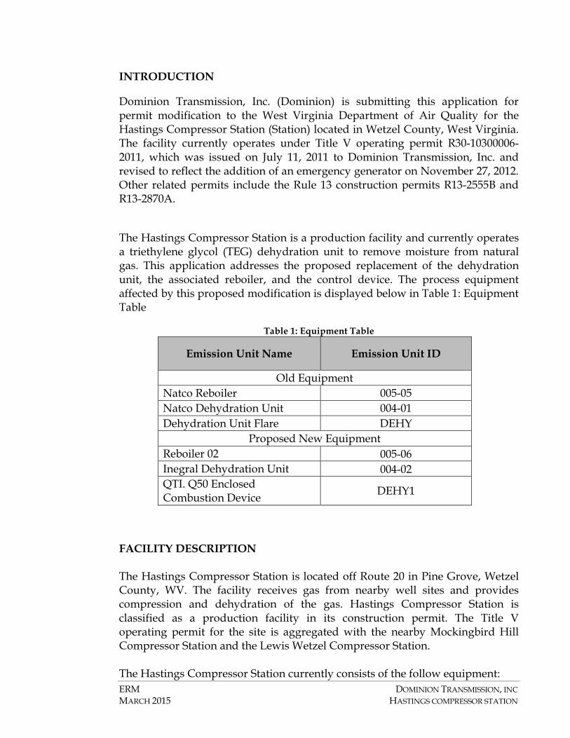
The Hastings Compressor Station is a production facility and currently operates a triethylene glycol (TEG) dehydration unit to remove moisture from natural gas. This application addresses the proposed replacement of the dehydration unit, the associated reboiler, and the control device. The process equipment affected by this proposed modification is displayed below in Table 1: Equipment Table
Table 1: Equipment Table
Emission Unit Name Emission Unit ID
Old Equipment Natco Reboiler 005-05 Natco Dehydration Unit 004-01 Dehydration Unit Flare DEHY
Proposed New Equipment Reboiler 02 005-06 Inegral Dehydration Unit 004-02 QTI. Q50 Enclosed Combustion Device DEHY1
FACILITY DESCRIPTION The Hastings Compressor Station is located off Route 20 in Pine Grove, Wetzel County, WV. The facility receives gas from nearby well sites and provides compression and dehydration of the gas. Hastings Compressor Station is classified as a production facility in its construction permit. The Title V operating permit for the site is aggregated with the nearby Mockingbird Hill Compressor Station and the Lewis Wetzel Compressor Station. The Hastings Compressor Station currently consists of the follow equipment:
ERM DOMINION TRANSMISSION, INC MARCH 2015 HASTINGS COMPRESSOR STATION
• Two (2) Cooper GMXE-6 engines each rated at 500 hp; • One (1) Generac QT080 Auxillary Generator rated at 128 hp (80 kW); • One (1) Natco Dehydration Unit rated at 7.5 MMscf/day; • One (1) Natco Reboiler rated at 0.38 MMBtu/hr; • One (1) Natco Heater rated at 10.0 MMBtu/hr; • One (1) Dehydration Unit Flare rate at 73 scf/min; and • Four (4) Tanks of various sizes for the storage of fluids.
The proposed modification would include the decommissioning of the Natco Dehydration Unit, the Natco Reboiler, and the Dehydration Unit Flare. To replace these units, Dominion is seeking approval to install:
• One (1) Inegral Dehydration Unit rated at 7.5 MMscf/day; • One (1) Diverse Energy Systems Reboiler rated at 0.55 MMBtu/hr; and • One (1) Questor Technologies Q50 Enclosed Combustion Device.
A process flow diagram is included in this application in Attachment D.
EXISTING PERMIT STATUS The major source thresholds for the West Virginia Title V operating permitting program, WV 45CSR30, are 100 tons per year of any regulated air pollutant, 10 tons per year of single HAP or 25 tons per year of aggregate HAPs. The aggregation of the Hastings Station, Mockingbird Hill Station, and Lewis Wetzel Station results in total Potential to Emit (PTE) that exceed the major source threshold for Nitrogen Oxides (NOx), Volatile Organic Compounds (VOCs), Carbon Monoxide (CO) and the PSD threshold NOx and VOCs. The facility is also currently classified as a major source of Hazardous Air Pollutants (HAPs), with a PTE of 32.3 tpy of aggregate HAPs.
REGULATORY DISCUSSION
This section outlines the State air quality regulations that could be reasonably expected to apply to the Hastings Compressor Station and makes an applicability determination for each regulation based on activities conducted at the Station and the emissions of regulated air pollutants associated with this project. This review is presented to supplement and/or add clarification to the information provided in the WVDAQ permit modification forms.
The West Virginia State Regulations address federal regulations, including Prevention of Significant Deterioration permitting, Title V permitting, New Source Performance Standards, and National Emission Standards for Hazardous
ERM DOMINION TRANSMISSION, INC MARCH 2015 HASTINGS COMPRESSOR STATION
Air Pollutants. The regulatory requirements in reference to the Hastings Compressor Station are described in detail in the below section.
WEST VIRGINIA STATE AIR REGULATIONS
45 CSR 02 – To Prevent and Control Particulate Air Pollution From Combustion of Fuel in Indirect Heat Exchangers
The reboiler proposed in this application is an indirect heat exchanger that combusts natural gas. However, it is exempt from this regulation since the heat input capacity is less than 10 MMBtu/hr.
45 CSR 04 – To Prevent and Control the Discharge of Air Pollutants into the Air Which Causes or Contributes to an Objectionable Odor
Operations conducted at the Hastings Compressor Station are subject to this requirement. Based on the nature of the process at the compressor station, the presence of objectionable odors is unlikely and this project is not expected to impact the ability to comply with 45 CSR 04.
45 CSR 06 – Control of Air Pollution from the Combustion of Refuse
The enclosed combustion device proposed at the Hastings Compressor Station is subject to this regulation. Per 45 CSR 6-4.3, opacity of emissions from the enclosed combustion devices shall not exceed 20 percent, except as provided by 6-4.4. Particulate matter emissions from these units will not exceed the levels calculated in accordance with 6-4.1. Where:
PMallowable (lb/hr) = F x Incinerator Capacity (tons/hr) DEHY1- PMallowable (lb/hr) = 86.09 lb/hr x 5.43 (F factor) x 1 ton/2000 lb = 0.23 tpy Where 89.09 pounds per hour is the maximum mass flowrate of wet gas, 5.43 is the F factor. Based upon AP-42, the enclosed combustion device will comply with the allowable PM emission limit determined in accordance with 45 CSR6-4.
ERM DOMINION TRANSMISSION, INC MARCH 2015 HASTINGS COMPRESSOR STATION
45 CSR 10 – To Prevent and Control Air Pollution From the Emission of Sulfur Oxides
The reboiler is an indirect heat exchanger that combusts natural gas but is exempt from this regulation since the heat input capacity is less than 10 MMBtu/hr.
45 CSR 13 – Permits for Construction, Modification, Relocation And Operation of Stationary Sources of Air Pollutants
This permit modification is being submitted to the WVDAQ to seek authorization for the operation of replacement equipment at the Hastings Compressor Station.
45 CSR 14 – Permits for Construction and Major Modification of Major Stationary Sources of Air Pollution for the Prevention of Significant Deterioration
The potential emissions from equipment at the Hastings Compressor Station, when aggregated with the Lewis Wetzel Station and Mockingbird Hill Station, exceed the Prevention of Significant Deterioration (PSD) emission thresholds for NO2 and VOCs. As such, the facility is a major source under PSD and any modifications must be reviewed to determine if they are considered major modifications under the 45 CSR 14. Per 45 CSR 14-2.74, a modification is considered to be major if it results in a net emission increase that would equal or exceed any of the following rates:
Pollutant Pollutant Emission Rate (tons/year)
Carbon monoxide: 100 tpy
Nitrogen oxides: 40 tpy
Sulfur dioxide: 40 tpy
Particulate matter: 25 tpy
PM10: 15 tpy
PM2.5: 10 tpy of direct PM2.5 emissions
PM2.5: 40 tpy of SO2 emissions
PM2.5: 40 tpy of NOX emissions (unless demonstrated not to be a PM2.5 precursor under subsection 2.66).
Ozone: 40 tpy of VOC or NOX
Lead: 0.6 tpy
Fluorides: 3 tpy
ERM DOMINION TRANSMISSION, INC MARCH 2015 HASTINGS COMPRESSOR STATION
Sulfuric acid mist: 7 tpy
Hydrogen sulfide (H2S):
10 tpy
Total reduced sulfur (including H2S):
10 tpy
Reduced sulfur compounds (including H2S):
10 tpy
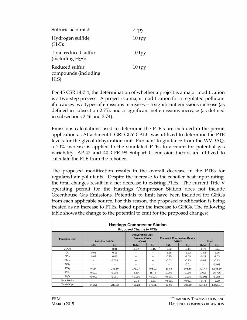
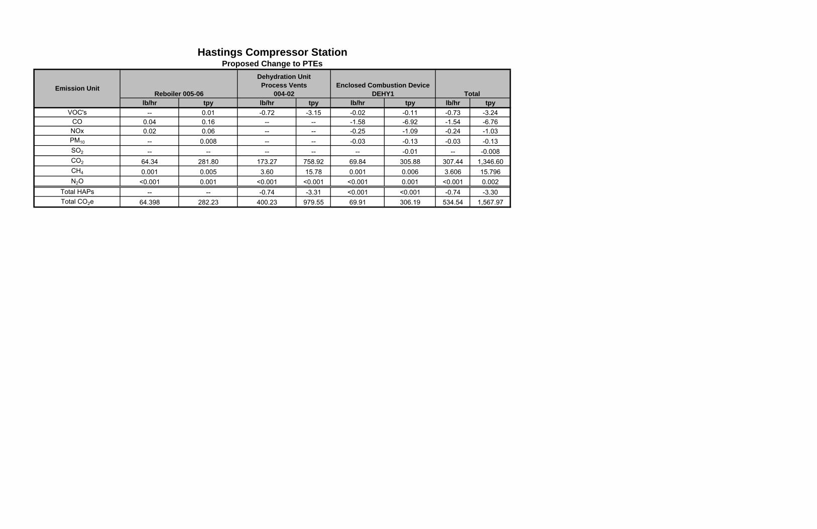
Per 45 CSR 14-3.4, the determination of whether a project is a major modification is a two-step process. A project is a major modification for a regulated pollutant if it causes two types of emissions increases -- a significant emissions increase (as defined in subsection 2.75), and a significant net emissions increase (as defined in subsections 2.46 and 2.74). Emissions calculations used to determine the PTE’s are included in the permit application as Attachment I. GRI GLY-CALC was utilized to determine the PTE levels for the glycol dehydration unit. Pursuant to guidance from the WVDAQ, a 20% increase is applied to the simulated PTEs to account for potential gas variability. AP-42 and 40 CFR 98 Subpart C emission factors are utilized to calculate the PTE from the reboiler. The proposed modification results in the overall decrease in the PTEs for regulated air pollutants. Despite the increase to the reboiler heat input rating, the total changes result in a net decrease to existing PTEs. The current Title V operating permit for the Hastings Compressor Station does not include Greenhouse Gas Emissions. Potentials to Emit have been included for GHGs from each applicable source. For this reason, the proposed modification is being treated as an increase to PTEs, based upon the increase to GHGs. The following table shows the change to the potential to emit for the proposed changes:
lb/hr tpy lb/hr tpy lb/hr tpy lb/hr tpyVOC's -- 0.01 -0.72 -3.15 -0.02 -0.11 -0.73 -3.24
CO 0.04 0.16 -- -- -1.58 -6.92 -1.54 -6.76NOx 0.02 0.06 -- -- -0.25 -1.09 -0.24 -1.03PM10 -- 0.008 -- -- -0.03 -0.13 -0.03 -0.13SO2 -- -- -- -- -- -0.01 -- -0.008CO2 64.34 281.80 173.27 758.92 69.84 305.88 307.44 1,346.60CH4 0.001 0.005 3.60 15.78 0.001 0.006 3.606 15.796N2O <0.001 0.001 <0.001 <0.001 <0.001 0.001 <0.001 0.002
Total HAPs -- -- -0.74 -3.31 <0.001 <0.001 -0.74 -3.30Total CO2e 64.398 282.23 400.23 979.55 69.91 306.19 534.54 1,567.97
Proposed Change to PTEs
Emission UnitReboiler 005-06
Dehydration UnitProcess Vents
004-02Enclosed Combustion Device
DEHY1 Total
Hastings Compressor Station
ERM DOMINION TRANSMISSION, INC MARCH 2015 HASTINGS COMPRESSOR STATION
Since the proposed project does not cause a significant emissions increase, the proposed modification of the dehydration unit qualifies as a minor permitting action and is not subject to the requirements of this rule.
45 CSR 16 - Standards of Performance for New Stationary Sources (NSPS)
45 CSR 16 applies to all registrants that are subject to any of the NSPS requirements codified in 40 CFR 60. A discussion of NSPS that could be reasonably anticipated to apply at the Station is provided in the Federal Regulatory Discussion. This project only impacts the dehydration unit at the Station and therefore, it has been determined that no NSPS requirements are triggered by the project.
45 CSR 19 – Permits for Construction and Major Modification of Major Stationary Sources of Air Pollution which Cause or Contributed to Non-attainment
Wetzel County, WV is in attainment for all pollutants with a National Ambient Air Quality Standard (NAAQS). Therefore, this regulation would not apply to the Hastings Compressor Station.
45 CSR 25 – Control of Air Pollution from Hazardous Waste Treatment, Storage, and Disposal Facilities
This Site does not qualify as a waste treatment, storage, and disposal facility and no hazardous waste will be burned at this Site; therefore, it is not subject to this hazardous waste rule.
45 CSR 30 – Requirements for Operating Permits
45 CSR 30 codifies the requirements of the federal Title V operating permit program (40 CFR 70) for West Virginia. The major source thresholds for the Title V operating permit program regulations are 10 tons per year (tpy) of a single hazardous air pollutant (HAP), 25 tpy of any combination of HAPs, or 100 tpy of all other regulated pollutants. The PTEs of VOCs, NOx, and CO are above the corresponding major source thresholds. The Hastings Station, Lewis Wetzel Station, and Mockingbird Hill Station qualify as major sources under the Title V program. The submission of this permit modification application will serve as the application for modification for the facilities’ Title V Operating Permit. An additional electronic copy of this application is included with this submission for distribution to the WVDAQ Title V Permitting Group.
45 CSR 34 – National Emission Standards for Hazardous Air Pollutants (NESHAP)
ERM DOMINION TRANSMISSION, INC MARCH 2015 HASTINGS COMPRESSOR STATION
45 CSR 34 applies to all registrants that are subject to any of the NESHAP requirements. The following NESHAP Rules are applicable to the proposed changes at the Hastings Compressor Station:
• 40 CFR 63 Subpart HH - National Emission Standards for Hazardous Air Pollutants from Oil and Natural Gas Production Facilities. Additional discussion is provided in the federal discussion of this permit application.
FEDERAL REGULATIONS
40 CFR 60, Subpart OOOO (Standards of Performance for Crude oil and Natural Gas Production, Transmission and Distribution)
Subpart OOOO establishes emission standards and compliance schedules for the control of volatile organic compounds (VOC) and sulfur dioxide (SO2) emissions from certain affected facilities that commence construction, modification or reconstruction after August 23, 2011. The proposed installation of the replacement dehydration unit neither involves installation of an affected facility as defined by Subpart OOOO, nor changes the facility status with respect to Subpart OOOO.
Similarly, no other NSPS are applicable to the proposed project.
40 CFR 63 Subpart HH (National Emission Standards for Hazardous Air Pollutants from Oil and Natural Gas Production Facilities).
Dominion is seeking a federally enforceable permit limitation on the control of emissions from the dehydration unit. This is allowable under West Virginia State Rules since the issued permit will require that the enclosed combustion device is operational at all times that a vent stream is present from the glycol process unit. The issuance of a federally enforceable permit limitation on the glycol process vents supports maintaining the classification of the Hastings Compressor Station as an area source of HAPs. The issuance of a federally enforceable permit limit on the control of emissions needs to be issued by October 15, 2015.
An area source of HAPs is defined as a facility that has a PTE of less than 10 tons per year of any single HAP, and less than 25 tpy of aggregate HAPs. The Hastings Compressor Station has been determined to be an area source of HAPs, since a major source HAP determination is completed for each surface site. Despite the aggregation of the Hastings, Lewis Wetzel, and Mockingbird Hill facilities in the Title V Operating Permit, these facilities are considered separate surface sites under 40 CFR 63. For this reason, the Hastings Compressor Station
ERM DOMINION TRANSMISSION, INC MARCH 2015 HASTINGS COMPRESSOR STATION
qualifies as an area source facility that operates a 40 CFR 63 Section HH affected source, the dehydration unit.
The existing Title V Permit indicates that the Hastings Compressor Station is not located in an Urban-1 county, as defined in §63.761. The designation of a facility operating in a non-Urban county is made from data found in the 2000 US census. Since more recent census data has not become available since the issuance of this permit, there is no change to the urban classification of Pine Grove, West Virginia. Dominion has conducted the required analysis of PTE emissions from the affected source and determined that the facility is eligible to claim the benzene exemption under §63.764(e)(1)(ii), since the actual average emissions of benzene from the glycol dehydration unit process vent to the atmosphere is less than 0.90 megagrams. This applicability determination has been made utilizing controlled PTE values since Dominion is seeking a federally enforceable permit limitation that will require that all vapors from the glycol process unit be routed to the enclosed combustion device. The total benzene emissions for this proposed modification, as demonstrated in the GLY-CALC simulation provided as a part of this permit application, are 0.11 tons per year of benzene, which is equal to 0.10 megagrams of benzene. Since Dominion is claiming the benzene exemption under 63.764(e)(1)(ii), Dominion does not have to comply with control requirements for glycol dehydration unit process vents in 63.765.
Based upon this regulatory applicability analysis, Dominion is only required to comply with §63.772(b)(2) and conduct a determination of glycol dehydration unit flow rate or benzene emissions. This requires that Dominion makes a determination of actual average benzene or BTEX emissions from a glycol dehydration unit using an acceptable procedure under the Rule. This determination will be made using GRI GLY-CALC utilizing inputs that are representative of actual operating conditions. Records of actual natural gas throughput and actual average benzene emissions will be kept pursuant to §63.774(d)(1).
CAM Applicability Requirements Summary
40 CFR Part 64 applies to pollutant specific emissions at a major source. An applicability determination has been made as a part of this permit application.
The Hastings Compressor Station qualifies under 40 CFR §64.2(a) as a unit that is located at a major source that is required to obtain a Title V permit. The Station also is subject to an emissions limit or standard for an applicable pollutant (40 CFR §64.2(a)(1)), uses a control device to achieve compliance with an applicable limitation or standard(40 CFR §64.2(a)(2)), and the potential pre-
ERM DOMINION TRANSMISSION, INC MARCH 2015 HASTINGS COMPRESSOR STATION
control emissions of the applicable pollutant from the unit is greater than 100 tpy of VOCs.
The Hastings Compressor Station, however, is exempt from the requirements of 40 CFR Part 64 since §64.2(b)(i) states that the requirements of Part 64 do not apply if, “Emission limitations or standards proposed by the Administrator after November 15, 1990 pursuant to section 111 or 112 of the Act.” The Hastings Compressor Station currently operates under Title V Permit R30-10300006-2011, where CAM rule non-applicability was determined during the Title V operating permit renewal application. The proposed modifications included in this permit application will not have an effect on the CAM applicability for the Hastings Compressor Station.
NSR/Title V Permit Revision Application Form (Revision form.doc) Revised - 05/2010
Page 1 of 4
WEST VIRGINIA DEPARTMENT OF ENVIRONMENTAL PROTECTION
DIVISION OF AIR QUALITY 601 57th Street, SE
Charleston, WV 25304 (304) 926-0475
www.dep.wv.gov/daq
APPLICATION FOR NSR PERMIT
AND
TITLE V PERMIT REVISION (OPTIONAL)
PLEASE CHECK ALL THAT APPLY TO NSR (45CSR13) (IF KNOWN):
CONSTRUCTION MODIFICATION RELOCATION
CLASS I ADMINISTRATIVE UPDATE TEMPORARY
CLASS II ADMINISTRATIVE UPDATE AFTER-THE-FACT
PLEASE CHECK TYPE OF 45CSR30 (TITLE V) REVISION (IF ANY):
ADMINISTRATIVE AMENDMENT MINOR MODIFICATION SIGNIFICANT MODIFICATION
IF ANY BOX ABOVE IS CHECKED, INCLUDE TITLE V REVISION INFORMATION AS ATTACHMENT S TO THIS APPLICATION
FOR TITLE V FACILITIES ONLY: Please refer to “Title V Revision Guidance” in order to determine your Title V Revision options (Appendix A, “Title V Permit Revision Flowchart”) and ability to operate with the changes requested in this Permit Application.
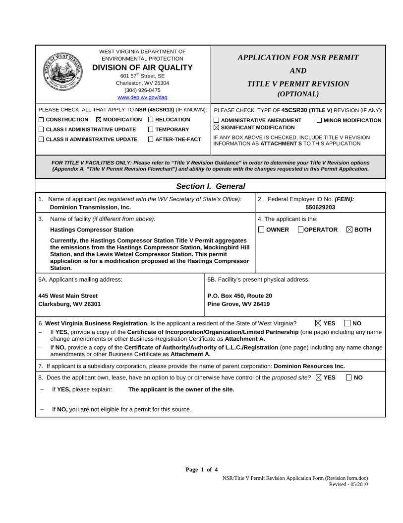
Section I. General 1. Name of applicant (as registered with the WV Secretary of State’s Office): Dominion Transmission, Inc.
2. Federal Employer ID No. (FEIN): 550629203
3. Name of facility (if different from above):
Hastings Compressor Station
Currently, the Hastings Compressor Station Title V Permit aggregates the emissions from the Hastings Compressor Station, Mockingbird Hill Station, and the Lewis Wetzel Compressor Station. This permit application is for a modification proposed at the Hastings Compressor Station.
4. The applicant is the:
OWNER OPERATOR BOTH
5A. Applicant’s mailing address: 445 West Main Street Clarksburg, WV 26301
5B. Facility’s present physical address: P.O. Box 450, Route 20 Pine Grove, WV 26419
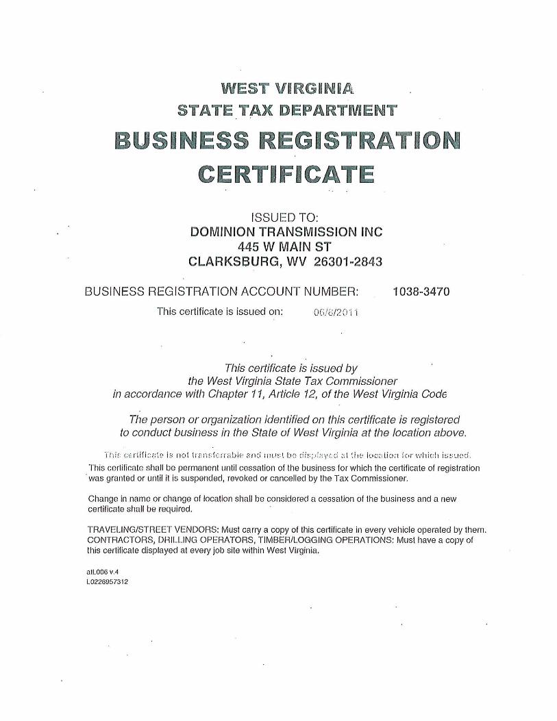
6. West Virginia Business Registration. Is the applicant a resident of the State of West Virginia? YES NO − If YES, provide a copy of the Certificate of Incorporation/Organization/Limited Partnership (one page) including any name
change amendments or other Business Registration Certificate as Attachment A. − If NO, provide a copy of the Certificate of Authority/Authority of L.L.C./Registration (one page) including any name change
amendments or other Business Certificate as Attachment A.
7. If applicant is a subsidiary corporation, please provide the name of parent corporation: Dominion Resources Inc.
8. Does the applicant own, lease, have an option to buy or otherwise have control of the proposed site? YES NO
− If YES, please explain: The applicant is the owner of the site.
− If NO, you are not eligible for a permit for this source.
NSR/Title V Permit Revision Application Form (Revision form.doc) Revised - 05/2010
Page 1 of 4
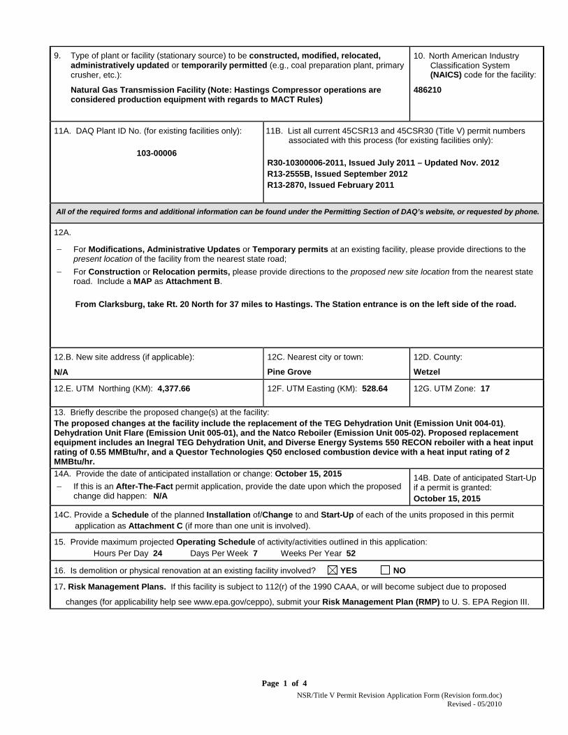
9. Type of plant or facility (stationary source) to be constructed, modified, relocated, administratively updated or temporarily permitted (e.g., coal preparation plant, primary crusher, etc.):
Natural Gas Transmission Facility (Note: Hastings Compressor operations are considered production equipment with regards to MACT Rules)
10. North American Industry Classification System (NAICS) code for the facility:
486210
11A. DAQ Plant ID No. (for existing facilities only):
103-00006
11B. List all current 45CSR13 and 45CSR30 (Title V) permit numbers associated with this process (for existing facilities only):
R30-10300006-2011, Issued July 2011 – Updated Nov. 2012 R13-2555B, Issued September 2012 R13-2870, Issued February 2011
All of the required forms and additional information can be found under the Permitting Section of DAQ’s website, or requested by phone.
12A.
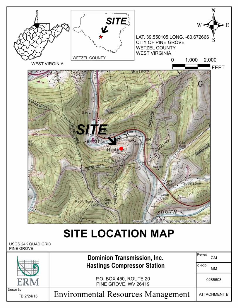
− For Modifications, Administrative Updates or Temporary permits at an existing facility, please provide directions to the present location of the facility from the nearest state road;
− For Construction or Relocation permits, please provide directions to the proposed new site location from the nearest state road. Include a MAP as Attachment B.
From Clarksburg, take Rt. 20 North for 37 miles to Hastings. The Station entrance is on the left side of the road.
12.B. New site address (if applicable):
N/A
12C. Nearest city or town:
Pine Grove
12D. County:
Wetzel
12.E. UTM Northing (KM): 4,377.66 12F. UTM Easting (KM): 528.64 12G. UTM Zone: 17
13. Briefly describe the proposed change(s) at the facility: The proposed changes at the facility include the replacement of the TEG Dehydration Unit (Emission Unit 004-01), Dehydration Unit Flare (Emission Unit 005-01), and the Natco Reboiler (Emission Unit 005-02). Proposed replacement equipment includes an Inegral TEG Dehydration Unit, and Diverse Energy Systems 550 RECON reboiler with a heat input rating of 0.55 MMBtu/hr, and a Questor Technologies Q50 enclosed combustion device with a heat input rating of 2 MMBtu/hr. 14A. Provide the date of anticipated installation or change: October 15, 2015 − If this is an After-The-Fact permit application, provide the date upon which the proposed
change did happen: N/A
14B. Date of anticipated Start-Up if a permit is granted: October 15, 2015
14C. Provide a Schedule of the planned Installation of/Change to and Start-Up of each of the units proposed in this permit application as Attachment C (if more than one unit is involved).
15. Provide maximum projected Operating Schedule of activity/activities outlined in this application: Hours Per Day 24 Days Per Week 7 Weeks Per Year 52
16. Is demolition or physical renovation at an existing facility involved? YES NO
17. Risk Management Plans. If this facility is subject to 112(r) of the 1990 CAAA, or will become subject due to proposed
changes (for applicability help see www.epa.gov/ceppo), submit your Risk Management Plan (RMP) to U. S. EPA Region III.
NSR/Title V Permit Revision Application Form (Revision form.doc) Revised - 05/2010
Page 2 of 4
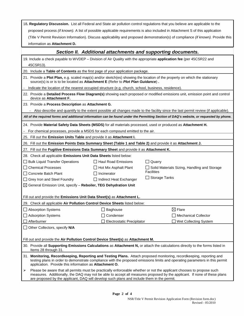
18. Regulatory Discussion. List all Federal and State air pollution control regulations that you believe are applicable to the
proposed process (if known). A list of possible applicable requirements is also included in Attachment S of this application
(Title V Permit Revision Information). Discuss applicability and proposed demonstration(s) of compliance (if known). Provide this
information as Attachment D.
Section II. Additional attachments and supporting documents. 19. Include a check payable to WVDEP – Division of Air Quality with the appropriate application fee (per 45CSR22 and
45CSR13).
20. Include a Table of Contents as the first page of your application package.
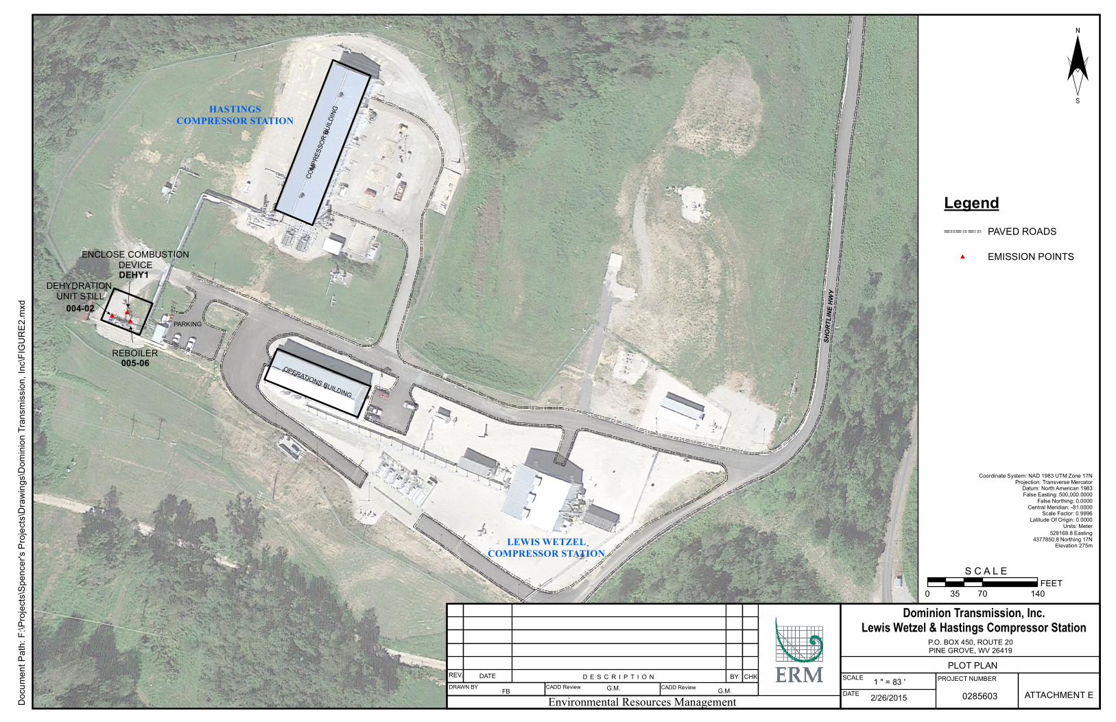
21. Provide a Plot Plan, e.g. scaled map(s) and/or sketch(es) showing the location of the property on which the stationary source(s) is or is to be located as Attachment E (Refer to Plot Plan Guidance) .
− Indicate the location of the nearest occupied structure (e.g. church, school, business, residence).
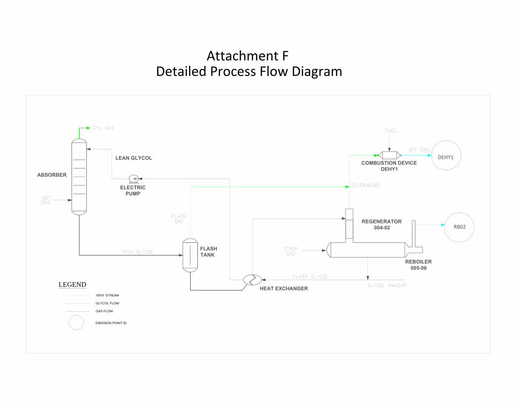
22. Provide a Detailed Process Flow Diagram(s) showing each proposed or modified emissions unit, emission point and control device as Attachment F.
23. Provide a Process Description as Attachment G.
− Also describe and quantify to the extent possible all changes made to the facility since the last permit review (if applicable). All of the required forms and additional information can be found under the Permitting Section of DAQ’s website, or requested by phone.
24. Provide Material Safety Data Sheets (MSDS) for all materials processed, used or produced as Attachment H.
− For chemical processes, provide a MSDS for each compound emitted to the air.
25. Fill out the Emission Units Table and provide it as Attachment I. 26. Fill out the Emission Points Data Summary Sheet (Table 1 and Table 2) and provide it as Attachment J. 27. Fill out the Fugitive Emissions Data Summary Sheet and provide it as Attachment K. 28. Check all applicable Emissions Unit Data Sheets listed below:
Bulk Liquid Transfer Operations Chemical Processes Concrete Batch Plant Grey Iron and Steel Foundry
Haul Road Emissions Hot Mix Asphalt Plant Incinerator Indirect Heat Exchanger
Quarry Solid Materials Sizing, Handling and Storage
Facilities Storage Tanks
General Emission Unit, specify – Reboiler, TEG Dehydration Unit Fill out and provide the Emissions Unit Data Sheet(s) as Attachment L.
29. Check all applicable Air Pollution Control Device Sheets listed below:
Absorption Systems Adsorption Systems Afterburner
Baghouse Condenser Electrostatic Precipitator
Flare Mechanical Collector Wet Collecting System
Other Collectors, specify N/A
Fill out and provide the Air Pollution Control Device Sheet(s) as Attachment M.
30. Provide all Supporting Emissions Calculations as Attachment N, or attach the calculations directly to the forms listed in Items 28 through 31.
31. Monitoring, Recordkeeping, Reporting and Testing Plans. Attach proposed monitoring, recordkeeping, reporting and testing plans in order to demonstrate compliance with the proposed emissions limits and operating parameters in this permit application. Provide this information as Attachment O.
Please be aware that all permits must be practically enforceable whether or not the applicant chooses to propose such measures. Additionally, the DAQ may not be able to accept all measures proposed by the applicant. If none of these plans are proposed by the applicant, DAQ will develop such plans and include them in the permit.
NSR/Title V Permit Revision Application Form (Revision form.doc) Revised - 05/2010
Page 4 of 4
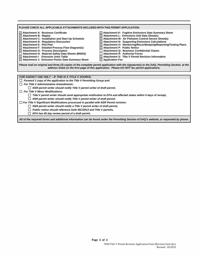
PLEASE CHECK ALL APPLICABLE ATTACHMENTS INCLUDED WITH THIS PERMIT APPLICATION:
Attachment A: Business Certificate Attachment B: Map(s) Attachment C: Installation and Start Up Schedule Attachment D: Regulatory Discussion Attachment E: Plot Plan Attachment F: Detailed Process Flow Diagram(s) Attachment G: Process Description Attachment H: Material Safety Data Sheets (MSDS) Attachment I: Emission Units Table Attachment J: Emission Points Data Summary Sheet
Attachment K: Fugitive Emissions Data Summary Sheet Attachment L: Emissions Unit Data Sheet(s) Attachment M: Air Pollution Control Device Sheet(s) Attachment N: Supporting Emissions Calculations Attachment O: Monitoring/Recordkeeping/Reporting/Testing Plans Attachment P: Public Notice Attachment Q: Business Confidential Claims Attachment R: Authority Forms Attachment S: Title V Permit Revision Information Application Fee
Please mail an original and three (3) copies of the complete permit application with the signature(s) to the DAQ, Permitting Section, at the address listed on the first page of this application. Please DO NOT fax permit applications.
FOR AGENCY USE ONLY – IF THIS IS A TITLE V SOURCE: Forward 1 copy of the application to the Title V Permitting Group and: For Title V Administrative Amendments:
NSR permit writer should notify Title V permit writer of draft permit, For Title V Minor Modifications:
Title V permit writer should send appropriate notification to EPA and affected states within 5 days of receipt, NSR permit writer should notify Title V permit writer of draft permit.
For Title V Significant Modifications processed in parallel with NSR Permit revision: NSR permit writer should notify a Title V permit writer of draft permit, Public notice should reference both 45CSR13 and Title V permits, EPA has 45 day review period of a draft permit.
All of the required forms and additional information can be found under the Permitting Section of DAQ’s website, or requested by phone.
Table of Contents
ATTACHMENT A BUSINESS CERTIFICATE ATTACHMENT B LOCATION MAP ATTACHMENT C SCHEDULE OF CHANGES
ATTACHMENT D REGULATORY DISCUSSION ATTACHMENT E PLOT PLAN ATTACHMENT F DETAILED PROCESS FLOW DIAGRAMS ATTACHMENT G PROCESS DESCRIPTION ATTACHMENT I EQUIPMENT LIST FORM ATTACHMENT J EMISSION POINTS DATA SUMMARY SHEET ATTACHMENT K FUGITIVE EMISSIONS DATA SUMMARY SHEET ATTACHMENT L EMISSIONS UNIT DATA SHEETS ATTACHMENT M AIR POLLUTION CONTROL DEVICE SHEETS ATTACHMENT N SUPPORTING EMISSIONS CALCULATIONS ATTACHMENT O MONITORING, REPORTING, AND RECORDKEEPING PLAN ATTACHMENT P PUBLIC NOTICE ATTACHMENT S TITLE V PERMIT Attachments H, Q, and R are not applicable to this application and are not provided.

Attachment A BUSINESS CERTIFICATE

Attachment B LOCATION MAP
d!
Copyright:© 2013 National Geographic Society, i-cubed
Environmental Resources ManagementDrawn ByFB 2/24/15 ATTACHMENT B
0285603
Dominion Transmission, Inc.Hastings Compressor Station
P.O. BOX 450, ROUTE 20PINE GROVE, WV 26419
_̂
dSITE
SITE LOCATION MAP
0 2,0001,000FEET
LAT. 39.550105 LONG. -80.672666CITY OF PINE GROVEWETZEL COUNTYWEST VIRGINIA
.WEST VIRGINIA
USGS 24K QUAD GRIDPINE GROVE
Review
CHK'D GM
GM
WETZEL COUNTY
SITE

Attachment C Schedule of Changes

Page 1 of 1
Attachment C Schedule of Changes
Dominion Transmission, Inc. proposes that the modification equipment be permitted to install and operate as soon as possible, but no later than October 15, 2015.
Attachment D REGULATORY DISCUSSION
Page 1 of 1
Attachment D Regulatory Discussion
Dominion Transmission, Inc. has included a State and Federal Regulatory discussion in the introduction to this permit application.

Attachment E PLOT PLAN
##
#
SHOR
TLIN
E HWY
COMP
RESS
OR BU
ILDIN
G
OPERATIONS BUILDING
Docu
ment
Path:
F:\Pr
ojects
\Spen
cer's
Proje
cts\D
rawing
s\Dom
inion
Tran
smiss
ion, In
c\FIG
URE2
.mxd
Dominion Transmission, Inc.Lewis Wetzel & Hastings Compressor Station
P.O. BOX 450, ROUTE 20PINE GROVE, WV 26419
¨
0 70 14035FEET
S C A L E
2/26/2015Environmental Resources Management
Coordinate System: NAD 1983 UTM Zone 17NProjection: Transverse Mercator
Datum: North American 1983False Easting: 500,000.0000
False Northing: 0.0000Central Meridian: -81.0000
Scale Factor: 0.9996Latitude Of Origin: 0.0000
Units: Meter
SCALE 1 " = 83 'DATE
PROJECT NUMBER
0285603 ATTACHMENT EDATEREV. BY CHKD E S C R I P T I O N
DRAWN BY CADD Review CADD ReviewFB G.M. G.M.
LegendPAVED ROADS
# EMISSION POINTSENCLOSE COMBUSTIONDEVICE
REBOILER
DEHYDRATION UNIT STILL
005-06
DEHY1
004-02PARKING
528168.8 Easting4377850.8 Northing 17N
Elevation 275m
PLOT PLAN
LEWIS WETZELCOMPRESSOR STATION
HASTINGSCOMPRESSOR STATION
Attachment F DETAILED PROCESS FLOW DIAGRAM
ABSORBER
ELECTRIC
PUMP
LEAN GLYCOL
FLASH
TANK
HEAT EXCHANGER
REBOILER
005-06
COMBUSTION DEVICE
DEHY1
REGENERATOR
004-02
DEHY1
RB02
Attachment FDetailed Process Flow Diagram
LEGENDVENT STREAM
GLYCOL FLOW
GAS FLOW
EMISSION POINT ID

Attachment G PROCESS DESCRIPTION
Page 1 of 1
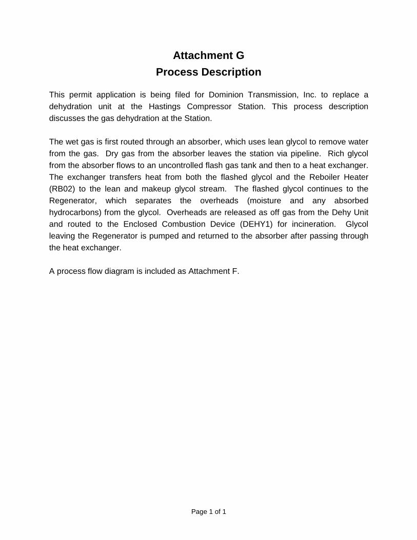
Attachment G Process Description
This permit application is being filed for Dominion Transmission, Inc. to replace a dehydration unit at the Hastings Compressor Station. This process description discusses the gas dehydration at the Station. The wet gas is first routed through an absorber, which uses lean glycol to remove water from the gas. Dry gas from the absorber leaves the station via pipeline. Rich glycol from the absorber flows to an uncontrolled flash gas tank and then to a heat exchanger. The exchanger transfers heat from both the flashed glycol and the Reboiler Heater (RB02) to the lean and makeup glycol stream. The flashed glycol continues to the Regenerator, which separates the overheads (moisture and any absorbed hydrocarbons) from the glycol. Overheads are released as off gas from the Dehy Unit and routed to the Enclosed Combustion Device (DEHY1) for incineration. Glycol leaving the Regenerator is pumped and returned to the absorber after passing through the heat exchanger. A process flow diagram is included as Attachment F.

Attachment I EQUIPMENT LIST FORM
Emission Units Table Page 1 of 1 03/2007
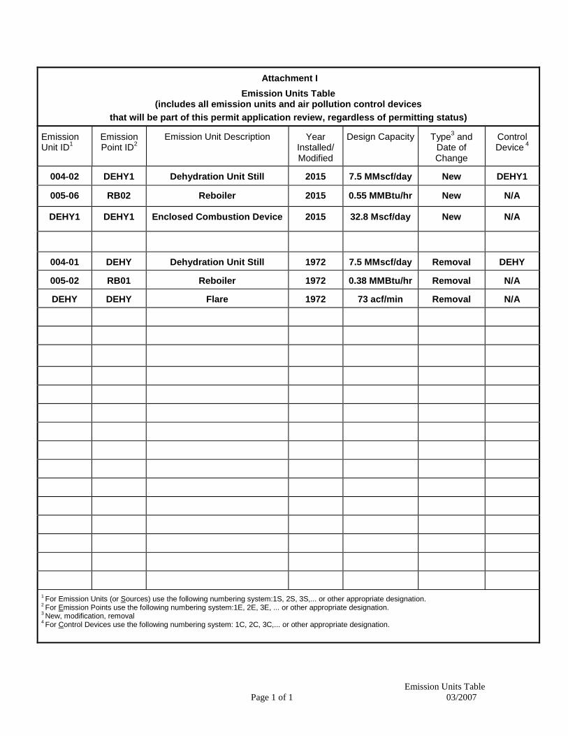
Attachment I Emission Units Table
(includes all emission units and air pollution control devices that will be part of this permit application review, regardless of permitting status)
Emission Unit ID1
Emission Point ID2
Emission Unit Description Year Installed/ Modified
Design Capacity Type3 and Date of Change
Control Device 4
004-02 DEHY1 Dehydration Unit Still 2015 7.5 MMscf/day New DEHY1
005-06 RB02 Reboiler 2015 0.55 MMBtu/hr New N/A
DEHY1 DEHY1 Enclosed Combustion Device 2015 32.8 Mscf/day New N/A
004-01 DEHY Dehydration Unit Still 1972 7.5 MMscf/day Removal DEHY
005-02 RB01 Reboiler 1972 0.38 MMBtu/hr Removal N/A
DEHY DEHY Flare 1972 73 acf/min Removal N/A
1 For Emission Units (or Sources) use the following numbering system:1S, 2S, 3S,... or other appropriate designation. 2 For Emission Points use the following numbering system:1E, 2E, 3E, ... or other appropriate designation. 3 New, modification, removal 4 For Control Devices use the following numbering system: 1C, 2C, 3C,... or other appropriate designation.
Attachment J EMISSION POINTS DATA SUMMARY SHEET
Page 1 of 2 WVDEP-DAQ Revision 2/11
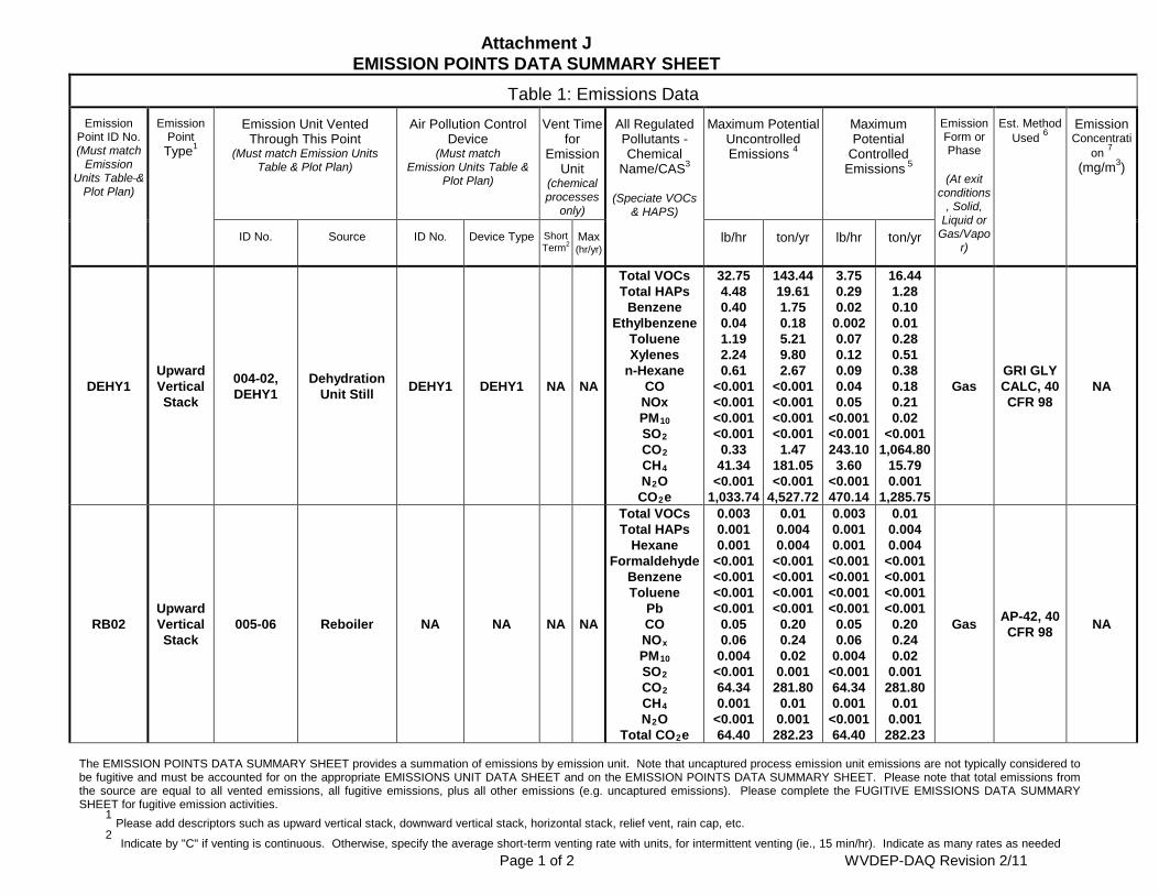
Attachment J EMISSION POINTS DATA SUMMARY SHEET
Table 1: Emissions Data Emission
Point ID No. (Must match
Emission Units Table &
Plot Plan)
Emission Point
Type1
Emission Unit Vented Through This Point
(Must match Emission Units Table & Plot Plan)
Air Pollution Control Device
(Must match Emission Units Table &
Plot Plan)
Vent Time for
Emission Unit
(chemical processes
only)
All Regulated Pollutants - Chemical
Name/CAS3
(Speciate VOCs & HAPS)
Maximum Potential Uncontrolled Emissions 4
Maximum Potential
Controlled Emissions 5
Emission Form or Phase
(At exit
conditions, Solid,
Liquid or Gas/Vapo
r)
Est. Method Used 6
Emission Concentrati
on 7 (mg/m3)
ID No. Source ID No. Device Type Short Term2
Max (hr/yr)
lb/hr ton/yr lb/hr ton/yr
DEHY1 Upward Vertical Stack
004-02, DEHY1
Dehydration Unit Still DEHY1 DEHY1 NA NA
Total VOCs Total HAPs
Benzene Ethylbenzene
Toluene Xylenes
n-Hexane CO
NOx PM10 SO2 CO2 CH4 N2O
CO2e
32.75 4.48 0.40 0.04 1.19 2.24 0.61
<0.001 <0.001 <0.001 <0.001
0.33 41.34
<0.001 1,033.74
143.44 19.61 1.75 0.18 5.21 9.80 2.67
<0.001 <0.001 <0.001 <0.001
1.47 181.05 <0.001
4,527.72
3.75 0.29 0.02
0.002 0.07 0.12 0.09 0.04 0.05
<0.001 <0.001 243.10
3.60 <0.001 470.14
16.44 1.28 0.10 0.01 0.28 0.51 0.38 0.18 0.21 0.02
<0.001 1,064.80
15.79 0.001
1,285.75
Gas GRI GLY CALC, 40 CFR 98
NA
RB02 Upward Vertical Stack
005-06 Reboiler NA NA NA NA
Total VOCs Total HAPs
Hexane Formaldehyde
Benzene Toluene
Pb CO NOx PM10 SO2 CO2 CH4 N2O
Total CO2e
0.003 0.001 0.001
<0.001 <0.001 <0.001 <0.001
0.05 0.06
0.004 <0.001 64.34 0.001
<0.001 64.40
0.01 0.004 0.004
<0.001 <0.001 <0.001 <0.001
0.20 0.24 0.02
0.001 281.80
0.01 0.001
282.23
0.003 0.001 0.001
<0.001 <0.001 <0.001 <0.001
0.05 0.06
0.004 <0.001 64.34 0.001
<0.001 64.40
0.01 0.004 0.004
<0.001 <0.001 <0.001 <0.001
0.20 0.24 0.02
0.001 281.80
0.01 0.001
282.23
Gas AP-42, 40 CFR 98 NA
The EMISSION POINTS DATA SUMMARY SHEET provides a summation of emissions by emission unit. Note that uncaptured process emission unit emissions are not typically considered to be fugitive and must be accounted for on the appropriate EMISSIONS UNIT DATA SHEET and on the EMISSION POINTS DATA SUMMARY SHEET. Please note that total emissions from the source are equal to all vented emissions, all fugitive emissions, plus all other emissions (e.g. uncaptured emissions). Please complete the FUGITIVE EMISSIONS DATA SUMMARY SHEET for fugitive emission activities. 1 Please add descriptors such as upward vertical stack, downward vertical stack, horizontal stack, relief vent, rain cap, etc. 2 Indicate by "C" if venting is continuous. Otherwise, specify the average short-term venting rate with units, for intermittent venting (ie., 15 min/hr). Indicate as many rates as needed
Page 2 of 2 WVDEP-DAQ Revision 2/11
to clarify frequency of venting (e.g., 5 min/day, 2 days/wk). 3
List all regulated air pollutants. Speciate VOCs, including all HAPs. Follow chemical name with Chemical Abstracts Service (CAS) number. LIST Acids, CO, CS2, VOCs, H2S, Inorganics, Lead, Organics, O3, NO, NO2, SO2, SO3, all applicable Greenhouse Gases (including CO2 and methane), etc. DO NOT LIST H2, H2O, N2, O2, and Noble Gases.
4 Give maximum potential emission rate with no control equipment operating. If emissions occur for less than 1 hr, then record emissions per batch in minutes (e.g. 5 lb VOC/20
minute batch). 5 Give maximum potential emission rate with proposed control equipment operating. If emissions occur for less than 1 hr, then record emissions per batch in minutes (e.g. 5 lb
VOC/20 minute batch). 6
Indicate method used to determine emission rate as follows: MB = material balance; ST = stack test (give date of test); EE = engineering estimate; O = other (specify). 7 Provide for all pollutant emissions. Typically, the units of parts per million by volume (ppmv) are used. If the emission is a mineral acid (sulfuric, nitric, hydrochloric or phosphoric)
use units of milligram per dry cubic meter (mg/m3) at standard conditions (68 °F and 29.92 inches Hg) (see 45CSR7). If the pollutant is SO2, use units of ppmv (See 45CSR10). Attachment J
EMISSION POINTS DATA SUMMARY SHEET
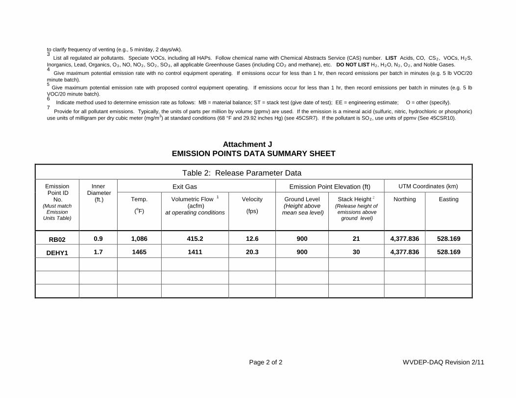
Table 2: Release Parameter Data
Emission Point ID
No. (Must match
Emission Units Table)
Inner Diameter
(ft.)
Exit Gas Emission Point Elevation (ft) UTM Coordinates (km)
Temp.
(oF)
Volumetric Flow 1 (acfm)
at operating conditions
Velocity
(fps)
Ground Level (Height above
mean sea level)
Stack Height 2 (Release height of emissions above
ground level)
Northing Easting
RB02 0.9 1,086 415.2 12.6 900 21 4,377.836 528.169
DEHY1 1.7 1465 1411 20.3 900 30 4,377.836 528.169
Attachment K FUGITIVE EMISSIONS DATA SUMMARY SHEET

Attachment L EMISSION UNIT DATA SHEETS
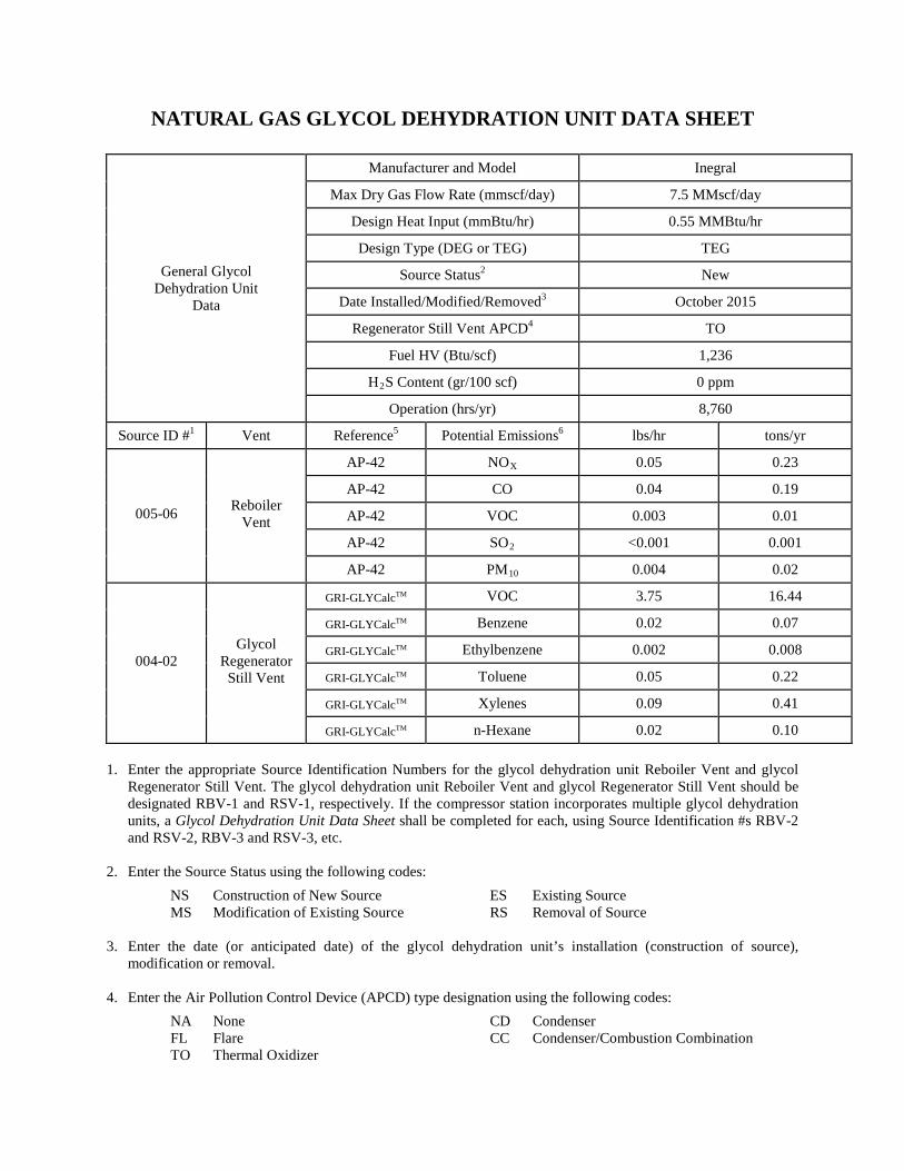
NATURAL GAS GLYCOL DEHYDRATION UNIT DATA SHEET
General Glycol
Dehydration Unit Data
Manufacturer and Model
Inegral
Max Dry Gas Flow Rate (mmscf/day)
7.5 MMscf/day
Design Heat Input (mmBtu/hr)
0.55 MMBtu/hr
Design Type (DEG or TEG)
TEG
Source Status2
New
Date Installed/Modified/Removed3
October 2015
Regenerator Still Vent APCD4
TO
Fuel HV (Btu/scf)
1,236
H2S Content (gr/100 scf)
0 ppm
Operation (hrs/yr)
8,760 Source ID #1
Vent
Reference5
Potential Emissions6
lbs/hr
tons/yr
005-06 Reboiler Vent
AP-42
NOX
0.05
0.23
AP-42
CO
0.04
0.19
AP-42
VOC
0.003
0.01
AP-42
SO2
<0.001
0.001
AP-42
PM10
0.004
0.02
004-02 Glycol
Regenerator Still Vent
GRI-GLYCalcTM
VOC 3.75 16.44
GRI-GLYCalcTM
Benzene 0.02 0.07
GRI-GLYCalcTM
Ethylbenzene 0.002 0.008
GRI-GLYCalcTM
Toluene 0.05 0.22
GRI-GLYCalcTM
Xylenes 0.09 0.41
GRI-GLYCalcTM
n-Hexane 0.02 0.10
1. Enter the appropriate Source Identification Numbers for the glycol dehydration unit Reboiler Vent and glycol
Regenerator Still Vent. The glycol dehydration unit Reboiler Vent and glycol Regenerator Still Vent should be designated RBV-1 and RSV-1, respectively. If the compressor station incorporates multiple glycol dehydration units, a Glycol Dehydration Unit Data Sheet shall be completed for each, using Source Identification #s RBV-2 and RSV-2, RBV-3 and RSV-3, etc.
2. Enter the Source Status using the following codes:
NS Construction of New Source ES Existing Source MS Modification of Existing Source RS Removal of Source
3. Enter the date (or anticipated date) of the glycol dehydration unit’s installation (construction of source),
modification or removal. 4. Enter the Air Pollution Control Device (APCD) type designation using the following codes:
NA None CD Condenser FL Flare CC Condenser/Combustion Combination
TO Thermal Oxidizer
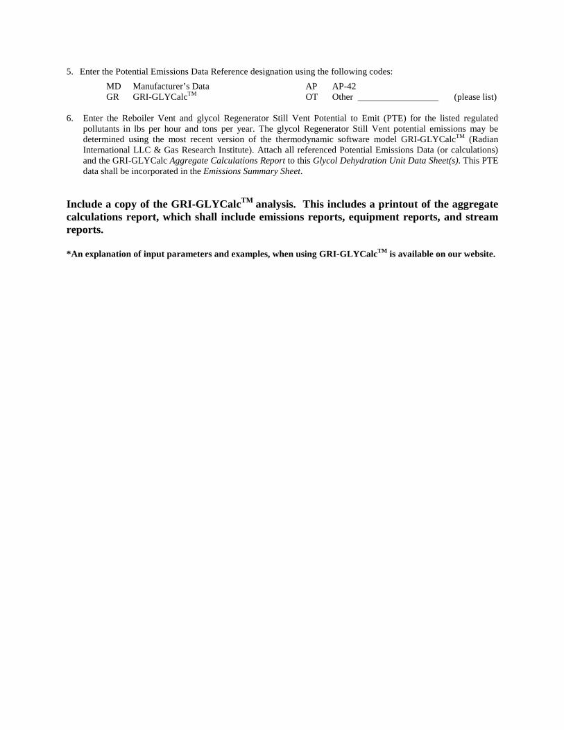
5. Enter the Potential Emissions Data Reference designation using the following codes: MD Manufacturer’s Data AP AP-42 GR GRI-GLYCalcTM OT Other (please list)
6. Enter the Reboiler Vent and glycol Regenerator Still Vent Potential to Emit (PTE) for the listed regulated
pollutants in lbs per hour and tons per year. The glycol Regenerator Still Vent potential emissions may be determined using the most recent version of the thermodynamic software model GRI-GLYCalcTM (Radian International LLC & Gas Research Institute). Attach all referenced Potential Emissions Data (or calculations) and the GRI-GLYCalc Aggregate Calculations Report to this Glycol Dehydration Unit Data Sheet(s). This PTE data shall be incorporated in the Emissions Summary Sheet.
Include a copy of the GRI-GLYCalcTM analysis. This includes a printout of the aggregate calculations report, which shall include emissions reports, equipment reports, and stream reports. *An explanation of input parameters and examples, when using GRI-GLYCalcTM is available on our website.
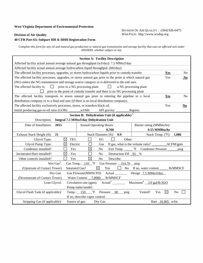
West Virginia Department of Environmental Protection
Division of Air Quality 40 CFR Part 63; Subpart HH & HHH Registration Form
DIVISION OF AIR QUALITY : (304) 926-0475 WEB PAGE: http:\\www.wvdep.org
Complete this form for any oil and natural gas production or natural gas transmission and storage facility that uses an affected unit under
HH/HHH, whether subject or not.
Section A: Facility Description Affected facility actual annual average natural gas throughput (scf/day): 7.5 MMscf/day Affected facility actual annual average hydrocarbon liquid throughput: (bbl/day): The affected facility processes, upgrades, or stores hydrocarbon liquids prior to custody transfer. Yes No The affected facility processes, upgrades, or stores natural gas prior to the point at which natural gas (NG) enters the NG transmission and storage source category or is delivered to the end user. The affected facility is: prior to a NG processing plant a NG processing plant prior to the point of custody transfer and there is no NG processing plant
Yes No
The affected facility transports or stores natural gas prior to entering the pipeline to a local distribution company or to a final end user (if there is no local distribution company).
Yes No
The affected facility exclusively processes, stores, or transfers black oil. Initial producing gas-to-oil ratio (GOR): _______scf/bbl API gravity: ________degrees
Yes No
Section B: Dehydration Unit (if applicable) 1
Description: Inegral 7.5 MMscf/day Dehydration Unit Date of Installation: 2015 Annual Operating Hours:
8,760 Burner rating (MMbtu/hr):
0.55 MMBtu/hr
Exhaust Stack Height (ft): 21 Stack Diameter (ft): 0.9 Stack Temp. (oF): 1,086 Glycol Type: TEG EG Other:
Glycol Pump Type: Electric Gas If gas, what is the volume ratio? _________ACFM/gpm Condenser installed? Yes No Exit Temp. _____ oF Condenser Pressure ______psig
Incinerator/flare installed? Yes No Destruction Eff. _95__% Other controls installed? Yes No Describe:
Wet Gas2: (Upstream of Contact Tower)
Gas Temp.: _110__oF Gas Pressure __314.70__ psig Saturated Gas? Yes No If no, water content _____ lb/MMSCF
Dry Gas: (Downstream of Contact Tower)
Gas Flowrate(MMSCFD) Actual _______ Design _7.5 MMscf/day__ Water Content __7.0000 __ lb/MMSCF
Lean Glycol: Circulation rate (gpm) Actual3 _ _____ Maximum4 __3.0 gal/lb H2O Pump make/model:
Glycol Flash Tank (if applicable): Temp.: __150____oF Pressure __60___ psig Vented? Yes No If no, describe vapor control:
Stripping Gas (if applicable): Source of gas: Dry Gas Rate _16.065_ scfm
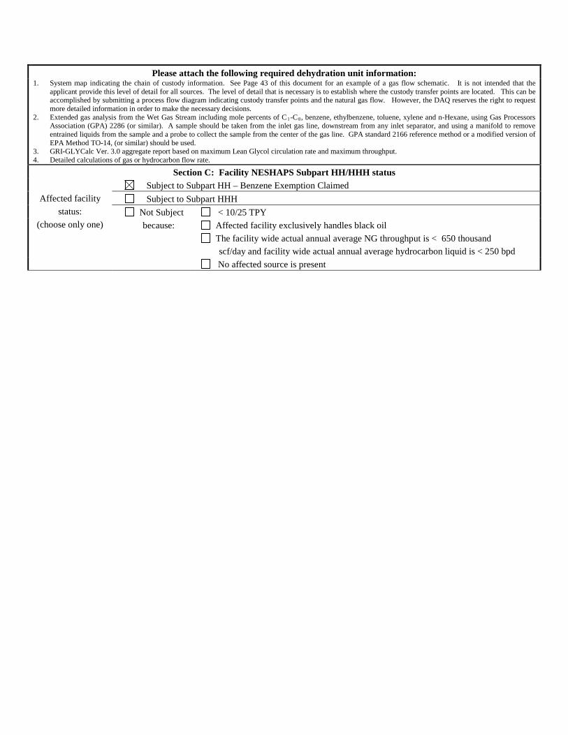
Please attach the following required dehydration unit information: 1. System map indicating the chain of custody information. See Page 43 of this document for an example of a gas flow schematic. It is not intended that the
applicant provide this level of detail for all sources. The level of detail that is necessary is to establish where the custody transfer points are located. This can be accomplished by submitting a process flow diagram indicating custody transfer points and the natural gas flow. However, the DAQ reserves the right to request more detailed information in order to make the necessary decisions.
2. Extended gas analysis from the Wet Gas Stream including mole percents of C1-C8, benzene, ethylbenzene, toluene, xylene and n-Hexane, using Gas Processors Association (GPA) 2286 (or similar). A sample should be taken from the inlet gas line, downstream from any inlet separator, and using a manifold to remove entrained liquids from the sample and a probe to collect the sample from the center of the gas line. GPA standard 2166 reference method or a modified version of EPA Method TO-14, (or similar) should be used.
3. GRI-GLYCalc Ver. 3.0 aggregate report based on maximum Lean Glycol circulation rate and maximum throughput. 4. Detailed calculations of gas or hydrocarbon flow rate.
Section C: Facility NESHAPS Subpart HH/HHH status
Affected facility status:
(choose only one)
Subject to Subpart HH – Benzene Exemption Claimed Subject to Subpart HHH Not Subject because:
< 10/25 TPY Affected facility exclusively handles black oil The facility wide actual annual average NG throughput is < 650 thousand
scf/day and facility wide actual annual average hydrocarbon liquid is < 250 bpd No affected source is present
Attachment M AIR POLLUTION CONTROL DEVICE SHEETS

AIR POLLUTION CONTROL DEVICE Vapor Combustion Control Device Sheet
Complete this vapor combustion control device sheet for each enclosed combustion device, flare, thermal oxidizer,
or completion combustion device that is located at the natural gas production pad for the purpose of thermally destructing waste gas to control emissions of regulated pollutants to the atmosphere.
IMPORTANT: READ THE INSTRUCTIONS ACCOMPANYING THIS FORM BEFORE COMPLETING.
General Information
1. Control Device ID#: DEHY1 2. Installation Date: 2015 New
3. Maximum Rated Total Flow Capacity: 50,000 scf/d
4. Maximum Design Heat Input: 2 MMBtu/hr
5. Design Heat Content: 588.3 Btu/scf
Control Device Information 6. Select the type of vapor combustion control device being used: Enclosed Combustion Device
Elevated Flare Ground Flare Thermal Oxidizer Completion Combustion Device
7. Manufacturer: Questor Technologies Inc. Model No.: Q50
8. Hours of operation per year: 8,760
9. List the emission units whose emissions are controlled by this vapor combustion control device: Emission Units: 004-02, DEHY1
10. Emission Unit ID# Emission Source Description: Emission Unit ID# Emission Source Description:
004-02 Dehydration Unit Still DEHY1 Enclosed Combustion Device
If this vapor combustor controls emissions from more than six emission units, please attach additional pages.
11. Assist Type 12. Flare Height 13. Tip Diameter 14. Was the design
per §60.18?
Steam - Air - Pressure - Non -
~8 ft 20 in Yes No
Waste Gas Information
15. Maximum waste gas flow rate (scfm):
16. Heat value of waste gas stream (BTU/ft3)
17. Temperature of the emissions stream (°F)
18. Exit Velocity of the emissions stream (ft/s)
55,200 scf/d Variable 70
19. Provide an attachment with the characteristics of the waste gas stream to be burned.
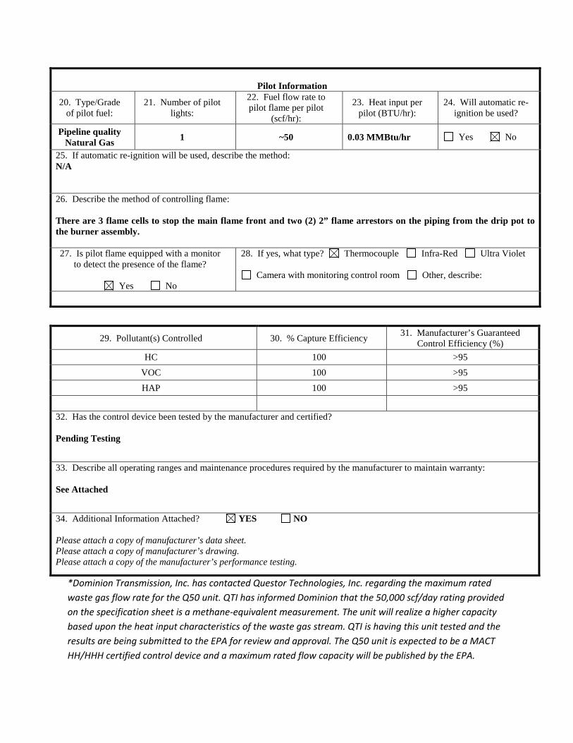
Pilot Information
20. Type/Grade of pilot fuel:
21. Number of pilot lights:
22. Fuel flow rate to pilot flame per pilot
(scf/hr):
23. Heat input per pilot (BTU/hr):
24. Will automatic re-ignition be used?
Pipeline quality Natural Gas 1 ~50 0.03 MMBtu/hr Yes No
25. If automatic re-ignition will be used, describe the method: N/A 26. Describe the method of controlling flame: There are 3 flame cells to stop the main flame front and two (2) 2” flame arrestors on the piping from the drip pot to the burner assembly. 27. Is pilot flame equipped with a monitor
to detect the presence of the flame?
Yes No
28. If yes, what type? Thermocouple Infra-Red Ultra Violet
Camera with monitoring control room Other, describe:
29. Pollutant(s) Controlled 30. % Capture Efficiency 31. Manufacturer’s Guaranteed Control Efficiency (%)
HC 100 >95
VOC 100 >95
HAP 100 >95
32. Has the control device been tested by the manufacturer and certified? Pending Testing
33. Describe all operating ranges and maintenance procedures required by the manufacturer to maintain warranty: See Attached
34. Additional Information Attached? YES NO Please attach a copy of manufacturer’s data sheet. Please attach a copy of manufacturer’s drawing. Please attach a copy of the manufacturer’s performance testing.
*Dominion Transmission, Inc. has contacted Questor Technologies, Inc. regarding the maximum rated waste gas flow rate for the Q50 unit. QTI has informed Dominion that the 50,000 scf/day rating provided on the specification sheet is a methane-equivalent measurement. The unit will realize a higher capacity based upon the heat input characteristics of the waste gas stream. QTI is having this unit tested and the results are being submitted to the EPA for review and approval. The Q50 unit is expected to be a MACT HH/HHH certified control device and a maximum rated flow capacity will be published by the EPA.

Questor Technology Inc. – Operations - 8515,109 Street, Grande Prairie, Alberta, Office 780-830-2797 Questor Technology Inc. – Head Office - 1121, 940 6th Ave, Calgary, Alberta, Office 403-571-1530
Incinerator Technical Data Sheet
QQ5500
For more information call (780) 830-2797 or (403) 571-1530
Or visit: www.questortech.com
Incinerator Technical Data Sheet:
QQ5500 Rev: 00
Page 1 of 7 Revision Number: 0
Release Date: 05/12/2013 Document Location: S:\1-Engineering\Incinerator Technical Datasheets\Q50\Q50 Technical Data Sheet.doc
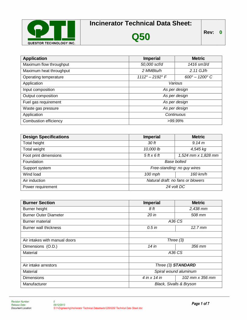
AApppplliiccaattiioonn IImmppeerriiaall MMeettrriicc
Maximum flow throughput 50,000 scf/d 1416 sm3/d
Maximum heat throughput 2 MMBtu/h 2.11 GJ/h
Operating temperature 1112° – 2192° F 600° – 1200° C
Application Various
Input composition As per design
Output composition As per design
Fuel gas requirement As per design
Waste gas pressure As per design
Application Continuous
Combustion efficiency >99.99%
DDeessiiggnn SSppeecciiffiiccaattiioonnss IImmppeerriiaall MMeettrriicc
Total height 30 ft 9.14 m
Total weight 10,000 lb 4,545 kg
Foot print dimensions 5 ft x 6 ft 1,524 mm x 1,828 mm
Foundation Base bolted
Support system Free-standing: no guy wires
Wind load 100 mph 160 km/h
Air induction Natural draft: no fans or blowers
Power requirement 24 volt DC
BBuurrnneerr SSeeccttiioonn IImmppeerriiaall MMeettrriicc
Burner height 8 ft 2,438 mm
Burner Outer Diameter 20 in 508 mm
Burner material A36 CS
Burner wall thickness 0.5 in 12.7 mm
Air intakes with manual doors Three (3)
Dimensions (O.D.) 14 in 356 mm
Material A36 CS
Air intake arrestors Three (3) STANDARD
Material Spiral wound aluminum
Dimensions 4 in x 14 in 102 mm x 356 mm
Manufacturer Black, Sivalls & Bryson
Incinerator Technical Data Sheet:
QQ5500 Rev: 00
Page 2 of 7 Revision Number: 0
Release Date: 05/12/2013 Document Location: S:\1-Engineering\Incinerator Technical Datasheets\Q50\Q50 Technical Data Sheet.doc
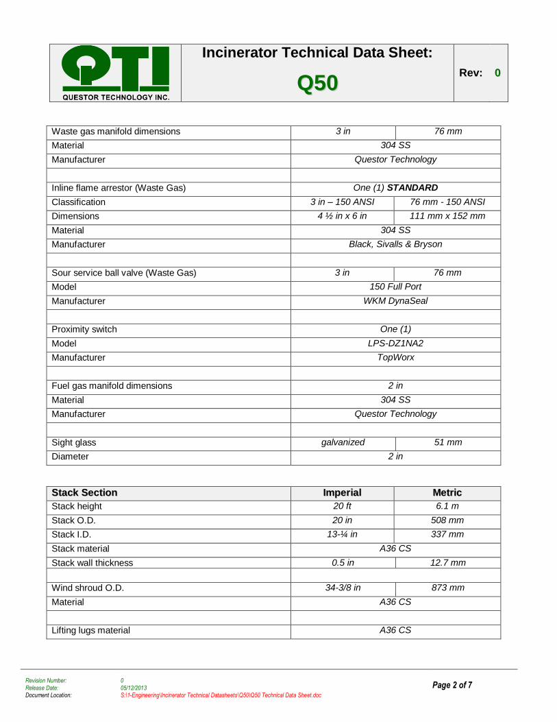
Waste gas manifold dimensions 3 in 76 mm
Material 304 SS
Manufacturer Questor Technology
Inline flame arrestor (Waste Gas) One (1) STANDARD
Classification 3 in – 150 ANSI 76 mm - 150 ANSI
Dimensions 4 ½ in x 6 in 111 mm x 152 mm
Material 304 SS
Manufacturer Black, Sivalls & Bryson
Sour service ball valve (Waste Gas) 3 in 76 mm
Model 150 Full Port
Manufacturer WKM DynaSeal
Proximity switch One (1)
Model LPS-DZ1NA2
Manufacturer TopWorx
Fuel gas manifold dimensions 2 in
Material 304 SS
Manufacturer Questor Technology
Sight glass galvanized 51 mm
Diameter 2 in
SSttaacckk SSeeccttiioonn IImmppeerriiaall MMeettrriicc
Stack height 20 ft 6.1 m
Stack O.D. 20 in 508 mm
Stack I.D. 13-¼ in 337 mm
Stack material A36 CS
Stack wall thickness 0.5 in 12.7 mm
Wind shroud O.D. 34-3/8 in 873 mm
Material A36 CS
Lifting lugs material A36 CS
Incinerator Technical Data Sheet:
QQ5500 Rev: 00
Page 3 of 7 Revision Number: 0
Release Date: 05/12/2013 Document Location: S:\1-Engineering\Incinerator Technical Datasheets\Q50\Q50 Technical Data Sheet.doc
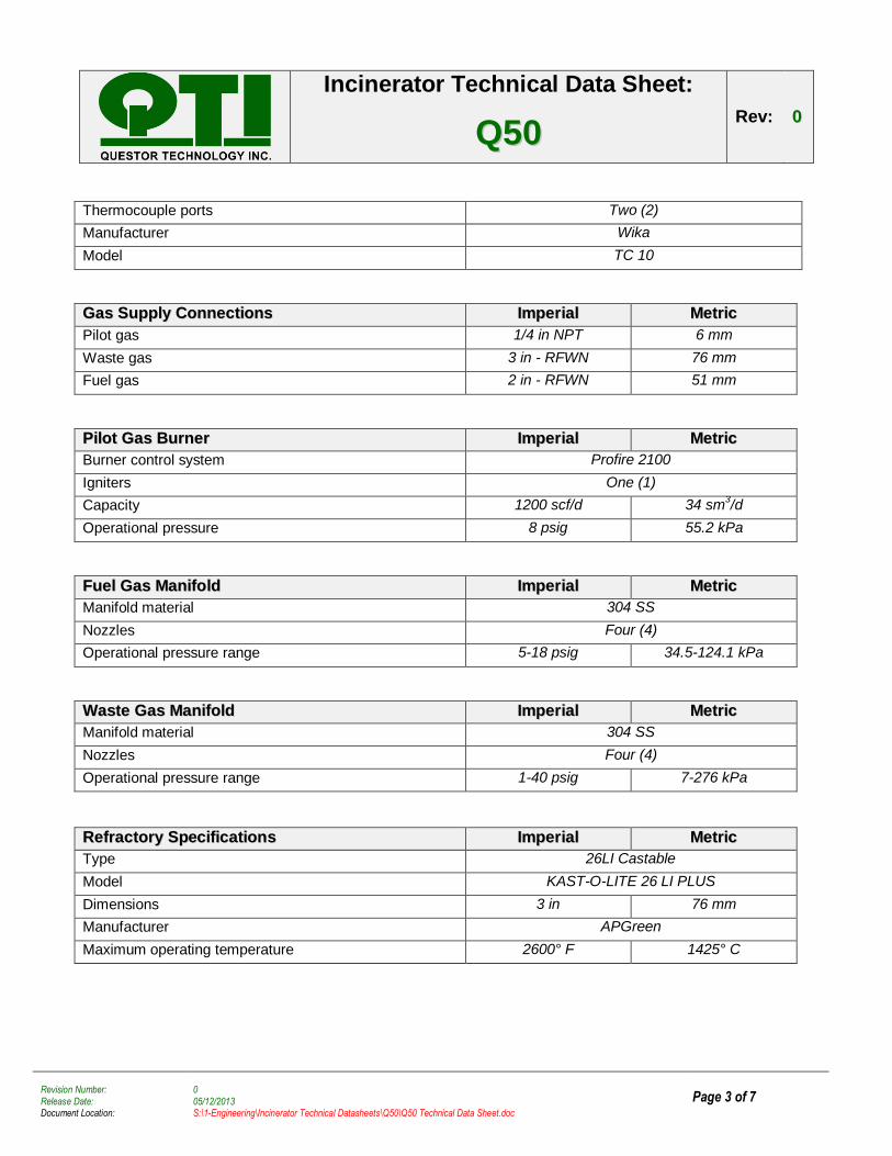
Thermocouple ports Two (2)
Manufacturer Wika
Model TC 10
GGaass SSuuppppllyy CCoonnnneeccttiioonnss IImmppeerriiaall MMeettrriicc
Pilot gas 1/4 in NPT 6 mm
Waste gas 3 in - RFWN 76 mm
Fuel gas 2 in - RFWN 51 mm
PPiilloott GGaass BBuurrnneerr IImmppeerriiaall MMeettrriicc
Burner control system Profire 2100
Igniters One (1)
Capacity 1200 scf/d 34 sm3/d
Operational pressure 8 psig 55.2 kPa
FFuueell GGaass MMaanniiffoolldd IImmppeerriiaall MMeettrriicc
Manifold material 304 SS
Nozzles Four (4)
Operational pressure range 5-18 psig 34.5-124.1 kPa
WWaassttee GGaass MMaanniiffoolldd IImmppeerriiaall MMeettrriicc
Manifold material 304 SS
Nozzles Four (4)
Operational pressure range 1-40 psig 7-276 kPa
RReeffrraaccttoorryy SSppeecciiffiiccaattiioonnss IImmppeerriiaall MMeettrriicc
Type 26LI Castable
Model KAST-O-LITE 26 LI PLUS
Dimensions 3 in 76 mm
Manufacturer APGreen
Maximum operating temperature 2600° F 1425° C
Incinerator Technical Data Sheet:
QQ5500 Rev: 00
Page 4 of 7 Revision Number: 0
Release Date: 05/12/2013 Document Location: S:\1-Engineering\Incinerator Technical Datasheets\Q50\Q50 Technical Data Sheet.doc
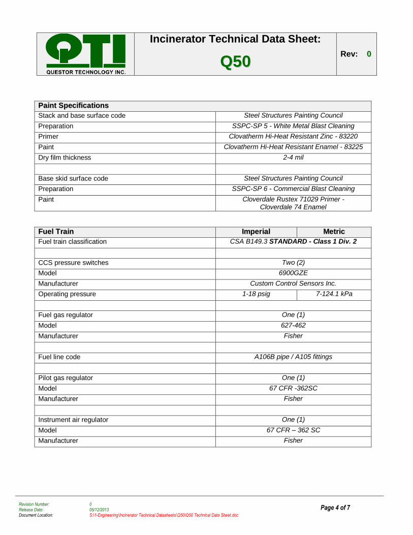
PPaaiinntt SSppeecciiffiiccaattiioonnss
Stack and base surface code Steel Structures Painting Council
Preparation SSPC-SP 5 - White Metal Blast Cleaning
Primer Clovatherm Hi-Heat Resistant Zinc - 83220
Paint Clovatherm Hi-Heat Resistant Enamel - 83225
Dry film thickness 2-4 mil
Base skid surface code Steel Structures Painting Council
Preparation SSPC-SP 6 - Commercial Blast Cleaning
Paint Cloverdale Rustex 71029 Primer - Cloverdale 74 Enamel
FFuueell TTrraaiinn IImmppeerriiaall MMeettrriicc
Fuel train classification CSA B149.3 STANDARD - Class 1 Div. 2
CCS pressure switches Two (2)
Model 6900GZE
Manufacturer Custom Control Sensors Inc.
Operating pressure 1-18 psig 7-124.1 kPa
Fuel gas regulator One (1)
Model 627-462
Manufacturer Fisher
Fuel line code A106B pipe / A105 fittings
Pilot gas regulator One (1)
Model 67 CFR -362SC
Manufacturer Fisher
Instrument air regulator One (1)
Model 67 CFR – 362 SC
Manufacturer Fisher
Incinerator Technical Data Sheet:
QQ5500 Rev: 00
Page 5 of 7 Revision Number: 0
Release Date: 05/12/2013 Document Location: S:\1-Engineering\Incinerator Technical Datasheets\Q50\Q50 Technical Data Sheet.doc
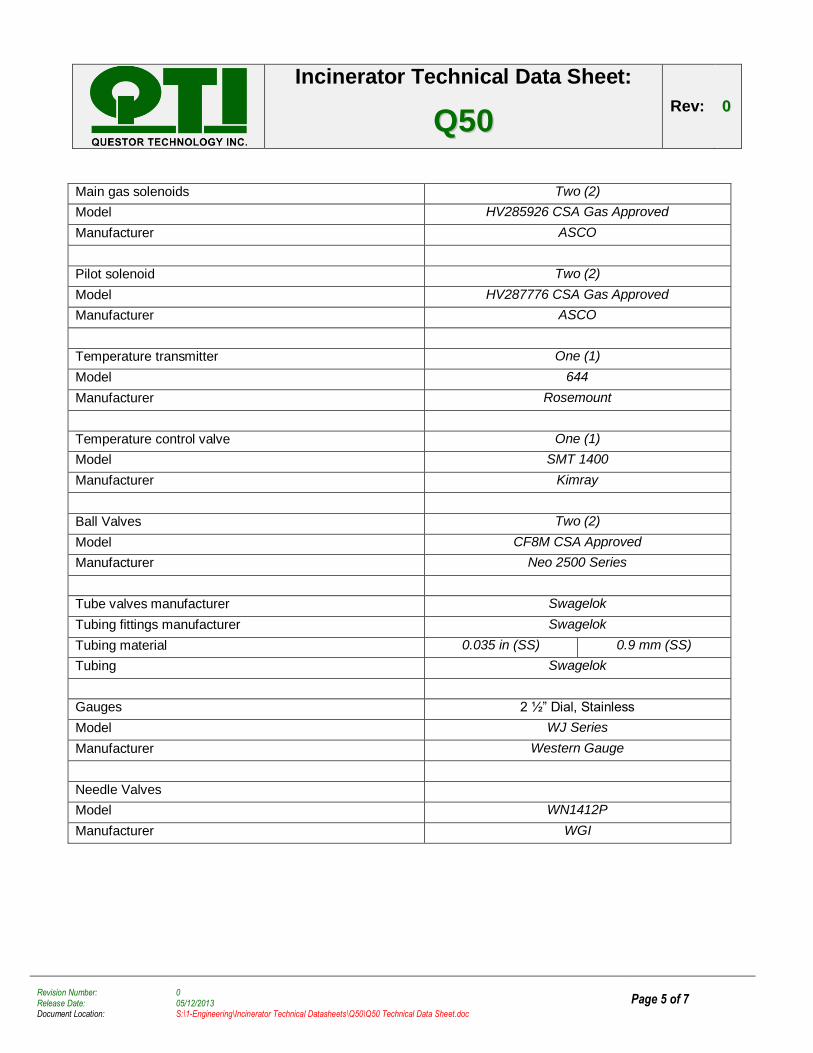
Main gas solenoids Two (2)
Model HV285926 CSA Gas Approved
Manufacturer ASCO
Pilot solenoid Two (2)
Model HV287776 CSA Gas Approved
Manufacturer ASCO
Temperature transmitter One (1)
Model 644
Manufacturer Rosemount
Temperature control valve One (1)
Model SMT 1400
Manufacturer Kimray
Ball Valves Two (2)
Model CF8M CSA Approved
Manufacturer Neo 2500 Series
Tube valves manufacturer Swagelok
Tubing fittings manufacturer Swagelok
Tubing material 0.035 in (SS) 0.9 mm (SS)
Tubing Swagelok
Gauges 2 ½” Dial, Stainless
Model WJ Series
Manufacturer Western Gauge
Needle Valves
Model WN1412P
Manufacturer WGI
Incinerator Technical Data Sheet:
QQ5500 Rev: 00
Page 6 of 7 Revision Number: 0
Release Date: 05/12/2013 Document Location: S:\1-Engineering\Incinerator Technical Datasheets\Q50\Q50 Technical Data Sheet.doc
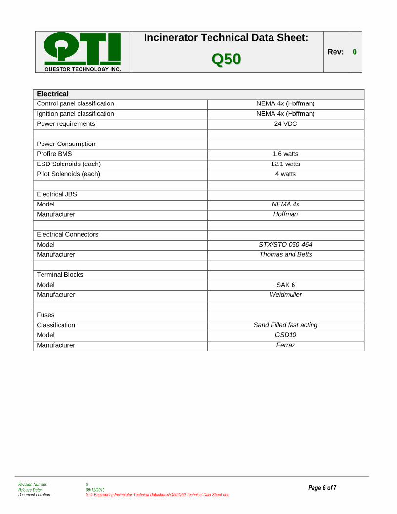
EElleeccttrriiccaall
Control panel classification NEMA 4x (Hoffman)
Ignition panel classification NEMA 4x (Hoffman)
Power requirements 24 VDC
Power Consumption
Profire BMS 1.6 watts
ESD Solenoids (each) 12.1 watts
Pilot Solenoids (each) 4 watts
Electrical JBS
Model NEMA 4x
Manufacturer Hoffman
Electrical Connectors
Model STX/STO 050-464
Manufacturer Thomas and Betts
Terminal Blocks
Model SAK 6
Manufacturer Weidmuller
Fuses
Classification Sand Filled fast acting
Model GSD10
Manufacturer Ferraz
Incinerator Technical Data Sheet:
QQ5500 Rev: 00
Page 7 of 7 Revision Number: 0
Release Date: 05/12/2013 Document Location: S:\1-Engineering\Incinerator Technical Datasheets\Q50\Q50 Technical Data Sheet.doc
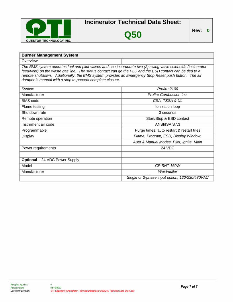
BBuurrnneerr MMaannaaggeemmeenntt SSyysstteemm
Overview
The BMS system operates fuel and pilot valves and can incorporate two (2) swing valve solenoids (incinerator feed/vent) on the waste gas line. The status contact can go the PLC and the ESD contact can be tied to a remote shutdown. Additionally, the BMS system provides an Emergency Stop Reset push button. The air damper is manual with a stop to prevent complete closure.
System Profire 2100
Manufacturer Profire Combustion Inc.
BMS code CSA, TSSA & UL
Flame testing Ionization loop
Shutdown rate 3 seconds
Remote operation Start/Stop & ESD contact
Instrument air code ANSI/ISA S7.3
Programmable Purge times, auto restart & restart tries
Display Flame, Program, ESD, Display Window,
Auto & Manual Modes, Pilot, Ignite, Main
Power requirements 24 VDC
Optional – 24 VDC Power Supply
Model CP SNT 160W
Manufacturer Weidmuller
Single or 3-phase input option, 120/230/480VAC
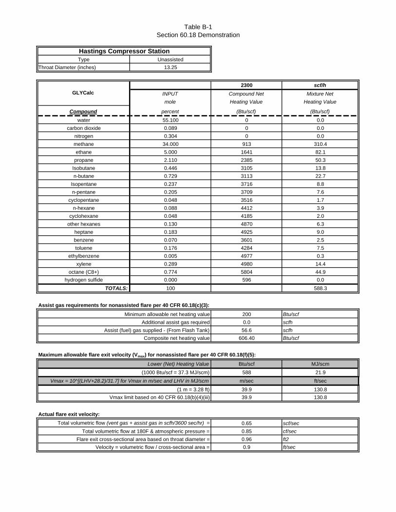
Table B-1Section 60.18 Demonstration
Type UnassistedThroat Diameter (inches) 13.25
2300 scf/h
INPUT Compound Net Mixture Net
mole Heating Value Heating Value
Compound percent (Btu/scf) (Btu/scf)
water 55.100 0 0.0carbon dioxide 0.089 0 0.0
nitrogen 0.304 0 0.0methane 34.000 913 310.4ethane 5.000 1641 82.1
propane 2.110 2385 50.3Isobutane 0.446 3105 13.8n-butane 0.729 3113 22.7
Isopentane 0.237 3716 8.8n-pentane 0.205 3709 7.6
cyclopentane 0.048 3516 1.7n-hexane 0.088 4412 3.9
cyclohexane 0.048 4185 2.0other hexanes 0.130 4870 6.3
heptane 0.183 4925 9.0benzene 0.070 3601 2.5toluene 0.176 4284 7.5
ethylbenzene 0.005 4977 0.3xylene 0.289 4980 14.4
octane (C8+) 0.774 5804 44.9hydrogen sulfide 0.000 596 0.0
TOTALS: 100 588.3
Assist gas requirements for nonassisted flare per 40 CFR 60.18(c)(3):
Minimum allowable net heating value 200 Btu/scf
Additional assist gas required 0.0 scfh
Assist (fuel) gas supplied - (From Flash Tank) 56.6 scfh
Composite net heating value 606.40 Btu/scf
Maximum allowable flare exit velocity (Vmax) for nonassisted flare per 40 CFR 60.18(f)(5):
Lower (Net) Heating Value Btu/scf MJ/scm(1000 Btu/scf = 37.3 MJ/scm) 588 21.9
Vmax = 10^[(LHV+28.2)/31.7] for Vmax in m/sec and LHV in MJ/scm m/sec ft/sec(1 m = 3.28 ft) 39.9 130.8
Vmax limit based on 40 CFR 60.18(b)(4)(iii) 39.9 130.8
Actual flare exit velocity:Total volumetric flow (vent gas + assist gas in scfh/3600 sec/hr) = 0.65 scf/sec
Total volumetric flow at 180F & atmospheric pressure = 0.85 cf/sec
Flare exit cross-sectional area based on throat diameter = 0.96 ft2
Velocity = volumetric flow / cross-sectional area = 0.9 ft/sec
Hastings Compressor Station
GLYCalc
Attachment N SUPPORTING EMISSIONS CALCULATIONS
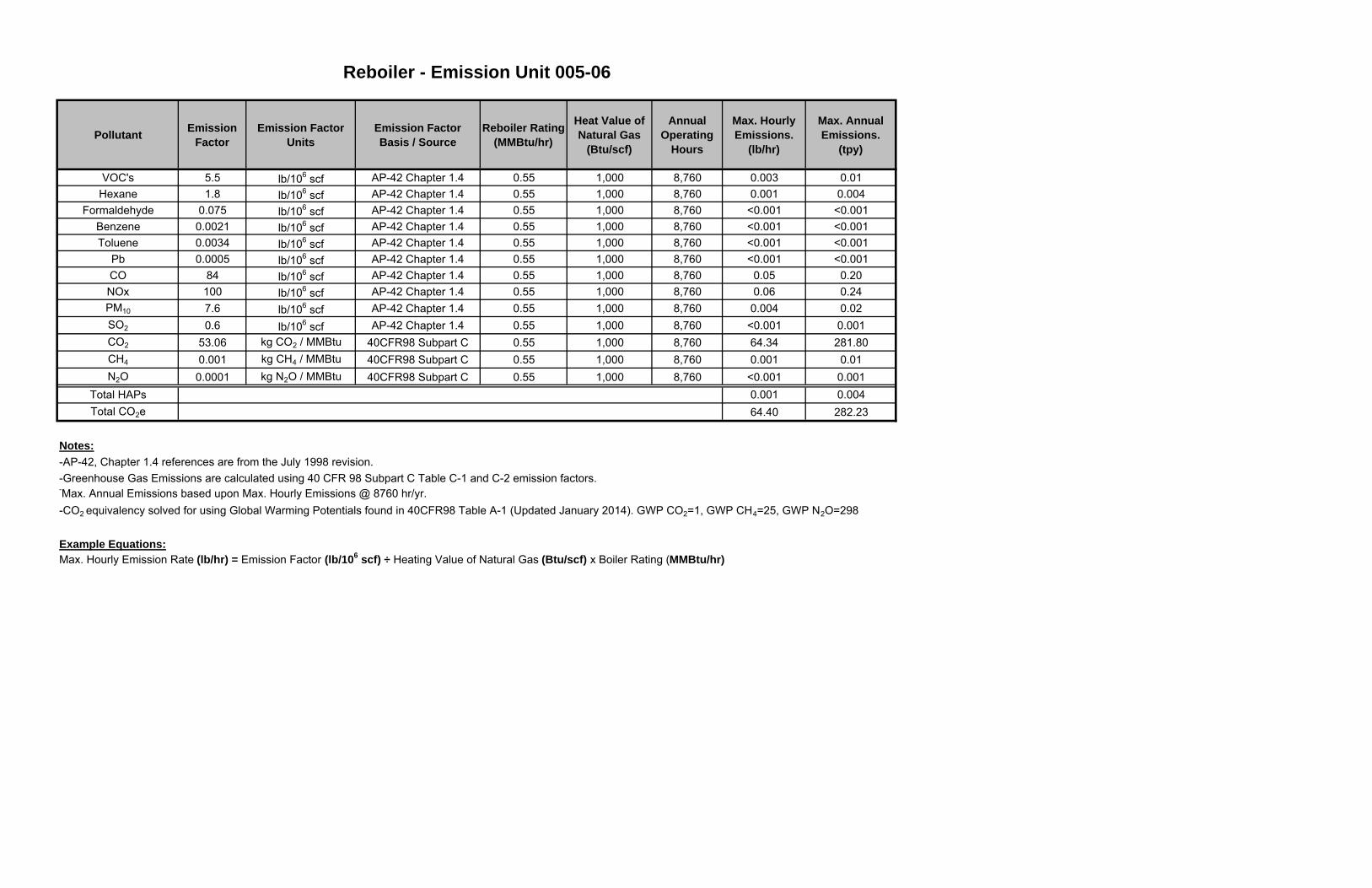
Pollutant Emission Factor
Emission FactorUnits
Emission FactorBasis / Source
Reboiler Rating (MMBtu/hr)
Heat Value of Natural Gas
(Btu/scf)
Annual Operating
Hours
Max. Hourly Emissions.
(lb/hr)
Max. Annual Emissions.
(tpy)
VOC's 5.5 lb/106 scf AP-42 Chapter 1.4 0.55 1,000 8,760 0.003 0.01Hexane 1.8 lb/106 scf AP-42 Chapter 1.4 0.55 1,000 8,760 0.001 0.004
Formaldehyde 0.075 lb/106 scf AP-42 Chapter 1.4 0.55 1,000 8,760 <0.001 <0.001Benzene 0.0021 lb/106 scf AP-42 Chapter 1.4 0.55 1,000 8,760 <0.001 <0.001Toluene 0.0034 lb/106 scf AP-42 Chapter 1.4 0.55 1,000 8,760 <0.001 <0.001
Pb 0.0005 lb/106 scf AP-42 Chapter 1.4 0.55 1,000 8,760 <0.001 <0.001CO 84 lb/106 scf AP-42 Chapter 1.4 0.55 1,000 8,760 0.05 0.20NOx 100 lb/106 scf AP-42 Chapter 1.4 0.55 1,000 8,760 0.06 0.24PM10 7.6 lb/106 scf AP-42 Chapter 1.4 0.55 1,000 8,760 0.004 0.02SO2 0.6 lb/106 scf AP-42 Chapter 1.4 0.55 1,000 8,760 <0.001 0.001CO2 53.06 kg CO2 / MMBtu 40CFR98 Subpart C 0.55 1,000 8,760 64.34 281.80CH4 0.001 kg CH4 / MMBtu 40CFR98 Subpart C 0.55 1,000 8,760 0.001 0.01N2O 0.0001 kg N2O / MMBtu 40CFR98 Subpart C 0.55 1,000 8,760 <0.001 0.001
Total HAPs 0.001 0.004Total CO2e 64.40 282.23
Notes:-AP-42, Chapter 1.4 references are from the July 1998 revision.
-Max. Annual Emissions based upon Max. Hourly Emissions @ 8760 hr/yr.-CO2 equivalency solved for using Global Warming Potentials found in 40CFR98 Table A-1 (Updated January 2014). GWP CO2=1, GWP CH4=25, GWP N2O=298
Example Equations:Max. Hourly Emission Rate (lb/hr) = Emission Factor (lb/106 scf) ÷ Heating Value of Natural Gas (Btu/scf) x Boiler Rating (MMBtu/hr)
-Greenhouse Gas Emissions are calculated using 40 CFR 98 Subpart C Table C-1 and C-2 emission factors.
Reboiler - Emission Unit 005-06
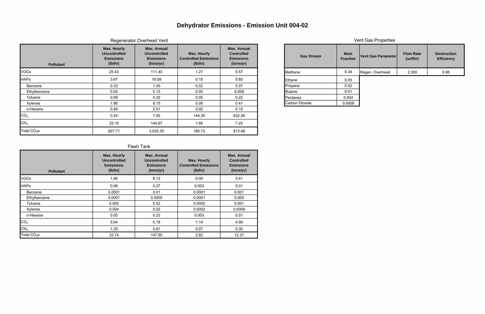
Pollutant
Max. Hourly Uncontrolled
Emissions(lb/hr)
Max. Annual Uncontrolled
Emissions(tons/yr)
Max. Hourly Controlled Emissions
(lb/hr)
Max. Annual Controlled Emissions(tons/yr)
Gas Stream Mole Fraction Vent Gas Parameter Flow Rate
(scf/hr)Destruction Efficiency
VOCs 25.43 111.40 1.27 5.57 Methane 0.34 Regen. Overhead 2,300 0.95
HAPs 3.67 16.08 0.18 0.80 Ethane 0.05Benzene 0.33 1.45 0.02 0.07 Propane 0.02Ethylbenzene 0.04 0.15 0.00 0.008 Butane 0.01Toluene 0.99 4.32 0.05 0.22 Pentanes 0.004Xylenes 1.86 8.15 0.09 0.41 Carbon Dioxide 0.0008n-Hexane 0.46 2.01 0.02 0.10
CO2 0.24 1.05 144.35 632.26
CH4 33.10 144.97 1.66 7.25
Total CO2e 827.71 3,625.30 185.73 813.48
Pollutant
Max. Hourly Uncontrolled
Emissions(lb/hr)
Max. Annual Uncontrolled
Emissions(tons/yr)
Max. Hourly Controlled Emissions
(lb/hr)
Max. Annual Controlled Emissions(tons/yr)
VOCs 1.86 8.13 0.09 0.41
HAPs 0.06 0.27 0.003 0.01Benzene 0.0001 0.01 0.0001 0.001Ethylbenzene 0.0001 0.0005 0.0001 0.000Toluene 0.005 0.02 0.0002 0.001Xylenes 0.004 0.02 0.0002 0.0009n-Hexane 0.05 0.22 0.003 0.01
CO2 0.04 0.18 1.14 4.99
CH4 1.35 5.91 0.07 0.30Total CO2e 33.74 147.80 2.82 12.37
Flash Tank
Vent Gas Properties
Dehydrator Emissions - Emission Unit 004-02
Regenerator Overhead Vent
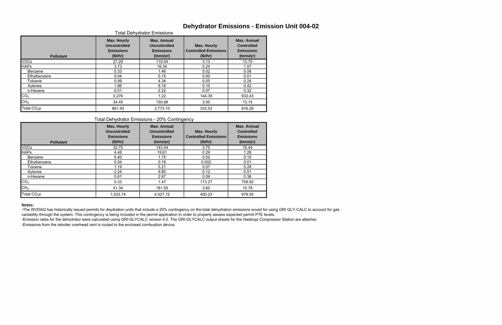
Pollutant
Max. Hourly Uncontrolled
Emissions(lb/hr)
Max. Annual Uncontrolled
Emissions(tons/yr)
Max. Hourly Controlled Emissions
(lb/hr)
Max. Annual Controlled Emissions(tons/yr)
VOCs 27.29 119.54 3.13 13.70HAPs 3.73 16.34 0.24 1.07
Benzene 0.33 1.46 0.02 0.08Ethylbenzene 0.04 0.15 0.00 0.01Toluene 0.99 4.34 0.05 0.24Xylenes 1.86 8.16 0.10 0.42n-Hexane 0.51 2.22 0.07 0.32
CO2 0.276 1.22 144.39 632.43CH4 34.45 150.88 3.00 13.15Total CO2e 861.45 3,773.10 333.53 816.29
Pollutant
Max. Hourly Uncontrolled
Emissions(lb/hr)
Max. Annual Uncontrolled
Emissions(tons/yr)
Max. Hourly Controlled Emissions
(lb/hr)
Max. Annual Controlled Emissions(tons/yr)
VOCs 32.75 143.44 3.75 16.44HAPs 4.48 19.61 0.29 1.28
Benzene 0.40 1.75 0.02 0.10Ethylbenzene 0.04 0.18 0.002 0.01Toluene 1.19 5.21 0.07 0.28Xylenes 2.24 9.80 0.12 0.51n-Hexane 0.61 2.67 0.09 0.38
CO2 0.33 1.47 173.27 758.92CH4 41.34 181.05 3.60 15.78Total CO2e 1,033.74 4,527.72 400.23 979.55
Notes:
-Emission rates for the dehydrator were calculated using GRI-GLYCALC version 4.0. The GRI-GLYCALC output sheets for the Hastings Compressor Station are attached-Emissions from the reboiler overhead vent is routed to the enclosed combustion device.
-The WVDAQ has historically issued permits for deydration units that include a 20% contingency on the total dehydration emissions soved for using GRI GLY-CALC to account for gas variability through the system. This contingency is being included in the permit application in order to properly assess expected permit PTE levels.
Dehydrator Emissions - Emission Unit 004-02Total Dehydrator Emissions
Total Dehydrator Emissions - 20% Contingency
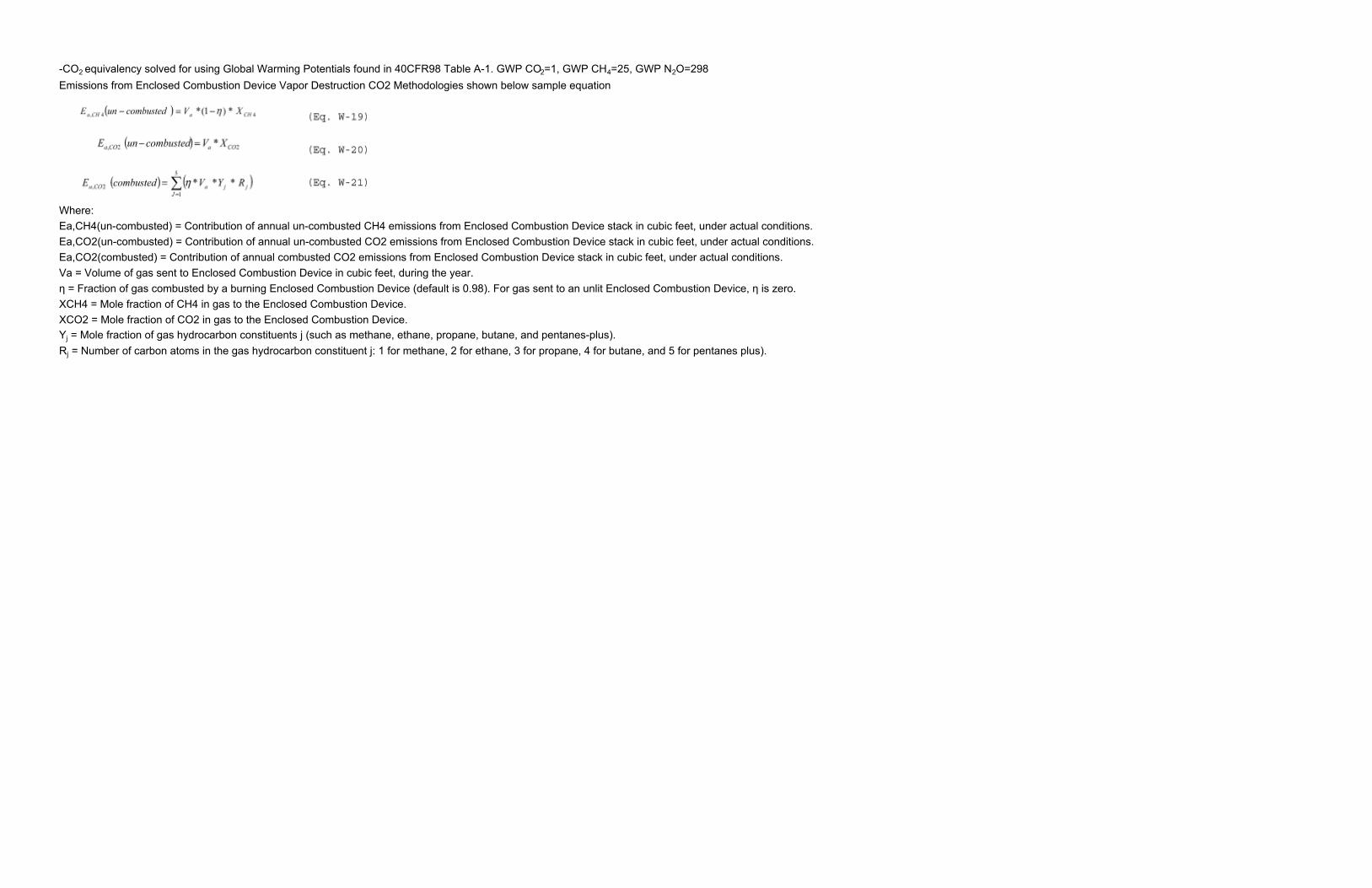
-CO2 equivalency solved for using Global Warming Potentials found in 40CFR98 Table A-1. GWP CO2=1, GWP CH4=25, GWP N2O=298Emissions from Enclosed Combustion Device Vapor Destruction CO2 Methodologies shown below sample equation
Where:Ea,CH4(un-combusted) = Contribution of annual un-combusted CH4 emissions from Enclosed Combustion Device stack in cubic feet, under actual conditions.Ea,CO2(un-combusted) = Contribution of annual un-combusted CO2 emissions from Enclosed Combustion Device stack in cubic feet, under actual conditions.Ea,CO2(combusted) = Contribution of annual combusted CO2 emissions from Enclosed Combustion Device stack in cubic feet, under actual conditions.Va = Volume of gas sent to Enclosed Combustion Device in cubic feet, during the year.η = Fraction of gas combusted by a burning Enclosed Combustion Device (default is 0.98). For gas sent to an unlit Enclosed Combustion Device, η is zero.XCH4 = Mole fraction of CH4 in gas to the Enclosed Combustion Device.XCO2 = Mole fraction of CO2 in gas to the Enclosed Combustion Device.Yj = Mole fraction of gas hydrocarbon constituents j (such as methane, ethane, propane, butane, and pentanes-plus).Rj = Number of carbon atoms in the gas hydrocarbon constituent j: 1 for methane, 2 for ethane, 3 for propane, 4 for butane, and 5 for pentanes plus).
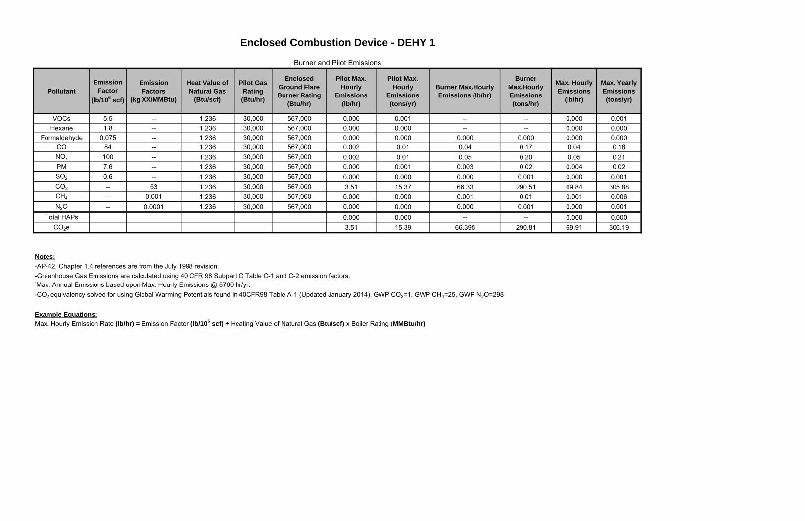
PollutantEmission
Factor(lb/106 scf)
Emission Factors
(kg XX/MMBtu)
Heat Value of Natural Gas
(Btu/scf)
Pilot Gas Rating(Btu/hr)
Enclosed Ground Flare Burner Rating
(Btu/hr)
Pilot Max. Hourly
Emissions(lb/hr)
Pilot Max. Hourly
Emissions(tons/yr)
Burner Max.Hourly Emissions (lb/hr)
Burner Max.Hourly Emissions (tons/hr)
Max. Hourly Emissions
(lb/hr)
Max. Yearly Emissions(tons/yr)
VOCs 5.5 -- 1,236 30,000 567,000 0.000 0.001 -- -- 0.000 0.001Hexane 1.8 -- 1,236 30,000 567,000 0.000 0.000 -- -- 0.000 0.000
Formaldehyde 0.075 -- 1,236 30,000 567,000 0.000 0.000 0.000 0.000 0.000 0.000CO 84 -- 1,236 30,000 567,000 0.002 0.01 0.04 0.17 0.04 0.18NOx 100 -- 1,236 30,000 567,000 0.002 0.01 0.05 0.20 0.05 0.21PM 7.6 -- 1,236 30,000 567,000 0.000 0.001 0.003 0.02 0.004 0.02SO2 0.6 -- 1,236 30,000 567,000 0.000 0.000 0.000 0.001 0.000 0.001CO2 -- 53 1,236 30,000 567,000 3.51 15.37 66.33 290.51 69.84 305.88CH4 -- 0.001 1,236 30,000 567,000 0.000 0.000 0.001 0.01 0.001 0.006N2O -- 0.0001 1,236 30,000 567,000 0.000 0.000 0.000 0.001 0.000 0.001
Total HAPs 0.000 0.000 -- -- 0.000 0.000CO2e 3.51 15.39 66.395 290.81 69.91 306.19
Notes:-AP-42, Chapter 1.4 references are from the July 1998 revision.
-Max. Annual Emissions based upon Max. Hourly Emissions @ 8760 hr/yr.-CO2 equivalency solved for using Global Warming Potentials found in 40CFR98 Table A-1 (Updated January 2014). GWP CO2=1, GWP CH4=25, GWP N2O=298
Example Equations:Max. Hourly Emission Rate (lb/hr) = Emission Factor (lb/106 scf) ÷ Heating Value of Natural Gas (Btu/scf) x Boiler Rating (MMBtu/hr)
Enclosed Combustion Device - DEHY 1
Burner and Pilot Emissions
-Greenhouse Gas Emissions are calculated using 40 CFR 98 Subpart C Table C-1 and C-2 emission factors.
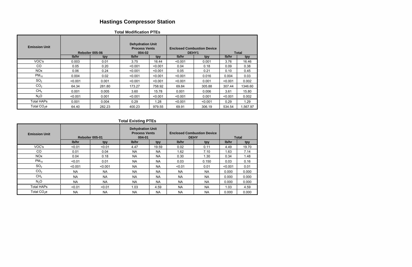
lb/hr tpy lb/hr tpy lb/hr tpy lb/hr tpyVOC's 0.003 0.01 3.75 16.44 <0.001 0.001 3.76 16.46
CO 0.05 0.20 <0.001 <0.001 0.04 0.18 0.09 0.38NOx 0.06 0.24 <0.001 <0.001 0.05 0.21 0.10 0.45PM10 0.004 0.02 <0.001 <0.001 <0.001 0.016 0.004 0.03SO2 <0.001 0.001 <0.001 <0.001 <0.001 0.001 <0.001 0.002CO2 64.34 281.80 173.27 758.92 69.84 305.88 307.44 1346.60CH4 0.001 0.005 3.60 15.78 0.001 0.006 3.61 15.80N2O <0.001 0.001 <0.001 <0.001 <0.001 0.001 <0.001 0.002
Total HAPs 0.001 0.004 0.29 1.28 <0.001 <0.001 0.29 1.29Total CO2e 64.40 282.23 400.23 979.55 69.91 306.19 534.54 1,567.97
lb/hr tpy lb/hr tpy lb/hr tpy lb/hr tpyVOC's <0.01 <0.01 4.47 19.59 0.02 0.11 4.49 19.70
CO 0.01 0.04 NA NA 1.62 7.10 1.63 7.14NOx 0.04 0.18 NA NA 0.30 1.30 0.34 1.48PM10 <0.01 0.01 NA NA 0.03 0.150 0.03 0.16SO2 <0.001 <0.001 NA NA <0.01 0.01 <0.001 0.01CO2 NA NA NA NA NA NA 0.000 0.000CH4 NA NA NA NA NA NA 0.000 0.000N2O NA NA NA NA NA NA 0.000 0.000
Total HAPs <0.01 <0.01 1.03 4.59 NA NA 1.03 4.59Total CO2e NA NA NA NA NA NA 0.000 0.000
Total Existing PTEs
Emission UnitReboiler 005-01
Dehydration UnitProcess Vents
004-01Enclosed Combustion Device
DEHY Total
Hastings Compressor Station
Total Modification PTEs
Reboiler 005-06
Dehydration UnitProcess Vents
004-02Enclosed Combustion Device
DEHY1 Total Emission Unit
lb/hr tpy lb/hr tpy lb/hr tpy lb/hr tpyVOC's -- 0.01 -0.72 -3.15 -0.02 -0.11 -0.73 -3.24
CO 0.04 0.16 -- -- -1.58 -6.92 -1.54 -6.76NOx 0.02 0.06 -- -- -0.25 -1.09 -0.24 -1.03PM10 -- 0.008 -- -- -0.03 -0.13 -0.03 -0.13SO2 -- -- -- -- -- -0.01 -- -0.008CO2 64.34 281.80 173.27 758.92 69.84 305.88 307.44 1,346.60CH4 0.001 0.005 3.60 15.78 0.001 0.006 3.606 15.796N2O <0.001 0.001 <0.001 <0.001 <0.001 0.001 <0.001 0.002
Total HAPs -- -- -0.74 -3.31 <0.001 <0.001 -0.74 -3.30Total CO2e 64.398 282.23 400.23 979.55 69.91 306.19 534.54 1,567.97
Proposed Change to PTEs
Emission UnitReboiler 005-06
Dehydration UnitProcess Vents
004-02Enclosed Combustion Device
DEHY1 Total
Hastings Compressor Station
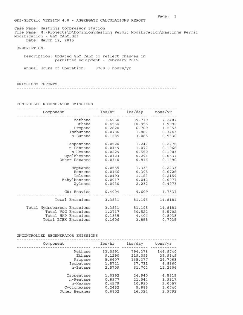
Page: 1GRI-GLYCalc VERSION 4.0 - AGGREGATE CALCULATIONS REPORT
Case Name: Hastings Compressor StationFile Name: M:\Projects\D\Dominion\Hasting Permit Modification\Hastings PermitModification - GLY CALC.ddf Date: March 12, 2015
DESCRIPTION:
Description: Updated GLY CALC to reflect changes in permitted equipment - February 2015
Annual Hours of Operation: 8760.0 hours/yr
EMISSIONS REPORTS: -------------------------------------------------------------------
CONTROLLED REGENERATOR EMISSIONS ------------------------------------------------------------------- Component lbs/hr lbs/day tons/yr ------------------------------- ----------- ----------- ----------- Methane 1.6550 39.719 7.2487 Ethane 0.4564 10.955 1.9992 Propane 0.2820 6.769 1.2353 Isobutane 0.0786 1.887 0.3443 n-Butane 0.1285 3.085 0.5630
Isopentane 0.0520 1.247 0.2276 n-Pentane 0.0449 1.077 0.1966 n-Hexane 0.0229 0.550 0.1003 Cyclohexane 0.0123 0.294 0.0537 Other Hexanes 0.0340 0.816 0.1490
Heptanes 0.0555 1.333 0.2433 Benzene 0.0166 0.398 0.0726 Toluene 0.0493 1.183 0.2159 Ethylbenzene 0.0017 0.042 0.0077 Xylenes 0.0930 2.232 0.4073
C8+ Heavies 0.4004 9.609 1.7537 ------------------------------- ----------- ----------- ----------- Total Emissions 3.3831 81.195 14.8181
Total Hydrocarbon Emissions 3.3831 81.195 14.8181 Total VOC Emissions 1.2717 30.522 5.5702 Total HAP Emissions 0.1835 4.404 0.8038 Total BTEX Emissions 0.1606 3.855 0.7035
UNCONTROLLED REGENERATOR EMISSIONS ------------------------------------------------------------------- Component lbs/hr lbs/day tons/yr ------------------------------- ----------- ----------- ----------- Methane 33.0991 794.378 144.9740 Ethane 9.1290 219.095 39.9849 Propane 5.6407 135.377 24.7063 Isobutane 1.5721 37.731 6.8860 n-Butane 2.5709 61.702 11.2606
Isopentane 1.0392 24.940 4.5515 n-Pentane 0.8977 21.544 3.9317 n-Hexane 0.4579 10.990 2.0057 Cyclohexane 0.2452 5.885 1.0740 Other Hexanes 0.6802 16.324 2.9792
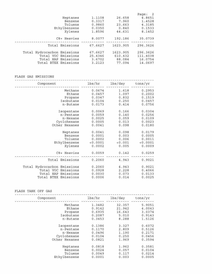
Page: 2 Heptanes 1.1108 26.658 4.8651 Benzene 0.3317 7.960 1.4528 Toluene 0.9860 23.663 4.3185 Ethylbenzene 0.0350 0.840 0.1533 Xylenes 1.8596 44.631 8.1452
C8+ Heavies 8.0077 192.186 35.0739 ------------------------------- ----------- ----------- ----------- Total Emissions 67.6627 1623.905 296.3626
Total Hydrocarbon Emissions 67.6627 1623.905 296.3626 Total VOC Emissions 25.4346 610.432 111.4038 Total HAP Emissions 3.6702 88.084 16.0754 Total BTEX Emissions 3.2123 77.094 14.0697
FLASH GAS EMISSIONS ------------------------------------------------------------------- Component lbs/hr lbs/day tons/yr ------------------------------- ----------- ----------- ----------- Methane 0.0674 1.618 0.2953 Ethane 0.0457 1.097 0.2002 Propane 0.0347 0.832 0.1519 Isobutane 0.0104 0.250 0.0457 n-Butane 0.0173 0.414 0.0756
Isopentane 0.0069 0.166 0.0304 n-Pentane 0.0059 0.140 0.0256 n-Hexane 0.0025 0.059 0.0109 Cyclohexane 0.0005 0.013 0.0023 Other Hexanes 0.0041 0.098 0.0180
Heptanes 0.0041 0.098 0.0179 Benzene 0.0001 0.003 0.0005 Toluene 0.0002 0.006 0.0011 Ethylbenzene <0.0001 <0.001 <0.0001 Xylenes 0.0002 0.005 0.0009
C8+ Heavies 0.0059 0.142 0.0259 ------------------------------- ----------- ----------- ----------- Total Emissions 0.2060 4.943 0.9021
Total Hydrocarbon Emissions 0.2060 4.943 0.9021 Total VOC Emissions 0.0928 2.228 0.4066 Total HAP Emissions 0.0030 0.073 0.0133 Total BTEX Emissions 0.0006 0.014 0.0025
FLASH TANK OFF GAS ------------------------------------------------------------------- Component lbs/hr lbs/day tons/yr ------------------------------- ----------- ----------- ----------- Methane 1.3482 32.357 5.9051 Ethane 0.9142 21.942 4.0043 Propane 0.6935 16.643 3.0374 Isobutane 0.2087 5.010 0.9143 n-Butane 0.3453 8.288 1.5126
Isopentane 0.1386 3.327 0.6072 n-Pentane 0.1170 2.809 0.5126 n-Hexane 0.0496 1.190 0.2171 Cyclohexane 0.0104 0.250 0.0456 Other Hexanes 0.0821 1.969 0.3594
Heptanes 0.0818 1.962 0.3581 Benzene 0.0024 0.057 0.0104 Toluene 0.0049 0.117 0.0214 Ethylbenzene 0.0001 0.003 0.0005
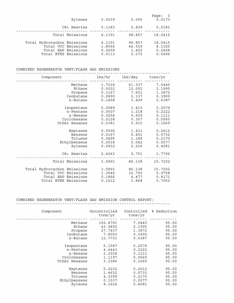
Page: 3 Xylenes 0.0039 0.095 0.0173
C8+ Heavies 0.1183 2.839 0.5181 ------------------------------- ----------- ----------- ----------- Total Emissions 4.1191 98.857 18.0415
Total Hydrocarbon Emissions 4.1191 98.857 18.0415 Total VOC Emissions 1.8566 44.559 8.1320 Total HAP Emissions 0.0609 1.462 0.2668 Total BTEX Emissions 0.0113 0.272 0.0496
COMBINED REGENERATOR VENT/FLASH GAS EMISSIONS ------------------------------------------------------------------- Component lbs/hr lbs/day tons/yr ------------------------------- ----------- ----------- ----------- Methane 1.7224 41.337 7.5440 Ethane 0.5022 12.052 2.1995 Propane 0.3167 7.601 1.3872 Isobutane 0.0890 2.137 0.3900 n-Butane 0.1458 3.499 0.6387
Isopentane 0.0589 1.413 0.2579 n-Pentane 0.0507 1.218 0.2222 n-Hexane 0.0254 0.609 0.1111 Cyclohexane 0.0128 0.307 0.0560 Other Hexanes 0.0381 0.915 0.1669
Heptanes 0.0596 1.431 0.2612 Benzene 0.0167 0.401 0.0732 Toluene 0.0495 1.189 0.2170 Ethylbenzene 0.0018 0.042 0.0077 Xylenes 0.0932 2.236 0.4081
C8+ Heavies 0.4063 9.751 1.7796 ------------------------------- ----------- ----------- ----------- Total Emissions 3.5891 86.138 15.7202
Total Hydrocarbon Emissions 3.5891 86.138 15.7202 Total VOC Emissions 1.3646 32.750 5.9768 Total HAP Emissions 0.1866 4.477 0.8171 Total BTEX Emissions 0.1612 3.868 0.7060
COMBINED REGENERATOR VENT/FLASH GAS EMISSION CONTROL REPORT: -------------------------------------------------------------------
Component Uncontrolled Controlled % Reduction tons/yr tons/yr ------------------------------- ------------ ------------ ------------ Methane 150.8791 7.5440 95.00 Ethane 43.9892 2.1995 95.00 Propane 27.7437 1.3872 95.00 Isobutane 7.8003 0.3900 95.00 n-Butane 12.7731 0.6387 95.00
Isopentane 5.1587 0.2579 95.00 n-Pentane 4.4443 0.2222 95.00 n-Hexane 2.2228 0.1111 95.00 Cyclohexane 1.1197 0.0560 95.00 Other Hexanes 3.3386 0.1669 95.00
Heptanes 5.2232 0.2612 95.00 Benzene 1.4632 0.0732 95.00 Toluene 4.3399 0.2170 95.00 Ethylbenzene 0.1537 0.0077 95.00 Xylenes 8.1624 0.4081 95.00
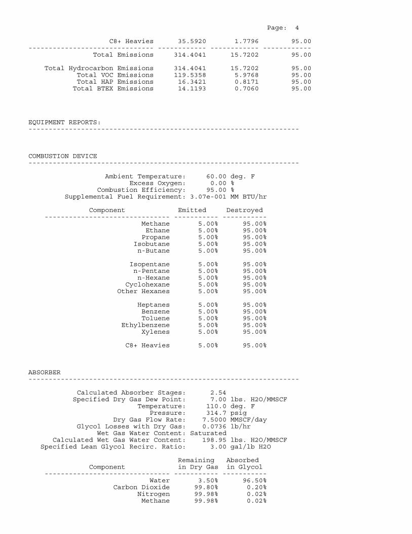
Page: 4
C8+ Heavies 35.5920 1.7796 95.00 ------------------------------- ------------ ------------ ------------ Total Emissions 314.4041 15.7202 95.00
Total Hydrocarbon Emissions 314.4041 15.7202 95.00 Total VOC Emissions 119.5358 5.9768 95.00 Total HAP Emissions 16.3421 0.8171 95.00 Total BTEX Emissions 14.1193 0.7060 95.00
EQUIPMENT REPORTS: -------------------------------------------------------------------
COMBUSTION DEVICE -------------------------------------------------------------------
Ambient Temperature: 60.00 deg. F Excess Oxygen: 0.00 % Combustion Efficiency: 95.00 % Supplemental Fuel Requirement: 3.07e-001 MM BTU/hr
Component Emitted Destroyed ------------------------------- ----------- ----------- Methane 5.00% 95.00% Ethane 5.00% 95.00% Propane 5.00% 95.00% Isobutane 5.00% 95.00% n-Butane 5.00% 95.00%
Isopentane 5.00% 95.00% n-Pentane 5.00% 95.00% n-Hexane 5.00% 95.00% Cyclohexane 5.00% 95.00% Other Hexanes 5.00% 95.00%
Heptanes 5.00% 95.00% Benzene 5.00% 95.00% Toluene 5.00% 95.00% Ethylbenzene 5.00% 95.00% Xylenes 5.00% 95.00%
C8+ Heavies 5.00% 95.00%
ABSORBER -------------------------------------------------------------------
Calculated Absorber Stages: 2.54 Specified Dry Gas Dew Point: 7.00 lbs. H2O/MMSCF Temperature: 110.0 deg. F Pressure: 314.7 psig Dry Gas Flow Rate: 7.5000 MMSCF/day Glycol Losses with Dry Gas: 0.0736 lb/hr Wet Gas Water Content: Saturated Calculated Wet Gas Water Content: 198.95 lbs. H2O/MMSCF Specified Lean Glycol Recirc. Ratio: 3.00 gal/lb H2O
Remaining Absorbed Component in Dry Gas in Glycol ------------------------------- ----------- ----------- Water 3.50% 96.50% Carbon Dioxide 99.80% 0.20% Nitrogen 99.98% 0.02% Methane 99.98% 0.02%
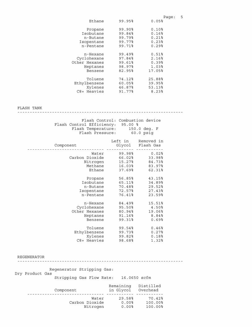
Page: 5 Ethane 99.95% 0.05%
Propane 99.90% 0.10% Isobutane 99.84% 0.16% n-Butane 99.79% 0.21% Isopentane 99.77% 0.23% n-Pentane 99.71% 0.29%
n-Hexane 99.49% 0.51% Cyclohexane 97.84% 2.16% Other Hexanes 99.61% 0.39% Heptanes 98.97% 1.03% Benzene 82.95% 17.05%
Toluene 74.12% 25.88% Ethylbenzene 60.05% 39.95% Xylenes 46.87% 53.13% C8+ Heavies 91.77% 8.23%
FLASH TANK -------------------------------------------------------------------
Flash Control: Combustion device Flash Control Efficiency: 95.00 % Flash Temperature: 150.0 deg. F Flash Pressure: 60.0 psig
Left in Removed in Component Glycol Flash Gas ------------------------------- ----------- ----------- Water 99.98% 0.02% Carbon Dioxide 66.02% 33.98% Nitrogen 15.27% 84.73% Methane 16.03% 83.97% Ethane 37.69% 62.31%
Propane 56.85% 43.15% Isobutane 65.11% 34.89% n-Butane 70.48% 29.52% Isopentane 72.57% 27.43% n-Pentane 76.41% 23.59%
n-Hexane 84.49% 15.51% Cyclohexane 95.50% 4.50% Other Hexanes 80.94% 19.06% Heptanes 91.16% 8.84% Benzene 99.31% 0.69%
Toluene 99.54% 0.46% Ethylbenzene 99.73% 0.27% Xylenes 99.82% 0.18% C8+ Heavies 98.68% 1.32%
REGENERATOR -------------------------------------------------------------------
Regenerator Stripping Gas: Dry Product Gas Stripping Gas Flow Rate: 16.0650 scfm
Remaining Distilled Component in Glycol Overhead ------------------------------- ----------- ----------- Water 29.58% 70.42% Carbon Dioxide 0.00% 100.00% Nitrogen 0.00% 100.00%
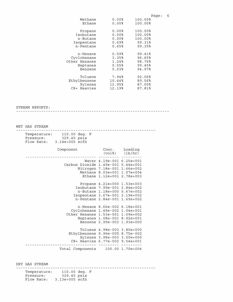
Page: 6 Methane 0.00% 100.00% Ethane 0.00% 100.00%
Propane 0.00% 100.00% Isobutane 0.00% 100.00% n-Butane 0.00% 100.00% Isopentane 0.69% 99.31% n-Pentane 0.65% 99.35%
n-Hexane 0.59% 99.41% Cyclohexane 3.35% 96.65% Other Hexanes 1.24% 98.76% Heptanes 0.55% 99.45% Benzene 5.03% 94.97%
Toluene 7.94% 92.06% Ethylbenzene 10.44% 89.56% Xylenes 12.95% 87.05% C8+ Heavies 12.19% 87.81%
STREAM REPORTS: -------------------------------------------------------------------
WET GAS STREAM ------------------------------------------------------------- Temperature: 110.00 deg. F Pressure: 329.40 psia Flow Rate: 3.14e+005 scfh
Component Conc. Loading (vol%) (lb/hr) ------------------------------- --------- --------- Water 4.19e-001 6.25e+001 Carbon Dioxide 1.49e-001 5.44e+001 Nitrogen 7.18e-001 1.66e+002 Methane 8.03e+001 1.07e+004 Ethane 1.12e+001 2.78e+003
Propane 4.21e+000 1.53e+003 Isobutane 7.99e-001 3.84e+002 n-Butane 1.18e+000 5.67e+002 Isopentane 3.67e-001 2.19e+002 n-Pentane 2.84e-001 1.69e+002
n-Hexane 8.66e-002 6.18e+001 Cyclohexane 1.49e-002 1.04e+001 Other Hexanes 1.53e-001 1.09e+002 Heptanes 1.08e-001 8.92e+001 Benzene 2.99e-003 1.93e+000
Toluene 4.98e-003 3.80e+000 Ethylbenzene 9.96e-005 8.75e-002 Xylenes 3.98e-003 3.50e+000 C8+ Heavies 6.77e-002 9.54e+001 ------------------------------- --------- --------- Total Components 100.00 1.70e+004
DRY GAS STREAM ------------------------------------------------------------- Temperature: 110.00 deg. F Pressure: 329.40 psia Flow Rate: 3.13e+005 scfh
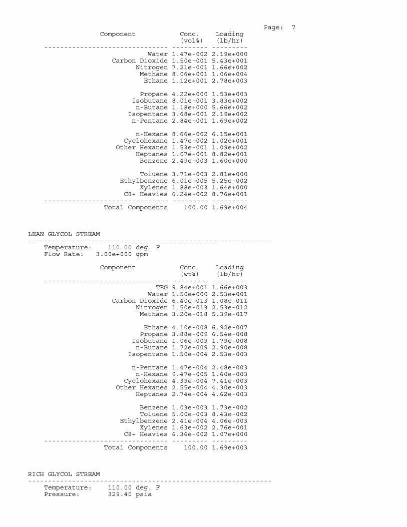
Page: 7 Component Conc. Loading (vol%) (lb/hr) ------------------------------- --------- --------- Water 1.47e-002 2.19e+000 Carbon Dioxide 1.50e-001 5.43e+001 Nitrogen 7.21e-001 1.66e+002 Methane 8.06e+001 1.06e+004 Ethane 1.12e+001 2.78e+003
Propane 4.22e+000 1.53e+003 Isobutane 8.01e-001 3.83e+002 n-Butane 1.18e+000 5.66e+002 Isopentane 3.68e-001 2.19e+002 n-Pentane 2.84e-001 1.69e+002
n-Hexane 8.66e-002 6.15e+001 Cyclohexane 1.47e-002 1.02e+001 Other Hexanes 1.53e-001 1.09e+002 Heptanes 1.07e-001 8.82e+001 Benzene 2.49e-003 1.60e+000
Toluene 3.71e-003 2.81e+000 Ethylbenzene 6.01e-005 5.25e-002 Xylenes 1.88e-003 1.64e+000 C8+ Heavies 6.24e-002 8.76e+001 ------------------------------- --------- --------- Total Components 100.00 1.69e+004
LEAN GLYCOL STREAM ------------------------------------------------------------- Temperature: 110.00 deg. F Flow Rate: 3.00e+000 gpm
Component Conc. Loading (wt%) (lb/hr) ------------------------------- --------- --------- TEG 9.84e+001 1.66e+003 Water 1.50e+000 2.53e+001 Carbon Dioxide 6.40e-013 1.08e-011 Nitrogen 1.50e-013 2.53e-012 Methane 3.20e-018 5.39e-017
Ethane 4.10e-008 6.92e-007 Propane 3.88e-009 6.54e-008 Isobutane 1.06e-009 1.79e-008 n-Butane 1.72e-009 2.90e-008 Isopentane 1.50e-004 2.53e-003
n-Pentane 1.47e-004 2.48e-003 n-Hexane 9.47e-005 1.60e-003 Cyclohexane 4.39e-004 7.41e-003 Other Hexanes 2.55e-004 4.30e-003 Heptanes 2.74e-004 4.62e-003
Benzene 1.03e-003 1.73e-002 Toluene 5.00e-003 8.43e-002 Ethylbenzene 2.41e-004 4.06e-003 Xylenes 1.63e-002 2.76e-001 C8+ Heavies 6.36e-002 1.07e+000 ------------------------------- --------- --------- Total Components 100.00 1.69e+003
RICH GLYCOL STREAM ------------------------------------------------------------- Temperature: 110.00 deg. F Pressure: 329.40 psia
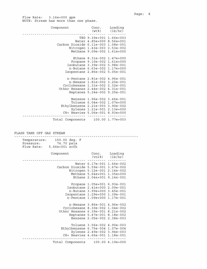
Page: 8 Flow Rate: 3.16e+000 gpm NOTE: Stream has more than one phase.
Component Conc. Loading (wt%) (lb/hr) ------------------------------- --------- --------- TEG 9.39e+001 1.66e+003 Water 4.85e+000 8.56e+001 Carbon Dioxide 6.11e-003 1.08e-001 Nitrogen 1.43e-003 2.53e-002 Methane 9.09e-002 1.61e+000
Ethane 8.31e-002 1.47e+000 Propane 9.10e-002 1.61e+000 Isobutane 3.39e-002 5.98e-001 n-Butane 6.63e-002 1.17e+000 Isopentane 2.86e-002 5.05e-001
n-Pentane 2.81e-002 4.96e-001 n-Hexane 1.81e-002 3.20e-001 Cyclohexane 1.31e-002 2.32e-001 Other Hexanes 2.44e-002 4.31e-001 Heptanes 5.24e-002 9.25e-001
Benzene 1.96e-002 3.46e-001 Toluene 6.04e-002 1.07e+000 Ethylbenzene 2.21e-003 3.90e-002 Xylenes 1.21e-001 2.13e+000 C8+ Heavies 5.06e-001 8.93e+000 ------------------------------- --------- --------- Total Components 100.00 1.77e+003
FLASH TANK OFF GAS STREAM ------------------------------------------------------------- Temperature: 150.00 deg. F Pressure: 74.70 psia Flow Rate: 5.66e+001 scfh
Component Conc. Loading (vol%) (lb/hr) ------------------------------- --------- --------- Water 6.17e-001 1.66e-002 Carbon Dioxide 5.59e-001 3.67e-002 Nitrogen 5.12e-001 2.14e-002 Methane 5.64e+001 1.35e+000 Ethane 2.04e+001 9.14e-001
Propane 1.05e+001 6.93e-001 Isobutane 2.41e+000 2.09e-001 n-Butane 3.99e+000 3.45e-001 Isopentane 1.29e+000 1.39e-001 n-Pentane 1.09e+000 1.17e-001
n-Hexane 3.86e-001 4.96e-002 Cyclohexane 8.30e-002 1.04e-002 Other Hexanes 6.39e-001 8.21e-002 Heptanes 5.47e-001 8.18e-002 Benzene 2.05e-002 2.38e-003
Toluene 3.56e-002 4.90e-003 Ethylbenzene 6.75e-004 1.07e-004 Xylenes 2.49e-002 3.94e-003 C8+ Heavies 4.66e-001 1.18e-001 ------------------------------- --------- --------- Total Components 100.00 4.19e+000
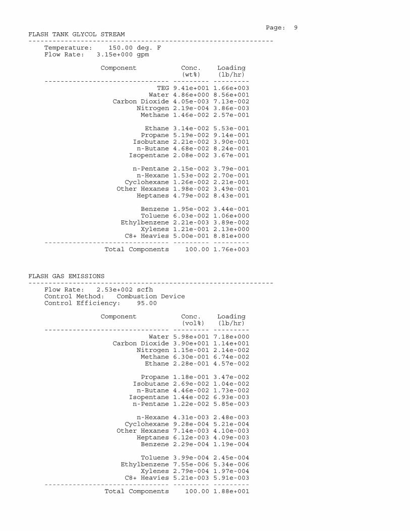
Page: 9 FLASH TANK GLYCOL STREAM ------------------------------------------------------------- Temperature: 150.00 deg. F Flow Rate: 3.15e+000 gpm
Component Conc. Loading (wt%) (lb/hr) ------------------------------- --------- --------- TEG 9.41e+001 1.66e+003 Water 4.86e+000 8.56e+001 Carbon Dioxide 4.05e-003 7.13e-002 Nitrogen 2.19e-004 3.86e-003 Methane 1.46e-002 2.57e-001
Ethane 3.14e-002 5.53e-001 Propane 5.19e-002 9.14e-001 Isobutane 2.21e-002 3.90e-001 n-Butane 4.68e-002 8.24e-001 Isopentane 2.08e-002 3.67e-001
n-Pentane 2.15e-002 3.79e-001 n-Hexane 1.53e-002 2.70e-001 Cyclohexane 1.26e-002 2.21e-001 Other Hexanes 1.98e-002 3.49e-001 Heptanes 4.79e-002 8.43e-001
Benzene 1.95e-002 3.44e-001 Toluene 6.03e-002 1.06e+000 Ethylbenzene 2.21e-003 3.89e-002 Xylenes 1.21e-001 2.13e+000 C8+ Heavies 5.00e-001 8.81e+000 ------------------------------- --------- --------- Total Components 100.00 1.76e+003
FLASH GAS EMISSIONS ------------------------------------------------------------- Flow Rate: 2.53e+002 scfh Control Method: Combustion Device Control Efficiency: 95.00
Component Conc. Loading (vol%) (lb/hr) ------------------------------- --------- --------- Water 5.98e+001 7.18e+000 Carbon Dioxide 3.90e+001 1.14e+001 Nitrogen 1.15e-001 2.14e-002 Methane 6.30e-001 6.74e-002 Ethane 2.28e-001 4.57e-002
Propane 1.18e-001 3.47e-002 Isobutane 2.69e-002 1.04e-002 n-Butane 4.46e-002 1.73e-002 Isopentane 1.44e-002 6.93e-003 n-Pentane 1.22e-002 5.85e-003
n-Hexane 4.31e-003 2.48e-003 Cyclohexane 9.28e-004 5.21e-004 Other Hexanes 7.14e-003 4.10e-003 Heptanes 6.12e-003 4.09e-003 Benzene 2.29e-004 1.19e-004
Toluene 3.99e-004 2.45e-004 Ethylbenzene 7.55e-006 5.34e-006 Xylenes 2.79e-004 1.97e-004 C8+ Heavies 5.21e-003 5.91e-003 ------------------------------- --------- --------- Total Components 100.00 1.88e+001
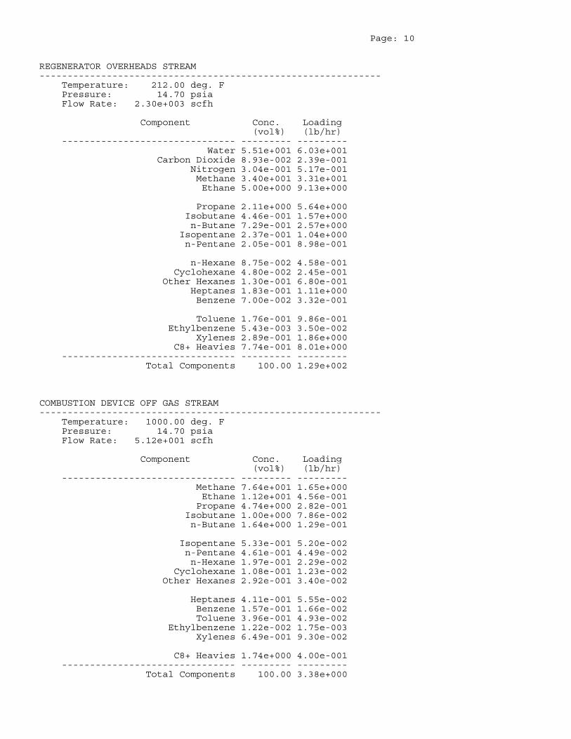
Page: 10
REGENERATOR OVERHEADS STREAM ------------------------------------------------------------- Temperature: 212.00 deg. F Pressure: 14.70 psia Flow Rate: 2.30e+003 scfh
Component Conc. Loading (vol%) (lb/hr) ------------------------------- --------- --------- Water 5.51e+001 6.03e+001 Carbon Dioxide 8.93e-002 2.39e-001 Nitrogen 3.04e-001 5.17e-001 Methane 3.40e+001 3.31e+001 Ethane 5.00e+000 9.13e+000
Propane 2.11e+000 5.64e+000 Isobutane 4.46e-001 1.57e+000 n-Butane 7.29e-001 2.57e+000 Isopentane 2.37e-001 1.04e+000 n-Pentane 2.05e-001 8.98e-001
n-Hexane 8.75e-002 4.58e-001 Cyclohexane 4.80e-002 2.45e-001 Other Hexanes 1.30e-001 6.80e-001 Heptanes 1.83e-001 1.11e+000 Benzene 7.00e-002 3.32e-001
Toluene 1.76e-001 9.86e-001 Ethylbenzene 5.43e-003 3.50e-002 Xylenes 2.89e-001 1.86e+000 C8+ Heavies 7.74e-001 8.01e+000 ------------------------------- --------- --------- Total Components 100.00 1.29e+002
COMBUSTION DEVICE OFF GAS STREAM ------------------------------------------------------------- Temperature: 1000.00 deg. F Pressure: 14.70 psia Flow Rate: 5.12e+001 scfh
Component Conc. Loading (vol%) (lb/hr) ------------------------------- --------- --------- Methane 7.64e+001 1.65e+000 Ethane 1.12e+001 4.56e-001 Propane 4.74e+000 2.82e-001 Isobutane 1.00e+000 7.86e-002 n-Butane 1.64e+000 1.29e-001
Isopentane 5.33e-001 5.20e-002 n-Pentane 4.61e-001 4.49e-002 n-Hexane 1.97e-001 2.29e-002 Cyclohexane 1.08e-001 1.23e-002 Other Hexanes 2.92e-001 3.40e-002
Heptanes 4.11e-001 5.55e-002 Benzene 1.57e-001 1.66e-002 Toluene 3.96e-001 4.93e-002 Ethylbenzene 1.22e-002 1.75e-003 Xylenes 6.49e-001 9.30e-002
C8+ Heavies 1.74e+000 4.00e-001 ------------------------------- --------- --------- Total Components 100.00 3.38e+000
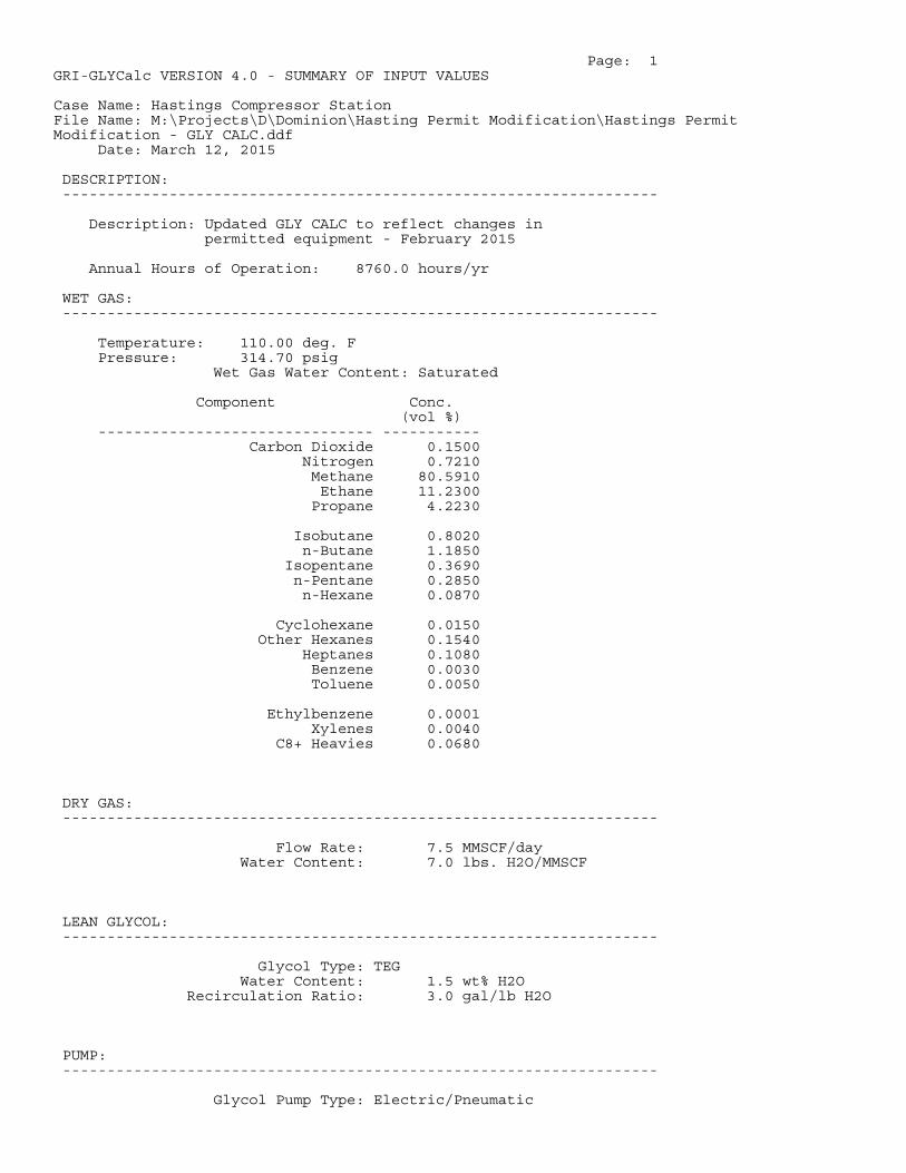
Page: 1GRI-GLYCalc VERSION 4.0 - SUMMARY OF INPUT VALUES
Case Name: Hastings Compressor StationFile Name: M:\Projects\D\Dominion\Hasting Permit Modification\Hastings PermitModification - GLY CALC.ddf Date: March 12, 2015
DESCRIPTION: -------------------------------------------------------------------
Description: Updated GLY CALC to reflect changes in permitted equipment - February 2015
Annual Hours of Operation: 8760.0 hours/yr
WET GAS: -------------------------------------------------------------------
Temperature: 110.00 deg. F Pressure: 314.70 psig Wet Gas Water Content: Saturated
Component Conc. (vol %) ------------------------------- ----------- Carbon Dioxide 0.1500 Nitrogen 0.7210 Methane 80.5910 Ethane 11.2300 Propane 4.2230
Isobutane 0.8020 n-Butane 1.1850 Isopentane 0.3690 n-Pentane 0.2850 n-Hexane 0.0870
Cyclohexane 0.0150 Other Hexanes 0.1540 Heptanes 0.1080 Benzene 0.0030 Toluene 0.0050
Ethylbenzene 0.0001 Xylenes 0.0040 C8+ Heavies 0.0680
DRY GAS: -------------------------------------------------------------------
Flow Rate: 7.5 MMSCF/day Water Content: 7.0 lbs. H2O/MMSCF
LEAN GLYCOL: -------------------------------------------------------------------
Glycol Type: TEG Water Content: 1.5 wt% H2O Recirculation Ratio: 3.0 gal/lb H2O
PUMP: -------------------------------------------------------------------
Glycol Pump Type: Electric/Pneumatic
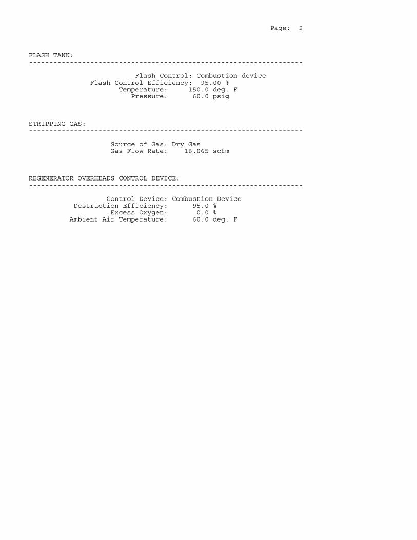
Page: 2
FLASH TANK: -------------------------------------------------------------------
Flash Control: Combustion device Flash Control Efficiency: 95.00 % Temperature: 150.0 deg. F Pressure: 60.0 psig
STRIPPING GAS: -------------------------------------------------------------------
Source of Gas: Dry Gas Gas Flow Rate: 16.065 scfm
REGENERATOR OVERHEADS CONTROL DEVICE: -------------------------------------------------------------------
Control Device: Combustion Device Destruction Efficiency: 95.0 % Excess Oxygen: 0.0 % Ambient Air Temperature: 60.0 deg. F
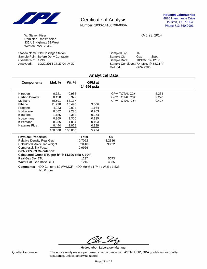
Houston Laboratories8820 Interchange Drive
Houston, TX 77054Phone 713-660-0901
Certificate of AnalysisNumber: 1030-14100796-006A
Oct. 23, 2014W. Steven KiserDominion Transmission335 US Highway 33 WestWeston , WV 26452
Station Name:Old Hastings Station Sampled By: TRSample Point: Before Dehy Contactor Sample Of: Gas SpotCylinder No: 1790 Sample Date: 10/13/2014 12:00Analyzed: 10/22/2014 13:33:04 by JD Sample Conditions:7.4 psig, @ 68.21 °F
Method: GPA 2286
Analytical Data
Components Mol. % Wt. % GPM at14.696 psia
Nitrogen 0.721 0.986Carbon Dioxide 0.150 0.322Methane 80.591 63.137Ethane 11.230 16.490 3.006Propane 4.223 9.094 1.164Iso-butane 0.802 2.276 0.263n-Butane 1.185 3.363 0.374Iso-pentane 0.369 1.300 0.135n-Pentane 0.285 1.004 0.103Hexanes Plus 0.444 2.028 0.189
100.000 100.000 5.234
GPM TOTAL C2+ 5.234GPM TOTAL C3+ 2.228GPM TOTAL iC5+ 0.427
Physical Properties Total C6+Relative Density Real Gas 0.7092 3.2186Calculated Molecular Weight 20.48 93.22Compressibility Factor 0.9966GPA 2172-09 Calculation:Calculated Gross BTU per ft³ @ 14.696 psia & 60°FReal Gas Dry BTU 1237 5073Water Sat. Gas Base BTU 1215 4985
Comments: H2O Content: 80 #/MMCF ; H2O Mol% : 1.744 ; Wt% : 1.538H2S 0 ppm
Hydrocarbon Laboratory Manager
Quality Assurance: The above analyses are performed in accordance with ASTM, UOP, GPA guidelines for qualityassurance, unless otherwise stated.
Page 21 of 25
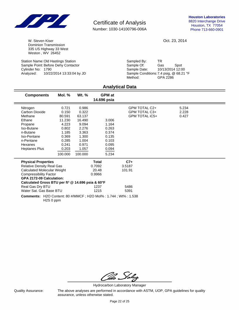
Houston Laboratories8820 Interchange Drive
Houston, TX 77054Phone 713-660-0901
Certificate of AnalysisNumber: 1030-14100796-006A
Oct. 23, 2014W. Steven KiserDominion Transmission335 US Highway 33 WestWeston , WV 26452
Station Name:Old Hastings Station Sampled By: TRSample Point: Before Dehy Contactor Sample Of: Gas SpotCylinder No: 1790 Sample Date: 10/13/2014 12:00Analyzed: 10/22/2014 13:33:04 by JD Sample Conditions:7.4 psig, @ 68.21 °F
Method: GPA 2286
Analytical Data
Components Mol. % Wt. % GPM at14.696 psia
Nitrogen 0.721 0.986Carbon Dioxide 0.150 0.322Methane 80.591 63.137Ethane 11.230 16.490 3.006Propane 4.223 9.094 1.164Iso-Butane 0.802 2.276 0.263n-Butane 1.185 3.363 0.374Iso-Pentane 0.369 1.300 0.135n-Pentane 0.285 1.004 0.103Hexanes 0.241 0.971 0.095Heptanes Plus 0.203 1.057 0.094
100.000 100.000 5.234
GPM TOTAL C2+ 5.234GPM TOTAL C3+ 2.228GPM TOTAL iC5+ 0.427
Physical Properties Total C7+Relative Density Real Gas 0.7092 3.5187Calculated Molecular Weight 20.48 101.91Compressibility Factor 0.9966GPA 2172-09 Calculation:Calculated Gross BTU per ft³ @ 14.696 psia & 60°FReal Gas Dry BTU 1237 5486Water Sat. Gas Base BTU 1215 5391
Comments: H2O Content: 80 #/MMCF ; H2O Mol% : 1.744 ; Wt% : 1.538H2S 0 ppm
Hydrocarbon Laboratory Manager
Quality Assurance: The above analyses are performed in accordance with ASTM, UOP, GPA guidelines for qualityassurance, unless otherwise stated.
Page 22 of 25
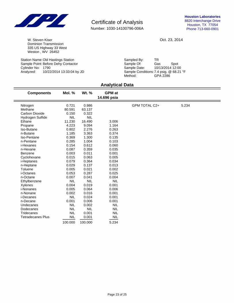
Houston Laboratories8820 Interchange Drive
Houston, TX 77054Phone 713-660-0901
Certificate of AnalysisNumber: 1030-14100796-006A
Oct. 23, 2014W. Steven KiserDominion Transmission335 US Highway 33 WestWeston , WV 26452
Station Name:Old Hastings Station Sampled By: TRSample Point: Before Dehy Contactor Sample Of: Gas SpotCylinder No: 1790 Sample Date: 10/13/2014 12:00Analyzed: 10/22/2014 13:33:04 by JD Sample Conditions:7.4 psig, @ 68.21 °F
Method: GPA 2286
Analytical Data
Components Mol. % Wt. % GPM at14.696 psia
Nitrogen 0.721 0.986Methane 80.591 63.137Carbon Dioxide 0.150 0.322Hydrogen Sulfide NIL NILEthane 11.230 16.490 3.006Propane 4.223 9.094 1.164Iso-Butane 0.802 2.276 0.263n-Butane 1.185 3.363 0.374Iso-Pentane 0.369 1.300 0.135n-Pentane 0.285 1.004 0.103i-Hexanes 0.154 0.612 0.060n-Hexane 0.087 0.359 0.035Benzene 0.003 0.011 0.001Cyclohexane 0.015 0.063 0.005i-Heptanes 0.079 0.364 0.034n-Heptane 0.029 0.137 0.013Toluene 0.005 0.021 0.002i-Octanes 0.053 0.287 0.025n-Octane 0.007 0.041 0.004Ethylbenzene NIL NIL NILXylenes 0.004 0.019 0.001i-Nonanes 0.005 0.064 0.006n-Nonane 0.002 0.016 0.001i-Decanes NIL 0.024 0.001n-Decane 0.001 0.006 0.001Undecanes NIL 0.002 NILDodecanes NIL NIL NILTridecanes NIL 0.001 NILTetradecanes Plus NIL 0.001 NIL
100.000 100.000 5.234
GPM TOTAL C2+ 5.234
Page 23 of 25
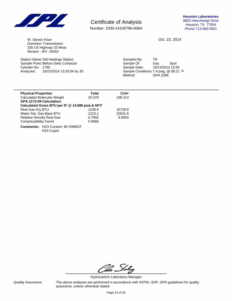
Houston Laboratories8820 Interchange Drive
Houston, TX 77054Phone 713-660-0901
Certificate of AnalysisNumber: 1030-14100796-006A
Oct. 23, 2014W. Steven KiserDominion Transmission335 US Highway 33 WestWeston , WV 26452
Station Name:Old Hastings Station Sampled By: TRSample Point: Before Dehy Contactor Sample Of: Gas SpotCylinder No: 1790 Sample Date: 10/13/2014 12:00Analyzed: 10/22/2014 13:33:04 by JD Sample Conditions:7.4 psig, @ 68.21 °F
Method: GPA 2286
Physical Properties Total C14+Calculated Molecular Weight 20.478 198.413GPA 2172-09 Calculation:Calculated Gross BTU per ft³ @ 14.696 psia & 60°FReal Gas Dry BTU 1236.6 10728.8Water Sat. Gas Base BTU 1215.1 10541.6Relative Density Real Gas 0.7092 6.8500Compressibility Factor 0.9966
Comments: H2O Content: 80 #/MMCFH2S 0 ppm
Hydrocarbon Laboratory Manager
Quality Assurance: The above analyses are performed in accordance with ASTM, UOP, GPA guidelines for qualityassurance, unless otherwise stated.
Page 24 of 25
Attachment O MONITORING, REPORTING, AND
RECORDKEEPING PLAN
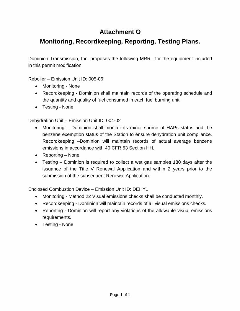
Page 1 of 1
Attachment O Monitoring, Recordkeeping, Reporting, Testing Plans.
Dominion Transmission, Inc. proposes the following MRRT for the equipment included in this permit modification: Reboiler – Emission Unit ID: 005-06
• Monitoring - None • Recordkeeping - Dominion shall maintain records of the operating schedule and
the quantity and quality of fuel consumed in each fuel burning unit. • Testing - None
Dehydration Unit – Emission Unit ID: 004-02
• Monitoring – Dominion shall monitor its minor source of HAPs status and the benzene exemption status of the Station to ensure dehydration unit compliance. Recordkeeping –Dominion will maintain records of actual average benzene emissions in accordance with 40 CFR 63 Section HH.
• Reporting – None • Testing – Dominion is required to collect a wet gas samples 180 days after the
issuance of the Title V Renewal Application and within 2 years prior to the submission of the subsequent Renewal Application.
Enclosed Combustion Device – Emission Unit ID: DEHY1
• Monitoring - Method 22 Visual emissions checks shall be conducted monthly. • Recordkeeping - Dominion will maintain records of all visual emissions checks. • Reporting - Dominion will report any violations of the allowable visual emissions
requirements. • Testing - None

Attachment P
PUBLIC NOTICE
AIR QUALITY PERMIT NOTICE
Notice of Application Notice is given that Dominion Transmission, Inc. has applied to the West Virginia Department of Environmental Protection, Division of Air Quality, for a Modification Permit for the Hastings Compressor Station, for a natural gas production operation, located in Pine Grove, Wetzel County, West Virginia. The latitude and longitude coordinates are: 39.54989 and -80.67244. Startup of operations is scheduled to begin on October 15, 2015. The applicant estimates the total increase in maximum potential to discharge the following regulated air pollutants on a facility-wide basis: 1,567.97 tpy of greenhouse gases, measured in CO2 equivalencies. All other pollutants decrease with this proposed project. Written comments will be received by the West Virginia Department of Environmental Protection, Division of Air Quality, 601 57th Street, SE, Charleston, WV 25304, for at least 30 calendar days from the date of publication of this notice. Any questions regarding this permit application should be directed to the DAQ at (304) 926-0499, extension 1227, during normal business hours. Dated this the XXth day of March, 2015. By: Dominion Transmission, Inc. Brian Sheppard Vice President of Pipeline Operations 445 West Main Street Clarksburg, WV 26301

Attachment S TITLE V PERMIT
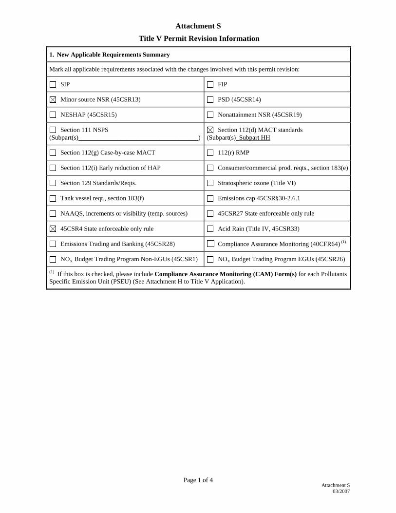
Attachment S
03/2007
Page 1 of 4
Attachment S
Title V Permit Revision Information
1. New Applicable Requirements Summary
Mark all applicable requirements associated with the changes involved with this permit revision:
SIP FIP
Minor source NSR (45CSR13) PSD (45CSR14)
NESHAP (45CSR15) Nonattainment NSR (45CSR19)
Section 111 NSPS (Subpart(s)_____________________________________)
Section 112(d) MACT standards (Subpart(s)_Subpart HH
Section 112(g) Case-by-case MACT 112(r) RMP
Section 112(i) Early reduction of HAP Consumer/commercial prod. reqts., section 183(e)
Section 129 Standards/Reqts. Stratospheric ozone (Title VI)
Tank vessel reqt., section 183(f) Emissions cap 45CSR§30-2.6.1
NAAQS, increments or visibility (temp. sources) 45CSR27 State enforceable only rule
45CSR4 State enforceable only rule Acid Rain (Title IV, 45CSR33)
Emissions Trading and Banking (45CSR28) Compliance Assurance Monitoring (40CFR64) (1)
NOx Budget Trading Program Non-EGUs (45CSR1) NOx Budget Trading Program EGUs (45CSR26)
(1) If this box is checked, please include Compliance Assurance Monitoring (CAM) Form(s) for each Pollutants Specific Emission Unit (PSEU) (See Attachment H to Title V Application).
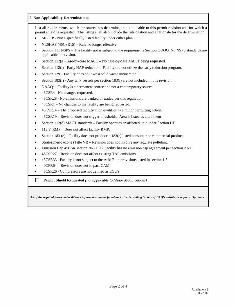
Attachment S
03/2007
Page 2 of 4
2. Non Applicability Determinations
List all requirements, which the source has determined not applicable to this permit revision and for which a permit shield is requested. The listing shall also include the rule citation and a rationale for the determination. • SIP/FIP - Not a specifically listed facility under either plan.
• NESHAP (45CSR15) – Rule no longer effective. • Section 111 NSPS – The facility not is subject to the requirements Section OOOO. No NSPS standards are
applicable to revision.
• Section 112(g) Case-by-case MACT – No case-by-case MACT being requested.
• Section 112(i) - Early HAP reduction - Facility did not utilize the early reduction program.
• Section 129 – Facility does not own a solid waste incinerator.
• Section 183(f) - Any tank vessels per section 183(f) are not included in this revision.
• NAAQs - Facility is a permanent source and not a contemporary source. • 45CSR4 - No changes requested. • 45CSR28 - No emissions are banked or traded per this regulation. • 45CSR1 – No changes to the facility are being requested. • 45CSR14 – The proposed modification qualifies as a minor permitting action.
• 45CSR19 – Revision does not trigger thresholds. Area is listed as attainment
• Section 112(d) MACT standards – Facility operates an affected unit under Section HH.
• 112(r) RMP – Does not affect facility RMP.
• Section 183 (e) - Facility does not produce a 183(e) listed consumer or commercial product.
• Stratospheric ozone (Title VI) – Revision does not involve any regulate pollutant. • Emission Cap 45CSR section 30-2.6.1 - Facility has no emission cap agreement per section 2.6.1. • 45CSR27 – Revision does not affect existing TAP emissions. • 45CSR33 - Facility is not subject to the Acid Rain provisions listed in section 1.5. • 40CFR64 – Revision does not impact CAM. • 45CSR26 - Compressors are not defined as EGU's.
Permit Shield Requested (not applicable to Minor Modifications)
All of the required forms and additional information can be found under the Permitting Section of DAQ’s website, or requested by phone.
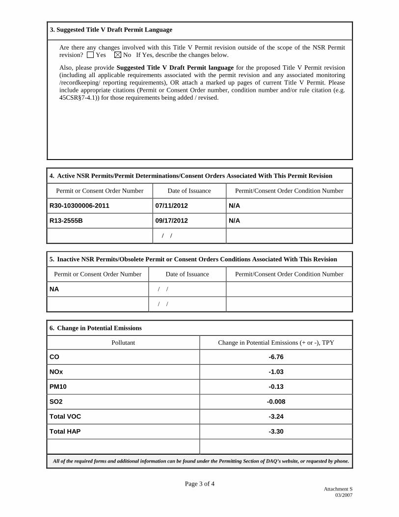
Attachment S
03/2007
Page 3 of 4
3. Suggested Title V Draft Permit Language
Are there any changes involved with this Title V Permit revision outside of the scope of the NSR Permit revision? Yes No If Yes, describe the changes below.
Also, please provide Suggested Title V Draft Permit language for the proposed Title V Permit revision (including all applicable requirements associated with the permit revision and any associated monitoring /recordkeeping/ reporting requirements), OR attach a marked up pages of current Title V Permit. Please include appropriate citations (Permit or Consent Order number, condition number and/or rule citation (e.g. 45CSR§7-4.1)) for those requirements being added / revised.
4. Active NSR Permits/Permit Determinations/Consent Orders Associated With This Permit Revision
Permit or Consent Order Number Date of Issuance Permit/Consent Order Condition Number
R30-10300006-2011 07/11/2012 N/A
R13-2555B 09/17/2012 N/A
/ /
5. Inactive NSR Permits/Obsolete Permit or Consent Orders Conditions Associated With This Revision
Permit or Consent Order Number Date of Issuance Permit/Consent Order Condition Number
NA / /
/ /
6. Change in Potential Emissions
Pollutant Change in Potential Emissions (+ or -), TPY
CO -6.76
NOx -1.03
PM10 -0.13
SO2 -0.008
Total VOC -3.24
Total HAP -3.30
All of the required forms and additional information can be found under the Permitting Section of DAQ’s website, or requested by phone.