domino 48 xt domino 96 xt - adbstagelight.com · 3.6.3 wheel for editor ... 11.6 chaser intensity...
TRANSCRIPT
User ManualIssue 1.1
DOMINO 48 XT DOMINO 96 XT
ME 1183 1106.01.183
Lighting Technologies

DOMINO 48 XT & 96 XT USER MANUAL
www.adblighting.com User Manual - page 1
Issue 1.1
CONTENT
CONTENT ............................................................................................................................................... 1
FOREWORD ........................................................................................................................................... 9
1. Introduction ................................................................................................................................. 10
1.1 Delivery and Unpacking ....................................................................................................... 10 1.2 Preparing the Desk Location ................................................................................................ 10 1.3 DOMINO 48 XT & 96 XT ...................................................................................................... 10 1.4 Power Supply ....................................................................................................................... 11 1.5 Electrical Connection ........................................................................................................... 11 1.6 DESK RANGE ...................................................................................................................... 11
1.6.1 MAIN FEATURES ............................................................................................................ 12 1.6.2 OPTIONS and ACCESSORIES ....................................................................................... 13 1.6.3 CHARACTERISTICS ....................................................................................................... 13
1.7 CARING FOR YOUR DOMINO ........................................................................................... 13 1.8 TERMINOLOGY ................................................................................................................... 14
1.8.1 SECONDARY FUNCTIONS ............................................................................................ 14 1.9 SOFTWARE ......................................................................................................................... 14
2. GETTING CONNECTED .............................................................................................................. 15
2.1 POWER INPUT .................................................................................................................... 15 2.2 DMX DIGITAL OUTPUT (DMX 512) .................................................................................... 15 2.3 VIDEO MONITOR ................................................................................................................ 15 2.4 SWITCHING ON .................................................................................................................. 15 2.5 SWITCHING OFF ................................................................................................................ 15 2.6 POWER SUPPLY RESET ................................................................................................... 16 2.7 FUSE .................................................................................................................................... 16 2.8 AUDIO INPUT ...................................................................................................................... 16 2.9 DESK LAMP ......................................................................................................................... 16 2.10 USB ...................................................................................................................................... 16
3. FRONT PANEL LAYOUT ............................................................................................................ 17
3.1 BANKS ................................................................................................................................. 17 3.2 MODE ................................................................................................................................... 17
3.2.1 MODE SELECTION ......................................................................................................... 18 3.3 CROSS FADE (PLAYBACK) ............................................................................................... 18 3.4 CUE LIST ............................................................................................................................. 18 3.5 MASTERS ............................................................................................................................ 18 3.6 RECORD and EDITOR ........................................................................................................ 18
3.6.1 RECORD BUTTONS ....................................................................................................... 18 3.6.2 EDITOR BUTTONS ......................................................................................................... 18 3.6.3 WHEEL FOR EDITOR ..................................................................................................... 19
3.7 LED display .......................................................................................................................... 19 3.8 Moving light control module ................................................................................................. 19
4. CONCEPT OF THE DOMINO ...................................................................................................... 20
4.1 Overview .............................................................................................................................. 20 4.2 Manual Domino .................................................................................................................... 20 4.3 Theatrical Domino ................................................................................................................ 20 4.4 Live Domino ......................................................................................................................... 20 4.5 Moving light control module ................................................................................................. 21
5. MANUAL MODE ........................................................................................................................... 22
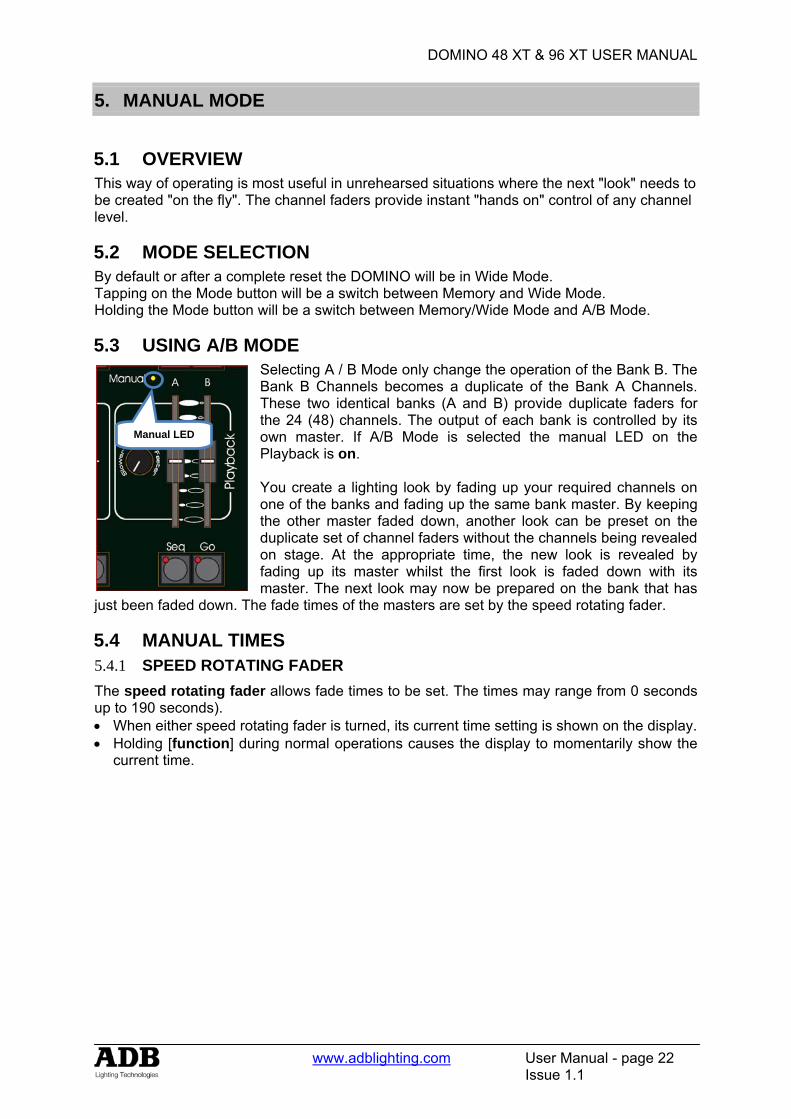
5.1 Overview .............................................................................................................................. 22 5.2 MODE SELECTION ............................................................................................................. 22 5.3 Using A/B Mode ................................................................................................................... 22 5.4 Manual Times ....................................................................................................................... 22
DOMINO 48 XT & 96 XT USER MANUAL
www.adblighting.com User Manual - page 2
Issue 1.1
5.4.1 SPEED ROTATING FADER ............................................................................................ 22 5.4.2 A PRESET AND B PRESET ............................................................................................ 23 5.4.3 Accelerate and slow down ............................................................................................... 23
5.5 Submasters in A/B Mode ..................................................................................................... 23
6. THEATRICAL MEMORIES .......................................................................................................... 24
6.1 OVERVIEW .......................................................................................................................... 24 6.2 RECORDING THEATRICAL MEMORY .............................................................................. 24
6.2.1 THEATRICAL MEMORIES NUMBERS (AND POINT THEATRICAL MEMORIES) ....... 24 6.3 FADE AND LINK TIMES ...................................................................................................... 24
6.3.1 LINK TIMES ..................................................................................................................... 24 6.4 NAMING Theatrical memories ............................................................................................. 25 6.5 EDITING A Theatrical Memory ............................................................................................ 25
6.5.1 CHANNEL LEVELS ......................................................................................................... 25 6.5.2 FADE TIMES ................................................................................................................... 25
6.6 Removing a Theatrical Memory ........................................................................................... 26 6.7 REMOVING (DELETING) the Theatrical Memory List ........................................................ 26 6.8 COPYING ............................................................................................................................. 26
6.8.1 THEATRICAL MEMORY TO SUBMASTER MEMORY .................................................. 26 Not implemented at writing of manual .......................................................................................... 26 6.8.2 SUBMASTER MEMORY TO THEATRICAL MEMORY ................................................. 26
7. THEATRICAL CROSS FADE ...................................................................................................... 27
7.1 Overview .............................................................................................................................. 27 7.1.1 MODE SELECTION ......................................................................................................... 27
7.2 Assigning the x-fade ............................................................................................................. 27 7.2.1 CHANGING THE ASSIGNED MEMORY IN THE PRESET ............................................ 27
7.3 X-Fade VIDEO ..................................................................................................................... 27 7.4 X-fade Modes ....................................................................................................................... 27
7.4.1 NON-SEQUENTIAL ......................................................................................................... 27 7.4.2 SEQUENTIAL .................................................................................................................. 27
7.5 Using the playback with manual fades ................................................................................. 28 7.5.1 CONTINUING A MANUAL FADE AUTOMATICALLY ..................................................... 28
7.6 Using the playback with timed fades .................................................................................... 28 7.6.1 CONTINUING AN AUTOMATIC FADE MANUALLY ....................................................... 29 7.6.2 MODIFYING THE SPEED OF AN AUTOMATIC FADE .................................................. 29
7.7 Stage or Preset .................................................................................................................... 29 7.7.1 CHANNEL LEVELS ......................................................................................................... 29 7.7.2 FADE TIMES ................................................................................................................... 29
7.8 Copying from/to stage or preset ........................................................................................... 30 Not implemented at writing of manual .......................................................................................... 30
7.9 CLEARING stage or preset .................................................................................................. 30
8. SUBMASTERS ............................................................................................................................. 31
8.1 OVERVIEW .......................................................................................................................... 31 8.2 Submasters .......................................................................................................................... 31
8.2.1 BANK B AND BANK C ..................................................................................................... 31 8.2.2 SUBMASTER CONTENTS ............................................................................................. 31 8.2.3 PLAYBACK BANK SUBMASTERS ................................................................................. 31 8.2.4 MODE/BANK FREEZE .................................................................................................... 31 8.2.5 RECORD BANK SUBMASTERS ..................................................................................... 32 8.2.6 SELECT BANK SUBMASTERS ...................................................................................... 32 8.2.7 EDIT BANK SUBMASTERS ............................................................................................ 32
9. SUBMASTER MEMORY .............................................................................................................. 33
9.1 OVERVIEW .......................................................................................................................... 33 9.2 RECORDING Submaster MEMORIES ................................................................................ 33
9.2.1 BANK SELECTION .......................................................................................................... 33 9.2.2 NAMING A SUBMASTER MEMORY .............................................................................. 33 9.2.3 SUBMASTER MEMORY PLAYBACK IN SUBMASTERS .............................................. 34 9.2.4 CONTROLLING A SUBMASTER MEMORY IN A SUBMASTER ................................... 34
DOMINO 48 XT & 96 XT USER MANUAL
www.adblighting.com User Manual - page 3
Issue 1.1
9.2.5 FADE TIMES ................................................................................................................... 34 9.2.6 EDITING IN A SUBMASTER ........................................................................................... 34 9.2.7 CHANNEL LEVELS ......................................................................................................... 35 9.2.8 FADE TIMES ................................................................................................................... 35 9.2.9 EDITING A SUBMASTER MEMORY NAME ................................................................... 35 9.2.10 COPYING A SUBMASTER MEMORY ........................................................................ 35 9.2.11 REMOVING (DELETING) A S SUBMASTER MEMORY ............................................ 36
10. TIMES ........................................................................................................................................... 37
10.1 Overview .............................................................................................................................. 37 10.1.1 UP TIME (IN) ............................................................................................................... 37 10.1.2 DOWN TIME (OUT) ..................................................................................................... 37
10.2 Submaster Times ................................................................................................................. 37 10.2.1 SPEED ROTATING FADER ....................................................................................... 37 10.2.2 SUBMASTER TIME DIFFERENT THAN SUBMASTER MEMORY TIME – SELECT FUNCTION ................................................................................................................................... 37
10.3 THEATRICAL MEMORY TIMES.......................................................................................... 38 10.4 CHASERS TIMES ................................................................................................................ 38 10.5 CUE LISTS TIMES ............................................................................................................... 38
11. CHASERS .................................................................................................................................... 39
11.1 OVERVIEW .......................................................................................................................... 39 11.2 CHASER TERMINOLOGY ................................................................................................... 39
11.2.1 BOUNCE ..................................................................................................................... 39 11.2.2 SINGLE SHOT ............................................................................................................ 39 11.2.3 CHASER CROSSFADE .............................................................................................. 39
11.3 CHASER RECORDING ....................................................................................................... 39 11.3.1 REMOVING STEPS .................................................................................................... 40 11.3.2 CHASER SPEED ........................................................................................................ 40 11.3.3 CHASER CROSSFADE .............................................................................................. 40 11.3.4 COMPLETING THE CHASER .................................................................................... 40
11.4 NAMING A CHASER ........................................................................................................... 40 11.5 CHASER PLAYBACK .......................................................................................................... 40
11.5.1 SUBMASTERS ............................................................................................................ 40 11.6 CHASER INTENSITY .......................................................................................................... 41 11.7 CONTROLLING A CHASER ................................................................................................ 41
11.7.1 STEPPING A CHASER ............................................................................................... 41 11.7.2 RUNNING A SINGLE SHOT ....................................................................................... 41 11.7.3 GLOBAL SPEED CONTROL ...................................................................................... 41
11.8 EDITING A CHASER ........................................................................................................... 42 11.8.1 ADD A STEP ............................................................................................................... 43 11.8.2 REMOVE A STEP ...................................................................................................... 43 11.8.3 MODIFY A STEP ......................................................................................................... 43 11.8.4 EDITING A CHASER NAME ....................................................................................... 44
11.9 COPYING A CHASER ......................................................................................................... 44 11.10 REMOVING A CHASER .................................................................................................. 44
12. CUE LIST ...................................................................................................................................... 45
12.1 OVERVIEW .......................................................................................................................... 45 12.2 RECORDING A CUE LIST ................................................................................................... 45
12.2.1 REMOVING STEPS .................................................................................................... 45 12.2.2 FADE AND LINK TIMES ............................................................................................. 45
12.3 NAMING A CUE LIST .......................................................................................................... 46 12.3.1 NAMING EACH STEP IN A CUE LIST ....................................................................... 46
12.4 CUE LIST PLAYBACK ......................................................................................................... 46 12.4.1 PLAYBACK OF THE THEATRICAL MEMORY LIST .................................................. 46 12.4.2 CUE LIST INTENSITY LEVEL .................................................................................... 46 12.4.3 CUE LIST VIDEO ........................................................................................................ 46 12.4.4 STARTING A CROSSFADE ....................................................................................... 46 12.4.5 CROSSFADING TO THE PREVIOUS STEP .............................................................. 47 12.4.6 STOPPING A CROSSFADE ....................................................................................... 47

DOMINO 48 XT & 96 XT USER MANUAL
www.adblighting.com User Manual - page 4
Issue 1.1
12.4.7 STARTING A STOPPED CROSSFADE ..................................................................... 47 12.4.8 REVERSING A CROSSFADE .................................................................................... 47 12.4.9 STEPPING A CUE LIST .............................................................................................. 47 12.4.10 RANDOM STEP SELECTION ..................................................................................... 47
12.5 CUE LIST TIMES ................................................................................................................. 48 12.5.1 FADE TIMES ............................................................................................................... 48 12.5.2 LINK TIMES ................................................................................................................. 48
12.6 EDITING A CUE LIST .......................................................................................................... 48 12.6.1 ADD A STEP ............................................................................................................... 48 12.6.2 REMOVE A STEP ....................................................................................................... 49 12.6.3 EDIT THE TIMES OF A STEP .................................................................................... 49 12.6.4 EDIT THE CHANNELS LEVELS OF A STEP ............................................................. 49 12.6.5 NAMING EACH STEP IN A CUE LIST ....................................................................... 49 12.6.6 ENDING EDIT ............................................................................................................. 50 12.6.7 EDITING A CUE LIST NAME ...................................................................................... 50
12.7 COPYING A CUE LIST ........................................................................................................ 50 12.8 REMOVING (DELETING) A CUE LIST ............................................................................... 50 12.9 CLEARING THE CUE LIST MASTER ................................................................................. 50
13. FLASH .......................................................................................................................................... 51
13.1 OVERVIEW .......................................................................................................................... 51 13.2 ADD/SOLO MODE ............................................................................................................... 51 13.3 FLASH LEVEL ..................................................................................................................... 51
14. PATCH .......................................................................................................................................... 52
14.1 OVERVIEW .......................................................................................................................... 52 14.2 PATCHING DIMMERS ......................................................................................................... 52
14.2.1 REMOVE All PATCHES .............................................................................................. 52 14.2.2 PATCHING .................................................................................................................. 52 14.2.3 PATCHING MULTIPLE SLOTS .................................................................................. 52 14.2.4 SET A PATCH LEVEL ................................................................................................. 53 14.2.5 UNPATCH A DMX SLOT FROM A CHANNEL ........................................................... 53 14.2.6 1 TO 1 PATCH ............................................................................................................ 53
14.3 PATCHING FIXTURES ........................................................................................................ 53 14.3.1 TEMPLATE LIBRARY ................................................................................................. 53 14.3.2 VIEW LIBRARY CONTENTS ...................................................................................... 53 14.3.3 ADDING TEMPLATES ................................................................................................ 54 14.3.4 ADDING ALL TEMPLATES ......................................................................................... 54 14.3.5 COPY A TEMPLATE TO A USB DEVICE .................................................................. 54 14.3.6 REMOVE A TEMPLATE ............................................................................................. 54 14.3.7 REMOVE ALL TEMPLATES ....................................................................................... 54 14.3.8 CLEARING THE PATCH ............................................................................................. 54 14.3.9 PATCHING FIXTURES ............................................................................................... 54 14.3.10 LOADING TEMPLATES INTO THE PATCH ............................................................... 55 14.3.11 DMX SLOT AND FIXTURE NUMBER ........................................................................ 55 14.3.12 PATCHING MULTIPLE FIXTURES ............................................................................ 56 14.3.13 PATCHING SCROLLERS OR FIXTURES WITH EXTERNAL DIMMERS ................. 56 14.3.14 INTENSITY PATCH LEVEL ........................................................................................ 56 14.3.15 PATCH INDICATORS ................................................................................................. 56 14.3.16 REMOVING A FIXTURE FROM THE PATCH ............................................................ 57 14.3.17 REMOVING A TEMPLATE FROM THE PATCH ........................................................ 57 14.3.18 LOADING SHOWS CONTAINING TEMPLATES ....................................................... 57 14.3.19 EDITING FIXTURE NAMES ........................................................................................ 57 14.3.20 SAVING A PATCH ...................................................................................................... 57 14.3.21 INVERT PAN OR TILT ................................................................................................ 58
15. CONCEPTS FIXTURE PROGRAMMING .................................................................................... 59
15.1 OVERVIEW .......................................................................................................................... 59 15.2 THEATRICAL REHEARSED. .............................................................................................. 59 15.3 ON THE FLY ........................................................................................................................ 59 15.4 OUTPUT PHILOSOPHY ...................................................................................................... 60
DOMINO 48 XT & 96 XT USER MANUAL
www.adblighting.com User Manual - page 5
Issue 1.1
15.4.1 LTP and Theatrical memories / Submaster memories ................................................ 60 15.5 COMBINING THEATRICAL AND ON THE FLY .................................................................. 60 15.6 FIXTURE INTENSITY CONTROL ....................................................................................... 61
15.6.1 INDIVIDIDUAL FIXTURES .......................................................................................... 61 15.6.2 MEMORY PLAYBACK ................................................................................................ 61 15.6.3 FIXTURE INTENSITY MEMORIES ............................................................................. 61
16. BASIC PROGRAMMING MOVING LIGHT CONTROL MODULE .............................................. 62
16.1 OVERVIEW .......................................................................................................................... 62 16.2 FADING UP FIXTURES ....................................................................................................... 62 16.3 GETTING FIXTURES ONTO THE moving light control module ........................................ 62 16.4 ALL MODE ........................................................................................................................... 63 16.5 SELECTING A FIXTURE ..................................................................................................... 63 16.6 CONTROLLING THE SELECTED FIXTURE ...................................................................... 63 16.7 ADJUSTING PARAMETER VALUES .................................................................................. 64
16.7.1 VARIABLE PARAMETERS ......................................................................................... 64 16.7.2 TRACKBALL (MOUSE) FOR PAN AND TILT ............................................................. 65 16.7.3 WHEEL STOPS ........................................................................................................... 65 16.7.4 VARIABLES WITHIN WHEEL STOPS ........................................................................ 65 16.7.5 PARAMETER TIMES .................................................................................................. 65 16.7.6 HOME .......................................................................................................................... 65 16.7.7 FILTERS ...................................................................................................................... 65 16.7.8 HI-LIGHTS ................................................................................................................... 66
16.8 VIEW .................................................................................................................................... 66 16.9 SAVING THEATRICAL MEMORIES ................................................................................... 67 16.10 SAVING SUBMASTER MEMORIES ............................................................................... 67 16.11 BUILDING BLOCK MEMORIES ...................................................................................... 67 16.12 SAVING CHASERS ......................................................................................................... 67
17. FIXTURE PLAYBACK ................................................................................................................. 68
17.1 OVERVIEW .......................................................................................................................... 68 17.2 THEATRICAL AND SUBMASTER MEMORIES PLAYBACK .............................................. 68 17.3 MOVING LIGHT CONTROL MODULE TRIGGER .............................................................. 68 17.4 MEMORIES FLASH ............................................................................................................. 69 17.5 MOVING LIGHT CONTROL MODULE LOCK ..................................................................... 69 17.6 PALETTE PLAYBACK (E-MOD) .......................................................................................... 69 17.7 PRESET PLAYBACK (P-MOD) ........................................................................................... 69 17.8 CHASER PLAYBACK .......................................................................................................... 69 17.9 COMBINING AND VARYING CHASERS ............................................................................ 69
17.9.1 CHASER TIMES .......................................................................................................... 70
18. ADVANCED FIXTURE PROGRAMMING .................................................................................... 71
18.1 LOADING FIXTURES .......................................................................................................... 71 18.2 ALL MODE ........................................................................................................................... 71 18.3 CLEARING FIXTURES ........................................................................................................ 71 18.4 HOME ................................................................................................................................... 71 18.5 P-TRIG ................................................................................................................................. 72 18.6 PARAMETER TIMES ........................................................................................................... 72
18.6.1 DEFAULT PARAMETER TIMES ................................................................................. 74 18.6.2 SAVING TIMES ........................................................................................................... 74
18.7 GROUPS .............................................................................................................................. 75 18.7.1 GROUP NUMBERING ................................................................................................ 75 18.7.2 STORING GROUPS.................................................................................................... 75 18.7.3 LOADING GROUPS .................................................................................................... 76 18.7.4 Changing Hi-Lights Using Groups ............................................................................... 76 18.7.5 Naming Groups ........................................................................................................... 76 18.7.6 Copy Group ................................................................................................................. 76
18.8 FILTERS ............................................................................................................................... 77 18.8.1 APPLY FILTERS ......................................................................................................... 77 18.8.2 FILTER INDICATORS ................................................................................................. 77 18.8.3 AUTOMATIC FILTERS ............................................................................................... 77
DOMINO 48 XT & 96 XT USER MANUAL
www.adblighting.com User Manual - page 6
Issue 1.1
18.8.4 STORING ALTERED PARAMETERS ......................................................................... 78 18.8.5 CLEARING FILTERS .................................................................................................. 78 18.8.6 CLEARING ALL FILTERS ........................................................................................... 78 18.8.7 FILTER MEMORY ....................................................................................................... 78 18.8.8 NAMING FILTER MEMORIES .................................................................................... 78 18.8.9 COPY FILTER ............................................................................................................. 78
18.9 HI-LIGHTS............................................................................................................................ 79 18.9.1 CONTROLLING HI-LIGHTS USING GROUPS .......................................................... 79
18.10 PRESETS ........................................................................................................................ 79 18.10.1 PRESET NUMBERING ............................................................................................... 80 18.10.2 STORING A PRESET ................................................................................................. 80 18.10.3 APPLYING A PRESET ................................................................................................ 80 18.10.4 LINKING A PRESET TO A MEMORY ......................................................................... 80 18.10.5 CLEARING PARAMETER LINKS TO A PRESET ...................................................... 81 18.10.6 REMOVING A LINK TO A PRESET FROM A MEMORY ........................................... 81 18.10.7 NAMING PRESETS .................................................................................................... 81 18.10.8 COPY PRESET ........................................................................................................... 81 18.10.9 LOADING THE Moving light control module WITH THE FIXTURES IN A PRESET . 81 18.10.10 EDIT A PRESET .......................................................................................................... 81 18.10.11 PRESET PLAYBACK (P-Mod) .................................................................................... 81
18.11 PALETTES ....................................................................................................................... 82 18.11.1 PALETTE NUMBERING ............................................................................................. 82 18.11.2 STORING A PALETTE ................................................................................................ 82 18.11.3 APPLYING A PALETTE .............................................................................................. 83 18.11.4 LINKING A PALETTE TO A MEMORY ....................................................................... 83 18.11.5 CLEARING PARAMETER LINKS TO PALETTES ...................................................... 83 18.11.6 REMOVING A LINK TO A PALETTE FROM A MEMORY .......................................... 83 18.11.7 NAMING PALETTES ................................................................................................... 83 18.11.8 COPY PALETTE ......................................................................................................... 84 18.11.9 LOADING THE Moving light control module WITH THE FIXTURES IN A PALETTE 84 18.11.10 EDITING PALETTES .................................................................................................. 84 18.11.11 PALETTE PLAYBACK (E-Mod) .................................................................................. 84 18.11.12 SAVING / LOADING PALETTES ................................................................................ 84
18.12 COMBINING Moving light control module FUNCTIONS ................................................. 84 18.13 CLONE ............................................................................................................................. 85 18.14 SAVING MEMORIES ....................................................................................................... 86
18.14.1 NO STORE PARAMETERS ........................................................................................ 86 18.14.2 CLEARING PARAMETERS ........................................................................................ 87 18.14.3 STORING INTENSITY ONLY MEMORIES ................................................................. 87 18.14.4 STORING ONLY ALTERED PARAMETERS .............................................................. 87
18.15 DIRECT ATTRIBUTE CONTROL .................................................................................... 87
19. EFFECTS ...................................................................................................................................... 88
19.1 OVERVIEW .......................................................................................................................... 88 19.2 BASIC EFFECT OPERATIONS ........................................................................................... 88 19.3 STOPPING EFFECTS ......................................................................................................... 89 19.4 EFFECT MENUS ................................................................................................................. 89 19.5 SUB MENUS ........................................................................................................................ 90 19.6 DETAILED MENU DESCRIPTIONS .................................................................................... 90
19.6.1 SHAPE ........................................................................................................................ 90 19.6.2 SIZE ............................................................................................................................. 91 19.6.3 PHASE ........................................................................................................................ 91 19.6.4 SPREAD ...................................................................................................................... 92 19.6.5 RATE ........................................................................................................................... 92 19.6.6 CYCLES ...................................................................................................................... 93 19.6.7 CONTRL ...................................................................................................................... 93 19.6.8 CUSTOM SHAPES ..................................................................................................... 93
19.7 COPYING EFFECTS ........................................................................................................... 94
20. FANS ............................................................................................................................................ 95
20.1 OVERVIEW .......................................................................................................................... 95
DOMINO 48 XT & 96 XT USER MANUAL
www.adblighting.com User Manual - page 7
Issue 1.1
20.2 FAN FUNCTIONS ................................................................................................................ 95 20.3 FANNING ORDER ............................................................................................................... 96 20.4 STORING FAN ORDERS .................................................................................................... 97 20.5 FANNING TIMES ................................................................................................................. 97 20.6 SAVING FANS ..................................................................................................................... 97
21. VIDEO ........................................................................................................................................... 99
21.1 VIDEO OVERVIEW .............................................................................................................. 99 21.2 MAIN DISPLAY .................................................................................................................... 99
21.2.1 Intensity levels ........................................................................................................... 100 21.2.2 Submasters ............................................................................................................... 100 21.2.3 Theatrical Crossfade ................................................................................................. 101
21.3 SELECTABLE AREAS ....................................................................................................... 101 21.3.1 PINNED VIDEO ......................................................................................................... 101
21.4 VIDEO 1 TO 4 .................................................................................................................... 101 21.4.1 VIDEO PAGE 1 – CHANNEL VIEW .......................................................................... 102 21.4.2 VIDEO 2 – OUTPUT & PATCH ................................................................................. 102 21.4.3 VIDEO 3 – Theatrical Crossfade and Cue list ........................................................... 103 21.4.4 VIDEO 4 – Moving light control module VIEW .......................................................... 103 21.4.5 PAD View .................................................................................................................. 103 21.4.6 Moving light control module Mimic Window .............................................................. 104
21.5 FIXTURE POP-UP WINDOW ............................................................................................ 104 21.6 GROUP POP-UP WINDOW .............................................................................................. 104 21.7 PALETTE POP-UP WINDOW ............................................................................................ 105 21.8 PRESET POP-UP WINDOW ............................................................................................. 105 21.9 FILTER POP-UP WINDOW ............................................................................................... 105 21.10 PLAYBACK BANK MEMORIES .................................................................................... 105
22. STL (SOUND TO LIGHT) and SyncoBEAT .............................................................................. 106
22.1 OVERVIEW ........................................................................................................................ 106 22.2 CONNECT STL TO CHASER ............................................................................................ 106
22.2.1 CONNECT TO SUBMASTER ................................................................................... 106 22.2.2 CONNECT TO CHASER. .......................................................................................... 106
22.3 CONNECTED STL INDICATORS ..................................................................................... 107 22.4 STL (SOUND TO LIGHT) MODE ....................................................................................... 107 22.5 SYNCOBEAT MODE ......................................................................................................... 108
23. Midi ............................................................................................................................................. 109
23.1 OVERVIEW ........................................................................................................................ 109 23.2 MIDI NOTES ...................................................................................................................... 109 23.3 Control Button mapping ..................................................................................................... 110
24. UTILITIES ................................................................................................................................... 111
24.1 STORAGE OPERATIONS ................................................................................................. 111 24.1.1 SAVE SHOW ............................................................................................................. 111 24.1.2 LOAD SHOW ............................................................................................................. 111
24.2 RESET ............................................................................................................................... 111 24.2.1 SYSTEM RESET ....................................................................................................... 111 24.2.2 TOTAL RESET .......................................................................................................... 111 24.2.3 POWER ON RESETS ............................................................................................... 111
24.3 Memory Protect .................................................................................................................. 112 24.3.1 UNLOCK .................................................................................................................... 112 24.3.2 LOST LOCK CODE ................................................................................................... 112
24.4 MIDI .................................................................................................................................... 112 24.5 SETUP PREFERENCES ................................................................................................... 113
24.5.1 DEFAULT FADE AND SPEED TIMES ...................................................................... 113 24.6 LANGUAGE ....................................................................................................................... 113 24.7 DEFAULT FILE NAME ....................................................................................................... 113 24.8 B MASTER INVERTED ...................................................................................................... 113 24.9 SOFTWARE UPGRADE .................................................................................................... 113
24.9.1 OVERVIEW ............................................................................................................... 113
DOMINO 48 XT & 96 XT USER MANUAL
www.adblighting.com User Manual - page 8
Issue 1.1
24.9.2 USB DEVICE UPLOAD ............................................................................................. 114 24.9.3 CODELINK ................................................................................................................ 114
24.10 DIAGNOSTICS .............................................................................................................. 114 24.10.1 DIAGNOSTICS MODE .............................................................................................. 114 24.10.2 LED AND BUTTON TEST ......................................................................................... 114 24.10.3 FADER TEST ............................................................................................................ 114 24.10.4 EDIT WHEEL TEST .................................................................................................. 114 24.10.5 BATTERY TEST ........................................................................................................ 115 24.10.6 SYSTEM ERROR INFORMATION ........................................................................... 115 24.10.7 MEMORY TEST ........................................................................................................ 115
DOMINO 48 XT & 96 XT USER MANUAL
www.adblighting.com User Manual - page 9
Issue 1.1
FOREWORD
This issue 1.1 of the User Manual for DOMINO 48 XT and DOMINO 96 XT. The latest version of ADB User Manuals is available from the ADB website. www.adblighting.com > ADB Products > Product family > Product For DOMINO 48 XT and DOMINO 96 XT www.adblighting.com > ADB Products > Control Desks > Memory Control Desks The functions described in this User Manual require the latest software version. The latest software version is available on the http://www.adblighting.com web site. For DOMINO 48 XT and DOMINO 96 XT www.adblighting.com > Downloads > MIKADO and DOMINO Updates to this version of the user manual will follow. Have fun with the DOMINO Zaventem, October 2010.
DOMINO 48 XT & 96 XT USER MANUAL
www.adblighting.com User Manual - page 10
Issue 1.1
1. Introduction
1.1 DELIVERY AND UNPACKING As soon as you receive your equipment, open the boxes and inspect the items received. If you discover any damage, contact the carrier immediately and make any necessary claim for the problems discovered. The equipment was checked before being packed and left our factory in perfect condition. Check that the equipment supplied to you corresponds to the consignment note and that this corresponds to your order. You will find the references of your desk on an identification label affixed to the rear panel. If there is any discrepancy in the order and delivery, contact your supplier immediately who will clarify the situation to your full satisfaction. Permissible storage conditions: Temperature: -10 to +50° C: variation rate: 20°/hour Relative humidity: 20 to 80 % without condensation.
1.2 PREPARING THE DESK LOCATION The surface of your work area should be smooth, level and sturdy. Make sure that there is enough clearance around the desk to:
• open the desk • access the rear connections • allow air circulation around vents to prevent the desk from over-heating.
1.3 DOMINO 48 XT & 96 XT The DOMINO desk is a professional lighting console, it is Class I equipment designed and manufactured to the EN60950 standard. THIS EQUIPMENT MUST BE EARTHED. No special undertaking need to be made for the installation of the equipment. The room in which the equipment is to be installed must be clean, dust-free and have a temperature between 5 and 35° C and a relative humidity from 20 to 80 % without condensation. Consumption of food and drink over the desk is inadvisable to avoid it being accidentally dropped into the equipment and impairing certain functions. The desk and the monitor should be installed on a table or a console. Like all equipment that includes microprocessors and uses similar technology, the desk is sensitive to the influences of static electricity and it is possible that these influences will affect functioning in certain circumstances. If this is the case, it will be necessary to place anti-static carpets on the floor and perhaps to make the atmosphere more humid. Whenever a carpet is to be used, it must be an antistatic carpet. In order to avoid wasting time and possibly damaging the equipment, the installer is invited to scrupulously follow the instructions in the diagrams shown, and on the rear panel of the desk. Before powering up the desk or any of its peripherals, check that the existing voltages are within the limits defined in the GETTING CONNECTED SECTION paragraph. Note: all connections should be made with the power turned off, otherwise functioning may
be affected and can even damage the equipment under certain conditions.
DOMINO 48 XT & 96 XT USER MANUAL
www.adblighting.com User Manual - page 11
Issue 1.1
1.4 POWER SUPPLY As all equipment used in computer systems, your system is sensitive to the characteristics of the network and in particular to variations and voltage peaks. Consequently, we advise you to use an appropriate line conditioner on this equipment. Please consult us if you are in any doubt about this. The line is to be protected by fuse or by circuit breakers and is to be provided with an earth connection for personal safety. Important Notice for Power Cables Power cables and connectors are an important part of your equipment and contribute to its safety. Always use the connector to make or interrupt the link; never pull on the cable. Do not damage the cable or the connectors in any way; do not pinch or tie together power supply and signal cables, check them at each installation and at regular intervals on a permanent installation.
1.5 ELECTRICAL CONNECTION TO PREVENT THE RISK OF ELECTRIC SHOCK, DO NOT OPEN THE DESK. THERE ARE NO USER SERVICEABLE PARTS WITHIN. REFER SERVICING TO QUALIFIED ENGINEERS ONLY. LETHAL VOLTAGES ARE PRESENT INSIDE! ALWAYS DISCONNECT FROM THE POWER SUPPLY BEFORE OPENING FOR INSPECTION. DOMINO is a professional lighting control systems developed with simplicity of use in mind. In order to maintain the proficiency of the built in safety features, this equipment shall be installed and maintained by qualified service personnel only.
1.6 DESK RANGE DOMINO 48 XT: 48 channels, 1024 DMX channel console, 1 SVGA output DOMINO 48 XT M: 48 channels, 1024 DMX channel console, 1 SVGA output + Motion
control module DOMINO 96 XT: 96 channels, 1024 DMX channel console, 1 SVGA output DOMINO 96 XT M: 96 channels, 1024 DMX channel console, 1 SVGA output + Motion
control module Motion control module consists of: Moving light control module, for controlling up to 128 moving lights, on DOMINO 48 XT M & 96 XT M as standard, and on DOMINO 48 XT & 96 XT as retrofit option:
• Powerful effects engine and automatic fanning of fixtures. • Extensive fixture library with Web updates. • Comprehensive controls for filters, pallets, presets, cloning, groups, storing, lock
home, etc. • 6 touch pad displayers (virtual wheels) for parameter control. • DOMINO 48 XT M: 36 groups, 96 presets, 96 pallets and 378 effects. • DOMINO 96 XT M: 36 groups, 192 presets, 192 pallets, and 594 effects.
DOMINO 48 XT & 96 XT USER MANUAL
www.adblighting.com User Manual - page 12
Issue 1.1
1.6.1 MAIN FEATURES • 48 faders in 2-preset mode or 96 faders in extended mode on DOMINO 96 XT - 24/48
faders on DOMINO 48 XT. • 48 faders configurable as channels, submasters or playbacks on DOMINO 96 XT - 24
faders on DOMINO 48 XT. • 18 dedicated faders configurable in 9 pages as submasters or playbacks. • 4 preset masters-A preset, B preset, C preset and grab. • Theatrical dipless crossfade with 2 general masters, stage and preset, and dedicated
buttons. • Up to 594 memories on DOMINO/XT/96 - 378 on DOMINO/XT/48. • Individual In (Up) and Out (Down) fade times. • Up to 66 playbacks/chasers on DOMINO/XT/96 can be played simultaneously - 43 on
DOMINO/XT/48. • Fully proportional softpatch to 1024 dimmers. • 2-preset, extended & memory modes, each fader with flash button. • LED display showing status information via scrolling messages. • Up to 250 steps of a chaser can be recorded as channels, or Memories/Snapshots. • 1 SVGA output for displaying memories, patch, texts and help menus in multiple
languages. • 1 USB connector for show recording. • MIDI IN/OUT connector for Midi functionality (optional for DOMINO/XT/48 & 96). • Moving light control module, for controlling up to 128 moving lights (on
DOMINO 48 XT M & 96 XT M as standard and on DOMINO 48 XT & 96 XT as retrofit option) and featuring:
o Powerful effects engine and automatic fanning of fixtures. o Extensive fixture library with Web updates. o Comprehensive controls for filters, pallets, presets, cloning, groups, storing,
lock home, etc. o 6 touch pad displayers (virtual wheels) for parameter control. o DOMINO/XT/48/M: 36 groups, 96 presets, 96 pallets and 378 effects. o DOMINO/XT/96/M: 36 groups, 192 presets, 192 pallets and 594 effects.
• 2 DMX512/1990 output on XLR-5F connector. • 90-260 V, 47/63Hz power supply with automatic detection. • This equipment complies with all applicable European directives and carries a CE
mark.
DOMINO 48 XT & 96 XT USER MANUAL
www.adblighting.com User Manual - page 13
Issue 1.1
1.6.2 OPTIONS and ACCESSORIES OPTIONS A number of useful options are available from ADB to compliment the DOMINO lighting desk.
• Moving light control module for controlling moving lights (for retrofitting on DOMINO/XT/48 & DOMINO/XT/96), featuring: - Powerful effects engine and automatic fanning of fixtures. - Extensive fixture library with Web updates. - Comprehensive controls for filters, palettes, presets, cloning, groups, storing, lock
home, etc. - 6 touch pad displayers (virtual wheels) for parameter control. - Module added on DOMINO/XT/96: 36 groups, 96 presets, 96 pallets and 378
effects. - Module added on DOMINO/XT/96: 36 groups, 192 presets, 192 pallets and 594
effects.
ACCESSORIES • USB memory Stick (FLASHMEM) • XLR3 "gooseneck" desk lamp (WORKLITE/XL3) • Dust Cover DOMINO 48 XT (DC/DOM/XT/48) • Dust Cover DOMINO 96 XT (DC/DOM/XT/96) • Flight Case DOMINO 48 XT (FLY/DOM/XT/48) • Flight Case DOMINO 96 XT (FLY/DOM/XT/96)
1.6.3 CHARACTERISTICS Power requirements: 90-260 V, 47-63 Hz power supply with automatic detection. Dimensions: DOMINO XT 48 (Width x Depth x Height): 734 x 535 x 144 mm Net weight: 15.5 kg DOMINO XT 96 (Width x Depth x Height): 974 x 535 x 144 mm Net weight: 26.0 kg
1.7 CARING FOR YOUR DOMINO The DOMINO is manufactured from quality components and will give many years of service if you take some basic precautions.
• Do not allow any liquids or foreign objects to enter the DOMINO. • The inside should be cleaned and dried as soon as possible. Only suitably qualified
personnel should remove the covers and perform any such maintenance. • Do not apply excessive force to any of the controls. Spare parts and service are
available from your ADB distributor, but prevention is better than cure. • When connecting any devices to the DOMINO, make sure that all connections are
correct before switching on the power. If any doubt exists, obtain the assistance of qualified personnel.
• If your DOMINO is to be used "on the road", you should use the optional flight case to protect the desk. Transport the DOMINO with all faders in the fully down position.

DOMINO 48 XT & 96 XT USER MANUAL
www.adblighting.com User Manual - page 14
Issue 1.1
This gives the faders minimum protection from probable damage. When your DOMINO is not in use, cover the upper surface with the optional dust cover. If the surface of your DOMINO becomes soiled, clean it with a damp cloth. Do not use any powerful solvents. An alcohol swab may be used to remove any gum from labelling tape.
• Areas are provided below the faders for you to write identifying labels. To prevent permanent marking of your DOMINO, ADB recommends that you place strips of "write on" tape in these areas.
1.8 TERMINOLOGY Certain button stroke terminology is used throughout this manual to describe the particular operations being undertaken. Any text enclosed in these symbols [ ], refers to when that particular button needs to be pressed. For example; Press [record memory], means to press the record memory button. Flash/assign buttons are often abbreviated to [f/a]. If the button to be pressed is a Flash/Assign button (of which there are many) then it will be identified by naming it as follows; [f/a] (Name). Any information that appears on the LED display is printed in “quotes”. 1.8.1 SECONDARY FUNCTIONS Some f/a buttons have secondary functions that are activated by holding down the [function] button and tapping an [f/a] button. These secondary functions are printed on the front panel below their f/a buttons. Some flash buttons have hidden secondary functions that are activated by holding down the [function] button and tapping the [ok] button. These secondary functions are not labelled but are described in the “Diagnostics” section of the “UTILITIES” section. The buttons below the EDIT wheel have secondary functions in that they are used to answer either “Yes”, “No” or “OK” to questions that appear on the display when you are performing certain actions. They are typically used to confirm or abort the action that you have selected.
1.9 SOFTWARE ADB lighting technologies has a policy of continuous improvement of its products. As the DOMINO is a computerized lighting desk, its software is subject to this policy as new features are added and existing features improved. The software version of your DOMINO is momentarily displayed on the LED display when the DOMINO is switched on. The latest version can be downloaded from the ADB website. http://www.adblighting.com Whilst every care is taken in the preparation of this manual, ADB Lighting Technologies takes no responsibility for any errors or omissions.
DOMINO 48 XT & 96 XT USER MANUAL
www.adblighting.com User Manual - page 15
Issue 1.1
2. GETTING CONNECTED
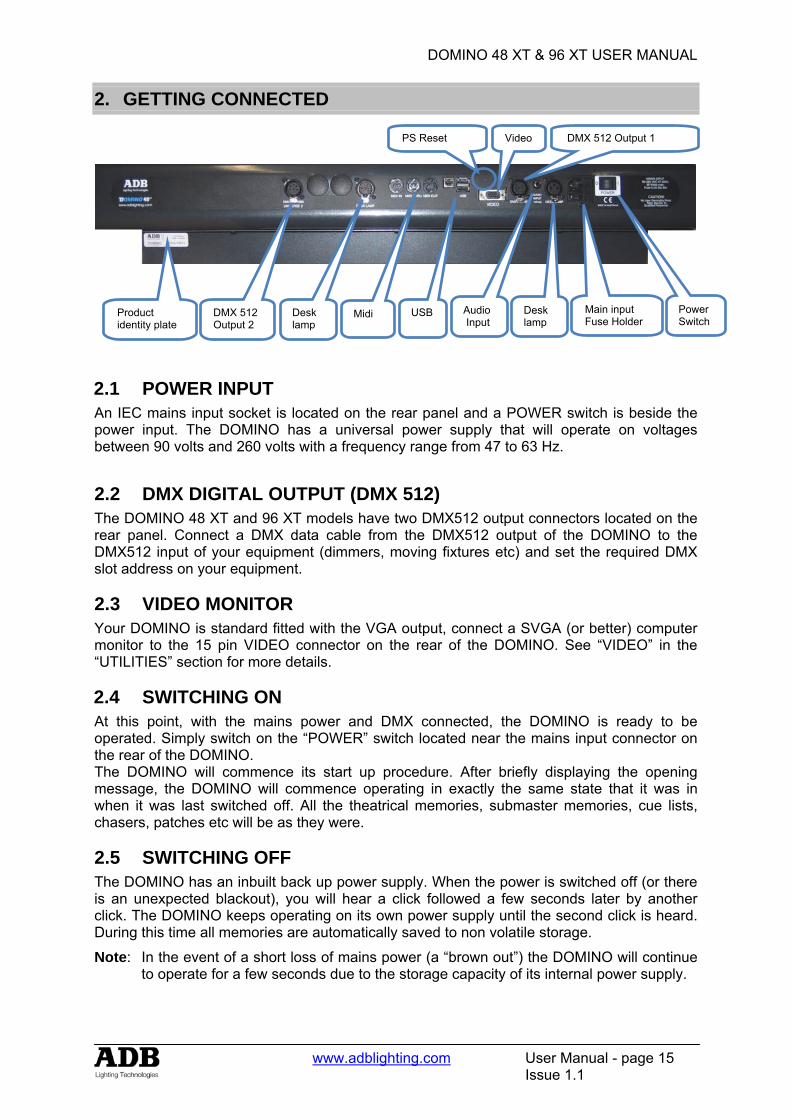
2.1 POWER INPUT An IEC mains input socket is located on the rear panel and a POWER switch is beside the power input. The DOMINO has a universal power supply that will operate on voltages between 90 volts and 260 volts with a frequency range from 47 to 63 Hz.
2.2 DMX DIGITAL OUTPUT (DMX 512) The DOMINO 48 XT and 96 XT models have two DMX512 output connectors located on the rear panel. Connect a DMX data cable from the DMX512 output of the DOMINO to the DMX512 input of your equipment (dimmers, moving fixtures etc) and set the required DMX slot address on your equipment.
2.3 VIDEO MONITOR Your DOMINO is standard fitted with the VGA output, connect a SVGA (or better) computer monitor to the 15 pin VIDEO connector on the rear of the DOMINO. See “VIDEO” in the “UTILITIES” section for more details.
2.4 SWITCHING ON At this point, with the mains power and DMX connected, the DOMINO is ready to be operated. Simply switch on the “POWER” switch located near the mains input connector on the rear of the DOMINO. The DOMINO will commence its start up procedure. After briefly displaying the opening message, the DOMINO will commence operating in exactly the same state that it was in when it was last switched off. All the theatrical memories, submaster memories, cue lists, chasers, patches etc will be as they were.
2.5 SWITCHING OFF The DOMINO has an inbuilt back up power supply. When the power is switched off (or there is an unexpected blackout), you will hear a click followed a few seconds later by another click. The DOMINO keeps operating on its own power supply until the second click is heard. During this time all memories are automatically saved to non volatile storage.
Note: In the event of a short loss of mains power (a “brown out”) the DOMINO will continue to operate for a few seconds due to the storage capacity of its internal power supply.
Product identity plate
Midi USB
Video*
DMX 512 Output 1
Audio Input
Desk lamp
Main input Fuse Holder
Power Switch
PS Reset
DMX 512 Output 2
Desk lamp
DOMINO 48 XT & 96 XT USER MANUAL
www.adblighting.com User Manual - page 16
Issue 1.1
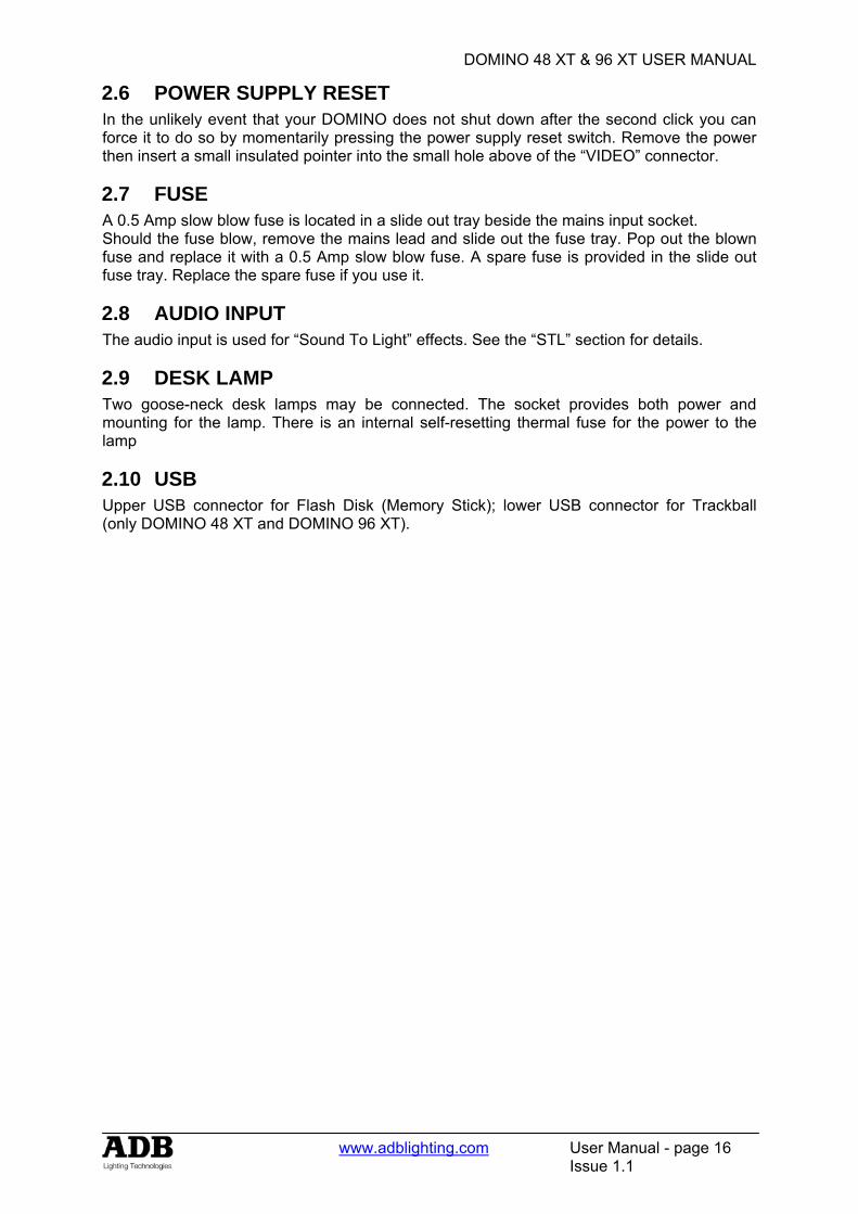
2.6 POWER SUPPLY RESET In the unlikely event that your DOMINO does not shut down after the second click you can force it to do so by momentarily pressing the power supply reset switch. Remove the power then insert a small insulated pointer into the small hole above of the “VIDEO” connector.
2.7 FUSE A 0.5 Amp slow blow fuse is located in a slide out tray beside the mains input socket. Should the fuse blow, remove the mains lead and slide out the fuse tray. Pop out the blown fuse and replace it with a 0.5 Amp slow blow fuse. A spare fuse is provided in the slide out fuse tray. Replace the spare fuse if you use it.
2.8 AUDIO INPUT The audio input is used for “Sound To Light” effects. See the “STL” section for details.
2.9 DESK LAMP Two goose-neck desk lamps may be connected. The socket provides both power and mounting for the lamp. There is an internal self-resetting thermal fuse for the power to the lamp
2.10 USB Upper USB connector for Flash Disk (Memory Stick); lower USB connector for Trackball (only DOMINO 48 XT and DOMINO 96 XT).
DOMINO 48 XT & 96 XT USER MANUAL
www.adblighting.com User Manual - page 17
Issue 1.1
3. FRONT PANEL LAYOUT
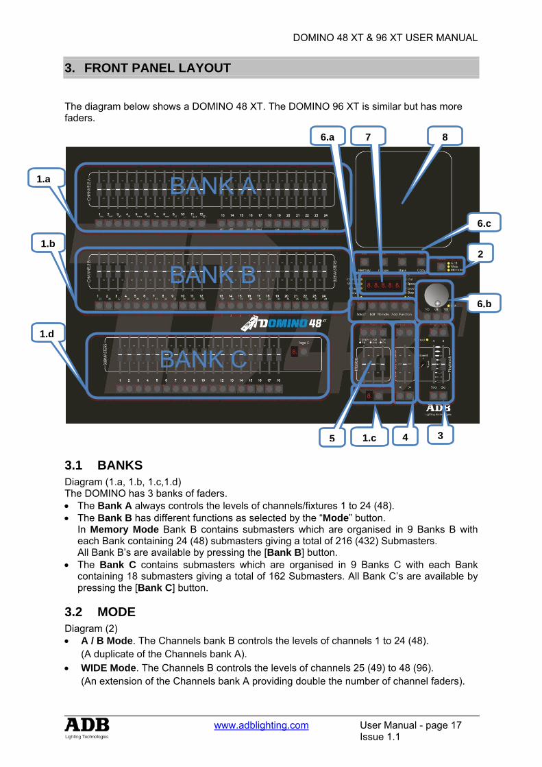
The diagram below shows a DOMINO 48 XT. The DOMINO 96 XT is similar but has more faders.
3.1 BANKS Diagram (1.a, 1.b, 1.c,1.d) The DOMINO has 3 banks of faders. • The Bank A always controls the levels of channels/fixtures 1 to 24 (48). • The Bank B has different functions as selected by the “Mode” button.
In Memory Mode Bank B contains submasters which are organised in 9 Banks B with each Bank containing 24 (48) submasters giving a total of 216 (432) Submasters. All Bank B’s are available by pressing the [Bank B] button.
• The Bank C contains submasters which are organised in 9 Banks C with each Bank containing 18 submasters giving a total of 162 Submasters. All Bank C’s are available by pressing the [Bank C] button.
3.2 MODE Diagram (2) • A / B Mode. The Channels bank B controls the levels of channels 1 to 24 (48).
(A duplicate of the Channels bank A). • WIDE Mode. The Channels B controls the levels of channels 25 (49) to 48 (96).
(An extension of the Channels bank A providing double the number of channel faders).
1.a
1.b
BANK A
5 1.c 4 3
6.b
6.c
2
7
BANK B
6.a
BANK C
8
1.d
DOMINO 48 XT & 96 XT USER MANUAL
www.adblighting.com User Manual - page 18
Issue 1.1
• MEMORY mode. The Channels B faders become SUBMATERS and control the levels of recorded Memories or Chasers.
3.2.1 MODE SELECTION By default or after a complete reset the DOMINO will be in Wide Mode. Tapping on the [Mode] button will be a switch between Memory and Wide Mode. Holding the [Mode] button will be a switch between Memory/Wide Mode and A/B Mode.
3.3 CROSS FADE (PLAYBACK) Diagram (3) The Cross fade (Playback) is an ordered list of actions that will run in succession through the playbacks; usually it is a list of memories. DOMINO has a Dipless Crossfade. A Crossfade is usually executed automatically (GO) but can be manually.
DOMINO’s playback has two faders: • Stage: Effectively live (seen at the desk Output) • Preset: Effectively blind (not seen at the Output).
3.4 CUE LIST Diagram (4) A Cue List is a recorded list of steps that are to be replayed in order. Each step consists of either a Memory, a chaser or a snapshot of the output.
3.5 MASTERS Diagram (5)
• C MASTER : Controls the overall level of the C Submasters. • FLASH MASTER : Controls the overall level of the output of the FLASH. • GRAND MASTER : Controls the overall level of the output of the DOMINO.
3.6 RECORD and EDITOR Diagram (6a, 6b, 6c) 3.6.1 RECORD BUTTONS
• Record Memory to record a theatrical memory, submaster memory, snapshot of the output, a step in a Cue List
• Record Chaser to record a chaser • Record Cue List to record a Cue List • Assign Copy
o Assign a Cue List to the Cross fade and Cue List master. o Copy theatrical memories, submaster memories chasers or Cue Lists from
one submaster to another. o Copy theatrical memories, submaster memories, chasers or Cue Lists to or
from the Grab master. o Copy a Snapshot from the Grab master to a Submaster.
3.6.2 EDITOR BUTTONS • SELECT BUTTON “Select” is most useful for making one off changes during a
performance or for experimenting with changes without affecting the theatrical memories, submaster memories.
DOMINO 48 XT & 96 XT USER MANUAL
www.adblighting.com User Manual - page 19
Issue 1.1
• EDIT BUTTON When pressed, it selects Edit mode. You may then choose to Edit any theatrical memory, submaster memory, Chaser, Cue List, the contents of the Grab master or the Patch (if previously selected via the function button).
• REMOVE BUTTON o Remove the contents of the Cross Fade, Cue List and Grab. o Delete theatrical memories, submaster memories, patches or steps of Cue
List or Chasers. o Remove characters from names.
• ADD BUTTON o Insert steps in a Cue List or chaser when editing. o Add a 1 to 1 patch o Insert spaces in names
• FUNCTION BUTTON
When pressed during normal operations, it causes the display to momentarily show the current times. Subsequent presses will toggle between the two time settings.
3.6.3 WHEEL FOR EDITOR Continuously rotatable in either direction and can be used to:
• Creating Theatrical Memories • Set fade when recording or editing. • Adjust the level of channels when editing.
3.7 LED DISPLAY Diagram (7) The display is used to scroll messages and prompts and to show names and numbers. The small labelled LEDS beside the display are used to define the numbers shown on it.
3.8 MOVING LIGHT CONTROL MODULE The Moving light control module is used to control the parameters of moving fixtures and to “store” their parameter settings into the theatrical memory or into the submaster memories. The Moving light control module is also used to access “groups”, “palettes”, “presets”, “filters”, “effects”, “fans” and fixture patching. The Moving light control module is extensively described in the “BASIC PROGRAMMING MOVING LIGHT CONTROL MODULE” and “ADVANCED PROGRAMMING MOVING LIGHT CONTROL MODULE” sections.
DOMINO 48 XT & 96 XT USER MANUAL
www.adblighting.com User Manual - page 20
Issue 1.1
4. CONCEPT OF THE DOMINO
4.1 OVERVIEW ADB’s DOMINO 48 XT (96 XT) provides the operator with complete command over a lighting control system. DOMINO 48 XT (96 XT) is very easy to use and is highly intuitive. It is not necessary to understand all of the concepts of the system before it can be used: creating lighting looks can be controlled straight away by using only the faders. (Manual DOMINO) However, DOMINO 48 XT (96 XT can be used for any applications) Theatre => Theatrical cross-fades (Theatrical DOMINO) Television => Submasters (Live DOMINO) Live stages: => Playbacks; Chasers and Cue lists (Live DOMINO) DOMINO 48 XT (96 XT) can do all this... and more!!! All below described ways of working can be used individually or mixed together, with or without the Moving light control module.
4.2 MANUAL DOMINO This way of operating is most useful in unrehearsed situations where the next "look" needs to be created "on the fly". The channel faders provide instant "hands on" control of any channel level.
4.3 THEATRICAL DOMINO Theatrical memories can be recorded in the theatrical memory list, together with In and Out fade time settings - but more importantly, they can be played back sequentially. Using the theatrical cross-fade makes the DOMINO flexible and structured for stage lighting. The Cross-fade has two sides: Stage, which is effectively live (seen at the desk Output), and Preset, which is effectively blind (not seen at the Output). The theatrical memory list is the ordered list of memories that will run in succession through the cross-fade. Theatrical memories can be manipulated and edited, allowing times and links to be created and inserted. After programming many different functions are triggered by simply pressing the [GO] key or by moving the stage and preset faders.
4.4 LIVE DOMINO A Submaster memory is a recorded snapshot of the DOMINO output, together with In and Out fade time settings. Submaster Memories are recorded in a submaster; up to 108 (216) separate submaster memories may be recorded. Submaster memory fade times may come from the speed rotating fader or may be recorded in Submaster memory. Individual IN, and OUT fade times may be recorded for every submaster memory.
A chaser is a recorded list of steps that are to be replayed in order, stepping continuously from one step to the next and automatically repeating the list when it has reached the end.
DOMINO 48 XT & 96 XT USER MANUAL
www.adblighting.com User Manual - page 21
Issue 1.1
Each step in a chaser can consist of a previously recorded submaster memory or a snapshot of the output (which is taken when that step is added to the chaser). Up to 250 steps may be recorded for each chaser. A cue list is a recorded list of steps that are to be replayed in order. Each step consists of either a submaster memory, a chaser or a snapshot of the output (which is taken when that step is added). Up to 500 steps may be recorded in each cue list!!!
4.5 MOVING LIGHT CONTROL MODULE The moving light control module extends the capabilities of the DOMINO XT consoles with features such as palettes, groups, presets and an effects engine.
• Uses a touch-sensitive Pad for control. • Each fader becomes a fixture controller. • Full LTP control of fixture parameters. • Individual selection buttons for up to 24 parameters. • Six Virtual wheels for adjusting fixture parameters. • One Rotary wheel for fine adjustment. • Provides Groups, Presets, Palettes and Filters. • Versatile Effects engine works across any combination of fixtures. • Store a complete look or just the effect. • Up to 128 templates can be stored in the console. • External trackball for pan and tilt movements • Over 800 templates for fixtures available on this website. • Write your own fixture templates using our PC program.
DOMINO 48 XT & 96 XT USER MANUAL
www.adblighting.com User Manual - page 22
Issue 1.1
5. MANUAL MODE
5.1 OVERVIEW This way of operating is most useful in unrehearsed situations where the next "look" needs to be created "on the fly". The channel faders provide instant "hands on" control of any channel level.
5.2 MODE SELECTION By default or after a complete reset the DOMINO will be in Wide Mode. Tapping on the Mode button will be a switch between Memory and Wide Mode. Holding the Mode button will be a switch between Memory/Wide Mode and A/B Mode.
5.3 USING A/B MODE Selecting A / B Mode only change the operation of the Bank B. The Bank B Channels becomes a duplicate of the Bank A Channels. These two identical banks (A and B) provide duplicate faders for the 24 (48) channels. The output of each bank is controlled by its own master. If A/B Mode is selected the manual LED on the Playback is on. You create a lighting look by fading up your required channels on one of the banks and fading up the same bank master. By keeping the other master faded down, another look can be preset on the duplicate set of channel faders without the channels being revealed on stage. At the appropriate time, the new look is revealed by fading up its master whilst the first look is faded down with its master. The next look may now be prepared on the bank that has
just been faded down. The fade times of the masters are set by the speed rotating fader.
5.4 MANUAL TIMES 5.4.1 SPEED ROTATING FADER The speed rotating fader allows fade times to be set. The times may range from 0 seconds up to 190 seconds). • When either speed rotating fader is turned, its current time setting is shown on the display. • Holding [function] during normal operations causes the display to momentarily show the
current time.
Manual LED

DOMINO 48 XT & 96 XT USER MANUAL
www.adblighting.com User Manual - page 23
Issue 1.1
5.4.2 A PRESET AND B PRESET When a Master fader (A preset, B preset) is moved and the sequence is on, the output level of that Master will always progress towards the current physical position of that fader at a rate set by the relevant time setting. If the sequence is off than there is no time. During a time fade the Go LED will blink. For example, if a fade time of 3 seconds has been set, then to execute a fade in exactly 3 seconds, the master must be moved from bottom to top in less than 3 seconds. If you take longer than 3 seconds to move the master, then the fade will keep pace with the fader movement. If the master were only faded to the half way position, then the fade would take 1.5 seconds to reach that point and then stop. If the master were then moved to the end of its travel, the fade would take another 1.5 seconds to complete.
5.4.3 Accelerate and slow down The speed rotating fader allows direct speed control correction at any time while the fade is running. By turning it to the right, you accelerate; turning it to the left, slow down.
5.5 Submasters in A/B Mode A Submaster Memory is a recorded snapshot of the DOMINO output. Submaster Memories are recorded in a submaster. Submaster Memories are described in the Submaster Memory chapter
Sequence ON
DOMINO 48 XT & 96 XT USER MANUAL
www.adblighting.com User Manual - page 24
Issue 1.1
6. THEATRICAL MEMORIES
6.1 OVERVIEW A Theatrical Memory List is a recorded list of memories. Minimum 500 memories may be recorded in Theatrical Memory List. Fading from one memory to the next done by a dipless X- fade. The X-fade is usually executed automatic but can be manually.
6.2 RECORDING THEATRICAL MEMORY To record a theatrical memory, create the desired look on the output, then press [record memory]. The Record memory button flashes and the display scrolls “Pick memory Number” and stops on the next memory number available. (E.g. M 017). The OK button and Function button flash to show that they are active. The theatrical memory number can be changed by the use of the wheel. The indication M 024 indicates empty theatrical memory, M:024 indicate used theatrical memory. Pressing [OK] will record the current output to the theatrical memory indicated on the display. If the selected theatrical memory has already been used, the display will read “WARNING memory exists – overwrite?” You now have two options.
• To erase the existing theatrical memory and replace it with the current output either press [OK]
• To pick another theatrical memory number use of the wheel and press [OK] 6.2.1 THEATRICAL MEMORIES NUMBERS (AND POINT THEATRICAL
MEMORIES) Any theatrical memory number between 0.1 and 99.9 can be used. To select a point theatrical memory number use the [<] and [>] to decrease or increase by 0.1.
6.3 FADE AND LINK TIMES As each theatrical memory is recorded (above) you may set the fade IN and OUT times. Before pressing [OK] to record the theatrical memory, press [function] to cycle through the fade IN time and fade OUT. When any of the time settings are indicated, rotate the EDIT wheel to set the desired time. The maximum time is more than 16 minutes and the minimum time is 0 seconds. When a time is set lower than 0 seconds, it reverts to rotating speed fader. If you do not enter a time then the default settings will be used. The default time is 5 second for IN and OUT time. (You can change the default times with the “Setup Preferences” function. See the “UTILITIES” section). 6.3.1 LINK TIMES If a theatrical memory contains a LINK time, then when that theatrical memory is played, its link time starts counting down. At the completion of the link time, the theatrical memory list will automatically step to the next theatrical memory. If every theatrical memory has a link time, then the theatrical memory list will play like a chaser, but with the following differences.
• The duration of every step may be individually set by its link time. • The in and out fade times of every step may be individually set.
Setting link times see chapter below, Editing a theatrical memory.
DOMINO 48 XT & 96 XT USER MANUAL
www.adblighting.com User Manual - page 25
Issue 1.1
6.4 NAMING THEATRICAL MEMORIES To name a theatrical memory, press [Edit] press [OK] select with the wheel the theatrical memory; HOLD [function], tap [f/a] (name), the display says “Edit Step Name”. Either rotate the EDIT wheel or press the Bank A [f/a] buttons for the desired characters or the bank A [f/a] buttons for numbers 1 to10 (0) as labelled below the buttons. Where several characters are printed below each button, multiple presses select the next character in a similar fashion to a mobile telephone keypad. Press [<] or [>] to move the cursor and press [remove] or [add] to remove or add characters or spaces. When finished, press [ok].
6.5 EDITING A Theatrical Memory You may edit theatrical memory live or blind; directly in the theatrical memory list or in the stage and preset. To edit in blind press [Edit] and [ok] and select the memory by wheel the [<] or [>] buttons. Editing in stage (Live) and Preset (Blind) please read the theatrical cross-fade chapter below. You can change fade and link times and edit the contents of the theatrical memory. The [function] button flash. Repeated presses of [function] will cycle the display through channel LEVEL(%), IN time setting, OUT time, link setting and theatrical memory number. The use is described below. When finished editing, press [edit]. Changes are automatically saved. 6.5.1 CHANNEL LEVELS To read and/or edit the level of any channel in a theatrical memory, edit the theatrical memory then press [Function] until level indicator lights. The display shows the level of the channels in that theatrical memory. To edit the level of the selected channel, press [f/a] of the channel and rotate the EDIT wheel. If another channel needs to be edited; press [f/a] of the selected channel and rotate the Edit wheel. If the level is varied above its recorded value it is prefixed by a + sign. When a parameter is varied below its recorded value it is prefixed by a - sign. If the level is restored to its original value no sign is shown. When finished editing press [edit]. All changes are automatically saved. 6.5.2 FADE TIMES To read and/or edit the IN or OUT fade times in a theatrical memory, edit the theatrical memory as described above then use the function button to select each time IN TIME Repeatedly press [function] until the “in” indicator lights. The display prompts you then shows the IN fade time. The fade time may be edited by rotating the EDIT wheel. When a time is set lower than 0 seconds, it is controlled by the rotating speed fader. OUT TIME Repeatedly press [function] until the “out” indicator lights. The display prompts you then shows the OUT fade time. The fade time may be edited by rotating the EDIT wheel. When a time is set lower than 0 seconds, it is controlled by the rotating speed fader.
DOMINO 48 XT & 96 XT USER MANUAL
www.adblighting.com User Manual - page 26
Issue 1.1
6.6 REMOVING A THEATRICAL MEMORY To remove a theatrical memory, press [Rec Memory] press [<] or [>] buttons or rotate the EDIT wheel to select the memory that is to be deleted, then press [remove] the display says “WARNING 1 – Sure to delete M: x.x? Press [yes], the display says “WARNING 2 – Sure to delete M: x.x? Press [yes], the display says “WARNING 3 – Sure to delete M: x.x? Press [yes] theatrical memory removed. Press [No] at any moment will stop the ongoing remove. Press [Rec Memory] to go out of the remove feature or select another memory that needs to be removed.
6.7 REMOVING (DELETING) THE THEATRICAL MEMORY LIST To remove the theatrical memory list, press [Remove] press [OK] or [>] the display says “REMOVE ALL T-MEM [yes], the display says “2-Are you sure to delete ALL the T-MEM? Press [yes], the display says “1-Are you sure to delete ALL the T-MEM? ? Press [yes] theatrical Memory list removed. Press [No] at any moment will stop the ongoing remove. Press [Rec Memory] to go out of the remove feature or select another memory that needs to be removed.
6.8 COPYING 6.8.1 THEATRICAL MEMORY TO SUBMASTER MEMORY
Not implemented at writing of manual
6.8.2 SUBMASTER MEMORY TO THEATRICAL MEMORY To copy a submaster memory into the theatrical memory list, Press [record memory], [Add] The display scrolls “select a memory/chaser as next step” Turn the wheel to select the memory number where you would like to copy the submaster content. Select the diseased submaster and tap [f/a] The submaster content (submaster memory/chaser) is copied into the theatrical list.
DOMINO 48 XT & 96 XT USER MANUAL
www.adblighting.com User Manual - page 27
Issue 1.1
7. THEATRICAL CROSS FADE
7.1 OVERVIEW When you set the Mode to “Memory”, the Theatrical Memories can be played back sequentially. The X-FADE has two sides: Stage, which is effectively live (seen at the desk Output), and Preset, which is effectively blind (not seen at the Output). The Stage is the active part of the playback: its contents are sent straight to the output of the desk. The Preset contains the lighting state that will be used in the next crossfade. 7.1.1 MODE SELECTION By default or after a complete reset the DOMINO will be in Wide Mode. Tapping on the Mode button will be a switch between Memory and Wide Mode. Holding the Mode button will be a switch between Memory/Wide Mode and A/B Mode.
7.2 ASSIGNING THE X-FADE To playback the theatrical memory list, it must be copied into the x-fade. Press; [copy] [Preset] or [Stage] Pressing stage will put the first available theatrical memory into stage and the second available into preset. Pressing preset will empty the stage and will put the first available theatrical memory into preset. 7.2.1 CHANGING THE ASSIGNED MEMORY IN THE PRESET To change the theatrical memory of the preset (always first theatrical memory assigned) HOLD [PRESET] and turn Edit wheel to change the memory.
7.3 X-FADE VIDEO To see a comprehensive display of the status of the X-Fade on the optional video output, HOLD [function], tap [f/a] (video 3).
7.4 X-FADE MODES The X-fade can be set to operate in one of two ways, depending upon the status of the [Seq] button. 7.4.1 NON-SEQUENTIAL In non-sequential mode, the playback will repeatedly fade between the two states that are loaded in the Stage and Preset. If one is empty, the fade will alternate between one lighting state and a blackout. The LED in the [Seq] button is off when in non-sequential mode, and “MAN” is shown on the x-fade monitor display. 7.4.2 SEQUENTIAL Most theatrical shows which are strictly rehearsed will require sequential playback of theatrical memory, either manually or automatically. When sequential mode is selected, the theatrical memory are played back in numerically sequential order, including any “point-memories” numbers (such as memory 27.5). Each time the faders are moved full travel, or the <GO> key is pressed; the contents of Preset are transferred to Stage.
DOMINO 48 XT & 96 XT USER MANUAL
www.adblighting.com User Manual - page 28
Issue 1.1
The previous contents of Stage are removed from the playback and the next theatrical memory in the sequence is automatically loaded into the Preset when the fade completes. When in sequential mode, the LED in the <SEQ> key is lit and “SEQ” is displayed on the monitor.
7.5 USING THE PLAYBACK WITH MANUAL FADES The X-fade can be operated manually by moving the fader pairs. Manual fades can be made in sequential or non-sequential mode. Manual fades are timed and profiled by the operator each time they are played: the look of the fade follows the fader movements.
• If both faders are moved together at an even pace, a straight crossfade results. • If one fader is moved before the other, a split crossfade occurs. • If the preset fader only is moved, the content of the Preset are added to the Stage • If only the Stage fader is moved, the Stage content is removed from the playback,
thus resulting in a blackout (unless there is some other output)
Careful manipulation of the faders can result in a profiled fade where the fade rate changes throughout its duration. For example, the crossfade could be started slowly and increased in speed as the fade progresses. Many operators prefer working in this way, and the use of high quality faders ensures minimum response from this method. 7.5.1 CONTINUING A MANUAL FADE AUTOMATICALLY A fade that is started manually can be taken over automatically by pressing the [GO] button at any point during the fade. When this occurs, the system calculates the remaining fade time relative to the position of the faders, and uses that as the automatic fade time. For example, if a memory has a time of 10 seconds and the [GO] button is pressed when the faders are exactly half-way through their travel, the fade will automatically complete in 5 seconds - half of the original fade time. Both faders must be returned to one of the end-stops before the next memory can be played back manually.
7.6 USING THE PLAYBACK WITH TIMED FADES Playbacks can be operated automatically by pressing the [GO] button. Auto fades can be made in sequential or non-sequential mode. An automatic fade transfers the contents of the Preset to the Stage, following the fade times of the memory, or using the default times if none were plotted. The times used in an auto crossfade are those of the memory in Preset. The previous contents of Stage are removed from the playback and the next memory in the sequence is automatically loaded into the Preset when the fade completes. Using auto fades ensures that the look of the transition is the same for every performance, and helps to tie the lighting change in with action or music. Each time the [Go] key is pressed, the contents of Preset are transferred to Stage. The LED in the [Seq] button flashes quickly to indicate the pause. If [Go] is pressed a second time, while a fade is still running, Pauses the progress of the fade. The LED in the [Seq] button flashes slowly to indicate the pause. Pressing [Go] resumes the progress of the fade.
DOMINO 48 XT & 96 XT USER MANUAL
www.adblighting.com User Manual - page 29
Issue 1.1
7.6.1 CONTINUING AN AUTOMATIC FADE MANUALLY A fade that is running automatically following its memory times, can be completed manually to change its look, or to alter its timing.
• Manually move the playback fader pair. There will be no change to the output of the X-fade until the position of the faders matches the elapsed progress of the fade (shown on-screen).
• Once the position of the faders has “collected” the progress of the fade, the fade is under manual control. Any pending wait times are not included in the manual fade: the lighting state will change as soon as the fade is collected.
7.6.2 MODIFYING THE SPEED OF AN AUTOMATIC FADE The rate of a crossfade can be modified to speed up or slow down the fade, if the plotted times are not suitable. The Speed function can be used to modify the fade times before a crossfade is started, or it can be used ‘live’ to change the fade rate in real time. In both cases, the playback speed function is assigned to the speed rotation fader.
7.7 STAGE OR PRESET You may edit theatrical memory live or blind; directly in the theatrical memory list or in the stage and preset. To edit in blind press [Edit] press [Preset] or press [Edit] and [ok] and select the theatrical memory by wheel the [<] or [>] buttons. To edit in live press [Edit] press [Stage]. You can change fade and link times and edit the contents of the theatrical memory. The [function] button flash. Repeated presses of [function] will cycle the display through channel LEVEL (%), IN time setting, OUT time, link setting and memory number. The use is described below. When finished editing, press [edit]. Changes are automatically saved. 7.7.1 CHANNEL LEVELS To read and/or edit the level of any channel in a theatrical memory, edit the theatrical memory then press [Function] until level indicator lights. The display shows the level of the channels in that memory. To edit the level of the selected channel, press [f/a] of the channel and rotate the EDIT wheel. If another channel needs to be edited; press [f/a] of the selected channel and rotate the Edit wheel. If the level is varied above its recorded value it is prefixed by a + sign. When a parameter is varied below its recorded value it is prefixed by a - sign. If the level is restored to its original value no sign is shown. When finished editing press [edit]. All changes are automatically saved. 7.7.2 FADE TIMES To read and/or edit the IN or OUT fade times in a theatrical memory, edit the theatrical memory as described above then use the function button to select each time IN TIME. Repeatedly press [function] until the “in” indicator lights. The display prompts you then shows the IN fade time. The fade time may be edited by rotating the EDIT wheel. When a time is set lower than 0 seconds, it is controlled by the rotating speed fader.
DOMINO 48 XT & 96 XT USER MANUAL
www.adblighting.com User Manual - page 30
Issue 1.1
OUT TIME. Repeatedly press [function] until the “out” indicator lights. The display prompts you then shows the OUT fade time. The fade time may be edited by rotating the EDIT wheel. When a time is set lower than 0 seconds, it is controlled by the rotating speed fader.
7.8 COPYING FROM/TO STAGE OR PRESET Not implemented at writing of manual
7.9 CLEARING STAGE OR PRESET To remove (clear) the theatrical list from the cross-fade, press[remove] [Stage] or [Preset] the display says “EMPTY X-FADE? Press [Yes].
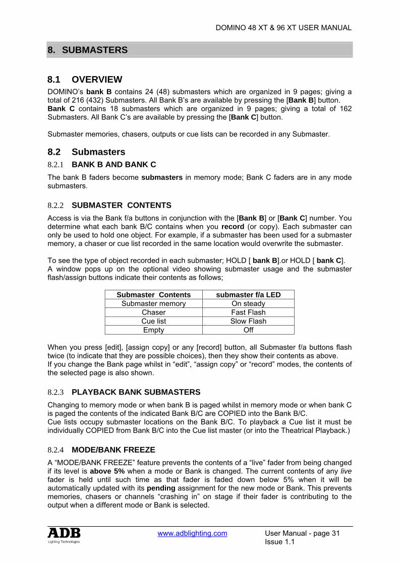
DOMINO 48 XT & 96 XT USER MANUAL
www.adblighting.com User Manual - page 31
Issue 1.1
8. SUBMASTERS
8.1 OVERVIEW DOMINO’s bank B contains 24 (48) submasters which are organized in 9 pages; giving a total of 216 (432) Submasters. All Bank B’s are available by pressing the [Bank B] button. Bank C contains 18 submasters which are organized in 9 pages; giving a total of 162 Submasters. All Bank C’s are available by pressing the [Bank C] button. Submaster memories, chasers, outputs or cue lists can be recorded in any Submaster.
8.2 Submasters 8.2.1 BANK B AND BANK C The bank B faders become submasters in memory mode; Bank C faders are in any mode submasters. 8.2.2 SUBMASTER CONTENTS Access is via the Bank f/a buttons in conjunction with the [Bank B] or [Bank C] number. You determine what each bank B/C contains when you record (or copy). Each submaster can only be used to hold one object. For example, if a submaster has been used for a submaster memory, a chaser or cue list recorded in the same location would overwrite the submaster. To see the type of object recorded in each submaster; HOLD [ bank B].or HOLD [ bank C]. A window pops up on the optional video showing submaster usage and the submaster flash/assign buttons indicate their contents as follows;
Submaster Contents submaster f/a LED Submaster memory On steady
Chaser Fast Flash Cue list Slow Flash Empty Off
When you press [edit], [assign copy] or any [record] button, all Submaster f/a buttons flash twice (to indicate that they are possible choices), then they show their contents as above. If you change the Bank page whilst in “edit”, “assign copy” or “record” modes, the contents of the selected page is also shown. 8.2.3 PLAYBACK BANK SUBMASTERS Changing to memory mode or when bank B is paged whilst in memory mode or when bank C is paged the contents of the indicated Bank B/C are COPIED into the Bank B/C. Cue lists occupy submaster locations on the Bank B/C. To playback a Cue list it must be individually COPIED from Bank B/C into the Cue list master (or into the Theatrical Playback.) 8.2.4 MODE/BANK FREEZE A “MODE/BANK FREEZE” feature prevents the contents of a “live” fader from being changed if its level is above 5% when a mode or Bank is changed. The current contents of any live fader is held until such time as that fader is faded down below 5% when it will be automatically updated with its pending assignment for the new mode or Bank. This prevents memories, chasers or channels “crashing in” on stage if their fader is contributing to the output when a different mode or Bank is selected.
DOMINO 48 XT & 96 XT USER MANUAL
www.adblighting.com User Manual - page 32
Issue 1.1
Whenever there is a pending memory chaser or channel change due to a 'Mode or Bank freeze', the “LED” indicator in the “mode” button will flash. This acts as a warning to you that the contents of on a submaster may change after it is faded down. The optional video screen also shows the current bank B number loaded on each submaster. 8.2.5 RECORD BANK SUBMASTERS During recording, storing, editing or copying, you can directly access any of the submaster on any Bank by using the [bank B] or [bank C] and [f/a] buttons. Changing Bank B/C numbers when recording, editing or copying does not affect the current contents of a submaster. If you attempt to record, store or copy over an existing content of a submaster a warning will appear on the display. To overwrite the content of a submaster either press [yes] or press the locations [f/a] button a second time. To pick a different submaster press [BANK B] or [Bank C] (optional), [f/a] (new location). 8.2.6 SELECT BANK SUBMASTERS When [select], [f/a] is pressed, the copy of a submaster memory or chaser in a submaster can be varied without affecting the original content of the submaster. When [select] is de-selected, the changes are retained in the submaster until a new submaster memory is loaded onto the submaster by a Bank B number change or a copy operation. To reload the original submaster memory into a submaster press; [copy], [f/a] (to same) [f/a]. 8.2.7 EDIT BANK SUBMASTERS When [edit], [f/a] is pressed, the copy of a submaster memory or chaser in a submaster and the original memory are edited. When [edit], [Bank B] or [Bank C], [f/a] is pressed, if the Bank you select is not currently loaded on a submaster, the original memory can be edited.
DOMINO 48 XT & 96 XT USER MANUAL
www.adblighting.com User Manual - page 33
Issue 1.1
9. SUBMASTER MEMORY
9.1 OVERVIEW A Submaster Memory is a recorded snapshot of the DOMINO output, together with In and Out fade time settings and a descriptive name. Submaster Memories are recorded in a submaster Submaster Memory fade times may come from the speed rotating fader or may be recorded in submaster memory. Individual IN, and OUT fade times may be recorded for every submaster memory.
Note: The DOMINO will not record a Submaster memory if all channels are at zero level.
9.2 RECORDING Submaster MEMORIES To record a submaster memory, create the desired look on the output, then press [record memory]. The Record memory button flashes and the display scrolls “Pick memory Number”. The Bank B button and the Function button flash to show that they are active. All Submasters will flash twice to indicate possible location choices, then Submasters already containing memories in that Bank B number will light. (Submasters containing chasers flash quickly, cue lists flash slowly and empty playbacks are not lit.) If the selected submaster location has already been used, the display will read “WARNING memory exists – overwrite?” You now have two options.
• To erase the existing submaster memory and replace it with the current output either press [yes] or [f/a] (existing submaster memory to overwrite).
• To pick another submaster memory location press [f/a] (new submaster memory location).
9.2.1 BANK SELECTION Repeated presses of either [Bank B] or [Bank C] button will cycle through the 9 Bank B/C numbers. To switch directly to a Bank B/C; HOLD [Bank B(C)], tap [f/a] (Bank B/C number). As you select each page, all Submasters will flash twice then indicate their contents as above. When a page is selected, if you HOLD the [Bank B] or [Bank C] button, a window pops up on the optional video screen showing you the contents and name of every submaster memory location. 9.2.2 NAMING A SUBMASTER MEMORY Each submaster memory is by default given its Bank number. Example: Number: B1:01 (Bank B, Bank B number1, Bank B fader 1) To enter or change a name; HOLD [function], tap [f/a] (name). The display says “Pick Object to Name” Press [BANK B(C)] (optional), [f/a] (submaster memory number). Either rotate the EDIT wheel or press the Bank A [f/a] buttons for the desired characters or the Bank B [f/a] buttons for numbers 1 to 10 (0) as labelled below the buttons. Where several characters are printed below each button, multiple presses select the next character in a similar fashion to a mobile telephone keypad. Press [<] or [>] to move the cursor and press [remove] or [add] to remove or add characters or spaces. Names may be up to 15 characters long. When finished, press [ok].
DOMINO 48 XT & 96 XT USER MANUAL
www.adblighting.com User Manual - page 34
Issue 1.1
9.2.3 SUBMASTER MEMORY PLAYBACK IN SUBMASTERS When you set the Mode to “memory”, the Bank B content in the current page is copied, in order, to their respective Submasters. If you change Bank B/C number, the Bank B/C content in the selected number is copied, in order, to their respective Submasters. 9.2.4 CONTROLLING A SUBMASTER MEMORY IN A SUBMASTER To reveal a submaster memory recorded on a submaster on the output, press [mode] until its “memory” LED lights. If necessary, select the page containing the submaster memory using the [Bank B(C)] button The memories can be faded in or out as required or they may be “Flashed” (soloed or bumped) via their [f/a] buttons. 9.2.5 FADE TIMES To control the fade times of the submaster memory in submaster you can either use the submaster memory time or the submaster time. “Select” allows you to change the in and out fade times in the submaster without affecting the original submaster memory. Press [Select], [f/a] (submaster), [function]. The “in” indicator lights. The display prompts you then shows the IN fade time. The fade time may be changed by rotating the EDIT wheel. When a time is set lower than 0 seconds, it is controlled by the rotating speed fader. Press [function] until the “out” indicator lights. The display prompts you then shows the OUT fade time. The fade time may be changed by rotating the EDIT wheel. When a time is set lower than 0 seconds, it is controlled by the rotating speed fader. When you have finished adjusting the times, press [Select]. The changes that you have made are retained in the submaster until such time as the submaster memory is replaced on that submaster (by changing Bank B or mode). To restore the original submaster memory to the submaster press [copy], [f/a] to the same [f/a]. “Edit” allow you to directly change the submaster memory settings. In addition to changing the fade times you can edit the channel levels of the submaster memory. These changes are automatically saved as you edit. If the submaster memory is currently on a submaster, then these changes are also seen live on that submaster. Edit is described below. 9.2.6 EDITING IN A SUBMASTER You may edit a submaster memory live or blind (faded down) on its submaster. If the submaster memory is faded up on stage you will see the changes. When you edit the submaster memory its channel levels are shown on LED indicators and on the optional VGA monitor. The LEDs intensity reflects the levels of those channels in the memory. • To edit a submaster memory on a submaster, press; [edit], [f/a] (submaster). • To edit a submaster memory (in the Grab master), press; [edit], [f/a] (Grab master) • To edit a submaster memory in a different Bank B, press; [edit], [Bank B], [f/a]
(submaster). The FUNCTION button flashes to show that it is active. It allows you to read and edit actual channel levels and fade times for the submaster memory (see below). Repeated presses of [function] will cycle the display through channel LEVEL(%), IN time setting, OUT time setting and the Bank B number. These editing processes are described below.
DOMINO 48 XT & 96 XT USER MANUAL
www.adblighting.com User Manual - page 35
Issue 1.1
9.2.7 CHANNEL LEVELS To read and/or edit the level of any channel in a submaster memory, edit the submaster memory (above) then press a channels [f/a] button. Whilst the f/a button is held down, the display shows the channel number. When the f/a button is released, the display shows the level of that channel in the submaster memory. To edit the level of the selected channel, rotate the EDIT wheel. If the level is varied above its recorded value it is prefixed by a + sign. When a parameter is varied below its recorded value it is prefixed by a - sign. If the level is restored to its original value no sign is shown. Press and release further channel [f/a] buttons to read and/or edit their levels. When finished editing press [edit]. All changes are automatically saved. 9.2.8 FADE TIMES To read and/or edit the IN or OUT fade times in a submaster memory, edit the submaster memory as described above then use the function button to select each time IN TIME Repeatedly press [function] until the “in” indicator lights. The display prompts you then shows the IN fade time. The fade time may be edited by rotating the EDIT wheel. When a time is set lower than 0 seconds, it is controlled by the rotating speed fader. OUT TIME Repeatedly press [function] until the “out” indicator lights. The display prompts you then shows the OUT fade time. The fade time may be edited by rotating the EDIT wheel. When a time is set lower than 0 seconds, it is controlled by the rotating speed fader. Any changes that you have made will automatically be saved in submaster memory. 9.2.9 EDITING A SUBMASTER MEMORY NAME Names are edited in the same way as they are recorded, not from edit mode. See “NAMING A SUBMASTER MEMORY” above for details. 9.2.10 COPYING A SUBMASTER MEMORY To copy a submaster memory, press [assign/copy]. The display reads “Pick memory to copy from”. If the source is not in the current page, use the [Bank B(C)] to select the source page number. Press [f/a] of the source submaster memory number, the display will briefly read, “Pick location to copy to”. submasters containing memories are lit. Submasters containing chasers flash rapidly. Submasters containing Cue Lists flash slowly. Empty submasters are not lit. This acts as a warning to you of existing submaster memory, cue list and chaser numbers in each page of submasters. If the destination is not in the current page, use the [Bank B(C)] button to select the destination page number. Press [f/a] of the destination submaster memory number. If the selected submaster location has already been used, the display will read “WARNING memory exists – overwrite?”. You now have two options.
• To erase the existing submaster memory and replace it with the copy either press [yes] or [f/a] (existing submaster memory to overwrite).
• To pick another submaster location press [f/a]
DOMINO 48 XT & 96 XT USER MANUAL
www.adblighting.com User Manual - page 36
Issue 1.1
The copy process may be abandoned at any time prior to entering the destination submaster memory number by pressing [assign/copy] a second time.
Hint; In a show or performance, the transition from one submaster memory to the next will sometimes only involve a change of a few channels. The majority of channels will remain the same. If this is the case, it is quickest to make a copy of the first submaster memory and then edit the copy to create the next memory. This method ensures that any channels that are to be the same in both memories will have identical levels.
9.2.11 REMOVING (DELETING) A S SUBMASTER MEMORY To remove (delete) a submaster memory from submaster, press [remove]. If required, repeatedly press either [Bank B(C)] button until the required page number is displayed, then press [f/a] of the submaster memory to be removed. The display asks you to confirm your action. Press [yes].
DOMINO 48 XT & 96 XT USER MANUAL
www.adblighting.com User Manual - page 37
Issue 1.1
10. TIMES
10.1 OVERVIEW Individual IN (up) and OUT (down) fade times may be recorded for every theatrical memory, submaster memory and every step in a cue list. The times may range from 0 seconds up to 16 minutes 39 seconds (999 seconds).The Up and Down times can be the same or can have different values. If no times are entered by the operator when recording a theatrical memory, submaster memory the default times are used. The default times can, of course, be changed to suit the operator’s preference if a different time is preferred. This setting is described in the Utilities section. 10.1.1 UP TIME (IN) The up time is the time that applies to channels that are increasing in intensity, or “incoming”. In the playback, transitions are made by the contents of Preset replacing the contents of Stage. The up time is therefore applied to channels that have a higher intensity in the Preset than they do in Stage. The up time for submaster is the time taken for the virtual fader to be raised from zero. 10.1.2 DOWN TIME (OUT) The down time is the time that applies to channels that are decreasing in intensity, or “outgoing”. In the playbacks, transitions are made by the contents of Preset replacing the contents of Stage. The down time is therefore applied to channels that have a lower intensity in the Preset than they do in Stage. The down time of an Auto submaster is the time taken for the virtual fader value to reach zero.
10.2 SUBMASTER TIMES When a Submaster contains a submaster memory, it’s In and Out fade times may be changed. Pressing [edit], [f/a] (Submaster memory in submaster to change), pressing [function] until the “in” LED lights. The IN fade time may be set by rotating the EDIT wheel. When a time is set lower than 0 seconds, it is controlled by the speed rotating fader. Press [function]. The “out” LED lights. The OUT fade time may be set by rotating the EDIT wheel. When a time is set lower than 0 seconds, it is controlled by the speed rotating fader. To record the process, press [edit]. 10.2.1 SPEED ROTATING FADER The speed rotating fader allows direct speed control correction at any time while the fade is running. By turning it to the right, you accelerate; turning it to the left, slow down. 10.2.2 SUBMASTER TIME DIFFERENT THAN SUBMASTER MEMORY TIME –
SELECT FUNCTION When a Submaster contains a submaster memory, the submaster in and Out fade times may be different of the submaster memory times. Pressing [select], [f/a] (submaster to change), [function] allows you to change the in time and out time on the selected submaster . The “in” LED lights. The IN fade time may be set by rotating the EDIT wheel. When a time is set lower than 0 seconds, it is controlled by the speed fader. Press [function]. The “out” LED lights. The OUT fade time may be set by rotating the EDIT wheel. When a time is set lower than 0 seconds, it is controlled by the speed fader. To end the process, press [select].
DOMINO 48 XT & 96 XT USER MANUAL
www.adblighting.com User Manual - page 38
Issue 1.1
When you have finished adjusting the time, the original submaster memory is not affected, but the changes that you have made are retained in the submaster until such time as the submaster memory is replaced on that submaster (by changing Bank B or Mode).
10.3 THEATRICAL MEMORY TIMES In and Out fade times of Theatrical memory may be changed. Pressing [edit], last used memory number appear, use wheel to select memory number, pressing [OK] (Memory in Memory List to change), pressing [function] until the “in” LED lights. The IN fade time may be set by rotating the EDIT wheel. When a time is set lower than 0 seconds, it is controlled by the speed fader. Press [function]. The “out” LED lights. The OUT fade time may be set by rotating the EDIT wheel. When a time is set lower than 0 seconds, it is controlled by the speed fader. To record the process, press [edit].
10.4 CHASERS TIMES When a Submaster contains a Chaser, its overall level fade times are controlled manually by the movement of the submaster fader. The transitions between steps of a chaser may be instantaneous (snaps) or crossfades. See the “Chaser” section for details.
10.5 CUE LISTS TIMES When a Cue List is assigned to the Cue List master, the times of the crossfade from one step to the next are determined by the settings that have been recorded for each step. See the “Cue List” section for details

DOMINO 48 XT & 96 XT USER MANUAL
www.adblighting.com User Manual - page 39
Issue 1.1
11. CHASERS
11.1 OVERVIEW A chaser is a recorded list of steps that are to be replayed in order, stepping continuously from one step to the next and automatically repeating the list when it has reached the end. Each step in a chaser can consist of a previously recorded submaster memory or a snapshot of the output (which is taken when that step is added to the chaser). Up to 250 steps may be recorded for each chaser. The chaser stepping can be controlled by an audio input or by a beat pattern that you teach the DOMINO. See the “STL and SyncoBEAT” section for details. Chasers are recorded by page/chaser number. Page numbers are selected with the [Bank B] button and chaser numbers are selected with the submaster [f/a] buttons. Chaser mode, speed in BPM (Beats Per Minute) and crossfade times are recorded in submaster as part of each chaser.
11.2 CHASER TERMINOLOGY 11.2.1 BOUNCE The chaser automatically changes direction when it reaches the last or first step. In this manner, it continuously “bounces” from end to end. 11.2.2 SINGLE SHOT The chaser is normally stopped. When it is started, it will run through its recorded steps once in the direction in which it is started. It will then stop and wait until it is manually started again in either direction. 11.2.3 CHASER CROSSFADE Traditionally chasers will snap (instantly switch) from step to step but in the DOMINO you may also set a crossfade value so that it will fade from step to step. The Crossfade is set as a percentage of the chaser speed. For example, if the chaser speed is set at 60 BPM (which is one step per second), then with crossfade set at 0% (that is, no fade), the chaser will wait for one second, then snap to the next step. None (0%) of the available speed time will be used for crossfading. If the crossfade is set to 50%, then the chaser will perform a 0.5 second crossfade to the next step, wait for 0.5 seconds and then perform the next crossfade. That is, 50% of the time is used to perform a crossfade and 50% of the time is spent waiting before starting the next crossfade. If the crossfade is set to 100%, then the Chaser will use all of the time performing a crossfade to the next step. When the crossfade is complete, the next crossfade will commence immediately
11.3 CHASER RECORDING To record a chaser, press; [record chaser], Select a submaster memory number for the chaser, press; [Bank B] (optional), [f/a] (submaster) Each step of a chaser consists of a either a previously recorded submaster memory or a snapshot.
• To select a submaster memory as a step, press; [Bank B] (optional),[f/a] • To record a snapshot (of the current output) as a step, press;[record memory].
Continue to record steps as above. You may mix snapshots or memories in any order. When all steps have been recorded, complete the chaser by pressing;[record chaser].
DOMINO 48 XT & 96 XT USER MANUAL
www.adblighting.com User Manual - page 40
Issue 1.1
11.3.1 REMOVING STEPS Whilst recording (above), if the step that you add is not correct, the last step may be deleted by pressing [remove]. 11.3.2 CHASER SPEED At any point after giving the chaser a submaster (above), repeated presses of [function] will toggle the display between the STEP number, the SPEED in BPM (Beats Per Minute) and the CROSSFADE percentage. When the SPEED is displayed, the EDIT wheel may be used to set the desired speed. The default setting is 100 BPM but you may change this in the “Setup Preferences”. See the “UTILITIES” section. 11.3.3 CHASER CROSSFADE At any point after giving the chaser a submaster, repeated presses of the [function] button will toggle the display between the STEP number, the SPEED setting in BPM (Beats Per Minute) and the CROSSAFDE percentage. When the IN & OUT indicators are lit, the EDIT wheel may be used to set the percentage of the chaser speed time that is used for the crossfade. The default setting is 0% (no crossfade) but you may change this in the “Setup Preferences”. 11.3.4 COMPLETING THE CHASER When all steps have been recorded, and the speed and crossfade have been set, complete the chaser by pressing [record chaser]. The chaser will be a conventional forward running chase. To select other chaser modes either [select] or [edit] the chaser as described below.
11.4 NAMING A CHASER Each chaser is by default given its Bank B, page and f/a number as a name. For example, B1:02 (bank B, page 1, chase 2). To enter or change a name, HOLD [function], tap [f/a] (name) (bank A f/a button). The display says “Pick Object to Name”. Press [page] (optional) [f/a] (submaster memory number). Either rotate the EDIT wheel or press the [f/a] buttons for the desired characters or the bank [f/a] buttons for numbers 1 to10 (0) as labelled below the buttons. Where several characters are printed below each button, multiple presses select the next character in a similar fashion to a mobile telephone keypad. Press [<] or [>] to move the cursor and press [remove] or [add] to remove or add characters or spaces. When finished, press [ok].
11.5 CHASER PLAYBACK Chasers may be replayed on the:
• Submasters • Grab master. • As a step in a Cue list.]
11.5.1 SUBMASTERS When you set the mode to “memory”, the chasers (and memories) in the current page are copied, in order, to their respective submasters. If you change pages, the chasers (and memories) in the selected page are copied, in order, to their respective submasters.
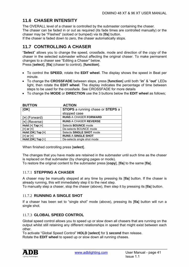
DOMINO 48 XT & 96 XT USER MANUAL
www.adblighting.com User Manual - page 41
Issue 1.1
11.6 CHASER INTENSITY The OVERALL level of a chaser is controlled by the submaster containing the chaser. The chaser can be faded in or out as required (its fade times are controlled manually) or the chaser may be “Flashed” (soloed or bumped) via its [f/a] button. If the chaser is faded down to zero, the chaser automatically stops.
11.7 CONTROLLING A CHASER “Select” allows you to change the speed, crossfade, mode and direction of the copy of the chaser in the selected submaster without affecting the original chaser. To make permanent changes to a chaser see “Editing a Chaser” below. Press [select], [f/a] (chaser to control), [function]. • To control the SPEED, rotate the EDIT wheel. The display shows the speed in Beat per
minute. • To change the CROSSFADE between steps, press [function] until both “in” & “out” LEDs
light, then rotate the EDIT wheel. The display indicates the percentage of time between steps to be used for the crossfade. See CROSSFADE for more details
• To change the MODE or DIRECTION use the 3 buttons below the EDIT wheel as follows;
BUTTON ACTION [OK] STOPS a running chase or STEPS a
stopped case [>] (Forward) RUNS A CHASER FORWARD[<] (Reverse) RUNS A CHASER REVERSEHold [>] Tap [<] Selects BOUNCE mode[>] or [<] De-selects BOUNCE modeHold [OK] Tap [>] Selects SINGLE SHOT mode[>] or [<] RUNS A SINGLE SHOT Hold [OK] Tap [>] De-selects single shot mode When finished controlling press [select]. The changes that you have made are retained in the submaster until such time as the chaser is replaced on that submaster (by changing pages or mode). To restore the original content to the submaster press [copy], [f/a] to the same [f/a]. 11.7.1 STEPPING A CHASER A chaser may be manually stepped at any time by pressing its [f/a] button. If the chaser is already running, this will immediately step it to the next step. To manually step a chaser, stop the chaser (above), then step it by pressing its [f/a] button. 11.7.2 RUNNING A SINGLE SHOT If a chaser has been set to “single shot” mode (above), pressing its [f/a] button will run a single shot. 11.7.3 GLOBAL SPEED CONTROL Global speed control allows you to speed up or slow down all chasers that are running on the output whilst still retaining any different relationships in speed that might exist between each other. To activate “Global Speed Control” HOLD [select] for 1 second then release. Rotate the EDIT wheel to speed up or slow down all running chases.

DOMINO 48 XT & 96 XT USER MANUAL
www.adblighting.com User Manual - page 42
Issue 1.1
The speed can be increased by up to 1999% of its original value. The minimum speed is limited to 999 BPM. The speed can be decreased to 0% of its original speed. For example:
• A1.01 has a recorded speed or 120BPM and its fader is at 100%. • A1.02 has a recorded speed or 200BPM and its fader is at 0%. • A1.03 has a recorded speed or 60BPM and its fader is at 10%.
Hold down [select] for 1 second to activate “Global Speed Control”. This will assign A1.01 and A1.03 to Global Speed Control. Now fade up chaser A1.02. As it was not active when global speed was selected, it will not be affected when the global speed is varied Rotate the EDIT wheel until the display reads 50%.
• A1.01 is now running at 60 BPM. • A1.02 is still running at 200 BPM. • A1.03 is now running at 30 BPM
Rotate the EDIT wheel until the display reads 200%; • A1.01 is now running at 240 BPM. • A1.02 is still running at 200 BPM. • A1.03 is now running at 120 BPM
Tapping [function] resets all selected chasers to the “default” chaser speed as set in the “Setup”, “Preferences” menu. If the default is set to 100 BPM, then in this example, tapping [function] results in;
• A1.01 is now running at 100 BPM. • A1.02 is still running at 200 BPM. • A1.03 is now running at 100 BPM
Rotate the EDIT wheel until the display reads 150%;
• A1.01 is now running at 150 BPM. • A1.02 is still running at 200 BPM. • A1.03 is now running at 150 BPM
To exit Global Speed press [select]. All chasers remain at their modified speed. The original speed of the chaser can be restored by copying the chaser back into the submaster. Press [copy], [f/a], to the same [f/a].
11.8 EDITING A CHASER “Edit” allows you to permanently change the speed, crossfade, mode and direction plus you can add or delete steps, connect or disconnect the STL (Sound to Light) processors and edit the contents of each step. These changes are applied to the chaser and if the chaser is currently on a submaster, they will also be applied to the submaster. If the chaser is faded up on stage you will see the changes. If the chaser is not live on stage, its steps are displayed on the channel LED indicators and on the optional SVGA monitor. • To edit a chaser on a submaster, press;[edit], [f/a]. • To edit a chaser in the Grab master, press; [edit], [f/a] • To edit a chaser in a different page, press [edit], [Bank B] [f/a]

DOMINO 48 XT & 96 XT USER MANUAL
www.adblighting.com User Manual - page 43
Issue 1.1
The indicators in the channel f/a buttons show the channels of the running chaser. Their intensity reflects the levels of the channels in each step. • To control the SPEED, rotate the EDIT wheel. • To change the CROSSFADE between steps, press [function] until both “in” & “out” LEDs
light, then rotate the EDIT wheel. • To change the MODE or DIRECTION, use the 3 buttons below the EDIT wheel as
described above.
• To connect or disconnect a STL (Sound To Light or SyncoBEAT) from the chaser, repeatedly HOLD [function] until the STEP number(s) are shown on the display and the STL button LEDs flash. Whilst holding [function] tap either [STL1] or [STL2]. Press [yes] to connect or disconnect the selected STL. See the “STL and SyncoBEAT” section for more details.
11.8.1 ADD A STEP To add a step, first edit the chaser (above), then press [OK] to stop the chaser and continue pressing to step the chaser to the step prior to the point where the new step is to be added. Press [add] then either;
• Create the look for the new step on the output and press [record memory], or • To add a submaster memory as a step, press; [Bank B] (optional), [f/a] (memory
number), or If necessary press [>] or [<] to start the chaser again in the desired direction. When finished editing press [edit]. All changes are automatically saved. 11.8.2 REMOVE A STEP To remove a step, first edit the chaser (above), then press [OK] to stop the chaser and continue pressing to select the step to be removed. To remove the step, press [remove], [yes]. If necessary, press [>] or [<] to start the chaser again in the desired direction. When finished editing press [edit]. All changes are automatically saved. 11.8.3 MODIFY A STEP To modify the channel levels of a step, first edit the chaser (above), then press [OK] to stop the chaser and continue pressing to select the step to be modified. Press [function] until the “chan” LED indicator lights and the display reads; “Pick channel to edit”. To see the level of any channel, press its [f/a] (channel number) button. Whilst the channels f/a button is held down, the display shows the channel number. When the f/a button is released, the display shows the level of that channel in the step. To edit the level of the selected channel, rotate the EDIT wheel. If the level is varied above its recorded value it is prefixed by a + sign. If it is varied below its recorded value it is prefixed by a - sign. If the level is restored to its original value no sign is shown. Press and release further channel [f/a] buttons to read and/or edit their levels.
Note: If the chaser step that you modify is a submaster memory, then that actual submaster memory is edited, not just the chase step. If you directly edit a submaster memory and that submaster memory is a step in a chase, then the changes will be seen in the chaser.
DOMINO 48 XT & 96 XT USER MANUAL
www.adblighting.com User Manual - page 44
Issue 1.1
To modify other steps, press [OK] to step the chaser then again select any channels to be modified with their f/a buttons. If necessary press [>] or [<] to start the chaser again in the desired direction. When finished editing press [edit]. All changes are automatically saved. 11.8.4 EDITING A CHASER NAME Names are edited in the same way as they are recorded, not from edit mode. See “NAMING A CHASER” above for details.
11.9 COPYING A CHASER To copy a chaser, press; [assign/copy]. [Bank B] [f/a] [Bank B] [f/a] If the selected submaster memory location has already been used, the display will read “WARNING submaster exists – overwrite?”. You now have two options.
• To erase the existing submaster and replace it with the copy either press [yes] or [f/a] (existing submaster to overwrite).
• To pick another submaster press [f/a] (new submaster memory location). The copy process may be abandoned at any time prior to entering the destination submaster by pressing [assign/copy] a second time. That is, de-selecting it.
Hint: If you have recorded a chaser and you want to experiment with some changes, make a copy of the chaser and edit the copy. In the event that your changes are unsatisfactory, the original remains unaltered.
11.10 REMOVING A CHASER To remove (delete) a chaser from a submaster, press [remove]. If required, repeatedly press [page] until the required page number is displayed, then press [f/a] of the chaser to be removed. The display asks you to confirm your action. Press [yes].

DOMINO 48 XT & 96 XT USER MANUAL
www.adblighting.com User Manual - page 45
Issue 1.1
12. CUE LIST
12.1 OVERVIEW A CUE LIST is a recorded list of steps that are to be replayed in order. Each step consists of either a submaster memory, a chaser or a snapshot of the output (which is taken when that step is added). Stepping from one step to the next is a Dipless Crossfade and is usually executed manually but can be automatic. Each Cue list and each step can be named.
Up to 500 steps may be recorded in each cue list and up to 108 (216) separate cue lists may be recorded into submaster memory. If all the lighting cues in a "show" have been recorded into a "cue list", then the entire show may be performed on the cue list master by simply pressing the forward " > " button for each lighting cue.
Cue lists are recorded by page/cue list number. Page numbers are selected with the [Bank B] button and cue list numbers are selected with the [f/a] buttons. Cue lists may be randomly recorded into any page, f/a number, however memories, chasers and cue lists use the same submaster locations. A cue list recorded in a previously used submaster will overwrite the previous contents.
Cue lists may only be replayed on the Cue list Master, which provides comprehensive facilities to control the replay of the Cue list. Crossfade times for each step are recorded into cue list or can be under control of the rotating speed fader. Each step can be given a “link“ time causing it to automatically step after an elapsed link time.
A cue list may be edited. The contents of any step may be changed; the fade and link times varied and steps may be inserted or deleted. A cue list may be copied onto another page/ f/a number or onto or from the Grab master.
12.2 RECORDING A CUE LIST To record a cue list, press; [record cue list], [Bank B(C)] (optional), [f/a] (cue list number) (any f/a). Adding steps: • To select a submaster memory as a step press; [Bank B(C)] (optional), [f/a] (submaster
memory). • To select a chaser as a step press; [Bank B(C)] (optional), [f/a] (chaser). • To record a snapshot (of the current output) as a step press; [record submaster
memory]. A blackout can be recorded as a step • To add a range of submasters (memories and or chasers) select the [Bank B(C)]
(optional) then HOLD [f/a] (first submaster in range), and tap [f/a] (last submaster in range). Any submaster memory in the selected range that is empty or contains a cue list will be ignored
Continue to add steps. You may mix snapshots, chasers or memories in any order. When all steps have been added, complete the cue list by pressing; [record cue list]. 12.2.1 REMOVING STEPS Whilst recording the cue list (above), the last step may be deleted by pressing; [remove]. 12.2.2 FADE AND LINK TIMES As each step is added (above) you may set the fade IN, OUT and LINK times (automatically links to next step after link time expires) for that step.
After each step has been added, repeatedly press [function] to cycle through the fade IN time, fade OUT time and LINK time. When any of the time settings are indicated, rotate the EDIT wheel to set the desired time.
DOMINO 48 XT & 96 XT USER MANUAL
www.adblighting.com User Manual - page 46
Issue 1.1
The minimum time is more than 16 minutes and the minimum time is 0 seconds. When a time is set lower than 0 seconds, it reverts to rotating speed fader. If you do not enter a time then the default settings will be used. The default step times are; • SUBMASTER MEMORY = the fade times from that SUBMASTER MEMORY. • LINK = No link. • SNAPSHOT = rotating speed fader. (You can change the default times with the “Setup Preferences” function. See the “UTILITIES” section).
See REPLAYNG CUE LISTS below for more details on fade and link times.
12.3 NAMING A CUE LIST Each cue list is by default given its Bank B(C) and f/a number as a name. For example, b1:03 (Bank B, page 1, cue list 3). To enter or change a name, HOLD [function], tap [f/a] (name). The display says “Pick Object to Name”. Press [] (optional) [f/a] (cue list number) Either rotate the EDIT wheel or press the channel A [f/a] buttons for the desired characters or the bank B(C) [f/a] buttons for numbers 1 to10 (0) as labelled below the buttons. Where several characters are printed below each button, multiple presses select the next character in a similar fashion to a mobile telephone keypad. Press [<] or [>] to move the cursor and press [remove] or [add] to remove or add characters or spaces. When finished, press [ok]. 12.3.1 NAMING EACH STEP IN A CUE LIST See “EDITING A CUE LIST” below
12.4 CUE LIST PLAYBACK To playback a cue list, it must be copied from its submaster memory location to the cue list master. Press; [copy],[Bank B(C)] (optional),[f/a] (source cue list number),[cue list flash] Fade up the cue list master to reveal the first step. When a cue list is idle, its output comes from the current step. The step that will follow this step is called the next step. When a crossfade is initiated, the cue list master performs a Dipless Crossfade from the current step to the next step. When the cue list reaches the last step, it will wrap around to the start. 12.4.1 PLAYBACK OF THE THEATRICAL MEMORY LIST Not implemented at writing of manual 12.4.2 CUE LIST INTENSITY LEVEL The OVERALL output level of a cue list is controlled by the cue list master. The cue list can be manually faded in or out as required or the cue list may be flashed via its [cue list flash] button. 12.4.3 CUE LIST VIDEO To see a comprehensive display of the status of the cue list on the optional video output, HOLD [function], tap [f/a] (video 3). 12.4.4 STARTING A CROSSFADE To crossfade from the current step to the next step, press; [ >] (forward).
DOMINO 48 XT & 96 XT USER MANUAL
www.adblighting.com User Manual - page 47
Issue 1.1
The crossfade will occur with the incoming step fading in; in it’s IN time and the outgoing step fading out in its OUT time. The display momentarily shows the step number of the incoming step. To momentarily see the step number again, hold down [OK] (cue list master). To continuously see the step number on the display press [select], [cue list flash]. To turn off the display press [select]. While the crossfade is in progress, the > (forward) button flashes for the duration of the IN fade and the < (reverse) button flashes for the duration of the OUT fade. Each press of the [>] (forward) button will start the crossfade to the next step. Note: You do not have to wait for a step to complete before starting the next step.
12.4.5 CROSSFADING TO THE PREVIOUS STEP To crossfade from the current step to the previous step, press; [<] (reverse). You may only crossfade back one step. You may however STEP back to any step. See “STEPPING A CUE LIST” below 12.4.6 STOPPING A CROSSFADE To stop a crossfade in progress press; [OK]. When a crossfade has been stopped, the > (forward) button, < (reverse) button and OK buttons all flash. 12.4.7 STARTING A STOPPED CROSSFADE To start a stopped crossfade in the forward direction, press; [>] (forward). To start a stopped crossfade in the reverse direction, press; [<] (reverse). To momentarily run a stopped crossfade in the current direction; HOLD [OK]. The crossfade only progresses whilst [stop/step] is held down. 12.4.8 REVERSING A CROSSFADE To reverse a crossfade in progress and return to the previous step, press; [<] (reverse). 12.4.9 STEPPING A CUE LIST If a cue list is stationary (idle between steps), you may step (instant change, no times executed) through the cue list in either direction. To instantly step a cue list in the forward direction; HOLD [OK], tap [>] (forward). To instantly step a cue list in the reverse direction; HOLD [OK],tap [<] (reverse). 12.4.10 RANDOM STEP SELECTION To randomly jump to any step in a cue list; HOLD [OK] and rotate the EDIT Wheel. The display shows the selected step number. A + or – sign indicates that the selected step is higher or lower than the current step. The current step has no sign. When the [stop/step] button is released, the cue list jumps to the selected step.

DOMINO 48 XT & 96 XT USER MANUAL
www.adblighting.com User Manual - page 48
Issue 1.1
12.5 CUE LIST TIMES 12.5.1 FADE TIMES The times of the crossfade from one step to the next are determined by the settings that have been recorded for each step. This can be the manual with the rotating speed fader as well as a set time. The transition from one step to the next is in the form of a DIPLESS CROSSFADE. The incoming step will fade up in the IN time for that step and the outgoing step will fade down in the OUT time for that step. 12.5.2 LINK TIMES If a step contains a LINK time, then when that step is played, its link time starts counting down. At the completion of the link time, the cue list will automatically step to the next step. If every step has a link time, then the cue list will play like a chase, but with the following differences.
• The duration of every step may be individually set by its link time. • The in and out fade times of every step may be individually set. • A step may be a chaser.
This allows you to create very complex and interesting chasers. Hint: If you need a link time in every step of a cue list (to make it chaser) it is much quicker to set the default link time using the preference function rather than setting every individual step. See the “UTILITIES” section for details.
12.6 EDITING A CUE LIST You may edit a cue list live or blind (faded down) on the cue list master or directly in its submaster memory location. If the cue list is faded up on stage you will see the changes. If the cue list is not live on stage, its steps are displayed on the channel LED indicators and on the video monitor. You can add or delete steps, change fade and link times and edit the contents of each step (including channels not already on in the step). • To edit the cue list on the cue list master, press; [edit], [cue list flash]. • To edit a cue list in submaster memory, press; [edit], [Bank B(C)] (optional),
[f/a] (cue list number)
The display momentarily shows the Bank B(C)/page/cue list number or name and then it shows step number and its contents. If you edit the cue list on the cue list master, the current step will be selected. If you edit a cue list in submaster memory, step 1 will be selected. Step through the cue list using the [<] or [>] buttons below the EDIT wheel. The indicators in the channel F/A buttons show the channel levels in each step. The [function], [remove] and [add] buttons also flash to show that they are active. Their uses are described below. When finished editing, press [edit]. Changes are automatically saved. 12.6.1 ADD A STEP To add a step to a cue list, first edit the cue list (above) then step through the cue list using the [<] or [>] buttons below the EDIT wheel. Select the step after which the new step is to be inserted, then press [add]. • To select a submaster memory as the added step, press; [Bank B(C)] (optional), [f/a]
(submaster memory). • To record a snapshot (of the current output) as the added step press; [record submaster
memory]. To select a chaser as the added step, press; [Bank B(C)] (optional), [f/a] (chaser).
DOMINO 48 XT & 96 XT USER MANUAL
www.adblighting.com User Manual - page 49
Issue 1.1
When finished editing, press [edit]. Changes are automatically saved. 12.6.2 REMOVE A STEP To remove a step from a cue list, first edit the cue list (above) then step through the cue list using the [<] or [>] buttons below the EDIT wheel. Select the step that is to be deleted, then press [remove], [yes]. When finished editing, press [edit]. Changes are automatically saved. 12.6.3 EDIT THE TIMES OF A STEP To edit the times of a step in a cue list, first edit the cue list (above) then step through the cue list using the [<] or [>] buttons below the EDIT wheel to select the step to be edited. • To edit the IN time, press [function] until the “in” LED lights. The display prompts you
then shows the IN fade time. The fade time may be edited by rotating the EDIT wheel. When a time is set lower than 0 seconds, it is controlled by the rotating speed fader.
• To edit the OUT time, press [function] until the “out” LED lights. The display prompts you then shows the OUT fade time. The fade time may be edited by rotating the EDIT wheel. When a time is set lower than 0 seconds, it is controlled by the rotating speed fader.
• To edit the LINK time, press [function] until the “in” and “out” LED lights. Use the EDIT wheel to set the “link” time. A link time causes the cue list to automatically step to the next step after link time expires.
When finished editing, press [edit]. Changes are automatically saved. 12.6.4 EDIT THE CHANNELS LEVELS OF A STEP If the step is a snapshot or a submaster memory you can edit the channel levels of the step.
Note: If the step that you are editing is a submaster memory, the channel levels in the original submaster memory are edited, not just the step. Likewise, if you edit the actual submaster memory, the changes will also be seen in the step of the cue list that contains that submaster memory.
To edit the channel levels of a step in a cue list, first edit the cue list (above) then step through the cue list using the [<] or [>] buttons below the EDIT wheel to select the step to be edited. Repeatedly press [function] until the “level” LED lights and the display reads “Pick Channel to edit”. To see the level of any channel, press its [f/a] button. Whilst the channels’ f/a button is held down, the display shows the channel number. When the f/a button is released, the display shows the level of that channel in the step. To edit the level of the selected channel, rotate the EDIT wheel. If the level is varied above its recorded value it is prefixed by a + sign. When a parameter is varied below its recorded value it is prefixed by a - sign. If the level is restored to its original value no sign is shown. Press and release further channel [f/a] buttons to read and/or edit their levels. When finished editing, press [edit]. Changes are automatically saved. 12.6.5 NAMING EACH STEP IN A CUE LIST To name a step in a cue list, first edit the cue list (above) then step through the cue list using the [<] or [>] buttons below the EDIT wheel to select the step to be named. The “step” LED is lit and the display scrolls the step number.
DOMINO 48 XT & 96 XT USER MANUAL
www.adblighting.com User Manual - page 50
Issue 1.1
HOLD [function], tap [f/a] (name), a channel A function button. The display says “Edit Step Name”. Either rotate the EDIT wheel or press the Bank B(C) [f/a] buttons for the desired characters or the channel B [f/a] buttons for numbers 1 to10 (0) as labelled below the buttons. Where several characters are printed below each button, multiple presses select the next character in a similar fashion to a mobile telephone keypad. Press [<] or [>] to move the cursor and press [remove] or [add] to remove or add characters or spaces. When finished, press [ok]. 12.6.6 ENDING EDIT Edit may be ended at any time by pressing [edit]. Any changes that you have made will automatically be saved in submaster memory. 12.6.7 EDITING A CUE LIST NAME Cue list names are edited in the same way as they are recorded, not from edit mode. See “NAMING A CUE LIST” above for details.
12.7 COPYING A CUE LIST To copy a cue list, press; [assign/copy].[Bank B(C)] (optional source page),[f/a] (source cue list number)[Bank B(C)] (optional destination page)[f/a] (destination cue list number).
Note: When you make a copy of a cue list, any cue list (or submaster memory or chaser) that is currently in the destination number will be overwritten by the copy.
If the selected submaster memory location has already been used, the display will read “WARNING submaster memory exists – overwrite?”. You now have two options.
• To erase the existing submaster memory and replace it with the copy either press [yes] or [f/a] (existing submaster memory to overwrite).
• To pick another submaster memory location press [f/a] (new submaster memory location).
The copy process may be abandoned at any time prior to entering the destination memory number by pressing [assign/copy] a second time. That is, de-selecting it.
Hint: If you have recorded a cue list and you want to experiment with some changes, make a copy of the cue list and edit the copy. In the event that your changes are unsatisfactory, the original remains unaltered.
12.8 REMOVING (DELETING) A CUE LIST To remove (delete) a cue list from submaster memory, press; [remove], [Bank B(C)], (optional), [f/a] (cue list number). The display asks you to confirm your action. Press [yes].
12.9 CLEARING THE CUE LIST MASTER To remove (clear) a cue list from the cue list master, press [remove], [cue list flash].
The display asks you to confirm your action. Press [yes]
DOMINO 48 XT & 96 XT USER MANUAL
www.adblighting.com User Manual - page 51
Issue 1.1
13. FLASH
13.1 OVERVIEW The FLASH section of the utilises the “f/a” (Flash/Assign) buttons in the fader Bank B(C) sections provide extensive flashing control. When a channel is “flashed” it can either “add” to the current output of the desk or it can be “solo” where it becomes the ONLY output You may Flash any channel, fixture or multiple channels or fixtures, any submaster, or any multiple combination of the above at the one time. The only limit is your ability to hold down multiple buttons. The Flash function is a momentary action. As soon as all Flash buttons are released, normal output is restored.
There are no times associated with the FLASH function. All actions are instantaneous.
13.2 ADD/SOLO MODE You may select what effect the Flash buttons have on the output, by selecting either ADD mode or SOLO mode. Pressing the [ADD/SOLO] button will toggle from one mode to the other. SOLO mode is indicated when LED in the ADD/SOLO button flashes. • In ADD mode, pressing any FLASH button will add the flashed channels to the output (at
the FLASH control level) without having any effect on the current output • In SOLO mode, pressing any FLASH button will add the flashed channels to the output (at
the FLASH control level) and at the same time it will KILL (black out) all other output. The flashed object is now the solo output.
13.3 FLASH LEVEL The FLASH level control sets the percentage level at the output of the FLASH section for all channels when they are flashed. • For individual channels and fixtures, the Flash level sets the actual level of any flashed
channels. • For the contents of any submaster it will be the percentage of the channels recorded
level.
For example, if the Flash level is set to its mid (50%) position; • Flashed channels/fixtures will come on at a level of 50%. • If a submaster memory is Flashed and it contains a channel at a level of 80% then that
channel will come on at 40% (50% of 80%). If the FLASH level is set to minimum, then no channels will come on when a FLASH button is pressed. If the DOMINO is in ADD mode, and a channel is already ON when it is flashed, the flash level acts together with any existing level for that channel on a Highest Takes Precedence (HTP) basis.
Warning: Setting the FLASH LEVEL control to minimum and the ADD/SOLO mode to SOLO will cause all of the FLASH buttons to act as DBO (Dead Black Out) buttons. Pressing a FLASH button will cause its channel(s) to come on at 0% and all normal output to be killed.
Hint: To safeguard against inadvertently “flashing” any lights on stage or killing the output, you can set the FLASH LEVEL control to minimum and the ADD/SOLO mode to ADD. Pressing any FLASH button will now have no effect.
DOMINO 48 XT & 96 XT USER MANUAL
www.adblighting.com User Manual - page 52
Issue 1.1
14. PATCH
14.1 OVERVIEW The “patch” allows you to patch (connect) DMX slots (addresses) to channel (fader) numbers enabling to control up to 512 DMX slots. Patches are required when; • A particular channel number is to control a different DMX (dimmer) slot number. • A single channel is to control several different DMX slots. • There are more DMX slots to be controlled than there are desk channels. A direct 1 to 1 connection from channels to their respective DMX slots can be selected to speed up the patching process.
The patch allows you to patch any DMX slot to any channel number. A patch level may be set for every patch. A single channel may be patched to multiple DMX slots.
If no patches exist, either due to a “Total Reset” or if all patches have been removed (below) the patch will be automatically bypassed giving a direct 1 to 1 connection between channel numbers and their matching DMX slot numbers. When any patch is made by the user, the bypass is automatically removed and only the users patches will exist.
14.2 PATCHING DIMMERS 14.2.1 REMOVE All PATCHES To remove ALL patches;HOLD [function], tap [patch]. Press; [remove], [yes]. The patch is now automatically bypassed providing a 1 to 1 patch. 14.2.2 PATCHING Patching is performed by “editing the patch”. To edit the patch; HOLD [function], tap [patch], press [edit]. To select the dimmers DMX slot number, press [<] or [>] or rotate the EDIT Wheel. To patch the selected DMX slot to a channel number, press the [f/a] button of the channel number The channel f/a button will flash to show the patch. To select another dimmers DMX slot number, press [<] or [>] or rotate the EDIT Wheel and patch it to a channel by pressing the channels [f/a] button. Continue to select DMX slots and patch them to channels. As each patch is made, the optional video output screen Video 2 shows the channel number and name, DMX slot and patch level. Patched channels f/a buttons remain lit. When scrolling through the DMX slots, as each slot number is selected, if a channel is patched to that slot, its f/a button will flash. When finished patching, press; [edit]. The patch is automatically saved 14.2.3 PATCHING MULTIPLE SLOTS To automatically patch a sequential range of DMX slots to a sequential range of channels, edit the patch (above), then select the first DMX slot number in the sequence. Press and HOLD the [f/a] button of the channel number to be patched to that slot then tap the [f/a] button of the channel to be patched to last DMX slot number in the sequence. All channels in the selected range are automatically patched to their respective slots. For example, to patch a rack of 12 dimmers with a starting DMX slot of 100 to channels 13 to 24 respectively, press [<] or [>] or rotate the EDIT Wheel to select DMX slot100, then press and HOLD [f/a] (13) and tap [f/a] (24).

DOMINO 48 XT & 96 XT USER MANUAL
www.adblighting.com User Manual - page 53
Issue 1.1
14.2.4 SET A PATCH LEVEL All patches can have a proportional patch level. For example, if a patch level is set to 50%, setting a channel fader to 100% will turn on its dimmer at 50%. When editing the patch (above), select the DMX slot whose patch level you wish to change. The LED in the [f/a] button of the channel patched to this slot will flash. Hold down the [f/a] button and the display shows the patch level. Whilst holding down the channels [f/a] button, rotate the EDIT wheel to set the patch level. When finished patching, press [edit]. The patch is automatically saved.
14.2.5 UNPATCH A DMX SLOT FROM A CHANNEL To delete a single patch, edit the patch (above) and select the DMX slot (above) then press [remove]. The display scrolls, “Delete patch to DMX#?” Press [yes]. Alternately, select the DMX slot and set the proportional patch level to zero.
14.2.6 1 TO 1 PATCH A 1 to 1 patch is available to speed the patching process. It directly connects each channel number to its matching DMX slot number. To add a “1 to 1 patch”; HOLD [function], tap [patch].Press [add], [yes]. Note: Adding a 1 to 1 patch will replace any existing patches
14.3 PATCHING FIXTURES 14.3.1 TEMPLATE LIBRARY In order for the DOMINO to control a fixture, it needs to know all of the functions of that fixture. It gets this information from a computer file called a Fixture Template. This file tells the DOMINO the function of each control channel for that type of fixture and it also defines the unique parameter controls and labels that will appear on the moving light control module and video screen. Every different type of Fixture that you control from the DOMINO requires a Template. Many popular templates are already loaded in the DOMINO library plus additional templates are available from the ADB TTV Technologies website; if the template for your fixture is not on the website you can contact us. Detailed instructions on how to write your own Templates using a text editor program on a personal computer can also be obtained from the ADB website. Templates are loaded into the DOMINO library via an USB device The DOMINO stores its Templates in a library that can hold up to 128 Fixture Templates. When you want to use a particular model of Fixture, you select its Template from the library and load it into the patch. The DOMINO can have up to 10 different types of Fixture Templates (from the library) in use in the patch at the same time. 14.3.2 VIEW LIBRARY CONTENTS To see if the Templates for the Fixtures you are using are in the DOMINO Fixture library, press [menu], [library], [view]. Templates are organized in the library by manufacturer and model. The moving light control module shows a list of Fixture manufacturers. If more than 6 manufacturers are loaded in the library, press the “>” or “<” symbol on the Fixture Displayer to change pages. Press the [PM] button beside the required manufacturers name. The moving light control module shows a list of Template names (models) from that manufacturer.
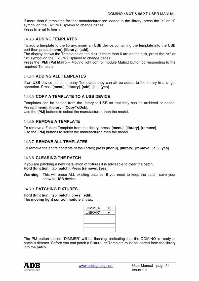
DOMINO 48 XT & 96 XT USER MANUAL
www.adblighting.com User Manual - page 54
Issue 1.1
If more than 6 templates for that manufacturer are loaded in the library, press the “>” or “<” symbol on the Fixture Displayer to change pages. Press [menu] to finish. 14.3.3 ADDING TEMPLATES To add a template to the library, insert an USB device containing the template into the USB port then press; [menu], [library], [add]. The display shows the Templates on the disk. If more than 6 are on the disk, press the “>” or “<” symbol on the Fixture Displayer to change pages. Press the [PM] (Pat Matrix – Moving light control module Matrix) button corresponding to the required Template. 14.3.4 ADDING ALL TEMPLATES If an USB device contains many Templates they can all be added to the library in a single operation. Press; [menu], [library], [add], [all], [yes]. 14.3.5 COPY A TEMPLATE TO A USB DEVICE Templates can be copied from the library to USB so that they can be archived or edited. Press; [menu], [library], [CopyToDsk]. Use the [PM] buttons to select the manufacturer, then the model. 14.3.6 REMOVE A TEMPLATE To remove a Fixture Template from the library; press; [menu], [library], [remove]. Use the [PM] buttons to select the manufacturer, then the model. 14.3.7 REMOVE ALL TEMPLATES To remove the entire contents of the library; press [menu], [library], [remove], [all], [yes]. 14.3.8 CLEARING THE PATCH If you are patching a new installation of fixtures it is advisable to clear the patch. Hold [function], tap [patch]. Press [remove], [yes].
Warning: This will erase ALL existing patches. If you need to keep the patch, save your show to USB device.
14.3.9 PATCHING FIXTURES Hold [function], tap [patch], press; [edit]. The moving light control module shows;
DIMMER ☼ LIBRARY ●
The PM button beside “DIMMER” will be flashing, indicating that the DOMINO is ready to patch a dimmer. Before you can patch a Fixture, its Template must be loaded from the library into the patch.
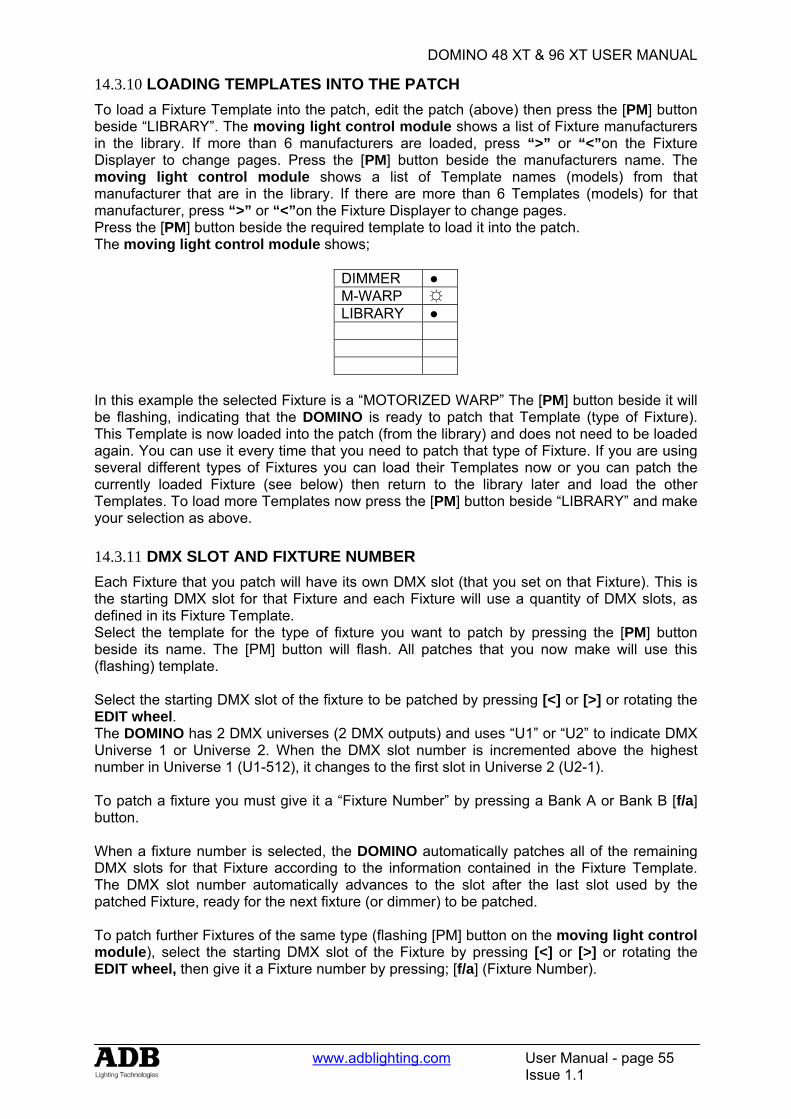
DOMINO 48 XT & 96 XT USER MANUAL
www.adblighting.com User Manual - page 55
Issue 1.1
14.3.10 LOADING TEMPLATES INTO THE PATCH To load a Fixture Template into the patch, edit the patch (above) then press the [PM] button beside “LIBRARY”. The moving light control module shows a list of Fixture manufacturers in the library. If more than 6 manufacturers are loaded, press “>” or “<”on the Fixture Displayer to change pages. Press the [PM] button beside the manufacturers name. The moving light control module shows a list of Template names (models) from that manufacturer that are in the library. If there are more than 6 Templates (models) for that manufacturer, press “>” or “<”on the Fixture Displayer to change pages. Press the [PM] button beside the required template to load it into the patch. The moving light control module shows;
DIMMER ● M-WARP ☼ LIBRARY ●
In this example the selected Fixture is a “MOTORIZED WARP” The [PM] button beside it will be flashing, indicating that the DOMINO is ready to patch that Template (type of Fixture). This Template is now loaded into the patch (from the library) and does not need to be loaded again. You can use it every time that you need to patch that type of Fixture. If you are using several different types of Fixtures you can load their Templates now or you can patch the currently loaded Fixture (see below) then return to the library later and load the other Templates. To load more Templates now press the [PM] button beside “LIBRARY” and make your selection as above. 14.3.11 DMX SLOT AND FIXTURE NUMBER Each Fixture that you patch will have its own DMX slot (that you set on that Fixture). This is the starting DMX slot for that Fixture and each Fixture will use a quantity of DMX slots, as defined in its Fixture Template. Select the template for the type of fixture you want to patch by pressing the [PM] button beside its name. The [PM] button will flash. All patches that you now make will use this (flashing) template. Select the starting DMX slot of the fixture to be patched by pressing [<] or [>] or rotating the EDIT wheel. The DOMINO has 2 DMX universes (2 DMX outputs) and uses “U1” or “U2” to indicate DMX Universe 1 or Universe 2. When the DMX slot number is incremented above the highest number in Universe 1 (U1-512), it changes to the first slot in Universe 2 (U2-1). To patch a fixture you must give it a “Fixture Number” by pressing a Bank A or Bank B [f/a] button. When a fixture number is selected, the DOMINO automatically patches all of the remaining DMX slots for that Fixture according to the information contained in the Fixture Template. The DMX slot number automatically advances to the slot after the last slot used by the patched Fixture, ready for the next fixture (or dimmer) to be patched. To patch further Fixtures of the same type (flashing [PM] button on the moving light control module), select the starting DMX slot of the Fixture by pressing [<] or [>] or rotating the EDIT wheel, then give it a Fixture number by pressing; [f/a] (Fixture Number).
DOMINO 48 XT & 96 XT USER MANUAL
www.adblighting.com User Manual - page 56
Issue 1.1
To patch a different type of Fixture, select its template by pressing the [PM] button beside its template name (it flashes) then select the starting DMX slot of the Fixture by pressing [<] or [>] or rotating the edit wheel , then give it a Fixture number by pressing; [f/a] (Fixture Number). Each patch that is made will use the Template indicated by the flashing [PM] button. If the Template you require is not shown, load it from the library as above. When finished patching press; [edit]. The patch is automatically saved. 14.3.12 PATCHING MULTIPLE FIXTURES Whilst patching (above), you can automatically patch a sequential range of Fixtures of the same type with contiguous DMX slots, to a sequential range of Fixture Numbers. Select the DMX slot of the first Fixture by pressing [<] or [>] or rotating the edit wheel . Select the Fixture Template on the moving light control module. HOLD the [f/a] button of the first Fixture Number then tap the [f/a] button of the last Fixture Number in the sequence. All Fixtures in the selected range are automatically patched. For example, to patch 10 Fixtures of the same type to Fixture Numbers 6 to 16 respectively and with the starting DMX slot of the first Fixture set to 100, press [<] or [>] or rotate the edit wheel to select DMX slot 100. HOLD [f/a] (6) and tap [f/a] (16)). All patches for all 10 Fixtures are automatically made. If finished patching press; [edit]. The patch is automatically saved. 14.3.13 PATCHING SCROLLERS OR FIXTURES WITH EXTERNAL DIMMERS Colour scrollers and some brands of fixture require a separate dimmer to control their intensity. The dimmer usually has a DMX slot number that is not related to the DMX slot numbers used by the scroller or fixture. Whilst patching (above), select the DMX slot of Fixture by pressing [<] or [>] or rotating the EDIT wheel. Select the Fixture Template on the moving light control module. Patch the fixture to a fixture number by pressing [f/a] (fixture number). The DOMINO display scrolls the message, “Fixture needs HTP channel”. The DOMINO knows that this scroller or fixture needs an external dimmer because it is defined in its template. Press; [OK]. Use the EDIT wheel or [<] or [>] to select the DMX slot of the external dimmer then press; [OK]. The fader of the ”fixture number“ button that was selected for the fixture number now controls the intensity of the dimmer and the moving light control module controls the scroller colours or fixture parameters. If finished patching press; [edit]. The patch is automatically saved. 14.3.14 INTENSITY PATCH LEVEL All fixture intensity attributes and dimmers can have a proportional (adjustable) patch level. When patching (above), select the DMX slot of the intensity channel (use EDIT wheel , [<] or [>]). The fixtures (or dimmers) [f/a] button will flash showing the existence of the patch. Hold down the FLASHING [f/a] button and the display shows the patch level. Whilst holding down the [f/a] button, rotate the edit wheel to set the patch level. The level of the patch is shown on the display. If you inadvertently select the DMX slot of a fixtures LTP attribute (instead of the HTP intensity attribute) the DOMINO will automatically adjust the patch level of the HTP intensity attribute associated with that fixture. 14.3.15 PATCH INDICATORS Whilst you are patching, the LEDs of any Fixture Number buttons that are patched are lit to show that they have been used. As each DMX slot is selected (with [<] or [>] or the EDIT wheel), if the displayed DMX slot is used (patched), its Fixture Number LED will flash.
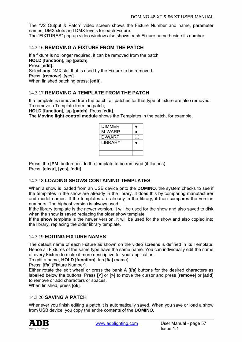
DOMINO 48 XT & 96 XT USER MANUAL
www.adblighting.com User Manual - page 57
Issue 1.1
The “V2 Output & Patch” video screen shows the Fixture Number and name, parameter names, DMX slots and DMX levels for each Fixture. The “FIXTURES” pop up video window also shows each Fixture name beside its number. 14.3.16 REMOVING A FIXTURE FROM THE PATCH If a fixture is no longer required, it can be removed from the patch HOLD [function], tap [patch]. Press [edit]. Select any DMX slot that is used by the Fixture to be removed. Press; [remove], [yes]. When finished patching press; [edit]. 14.3.17 REMOVING A TEMPLATE FROM THE PATCH If a template is removed from the patch, all patches for that type of fixture are also removed. To remove a Template from the patch; HOLD [function], tap [patch]. Press [edit]. The Moving light control module shows the Templates in the patch, for example,
DIMMER ● M-WARP ● D-WARP ☼ LIBRARY ●
Press; the [PM] button beside the template to be removed (it flashes). Press; [clear], [yes], [edit]. 14.3.18 LOADING SHOWS CONTAINING TEMPLATES When a show is loaded from an USB device onto the DOMINO, the system checks to see if the templates in the show are already in the library. It does this by comparing manufacturer and model names. If the templates are already in the library, it then compares the version numbers. The highest version is always used. If the library template is the newer version, it will be used for the show and also saved to disk when the show is saved replacing the older show template If the show template is the newer version, it will be used for the show and also copied into the library, replacing the older library template. 14.3.19 EDITING FIXTURE NAMES The default name of each Fixture as shown on the video screens is defined in its Template. Hence all Fixtures of the same type have the same name. You can individually edit the name of every Fixture to make it more descriptive for your application. To edit a name, HOLD [function], tap [f/a] (name). Press; [f/a] (Fixture Number). Either rotate the edit wheel or press the bank A [f/a] buttons for the desired characters as labelled below the buttons. Press [<] or [>] to move the cursor and press [remove] or [add] to remove or add characters or spaces. When finished, press [ok]. 14.3.20 SAVING A PATCH Whenever you finish editing a patch it is automatically saved. When you save or load a show from USB device, you copy the entire contents of the DOMINO.

DOMINO 48 XT & 96 XT USER MANUAL
www.adblighting.com User Manual - page 58
Issue 1.1
This includes the Patch. See the “UTILITIES” section for details. 14.3.21 INVERT PAN OR TILT You can invert the operation of the moving light control module pan and tilt displayers. This makes operation easier when a fixture is rigged such that mousing a displayer from left to right, pans the fixture from right to left or if it tilts in the wrong direction. To invert the operation of a fixtures pan or tilt parameters the fixture must be loaded on the moving light control module. Press [get], [f/a] (fixture number). Press [menu] [PM] (INVERT) The moving light control module shows the selected fixture number and the current state of its pan and tilt as either “normal” (green PM button) or “inverted” (red PM button).
PAN normal
TILT
inverted Fx #
To reverse a parameter press its flashing [PM] button. Tapping either end of the [fixture displayer] steps through the fixtures loaded on the moving light control module. When finished press [menu]. Video screens 1 and 2 indicate inverted pan or tilt parameters as follows; PAN –i TILT-i
DOMINO 48 XT & 96 XT USER MANUAL
www.adblighting.com User Manual - page 59
Issue 1.1
15. CONCEPTS FIXTURE PROGRAMMING
15.1 OVERVIEW There are two basic situations in which Fixtures (moving lights) are used in a show:
• A rehearsed show where every memory is pre programmed and executed on “GO” in the theatrical cross fade.
• A live and unrehearsed show where the lighting looks are created “on the fly”. The DOMINO provides all the tools to control fixtures in both situations.
15.2 THEATRICAL REHEARSED. In a Theatrical rehearsed and pre programmed show, each theatrical memory provides a total lighting look that has been recorded into the DOMINO using the [record memory] button. The show has usually had many rehearsals in which the theatrical memories, the submaster memories and the chasers have been refined (edited).
15.3 ON THE FLY Many “one off” or live shows do not have rehearsals. The lighting looks are created “on the fly” using “building block” memories that you record into the DOMINO prior to the show using the [store] or [store + level] buttons on the moving light control module. During the show, you combine different combinations of these “building block” memories to create each total lighting “look”. The difference between these “building block” (store button) and the “complete” (record memory button) memories of a fully programmed show are that “building block” contain Filtered information (only specific parameters) for the Fixture(s) in that memory. Some memories would only contain focus parameters. For example, one memory might only position the beams in a fan pattern, another positions them on some theatrical and submaster memories and yet another might set the beams in a cross pattern. These memories might also include intensity information but they will not contain any settings for any other parameters. Other memories might only contain Fixture colour parameters, that is, one memory might set its Fixtures to yellow, and another memory sets them to blue or another to red. Other memories might only select different gobos on the Fixtures to say “stars” or “dots”. Playback of a memory (created with building blocks) containing the fan pattern will not change the gobo or the colour because the fan memory has been Filtered to only contain pan and tilt parameters. Fading up the red memory changes the Fixtures to red but does not change any other parameters because colour was the only Filtered parameter when the memory was stored. Filters are a powerful tool that you will often use on the moving light control module. Thus by playing back various “filtered and stored” memories, you can create different combinations of focus (position), colour and beam (gobo). If, for example, you create 10 different focus (positional) memories, 8 different colour memories and 6 beam (gobo) memories then you can instantly create 480 (10x8x6) different looks on stage by using different combinations of these 24 “building block” memories.
DOMINO 48 XT & 96 XT USER MANUAL
www.adblighting.com User Manual - page 60
Issue 1.1
15.4 OUTPUT PHILOSOPHY The output philosophy is different for standard channels (generic luminaries) and fixture instruments. The used for generic (intensity only) channels is on a highest-takes-precedence (HTP) basis, and will be familiar to all operators. In this mode, the submaster or memory containing the highest intensity level will be the one contributing to the desk Output. Whilst this mode is sensible for intensity values, problems arise when it is used for fixture instrument. For that reason the method of controlling parameters is called latest-takes-precedence (LTP) mode, and provides a powerful means of control. The operator can use submasters, theatrical memories, submaster memories, chaser, cue lists in any order required, and the desk Output is taken from the last used. 15.4.1 LTP and Theatrical memories / Submaster memories So in the example above, to change the colour of some Fixtures grab the fader of the “red” building block memory and simply raise it (from zero). The submaster memory is triggered and the Fixtures change to red. The fader can be returned to zero or it can be left in the up position to show you which submaster memory you last triggered. Video 1 (channel view) also shows you the latest source for every parameter. To change to blue raise the “blue” memory fader from zero. To change to “star” gobos, raise the “star” memory fader from zero. To move the focus to the cross pattern, raise the cross pattern memory fader from zero. Each memory that you trigger only changes the (Filtered) parameters that you stored in that memory. You only have to fully fade up a memory if it contains intensity levels for the Fixtures because intensity is always under fader control. The [f/a] button below each submaster memory fader can also be pressed to momentarily trigger the parameters in a memory. For example, if the look on stage is currently blue, pressing the [f/a] button for the red memory will change the look to red. Releasing the [f/a] button will restore the blue look.
15.5 COMBINING THEATRICAL AND ON THE FLY If you intend to fully program a show, it is still useful to create your “building block” memories prior to the first rehearsal. You can then use them to quickly create looks on stage and then RECORD each look as a complete memory to be played back. When you are running a fully programmed show, you can still use your “building block” memories. To re-cap, the DOMINO with moving light control module provides two methods of programming.
• [record memory], (on the main DOMINO control panel) saves the entire output of the DOMINO into a memory. What you see is what you get.
• [store], (on the moving light control module) saves only selected (flashing) parameters of the Fixtures into a memory. You can select any parameters by using Filters. You can select any fixtures by using Hi-lights. Filters and Hi-lights are described in detail later in this manual. [store + level] also saves only selected parameters of the Fixtures but includes all intensity levels on the output PLUS all parameters of any fixtures not loaded on the moving light control module but with an intensity above zero on the output.

DOMINO 48 XT & 96 XT USER MANUAL
www.adblighting.com User Manual - page 61
Issue 1.1
15.6 FIXTURE INTENSITY CONTROL 15.6.1 INDIVIDIDUAL FIXTURES Each fixture that has been patched has its own intensity fader. The fixtures patched to the faders on the bank A always have their intensity fader available. The fixtures patched to the faders on the bank B only have their intensity fader available when the DOMINO is in “wide” mode. 15.6.2 MEMORY PLAYBACK
• If the theatrical memory was saved with the [record memory] buttons, the theatrical memory will contain the intensity levels.
• If the submaster memory was saved with the [record memory] or [store + level] buttons, the memory will contain the intensity levels. The intensity will be under control of its playback.
• If the submaster memory was saved with the [store] button, it will not contain any intensity levels. You can either use the individual fixture faders to control fixture intensity or you can use “Fixture Intensity Memories” as described below.
15.6.3 FIXTURE INTENSITY MEMORIES Instead of using the individual faders to control the intensity of each fixture, it is often more convenient to control the intensity of groups of fixtures by using a single fader for each group. This is achieved by programming memories that only contain intensity levels of selected fixtures (and no other parameters). To store a memory containing only fixture intensities. Fade up only the fixtures to be in the memory then load them onto the moving light control module by pressing; [get], [f/a] Clear all Hi-lights; [clear], [fixture displayer]. With no fixtures Hi-lighted, none of their parameters will be included in the memory that you store. To store the memory with only its intensity levels, press [store + level], [bank], [f/a] (memory number).
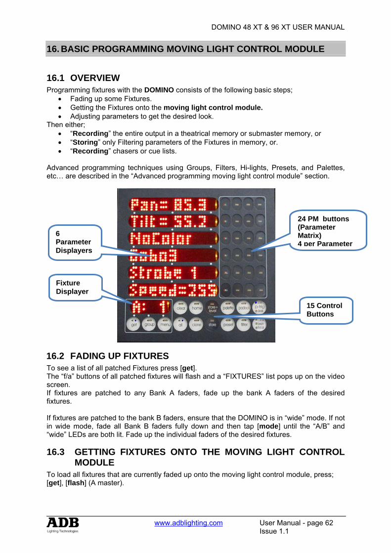
DOMINO 48 XT & 96 XT USER MANUAL
www.adblighting.com User Manual - page 62
Issue 1.1
16. BASIC PROGRAMMING MOVING LIGHT CONTROL MODULE
16.1 OVERVIEW Programming fixtures with the DOMINO consists of the following basic steps;
• Fading up some Fixtures. • Getting the Fixtures onto the moving light control module. • Adjusting parameters to get the desired look.
Then either; • “Recording” the entire output in a theatrical memory or submaster memory, or • “Storing” only Filtering parameters of the Fixtures in memory, or. • “Recording” chasers or cue lists.
Advanced programming techniques using Groups, Filters, Hi-lights, Presets, and Palettes, etc… are described in the “Advanced programming moving light control module” section.
16.2 FADING UP FIXTURES To see a list of all patched Fixtures press [get]. The “f/a” buttons of all patched fixtures will flash and a “FIXTURES” list pops up on the video screen. If fixtures are patched to any Bank A faders, fade up the bank A faders of the desired fixtures. If fixtures are patched to the bank B faders, ensure that the DOMINO is in “wide” mode. If not in wide mode, fade all Bank B faders fully down and then tap [mode] until the “A/B” and “wide” LEDs are both lit. Fade up the individual faders of the desired fixtures.
16.3 GETTING FIXTURES ONTO THE MOVING LIGHT CONTROL MODULE
To load all fixtures that are currently faded up onto the moving light control module, press; [get], [flash] (A master).
6 Parameter Displayers
24 PM buttons (Parameter Matrix) 4 per Parameter
Fixture Displayer
15 Control Buttons
DOMINO 48 XT & 96 XT USER MANUAL
www.adblighting.com User Manual - page 63
Issue 1.1
Note: This method of loading fixtures clears any existing fixtures from the Moving light control module. Fixtures can also be loaded individually, in ranges, from groups, presets, palettes or filter memories as described in the “Advanced Programming” section.
16.4 ALL MODE When multiple fixtures are loaded onto the moving light control module in the one operation, “ALL” mode is automatically selected. As soon as you touch a parameter displayer to alter is value, that same parameter on all other Hi-lighted Fixtures of the same type will immediately follow any changes on the selected Fixture. If you want to only control the currently selected fixture, turn off “ALL” mode by pressing [all] (toggle action).
16.5 SELECTING A FIXTURE To select any of the loaded fixtures, tap either end of the Fixture Displayer. Tap the left to select the next lower Fixture Number. Tap the right to select the next higher Fixture Number. To change directly to a specific Fixture Number, HOLD the centre of the Fixture Displayer, then tap [f/a] (Fixture Number). The Fixture Number of the currently selected Fixture is shown on the Fixture Displayer and also indicated on the video screen by a row of colons. The moving light control module can now control the parameters of this Fixture.
16.6 CONTROLLING THE SELECTED FIXTURE When a fixture is selected on the moving light control module its Fixture Number is shown on the Fixture Displayer and all of its available “PM” (Parameters Matrix) buttons are active. Each of the 6 parameter displayers can be used to control up to 4 parameters as selected by the 4 [PM] buttons beside it. This allows a minimum of 24 parameters to be controlled. The number of “PM” buttons that are available and the actual parameters that each of these PM buttons selects are defined each Fixture’s Template. The colour of the PM buttons indicates their status or function;
• Red + White + Blue. This parameter is active on the parameter displayer to its left. • Red. This is a colour parameter and it is not currently active. Pressing this PM button
will select it on the parameter displayer to its left. • Blue. This is a beam parameter and it is not currently active. Pressing this PM button
will select it on the parameter displayer to its left. • Green. This is a focus parameter and it is not currently active. Pressing this PM
button will select it on the parameter displayer to its left. • Red + Blue. This is a parameter that cannot be stored in a submaster memory (No
Store) and it is not currently active. Pressing this PM button will select it on the parameter displayer to its left.
When a parameter is selected (by pressing its PM button) its displayer will show the Name of the parameter and the PM button will light red + white + blue to show that it is active. There are three display levels of information available on the displayers for each parameter, Name, Value and Time. Tapping an active [PM] button will toggle its parameter displayer between Name and Value. Tapping a parameter displayer that is showing a Name will also change it to Value.

DOMINO 48 XT & 96 XT USER MANUAL
www.adblighting.com User Manual - page 64
Issue 1.1
• Name – Displays the name of the current parameter. e.g. “PAN“or “Colour”. • Value – Displays the current value of the parameter. e.g. “Pan= 35D” or “Green” and
allows you to alter the value by touching and scrolling the displayer. Pressing and HOLDING a [PM] button will change its displayer to:
• Time – Displays the timing information that will be recorded/stored for that parameter and allows you to alter the timing information (see the “Advanced Programming” section for details).
Tapping a [PM] button returns its displayer to Name. There are three yellow LEDs located at the right end of each parameter displayer and they indicate which level of information is being displayed.
• Top yellow LED = Name • Mid yellow LED = Value • Low yellow LED = Time.
To quickly restore all parameter displayers to the Names of the parameters that they control press; [clear], [clear].
16.7 ADJUSTING PARAMETER VALUES In Value and Time modes, each touch sensitive displayer can be used to adjust its parameter value by “mousing” the display. Use the edge of your finger to get the best response from the displayer. For fine adjustment “roll” the edge of your finger. When you have touched a displayer, the Mid (Name) or Low (Time) yellow LEDs will flash. Whilst they are flashing, the EDIT wheel can also be used to vary the value. Use the edit wheel for very fine adjustments. If the edit wheel is not moved for 30 seconds, the yellow LED will stop flashing and the edit wheel will revert to scrolling the V1 or V2 video page. To manually revert to scrolling the V1 or V2 video page press [ok]. To re-connect the edit wheel to a parameter displayer or connect it to a different displayer, touch the required displayer. To connect the edit wheel to the next parameter, press [>]. To connect the edit wheel to the previous parameter, press [<]. For example, whilst adjusting pan with the EDIT wheel, if you press [>], the wheel will now adjust tilt. If you press [>] again, the edit wheel will connect to the next parameter such as colour. Pressing [<] connects it back to tilt. The parameters that can be selected for the EDIT wheel with the < and > buttons can be restricted by the use of filters. For example, if no filters are selected, the < and > buttons can be used to step through all parameters of a fixture. If only pan and tilt have filters applied, then the < and > buttons are restricted to only selecting pan and tilt. See “Filters” below for details on how to apply filters. Different parameters can be adjusted in different ways. The way each parameter is adjusted is defined in its Fixture’s Template.
• The value of each parameter might be continuously variable (e.g. Pan). • It might jump between pre-defined values called wheel stops (e.g. Gobo 1, Gobo 2
etc). • There might be variable areas within wheel stops (e.g. gobo spin speed).
16.7.1 VARIABLE PARAMETERS When a parameter is continuously variable, the displayer will show the name of the parameter and an “equals” sign (=) followed by its value. E.g. Pan = 25D. (25 Degrees) You can use your finger or a stylus to “mouse” the displayer and hence alter the value of the parameter. If you touch anywhere on a displayer, its yellow LED flashes and the EDIT wheel can also be used to vary the value.
DOMINO 48 XT & 96 XT USER MANUAL
www.adblighting.com User Manual - page 65
Issue 1.1
16.7.2 TRACKBALL (MOUSE) FOR PAN AND TILT When a parameter is pan or tilt the displayer will show the name of the parameter and an “equals” sign (=) followed by its value. E.g. Pan = 25D. (25 Degrees) You can use a trackball or mouse to “mouse” the displayer and hence alter the value of the parameter. 16.7.3 WHEEL STOPS If wheel stops are available, the displayer will show the name of the current wheel stop, e.g. Gobo 1. Tapping on the left or right ends of the displayer will STEP the parameter through the wheel stops. E.g. Gobo 1, Gobo 2, Gobo 3, etc. You can also “mouse” the displayer to quickly step through the stops. When the yellow LED flashes, the EDIT wheel can also be used to step through the wheel stops. 16.7.4 VARIABLES WITHIN WHEEL STOPS If the current wheel stop allows a variable range to be controlled, the displayer will show the name of the wheel stop followed by a “colon” (:) then its value. E.g. Strobe: 52. You can use your finger to “mouse” within the central area of the displayer and hence alter the value of the parameter within the limits of that wheel stop. If you touch the central area on a displayer, its yellow LED flashes and the EDIT wheel can also be used to vary the value. Tapping either end of the displayer will step to the next wheel stop. 16.7.5 PARAMETER TIMES In Time mode (HOLD the [PM] button), there are 3 pages of settings available for every parameter. Tapping on the left or right ends of the displayer will step through the pages. When a page is displayed, you can alter its settings by mousing the central area of the displayer or if you touch the central area on a displayer, its yellow LED flashes and the EDIT wheel can also be used to vary the value. See the “Advanced Programming” section for details on times. 16.7.6 HOME You can send a Fixture to its “home” position (parameter values as defined in its Template). Typically the home position will be an open white beam with pan and tilt in their mid positions. This can be useful if you cannot see a Fixtures beam and you want to check or alter its parameters. To send a Fixture to its home position, select the Fixture on the Fixture Displayer then press; [home], [fixture displayer]. To send ALL Fixtures on the moving light control module. to their home positions, press; [home], [all]. 16.7.7 FILTERS You decide which parameters you want to “store” by selecting the appropriate Filters. When a Fixture is loaded onto the moving light control module it will not have any Filters so all of its parameters will be flashing on the moving light control module and the “V4 MOVING LIGHT VIEW” video screen. When one or more parameters are filtered, only the filtered parameters will flash.
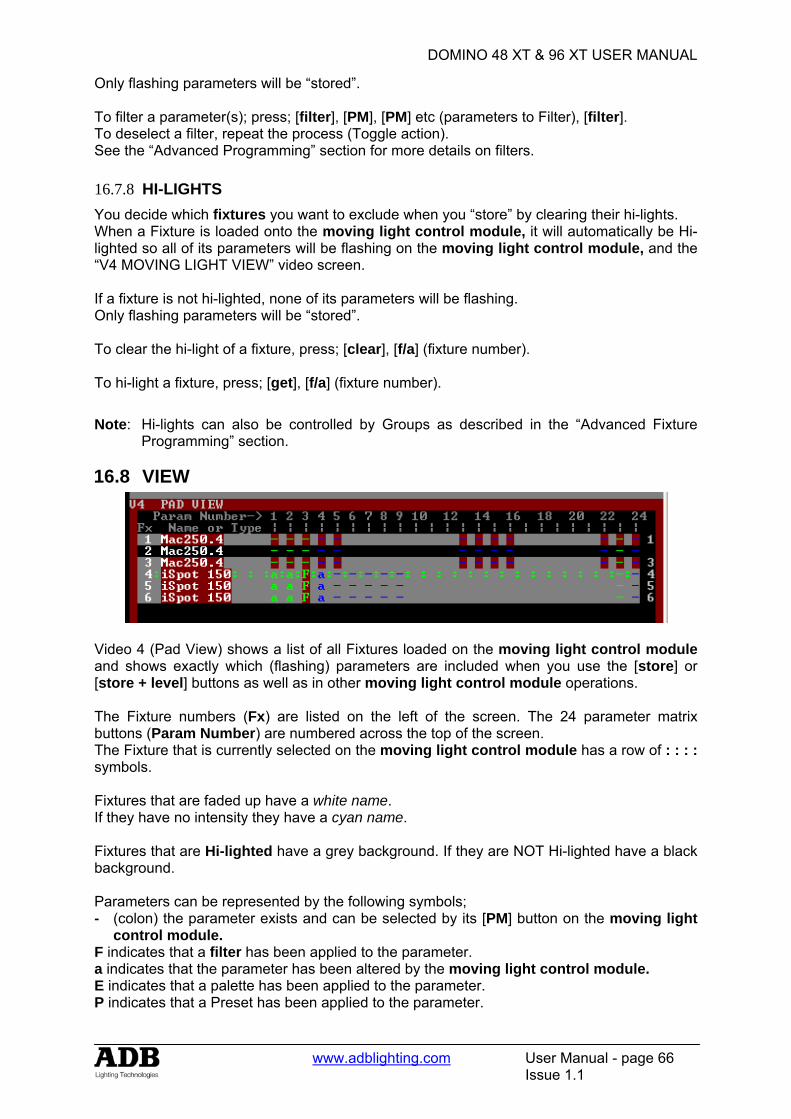
DOMINO 48 XT & 96 XT USER MANUAL
www.adblighting.com User Manual - page 66
Issue 1.1
Only flashing parameters will be “stored”. To filter a parameter(s); press; [filter], [PM], [PM] etc (parameters to Filter), [filter]. To deselect a filter, repeat the process (Toggle action). See the “Advanced Programming” section for more details on filters. 16.7.8 HI-LIGHTS You decide which fixtures you want to exclude when you “store” by clearing their hi-lights. When a Fixture is loaded onto the moving light control module, it will automatically be Hi-lighted so all of its parameters will be flashing on the moving light control module, and the “V4 MOVING LIGHT VIEW” video screen. If a fixture is not hi-lighted, none of its parameters will be flashing. Only flashing parameters will be “stored”. To clear the hi-light of a fixture, press; [clear], [f/a] (fixture number). To hi-light a fixture, press; [get], [f/a] (fixture number).
Note: Hi-lights can also be controlled by Groups as described in the “Advanced Fixture Programming” section.
16.8 VIEW
Video 4 (Pad View) shows a list of all Fixtures loaded on the moving light control module and shows exactly which (flashing) parameters are included when you use the [store] or [store + level] buttons as well as in other moving light control module operations. The Fixture numbers (Fx) are listed on the left of the screen. The 24 parameter matrix buttons (Param Number) are numbered across the top of the screen. The Fixture that is currently selected on the moving light control module has a row of : : : : symbols. Fixtures that are faded up have a white name. If they have no intensity they have a cyan name. Fixtures that are Hi-lighted have a grey background. If they are NOT Hi-lighted have a black background. Parameters can be represented by the following symbols; - (colon) the parameter exists and can be selected by its [PM] button on the moving light
control module. F indicates that a filter has been applied to the parameter. a indicates that the parameter has been altered by the moving light control module. E indicates that a palette has been applied to the parameter. P indicates that a Preset has been applied to the parameter.
DOMINO 48 XT & 96 XT USER MANUAL
www.adblighting.com User Manual - page 67
Issue 1.1
See the “Advanced Programming” section for details on Palettes and Presets.
Hint: The most important information conveyed by the PADVIEW screen (and also on the moving light control module) is that any Parameters that are included when you use the [store] or [store + level] buttons will be flashing.
16.9 SAVING THEATRICAL MEMORIES When you have adjusted the parameters of your fixtures you can save the settings (including parameter times) in theatrical memory. • RECORD THEATRICAL MEMORY. To record the entire output press; [record memory],
[wheel] (optional, select memory number). [<] or [>]( optional point memories) [Ok]
16.10 SAVING SUBMASTER MEMORIES When you have adjusted the parameters of your fixtures you can save the settings (including parameter times) in theatrical and submaster memories memory. The DOMINO provides several ways of programming theatrical and submaster memories into memory. • RECORD SUBMASTER MEMORY. To record the entire output press; [record memory],
[page] (optional Bank B or Bank C), [f/a] (Bank B or C submaster memory number);
16.11 BUILDING BLOCK MEMORIES • STORE. To store building block memories of only flashing parameters press; [store],
[page] (optional Bank B or Bank C), [f/a] (Bank B or C submaster memory number). • STORE + LEVEL. To store a submaster memories of only flashing parameters AND all
intensity levels on the output press; [store + level], [page], [f/a].
16.12 SAVING CHASERS To record a chaser, press; [record chaser]. Select a memory number for the chaser, press; [page], [f/a]. Each step of a chaser consists of an either a previously recorded theatrical or submaster memory. [store+level]. Continue to record steps as above. You may mix snapshots, parameters or theatrical and submaster memories in any order. When all steps have been recorded, complete the chaser by pressing; [record chaser].
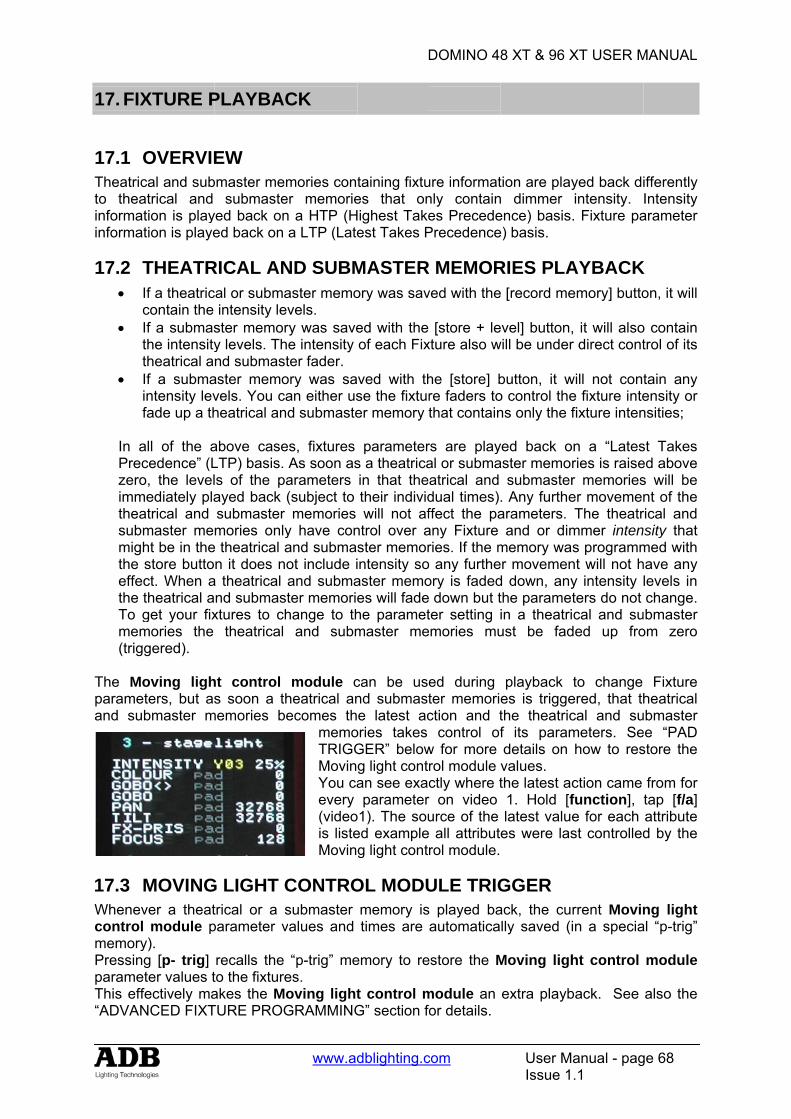
17. FIX
17.1 Theatricto theainformainforma
17.2 T•
c•
tt
•
f In aPreczeroimmtheasubmmighthe effethe To gmem(trig
The Moparameand su
17.3 WhenevcontrolmemoryPressinparameThis eff“ADVAN
XTURE P
OVERVIEcal and subatrical and tion is playtion is playe
THEATRIf a theatriccontain the If a submasthe intensitytheatrical aIf a submaintensity levfade up a th
all of the acedence” (Lo, the level
mediately plaatrical and master meht be in thestore buttoct. When atheatrical aget your fixmories the gered).
oving ligheters, but asbmaster m
MOVINGver a theat module p
y). g [p- trig]
eter values tfectively maNCED FIXT
PLAYBAC
EW bmaster me
submasteyed back oned back on
RICAL ANcal or subma
intensity lester memory levels. Thnd submast
aster memovels. You caheatrical an
above caseLTP) basis. ls of the paayed back submaster mories only
e theatrical an it does n
a theatrical nd submasxtures to ch
theatrical
ht control s soon a th
memories b
G LIGHT Ctrical or a sparameter v
recalls the to the fixtureakes the MoTURE PROG
www.ad
CK
mories conter memorien a HTP (Ha LTP (Late
ND SUBMaster memo
evels. ry was savehe intensity ter fader.
ory was saan either us
nd submaste
es, fixtures As soon asarameters (subject to memories
y have conand submasot include iand submater memoriehange to th
and subm
module cheatrical anecomes th
memoTRIGGMovinYou caevery (videois listeMovin
CONTROsubmaster values and
“p-trig” mees. oving lightGRAMMING
D
dblighting.c
taining fixtues that on
Highest Takeest Takes P
MASTERory was sav
ed with the of each Fix
ved with thse the fixturer memory t
parameters a theatricain that thetheir individwill not af
ntrol over aster memorintensity soaster memoes will fadehe parametmaster me
can be usend submaste latest ac
ories takes GER” belowg light contan see exacparameter
o1). The soued exampleg light cont
OL MODUmemory istimes are
emory to re
t control mG” section fo
DOMINO 4
com
ure informatnly containes PrecedePrecedence
R MEMORved with the
[store + lexture also w
he [store] bre faders tothat contain
rs are playal or submaatrical and dual times)ffect the paany Fixture ries. If the m
o any furtheory is faded down but tter setting
emories mu
ed during ter memoriction and t
control ofw for more rol module ctly where tr on video urce of the all attributrol module.
ULE TRIGs played baautomatica
estore the M
module an or details.
8 XT & 96 X
User MIssue 1
tion are playn dimmer ence) basise) basis.
RIES PLAe [record me
evel] button,will be under
button, it wo control thens only the f
yed back oaster memo
submaster. Any furthearameters.
and or dimmemory waer movemend down, anythe parametin a theatriust be fad
playback es is triggethe theatricf its paramdetails on values. the latest ac1. Hold [flatest valuees were las
GGER ack, the cully saved (i
Moving ligh
extra playb
XT USER M
anual - pag.1
yed back diintensity. . Fixture pa
AYBACKemory] butto
, it will alsor direct cont
will not conte fixture intefixture inten
on a “Latesries is raiser memorieser movemenThe theatr
mmer intens programm
nt will not hy intensity ters do not cal and su
ded up fro
to change ered, that thcal and sumeters. Sehow to res
ction came function], e for each st controlled
rrent Movinin a specia
ht control
back. See
MANUAL
ge 68
ifferently Intensity arameter
K on, it will
o contain trol of its
tain any ensity or nsities;
st Takes ed above s will be nt of the rical and nsity that med with have any levels in change.
ubmaster om zero
Fixture heatrical
ubmaster ee “PAD store the
from for tap [f/a] attribute d by the
ng light al “p-trig”
module
also the
DOMINO 48 XT & 96 XT USER MANUAL
www.adblighting.com User Manual - page 69
Issue 1.1
17.4 MEMORIES FLASH To momentarily and instantly playback a theatrical and submaster memories, press; [f/a] (theatrical and submaster memories fader). When you release the flash button the fixtures instantly return to their previous settings.
17.5 MOVING LIGHT CONTROL MODULE LOCK You can prevent a parameter from moving when a memories is played back (triggered) by using the padlock function. If [padlock] is pressed (its LED lights blue), the flashing parameters of any Fixture on the Moving light control module will not respond to any playback from theatrical and submaster memories or chasers. You determine which parameters are flashing by using Filters and/or Hi-lights.
17.6 PALETTE PLAYBACK (E-MOD) If HOLD [palette], it will lock on. “E-Mod” is shown on the domino display. You can now use the Bank A [f/a] buttons for live playback your palettes. This effectively doubles the number of available playbacks. Press [palette] again to de-select E-Mod mode. See “ADVANCED FIXTURE PROGRAMMING” for more details on Palettes.
17.7 PRESET PLAYBACK (P-MOD) If HOLD [preset], it will lock on. “P-Mod” is shown on the domino display. You can now use the Bank A [f/a] buttons for live playback your presets. This effectively doubles the number of available playbacks. Press [preset] again to de-select P-Mod mode. See “ADVANCED FIXTURE PROGRAMMING” for more details on Presets.
17.8 CHASER PLAYBACK Chasers are recorded and played back in the normal way as described in the “CHASERS” section. As with theatrical and submaster memories, if the chaser steps were created using the [store] button, the chaser will not contain any intensity information. To control the intensity use both the fixture faders and or fade up a theatrical or submaster memories that contains only the fixture intensities.
17.9 COMBINING AND VARYING CHASERS When you playback a chaser that consists of steps only containing “filtered” parameters it is easy to vary the look of the chaser whilst it is being played. For example; Record a three step chaser with different focus (pan and tilt) positions for each step using filters to store only focus parameters. Record three submaster memories with a different colour (red, blue, yellow) in each submaster memory using filters to store only colour parameters. Playback the chaser. The fixtures move. Raise the fader of the red submaster memories and the chaser turns red. Raise the fader of the yellow theatrical and submaster memories and the chaser turns yellow. Raise the fader of the blue submaster memories and the chaser turns blue. The chaser changes to the latest colour (LTP) to be faded up from zero. Press the [f/a] buttons of the red, blue or yellow submaster memories and the chaser momentarily changes to the selected colour.

DOMINO 48 XT & 96 XT USER MANUAL
www.adblighting.com User Manual - page 70
Issue 1.1
The same techniques can be used to change other parameters in the chaser such as gobo or shutter by storing submaster memories that are Filtered to only contain those parameters. You can also use P-MOD or E-MOD (above) to vary the chaser. 17.9.1 CHASER TIMES The chaser rate can be varied, which changes the time between steps. The times taken for Fixture parameters to move when their step is triggered, is dependent upon the “As Chaser” flags for each parameter. The default setting for these flags depends upon the type of parameter.
• Colour and beam parameters have their “As Chaser” flag set to “No” by default. They therefore use the times that are in the theatrical and submaster memories that make up the steps. They ignore the chaser crossfade setting.
• Focus parameter have their “As Chaser” flag set to “Yes” by default. Their times are therefore under the control of the chaser crossfade setting. This allows the speed of Fixture movement (focus) to be easily controlled without the need to edit the times in every step. If the chaser is snapping from step to step, the focus parameters also snap. If the chaser has a crossfade setting, the focus parameters will slowly move from step to step as determined by the chaser rate and percentage crossfade.
By default, only the focus parameters are affected by the chaser crossfade. Therefore, parameters such as gobo or colour wheels will not make slow movements from step to step. Typically they will be set to zero time so that they snap change. If your fixtures have colour mixing features, simply set the colour parameter “As-Chaser” flag to “yes” and the colour mixing will be under control of the chaser crossfade.
DOMINO 48 XT & 96 XT USER MANUAL
www.adblighting.com User Manual - page 71
Issue 1.1
18. ADVANCED FIXTURE PROGRAMMING
Some of the following functions have already been mentioned earlier in this manual. This section gives additional descriptions of these functions plus many additional methods of operation.
18.1 LOADING FIXTURES There are several ways to get fixtures onto the moving light control module. To get a Fixture press; [get], [f/a] (Fixture Number). To get several Fixtures, HOLD [get], then tap; [f/a] (Fixture Number), [f/a] (Fixture Number), etc. Release [get]. To get a range of fixtures, press and release [get]. HOLD [f/a] (first fixture in range), then tap [f/a] (last fixture in range). Both selected fixtures and all fixtures in between them are loaded. To get all patched fixtures press; [get], [all]. To get all fixtures in a memory including all filter selections and values in the memory, press; [get], [store], [page] (optional red or blue page), [f/a] (memory number). All of the above operations add the selected fixtures to the fixtures already on the Moving light control module. To get only fixtures that have an intensity above zero (and clear all other fixtures from the Moving light control module), fade up the required Fixtures then press; [get], [flash] (bank A master).
18.2 ALL MODE When multiple fixtures are loaded on the Moving light control module in a single operation, ALL mode is automatically selected. The letter “A” appears on the fixture displayer beside the selected fixture number and the “all” button lights. The video screen V4 “Pad View” reads; “The ALL MODE is active on the Pad.” To manually select “ALL MODE“, press [all]. When “All Mode” is active, all Fixtures that are both Hi-lighted AND of the same type as the selected Fixture can be controlled simultaneously. As soon as you touch a displayer, that same parameter on all other Hi-lighted Fixtures of the same type will immediately follow. To control only the currently selected fixture, turn off ALL mode by pressing [all] (toggle action).
Hint: Use all mode to quickly select the same colour or gobo etc on all Fixtures of the same type. Use Hi-lights to select which fixtures are affected by ALL modes.
18.3 CLEARING FIXTURES To clear all fixtures from the Moving light control module press; [clear], [all].
18.4 HOME A Fixtures “home” position is a set of parameter values defined in its Template. Typically the home position will be an open white beam with pan and tilt in their mid positions.
DOMINO 48 XT & 96 XT USER MANUAL
www.adblighting.com User Manual - page 72
Issue 1.1
Homing a fixture also resets all of its parameter times on the Moving light control module to the default values. To send a Fixture to its home position, select the Fixture on the Fixture Displayer then press; [home], [fixture displayer]. To momentarily send a Fixture to its home position, press; [home], [f/a] (Fixture Number). When the [f/a] button is released, the Fixture returns to its previous settings. Multiple [f/a] buttons can be pressed at the same time. When finished, press [home] again to de-select it. To send filtered (flashing) parameters to their home positions, press; [home], [filter]. To send ALL Fixtures on the Moving light control module to their home positions, press; [home], [all]. To send ALL patched Fixtures to their home positions, clear the Moving light control module [clear], [all], then press; [home], [all]. To send ALL Fixtures that have some intensity level on the output to their home positions, press; [home], [flash] (bank A master).
18.5 P-TRIG The Moving light control module has its own special memory known as the “p-trig” memory. The current Moving light control module settings are automatically stored in “p-trig” memory whenever either; Fixtures are loaded onto the Moving light control module .or A memory is played back. If parameter values are altered via the Moving light control module or the playback of a memory, then pressing [p-trig] recalls the “p-trig” memory to restore the previous Moving light control module parameter values.
Hint; If you inadvertently adjust the wrong fixture on the Moving light control module, you can quickly restore all loaded fixtures to their previous state by pressing; [p-trig].
See also “Previewing Times with P-trig” below.
18.6 PARAMETER TIMES In Time mode (HOLD the parameters PM button), there are 3 pages of settings available for every parameter. Tapping on the left or right ends of the displayer will step through the three pages. When a page is displayed, you can alter its settings by mousing the central area of the displayer or if you touch the central area on a displayer, its yellow LED flashes and the EDIT wheel can also be used to vary the value. The 3 time pages are; 1. Mov = 2.0s. This is the time taken for the parameter to “move” to the value that you store or record in a memory or chaser step. When you playback (trigger) the memory or chaser step, this parameter will take this time to move to its value in the memory or step. This is subject to the flag settings described below. The move time is adjustable from 0 seconds to more than 16 minutes. The default time is 2 seconds for pan and tilt and 0 seconds for all other parameters. You can either “mouse” the displayer, or if you touch the central area of the displayer, its yellow LED flashes and the EDIT wheel can also be used to vary the value. See “LTP” in the “Terminology” section for more details on when this time is triggered.
DOMINO 48 XT & 96 XT USER MANUAL
www.adblighting.com User Manual - page 73
Issue 1.1
2. Dly = 0.0s. This is the “delay” time that must expire after a memory or step is triggered before the Move time (above) starts. This is subject to the flag settings described below. The delay time is adjustable from 0 seconds to more than 16 minutes with a default time of 0 seconds. You can either “mouse” the displayer, or if you touch the central area of the displayer, its yellow LED flashes and the EDIT wheel can also be used to vary the value. 3. Flags:- - - When Flags:--- is displayed, tapping the centre of the displayer selects the FLAGS menu. When the FLAGS menu is selected, tapping either end of the displayer steps through the available flags. Tapping the centre of a displayer selects that flag. The following flags are available; As-Pan. Tapping the centre of the displayer toggles between N (No) or Y (Yes). When set to N, the parameter will use its own Move and Delay settings. When set to Y, the parameter will move when and in the same move time as set for the PAN parameter of the fixture. This flag is not available for the Pan parameter. PanEnd. Tapping the centre of the displayer toggles between N (No) or Y (Yes). When set to Y, the parameter will snap move (zero time) at the end of the Pan movement. This flag is not available for the Pan parameter. As-Tilt. Tapping the centre of the displayer toggles between N (No) or Y (Yes). When set to N, the parameter will use its own Move and Delay settings. When set to Y, the parameter will move when and in the same move time as set for the TILT parameter of the fixture. This flag is not available for the Pan parameter. Tilt-End. Tapping the centre of the displayer toggles between N (No) or Y (Yes). When set to Y, the parameter will snap move (zero time) at the end of the Tilt movement. This flag is not available for the Pan parameter. As-Chaser. Tapping the centre of the displayer toggles between N (No) or Y (Yes). When set to Y, this parameter, when played back as part of a CHASER, will use the crossfade setting of the chaser. The default setting for the “As-Chaser” flag for Pan and Tilt parameters is Y. This means that when you record a chaser and then play it back, you can use the chaser rate and crossfade controls to easily adjust the pan and tilt move times. If you want to create a complex chaser where every step uses the individual parameter times, set the “As-Chaser” flag to N and set each individual parameter time for every step. The default setting for the “As-Chaser” flag for all other parameters is N. This means that parameters such as gobos and colours will not be influenced by the crossfade settings of the chaser and use the individual parameter times. Typically you would set gobo and colour wheel parameter times to zero so that they snap change on each step and use slow times for colour mixing parameters so that colours blend from step to step. The Flags page shows exactly which flags (if any) have been set to yes
Flags: - - - No Flags Flags: - P - As Pan Flags: EP - End Pan Flags: - T - As Tilt Flags: - - C As Chaser
Hint: See “Previewing Times” later in this section for more information.
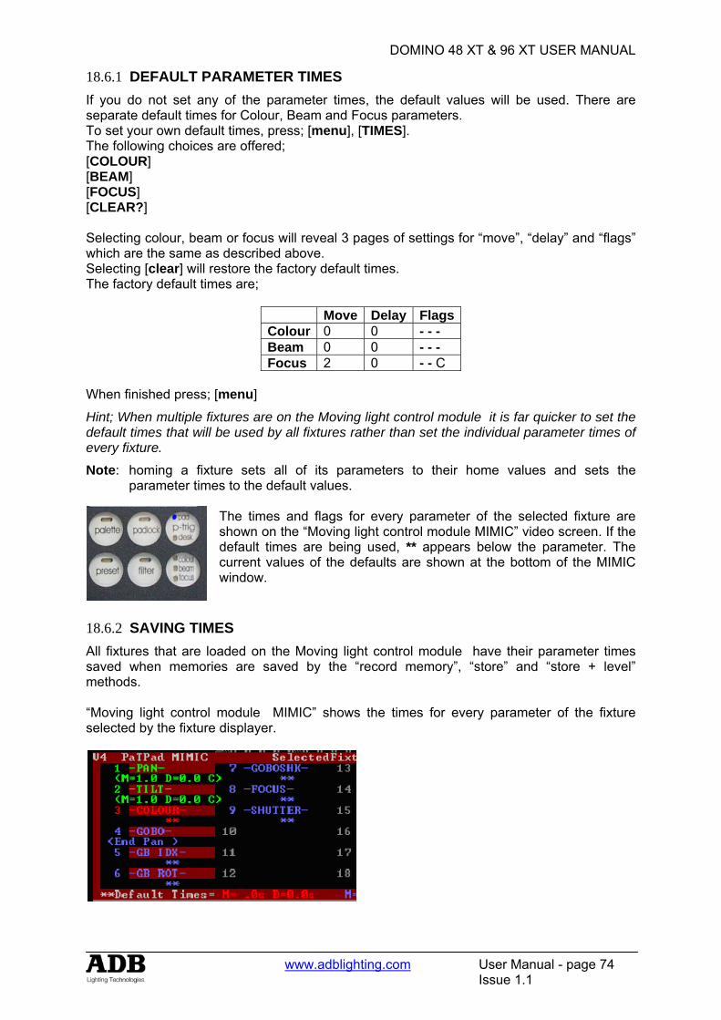
DOMINO 48 XT & 96 XT USER MANUAL
www.adblighting.com User Manual - page 74
Issue 1.1
18.6.1 DEFAULT PARAMETER TIMES If you do not set any of the parameter times, the default values will be used. There are separate default times for Colour, Beam and Focus parameters. To set your own default times, press; [menu], [TIMES]. The following choices are offered; [COLOUR] [BEAM] [FOCUS] [CLEAR?] Selecting colour, beam or focus will reveal 3 pages of settings for “move”, “delay” and “flags” which are the same as described above. Selecting [clear] will restore the factory default times. The factory default times are;
Move Delay FlagsColour 0 0 - - - Beam 0 0 - - - Focus 2 0 - - C
When finished press; [menu]
Hint; When multiple fixtures are on the Moving light control module it is far quicker to set the default times that will be used by all fixtures rather than set the individual parameter times of every fixture.
Note: homing a fixture sets all of its parameters to their home values and sets the parameter times to the default values.
The times and flags for every parameter of the selected fixture are shown on the “Moving light control module MIMIC” video screen. If the default times are being used, ** appears below the parameter. The current values of the defaults are shown at the bottom of the MIMIC window.
18.6.2 SAVING TIMES All fixtures that are loaded on the Moving light control module have their parameter times saved when memories are saved by the “record memory”, “store” and “store + level” methods. “Moving light control module MIMIC” shows the times for every parameter of the fixture selected by the fixture displayer.
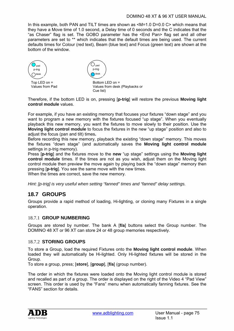
DOMINO 48 XT & 96 XT USER MANUAL
www.adblighting.com User Manual - page 75
Issue 1.1
In this example, both PAN and TILT times are shown as <M=1.0 D=0.0 C> which means that they have a Move time of 1.0 second, a Delay time of 0 seconds and the C indicates that the “as Chaser” flag is set. The GOBO parameter has the <End Pan> flag set and all other parameters are set to ** which indicates that the default times are being used. The current defaults times for Colour (red text), Beam (blue text) and Focus (green text) are shown at the bottom of the window.
Therefore, if the bottom LED is on, pressing [p-trig] will restore the previous Moving light control module values. For example, if you have an existing memory that focuses your fixtures “down stage” and you want to program a new memory with the fixtures focused “up stage”. When you eventually playback this new memory, you want the fixtures to move slowly to their position. Use the Moving light control module to focus the fixtures in the new “up stage” position and also to adjust the focus (pan and tilt) times. Before recording this new memory, playback the existing “down stage” memory. This moves the fixtures “down stage” (and automatically saves the Moving light control module settings in p-trig memory). Press [p-trig] and the fixtures move to the new “up stage” settings using the Moving light control module times. If the times are not as you wish, adjust them on the Moving light control module then preview the move again by playing back the “down stage” memory then pressing [p-trig]. You see the same move with the new times. When the times are correct, save the new memory. Hint: [p-trig] is very useful when setting “fanned” times and “fanned” delay settings.
18.7 GROUPS Groups provide a rapid method of loading, Hi-lighting, or cloning many Fixtures in a single operation. 18.7.1 GROUP NUMBERING Groups are stored by number. The bank A [f/a] buttons select the Group number. The DOMINO 48 XT or 96 XT can store 24 or 48 group memories respectively. 18.7.2 STORING GROUPS To store a Group, load the required Fixtures onto the Moving light control module. When loaded they will automatically be Hi-lighted. Only Hi-lighted fixtures will be stored in the Group. To store a group, press; [store], [group], [f/a] (group number). The order in which the fixtures were loaded onto the Moving light control module is stored and recalled as part of a group. The order is displayed on the right of the Video 4 “Pad View” screen. This order is used by the “Fans” menu when automatically fanning fixtures. See the “FANS” section for details.
Top LED on = Values from Pad
Bottom LED on = Values from desk (Playbacks or Cue list)
p-trig pad
desk
p-trig pad
desk
DOMINO 48 XT & 96 XT USER MANUAL
www.adblighting.com User Manual - page 76
Issue 1.1
18.7.3 LOADING GROUPS To load a group of fixtures onto the Moving light control module press; [get], [group]. The [group] buttons lights orange and the [f/a] buttons of all bank A faders that have a group stored in them will flash. The “GROUP MEMORY” video window pops up displaying a list of all groups. To load press; [f/a] (group number). To load several groups, press; [get], HOLD [group], then tap; [f/a] (group number) [f/a] (group number) [f/a] (group number), etc. To load a range of groups, press; [get], [group]. HOLD [f/a] (first group in range), then tap [f/a] (last group in range). Both selected groups and all groups in between them are loaded. 18.7.4 Changing Hi-Lights Using Groups Hi-lights are used to either include (Hi-light) or exclude (NO Hi-light) already loaded Fixtures from certain operations on the moving light control module. See “FILTERS and HI-LIGHTS” for more details To ONLY Hi-light the fixtures in a group (and clear the Hi-lights of all other fixtures), press; [group], [f/a] (group number). To ONLY Hi-light the fixtures in a range of groups (and clear the Hi-lights of all other fixtures), press; [group]. Press and HOLD [f/a] (first group in range), then tap [f/a] (last group in range). Both selected groups and all groups in between them are Hi-lighted.
Hint: [group] affects only those fixtures currently loaded on the Moving light control module. Therefore, if you store a group of all odd fixture numbers and another group of all even fixture numbers you can use these groups to Hi-light any odd or any even fixtures that are currently loaded.
To clear the Hi-lights from a group press; [clear], [group], [f/a] group number). To clear the Hi-lights from a range of groups, press; [clear], [group]. Press and HOLD [f/a] (first group in range), then tap [f/a] (last group in range). Both selected groups and all groups in between them have their hi-lights cleared. 18.7.5 Naming Groups Groups can be given a name to help identify them. For example, “Even Scans”. To name a group; HOLD [function], tap [f/a] (name). Press: [group], [f/a] (group number). Either rotate the EDIT wheel or press the bank A [f/a] buttons for the desired characters or the bank B [f/a] buttons for numbers 1 to 10 (0) as labelled below the buttons. Where several characters are printed below each button, multiple presses select the next character in a similar fashion to a mobile telephone keypad. Press [<] or [>] to move the cursor and press [remove] or [add] to remove or add characters or spaces. When finished, press [ok]. 18.7.6 Copy Group To copy a group, press; [assign/copy], [group], [f/a] (source group number), [f/a] (destination group number).

DOMINO 48 XT & 96 XT USER MANUAL
www.adblighting.com User Manual - page 77
Issue 1.1
18.8 FILTERS Filters are a powerful tool that you can use to select exactly which parameters of a Fixture are involved in Moving light control module operations. When a Fixture is loaded onto the moving light control module, it has no Filters applied (and it is Hi-lighted, see below) so all of its parameters will be included in any store, preset or palette operation. Filters allow you to select which parameters of a Fixture will be stored or altered. Every parameter on every Fixture on the Moving light control module can have a filter applied to it. If no Filters are applied to a Fixture (and it is hi-lighted), then every parameter of that Fixture will be flashing and hence it will be included in any store operations or preset or palette recall. If a filter is applied to any parameter(s), then only those Filtered parameters will be flashing and included in any store operations or preset or palette recall. The one rule to remember is; only FLASHING parameters will be INCLUDED. For example, if only the pan and the tilt parameters are Filtered (only their pan and tilt parameter buttons flash), then any “store” operation will only save the pan and tilt values. Filters can be individually selected or they can be quickly applied to parameters that you have “altered” or to all colour or beam or focus parameters. Filter selections can be stored and recalled in filter memories. 18.8.1 APPLY FILTERS To apply a filter to a parameter (to all fixtures on the Moving light control module of the same type as the selected fixture) press; [filter] (it lights orange) [PM] (parameter to filter). Whilst the [filter] button is orange, other filters can be applied by pressing their parameter [PM] buttons. To de-select a filter, press its [PM] button again (toggle action). When finished selecting filters you can manually end the operation by pressing; [filter] (it lights blue) or automatically end the operation by performing any other function. 18.8.2 FILTER INDICATORS When a filter has been applied to a parameter, the parameter’s PM button flashes and the letter “F” flashes for that parameter on the Pad View video. When any filters have been applied, the [filter] button lights blue. 18.8.3 AUTOMATIC FILTERS When the Moving light control module is used to alter a parameter, the letter “a” (altered) is displayed on the parameter on the “PAD VIEW” screen. The [colour/beam/focus] button provides an automatic method of applying filters. Repeated presses will cycle through the following filter selections. Press; [colour/beam/focus]. Only “a” altered parameters (see above) are filtered or if no parameters have been altered, all parameters are filtered. Press; [colour/beam/focus]. Only focus parameters are filtered. Press; [colour/beam/focus]. Only beam parameters are filtered.
DOMINO 48 XT & 96 XT USER MANUAL
www.adblighting.com User Manual - page 78
Issue 1.1
Press; [colour/beam/focus]. Only colour parameters filtered. Repeated presses of [colour/beam/focus] cycle through the 4 filter selections. The “a” (altered) can be removed by either “homing” the fixture ([home], [fixture displayer] or [home], [all]) or playing back a memory that contains that fixtures parameter. 18.8.4 STORING ALTERED PARAMETERS To store a memory of only altered (a) parameters, press; [colour/beam/focus], [store], [page] (optional red or blue page), [f/a] (memory number). 18.8.5 CLEARING FILTERS To remove a filter from a single parameter on all fixtures of the same type as the selected fixture press; [filter], [PM] (filter to clear) (toggle action). 18.8.6 CLEARING ALL FILTERS To clear all the filters from all fixtures press; [clear], [filter]. 18.8.7 FILTER MEMORY Filter settings that you select can be saved in filter memory for easy recall. Filters are stored by number. The bank A [f/a] buttons select the number. The DOMINO 48 XT and 96 XT can store 24 or 48 filter memories respectively. To store your current filter settings, press; [store], [filter], [f/a] (filter memory number). This also stores a list of the fixture numbers that have filters applied. This can be recalled with the filters. See below. To recall a filter memory, press; [filter], [f/a] (filter memory number). To combine multiple filter memories, press; [filter], [f/a], [f/a], [f/a] etc (filter memory numbers). To load the Moving light control module with all fixtures in a selected filter memory including all of the filter selections in the filter memory, press; [get], [filter], [f/a] (filter number). 18.8.8 NAMING FILTER MEMORIES To name a filter memory, HOLD [function], tap [f/a] (name). The display says “Pick Object to Name”. Press: [filter], [f/a] (filter number). Either rotate the EDIT wheel or press the bank A [f/a] buttons for the desired characters or the bank B [f/a] buttons for numbers 1 to 10 (0) as labelled below the buttons. Where several characters are printed below each button, multiple presses select the next character in a similar fashion to a mobile telephone keypad. Press [<] or [>] to move the cursor and press [remove] or [add] to remove or add characters or spaces. When finished, press [ok]. 18.8.9 COPY FILTER To copy a Filter, press; [assign/copy], [filter], [f/a] (source filter number), [f/a] (Destination filter number).
DOMINO 48 XT & 96 XT USER MANUAL
www.adblighting.com User Manual - page 79
Issue 1.1
18.9 HI-LIGHTS Hi-lights are a powerful tool that you can use to select which Fixtures on the Moving light control module will be involved in Moving light control module operations. A Fixture must be Hi-lighted to be included in any store operations or preset or palette recall. Also, when [all] mode is active on the pad, all hi-lighted fixtures of the same type as the currently selected fixture will be controlled simultaneously. When a fixture is loaded it is automatically Hi-lighted. To exclude a loaded Fixture, clear its Hi-light. To CLEAR the Hi-light of a fixture press; [clear], [f/a] (fixture number). To clear the Hi-lights of all loaded Fixtures, press; [clear], [Fixture Displayer] (Hilts). To clear the Hi-lights from a range of fixtures, press; [clear]. HOLD [f/a] (first fixture in range), then tap [f/a] (last fixture in range). Both selected fixtures and all fixtures in between them have their Hi-lights cleared. To Hi-light a fixture again, press; [get], [f/a] (fixture number). 18.9.1 CONTROLLING HI-LIGHTS USING GROUPS Groups provide a powerful method of controlling fixture Hi-lights. When you use the group button, all hi-lights are firstly cleared, then only the fixtures in the group or groups that you select are Hi-lighted. To exclusively Hi-light a group press; [group], [f/a] (group number). To exclusively Hi-light several groups; HOLD [group], then tap; [f/a], [f/a], [f/a], etc. To exclusively Hi-light a range of groups, press [group]. HOLD [f/a] (first group in range), then tap [f/a] (last group in range). Both selected groups and all groups in between them are Hi-lighted.
Hint: When you have stored some groups, get ALL of your patched fixtures onto the Moving light control module [get] [all], then use the groups to quickly change the hi-lights of the fixtures that you want to control, to store, or to which you want to apply a preset or palette. Only hi-lighted fixtures will be included in your operations.
18.10 PRESETS A preset is a special type of memory that can be stored and recalled from the moving light control module. A preset contains specific Fixture Numbers and is usually stored with only specifically Filtered parameters (for example, only focus parameters). When a preset is applied to the moving light control module, all fixture numbers that are both stored in the preset and currently hi-lighted on the moving light control module, will move to the parameter settings stored in the preset if their parameters are flashing as set by the filters. The rule is, if a parameter is flashing, it can be changed by the loading of a preset. When a preset is applied, a P is displayed for each affected parameter on the Pad View video screen. If a memory is now recorded or stored (without altering any “P” parameters), then a link to that preset is included in the memory. Many different memories can include a link to the same preset. Editing a single preset will automatically change all memories that are linked to that preset.
DOMINO 48 XT & 96 XT USER MANUAL
www.adblighting.com User Manual - page 80
Issue 1.1
For example; Some Fixtures are focused onto the centre rostrum on stage and their focus (position) is Filtered and stored as the centre rostrum preset You now program the memories for your show by creating each look on stage and recording each look as a memory. If a memory is to include the Fixtures focused on the centre rostrum, you apply the centre rostrum preset and then store or record the look as a memory. You might program 20 different memories that include the centre rostrum preset. The centre rostrum is now moved down stage by 2 meters so it is no longer lit. You get the centre rostrum preset, adjust the position of Fixtures to the new position and re-store the preset. All of the 20 memories that include the centre rostrum preset will now automatically recall the new position. 18.10.1 PRESET NUMBERING Presets are stored by page and number. When the [preset] button is pressed, the [Colour, Beam, Focus] button cycles through the 4 pages (User, Colour, Beam or Focus) and the bank A [f/a] buttons select the preset number. The page names are simply an organizational tool. You can actually store any type of preset (colour, beam etc) in any page. 18.10.2 STORING A PRESET To store a preset, Hi-light all of the Fixtures to which the preset will apply then set the parameter(s) to the value(s) to be stored. Apply Filter(s) to the parameter(s) to be stored in the preset. Only FLASHING parameters will be INCLUDED. To store the preset, press; [store], [preset], [Colour/Beam/Focus] (optional, repeated presses for the four pages), [[f/a] (preset number). The letter “P” is displayed on the Pad View screen for each parameter in the Preset. 18.10.3 APPLYING A PRESET If a preset is applied to the Moving light control module all Fixtures on the Moving light control module that are also stored in the preset will move to those preset settings if there parameters are flashing (as determined by any Filters or Hi-lights that might be applied). Only FLASHING parameters will be affected. To apply a preset, press; [preset], [Colour/Beam/Focus] (4 optional pages), [f/a] (preset number). All fixtures on the Moving light control module (with their required parameters flashing) that also exist in the preset will change to their preset settings and a “P” will be shown on the Pad View screen for every parameter that was affected by the preset.
Hint: Include all of your fixtures in every preset that you store. Then, when loading a preset, use groups to hi-light only the fixtures to be affected by the preset. This allows you to combine groups with presets to create large numbers of combinations.
18.10.4 LINKING A PRESET TO A MEMORY To link a preset to a memory, apply the preset (above) then (without altering any “P” parameters), record or store a memory.
Note: If a new lighting “look” has been created by playing back several memories that already contain links to presets and a new memory is now stored or recorded, then any links to presets in any of the memories contributing to the look will be retained in the new memory.
DOMINO 48 XT & 96 XT USER MANUAL
www.adblighting.com User Manual - page 81
Issue 1.1
18.10.5 CLEARING PARAMETER LINKS TO A PRESET If a parameter has a link to a Preset, the letter “P” will be displayed on video 4 “Pad View”. To clear a parameters link to a Preset so that it will not be included in any saved memories, press; [clear], [preset]. Only flashing parameters will have their links to Presets cleared. 18.10.6 REMOVING A LINK TO A PRESET FROM A MEMORY To remove a link to a preset from a memory, Clear the Moving light control module press, [clear], [all]. Get the memory onto the Moving light control module press; [get], [store], [page] (optional red or blue page), [f/a] (memory number). This loads the memory and selects all filtering as originally stored in the memory. Clear the link to the preset, press; [clear], [preset]. Use either [record] (all current output) or [store] (only flashing parameters) to save the memory back into the same memory location. 18.10.7 NAMING PRESETS To name a preset, HOLD [function], tap [f/a] (name). Press; [preset], [Colour, Beam, Focus] (4 optional pages), [f/a] (preset number). Either rotate the EDIT wheel or press the bank A [f/a] buttons for the desired characters or the bank B [f/a] buttons for numbers 1 to 10 (0) as labeled below the buttons. Where several characters are printed below each button, multiple presses select the next character in a similar fashion to a mobile telephone keypad. Press [<] or [>] to move the cursor and press [remove] or [add] to remove or add characters or spaces. When finished, press [ok]. 18.10.8 COPY PRESET To copy a preset, press; [copy], [preset], [Colour/Beam/Focus] (4 optional pages), [f/a] (source preset number), [Colour/Beam/Focus] (4 optional pages), [f/a] (destination preset number). 18.10.9 LOADING THE Moving light control module WITH THE FIXTURES IN A
PRESET To load the Moving light control module with all fixtures in a preset including all filter selections and values in the preset, press; [get], [preset], [Colour/Beam/Focus] (optional), [f/a] (preset number). 18.10.10 EDIT A PRESET To edit a Preset, clear the Moving light control module press; [clear], [all], then load the Preset to be edited. Press; [get], [preset], [Colour/Beam/Focus] (optional), [f/a] (preset number). The Moving light control module is loaded with the Preset’s fixtures, parameter values and filter selections. Use the Moving light control module to make the changes to the Preset then store the Preset back in the original location by pressing; [store], [preset], [Colour/Beam/Focus] (optional, repeated presses for the 4 pages), [f/a] (preset number). 18.10.11 PRESET PLAYBACK (P-Mod) Presets can be randomly played back. This feature is extremely useful during an “ad-lib” show. HOLD [preset] until “P-Mod” is shown on the DOMINO display.
DOMINO 48 XT & 96 XT USER MANUAL
www.adblighting.com User Manual - page 82
Issue 1.1
You can now use the bank A [f/a] buttons for live random playback of stored presets. Press [preset] again to de-select P-Mod mode.
18.11 PALETTES A palette is a special type of memory that can be stored or recalled from the Moving light control module. A palette refers to specific Fixtures Types (Templates) and is usually stored with only specifically filtered parameters (for example, only colour). A palette can include more than one type of Fixture. When a palette is applied to the Moving light control module all fixture types that are both stored in the palette and currently loaded on the Moving light control module will move to the parameter settings stored in the palette if their parameters are flashing as set by the filters. The rule is, if a parameter is flashing, it can be changed by the loading of a palette. When a Palette is applied, an “E" is displayed for each affected parameter on the Pad View video screen. Once a Palette is loaded, if a memory is then recorded or stored (without altering any “E” parameters), then a link to that palette is included in the memory. Many different memories can include a link to the same palette. Editing a single palette will automatically change all memories that include that palette. For example; One Trackspot is loaded onto the Moving light control module and its colour parameter is set to yellow and the colour parameter is Filtered. One MAC2000 is loaded onto the Moving light control module and has its Cyan, Magenta and Yellow parameters are adjusted to match the yellow of the Trackspot. All Colour parameters are filtered. A palette is now stored and named “yellow”. Each time that you apply this palette on the Moving light control module all highlighted Trackspots and MAC2000’s on the Moving light control module go to this yellow (if their colour parameters are flashing as set by the filters). If a memory is saved, a link to this palette is included. Editing a single palette will automatically change all memories that are linked to that palette. 18.11.1 PALETTE NUMBERING Palettes are stored by page and number. When the [palette] button is pressed, the [Colour, Beam, Focus] button cycles through the 4 pages (User, Colour, Beam or Focus) and the bank A [f/a] buttons select the palette numbers. The page names are simply an organizational tool. You can actually store any type of palette (colour, beam etc) in any page. 18.11.2 STORING A PALETTE To store a palette, clear the Moving light control module ([clear], [all]) then get any ONE of the type of Fixture to which the palette will apply. Adjust the parameter(s) to the value(s) to be stored then apply Filters to those parameters so that they flash. If the palette is to apply to more than one type of Fixture, get the next fixture type, adjust its parameters and set its Filters as above. You only need one of each type of fixture when you store a palette. Only FLASHING parameters will be INCLUDED. To store the palette, press; [store], [palette], [Colour/Beam/Focus] (optional, repeated presses for the four pages), [f/a] (palette number). The letter “E” is displayed on the Pad View screen for each parameter in the Palette.
DOMINO 48 XT & 96 XT USER MANUAL
www.adblighting.com User Manual - page 83
Issue 1.1
18.11.3 APPLYING A PALETTE If a palette is applied to the Moving light control module all Fixtures on the Moving light control module that are of the same type as the Fixture(s) in the palette will move to those palette settings if there parameters are flashing (as determined by any Filters or Hi-lights that might be applied). Only FLASHING parameters will be affected. To apply a palette, press; [palette], [Colour/Beam/Focus] (4 optional pages), [f/a] (palette number). All Fixtures on the Moving light control module of the same type as the palette (with their required parameters flashing) will change to their palette settings and an “E” will be shown on the Pad View video for every parameter that was affected by the palette.
Hint: Include one of every type of your fixtures in every palette that you store. Then, when applying a palette, use groups to hi-light only the fixtures to be affected by the palette.
18.11.4 LINKING A PALETTE TO A MEMORY To link a palette to a memory, apply the palette (above) then (without altering any “E” parameters), record or store a memory.
Note: If a new lighting “look” has been established by fading up several memories that already contain links to palettes and a new memory is now stored or recorded, then any links to palettes that exist in any of the memories contributing to the look will be retained in the new memory.
18.11.5 CLEARING PARAMETER LINKS TO PALETTES If a parameter has a link to a Palette, the letter “P” will be displayed on video 4 “Pad View”. To clear a parameters link to a Palette so that it will not be included in any saved memories, press; [clear], [palette]. Only flashing parameters will have their links to Palettes cleared. 18.11.6 REMOVING A LINK TO A PALETTE FROM A MEMORY To remove a link to a palette from a memory; Clear the Moving light control module press, [clear], [all]. Load the memory onto the Moving light control module press; [get], [store], [page] (optional), [f/a] (memory number). This loads the memory and selects all filtering as originally stored in the memory. Clear the link to the palette, press; [clear], [palette]. Use either [record] (all current output) or [store] (only flashing parameters) to save the memory back into the same memory location. 18.11.7 NAMING PALETTES To name a palette, HOLD [function], tap [f/a] (name). Press; [palette], [Colour, Beam, Focus] (4 optional pages), [f/a] (palette number). Either rotate the EDIT wheel or press the bank A [f/a] buttons for the desired characters or the bank B [f/a] buttons for numbers 1 to 10 (0) as labeled below the buttons. Where several characters are printed below each button, multiple presses select the next character in a similar fashion to a mobile telephone keypad. Press [<] or [>] to move the cursor and press [remove] or [add] to remove or add characters or spaces. When finished, press [ok].
DOMINO 48 XT & 96 XT USER MANUAL
www.adblighting.com User Manual - page 84
Issue 1.1
18.11.8 COPY PALETTE To copy a palette, press; [copy], [palette], [Colour/Beam/Focus] (4 optional pages), [f/a] (source palette number), [Colour/Beam/Focus] (4 optional pages), [f/a] (destination palette number). 18.11.9 LOADING THE Moving light control module WITH THE FIXTURES IN A
PALETTE To load the Moving light control module with all fixture types in a selected palette including all filter selections and values in the palette, press; [get], [palette], [Colour/Beam/Focus] (optional), [f/a] (palette number). 18.11.10 EDITING PALETTES When a Palette is edited, all memories that are linked to that Palette are automatically updated. To edit a palette, clear the Moving light control module press; [clear], [all], then load the palette onto the Moving light control module press; [get], [palette], [colour/beam/focus] (optional), [f/a] (palette number). The Moving light control module is loaded with the Palette’s fixtures, parameter values and filter selections. Use the Moving light control module to make the changes, ensuring that the desired Filters and Hi-lights are applied. Store the palette back to the same palette number, press; [store], [palette], [colour/beam/focus] (optional), [f/a] (same palette number). 18.11.11 PALETTE PLAYBACK (E-Mod) Palettes can be randomly played back. This feature is extremely useful during an “ad-lib” show. HOLD [palette], until “E-Mod” is shown on the DOMINO display. You can now use the [f/a] buttons for live random playback of stored palettes. Press [palette] again to de-select E-Mod mode. 18.11.12 SAVING / LOADING PALETTES To save ALL palettes to USB device, HOLD [function], tap [f/a] (disk). Press [yes], [PM] (palettes) [yes]. When saved, press [ok]. To load ALL palettes from USB device, HOLD [function], tap [f/a] (disk). Press [no], [yes], [PM] (palettes), [yes]. Existing palettes will be replaced. Continue? Press [yes], [yes].
18.12 COMBINING Moving light control module FUNCTIONS Once you have stored some groups, presets and palettes you can quickly create different looks by selectively applying presets or palettes to different groups. Here is an example using some generic fixtures. There are 10 “Scans” and 10 “Wash” fixtures. Groups of odds and evens of each type of fixture have been stored. Several presets of different focus positions have been stored. Each preset includes all 20 fixtures. Several palettes of different colours have also been stored. Each palette includes both types of fixtures. We will load ALL fixtures then use groups to selectively apply presets and palettes to create a look on stage.
• Get all patched fixtures onto the Moving light control module. [get], [all].
DOMINO 48 XT & 96 XT USER MANUAL
www.adblighting.com User Manual - page 85
Issue 1.1
All scans and washes are loaded and hi-lighted • Hi-light only “odd scans”.
[group], [f/a] (odd scans). • Apply “red” palette.
[palette] [f/a] (red) Odd scans turn red.
• Hi-light only “even scans”. [group], [f/a] (even scans)
• Apply “blue” palette. [palette], [f/a] (blue) Even scans turn blue.
• Hi-light only “odd scans” and “even scans” groups. Hold [group], tap [f/a] (odd scans), [f/a] (even scans).
• Apply “drums” preset. [preset], [f/a] (drums) Odd and even scans move to drums, retaining their colours.
• Hi-light only “even wash” group. [group], [f/a] (even wash)
• Apply “floor” preset. [preset], [f/a] (floor) Even wash move to floor.
• Apply “blue” palette [palette], [f/a] (blue) Even wash turns blue.
• Hi-light only “odd wash” group. [group], [f/a] (odd wash)
• Apply “stage” preset. [preset] [f/a] (stage) Odd wash move to stage.
• Apply “pink” palette. [palette], [f/a] (pink) Odd wash turn pink. The complete look has been created.
• Record the memory. [record memory], [f/a] (memory number). Using the above methods, it is easy to create hundreds of combinations from just a few groups, presets and palettes.
18.13 CLONE Cloning copies selected parameters of the currently selected Fixture to another Fixture or group of Fixtures. This permits fast duplication of looks onto multiple Fixtures. To clone a Fixture, select the source Fixture on the Moving light control module and set its parameters. If a filter is applied then only those parameters that are filtered are cloned. Only FLASHING parameters will be INCLUDED.
To clone the selected Fixture on the Moving light control module to a single Fixture press; [clone], [f/a] (Fixture Number). To clone the Fixture to a group press; [clone], [group], [f/a] (destination group number).
DOMINO 48 XT & 96 XT USER MANUAL
www.adblighting.com User Manual - page 86
Issue 1.1
18.14 SAVING MEMORIES The DOMINO provides several ways of programming memories into memory. • RECORD MEMORY saves the entire output of the DOMINO. What you see is what you
get! The method used by the DOMINO is as follows: each fixture is checked to see if it has any intensity on the output. If so, its intensity and all of its parameters are recorded including intensity fade times. In addition, if a fixture is currently on the Moving light control module any parameter time settings or effects are also recorded. To record a memory of the entire output press; [record memory], [page] , [f/a] (memory number).
Note: The domino will not “RECORD” a memory if all dimmers/fixtures are at zero intensity level.
• STORE, saves only selected (flashing) parameters including time settings or effects of the Fixtures on the Moving light control module. You can select any parameters by using Filters. You can select any Fixtures by using Hi-lights. To store a memory of the flashing parameters press; [store], [page], [f/a] (memory number).
• STORE + LEVEL saves fixture parameters, times and effects on the Moving light
control module as if the STORE button was pressed but also includes all intensity levels on the output. In addition, fixtures that are not loaded on the Moving light control module but have an intensity above zero have all of their parameters stored. To store a memory of the flashing parameters including levels press; [store + level], [page] , [f/a] (memory number).
Record is best used for the fully programmed show. What you see on stage when the memory is recorded will be reproduced when the memory is played back. Store is best used to create building blocks for the “Ad Lib” show. When you use the store method, the parameter settings of all of the Fixtures on the Moving light control module will be saved subject to one simple rule. Only FLASHING parameters will be Stored. When a Fixture is loaded onto the Moving light control module it will automatically be Hi-lighted and it will not have any Filters so all of its parameters will be flashing. You decide which parameters on which Fixtures you want to store by selecting the appropriate Filters and/or Hi-lights.
• Filters apply to parameters. • Hi-lights apply to entire fixtures.
If one or more Filters are applied, only the Filtered parameter will flash. If a Fixture is not Hi-lighted, none of its parameters will flash. Be sure to always check the “Pad View” screen before completing the store operation to see exactly which parameters will be included. 18.14.1 NO STORE PARAMETERS Any parameters defined in a fixture’s template as “no store” will never be saved. This prevents parameters such as “reset” or “lamp off” from being recalled by a memory. These parameters can only be manually controlled directly from the Moving light control module.

DOMINO 48 XT & 96 XT USER MANUAL
www.adblighting.com User Manual - page 87
Issue 1.1
18.14.2 CLEARING PARAMETERS Selected parameters can be cleared (removed) from a memory, leaving the other stored parameters unaltered. This action does not set the parameter to zero, but totally removes it from the memory. To clear a parameter(s) from a memory, select the Fixture(s) on the Moving light control module and ensure that only Fixtures to be included are Hi-lighted. Filter the parameter(s) to be cleared so that they are the only parameters flashing then press; [store], [clear], [page] (optional), [f/a] (memory number). Only FLASHING parameters will be CLEARED. 18.14.3 STORING INTENSITY ONLY MEMORIES When memories are saved using the “store” button, they do not include intensity. When you playback these memories you can fade up each fixture using its individual fader but it can be cumbersome to control a large number of fixtures and if fixtures are patched to the bank B faders the domino must be in wide mode. It is easier to create a memory that only controls intensity and use it as an “intensity master”. To store a memory containing only fixture intensities and no parameters; Get the fixtures onto the Moving light control module. The quickest method is to fade up the fixtures, then press; [get], [flash] (bank A master). Clear all Hi-lights; [clear], [fixture displayer]. With no fixtures Hi-lighted, none of their parameters will be included. To store the memory with its intensity levels, press [store + level], [page] (optional), [f/a] (memory number). 18.14.4 STORING ONLY ALTERED PARAMETERS To store a memory of only altered (a) parameters, press;
[colour/beam/focus], [store], [page], [f/a] (memory number).
18.15 DIRECT ATTRIBUTE CONTROL The DOMINO also provides an alternative to the Moving light control module that allows you direct access to the attribute values of a Fixture allowing you to adjust them via the edit wheel with their values displayed on “video 1” (Channel View) screen.
Note: Direct edit wheel control sets the level of an attribute, not a parameter. See the “Terminology” section for more details.
To directly control an attribute of a fixture, press; [select], [f/a] (fixture number). Video 1, (Channel View), is automatically displayed with the selected Fixture highlighted by a dark red background. The attribute to be controlled is selected with the [<] and [>] buttons below the EDIT wheel and is indicated by a dark grey background. To alter the selected attribute, rotate the EDIT wheel. When finished press; [select].
DOMINO 48 XT & 96 XT USER MANUAL
www.adblighting.com User Manual - page 88
Issue 1.1
19. EFFECTS
19.1 OVERVIEW Moving light control module “effects” allow you to program complex pan and tilt movements of fixtures with just a few simple keystrokes. Shapes include circles, triangles, rectangles, flicks and bounces plus 4 user custom shapes. You can set the overall size, phase, spread, rate, direction, and number of cycles in an effect. You can also alter the shapes by independently altering pan and tilt sizes, start points and rates. When a fixture is stationary, its pan and tilt have static values. Effects are achieved by adding continuously varying values to both (or either) pan and tilt. These varying values are created by waveforms. Different waveforms (such as a sine wave, a ramp or a square wave etc) cause different movements. When you select a shape from the menu (e.g. circle) the appropriate waveforms are automatically applied to the pan and tilt parameters. You can independently set the size and rate for pan and for tilt allowing you to create variations of the basic shapes. For example, with a circle, setting the tilt size to be larger than the pan size will make an oval or setting the pan rate to be twice the tilt rate will create a “figure 8” shape. Effects can be saved for instant recall to the current look or they can be included as part of a memory. When a conventional memory (one without an effect) is played back, the fixture parameters are recalled and the fixture moves to those memory settings subject to any delay and/or move times in the memory. The fixture then remains stationary in that position until another memory is played back or the fixture is controlled from the Moving light control module. When a memory containing an effect is played back, the fixture parameters are recalled and the fixture moves to those memory settings subject to any delay and/or move times in the memory. The fixture then moves in the shape that was programmed in the effect. It continues to move until either another memory is played back or if a set number of cycles have been programmed in the effect, it will stop when that number of cycles has been completed.
19.2 BASIC EFFECT OPERATIONS To include a fixture when programming an effect, the fixture must be on the Moving light control module and Hi-lighted and it also must have some intensity on the output. Position the beam (or beams) to the position on stage where the effect is to occur. Press; [menu], [EFFECTs], [shape]. Press either end of the “shape” displayer to select the required shape. Press the centre of the “size” displayer then mouse the displayer or use the EDIT wheel to set the size. Press the centre of the “rate” displayer then mouse the displayer or use the EDIT wheel to set the rate. More variations can be made (described below), but if you have finished adjusting the effect you now have several choices;
1. To remove the effect and exit from the effects menu without saving press [menu]. 2. To exit from the effects menu but keep the effect running press [OK] on the fixture
displayer. You can now use the Moving light control module to reposition the effect if necessary. If you store or record a memory, the effect will be included. The effect will stop (and be lost) if any memory containing the focus parameters of the fixture(s) is played back.
3. Whilst still in the EFFECTS menu, you can either;
DOMINO 48 XT & 96 XT USER MANUAL
www.adblighting.com User Manual - page 89
Issue 1.1
• Press [record memory], [f/a] (memory number) to record the entire output including the effect.
• Press [store]. Two options are offered on the Moving light control module; Effect ++.
Stores the effect and the current parameter values (subject to filters and Hi-lights) in a memory number.
Effect. Stores ONLY the effect in a memory number
To make your selection, press the [PM] button beside either “Effect++” or “Effect”. The selected button flashes, then press [page] (optional), [f/a] (memory number). Storing using “Effect++” saves the effect and the absolute parameter positions. When the memory is played back, the effect will be reproduced with the fixtures focuses exactly where they were when the memory was stored. Storing using “Effect” does not save the current position. When the memory is played back, it is applied to the fixtures in their current position on stage. Pressing the [f/a] button of an effect memory (flashing it) momentarily applies the effect.
19.3 STOPPING EFFECTS There are several methods of stopping an effect. To stop a running effect;
• If in the effects menu, press [control], [stop?]. • If not in the effects menu, either; Get the fixtures onto the Moving light control module
then press; [home], [all] or • Playback a static memory that contains the fixture parameters that is in the effect.
19.4 EFFECT MENUS Effects are programmed from the “Effects” menu. The Effects menu is only available when one or more fixtures are loaded on the Moving light control module. Only Hi-lighted fixtures will be influenced by an effect. Press; [menu], [EFFECTs]. The following menu choices are available:
SHAPE SIZE PHASEs RATE CYCLEs CONTRL
To select one of the menus press either the centre of its displayer or the [PM] button beside it. When a menu is selected, you can step through its sub-menus by pressing either end of that menu’s displayer. If a colon is displayed after a name, then you can mouse the displayer to vary the value. If you touch the centre of a displayer its yellow LED flashes and you can also use the EDIT wheel to vary the value. If a question mark is displayed after a word, pressing the centre of the displayer answers yes to the question. For example, the displayer reads “Start?” Pressing the displayer will start the effect.
DOMINO 48 XT & 96 XT USER MANUAL
www.adblighting.com User Manual - page 90
Issue 1.1
19.5 SUB MENUS The following sub-menus are available under each displayer menu;
SHAPE None Circle Triangle Rectangle Flick P-Flick (Pan Flick) T-Flick (Tilt Flick) Bounce P-Bounce (Pan Bounce) T-Bounce (Tilt Bounce) Shaper 1 (User defined shape) Shaper 2 (User defined shape) Shaper 3 (User defined shape) Shaper 4 (User defined shape) SIZE Size: (overall Size) PSize: (Pan Size) TSize (Tilt Size) PHASEs
Phase: (the point in the waveform where the Pan and Tilt will start) PPhase: (the point in the waveform where the Pan will start) TPhase: (the point in the waveform where the Tilt will start) Spread: (the distance between each fixture in the effect)
RATE Rate: (Pan and Tilt Rate) PRate: (Pan Rate) TRate: (Tilt Rate) CYCLEs
Last: (how many cycles until the effect stops) First: (how many cycles before the effect starts)
CONTRL Start? (or Stop? if effect is running) Reverse? (or Forward? if effect is reversed) Edge? (or Centre?. The position around which the effect occurs) Reset (Resets all effect settings to defaults)
EditShp1? (Edit User Shape 1) (or CloseShp1? when finished)
EditShp2? (Edit User Shape 2) (or CloseShp2? when finished)
EditShp3? (Edit User Shape 3) (or CloseShp3? when finished)
EditShp4? (Edit User Shape 4) (or CloseShp4? when finished)
19.6 DETAILED MENU DESCRIPTIONS 19.6.1 SHAPE None
No effect is applied. Circle
The beam moves in a circle. Adjusting the PSize or TSize (below) will make an oval.
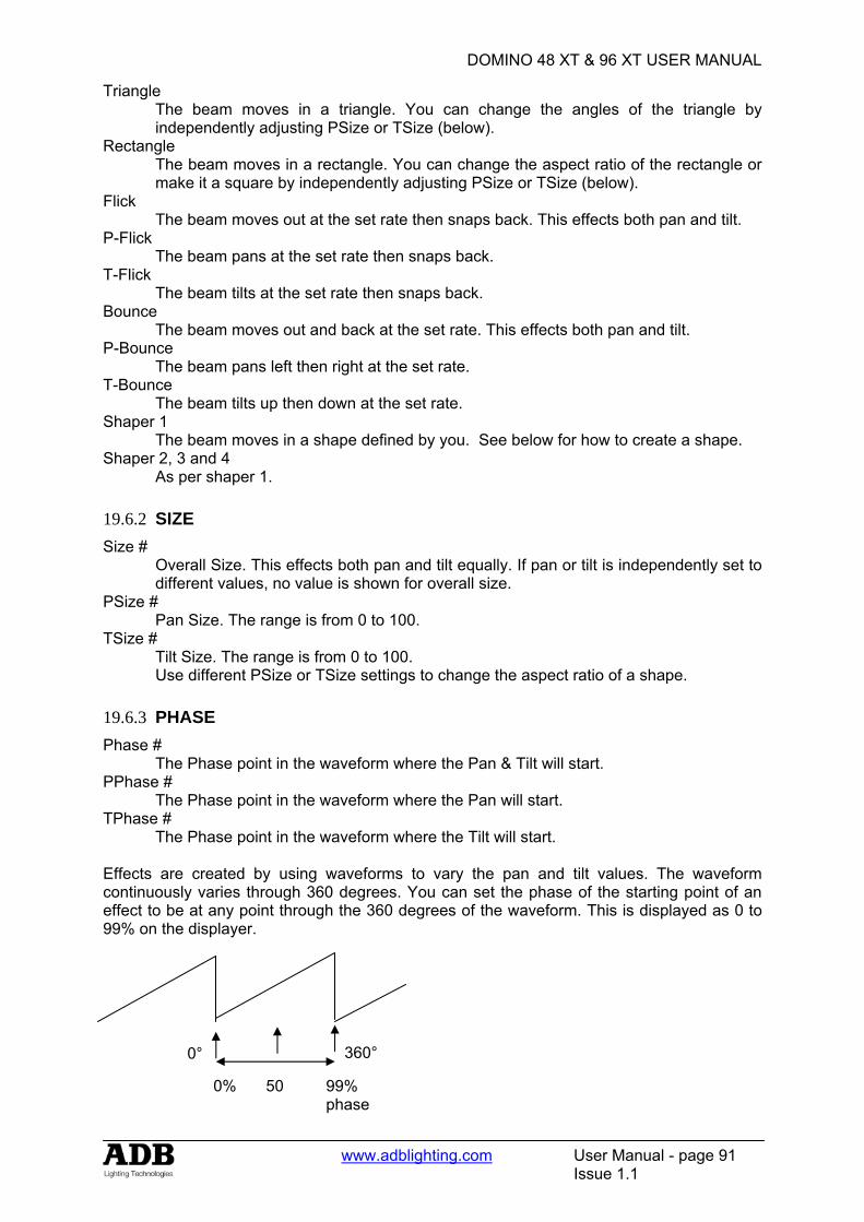
DOMINO 48 XT & 96 XT USER MANUAL
www.adblighting.com User Manual - page 91
Issue 1.1
Triangle The beam moves in a triangle. You can change the angles of the triangle by independently adjusting PSize or TSize (below).
Rectangle The beam moves in a rectangle. You can change the aspect ratio of the rectangle or make it a square by independently adjusting PSize or TSize (below).
Flick The beam moves out at the set rate then snaps back. This effects both pan and tilt.
P-Flick The beam pans at the set rate then snaps back.
T-Flick The beam tilts at the set rate then snaps back.
Bounce The beam moves out and back at the set rate. This effects both pan and tilt.
P-Bounce The beam pans left then right at the set rate.
T-Bounce The beam tilts up then down at the set rate.
Shaper 1 The beam moves in a shape defined by you. See below for how to create a shape.
Shaper 2, 3 and 4 As per shaper 1.
19.6.2 SIZE Size #
Overall Size. This effects both pan and tilt equally. If pan or tilt is independently set to different values, no value is shown for overall size.
PSize # Pan Size. The range is from 0 to 100.
TSize # Tilt Size. The range is from 0 to 100. Use different PSize or TSize settings to change the aspect ratio of a shape.
19.6.3 PHASE Phase #
The Phase point in the waveform where the Pan & Tilt will start. PPhase #
The Phase point in the waveform where the Pan will start. TPhase #
The Phase point in the waveform where the Tilt will start. Effects are created by using waveforms to vary the pan and tilt values. The waveform continuously varies through 360 degrees. You can set the phase of the starting point of an effect to be at any point through the 360 degrees of the waveform. This is displayed as 0 to 99% on the displayer.
360° 0°
50 99% phase
0%
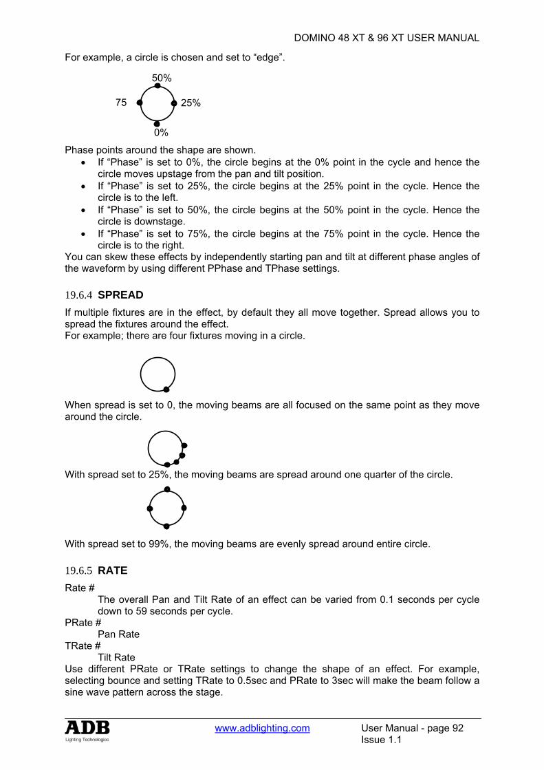
DOMINO 48 XT & 96 XT USER MANUAL
www.adblighting.com User Manual - page 92
Issue 1.1
For example, a circle is chosen and set to “edge”. Phase points around the shape are shown.
• If “Phase” is set to 0%, the circle begins at the 0% point in the cycle and hence the circle moves upstage from the pan and tilt position.
• If “Phase” is set to 25%, the circle begins at the 25% point in the cycle. Hence the circle is to the left.
• If “Phase” is set to 50%, the circle begins at the 50% point in the cycle. Hence the circle is downstage.
• If “Phase” is set to 75%, the circle begins at the 75% point in the cycle. Hence the circle is to the right.
You can skew these effects by independently starting pan and tilt at different phase angles of the waveform by using different PPhase and TPhase settings. 19.6.4 SPREAD If multiple fixtures are in the effect, by default they all move together. Spread allows you to spread the fixtures around the effect. For example; there are four fixtures moving in a circle. When spread is set to 0, the moving beams are all focused on the same point as they move around the circle. With spread set to 25%, the moving beams are spread around one quarter of the circle. With spread set to 99%, the moving beams are evenly spread around entire circle. 19.6.5 RATE Rate #
The overall Pan and Tilt Rate of an effect can be varied from 0.1 seconds per cycle down to 59 seconds per cycle.
PRate # Pan Rate
TRate # Tilt Rate
Use different PRate or TRate settings to change the shape of an effect. For example, selecting bounce and setting TRate to 0.5sec and PRate to 3sec will make the beam follow a sine wave pattern across the stage.
75 25%
50%
0%
DOMINO 48 XT & 96 XT USER MANUAL
www.adblighting.com User Manual - page 93
Issue 1.1
19.6.6 CYCLES Last #
This sets how many cycles of the effect oscillator will run until the effect stops. The count starts when a memory containing an effect is played back. The default is FF (FULL) meaning that the effect is continuous.
First # This sets the delay count of how many cycles the effect oscillator will run before the effect starts. The count starts when a memory containing an effect is played back. The default is 1 meaning the effect starts immediately.
19.6.7 CONTRL Start? (or Stop?)
Used to start or stop an effect. Tap the centre of the displayer to select. If the effect is running, the displayer will read “Stop?” If the effect is Stopped, the displayer will read “Start?”
Reverse? (or Forward?) Used to change the direction of an effect. Tap the centre of the displayer to select. If the effect is running forward, the displayer will read “Reverse?” If the effect is running reverse, the displayer will read “Forward?”
Edge? (or centre?) Tap the centre of the displayer to select. “Edge”. The effect passes through the current pan and tilt position. If “Edge” is active, the displayer will read “Centre?” “Centre”. The effect is centered around the current pan and tilt position. If “Centre” is active, the displayer will read “Edge?”
For example, if a circle shape is running; If “centre” is selected, the beam scribes a circle whose centre is the current pan and tilt position. If “edge” is selected, the beam leaves the current pan and tilts position, scribes a circle and returns to the same position. When “edge” is selected you can set the position of the effect (left, right, front, back) relative to the current beam position. See “Phase” above for details. Reset Resets all effect settings to default home values. 19.6.8 CUSTOM SHAPES Effects use waveforms to create the shapes that you see on stage. You can create 4 different custom shapes that can then be selected from the “Shape” menu. To create a custom shape, firstly reset to defaults to ensure that the effect is running continuously. Press [menu], [effects], [control] then tap the end of the displayer to show [reset?]. Press [reset?]. Select one of the 4 shaper waveforms as the current shape. Selecting a shape as the current effect lets you see the shape running live as you edit it. Press; [shape], then tap the ends of the displayer to select [shaper1]. To edit this shape, press; [control], then tap the ends of the displayer to show [editShp1?]. Press; [editShp1?]. Bank A faders 1 through 24 are used to form the shape of the pan waveform. Bank B faders 1 through 24 are used to form the shape of the tilt waveform. When a fader is in its mid position it has no effect. When it is set above or below its mid position it affects the parameter by a corresponding amount. Set Bank A faders 1 to 24 to mid position. The pan parameters will now be stationary.

DOMINO 48 XT & 96 XT USER MANUAL
www.adblighting.com User Manual - page 94
Issue 1.1
Set Bank B faders 1 to 24 to mid position. The tilt parameters will now be stationary. Adjust the faders into any shape of your choice. The fixtures respond in real time to the shapes that you create on the faders. You can make smooth changes by only having small variations between adjacent faders or you can make sudden movements by having large variations. To save the shape that you have created press; [closeShp1]. This shape is now available whenever you select [shaper1] from the shape menu. Create other shapes in shapers 2, 3 and 4 in a similar manner. As with any other shape, you can store many variations of a custom shape by using different settings of size, rate, phase etc. However, if you edit a custom shape, any stored effect that uses that shape will also be affected.
19.7 COPYING EFFECTS You can copy an effect that is running on a fixture to other fixtures of the same type.
• Hi-light the source fixture then select an effect from the effects menu and press [OK]. • Hi-light the source and destination fixtures. • Use the fixture displayer on the Moving light control module to select the source
fixture. • Press [menu], [effects].
The effect on the selected fixture is copied to all of the other hi-lighted fixtures of the same type
DOMINO 48 XT & 96 XT USER MANUAL
www.adblighting.com User Manual - page 95
Issue 1.1
20. FANS
20.1 OVERVIEW When you are controlling multiple fixtures on the Moving light control module you have the ability to manually make a fan (or spread) of settings across fixtures so that you get a symmetrical look. Typically you might individually adjust the pan parameters so that each fixture is focused on a common point or you might spread the fixtures out in a diverging pattern. Every fixture has to be individually adjusted which can be very time consuming. Moving light control module FANS automate this process by evenly spreading the parameter values to give you symmetrical looks at a touch of the Moving light control module. You typically positions all of you fixtures at a starting point, usually via the [home], [all] command, but it could be by playing back a memory that sends the fixtures to a known position. Press [menu], [fans] and instantly start to create stunning looks. You can individually fan the positions of pan and tilt. Fans can be symmetrical from the middle outwards or can start from either end. The order in which the fixtures are loaded onto the Moving light control module is used for the fanning order. You can save the fanning order as a group for later use. The fanning value can be adjusted in the positive or negative direction to give diverging or converging results. When you achieve the desired look, save the look as either a memory or a preset. FANS can also be used to quickly spread the move and delay times of fixtures. Memories recorded with fanned times can give you stunning movement effects when they are played back especially when fanned delay times are used. Fans can be combined with effects to quickly create amazing visual effects that would take hours to program manually.
20.2 FAN FUNCTIONS To create a fan, get the fixtures to be fanned onto the Moving light control module. If the fixtures exist in a group you can get the group.
Hint; to avoid confusion when fanning, clear the Moving light control module ([clear], [all]) before loading the fixtures to be fanned.
To select fans, press [menu], [FANs]. Fans can only be selected when there are 2 or more high-lighted fixtures of the same type on the Moving light control module. If you try to fan a single fixture then the message “ERR” (error) is shown on the fixture displayer. Press [menu] to cancel the “ERR” message. The following functions are available; F-Pan Position (Fan Pan Position) F-Tilt Position (Fan Tilt Position) F-Pan Mov (Fan Pan Move Time) F-Tilt Mov (Fan Tilt Move Time) F-Pan Dly (Fan Pan Delay Time) F-Tilt Dly (Fan Tilt Delay Time) To select a function press its displayer or the [PM] button beside it.
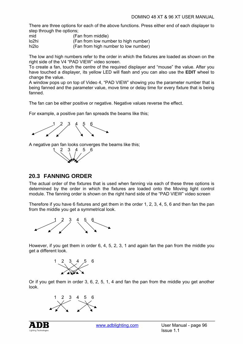
DOMINO 48 XT & 96 XT USER MANUAL
www.adblighting.com User Manual - page 96
Issue 1.1
There are three options for each of the above functions. Press either end of each displayer to step through the options; mid (Fan from middle) lo2hi (Fan from low number to high number) hi2lo (Fan from high number to low number) The low and high numbers refer to the order in which the fixtures are loaded as shown on the right side of the V4 “PAD VIEW” video screen. To create a fan, touch the centre of the required displayer and “mouse” the value. After you have touched a displayer, its yellow LED will flash and you can also use the EDIT wheel to change the value. A window pops up on top of Video 4, “PAD VIEW” showing you the parameter number that is being fanned and the parameter value, move time or delay time for every fixture that is being fanned. The fan can be either positive or negative. Negative values reverse the effect. For example, a positive pan fan spreads the beams like this; 1 2 3 4 5 6 A negative pan fan looks converges the beams like this; 1 2 3 4 5 6
20.3 FANNING ORDER The actual order of the fixtures that is used when fanning via each of these three options is determined by the order in which the fixtures are loaded onto the Moving light control module. The fanning order is shown on the right hand side of the “PAD VIEW” video screen Therefore if you have 6 fixtures and get them in the order 1, 2, 3, 4, 5, 6 and then fan the pan from the middle you get a symmetrical look. 1 2 3 4 5 6 However, if you get them in order 6, 4, 5, 2, 3, 1 and again fan the pan from the middle you get a different look. 1 2 3 4 5 6 Or if you get them in order 3, 6, 2, 5, 1, 4 and fan the pan from the middle you get another look. 1 2 3 4 5 6
DOMINO 48 XT & 96 XT USER MANUAL
www.adblighting.com User Manual - page 97
Issue 1.1
Hint: To rapidly get a range of fixtures onto the Moving light control module press and release [get]. HOLD [f/a] (first fixture in range), then tap [f/a] (last fixture in range). Both selected fixtures and all fixtures in between them are loaded. If you HOLD [f/a] (last fixture in range), then tap [f/a] (first fixture in range), the fixtures are loaded in reverse order.
20.4 STORING FAN ORDERS The order in which you get the fixtures can be saved as group. [store], [group], [f/a] (group number). When the group is loaded on the Moving light control module the stored order is recalled. To load the order you can use either; [get], [group], [f/a] (group number), (loads and hi-lights the group) or [group], [f/a] (group number) (highlights the already loaded fixtures in the group).
20.5 FANNING TIMES When you fan pan and tilt you see the results on stage. When you fan move and delay times, you must move the fixtures from a different (starting) focus position to the current focus position to see the fanned times executed. To do this, playback a memory that sends the fixtures to their starting position (a memory that you have already programmed) then press the [p-trig] button. This moves the fixtures to their Moving light control module positions using the fanned moving light control module times. For example, if you have an existing memory that focuses your fixtures “down stage” and you want to program a new memory with the fixtures focused “upstage” but with fanned Tilt delay times. Use the Moving light control module to focus the fixtures upstage and then use the fan menu to fan the tilt delay times. Before recording this new “upstage memory”, playback the existing “down stage” memory. This automatically saves the Moving light control module settings including the fanned tilt times. Playback the Moving light control module settings by pressing [p-trig] and the fixtures move upstage using the fanned tilt delay times. Make any time adjustments that you might need to the fanned times. Playback the “down stage” memory again (the adjusted times are saved). Press [p-trig] to see the same move with the new times. When the times are correct, save the new memory. When fanning times, the number shown in the displayer is only an indication of the amount of fan that has been applied. You can see the actual time values on the video screen (Video 4 PAD VIEW) as you adjust the fan.
20.6 SAVING FANS When you have made your fan, the fixture displayer reads “OK” and the [store] button flashes. You now have three choices; • To remove the fan and exit from the fan menu press [menu]. • To retain the fanned values and exit from the fan menu press [OK] on the fixture
displayer. The fanned values are entered into their fixtures parameters and you have created a look but it has not been saved as a memory. You can now use the Moving light control module to make other adjustments if necessary. If you select the fan menu again, you start to fan the current look (which is already fanned). Therefore all fan values (on the Moving light control module) will be back to zero as you are yet to begin fanning this look. The fan will be lost if any memory containing the parameters of the fixtures is played back.
DOMINO 48 XT & 96 XT USER MANUAL
www.adblighting.com User Manual - page 98
Issue 1.1
• To keep the fanned values, save it in a memory or a preset. The usual methods of saving are available. • To record the entire output press; [record memory], [page] (optional), [f/a] (memory
number). • To store only flashing parameters as a memory, press; [store], [page] (optional), [f/a]
(memory number). • To store only flashing parameters as a preset, press; [store], [preset],
[colour/beam/focus] (optional), [f/a] (preset number).
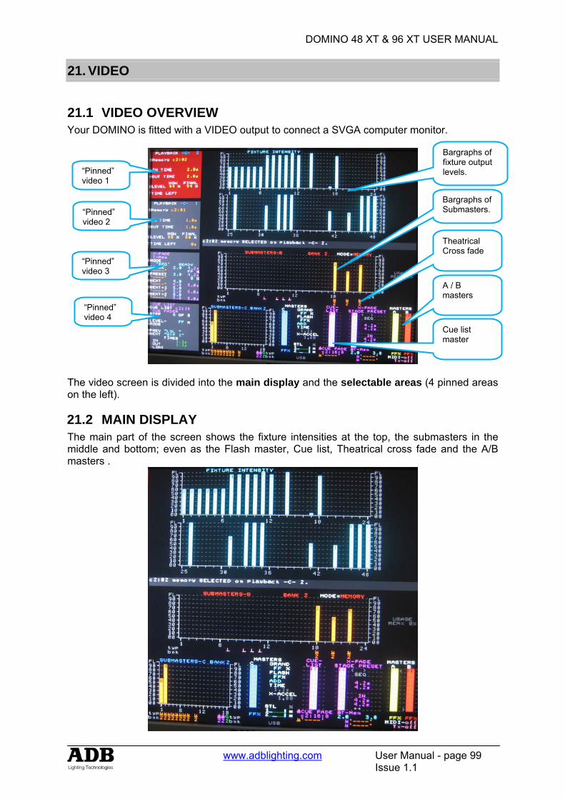
DOMINO 48 XT & 96 XT USER MANUAL
www.adblighting.com User Manual - page 99
Issue 1.1
21. VIDEO
21.1 VIDEO OVERVIEW Your DOMINO is fitted with a VIDEO output to connect a SVGA computer monitor.
The video screen is divided into the main display and the selectable areas (4 pinned areas on the left).
21.2 MAIN DISPLAY The main part of the screen shows the fixture intensities at the top, the submasters in the middle and bottom; even as the Flash master, Cue list, Theatrical cross fade and the A/B masters .
Bargraphs of fixture output levels. “Pinned”
video 1
“Pinned” video 4
Theatrical Cross fade
“Pinned” video 3
“Pinned” video 2
Bargraphs of Submasters.
A / B masters
Cue list master
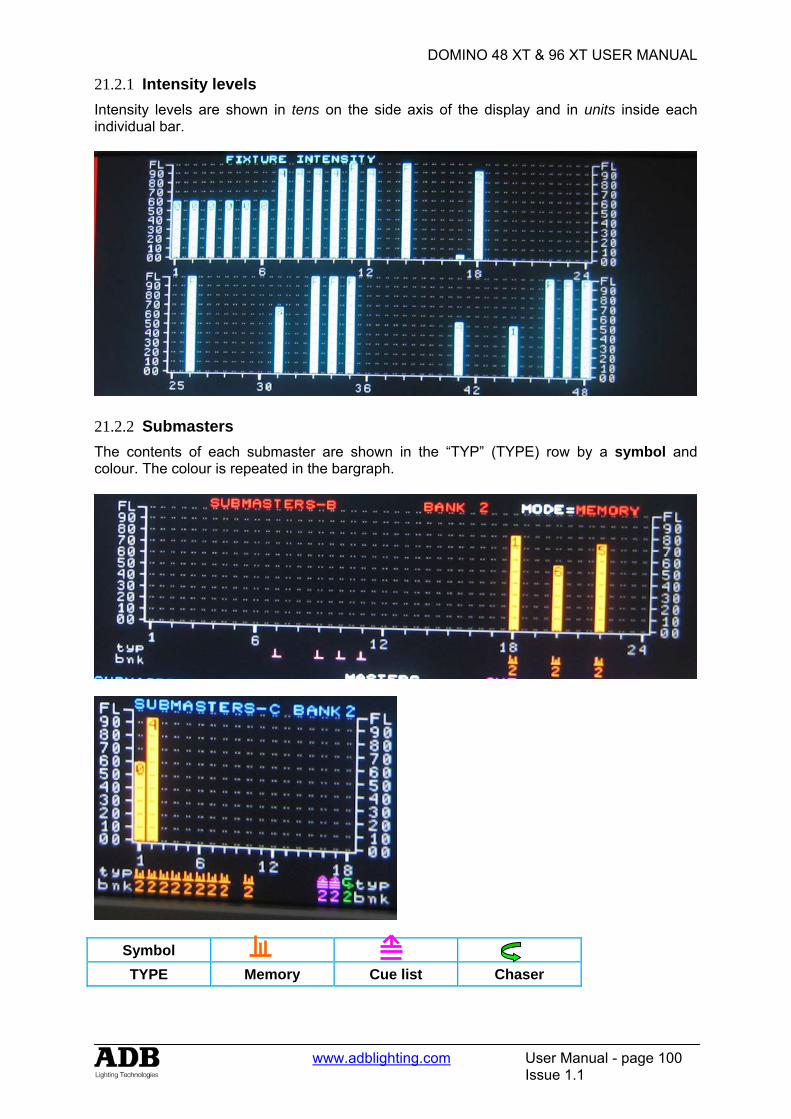
DOMINO 48 XT & 96 XT USER MANUAL
www.adblighting.com User Manual - page 100
Issue 1.1
21.2.1 Intensity levels Intensity levels are shown in tens on the side axis of the display and in units inside each individual bar.
21.2.2 Submasters The contents of each submaster are shown in the “TYP” (TYPE) row by a symbol and colour. The colour is repeated in the bargraph.
Symbol TYPE Memory Cue list Chaser
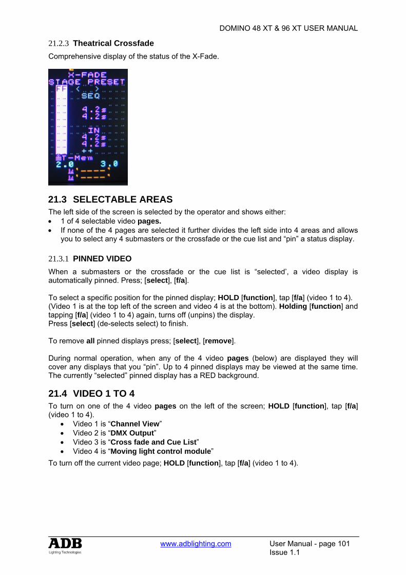
DOMINO 48 XT & 96 XT USER MANUAL
www.adblighting.com User Manual - page 101
Issue 1.1
21.2.3 Theatrical Crossfade Comprehensive display of the status of the X-Fade.
21.3 SELECTABLE AREAS The left side of the screen is selected by the operator and shows either: • 1 of 4 selectable video pages. • If none of the 4 pages are selected it further divides the left side into 4 areas and allows
you to select any 4 submasters or the crossfade or the cue list and “pin” a status display.
21.3.1 PINNED VIDEO When a submasters or the crossfade or the cue list is “selected’, a video display is automatically pinned. Press; [select], [f/a]. To select a specific position for the pinned display; HOLD [function], tap [f/a] (video 1 to 4). (Video 1 is at the top left of the screen and video 4 is at the bottom). Holding [function] and tapping [f/a] (video 1 to 4) again, turns off (unpins) the display. Press [select] (de-selects select) to finish. To remove all pinned displays press; [select], [remove]. During normal operation, when any of the 4 video pages (below) are displayed they will cover any displays that you “pin”. Up to 4 pinned displays may be viewed at the same time. The currently “selected” pinned display has a RED background.
21.4 VIDEO 1 TO 4 To turn on one of the 4 video pages on the left of the screen; HOLD [function], tap [f/a] (video 1 to 4).
• Video 1 is “Channel View” • Video 2 is “DMX Output” • Video 3 is “Cross fade and Cue List” • Video 4 is “Moving light control module”
To turn off the current video page; HOLD [function], tap [f/a] (video 1 to 4).
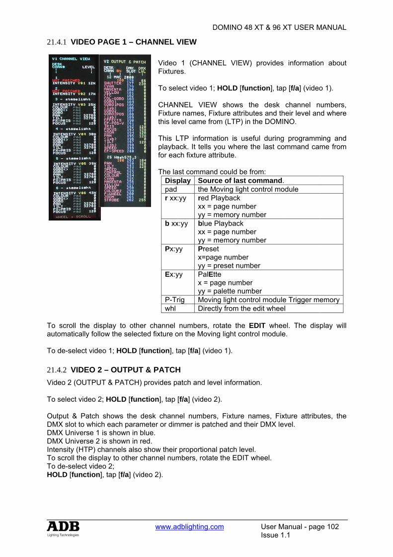
21.4.1 V
To scroautoma To de-s 21.4.2 VVideo 2 To sele Output DMX sloDMX UnDMX UnIntensityTo scroTo de-sHOLD [
VIDEO PA
oll the disptically follow
select video
VIDEO 2 –2 (OUTPUT
ct video 2; H
& Patch sot to which niverse 1 isniverse 2 isy (HTP) chall the displa
select video [function], t
AGE 1 – CH
play to othew the select
1; HOLD [f
– OUTPUT& PATCH)
HOLD [fun
hows the deach param
s shown in bs shown in rannels also ay to other c
2; tap [f/a] (vid
www.ad
HANNEL V Video Fixture To sel CHANFixturethis lev This Lplaybafor eac The la
Disppadr xx
b xx
Px:y
Ex:y
P-Trwhl
er channel ted fixture o
function], t
T & PATCHprovides p
ction], tap
desk channmeter or dimblue. red.
show their channel num
deo 2).
D
dblighting.c
VIEW
1 (CHANNes.
ect video 1
NNEL VIEWe names, Fvel came fro
LTP informaack. It tells ch fixture at
ast commanplay Sour
the M:yy red P
xx = yy =
x:yy blue xx = yy =
yy Presx=payy =
yy PalEx = pyy =
rig MoviDirec
numbers, on the Movin
tap [f/a] (vid
H atch and lev
[f/a] (video
nel numbermmer is patc
proportionambers, rotat
DOMINO 4
com
NEL VIEW
; HOLD [fu
W shows ixture attribom (LTP) in
ation is usyou where ttribute.
nd could be rce of last cMoving lightPlayback page numbmemory nuPlayback page numbmemory nuet
age numberpreset numtte
page numbepalette numng light conctly from the
rotate the ng light con
deo 1).
vel informat
2).
s, Fixture nched and th
al patch levete the EDIT
8 XT & 96 X
User MIssue 1
W) provides
nction], tap
the desk butes and thn the DOMI
eful duringthe last co
from: command.t control mo
ber umber
ber umber
rmber
er mber ntrol modulee edit whee
EDIT wheentrol module
tion.
names, Fixheir DMX lev
el. T wheel.
XT USER M
anual - pag.1
informatio
p [f/a] (video
channel nheir level anNO.
programmommand ca
odule
e Trigger ml
el. The dise.
xture attribuvel.
MANUAL
ge 102
n about
o 1).
numbers, nd where
ming and me from
emory
play will
utes, the
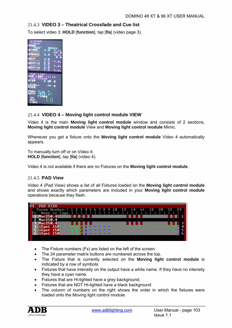
DOMINO 48 XT & 96 XT USER MANUAL
www.adblighting.com User Manual - page 103
Issue 1.1
21.4.3 VIDEO 3 – Theatrical Crossfade and Cue list To select video 3; HOLD [function], tap [f/a] (video page 3).
21.4.4 VIDEO 4 – Moving light control module VIEW Video 4 is the main Moving light control module window and consists of 2 sections, Moving light control module View and Moving light control module Mimic. Whenever you get a fixture onto the Moving light control module Video 4 automatically appears. To manually turn off or on Video 4; HOLD [function], tap [f/a] (video 4). Video 4 is not available if there are no Fixtures on the Moving light control module. 21.4.5 PAD View Video 4 (Pad View) shows a list of all Fixtures loaded on the Moving light control module and shows exactly which parameters are included in your Moving light control module operations because they flash.
• The Fixture numbers (Fx) are listed on the left of the screen. • The 24 parameter matrix buttons are numbered across the top. • The Fixture that is currently selected on the Moving light control module is
indicated by a row of symbols. • Fixtures that have intensity on the output have a white name. If they have no intensity
they have a cyan name. • Fixtures that are Hi-lighted have a grey background. • Fixtures that are NOT Hi-lighted have a black background • The column of numbers on the right shows the order in which the fixtures were
loaded onto the Moving light control module.
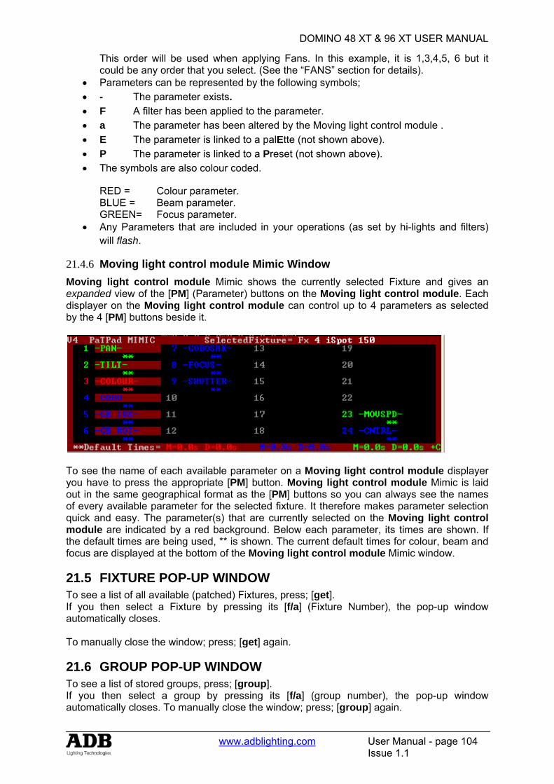
DOMINO 48 XT & 96 XT USER MANUAL
www.adblighting.com User Manual - page 104
Issue 1.1
This order will be used when applying Fans. In this example, it is 1,3,4,5, 6 but it could be any order that you select. (See the “FANS” section for details).
• Parameters can be represented by the following symbols; • - The parameter exists. • F A filter has been applied to the parameter. • a The parameter has been altered by the Moving light control module . • E The parameter is linked to a palEtte (not shown above). • P The parameter is linked to a Preset (not shown above). • The symbols are also colour coded.
RED = Colour parameter. BLUE = Beam parameter. GREEN= Focus parameter.
• Any Parameters that are included in your operations (as set by hi-lights and filters) will flash.
21.4.6 Moving light control module Mimic Window Moving light control module Mimic shows the currently selected Fixture and gives an expanded view of the [PM] (Parameter) buttons on the Moving light control module. Each displayer on the Moving light control module can control up to 4 parameters as selected by the 4 [PM] buttons beside it.
To see the name of each available parameter on a Moving light control module displayer you have to press the appropriate [PM] button. Moving light control module Mimic is laid out in the same geographical format as the [PM] buttons so you can always see the names of every available parameter for the selected fixture. It therefore makes parameter selection quick and easy. The parameter(s) that are currently selected on the Moving light control module are indicated by a red background. Below each parameter, its times are shown. If the default times are being used, ** is shown. The current default times for colour, beam and focus are displayed at the bottom of the Moving light control module Mimic window.
21.5 FIXTURE POP-UP WINDOW To see a list of all available (patched) Fixtures, press; [get]. If you then select a Fixture by pressing its [f/a] (Fixture Number), the pop-up window automatically closes. To manually close the window; press; [get] again.
21.6 GROUP POP-UP WINDOW To see a list of stored groups, press; [group]. If you then select a group by pressing its [f/a] (group number), the pop-up window automatically closes. To manually close the window; press; [group] again.
DOMINO 48 XT & 96 XT USER MANUAL
www.adblighting.com User Manual - page 105
Issue 1.1
21.7 PALETTE POP-UP WINDOW To see a list of stored palettes, press; [palette]. To step through the 4 palette pages repeatedly press; [colour/beam/focus]. If you select a palette by pressing its [f/a] (palette number), the pop-up window automatically closes. To manually close the window; press; [palette] again.
21.8 PRESET POP-UP WINDOW To see a list of stored presets, press; [preset]. To step through the 4 preset pages repeatedly press [colour/beam/focus]. If you select a preset by pressing its [f/a] (preset number), the pop-up window automatically closes. To manually close the window; press; [preset] again.
21.9 FILTER POP-UP WINDOW To see a list of all filter memories, press; [filter]. If you select a filter by pressing its [f/a] (filter number), the pop-up window automatically closes. To manually close the window; press; [filter] again.
21.10 PLAYBACK BANK MEMORIES To see a list of playback memories, HOLD either [page] button.
DOMINO 48 XT & 96 XT USER MANUAL
www.adblighting.com User Manual - page 106
Issue 1.1
22. STL (SOUND TO LIGHT) and SyncoBEAT
22.1 OVERVIEW The DOMINO has two identical STL (Sound To Light) processors called “stl 1” and “stl 2”. Each STL produces output pulses that can be “connected” to any submaster containing a chaser. When a STL is connected to a chaser, it will trigger a chaser step whenever there is a pulse on the STL output. Each STL has two modes of operation; • Sound to Light mode. The STL pulses are generated by the beat of the music
connected to the audio input of the DOMINO. • SyncoBEAT mode. The STL pulses are generated from a beat pattern that you teach. Each STL may be connected to any number of chasers. Both STL’s may be connected to the same chaser to give dual stepping control.
The “Beat” indicator on the video display always shows the stepping of the STL output pulses.
22.2 CONNECT STL TO CHASER An STL must be “connected” to a chaser to enable it to control the chaser stepping. There are 2 ways to connect the output of a STL to a chaser. 22.2.1 CONNECT TO SUBMASTER This method temporarily connects the STL to the selected Submaster. The recorded chaser is not changed, only the way that it is currently being played back. HOLD [function], tap [f/a] (stl 1) or (stl 2). HOLD [function] until the display reads “Pick”. Whilst still holding [function], tap [f/a] of the submaster(s) to be connected. • Submaster already connected to STL’s flash continuously. • Submasters NOT connected to STL’s flash, then pause, then flash again etc. If a submaster is already connected, tapping its [f/a] disconnects it. Press [edit] to finish. The submaster remains connected to the STL until the chaser is replaced on that submaster by either changing pages or changing the mode. 22.2.2 CONNECT TO CHASER. To permanently connect a STL to a chaser, whilst recording or editing a chaser, repeated presses of the [function] button will toggle the display between the STEP number, the SPEED and the CROSSFADE. When the STEP number is displayed; HOLD [function],tap either [stl 1] or [stl 2] (which are flashing). To connect the STL press [yes]. If the STL is already connected, pressing [yes] disconnects it. Finish recording or editing the chaser as described in the “CHASERS” section. The chaser remains connected to the STL unless it is “edited” to remove the connection.
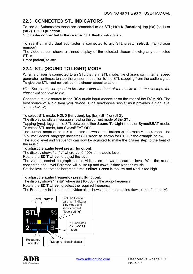
DOMINO 48 XT & 96 XT USER MANUAL
www.adblighting.com User Manual - page 107
Issue 1.1
22.3 CONNECTED STL INDICATORS To see all Submasters those are connected to an STL; HOLD [function], tap [f/a] (stl 1) or (stl 2). HOLD [function]. Submaster connected to the selected STL flash continuously. To see if an individual submaster is connected to any STL press; [select], [f/a] (chaser number). The video screen shows a pinned display of the selected chaser showing any connected STL’s. Press [select] to exit.
22.4 STL (SOUND TO LIGHT) MODE When a chaser is connected to an STL that is in STL mode, the chasers own internal speed generator continues to step the chaser in addition to the STL stepping from the audio signal. To give the STL total control, set the chaser speed to zero.
Hint; Set the chaser speed to be slower than the beat of the music. If the music stops, the chaser will continue to run.
Connect a music source to the RCA audio input connector on the rear of the DOMINO. The best source of audio from your device is the headphone socket as it provides a high level signal (1-2.5V). To select STL mode; HOLD [function], tap [f/a] (stl 1) or (stl 2). The display scrolls a message showing the current mode of the STL. Tapping [yes], toggles the STL between either Sound To Light mode or SyncoBEAT mode. To select STL mode, turn SyncoBEAT OFF. The current mode of each STL is also shown at the bottom of the main video screen. The ”Volume Control” bargraph indicates STL mode as shown for STL1 in the example below. The audio level and frequency can now be adjusted to make the chaser step to the beat of the music. To adjust the audio level press; [function]. The display shows “L: ##” where ## (0-100) is the audio level. Rotate the EDIT wheel to adjust the level. The volume control bargraph on the video also shows the current level. With the music connected, the Level Bargraph will pulse up and down in time with the music. Set the level so that the bargraph turns Yellow. Green is too low and Red is too high. To adjust the audio frequency press; [function]. The display shows “hz ##” where ## (10-600) is the audio frequency. Rotate the EDIT wheel to select the required frequency. The Frequency indicator on the video also shows the current setting (low to high frequency).
“Volume Control” bargraph indicates STL mode and shows current “level setting”.
“B” indicates SyncoBEAT mode
Frequency indicator
Level Bargraph
“Stepping” Beat indicator
DOMINO 48 XT & 96 XT USER MANUAL
www.adblighting.com User Manual - page 108
Issue 1.1
Select the audio frequency of the dominant beat in the music. Try a low frequency to pick up a bass guitar or set it higher to select a drum or cymbal.
Note: When you select a different frequency, the audio level of that frequency might be different from the previous frequency. You might need to repeat the “level” and “frequency” adjustments to get satisfactory stepping of your chaser.
When finished press; [edit]. To step a chaser with the STL you have created, the chase must be connected to the STL as described above.
22.5 SYNCOBEAT MODE SyncoBEAT allows you to teach the DOMINO a beat pattern that it will then repeat indefinitely. When a chaser is connected to an STL that is in SyncoBEAT mode, the chasers own internal speed generator is disconnected and the STL’s SyncoBEAT has total control of stepping. SyncoBEAT allows for a syncopated (non regular) pattern to be learned. You tap out a beat pattern and the DOMINO learns the pattern then repeats it indefinitely. A syncopated pattern allows you to have, for example some rapid steps followed by maybe a long pause and then steps getting faster or possibly slowing down. Any quantity from 1 to 20 beats can be entered in the beat pattern. To create a SyncoBEAT; HOLD [function], tap [f/a] (stl 1) or (stl 2). The display scrolls a message showing the current mode of the STL. Tapping [yes], toggles the STL between either Sound To Light mode or SyncoBEAT mode. Turn SyncoBEAT ON. The current mode of each STL is shown at the bottom of the video screen. The letter “B” indicates SyncoBEAT mode. To learn a beat pattern; HOLD [add] until the word “Learn” appears on the display. Whilst holding [add], enter your beat pattern by tapping [ok]. The beat pattern starts from the first tap of the [ok] button and ends when the [add] button is released. Remember that when the DOMINO repeats your beat pattern, the time between the last tap and the first tap is determined by the time between your last tap and when your release the [add] button. The “stepping beat indicator” on the video screen now moves to the beat that you have created. If the beat pattern is not correct, create a new SyncoBEAT pattern by holding [add] and repeating the procedure. The new pattern will replace the old pattern as soon as the [add] button is released. When the beat pattern is correct press; [edit] to exit. To step a chaser with the SyncoBEAT you have created, the chaser must be connected to the STL as described above. If a chaser has been set to “Single Shot Mode”, triggering the single shot will run the chaser once using the SyncoBEAT stepping. See the “CHASERS” section for more details on chases.
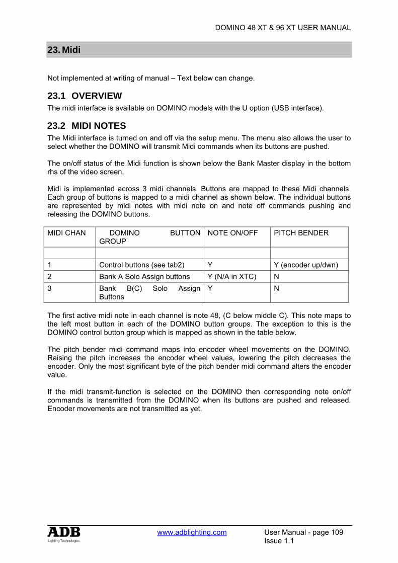
DOMINO 48 XT & 96 XT USER MANUAL
www.adblighting.com User Manual - page 109
Issue 1.1
23. Midi
Not implemented at writing of manual – Text below can change.
23.1 OVERVIEW The midi interface is available on DOMINO models with the U option (USB interface).
23.2 MIDI NOTES The Midi interface is turned on and off via the setup menu. The menu also allows the user to select whether the DOMINO will transmit Midi commands when its buttons are pushed.
The on/off status of the Midi function is shown below the Bank Master display in the bottom rhs of the video screen. Midi is implemented across 3 midi channels. Buttons are mapped to these Midi channels. Each group of buttons is mapped to a midi channel as shown below. The individual buttons are represented by midi notes with midi note on and note off commands pushing and releasing the DOMINO buttons. MIDI CHAN DOMINO BUTTON
GROUP NOTE ON/OFF PITCH BENDER
1 Control buttons (see tab2) Y Y (encoder up/dwn) 2 Bank A Solo Assign buttons Y (N/A in XTC) N 3 Bank B(C) Solo Assign
Buttons Y N
The first active midi note in each channel is note 48, (C below middle C). This note maps to the left most button in each of the DOMINO button groups. The exception to this is the DOMINO control button group which is mapped as shown in the table below. The pitch bender midi command maps into encoder wheel movements on the DOMINO. Raising the pitch increases the encoder wheel values, lowering the pitch decreases the encoder. Only the most significant byte of the pitch bender midi command alters the encoder value. If the midi transmit-function is selected on the DOMINO then corresponding note on/off commands is transmitted from the DOMINO when its buttons are pushed and released. Encoder movements are not transmitted as yet.
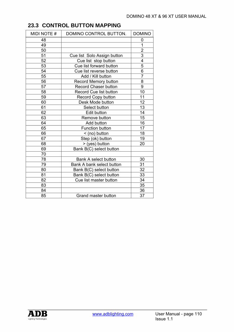
DOMINO 48 XT & 96 XT USER MANUAL
www.adblighting.com User Manual - page 110
Issue 1.1
23.3 CONTROL BUTTON MAPPING MIDI NOTE # DOMINO CONTROL BUTTON. DOMINO
48 0 49 1 50 2 51 Cue list Solo Assign button 3 52 Cue list stop button 4 53 Cue list forward button 5 54 Cue list reverse button 6 55 Add / Kill button 7 56 Record Memory button 8 57 Record Chaser button 9 58 Record Cue list button 10 59 Record Copy button 11 60 Desk Mode button 12 61 Select button 13 62 Edit button 14 63 Remove button 15 64 Add button 16 65 Function button 17 66 < (no) button 18 67 Step (ok) button 19 68 > (yes) button 20 69 Bank B(C) select button 70 78 Bank A select button 30 79 Bank A bank select button 31 80 Bank B(C) select button 32 81 Bank B(C) select button 33 82 Cue list master button 34 83 35 84 36 85 Grand master button 37
DOMINO 48 XT & 96 XT USER MANUAL
www.adblighting.com User Manual - page 111
Issue 1.1
24. UTILITIES
24.1 STORAGE OPERATIONS The DOMINO has an optional 2 USB ports. One port is dedicated for USB storage devices; the other USB port is dedicated for an external trackball (Motion control device). When you save or load a show from a USB device, you copy the entire contents of the DOMINO. This includes all Memories, Chasers, Cue lists, SyncoBEATs and the Patch. 24.1.1 SAVE SHOW To save a show to a USB device place the USB port then; HOLD [function], tap [f/a] (disk), [yes]. By default, the DOMINO offers a name of “SHOW1”. To accept the show number, press [ok]. To change the show number, rotate the EDIT wheel . Up to 9 show numbers may be used. To save the show number, press [ok], [yes]. When the save operation is complete press [ok].
Note: saving a show takes a few moments. During this time normal operation is not possible.
24.1.2 LOAD SHOW When you load a show from USB device, you replace the entire contents of the DOMINO with the show data from the disk.
WARNING: once a load from USB device is initiated, the current contents of the DOMINO will be erased and cannot be recovered.
To load a show from USB device; HOLD [function], tap [f/a] (disk), [no], [yes]. Rotate the EDIT wheel to select the show number. To load the show, press [ok], [yes]. When the load is complete press [ok].
Note: normal operation is not possible whilst a show is loading.
24.2 RESET The DOMINO provides two types of reset function. SYSTEM reset and TOTAL reset. 24.2.1 SYSTEM RESET In the unlikely event that the DOMINO fails to respond, the operating system may be reset so that the software may recommence normal operation. See also “POWER ON RESET” below. Performing a system reset selects “A/B” mode but will not affect any of the recorded submaster memory. To perform a SYSTEM RESET; HOLD [function], tap [f/a] (reset), [yes], [yes]. 24.2.2 TOTAL RESET Total Reset will ERASE all the recorded memory from the DOMINO and reset the operating system. See also “POWER ON RESET” below. To perform a TOTAL RESET HOLD [function], tap [f/a] (reset), [no], [yes], [yes]. 24.2.3 POWER ON RESETS If the DOMINO is not responding you will not be able to perform a reset as described above.
DOMINO 48 XT & 96 XT USER MANUAL
www.adblighting.com User Manual - page 112
Issue 1.1
In this case, switch off the DOMINO and wait for approximately 10 seconds then; • To perform a “system reset” at switch on; HOLD [function], switch on, release
[function]. • To perform a “TOTAL reset” at switch on (also known as a COLD START);
HOLD [no] + [yes], switch on the power and when the scrolling message finishes, release [no] + [yes].
24.3 MEMORY PROTECT The DOMINO can be locked to prevent unauthorised changes. Three levels of lock are available.
Hint: Always save your show before locking the DOMINO.
HOLD [function], tap [f/a] (set-up). The display asks “Lock Console?” • Lock PATCH. The patch cannot be edited • Lock SAVE. Memories cannot be saved or edited. • Lock All. The current DOMINO output continues but all controls are locked except for the
[function] button which is used to unlock the DOMINO You can select any of the three options by pressing its [PM] button. The selected option flashes. To accept the flashing option press;[yes]. The display scrolls “Enter Code”. Two levels of security are available: • For low level security without a code press [ok], [ok]. • For high level security use the channel B [f/a] buttons 1 to 9 (use 10 as 0) to enter a 1 to
4 digit lock code then press [ok]. Repeat the same digits then press [ok]. The console is now locked. 24.3.1 UNLOCK To unlock the DOMINO; HOLD [function], TAP [f/a] (set-up). The display asks “Unlock Console?”. Press [yes]. The display scrolls “Enter Code”. • If the console was locked with low level security simply press [ok]. • If the console was locked with high level security use channel B [f/a] buttons 1 to 9 (use
10 as 0) to enter the same digits used to lock the console then press [ok]. The console is now unlocked. 24.3.2 LOST LOCK CODE If you lock the DOMINO and forget the code you have two choices: 1. email [email protected] or contact your local ADB agent including the serial number of your DOMINO (located on the rear panel). An unlock code will be emailed to you (or your agent). 2. Perform a “Cold Start” which does a total reset and destroys ALL memories and show information. To perform a cold start, switch OFF the DOMINO and wait for 30 seconds. HOLD down the [yes] + [no] buttons and switch ON the DOMINO. Wait until the scrolling message finishes then release the two buttons.
24.4 MIDI Not implemented at writing of manual HOLD [function], tap [f/a] (setup), [no], [yes], [yes].
DOMINO 48 XT & 96 XT USER MANUAL
www.adblighting.com User Manual - page 113
Issue 1.1
24.5 SETUP PREFERENCES 24.5.1 DEFAULT FADE AND SPEED TIMES HOLD [function], tap [f/a] (setup), [no] [no], [yes], [yes]. Follow the prompts and set the times with the EDIT wheel . You can set default times for the following;
• Submaster memories - In time, Out time, Link time • Cue list - In time, Out time, Link time • Theatrical memory - In time, Out time, Link time • Chaser speed, X-fade
Cue list default In and Out times are only used if the step is a snapshot or a chaser. If the step is a submaster memory it will use its times. When a fade time is set lower than 0 seconds, it is controlled by the rotating speed fader. To accept the setting, press [ok].
24.6 LANGUAGE Not implemented at writing of manual To set the help language shown on the video display: HOLD [function], tap [f/a] (setup), [no], [no], [yes], [no], [yes]. Press [yes] or [no] to cycle through the available “Help Screen” languages as shown on the display. Current choices are English, French When your selected language is displayed press [yes].
24.7 DEFAULT FILE NAME To set the default name for saving shows; HOLD [function], tap [f/a] (setup), [no],[no] [yes], [no], [no], [yes]. Move the cursor with [<] or [>] and select characters the EDIT wheel . To save, press [ok].
24.8 B MASTER INVERTED The operation of the B master may be inverted so that its output is at minimum when the fader is at the bottom of its travel. To set the B Master inversion; HOLD [function], tap [f/a] (setup). The display asks “Lock Console?” Press [no]. The display asks “Midi?” Press [no]. The display asks “Set Preferences?” Press [yes], [no], [no], [no], [yes]. If the Master A is not inverted, the display asks “Master A is not inverted – Invert?” To invert it press [yes]. If the Master A is inverted, the display asks “Master A is inverted – Set Normal?” To set normal press [yes].
24.9 SOFTWARE UPGRADE 24.9.1 OVERVIEW The DOMINO operating system (firmware) can be upgraded via an USB device.
To upgrade your DOMINO you will also need the latest version of the DOMINO software. Notifications of new versions of the DOMINO software are posted on the adb website, download area.
DOMINO 48 XT & 96 XT USER MANUAL
www.adblighting.com User Manual - page 114
Issue 1.1
Each DOMINO model has its own version of the software. Note which model of DOMINO you are upgrading and select the correct one when you download the software from the web site. Before any software upgrade save any shows that you want to keep. Download the latest file and if available read the “read me” file for the latest instructions 24.9.2 USB DEVICE UPLOAD To upload a new firmware places the USB device in the USB port then; HOLD [function], tap [f/a] (disk),[no] [no] [yes]. Upgrade Desk, press [yes]. This will destroy all memories, continue? press [yes]. Upgrade version.... ? press [Yes] Checking upgrade file .... Upgrade takes 1 to 2 min. Yes when ready ? press [Yes] During upgrade the monitor will display nothing. After upgrade a reset complete is done, and the upgrade is finalised. 24.9.3 CODELINK If the DOMINO is not responding to the USB device (or you have no USB option) and you need to perform an update or reinstalling software; in that case you need to use the CODELINK Kit. If you do not have a CODELINK kit either contact ADB or an ADB distributor or you can download the software and instructions from the ADB website, www.adblighting.com .
24.10 DIAGNOSTICS The DOMINO provides diagnostics which allow you to; • Test the operation of all buttons, LEDS, faders, the EDIT wheel • Check internal battery voltage and charge condition. • Check memory capacity and usage.
24.10.1 DIAGNOSTICS MODE To select diagnostics mode; HOLD [function] tap [ok], release [function]. Several unlabelled Channel B [f/a] buttons flash to show they are active. 24.10.2 LED AND BUTTON TEST Enter diagnostics mode (above) then press channel B [f/a] (1). All LEDs should be lit. If a LED is not lit, then there is a possible problem with the LED. To test a button, press the button and its LED will go off. This indicates a command from that button has been received at the processor and it is operating correctly. To exit; HOLD [function], tap [ok]. 24.10.3 FADER TEST Enter diagnostics mode (above) then press channel B [f/a] (2). To test a fader, press the [f/a] button for that fader then move the fader. The display reads from 0 to 255 as the fader is moved through its range. To exit; HOLD [function], tap [ok]. 24.10.4 EDIT WHEEL TEST Enter diagnostics mode (above) then press channel B [f/a] (3)
DOMINO 48 XT & 96 XT USER MANUAL
www.adblighting.com User Manual - page 115
Issue 1.1
Rotate the EDIT wheel to test it. The display should smoothly count up or down as the wheel is rotated. To exit; HOLD [function], tap [ok]. 24.10.5 BATTERY TEST Enter diagnostics mode (above) then press channel B [f/a] (5). The display will show the battery voltage. It should be between approximately 5.8 and 6.4 volts. Press [ok]. The display will show the state of the battery as either, charging or charged. To exit, press [ok]. 24.10.6 SYSTEM ERROR INFORMATION Enter diagnostics mode (above) then press channel B [f/a] (10). The window pops up on the video screen show showing any system error information. In the event of any problems, this information can be conveyed to ADB to assist in fixing problems. To exit, press [ok]. 24.10.7 MEMORY TEST Enter diagnostics mode (above) then press channel A [f/a] (12). The display will show the percentage of memory used. Press [ok]. The display will show the percentage of heap used. (Internal ADB information). Press [ok]. The display will show the memory capacity fitted to the DOMINO. To exit, press [ok]. To exit diagnostics mode press [no].
DOMINO 48 XT & 96 XT USER MANUAL
www.adblighting.com User Manual - page 116
Issue 1.1
Notes


M-1183-E-01r
ADB - Your Partner for Light
Lighting Technologies
Subject to modifications
www.adblighting.com
Belgium N.V. ADB-TTV Technologies S.A.(Group Headquarters) Leuvensesteenweg 585, B-1930 ZaventemTel : +32.2.709.32.11, Fax : +32.2.709.32.80, E-Mail : [email protected]
France ADB S.A.S. Sales Office: 92, Avenue Jean Jaurès F-92120 MontrougeTel : +33.1.41.17.48.50, Fax : +33.1.42.53.54.76, E-Mail : [email protected]
Factory & Group Logistics Centre: Zone industrielle Rouvroy F-02100 Saint-QuentinTel : +33.3.23.06.35.70, Fax : +33.3.23.67.66.56, E-Mail : [email protected]