doodle (5.52mb)
TRANSCRIPT
To appear in the ACM SIGGRAPH conference proceedings
Motion Doodles: An Interface for Sketching Character Motion
Matthew Thorne David Burke
University of British Columbia∗
Michiel van de Panne
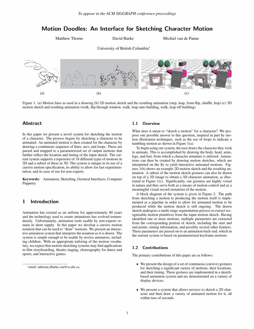
Figure 1: (a) Motion lines as used in a drawing (b) 2D motion sketch and the resulting animation (step, leap, front-flip, shuffle, hop) (c) 3Dmotion sketch and resulting animation (walk, flip through window, walk, leap onto building, walk, leap off building)
Abstract
In this paper we present a novel system for sketching the motionof a character. The process begins by sketching a character to beanimated. An animated motion is then created for the character bydrawing a continuous sequence of lines, arcs, and loops. These areparsed and mapped to a parameterized set of output motions thatfurther reflect the location and timing of the input sketch. The cur-rent system supports a repertoire of 18 different types of motions in2D and a subset of these in 3D. The system is unique in its use of acursive motion specification, its ability to allow for fast experimen-tation, and its ease of use for non-experts.
Keywords: Animation, Sketching, Gestural Interfaces, ComputerPuppetry
1 Introduction
Animation has existed as an artform for approximately 80 yearsand the technology used to create animations has evolved tremen-dously. Unfortunately, animation tools usable by non-experts re-main in short supply. In this paper we develop a cursive motionnotation that can be used to “draw” motions. We present an interac-tive animation system that interprets the notation as it is drawn. Thesystem is simple enough to be usable by novice animators, includ-ing children. With an appropriate tailoring of the motion vocabu-lary, we expect that motion sketching systems may find applicationsin film storyboarding, theatre staging, choreography for dance andsports, and interactive games.
∗email: mthorne,dburke,[email protected]
1.1 Overview
What does it mean to “sketch a motion” for a character? We pro-pose one possible answer to this question, inspired in part by mo-tion illustration techniques, such as the use of loops to indicate atumbling motion as shown in Figure 1(a).
To begin using our system, the user draws the character they wishto animate. This is accomplished by drawing the body, head, arms,legs, and feet, from which a character armature is inferred. Anima-tions can then be created by drawing motion sketches, which areinterpreted on the fly to yield interactive animated motions. Fig-ures 1(b) shows an example 2D motion sketch and the resulting an-imation. A subset of the motion sketch gestures can also be drawnon top of a 3D image to obtain a 3D character animation, as illus-trated in Figure 1(c). Significantly, our gestures are highly visualin nature and thus serve both as a means of motion control and as ameaningful visual record (notation) of the motion.
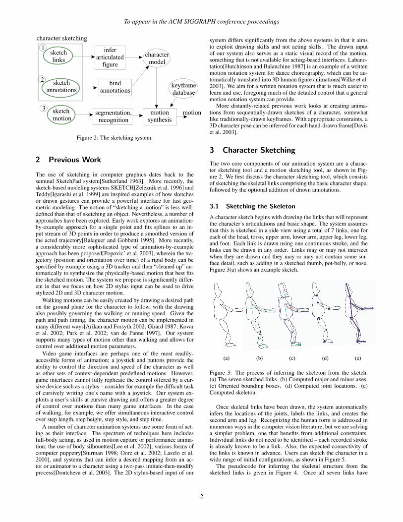
A block diagram of the system is given in Figure 2. The pathfrom sketching a motion to producing the motion itself is imple-mented as a pipeline in order to allow for animated motion to beproduced while the motion sketch is still ongoing. The drawnsketch undergoes a multi-stage segmentation process to extract rec-ognizable motion primitives from the input motion sketch. Havingidentified one or more motions, multiple parameters are extractedfrom the corresponding portion of sketch, including the start andend points, timing information, and possibly several other features.These parameters are passed on to an animation back-end, which inthe current system is based on parameterized keyframe motions.
1.2 Contributions
The primary contributions of this paper are as follows:
• We present the design of a set of continuous (cursive) gesturesfor sketching a significant variety of motions, their locations,and their timing. These gestures are implemented in a sketch-based animation system and are demonstrated on a variety ofdisplay devices.
• We present a system that allows novices to sketch a 2D char-acter and then draw a variety of animated motion for it, allwithin tens of seconds.
1
To appear in the ACM SIGGRAPH conference proceedings
Figure 2: The sketching system.
2 Previous Work
The use of sketching in computer graphics dates back to theseminal SketchPad system[Sutherland 1963]. More recently, thesketch-based modeling systems SKETCH[Zeleznik et al. 1996] andTeddy[Igarashi et al. 1999] are inspired examples of how sketchesor drawn gestures can provide a powerful interface for fast geo-metric modeling. The notion of “sketching a motion” is less well-defined than that of sketching an object. Nevertheless, a number ofapproaches have been explored. Early work explores an animation-by-example approach for a single point and fits splines to an in-put stream of 3D points in order to produce a smoothed version ofthe acted trajectory[Balaguer and Gobbetti 1995]. More recently,a considerably more sophisticated type of animation-by-exampleapproach has been proposed[Popovic’ et al. 2003], wherein the tra-jectory (position and orientation over time) of a rigid body can bespecified by example using a 3D tracker and then “cleaned up” au-tomatically to synthesize the physically-based motion that best fitsthe sketched motion. The system we propose is significantly differ-ent in that we focus on how 2D stylus input can be used to drivestylized 2D and 3D character motion.
Walking motions can be easily created by drawing a desired pathon the ground plane for the character to follow, with the drawingalso possibly governing the walking or running speed. Given thepath and path timing, the character motion can be implemented inmany different ways[Arikan and Forsyth 2002; Girard 1987; Kovaret al. 2002; Park et al. 2002; van de Panne 1997]. Our systemsupports many types of motion other than walking and allows forcontrol over additional motion parameters.
Video game interfaces are perhaps one of the most readily-accessible forms of animation; a joystick and buttons provide theability to control the direction and speed of the character as wellas other sets of context-dependent predefined motions. However,game interfaces cannot fully replicate the control offered by a cur-sive device such as a stylus – consider for example the difficult taskof cursively writing one’s name with a joystick. Our system ex-ploits a user’s skills at cursive drawing and offers a greater degreeof control over motions than many game interfaces. In the caseof walking, for example, we offer simultaneous interactive controlover step length, step height, step style, and step time.
A number of character animation systems use some form of act-ing as their interface. The spectrum of techniques here includesfull-body acting, as used in motion capture or performance anima-tion; the use of body silhouettes[Lee et al. 2002], various forms ofcomputer puppetry[Sturman 1998; Oore et al. 2002; Laszlo et al.2000], and systems that can infer a desired mapping from an ac-tor or animator to a character using a two-pass imitate-then-modifyprocess[Dontcheva et al. 2003]. The 2D stylus-based input of our
system differs significantly from the above systems in that it aimsto exploit drawing skills and not acting skills. The drawn inputof our system also serves as a static visual record of the motion,something that is not available for acting-based interfaces. Labano-tation[Hutchinson and Balanchine 1987] is an example of a writtenmotion notation system for dance choreography, which can be au-tomatically translated into 3D human figure animations[Wilke et al.2003]. We aim for a written notation system that is much easier tolearn and use, foregoing much of the detailed control that a generalmotion notation system can provide.
More distantly-related previous work looks at creating anima-tions from sequentially-drawn sketches of a character, somewhatlike traditionally-drawn keyframes. With appropriate constraints, a3D character pose can be inferred for each hand-drawn frame[Daviset al. 2003].
3 Character Sketching
The two core components of our animation system are a charac-ter sketching tool and a motion sketching tool, as shown in Fig-ure 2. We first discuss the character sketching tool, which consistsof sketching the skeletal links comprising the basic character shape,followed by the optional addition of drawn annotations.
3.1 Sketching the Skeleton
A character sketch begins with drawing the links that will representthe character’s articulations and basic shape. The system assumesthat this is sketched in a side view using a total of 7 links, one foreach of the head, torso, upper arm, lower arm, upper leg, lower leg,and foot. Each link is drawn using one continuous stroke, and thelinks can be drawn in any order. Links may or may not intersectwhen they are drawn and they may or may not contain some sur-face detail, such as adding in a sketched thumb, pot-belly, or nose.Figure 3(a) shows an example sketch.
Figure 3: The process of inferring the skeleton from the sketch.(a) The seven sketched links. (b) Computed major and minor axes.(c) Oriented bounding boxes. (d) Computed joint locations. (e)Computed skeleton.
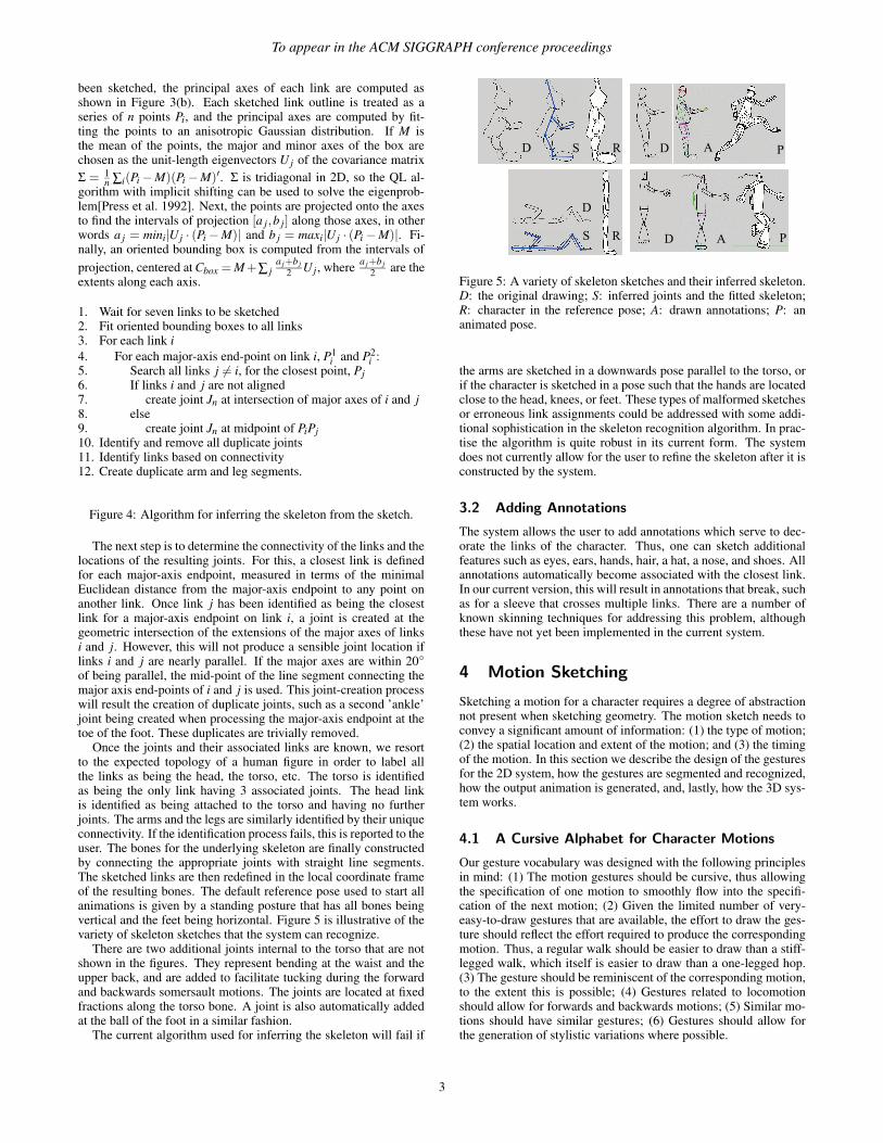
Once skeletal links have been drawn, the system automaticallyinfers the locations of the joints, labels the links, and creates thesecond arm and leg. Recognizing the human form is addressed innumerous ways in the computer vision literature, but we are solvinga simpler problem, one that benefits from additional constraints.Individual links do not need to be identified – each recorded strokeis already known to be a link. Also, the expected connectivity ofthe links is known in advance. Users can sketch the character in awide range of initial configurations, as shown in Figure 5.
The pseudocode for inferring the skeletal structure from thesketched links is given in Figure 4. Once all seven links have
2
To appear in the ACM SIGGRAPH conference proceedings
been sketched, the principal axes of each link are computed asshown in Figure 3(b). Each sketched link outline is treated as aseries of n points Pi, and the principal axes are computed by fit-ting the points to an anisotropic Gaussian distribution. If M isthe mean of the points, the major and minor axes of the box arechosen as the unit-length eigenvectors U j of the covariance matrixΣ = 1
n ∑i(Pi −M)(Pi −M)′. Σ is tridiagonal in 2D, so the QL al-gorithm with implicit shifting can be used to solve the eigenprob-lem[Press et al. 1992]. Next, the points are projected onto the axesto find the intervals of projection [a j,b j] along those axes, in otherwords a j = mini|U j · (Pi −M)| and b j = maxi|U j · (Pi −M)|. Fi-nally, an oriented bounding box is computed from the intervals ofprojection, centered at Cbox = M +∑ j
a j+b j2 U j , where a j+b j
2 are theextents along each axis.
1. Wait for seven links to be sketched2. Fit oriented bounding boxes to all links3. For each link i4. For each major-axis end-point on link i, P1
i and P2i :
5. Search all links j 6= i, for the closest point, Pj6. If links i and j are not aligned7. create joint Jn at intersection of major axes of i and j8. else9. create joint Jn at midpoint of PiPj10. Identify and remove all duplicate joints11. Identify links based on connectivity12. Create duplicate arm and leg segments.
Figure 4: Algorithm for inferring the skeleton from the sketch.
The next step is to determine the connectivity of the links and thelocations of the resulting joints. For this, a closest link is definedfor each major-axis endpoint, measured in terms of the minimalEuclidean distance from the major-axis endpoint to any point onanother link. Once link j has been identified as being the closestlink for a major-axis endpoint on link i, a joint is created at thegeometric intersection of the extensions of the major axes of linksi and j. However, this will not produce a sensible joint location iflinks i and j are nearly parallel. If the major axes are within 20◦of being parallel, the mid-point of the line segment connecting themajor axis end-points of i and j is used. This joint-creation processwill result the creation of duplicate joints, such as a second ’ankle’joint being created when processing the major-axis endpoint at thetoe of the foot. These duplicates are trivially removed.
Once the joints and their associated links are known, we resortto the expected topology of a human figure in order to label allthe links as being the head, the torso, etc. The torso is identifiedas being the only link having 3 associated joints. The head linkis identified as being attached to the torso and having no furtherjoints. The arms and the legs are similarly identified by their uniqueconnectivity. If the identification process fails, this is reported to theuser. The bones for the underlying skeleton are finally constructedby connecting the appropriate joints with straight line segments.The sketched links are then redefined in the local coordinate frameof the resulting bones. The default reference pose used to start allanimations is given by a standing posture that has all bones beingvertical and the feet being horizontal. Figure 5 is illustrative of thevariety of skeleton sketches that the system can recognize.
There are two additional joints internal to the torso that are notshown in the figures. They represent bending at the waist and theupper back, and are added to facilitate tucking during the forwardand backwards somersault motions. The joints are located at fixedfractions along the torso bone. A joint is also automatically addedat the ball of the foot in a similar fashion.
The current algorithm used for inferring the skeleton will fail if
Figure 5: A variety of skeleton sketches and their inferred skeleton.D: the original drawing; S: inferred joints and the fitted skeleton;R: character in the reference pose; A: drawn annotations; P: ananimated pose.
the arms are sketched in a downwards pose parallel to the torso, orif the character is sketched in a pose such that the hands are locatedclose to the head, knees, or feet. These types of malformed sketchesor erroneous link assignments could be addressed with some addi-tional sophistication in the skeleton recognition algorithm. In prac-tise the algorithm is quite robust in its current form. The systemdoes not currently allow for the user to refine the skeleton after it isconstructed by the system.
3.2 Adding Annotations
The system allows the user to add annotations which serve to dec-orate the links of the character. Thus, one can sketch additionalfeatures such as eyes, ears, hands, hair, a hat, a nose, and shoes. Allannotations automatically become associated with the closest link.In our current version, this will result in annotations that break, suchas for a sleeve that crosses multiple links. There are a number ofknown skinning techniques for addressing this problem, althoughthese have not yet been implemented in the current system.
4 Motion Sketching
Sketching a motion for a character requires a degree of abstractionnot present when sketching geometry. The motion sketch needs toconvey a significant amount of information: (1) the type of motion;(2) the spatial location and extent of the motion; and (3) the timingof the motion. In this section we describe the design of the gesturesfor the 2D system, how the gestures are segmented and recognized,how the output animation is generated, and, lastly, how the 3D sys-tem works.
4.1 A Cursive Alphabet for Character Motions
Our gesture vocabulary was designed with the following principlesin mind: (1) The motion gestures should be cursive, thus allowingthe specification of one motion to smoothly flow into the specifi-cation of the next motion; (2) Given the limited number of very-easy-to-draw gestures that are available, the effort to draw the ges-ture should reflect the effort required to produce the correspondingmotion. Thus, a regular walk should be easier to draw than a stiff-legged walk, which itself is easier to draw than a one-legged hop.(3) The gesture should be reminiscent of the corresponding motion,to the extent this is possible; (4) Gestures related to locomotionshould allow for forwards and backwards motions; (5) Similar mo-tions should have similar gestures; (6) Gestures should allow forthe generation of stylistic variations where possible.
3
To appear in the ACM SIGGRAPH conference proceedings
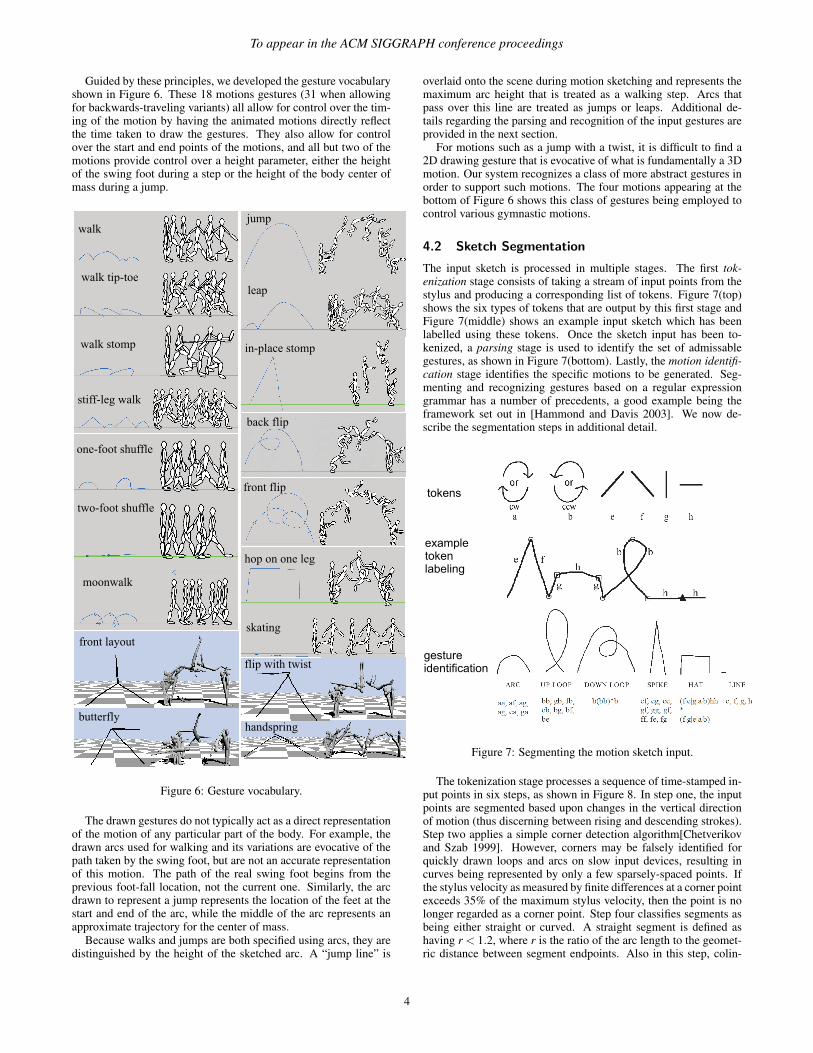
Guided by these principles, we developed the gesture vocabularyshown in Figure 6. These 18 motions gestures (31 when allowingfor backwards-traveling variants) all allow for control over the tim-ing of the motion by having the animated motions directly reflectthe time taken to draw the gestures. They also allow for controlover the start and end points of the motions, and all but two of themotions provide control over a height parameter, either the heightof the swing foot during a step or the height of the body center ofmass during a jump.
Figure 6: Gesture vocabulary.
The drawn gestures do not typically act as a direct representationof the motion of any particular part of the body. For example, thedrawn arcs used for walking and its variations are evocative of thepath taken by the swing foot, but are not an accurate representationof this motion. The path of the real swing foot begins from theprevious foot-fall location, not the current one. Similarly, the arcdrawn to represent a jump represents the location of the feet at thestart and end of the arc, while the middle of the arc represents anapproximate trajectory for the center of mass.
Because walks and jumps are both specified using arcs, they aredistinguished by the height of the sketched arc. A “jump line” is
overlaid onto the scene during motion sketching and represents themaximum arc height that is treated as a walking step. Arcs thatpass over this line are treated as jumps or leaps. Additional de-tails regarding the parsing and recognition of the input gestures areprovided in the next section.
For motions such as a jump with a twist, it is difficult to find a2D drawing gesture that is evocative of what is fundamentally a 3Dmotion. Our system recognizes a class of more abstract gestures inorder to support such motions. The four motions appearing at thebottom of Figure 6 shows this class of gestures being employed tocontrol various gymnastic motions.
4.2 Sketch Segmentation
The input sketch is processed in multiple stages. The first tok-enization stage consists of taking a stream of input points from thestylus and producing a corresponding list of tokens. Figure 7(top)shows the six types of tokens that are output by this first stage andFigure 7(middle) shows an example input sketch which has beenlabelled using these tokens. Once the sketch input has been to-kenized, a parsing stage is used to identify the set of admissablegestures, as shown in Figure 7(bottom). Lastly, the motion identifi-cation stage identifies the specific motions to be generated. Seg-menting and recognizing gestures based on a regular expressiongrammar has a number of precedents, a good example being theframework set out in [Hammond and Davis 2003]. We now de-scribe the segmentation steps in additional detail.
Figure 7: Segmenting the motion sketch input.
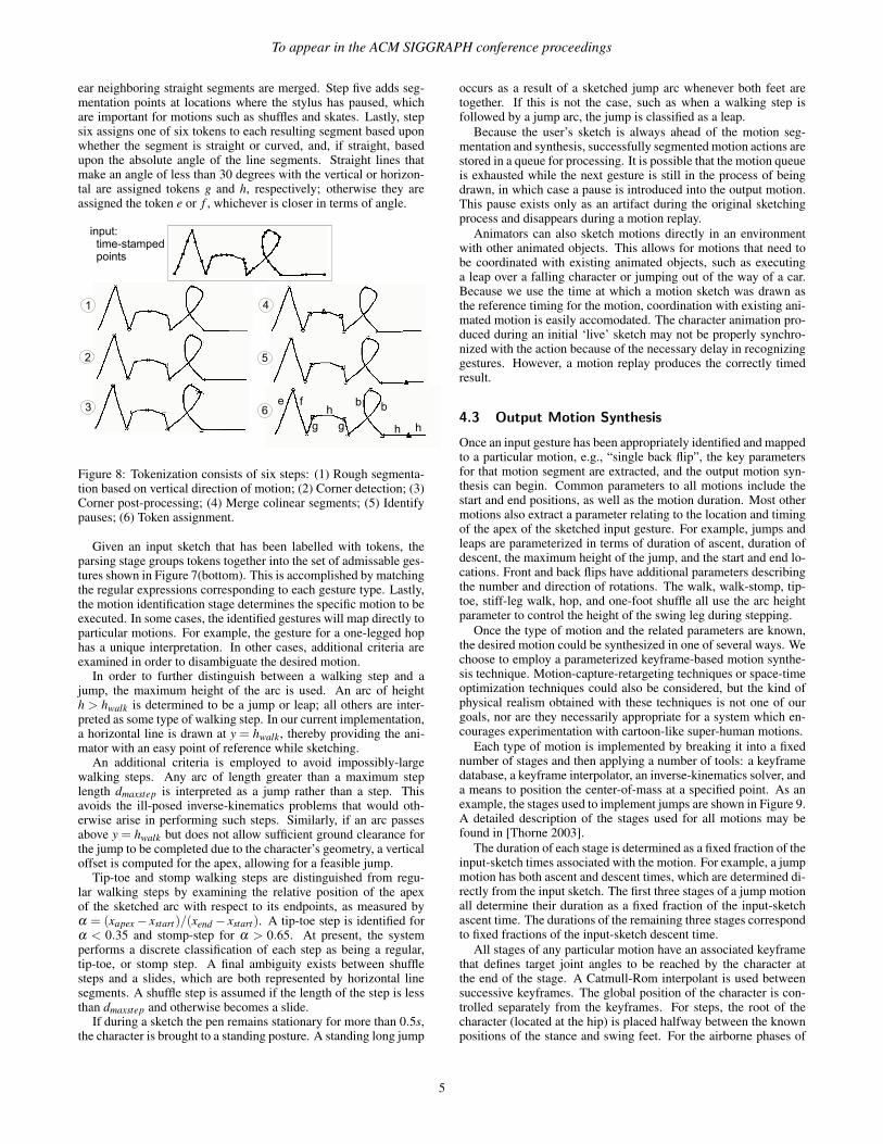
The tokenization stage processes a sequence of time-stamped in-put points in six steps, as shown in Figure 8. In step one, the inputpoints are segmented based upon changes in the vertical directionof motion (thus discerning between rising and descending strokes).Step two applies a simple corner detection algorithm[Chetverikovand Szab 1999]. However, corners may be falsely identified forquickly drawn loops and arcs on slow input devices, resulting incurves being represented by only a few sparsely-spaced points. Ifthe stylus velocity as measured by finite differences at a corner pointexceeds 35% of the maximum stylus velocity, then the point is nolonger regarded as a corner point. Step four classifies segments asbeing either straight or curved. A straight segment is defined ashaving r < 1.2, where r is the ratio of the arc length to the geomet-ric distance between segment endpoints. Also in this step, colin-
4
To appear in the ACM SIGGRAPH conference proceedings
ear neighboring straight segments are merged. Step five adds seg-mentation points at locations where the stylus has paused, whichare important for motions such as shuffles and skates. Lastly, stepsix assigns one of six tokens to each resulting segment based uponwhether the segment is straight or curved, and, if straight, basedupon the absolute angle of the line segments. Straight lines thatmake an angle of less than 30 degrees with the vertical or horizon-tal are assigned tokens g and h, respectively; otherwise they areassigned the token e or f , whichever is closer in terms of angle.
Figure 8: Tokenization consists of six steps: (1) Rough segmenta-tion based on vertical direction of motion; (2) Corner detection; (3)Corner post-processing; (4) Merge colinear segments; (5) Identifypauses; (6) Token assignment.
Given an input sketch that has been labelled with tokens, theparsing stage groups tokens together into the set of admissable ges-tures shown in Figure 7(bottom). This is accomplished by matchingthe regular expressions corresponding to each gesture type. Lastly,the motion identification stage determines the specific motion to beexecuted. In some cases, the identified gestures will map directly toparticular motions. For example, the gesture for a one-legged hophas a unique interpretation. In other cases, additional criteria areexamined in order to disambiguate the desired motion.
In order to further distinguish between a walking step and ajump, the maximum height of the arc is used. An arc of heighth > hwalk is determined to be a jump or leap; all others are inter-preted as some type of walking step. In our current implementation,a horizontal line is drawn at y = hwalk, thereby providing the ani-mator with an easy point of reference while sketching.
An additional criteria is employed to avoid impossibly-largewalking steps. Any arc of length greater than a maximum steplength dmaxstep is interpreted as a jump rather than a step. Thisavoids the ill-posed inverse-kinematics problems that would oth-erwise arise in performing such steps. Similarly, if an arc passesabove y = hwalk but does not allow sufficient ground clearance forthe jump to be completed due to the character’s geometry, a verticaloffset is computed for the apex, allowing for a feasible jump.
Tip-toe and stomp walking steps are distinguished from regu-lar walking steps by examining the relative position of the apexof the sketched arc with respect to its endpoints, as measured byα = (xapex − xstart)/(xend − xstart). A tip-toe step is identified forα < 0.35 and stomp-step for α > 0.65. At present, the systemperforms a discrete classification of each step as being a regular,tip-toe, or stomp step. A final ambiguity exists between shufflesteps and a slides, which are both represented by horizontal linesegments. A shuffle step is assumed if the length of the step is lessthan dmaxstep and otherwise becomes a slide.
If during a sketch the pen remains stationary for more than 0.5s,the character is brought to a standing posture. A standing long jump
occurs as a result of a sketched jump arc whenever both feet aretogether. If this is not the case, such as when a walking step isfollowed by a jump arc, the jump is classified as a leap.
Because the user’s sketch is always ahead of the motion seg-mentation and synthesis, successfully segmented motion actions arestored in a queue for processing. It is possible that the motion queueis exhausted while the next gesture is still in the process of beingdrawn, in which case a pause is introduced into the output motion.This pause exists only as an artifact during the original sketchingprocess and disappears during a motion replay.
Animators can also sketch motions directly in an environmentwith other animated objects. This allows for motions that need tobe coordinated with existing animated objects, such as executinga leap over a falling character or jumping out of the way of a car.Because we use the time at which a motion sketch was drawn asthe reference timing for the motion, coordination with existing ani-mated motion is easily accomodated. The character animation pro-duced during an initial ‘live’ sketch may not be properly synchro-nized with the action because of the necessary delay in recognizinggestures. However, a motion replay produces the correctly timedresult.
4.3 Output Motion Synthesis
Once an input gesture has been appropriately identified and mappedto a particular motion, e.g., “single back flip”, the key parametersfor that motion segment are extracted, and the output motion syn-thesis can begin. Common parameters to all motions include thestart and end positions, as well as the motion duration. Most othermotions also extract a parameter relating to the location and timingof the apex of the sketched input gesture. For example, jumps andleaps are parameterized in terms of duration of ascent, duration ofdescent, the maximum height of the jump, and the start and end lo-cations. Front and back flips have additional parameters describingthe number and direction of rotations. The walk, walk-stomp, tip-toe, stiff-leg walk, hop, and one-foot shuffle all use the arc heightparameter to control the height of the swing leg during stepping.
Once the type of motion and the related parameters are known,the desired motion could be synthesized in one of several ways. Wechoose to employ a parameterized keyframe-based motion synthe-sis technique. Motion-capture-retargeting techniques or space-timeoptimization techniques could also be considered, but the kind ofphysical realism obtained with these techniques is not one of ourgoals, nor are they necessarily appropriate for a system which en-courages experimentation with cartoon-like super-human motions.
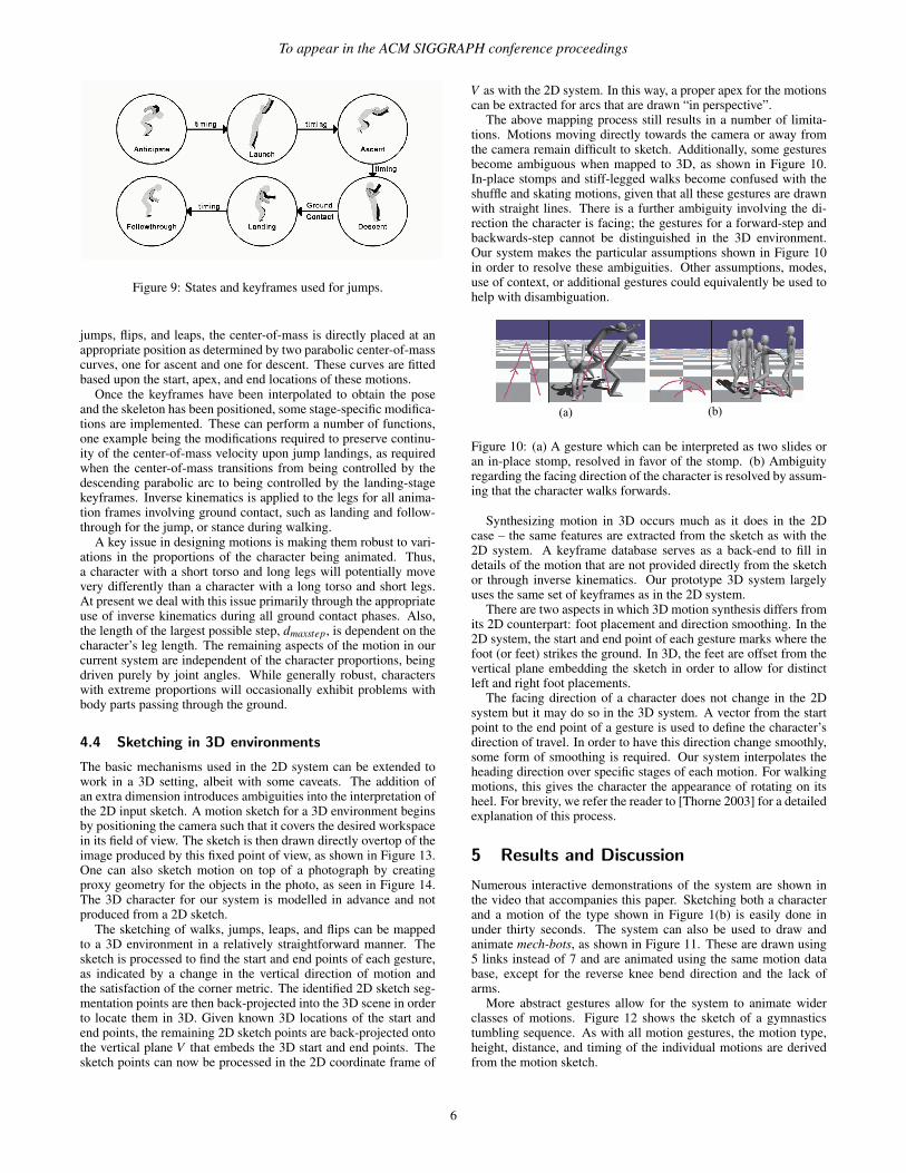
Each type of motion is implemented by breaking it into a fixednumber of stages and then applying a number of tools: a keyframedatabase, a keyframe interpolator, an inverse-kinematics solver, anda means to position the center-of-mass at a specified point. As anexample, the stages used to implement jumps are shown in Figure 9.A detailed description of the stages used for all motions may befound in [Thorne 2003].
The duration of each stage is determined as a fixed fraction of theinput-sketch times associated with the motion. For example, a jumpmotion has both ascent and descent times, which are determined di-rectly from the input sketch. The first three stages of a jump motionall determine their duration as a fixed fraction of the input-sketchascent time. The durations of the remaining three stages correspondto fixed fractions of the input-sketch descent time.
All stages of any particular motion have an associated keyframethat defines target joint angles to be reached by the character atthe end of the stage. A Catmull-Rom interpolant is used betweensuccessive keyframes. The global position of the character is con-trolled separately from the keyframes. For steps, the root of thecharacter (located at the hip) is placed halfway between the knownpositions of the stance and swing feet. For the airborne phases of
5
To appear in the ACM SIGGRAPH conference proceedings
Figure 9: States and keyframes used for jumps.
jumps, flips, and leaps, the center-of-mass is directly placed at anappropriate position as determined by two parabolic center-of-masscurves, one for ascent and one for descent. These curves are fittedbased upon the start, apex, and end locations of these motions.
Once the keyframes have been interpolated to obtain the poseand the skeleton has been positioned, some stage-specific modifica-tions are implemented. These can perform a number of functions,one example being the modifications required to preserve continu-ity of the center-of-mass velocity upon jump landings, as requiredwhen the center-of-mass transitions from being controlled by thedescending parabolic arc to being controlled by the landing-stagekeyframes. Inverse kinematics is applied to the legs for all anima-tion frames involving ground contact, such as landing and follow-through for the jump, or stance during walking.
A key issue in designing motions is making them robust to vari-ations in the proportions of the character being animated. Thus,a character with a short torso and long legs will potentially movevery differently than a character with a long torso and short legs.At present we deal with this issue primarily through the appropriateuse of inverse kinematics during all ground contact phases. Also,the length of the largest possible step, dmaxstep, is dependent on thecharacter’s leg length. The remaining aspects of the motion in ourcurrent system are independent of the character proportions, beingdriven purely by joint angles. While generally robust, characterswith extreme proportions will occasionally exhibit problems withbody parts passing through the ground.
4.4 Sketching in 3D environments
The basic mechanisms used in the 2D system can be extended towork in a 3D setting, albeit with some caveats. The addition ofan extra dimension introduces ambiguities into the interpretation ofthe 2D input sketch. A motion sketch for a 3D environment beginsby positioning the camera such that it covers the desired workspacein its field of view. The sketch is then drawn directly overtop of theimage produced by this fixed point of view, as shown in Figure 13.One can also sketch motion on top of a photograph by creatingproxy geometry for the objects in the photo, as seen in Figure 14.The 3D character for our system is modelled in advance and notproduced from a 2D sketch.
The sketching of walks, jumps, leaps, and flips can be mappedto a 3D environment in a relatively straightforward manner. Thesketch is processed to find the start and end points of each gesture,as indicated by a change in the vertical direction of motion andthe satisfaction of the corner metric. The identified 2D sketch seg-mentation points are then back-projected into the 3D scene in orderto locate them in 3D. Given known 3D locations of the start andend points, the remaining 2D sketch points are back-projected ontothe vertical plane V that embeds the 3D start and end points. Thesketch points can now be processed in the 2D coordinate frame of
V as with the 2D system. In this way, a proper apex for the motionscan be extracted for arcs that are drawn “in perspective”.
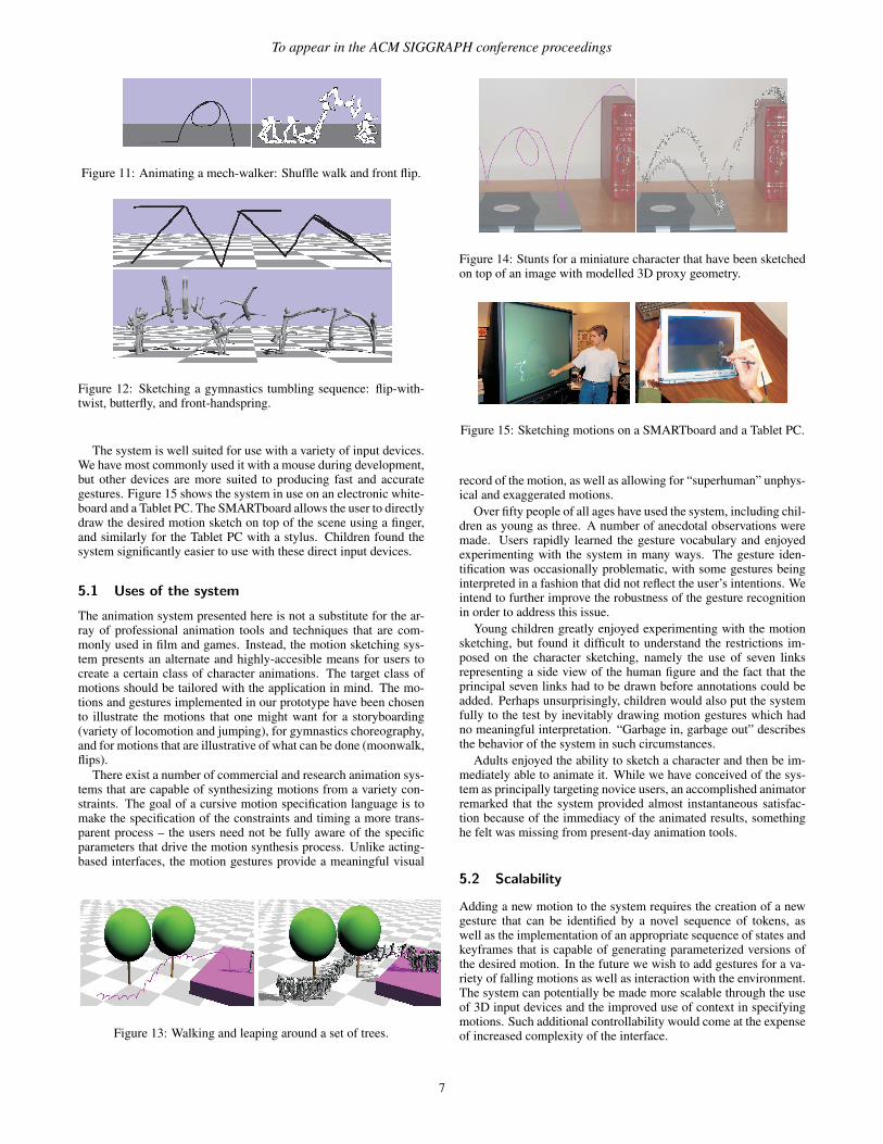
The above mapping process still results in a number of limita-tions. Motions moving directly towards the camera or away fromthe camera remain difficult to sketch. Additionally, some gesturesbecome ambiguous when mapped to 3D, as shown in Figure 10.In-place stomps and stiff-legged walks become confused with theshuffle and skating motions, given that all these gestures are drawnwith straight lines. There is a further ambiguity involving the di-rection the character is facing; the gestures for a forward-step andbackwards-step cannot be distinguished in the 3D environment.Our system makes the particular assumptions shown in Figure 10in order to resolve these ambiguities. Other assumptions, modes,use of context, or additional gestures could equivalently be used tohelp with disambiguation.
Figure 10: (a) A gesture which can be interpreted as two slides oran in-place stomp, resolved in favor of the stomp. (b) Ambiguityregarding the facing direction of the character is resolved by assum-ing that the character walks forwards.
Synthesizing motion in 3D occurs much as it does in the 2Dcase – the same features are extracted from the sketch as with the2D system. A keyframe database serves as a back-end to fill indetails of the motion that are not provided directly from the sketchor through inverse kinematics. Our prototype 3D system largelyuses the same set of keyframes as in the 2D system.
There are two aspects in which 3D motion synthesis differs fromits 2D counterpart: foot placement and direction smoothing. In the2D system, the start and end point of each gesture marks where thefoot (or feet) strikes the ground. In 3D, the feet are offset from thevertical plane embedding the sketch in order to allow for distinctleft and right foot placements.
The facing direction of a character does not change in the 2Dsystem but it may do so in the 3D system. A vector from the startpoint to the end point of a gesture is used to define the character’sdirection of travel. In order to have this direction change smoothly,some form of smoothing is required. Our system interpolates theheading direction over specific stages of each motion. For walkingmotions, this gives the character the appearance of rotating on itsheel. For brevity, we refer the reader to [Thorne 2003] for a detailedexplanation of this process.
5 Results and Discussion
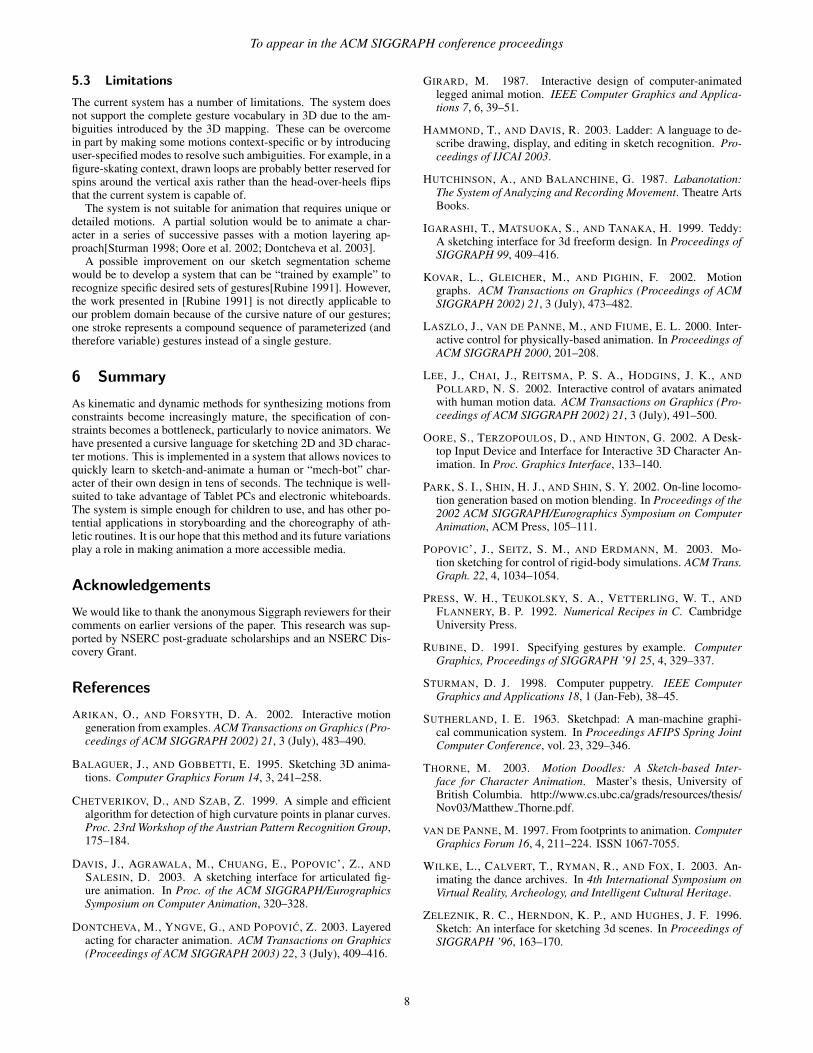
Numerous interactive demonstrations of the system are shown inthe video that accompanies this paper. Sketching both a characterand a motion of the type shown in Figure 1(b) is easily done inunder thirty seconds. The system can also be used to draw andanimate mech-bots, as shown in Figure 11. These are drawn using5 links instead of 7 and are animated using the same motion database, except for the reverse knee bend direction and the lack ofarms.
More abstract gestures allow for the system to animate widerclasses of motions. Figure 12 shows the sketch of a gymnasticstumbling sequence. As with all motion gestures, the motion type,height, distance, and timing of the individual motions are derivedfrom the motion sketch.
6
To appear in the ACM SIGGRAPH conference proceedings
Figure 11: Animating a mech-walker: Shuffle walk and front flip.
Figure 12: Sketching a gymnastics tumbling sequence: flip-with-twist, butterfly, and front-handspring.
The system is well suited for use with a variety of input devices.We have most commonly used it with a mouse during development,but other devices are more suited to producing fast and accurategestures. Figure 15 shows the system in use on an electronic white-board and a Tablet PC. The SMARTboard allows the user to directlydraw the desired motion sketch on top of the scene using a finger,and similarly for the Tablet PC with a stylus. Children found thesystem significantly easier to use with these direct input devices.
5.1 Uses of the system
The animation system presented here is not a substitute for the ar-ray of professional animation tools and techniques that are com-monly used in film and games. Instead, the motion sketching sys-tem presents an alternate and highly-accesible means for users tocreate a certain class of character animations. The target class ofmotions should be tailored with the application in mind. The mo-tions and gestures implemented in our prototype have been chosento illustrate the motions that one might want for a storyboarding(variety of locomotion and jumping), for gymnastics choreography,and for motions that are illustrative of what can be done (moonwalk,flips).
There exist a number of commercial and research animation sys-tems that are capable of synthesizing motions from a variety con-straints. The goal of a cursive motion specification language is tomake the specification of the constraints and timing a more trans-parent process – the users need not be fully aware of the specificparameters that drive the motion synthesis process. Unlike acting-based interfaces, the motion gestures provide a meaningful visual
Figure 13: Walking and leaping around a set of trees.
Figure 14: Stunts for a miniature character that have been sketchedon top of an image with modelled 3D proxy geometry.
Figure 15: Sketching motions on a SMARTboard and a Tablet PC.
record of the motion, as well as allowing for “superhuman” unphys-ical and exaggerated motions.
Over fifty people of all ages have used the system, including chil-dren as young as three. A number of anecdotal observations weremade. Users rapidly learned the gesture vocabulary and enjoyedexperimenting with the system in many ways. The gesture iden-tification was occasionally problematic, with some gestures beinginterpreted in a fashion that did not reflect the user’s intentions. Weintend to further improve the robustness of the gesture recognitionin order to address this issue.
Young children greatly enjoyed experimenting with the motionsketching, but found it difficult to understand the restrictions im-posed on the character sketching, namely the use of seven linksrepresenting a side view of the human figure and the fact that theprincipal seven links had to be drawn before annotations could beadded. Perhaps unsurprisingly, children would also put the systemfully to the test by inevitably drawing motion gestures which hadno meaningful interpretation. “Garbage in, garbage out” describesthe behavior of the system in such circumstances.
Adults enjoyed the ability to sketch a character and then be im-mediately able to animate it. While we have conceived of the sys-tem as principally targeting novice users, an accomplished animatorremarked that the system provided almost instantaneous satisfac-tion because of the immediacy of the animated results, somethinghe felt was missing from present-day animation tools.
5.2 Scalability
Adding a new motion to the system requires the creation of a newgesture that can be identified by a novel sequence of tokens, aswell as the implementation of an appropriate sequence of states andkeyframes that is capable of generating parameterized versions ofthe desired motion. In the future we wish to add gestures for a va-riety of falling motions as well as interaction with the environment.The system can potentially be made more scalable through the useof 3D input devices and the improved use of context in specifyingmotions. Such additional controllability would come at the expenseof increased complexity of the interface.
7
To appear in the ACM SIGGRAPH conference proceedings
5.3 Limitations
The current system has a number of limitations. The system doesnot support the complete gesture vocabulary in 3D due to the am-biguities introduced by the 3D mapping. These can be overcomein part by making some motions context-specific or by introducinguser-specified modes to resolve such ambiguities. For example, in afigure-skating context, drawn loops are probably better reserved forspins around the vertical axis rather than the head-over-heels flipsthat the current system is capable of.
The system is not suitable for animation that requires unique ordetailed motions. A partial solution would be to animate a char-acter in a series of successive passes with a motion layering ap-proach[Sturman 1998; Oore et al. 2002; Dontcheva et al. 2003].
A possible improvement on our sketch segmentation schemewould be to develop a system that can be “trained by example” torecognize specific desired sets of gestures[Rubine 1991]. However,the work presented in [Rubine 1991] is not directly applicable toour problem domain because of the cursive nature of our gestures;one stroke represents a compound sequence of parameterized (andtherefore variable) gestures instead of a single gesture.
6 Summary
As kinematic and dynamic methods for synthesizing motions fromconstraints become increasingly mature, the specification of con-straints becomes a bottleneck, particularly to novice animators. Wehave presented a cursive language for sketching 2D and 3D charac-ter motions. This is implemented in a system that allows novices toquickly learn to sketch-and-animate a human or “mech-bot” char-acter of their own design in tens of seconds. The technique is well-suited to take advantage of Tablet PCs and electronic whiteboards.The system is simple enough for children to use, and has other po-tential applications in storyboarding and the choreography of ath-letic routines. It is our hope that this method and its future variationsplay a role in making animation a more accessible media.
Acknowledgements
We would like to thank the anonymous Siggraph reviewers for theircomments on earlier versions of the paper. This research was sup-ported by NSERC post-graduate scholarships and an NSERC Dis-covery Grant.
References
ARIKAN, O., AND FORSYTH, D. A. 2002. Interactive motiongeneration from examples. ACM Transactions on Graphics (Pro-ceedings of ACM SIGGRAPH 2002) 21, 3 (July), 483–490.
BALAGUER, J., AND GOBBETTI, E. 1995. Sketching 3D anima-tions. Computer Graphics Forum 14, 3, 241–258.
CHETVERIKOV, D., AND SZAB, Z. 1999. A simple and efficientalgorithm for detection of high curvature points in planar curves.Proc. 23rd Workshop of the Austrian Pattern Recognition Group,175–184.
DAVIS, J., AGRAWALA, M., CHUANG, E., POPOVIC’, Z., ANDSALESIN, D. 2003. A sketching interface for articulated fig-ure animation. In Proc. of the ACM SIGGRAPH/EurographicsSymposium on Computer Animation, 320–328.
DONTCHEVA, M., YNGVE, G., AND POPOVIC, Z. 2003. Layeredacting for character animation. ACM Transactions on Graphics(Proceedings of ACM SIGGRAPH 2003) 22, 3 (July), 409–416.
GIRARD, M. 1987. Interactive design of computer-animatedlegged animal motion. IEEE Computer Graphics and Applica-tions 7, 6, 39–51.
HAMMOND, T., AND DAVIS, R. 2003. Ladder: A language to de-scribe drawing, display, and editing in sketch recognition. Pro-ceedings of IJCAI 2003.
HUTCHINSON, A., AND BALANCHINE, G. 1987. Labanotation:The System of Analyzing and Recording Movement. Theatre ArtsBooks.
IGARASHI, T., MATSUOKA, S., AND TANAKA, H. 1999. Teddy:A sketching interface for 3d freeform design. In Proceedings ofSIGGRAPH 99, 409–416.
KOVAR, L., GLEICHER, M., AND PIGHIN, F. 2002. Motiongraphs. ACM Transactions on Graphics (Proceedings of ACMSIGGRAPH 2002) 21, 3 (July), 473–482.
LASZLO, J., VAN DE PANNE, M., AND FIUME, E. L. 2000. Inter-active control for physically-based animation. In Proceedings ofACM SIGGRAPH 2000, 201–208.
LEE, J., CHAI, J., REITSMA, P. S. A., HODGINS, J. K., ANDPOLLARD, N. S. 2002. Interactive control of avatars animatedwith human motion data. ACM Transactions on Graphics (Pro-ceedings of ACM SIGGRAPH 2002) 21, 3 (July), 491–500.
OORE, S., TERZOPOULOS, D., AND HINTON, G. 2002. A Desk-top Input Device and Interface for Interactive 3D Character An-imation. In Proc. Graphics Interface, 133–140.
PARK, S. I., SHIN, H. J., AND SHIN, S. Y. 2002. On-line locomo-tion generation based on motion blending. In Proceedings of the2002 ACM SIGGRAPH/Eurographics Symposium on ComputerAnimation, ACM Press, 105–111.
POPOVIC’, J., SEITZ, S. M., AND ERDMANN, M. 2003. Mo-tion sketching for control of rigid-body simulations. ACM Trans.Graph. 22, 4, 1034–1054.
PRESS, W. H., TEUKOLSKY, S. A., VETTERLING, W. T., ANDFLANNERY, B. P. 1992. Numerical Recipes in C. CambridgeUniversity Press.
RUBINE, D. 1991. Specifying gestures by example. ComputerGraphics, Proceedings of SIGGRAPH ’91 25, 4, 329–337.
STURMAN, D. J. 1998. Computer puppetry. IEEE ComputerGraphics and Applications 18, 1 (Jan-Feb), 38–45.
SUTHERLAND, I. E. 1963. Sketchpad: A man-machine graphi-cal communication system. In Proceedings AFIPS Spring JointComputer Conference, vol. 23, 329–346.
THORNE, M. 2003. Motion Doodles: A Sketch-based Inter-face for Character Animation. Master’s thesis, University ofBritish Columbia. http://www.cs.ubc.ca/grads/resources/thesis/Nov03/Matthew Thorne.pdf.
VAN DE PANNE, M. 1997. From footprints to animation. ComputerGraphics Forum 16, 4, 211–224. ISSN 1067-7055.
WILKE, L., CALVERT, T., RYMAN, R., AND FOX, I. 2003. An-imating the dance archives. In 4th International Symposium onVirtual Reality, Archeology, and Intelligent Cultural Heritage.
ZELEZNIK, R. C., HERNDON, K. P., AND HUGHES, J. F. 1996.Sketch: An interface for sketching 3d scenes. In Proceedings ofSIGGRAPH ’96, 163–170.
8