door control embedded system using accelerometer sensor
TRANSCRIPT
CE00626-2 DES-2 Individual Assignment P a g e | 1
Level-2 Asia Pacific Institute of Information Technology April-2016
Table of Contents Acknowledgement……………………………………………………………………………….. (i)
Introduction ....................................................................................................................................... 2
Working Principle and detailed theory ............................................................................................. 3
List & Description of the components .......................................................................................... 4
ADC 0804: ................................................................................................................................ 4
AT89S51-Microcontroller ........................................................................................................ 4
DC Jack: .................................................................................................................................... 6
7805 voltage regulator .............................................................................................................. 7
Resistor: .................................................................................................................................... 7
Capacitor ................................................................................................................................... 8
Preset: ........................................................................................................................................ 8
Crystal Oscillator ...................................................................................................................... 9
Accelerometer (Tilt Sensor) ...................................................................................................... 9
555 Timer ................................................................................................................................ 11
Reset Switch............................................................................................................................ 11
LCD (Liquid Crystal Display 16X2) ...................................................................................... 12
Electrical Connector................................................................................................................ 12
Circuit Design and testing:.............................................................................................................. 13
Circuit Analysis: ............................................................................................................................. 21
Result: ............................................................................................................................................. 22
Conclusion: ..................................................................................................................................... 23
References ....................................................................................................................................... 24
Appendix…………….....................................................................................................................26

CE00626-2 DES-2 Individual Assignment P a g e | 2
Level-2 Asia Pacific Institute of Information Technology April-2016
Introduction Digital Embedded Software module deals with the introductory state of the vast field
embedded systems which includes the combination and working of microcontroller, embedded C
languages, sensors, different devices and electronic or mechanical tools with their dedicated
capabilities, to develop a product having a capabilities of performing desired dedicated task.
This assignment has an objective to design and develop an automatic door locking
embedded system circuit with a 68hc11/8051 microcontroller and accelerometer or also known as
tilt Sensor which will have capabilities to lock and unlock the door with movement of a connected
device which is kept away from the door or window with which the system is dedicated.
Accelerometer used in the circuit is a major device which detects the tilts motions to
determine the direction of the tilts done by the user and for the inclinations or tilt sensing a tilt
sensor is fixed which is sensitive to the motions of device. Some of other specifications includes
that, as there would be fixed constraints of the angle of motion and direction with which the door
should be unlocked but if these attempts of tilting the sensors goes wrong more than two times, the
whole system would be blocked for next two hours and user will be unable to access the system for
this time interval. Different other components for the design includes Resistors, Capacitors, sensors,
ADC and LCD. ADC (Analog to Digital Converter) used to convert the analog electrical signal
produced by the tilting of the tilt sensor into Digital ones so that it can be easy to predict the values
at which door automation should work. LCD (Liquid Crystal Display) is used to show the status of
the system at the time of operation, such as, if wrong attempts have been made by the user then it
should show ‘Wrong attempt’. I will be using multimeter to check the voltage and current at
different points of the circuit.
Now, proceeding on the working of design, after starting of the system the tilt sensor should
be activated for sensing the motion of the transmitter device which includes an accelerometer to
determine the direction of the tilts made. If the inclination attempted is wrong more than two times
simultaneously then there should be blocking of the whole system for next two hours thereby
ceasing the any of the users operation but if the tilt is as per the desired accuracy then the electric
analog signal produced by this motion is sent to an ADC which converts these analog signal into
Digital ones which gives a proper reading to microcontroller to work as per users desire. Now,
microcontroller senses the matched motion and confirms it for its absoluteness. After that it

CE00626-2 DES-2 Individual Assignment P a g e | 3
Level-2 Asia Pacific Institute of Information Technology April-2016
commands the devices fixed on the door to be unlocked or locked as per its corresponding digital
values of their respective motions. Also, Locking and unlocking of the door should be indicated on
the LCD.
Embedded C Language is used in this assignment for programming the microcontroller with
desired values digital signals of motion and also for defining the working of the different devices
at particular constraints of the given conditions which include the LCD working and indication
command line, defining the condition of the door system at which it should be locked, unlocked, or
blocked for hours if the users has made more than two wrong attempts.
Working Principle and detailed theory This project explained above is working using a microcontroller which has an inbuilt CPU
that’s why it’s working principle includes the IPO cycle that means this Project (Hardware circuit)
has component to take Input then interpret that data and from the last i.e. the output device will
show the output. The Block diagram shown below will give a visual representation of the working
principle of the project.
Figure 1: Block Diagram

CE00626-2 DES-2 Individual Assignment P a g e | 4
Level-2 Asia Pacific Institute of Information Technology April-2016
List & Description of the components
ADC 0804: ADC -0804 devices are CMOS 8-bit successive approximation converters
(ADC) that use a differential potentiometric ladder These converters are designed to allow operation
with the NSC800 and INS8080A derivative control bus with Tri state output latches directly driving
the data bus It appears like memory location or I/O ports to the microprocessor and no interfacing
logic is needed.
Features:
Compatible with 8080 microcontroller
Access time 135 ns
Differential analog voltage inputs
Logic inputs and outputs meet both MOS and TTL voltage level specification
Works with 2.5-v
0-v to 50v analog input voltage range with single 5-v supply
No zero adjust required
20-pin molded chip carrier or small outline package
Resolution 8 Bits
Conversion Time: 100 µ
AT89S51-Microcontroller: The AT89S51 is a low-power, high-performance CMOS 8-bit
microcontroller with 4K bytes of In-System Programmable Flash memory. The device is
manufactured using Atmel’s high-density nonvolatile memory technology and is compatible with
the industry-standard 80C51 instruction set and pin out. The on-chip Flash allows the program
Figure 2: ADC-0804

CE00626-2 DES-2 Individual Assignment P a g e | 5
Level-2 Asia Pacific Institute of Information Technology April-2016
memory to be reprogrammed in-system or by a conventional nonvolatile memory programmer. By
combining a versatile 8-bit CPU with In-System Programmable Flash on a monolithic chip, the
Atmel AT89S51 is a powerful microcontroller which provides a highly-flexible and cost-effective
solution to many embedded control applications.
The AT89S51 provides the following standard features: 4K bytes of Flash, 128 bytes of
RAM, 32 I/O lines, Watchdog timer, two data pointers, two 16-bit timer/counters, a five-vector
two-level interrupt architecture, a full duplex serial port, on-chip oscillator, and clock circuitry. In
addition, the AT89S51 is designed with static logic for operation down to zero frequency and
supports two software selectable power saving modes. The Idle Mode stops the CPU while allowing
the RAM, timer/counters, serial port, and interrupt system to continue functioning. The Power-
down mode saves the RAM contents but freezes the oscillator, disabling all other chip functions
until the next external interrupt or hardware reset.
Features
Compatible with MCS®-51 Products
4 K Bytes of In-System Programmable (ISP) Flash Memory – Endurance: 10,000
Write/Erase Cycles
4.0 V to 5.5V Operating Range
Fully Static Operation: 0 Hz to 33 MHz
Three-level Program Memory Lock
128 x 8-bit Internal RAM
32 Programmable I/O Lines
Two 16-bit Timer/Counters
Six Interrupt Sources
Full Duplex UART Serial Channel
Low-power Idle and Power-down Modes
Interrupt Recovery from Power-down Mode
Watchdog Timer
Dual Data Pointer
Power-off Flag
Fast Programming Time

CE00626-2 DES-2 Individual Assignment P a g e | 6
Level-2 Asia Pacific Institute of Information Technology April-2016
Flexible ISP Programming (Byte and Page Mode)
Green (Pb/Halide-free) Packaging Option
DC Jack: A DC connector (or DC plug, for one common type of connector) is an electrical
connector for supplying direct current (DC) power. Compared to domestic AC power plugs and
sockets, DC connectors have many more standard types that are not interchangeable. The
dimensions and arrangement of DC connectors can be chosen to prevent accidental interconnection
of incompatible sources and loads. Types vary from small coaxial connectors used to power
portable electronic devices from AC adapters, to connectors used for automotive accessories and
for battery packs in portable equipment.
Figure 3: AT89S51MicroController
Figure 4: DC Jack

CE00626-2 DES-2 Individual Assignment P a g e | 7
Level-2 Asia Pacific Institute of Information Technology April-2016
7805 voltage regulator: 7805 is a voltage regulator integrated circuit. It is a member of
78xx series of fixed linear voltage regulator ICs. The voltage source in a circuit may have
fluctuations and would not give the fixed voltage output. The voltage regulator IC maintains the
output voltage at a constant value. The xx in 78xx indicates the fixed output voltage it is designed
to provide. 7805 provides +5V regulated power supply. Capacitors of suitable values can be
connected at input and output pins depending upon the respective voltage levels.
Resistor: A resistor is a passive two-terminal electrical component that
implements electrical resistance as a circuit element.
Figure 5: IC 7805
Figure 6: Resistor

CE00626-2 DES-2 Individual Assignment P a g e | 8
Level-2 Asia Pacific Institute of Information Technology April-2016
Capacitor: A capacitor (originally known as a condenser) is a passive two-
terminal electrical component used to store electrical energy temporarily in an electric field.
Figure 7: Capacitors
Preset: A preset is a three legged electronic component which can be made to offer varying
resistance in a circuit. The resistance is varied by adjusting the rotary control over it. The adjustment
can be done by using a small screw driver or a similar tool. The resistance does not vary linearly
but rather varies in exponential or logarithmic manner. Such variable resistors are commonly used
for adjusting sensitivity along with a sensor.
Figure 8: Preset (Variable Resistor)
CE00626-2 DES-2 Individual Assignment P a g e | 9
Level-2 Asia Pacific Institute of Information Technology April-2016
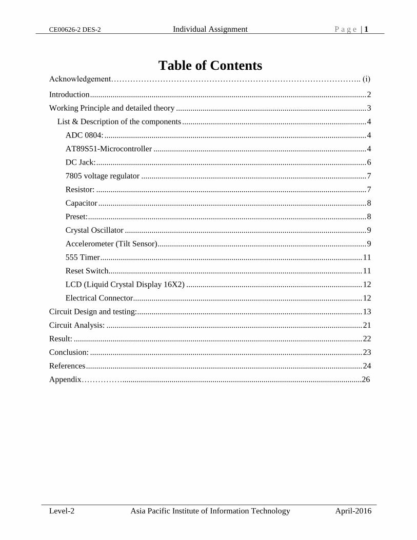
Crystal Oscillator: A crystal oscillator is an electronic oscillator circuit that uses the
mechanical resonance of a vibrating crystal of piezoelectric material to create an electrical signal
with a precise frequency. This frequency is commonly used to keep track of time, as in quartz
wristwatches, to provide a stable clock signal for digital integrated circuits, & to stabilize
frequencies for radio transmitters and receivers. The most common type of piezoelectric resonator
used is the quartz crystal, so oscillator circuits incorporating them became known as crystal
oscillators.
Accelerometer (Tilt Sensor): An accelerometer is a device that measures proper
acceleration (g-force). Proper acceleration is not the same as coordinate acceleration. For example,
an accelerometer at rest on the surface of the Earth will measure an acceleration of
g= 9.81 m/s2 straight upwards. By contrast, accelerometers in free fall (falling toward the center of
the Earth at a rate of about 9.81 m/s2) will measure zero. This is also called as a tilt sensor as it
detects the tilt of itself on the axis it is defined with (X, Y, Z).
Single- and multi-axis models of accelerometer are available to detect magnitude and
direction of the proper acceleration (or g-force), as a vector quantity, and can be used to sense
orientation (because direction of weight changes), coordinate acceleration (so long as it produces
g-force or a change in g-force), vibration, shock, and falling in a resistive medium (a case where
the proper acceleration changes, since it starts at zero, then increases).
Figure 9: Crystal Oscillator

CE00626-2 DES-2 Individual Assignment P a g e | 10
Level-2 Asia Pacific Institute of Information Technology April-2016
Features:
Ultralow power: as low as 23 µA in measurement mode and 0.1 µA in standby
mode at Vs=2.5 V (typical) Power consumption scales automatically with
bandwidth
User-selectable resolution Fixed 10-bit resolution Full resolution, where resolution
increases with g range, up to 13-bit resolution at ±16 g (maintaining 4 mg/LSB scale
factor in all g ranges)
Embedded memory management system with FIFO technology minimizes host
processor load Single tap/double tap detection Activity/inactivity monitoring Free-
fall detection
Supply voltage range: 2.0 V to 3.6 V
I/O voltage range: 1.7 V to Vs
SPI (3- and 4-wire) and I2C digital interfaces
Flexible interrupt modes map able to either interrupt pin
Measurement ranges selectable via serial command
Bandwidth selectable via serial command
Wide temperature range (−40°C to +85°C)
10,000 g shock survival
Pb free/RoHS compliant
Small and thin: 3 mm × 5 mm × 1 mm LGA package
Figure 10: Accelerometer (Tilt Sensor)

CE00626-2 DES-2 Individual Assignment P a g e | 11
Level-2 Asia Pacific Institute of Information Technology April-2016
555 Timer: The 555 timer IC is an integrated circuit (chip) used in a variety of timer, pulse
generation, and oscillator applications. The 555 can be used to provide time delays, as an oscillator,
and as a flip-flop element. Derivatives provide up to four timing circuits in one package.
Reset Switch: The Reset Switch provide a useful feature which ensures that inadvertent
short reset push-button closures do not cause system resets. This is done by implementing an
extended Smart Reset input delay time which ensures a safe reset of the programme inside the
microcontroller.
Figure 11: 555 Timer
Figure 12: Reset Switch

CE00626-2 DES-2 Individual Assignment P a g e | 12
Level-2 Asia Pacific Institute of Information Technology April-2016
LCD (Liquid Crystal Display 16X2): LCD (Liquid Crystal Display) screen is an electronic
display module and find a wide range of applications. A 16x2 LCD display is very basic module
and is very commonly used in various devices and circuits. These modules are preferred over seven
segments and other multi segment LEDs. The reasons being, LCDs are economical, easily
programmable, have no limitation of displaying special & even custom characters (unlike in seven
segments), animations and so on. A 16x2 LCD means it can display 16 characters per line and there
are 2 such lines. In this LCD each character is displayed in 5x7 pixel matrix. This LCD has two
registers which are Command and Data.
The command register stores the command instructions given to the LCD. A command is
an instruction given to LCD to do a predefined task like initializing it, clearing its screen, setting
the cursor position, controlling display etc. The data register stores the data to be displayed on the
LCD. The data is the ASCII value of the character to be displayed on the LCD.
Electrical Connector: Electrical connector, a device for joining electrical circuits together
which are ports, Plugs, Jumper wires & Pins.
Figure 13: Liquid Crystal Display
Figure 15: Male Header Figure 16: Female Header Figure 14: Jumper wires

CE00626-2 DES-2 Individual Assignment P a g e | 13
Level-2 Asia Pacific Institute of Information Technology April-2016
After Mounting these all components altogether on a designed which is made by itching process
with proper connection and a proper code need to be embedded in the microcontroller then the
project will be working to open and close a door by tilting the sensor by a far distance(inside the
room) with wired or wireless connection.
Circuit Design and testing:
Following are the screen shots showing the schematic working and non-working design of
the circuit which I made using Proteus Simulating software.
1. Schematic Circuit Diagram showing all the mounted components (Not running as real
time circuit). Here I am using two different variable resistors to give input of tilt
sensor since real tilt sensor is not available in Proteus component Library. In these two
one variable resistor is providing VReference and the second one is providing Vin . For
testing the circuit on simulating software I am changing the value of resistance of the
second variable resistor
Figure 17: Ideal Schematic Proteus Circuit Diagram
CE00626-2 DES-2 Individual Assignment P a g e | 14
Level-2 Asia Pacific Institute of Information Technology April-2016
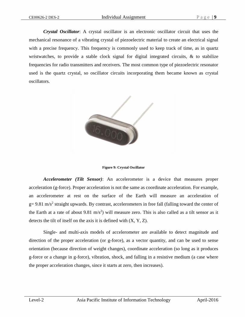
2. Real Time schematic circuit diagram showing 96, reading of the variable resistor and
“Open” and the range under which it will show open is 50-100 for this the program is
already been embedded in the controller used.
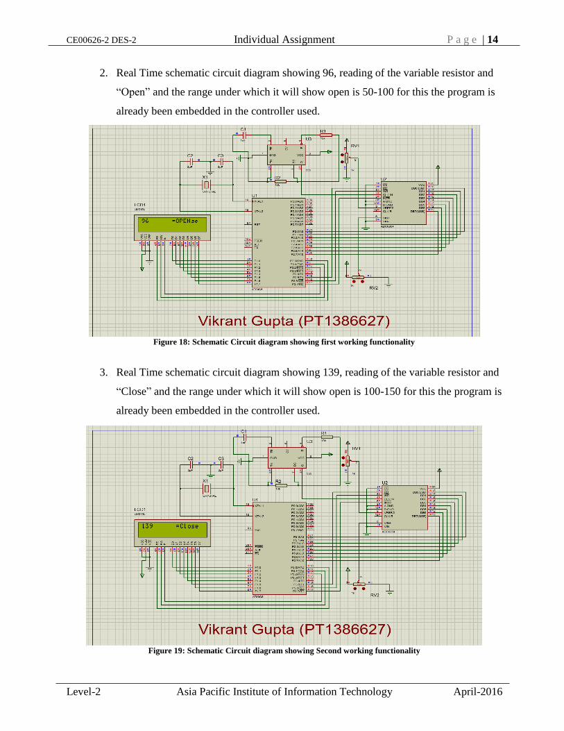
3. Real Time schematic circuit diagram showing 139, reading of the variable resistor and
“Close” and the range under which it will show open is 100-150 for this the program is
already been embedded in the controller used.
Figure 18: Schematic Circuit diagram showing first working functionality
Figure 19: Schematic Circuit diagram showing Second working functionality

CE00626-2 DES-2 Individual Assignment P a g e | 15
Level-2 Asia Pacific Institute of Information Technology April-2016
4. Real Time schematic circuit diagram showing 190, reading of the variable resistor and
“Error” and the range under which it will show open is 150-α for this the program is
already been embedded in the controller used
5. Real Time schematic circuit diagram showing 173, reading of the variable resistor and
“Error” and it comes when more than two error attempts takes place.
Figure 20: Schematic Circuit diagram showing third working functionality
Figure 21: Schematic Circuit diagram showing fourth working functionality

CE00626-2 DES-2 Individual Assignment P a g e | 16
Level-2 Asia Pacific Institute of Information Technology April-2016
6. PCB layout design designed using Eagle 6.5.0 software.
Figure 23: PCB Design (Tracks & holes)
Figure 22: PCB Design (Tracks, Holes & Components)

CE00626-2 DES-2 Individual Assignment P a g e | 17
Level-2 Asia Pacific Institute of Information Technology April-2016
7. Hardware Project
Bottom View
Top View
Figure 24: Hardware Project (Bottom View)
Figure 25: Hardware Project (Top View)

CE00626-2 DES-2 Individual Assignment P a g e | 18
Level-2 Asia Pacific Institute of Information Technology April-2016
8. Code embedded in the controller
#include<reg51.h>
#include<delay.h>
#include<lcd.h>
sbit R=P3^5;
sbit WD=P3^6;
sbit INT=P3^7;
int read_ADC()
{
int temp;
R=1;
WD=0;
WD=1;
while(INT==1);
R=1;
R=0;
temp=P2;
return temp;
}
void main()
{
unsigned char value='#';
INT=1;
P2=0xff;
Lcd8_Init();
while(1)
{
value=read_ADC();
Lcd8_Cmd(0x80);
Lcd8_Num(value);
if(value<100&&value>50)
{
Lcd8_Write_String(" = OPEN");
delay_msec(100);
}
else if(value>=100&&value<150)
{

CE00626-2 DES-2 Individual Assignment P a g e | 19
Level-2 Asia Pacific Institute of Information Technology April-2016
Lcd8_Write_String(" =Close");
delay_msec(100);
}
else
{
Lcd8_Write_String(" =Error");
delay_msec(100);
if(value<100&&value>50)
{
Lcd8_Write_String(" = OPEN");
delay_msec(100);
}
else if(value>=100&&value<150)
{
Lcd8_Write_String(" =Close");
delay_msec(100);
}
else
{
Lcd8_Write_String(" =Error");
delay_msec(100);
if(value<100&&value>50)
{
Lcd8_Write_String(" = OPEN");
delay_msec(100);
}
else if(value>=100&&value<150)
{
Lcd8_Write_String(" =Close");
delay_msec(100);
}
else
{

CE00626-2 DES-2 Individual Assignment P a g e | 20
Level-2 Asia Pacific Institute of Information Technology April-2016
Lcd8_Write_String(" =locked");
delay_msec(640000);
}
}
}
}
}
9. Testing
Figure 27: Working Hardware (Functionality-3)
Figure 26: Working Hardware (Functionality-2)

CE00626-2 DES-2 Individual Assignment P a g e | 21
Level-2 Asia Pacific Institute of Information Technology April-2016
Circuit Analysis:
Voltage
Circuit Case
(Output on LCD)
Input Voltage
(Across the sensor)
Output Voltage
(Across the LCD)
Open +1.05 V +/- 5 V
Closed +0.05 V +/- 5 V
Error -1.15 V +/- 5 V
Locked -1.95 V +/- 5 V
Table 1: Voltage Observed
Current
Circuit Case
(Output on LCD)
Input Current
(Across the sensor)
Output Current
(Across the LCD)
Open
Closed
Error
Locked
Table 2: Current Observed
Figure 28: Working Hardware (Functionality-1)
CE00626-2 DES-2 Individual Assignment P a g e | 22
Level-2 Asia Pacific Institute of Information Technology April-2016
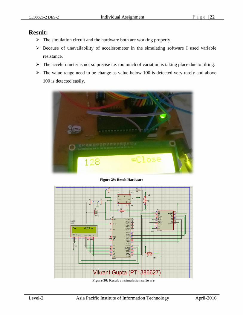
Result: The simulation circuit and the hardware both are working properly.
Because of unavailability of accelerometer in the simulating software I used variable
resistance.
The accelerometer is not so precise i.e. too much of variation is taking place due to tilting.
The value range need to be change as value below 100 is detected very rarely and above
100 is detected easily.
Figure 29: Result Hardware
Figure 30: Result on simulation software

CE00626-2 DES-2 Individual Assignment P a g e | 23
Level-2 Asia Pacific Institute of Information Technology April-2016
Conclusion: Accelerometer need to be a bit more precise
Design should be made like no component should cover another component
Locked feature should be executed at-least after five error attempts
Along with the LCD display to show the output I should have also used some device like
motorized control door locking system but as it is so expensive I could use that.
For future development feedback voice for locking, Closing, Error and lock can also be
implemented.
This entire circuit can be placed in a Rubix cube (Just a hollow shape) which will be rotated
on a table to control the window, door as well as the ventilation of the room, as we have 3
axis in the accelerometer and three different task can also be controlled using it, wirelessly
by adding RF module to same circuit.

CE00626-2 DES-2 Individual Assignment P a g e | 24
Level-2 Asia Pacific Institute of Information Technology April-2016
References
1. Anon, (2016). Technical Documents. [online] Available at:
http://www2.st.com/content/ccc/resource/technical/document/datasheet/64/0c/7a
/6e/32/e1/49/8c/DM00036192.pdf/files/DM00036192.pdf/jcr:content/translation
s/en.DM00036192.pdf [Accessed 17 Apr. 2016].
2. Autorouting PCB layout. (1979). Computer-Aided Design, 11(1), p.48.
3. Cruz, A. (2016). 7805 Voltage Regulator IC | 7805 Datasheet | Pin Diagram &
Description - EngineersGarage. [online] Engineersgarage.com. Available at:
http://www.engineersgarage.com/electronic-components/7805-voltage-
regulator-ic [Accessed 20 Apr. 2016].
4. Engineering Garage. (2016). Voltage Regulator. [online] Available at:
http://www.engineersgallery.com/wp-content/uploads/2014/09/5pcs-LM7805-
L7805-font-b-7805-b-font-Voltage-Regulator-IC-font-b-5V-b-font1.jpg'
[Accessed 20 Apr. 2016].
5. Engineersgarage.com. (2016). 16 x 2 LCD Datasheet | 16x2 Character LCD
Module PINOUT - EngineersGarage. [online] Available at:
http://www.engineersgarage.com/electronic-components/16x2-lcd-module-
datasheet [Accessed 17 Apr. 2016].
6. Engineersgarage.com. (2016). 16 x 2 LCD Datasheet | 16x2 Character LCD
Module PINOUT - EngineersGarage. [online] Available at:
http://www.engineersgarage.com/electronic-components/16x2-lcd-module-
datasheet [Accessed 21 Apr. 2016].
7. Jolly, R. (1980). A piezoelectric integrated circuit accelerometer.
8. Khan, A. (2016). Presets | Variable Resistors - EngineersGarage. [online]
Engineersgarage.com. Available at:
http://www.engineersgarage.com/electronic-components/presets-variable-
resistors [Accessed 20 Apr. 2016].
9. Kundra, D. (2016). ADXL Technical Details. [online] Engineering Garage.
Available at: http://www.analog.com/media/en/technical-documentation/data-
sheets/ADXL345.pdf [Accessed 19 Apr. 2016].

CE00626-2 DES-2 Individual Assignment P a g e | 25
Level-2 Asia Pacific Institute of Information Technology April-2016
10. Kundra, N. (2016). 89S51 Technical Information. [online] Atmel Corporation.
Available at: http://www.atmel.com/images/doc2487.pdf [Accessed 21 Apr.
2016].
11. Mazidi, M. and McKinlay, R. (2006). The 8051 microcontroller and embedded
systems. Upper Saddle River, N.J.: Pearson/Prentice Hall.
12. Mazidi, M., McKinlay, R. and Causey, D. (2008). PIC microcontroller and
embedded systems. Upper Saddle River, N.J.: Pearson Prentice Hall.
13. Neue und aktualisierte Referenzwerte für Organochlorverbindungen (PCB ,
PCB , PCB , HCB, ß-HCH und DDE) im Vollblut von Kindern in Deutschland.
(2009). Bundesgesundheitsblatt - Gesundheitsforschung - Gesundheitsschutz,
52(10), pp.973-976.
14. PCB design tools. (1985). Computer-Aided Design, 17(6), p.293.
15. Shah, N. (2016). Engineering Garage. [online]
Codefoster.blob.core.windows.net. Available at:
http://codefoster.blob.core.windows.net/site/image/4fd3e854b0f94f848b154077
4b82afa5/gochute_adxl_1.jpg [Accessed 19 Apr. 2016].
16. Techno Info. (2016). Reset Switch Technical Details. [online] Available at:
http://www2.clipsal.com/cis/__data/page/428/Track%203000%20Reset%20Swit
ch%20PDS2.pdf [Accessed 22 Apr. 2016].
17. Upload.wikimedia.org. (2016). IC Information. [online] Available at:
https://upload.wikimedia.org/wikipedia/commons/2/21/Signetics_NE555N.JPG
[Accessed 18 Apr. 2016].