door fan manual - flir infrared camera thermal … heater and gas fireplace pilot lights have not...
TRANSCRIPT

Revised 2009-02-01
Page 1 of 72
Door Fan Manual 2000 & 3000 Fans, DM-2 mark II & Analog gauges, Cloth & Modular Panels
Residential, Scientific and Industrial Applications
Applications
Revised 2008-07-05

Revised 2009-02-01
Page 2 of 72
Copyright © 2006, 2007 Retrotec Energy Innovations Ltd All rights reserved. This document contains materials protected under International Copyright Laws. All rights reserved. No part of this document may be copied or reproduced in any form or by any means without the prior written consent of Retrotec Energy Innovations Ltd. Retrotec makes no warranties with respect to this documentation and disclaims any implied warranties of merchantability, quality, or fitness for any particular purpose. The information in this document is subject to change without notice. Retrotec reserves the right to make revisions to this publication without obligation to notify any person or entity of any such changes. Infiltrometer, Energy 2001, E2001, Door Fan 3.0 and DF3 are Trademarks of Retrotec Energy Innovations Ltd. Other trademarks or brand names mentioned herein are trademarks or registered trademarks of their respective

Revised 2009-02-01
Page 3 of 72
Table of Contents 1 PREPARING THE HOUSE........................................................................ 6
1.1 Introduction.....................................................................................................................................................6 1.2 Use the House Preparation Checklist ..............................................................................................................7 1.3 Which Doorway to Use? .................................................................................................................................7 1.4 Preparation of Intentional Openings ...............................................................................................................8 1.5 Preparation of Intentional Openings ...............................................................................................................9 1.6 Other Precautions..........................................................................................................................................13
2 INSTALLING THE DOOR PANEL & FAN ........................................................15 2.1 Cloth Door Panel with Aluminum Frame - Models E43, R43, Q46 Single Fan...........................................15 2.2 Modular Hard Panel Set-Up - Model Q56 Single Fan ..................................................................................18 2.3 Modular Hard Panel Door Set-Up - Model Q56 X 2 Double Fan ................................................................23 2.4 Field Calibration Setup .................................................................................................................................24
3 SETTING UP GAUGES & SPEED CONTROLS ...................................................25 3.1 Analog Gauge Clip - Model E43 ..................................................................................................................25 3.2 Analog Gauge Readings................................................................................................................................28 3.3 Model DM-2 Digital Gauge – Models R31, R43, Q32, Q46, Q56 and Q56x2 ............................................29
4 USING FLOW RANGE CONFIGURATIONS.......................................................34 4.1 Principles of Door-fan Air Flow Measurement.............................................................................................34 4.2 Changing Fan Flow Ranges ..........................................................................................................................35 4.3 Range Selection Procedure ...........................................................................................................................37 4.4 Cannot Achieve Desired Room Pressure with Range - Open .......................................................................38 4.5 Flow Ranges and Flow Direction..................................................................................................................38 4.6 2000 and 3000 Series Fan Ranges ................................................................ Error! Bookmark not defined.
5 APPENDIX A; RETROTEC DM-2 & DM-2A – TWO CHANNEL DIGITAL GAUGE ................40 5.1 Features at a glance .......................................................................................................................................40 5.2 Keypad - [Mode]...........................................................................................................................................42 5.3 Keypad - [Range/Config]..............................................................................................................................43 5.4 Keypad - [Setup] ...........................................................................................................................................43 5.5 Keypad - [Baseline] ......................................................................................................................................45 5.6 Keypad - [Time Avg] ....................................................................................................................................45 5.7 Keypad - [Auto Zero]....................................................................................................................................45 5.8 Keypad - [Set Pressure] [Set Flow] [Set Speed] ...........................................................................................45 5.9 Keypad - [Device].........................................................................................................................................45 5.10 Keypad - [@] ................................................................................................................................................45 5.11 DM-2 Display and Buttons ...........................................................................................................................46 5.12 Configuring and Using the DM-2 for Specific Standards.............................................................................49
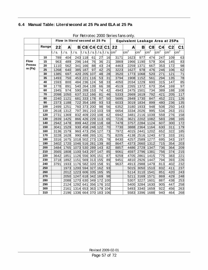
6 APPENDIX B - MANUAL AIRFLOW AND LEAKAGE AREA RESULTS..............................54 6.1 Calculating Airflow Manually ......................................................................................................................54 6.2 Manual CFM Tables .....................................................................................................................................55 6.3 Manual Table: Liters/second at 10 Pa and ELA at 10 Pa..............................................................................56 6.4 Manual Table: Liters/second at 25 Pa and ELA at 25 Pa..............................................................................57 6.5 Manual Table: CFM at 50 Pa and 25 Pa Table .............................................................................................58 6.6 Temperature Correction ................................................................................................................................59 6.7 Sample 1-Year Gauge Calibration Certificate...............................................................................................60 6.8 Temperature Correction Table for Enclosure Depressurization....................................................................61 6.9 Temperature Correction Table for Enclosure Pressurization ........................................................................62

Revised 2009-02-01
Page 4 of 72
6.10 Flow Formulae ..............................................................................................................................................63
7 APPENDIX C GLOSSARY OF DEFINITIONS......................................................66
8 APPENDIX D: TROUBLESHOOTING............................................................69 8.1 Motors Overheat and Shutoff........................................................................................................................69 8.2 Windy Conditions .........................................................................................................................................70

Revised 2009-02-01
Page 5 of 72
Safety Information 1. The Door-Fan (sometimes called a Blower Door) is a very powerful and potentially dangerous piece of equipment if not used and maintained properly. Carefully examine the fan before each use. If the fan housing, fan guards, blade, controller or cords become damaged, do not operate the fan until repairs have been made by qualified personnel. 2. Keep people and pets away from the Door-Fan when it is operating. 3. Press the power plug firmly into the power receptacle on the fan. Failure to do so can cause over-heating of the power cord and possible damage. 4. Do not use un-grounded outlets or adapter plugs. Never remove or modify the grounding prong. 5. Do not operate the Door-Fan if the motor, controller or any of the electrical connections are wet. 6. Disconnect the power plug from the Blower Door fan receptacle before making any adjustments to the fan motor, blades or electrical components. 7. Where dust or pollen or mould spores or chemicals or other undesirable substances could get drawn into the living space, warn those susceptible to these substances away from the test area and wear dust masks. 8. For long-term operation, such as maintaining building pressure while air-sealing, use a Flow Ring whenever possible to ensure proper cooling of the Blower Door fan motor. 10. If the motor gets too hot, it may experience a shut-down due to the thermal overload protection. If this happens, turn off the controller so that the fan does not restart unexpectedly after it cools down. 9. Adjust all combustion appliances so they do not turn on during the test. This is commonly done by temporarily turning off power to the appliance, or setting the appliance to the "Pilot" setting. If combustion appliances turn on during a depressurization test, it is possible for flames to be sucked out of the combustion air inlet (flame rollout). This is a fire hazard and can possibly result in high CO levels. 10. If there are attached spaces (e.g. townhouses) that could contain a vented combustion appliance, either adjust those appliances to prevent them from turning on during the test, or be sure that the attached spaces are not depressurized or pressurized when the Blower Door is operating. 11. Ensure that fires in fireplaces and woodstoves are completely out before conducting a test. Take precautions to prevent ashes from being sucked into the building during the test. In most cases it will be necessary to either tape doors shut, clean out the ashes, and/or cover the ashes with newspaper. 12. Ensure you have returned the building to its original condition before leaving. This includes turning the thermostat and water heater temperature controls to their original setting. Always check to see that furnace, water heater and gas fireplace pilot lights have not been blown out during the Blower Door test - re-light them if necessary. Remove any temporary seals from fireplaces or other openings sealed during the test. 13. If combustion safety problems are found, tenants and building owners should be notified immediately and steps taken to correct the problem including notifying a professional heating contractor if basic remedial actions are not available. Remember, the presence of elevated levels of carbon monoxide in ambient building air or in combustion products is a potentially life threatening situation. Air sealing work should not be undertaken until existing combustion safety problems are resolved, or unless air sealing is itself being used as a remedial action.

Revised 2009-02-01
Page 6 of 72
1 Preparing the House
1.1 Introduction Safety: Remember that a poorly prepared house can potentially burn down or asphyxiate you and the occupants during the test! Take all necessary precautions to ensure that the test is performed with the maximum amount of safety in mind. Accuracy: If the house isn't properly prepared, the results may be meaningless. Consistency: If you don't prepare all houses the same way, you can't compare the results. This is especially important before and after retrofit testing! Avoid Mess and Trouble: A poorly prepared house can cost you and the occupants! Especially watch out for fireplace soot! Ask Permission Before starting the house preparation, always explain to the occupants what you have to do. Let them know that you have to go into every room in the house. Give them time to go ahead of you to pick up dirty laundry or anything else they may not want you to see. Confirm that there isn't anyone sleeping or dressing in any of the bedrooms before going in! Explain that the test requires that all exhaust fans be off during the test, and that you'll have to turn off their furnace/air conditioner for the few minutes while the test is being conducted. 1. Close all windows 2. Turn the gas valve to Pilot 3. Cover ashes w/papers
Advise the homeowner not to turn anything back ON while you are in the home without checking with you first.

Revised 2009-02-01
Page 7 of 72
1.2 Use the House Preparation Checklist New users in particular will benefit from completing the House Preparation Checklist on each test. Prepare a similar check list that suits the types of houses you test and the requirements of the standards you test to. Before you leave, review your checklist to ensure that you returned the house to its original condition!
1.3 Which Doorway to Use? Select the doorway that the Door-fan will best fit into: 1. Will the Door Fan fit the doorway? If the doorway is abnormally tall or wide, it will be
easier to pick a different door rather than try to use cardboard or something makeshift to make the frame, panels and fan fit.
2. Watch out for bric-a-brac and loose papers. It may be easier to pick a different door than to secure the occupant’s personal possessions.

Revised 2009-02-01
Page 8 of 72
1.4 Preparation of Intentional Openings setup return <----------------- Return house to as found condition Notes 1. House envelope preparation Select most appropriate door for set up Outside doors: close Basement door: Open if conditioned Close if not Windows & storms: close Skylights: close Attic access inside house: close Dog & cat doors: temporarily hold closed with tape Fireplace damper: close Do not proceed if fire or hot embers Cold ashes: cover with newspaper 2. Inside house preparation Items adversely affected by fan: move Interior doors to conditioned spaces: open Fluorescent light & skylight diffusers: remove Ceiling fans: turn off 3. Buffer zones: open to outside Attic Basement if unconditioned Garage Porch Crawl space 4. Exhaust appliances: turn off Kitchen & bath exhaust fans Whole house fan Clothes dryer Central vacuum system Attic & crawl space power ventilators 5. Evaporative coolers: turn off 6. Window a/c units: turn off Close fresh/outside air vents 7. Wall furnace: turn off 8. Central heating & cooling system: turn off Filter grilles: remove filter Supply diffusers: open If subtraction test: tape over supplies & returns Fresh/make-up air intake: close damper 9. Fresh air ventilation system: turn off 10. Water heater: turn to pilot position Place automobile keys on water heater Ensure pilot is on before leaving house

Revised 2009-02-01
Page 9 of 72
1.5 Preparation of Intentional Openings A major test objective is to ensure that the entire conditioned ( heated or cooled) space is kept at the same pressure relative to outside during the test. For example, when you have 50 Pa of pressure difference between the front hallway (where the Door Fan is located) and the outdoors, you also want to have 50 Pa of pressure difference between the back bedroom and the outdoors. In order to achieve this, you must close exterior openings such as windows, and open doors to conditioned spaces as described below.
Windows Close all windows including the outer storm windows. Check old hinged windows in conditioned basements (they are sometimes poorly latched and may swing open during the test).
Doors To Outside Close all doors which lead to outside the conditioned space. This usually includes the door into the garage (as most garages are not conditioned). It sometimes also includes the door to the basement, if the basement is considered unconditioned.
Interior Partition Doors Generally, open all interior doors. Doors leading to rooms which are cooled or heated should be open. Typically, doors to all rooms which have supplies, registers, or any leaks to outside should be opened. Closet doors must be open if there is a supply register, attic hatch or other obvious leak site within. Although in theory all rooms inside the conditioned space should be open, in practice, small linen closets aren't always opened. Not opening these spaces could make a difference if there were large holes inside the closet. Doors to conditioned attached garages (these are rare) should be opened. Doors to conditioned basements should be opened.
Doors to Basement Doors leading from upstairs into most basements (in northern climates) should be open during the test, as basements are normally conditioned by supply registers, un-insulated ducts, pipes and the un-insulated floor above. If the basement has no usable living space, supply registers, or has insulated supply ducts, it could be considered unconditioned, in which case the door from upstairs should be shut during the test and a basement window should be open so that the basement is at outdoor pressure.
Attic Hatches and Pull-Down Stairs If IN the conditioned space, must be closed for the test. If OUTSIDE the conditioned space, should be open for the test.

Revised 2009-02-01
Page 10 of 72
If the attic access is in the ceiling of an unconditioned garage or outside of the thermal envelope, the access and the main garage overhead door should be open (even though this may not be their normal position). This is especially true if ducts or the air handler are located in the attic, above or in the garage itself. The objective is to ensure that during the test you create the same pressure difference across all the surfaces of the thermal envelope. This sometimes doesn't happen if the attic is not well ventilated.
Garage Door The large overhead garage door is usually left closed; however, it must be open if the Door-fan is installed in the main door between the house and the garage. It should also be open if the air handler/furnace is located in the garage, or if there is an attic access in the garage ceiling which is being left open during the test.
Unconditioned Crawlspace Vents and Hatches Unconditioned crawlspace vents and hatches should be open during the test.
Skylights If the skylight has a moveable opening in it, such as a ventilation slot, it should be shut. Some skylights have lay-in translucent plastic panels at ceiling level to diffuse direct sunlight. They are sometimes quite flimsy and brittle and can get pulled down (and broken) during a test. This is a SAFETY HAZARD. Remove them if there's any doubt.
Enclosed Furnace Rooms or Closets... ...with separate combustion air intakes from outside (or a attic or crawlspace) are to be considered outside the thermal envelope. Ensure the gas or fuel oil appliances won't fire (for safety) but do not seal the air intakes or flues. The door to the house should be closed.
Fireplaces Glass doors should be closed. If a damper is in place, it should be shut before conducting a test. Even when shut, many dampers will leak a considerable amount of air, often enough to blow ashes out onto the living room carpet. This can be avoided by either vacuuming out the fireplace or more appropriately, by laying newspaper sections over the ashes to deflect the air stream. The fireplace must be cold and absolutely out. If you arrive at a house that has hot, smoldering coals and ashes but no fire, the only way to do the test is by killing the fire completely. The best solution is to use a METAL ash bucket and remove everything to outdoors, then, quench the coals with water. For fireplace chimneys without a damper, perform the test with no sealing. It's a big leak that needs to get fixed! A chimney top damper is available from Copperfield Chimney Sweep Supply at (800) 247-3305. Prices are between $70 and $80.

Revised 2009-02-01
Page 11 of 72
Exhaust Fans and Other Air Moving Equipment Turn everything off that exhausts air from or blows air into the house; otherwise, you will get inaccurate readings from your gauges. If possible, ask the homeowner to turn them off so that they are responsible for turning them back on when you're done (specifically the clothes dryer).
Exhaust Appliances Inside of the home - Kitchen exhaust fans - Jenn-Air stove top exhaust units - Bathroom exhaust fans - Clothes dryers - Whole house cooling fans (usually located in the hallway ceiling) - Whole house vacuums vented to outdoors - Green-space ventilation fans
Exhaust Appliances OUTSIDE the home Attic exhaust fans (a.k.a. powered attic ventilators) may throw off the test by depressurizing the house itself. If you can't easily identify the circuit breaker that controls them, you may have to go into the attic and adjust their built in thermostat. Although less common, crawlspace ventilators can also cause this problem.
Window Air Conditioners Window air conditioners must be OFF during the test including the fan. Close fresh air vents from outside. If you are working in a Northern climate and come across a leaky window air conditioner during summertime testing, consider sealing it off with tape and plastic during the test if it is normally removed in the fall. This is in order to get the most representative reading for the winter operating conditions. Since in the south they are often left in place year-round, test it as is and show the customer the leaks.
Central Air Conditioners Central air conditioners must be OFF during the test including the air handler. If the air ducts leak to the outside, the test will be inaccurate if the air handler is running.
Cooling Ceiling Fans (Casablanca style) Usually OK to leave on as they only blow air around in the room, but they may interfere with leak inspection and in some case accelerate leakage at the ceiling fixture so you might as well turn them off.
Solar Panel Fans If the house has solar panels that use air from the home, the fan should not be running during the test.

Revised 2009-02-01
Page 12 of 72
Fuel Fired Appliances
Gas, Oil or Propane Fired Furnaces and Water Heaters MUST be prevented from firing during the test.
WARNING: Flame rollout can occur if a vented combustion appliance fires during a depressurization test! This is a very definite fire and safety hazard. Under no circumstances should a test be conducted if measures haven't been taken to prevent appliances from firing! ALL vented combustion appliances must be disabled prior to the test, including those in "Buffer Zones" outside the thermal envelope being tested (e.g. furnaces and water heaters in combustion closets, garages, attics and crawl spaces). These Buffer Zones often communicate with the conditioned space and may also be depressurized during the test! The simplest procedure for gas systems is usually to turn the appliance's gas valve control from "ON" to "PILOT" and leave the pilot light operating while the test is being conducted. Leave your vehicle keys on top of the unit so you can't drive away without remembering to reset it when you're done! For fuel oil systems (no gas valve), the main power switch can be thrown, or the fuse can be removed or switched at the electrical panel. Although it is best to go to the gas valve or main power switch, furnaces can be turned off at the thermostat if it has a HEAT - OFF - COOL switch. This is usually OK in summer. However, be aware that the homeowner may easily turn the furnace back on in the middle of the test if all you've done is moved the switch. Do not rely only on turning the thermostat way down or way up! If you leave the Door Fan on long enough, you may significantly change the indoor temperature and reach the set point. However, during the winter, it is generally good practice to turn down the thermostat anyway when first arriving in the home to allow the chimney to flush itself of smoke (and for the flue pipe to cool down if you want to temporarily seal it for a new home test per R-2000). Although rare, sometimes a pilot light will be blown out during the test and must be re-lit. The furnace pilot is usually easily seen. Water heater pilots are not. If the water heater doesn't fire right up when you turn it back to ON, consider making a pencil mark on the temperature dial, turn the knob to HOT to get it to fire, and then put it back to its original setting.

Revised 2009-02-01
Page 13 of 72
Also, if you are doing repeat tests in a home, don't neglect to again turn OFF all appliances prior to a post-retrofit test later in the day. Never leave a home without ensuring that the systems you turned off are reactivated. A good practice is to leave your keys on top of the unit so you can't drive away without remembering!
Airtight Wood Stoves and Wood Furnaces Airtight woods stoves and wood furnaces must not be operating when conducting a depressurization test. Even the most airtight ones will leak smoke into the home. If you work in an area where many stoves are wood heated, make sure that the stove is not going to be in use, by calling the homeowners the day before. If the stove is airtight and is only smoldering with little fuel in it, you can attempt to close down the combustion air inlets and conduct a pressurization measurement. The potential for accelerating the fire in the stove must be minimized first. Disperse the coals in the stove and remove any unburned logs and quench them with water in a steel bucket. Make sure they are absolutely out and the bucket is placed on a non-combustible surface. When conducting the test, periodically shut off the Door Fan and monitor the firebox (and any logs you've quenched!). Do not continue if there is any risk of over-firing the stove or starting a chimney fire. Do both the before and after tests under pressurization for consistency. Pressurization tests typically produce slightly leakier results since the positive pressure tends to blow open gravity dampers on exhaust fans. (See Appendix D for more on Pressurization testing.)
1.6 Other Precautions
Suspended Ceilings & Fluorescent Light Diffusers Suspended ceilings using T-bars and acoustical tiles may not be able to withstand the 50 pa negative pressure created during a Multi-Reading (point) test. The same is true for the plastic light diffusers under some fluorescent lamps. If the tile ceiling or lights are installed under an older plaster or sheetrock ceiling which has many penetrations through it, remove a tile or light diffuser leading into this cavity before starting the test. If the suspended ceiling IS the thermal envelope (such as in the typical commercial building that has insulation batts on the ceiling), removing a tile may give a very erroneous reading. Perform a Single Reading test at a lower pressure and don't increase the pressure without

Revised 2009-02-01
Page 14 of 72
keeping an eye on the ceiling. A pressurization test isn't recommended as the tiles may lift up and give erroneous readings.
Fragile Decorations Ask the homeowner to move any fragile decorations, bric-a-brac, papers etc. that may get disturbed by the Door Fan pressurizing airflow. If this is not possible, pick another doorway or do the entire test under negative pressure only.
Flying Floors Under negative pressure, a one-piece vinyl floor may rise off of a leaky floor over a crawlspace! It is rare, but worth watching out for.
Airstreams Watch out for hallway doors that may slam shut due to inside airflows during the test. In a smaller, tighter home, the sudden increase in negative pressure may possibly pull the whole Door Fan out of the doorway, creating massive embarrassment for the tester and potentially damaging the homeowner’s floors.
Special Preparation Requirements for New Homes If testing a new "energy efficient" home for a utility sponsored program or for a builder who is building energy efficient homes, some details of house preparation may be different than those described here. For example, the Canadian R-2000 program specifies that furnace, water heater, wood stove and fireplace flues may be sealed for the test. Some intentional ventilation openings such as air-to-air heat exchanger intakes and exhausts may be sealed as well. The objective is to measure the tightness of the building envelope itself independent of any mechanical systems and intentional openings. Contact your local program administrators for current requirements. Note that extra time is generally needed if openings are to be sealed off.
Plumbing Traps In many homes, especially newly built ones, considerable amounts of air can flow in through the drainage system (the water in the traps may have evaporated). This should be stopped in new construction by filling the traps with water. Use antifreeze if the home is unheated and if freezing is possible.

Revised 2009-02-01
Page 15 of 72
2 Installing the Door Panel & Fan
2.1 Cloth Door Panel with Aluminum Frame - Models E43, R43, Q46 Single Fan (the “4” designates an Aluminum frame)
The frame consists of the following parts: 1- Right side piece (Long; 45o degree angle on both ends; corner connector one end) 1- Left side piece (Long; 45o degree angle on both ends; corner connector one end) 1- Top end piece (Short; 45o degree angle on both ends; corner connector one end) 1- Bottom end pieces (Short; 45o degree angle on both ends; corner connector one end) 1- Horizontal cross-piece (Short; square on both ends; “hook” on both ends; Velcro strap) Each piece has a black rubber knob which, when loosened, permits the piece to be adjusted in length. They each have a white plastic tightening-cam lever, which expands the frame.
Aluminum Frame Assembly Instructions
1. Lay all frame pieces flat on the floor, knobs up, so the numbers match. Eg: “1”next to “1”, “2”next to “2” etc.
2. Loosen all knobs and expand each frame part so it is 2 inches larger than the minimum. This will prevent the levers from getting in the way of each other. Retighten the knobs.
3. Flip all of the white cam levers to the “off” position (flat against the channel). 4. Place the pieces with a corner connector into an open channel end. Wiggle the pieces
into position so the small brass detent button on one face of each corner pops into the matching hole on the other frame piece.
5. Install the crossbar into the side pieces (about 25 inches above bottom of frame) with the hook facing down.

Revised 2009-02-01
Page 16 of 72
Installing the Aluminum Frame
Procedure 1. Unpack and assemble the doorframe as described above. The frame is usually
transported from test to test, contracted to its minimum size in the assembled condition. 2. Orient all white plastic cam levers so they are in “off” position (flat against side of
channel). 3. Place frame in doorjamb, with black rubber knobs toward you. Loosen black side piece
knobs to allow length wise adjustment of frame, and raise upper part until it is in loose contact with the upper inside of jamb, while holding lower part down with foot, then tighten both knobs.
4. Loosen all the horizontal adjustment knobs (knobs on the top and bottom and crossbar
frame pieces) and adjust frame width-wise until it is in contact all along both sides of the doorjamb. Now tighten the knobs.
5. Tighten the knob on the crossbar, then remove the frame from the
door. 6. Put the nylon cover on the frame. It helps to lean frame against a
wall or table to do this. Put the bottom of nylon cover around the bottom of the frame and connect the two Velcro strips. Bring the nylon cover up and around the top of the frame and connect the Velcro strips at the center.
7. Put the covered frame back in the door opening. Disconnect the
top Velcro fastening. Turn all five of the white plastic cam levers to the “expand” position (away from side of channel).

Revised 2009-02-01
Page 17 of 72
8. Ensure that the panel is solidly anchored in position by pulling on the horizontal crossbar.
If not solid, release the cam levers one at a time, loosen the knob, push the frame into position, retighten the knob and re-actuate the cam lever.
9. Locate the red Room-Pressure tube; it will be the long end of the
umbilical cord for DM-2A users or for other gauges, it will be the long end of the red tube. Push the red tube through a hole in the nylon cover. Leave enough slack in the tube to reach the room pressure gauge (wherever you may have it). Throw the open end of the red tube as far away from the doorway AND the fan air stream as possible. CAUTION: Ensure the red tube does not land in water or get water (or any liquid) in its end since this will create false readings.
A considerable amount of practice is needed to make the frame installation smooth and rapid.
Installing the Fan Grab the fan handle so the airflow indicator is away from the operator (for a depressurization test). Rest the fan over the top of the Aluminum frame, leaning towards the installer. Hook the cloth under the bump on the underside of the fan and pull around the outlet of the fan. Get the bottom through first; pull the elastic around the rest of the fan while supporting the fan with your chest or knees. Put the Velcro strap mounted on the crossbar around the fan handle. Test the stability of the setup by pulling on the fan to see if it’s secure.
Removing the Frame Remove all tubes and cords going to the fan, undo the Velcro strap going around the fan handle and remove the fan from the cloth panel. Release all five white cam levers, remove the cloth, loosen all knobs, collapse the frame to its smallest size and re-tighten all of the knobs. If you are not going to perform another test and want to put the frame away, follow the FRAME PACKING INSTRUCTIONS inside the case.
Guide Fan with knees

Revised 2009-02-01
Page 18 of 72
2.2 Modular Hard Panel Set-Up - Model Q56 Single Fan
Installing the modular hard panel 1.
2.
Select a doorway where the air will be blown outdoors without obstruction
Open the Panel bag and remove the panels.
3.
4.
Install the fan panel with the small moveable part on the DOOR side so the fan does not hit the door. Installing the panel on the outside part of the door stop prevents the frame from falling inwards.
Pull top & bottom straps tight and secure in cleats. Ensure that the tension in the strap is all taken up by the cleat NOT the Velcro. Ensure fan strap is hanging from the upper part of the lower fan panel.

Revised 2009-02-01
Page 19 of 72
5.
6.
Position the one of 2 fill-in-sheets to cover the hole in the small panel. Door widths range from 32 to 48 inches
Smooth down the fill-in sheets from top to bottom
7.
8.
Place the large X-Panel in the top of the doorway.
Cinch and lock the pull strap to secure the panel

Revised 2009-02-01
Page 20 of 72
9.
10.
Place the open end of the red tube through the hole in the bottom of the fan panel. Extend away from the fan air stream. It must not be bounced around by the air-stream, since this will affect the readings.
Expand the X-Y Panel vertically with the center strap.
11.
12.
Cinch and strap in its Cleat.
Tighten and lock the horizontal strap in its cleat.

Revised 2009-02-01
Page 21 of 72
Installing the Fan into the Modular Hard Panel 13.
14.
Hook the bottom foot on the fan through the hole in the center of the panel.
Align the bump on top of the fan with the panel cutout, insert and rotate the blower till the top is horizontal to lock it into the panel.
15.
The fan usually is mounted in the Flow Away position. If testing in both directions, the fan is removed and installed with the Flow Towards the operator second.
Fan is upright and locked in place.

Revised 2009-02-01
Page 22 of 72
Using the Fan Safety Strap The Fan Safety Strap will ensure that the fan is secure in the panel while under operation. Figure 1 Figure 2
Before installing the fan in the panel wrap the strap around and through the buckle (Figure 1). Let the strap hang inside the panel while preparing to install in the fan. Figure 3 Figure 4
Lift the strap out of the way and fit the fan in the panel (Figure 3). Position the hook over the end of the fan and pull the strap end tight (Figure 4). The hook fits over the edge with the low flow plate on or off. Figure 5
The Fan Strap should look similar to Figure 5 when installed. You can remove the strap without undoing the Velcro by hooking the inside ridge with your index finger and rolling the hook off the fan.

Revised 2009-02-01
Page 23 of 72
2.3 Modular Hard Panel Door Set-Up - Model Q56 X 2 Double Fan Complete steps 1-6 of the single fan hard panel set-up then proceed to step 1 below of the 2 fan hard panel set-up 1.
2.
Place the second fan panel on top of the first fan panel and expand
Insert the fill-in sheet on the fan panel
3.
4.
Place the X-Y panel above the second fan panel
Tighten and lock the X-Y Panel Strap into its cleat

Revised 2009-02-01
Page 24 of 72
2.4 Field Calibration Setup In cases where a 2 fan panel is being used and a calibration check must be performed, the Field Calibration Plate must be mounted as shown.
Upper Fan Panel installed with Field Calibration plate mounted and ready to perform the field calibration test.
Field Calibration plate opened.

Revised 2009-02-01
Page 25 of 72
3 Setting Up Gauges & Speed Controls
3.1 Analog Gauge Clip - Model E43
The Gauge Clip attaches to the door or the Aluminum frame. 1. Loosen knob on gauge plate to accommodate door thickness. 2. Hold gauges at eye level. 3. Rotate clamp to grip door. 4. Tighten knob. 5. Zero gauges. 6. Plug clear tube into blower and red tube into door panel.
Ensure that the speed control is in the OFF position. Plug the power cord into a wall outlet then into the fan.
Zeroing the 60-Gauge The upper gauge can measure up to 60 Pa and is called the “60-Gauge” or the “Room/House Gauge”. The upper port on the 60-Gauge is used to measure PRESSURIZATION. The lower port is used to measure DEPRESSURIZATION. NOTE: The 60-Gauge has two scales. The upper scale measures 0 to 60 Pa. The lower scale measures -20 Pa to +40 Pa. You will almost always use the upper scale!
1. Ensure the gauge clip is securely mounted to the door, aluminum frame, or other vertical object. The gauge must be close to vertical. This can be inspected using the site level between the ports on the 60-Gauge.
2. Connect the red tube to the bottom, depressurization, port on the 60-Gauge. 3. Being careful to not get the end of the tube wet, gently suck on the tube (use the dry
portion of your lips or wrap you hand around the end of the tube) until the needle reaches 60 Pa.
4. Cap off the tube with your finger, or crimp it so the gauge remains at 60Pa. 5. Hold for 30 seconds and watch the gauge. If the gauge slowly falls and you are sure
you have adequately sealed the end, you have a leak. Do not proceed until you have fixed the leak!
6. Gently tap the face of the gauge 5 or 6 times with your fingertip to ensure the needle settles out.
7. Using a small flat-head screwdriver (one is including in our tool set), turn the zeroing screw (located at the bottom of the front face of the gauge) until the needle reads ZERO ON THE UPPER SCALE. Do not turn more than 3 turns! If the adjustment becomes stiff and you continue to turn the screw, the gauge WILL BE DESTROYED!

Revised 2009-02-01
Page 26 of 72
Warning: if needle is stuck on right or left hand post and the adjusting screw becomes stiff and does not move it, STOP turning the ADJUSTING SCREW! You will destroy the gauge this way and that is not covered on warranty! Instead, with the gauge in the upright position, blow hard into the tube and release the pressure. Repeat until the needle dislodges. If that doesn’t work, suck on the tube. If this does not work, then the adjusting screw may be frozen inside. The faceplate must be removed with a strap-wrench where upon a small amount of oil should be applied to the adjusting screw. Allen wrenches may be used to work the threads back and forth to loosen them, alternatively, the gauge may be sent back to Dwyer or Retrotec. 8. Repeat steps 6 and 7 if necessary. 9. The gauge is now set up to read pressures between 0Pa and +60Pa. Always read these
pressures off the upper scale and ignore the lower scale. 10. Rather then reading 0-60Pa, the 60-gauge can also be set up to measure pressures
from -20Pa to +40Pa by zeroing the gauge to 20Pa on the upper scale, which equals 0Pa on the lower scale. In this (rare) case, you will only read off of the lower scale.
Zeroing the 250-Gauge The lower gauge can measure up to 250 Pa and is called the “250-Gauge” or the “Flow Gauge”. The upper port on the 250-Gauge is used to measure PRESSURIZATION and is normally open to atmosphere. The lower port is used to measure DEPRESSURIZATION and should be permanently connected to the clear tube that will be plugged into the fan after zeroing. NOTE: The 250-Gauge has only one scale for measuring pressures from 0 to +250Pa.
1. Ensure the gauge clip is securely mounted to the door, aluminum frame, or other vertical object. The gauge must be close to vertical. This can be inspected using the site level between the ports on the 60-Gauge.
2. Disconnect the clear tube from the fan, if you have previously connected it. 3. Being careful to not get the end of the tube wet, gently suck on the tube (use the dry
portion of your lips or wrap you hand around the end of the tube) until the needle reaches 250 Pa.
4. Cap off the tube with your finger, or crimp it so the gauge remains at 250Pa. 5. Hold for 30 seconds and watch the gauge. If the gauge slowly falls and you are sure
you have adequately sealed the end, you have a leak. Do not proceed until you have fixed the leak!
6. Gently tap the face of the gauge 5 or 6 times with your fingertip to ensure the needle settles out.
Revised 2009-02-01
Page 27 of 72
7. Using a small flat-head screwdriver (one is including in our tool set), turn the zeroing screw (located at the bottom of the front face of the gauge) until the needle reads zero. Do not turn more than 3 turns! If the adjustment becomes stiff and you continue to turn the screw, the gauge WILL BE DESTROYED!
Warning: if needle is stuck on right or left hand post and the adjusting screw becomes stiff and does not move it, STOP turning the ADJUSTING SCREW! You will destroy the gauge this way and that is not covered on warranty! Instead, with the gauge in the upright position, blow hard into the tube and release the pressure. Repeat until the needle dislodges. If that doesn’t work, suck on the tube. 8. Repeat steps 6 and 7 if necessary.
Tubing Connections For the 60-gauge, the red tube from the upper port of the gauge must be connected to the panel to which you previously connected the 14' red extension tube. The other red tube connected to the lower port should be wrapped around the gauge, away from the fan’s air stream. If conducting a pressurization test from inside, reverse the above connections. If conducting the test from outside the room, reverse the above configurations. Basically, you'll know you've got the tubes connected properly when the needle rises above 0 when the fan is turned on. For the 250-gauge, plug the clear tube from the lower gauge port into the fan.
Taking Flow Pressure Readings The Flow Pressure must always be at least 5 Pa higher than the House Pressure for every Reading. Each "Reading" includes 4 pieces of information:
1. Airflow is towards or away from the operator. 2. The ROOM/HOUSE PRESSURE - from the 60 Pa gauge on top of the gauge clip 3. The FLOW PRESSURE - from the 250 gauge on the bottom of the gauge clip 4. The RANGE - from the range diagram

Revised 2009-02-01
Page 28 of 72
3.2 Analog Gauge Readings If you are using an analog gauge clip, there are several things you need to be aware of, especially if you are unaccustomed to reading values from these measuring instruments. Each reading that you take from an analog gauge involves four key pieces of information:
1. Air Flow Direction: To determine this, check whether the air flow is towards or away from the operator by looking at the Air Flow arrow label on top of the fan.
2. Room/House Pressure: Read this value using the ROOM/HOUSE PRESSURE gauge on top of the gauge clip.
3. Flow Pressure: Read this value using one of the two FLOW PRESSURE gauges on the bottom of the 3-gauge clip.
4. Range Setting: Refer to the range diagram for the corresponding range name.
Analog gauges require that the values be read in a specific way to maximize the accuracy of the reading. When reading a gauge, follow these guidelines:
1. Mount the gauge clip on the edge of the door. If a door is not available, mount the gauge clip on the door frame.
2. Ensure the pressure tubes are connected correctly. The red tube goes through door panel and the yellow tube attaches to the Ref B (fan) port on the door fan. If a door is not available, attach the gauge clip to the door frame.
3. Before your test, ensure the gauges are zeroed by adjusting the zeroing screw on each gauge.
4. Read the gauge values carefully. The 240-pascal marker can be easily misread. 5. When reading values, be certain your eye is perpendicular to the gauge face plate to
avoid any parallax distortion caused by the gauge glass. 6. Wait 15 to 20 seconds between speed control adjustments to allow the pressure
readings to stabilize before writing down the test data or entering it directly into the computer.
7. Lightly tap the gauge to remove any hysteresis to obtain the most accurate reading possible. Read the values from both the ROOM/HOUSE PRESSURE and FLOW PRESSURE gauges simultaneously to avoid fluctuations over time.
Revised 2009-02-01
Page 29 of 72
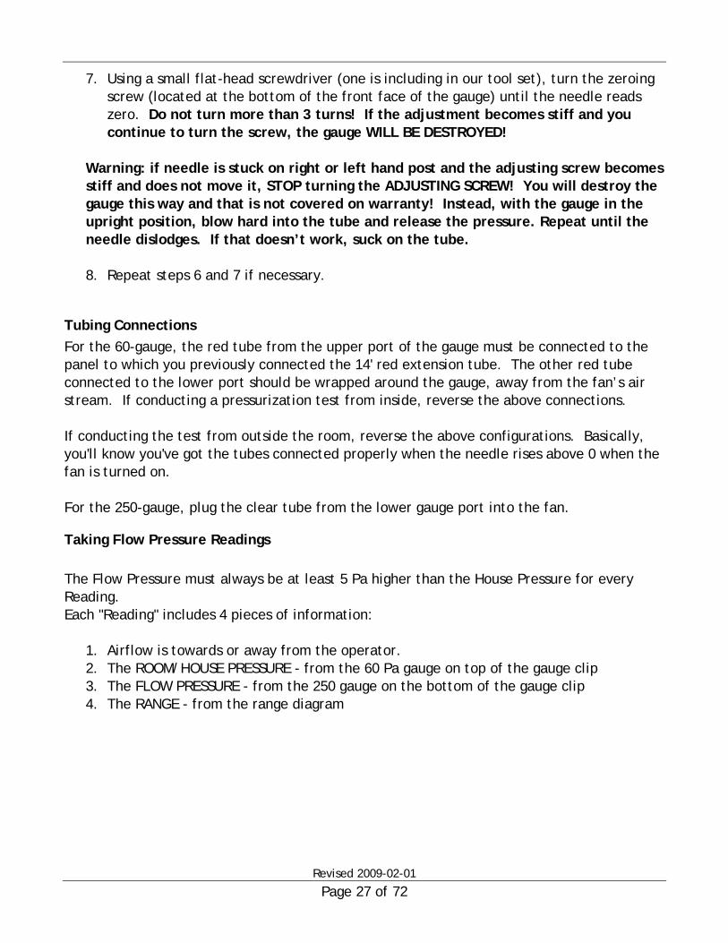
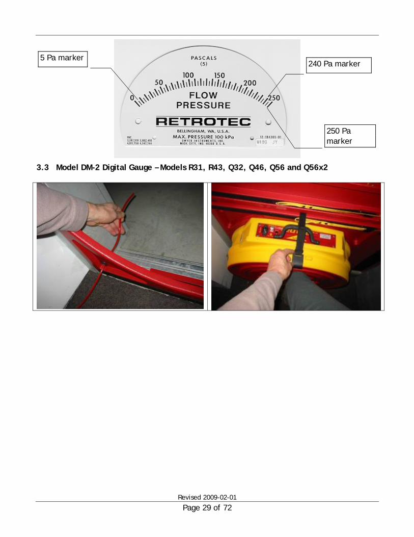
3.3 Model DM-2 Digital Gauge – Models R31, R43, Q32, Q46, Q56 and Q56x2
240 Pa marker
250 Pa marker
5 Pa marker

Revised 2009-02-01
Page 30 of 72
Red tube is passed through Panel Fan is put in place and strap connected
Power cord connected

Revised 2009-02-01
Page 31 of 72
2200 Fan for use with DM-2A: yellow tube and Ethernet style plug connected.
2200 Fan connections on DM-2A: yellow & red tube and Ethernet style plug connected.
Air movement near the DM-2A or DM-2 will cause fluctuations.
To reduce the effect, connect the blue and green tubes to the reference ports. Normally, this is not needed.
2100 Fan for use with DM-2: yellow tube and speed control plug connected.
2100 Fan connections on DM-2: yellow & red tube connected to DM-2 with remote manual speed control box.

Revised 2009-02-01
Page 32 of 72
Taking Digital Gauge Readings DM-2 and DM-2A operation 1) Make the tubing connections as described previously 2) Set the Auto Zero on. 3) Set the Mode for the results required. 4) Set time averaging using the [Time Avg] key; set it to 8. Adjust upwards if readings
fluctuate too much. 5) Adjust the fan speed.
a) DM-2A. Press [Set Pressure] [5] [0] [Enter] and the fan will attempt to achieve and hold 50Pa of room pressure.
b) DM-2 Adjust the manual remote speed control knob to get the desired pressure. 6) Change the range if the flow is TOO LOW according to the DM-2. If OK, take your
readings.

Revised 2009-02-01
Page 33 of 72

Revised 2009-02-01
Page 34 of 72
4 Using Flow Range Configurations In this chapter, we’ll explore how and when to use the range configuration options on your fan. We’ll examine how ranges affect air flow, the ranges that are available and what range to use in a particular test situation.
4.1 Principles of Door-fan Air Flow Ranges A simplified way to look at how a door fan measures flow is to think of it as a large pipe. As the fan speeds up, a suction pressure develops in the pipe that causes air to flow. More suction = more flow. By measuring this suction pressure (called Flow Pressure) the door fan is able to read out in units of flow. As the fan slows down the Flow Pressure becomes too small to accurately measure and a restriction is place in front of the fan so the suction pressure required increases to the point where it can be accurately measured again. By providing a set of flow restricting plates with ever smaller holes, the Retrotec door fan can measure flows from a miniscule 5 cfm to an enormous 8300 CFM (2 to 3917 liters per second or 8 to 14,100 cubic meters per hour). As the flow rate requirement decreases (such as in tighter buildings), the size of the fan inlet must decreased to maintain a high and accurately readable Flow Pressure. Each inlet size has a pre-established configuration or range. Ranges are somewhat analogous to gears in a standard transmission car. The slower you go, the lower the gear. Here, the lower the flow the smaller the hole.
4.2 Range Selection Criteria The greater the flow pressure, the greater the accuracy so the most restrictive range (smallest hole in front of the fan) should be used. This will result in the fan running at the highest speed which in general is better for cooling the fan. Another criterion applies for multi-point tests where it is more convenient to perform the complete test without taking the time to change ranges in mid test. That is one good reason why fans have many ranges. In European countries where their use 50 Hz power, range selection becomes more critical because their fans will run 20% slower so there is not as much difference between minimum and maximum flow on any given range.
Revised 2009-02-01
Page 35 of 72
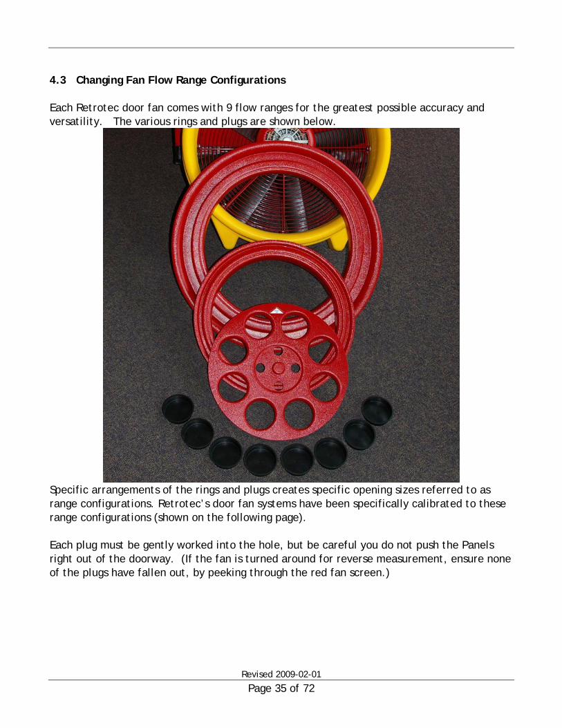
4.3 Changing Fan Flow Range Configurations Each Retrotec door fan comes with 9 flow ranges for the greatest possible accuracy and versatility. The various rings and plugs are shown below.
Specific arrangements of the rings and plugs creates specific opening sizes referred to as range configurations. Retrotec’s door fan systems have been specifically calibrated to these range configurations (shown on the following page). Each plug must be gently worked into the hole, but be careful you do not push the Panels right out of the doorway. (If the fan is turned around for reverse measurement, ensure none of the plugs have fallen out, by peeking through the red fan screen.)

Revised 2009-02-01
Page 36 of 72
Range configuration table
Open (22)
A
B
C8
C6
C4
L4
L2
L1

Revised 2009-02-01
Page 37 of 72
Range C8 has 8 large and 4 small holes open. C6 has the 2 bottom holes plugged and so on for all ranges except in the rare instance when the L ranges are used, the holes must be taped shut.
4.4 Range Selection Procedure Start on Range B with 2 rings attached and the plate with 8 holes off. Adjust the fan speed to your desired room pressure(s). If your DM-2 says “TOO LOW” on the second channel you must change the C8 range. Continue to add plugs per the until “TOO LOW” goes away. Try for the most restrictive range with the fan at its highest speed to yield the best accuracy. If you cannot achieve your desired room pressure(s) with the fan at full speed, take rings off until you can. If using analog gauges or the DM-2 is reading pressure on Channel B, the Flow Pressure must be more than double the Room Pressure but Never let the Room/House Pressure rise above 60 Pa. Range 22 is for large leaky buildings and L1 is for measuring the leakage of a shoe box. Try them out on different size rooms and buildings.
C8
DM-2 mark II
RangeConfig
Speed
Device
ZeroTimenBaseline
Set
Mode
Pressure
Dual Channel Digital Micromanometer and Control
2s On0.60- - - -
PrA
PrB
0.00Pa
0.00
C8 Retrotec 3000
Pa
Range Configuration set to Range C8 Once you have found the correct range, Press the [Range Config] key until the correct range appears in the display.

Revised 2009-02-01
Page 38 of 72
4.5 Cannot Achieve Desired Room Pressure with Range – Open(22) If the room/house to be measured has an excessive amount of leakage to the point where a single fan unit, on the Open range running at maximum speed cannot reach the required pressure, try one of the following solutions:
Option 1 Use a second fan to produce more flow and add the flow readings. Do not add flow pressure readings – only flow readings can be added.
Option 2 Instead of testing to 50 Pascals, test at a lower pressure and use the @-Pressure feature to predict what the flow would be at a given pressure..
Option 3 Have leaks sealed until the proper room/house pressure can be obtained. Inspect the room/house to ensure that all dampers, windows, and doors are closed.
4.6 Flow Ranges and Flow Direction Always start in the Flow Away position (fig. 1). You will know that your fan is in the “flow away” position, because the red fan screen will be facing outboard to the exterior of the building envelope. In the Flow Toward position, the red fan screen will be facing the inside of the building envelope (fig. 2). Adjust speed till room pressure is reached. Fan must be running at least at half speed and flow pressure must be greater than room pressure. If not, insert the Range-A plate and keep changing to lower ranges until motor is at least half speed. Remember that the Flow pressure must be greater than the room pressure.

Revised 2009-02-01
Page 39 of 72
Fig. 1 – Flow Away Fig. 2 – Flow Toward

Revised 2009-02-01
Page 40 of 72
5 Appendix A; Retrotec DM-2 & DM-2A – Two Channel Digital Gauge Use “QuickGuide-DM2MkII.pdf” for setting up and using the gauge. Use the Quick Guide for your system for understanding how to operate your door fan system. Introduction Congratulations on the purchase of your new DM-2 Digital Gauge. The DM-2 is the outcome of years of development work and decades of testing experience; it’s the most advance instrument of its type. Combined with Retrotec’s “Digital” fans, this system represents the state-of-the-art for air-tightness testing, enclosure leakage measurement and building performance assessment.
5.1 Features at a glance Dual-Channel Pressure Measurement - Simultaneous display of both Room Pressure and Flow Pressure - 2 independent differential-pressure channels with ranges from –1250 Pa to +1250Pa - Support for pressure readings in Pa, Inches of Water Column (in wc), and Pounds/ft2
(PSF) Auto-Zeroing - Automatically, at 10 second intervals, zeros both pressure channels adjusting for
changes in temperature and position. Time Averaging - Supports 8 different time averaging periods, off, 1sec, 2sec, 4sec, 8sec, 10sec,
20sec, 1min, 2min. - “Box-car averaging” updates the display every second with the new average for the
period. No more waiting for your display to update when performing long-term averaging!
Direct Air Flow Measurement for all Major Door-fans - The DM-2 will calculate and display the fan air flow almost all major door-fans on
the market including: o Retrotec Model 900 Door-fan o Retrotec Model 2000 Door-fan o Retrotec Model 3000 Door-fan o Retrotec Duc-Testing System R31 o Retrotec Duc-Testing System Q32 o Minneapolis Blower Door Model 3 o Minneapolis Blower Door Model 4 o Infiltec Model E3

Revised 2009-02-01
Page 41 of 72
- Supports various units of flow (cfm, L/s, m3/s and m3/h) Automatic Fan Control Modes
The DM-2A (DM-2 with Automatic Control) allows the user to control their “digital” fan from their gauge. The DM-2A provides the ability to control and adjust fan speed (Set Speed) and provides closed-loop control of either flow pressure (Set Flow) or room pressure (Set Pressure). The Set Pressure functionality is especially useful when sealing or changing the openings in an enclosure. Setting the gauge to Set Pressure = 50, for example, will cause the gauge to control the fan so that 50Pa pressure is constantly maintained. As you search for and seal leaks, the fan will slow down in order to provide less flow and keep you at 50Pa.
Advanced “on-the-fly” Calculations The DM-2 provides a number of advanced calculations that are continuously updated as your door fan test readings change. Theses include:
• Effective Leakage Area (EfLA) • Equivalent Leakage Area (EqLA) • Air Changes per Hour (Flow divided by Volume) • Permeability and SLR (Flow divided by Area) • Normalized Leakage Area (Leakage Area divided by Area)
@25 and @50 Pressure Extrapolation Modes
Can’t get to exactly 25 or 50 Pa? Not a problem with the DM-2. The DM-2’s @-Pressure mode allows you to view the Flow or Advanced Calculation at your desired pressure, even if you can’t reach it or can’t achieve stability. In fact each reading/calculation can have its own unique @-pressure, so you can view Flow@50Pa and Leakage@4Pa (for example). If you require an exact test pressure of say, 15.2 Pa; no problem, you can set your @ pressure at 15.2 Pa and the DM-2 will tell you what the result would be had you achieved the exact test pressure of 15.2 Pa.

Revised 2009-02-01
Page 42 of 72
5.2 Keypad - [Mode] The DM-2 has the capability to display and calculate a variety of measurements and display those measurements in a variety of units. The [Setup] button is used to enable or disable the display of each of the various modes. The [Setup] button is also used to configure the units of measurement for each mode. Configuration of the device is saving in non-volatile memory so, with a few simple keystrokes, the DM-2 can be easily configured to display only the specific measurements required for a specific standard and the appropriate units. Use the [Mode] button to scroll the lower (PrB) display through the measurements that you have configured. The Upper Display (PrA) always displays Channel A pressure in your selected units.
Pressure B
Flow
EqLA
EfLA
Air Changes
Flow/Area
EqLA/Area
Velocity
Velocity Flow
Mode
Flow: Calculated Flow though the fan EqLA: Equivalent Leakage Area being measured EfLA: Effective Leakage Area being measured ACH: Air Changes per Hour Flow/Area: Flow divided by the Area that you have input into the Setup menu EqLA/Area: EqLA divided by the Area that you have input into the Setup menu Velocity: Air velocity (requires installation of a pitot tube) Velocity Flow: Flow calculated from the velocity and cross-sectional area.

Revised 2009-02-01
Page 43 of 72
5.3 Keypad - [Range/Config] Each flow device supports various range configurations. For example, the Retrotec 2000 series door-fan has 11 flow ranges (Open, A, B, C8, C6,C4, C2, C1, L4, L2, L1). Use the [Range/Config] button to select the flow range that you are currently using. This setting affects all calculated values.
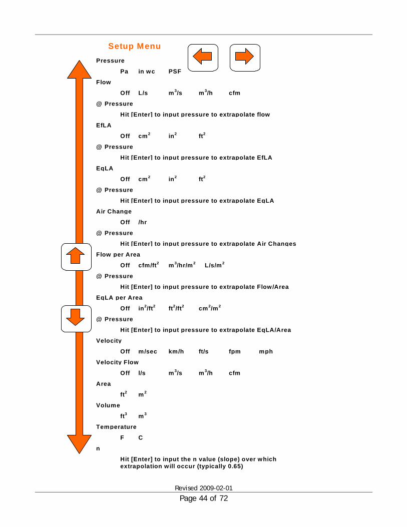
5.4 Keypad - [Setup] Perhaps the most powerful feature of the DM-2 is its ability to calculate, on the fly, virtually all of the measurement values that you will require in the field. This capability gives you the ability to quickly spot-check that you house or enclosure measurements are within or not within your standard’s requirements. The [Setup] menu allows you to configure the DM-2 to show you the calculations that you want to see and suppress the calculations that you don’t want to see or don’t use. For example, if you never use EqLA, then you can configure the DM-2 to never display EqLA. The [Setup] menu also allows you to configure the units that you want to view your measurements in. Once you enter the [Setup] menu, use the arrow keys (2, 6, 8, 4) to scroll though the [Setup] menu. Use the up/down keys to scroll through the various measurements that can be displayed. Use the left/right keys to turn the measurement off and to select the units. In the [Setup] menu, you will also find the ability to enter volumes, areas and extrapolated pressures. These entered values are used to perform advanced calculations (like flow / floor-area). When you are finished, hit [Enter] to save your changes. At this point in time, your changes are not saved across power on/off. The final version of the DM-2 will preserve your setting across power on/off.
Revised 2009-02-01
Page 44 of 72
Flow
Off L/s m3/s m3/h cfm
@ Pressure
Hit [Enter] to input pressure to extrapolate flow
EfLA
Off cm2 in2 ft2
@ Pressure
Hit [Enter] to input pressure to extrapolate EfLA
EqLA
Off cm2 in2 ft2
Air Change
Off /hr
Flow per Area
Off cfm/ft2
EqLA per Area
Off cm2/m2ft2/ft2
m3/hr/m2
Velocity
Off km/hm/sec ft/s fpm mph
Velocity Flow
Off m3/sl/s m3/h cfm
Area
ft2 m2
Volume
ft3 m3
Temperature
F C
n
Hit [Enter] to input the n value (slope) over which extrapolation will occur (typically 0.65)
Pressure
Pa in wc PSF
Setup Menu
@ Pressure
Hit [Enter] to input pressure to extrapolate EqLA
@ Pressure
Hit [Enter] to input pressure to extrapolate Air Changes
L/s/m2
@ Pressure
Hit [Enter] to input pressure to extrapolate Flow/Area
in2/ft2
@ Pressure
Hit [Enter] to input pressure to extrapolate EqLA/Area

Revised 2009-02-01
Page 45 of 72
5.5 Keypad - [Baseline] Baseline allows you to measure the background (baseline) pressure in the enclosure before you begin testing. Once measured, the DM-2 will automatically subtract this baseline pressure from your Pa measurements. Hit the [Baseline] button once to begin acquiring the background pressure. The DM-2 averages the background pressure for the duration of the acquisition period. Hit [Enter] once you feel that you have acquired long enough. This will set the unit into Baseline mode, display the baseline pressure in the top left corner of your screen and begin subtracting that value from Pa
5.6 Keypad - [Time Avg] The [Time Avg] button starts time averaging the display. Time averaging is displayed under the “Time” label. Regardless of your averaging value, the display will update with a new value every second.
5.7 Keypad - [Auto Zero] Turns on/off auto-zero. With Auto-zero on, the gauge will automatically zero the gauge every 10 seconds.
5.8 Keypad - [Set Pressure] [Set Flow] [Set Speed] These functions will allow the user to control the fan to a set speed, flow pressure or room pressure. These features will be available in future versions of the DM-2 and Retrotec Door-fan.
5.9 Keypad - [Device] Switches between various Retrotec Door-fans and other manufacture’s devices.
5.10 Keypad - [@] Toggles pressure extrapolation on and off. Using this function, the DM-2 will display your
selected measurement extrapolated from your current test condition to your desired test
condition.
For example, your testing standard might dictate that you analyze your enclosure at 50Pa but due to equipment or other limitation, you might only be able to generate

Revised 2009-02-01
Page 46 of 72
40Pa of pressure. By setting 50Pa as your extrapolation pressure in the setup menu, the DM-2 will calculate and display the readings extrapolated to 50Pa.
5.11 DM-2 Mk I Display and Buttons
Auto Zero (On / Off)
Time Averaging
Extrapolation Exponent Temperature
Baseline Status
Channel A Pressure Channel B Display
Off Off .65 - - - - Acquiring PrA
Flow
25.00 Pa
3800.10 cfm @ 25.0 Pa
Target Speed %: 50 %
Enclosure Vol. = 1000m3
Open(22) Retrotec 2000
Control Mode Message
Volume & Area Input and display Device in Use
Range/Configuration for device
Calculation Mode

Revised 2009-02-01
Page 47 of 72
DDMM--22 QQuuiicckk SSttaarrtt GGuuiiddee
Connect the supplied Umbilical Cord to the DM-2 as shown below.
Then, connect the other end of the Umbilical to the fan top as shown below. The red reference tub that goes through your door-panel or cloth must be positioned on the exterior of your enclosure, at least 10 feet from the fan

Revised 2009-02-01
Page 48 of 72
Controlling the Fan with the DM-2
There are several ways to control your fan using the DM-2.
• Set Fan Speed. Using the fan speed button "9" you can set your fan speed to any % you want. (Example: 5%, 25% 50% 100%)
• Set Flow Pressure. Using the set flow button "8" you can set the flow pressure you want. The fan will then adjust it self up or down to maintain a consistent flow.
• Set Room Pressure. Using set pressure button "7" you can set your desired room pressure. The fan will then adjust it self up or down to maintain that consistent room pressure.
Selecting your Fan with the DM-2
The DM-2 Supports a number of RETROTEC Fans as well as fans not manufactured by Retrotec.. You can select your fan by using the Device button “0”. The following Fans are supported:
Retrotec 900 series Retrotec 2000 series Retrotec 3000 series Retrotec DU100 Retrotec DU200 Minneapolis 3 Minneapolis DucTester Infiltec E3

Revised 2009-02-01
Page 49 of 72
5.12 Configuring and Using the DM-2 for Specific Standards
CGSB 149.10 Enter the [Setup] menu and configure the DM-2 as follows:
* Pressure ...............Pa
* Flow ....................l/s
* @ Pressure ............25.0 Pa
EfLA.....................Off
@ Pressure .............[does not matter]
* EqLA ....................10.0 Pa
Air Changes............Off
@ Pressure .............[does not matter]
Flow per Area .........Off
@ Pressure .............[does not matter]
* EqLA per Area.........cm2/m2
* @ Pressure .............10.0 Pa
Velocity ...............Off
Velocity Flow..........Off
* Area.....................m2
Volume .................m3
Temperature ..........C
Cross Area .............[does not matter]
Enclosure Volume ....n/a
Enclosure Area ........n/a
* n.........................0.65
* denotes parameters that are specifically mentioned in the standard. Other parameters may be optionally enabled.
1. Assess and measure the Envelope Area as specified in the standard. 2. Use the [Mode] button to scroll to the EqLA/Area mode. 3. Hit [Enter] and input the Envelope Area as measured in step 1. 4. Conduct Door-fan test at 25.0 Pa or as specified in the standard. 5. Use the [@] button to display the Flow @ 25.0 Pa and the EqLA @ 10.0 Pa 6. Results for EqLA and NLA (=EqLA/Area) may be read directly from the DM-2

Revised 2009-02-01
Page 50 of 72
DS/EN 13829 Enter the [Setup] menu and configure the DM-2 as follows:
* Pressure ..................Pa
* Flow .......................m3/h
* @ Pressure ...............50.0 Pa
EfLA .......................Off
@ Pressure................[does not matter]
EqLA .......................10.0 Pa
* Air Changes.............../h
* @ Pressure................50.0 Pa
* Flow per Area............m3/h/m2
* @ Pressure................50.0 Pa
EqLA per Area............off
@ Pressure................[does not matter]
Velocity ..................Off
Velocity Flow ............Off
* Area .......................m2
Volume....................m3
Temperature .............C
Cross Area ................[does not matter]
Enclosure Volume .......n/a
Enclosure Area...........n/a
n ...........................0.65
* denotes parameters that are specifically mentioned in the standard. Other parameters may be optionally enabled.
DS/EN 13829 is a multi-point test and cannot be completed with only a DM-2. The DM-2 can provide a quick single-point check of the enclosure however.
Assess and measure the Envelope Area as specified in the standard.
1. Assess and measure the Net Floor Area as specified in the standard. 2. Assess and measure the Envelope Area which is the total area of all conditioned surfaces
(walls, floors, and ceilings) 3. Assess and measure the Internal Volume of the building as specified in the standard. 4. Use the [Mode] button to scroll to the Air Chg mode. 5. Hit [Enter] and input the Internal Volume as measured in step 3. 6. Use the [Mode] button to scroll to the Flow/Area mode. 7. Hit [Enter] and input either:
a. The Envelope Area from Step 2. if you wish to display Air Permeability as specified in the standard.
b. The Net Floor Area from Step 3. if you wish to display Specific Leakage Rate as specified in the standard.

Revised 2009-02-01
Page 51 of 72
8. Use the [@] button to display the Flow @ 50.0 Pa, Air Changes @ 50.0 Pa, and either Air Permeability or Specific Leakage Rate @ 50.0 Pa
9. Results may be read directly from the DM-2 10. In order to record both Air Permeability and Specific Leakage Rate, you will need to re-enter
the different Areas from Steps 1. and 2.

Revised 2009-02-01
Page 52 of 72
ATTMA: TS-1 Enter the [Setup] menu and configure the DM-2 as follows:
* Pressure ..................Pa
* Flow .......................m3/h
* @ Pressure ...............50.0 Pa
EfLA .......................Off
@ Pressure................[does not matter]
EqLA .......................10.0 Pa
Air Changes.............../h
@ Pressure................50.0 Pa
* Flow per Area............m3/h/m2
* @ Pressure................50.0 Pa
EqLA per Area............off
@ Pressure................[does not matter]
Velocity ..................Off
Velocity Flow ............Off
* Area .......................m2
Volume....................m3
Temperature .............C
Cross Area ................[does not matter]
Enclosure Volume .......n/a
Enclosure Area...........n/a
n ...........................0.65
* denotes parameters that are specifically mentioned in the standard. Other parameters may be optionally enabled at the user’s discretion.
ATTMA TS-1 13829 is a multi-point test and cannot be completed with only a DM-2. The DM-2 can provide a quick single-point check of the enclosure however.
Assess and measure the Envelope Area as specified in the standard.
1. Use the [Mode] button to scroll to the Flow/Area mode. 2. Hit [Enter] and input the either:
a. The Envelope Area if you wish to display Air Permeability as specified in the standard. b. The Exposed Envelope Area is you wish to display Air Leakage Index as specified in the
standard. 3. Use the [@] button to display the Flow @ 50.0 Pa, Air Changes @ 50.0 Pa, and either Air
Permeability or Air Leakage Index @ 50.0 Pa 4. Results may be read directly from the DM-2 5. In order to record both Air Permeability and Air Leakage Index, you will need to re-enter the
different Areas from steps 1. and 2

Revised 2009-02-01
Page 53 of 72
Title-24-California Enter the [Setup] menu and configure the DM-2 as follows:
* Pressure ..................Pa
* Flow .......................cfm
* @ Pressure ...............25.0 Pa
EfLA .......................Off
@ Pressure................[does not matter]
* EqLA .......................25 Pa
Air Changes...............On
@ Pressure................[does not matter]
Flow per Area............Off
@ Pressure................[does not matter]
* EqLA per Area............cfm/f2
* @ Pressure................25 Pa
Velocity ..................Off
Velocity Flow ............Off
* Area .......................f2
Volume....................f3
Temperature .............F
Cross Area ................[does not matter]
Enclosure Volume .......n/a
Enclosure Area...........n/a
* n ...........................0.65
1. Assess and measure the Conditioned Floor Area CFA in f2 as specified in the Standard. 2. Use the [Mode] button to scroll to the EqLA/Area mode. 3. Hit [Enter] and input the CFA as measured in step 1. 4. Conduct Door-fan test at 25.0 Pa or as specified in the standard. 5. Use the [@] button to display the Flow @ 25.0 Pa. 6. Results for default, heating only analysis may be read. (EqLA/Area) may be read 7. directly from the DM-2

Revised 2009-02-01
Page 54 of 72
6 Appendix B - Manual Airflow and Leakage Area Results
6.1 Calculating Airflow Manually You will want to calculate results manually when: 1. You are not using a computer. 2. You are testing a very large or leaky building and are using more than two fans. The following tables provide the CFM results for a given Flow Pressure. Manual calculations are really only appropriate for Single Reading Tests. It is possible to do a Multi-Reading Test manually and attempt to plot out the results on log-log graph paper, but it is not recommended. Two things must be known to establish airflow; the door-fan range and the flow pressure. (For more information on door-fan ranges, see the Section 5.0). The flow pressure is the pressure difference across the fan inlet. If using a computer program, it should automatically correct for the indoor - outdoor temperature difference. If using the manual table you must apply the temperature correction factors as appropriate. A 20 degree F difference produces a 2% correction. See the following tables for further information. If the flow from the fan is towards the operator (pressurizing), then the flow pressure on the gauge will be too high by an amount equal to the room pressure. Retrotec's software automatically corrects for this. If you are calculating flows manually, you must do the subtraction yourself. Simply deduct the room pressure from the flow pressure to arrive at the true Final Flow (FF) pressure when the fans are blowing towards the operator and gauges.

Revised 2009-02-01
Page 55 of 72
6.2 Manual CFM Tables The following two pages contain the data and instructions on how to calculate flow and ELA manually.
How to use this table: If flow away from operator, start at Step 1. For flow towards operator, start at Step 5. 1. Adjust the fan speed to get the desired Room Pressure with the airflow away from the operator. 2. Read Flow Pressure Gauges. Must be greater than room pressure and 9 Pa. 3. Locate each Flow Pressure in left column. 4. Read the CFM from underneath the appropriate Range column. 5. Adjust the fan speed to get the desired Room Pressure with the airflow towards the operator. 6. Read Flow Pressure Gauges. 7. Subtract the Room Pressure from each Flow Pressure. Result must be greater than room pressure and 10
Pa. 8. Locate each reduced Flow Pressure in left column. 9. Read the CFM from underneath the appropriate. Flows on this table may vary from the more accurate computer output for several reasons.
• The flow pressure is corrected for room pressure which is not known so approximated to equal flow pressure.
• The computer corrects each input for gauge error • The computer may add a fan correction factor K4
In spite of this, manually calculated results will typically be within 2% of the computer result.

Revised 2009-02-01
Page 56 of 72
6.3 Manual Table: Liters/second at 10 Pa and ELA at 10 Pa For Retrotec 2000 Series fans only.
Flow in liters/ second at 10Pa Equivalent Leakage Area at 10Pa Range 22 A B C8 C4 C2 C1 22 A B C8 C4 C2 C1 l./s. l./s. l./s. l./s. l./s. l./s. l./s. cm2 cm2 cm2 cm2 cm2 cm2 cm2
10 789 404 243 118 61 27 16 3171 1623 977 474 247 109 63 15 963 489 296 144 76 36 21 3869 1966 1190 579 304 145 83 20 1110 562 341 166 88 43 24 4463 2259 1371 667 353 172 98 25 1242 626 381 186 98 49 28 4990 2518 1530 746 395 196 111 30 1361 685 417 203 108 54 31 5468 2753 1675 817 434 217 123 35 1470 739 450 219 117 59 33 5909 2970 1807 882 469 236 133 40 1572 789 480 235 125 63 36 6319 3172 1931 943 502 253 143 50 1759 881 537 262 140 71 40 7070 3542 2158 1054 563 285 161 60 1927 965 588 288 154 78 44 7747 3877 2363 1156 618 313 177 70 2082 1042 635 311 167 84 48 8368 4186 2551 1249 669 339 192 80 2225 1113 678 332 178 90 51 8944 4474 2727 1336 717 363 206 90 2359 1180 719 353 190 96 55 9483 4745 2892 1418 762 385 219 100 2486 1244 758 372 200 101 58 9990 5001 3048 1495 805 407 232 110 2605 1305 795 390 211 106 61 10470 5245 3196 1569 847 427 244 120 2719 1363 831 408 221 111 63 10926 5478 3338 1640 886 447 255 130 2827 1418 864 425 230 116 66 11362 5701 3474 1708 925 466 266 140 2930 1472 897 441 239 120 69 11778 5917 3605 1774 962 484 277 150 3030 1524 928 457 248 125 71 12178 6124 3732 1837 998 502 287 160 3125 1574 959 472 257 129 74 12562 6326 3854 1899 1033 519 297 170 3217 1622 988 487 265 133 76 12932 6520 3972 1958 1067 536 307 180 3306 1669 1017 502 274 137 79 13288 6710 4088 2016 1100 552 316 190 3392 1715 1045 516 282 141 81 13633 6894 4200 2073 1133 568 326 200 3475 1760 1072 529 290 145 83 13967 7074 4309 2128 1165 584 335 210 3555 1803 1098 543 298 149 86 14290 7249 4415 2182 1197 599 344 220 3633 1846 1124 556 305 153 88 14603 7420 4519 2234 1228 614 353 230 3709 1888 1150 569 313 156 90 14907 7587 4620 2286 1258 629 362 240 3782 1928 1174 581 320 160 92 15203 7751 4720 2336 1288 644 370 250 1968 1199 594 328 164 94 7911 4817 2386 1318 658 379 260 2007 1222 606 335 167 96 8068 4912 2435 1347 672 387 270 2046 1246 618 342 171 98 8222 5006 2483 1375 686 395 280 2083 1268 629 349 174 100 8374 5098 2530 1404 700 403 290 2120 1291 641 356 178 102 8522 5188 2576 1432 714 412 300 2157 1313 652 363 181 104 8668 5277 2621 1460 727 420
Flow Pressure (Pa)
310 2192 1335 663 370 184 106 8812 5364 2666 1487 741 427
Revised 2009-02-01
Page 57 of 72
6.4 Manual Table: Liters/second at 25 Pa and ELA at 25 Pa
For Retrotec 2000 Series fans only. Flow in liters/ second at 25 Pa Equivalent Leakage Area at 25Pa
Range 22 A B C8 C4 C2 C1 22 A B C8 C4 C2 C1 l./s. l./s. l./s. l./s. l./s. l./s. l./s. cm2 cm2 cm2 cm2 cm2 cm2 cm2
10 789 404 243 118 61 27 16 3171 1623 977 474 247 109 6315 963 489 296 144 76 36 21 3869 1966 1190 579 304 145 8320 1110 562 341 166 88 43 24 4463 2259 1371 667 353 172 9825 1268 640 385 187 97 42 25 3223 1627 978 476 246 106 6230 1385 697 420 205 107 48 28 3520 1773 1068 520 271 121 7135 1493 750 453 221 116 53 31 3794 1908 1152 561 294 135 7840 1593 800 484 236 124 58 33 4050 2034 1229 600 315 147 8550 1778 891 540 264 139 66 38 4519 2265 1372 670 354 169 9760 1945 974 590 289 153 74 42 4943 2475 1501 734 389 188 10870 2098 1050 637 312 166 81 46 5333 2669 1619 792 421 205 11780 2240 1121 681 333 178 87 50 5695 2849 1730 847 452 221 12690 2373 1188 722 354 189 93 53 6033 3019 1834 899 480 236 135100 2499 1251 760 373 200 98 56 6352 3180 1933 948 508 250 143110 2618 1312 797 391 210 103 59 6654 3334 2026 995 534 263 151120 2731 1369 832 409 220 108 62 6942 3481 2116 1039 559 276 158130 2839 1425 866 426 229 113 65 7216 3621 2202 1082 583 288 165140 2942 1478 899 442 239 118 68 7478 3757 2284 1124 607 300 172150 3041 1529 930 458 248 122 70 7730 3888 2364 1164 630 311 179160 3136 1579 960 473 256 127 73 7972 4015 2441 1202 652 322 185170 3228 1628 990 488 265 131 75 8205 4138 2516 1240 673 333 191180 3316 1675 1018 502 273 135 78 8430 4257 2589 1277 695 343 197190 3402 1720 1046 516 281 139 80 8647 4373 2660 1312 715 354 203200 3484 1765 1073 530 289 143 82 8857 4486 2729 1347 736 364 209210 3565 1808 1100 543 297 147 85 9061 4597 2796 1381 756 374 215220 3642 1851 1126 556 305 151 87 9259 4705 2861 1415 775 383 221230 3718 1892 1151 569 313 155 89 9451 4810 2926 1447 794 393 226240 3791 1933 1176 582 320 158 91 9637 4913 2988 1479 813 402 232250 1973 1200 594 327 162 93 5015 3050 1510 832 411 237260 2012 1223 606 335 165 95 5114 3110 1541 851 420 243270 2050 1247 618 342 169 98 5211 3169 1571 869 429 248280 2088 1270 630 349 172 100 5307 3227 1601 887 438 253290 2124 1292 641 356 176 102 5400 3284 1630 905 447 258300 2161 1314 653 363 179 104 5493 3340 1659 922 456 263
Flow Pressure (Pa)
310 2196 1336 664 370 183 106 5583 3396 1688 940 464 268

Revised 2009-02-01
Page 58 of 72
6.5 Manual Table: CFM at 50 Pa and 25 Pa Table
For Retrotec 2000 Series fans only. cu.ft. / minute at 50 Pa cu.ft. / minute at 25Pa
Range 22 A B C8 C4 C2 C1 22 A B C8 C4 C2 C1 cfm cfm cfm cfm cfm cfm cfm cfm cfm cfm cfm cfm cfm cfm
10 15 20 25 2686 1356 815 397 205 88 5230 2934 1478 890 434 226 101 5935 3163 1590 960 468 245 112 6540 3376 1695 1025 500 263 123 7150 3833 1922 1153 563 291 123 73 3767 1888 1143 558 295 141 8160 4181 2094 1260 615 321 141 83 4121 2063 1251 612 324 156 9070 4502 2253 1358 664 348 157 92 4445 2224 1350 661 351 171 9880 4800 2402 1450 710 374 171 100 4747 2375 1442 706 376 184 10590 5079 2543 1536 752 398 185 107 5029 2517 1529 749 400 196 112100 5342 2676 1618 793 421 197 114 5295 2651 1611 790 423 208 119110 5592 2802 1696 832 443 209 121 5547 2779 1689 829 445 219 126120 5829 2924 1770 869 464 220 127 5786 2901 1764 866 466 230 132130 6056 3040 1841 905 484 230 133 6015 3019 1835 902 486 240 138140 6273 3152 1910 939 504 241 139 6233 3132 1904 937 506 250 143150 6482 3261 1976 972 523 251 145 6443 3241 1971 970 525 259 149160 6682 3366 2041 1005 541 260 150 6645 3346 2035 1002 543 269 154170 6875 3468 2103 1036 559 269 156 6839 3449 2097 1034 561 278 159180 7062 3567 2163 1066 577 278 161 7027 3548 2158 1064 579 286 165190 7242 3663 2222 1096 595 287 166 7208 3645 2217 1094 596 295 170200 7416 3757 2279 1125 611 296 171 7383 3740 2274 1123 613 303 174210 7585 3849 2335 1153 628 304 176 7553 3832 2330 1151 630 311 179220 7749 3938 2390 1181 645 312 181 7718 3922 2385 1179 646 319 184230 7908 4026 2443 1208 661 320 185 7878 4009 2439 1206 662 327 189240 8063 4111 2495 1235 676 328 190 8033 4096 2491 1233 678 335 193250 4195 2547 1261 692 336 195 4180 2542 1259 694 343 198260 4278 2597 1287 707 344 199 4263 2592 1285 709 350 202270 4359 2646 1312 723 351 204 4344 2642 1310 724 358 207280 4438 2694 1336 738 359 208 4423 2690 1335 739 365 211290 4516 2742 1361 753 366 212 4502 2738 1359 754 373 215300 4593 2788 1385 767 374 217 4578 2784 1383 769 380 219
Flow Pressure (Pa)
310 4668 2834 1408 782 381 221 4654 2830 1407 783 387 224

Revised 2009-02-01
Page 59 of 72
6.6 Temperature Correction Temperature correction is only required when there is a temperature difference across the Door-fan. Typically the temperature inside the room is the same as outside, so no temperature correction is needed. Retrotec’s E2001 Energy Software and Doorfan 3.0 software automatically correct for this temperature difference when present. If you are using software from another vendor, make sure that it also applies this correction; otherwise, your calculations will not be completely accurate. If using this table, you must apply the temperature correction factors as appropriate. A 200F difference produces a 2% correction. See the summary table at the bottom of the form, as well as the complete temperature correction tables in this section.
Multiple Fans Never add flow pressures, they aren't additive. Determine each flow separately and add flows. The simplest way to add flows is to use the tables at the end of this Section. For more precision, correct the gauge readings against a certificate of calibration.
Auto-Correct and Calculate Using Formulae This optional feature of Retrotec E2001 & Door Fan 3.0 Windows software automatically corrects:
• Gauge readings against the gauge calibration to dramatically reduce gauge errors. • Fan calibration against the Retrotec fan calibration certificate • Once these corrections are made, the formulae in “Flow Formulae” table is used to
calculate flow then leakage area if required. • Flow readings for indoor and outdoor temperature
The result is to reduce errors down from 4% to 2% for analog gauges and down to 1% for digital gauges.

Revised 2009-02-01
Page 60 of 72
6.7 Sample 1-Year Gauge Calibration Certificate One Year Calibration Certificate System
model #
System owned by
Magnificent Testing Company
for E2001ver 2.0.0 license # 149 date 2003 01 15 Good for one year from date shown. Room gauge (maximum allowable error +/- 1 Pascal) serial # >>>>>>> XXXXXX -1 to correct mult by & add gauge CR MRC error Pa 0 to 5.8 0.912 0.000 4.5 4.1 4 0.1 5.8 to 8.0 0.895 0.110 7.6 6.9 7.2 -0.3 8.0 to 12.0 1.065 -1.361 11.8 11.2 11.3 -0.1 12.0 to 18.0 1.073 -1.466 15.5 15.2 15.2 0.0 18.0 to 27.5 1.075 -1.486 19.5 19.5 19.4 0.1 27.5 to 48.0 1.116 -2.535 31.5 32.6 32.8 -0.2 48.0 to 70.0 1.000 2.500 48 50.5 50.8 -0.3 Flow gauge # 1 (maximum allowable error +/- 5 Pascals) serial # >>>>>>> XXXXXX -1 to correct mult by & add gauge CF MRC error Pa 0 to 25.5 0.961 0.000 21 20.2 20 0.2 25.5 to 39.0 0.852 2.778 31 29.2 30 -0.8 39.0 to 60.5 1.093 -6.628 51 49.1 51 -1.9 60.5 to 91.0 1.098 -6.951 80 80.9 81 -0.1 91.0 to 129.0 1.039 -1.592 105 107.6 107 0.6 129.0 to 172.0 1.081 -7.000 140 144.4 143 1.4 172.0 to 275.0 1.000 7.000 185 192.0 192 0.0 Flow gauge # 2 (maximum allowable error +/- 5 Pascals) serial # >>>>>>> XXXXXX -1 to correct mult by & add gauge CF MRC error Pa 0 to 25 1.100 0.000 20 22.0 19 0.1 25 to40 1.000 0.600 31 31.6 29 0.8 40 to 60 1.083 -0.150 50 54.0 49 -0.2 60 to 90 1.000 0.850 81 81.9 81 1.5 90 to 130 0.875 2.975 105 94.9 105 0.6 130 to 175 0.950 1.100 145 138.9 145 -0.3 175 to 275 1.000 -1.150 195 193.9 192 -2.0
all pressure readings in Pascals

Revised 2009-02-01
Page 61 of 72
6.8 Temperature Correction Table for Enclosure Depressurization
INSIDE TEMPERATURE (F)
50 55 60 65 70 75 80 85 90
-20 0.929 0.924 0.920 0.915 0.911 0.907 0.903 0.898 0.894
-15 0.934 0.930 0.925 0.921 0.916 0.912 0.908 0.904 0.899
-10 0.939 0.935 0.930 0.926 0.921 0.917 0.913 0.909 0.904
-5 0.945 0.940 0.935 0.931 0.927 0.922 0.918 0.914 0.909
0 0.950 0.945 0.941 0.936 0.932 0.927 0.923 0.919 0.914
5 0.955 0.950 0.946 0.941 0.937 0.932 0.928 0.924 0.919
10 0.960 0.955 0.951 0.946 0.942 0.937 0.933 0.929 0.924
15 0.965 0.960 0.956 0.951 0.947 0.942 0.938 0.934 0.929
20 0.970 0.965 0.961 0.956 0.952 0.947 0.943 0.938 0.934
25 0.975 0.970 0.966 0.961 0.957 0.952 0.948 0.943 0.939
30 0.980 0.975 0.971 0.966 0.962 0.957 0.953 0.948 0.944
35 0.985 0.980 0.976 0.971 0.966 0.962 0.957 0.953 0.949
OUTSIDE 40 0.990 0.985 0.981 0.976 0.971 0.967 0.962 0.958 0.953
TEMPERATURE 45 0.995 0.990 0.985 0.981 0.976 0.972 0.967 0.963 0.958
(F) 50 1.000 0.995 0.990 0.986 0.981 0.976 0.972 0.967 0.963
55 1.005 1.000 0.995 0.990 0.986 0.981 0.977 0.972 0.968
60 1.010 1.005 1.000 0.995 0.991 0.986 0.981 0.977 0.972
65 1.015 1.010 1.005 1.000 0.995 0.991 0.986 0.981 0.977
70 1.019 1.014 1.010 1.005 1.000 0.995 0.991 0.986 0.982
75 1.024 1.019 1.014 1.009 1.005 1.000 0.995 0.991 0.986
80 1.029 10.24 1.019 1.014 1.009 1.005 1.000 0.995 0.991
85 1.034 1.029 1.024 1.019 1.014 1.009 1.005 1.000 0.995
90 1.038 1.033 1.028 1.024 1.019 1.014 1.009 1.005 1.000
95 1.043 1.038 1.033 1.028 1.023 1.019 1.014 1.009 1.005
100 1.048 1.043 1.038 1.033 1.028 1.023 1.018 1.014 1.009
105 1.053 1.047 1.042 1.037 1.033 1.028 1.023 1.018 1.014
110 1.057 1.052 1.047 1.042 1.037 1.032 1.027 1.023 1.018
Multiply flow by factor to get the corrected air flow.
Depressurize Operator Inside
Flow Away
Depressurize Operator Outside
Flow Towards

Revised 2009-02-01
Page 62 of 72
6.9 Temperature Correction Table for Enclosure Pressurization
INSIDE TEMPERATURE (F)
50 55 60 65 70 75 80 85 90
-20 1.077 1.082 1.087 1.092 1.098 1.103 1.108 1.113 1.118
-15 1.071 1.076 1.081 1.086 1.091 1.097 1.102 1.107 1.112
-10 1.065 1.070 1.075 1.080 1.085 1.090 1.096 1.101 1.106
-5 1.059 1.064 1.069 1.074 1.079 1.084 1.089 1.095 1.100
0 1.053 1.058 1.063 1.068 1.073 1.078 1.084 1.089 1.094
5 1.047 1.052 1.058 1.063 1.068 1.073 1.078 1.083 1.088
10 1.042 1.047 1.052 1.057 1.062 1.067 1.072 1.077 1.082
15 1.036 1.041 1.046 1.051 1.056 1.061 1.066 1.071 1.076
20 1.031 1.036 1.041 1.046 1.051 1.056 1.061 1.066 1.070
25 1.025 1.030 1.035 1.040 1.045 1.050 1.055 1.060 1.065
30 1.020 1.025 1.030 1.035 1.040 1.045 1.050 1.055 1.059
35 1.015 1.020 1.025 1.030 1.035 1.040 1.044 1.049 1.054
OUTSIDE 40 1.010 1.015 1.020 1.025 1.030 1.034 1.039 1.044 1.049
TEMPERATURE 45 1.005 1.010 1.015 1.020 1.024 1.029 1.034 1.039 1.044
(F) 50 1.000 1.005 1.010 1.015 1.019 1.024 1.029 1.034 1.038
55 0.995 1.000 1.005 1.010 1.014 1.019 1.024 1.029 1.033
60 0.990 0.995 1.000 1.005 1.010 1.014 1.019 1.024 1.028
65 0.986 0.990 0.995 1.000 1.005 1.010 1.014 1.019 1.024
70 0.981 0.986 0.991 0.995 1.000 1.005 1.009 1.014 1.019
75 0.976 0.981 0.986 0.991 0.995 1.000 1.005 1.009 1.014
80 0.972 0.977 0.981 0.986 0.991 0.995 1.000 1.005 1.009
85 0.967 0.972 0.977 0.981 0.986 0.991 0.995 1.000 1.005
90 0.963 0.968 0.972 0.977 0.982 0.986 0.991 0.995 1.000
95 0.959 0.963 0.968 0.973 0.977 0.982 0.986 0.991 0.995
100 0.954 0.959 0.964 0.968 0.973 0.977 0.982 0.987 0.991
105 0.950 0.955 0.959 0.964 0.969 0.973 0.978 0.982 0.987
110 0.946 0.951 0.955 0.960 0.964 0.969 0.973 0.978 0.982
Multiply flow by factor to get the corrected air flow.
Pressurize Operator Inside Flow Towards
Pressurize Operator Outside Flow Away

Revised 2009-02-01
Page 63 of 72
6.10 Flow Formulae Range N K K1 K2 K3 K4 CR MF FF cfm m3 / sec in2 at CR cm2 at CR
22 0.52140 486.99 -0.070 0.87 -0.12 1 25 10 10 1756 0.8285 326 2107A 0.50300 259.04 -0.075 1.3 0 1 50 10 100 2676 1.2618 352 2271B 0.50075 159.84 -0.035 1 0 1 50 10 100 1618 0.7630 213 1373
C8 0.50250 77.418 -0.030 1 0.004 1 50 10 100 793 0.3740 104 673C4 0.49500 42.448 0.045 1.2 0.011 1 50 10 100 421 0.1985 55 357C2 0.46550 24.864 0.400 1.2 0.008 1 50 10 100 197 0.0929 26 167C1 0.47730 13.349 0.320 1.2 0.004 1 50 10 100 114 0.0538 15 97
This calibration includes both gauge and fan error combined. CR and CF come from the One Year Certificate. For Flow Towards the operator, CF must be reduced by CR before calculating flow to yield FF, the symbol for the Final Flow pressure. For Flow Away from the operator CF=FF. FF must be >=MF and (CR * K2) otherwise flow pressure is too low for accurate results. Flow in cfm = (FF-CR*K1)^N*(K+K3*FF)*K4 For m3/sec, divide by 2118.882

Revised 2009-02-01
Page 64 of 72
Manual Test Form Location: Date: Type of Test: Test Flow away from operator
Depressurize with
operator in room, or Pressurize with
operator outside room
Flow towards operator Pressurize with
operator in room, or Depressurize with
operator outside room
# RP CR FP FF Range l/s ELA RP CR FP CF FF Range l/s ELA 1 48 50.5 105 107.6 A 1307 2341 2 3 4 5 6
RP = Room Pressure gauge reading CR = Corrected Room pressure using Gauge Correction Formulae FP = Flow Pressure gauge reading CF = Corrected Flow pressure using Gauge Correction Formulae FF= CF FF= CF - CR
Range - see section 5, use 22, A, ...C1 CFM - lookup from CFM table or CFM equations. CFM / 2.119 = Liters / sec ELA = Equivalent Leakage Area, hole size in square inches = CFM/square root of room pressure/1.0755 * 2.54*2.54 cm2 # 1 details # 2 details # 3 details # 4 details # 5 details # 6 details NOTES:

Revised 2009-02-01
Page 65 of 72
Manual Test Form (Example) Location: Date: Type of Test: Test Flow away from operator
Depressurize with
operator in room, or Pressurize with
operator outside room
Flow towards operator Pressurize with
operator in room, or Depressurize with
operator outside room
# RP CR FP FF Range l/s ELA RP CR FP CF FF Range l/s ELA 1 48 50.5 105 107.6 A 1307 2341 2 3 4 5 6
RP = Room Pressure gauge reading CR = Corrected Room pressure using Gauge Correction Formulae FP = Flow Pressure gauge reading CF = Corrected Flow pressure using Gauge Correction Formulae FF= CF FF= CF - CR
Range - see section 5, use 22, A, ...C1 CFM - lookup from CFM table or CFM equations. CFM / 2.119 = Liters / sec ELA = Equivalent Leakage Area, hole size in square centimeters # 1 details # 2 details # 3 details # 4 details # 5 details # 6 details NOTES:__________________________________________________________________________________________________________________________________________________________________________________________________________________________
Revised 2009-02-01
Page 66 of 72
7 Appendix C Glossary of Definitions
60 Gauge- see Room Gauge The gauge used to measure the room pressure. Full scale is 60 Pascals (or 0.24” W.C.). It is usually located on the left and connects to the door panel by a red tube.
250 Gauge The gauge used to measure blow pressure. Full scale 250 Pascals (or 1.004” W.C.). It connects to the fan via quick connects and a clear tube.
ASHRAE The American Society of Heating, Refrigerating and Air Conditioning Engineers. Developers of standards and technical guidance relating to HVAC/R issues.
Fan As used in the text, this term means the Retrotec Infiltrometer fan unit that both flows air and provides a FLOW PRESSURE signal from which flow is measured. Also sometimes called a flow tube, flow element or Door-fan.
Center Panel A red ABS plastic molded sheet, which goes between the upper and lower panel to fill the gap.
Conditioned Space An area or volume that is normally air-conditioned or heated (i.e. inside the thermal envelope). Even though supply ducts may not discharge directly into these spaces, they are conditioned if their temperature follows indoor temperature closer than outdoor.
Depressurization The process of creating a negative pressure in the house by blowing air out of the house. Air is drawn in from outside to replace it, showing up as "geysers" when checked with an air current tester.
Envelope The surfaces composed of floor and walls and floors that separate the test volume from volume surrounding the test volume

Revised 2009-02-01
Page 67 of 72
Equivalent Leakage Area (ELA) The equivalent size of hole required in a flat plate to give the same flow rate at the Reference Pressure. In layman's terms, the ELA is the size of hole we'd have if all the building's cracks and holes could somehow be brought together. Also called: Whole Room Leakage and includes Leaks through the ceiling and below the ceiling (BCLA).
Expander Mechanism The red metal mechanism attached to the door panel that enables the panel system to expand sideways into the doorframe. It has a mechanical ratio of 5:1.
Flow Gauge The gauge used to measure flow pressure. Full scale 250 Pascals (or 1.004” W.C.). It connects to the fan via quick connects and a clear tube. It could also be the Retrotec digital micro-manometer that will measure both room and flow pressure with greater accuracy than the 60 or 250 analog gauges.
Flow Pressure The pressure difference between inside the fan and the surrounding air read off of the Door-fan's 60 and 250 pa flow gauges. It is used by the computer to calculate the airflow through the fan.
HVAC Heating Ventilating and Air conditioning system.
Infiltrometer A name used and registered by Retrotec to describe their door fan equipment. Often called fan-door or a Door-fan.
Pascal A very small metric unit of pressure. Equal to 1/249th of an inch of H2O. There are 249 Pascals in 1" Water Column (the pressure required to push water up 1" in a tube).
Pressurization The process of creating a positive pressure in the house by blowing air into the house. Air is pushed out through all the leaks, causing the smoke to move away from the operator when checked with an air current tester.

Revised 2009-02-01
Page 68 of 72
Reading A set of Room Pressure and Flow Pressure readings taken simultaneously. Sometimes referred to as a data set or point.
Restrictor Plate(s) A plate that attaches to the front of the fan that restricts flow which increases flow pressure so low flow readings may be taken. In general the flow pressure should be as high as possible for best accuracy and must greater than the room pressure.
Reference Pressure The pressure at which a result is calculated. This is usually at the test pressure. For example ELA is typically referenced to 10 Pa because it is specified that way in the Canadian standard which is the most widely used for ELA and in general. ELA is also taken at 25 Pa for some purposes because it tends to be more repeatable. Forced airchanges are usually referenced to 50 Pa, which is why it is common to see ACH50 for airchanges at 50 Pa. Or, CFM50 would be the airflow at 50 Pa. In all cases the test may be taken at a pressure close to the reference pressure and then converted by computer to the reading that it has calculated would have been read at the reference pressure. More, often the reading is taken at the reference pressure and no or fewer calculations are needed.
Room Gauge The gauge used to measure the room pressure. Full scale is 60 Pascals (or 0.24” W.C.). It is usually located on the left and connects to the door panel by a red tube. It could also be the Retrotec digital micro-manometer that will measure both room and flow pressure with greater accuracy than the 60 or 250 analog gauges.
Room Pressure The pressure difference created by the fan between inside and out, read off of the Door-fan's 60 Pa gauge. This gauge is labeled "Room/House Pressure".
Upper Panel Cover This cover is designed for cases where the optional second fan panel was purchased. In this case this panel covers the 22" diameter hole in the upper panel. Another option is an Upper Panel Cover that has 2-calibration holes cut to precise size at the factory to facilitate field calibration checks. The panel comes out with a quick pull and is used.

Revised 2009-02-01
Page 69 of 72
8 Appendix D: Troubleshooting
8.1 Motors Overheat and Shutoff
Retrotec 2000 series 120 Volt AC Motors There is a lot of variation from one motor to the next as they come from the Manufacturer. Some motors heat up more than others in spite of undergoing the same manufacturing process. All motors are tested at Retrotec facilities for 1.5 hours under full current and stress. The motors which shut off due to excess heat are rejected, and sent back to the beginning of the production line. In spite of this, users may still encounter problems in the field. What follows are some points that may be followed to remedy your specific problem.
1. Make sure the motor runs as close to full speed as possible. The faster it runs, the more air goes through the motor. A rule of thumb is to have the flow pressure over 100 Pa and the motor running near full speed. The motor heats up the most at ¾-speed where it draws 13 amps at 120 volts. At full speed the motor will draw less current!
2. Make sure the C8 plate has the cooling ports in line with the ones on the motor cover.
If the mounting indicator sign is in the correct position, this will ensure the ports are fully open.
3. Ensure that the switch on the speed controller is turned OFF at the rocker switch, not
just turned down. If left on low speed with the blade not turning, the controller and the motor will be stressed.
4. The thermal breakers that shut down the motor are not susceptible to change, (we
are told). One easy solution is to put a current meter on the fan and adjust it so the operator can see when he is pulling maximum current and therefore creating maximum heat. Let us know if you need to know how to measure the current. More current = more heat. More airflow through motor = less heat.
A more drastic solution is to change the blade or to cut a quarter inch off the blade tips and re-balance the blade to reduce the load on the motor.

Revised 2009-02-01
Page 70 of 72
8.2 Windy Conditions In windy conditions, you may find that the house/room gauge fluctuates. If this fluctuation is greater than 2 Pa due to wind buffeting, a wind damping system can be used to average out the wind and get a more stable pressure reading. In addition to a number of suggestions for obtaining better performance from your single tube system, Retrotec offers two wind-damping kits specifically designed to reduce the pressure fluctuations due to wind. The basic wind-damping kit consists of a dual-tube pressure averaging system and will work in wind conditions up to about 10 mph. The deluxe wind-damping kit (our “Wild Wind Tamer”) consists of a four-tube engineered damping system and should provide good damping results in wind conditions up to 20 mph. Using either wind-damping kit, set up the house/room gauge and tube as normal. Next, connect the open end to the T on the basic wind-damping kit or output port on the deluxe wind-damping kit. The wind-damping tubes are then placed away from the building to avoid the pressure pulse that gets created when the wind hits the wall. Cover the end of the tube with sheet material or a box to stop the wind from blowing into the end if required.
Connect open end of 14 ft. red tube to the wind damping system
14 ft. tube goes here
Center panel bar in vertical position
14 foot red tube connected
Basic Wind damping kit
View from Outdoors

Revised 2009-02-01
Page 71 of 72
9 Appendix E: Air Leakage Rates
9.1 Table of Air Leakage Rates House Leakage Standards based on floor area of: 2,250 ft2
Standard ACH50 cfm50/ft2
CGSB149.10 1.5 Airchanges/hour at 50 Pa 1.5 Canadian R-2000 1.5 0.07
ATTMA TS-1 3 cu.m/h/sq m. at 50 Pa UK, Best Practice, residential 3.4 0.16
Oregon 3.5 Airchanges/hour at 50 Pa 3.5 to 5 is Tight, great 3.5 0.17
ASTM E779 1.25 sq in EfLA /100 sq ft.at 4 Pa LEED, 1.25 sq in at 4 Pa / 100 sq ft. Envelope 4.7 0.23
PA housing 5 Airchanges/hour at 50 Pa
Tight < 5 Pennsylvania Housing Research/Resource Center (PHRC) 5.0 0.24
EEBA 0.25 cfm/ sq.ft.envelope at 50 Pa
Energy and Environmental Building Association Guidelines 5.2 0.25
EN13829 1.5 l/s/sq.m.envelope at 50 Pa Danish residential 6.1 0.30Oregon 7 Airchanges/hour at 50 Pa 5 to 7 is good 7.0 0.34
PA housing 10 Airchanges/hour at 50 Pa
Moderate < 10, Leaky > 10 Pennsylvania Housing Research/Resource Center (PHRC) 10.0 0.49
ACH50
Natural Air Change Rating
% of Energy bill
% savings potential
Ventilation requirements
1.5 0.075 Super 2% none Requires constant energy recovery ventilation 3.5 0.18 Excellent 6% 1 to 3% Will require occasional forced ventilation
5 0.25 Better 10% 2 to 4% May require occasional forced ventilation 7 0.35 Good 14% 2 to 5% Does not require additional ventilation
10 0.50 Fair 20% 3 to 10% Start of excessive energy loss and over -ventilation 20 1.0 Bad 40% 5 to 20% Excessive energy loss and over –ventilation.
ACH 50 is the air leakage in cfm divided by the conditioned volume of the house. Natural Air Change is the number of time per hour that all the air in the house will be changed. It is generally considered that 0.35 is sufficient but the amount is dependent upon occupancy, building dimensions, indoor pollution sources and weather. Most homes will be under and over ventilated at different times. % of energy bill is the amount of the total energy bill that can be attributed to air leakage.

Revised 2009-02-01
Page 72 of 72
% savings potential is attributed to the fact that leakage can be reduced by 12 to 50 % with the average being 25%. Duct leakage can double these losses.