dosimag technical information - portal.endress.com · flowmeter with maximum repeatability and...
TRANSCRIPT

Flowmeter with maximum repeatability and ultra-compact sensor withhygienic design
Application
• The measuring principle is practically independent ofpressure, density, temperature and viscosity
• For demanding batching and dosing applicationsDevice properties• Wetted materials suitable for CIP/SIP cleaning• Nominal diameter: DN 4 to 25 (¹⁄₈ to 1")• FDA-compliant measuring device• Pulse/frequency/switch output, Modbus RS485• ATEX, cCSAus• Excellent and easy-to-clean transmitter
Your benefits
• High process safety – high measuring accuracy andrepeatability in shortest filling time
• Energy-saving flow measurement – no pressure loss due tocross-section constriction
• Maintenance-free – no moving parts• Versatile and time‐saving wiring – plug connector• Industry‐optimized – ultra‐compact design• For hygiene requirements – stainless steel housing
Products Solutions Services
Technical InformationDosimagElectromagnetic flowmeter
TI00066D/06/EN/15.1771349579
Dosimag
2 Endress+Hauser
Table of contents
Document information . . . . . . . . . . . . . . . . . . . . . . . 3Symbols used . . . . . . . . . . . . . . . . . . . . . . . . . . . . . . . . 3
Function and system design . . . . . . . . . . . . . . . . . . . 4Measuring principle . . . . . . . . . . . . . . . . . . . . . . . . . . . . 4Measuring system . . . . . . . . . . . . . . . . . . . . . . . . . . . . . 4Equipment architecture . . . . . . . . . . . . . . . . . . . . . . . . . 4Safety . . . . . . . . . . . . . . . . . . . . . . . . . . . . . . . . . . . . . 6
Input . . . . . . . . . . . . . . . . . . . . . . . . . . . . . . . . . . . . . 6Measured variable . . . . . . . . . . . . . . . . . . . . . . . . . . . . . 6Measuring range . . . . . . . . . . . . . . . . . . . . . . . . . . . . . . 6Operable flow range . . . . . . . . . . . . . . . . . . . . . . . . . . . 7Input signal . . . . . . . . . . . . . . . . . . . . . . . . . . . . . . . . . 7
Output . . . . . . . . . . . . . . . . . . . . . . . . . . . . . . . . . . . 7Output signal . . . . . . . . . . . . . . . . . . . . . . . . . . . . . . . . 7Signal on alarm . . . . . . . . . . . . . . . . . . . . . . . . . . . . . . . 8Low flow cut off . . . . . . . . . . . . . . . . . . . . . . . . . . . . . . 9Galvanic isolation . . . . . . . . . . . . . . . . . . . . . . . . . . . . . 9Protocol-specific data . . . . . . . . . . . . . . . . . . . . . . . . . . . 9
Power supply . . . . . . . . . . . . . . . . . . . . . . . . . . . . . 10Terminal assignment . . . . . . . . . . . . . . . . . . . . . . . . . . 10Pin assignment, device plug . . . . . . . . . . . . . . . . . . . . . . 11Supply voltage . . . . . . . . . . . . . . . . . . . . . . . . . . . . . . 15Power consumption . . . . . . . . . . . . . . . . . . . . . . . . . . . 16Current consumption . . . . . . . . . . . . . . . . . . . . . . . . . . 16Power supply failure . . . . . . . . . . . . . . . . . . . . . . . . . . 16Electrical connection . . . . . . . . . . . . . . . . . . . . . . . . . . 16Potential equalization . . . . . . . . . . . . . . . . . . . . . . . . . 17Cable specification . . . . . . . . . . . . . . . . . . . . . . . . . . . . 17
Performance characteristics . . . . . . . . . . . . . . . . . . 18Reference operating conditions . . . . . . . . . . . . . . . . . . . 18Maximum measured error . . . . . . . . . . . . . . . . . . . . . . . 19Repeatability . . . . . . . . . . . . . . . . . . . . . . . . . . . . . . . 19Influence of ambient temperature . . . . . . . . . . . . . . . . . 19
Installation . . . . . . . . . . . . . . . . . . . . . . . . . . . . . . . 19Mounting location . . . . . . . . . . . . . . . . . . . . . . . . . . . . 20Orientation . . . . . . . . . . . . . . . . . . . . . . . . . . . . . . . . 20Inlet and outlet runs . . . . . . . . . . . . . . . . . . . . . . . . . . 22Adapters . . . . . . . . . . . . . . . . . . . . . . . . . . . . . . . . . . 22Special mounting instructions . . . . . . . . . . . . . . . . . . . . 23
Environment . . . . . . . . . . . . . . . . . . . . . . . . . . . . . . 24Ambient temperature range . . . . . . . . . . . . . . . . . . . . . 24Storage temperature . . . . . . . . . . . . . . . . . . . . . . . . . . 24Degree of protection . . . . . . . . . . . . . . . . . . . . . . . . . . 25Shock resistance . . . . . . . . . . . . . . . . . . . . . . . . . . . . . 25Vibration resistance . . . . . . . . . . . . . . . . . . . . . . . . . . . 25Interior cleaning . . . . . . . . . . . . . . . . . . . . . . . . . . . . . 25Electromagnetic compatibility (EMC) . . . . . . . . . . . . . . . 25
Process . . . . . . . . . . . . . . . . . . . . . . . . . . . . . . . . . . 25Medium temperature range . . . . . . . . . . . . . . . . . . . . . . 25Conductivity . . . . . . . . . . . . . . . . . . . . . . . . . . . . . . . . 26Pressure-temperature ratings . . . . . . . . . . . . . . . . . . . . 26Pressure tightness . . . . . . . . . . . . . . . . . . . . . . . . . . . . 26Flow limit . . . . . . . . . . . . . . . . . . . . . . . . . . . . . . . . . 26Pressure loss . . . . . . . . . . . . . . . . . . . . . . . . . . . . . . . 26System pressure . . . . . . . . . . . . . . . . . . . . . . . . . . . . . 26Vibrations . . . . . . . . . . . . . . . . . . . . . . . . . . . . . . . . . 27
Mechanical construction . . . . . . . . . . . . . . . . . . . . 27Dimensions in SI units . . . . . . . . . . . . . . . . . . . . . . . . . 27Dimensions in US units . . . . . . . . . . . . . . . . . . . . . . . . . 33Weight . . . . . . . . . . . . . . . . . . . . . . . . . . . . . . . . . . . 38Materials . . . . . . . . . . . . . . . . . . . . . . . . . . . . . . . . . . 38Fitted electrodes . . . . . . . . . . . . . . . . . . . . . . . . . . . . . 39Process connections . . . . . . . . . . . . . . . . . . . . . . . . . . . 39Surface roughness . . . . . . . . . . . . . . . . . . . . . . . . . . . . 39
Operability . . . . . . . . . . . . . . . . . . . . . . . . . . . . . . . 39Local operation . . . . . . . . . . . . . . . . . . . . . . . . . . . . . . 39Remote operation . . . . . . . . . . . . . . . . . . . . . . . . . . . . 39
Certificates and approvals . . . . . . . . . . . . . . . . . . . 40CE mark . . . . . . . . . . . . . . . . . . . . . . . . . . . . . . . . . . . 40C-Tick symbol . . . . . . . . . . . . . . . . . . . . . . . . . . . . . . . 40Ex approval . . . . . . . . . . . . . . . . . . . . . . . . . . . . . . . . 40Sanitary compatibility . . . . . . . . . . . . . . . . . . . . . . . . . 40Pressure Equipment Directive . . . . . . . . . . . . . . . . . . . . 41Measuring instrument approval . . . . . . . . . . . . . . . . . . . 41Other standards and guidelines . . . . . . . . . . . . . . . . . . . 41
Ordering information . . . . . . . . . . . . . . . . . . . . . . . 41
Accessories . . . . . . . . . . . . . . . . . . . . . . . . . . . . . . . 41Device-specific accessories . . . . . . . . . . . . . . . . . . . . . . 42Communication-specific accessories . . . . . . . . . . . . . . . . 42Service-specific accessories . . . . . . . . . . . . . . . . . . . . . . 42
Supplementary documentation . . . . . . . . . . . . . . . 43Standard documentation . . . . . . . . . . . . . . . . . . . . . . . . 43Supplementary device-dependent documentation . . . . . . . 43
Registered trademarks . . . . . . . . . . . . . . . . . . . . . . 44
Dosimag
Endress+Hauser 3
Document information
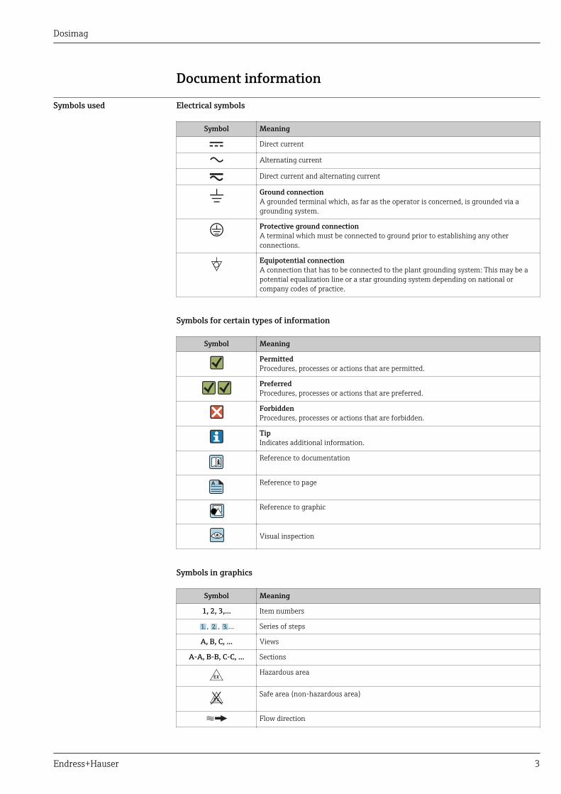
Symbols used Electrical symbols
Symbol Meaning
Direct current
Alternating current
Direct current and alternating current
Ground connectionA grounded terminal which, as far as the operator is concerned, is grounded via agrounding system.
Protective ground connectionA terminal which must be connected to ground prior to establishing any otherconnections.
Equipotential connectionA connection that has to be connected to the plant grounding system: This may be apotential equalization line or a star grounding system depending on national orcompany codes of practice.
Symbols for certain types of information
Symbol Meaning
PermittedProcedures, processes or actions that are permitted.
PreferredProcedures, processes or actions that are preferred.
ForbiddenProcedures, processes or actions that are forbidden.
TipIndicates additional information.
Reference to documentation
A Reference to page
Reference to graphic
Visual inspection
Symbols in graphics
Symbol Meaning
1, 2, 3,... Item numbers
1. , 2. , 3.… Series of steps
A, B, C, ... Views
A-A, B-B, C-C, ... Sections
-Hazardous area
. Safe area (non-hazardous area)
Flow direction
Dosimag
4 Endress+Hauser
Function and system design
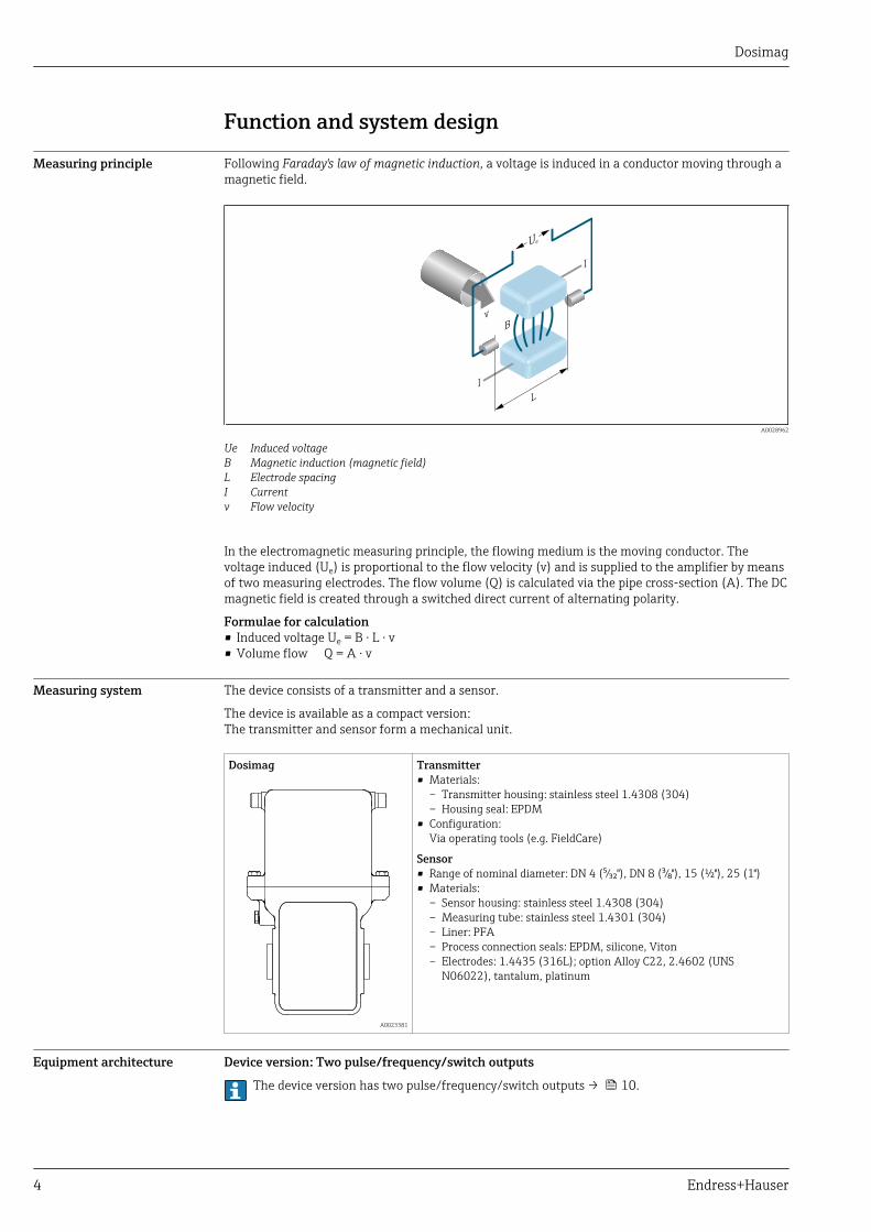
Measuring principle Following Faraday's law of magnetic induction, a voltage is induced in a conductor moving through amagnetic field.
Ue
L
B
I
I
v
A0028962
Ue Induced voltageB Magnetic induction (magnetic field)L Electrode spacingI Currentv Flow velocity
In the electromagnetic measuring principle, the flowing medium is the moving conductor. Thevoltage induced (Ue) is proportional to the flow velocity (v) and is supplied to the amplifier by meansof two measuring electrodes. The flow volume (Q) is calculated via the pipe cross-section (A). The DCmagnetic field is created through a switched direct current of alternating polarity.
Formulae for calculation• Induced voltage Ue = B · L · v• Volume flow Q = A · v
Measuring system The device consists of a transmitter and a sensor.
The device is available as a compact version:The transmitter and sensor form a mechanical unit.
Dosimag
A0023381
Transmitter• Materials:
– Transmitter housing: stainless steel 1.4308 (304)– Housing seal: EPDM
• Configuration:Via operating tools (e.g. FieldCare)
Sensor• Range of nominal diameter: DN 4 (⁵⁄₃₂"), DN 8 (³⁄₈"), 15 (½"), 25 (1")• Materials:
– Sensor housing: stainless steel 1.4308 (304)– Measuring tube: stainless steel 1.4301 (304)– Liner: PFA– Process connection seals: EPDM, silicone, Viton– Electrodes: 1.4435 (316L); option Alloy C22, 2.4602 (UNS
N06022), tantalum, platinum
Equipment architecture Device version: Two pulse/frequency/switch outputs
The device version has two pulse/frequency/switch outputs → 10.
Dosimag
Endress+Hauser 5
1
2
3
4
A0027057
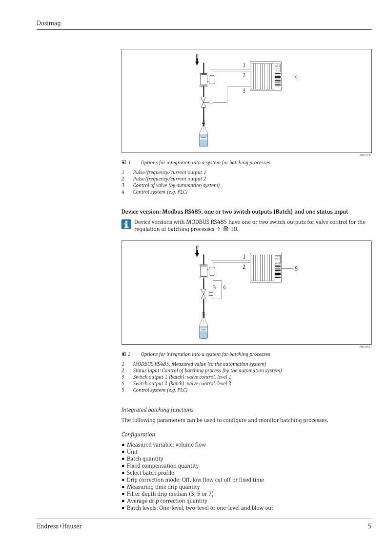
1 Options for integration into a system for batching processes
1 Pulse/frequency/current output 12 Pulse/frequency/current output 23 Control of valve (by automation system)4 Control system (e.g. PLC)
Device version: Modbus RS485, one or two switch outputs (Batch) and one status input
Device versions with MODBUS RS485 have one or two switch outputs for valve control for theregulation of batching processes → 10.
1
2
3
5
4
A0026621
2 Options for integration into a system for batching processes
1 MODBUS RS485: Measured value (to the automation system)2 Status input: Control of batching process (by the automation system)3 Switch output 1 (batch): valve control, level 14 Switch output 2 (batch): valve control, level 25 Control system (e.g. PLC)
Integrated batching functions
The following parameters can be used to configure and monitor batching processes.
Configuration
• Measured variable: volume flow• Unit• Batch quantity• Fixed compensation quantity• Select batch profile• Drip correction mode: Off, low flow cut off or fixed time• Measuring time drip quantity• Filter depth drip median (3, 5 or 7)• Average drip correction quantity• Batch levels: One-level, two-level or one-level and blow out
Dosimag
6 Endress+Hauser
• Start and stop level 2• Blow out delay and duration• Maximum batch time• Maximum flow• Disable time pressure shock suppression
Display
• Total amount measured from last batching process (incl. drip quantity)• Duration of last batching process (incl. measurement of drip quantity)• Switch-off time: From time of switch-off to when measurement of the drip quantity is complete• Current drip correction quantity (drip correction quantity for next batching process)• Sum of all batching processes measured• Number of batching processes
The batching process (start batch, stop batch etc.) is controlled by the automation system viathe status input or the Modbus RS485 .
Safety IT security
We only provide a warranty if the device is installed and used as described in the OperatingInstructions. The device is equipped with security mechanisms to protect it against any inadvertentchanges to the device settings.
IT security measures in line with operators' security standards and designed to provide additionalprotection for the device and device data transfer must be implemented by the operators themselves.
Input
Measured variable Direct measured variables
Volume flow (proportional to induced voltage)
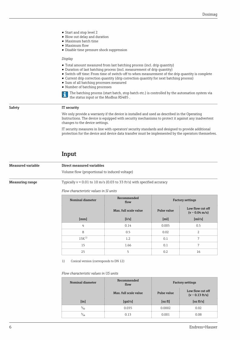
Measuring range Typically v = 0.01 to 10 m/s (0.03 to 33 ft/s) with specified accuracy
Flow characteristic values in SI units
Nominal diameter Recommendedflow Factory settings
Max. full scale value Pulse value Low flow cut off(v ~ 0.04 m/s)
[mm] [l/s] [ml] [ml/s]
4 0.14 0.005 0.5
8 0.5 0.02 2
15K 1) 1.2 0.1 7
15 1.66 0.1 7
25 5 0.2 16
1) Conical version (corresponds to DN 12)
Flow characteristic values in US units
Nominal diameter Recommendedflow Factory settings
Max. full scale value Pulse value Low flow cut off(v ~ 0.13 ft/s)
[in] [gal/s] [oz fl] [oz fl/s]
⁵⁄₃₂ 0.035 0.0002 0.02
⁵⁄₁₆ 0.13 0.001 0.08

Dosimag
Endress+Hauser 7
Nominal diameter Recommendedflow Factory settings
Max. full scale value Pulse value Low flow cut off(v ~ 0.13 ft/s)
[in] [gal/s] [oz fl] [oz fl/s]
½K 1) 0.32 0.004 0.25
½ 0.44 0.004 0.25
1 1.33 0.007 0.53
1) Conical version (corresponds to DN 12)
To calculate the measuring range, use the Applicator sizing tool → 42
Recommended measuring range
"Flow limit" section → 26
Operable flow range Over 1000 : 1
Input signal Available only for device versions using the Modbus RS485 communication method → 10.
Status input
The batching process is controlled by the automation system via the device's status input.
Maximum input values • DC 30 V• 6 mA
Response time Adjustable: 10 to 200 ms
Input signal level • Low level: 0 to 1.5 V• High level: 3 to 30 V
Assignable functions • Off• Start batching process• Start and stop batching process• Reset totalizers 1-3 separately• Reset all totalizers• Flow override
Output
Output signal Pulse/frequency/switch output
Function Can be set to:• Pulse
Quantity-proportional pulse with pulse width to be configured.• Automatic pulse
Quantity-proportional pulse with on/off ratio of 1:1• Frequency
Flow-proportional frequency output with on/off ratio of 1:1• Switch
Contact for displaying a status
Channel 2 Redundant output of pulse output: 0°, 90° or 180°
Version Passive, open emitter
Maximum input values • DC 30 V• 25 mA

Dosimag
8 Endress+Hauser
Voltage drop At 25 mA: ≤ DC 2 V
Pulse output
Pulse width Adjustable: 0.05 to 3.75 ms
Maximum pulse rate 10 000 Impulse/s
Pulse value Adjustable
Assignable measuredvariables
Volume flow
Frequency output
Output frequency Adjustable: 0 to 10 000 Hz
Damping Adjustable: 0 to 999.9 s
Pulse/pause ratio 1:1
Assignable measuredvariables
Volume flow
Switch output
Switching behavior Binary, conductive or non-conductive
Number of switchingcycles
Unlimited
Assignable functions • Off• On• Diagnostic behavior
– Alarm– Alarm and warning– Warning
• Limit value:– Off– Volume flow– Flow velocity
• StatusLow flow cut off
Modbus RS485
Physical interface In accordance with EIA/TIA-485-A standard
Switch output (batch: valve control)
• Only available for device version with Modbus RS485 → 10.• Depending on the device version, the device has one or two switch outputs.
Switch output
Version Active, open emitter
Maximum input values • DC 30 V• 500 mA
Switching behavior Binary, conductive or non-conductive
Number of switchingcycles
Unlimited
Assignable functions • Open• Closed• Batching
Signal on alarm Depending on the interface, failure information is displayed as follows:
Dosimag
Endress+Hauser 9
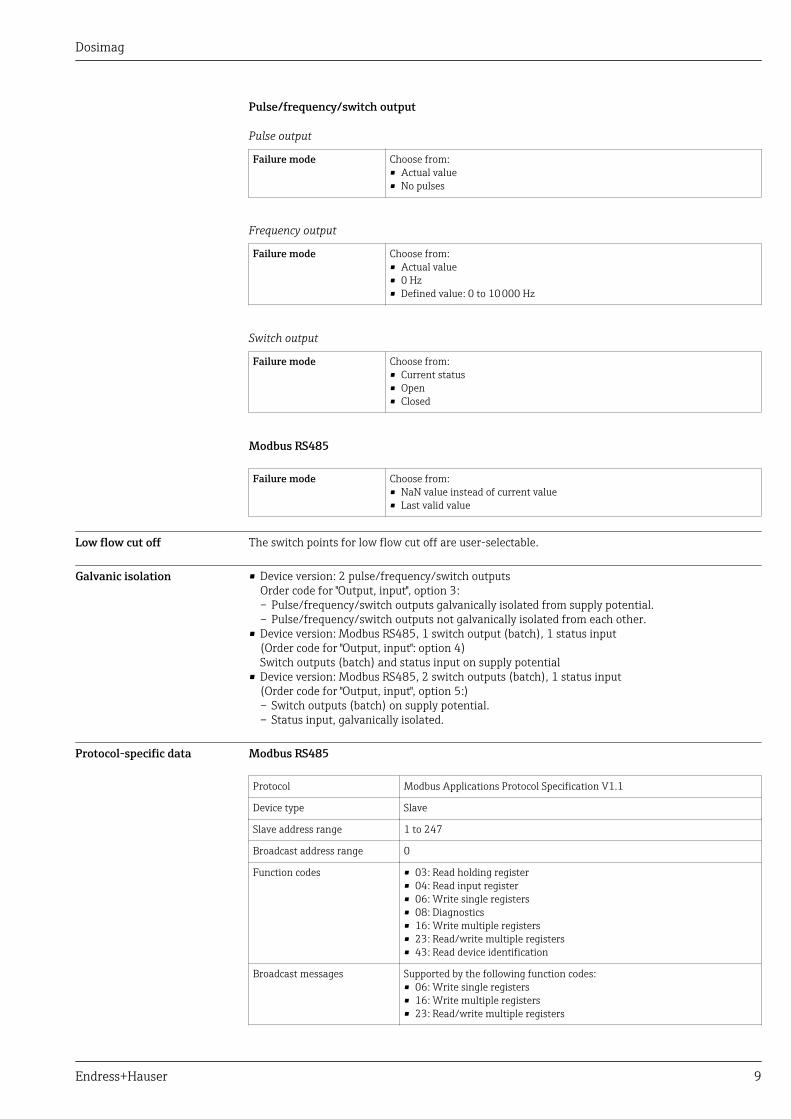
Pulse/frequency/switch output
Pulse output
Failure mode Choose from:• Actual value• No pulses
Frequency output
Failure mode Choose from:• Actual value• 0 Hz• Defined value: 0 to 10 000 Hz
Switch output
Failure mode Choose from:• Current status• Open• Closed
Modbus RS485
Failure mode Choose from:• NaN value instead of current value• Last valid value
Low flow cut off The switch points for low flow cut off are user-selectable.
Galvanic isolation • Device version: 2 pulse/frequency/switch outputsOrder code for "Output, input", option 3:– Pulse/frequency/switch outputs galvanically isolated from supply potential.– Pulse/frequency/switch outputs not galvanically isolated from each other.
• Device version: Modbus RS485, 1 switch output (batch), 1 status input(Order code for "Output, input": option 4)Switch outputs (batch) and status input on supply potential
• Device version: Modbus RS485, 2 switch outputs (batch), 1 status input(Order code for "Output, input", option 5:)– Switch outputs (batch) on supply potential.– Status input, galvanically isolated.
Protocol-specific data Modbus RS485
Protocol Modbus Applications Protocol Specification V1.1
Device type Slave
Slave address range 1 to 247
Broadcast address range 0
Function codes • 03: Read holding register• 04: Read input register• 06: Write single registers• 08: Diagnostics• 16: Write multiple registers• 23: Read/write multiple registers• 43: Read device identification
Broadcast messages Supported by the following function codes:• 06: Write single registers• 16: Write multiple registers• 23: Read/write multiple registers

Dosimag
10 Endress+Hauser
Supported baud rate • 1 200 BAUD• 2 400 BAUD• 4 800 BAUD• 9 600 BAUD• 19 200 BAUD• 38 400 BAUD• 57 600 BAUD• 115 200 BAUD
Data transfer mode • ASCII• RTU
Data access Each device parameter can be accessed via Modbus RS485.
For Modbus register information → 43
Power supply
Terminal assignment Connection is solely by means of device plug:
There are different device versions available:
Order code for "Output, input": Device plug
Option 3: 2 pulse/frequency/switch outputs 1) → 11
Option 4: Modbus RS485, 1 switch output (batch), 1 status input → 12
Option 5: Modbus RS485, 2 switch outputs (batch), 1 status input → 13
Option 6: Modbus RS485 (custody transfer mode) → 15
1) Can also be used for custody transfer mode.
Dosimag
Endress+Hauser 11
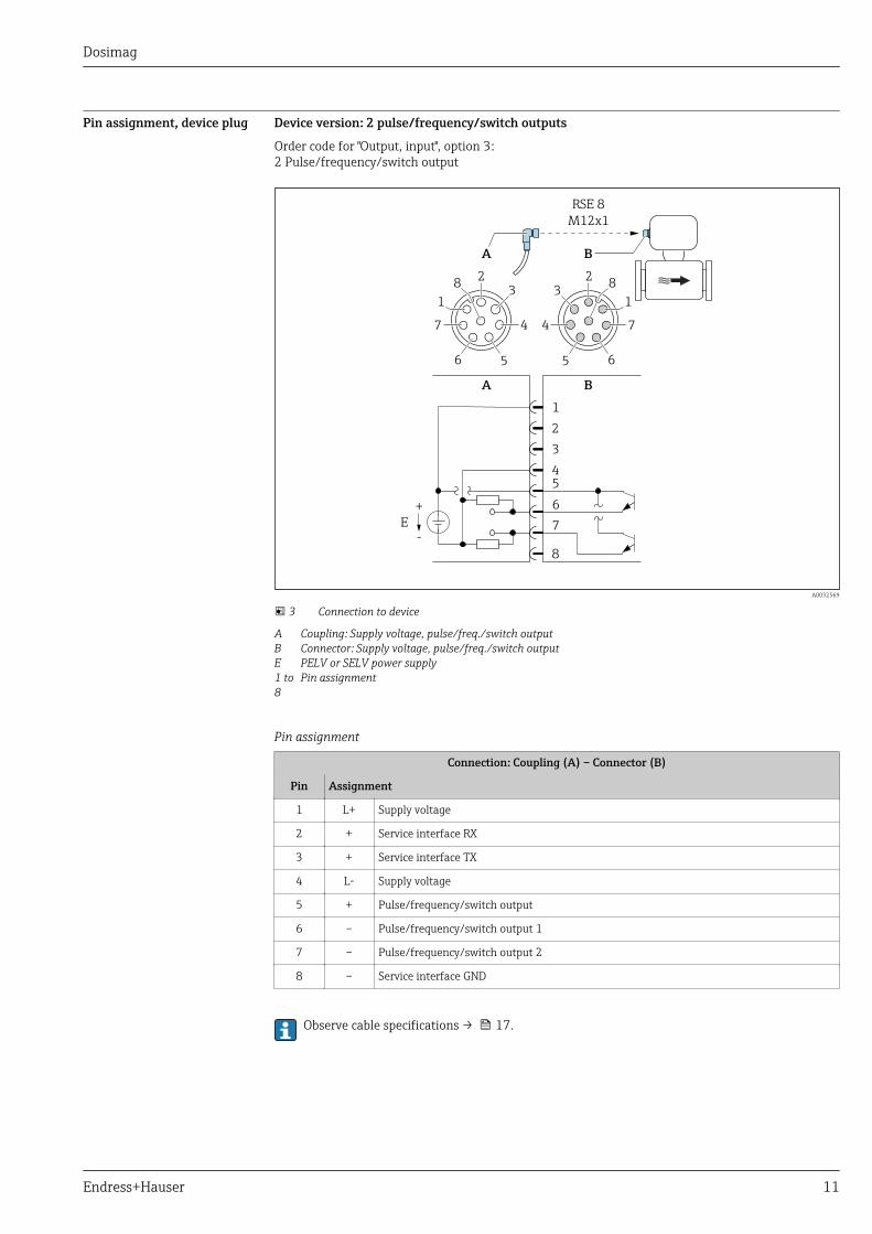
Pin assignment, device plug Device version: 2 pulse/frequency/switch outputs
Order code for "Output, input", option 3:2 Pulse/frequency/switch output
BA
RSE 8
M12x1
8
A B
1
2
3
4
5
6
7
+
-
E
7
2
4
6
13
5
8
7
2
4
6
13
5
8
A0032569
3 Connection to device
A Coupling: Supply voltage, pulse/freq./switch outputB Connector: Supply voltage, pulse/freq./switch outputE PELV or SELV power supply1 to8
Pin assignment
Pin assignment
Connection: Coupling (A) – Connector (B)
Pin Assignment
1 L+ Supply voltage
2 + Service interface RX
3 + Service interface TX
4 L- Supply voltage
5 + Pulse/frequency/switch output
6 – Pulse/frequency/switch output 1
7 – Pulse/frequency/switch output 2
8 – Service interface GND
Observe cable specifications → 17.
Dosimag
12 Endress+Hauser
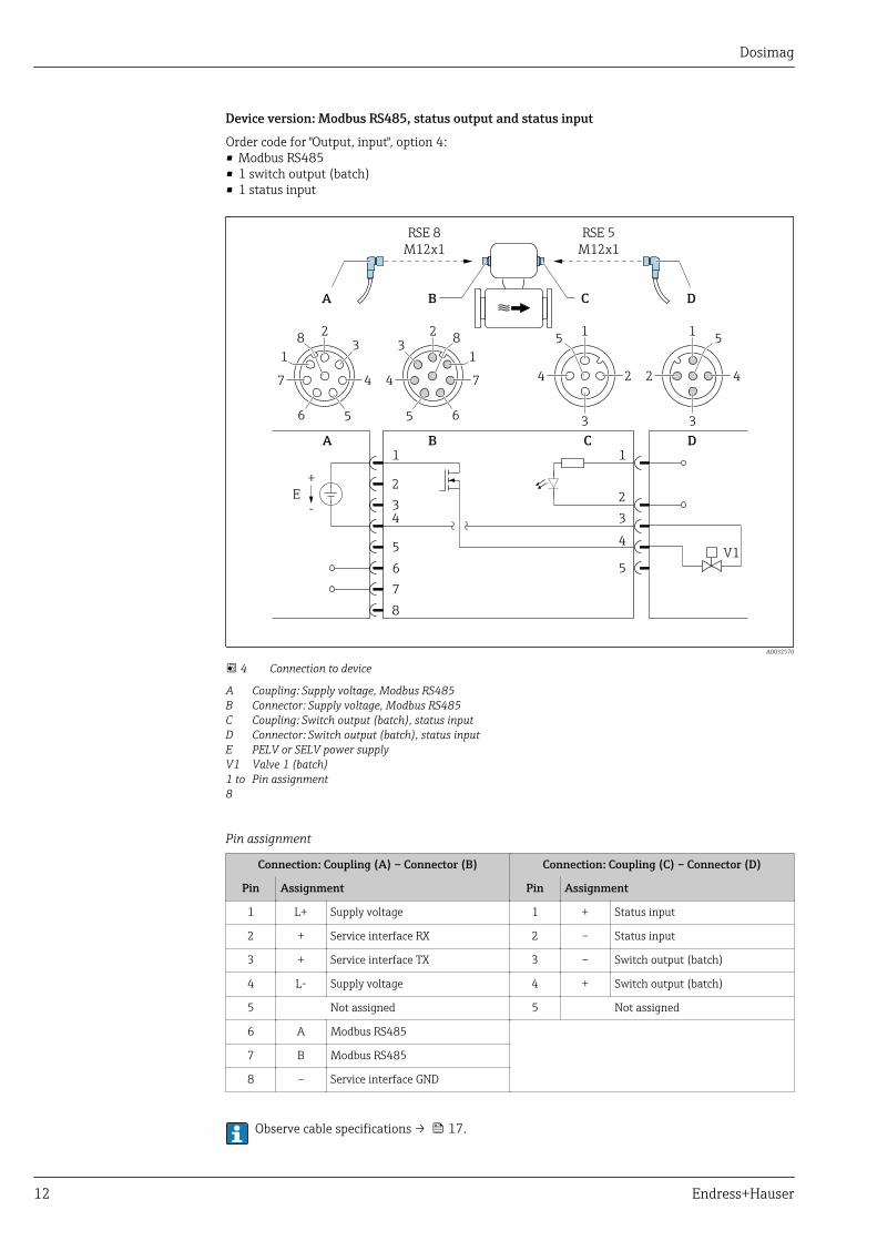
Device version: Modbus RS485, status output and status input
Order code for "Output, input", option 4:• Modbus RS485• 1 switch output (batch)• 1 status input
BA DC
RSE 5
M12x1
RSE 8
M12x1
C
8
A DB
1
2
3
4
5
6
7
2
3
1
5
E
4
V1
+
-
7
2
4
6
13
5
8
7
2
4
6
13
5
81
2 4
3
51
24
3
5
A0032570
4 Connection to device
A Coupling: Supply voltage, Modbus RS485B Connector: Supply voltage, Modbus RS485C Coupling: Switch output (batch), status inputD Connector: Switch output (batch), status inputE PELV or SELV power supplyV1 Valve 1 (batch)1 to8
Pin assignment
Pin assignment
Connection: Coupling (A) – Connector (B) Connection: Coupling (C) – Connector (D)
Pin Assignment Pin Assignment
1 L+ Supply voltage 1 + Status input
2 + Service interface RX 2 – Status input
3 + Service interface TX 3 – Switch output (batch)
4 L- Supply voltage 4 + Switch output (batch)
5 Not assigned 5 Not assigned
6 A Modbus RS485
7 B Modbus RS485
8 – Service interface GND
Observe cable specifications → 17.
Dosimag
Endress+Hauser 13
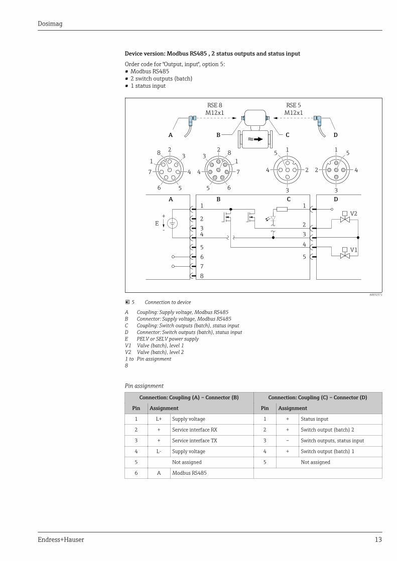
Device version: Modbus RS485 , 2 status outputs and status input
Order code for "Output, input", option 5:• Modbus RS485• 2 switch outputs (batch)• 1 status input
C
1
2
3
4
5
6
7
8
2
3
1
5
A
4
D
V2
V1
B
BA DC
RSE 5
M12x1
RSE 8
M12x1
E
+
-
7
2
4
6
13
5
8
7
2
4
6
13
5
81
2 4
3
51
24
3
5
A0032571
5 Connection to device
A Coupling: Supply voltage, Modbus RS485B Connector: Supply voltage, Modbus RS485C Coupling: Switch outputs (batch), status inputD Connector: Switch outputs (batch), status inputE PELV or SELV power supplyV1 Valve (batch), level 1V2 Valve (batch), level 21 to8
Pin assignment
Pin assignment
Connection: Coupling (A) – Connector (B) Connection: Coupling (C) – Connector (D)
Pin Assignment Pin Assignment
1 L+ Supply voltage 1 + Status input
2 + Service interface RX 2 + Switch output (batch) 2
3 + Service interface TX 3 – Switch outputs, status input
4 L- Supply voltage 4 + Switch output (batch) 1
5 Not assigned 5 Not assigned
6 A Modbus RS485

Dosimag
14 Endress+Hauser
Connection: Coupling (A) – Connector (B) Connection: Coupling (C) – Connector (D)
Pin Assignment Pin Assignment
7 B Modbus RS485
8 – Service interface GND
Observe cable specifications → 17.

Dosimag
Endress+Hauser 15
Device version: Modbus RS485 (custody transfer mode)
Order code for "Output, input", option 6 (device version for custody transfer mode):Modbus RS485
C
1
2
3
4
5
6
7
8
A DB
BA DC
RSE 8
M12x1
E
+
-
7
2
4
6
13
5
8
7
2
4
6
13
5
81
24
3
5
A0032572
6 Connection to device
A Coupling: Supply voltage, Modbus RS485B Connector: Supply voltage, Modbus RS485C Coupling at deviceD Connector: Dongle (hardware write protection for custody transfer mode)E PELV or SELV power supply
Pin assignment
Connection: Coupling (A) – Connector (B) Connection: Coupling (C) – Connector (D)
Pin Assignment Pin Assignment
1 L+ Supply voltage 1 NC
2 + Service interface RX 2 NC
3 + Service interface TX 3 NC
4 L- Supply voltage 4 +
5 Not assigned 5 -
6 A Modbus RS485
7 B Modbus RS485
8 – Service interface GND
Observe cable specifications → 17.
Supply voltage DC 24 V (nominal voltage: DC 20 to 30 V)
• The power unit must be tested to ensure that it meets safety requirements (e.g. PELV, SELV).• The supply voltage must not exceed a maximum short-circuit current of 50 A.
Dosimag
16 Endress+Hauser
Power consumption 4.5 W
Current consumptionOrder code for "Output, input": Maximum
Power consumption
Option 3: 2 pulse/frequency/switch outputs 225 mA
Option 4: Modbus RS485, 1 switch output (batch), 1 status input 225 mA + 500 mA 1)
Option 5: Modbus RS485, 2 switch outputs (batch), 1 status input 225 mA + 1 000 mA 1)
Option 6: Modbus RS485 (custody transfer mode) 225 mA
1) Additional 500 mA per switch output (batch) used.
Switch-on current: max. 1 A (< 8 ms)
Power supply failure • Totalizers stop at the last value measured.• Error messages (incl. total operated hours) are stored.
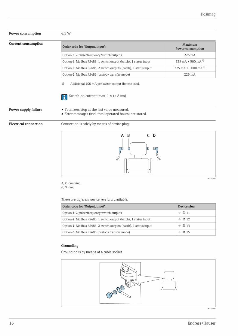
Electrical connection Connection is solely by means of device plug:
BA DC
A0032534
A, C CouplingB, D Plug
There are different device versions available:
Order code for "Output, input": Device plug
Option 3: 2 pulse/frequency/switch outputs → 11
Option 4: Modbus RS485, 1 switch output (batch), 1 status input → 12
Option 5: Modbus RS485, 2 switch outputs (batch), 1 status input → 13
Option 6: Modbus RS485 (custody transfer mode) → 15
Grounding
Grounding is by means of a cable socket.
A0003838
Dosimag
Endress+Hauser 17
Potential equalization Requirements
No potential matching is needed for grounded steel lines.
For devices intended for use in hazardous locations, please observe the guidelines in the Exdocumentation (XA).
Cable specification Permitted temperature range
• –40 °C (–40 °F) to +80 °C (+176 °F)• Minimum requirement: cable temperature range ≥ ambient temperature +20 K
Signal cable
Cables are not included in the scope of delivery; they can be ordered as an accessory → 41.
Pulse/frequency/switch output
Standard installation cable is sufficient.
Status input and switch output (batch)
Standard installation cable is sufficient.
Modbus RS485
• The electrical connection of the shield to the device housing must be properly implemented(e.g. using a knurled nut).
• Please note the following with regard to cable loading:– Voltage drop due to the cable length and cable type.– Valve performance.
Total length of cable in the Modbus network ≤ 50 m
Use a shielded cable.
Example:Terminated device connector with cable: Lumberg RKWTH 8-299/10
Total length of cable in the Modbus network > 50 m
Use shielded twisted pair cable for RS485 applications.
Example:• Cable: Belden item no. 9842 (for 4-wire version, the same cable can be used for the power supply)• Terminated device plug: Lumberg RKCS 8/9 (shieldable version)
RSE8 to RSE5 adapter
This adapter is not included in the scope of delivery. It is essential for custody transfer mode.

Dosimag
18 Endress+Hauser
A BC
BA
RSE 5
M12x1
RSE 8
M12x1
E
+
-
7
2
4
6
13
5
8
7
2
4
6
13
5
82
3 1
4
52
31
4
5
PE
1
4
5
6
7
C
3
2
1
4
5
A0032840
7 Connection to device
A CouplingB PlugC RSE8 to RSE5 adapter cableE PELV or SELV power supply
Pin assignment
Pin Assignment
1 + Supply voltage
2 + Pulse/frequency/switch output
3 - Pulse/frequency/switch output
4 – Supply voltage
5 - Pulse/frequency/switch output
Performance characteristics
Reference operatingconditions
In accordance with DIN EN 29104• Medium temperature: +28 ± 2 °C (+82 ± 4 °F)• Ambient temperature: +22 ± 2 °C (+72 ± 4 °F)• Warm-up period:30 minInstallation• Inlet run > 10 × DN• Outlet run > 5 × DN• Sensor and transmitter grounded.• The sensor is centered in the pipe.
To calculate the measuring range, use the Applicator sizing tool → 42

Dosimag
Endress+Hauser 19
Maximum measured error Error limits under reference operating conditions
o.r. = of reading
Volume flow• ±0.25 % o.r. ± 1 to 4 m/s (3.3 to 13 ft/s) or• ±0.5 % o.r. ± 1 mm/s (0.04 in/s) or• ±5 % o.r.
Fluctuations in the supply voltage do not have any effect within the specified range.
Accuracy of outputs
In the case of analog outputs, the output accuracy must also be considered for the measurederror, in contrast, this need not be considered in the case of fieldbus outputs (Modbus RS485).
The outputs have the following base accuracy specifications.
Pulse/frequency output
o.r. = of reading
Accuracy Max. ±50 ppm o.r. (across the entire ambient temperature range)
Repeatability o.r. = of reading
DN 25 (500 ml/s), DN 15 (200 ml/s), DN 8 (50 ml/s), DN 4 (10 ml/s); 400 μS/cm
Batch time ta [s] Relative standard deviation in relation to the batched volume [%]
1.5 s < ta < 3 s 0.4
3 s < ta < 5 s 0.2
5 s < ta 0.1
DN 15K (200 ml/s); 400 μS/cm
Batch time ta [s] Relative standard deviation in relation to the batched volume [%]
1.5 s < ta < 3 s 0.25
3 s < ta < 5 s 0.12
5 s < ta 0.08
Influence of ambienttemperature
Pulse/frequency output
Temperature coefficient No additional effect. Included in accuracy.
InstallationNo special measures such as supports etc. are necessary. External forces are absorbed by theconstruction of the device.
Dosimag
20 Endress+Hauser
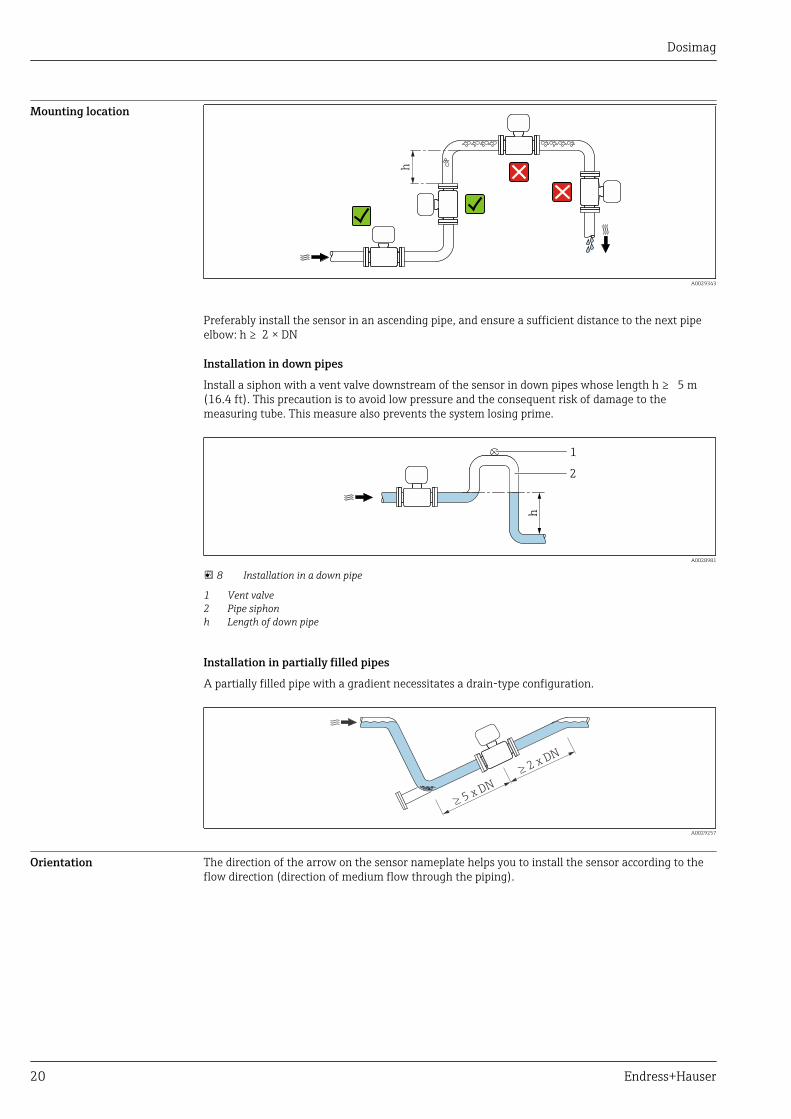
Mounting location
h
A0029343
Preferably install the sensor in an ascending pipe, and ensure a sufficient distance to the next pipeelbow: h ≥ 2 × DN
Installation in down pipes
Install a siphon with a vent valve downstream of the sensor in down pipes whose length h ≥ 5 m(16.4 ft). This precaution is to avoid low pressure and the consequent risk of damage to themeasuring tube. This measure also prevents the system losing prime.
h
2
1
A0028981
8 Installation in a down pipe
1 Vent valve2 Pipe siphonh Length of down pipe
Installation in partially filled pipes
A partially filled pipe with a gradient necessitates a drain-type configuration.
2 x DN
³
5 x DN
³
A0029257
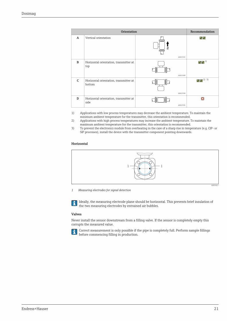
Orientation The direction of the arrow on the sensor nameplate helps you to install the sensor according to theflow direction (direction of medium flow through the piping).
Dosimag
Endress+Hauser 21
Orientation Recommendation
A Vertical orientation
A0015591
B Horizontal orientation, transmitter attop
A0015589
1)
C Horizontal orientation, transmitter atbottom
A0015590
2) 3)
D Horizontal orientation, transmitter atside
A0015592
1) Applications with low process temperatures may decrease the ambient temperature. To maintain theminimum ambient temperature for the transmitter, this orientation is recommended.
2) Applications with high process temperatures may increase the ambient temperature. To maintain themaximum ambient temperature for the transmitter, this orientation is recommended.
3) To prevent the electronics module from overheating in the case of a sharp rise in temperature (e.g. CIP- orSIP processes), install the device with the transmitter component pointing downwards.
Horizontal
11
A0025817
1 Measuring electrodes for signal detection
Ideally, the measuring electrode plane should be horizontal. This prevents brief insulation ofthe two measuring electrodes by entrained air bubbles.
Valves
Never install the sensor downstream from a filling valve. If the sensor is completely empty thiscorrupts the measured value.
Correct measurement is only possible if the pipe is completely full. Perform sample fillingsbefore commencing filling in production.

Dosimag
22 Endress+Hauser
1
2
2
1
3 3
A0003768
1 Measuring device2 Filling valve3 Container
Filling systems
The pipe system must be completely full to ensure optimum measurement.
1 2 1 2
1
2
3 3 3
A0003795
9 Filling system
1 Measuring device2 Filling valve3 Container
Inlet and outlet runs If possible, install the sensor upstream from fittings such as valves, T-pieces or elbows.
Observe the following inlet and outlet runs to comply with accuracy specifications:
≥ 5 x DN ≥ 2 x DN
A0028997
Adapters Suitable adapters to DIN EN 545 (double-flange reducers) can be used to install the sensor in larger-diameter pipes. The resultant increase in the rate of flow improves measuring accuracy with veryslow-moving fluids.
Dosimag
Endress+Hauser 23
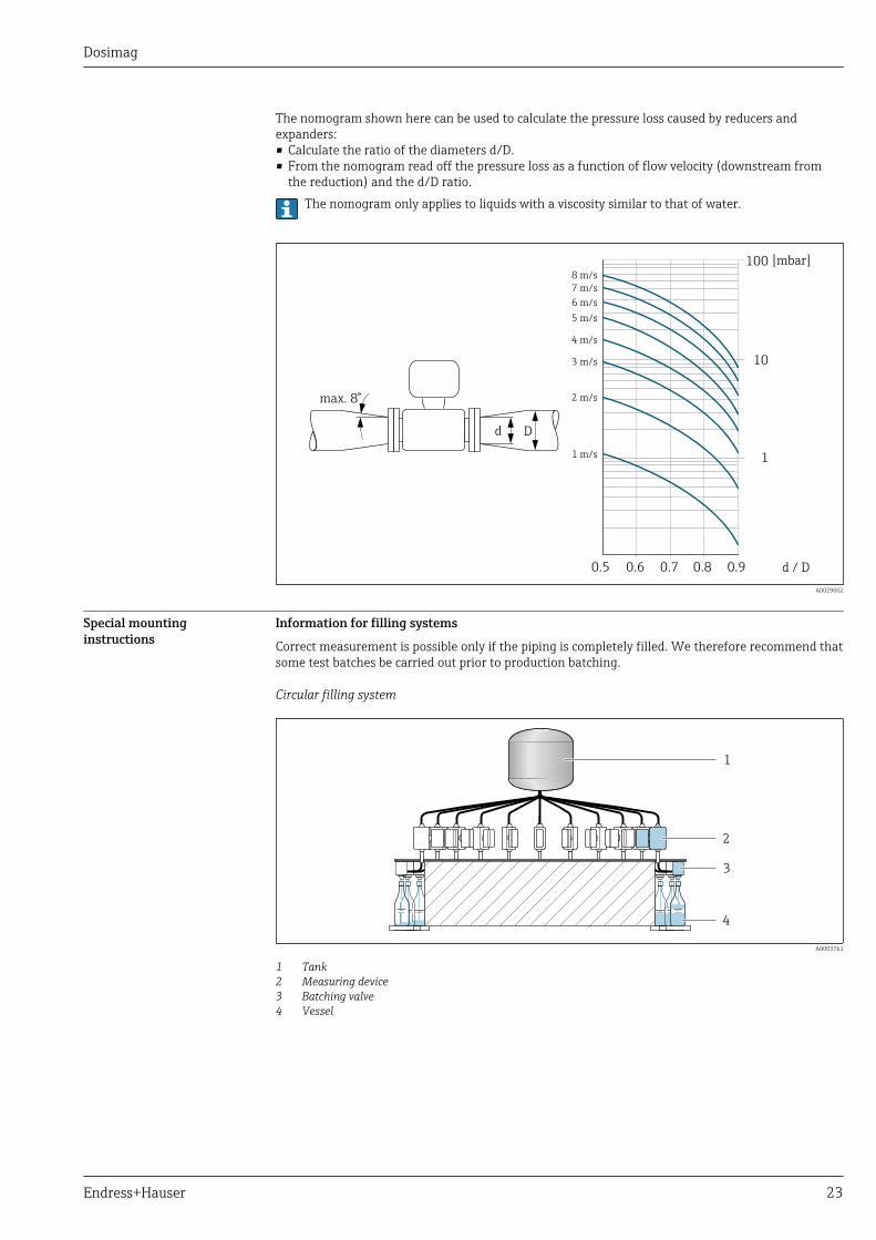
The nomogram shown here can be used to calculate the pressure loss caused by reducers andexpanders:• Calculate the ratio of the diameters d/D.• From the nomogram read off the pressure loss as a function of flow velocity (downstream from
the reduction) and the d/D ratio.The nomogram only applies to liquids with a viscosity similar to that of water.
100
10
0.5 d / D
[mbar]
0.6 0.7 0.8 0.9
1 m/s
2 m/s
3 m/s
4 m/s
5 m/s
6 m/s
7 m/s
8 m/s
1
Dd
max. 8°
A0029002
Special mountinginstructions
Information for filling systems
Correct measurement is possible only if the piping is completely filled. We therefore recommend thatsome test batches be carried out prior to production batching.
Circular filling system
4
3
2
1
A0003761
1 Tank2 Measuring device3 Batching valve4 Vessel

Dosimag
24 Endress+Hauser
Linear filling system
1
3
4
2
A0003762
1 Tank2 Measuring device3 Batching valve4 Vessel
Environment
Ambient temperature range Transmitter –40 to +60 °C (–40 to +140 °F)
Sensor –40 to +60 °C (–40 to +140 °F)
Temperature tables
The following interdependencies between the permitted ambient and fluid temperatures apply whenoperating the device in hazardous areas:
Ex nA
SI units
T5[100 °C]
T4[135 °C]
T3[200 °C]
T2[300 °C]
T1[450 °C]
Ambient temperature Ta 60 50 45 45 45
Maximum medium temperature Tm 70 105 130 130 130
US units
T5[212 °F]
T4[275 °F]
T3[392 °F]
T2[572 °F]
T1[842 °F]
Ambient temperature Ta 140 122 113 113 113
Maximum medium temperature Tm 158 221 266 266 266
The minimum temperature of the medium is –20 °C (–4 °F).
The minimum ambient temperature is –40 °C (–40 °F).
Storage temperature The storage temperature corresponds to the ambient temperature range of the transmitter andsensor.→ 24
Dosimag
Endress+Hauser 25
• Protect the measuring device against direct sunlight during storage in order to avoid unacceptablyhigh surface temperatures.
• Select a storage location where moisture cannot collect in the measuring device as fungus orbacteria infestation can damage the liner.
• If protection caps or protective covers are mounted these should never be removed beforeinstalling the measuring device.
Degree of protection As standard: IP67, type 4X enclosure
Shock resistance Acceleration up to 2 g based on IEC 60068-2-6
Vibration resistance Acceleration up to 2 g based on IEC 60068-2-6
Interior cleaning • Cleaning in place (CIP)• Sterilization in place (SIP)
Observe the maximum medium temperatures → 25
Electromagneticcompatibility (EMC)
According to IEC/EN 61326For details, refer to the Declaration of Conformity.
Process
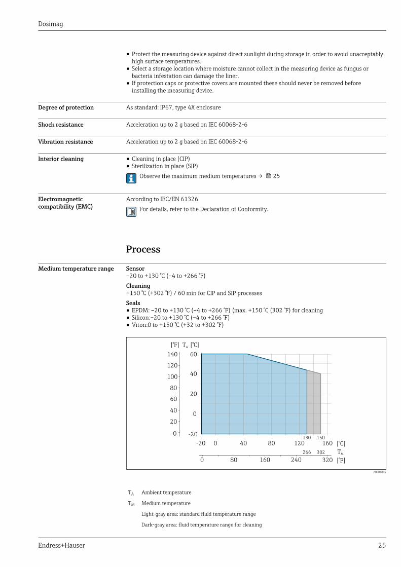
Medium temperature range Sensor–20 to +130 °C (–4 to +266 °F)Cleaning+150 °C (+302 °F) / 60 min for CIP and SIP processesSeals• EPDM: –20 to +130 °C (–4 to +266 °F) (max. +150 °C (302 °F) for cleaning• Silicon:–20 to +130 °C (–4 to +266 °F)• Viton:0 to +150 °C (+32 to +302 °F)
0
-20
20
40
60
[°F] T [°C]A
140
120
80
60
100
0
40
20
0-20 40 80 120
80 160 240 3200
160
TM
130
266 302
150
[°F]
[°C]
A0004805
TA Ambient temperature
TM Medium temperature
Light-gray area: standard fluid temperature range
Dark-gray area: fluid temperature range for cleaning
Dosimag
26 Endress+Hauser
Conductivity • ≥ 5 μS/cm for liquids in general• ≥ 10 μS/cmfor demineralized water
Pressure-temperatureratings
Permitted process pressure: 16 bar (232 psi)
Process connection: Welded connection as per EN 10357 (DIN 11850), ODT/SMS;clamp L14 AM7
PN16
[bar]
-60 -40 -20 0 20 40 60 80 100120140160180 [°C]
0
5
15
10
20
25
[psi]
360 [°F]0-40 100 200 300
100
200
300
0
A0028940-EN
10 Process connection material: 1.4404 (316L) (with molded seal)
Pressure tightness Liner: PFA
Nominal diameter Limit values for absolute pressure in [mbar] ([psi]) for fluid temperatures:
[mm] [in] +25 °C (+77 °F) +150 °C (+302 °F)
4 to 25 ⁵⁄₃₂ to 1 > 1 mbar (0.402 inH2O) (0) > 1 mbar (0.402 inH2O) (0)
Flow limit The diameter of the pipe and the flow rate determine the nominal diameter of the sensor. Theoptimum flow velocity is between 2 to 3 m/s (6.56 to 9.84 ft/s). Also match the velocity of flow (v)to the physical properties of the fluid:• v < 2 m/s (6.56 ft/s): For abrasive media (e.g. cleaning agents)• v > 2 m/s (6.56 ft/s): For media that produce buildup (e.g. liquids containing oil and sugar)
A necessary increase in the flow velocity can be achieved by reducing the sensor nominaldiameter.For an overview of the full scale values for the measuring range, see the "Measuring range"section → 6
Pressure loss • For DN 8 (5/16"), DN 15 (½") and DN 25 (1") no pressure loss occurs if the sensor is installed in apipe with the same nominal diameter.
• Pressure losses for configurations incorporating adapters according to DIN EN 545 → 22
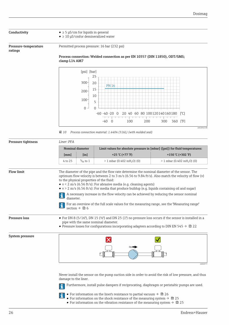
System pressure
A0028777
Never install the sensor on the pump suction side in order to avoid the risk of low pressure, and thusdamage to the liner.
Furthermore, install pulse dampers if reciprocating, diaphragm or peristaltic pumps are used.
• For information on the liner's resistance to partial vacuum → 26• For information on the shock resistance of the measuring system → 25• For information on the vibration resistance of the measuring system → 25
Dosimag
Endress+Hauser 27
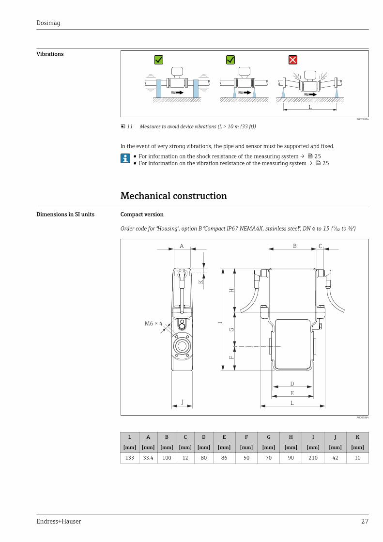
Vibrations
L
A0029004
11 Measures to avoid device vibrations (L > 10 m (33 ft))
In the event of very strong vibrations, the pipe and sensor must be supported and fixed.
• For information on the shock resistance of the measuring system → 25• For information on the vibration resistance of the measuring system → 25
Mechanical construction
Dimensions in SI units Compact version
Order code for "Housing", option B "Compact IP67 NEMA4X, stainless steel", DN 4 to 15 (⁵⁄₃₂ to ½")
L
B
D
E
H
I
J
M6 × 4
A C
GF
K
A0003864
L A B C D E F G H I J K
[mm] [mm] [mm] [mm] [mm] [mm] [mm] [mm] [mm] [mm] [mm] [mm]
133 33.4 100 12 80 86 50 70 90 210 42 10
Dosimag
28 Endress+Hauser
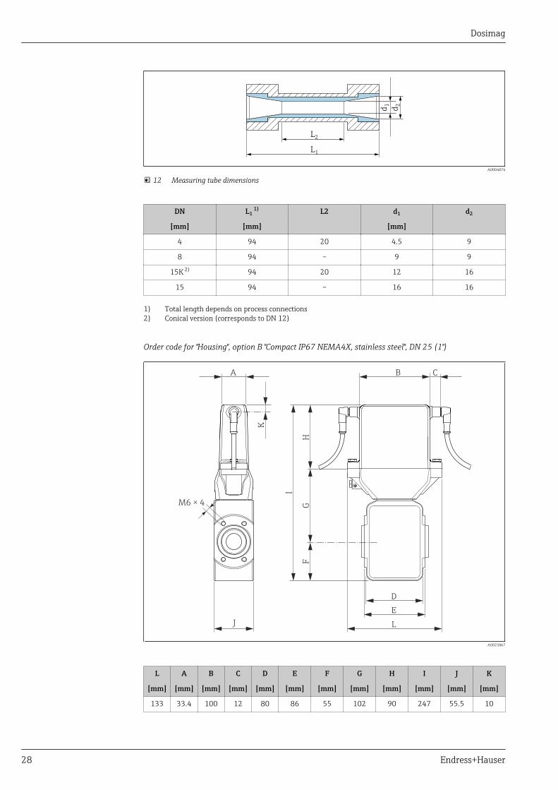
L2
L1
d1
d2
A0004874
12 Measuring tube dimensions
DN L1 1) L2 d1 d2
[mm] [mm] [mm]
4 94 20 4.5 9
8 94 – 9 9
15K 2) 94 20 12 16
15 94 – 16 16
1) Total length depends on process connections2) Conical version (corresponds to DN 12)
Order code for "Housing", option B "Compact IP67 NEMA4X, stainless steel", DN 25 (1")
L
B
D
E
H
I
J
M6 × 4
A C
GF
K
A0025867
L A B C D E F G H I J K
[mm] [mm] [mm] [mm] [mm] [mm] [mm] [mm] [mm] [mm] [mm] [mm]
133 33.4 100 12 80 86 55 102 90 247 55.5 10
Dosimag
Endress+Hauser 29
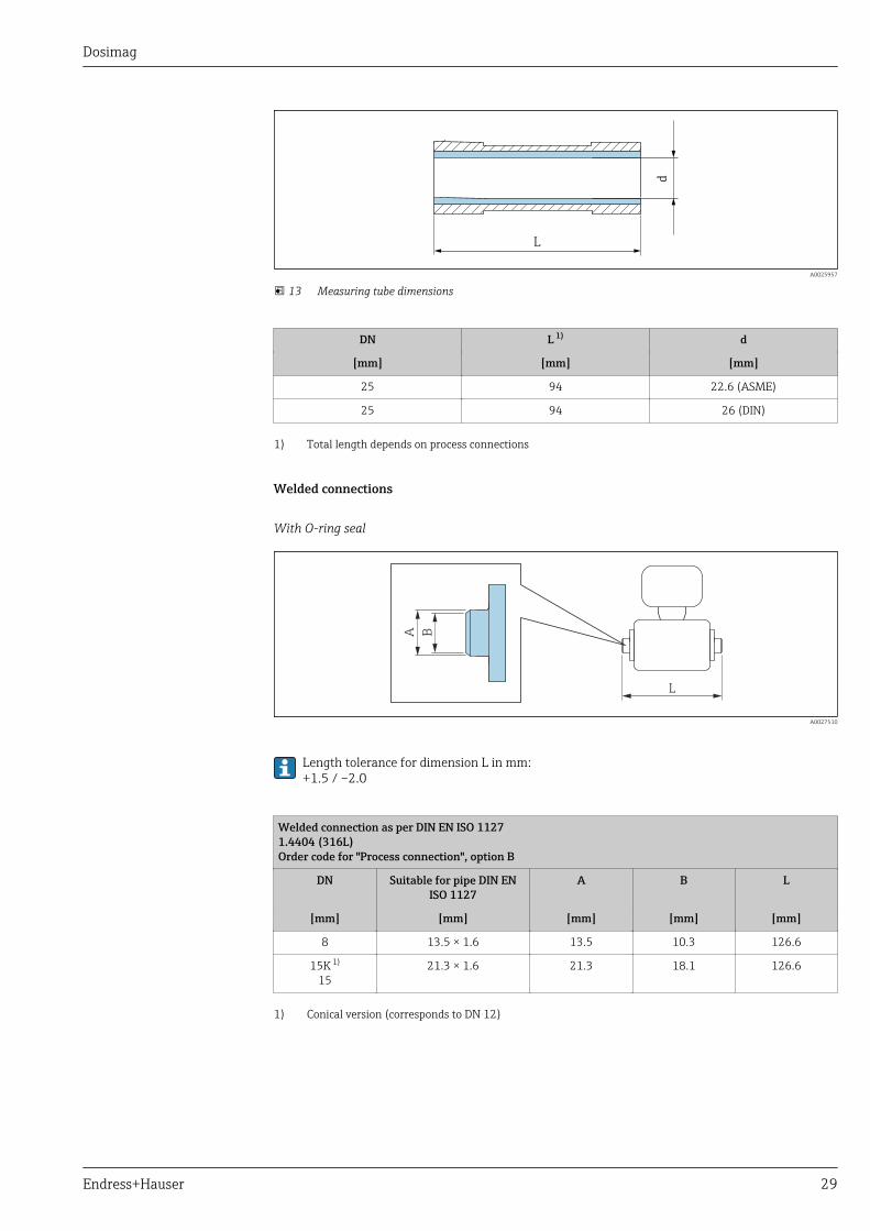
L
d
A0025957
13 Measuring tube dimensions
DN L 1) d
[mm] [mm] [mm]
25 94 22.6 (ASME)
25 94 26 (DIN)
1) Total length depends on process connections
Welded connections
With O-ring seal
L
A B
A0027510
Length tolerance for dimension L in mm:+1.5 / –2.0
Welded connection as per DIN EN ISO 11271.4404 (316L)Order code for "Process connection", option B
DN Suitable for pipe DIN ENISO 1127
A B L
[mm] [mm] [mm] [mm] [mm]
8 13.5 × 1.6 13.5 10.3 126.6
15K 1)
1521.3 × 1.6 21.3 18.1 126.6
1) Conical version (corresponds to DN 12)

Dosimag
30 Endress+Hauser
Welded connection as per ODT/SMS1.4404 (316L)Order code for "Process connection", option C
DN Suitable for pipe ODT/SMS A B L
[mm] [mm] [mm] [mm] [mm]
8 13.5 × 2.30 13.5 9 126.6
15K 1)
1521.3 × 2.65 21.3 16 126.6
1) Conical version (corresponds to DN 12)
With aseptic molded seal:
L
A B
A0027510
Length tolerance for dimension L in mm:+1.5 / –2.0
Welded connection EN 10357 (DIN 11850)1.4404 (316L): Order code for "Process connection", option U
DN sensor Suitable for pipeEN 10357
(DIN 11850)
A B L
[mm] [mm] [mm] [mm] [mm]
48 13 × 1.5 13 10 132
15K 1)
15 19 × 1.5 19 16 132
25 30 × 2 30 26 132.3
It is essential to take the internal diameters of the measuring tube and process connection (B) into accountwhen cleaning with pigs!
1) Conical version (corresponds to DN 12)
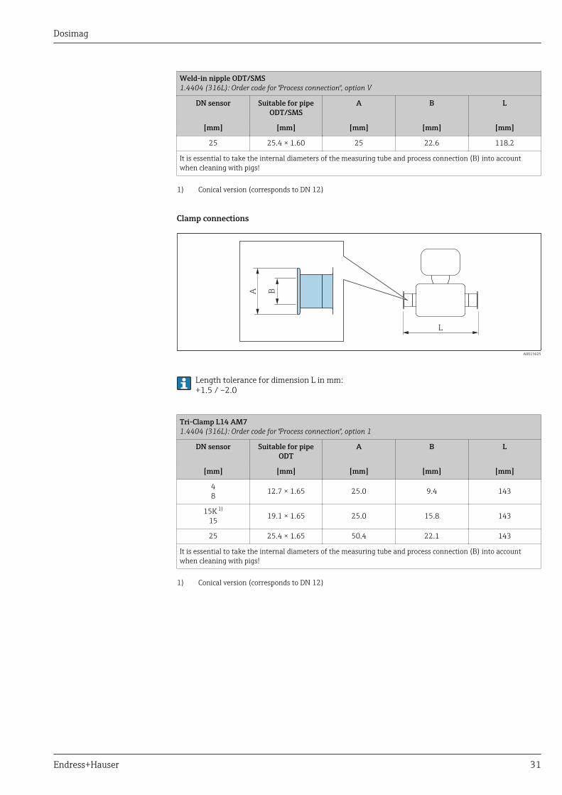
Weld-in nipple ODT/SMS1.4404 (316L): Order code for "Process connection", option V
DN sensor Suitable for pipeODT/SMS
A B L
[mm] [mm] [mm] [mm] [mm]
48 12.7 × 1.65 12 10 118.2
15K 1)
15 19.05 × 1.65 18 16 118.2
Dosimag
Endress+Hauser 31
Weld-in nipple ODT/SMS1.4404 (316L): Order code for "Process connection", option V
DN sensor Suitable for pipeODT/SMS
A B L
[mm] [mm] [mm] [mm] [mm]
25 25.4 × 1.60 25 22.6 118.2
It is essential to take the internal diameters of the measuring tube and process connection (B) into accountwhen cleaning with pigs!
1) Conical version (corresponds to DN 12)
Clamp connections
L
A B
A0015625
Length tolerance for dimension L in mm:+1.5 / –2.0
Tri-Clamp L14 AM71.4404 (316L): Order code for "Process connection", option 1
DN sensor Suitable for pipeODT
A B L
[mm] [mm] [mm] [mm] [mm]
48 12.7 × 1.65 25.0 9.4 143
15K 1)
15 19.1 × 1.65 25.0 15.8 143
25 25.4 × 1.65 50.4 22.1 143
It is essential to take the internal diameters of the measuring tube and process connection (B) into accountwhen cleaning with pigs!
1) Conical version (corresponds to DN 12)
Dosimag
32 Endress+Hauser
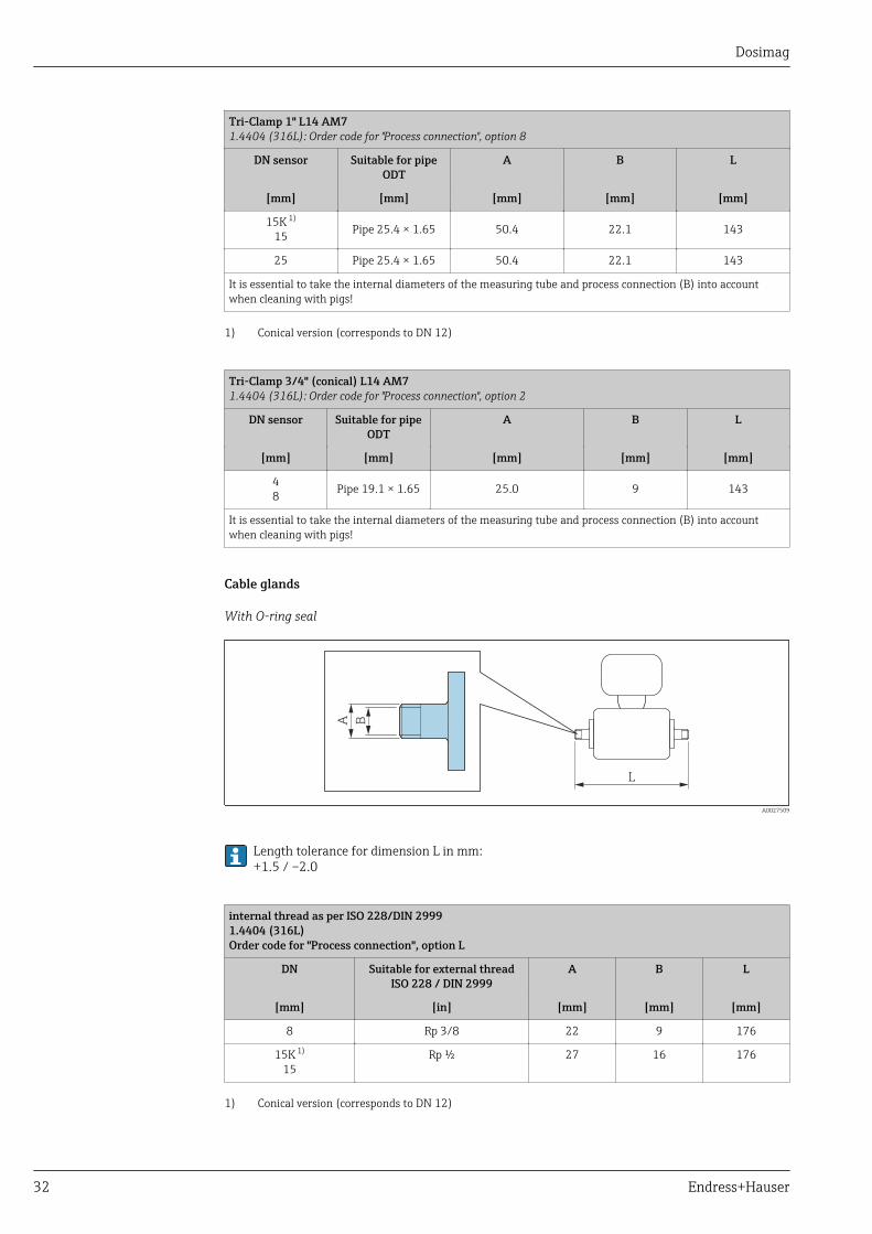
Tri-Clamp 1" L14 AM71.4404 (316L): Order code for "Process connection", option 8
DN sensor Suitable for pipeODT
A B L
[mm] [mm] [mm] [mm] [mm]
15K 1)
15 Pipe 25.4 × 1.65 50.4 22.1 143
25 Pipe 25.4 × 1.65 50.4 22.1 143
It is essential to take the internal diameters of the measuring tube and process connection (B) into accountwhen cleaning with pigs!
1) Conical version (corresponds to DN 12)
Tri-Clamp 3/4" (conical) L14 AM71.4404 (316L): Order code for "Process connection", option 2
DN sensor Suitable for pipeODT
A B L
[mm] [mm] [mm] [mm] [mm]
48 Pipe 19.1 × 1.65 25.0 9 143
It is essential to take the internal diameters of the measuring tube and process connection (B) into accountwhen cleaning with pigs!
Cable glands
With O-ring seal
L
A B
A0027509
Length tolerance for dimension L in mm:+1.5 / –2.0
internal thread as per ISO 228/DIN 29991.4404 (316L)Order code for "Process connection", option L
DN Suitable for external threadISO 228 / DIN 2999
A B L
[mm] [in] [mm] [mm] [mm]
8 Rp 3/8 22 9 176
15K 1)
15Rp ½ 27 16 176
1) Conical version (corresponds to DN 12)
Dosimag
Endress+Hauser 33
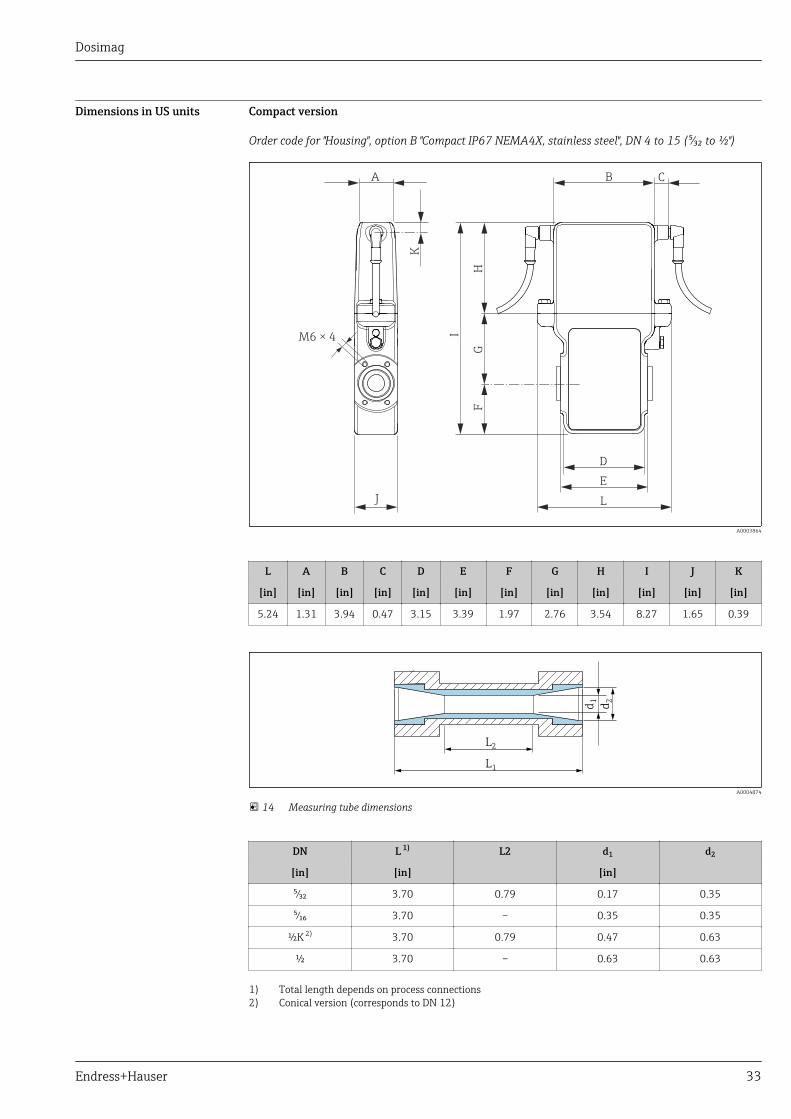
Dimensions in US units Compact version
Order code for "Housing", option B "Compact IP67 NEMA4X, stainless steel", DN 4 to 15 (⁵⁄₃₂ to ½")
L
B
D
EH
I
J
M6 × 4
A C
GF
K
A0003864
L A B C D E F G H I J K
[in] [in] [in] [in] [in] [in] [in] [in] [in] [in] [in] [in]
5.24 1.31 3.94 0.47 3.15 3.39 1.97 2.76 3.54 8.27 1.65 0.39
L2
L1
d1
d2
A0004874
14 Measuring tube dimensions
DN L 1) L2 d1 d2
[in] [in] [in]
⁵⁄₃₂ 3.70 0.79 0.17 0.35
⁵⁄₁₆ 3.70 – 0.35 0.35
½K 2) 3.70 0.79 0.47 0.63
½ 3.70 – 0.63 0.63
1) Total length depends on process connections2) Conical version (corresponds to DN 12)
Dosimag
34 Endress+Hauser
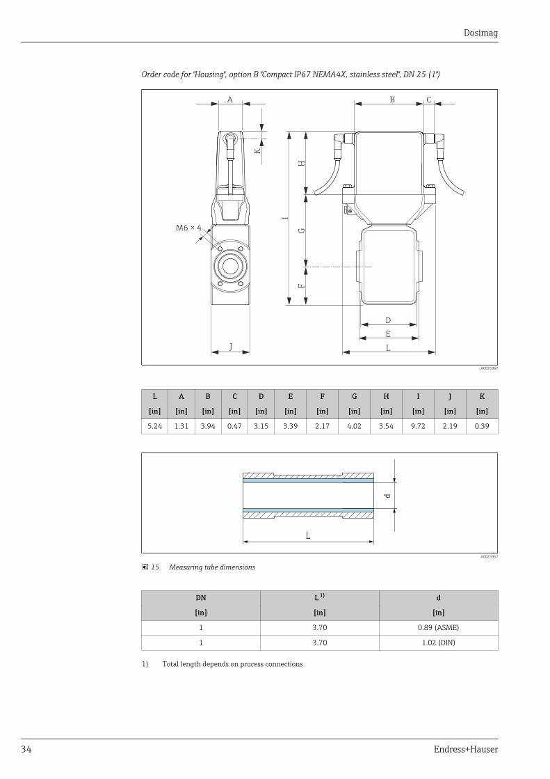
Order code for "Housing", option B "Compact IP67 NEMA4X, stainless steel", DN 25 (1")
L
B
D
E
H
I
J
M6 × 4
A C
GF
K
A0025867
L A B C D E F G H I J K
[in] [in] [in] [in] [in] [in] [in] [in] [in] [in] [in] [in]
5.24 1.31 3.94 0.47 3.15 3.39 2.17 4.02 3.54 9.72 2.19 0.39
L
d
A0025957
15 Measuring tube dimensions
DN L 1) d
[in] [in] [in]
1 3.70 0.89 (ASME)
1 3.70 1.02 (DIN)
1) Total length depends on process connections
Dosimag
Endress+Hauser 35
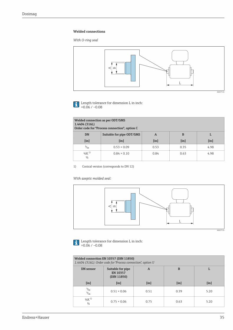
Welded connections
With O-ring seal
L
A B
A0027510
Length tolerance for dimension L in inch:+0.06 / –0.08
Welded connection as per ODT/SMS1.4404 (316L)Order code for "Process connection", option C
DN Suitable for pipe ODT/SMS A B L
[in] [in] [in] [in] [in]
⁵⁄₁₆ 0.53 × 0.09 0.53 0.35 4.98
½K 1)
½0.84 × 0.10 0.84 0.63 4.98
1) Conical version (corresponds to DN 12)
With aseptic molded seal:
L
A B
A0027510
Length tolerance for dimension L in inch:+0.06 / –0.08
Welded connection EN 10357 (DIN 11850)1.4404 (316L): Order code for "Process connection", option U
DN sensor Suitable for pipeEN 10357
(DIN 11850)
A B L
[in] [in] [in] [in] [in]
⁵⁄₃₂⁵⁄₁₆ 0.51 × 0.06 0.51 0.39 5.20
½K 1)
½ 0.75 × 0.06 0.75 0.63 5.20

Dosimag
36 Endress+Hauser
Welded connection EN 10357 (DIN 11850)1.4404 (316L): Order code for "Process connection", option U
DN sensor Suitable for pipeEN 10357
(DIN 11850)
A B L
[in] [in] [in] [in] [in]
1 1.18 × 0.08 1.18 1.02 5.21
It is essential to take the internal diameters of the measuring tube and process connection (B) into accountwhen cleaning with pigs!
1) Conical version (corresponds to DN 12)
Weld-in nipple ODT/SMS1.4404 (316L): Order code for "Process connection", option V
DN sensor Suitable for pipeODT/SMS
A B L
[in] [in] [in] [in] [in]
⁵⁄₃₂⁵⁄₁₆ 0.50 × 0.06 0.47 0.39 4.65
½K 1)
½ 0.75 × 0.06 0.71 0.63 4.65
1 1 × 0.06 1 0.89 4.65
It is essential to take the internal diameters of the measuring tube and process connection (B) into accountwhen cleaning with pigs!
1) Conical version (corresponds to DN 12)
Clamp connections
L
A B
A0015625
Length tolerance for dimension L in inch:+0.06 / –0.08
Tri-Clamp L14 AM71.4404 (316L): Order code for "Process connection", option 1
DN sensor Suitable for pipeODT
A B L
[in] [in] [in] [in] [in]
⁵⁄₃₂⁵⁄₁₆ ODT ½ 0.98 0.37 5.63
½K 1)
½ ODT ¾ 0.62 0.62 5.63

Dosimag
Endress+Hauser 37
Tri-Clamp L14 AM71.4404 (316L): Order code for "Process connection", option 1
DN sensor Suitable for pipeODT
A B L
[in] [in] [in] [in] [in]
1 ODT 1 1.98 0.87 5.63
It is essential to take the internal diameters of the measuring tube and process connection (B) into accountwhen cleaning with pigs!
1) Conical version (corresponds to DN 12)
Tri-Clamp 1" L14 AM71.4404 (316L): Order code for "Process connection", option 8
DN sensor Suitable for pipeODT
A B L
[in] [in] [in] [in] [in]
½K 1)
½ 1 1.98 0.87 5.63
1 1 1.98 0.87 5.63
It is essential to take the internal diameters of the measuring tube and process connection (B) into accountwhen cleaning with pigs!
1) Conical version (corresponds to DN 12)
Tri-Clamp 3/4" (conical) L14 AM71.4404 (316L): Order code for "Process connection", option 2
DN sensor Suitable for pipeODT
A B L
[in] [in] [in] [in] [in]
⁵⁄₃₂⁵⁄₁₆ ODT ¾ 1.12 0.35 5.63
It is essential to take the internal diameters of the measuring tube and process connection (B) into accountwhen cleaning with pigs!
Cable glands
With O-ring seal
L
A B
A0027509
Length tolerance for dimension L in inch:+0.06 / –0.08
Dosimag
38 Endress+Hauser
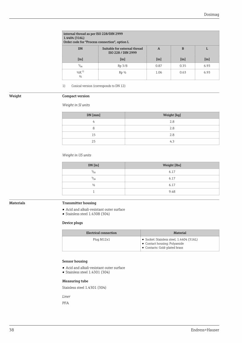
internal thread as per ISO 228/DIN 29991.4404 (316L)Order code for "Process connection", option L
DN Suitable for external threadISO 228 / DIN 2999
A B L
[in] [in] [in] [in] [in]
⁵⁄₁₆ Rp 3/8 0.87 0.35 6.93
½K 1)
½Rp ½ 1.06 0.63 6.93
1) Conical version (corresponds to DN 12)
Weight Compact version
Weight in SI units
DN [mm] Weight [kg]
4 2.8
8 2.8
15 2.8
25 4.3
Weight in US units
DN [in] Weight [lbs]
⁵⁄₃₂ 6.17
⁵⁄₁₆ 6.17
½ 6.17
1 9.48
Materials Transmitter housing
• Acid and alkali-resistant outer surface• Stainless steel 1.4308 (304)
Device plugs
Electrical connection Material
Plug M12x1 • Socket: Stainless steel, 1.4404 (316L)• Contact housing: Polyamide• Contacts: Gold-plated brass
Sensor housing
• Acid and alkali-resistant outer surface• Stainless steel 1.4301 (304)
Measuring tube
Stainless steel 1.4301 (304)
Liner
PFA

Dosimag
Endress+Hauser 39
Electrodes
• 1.4435 (316L)• Alloy C22, 2.4602 (UNS N06022)• Platinum• Tantalum
Process connections
• Weld-in nipple: 1.4404 (316L)• Weld-in nipple, aseptic: 1.4404 (316L)• Tri-Clamp: 1.4404 (316L)• Couplings: 1.4404 (316L)
List of all available process connections → 39
Seals
Molded seal (EPDM, silicone, Viton)
Fitted electrodes • Standard: stainless steel 1.4435 (316L)• Optional: Alloy C22, 2.4602 (UNS N06022), platinum, tantalum
Process connections With O-ring seal
Welded connections• DIN EN ISO 1127• ODT/SMSCouplingISO 228/DIN 2999
With aseptic molded seal:
Welded connections• EN 10357, DIN 11850• ODT/SMSTri-ClampL14 AM7
For information on the different materials used in the process connections → 39
Surface roughness Stainless steel electrodes, 1.4435 (304L); Alloy C22, 2.4602 (UNS N06022), platinum, tantalum:0.3 to 0.5 µm (11.8 to 19.7 µin)Liner with PFA:≤ 0.4 µm (15.7 µin)Process connection:≤ 0.8 µm (31 µin)(All data relate to parts in contact with fluid)
Operability
Local operation This device cannot be operated locally using a display or operating elements.
Remote operation Using service adapter and Commubox FXA291
Operation and configuration can be performed using the Endress+Hauser FieldCare or DeviceCareservice and configuration software.
The device is connected to the USB port of the computer via the service adapter and CommuboxFXA291.
Dosimag
40 Endress+Hauser
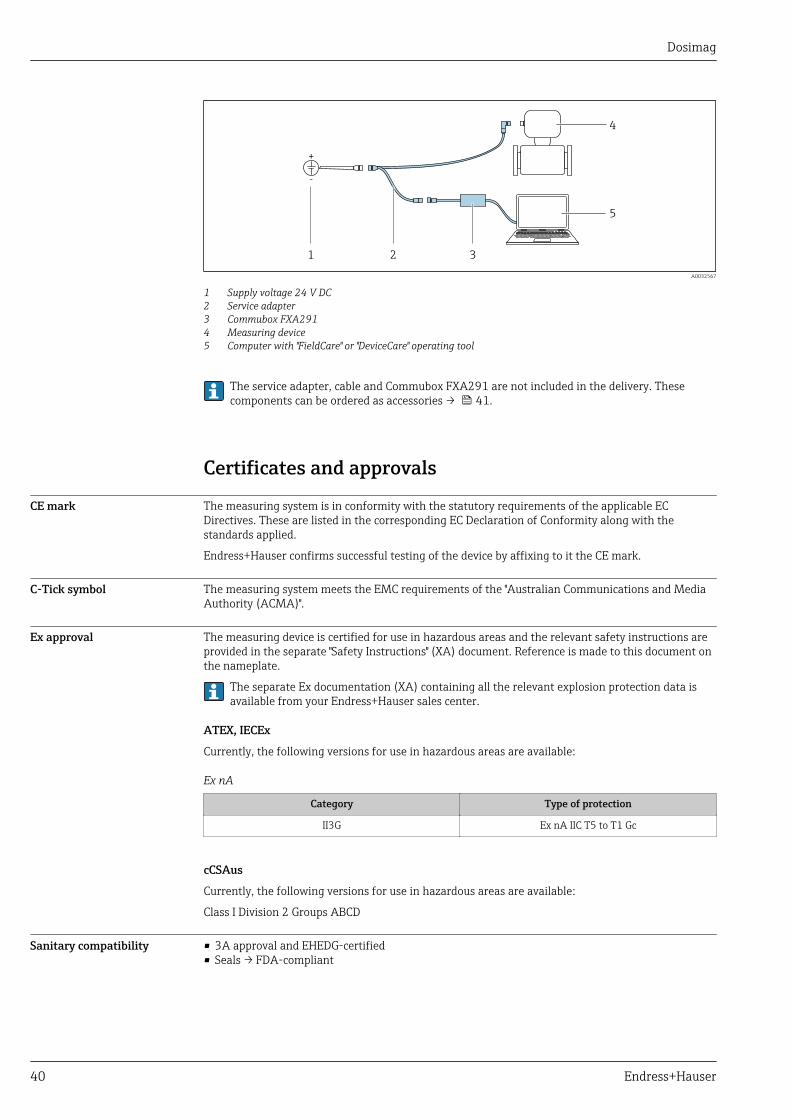
+
-
1 2 3
4
5
A0032567
1 Supply voltage 24 V DC2 Service adapter3 Commubox FXA2914 Measuring device5 Computer with "FieldCare" or "DeviceCare" operating tool
The service adapter, cable and Commubox FXA291 are not included in the delivery. Thesecomponents can be ordered as accessories → 41.
Certificates and approvals
CE mark The measuring system is in conformity with the statutory requirements of the applicable ECDirectives. These are listed in the corresponding EC Declaration of Conformity along with thestandards applied.
Endress+Hauser confirms successful testing of the device by affixing to it the CE mark.
C-Tick symbol The measuring system meets the EMC requirements of the "Australian Communications and MediaAuthority (ACMA)".
Ex approval The measuring device is certified for use in hazardous areas and the relevant safety instructions areprovided in the separate "Safety Instructions" (XA) document. Reference is made to this document onthe nameplate.
The separate Ex documentation (XA) containing all the relevant explosion protection data isavailable from your Endress+Hauser sales center.
ATEX, IECEx
Currently, the following versions for use in hazardous areas are available:
Ex nA
Category Type of protection
II3G Ex nA IIC T5 to T1 Gc
cCSAus
Currently, the following versions for use in hazardous areas are available:
Class I Division 2 Groups ABCD
Sanitary compatibility • 3A approval and EHEDG-certified• Seals → FDA-compliant
Dosimag
Endress+Hauser 41
Pressure EquipmentDirective
• With the PED/G1/x (x = category) marking on the sensor nameplate, Endress+Hauser confirmscompliance with the "Essential Safety Requirements" specified in Annex I of the PressureEquipment Directive 97/23/EC.
• Devices bearing this marking (PED) are suitable for the following types of medium:Media in Group 1 and 2 with a vapor pressure greater than, or smaller and equal to0.5 bar(7.3 psi)
• Devices not bearing this marking (PED) are designed and manufactured according to goodengineering practice. They meet the requirements of Art.3 Section 3 of the Pressure EquipmentDirective 97/23/EC. The range of application is indicated in tables 6 to 9 in Annex II of thePressure Equipment Directive.
Measuring instrumentapproval
Dosimag is suitable as an (optional) component for recording volume in legally regulated measuringsystems for AdBlue / DEF (Diesel Exhaust Fluid) in accordance with Appendix MI-005 of theEuropean Measuring Instruments Directive 2014/32/EU. Dosimag is certified in accordance withOIML R117-1:2007 / OIML R117-2:2014 and has an MID evaluation certificate confirmingconformity with the basic requirements of the Measuring Instruments Directive.
Other standards andguidelines
• EN 60529Degrees of protection provided by enclosures (IP code)
• EN 61010-1Safety Requirements for Electrical Equipment for Measurement, Control and Laboratory Use
• IEC/EN 61326Emission in accordance with Class A requirements. Electromagnetic compatibility (EMCrequirements).
• CAN/CSA C22.2 No. 61010-1-12Safety Requirements for Electrical Equipment for Measurement, Control and Laboratory Use, Part1: General Requirements
• ANSI/ISA-61010-1 (82.02.01)Safety Requirements for Electrical Equipment for Measurement, Control and Laboratory Use – Part1: General Requirements
Ordering informationDetailed ordering information is available from the following sources:• In the Product Configurator on the Endress+Hauser website: www.endress.com -> Click "Corporate"
-> Select your country -> Click "Products" -> Select the product using the filters and search field ->Open product page -> The "Configure" button to the right of the product image opens the ProductConfigurator.
• From your Endress+Hauser Sales Center: www.addresses.endress.comProduct Configurator - the tool for individual product configuration• Up-to-the-minute configuration data• Depending on the device: Direct input of measuring point-specific information such as
measuring range or operating language• Automatic verification of exclusion criteria• Automatic creation of the order code and its breakdown in PDF or Excel output format• Ability to order directly in the Endress+Hauser Online Shop
AccessoriesVarious accessories, which can be ordered with the device or subsequently from Endress+Hauser, areavailable for the device. Detailed information on the order code in question is available from yourlocal Endress+Hauser sales center or on the product page of the Endress+Hauser website:www.endress.com.
Dosimag
42 Endress+Hauser
Device-specific accessories For the sensor
Accessories Description Order code
Seal set For regular replacement of the seals on theprocess connections.
DK5G**-***
Housing seal To seal the transmitter 50102857
Mounting set Consists of:• 2 process connections• Screws• Seals
DKH**-****
Communication-specificaccessories
Accessories Description
FieldCare FDT-based plant asset management tool from Endress+Hauser.It can configure all smart field units in your system and helps you manage them. Byusing the status information, it is also a simple but effective way of checking theirstatus and condition.
For details, see Operating Instructions BA00027S and BA00059S
DeviceCare Tool for connecting and configuring Endress+Hauser field devices.
For details, see Innovation brochure IN01047S
Commubox FXA291 Connects Endress+Hauser field devices with a CDI interface (= Endress+HauserCommon Data Interface) and the USB port of a computer or laptop.
For details, see the "Technical Information" document TI405C/07
Adapter connection Adapter connections for installation on other electrical connections:• Adapter FXA291 (order number: 71035809)• Adapter RSE8 (order number: 50107169)
RSE8 connection jack, 8-pin adapter (RSE8), 24 V DC, pulse, status• Adapter RSE5 (order number: 50107168 )
RSE8 connection jack, 5-pin adapter (RSE5), 24 V DC, pulse, status• Adapter RSE4 (order number: 50107167)
RSE8 connection jack, 4-pin adapter (RSE4), 24 V DC, pulse
Connecting cable RSE8 Cable RKWTN8-56/5 P92, length: 5 m(Order number: 50107895)
Service-specific accessories Accessories Description
Applicator Software for selecting and sizing Endress+Hauser measuring devices:• Calculation of all data required to determine the optimum flowmeter: e.g.
nominal diameter, pressure loss, accuracy or process connections.• Graphic illustration of the calculation results
Administration, documentation and access to all project-related data andparameters throughout the entire life cycle of a project.
Applicator is available:• Via the Internet: https://wapps.endress.com/applicator• On CD-ROM for local PC installation.
W@M Life cycle management for your plantW@M supports you with a wide range of software applications over the entireprocess: from planning and procurement, to the installation, commissioning andoperation of the measuring devices. All the relevant information is available forevery measuring device over time entire life cycle, such as the Device status, spareparts, device-specific documentation.The application already contains the data of your Endress+Hauser device. Endress+Hauser also takes care of maintaining and updating the data records.
W@M is available:• Via the Internet: www.endress.com/lifecyclemanagement• On CD-ROM for local PC installation.

Dosimag
Endress+Hauser 43
FieldCare FDT-based plant asset management tool from Endress+Hauser.It can configure all smart field units in your system and helps you manage them. Byusing the status information, it is also a simple but effective way of checking theirstatus and condition.
For details, see Operating Instructions BA00027S and BA00059S
DeviceCare Tool for connecting and configuring Endress+Hauser field devices.
For details, see Innovation brochure IN01047S
Commubox FXA291 Connects Endress+Hauser field devices with a CDI interface (= Endress+HauserCommon Data Interface) and the USB port of a computer or laptop.
For details, see "Technical Information" TI00405C
Supplementary documentationFor an overview of the scope of the associated Technical Documentation, refer to the following:• The W@M Device Viewer : Enter the serial number from the nameplate
(www.endress.com/deviceviewer)• The Endress+Hauser Operations App: Enter the serial number from the nameplate or scan the
2-D matrix code (QR code) on the nameplate.
Standard documentation Brief Operating Instructions
Measuring device Documentation code
Dosimag KA01175D
Operating Instructions
Measuring device Documentation code
Pulse/frequency/status outputOption 3
Modbus RS485Options 4, 5 and 6
Dosimag BA00098D BA01321D
Description of device parameters
Measuring device Documentation code
Pulse/frequency/status outputOption 3
Modbus RS485Options 4, 5 and 6
Dosimag GP01049D GP01048D
Supplementary device-dependent documentation
Safety Instructions
Contents Documentation code
ATEX/IECEx Ex nA XA01332D
cCSAus FES0231
UL Class 1 Division 2 XA01377D
Special Documentation
Contents Documentation code
Information on Custody Transfer Measurement SD01514D

Dosimag
Registered trademarksModbus®
Registered trademark of SCHNEIDER AUTOMATION, INC.
TRI-CLAMP®
Registered trademark of Ladish & Co., Inc., Kenosha, USA
Applicator®, FieldCare®, DeviceCare®
Registered or registration-pending trademarks of the Endress+Hauser Group
www.addresses.endress.com