dot series - multi-tech dot series at command reference guide 3 contents chapter 1 – introduction...
TRANSCRIPT

DOT SeriesAT Command Reference Guide
DOT SERIES AT COMMAND GUIDE
2 DOT Series AT Command Reference Guide
DOT Series AT Command GuideModels: MTDOT-915-xxx, MTDOT-868-xxx, MTXDOT-915-xx, MTXDOT-898-xx,
Part Number: S000643, Version 3.0
CopyrightThis publication may not be reproduced, in whole or in part, without the specific and express prior written permission signed by an executive officer ofMulti-Tech Systems, Inc. All rights reserved. Copyright © 2017 by Multi-Tech Systems, Inc.
Multi-Tech Systems, Inc. makes no representations or warranties, whether express, implied or by estoppels, with respect to the content, information,material and recommendations herein and specifically disclaims any implied warranties of merchantability, fitness for any particular purpose and non-infringement.
Multi-Tech Systems, Inc. reserves the right to revise this publication and to make changes from time to time in the content hereof without obligation ofMulti-Tech Systems, Inc. to notify any person or organization of such revisions or changes.
Trademarks and Registered TrademarksMultiTech, and the MultiTech logo, and MultiConnect are registered trademarks and mDot, xDot, and Conduit are a trademark of Multi-Tech Systems, Inc.All other products and technologies are the trademarks or registered trademarks of their respective holders.
Legal NoticesThe MultiTech products are not designed, manufactured or intended for use, and should not be used, or sold or re-sold for use, in connection withapplications requiring fail-safe performance or in applications where the failure of the products would reasonably be expected to result in personal injury ordeath, significant property damage, or serious physical or environmental damage. Examples of such use include life support machines or other lifepreserving medical devices or systems, air traffic control or aircraft navigation or communications systems, control equipment for nuclear facilities, ormissile, nuclear, biological or chemical weapons or other military applications (“Restricted Applications”). Use of the products in such RestrictedApplications is at the user’s sole risk and liability.
MULTITECH DOES NOT WARRANT THAT THE TRANSMISSION OF DATA BY A PRODUCT OVER A CELLULAR COMMUNICATIONS NETWORK WILL BEUNINTERRUPTED, TIMELY, SECURE OR ERROR FREE, NOR DOES MULTITECH WARRANT ANY CONNECTION OR ACCESSIBILITY TO ANY CELLULARCOMMUNICATIONS NETWORK. MULTITECH WILL HAVE NO LIABILITY FOR ANY LOSSES, DAMAGES, OBLIGATIONS, PENALTIES, DEFICIENCIES, LIABILITIES,COSTS OR EXPENSES (INCLUDING WITHOUT LIMITATION REASONABLE ATTORNEYS FEES) RELATED TO TEMPORARY INABILITY TO ACCESS A CELLULARCOMMUNICATIONS NETWORK USING THE PRODUCTS.
The MultiTech products and the final application of the MultiTech products should be thoroughly tested to ensure the functionality of the MultiTechproducts as used in the final application. The designer, manufacturer and reseller has the sole responsibility of ensuring that any end user product intowhich the MultiTech product is integrated operates as intended and meets its requirements or the requirements of its direct or indirect customers.MultiTech has no responsibility whatsoever for the integration, configuration, testing, validation, verification, installation, upgrade, support or maintenanceof such end user product, or for any liabilities, damages, costs or expenses associated therewith, except to the extent agreed upon in a signed writtendocument. To the extent MultiTech provides any comments or suggested changes related to the application of its products, such comments or suggestedchanges is performed only as a courtesy and without any representation or warranty whatsoever.
Contacting MultiTech
Knowledge BaseThe Knowledge Base provides immediate access to support information and resolutions for all MultiTech products. Visit http://www.multitech.com/kb.go.
Support PortalTo create an account and submit a support case directly to our technical support team, visit: https://support.multitech.com.
SupportBusiness Hours: M-F, 8am to 5pm CT
Country By Email By Phone
Europe, Middle East, Africa: [email protected] +(44) 118 959 7774
U.S., Canada, all others: [email protected] (800) 972-2439 or (763) 717-5863
WarrantyTo read the warranty statement for your product, visit www.multitech.com/warranty.go. For other warranty options, visit www.multitech.com/es.go.
World Headquarters
Multi-Tech Systems, Inc.
2205 Woodale Drive, Mounds View, MN 55112
Phone: (800) 328-9717 or (763) 785-3500
Fax (763) 785-9874
CONTENTS
DOT Series AT Command Reference Guide 3
ContentsChapter 1 – Introduction.......................................................................................................................................... 8
AT Commands ............................................................................................................................................................... 8Using Commands .......................................................................................................................................................... 8
Querying...................................................................................................................................................................... 8Assigning New Values ................................................................................................................................................. 8
Terminology .................................................................................................................................................................. 9LoRa Topology............................................................................................................................................................... 9
Chapter 2 – General AT Commands........................................................................................................................ 10AT Attention ............................................................................................................................................................... 10
Syntax........................................................................................................................................................................ 10Parameters and Values ............................................................................................................................................. 10Command with Response Examples ......................................................................................................................... 10
ATI Request ID ............................................................................................................................................................ 10Syntax ....................................................................................................................................................................... 10Parameters and Values ............................................................................................................................................. 10Command with Response Examples ......................................................................................................................... 11
ATZ Reset CPU ............................................................................................................................................................ 11Syntax........................................................................................................................................................................ 11Parameters and values.............................................................................................................................................. 11Command with Response Examples ......................................................................................................................... 11
ATE0/1 Echo Mode ..................................................................................................................................................... 12Syntax........................................................................................................................................................................ 12Parameters and Values ............................................................................................................................................. 12Command with Response Examples ......................................................................................................................... 12
ATV0/1 Verbose Mode ............................................................................................................................................... 12Syntax ....................................................................................................................................................................... 12Parameters and Values ............................................................................................................................................. 13Command with Response Examples ......................................................................................................................... 13
AT&K0/3 Hardware Flow Control .............................................................................................................................. 13Syntax ....................................................................................................................................................................... 13Parameters and Values ............................................................................................................................................. 13Command with Response Examples ......................................................................................................................... 13
AT&F Reset to Factory Defaults ................................................................................................................................. 14Syntax ....................................................................................................................................................................... 14Parameters and Values ............................................................................................................................................. 14Command with Response Examples ......................................................................................................................... 14Example US 915MHz ................................................................................................................................................. 14Example EU 868MHz................................................................................................................................................. 16
CONTENTS
4 DOT Series AT Command Reference Guide
AT&W Save Configuration .......................................................................................................................................... 18Syntax ....................................................................................................................................................................... 18Parameters and Values ............................................................................................................................................. 18Command with Response Examples ......................................................................................................................... 18
AT+WP Wake Pin ........................................................................................................................................................ 19Syntax ....................................................................................................................................................................... 19Parameters and Values ............................................................................................................................................. 19Command with Response Examples ......................................................................................................................... 19
AT+IPR Serial Speed ................................................................................................................................................... 20Syntax........................................................................................................................................................................ 20Parameters and Values ............................................................................................................................................. 20Command with Response Examples ......................................................................................................................... 20
AT+DIPR Debug Serial Speed ..................................................................................................................................... 21Syntax........................................................................................................................................................................ 21Parameters and Values ............................................................................................................................................. 21Command with Response Examples ......................................................................................................................... 21
AT+LOG Debug Log Level ........................................................................................................................................... 22Syntax ....................................................................................................................................................................... 22Parameters and Values ............................................................................................................................................. 22Command with Response Examples ......................................................................................................................... 22
Chapter 3 – Network Management........................................................................................................................ 24Configuring.................................................................................................................................................................. 24
AT+DI Device ID ........................................................................................................................................................ 24AT+DFREQ Default Frequency Band ........................................................................................................................ 25AT+FREQ Frequency Band ........................................................................................................................................ 26AT+FSB Frequency Sub-Band (915MHz models only)............................................................................................... 27AT+PN Public Network Mode .................................................................................................................................. 28AT+JBO Join Byte Order ........................................................................................................................................... 30AT+NJM Network Join Mode ................................................................................................................................... 31AT+JOIN Join Network .............................................................................................................................................. 32AT+JR Join Retries ..................................................................................................................................................... 33AT+JD Join Delay ...................................................................................................................................................... 33
Over-the-Air Activation (OTA)..................................................................................................................................... 35AT+NI Network ID .................................................................................................................................................... 35AT+NK Network Key ................................................................................................................................................. 36AT+ENC AES Encryption ........................................................................................................................................... 37
Manual Activation....................................................................................................................................................... 38AT+NA Network Address .......................................................................................................................................... 38AT+NSK Network Session Key .................................................................................................................................. 39AT+DSK Data Session Key ......................................................................................................................................... 39AT+ULC Uplink Counter ............................................................................................................................................ 40

CONTENTS
DOT Series AT Command Reference Guide 5
AT+DLC Downlink Counter........................................................................................................................................ 41Network Joining .......................................................................................................................................................... 42
OTA Network Join ..................................................................................................................................................... 42Auto OTA Network Join............................................................................................................................................. 42
Ensuring Network Connectivity................................................................................................................................... 42AT+NJS Network Join Status .................................................................................................................................... 42AT+PING Send Ping ................................................................................................................................................... 43AT+ACK Require Acknowledgment ........................................................................................................................... 44AT+NLC Network Link Check .................................................................................................................................... 45AT+LCC Link Check Count ......................................................................................................................................... 46AT+LCT Link Check Threshold .................................................................................................................................. 47
Preserving, Saving, and Restoring Sessions ................................................................................................................ 47AT+SS Save Network Session ................................................................................................................................... 47AT+RS Restore Network Session .............................................................................................................................. 48AT+PS Preserve Session ........................................................................................................................................... 49
Chapter 4 – Sending and Receiving Packets............................................................................................................ 50Channels and Duty Cycles ........................................................................................................................................... 50
AT+CHM Channel Mask ............................................................................................................................................ 50AT+TXCH Transmit Channel ..................................................................................................................................... 51AT+LBT Listen Before Talk ........................................................................................................................................ 54AT+TXN Transmit Next ............................................................................................................................................. 55AT+TOA Time On Air ................................................................................................................................................ 56
Configuring.................................................................................................................................................................. 57AT+MAC Inject MAC Command ............................................................................................................................... 57AT&V Settings and Status ........................................................................................................................................ 59AT+DC Device Class .................................................................................................................................................. 61AT+AP Application Port ............................................................................................................................................ 62AT+TXP Transmit Power ........................................................................................................................................... 63AT+TXI Transmit Inverted ........................................................................................................................................ 63AT+RXI Receive Signal Inverted ................................................................................................................................ 64AT+RXD Receive Delay ............................................................................................................................................. 65AT+FEC Forward Error Correction ............................................................................................................................ 66AT+CRC Cyclical Redundancy Check ........................................................................................................................ 67AT+ADR Adaptive Data Rate .................................................................................................................................... 68AT+TXDR TX Data Rate ............................................................................................................................................. 68AT+SDR Session Data Rate ........................................................................................................................................ 70AT+REP Repeat Packet ............................................................................................................................................. 70
Sending Packets .......................................................................................................................................................... 71AT+SEND Send .......................................................................................................................................................... 71AT+SENDB Send Binary ............................................................................................................................................ 73
Receiving Packets ........................................................................................................................................................ 74
CONTENTS
6 DOT Series AT Command Reference Guide
AT+RECV Receive Once ............................................................................................................................................ 74AT+RXO Receive Output .......................................................................................................................................... 75AT+DP Data Pending ................................................................................................................................................ 75AT+TXW Transmit Wait ............................................................................................................................................ 76
Statistics ...................................................................................................................................................................... 77AT&R Reset Statistics ............................................................................................................................................... 77AT&S Statistics ......................................................................................................................................................... 78AT+RSSI Signal Strength ........................................................................................................................................... 79AT+SNR Signal to Noise Ratio .................................................................................................................................. 79
Serial Data Mode......................................................................................................................................................... 80AT+SD Serial Data Mode ........................................................................................................................................... 80AT+SMODE Startup Mode ........................................................................................................................................ 81AT+SDCE Serial Data Clear on Error ......................................................................................................................... 82
Chapter 5 – Power Management ........................................................................................................................... 84AT+SLEEP Sleep Mode ................................................................................................................................................ 84
Syntax ....................................................................................................................................................................... 84Parameters and Values ............................................................................................................................................. 84Command with Response Examples ......................................................................................................................... 84
AT+WM Wake Mode .................................................................................................................................................. 85Syntax ....................................................................................................................................................................... 85Parameters and Values ............................................................................................................................................. 85Command with Response Examples ......................................................................................................................... 85
AT+WI Wake Interval ................................................................................................................................................. 85Syntax ....................................................................................................................................................................... 86Parameters and Values ............................................................................................................................................. 86Command with Response Examples ......................................................................................................................... 86
AT+WD Wake Delay ................................................................................................................................................... 86Syntax ....................................................................................................................................................................... 86Parameters and Values ............................................................................................................................................. 87Command with Response Examples ......................................................................................................................... 87
AT+WTO Wake Timeout ............................................................................................................................................. 87Syntax ....................................................................................................................................................................... 87Parameters and Values ............................................................................................................................................. 87Command with Response Examples ......................................................................................................................... 88
AT+ANT Antenna Gain ............................................................................................................................................... 88Syntax ....................................................................................................................................................................... 88Parameters and Values ............................................................................................................................................. 88Command with Response Examples ......................................................................................................................... 88
Chapter 6 – Testing and Compliance ...................................................................................................................... 90AT+RXDR Receive Data Rate ...................................................................................................................................... 90
Syntax ....................................................................................................................................................................... 90

CONTENTS
DOT Series AT Command Reference Guide 7
Parameters and Values ............................................................................................................................................. 90Command with Response Examples ......................................................................................................................... 90EU 868MHz................................................................................................................................................................ 90
AT+RXF Receive Frequency ........................................................................................................................................ 91Syntax ....................................................................................................................................................................... 91Parameters and Values ............................................................................................................................................. 91Command with Response Examples ......................................................................................................................... 91
AT+RECVC Receive Continuously ............................................................................................................................... 91Syntax ....................................................................................................................................................................... 92Parameters and Values ............................................................................................................................................. 92Command with Response Examples ......................................................................................................................... 92
AT+SENDI Send on Interval ........................................................................................................................................ 92Syntax ....................................................................................................................................................................... 92Parameters and Values ............................................................................................................................................. 92Command with Response Examples ......................................................................................................................... 93
AT+TXF Transmit Frequency ...................................................................................................................................... 93Syntax ....................................................................................................................................................................... 93Parameters and Values ............................................................................................................................................. 93Command with Response Examples ......................................................................................................................... 94US 915MHz................................................................................................................................................................ 94EU 868 MHz............................................................................................................................................................... 94
Chapter 7 – Examples............................................................................................................................................. 95Network Configuration and Joining ........................................................................................................................... 95US 915MHz - Frequency Sub-band ............................................................................................................................. 95Join Mode.................................................................................................................................................................... 96Ensuring Network Connectivity................................................................................................................................... 97Serial Mode ................................................................................................................................................................ 98Peer to Peer ................................................................................................................................................................ 99
Configuration ............................................................................................................................................................ 99Peer-to-Peer Throughput........................................................................................................................................ 100

INTRODUCTION
8 DOT Series AT Command Reference Guide
Chapter 1 – IntroductionAT CommandsThis reference provides AT Command information for the MultiTech Dot Series. These commands are available infirmware Version 2.0.x. Note that some commands are not available in older firmware versions.
For mDot firmware upgrade instructions and to download the latest firmware, go tohttp://www.multitech.net/developer/software/mdot-software/mdot-firmware-upgrade/.For xDot firmware upgrade instructions and to download the latest firmware, go tohttp://www.multitech.net/developer/downloads/#xdot
Using CommandsQueryingSome commands allow you to query the current value. Enter the command with no argument or followed by aquestion mark (?):
Query a value
AT+TXP11
OK
Query a value with optional ?
AT+TXP?11
OK
Assigning New ValuesSome commands allow you to assign a new value:
To assign a new value, pass the value as an argument
AT+TXP=10
OK
To see a range of input or output values for a command, give ? at the only argument.
AT+TXPAT+TXP: (0-20)
OK
INTRODUCTION
DOT Series AT Command Reference Guide 9
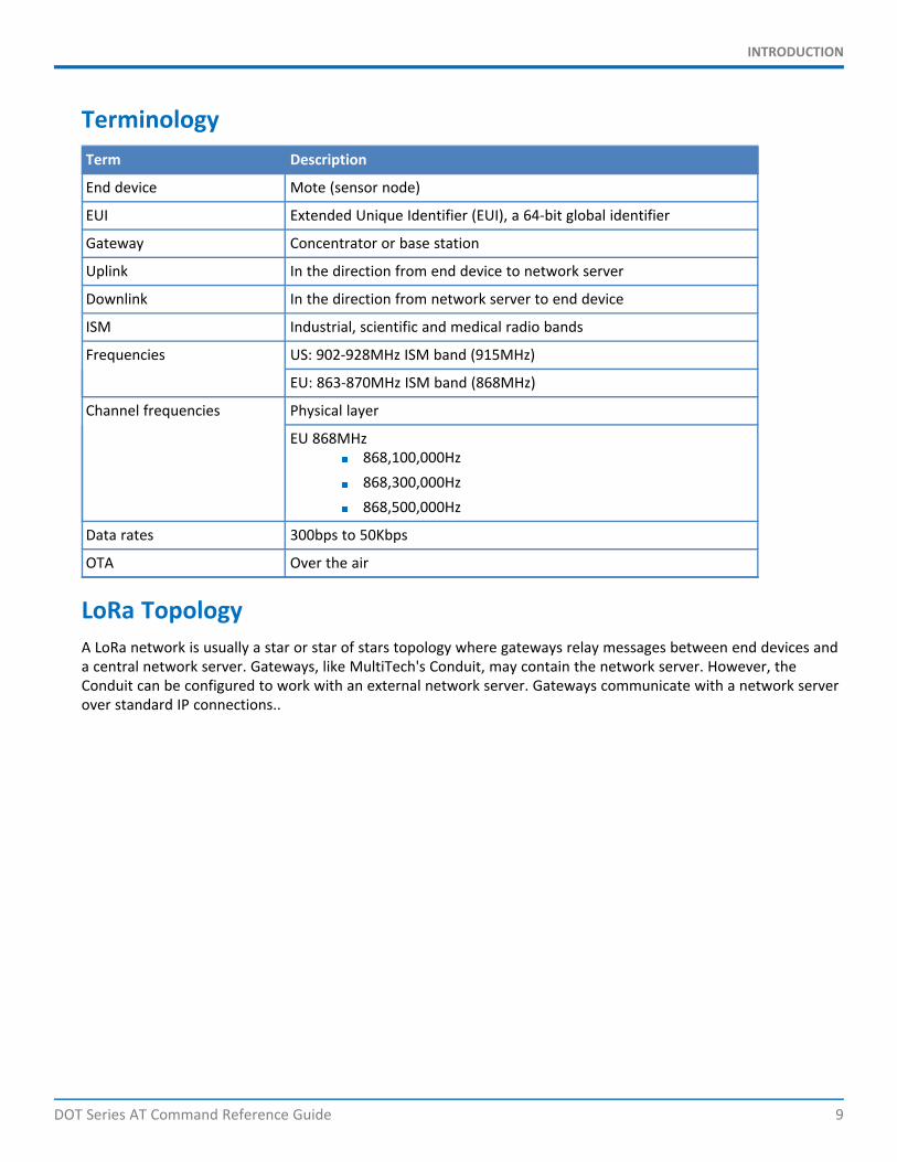
TerminologyTerm Description
End device Mote (sensor node)
EUI Extended Unique Identifier (EUI), a 64-bit global identifier
Gateway Concentrator or base station
Uplink In the direction from end device to network server
Downlink In the direction from network server to end device
ISM Industrial, scientific and medical radio bands
Frequencies US: 902-928MHz ISM band (915MHz)
EU: 863-870MHz ISM band (868MHz)
Channel frequencies Physical layer
EU 868MHz868,100,000Hz868,300,000Hz868,500,000Hz
Data rates 300bps to 50Kbps
OTA Over the air
LoRa TopologyA LoRa network is usually a star or star of stars topology where gateways relay messages between end devices anda central network server. Gateways, like MultiTech's Conduit, may contain the network server. However, theConduit can be configured to work with an external network server. Gateways communicate with a network serverover standard IP connections..
GENERAL AT COMMANDS
10 DOT Series AT Command Reference Guide
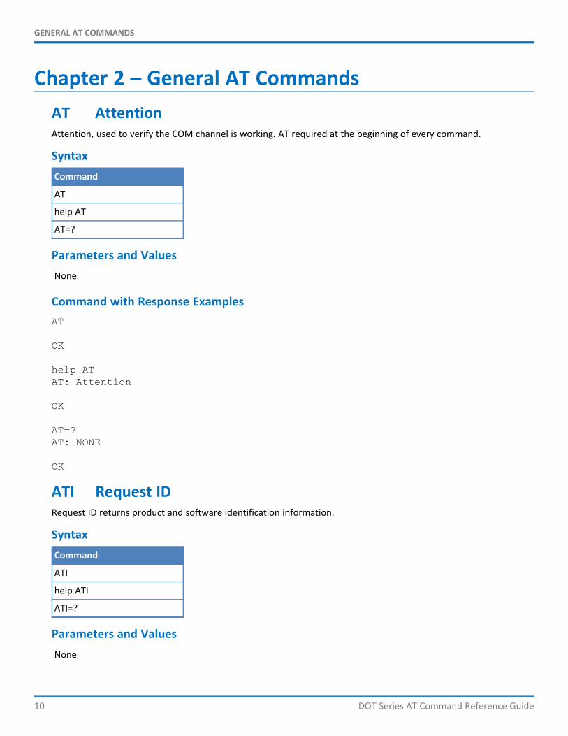
Chapter 2 – General AT CommandsAT AttentionAttention, used to verify the COM channel is working. AT required at the beginning of every command.
SyntaxCommand
AT
help AT
AT=?
Parameters and ValuesNone
Command with Response ExamplesAT
OK
help ATAT: Attention
OK
AT=?AT: NONE
OK
ATI Request IDRequest ID returns product and software identification information.
SyntaxCommand
ATI
help ATI
ATI=?
Parameters and ValuesNone
GENERAL AT COMMANDS
DOT Series AT Command Reference Guide 11
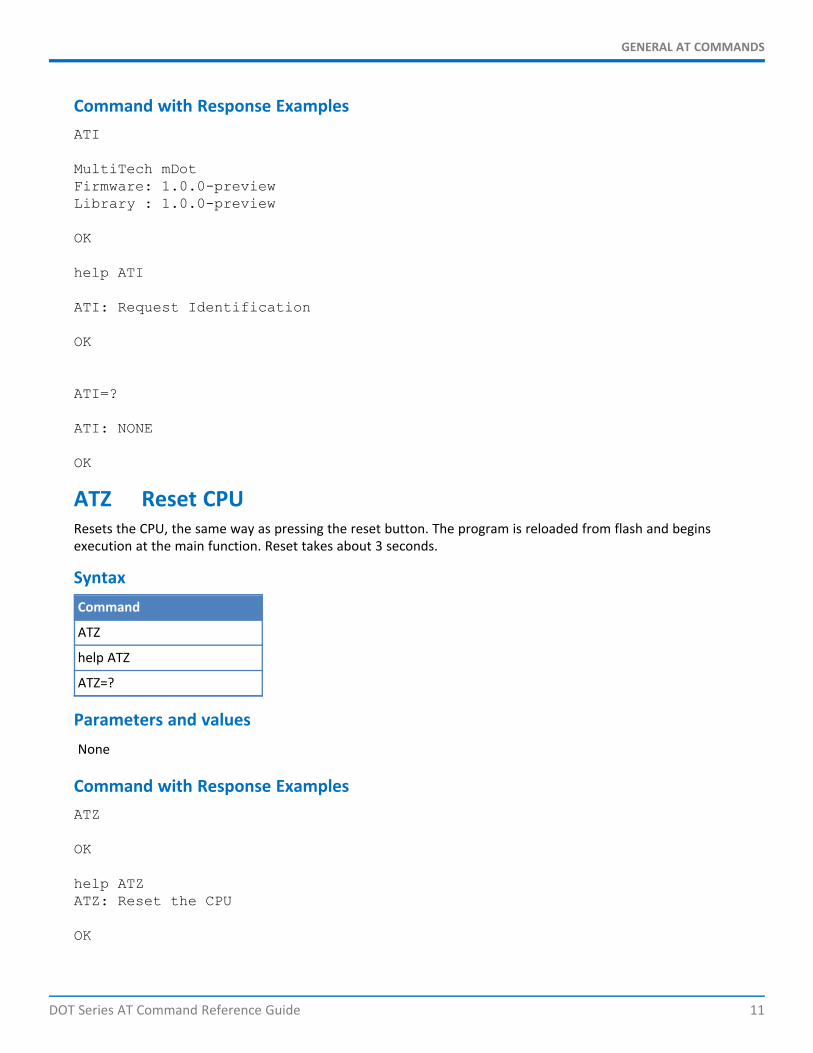
Command with Response ExamplesATI
MultiTech mDotFirmware: 1.0.0-previewLibrary : 1.0.0-preview
OK
help ATI
ATI: Request Identification
OK
ATI=?
ATI: NONE
OK
ATZ Reset CPUResets the CPU, the same way as pressing the reset button. The program is reloaded from flash and beginsexecution at the main function. Reset takes about 3 seconds.
SyntaxCommand
ATZ
help ATZ
ATZ=?
Parameters and valuesNone
Command with Response ExamplesATZ
OK
help ATZATZ: Reset the CPU
OK
GENERAL AT COMMANDS
12 DOT Series AT Command Reference Guide
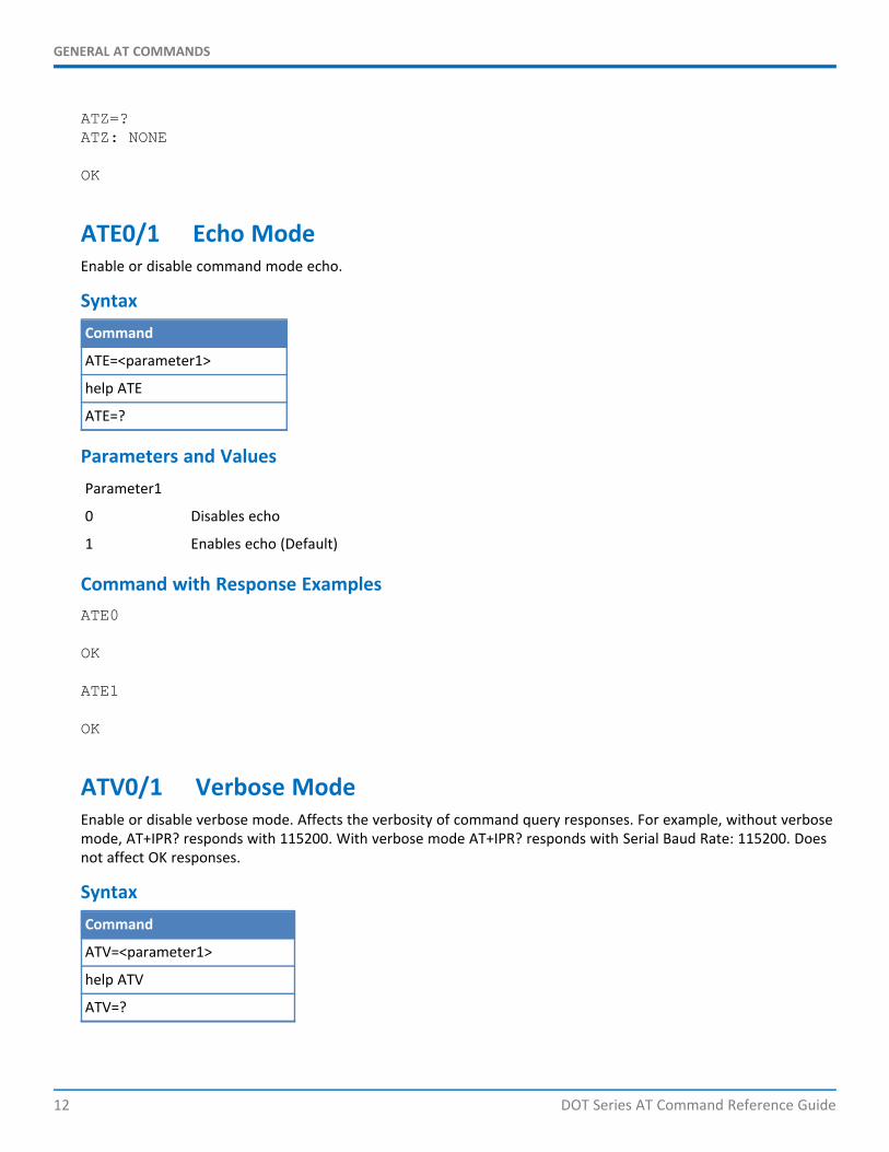
ATZ=?ATZ: NONE
OK
ATE0/1 Echo ModeEnable or disable command mode echo.
SyntaxCommand
ATE=<parameter1>
help ATE
ATE=?
Parameters and ValuesParameter1
0 Disables echo
1 Enables echo (Default)
Command with Response ExamplesATE0
OK
ATE1
OK
ATV0/1 Verbose ModeEnable or disable verbose mode. Affects the verbosity of command query responses. For example, without verbosemode, AT+IPR? responds with 115200. With verbose mode AT+IPR? responds with Serial Baud Rate: 115200. Doesnot affect OK responses.
SyntaxCommand
ATV=<parameter1>
help ATV
ATV=?
GENERAL AT COMMANDS
DOT Series AT Command Reference Guide 13
Parameters and ValuesParameter1
0 Disables verbose mode (Default)
1 Enables verbose mode
Command with Response ExamplesATV0
OK
ATV1
OK
AT&K0/3 Hardware Flow ControlEnable or disable hardware flow control. Hardware flow control is useful in serial data mode to keep fromoverflowing the input buffers.
This uses pins NCTS_DIO7(CTS) and RTS_AD6_DIO6(RTS). When in serial data mode, use hardware flow control toprevent buffer overflow. (Serial data mode is AT+SMODE=1 or AT+SD.) Changes CTS signal to low with &K0 and tohigh with &K3.
Note: RTS of the dot pinout is an output. When used as a DCE device, connect this RTS pin to the CTS of aconnected DTE device. The dot RTS pin is an input and connects to CTS of a DTE interface.
SyntaxCommand
AT&K=<parameter1>
help AT&K
AT&K=?
Parameters and ValuesParameter1
0 Disables hardware flow control
3 Enables hardware flow control
Command with Response ExamplesAT&K0
OK
AT&K3
GENERAL AT COMMANDS
14 DOT Series AT Command Reference Guide
OK
AT&K?3
OK
help AT&KAT&K: AT&K0: disable, AT&K3: enable
OK
AT&F Reset to Factory DefaultsChanges the current settings to the factory defaults, but does not store them. To store the default settings, usewith AT&W. Otherwise, resetting or power cycling the device restores the previous settings.
SyntaxCommand
AT&F
help AT&F
AT&F=?
Parameters and ValuesNone
Command with Response ExamplesAT&F
OK
help AT&FAT&F: Reset current configuration to factory defaults
OK
AT&F=?AT&F: NONE
OK
Example US 915MHz
AT&F
GENERAL AT COMMANDS
DOT Series AT Command Reference Guide 15
OK
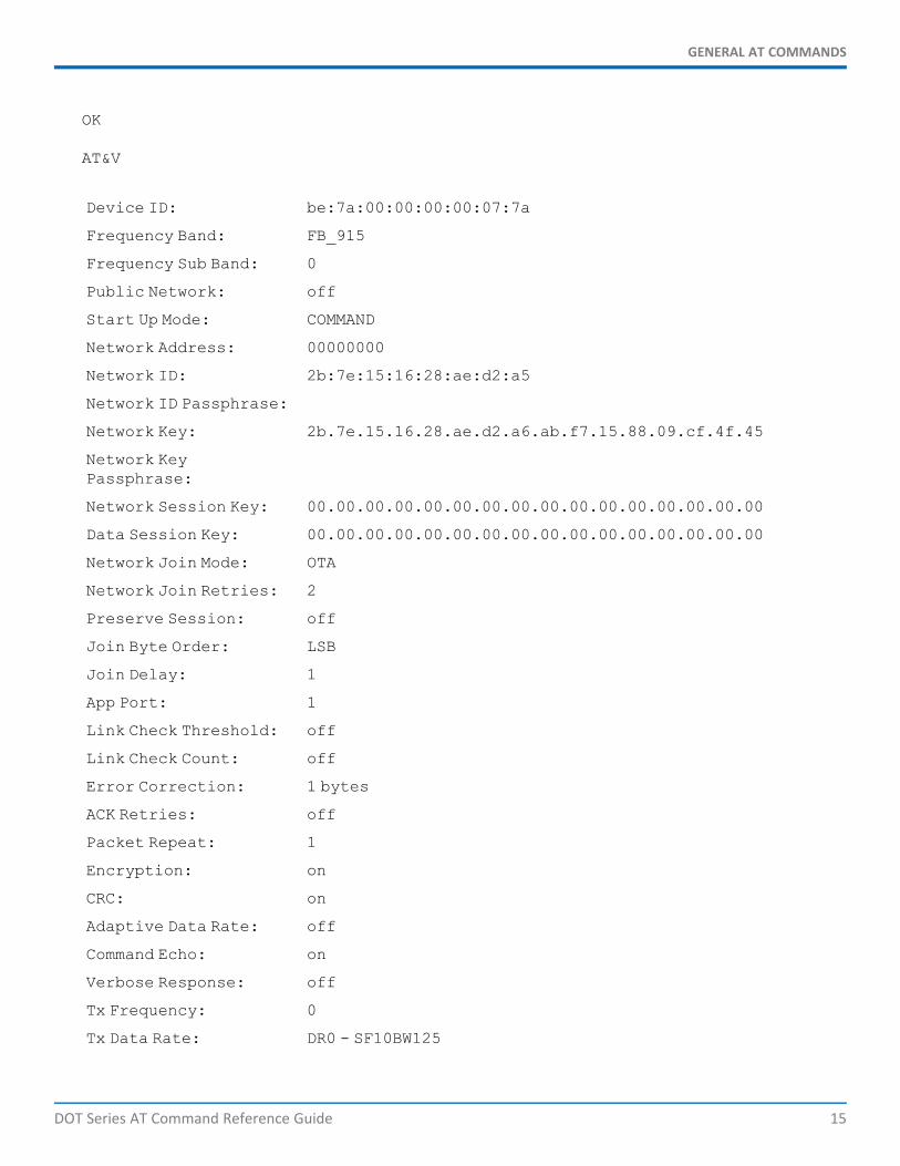
AT&V
Device ID: be:7a:00:00:00:00:07:7a
Frequency Band: FB_915
Frequency Sub Band: 0
Public Network: off
Start Up Mode: COMMAND
Network Address: 00000000
Network ID: 2b:7e:15:16:28:ae:d2:a5
Network ID Passphrase:
Network Key: 2b.7e.15.16.28.ae.d2.a6.ab.f7.15.88.09.cf.4f.45
Network KeyPassphrase:
Network Session Key: 00.00.00.00.00.00.00.00.00.00.00.00.00.00.00.00
Data Session Key: 00.00.00.00.00.00.00.00.00.00.00.00.00.00.00.00
Network Join Mode: OTA
Network Join Retries: 2
Preserve Session: off
Join Byte Order: LSB
Join Delay: 1
App Port: 1
Link Check Threshold: off
Link Check Count: off
Error Correction: 1 bytes
ACK Retries: off
Packet Repeat: 1
Encryption: on
CRC: on
Adaptive Data Rate: off
Command Echo: on
Verbose Response: off
Tx Frequency: 0
Tx Data Rate: DR0 - SF10BW125

GENERAL AT COMMANDS
16 DOT Series AT Command Reference Guide
Tx Power: 11
Tx Antenna Gain: 3
Tx Wait: on
Tx Inverted Signal: off
Rx Delay: 1 s
Rx Inverted Signal: on
Rx Output Style: HEXADECIMAL
Debug Baud Rate: 115200
Serial Baud Rate: 115200
Serial Flow Control: off
Serial Clear On Error: on
Wake Mode: INTERVAL
Wake Interval: 10 s
Wake Delay: 100 ms
Wake Timeout: 20 ms
Wake Pin: DI8
Log Level: 0
OK
Example EU 868MHz
AT&F
OK
AT&V
Device ID: be:7a:00:00:00:00:07:7a
Frequency Band: FB_868
Frequency Sub Band: 0
Public Network: off
Start Up Mode: COMMAND
Network Address: 00000000
Network ID: 2b:7e:15:16:28:ae:d2:a5
Network ID Passphrase:
Network Key: 2b.7e.15.16.28.ae.d2.a6.ab.f7.15.88.09.cf.4f.45
GENERAL AT COMMANDS
DOT Series AT Command Reference Guide 17
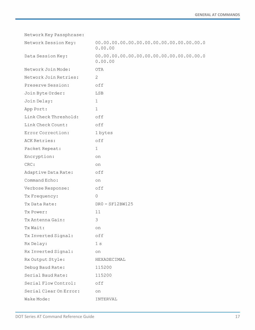
Network Key Passphrase:
Network Session Key: 00.00.00.00.00.00.00.00.00.00.00.00.00.00.00.00
Data Session Key: 00.00.00.00.00.00.00.00.00.00.00.00.00.00.00.00
Network Join Mode: OTA
Network Join Retries: 2
Preserve Session: off
Join Byte Order: LSB
Join Delay: 1
App Port: 1
Link Check Threshold: off
Link Check Count: off
Error Correction: 1 bytes
ACK Retries: off
Packet Repeat: 1
Encryption: on
CRC: on
Adaptive Data Rate: off
Command Echo: on
Verbose Response: off
Tx Frequency: 0
Tx Data Rate: DR0 - SF12BW125
Tx Power: 11
Tx Antenna Gain: 3
Tx Wait: on
Tx Inverted Signal: off
Rx Delay: 1 s
Rx Inverted Signal: on
Rx Output Style: HEXADECIMAL
Debug Baud Rate: 115200
Serial Baud Rate: 115200
Serial Flow Control: off
Serial Clear On Error: on
Wake Mode: INTERVAL
GENERAL AT COMMANDS
18 DOT Series AT Command Reference Guide
Wake Interval: 10 s
Wake Delay: 100 ms
Wake Timeout: 20 ms
Wake Pin: DI8
Log Level: 0
OK
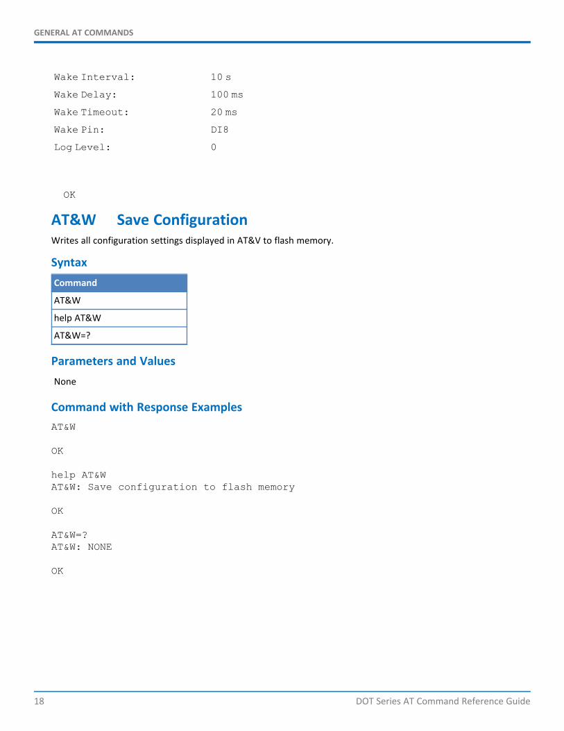
AT&W Save ConfigurationWrites all configuration settings displayed in AT&V to flash memory.
SyntaxCommand
AT&W
help AT&W
AT&W=?
Parameters and ValuesNone
Command with Response ExamplesAT&W
OK
help AT&WAT&W: Save configuration to flash memory
OK
AT&W=?AT&W: NONE
OK
GENERAL AT COMMANDS
DOT Series AT Command Reference Guide 19
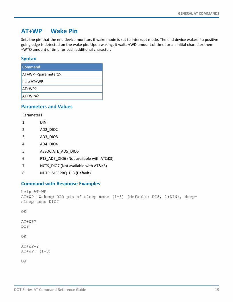
AT+WP Wake PinSets the pin that the end device monitors if wake mode is set to interrupt mode. The end device wakes if a positivegoing edge is detected on the wake pin. Upon waking, it waits +WD amount of time for an initial character then+WTO amount of time for each additional character.
SyntaxCommand
AT+WP=<parameter1>
help AT+WP
AT+WP?
AT+WP=?
Parameters and ValuesParameter1
1 DIN
2 AD2_DIO2
3 AD3_DIO3
4 AD4_DIO4
5 ASSOCIATE_AD5_DIO5
6 RTS_AD6_DIO6 (Not available with AT&K3)
7 NCTS_DIO7 (Not available with AT&K3)
8 NDTR_SLEEPRQ_DI8 (Default)
Command with Response Exampleshelp AT+WPAT+WP: Wakeup DIO pin of sleep mode (1-8) (default: DI8, 1:DIN), deep-sleep uses DIO7
OK
AT+WP?DI8
OK
AT+WP=?AT+WP: (1-8)
OK
GENERAL AT COMMANDS
20 DOT Series AT Command Reference Guide
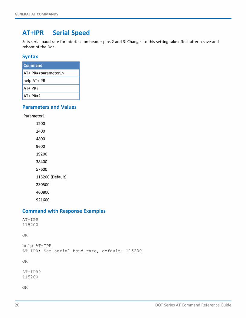
AT+IPR Serial SpeedSets serial baud rate for interface on header pins 2 and 3. Changes to this setting take effect after a save andreboot of the Dot.
SyntaxCommand
AT+IPR=<parameter1>
help AT+IPR
AT+IPR?
AT+IPR=?
Parameters and ValuesParameter1
1200
2400
4800
9600
19200
38400
57600
115200 (Default)
230500
460800
921600
Command with Response ExamplesAT+IPR115200
OK
help AT+IPRAT+IPR: Set serial baud rate, default: 115200
OK
AT+IPR?115200
OK

GENERAL AT COMMANDS
DOT Series AT Command Reference Guide 21
AT+IPR=?AT+IPR: (2400,4800,9600,19200,38400,57600,115200,230400,460800,921600)
OK
AT+DIPR Debug Serial SpeedSets debug serial baud rate for interface on DEBUG header pins 30 and 31. Changes to this setting take effect aftera save and reboot of the Dot. power-cycle or reset.
SyntaxCommand
AT+DIPR=<parameter1>
help AT+DIPR
AT+DIPR?
AT+DIPR=?
Parameters and ValuesParameter1
2400
4800
9600
19200
38400
57600
115200 (Default)
230500
460800
921600
Command with Response ExamplesAT+DIPR115200
OK
help AT+DIPRAT+DIPR: Set debug serial baud rate, default: 115200
OK
GENERAL AT COMMANDS
22 DOT Series AT Command Reference Guide
AT+DIPR?115200
OK
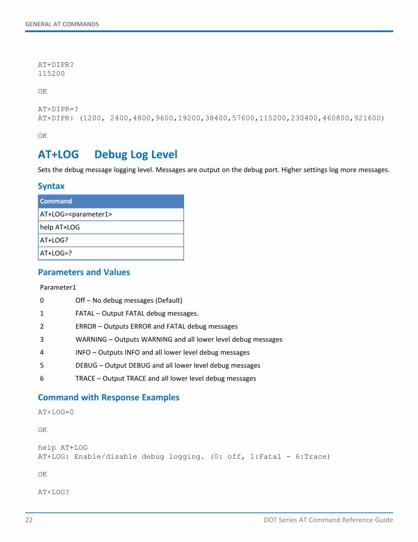
AT+DIPR=?AT+DIPR: (1200, 2400,4800,9600,19200,38400,57600,115200,230400,460800,921600)
OK
AT+LOG Debug Log LevelSets the debug message logging level. Messages are output on the debug port. Higher settings log more messages.
SyntaxCommand
AT+LOG=<parameter1>
help AT+LOG
AT+LOG?
AT+LOG=?
Parameters and ValuesParameter1
0 Off – No debug messages (Default)
1 FATAL – Output FATAL debug messages.
2 ERROR – Outputs ERROR and FATAL debug messages
3 WARNING – Outputs WARNING and all lower level debug messages
4 INFO – Outputs INFO and all lower level debug messages
5 DEBUG – Output DEBUG and all lower level debug messages
6 TRACE – Output TRACE and all lower level debug messages
Command with Response ExamplesAT+LOG=0
OK
help AT+LOGAT+LOG: Enable/disable debug logging. (0: off, 1:Fatal - 6:Trace)
OK
AT+LOG?

GENERAL AT COMMANDS
DOT Series AT Command Reference Guide 23
0
OK
AT+LOG=?AT+LOG: (0-6)
OK
NETWORK MANAGEMENT
24 DOT Series AT Command Reference Guide
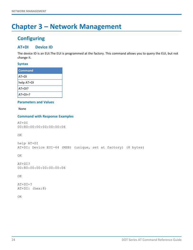
Chapter 3 – Network ManagementConfiguringAT+DI Device IDThe device ID is an EUI.The EUI is programmed at the factory. This command allows you to query the EUI, but notchange it.
Syntax
Command
AT+DI
help AT+DI
AT+DI?
AT+DI=?
Parameters and Values
None
Command with Response Examples
AT+DI00:80:00:00:00:00:00:06
OK
help AT+DIAT+DI: Device EUI-64 (MSB) (unique, set at factory) (8 bytes)
OK
AT+DI?00:80:00:00:00:00:00:06
OK
AT+DI=?AT+DI: (hex:8)
OK
NETWORK MANAGEMENT
DOT Series AT Command Reference Guide 25
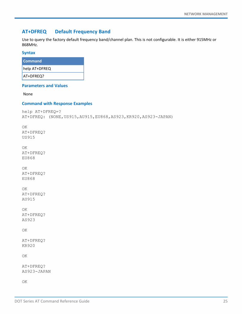
AT+DFREQ Default Frequency BandUse to query the factory default frequency band/channel plan. This is not configurable. It is either 915MHz or868MHz.
Syntax
Command
help AT+DFREQ
AT+DFREQ?
Parameters and Values
None
Command with Response Examples
help AT+DFREQ=?AT+DFREQ: (NONE,US915,AU915,EU868,AS923,KR920,AS923-JAPAN)
OKAT+DFREQ?US915
OKAT+DFREQ?EU868
OKAT+DFREQ?EU868
OKAT+DFREQ?AU915
OKAT+DFREQ?AS923
OK
AT+DFREQ?KR920
OK
AT+DFREQ?AS923-JAPAN
OK

NETWORK MANAGEMENT
26 DOT Series AT Command Reference Guide
AT+DFREQ?NONE
OK
This information also appears in the AT&V results.
AT+FREQ Frequency BandUse to query the current frequency band. This is not configurable. It is either 915MHz or 868MHz.
Syntax
Command
AT+FREQ
help AT+FREQ
AT+FREQ?
AT+FREQ=?
Parameters and Values
None
Command with Response Examples
AT+FREQUS915
OK
AT+FREQKR920
OKhelp AT+FREQAT+FREQ: Configured Frequency Band '868' or '915'
OK
AT+FREQ?US915
OK
AT+FREQ=?AT+FREQ: (868,915)
OK
NETWORK MANAGEMENT
DOT Series AT Command Reference Guide 27
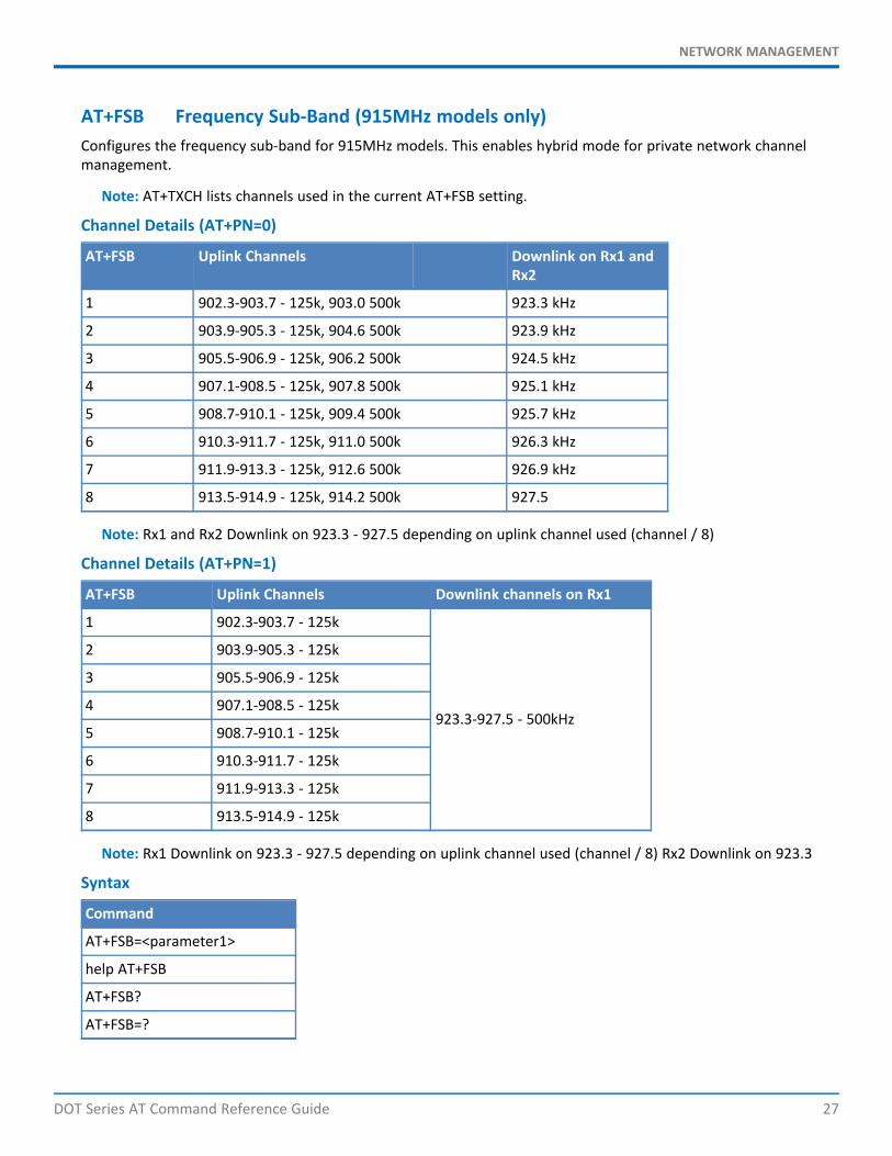
AT+FSB Frequency Sub-Band (915MHz models only)Configures the frequency sub-band for 915MHz models. This enables hybrid mode for private network channelmanagement.
Note: AT+TXCH lists channels used in the current AT+FSB setting.
Channel Details (AT+PN=0)
AT+FSB Uplink Channels Downlink on Rx1 andRx2
1 902.3-903.7 - 125k, 903.0 500k 923.3 kHz
2 903.9-905.3 - 125k, 904.6 500k 923.9 kHz
3 905.5-906.9 - 125k, 906.2 500k 924.5 kHz
4 907.1-908.5 - 125k, 907.8 500k 925.1 kHz
5 908.7-910.1 - 125k, 909.4 500k 925.7 kHz
6 910.3-911.7 - 125k, 911.0 500k 926.3 kHz
7 911.9-913.3 - 125k, 912.6 500k 926.9 kHz
8 913.5-914.9 - 125k, 914.2 500k 927.5
Note: Rx1 and Rx2 Downlink on 923.3 - 927.5 depending on uplink channel used (channel / 8)
Channel Details (AT+PN=1)
AT+FSB Uplink Channels Downlink channels on Rx1
1 902.3-903.7 - 125k
923.3-927.5 - 500kHz
2 903.9-905.3 - 125k
3 905.5-906.9 - 125k
4 907.1-908.5 - 125k
5 908.7-910.1 - 125k
6 910.3-911.7 - 125k
7 911.9-913.3 - 125k
8 913.5-914.9 - 125k
Note: Rx1 Downlink on 923.3 - 927.5 depending on uplink channel used (channel / 8) Rx2 Downlink on 923.3
Syntax
Command
AT+FSB=<parameter1>
help AT+FSB
AT+FSB?
AT+FSB=?
NETWORK MANAGEMENT
28 DOT Series AT Command Reference Guide
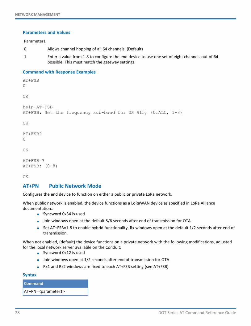
Parameters and Values
Parameter1
0 Allows channel hopping of all 64 channels. (Default)
1 Enter a value from 1-8 to configure the end device to use one set of eight channels out of 64possible. This must match the gateway settings.
Command with Response Examples
AT+FSB0
OK
help AT+FSBAT+FSB: Set the frequency sub-band for US 915, (0:ALL, 1-8)
OK
AT+FSB?0
OK
AT+FSB=?AT+FSB: (0-8)
OK
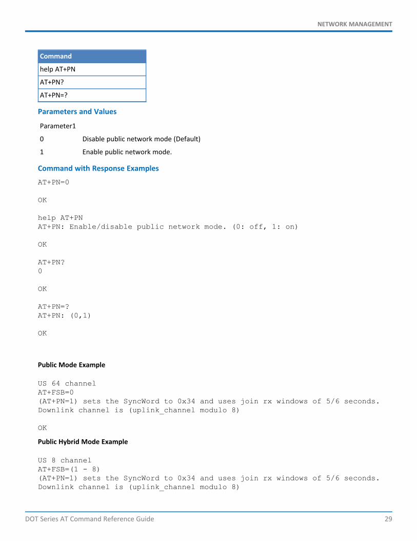
AT+PN Public Network ModeConfigures the end device to function on either a public or private LoRa network.
When public network is enabled, the device functions as a LoRaWAN device as specified in LoRa Alliancedocumentation.:
Syncword 0x34 is usedJoin windows open at the default 5/6 seconds after end of transmission for OTASet AT+FSB=1-8 to enable hybrid functionality, Rx windows open at the default 1/2 seconds after end oftransmission.
When not enabled, (default) the device functions on a private network with the following modifications, adjustedfor the local network server available on the Conduit:
Syncword 0x12 is usedJoin windows open at 1/2 seconds after end of transmission for OTARx1 and Rx2 windows are fixed to each AT+FSB setting (see AT+FSB)
Syntax
Command
AT+PN=<parameter1>
NETWORK MANAGEMENT
DOT Series AT Command Reference Guide 29
Command
help AT+PN
AT+PN?
AT+PN=?
Parameters and Values
Parameter1
0 Disable public network mode (Default)
1 Enable public network mode.
Command with Response Examples
AT+PN=0
OK
help AT+PNAT+PN: Enable/disable public network mode. (0: off, 1: on)
OK
AT+PN?0
OK
AT+PN=?AT+PN: (0,1)
OK
Public Mode Example
US 64 channelAT+FSB=0(AT+PN=1) sets the SyncWord to 0x34 and uses join rx windows of 5/6 seconds.Downlink channel is (uplink_channel modulo 8)
OK
Public Hybrid Mode Example
US 8 channelAT+FSB=(1 - 8)(AT+PN=1) sets the SyncWord to 0x34 and uses join rx windows of 5/6 seconds.Downlink channel is (uplink_channel modulo 8)
NETWORK MANAGEMENT
30 DOT Series AT Command Reference Guide
OK
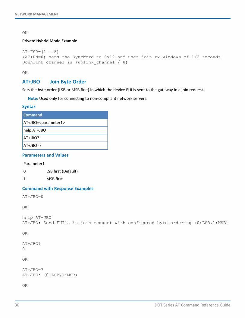
Private Hybrid Mode Example
AT+FSB=(1 - 8)(AT+PN=0) sets the SyncWord to 0x12 and uses join rx windows of 1/2 seconds.Downlink channel is (uplink_channel / 8)
OK
AT+JBO Join Byte OrderSets the byte order (LSB or MSB first) in which the device EUI is sent to the gateway in a join request.
Note: Used only for connecting to non-compliant network servers.
Syntax
Command
AT+JBO=<parameter1>
help AT+JBO
AT+JBO?
AT+JBO=?
Parameters and Values
Parameter1
0 LSB first (Default)
1 MSB first
Command with Response Examples
AT+JBO=0
OK
help AT+JBOAT+JBO: Send EUI's in join request with configured byte ordering (0:LSB,1:MSB)
OK
AT+JBO?0
OK
AT+JBO=?AT+JBO: (0:LSB,1:MSB)
OK
NETWORK MANAGEMENT
DOT Series AT Command Reference Guide 31
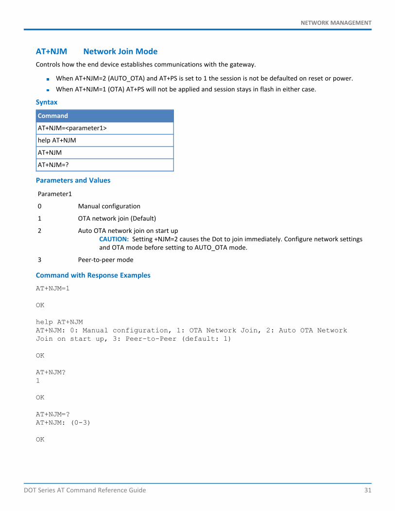
AT+NJM Network Join ModeControls how the end device establishes communications with the gateway.
When AT+NJM=2 (AUTO_OTA) and AT+PS is set to 1 the session is not be defaulted on reset or power.When AT+NJM=1 (OTA) AT+PS will not be applied and session stays in flash in either case.
Syntax
Command
AT+NJM=<parameter1>
help AT+NJM
AT+NJM
AT+NJM=?
Parameters and Values
Parameter1
0 Manual configuration
1 OTA network join (Default)
2 Auto OTA network join on start upCAUTION: Setting +NJM=2 causes the Dot to join immediately. Configure network settingsand OTA mode before setting to AUTO_OTA mode.
3 Peer-to-peer mode
Command with Response Examples
AT+NJM=1
OK
help AT+NJMAT+NJM: 0: Manual configuration, 1: OTA Network Join, 2: Auto OTA NetworkJoin on start up, 3: Peer-to-Peer (default: 1)
OK
AT+NJM?1
OK
AT+NJM=?AT+NJM: (0-3)
OK
NETWORK MANAGEMENT
32 DOT Series AT Command Reference Guide
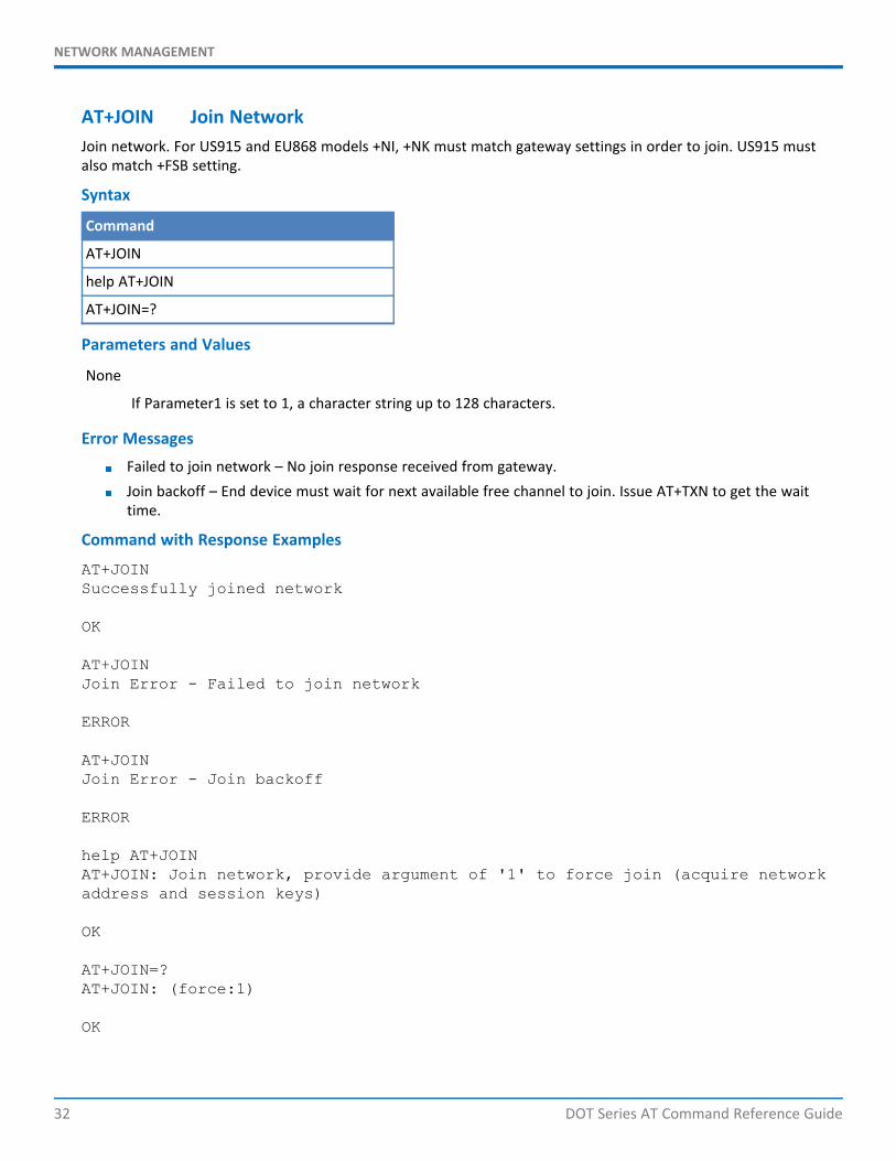
AT+JOIN Join NetworkJoin network. For US915 and EU868 models +NI, +NK must match gateway settings in order to join. US915 mustalso match +FSB setting.
Syntax
Command
AT+JOIN
help AT+JOIN
AT+JOIN=?
Parameters and Values
None
If Parameter1 is set to 1, a character string up to 128 characters.
Error MessagesFailed to join network – No join response received from gateway.Join backoff – End device must wait for next available free channel to join. Issue AT+TXN to get the waittime.
Command with Response Examples
AT+JOINSuccessfully joined network
OK
AT+JOINJoin Error - Failed to join network
ERROR
AT+JOINJoin Error - Join backoff
ERROR
help AT+JOINAT+JOIN: Join network, provide argument of '1' to force join (acquire networkaddress and session keys)
OK
AT+JOIN=?AT+JOIN: (force:1)
OK
NETWORK MANAGEMENT
DOT Series AT Command Reference Guide 33
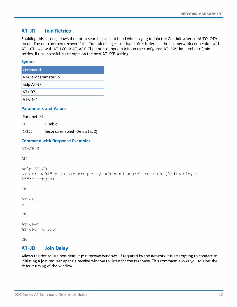
AT+JR Join RetriesEnabling this setting allows the dot to search each sub-band when trying to join the Conduit when in AUTO_OTAmode. The dot can then recover if the Conduit changes sub-band after it detects the lost network connection withAT+LCT used with AT+LCC or AT+ACK. The dot attempts to join on the configured AT+FSB the number of joinretries, if unsuccessful it attempts on the next AT+FSB setting.
Syntax
Command
AT+JR=<parameter1>
help AT+JR
AT+JR?
AT+JR=?
Parameters and Values
Parameter1
0 Disable
1-255 Seconds enabled (Default is 2)
Command with Response Examples
AT+JR=5
OK
help AT+JRAT+JR: US915 AUTO_OTA Frequency sub-band search retries (0:disable,1-255:attempts)
OK
AT+JR?5
OK
AT+JR=?AT+JR: (0-255)
OK
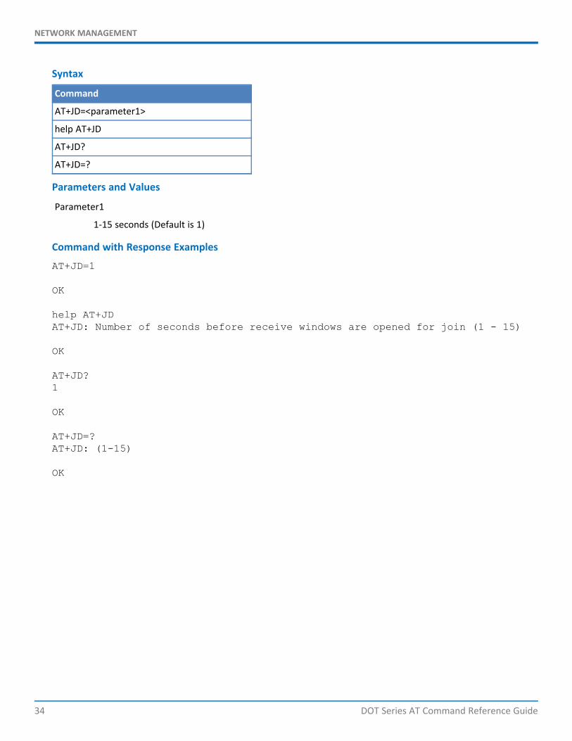
AT+JD Join DelayAllows the dot to use non-default join receive windows, if required by the network it is attempting to connect to.Initiating a join request opens a receive window to listen for the response. This command allows you to alter thedefault timing of the window.
NETWORK MANAGEMENT
34 DOT Series AT Command Reference Guide
Syntax
Command
AT+JD=<parameter1>
help AT+JD
AT+JD?
AT+JD=?
Parameters and Values
Parameter1
1-15 seconds (Default is 1)
Command with Response Examples
AT+JD=1
OK
help AT+JDAT+JD: Number of seconds before receive windows are opened for join (1 - 15)
OK
AT+JD?1
OK
AT+JD=?AT+JD: (1-15)
OK
NETWORK MANAGEMENT
DOT Series AT Command Reference Guide 35
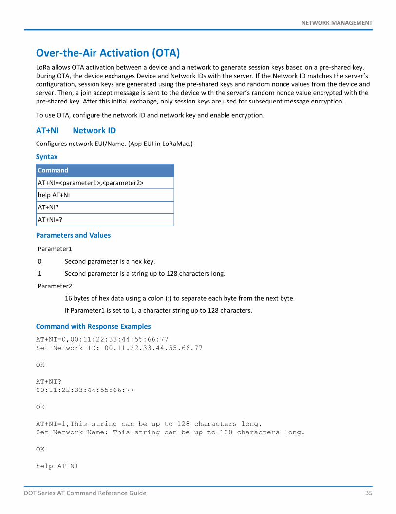
Over-the-Air Activation (OTA)LoRa allows OTA activation between a device and a network to generate session keys based on a pre-shared key.During OTA, the device exchanges Device and Network IDs with the server. If the Network ID matches the server’sconfiguration, session keys are generated using the pre-shared keys and random nonce values from the device andserver. Then, a join accept message is sent to the device with the server’s random nonce value encrypted with thepre-shared key. After this initial exchange, only session keys are used for subsequent message encryption.
To use OTA, configure the network ID and network key and enable encryption.
AT+NI Network IDConfigures network EUI/Name. (App EUI in LoRaMac.)
Syntax
Command
AT+NI=<parameter1>,<parameter2>
help AT+NI
AT+NI?
AT+NI=?
Parameters and Values
Parameter1
0 Second parameter is a hex key.
1 Second parameter is a string up to 128 characters long.
Parameter2
16 bytes of hex data using a colon (:) to separate each byte from the next byte.
If Parameter1 is set to 1, a character string up to 128 characters.
Command with Response Examples
AT+NI=0,00:11:22:33:44:55:66:77Set Network ID: 00.11.22.33.44.55.66.77
OK
AT+NI?00:11:22:33:44:55:66:77
OK
AT+NI=1,This string can be up to 128 characters long.Set Network Name: This string can be up to 128 characters long.
OK
help AT+NI
NETWORK MANAGEMENT
36 DOT Series AT Command Reference Guide
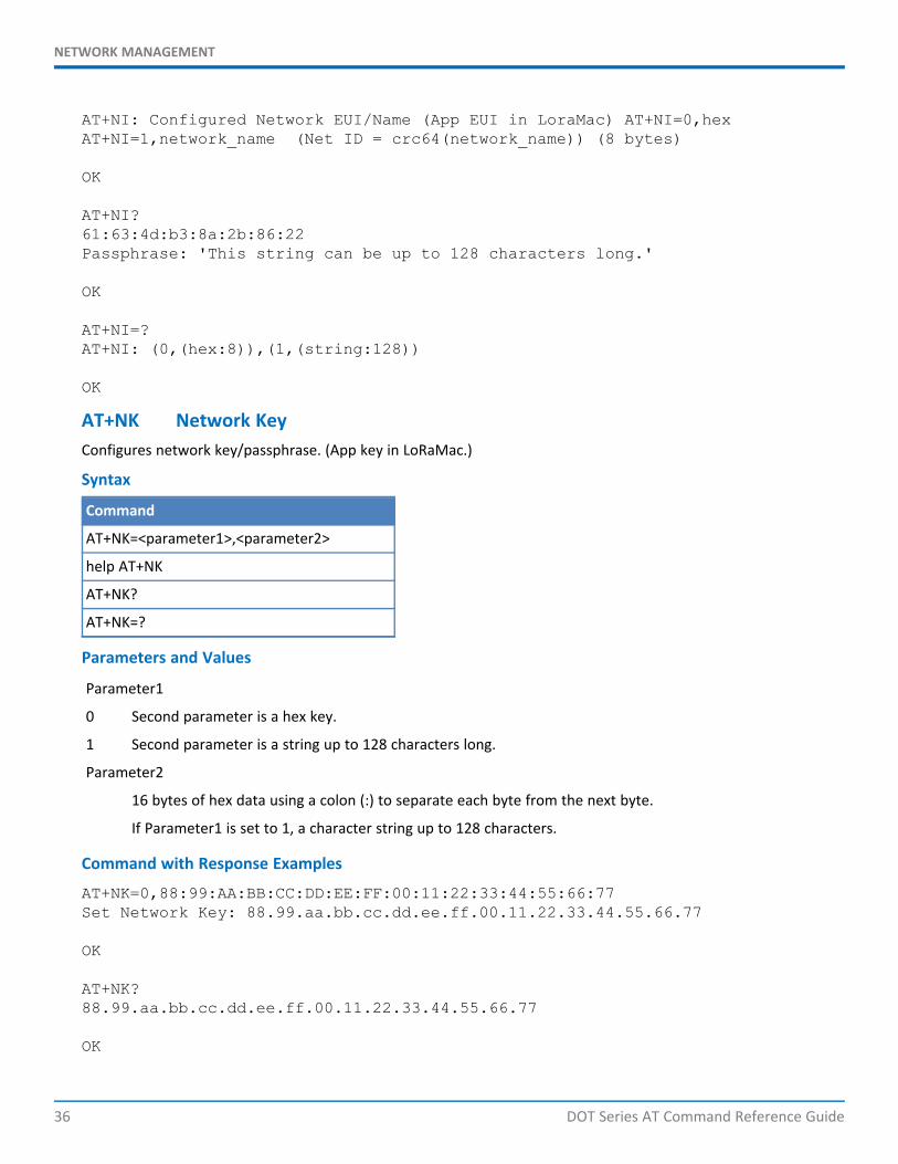
AT+NI: Configured Network EUI/Name (App EUI in LoraMac) AT+NI=0,hexAT+NI=1,network_name (Net ID = crc64(network_name)) (8 bytes)
OK
AT+NI?61:63:4d:b3:8a:2b:86:22Passphrase: 'This string can be up to 128 characters long.'
OK
AT+NI=?AT+NI: (0,(hex:8)),(1,(string:128))
OK
AT+NK Network KeyConfigures network key/passphrase. (App key in LoRaMac.)
Syntax
Command
AT+NK=<parameter1>,<parameter2>
help AT+NK
AT+NK?
AT+NK=?
Parameters and Values
Parameter1
0 Second parameter is a hex key.
1 Second parameter is a string up to 128 characters long.
Parameter2
16 bytes of hex data using a colon (:) to separate each byte from the next byte.
If Parameter1 is set to 1, a character string up to 128 characters.
Command with Response Examples
AT+NK=0,88:99:AA:BB:CC:DD:EE:FF:00:11:22:33:44:55:66:77Set Network Key: 88.99.aa.bb.cc.dd.ee.ff.00.11.22.33.44.55.66.77
OK
AT+NK?88.99.aa.bb.cc.dd.ee.ff.00.11.22.33.44.55.66.77
OK

NETWORK MANAGEMENT
DOT Series AT Command Reference Guide 37
AT+NK=1,This String can be up to 128 characters long.Set Network Passphrase: This String can be up to 128 characters long.
OK
help AT+NKAT+NK: Configured network key/passphrase (App Key in LoraMac) ## AT+NK=0,hexAT+NK=1,passphrase (Net key = cmac(passphrase)) (16 bytes)
OK
AT+NK?e1.07.15.95.06.50.46.80.89.cf.2e.6e.2b.ea.f9.cfPassphrase: 'This String can be up to 128 characters long.'
OK
AT+NK=?AT+NK: (0,(hex:16)),(1,(string:128))
OK
AT+ENC AES EncryptionEnables or disables AES encryption of payload data.
Note: Must be enabled for use with nearly all network servers."
Syntax
Command
AT+ENC=<parameter1>
help AT+ENC
AT+ENC?
AT+ENC=?
Parameters and Values
Parameter1
0 Disabled
1 Enabled (Default)
Command with Response Examples
AT+ENC=1
OK
help AT+ENCAT+ENC: Enable/disable AES encryption (0: off, 1: on)
NETWORK MANAGEMENT
38 DOT Series AT Command Reference Guide
OK
AT+ENC?1
OK
AT+ENC=?AT+ENC: (0,1)
OK
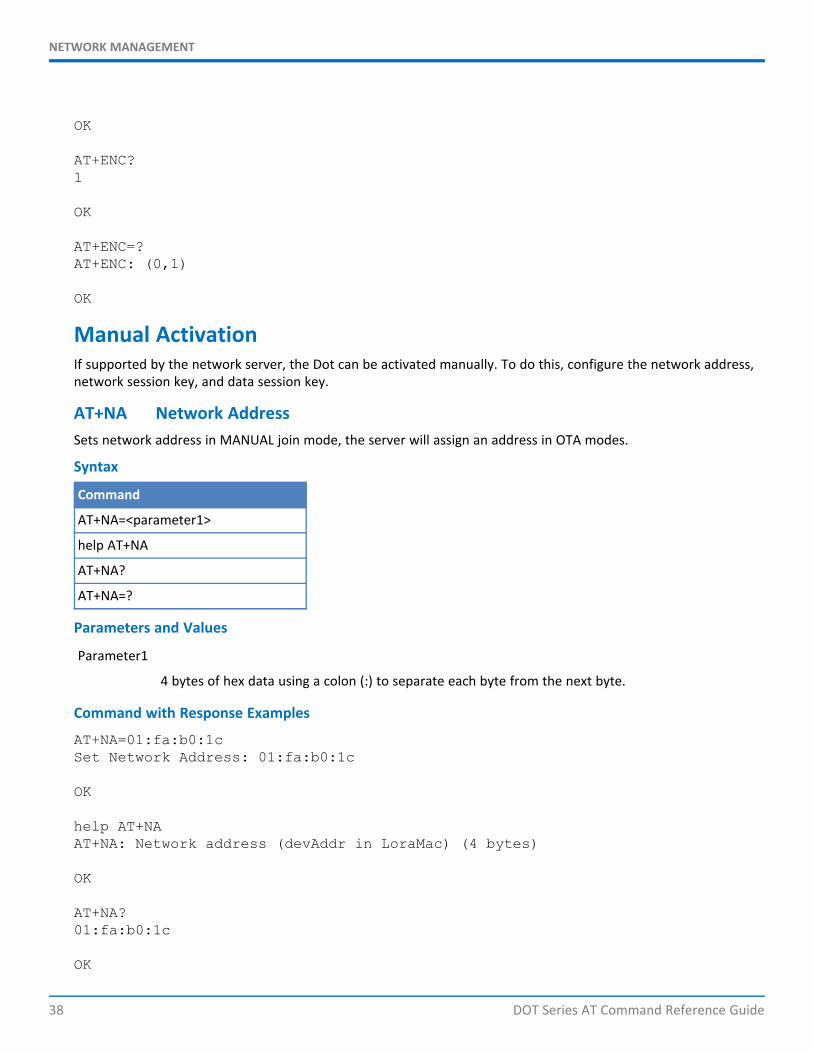
Manual ActivationIf supported by the network server, the Dot can be activated manually. To do this, configure the network address,network session key, and data session key.
AT+NA Network AddressSets network address in MANUAL join mode, the server will assign an address in OTA modes.
Syntax
Command
AT+NA=<parameter1>
help AT+NA
AT+NA?
AT+NA=?
Parameters and Values
Parameter1
4 bytes of hex data using a colon (:) to separate each byte from the next byte.
Command with Response Examples
AT+NA=01:fa:b0:1cSet Network Address: 01:fa:b0:1c
OK
help AT+NAAT+NA: Network address (devAddr in LoraMac) (4 bytes)
OK
AT+NA?01:fa:b0:1c
OK
NETWORK MANAGEMENT
DOT Series AT Command Reference Guide 39
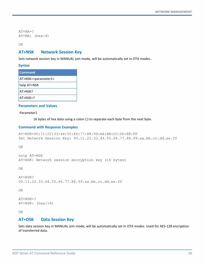
AT+NA=?AT+NA: (hex:4)
OK
AT+NSK Network Session KeySets network session key in MANUAL join mode, will be automatically set in OTA modes..
Syntax
Command
AT+NSK=<parameter1>
help AT+NSK
AT+NSK?
AT+NSK=?
Parameters and Values
Parameter1
16 bytes of hex data using a colon (:) to separate each byte from the next byte.
Command with Response Examples
AT+NSK=00:11:22:33:44:55:66:77:88:99:AA:BB:CC:DD:EE:FFSet Network Session Key: 00.11.22.33.44.55.66.77.88.99.aa.bb.cc.dd.ee.ff
OK
help AT+NSKAT+NSK: Network session encryption key (16 bytes)
OK
AT+NSK?00.11.22.33.44.55.66.77.88.99.aa.bb.cc.dd.ee.ff
OK
AT+NSK=?AT+NSK: (hex:16)
OK
AT+DSK Data Session KeySets data session key in MANUAL join mode, will be automatically set in OTA modes. Used for AES-128 encryptionof transferred data.

NETWORK MANAGEMENT
40 DOT Series AT Command Reference Guide
Syntax
Command
AT+DSK=<parameter1>
help AT+DSK
AT+DSK?
AT+DSK=?
Parameters and Values
Parameter1
16 bytes of hex data using a colon (:) to separate each byte from the next byte.
Command with Response Examples
AT+DSK=FF:EE:DD:CC:BB:AA:99:88:77:66:55:44:33:22:11:00Set Data Session Key: ff.ee.dd.cc.bb.aa.99.88.77.66.55.44.33.22.11.00
OK
help AT+DSKAT+DSK: Data session encryption key (16 bytes)
OK
AT+DSK?ff.ee.dd.cc.bb.aa.99.88.77.66.55.44.33.22.11.00
OK
AT+DSK=?AT+DSK: (hex:16)
OK
AT+ULC Uplink CounterA device using MANUAL join mode a network server may reject uplink packets, if they do not have the correctcounter value. This setting is available for an application to manage this session parameter. Otherwise, use AT+SSand AT+RS to save this setting to flash in any join mode.
Syntax
Command
AT+ULC=<parameter1>
help AT+ULC
AT+ULC?
AT+ULC=?
NETWORK MANAGEMENT
DOT Series AT Command Reference Guide 41
Parameters and Values
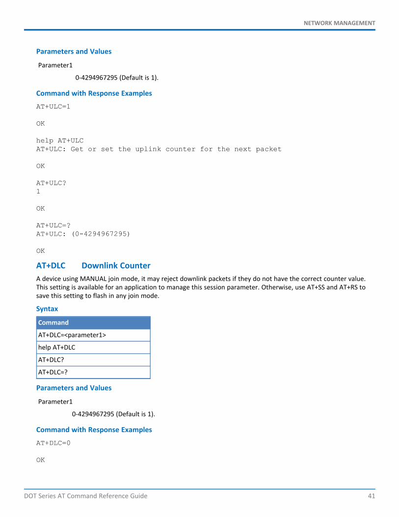
Parameter1
0-4294967295 (Default is 1).
Command with Response Examples
AT+ULC=1
OK
help AT+ULCAT+ULC: Get or set the uplink counter for the next packet
OK
AT+ULC?1
OK
AT+ULC=?AT+ULC: (0-4294967295)
OK
AT+DLC Downlink CounterA device using MANUAL join mode, it may reject downlink packets if they do not have the correct counter value.This setting is available for an application to manage this session parameter. Otherwise, use AT+SS and AT+RS tosave this setting to flash in any join mode.
Syntax
Command
AT+DLC=<parameter1>
help AT+DLC
AT+DLC?
AT+DLC=?
Parameters and Values
Parameter1
0-4294967295 (Default is 1).
Command with Response Examples
AT+DLC=0
OK
NETWORK MANAGEMENT
42 DOT Series AT Command Reference Guide
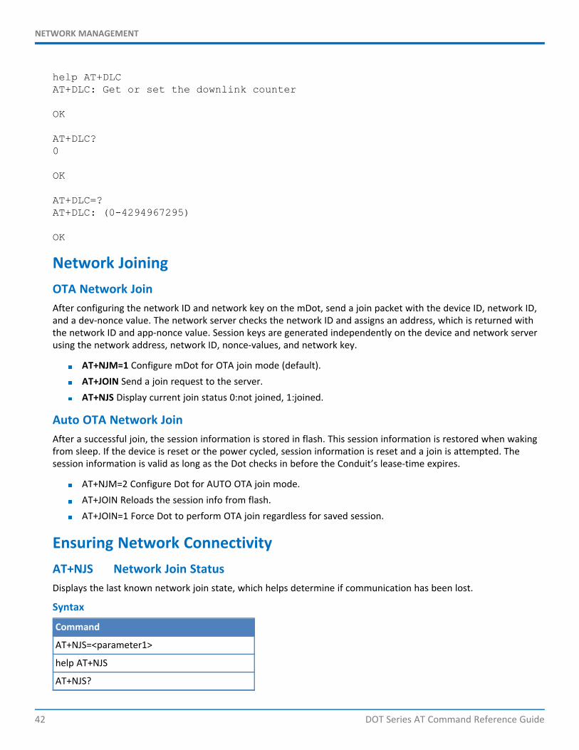
help AT+DLCAT+DLC: Get or set the downlink counter
OK
AT+DLC?0
OK
AT+DLC=?AT+DLC: (0-4294967295)
OK
Network JoiningOTA Network JoinAfter configuring the network ID and network key on the mDot, send a join packet with the device ID, network ID,and a dev-nonce value. The network server checks the network ID and assigns an address, which is returned withthe network ID and app-nonce value. Session keys are generated independently on the device and network serverusing the network address, network ID, nonce-values, and network key.
AT+NJM=1 Configure mDot for OTA join mode (default).AT+JOIN Send a join request to the server.AT+NJS Display current join status 0:not joined, 1:joined.
Auto OTA Network JoinAfter a successful join, the session information is stored in flash. This session information is restored when wakingfrom sleep. If the device is reset or the power cycled, session information is reset and a join is attempted. Thesession information is valid as long as the Dot checks in before the Conduit’s lease-time expires.
AT+NJM=2 Configure Dot for AUTO OTA join mode.AT+JOIN Reloads the session info from flash.AT+JOIN=1 Force Dot to perform OTA join regardless for saved session.
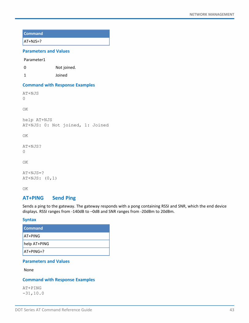
Ensuring Network ConnectivityAT+NJS Network Join StatusDisplays the last known network join state, which helps determine if communication has been lost.
Syntax
Command
AT+NJS=<parameter1>
help AT+NJS
AT+NJS?
NETWORK MANAGEMENT
DOT Series AT Command Reference Guide 43
Command
AT+NJS=?
Parameters and Values
Parameter1
0 Not joined.
1 Joined
Command with Response Examples
AT+NJS0
OK
help AT+NJSAT+NJS: 0: Not joined, 1: Joined
OK
AT+NJS?0
OK
AT+NJS=?AT+NJS: (0,1)
OK
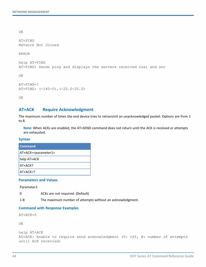
AT+PING Send PingSends a ping to the gateway. The gateway responds with a pong containing RSSI and SNR, which the end devicedisplays. RSSI ranges from -140dB to –0dB and SNR ranges from -20dBm to 20dBm.
Syntax
Command
AT+PING
help AT+PING
AT+PING=?
Parameters and Values
None
Command with Response Examples
AT+PING-31,10.0
NETWORK MANAGEMENT
44 DOT Series AT Command Reference Guide
OK
AT+PINGNetwork Not Joined
ERROR
help AT+PINGAT+PING: Sends ping and displays the servers received rssi and snr
OK
AT+PING=?AT+PING: (-140-0),(-20.0-20.0)
OK
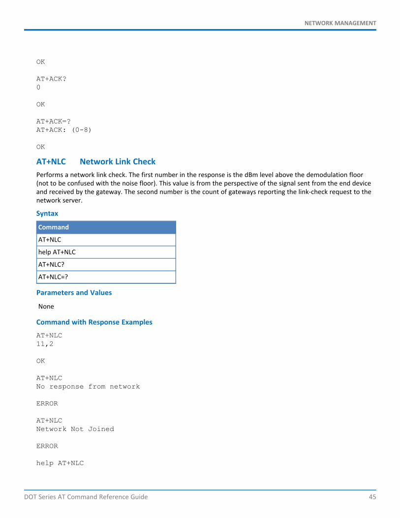
AT+ACK Require AcknowledgmentThe maximum number of times the end device tries to retransmit an unacknowledged packet. Options are from 1to 8.
Note: When ACKs are enabled, the AT+SEND command does not return until the ACK is received or attemptsare exhausted.
Syntax
Command
AT+ACK=<parameter1>
help AT+ACK
AT+ACK?
AT+ACK=?
Parameters and Values
Parameter1
0 ACKs are not required. (Default)
1-8 The maximum number of attempts without an acknowledgment.
Command with Response Examples
AT+ACK=0
OK
help AT+ACKAT+ACK: Enable to require send acknowledgment (0: off, N: number of attemptsuntil ACK recevied)
NETWORK MANAGEMENT
DOT Series AT Command Reference Guide 45
OK
AT+ACK?0
OK
AT+ACK=?AT+ACK: (0-8)
OK
AT+NLC Network Link CheckPerforms a network link check. The first number in the response is the dBm level above the demodulation floor(not to be confused with the noise floor). This value is from the perspective of the signal sent from the end deviceand received by the gateway. The second number is the count of gateways reporting the link-check request to thenetwork server.
Syntax
Command
AT+NLC
help AT+NLC
AT+NLC?
AT+NLC=?
Parameters and Values
None
Command with Response Examples
AT+NLC11,2
OK
AT+NLCNo response from network
ERROR
AT+NLCNetwork Not Joined
ERROR
help AT+NLC
NETWORK MANAGEMENT
46 DOT Series AT Command Reference Guide
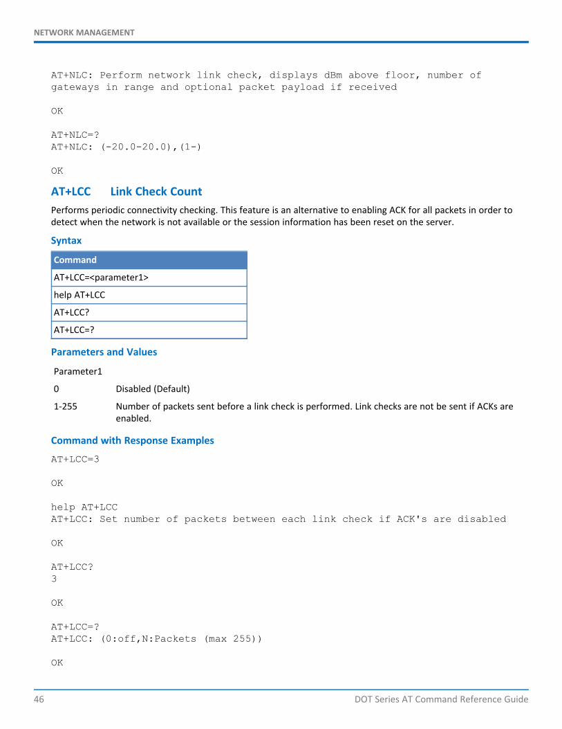
AT+NLC: Perform network link check, displays dBm above floor, number ofgateways in range and optional packet payload if received
OK
AT+NLC=?AT+NLC: (-20.0-20.0),(1-)
OK
AT+LCC Link Check CountPerforms periodic connectivity checking. This feature is an alternative to enabling ACK for all packets in order todetect when the network is not available or the session information has been reset on the server.
Syntax
Command
AT+LCC=<parameter1>
help AT+LCC
AT+LCC?
AT+LCC=?
Parameters and Values
Parameter1
0 Disabled (Default)
1-255 Number of packets sent before a link check is performed. Link checks are not be sent if ACKs areenabled.
Command with Response Examples
AT+LCC=3
OK
help AT+LCCAT+LCC: Set number of packets between each link check if ACK's are disabled
OK
AT+LCC?3
OK
AT+LCC=?AT+LCC: (0:off,N:Packets (max 255))
OK
NETWORK MANAGEMENT
DOT Series AT Command Reference Guide 47
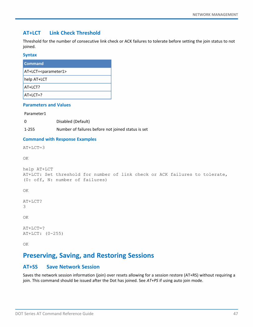
AT+LCT Link Check ThresholdThreshold for the number of consecutive link check or ACK failures to tolerate before setting the join status to notjoined.
Syntax
Command
AT+LCT=<parameter1>
help AT+LCT
AT+LCT?
AT+LCT=?
Parameters and Values
Parameter1
0 Disabled (Default)
1-255 Number of failures before not joined status is set
Command with Response Examples
AT+LCT=3
OK
help AT+LCTAT+LCT: Set threshold for number of link check or ACK failures to tolerate,(0: off, N: number of failures)
OK
AT+LCT?3
OK
AT+LCT=?AT+LCT: (0-255)
OK
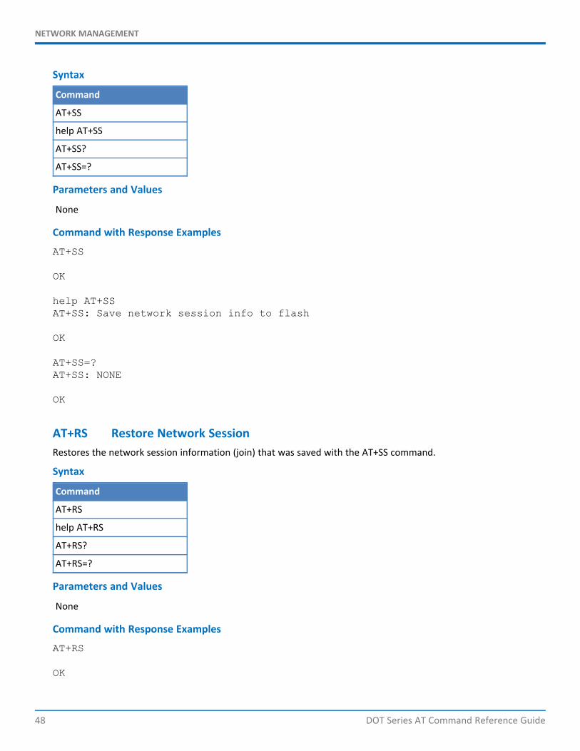
Preserving, Saving, and Restoring SessionsAT+SS Save Network SessionSaves the network session information (join) over resets allowing for a session restore (AT+RS) without requiring ajoin. This command should be issued after the Dot has joined. See AT+PS if using auto join mode.
NETWORK MANAGEMENT
48 DOT Series AT Command Reference Guide
Syntax
Command
AT+SS
help AT+SS
AT+SS?
AT+SS=?
Parameters and Values
None
Command with Response Examples
AT+SS
OK
help AT+SSAT+SS: Save network session info to flash
OK
AT+SS=?AT+SS: NONE
OK
AT+RS Restore Network SessionRestores the network session information (join) that was saved with the AT+SS command.
Syntax
Command
AT+RS
help AT+RS
AT+RS?
AT+RS=?
Parameters and Values
None
Command with Response Examples
AT+RS
OK

NETWORK MANAGEMENT
DOT Series AT Command Reference Guide 49
HELP AT+RSAT+RS: Restore network session info from flash
OK
AT+RS=?AT+RS: NONE
OK
AT+PS Preserve SessionPreserves the network session information over resets when using auto join mode (AT+NJM). If not using auto joinmode, use with the save session command (AT+SS).
Syntax
Command
AT+PS=<parameter1>
help AT+PS
AT+PS?
AT+PS=?
Parameters and Values
Parameter1
0 Off (Default)
1 On
Command with Response Examples
AT+PS=0
OK
help AT+PSAT+PS: Save network session info through reset or power down in AUTO_OTA mode(0:off, 1:on)
OK
AT+PS?0
OK
AT+PS=?AT+PS: (0,1)
OK
SENDING AND RECEIVING PACKETS
50 DOT Series AT Command Reference Guide
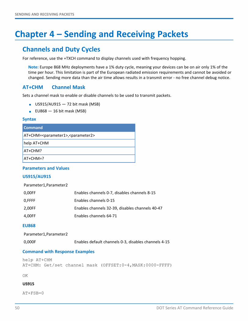
Chapter 4 – Sending and Receiving PacketsChannels and Duty CyclesFor reference, use the +TXCH command to display channels used with frequency hopping.
Note: Europe 868 MHz deployments have a 1% duty cycle, meaning your devices can be on air only 1% of thetime per hour. This limitation is part of the European radiated emission requirements and cannot be avoided orchanged. Sending more data than the air time allows results in a transmit error - no free channel debug notice.
AT+CHM Channel MaskSets a channel mask to enable or disable channels to be used to transmit packets.
US915/AU915 — 72 bit mask (MSB)EU868 — 16 bit mask (MSB)
Syntax
Command
AT+CHM=<parameter1>,<parameter2>
help AT+CHM
AT+CHM?
AT+CHM=?
Parameters and Values
US915/AU915
Parameter1,Parameter2
0,00FF Enables channels 0-7, disables channels 8-15
0,FFFF Enables channels 0-15
2,00FF Enables channels 32-39, disables channels 40-47
4,00FF Enables channels 64-71
EU868
Parameter1,Parameter2
0,000F Enables default channels 0-3, disables channels 4-15
Command with Response Examples
help AT+CHMAT+CHM: Get/set channel mask (OFFSET:0-4,MASK:0000-FFFF)
OK
US915
AT+FSB=0
SENDING AND RECEIVING PACKETS
DOT Series AT Command Reference Guide 51
OK
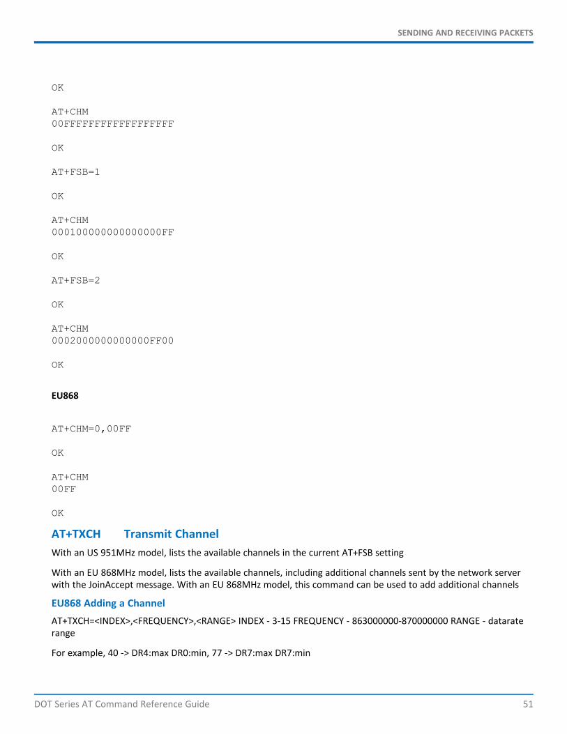
AT+CHM00FFFFFFFFFFFFFFFFFF
OK
AT+FSB=1
OK
AT+CHM000100000000000000FF
OK
AT+FSB=2
OK
AT+CHM0002000000000000FF00
OK
EU868
AT+CHM=0,00FF
OK
AT+CHM00FF
OK
AT+TXCH Transmit ChannelWith an US 951MHz model, lists the available channels in the current AT+FSB setting
With an EU 868MHz model, lists the available channels, including additional channels sent by the network serverwith the JoinAccept message. With an EU 868MHz model, this command can be used to add additional channels
EU868 Adding a ChannelAT+TXCH=<INDEX>,<FREQUENCY>,<RANGE> INDEX - 3-15 FREQUENCY - 863000000-870000000 RANGE - dataraterange
For example, 40 -> DR4:max DR0:min, 77 -> DR7:max DR7:min

SENDING AND RECEIVING PACKETS
52 DOT Series AT Command Reference Guide
Syntax
Command
AT+TXCH
help AT+TXCH
AT+TXCH?
AT+TXCH=?
Parameters and Values
None
Command with Response Examples
help AT+TXCHAT+TXCH: List Tx channel frequencies for sub-band
OK
AT+FSB=1
OK
AT+TXCHIndex Frequency DR Max Min On0 902300000 3 0 11 902500000 3 0 12 902700000 3 0 13 902900000 3 0 14 903100000 3 0 15 903300000 3 0 16 903500000 3 0 17 903700000 3 0 1U 903000000 4 4 1R2 923300000 8 8
OK
OK
AT+TXCH=?AT+TXCH: TABLE
OK
Note the following for US915:
U : Uplink Channel for DR4:SF8BW500R2 : Frequency and datarate for second receive windowIn public mode, R2 defaults to 923.3 DR8
SENDING AND RECEIVING PACKETS
DOT Series AT Command Reference Guide 53
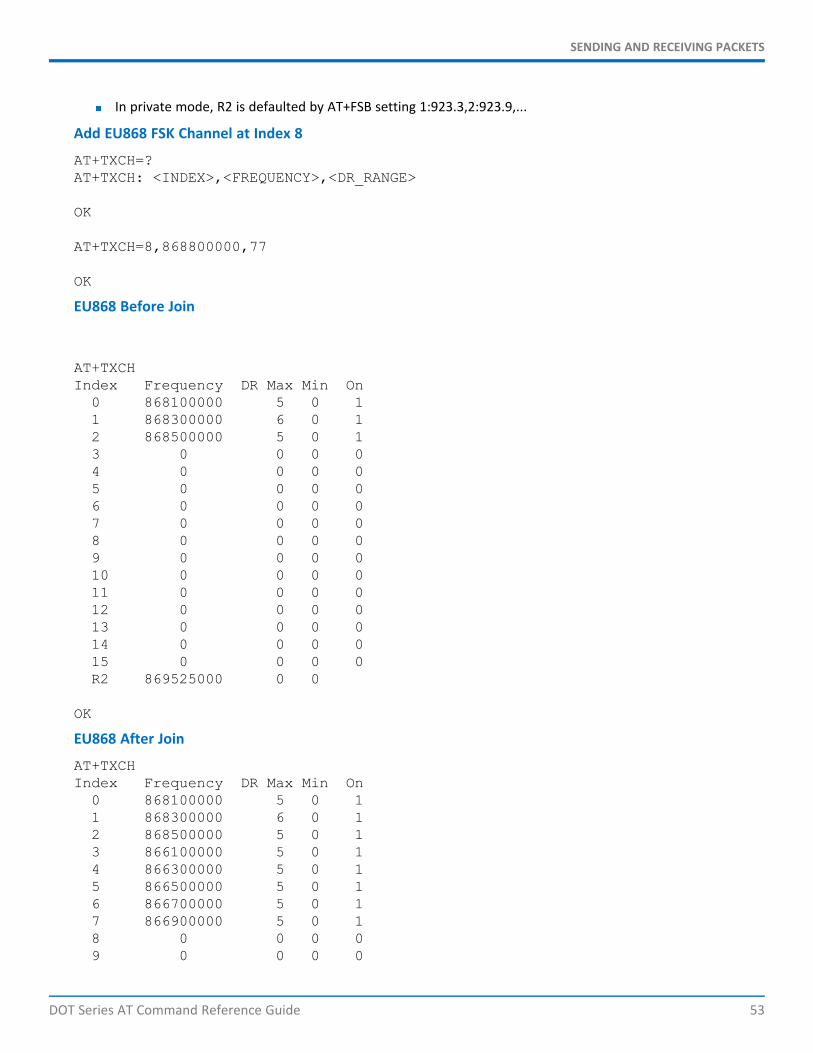
In private mode, R2 is defaulted by AT+FSB setting 1:923.3,2:923.9,...
Add EU868 FSK Channel at Index 8
AT+TXCH=?AT+TXCH: <INDEX>,<FREQUENCY>,<DR_RANGE>
OK
AT+TXCH=8,868800000,77
OK
EU868 Before Join
AT+TXCHIndex Frequency DR Max Min On0 868100000 5 0 11 868300000 6 0 12 868500000 5 0 13 0 0 0 04 0 0 0 05 0 0 0 06 0 0 0 07 0 0 0 08 0 0 0 09 0 0 0 010 0 0 0 011 0 0 0 012 0 0 0 013 0 0 0 014 0 0 0 015 0 0 0 0R2 869525000 0 0
OK
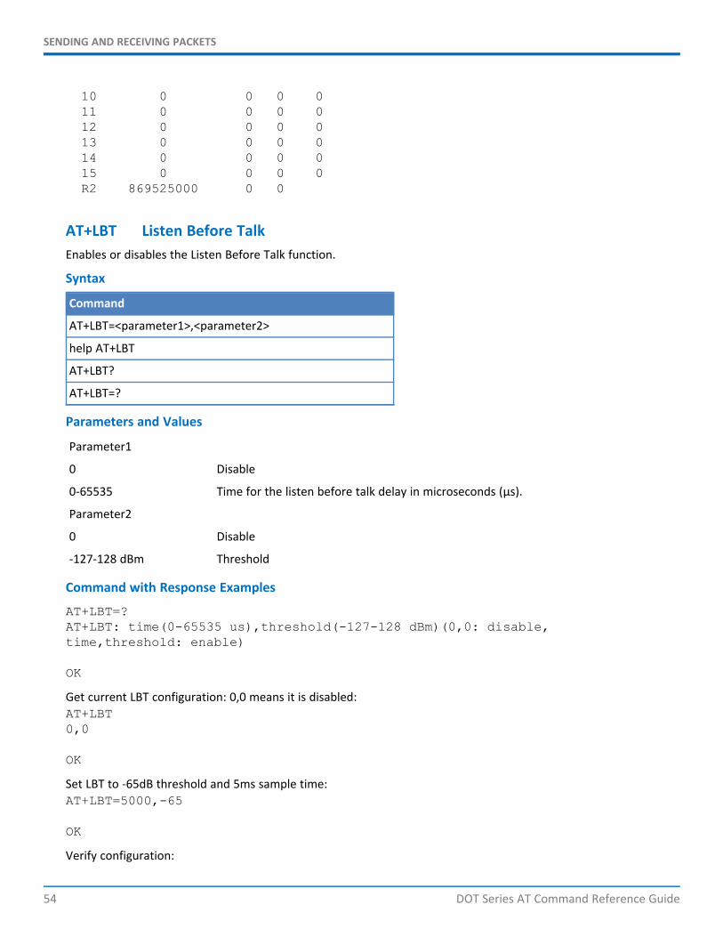
EU868 After Join
AT+TXCHIndex Frequency DR Max Min On0 868100000 5 0 11 868300000 6 0 12 868500000 5 0 13 866100000 5 0 14 866300000 5 0 15 866500000 5 0 16 866700000 5 0 17 866900000 5 0 18 0 0 0 09 0 0 0 0
SENDING AND RECEIVING PACKETS
54 DOT Series AT Command Reference Guide
10 0 0 0 011 0 0 0 012 0 0 0 013 0 0 0 014 0 0 0 015 0 0 0 0R2 869525000 0 0
AT+LBT Listen Before TalkEnables or disables the Listen Before Talk function.
Syntax
Command
AT+LBT=<parameter1>,<parameter2>
help AT+LBT
AT+LBT?
AT+LBT=?
Parameters and Values
Parameter1
0 Disable
0-65535 Time for the listen before talk delay in microseconds (μs).
Parameter2
0 Disable
-127-128 dBm Threshold
Command with Response Examples
AT+LBT=?AT+LBT: time(0-65535 us),threshold(-127-128 dBm)(0,0: disable,time,threshold: enable)
OK
Get current LBT configuration: 0,0 means it is disabled:AT+LBT0,0
OK
Set LBT to -65dB threshold and 5ms sample time:AT+LBT=5000,-65
OK
Verify configuration:
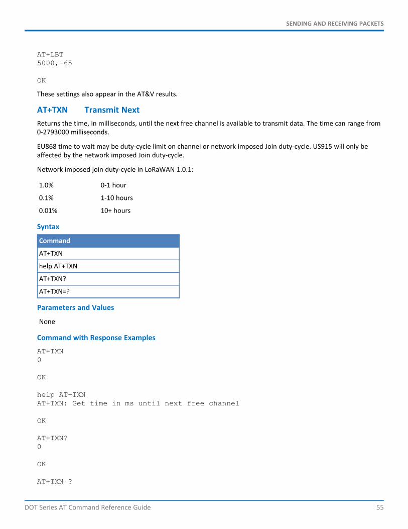
SENDING AND RECEIVING PACKETS
DOT Series AT Command Reference Guide 55
AT+LBT5000,-65
OK
These settings also appear in the AT&V results.
AT+TXN Transmit NextReturns the time, in milliseconds, until the next free channel is available to transmit data. The time can range from0-2793000 milliseconds.
EU868 time to wait may be duty-cycle limit on channel or network imposed Join duty-cycle. US915 will only beaffected by the network imposed Join duty-cycle.
Network imposed join duty-cycle in LoRaWAN 1.0.1:
1.0% 0-1 hour
0.1% 1-10 hours
0.01% 10+ hours
Syntax
Command
AT+TXN
help AT+TXN
AT+TXN?
AT+TXN=?
Parameters and Values
None
Command with Response Examples
AT+TXN0
OK
help AT+TXNAT+TXN: Get time in ms until next free channel
OK
AT+TXN?0
OK
AT+TXN=?

SENDING AND RECEIVING PACKETS
56 DOT Series AT Command Reference Guide
AT+TXN: (0-2793000)
OK
AT+TOA Time On AirDisplays the amount of on air time, in milliseconds, required to transmit the number of bytes specified at thecurrent data rate. (Included for informational purposes. )
Syntax
Command
AT+TOA=<parameter1>
help AT+TOA
AT+TOA?
AT+TOA=?
Parameters and Values
Parameter1
0-242 The number of bytes used to calculate the time on air.
Command with Response Examples
AT+TOA=128738
OK
help AT+TOAAT+TOA: Get time in ms of packet tx with current datarate
OK
AT+TOA?Invalid parameter, expects (0-242)
ERROR
AT+TOA=?AT+TOA: (0-242)
OK
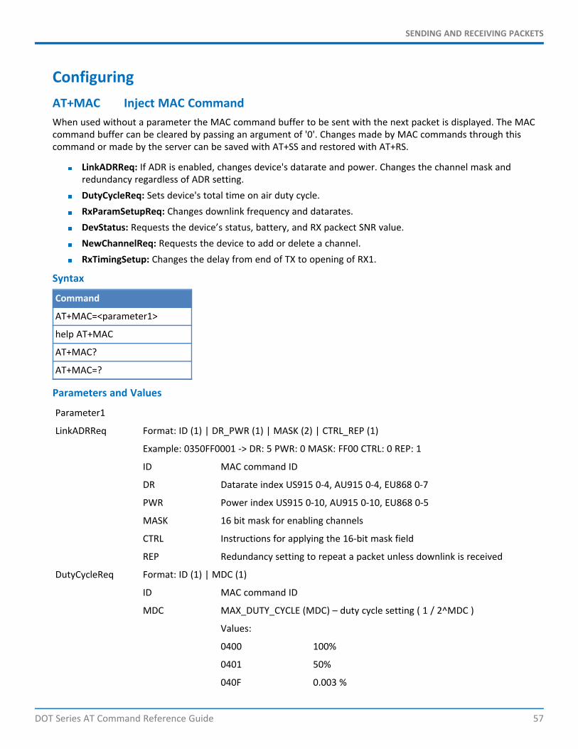
SENDING AND RECEIVING PACKETS
DOT Series AT Command Reference Guide 57
ConfiguringAT+MAC Inject MAC CommandWhen used without a parameter the MAC command buffer to be sent with the next packet is displayed. The MACcommand buffer can be cleared by passing an argument of '0'. Changes made by MAC commands through thiscommand or made by the server can be saved with AT+SS and restored with AT+RS.
LinkADRReq: If ADR is enabled, changes device's datarate and power. Changes the channel mask andredundancy regardless of ADR setting.DutyCycleReq: Sets device's total time on air duty cycle.RxParamSetupReq: Changes downlink frequency and datarates.DevStatus: Requests the device’s status, battery, and RX packect SNR value.NewChannelReq: Requests the device to add or delete a channel.RxTimingSetup: Changes the delay from end of TX to opening of RX1.
Syntax
Command
AT+MAC=<parameter1>
help AT+MAC
AT+MAC?
AT+MAC=?
Parameters and Values
Parameter1
LinkADRReq Format: ID (1) | DR_PWR (1) | MASK (2) | CTRL_REP (1)
Example: 0350FF0001 -> DR: 5 PWR: 0 MASK: FF00 CTRL: 0 REP: 1
ID MAC command ID
DR Datarate index US915 0-4, AU915 0-4, EU868 0-7
PWR Power index US915 0-10, AU915 0-10, EU868 0-5
MASK 16 bit mask for enabling channels
CTRL Instructions for applying the 16-bit mask field
REP Redundancy setting to repeat a packet unless downlink is received
DutyCycleReq Format: ID (1) | MDC (1)
ID MAC command ID
MDC MAX_DUTY_CYCLE (MDC) – duty cycle setting ( 1 / 2^MDC )
Values:
0400 100%
0401 50%
040F 0.003 %

SENDING AND RECEIVING PACKETS
58 DOT Series AT Command Reference Guide
RxParamSetupReq Format: ID (1) | DLSettings (1) | Frequency (3)
Example: 050468E28C ? RX1O: 0 RX2: 5 FREQ: 923300000
ID MAC command ID
DLSettings Datarate offset for RX1 and datarate index for RX2
Frequency 3 bytes of frequency in 100 Hz (LSB)
DevStatus Format: ID (1)
Example: 06
ID MAC command ID
NewChannelReq Note: EU868 only, Channels 0-2 cannot be changed.Format: ID (1) | INDEX (1) | FREQ (3) | RANGE (1)
Example: 0703F87D8440 -> INDEX: 3 FREQ: 868300000 RANGE: MAX:4 MIN:0
ID MAC command ID
INDEX Channel Index
FREQ Channel frequency in 100 Hz
RANGE Datarate range (MAX:4,MIN:4)
RxTimingSetup Format: ID (1) | DELAY (1)
Example: 0801 ? DELAY: 1 second
ID MAC command ID
Delay Delay in seconds until RX1
Command with Response ExamplesInject Device Status MAC Command
AT+MAC=06
OK
Show MAC Commands Buffer to be Sent in Next Packet
AT+MAC06ff00
OK
Clear MAC Commands Buffer to be Sent in Next Packet
AT+MAC=0
OK
AT+MAC
OK
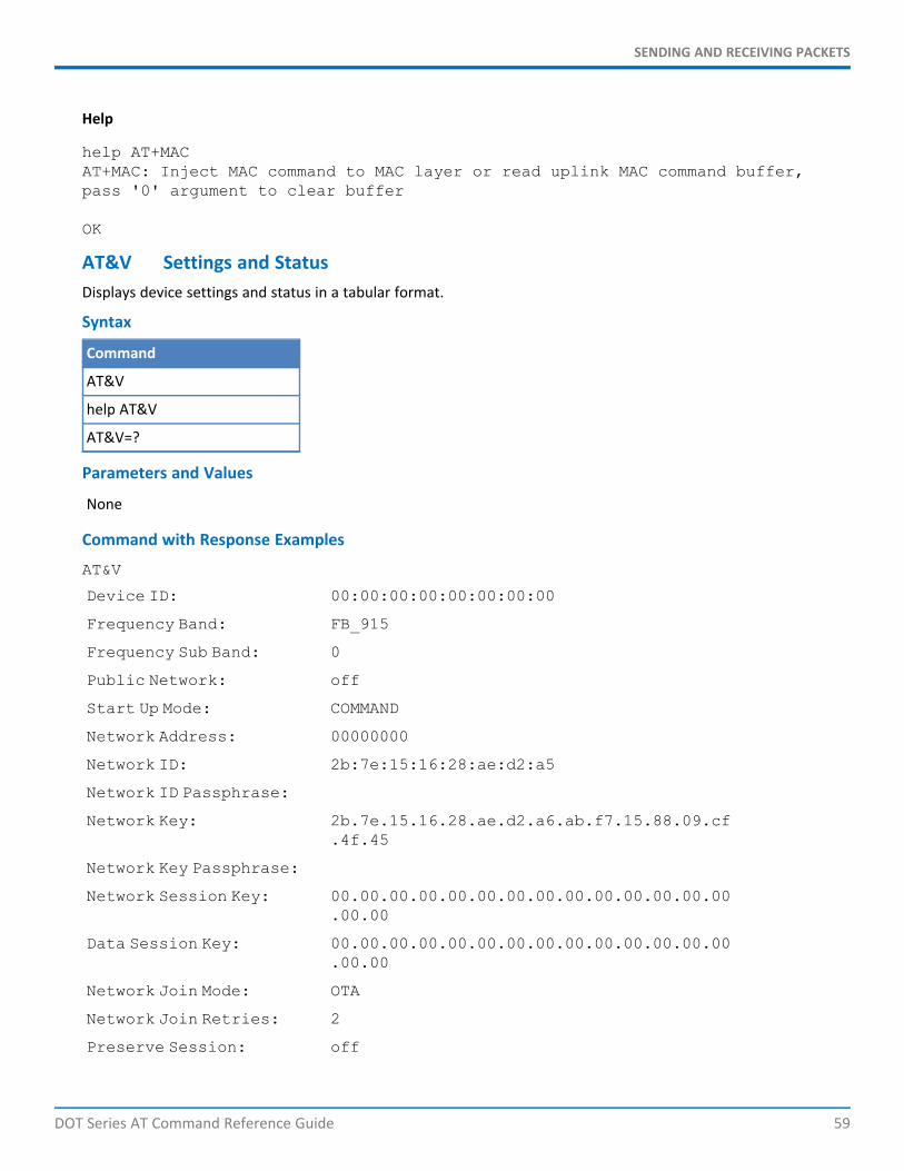
SENDING AND RECEIVING PACKETS
DOT Series AT Command Reference Guide 59
Help
help AT+MACAT+MAC: Inject MAC command to MAC layer or read uplink MAC command buffer,pass '0' argument to clear buffer
OK
AT&V Settings and StatusDisplays device settings and status in a tabular format.
Syntax
Command
AT&V
help AT&V
AT&V=?
Parameters and Values
None
Command with Response Examples
AT&V
Device ID: 00:00:00:00:00:00:00:00
Frequency Band: FB_915
Frequency Sub Band: 0
Public Network: off
Start Up Mode: COMMAND
Network Address: 00000000
Network ID: 2b:7e:15:16:28:ae:d2:a5
Network ID Passphrase:
Network Key: 2b.7e.15.16.28.ae.d2.a6.ab.f7.15.88.09.cf.4f.45
Network Key Passphrase:
Network Session Key: 00.00.00.00.00.00.00.00.00.00.00.00.00.00.00.00
Data Session Key: 00.00.00.00.00.00.00.00.00.00.00.00.00.00.00.00
Network Join Mode: OTA
Network Join Retries: 2
Preserve Session: off

SENDING AND RECEIVING PACKETS
60 DOT Series AT Command Reference Guide
Join Byte Order: LSB
Join Delay: 1
App Port: 1
Link Check Threshold: off
Link Check Count: off
Error Correction: 1 bytes
ACK Retries: off
Packet Repeat: 1
Encryption: on
CRC: on
Adaptive Data Rate: off
Command Echo: on
Verbose Response: off
Tx Frequency: 0
Tx Data Rate: DR0 - SF10BW125
Tx Power: 11
Tx Antenna Gain: 3
Tx Wait: on
Tx Inverted Signal: off
Rx Delay: 1 s
Rx Inverted Signal: on
Rx Output Style: HEXADECIMAL
Debug Baud Rate: 115200
Serial Baud Rate: 115200
Serial Flow Control: off
Serial Clear On Error: on
Wake Mode: INTERVAL
Wake Interval: 10 s
Wake Delay: 100 ms
Wake Timeout: 20 ms
Wake Pin: DI8
Log Level: 0
OK
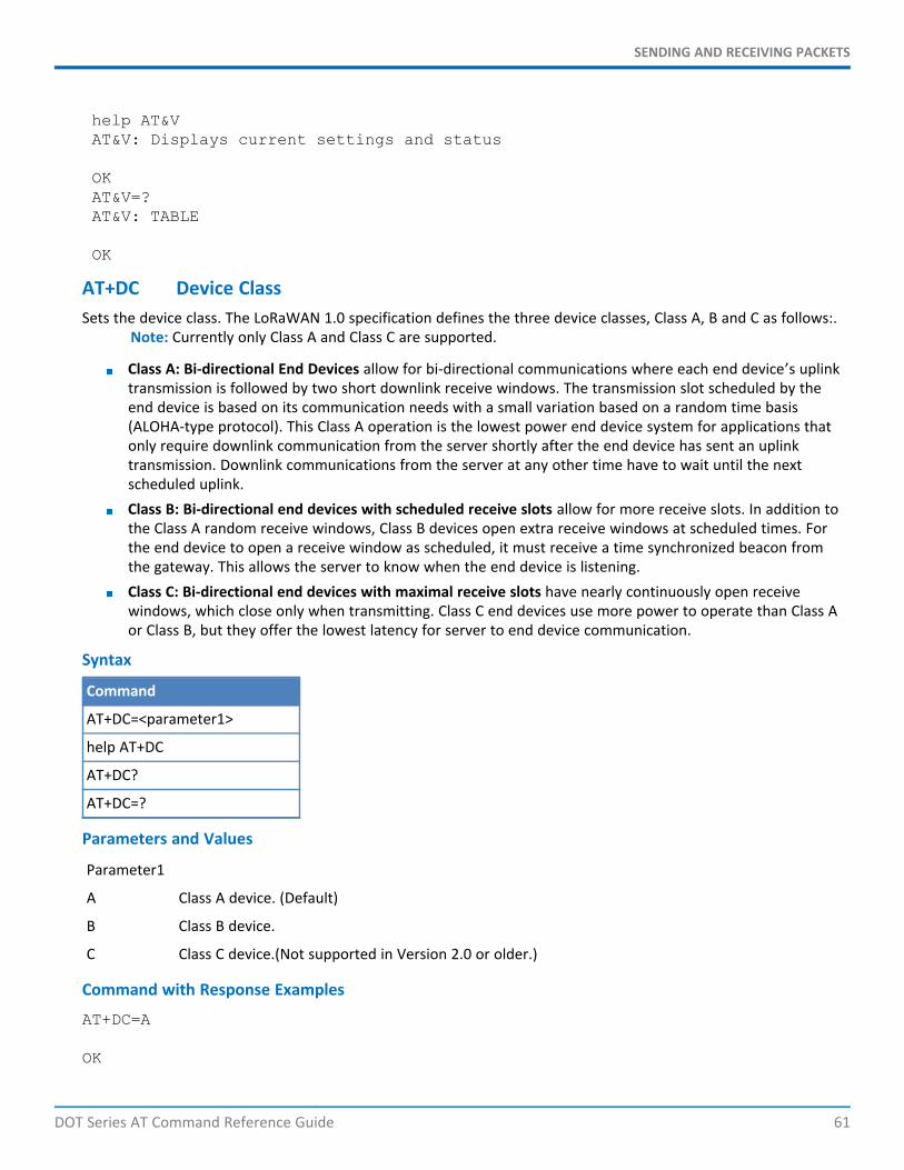
SENDING AND RECEIVING PACKETS
DOT Series AT Command Reference Guide 61
help AT&VAT&V: Displays current settings and status
OKAT&V=?AT&V: TABLE
OK
AT+DC Device ClassSets the device class. The LoRaWAN 1.0 specification defines the three device classes, Class A, B and C as follows:.
Note: Currently only Class A and Class C are supported.
Class A: Bi-directional End Devices allow for bi-directional communications where each end device’s uplinktransmission is followed by two short downlink receive windows. The transmission slot scheduled by theend device is based on its communication needs with a small variation based on a random time basis(ALOHA-type protocol). This Class A operation is the lowest power end device system for applications thatonly require downlink communication from the server shortly after the end device has sent an uplinktransmission. Downlink communications from the server at any other time have to wait until the nextscheduled uplink.Class B: Bi-directional end devices with scheduled receive slots allow for more receive slots. In addition tothe Class A random receive windows, Class B devices open extra receive windows at scheduled times. Forthe end device to open a receive window as scheduled, it must receive a time synchronized beacon fromthe gateway. This allows the server to know when the end device is listening.Class C: Bi-directional end devices with maximal receive slots have nearly continuously open receivewindows, which close only when transmitting. Class C end devices use more power to operate than Class Aor Class B, but they offer the lowest latency for server to end device communication.
Syntax
Command
AT+DC=<parameter1>
help AT+DC
AT+DC?
AT+DC=?
Parameters and Values
Parameter1
A Class A device. (Default)
B Class B device.
C Class C device.(Not supported in Version 2.0 or older.)
Command with Response Examples
AT+DC=A
OK
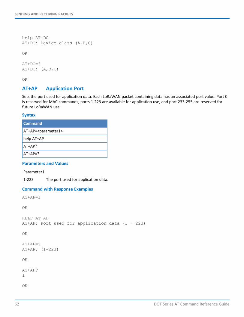
SENDING AND RECEIVING PACKETS
62 DOT Series AT Command Reference Guide
help AT+DCAT+DC: Device class (A,B,C)
OK
AT+DC=?AT+DC: (A,B,C)
OK
AT+AP Application PortSets the port used for application data. Each LoRaWAN packet containing data has an associated port value. Port 0is reserved for MAC commands, ports 1-223 are available for application use, and port 233-255 are reserved forfuture LoRaWAN use.
Syntax
Command
AT+AP=<parameter1>
help AT+AP
AT+AP?
AT+AP=?
Parameters and Values
Parameter1
1-223 The port used for application data.
Command with Response Examples
AT+AP=1
OK
HELP AT+APAT+AP: Port used for application data (1 - 223)
OK
AT+AP=?AT+AP: (1-223)
OK
AT+AP?1
OK
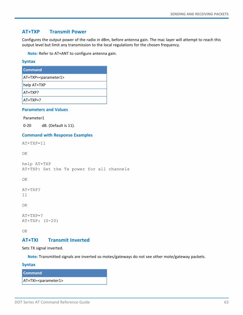
SENDING AND RECEIVING PACKETS
DOT Series AT Command Reference Guide 63
AT+TXP Transmit PowerConfigures the output power of the radio in dBm, before antenna gain. The mac layer will attempt to reach thisoutput level but limit any transmission to the local regulations for the chosen frequency.
Note: Refer to AT+ANT to configure antenna gain.
Syntax
Command
AT+TXP=<parameter1>
help AT+TXP
AT+TXP?
AT+TXP=?
Parameters and Values
Parameter1
0-20 dB. (Default is 11).
Command with Response Examples
AT+TXP=11
OK
help AT+TXPAT+TXP: Set the Tx power for all channels
OK
AT+TXP?11
OK
AT+TXP=?AT+TXP: (0-20)
OK
AT+TXI Transmit InvertedSets TX signal inverted.
Note: Transmitted signals are inverted so motes/gateways do not see other mote/gateway packets.
Syntax
Command
AT+TXI=<parameter1>
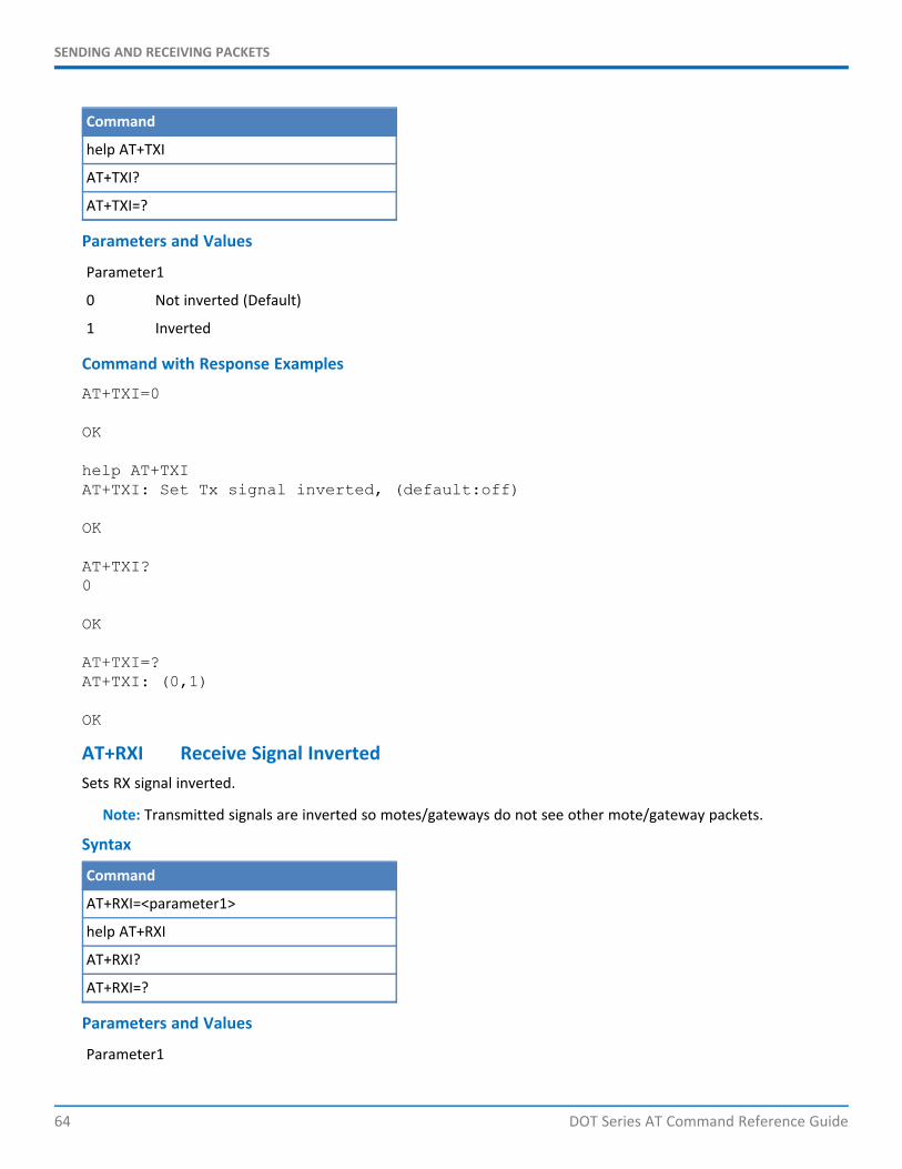
SENDING AND RECEIVING PACKETS
64 DOT Series AT Command Reference Guide
Command
help AT+TXI
AT+TXI?
AT+TXI=?
Parameters and Values
Parameter1
0 Not inverted (Default)
1 Inverted
Command with Response Examples
AT+TXI=0
OK
help AT+TXIAT+TXI: Set Tx signal inverted, (default:off)
OK
AT+TXI?0
OK
AT+TXI=?AT+TXI: (0,1)
OK
AT+RXI Receive Signal InvertedSets RX signal inverted.
Note: Transmitted signals are inverted so motes/gateways do not see other mote/gateway packets.
Syntax
Command
AT+RXI=<parameter1>
help AT+RXI
AT+RXI?
AT+RXI=?
Parameters and Values
Parameter1
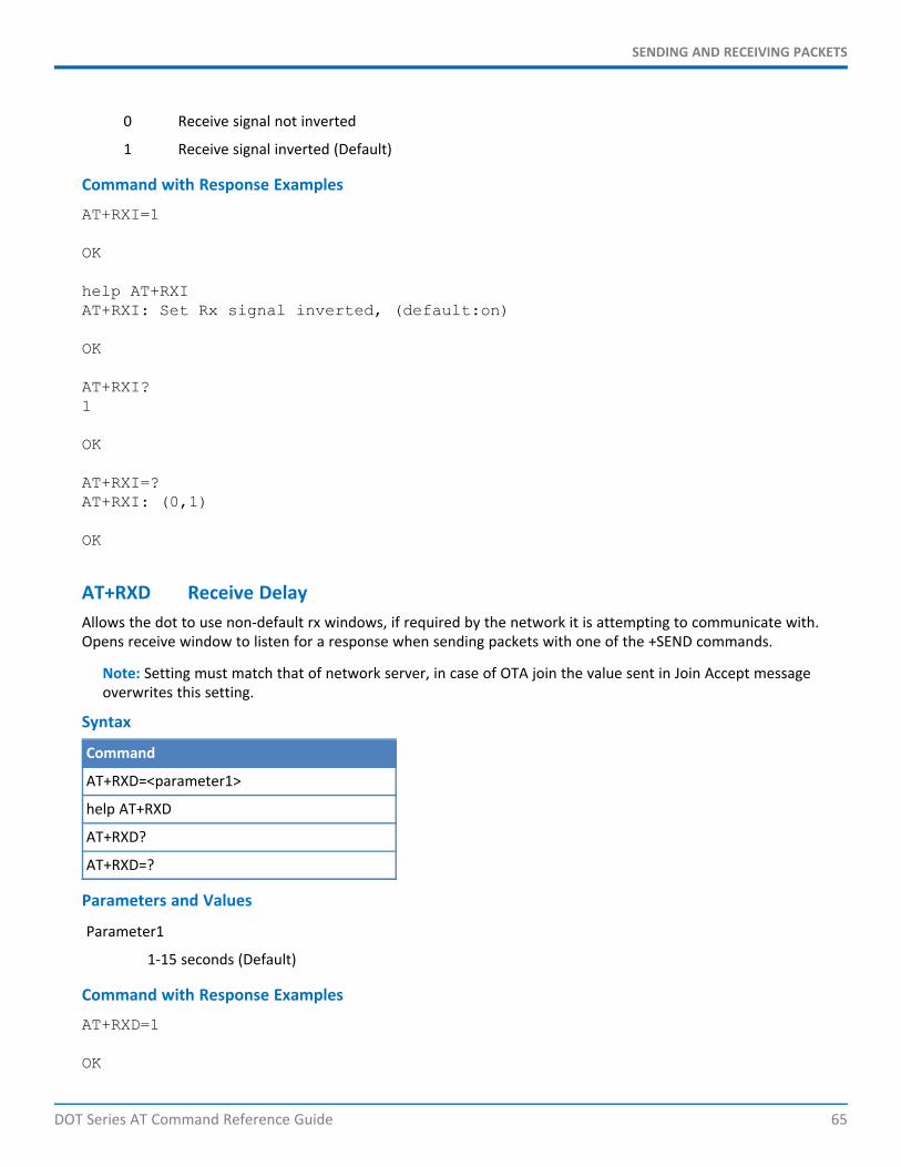
SENDING AND RECEIVING PACKETS
DOT Series AT Command Reference Guide 65
0 Receive signal not inverted
1 Receive signal inverted (Default)
Command with Response Examples
AT+RXI=1
OK
help AT+RXIAT+RXI: Set Rx signal inverted, (default:on)
OK
AT+RXI?1
OK
AT+RXI=?AT+RXI: (0,1)
OK
AT+RXD Receive DelayAllows the dot to use non-default rx windows, if required by the network it is attempting to communicate with.Opens receive window to listen for a response when sending packets with one of the +SEND commands.
Note: Setting must match that of network server, in case of OTA join the value sent in Join Accept messageoverwrites this setting.
Syntax
Command
AT+RXD=<parameter1>
help AT+RXD
AT+RXD?
AT+RXD=?
Parameters and Values
Parameter1
1-15 seconds (Default)
Command with Response Examples
AT+RXD=1
OK
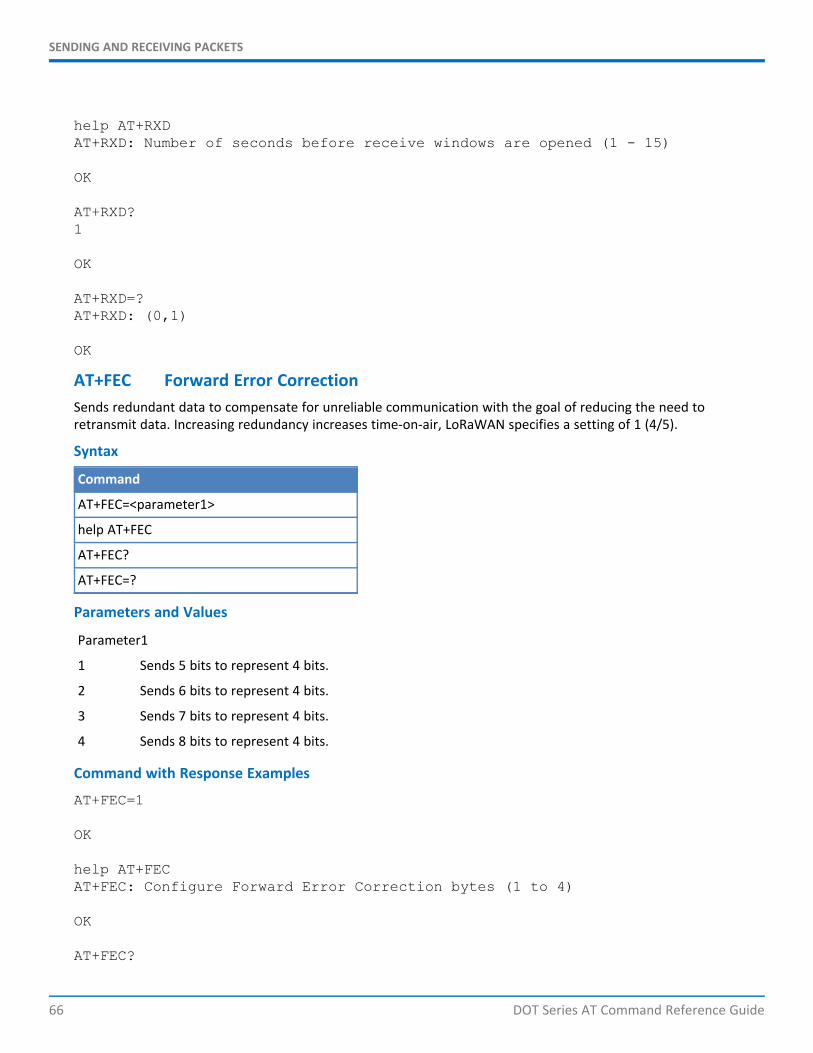
SENDING AND RECEIVING PACKETS
66 DOT Series AT Command Reference Guide
help AT+RXDAT+RXD: Number of seconds before receive windows are opened (1 - 15)
OK
AT+RXD?1
OK
AT+RXD=?AT+RXD: (0,1)
OK
AT+FEC Forward Error CorrectionSends redundant data to compensate for unreliable communication with the goal of reducing the need toretransmit data. Increasing redundancy increases time-on-air, LoRaWAN specifies a setting of 1 (4/5).
Syntax
Command
AT+FEC=<parameter1>
help AT+FEC
AT+FEC?
AT+FEC=?
Parameters and Values
Parameter1
1 Sends 5 bits to represent 4 bits.
2 Sends 6 bits to represent 4 bits.
3 Sends 7 bits to represent 4 bits.
4 Sends 8 bits to represent 4 bits.
Command with Response Examples
AT+FEC=1
OK
help AT+FECAT+FEC: Configure Forward Error Correction bytes (1 to 4)
OK
AT+FEC?
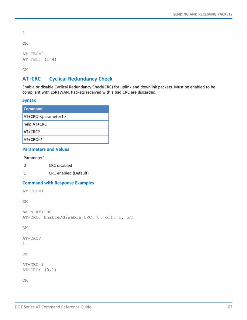
SENDING AND RECEIVING PACKETS
DOT Series AT Command Reference Guide 67
1
OK
AT+FEC=?AT+FEC: (1-4)
OK
AT+CRC Cyclical Redundancy CheckEnable or disable Cyclical Redundancy Check(CRC) for uplink and downlink packets. Must be enabled to becompliant with LoRaWAN. Packets received with a bad CRC are discarded.
Syntax
Command
AT+CRC=<parameter1>
help AT+CRC
AT+CRC?
AT+CRC=?
Parameters and Values
Parameter1
0 CRC disabled
1 CRC enabled (Default)
Command with Response Examples
AT+CRC=1
OK
help AT+CRCAT+CRC: Enable/disable CRC (0: off, 1: on)
OK
AT+CRC?1
OK
AT+CRC=?AT+CRC: (0,1)
OK
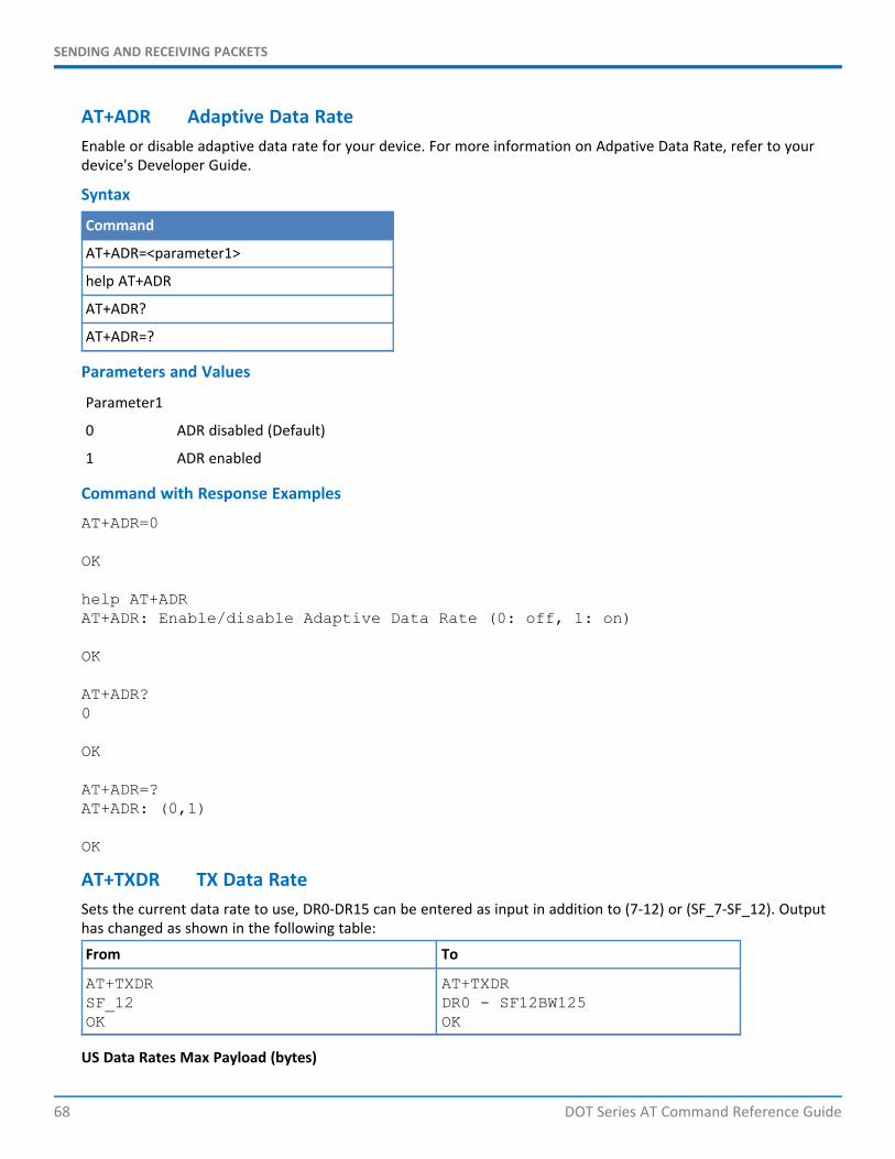
SENDING AND RECEIVING PACKETS
68 DOT Series AT Command Reference Guide
AT+ADR Adaptive Data RateEnable or disable adaptive data rate for your device. For more information on Adpative Data Rate, refer to yourdevice's Developer Guide.
Syntax
Command
AT+ADR=<parameter1>
help AT+ADR
AT+ADR?
AT+ADR=?
Parameters and Values
Parameter1
0 ADR disabled (Default)
1 ADR enabled
Command with Response Examples
AT+ADR=0
OK
help AT+ADRAT+ADR: Enable/disable Adaptive Data Rate (0: off, 1: on)
OK
AT+ADR?0
OK
AT+ADR=?AT+ADR: (0,1)
OK
AT+TXDR TX Data RateSets the current data rate to use, DR0-DR15 can be entered as input in addition to (7-12) or (SF_7-SF_12). Outputhas changed as shown in the following table:
From To
AT+TXDRSF_12OK
AT+TXDRDR0 - SF12BW125OK
US Data Rates Max Payload (bytes)
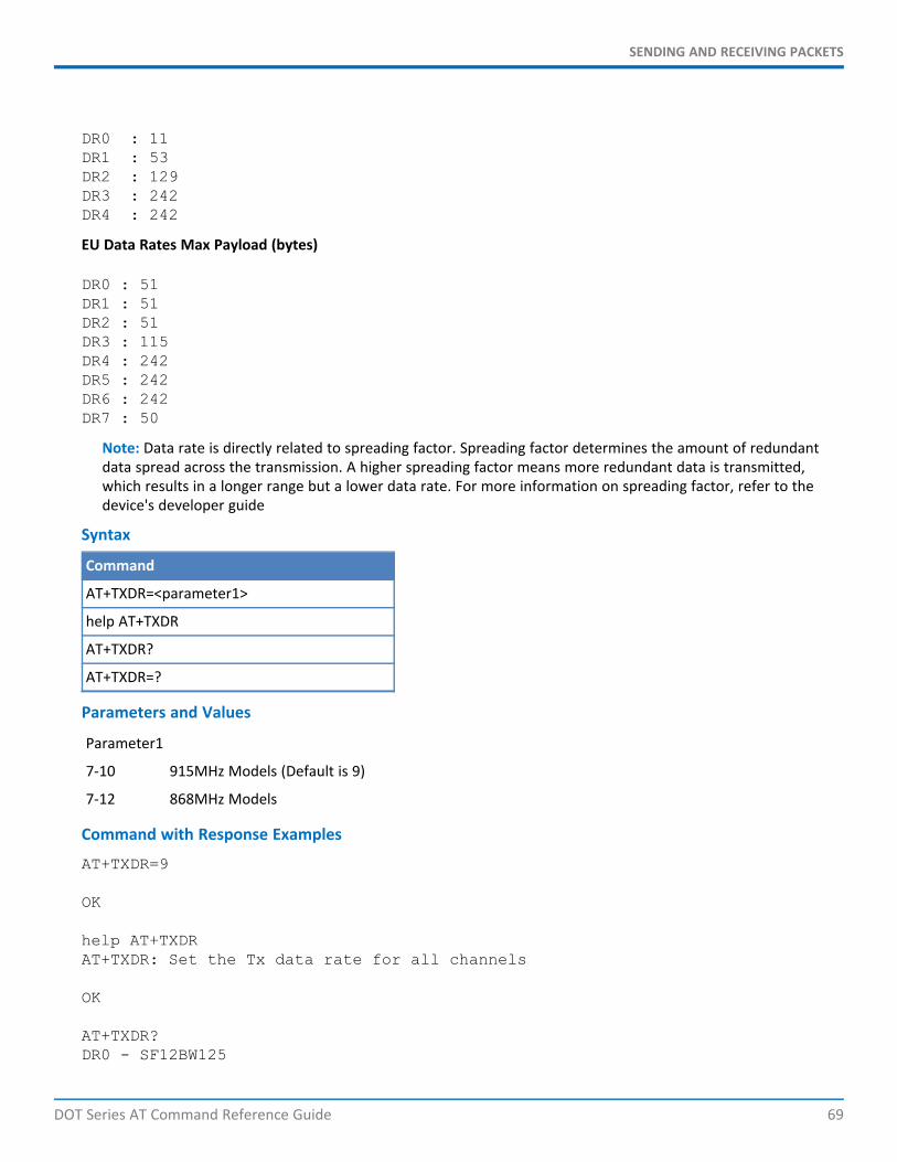
SENDING AND RECEIVING PACKETS
DOT Series AT Command Reference Guide 69
DR0 : 11DR1 : 53DR2 : 129DR3 : 242DR4 : 242
EU Data Rates Max Payload (bytes)
DR0 : 51DR1 : 51DR2 : 51DR3 : 115DR4 : 242DR5 : 242DR6 : 242DR7 : 50
Note: Data rate is directly related to spreading factor. Spreading factor determines the amount of redundantdata spread across the transmission. A higher spreading factor means more redundant data is transmitted,which results in a longer range but a lower data rate. For more information on spreading factor, refer to thedevice's developer guide
Syntax
Command
AT+TXDR=<parameter1>
help AT+TXDR
AT+TXDR?
AT+TXDR=?
Parameters and Values
Parameter1
7-10 915MHz Models (Default is 9)
7-12 868MHz Models
Command with Response Examples
AT+TXDR=9
OK
help AT+TXDRAT+TXDR: Set the Tx data rate for all channels
OK
AT+TXDR?DR0 - SF12BW125
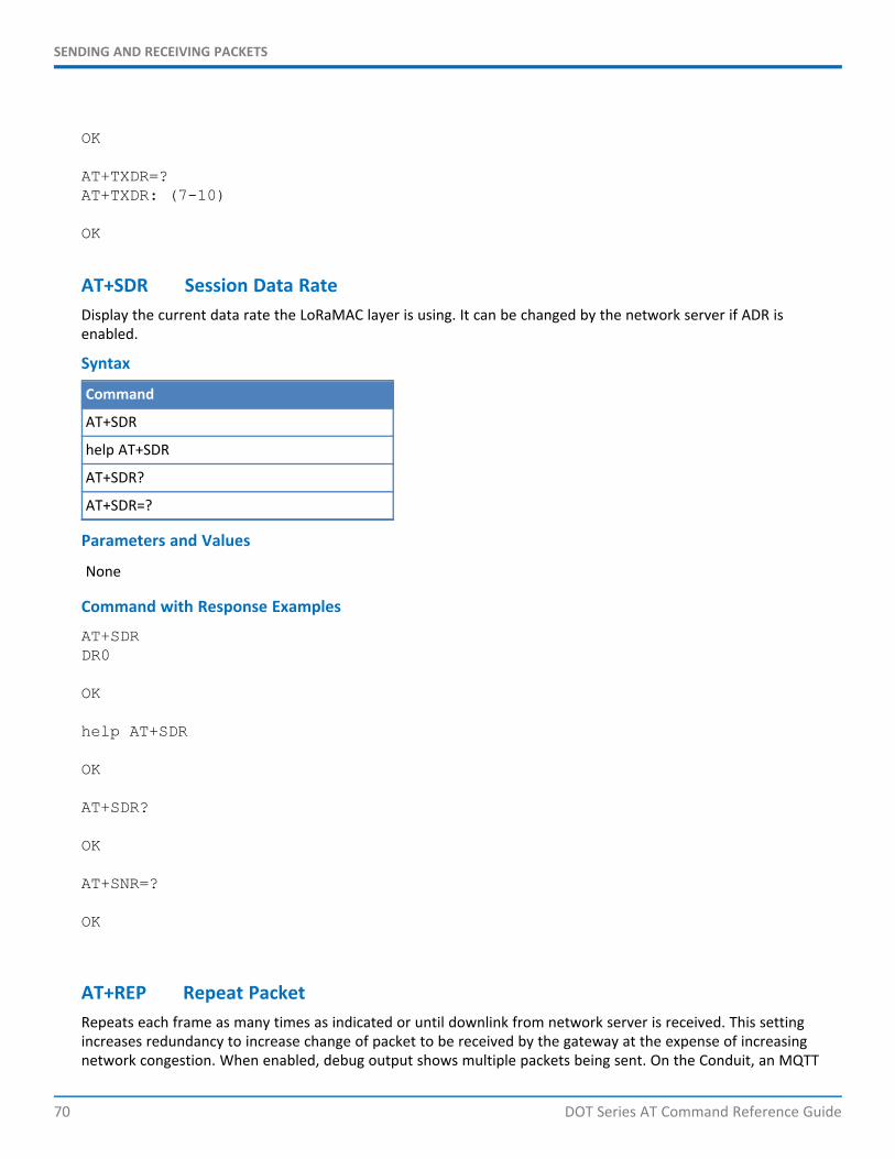
SENDING AND RECEIVING PACKETS
70 DOT Series AT Command Reference Guide
OK
AT+TXDR=?AT+TXDR: (7-10)
OK
AT+SDR Session Data RateDisplay the current data rate the LoRaMAC layer is using. It can be changed by the network server if ADR isenabled.
Syntax
Command
AT+SDR
help AT+SDR
AT+SDR?
AT+SDR=?
Parameters and Values
None
Command with Response Examples
AT+SDRDR0
OK
help AT+SDR
OK
AT+SDR?
OK
AT+SNR=?
OK
AT+REP Repeat PacketRepeats each frame as many times as indicated or until downlink from network server is received. This settingincreases redundancy to increase change of packet to be received by the gateway at the expense of increasingnetwork congestion. When enabled, debug output shows multiple packets being sent. On the Conduit, an MQTT
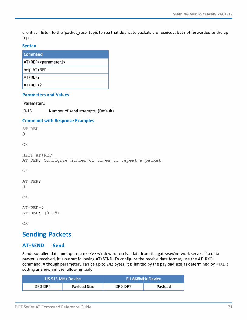
SENDING AND RECEIVING PACKETS
DOT Series AT Command Reference Guide 71
client can listen to the 'packet_recv' topic to see that duplicate packets are received, but not forwarded to the uptopic.
Syntax
Command
AT+REP=<parameter1>
help AT+REP
AT+REP?
AT+REP=?
Parameters and Values
Parameter1
0-15 Number of send attempts. (Default)
Command with Response Examples
AT+REP0
OK
HELP AT+REPAT+REP: Configure number of times to repeat a packet
OK
AT+REP?0
OK
AT+REP=?AT+REP: (0-15)
OK
Sending PacketsAT+SEND SendSends supplied data and opens a receive window to receive data from the gateway/network server. If a datapacket is received, it is output following AT+SEND. To configure the receive data format, use the AT+RXOcommand. Although parameter1 can be up to 242 bytes, it is limited by the payload size as determined by +TXDRsetting as shown in the following table:
US 915 MHz Device EU 868MHz Device
DR0-DR4 Payload Size DR0-DR7 Payload
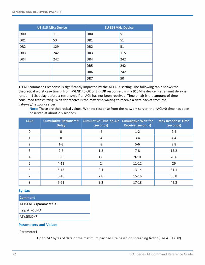
SENDING AND RECEIVING PACKETS
72 DOT Series AT Command Reference Guide
US 915 MHz Device EU 868MHz Device
DR0 11 DR0 51
DR1 53 DR1 51
DR2 129 DR2 51
DR3 242 DR3 115
DR4 242 DR4 242
DR5 242
DR6 242
DR7 50
+SEND commands response is significantly impacted by the AT+ACK setting. The following table shows thetheoretical worst case timing from +SEND to OK or ERROR response using a 915Mhz device. Retransmit delay israndom 1-3s delay before a retransmit if an ACK has not been received. Time on air is the amount of timeconsumed transmitting. Wait for receive is the max time waiting to receive a data packet from thegateway/network server.
Note: These are theoretical values. With no response from the network server, the +ACK=0 time has beenobserved at about 2.5 seconds.
+ACK Cumulative RetransmitDelay
Cumulative Time on Air(seconds)
Cumulative Wait forReceive (seconds)
Max Response Time(seconds)
0 0 .4 1-2 2.4
1 0 .4 3-4 4.4
2 1-3 .8 5-6 9.8
3 2-6 1.2 7-8 15.2
4 3-9 1.6 9-10 20.6
5 4-12 2 11-12 26
6 5-15 2.4 13-14 31.1
7 6-18 2.8 15-16 36.8
8 7-21 3.2 17-18 42.2
Syntax
Command
AT+SEND=<parameter1>
help AT+SEND
AT+SEND=?
Parameters and Values
Parameter1
Up to 242 bytes of data or the maximum payload size based on spreading factor (See AT+TXDR)
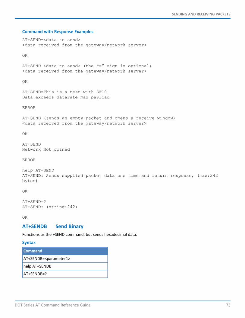
SENDING AND RECEIVING PACKETS
DOT Series AT Command Reference Guide 73
Command with Response Examples
AT+SEND=<data to send><data received from the gateway/network server>
OK
AT+SEND <data to send> (the “=” sign is optional)<data received from the gateway/network server>
OK
AT+SEND=This is a test with SF10Data exceeds datarate max payload
ERROR
AT+SEND (sends an empty packet and opens a receive window)<data received from the gateway/network server>
OK
AT+SENDNetwork Not Joined
ERROR
help AT+SENDAT+SEND: Sends supplied packet data one time and return response, (max:242bytes)
OK
AT+SEND=?AT+SEND: (string:242)
OK
AT+SENDB Send BinaryFunctions as the +SEND command, but sends hexadecimal data.
Syntax
Command
AT+SENDB=<parameter1>
help AT+SENDB
AT+SENDB=?
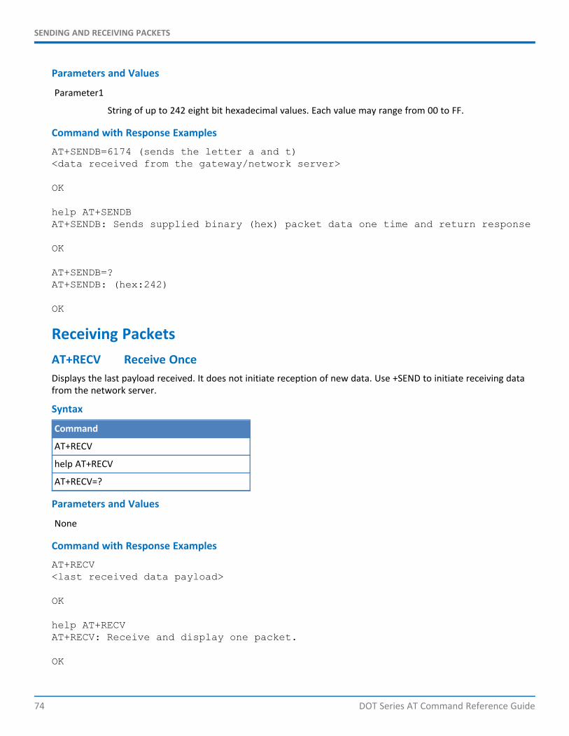
SENDING AND RECEIVING PACKETS
74 DOT Series AT Command Reference Guide
Parameters and Values
Parameter1
String of up to 242 eight bit hexadecimal values. Each value may range from 00 to FF.
Command with Response Examples
AT+SENDB=6174 (sends the letter a and t)<data received from the gateway/network server>
OK
help AT+SENDBAT+SENDB: Sends supplied binary (hex) packet data one time and return response
OK
AT+SENDB=?AT+SENDB: (hex:242)
OK
Receiving PacketsAT+RECV Receive OnceDisplays the last payload received. It does not initiate reception of new data. Use +SEND to initiate receiving datafrom the network server.
Syntax
Command
AT+RECV
help AT+RECV
AT+RECV=?
Parameters and Values
None
Command with Response Examples
AT+RECV<last received data payload>
OK
help AT+RECVAT+RECV: Receive and display one packet.
OK
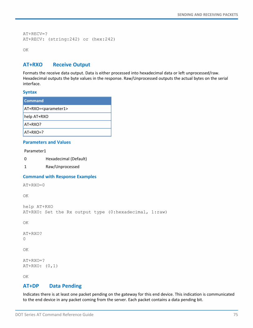
SENDING AND RECEIVING PACKETS
DOT Series AT Command Reference Guide 75
AT+RECV=?AT+RECV: (string:242) or (hex:242)
OK
AT+RXO Receive OutputFormats the receive data output. Data is either processed into hexadecimal data or left unprocessed/raw.Hexadecimal outputs the byte values in the response. Raw/Unprocessed outputs the actual bytes on the serialinterface.
Syntax
Command
AT+RXO=<parameter1>
help AT+RXO
AT+RXO?
AT+RXO=?
Parameters and Values
Parameter1
0 Hexadecimal (Default)
1 Raw/Unprocessed
Command with Response Examples
AT+RXO=0
OK
help AT+RXOAT+RXO: Set the Rx output type (0:hexadecimal, 1:raw)
OK
AT+RXO?0
OK
AT+RXO=?AT+RXO: (0,1)
OK
AT+DP Data PendingIndicates there is at least one packet pending on the gateway for this end device. This indication is communicatedto the end device in any packet coming from the server. Each packet contains a data pending bit.
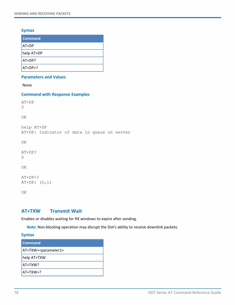
SENDING AND RECEIVING PACKETS
76 DOT Series AT Command Reference Guide
Syntax
Command
AT+DP
help AT+DP
AT+DP?
AT+DP=?
Parameters and Values
None
Command with Response Examples
AT+DP0
OK
help AT+DPAT+DP: Indicator of data in queue on server
OK
AT+DP?0
OK
AT+DP=?AT+DP: (0,1)
OK
AT+TXW Transmit WaitEnables or disables waiting for RX windows to expire after sending.
Note: Non-blocking operation may disrupt the Dot's ability to receive downlink packets.
Syntax
Command
AT+TXW=<parameter1>
help AT+TXW
AT+TXW?
AT+TXW=?
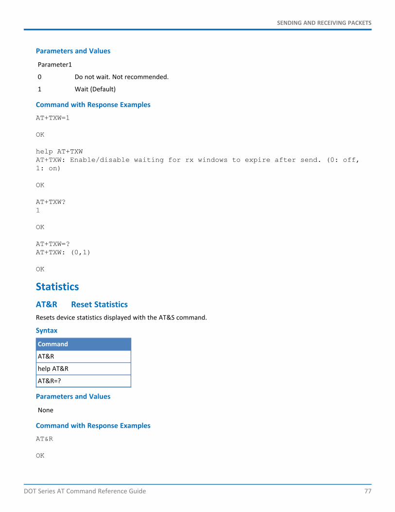
SENDING AND RECEIVING PACKETS
DOT Series AT Command Reference Guide 77
Parameters and Values
Parameter1
0 Do not wait. Not recommended.
1 Wait (Default)
Command with Response Examples
AT+TXW=1
OK
help AT+TXWAT+TXW: Enable/disable waiting for rx windows to expire after send. (0: off,1: on)
OK
AT+TXW?1
OK
AT+TXW=?AT+TXW: (0,1)
OK
StatisticsAT&R Reset StatisticsResets device statistics displayed with the AT&S command.
Syntax
Command
AT&R
help AT&R
AT&R=?
Parameters and Values
None
Command with Response Examples
AT&R
OK
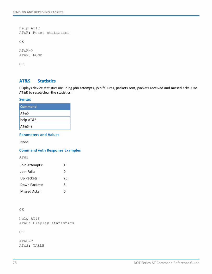
SENDING AND RECEIVING PACKETS
78 DOT Series AT Command Reference Guide
help AT&RAT&R: Reset statistics
OK
AT&R=?AT&R: NONE
OK
AT&S StatisticsDisplays device statistics including join attempts, join failures, packets sent, packets received and missed acks. UseAT&R to reset/clear the statistics.
Syntax
Command
AT&S
help AT&S
AT&S=?
Parameters and Values
None
Command with Response Examples
AT&S
Join Attempts: 1
Join Fails: 0
Up Packets: 25
Down Packets: 5
Missed Acks: 0
OK
help AT&SAT&S: Display statistics
OK
AT&S=?AT&S: TABLE
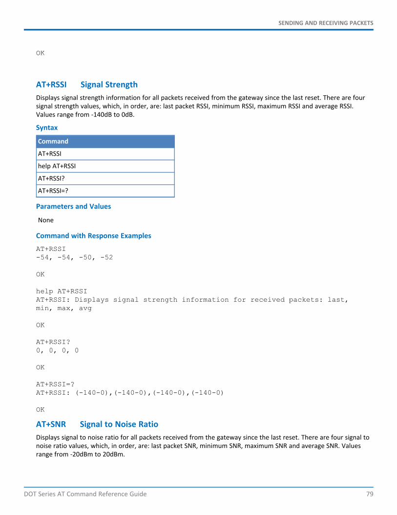
SENDING AND RECEIVING PACKETS
DOT Series AT Command Reference Guide 79
OK
AT+RSSI Signal StrengthDisplays signal strength information for all packets received from the gateway since the last reset. There are foursignal strength values, which, in order, are: last packet RSSI, minimum RSSI, maximum RSSI and average RSSI.Values range from -140dB to 0dB.
Syntax
Command
AT+RSSI
help AT+RSSI
AT+RSSI?
AT+RSSI=?
Parameters and Values
None
Command with Response Examples
AT+RSSI-54, -54, -50, -52
OK
help AT+RSSIAT+RSSI: Displays signal strength information for received packets: last,min, max, avg
OK
AT+RSSI?0, 0, 0, 0
OK
AT+RSSI=?AT+RSSI: (-140-0),(-140-0),(-140-0),(-140-0)
OK
AT+SNR Signal to Noise RatioDisplays signal to noise ratio for all packets received from the gateway since the last reset. There are four signal tonoise ratio values, which, in order, are: last packet SNR, minimum SNR, maximum SNR and average SNR. Valuesrange from -20dBm to 20dBm.
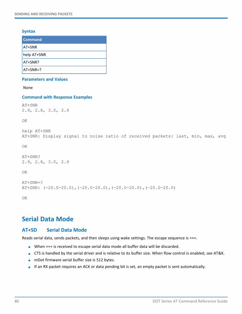
SENDING AND RECEIVING PACKETS
80 DOT Series AT Command Reference Guide
Syntax
Command
AT+SNR
help AT+SNR
AT+SNR?
AT+SNR=?
Parameters and Values
None
Command with Response Examples
AT+SNR2.9, 2.8, 3.0, 2.9
OK
help AT+SNRAT+SNR: Display signal to noise ratio of received packets: last, min, max, avg
OK
AT+SNR?2.9, 2.8, 3.0, 2.9
OK
AT+SNR=?AT+SNR: (-20.0-20.0),(-20.0-20.0),(-20.0-20.0),(-20.0-20.0)
OK
Serial Data ModeAT+SD Serial Data ModeReads serial data, sends packets, and then sleeps using wake settings. The escape sequence is +++.
When +++ is received to escape serial data mode all buffer data will be discarded.CTS is handled by the serial driver and is relative to its buffer size. When flow control is enabled, see AT&K.mDot firmware serial buffer size is 512 bytes.If an RX packet requires an ACK or data pending bit is set, an empty packet is sent automatically.

SENDING AND RECEIVING PACKETS
DOT Series AT Command Reference Guide 81
Syntax
Command
AT+SD
help AT+SD
AT+SD=?
Parameters and Values
None
Command with Response Examples
AT+SD
CONNECT<send data><send +++ to escape>OK
help AT+SDAT+SD: Enter serial data mode, exit with '+++'
OK
AT+SMODE Startup ModeConfigures which operation mode the end device powers up in, either AT command mode or serial data mode.
AT Command mode: The end device powers up or resets in command mode. AT commands are used tosend and receive data.Serial data mode: Allows the end device to send and receive data without entering AT commands. Datais sent and received based on wake command settings. This mode requires network join mode to be setfor either auto join or peer-to-peer mode. (AT+NJM=2 or 3).
Note: To exit serial data mode, reset the end device and input+++ within one second. If the end deviceresponds to AT commands, the +++ was successful. After exiting data mode issue AT+SMODE=0 to disabledata mode and AT&W to save the change.
Syntax
Command
AT+SMODE=<parameter1>
help AT+SMODE
AT+SMODE?
AT+SMODE=?
Parameters and Values
Parameter1
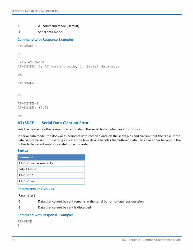
SENDING AND RECEIVING PACKETS
82 DOT Series AT Command Reference Guide
0 AT command mode (Default)
1 Serial data mode
Command with Response Examples
AT+SMODE=0
OK
help AT+SMODEAT+SMODE: 0: AT command mode, 1: Serial data mode
OK
AT+SMODE?0
OK
AT+SMODE=?AT+SMODE: (0,1)
OK
AT+SDCE Serial Data Clear on ErrorSets the device to either keep or discard data in the serial buffer when an error occurs.
In serial data mode, the dot wakes periodically to received data on the serial pins and transmit out the radio. If thedata cannot be sent, this setting indicates the how device handles the buffered data. Data can either be kept in thebuffer to be resent until successful or be discarded.
Syntax
Command
AT+SDCE=<parameter1>
help AT+SDCE
AT+SDCE?
AT+SDCE=?
Parameters and Values
Parameter1
0 Data that cannot be sent remains in the serial buffer for later transmission
1 Data that cannot be sent is discarded
Command with Response Examples
AT+SDCE1
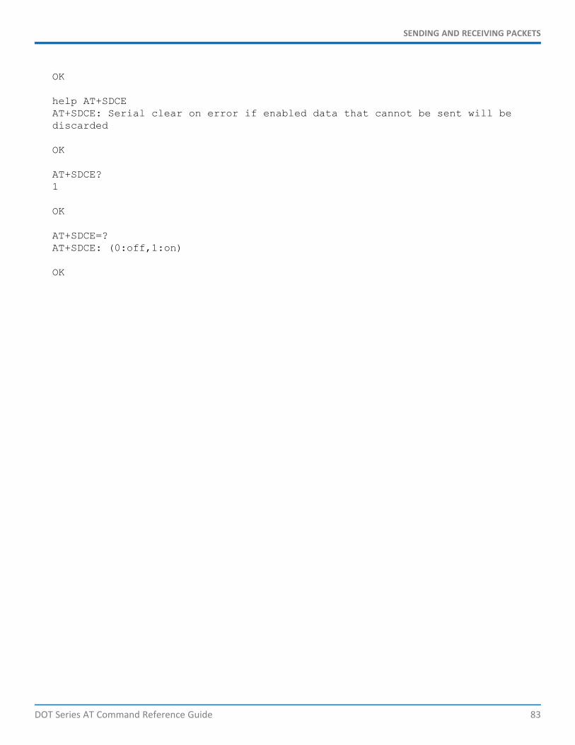
SENDING AND RECEIVING PACKETS
DOT Series AT Command Reference Guide 83
OK
help AT+SDCEAT+SDCE: Serial clear on error if enabled data that cannot be sent will bediscarded
OK
AT+SDCE?1
OK
AT+SDCE=?AT+SDCE: (0:off,1:on)
OK

POWER MANAGEMENT
84 DOT Series AT Command Reference Guide
Chapter 5 – Power ManagementAT+SLEEP Sleep ModePuts the end device in sleep mode. The end device wakes on interrupt or interval based on AT+WM setting. Onceawakened, use AT+SLEEP again to return to sleep mode.
Note: Deep sleep is not available for mDot devices.
Deep Sleep (ST Micro standby mode) is the lowest power mode. All RAM is lost and peripherals are off. You canuse backup registers to retain the state over sleep. The dot library keeps the running state in the backup registersto be reloaded automatically to maintain the session. Execution begins at the start of the program as it would frompower up.
Sleep (ST Micro stop mode) maintains RAM and keeps peripherals on. Execution resumes from the call to sleep.
If you need to wake the device at a specific 1 msec timing, take the following values into account.Waking from Deep Sleep takes 314-407 usecWaking from Sleep takes 13-14 usecRTC period is 30.5 usec
SyntaxCommand
AT+SLEEP=<parameter1>
help AT+SLEEP
AT+SLEEP=?
Parameters and ValuesParameter1
0 Deep sleep (ST Micro standby mode)
1 Sleep (ST Micro stop mode )
Command with Response ExamplesAT+SLEEP
AT+SLEEP=0
AT+SLEEP=1
help AT+SLEEPAT+SLEEP: Enter sleep mode
OK
AT+SLEEP=?AT+SLEEP: NONE
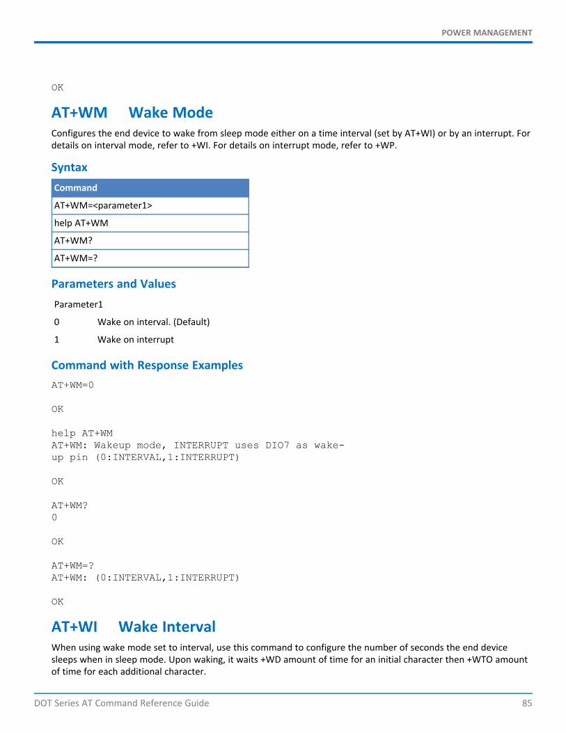
POWER MANAGEMENT
DOT Series AT Command Reference Guide 85
OK
AT+WM Wake ModeConfigures the end device to wake from sleep mode either on a time interval (set by AT+WI) or by an interrupt. Fordetails on interval mode, refer to +WI. For details on interrupt mode, refer to +WP.
SyntaxCommand
AT+WM=<parameter1>
help AT+WM
AT+WM?
AT+WM=?
Parameters and ValuesParameter1
0 Wake on interval. (Default)
1 Wake on interrupt
Command with Response ExamplesAT+WM=0
OK
help AT+WMAT+WM: Wakeup mode, INTERRUPT uses DIO7 as wake-up pin (0:INTERVAL,1:INTERRUPT)
OK
AT+WM?0
OK
AT+WM=?AT+WM: (0:INTERVAL,1:INTERRUPT)
OK
AT+WI Wake IntervalWhen using wake mode set to interval, use this command to configure the number of seconds the end devicesleeps when in sleep mode. Upon waking, it waits +WD amount of time for an initial character then +WTO amountof time for each additional character.
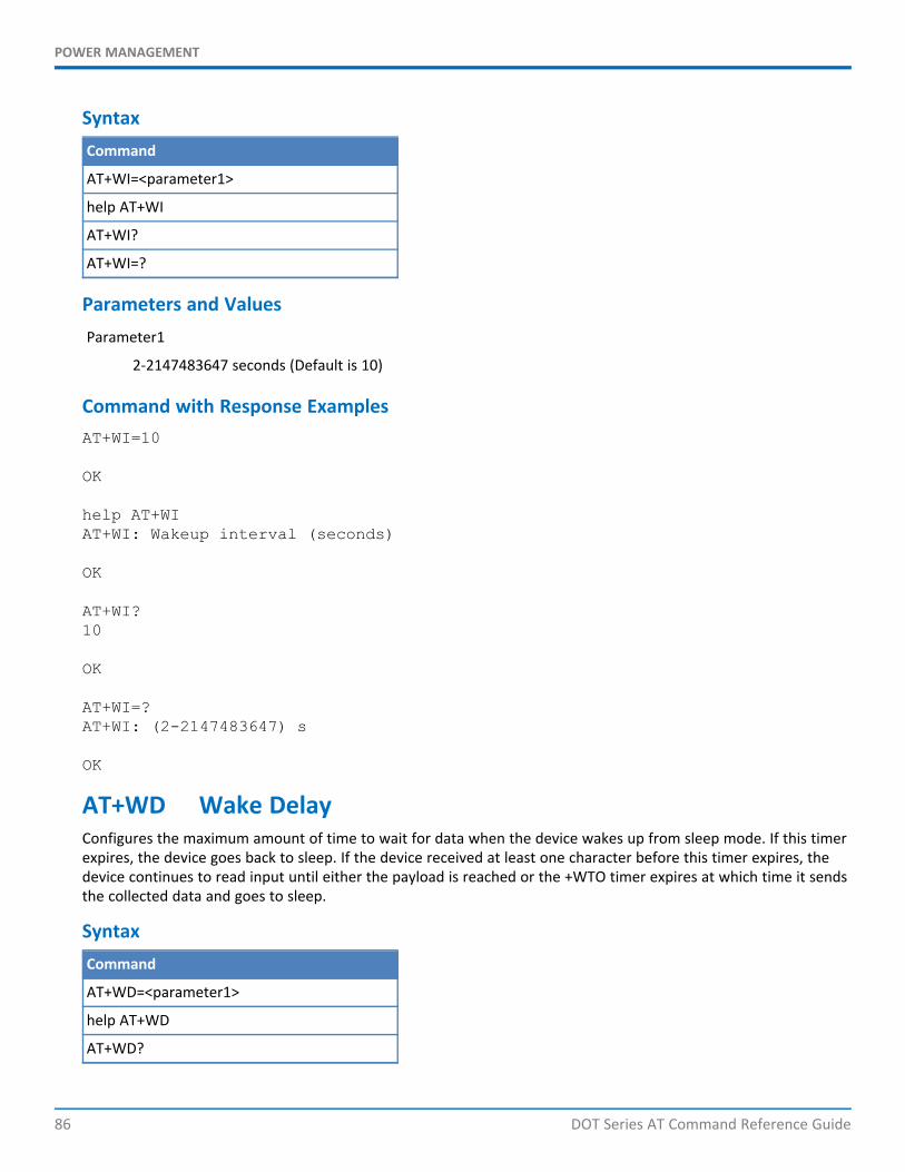
POWER MANAGEMENT
86 DOT Series AT Command Reference Guide
SyntaxCommand
AT+WI=<parameter1>
help AT+WI
AT+WI?
AT+WI=?
Parameters and ValuesParameter1
2-2147483647 seconds (Default is 10)
Command with Response ExamplesAT+WI=10
OK
help AT+WIAT+WI: Wakeup interval (seconds)
OK
AT+WI?10
OK
AT+WI=?AT+WI: (2-2147483647) s
OK
AT+WD Wake DelayConfigures the maximum amount of time to wait for data when the device wakes up from sleep mode. If this timerexpires, the device goes back to sleep. If the device received at least one character before this timer expires, thedevice continues to read input until either the payload is reached or the +WTO timer expires at which time it sendsthe collected data and goes to sleep.
SyntaxCommand
AT+WD=<parameter1>
help AT+WD
AT+WD?
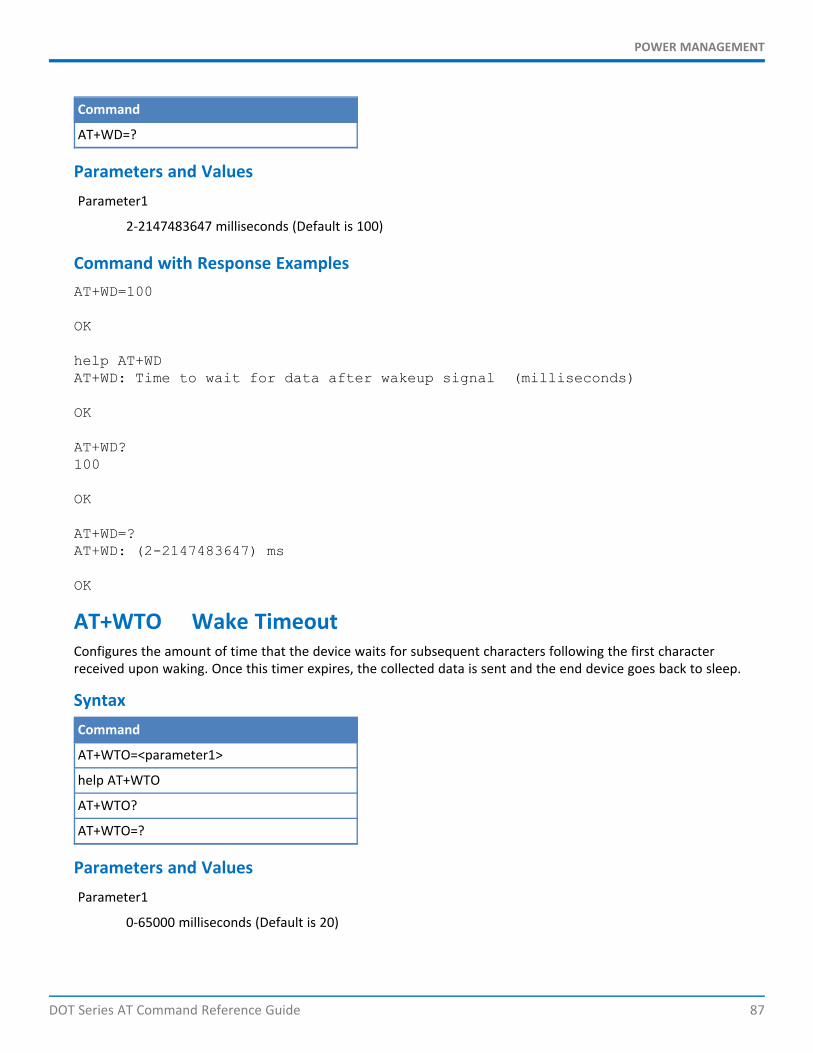
POWER MANAGEMENT
DOT Series AT Command Reference Guide 87
Command
AT+WD=?
Parameters and ValuesParameter1
2-2147483647 milliseconds (Default is 100)
Command with Response ExamplesAT+WD=100
OK
help AT+WDAT+WD: Time to wait for data after wakeup signal (milliseconds)
OK
AT+WD?100
OK
AT+WD=?AT+WD: (2-2147483647) ms
OK
AT+WTO Wake TimeoutConfigures the amount of time that the device waits for subsequent characters following the first characterreceived upon waking. Once this timer expires, the collected data is sent and the end device goes back to sleep.
SyntaxCommand
AT+WTO=<parameter1>
help AT+WTO
AT+WTO?
AT+WTO=?
Parameters and ValuesParameter1
0-65000 milliseconds (Default is 20)

POWER MANAGEMENT
88 DOT Series AT Command Reference Guide
Command with Response ExamplesAT+WTO=20
OK
help AT+WTOAT+WTO: Read serial data until timeout (milliseconds)
OK
AT+WTO?20
OK
AT+WTO=?AT+WTO: (0-65000) ms
OK
AT+ANT Antenna GainAllows a non-default antenna to be used while still adhering to transmit power regulations.
SyntaxCommand
AT+ANT=<parameter1>
help AT+ANT
AT+ANT?
AT+ANT=?
Parameters and ValuesParameter1
-128 to 127 (Default is 3)
Command with Response ExamplesAT+ANT=3
OK
help AT+ANTAT+ANT: Gain in dBi of installed antenna (-128-127)
OK
POWER MANAGEMENT
DOT Series AT Command Reference Guide 89
AT+ANT?3
OK
AT+ANT=?AT+ANT: (-128-127)
OK
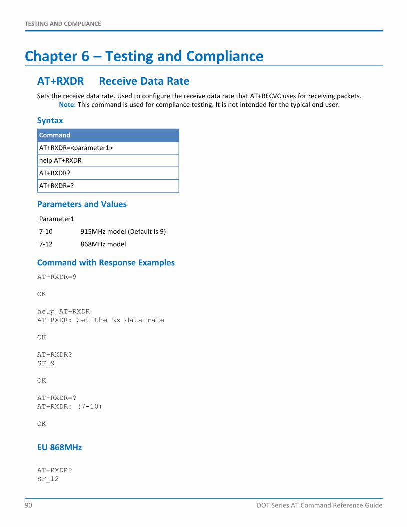
TESTING AND COMPLIANCE
90 DOT Series AT Command Reference Guide
Chapter 6 – Testing and ComplianceAT+RXDR Receive Data RateSets the receive data rate. Used to configure the receive data rate that AT+RECVC uses for receiving packets.
Note: This command is used for compliance testing. It is not intended for the typical end user.
SyntaxCommand
AT+RXDR=<parameter1>
help AT+RXDR
AT+RXDR?
AT+RXDR=?
Parameters and ValuesParameter1
7-10 915MHz model (Default is 9)
7-12 868MHz model
Command with Response ExamplesAT+RXDR=9
OK
help AT+RXDRAT+RXDR: Set the Rx data rate
OK
AT+RXDR?SF_9
OK
AT+RXDR=?AT+RXDR: (7-10)
OK
EU 868MHz
AT+RXDR?SF_12
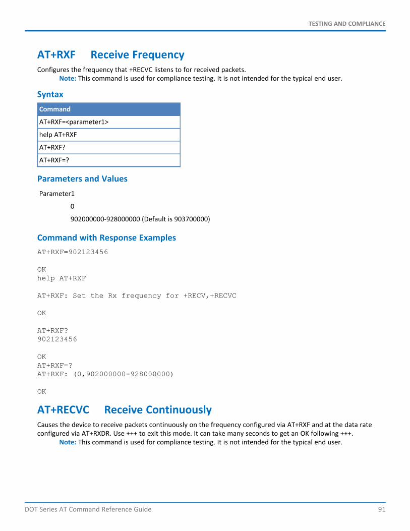
TESTING AND COMPLIANCE
DOT Series AT Command Reference Guide 91
AT+RXF Receive FrequencyConfigures the frequency that +RECVC listens to for received packets.
Note: This command is used for compliance testing. It is not intended for the typical end user.
SyntaxCommand
AT+RXF=<parameter1>
help AT+RXF
AT+RXF?
AT+RXF=?
Parameters and ValuesParameter1
0
902000000-928000000 (Default is 903700000)
Command with Response ExamplesAT+RXF=902123456
OKhelp AT+RXF
AT+RXF: Set the Rx frequency for +RECV,+RECVC
OK
AT+RXF?902123456
OKAT+RXF=?AT+RXF: (0,902000000-928000000)
OK
AT+RECVC Receive ContinuouslyCauses the device to receive packets continuously on the frequency configured via AT+RXF and at the data rateconfigured via AT+RXDR. Use +++ to exit this mode. It can take many seconds to get an OK following +++.
Note: This command is used for compliance testing. It is not intended for the typical end user.
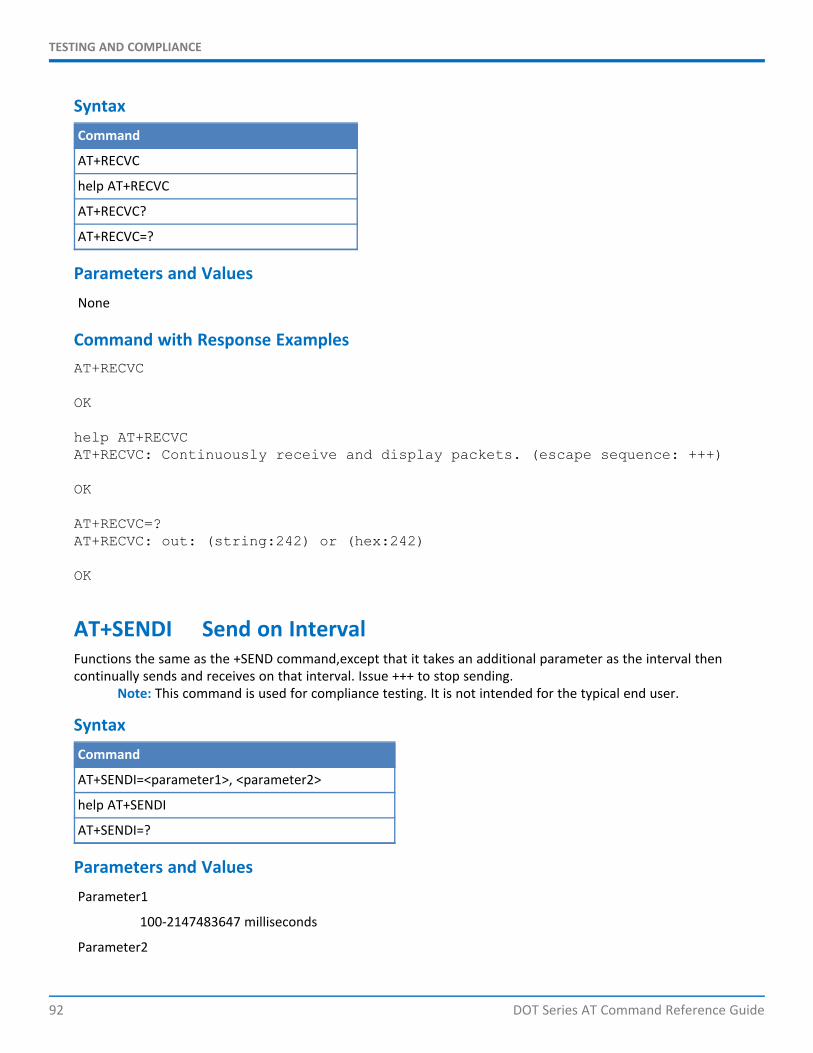
TESTING AND COMPLIANCE
92 DOT Series AT Command Reference Guide
SyntaxCommand
AT+RECVC
help AT+RECVC
AT+RECVC?
AT+RECVC=?
Parameters and ValuesNone
Command with Response ExamplesAT+RECVC
OK
help AT+RECVCAT+RECVC: Continuously receive and display packets. (escape sequence: +++)
OK
AT+RECVC=?AT+RECVC: out: (string:242) or (hex:242)
OK
AT+SENDI Send on IntervalFunctions the same as the +SEND command,except that it takes an additional parameter as the interval thencontinually sends and receives on that interval. Issue +++ to stop sending.
Note: This command is used for compliance testing. It is not intended for the typical end user.
SyntaxCommand
AT+SENDI=<parameter1>, <parameter2>
help AT+SENDI
AT+SENDI=?
Parameters and ValuesParameter1
100-2147483647 milliseconds
Parameter2
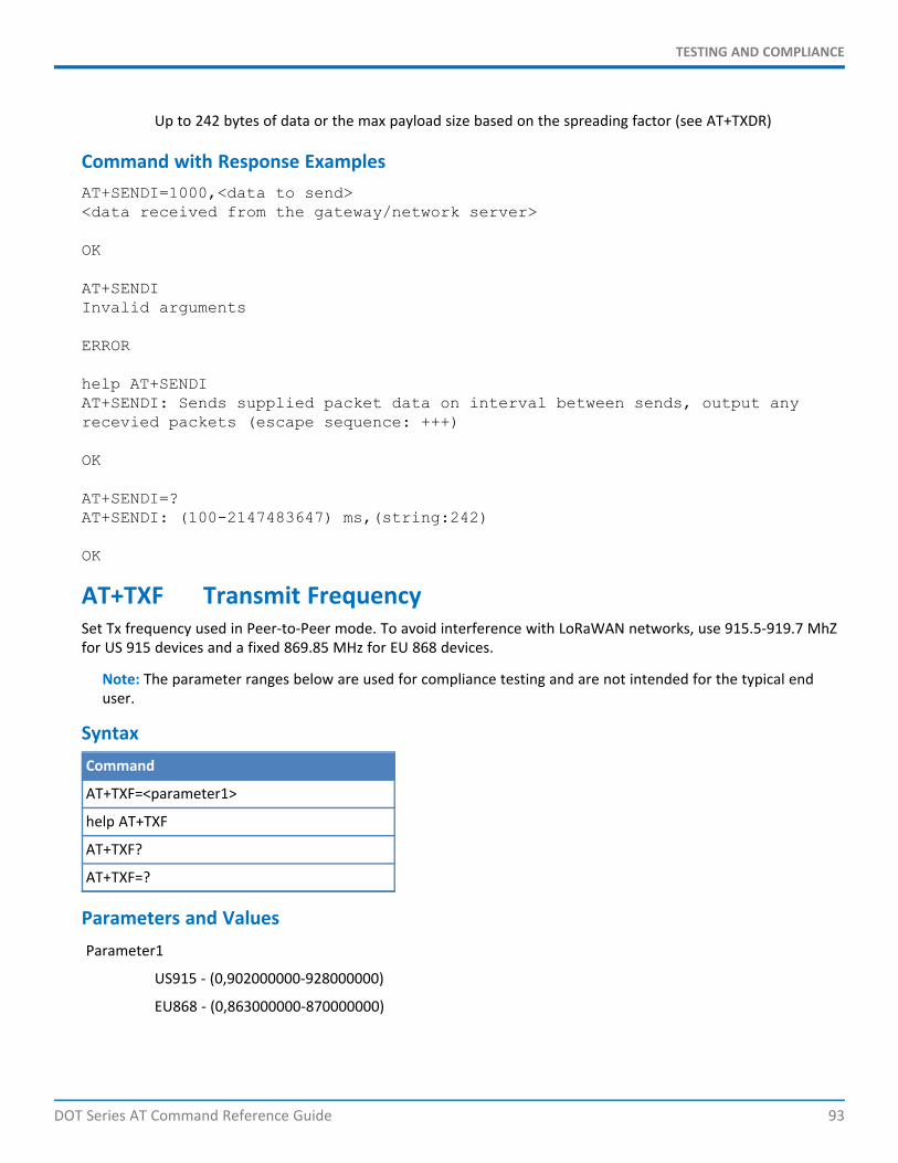
TESTING AND COMPLIANCE
DOT Series AT Command Reference Guide 93
Up to 242 bytes of data or the max payload size based on the spreading factor (see AT+TXDR)
Command with Response ExamplesAT+SENDI=1000,<data to send><data received from the gateway/network server>
OK
AT+SENDIInvalid arguments
ERROR
help AT+SENDIAT+SENDI: Sends supplied packet data on interval between sends, output anyrecevied packets (escape sequence: +++)
OK
AT+SENDI=?AT+SENDI: (100-2147483647) ms,(string:242)
OK
AT+TXF Transmit FrequencySet Tx frequency used in Peer-to-Peer mode. To avoid interference with LoRaWAN networks, use 915.5-919.7 MhZfor US 915 devices and a fixed 869.85 MHz for EU 868 devices.
Note: The parameter ranges below are used for compliance testing and are not intended for the typical enduser.
SyntaxCommand
AT+TXF=<parameter1>
help AT+TXF
AT+TXF?
AT+TXF=?
Parameters and ValuesParameter1
US915 - (0,902000000-928000000)
EU868 - (0,863000000-870000000)
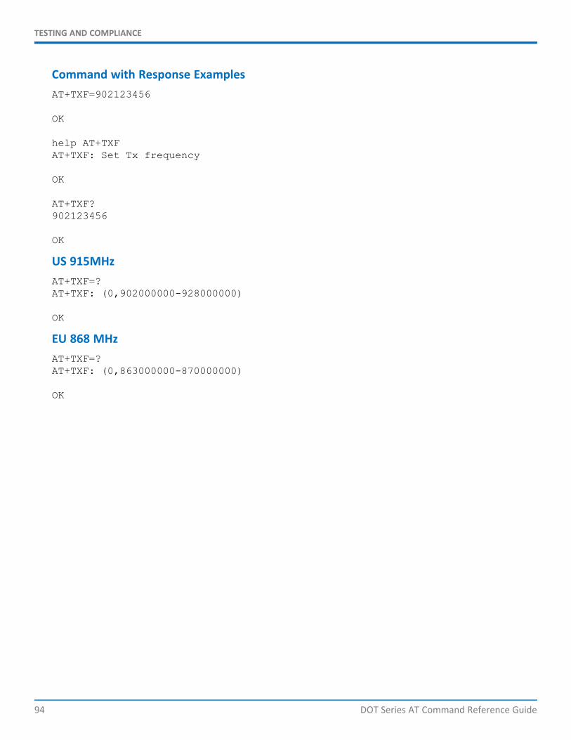
TESTING AND COMPLIANCE
94 DOT Series AT Command Reference Guide
Command with Response ExamplesAT+TXF=902123456
OK
help AT+TXFAT+TXF: Set Tx frequency
OK
AT+TXF?902123456
OK
US 915MHzAT+TXF=?AT+TXF: (0,902000000-928000000)
OK
EU 868 MHzAT+TXF=?AT+TXF: (0,863000000-870000000)
OK
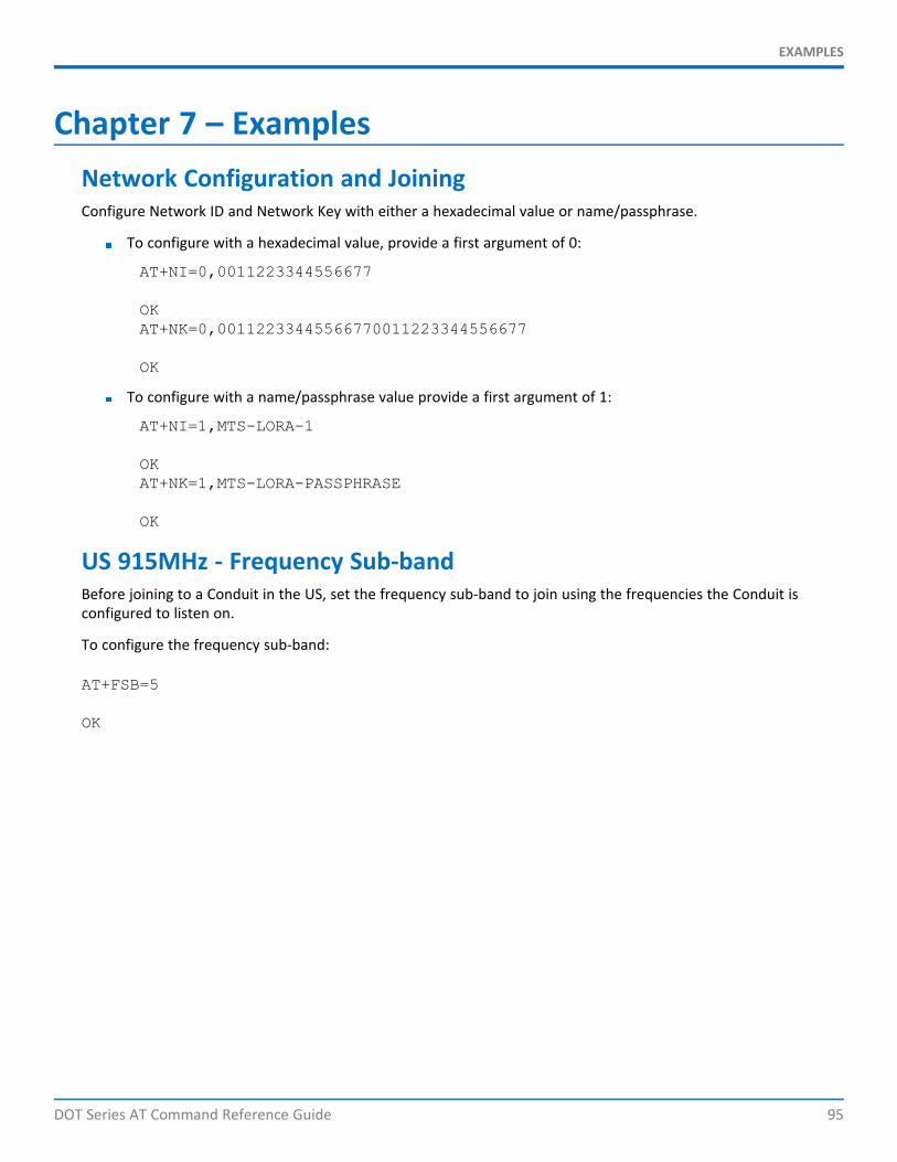
EXAMPLES
DOT Series AT Command Reference Guide 95
Chapter 7 – ExamplesNetwork Configuration and JoiningConfigure Network ID and Network Key with either a hexadecimal value or name/passphrase.
To configure with a hexadecimal value, provide a first argument of 0:
AT+NI=0,0011223344556677
OKAT+NK=0,00112233445566770011223344556677
OK
To configure with a name/passphrase value provide a first argument of 1:
AT+NI=1,MTS-LORA-1
OKAT+NK=1,MTS-LORA-PASSPHRASE
OK
US 915MHz - Frequency Sub-bandBefore joining to a Conduit in the US, set the frequency sub-band to join using the frequencies the Conduit isconfigured to listen on.
To configure the frequency sub-band:
AT+FSB=5
OK

EXAMPLES
96 DOT Series AT Command Reference Guide
Join ModeThe Dot supports both OTA and manual provisioning or joining. See OTA Activation in Chapter 3 NetworkManagement.
To configure for OTA join mode and connect to the network:
AT+NJM=1
OKAT+JOIN
OK
To configure for AUTO OTA join mode and connect to the network, if you are not already joined, a joinattempt will be made:
AT+NJM=2
OK
Joining Network... Network Joined
OK
To configure for MANUAL provisioning, change the mode, then set the network address and session keys:
AT+NJM=0
OK
AT+NA=0011223344556677
OK
AT+DSK=00112233445566770011223344556677
OK
AT+NSK=00112233445566770011223344556677
OK

EXAMPLES
DOT Series AT Command Reference Guide 97
Ensuring Network ConnectivityTo ensure the Dot is still connected to the network, request a response from the server. One method is to requireACKs for each packet, but under a heavy load, the server may not be able to respond to every packet. The otheroption is to periodically require an ACK using AT+LCC, this maintains join status without overburdening thenetwork server. In the following examples, the gateway is powered off to simulate network loss. Refer to EnsuringNetwork Connectivity in Chapter 3 Network Management.
Using acknowledgments to detect network loss requires a response for each packet. With a threshold set toone, the network is no longer joined after only one lost packet. Increasing the LCT value allows some missedpackets without the need to rejoin the network. If AUTO_OTA is enabled the device automatically attemptsto rejoin after network is lost.
[Gateway Powered On]AT+JOINSuccessfully joined network
OKAT+ACK=1
OKAT+LCT=1
OKAT+SEND=message
OK[Gateway Powered Off]
AT+NJS1
OKAT+SEND=messageOperation Timed Out - ACK not received
OKAT+NJS0
OK
When using link checks to detect network loss, you can configure how many responses are required. With athreshold set to one, the network is no longer joined after only one lost packet. Increasing the LCT valueallows some missed packets without the need to rejoin the network. If AUTO_OTA is enabled the deviceautomatically attempts to rejoin after network is lost.
[Gateway Powered On]
AT+JOINSuccessfully joined network
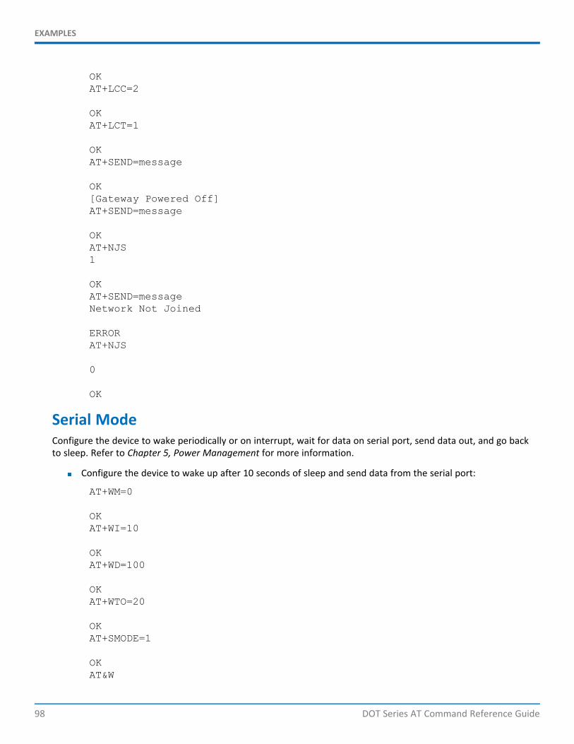
EXAMPLES
98 DOT Series AT Command Reference Guide
OKAT+LCC=2
OKAT+LCT=1
OKAT+SEND=message
OK[Gateway Powered Off]AT+SEND=message
OKAT+NJS1
OKAT+SEND=messageNetwork Not Joined
ERRORAT+NJS
0
OK
Serial ModeConfigure the device to wake periodically or on interrupt, wait for data on serial port, send data out, and go backto sleep. Refer to Chapter 5, Power Management for more information.
Configure the device to wake up after 10 seconds of sleep and send data from the serial port:
AT+WM=0
OKAT+WI=10
OKAT+WD=100
OKAT+WTO=20
OKAT+SMODE=1
OKAT&W
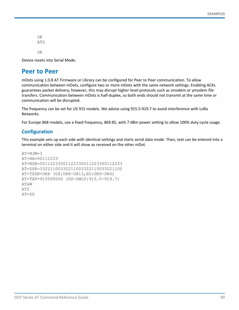
EXAMPLES
DOT Series AT Command Reference Guide 99
OKATZ
OK
Device resets into Serial Mode.
Peer to PeermDots using 1.0.8 AT Firmware or Library can be configured for Peer to Peer communication. To allowcommunication between mDots, configure two or more mDots with the same network settings. Enabling ACKsguarantees packet delivery; however, this may disrupt higher level protocols such as zmodem or ymodem filetransfers. Communication between mDots is half-duplex, so both ends should not transmit at the same time orcommunication will be disrupted.
The frequency can be set for US 915 models. We advise using 915.5-919.7 to avoid interference with LoRaNetworks.
For Europe 868 models, use a fixed frequency, 869.85, with 7 dBm power setting to allow 100% duty-cycle usage.
ConfigurationThis example sets up each side with identical settings and starts serial data mode. Then, text can be entered into aterminal on either side and it will show as received on the other mDot.
AT+NJM=3AT+NA=00112233AT+NSK=00112233001122330011223300112233AT+DSK=33221100332211003322110033221100AT+TXDR=DR8 (US:DR8-DR13,EU:DR0-DR6)AT+TXF=915500000 (US-ONLY:915.5-919.7)AT&WATZAT+SD

EXAMPLES
100 DOT Series AT Command Reference Guide
Peer-to-Peer Throughput