dot/faa/ar-01/39 in-pavement light emitting diode (led ... · in-pavement light emitting diode...
TRANSCRIPT

DOT/FAA/AR-01/39 Office of Aviation Research Washington, D.C. 20591
In-Pavement Light Emitting Diode (LED) Light Strip Evaluation Donald W. Gallagher Federal Aviation Administration William J. Hughes Technical Center Airport and Aircraft Safety Research and Development Division Atlantic City International Airport, NJ 08405 August 2001 Interim Report This document is available to the U.S. public through the National Technical Information Service (NTIS), Springfield, Virginia 22161.
U.S. Department of Transportation Federal Aviation Administration

NOTICE
This document is disseminated under the sponsorship of the U.S. Department of Transportation in the interest of information exchange. The United States Government assumes no liability for the contents or use thereof. The United States Government does not endorse products or manufacturers. Trade or manufacturer's names appear herein solely because they are considered essential to the objective of this report. This document does not constitute FAA certification policy. Consult your local FAA airports office as to its use. This report is available at the Federal Aviation Administration William J. Hughes Technical Center's Full-Text Technical Reports page: actlibrary.tc.faa.gov in Adobe Acrobat portable document format (PDF).
Technical Report Documentation Page 1. Report No. DOT/FAA/AR-01/39
2. Government Accession No. 3. Recipient's Catalog No.
4. Title and Subtitle
IN-PAVEMENT LIGHT EMITTING DIODE (LED) LIGHT STRIP 5. Report Date
August 2001 EVALUATION 6. Performing Organization Code
AAR-410
7. Author(s)
Donald W. Gallagher 8. Performing Organization Report No.
9. Performing Organization Name and Address
Federal Aviation Administration William J. Hughes Technical Center Airport and Aircraft Safety
10. Work Unit No. (TRAIS)
Research and Development Division Airport Safety Technology Section Atlantic City International Airport, NJ 08405
11. Contract or Grant No.
12. Sponsoring Agency Name and Address
U.S. Department of Transportation Federal Aviation Administration
13. Type of Report and Period Covered
Interim Report
Office of Aviation Research Washington, DC 20591
14. Sponsoring Agency Code
AAS-200 15. Supplementary Notes
16. Abstract
Painted markings on runways, taxiways, and apron surfaces are often obliterated, particularly at night, when covered by even a thin layer of water or other forms of precipitation. An effective method for delineating critical areas and/or locations on the airport surface is essential. Recently developed usage of light emitting diode (LED) light sources have been the encapsulation of a �string� of LED lights to provide a continuous light strip. These strips can be readily imbedded within, and virtually flush with, the pavement surface. Properly installed, they should be completely compatible with snowplow operations and, being sealed or encapsulated, would require only a minimum of maintenance. LED devices require comparatively low levels of power and have demonstrated minimal failure rates in service. A test LED-strip configuration was installed in the form of a parking location �T� at the number one parking spot on the apron area of the Federal Aviation Administration William J. Hughes Technical Center. It was comprised of five 3-meter (10-foot) sections, or strips, forming the crossbar of the T and an additional nine sections forming the �tail� of the T. Experienced pilots and lighting personnel participated in a subjective evaluation consisting of a series of questions to evaluate the parking location configuration. All participants felt that they could see and identify the LED-strip lighting in time to easily execute the approach to the parking spot. All participants felt the LED lighting presentation was sufficiently clear and it identified the location for what it was, a parking position. All but one of the participants rated this proposed addition/modification to painted surface markings as �well worth while,� one rated it �marginal help.� In conclusion, operationally, the LED light strips do enhance airport paint markings. This technology can be acquired from a much farther distance than paint markings. Another major advantage of this technology is its visibility when covered with standing water, whereas paint markings become obliterated. On the issue of snow covering, however, this technology becomes obliterated the same as paint markings. 17. Key Words
LED, Light emitting diodes, Pavement marking enhancement, lighting
18. Distribution Statement
This document is available to the public through the National Technical Information Service (NTIS) Springfield, Virginia 22161.
19. Security Classif. (of this report)
Unclassified
20. Security Classif. (of this page)
Unclassified
21. No. of Pages
16 22. Price
Form DOT F1700.7 (8-72) Reproduction of completed page authorized
TABLE OF CONTENTS
Page EXECUTIVE SUMMARY v INTRODUCTION 1 Purpose 1 Background 1 Related Activities/Documents 1 DISCUSSION 2 INSTALLATION 2 EVALUATION 4 Procedure 4 Subject Evaluators 6 TEST RESULTS 6 Parking Location Indicator (Permanent Installation) 6 General Considerations 8 Maintenance 10 RECOMMENDATIONS 11 CONCLUSIONS 11
LIST OF FIGURES Figure Page 1 Vancouver, British Columbia Airport Demonstration Installation 2 2 Parking Location Indicator Layout 3 3 LED-Strip Section Photograph 4 4 Subject Evaluator Sample Questionnaire 5 5 Questionnaire Summary 7 6 Taxi Route and Display Locations 8 7 Postsnow Appearance 9 8 Connection Space Between LED Sections 10
iii/iv

EXECUTIVE SUMMARY
The purpose of this evaluation was to investigate the potential for using light emitting diode (LED) light sources to enhance painted markings on nonmovement areas at airports and, thus, more effectively delineate critical areas and/or locations. While the principal purpose of this report is to describe the effectiveness of LED strips in delineating ramp or apron parking locations, some discussion of installation techniques and considerations are included. It should be noted that the LED-strip system components provided by the manufacturer were �first generation� prototypes and, therefore, not designed with the benefit of previous experience with the airport environment. The results of the questions asked from experienced pilots and lighting personnel on the parking location installation were • All participants felt that they could see and identify the LED-strip lighting in time to
easily execute the approach to the parking spot. • All participants felt the LED-lighting presentation was sufficiently clear, and that it
identified the location for what it was, a parking position. • Eighty-nine percent of the participants rated this proposed addition/modification to the
painted surface markings as �well worth while,� 11% rated it �marginal help.� It was concluded that, operationally, this technology does enhance paint markings. There are four issues that need further research. 1. Development of performance standards for this nonpoint source technology is needed in
order to publish appropriate advisory circulars and or specifications. 2. Installation procedures need to be refined and standardized. 3. Equipment to be procured for future evaluation must be redesigned to better suit the
hostile airport environment. This pertains particularly to the method of connecting the LED strips to the feeder power cables.
4. Use of LED-strip lights to enhance movement area markings, such as at runway/taxiway
and taxiway/taxiway intersection holding positions, needs to be investigated further.
v/vi

INTRODUCTION
PURPOSE.
The purpose of this evaluation was to investigate the potential for using light emitting diode (LED) light sources to enhance painted markings on airports and, thus, more effectively delineate critical areas and/or locations. Since only a LED-strip parking locator configuration, intended for airport apron use, was installed permanently for formal evaluation, this report is an interim document. The work is being performed in response to a request from the Office of Airport Standards, AAS-200, project number 98-401. BACKGROUND.
Since painted markings on runways, taxiways, and apron surfaces are often obliterated at night when covered by even a thin layer of water or other form of precipitation, there is a need to provide a more effective method for indicating critical areas to airport users. Conventional in-pavement (semiflush/inset) lights can be used, but they are expensive and costly to install and maintain. Recently developed and most promising usage of LED light sources has been the encapsulation of a �string� of LED lights to provide a continuous light strip. These strips, approximately 3 meters (10 feet) in length, can then be readily imbedded within, and virtually flush with, the pavement surface. If properly installed, the strips should be completely compatible with snowplow operations and, being sealed or encapsulated, would require only a minimum of maintenance. LED devices are noted for requiring comparatively low levels of power and have demonstrated minimal failure rates in service. RELATED ACTIVITIES/DOCUMENTS.
A prototype LED light strip system has been tested in a movement area, in the form of a yellow parking boundary line at a taxiway run-up area, by the Port Authority of New York and New Jersey (PONYNJ) at the J. F. Kennedy International Airport in New York City. The installation, serving to demonstrate installation techniques, has been inspected by various airport engineering and operations groups. In addition, a somewhat more complex configuration in the form of a numbered gate indicator with centerline track was installed for demonstration on the Vancouver, British Columbia (BC) Airport apron. A photograph taken under standing water conditions is shown in figure 1. No documentation concerning either of these demonstrations has been made available for inclusion in the report.
1
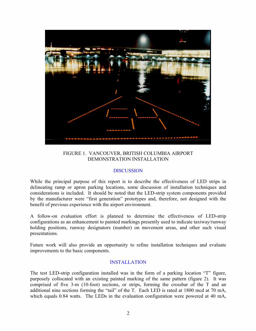
FIGURE 1. VANCOUVER, BRITISH COLUMBIA AIRPORT DEMONSTRATION INSTALLATION
DISCUSSION
While the principal purpose of this report is to describe the effectiveness of LED strips in delineating ramp or apron parking locations, some discussion of installation techniques and considerations is included. It should be noted that the LED-strip system components provided by the manufacturer were �first generation� prototypes and, therefore, not designed with the benefit of previous experience with the airport environment. A follow-on evaluation effort is planned to determine the effectiveness of LED-strip configurations as an enhancement to painted markings presently used to indicate taxiway/runway holding positions, runway designators (number) on movement areas, and other such visual presentations. Future work will also provide an opportunity to refine installation techniques and evaluate improvements to the basic components.
INSTALLATION
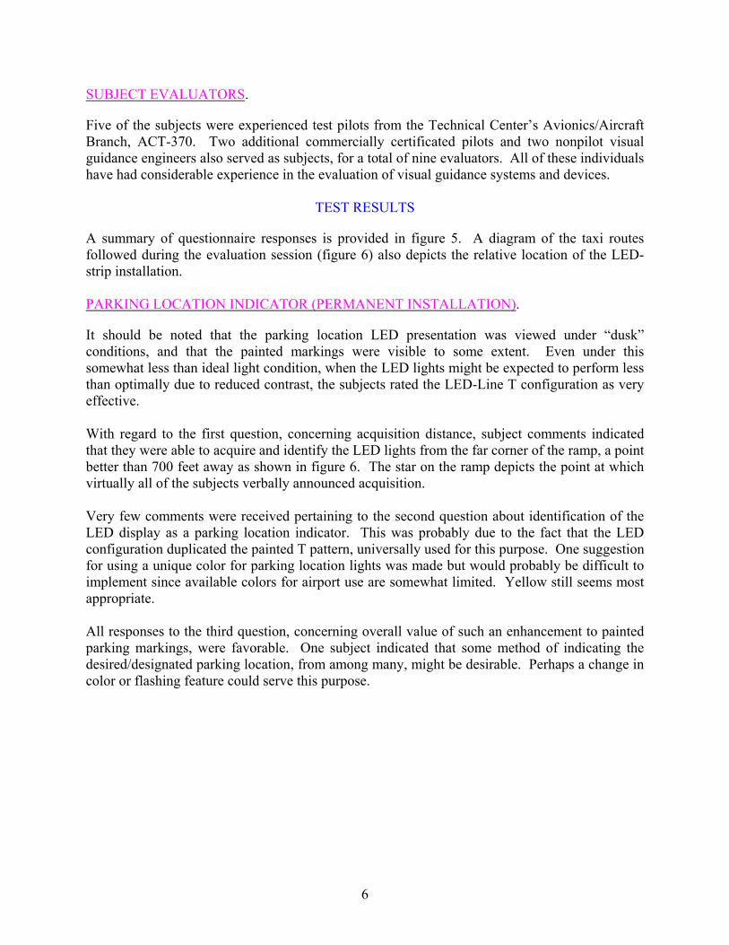
The test LED-strip configuration installed was in the form of a parking location �T� figure, purposely collocated with an existing painted marking of the same pattern (figure 2). It was comprised of five 3-m (10-foot) sections, or strips, forming the crossbar of the T and an additional nine sections forming the �tail� of the T. Each LED is rated at 1800 mcd at 70 mA, which equals 0.84 watts. The LEDs in the evaluation configuration were powered at 40 mA,
2

which produces 900 mcd and 0.48 watts. Each individual LED section contained 96 encapsulated LED devices (lights) in groups of four with 32-mm (1.25-inch) spacing between each LED (figure 3). All strips were installed in a saw-cut trench and temporarily supported during pouring of the surrounding sealant so that the top surface of each strip was approximately 2.5 mm (1/10 inch) below the surrounding concrete. Three 120Vac/12Vdc constant voltage power supplies were connected to the individual LED strips at both ends within the two five-strip and one four-strip grouping. Connections were made at both ends of all strips to provide redundancy in the event of an end connector failure. The end connectors, provided by the manufacturer and preinstalled at the factory, used spring-loaded contacts butted against the metallic ribbon conductor encapsulated with the LED lamps. This provided only minimum contact area between the feeder wires and the ribbon conductor and was a continuing problem until it was replaced with a more positive connector retrofit.
FIGURE 2. PARKING LOCATION INDICATOR LAYOUT
3

FIGURE 3. LED-STRIP SECTION PHOTOGRAPH Some difficulty was experienced with maintaining a constant level with the surrounding pavement within each strip due to what seemed to be excessive flexibility of the �U� channel provided to support the encapsulated LED lights. Even using closely spaced mounting templates, per the manufacturer�s instructions, it was necessary to add 1/2″ by 1/2″ angles underneath the channel for rigidity during installation in the saw-cut trench.
EVALUATION
PROCEDURE.
Once the installation had been completed, seven subject pilots and two visual guidance engineers were afforded the opportunity of evaluating the LED-strip parking locator presentation from a taxiing Convair 580 aircraft. Each subject was briefed on the purpose of the evaluation, the taxi
4

route to be followed, and the manner in which to indicate the point at which the LED display was first identified. Subjects also completed postsession questionnaires (see figure 4), giving their opinions as to the effectiveness of the LED-strip installation.
LED STRIP PILOT QUESTIONNAIRE Name:____________________ Date:_________ Weather:________________ ______________________________________________________________________________ CONFIGURATION (PARKING LOCATION) 1. Did you see and identify the LED strip lighting in time to easily execute your approach to the
parking spot?
Yes:_____ No:_____ (If �No�, please explain deficiencies) Comments:_________________________________________________________ ___________________________________________________________________ ___________________________________________________________________
2. Was the LED lighting presentation sufficiently clear that it identified the location for what it was � a parking position?
Yes:_____ No:_____ (If �No�, please explain deficiencies) Comments:_________________________________________________________ ___________________________________________________________________ ___________________________________________________________________
3. How would you rate this proposed addition/modification to painted surface markings?
Well worthwhile:_____ Marginal help:_____ Waste of money:_____
Comments:_________________________________________________________ ___________________________________________________________________ ___________________________________________________________________
FIGURE 4. SUBJECT EVALUATOR SAMPLE QUESTIONNAIRE
5
SUBJECT EVALUATORS.
Five of the subjects were experienced test pilots from the Technical Center�s Avionics/Aircraft Branch, ACT-370. Two additional commercially certificated pilots and two nonpilot visual guidance engineers also served as subjects, for a total of nine evaluators. All of these individuals have had considerable experience in the evaluation of visual guidance systems and devices.
TEST RESULTS
A summary of questionnaire responses is provided in figure 5. A diagram of the taxi routes followed during the evaluation session (figure 6) also depicts the relative location of the LED-strip installation. PARKING LOCATION INDICATOR (PERMANENT INSTALLATION).
It should be noted that the parking location LED presentation was viewed under �dusk� conditions, and that the painted markings were visible to some extent. Even under this somewhat less than ideal light condition, when the LED lights might be expected to perform less than optimally due to reduced contrast, the subjects rated the LED-Line T configuration as very effective. With regard to the first question, concerning acquisition distance, subject comments indicated that they were able to acquire and identify the LED lights from the far corner of the ramp, a point better than 700 feet away as shown in figure 6. The star on the ramp depicts the point at which virtually all of the subjects verbally announced acquisition. Very few comments were received pertaining to the second question about identification of the LED display as a parking location indicator. This was probably due to the fact that the LED configuration duplicated the painted T pattern, universally used for this purpose. One suggestion for using a unique color for parking location lights was made but would probably be difficult to implement since available colors for airport use are somewhat limited. Yellow still seems most appropriate. All responses to the third question, concerning overall value of such an enhancement to painted parking markings, were favorable. One subject indicated that some method of indicating the desired/designated parking location, from among many, might be desirable. Perhaps a change in color or flashing feature could serve this purpose.
6

LED STRIP PILOT QUESTIONNAIRE Name:_SUMMARY_____ Date:_3/13/99_ Weather:___CAVU_____ ______________________________________________________________________________ CONFIGURATION (PARKING LOCATION)
1. Did you see and identify the LED strip lighting in time to easily execute your approach to the parking spot?
Yes:__9__ No:__0__ (If �No�, please explain deficiencies) Comments:_________________________________________________________ ___________________________________________________________________ ___________________________________________________________________
2. Was the LED lighting presentation sufficiently clear that it identified the location for what it was � a parking position?
Yes:__9__ No:_0__ (If �No�, please explain deficiencies) Comments:_________________________________________________________ ___________________________________________________________________ ___________________________________________________________________
3. How would you rate this proposed addition/modification to painted surface markings?
Well worthwhile:__8__ Marginal help:__1__ Waste of money:__0_
Comments:_________________________________________________________ ___________________________________________________________________
FIGURE 5. QUESTIONNAIRE SUMMARY
7

8
LED Strip A c q uisitio n Po int(718 Fe e t Aw a y)
LED Strip Pa rking Sp o t
FIGURE 6. TAXI ROUTE AND DISPLAY LOCATIONS
GENERAL CONSIDERATIONS.
Several comments were received questioning how these LED displays might compare with reflective (beaded) paint markings. While it is generally acknowledged that beaded paint markings are more effective than unbeaded, one must remember that they must be within the beam of the aircraft lights (i.e., off the nose) to be useful. LED lights will provide guidance from all viewing angles and to pilots maneuvering through turns and curved routes. Conversely, during daylight conditions, the effectiveness of LED strips will be diminished considerably, while painted markings will be more effective. This emphasizes the fact that LED strips will serve best to enhance the existing painted markings at night and during wet surface (standing water) conditions, and not provide �stand alone� guidance. During the evaluation period, the LED strips were covered by approximately 1 1/2″ to 2″ of snow. It was verified that the strips were illuminated but were not visible under the snow. LED lights do not generate any appreciable heat so there will be virtually no chance that they will experience any self-cleaning or melting of the snow/ice covering. Snowplowing should not be a problem, since the LED strips are installed approximately 1/16″ to 1/8″ below the surrounding surface, but this will also result in a covering being left after plowing. Figure 7 shows a portion of the illuminated parking location display after a period of light snow.
LED Strip Parking Spot
LED Strip Acquisition Point (718 Feet Away)
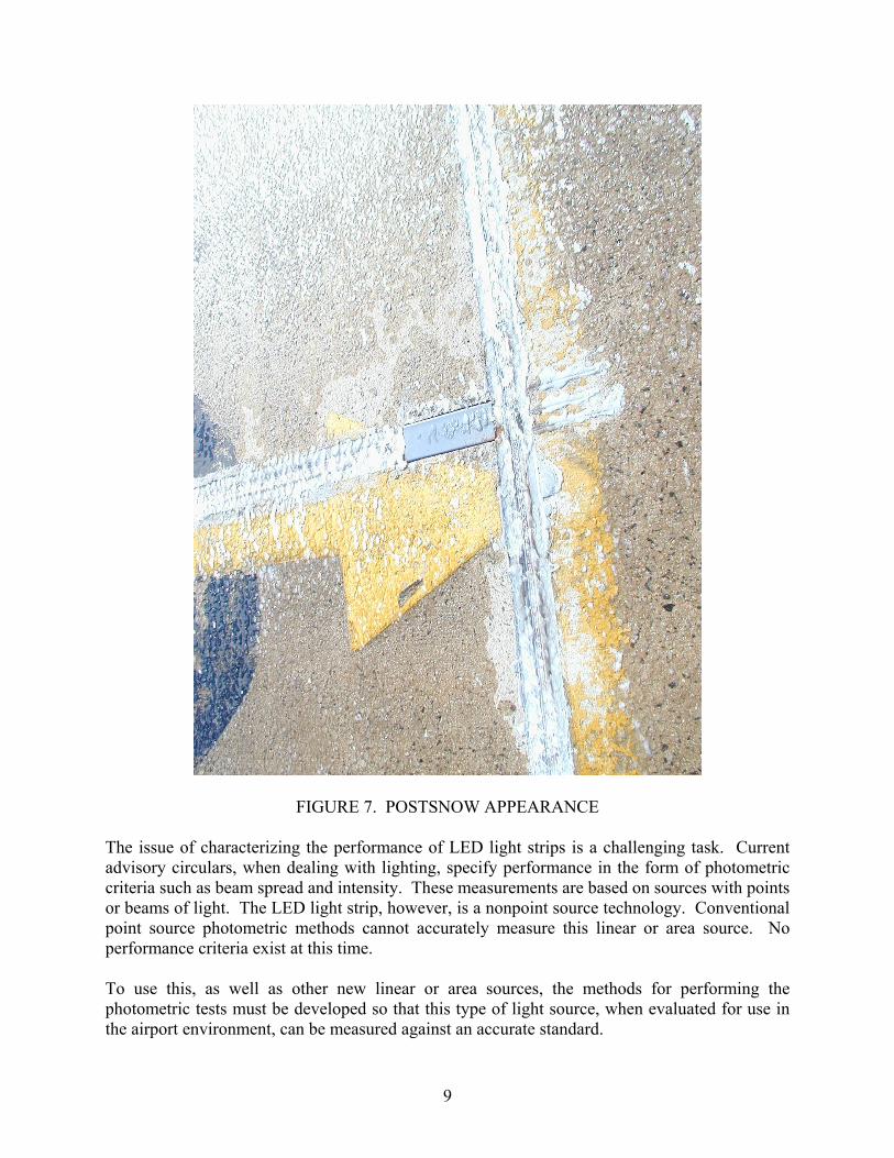
FIGURE 7. POSTSNOW APPEARANCE The issue of characterizing the performance of LED light strips is a challenging task. Current advisory circulars, when dealing with lighting, specify performance in the form of photometric criteria such as beam spread and intensity. These measurements are based on sources with points or beams of light. The LED light strip, however, is a nonpoint source technology. Conventional point source photometric methods cannot accurately measure this linear or area source. No performance criteria exist at this time. To use this, as well as other new linear or area sources, the methods for performing the photometric tests must be developed so that this type of light source, when evaluated for use in the airport environment, can be measured against an accurate standard.
9

MAINTENANCE.
During a period of approximately 6 months, the LED-strip parking position indicator was operated intermittently whenever visiting aircraft arrived. Almost all malfunctions or failures occurred because of the connector design mentioned earlier in this report. A gap between LED sections, of about 10 inches in length, was necessary to provide room for the connectors and for the connections with the feeder cables running beneath the LED strips (see figure 8). This void was filled with a solidified foam and protected with a U-shaped steel cover to protect the wiring and reduce water contamination. Unfortunately, the tops of the original sealed connectors protruded above the surface level of the LED strips. Under pressure from aircraft and vehicles passing over the covers, the connectors soon were bent downward, causing frequent separation of the spring-loaded butt connection. In some cases, a vehicle passing over a cover would cause a section to go out, while another vehicle subsequently passing over would cause the strip to be re-energized. The fact that each section was fed from both ends, also caused disconnections to go unnoticed until both connectors had failed.
FIGURE 8. CONNECTION SPACE BETWEEN LED SECTIONS After repeated failures, the original connectors were removed and replaced with screws inserted directly into the ends of the strips and contacting the ribbon conductor along the thread length. The feeder cables were then attached to the screws with ring connectors. This alternate connection method served well until such time as the screws rusted, breaking the contact once more.
10

There were no instances of individual LED-lamp failures. The encapsulation material and components contained therein appeared to have withstood the weight of passing vehicles well, and only at one point was any cracking or breaking noted.
RECOMMENDATIONS
As a result of the evaluation and testing accomplished thus far, it is recommended that: 1. The development of performance standards for this nonpoint source technology is needed
in order to publish appropriate advisory circulars/specifications. Photometrics procedures need to be developed to quantify this type of nonpoint source lighting.
2. Installation procedures need to be refined and standardized. 3. Equipment to be procured for future evaluation must be redesigned to better suite the
hostile airport environment. This pertains particularly to the method of connecting the LED strips to the feeder power cables.
4. Use of LED-strip lights to enhance movement area markings, such as at runway/taxiway
and taxiway/taxiway intersection holding positions, should be investigated. Except for the installation-related issues mentioned in this report, the LED-strip lighting installed at parking spot No. 1 has been in operation for 433 hours as of the date of this report. During this time, all who have viewed this installation have given only positive comments.
CONCLUSIONS
Operationally, the LED light strips do enhance airport paint markings. This technology can be acquired from a much farther distance than paint markings. Another major advantage of this technology is its nighttime visibility when covered with standing water, whereas paint markings become obliterated. On the issue of snow covering, however, this technology becomes obliterated the same as paint markings.
11/12