dot/faa/ar-97/56 applications of fracture mechanics to … · applications of fracture mechanics to...
TRANSCRIPT

DOT/FAA/AR-9 7/56
Office of Aviation Research Washington, D.C. 20591
Applications of Fracture Mechanics to the D urability of Bonded Composite Joints
May 1998
Final Report
This document is available to the U.S. public through the National Technical Information Service (NTIS), Springfield, Virginia 22161.
U.S. Department of Transportation Federal Av iation Adminis tration

NOTICE
This document is disseminated under the sponsorship of the U.S. Department of Transportation in the interest of information exchange. The United States Government assumes no liability for the contents or use thereof. The United States Government does not endorse products or manufacturers. Trade or manufacturer's names appear herein solely because they are considered essential to the objective of this report.
Technical Report Documentation Page
1.
DOT/FAA/AR-97/56
2. Government Accession No. 3.
4.
APPLICATIONS OF FRACTURE MECHANICS TO THE DURABILITY OF
5.
May 1998
BONDED COMPOSITE JOINTS 6.
7.
W. Steven Johnson, Lawrence M. Butkus, and Rodolfo V. Valentin
8.
9.
School of Material Science and Engineering George W. Woodruff School of Mechanical Engineering
10.
Georgia Institute of Technology Atlanta, GA 30332
11.
FAA Grant: 95G023 12.
U.S. Department of Transportation Federal Aviation Administration
13.
Final Report for the period of 26 April 1995 -25 October 1996
Office of Aviation Research Washington, DC 20591
14.
AAR-431 15.
Federal Aviation Administration William J. Hughes Technical Center Technical Monitor: D. W. Oplinger
16.
The increased numbers of bonded composite components and bonded repairs of cracked structures make knowledge of adhesive bonding crucial to aircraft design and lif e extension. This report covers an effort which focused on using fracture mechanics to evaluate the Mode I fracture and fatigue properties of several adhesively bonded aerospace material systems. The research concentrated on bond line cracking rather than fatigue crack growth in composite or metal adherends. Particular attention was paid to the environmental durability of bonded systems in use or intended for use on transport, fighter, and supersonic aircraft.
Analysis was performed using closed-form solutions as well as finite element analyses. esults were discussed with respect to their relevance and applicability to bonded joint design. Key results include the identif ication of significant degradation in some varieties of bonded joints subjected to long-term isothermal exposure under hot/wet conditions. he degradation was manifested by decreased fracture toughness and fatigue threshold levels.
Finite element analyses were performed on specimens with dissimilar adherends having complex geometries and thermally induced stresses in the bond line. case study in which finite element analyses were used to relate the experimental results from this program with those of an independent project is also included. he analyses highlight the importance of using tapered adherends to avoid fatigue failures and show that typical aircraft skin stresses are below experimentally obtained threshold values for the specimen geometries investigated.
Results of this study emphasize that the environmental durability of adhesively bonded joints is a key issue which must be considered by aerospace design engineers.
17.
Adhesive durability , Fracture mechanics, Crack growth, Finite element analysis, Adhesive testing
18.
This document is available to the public through the National Technical Information Service (NTIS), Springfield, Virginia 22161.
19.
Unclassified
20.
Unclassified
21.
60
22.
N/A
Report No. Recipient's Catalog No.
Title and Subtitle Report Date
Performing Organization Code
Author(s) Performing Organization Report No.
Performing Organization Name and Address Work Unit No. (TRAIS)
Contract or Grant No.
Sponsoring Agency Name and Address Type of Report and Period Covered
Sponsoring Agency Code
Supplementary Notes
Abstract
R
T
AT
Key Words Distribution Statement
Security Classif. (of this report) Security Classif. (of this page) No. of Pages Price
Form DOT F1700.7 (8-72) Reproduct ion of com pleted page aut horiz ed

ACKNOWLEDGMENTS
The authors wish to acknowledge the support and encouragement provided by the FAA Technical Monitor Mr. D. W. Oplinger during this effort. In addition, the assistance received from the following people during the performance of this research program is acknowledged:
Mr. Richard Brown Georgia Institute of TechnologyMr. Bob Bell and Ms. Carol Burke Lockheed Martin, C-141 ProgramMr. Scott Reeve Lockheed Martin, F-22 ProgramMr. David Schneider Lockheed MartinMr. Kevin Pate Boeing Defense and Space Group, HSCT ProgramMr. Tuan Cao Boeing Defense and Space GroupMr. Richard Simms and Mr. Jerry Rowell Robins AFB, GAProf. B. Dattaguru Indian Institute of Science - Bangalore
iii/iv

TABLE OF CONTENTS
Page
EXECUTIVE SUMMARY
1. INTRODUCTION
1.1 Program Overview1.2 Historical Perspective
2. DESIGN PHILOSOPHY
2.1 Previous Research
ix
1
1 2
4
4 2.2 A Fracture Mechanics Approach to Durability 8
3. MATERIALS AND EXPERIMENTAL PROCEDURES 11
3.1 Materials 11
3.1.1 Adhesives 11
3.1.1.1 FM®73M 113.1.1.2 AF-191 123.1.1.3 FM®x5 12
3.1.2 Bonded Specimens 12
3.1.2.1 C-141 Bonded Systems 14
3.1.2.1.1 Aluminum Bonded to Aluminum (Al/FM®73M/Al) 143.1.2.1.2 Aluminum Bonded to Boron-Epoxy (Al/FM®73M/Al) 14
3.1.2.2 F-22 Bonded Systems 153.1.2.3 High-Speed Civil Transport (HSCT) Bonded System 15
3.2 Specimen Geometry 153.3 Environmental Conditioning 16
3.3.1 Isothermal Exposure 163.3.2 Cyclic Thermal Exposure 17
3.4 Testing Procedures 19
3.4.1 Fracture Toughness (Monotonic) Testing Procedures 213.4.2 Fatigue Testing Procedures 21
4. ANAL YTICAL PROCEDURES 22
v
4.1 Closed-Form Solution for the Mode I Strain Energy Release Rate (GI) 224.2 Finite Element Analysis 24
4.2.1 Programs 244.2.2 Assumptions and Model Details 244.2.3 Determination of Strain Energy Release Rate 254.2.4 Verification of Analysis 264.2.5 Analysis of the Curved Al/FM®73M/B-Ep Specimens 26
5. RESULTS AND DISCUSSION 27
5.1 Environmentally Induced Physical Changes 275.2 Al/FM®73M/Al 28
5.2.1 Fracture Toughness 285.2.2 Crack Path and Fracture Surfaces 295.2.3 Fatigue Crack Growth 30
5.3 Al/FM®73M/B-Ep 31
5.3.1 Finite Element Analysis of the Al/FM®73M/B-Ep System 315.3.2 Fracture Toughness5.3.3 Crack Path and Fracture Surfaces5.3.4 Fatigue Crack Growth
5.4 Gr-BMI/AF-191/Gr-BMI
5.4.1 Fracture Toughness5.4.2 Crack Path and Fracture Surfaces5.4.3 Fatigue Crack Growth
5.5 Ti/FM®x5/Ti
5.5.1 Fracture Toughness5.5.2 Crack Path and Fracture Surfaces5.5.3 Fatigue Crack Growth
6. CASE STUDY
6.1 The Textron/Boeing Project6.2 Finite Element Model6.3 Results and Discussion
7. SUMMARY AND CONCLUSIONS
8. REFERENCES
32 33 34
34
35 35 36
37
37 38 39
39
40 41 43
45
47
vi

LIST OF FIGURES
Figure Page
1 Mode Fracture Toughness of Several Matrix and Adhesive Systems 6
2 Relation Between Total Strain Energy Release Rate and Debond Growth Rate forBonded Composite Joints Using FM®300 and EC-3445 Adhesives 7
3 Effect of Taper Angle on Joint Performance for Bonded Composite Joints 8
4 Possible Environmental Effects on the (a) Fracture Toughness and (b) Fatigue CrackGrowth Behavior of Adhesively Bonded Joints 9
5 Environmental Exposure Effects May Require Design Changes to Meet OperatingRequirements 10
6 Scrim Cloths Contained in the (a) FM®73M, (b) AF-191, and (c) FM®x5 Adhesives 12
7 Geometry for the Various Double Cantilever Beam Specimens 13
8 Thermotron Air Circulating Aging Oven Used for Long-Term Isothermal Exposure 16
9 Humidity Chamber Used to Maintain a Hot/Wet Environment 17
10 Thermal Cycling Unit Located at Robins AFB, GA 18
11 Thermal Cycle Temperature Profiles 19
12 Double Cantilever Beam Specimen Being Loaded in a Servohydraulic Test Machine 20
13 Load Versus Displacement Data From Several Runs Performed on a Single Specimen 21
14 Determination of the End Correction Term, Δ 23
15 The Modified Crack Closure Technique (Model is of Unit Width) 25
16 A Comparison of Load Versus Displacement Data Obtained Experimentally andComputed Using the ABAQUS Finite Element Program 26
17 Weight Changes of Specimens Subjected to Long-Term Isothermal Exposure 28
18 Mode I Fracture Toughness of the Al/FM®73M/Al Bonded System 29
19 Fracture Surfaces of the Al/FM®73M/Al Bonded System (As Received) 29
vii

20 Mode I Fatigue Crack Growth Behavior of the Al/FM®73M/Al Bonded System 30
21 Computed Mode I, Mode II, and Total Applied Strain Energy Release Rates for an Al/FM®73M/B-Ep Specimen as a Function of Load for a Single Crack Length 32
22 Fracture Toughness of the Al/FM®73M/B-Ep Bonded System 33
23 Fracture Surfaces of the Al/FM®73M/Al Bonded System (As Received) 33
24 Fatigue Crack Growth Behavior of the Al/FM®73M/B-Ep Bonded System 34
25 Mode I Fracture Toughness of the Gr-BMI/AF-191/Gr-BMI Bonded Systems 35
26 Fracture Surfaces of the Gr-BMI/AF-191/Gr-BMI Bonded Systems (As Received), Upper Photo: Unidirectional Adherend, Lower Photo: Quasi-Isotropic Adherend 36
27 Mode I Fatigue Crack Growth Behavior of the Unidirectional GR-BMI/AF-191/GR-BMI Bonded System 37
28 Fracture Toughness of the Ti/FM®x5/Ti Bonded System 38
29 Fracture Surfaces of the Ti/FM®x5/Ti Bonded System (As Received) 38
30 Mode I Fatigue Crack Growth Behavior of the Ti/FM®x5/Ti Bonded System 39
31 The Textron/Boeing Fatigue Test Specimen 40
32 Model of the Textron/Boeing Fatigue Test Specimen 41
33 Grip Conditions Used in Modeling the Textron/Boeing Experiments 42
34 Strain Energy Release Rates Produced by Stresses Applied to the Textron/Boeing Specimen 44
LIST OF TABLES
Table Page
1 Summary of Current Operational Bonded Boron-Epoxy Repairs 4 2 Isothermal Exposure Summary 17 3 Summary of Thermal Cycling Parameters for Bonded-Joint Specimens 19 4 Material Properties Used for the Model of the Textron/Boeing Specimen 41
viii
EXECUTIVE SUMMARY
With the increase in the number of bonded composite aircraft components and in the number of bonded repairs made to cracked metallic structures, knowledge of adhesive bonding is becoming crucial to aircraft design and life extension. Design and analysis of adhesively bonded joints has traditionally been performed using a variety of stress-based approaches. The use of fracture mechanics has become increasingly popular for the analysis of metallic components but has seen limited use in bonded structure joints. Durability and damage tolerance guidelines, already in existence for metallic aircraft structures, need to be developed for bonded structures, and fracture mechanics provides one method for doing so.
This report covers an FAA-sponsored research program performed at the Georgia Institute of Technology which has focused on using fracture mechanics to evaluate the Mode I fracture and fatigue properties of several adhesively bonded aerospace material systems. This research has concentrated on the behavior of cracks or debonds in the adhesive bond line rather than damage in the composite or metallic adherends. Particular attention has been paid to the environmental durability of bonded systems in use or intended for use on transport, fighter, and supersonic aircraft.
This study encompassed experimental fracture and fatigue testing as well as finite element analyses. Elements of a philosophy for bonded joint design were also formulated.
Key results from the experimental program include the identification of significant degradation in some varieties of bonded joints subjected to long-term exposure to high-temperature and high-humidity conditions. Such degradation was displayed in terms of losses in fracture toughness under monotonic loading and in a reduction of the fatigue threshold. Similar, though less severe, losses were experienced by some bonded systems following exposure to thermal cycling.
Finite element analyses were needed to evaluate experimental results, which were in close agreement. The use of finite element programs was also necessary to analyze specimens with complex geometries and thermally induced residual stresses in the bond line. These analyses provided insights into the relationship between residual stress states and the fracture and fatigue properties of these systems.
Experimental and finite element results generated for this project were also compared with an independent study of the fatigue behavior in the case of a composite patch on an aluminum substrate. Results of this comparative study were consistent with observations from the Georgia Institute of Technology experimental program and highlighted the importance of using tapered adherends to avoid fatigue failures. In addition, it was found that typical aircraft structural stresses were far below experimentally obtained threshold values for the particular geometries investigated.
The environmental durability of adhesively bonded joints is a key issue to be considered by aerospace design engineers. Effects of long-term isothermal and thermally cycled exposure to specific environments can be detrimental to adhesive joint performance in terms of reduction in fracture toughness and fatigue threshold. The study described in the following report sought to address a representative sample of these important concerns.
ix/x

1. INTRODUCTION.
1.1 PROGRAM OVERVIEW.
The goal of this program was to assess the durability of bonded composite joints using fracture mechanics. Fracture mechanics (section 1.2) and stress-based techniques have been used to analyze and design bonded joints in previous studies. These methods will be reviewed in section 2. The current research program aimed at expanding the use of fracture mechanics to address the issue of the environmental durability of bonded joints while recognizing the merit and applicability of stress-based approaches
To attain the goal of this program, several objectives were identified. These include the characterization of fracture and fatigue behavior of several adhesive joint systems, the quantification of degradation due to environmental exposure, and the development of a methodology to assess the structural integrity of bonded joints. These objectives served to guide the research described in the following report.
Motivation for this project came from several directions, the primary focus being on bonded structures for aerospace use.
First, a desire exists to supplement current stress-based approaches to bonded joint design. Although stress-based methods have proven their worth over the last several decades, fracture mechanics offers an alternate, equally viable means of analysis.
Second, impetus for this research also came from a need to link knowledge of environmental effects with the fracture and fatigue characteristics of bonded joints. As bonding becomes more prevalent and aircraft design lives lengthen, understanding, in general terms, the interaction of the operating environment with material properties becomes increasingly crucial. In addition, several organizations, including the Federal Aviation Administration; the U.S. Air Force; and major airframe manufacturers, have concerns about the performance of specific adhesively bonded systems.
Finally, this research was undertaken to respond to the recently increased emphasis for life extension of aging aircraft. This emphasis has highlighted the need for addressing the durability of bonded composite repairs to existing cracked metallic components as well as the projected lifetimes of bonded structures in future aircraft designs. Understanding the behavior of adhesive joints subjected to various environmental conditions serves as the basic motivating factor for this research and for the eventual development and refinement of durability and damage tolerance guidelines for bonded aerospace structures.
Characterizing the fracture and fatigue behavior of bonded joints generally employs pre-existing cracks or defects in the bond line region. These cracks are artificially introduced and are intended to simulate damage to, or flaws in, the bond line which may occur during fabrication or operation of adhesively bonded components. Thus, the focus of this research was on the propagation of cracks rather than on their initiation. Fatigue studies used the concept of a threshold level (defined as 1 x 10⁻⁶ mm/cycle [1 x 10⁻⁸ in/cycle]) to describe crack growth during
1

cyclic loading. The authors have used the terms crack and debond synonymously to describe fracture in the bond line region. When necessary, a more detailed description of the location of fracture (i.e., cohesive [within the adhesive layer] versus adhesive [at an adhesive/adherend interface]) is provided.
This report summarizes experimental and analytical studies and also addresses the design of bonded joints from a conceptual standpoint. As part of the experimental effort, monotonic and cyclic loading tests were performed on double cantilever beam (DCB) specimens constructed of several combinations of adhesives and composite and metallic adherends indicative of present and future bonded aerospace structures. These tests were conducted before and after subjecting specimens to environmental exposures which paralleled actual service conditions. Finite element analyses were also carried out to supplement the experimental efforts and to compare data generated in this project with results obtained from an independent study of bonded repair fatigue behavior.
This report is subdivided into seven sections. Section 1 serves as the introduction and summarizes the use and analysis of adhesively bonded joints from a historical perspective. Section 2 reviews previous work in the design of bonded joints and sets forth a fracture mechanics approach to durability. Section 3 reviews the materials and experimental procedures used in the experimental work. Closed-form and finite element analyses are described in section 4. Section 5 summarizes and discusses the experimental results. A case study, in which the research for this program is related to an independent study, forms the basis for section 6. The summary and conclusions are presented in section 7.
1.2 HISTORICAL PERSPECTIVE.
Adhesive bonding of aerospace components is a fabrication technique which, though over 70 years old, has increased markedly in popularity during the last two decades and is currently a focal point in many studies regarding aging aircraft. Military applications of adhesive bonding began in the early days of flight and during World War I. Significant breakthroughs such as the use of phenolic resins in wood and wood-to-metal joints occurred during the World War II era on aircraft such as the RAF’s Mosquito. Building upon these advances, engineers at Fokker began bonding structural metal components on the successful F-27 and F-28 series in the late 1940’s and early 1950’s. [1, 2] Military use of bonded metal structures occurred almost simultaneously on aircraft like the USAF’s B-58 Hustler. [3]
A highly successful program investigating bonding for use in joining metal aircraft components was the Primary Adhesively Bonded Structures Technology (PABST) program [4, 5] sponsored by the USAF in the late 1970’s. This program’s results confirmed and expanded the list of advantages offered by properly manufactured adhesive bonds compared to riveted assemblies. This list of strong points includes reduced weight, increased fatigue resistance, improved sealing capabilities, more efficient aerodynamics and, often, reduced costs.
These advantages have also spurred the use of adhesive bonding for joining polymer matrix composite aircraft components. Due to the possibility of cocuring and the brittle nature of
2

composite parts, adhesive bonding is well-suited for joining composites to composites and composites to metals, as well. Military applications initiated the first use of adhesively bonded advanced composites, and aircraft such as the F-18 and the future F-22 employ significant amounts of bonded polymer matrix composite laminates for wing skins and control surfaces. Similar applications may be found on many types of commercial aircraft whose economic operations benefit considerably from the reduced weight offered by bonded composite assemblies. However, due to past difficulties with surface preparation and associated troubles with environmental durability, adhesive bonding has not become widespread in the aircraft industry. [1]
Coincident with the use of bonds for structural fabrication, advances in repair technology and an increased emphasis on extending the lifetimes of aging aircraft have generated a great deal of interest in the use of adhesives for repairs. In fact, the use of adhesively bonded composite repairs of metal structures is currently the focus of as many research and development efforts as the bonding of primary structural composites, and perhaps more. Pioneering work in Australia [6] and the U.S. [7] has resulted in broad usage of bonded repairs on military aircraft. There is also growing interest in their application to commercial aircraft, as exemplified by recent FAA supported research and development efforts on use of composites for door corner reinforcement of an L1011 aircraft, and assessment of bonded repairs of metal structure by McDonnell Douglas. Although carbon fiber reinforced composites [8] and GLARE laminates [9] have been employed in bonded repairs of metals, the most common bonded repair system for metals consists of a boron-epoxy composite laminate bonded to an aluminum airframe using a rubber toughened epoxy adhesive. Though no exhaustive survey exists of all bonded aircraft repairs, an estimated 6500 boron-epoxy patches are in worldwide use on military aircraft and over 200 have been applied to commercial aircraft. [10] Table 1 shows a brief synopsis of some of the many bonded boron-epoxy repairs in use. The most prevalent use of this technique has been the repair of nearly 500 fatigue cracks emanating from wing skin fuel transfer holes (weepholes) on the USAF C-141 fleet. [11] The primary advantage offered by these repairs is a significant reduction in crack growth in the underlying metallic structure. This problem has been studied extensively, [12, 13, 14] resulting in the well documented reduction in stress levels and Δ K at the crack tip together with the increase in patched component life.
Despite prior successes in wood, metal, and composite bonded joints and repairs, questions still remain regarding the durability and damage tolerance of the adhesive bond line, the critical region upon which the integrity of the bonded repair or assembly depends. Though dimensionally small compared with the adherends, the bond line contains not only the adhesive but also interphase regions and is the crucial component of any bonded structure, regardless of the adherend materials. Thus, understanding the effect of defects and service environments on the adhesive is necessary for assessing the long-term performance of bonded structures. This issue is of critical importance in the current climate of extending the lives of existing aircraft and of creating new designs intended for operational periods measured in decades rather than in years.
3

TABLE 1. SUMMARY OF CURRENT OPERATIONAL BONDED BORON-EPOXY REPAIRS [6, 15, 16]
Owner Aircraft Component Number of
Aircraft Number of
Patches Date
MILITARY
United States Air
Force (USAF)
Lockheed C-141 Wing Skin ~150 ~500 1993-94
General Dynamics F-111 Wing Pivot 411 ~800 1973-83
Rockwell B-1 Dorsal Longeron 96 ~190 1991-96
Lockheed C-5 Fuselage 1 2 1996
Lockheed C-130 Gear Door 1 1 1992
Northrop T-38 Access Door 3 4 1994
Royal Australian Air Force (RAAF)
General Dynamics F-111 Wing Pivot, Skin
~1500 total 1975-96Lockheed C-130 Wing Stiffener
Mirage III Wing and Tail Skin
Macchi Wheel
Royal Air Force
(RAF)
Hawk Wing Skin 1 1 1993
Harrier Fuselage 1 1 1993
Royal Canadian Air Force (RCAF)
Northrop F-5 Wing Skin ~25 ~50 1992-97
Dutch Air Force General Dynamics F-16 Wing Skin ~3 ~3 1996
COMMERCIAL
Air Inter (France) Dassault Mercure Door Frames 11 ~100 1973-78
Ansett (Australia) Boeing 767 Keel Beam 1 2 1989
BAE 146 Engine Cowl 1 6 1992
Qantas Boeing 747 Various decals† 1 9 1990
Australian Airlines Boeing 727 Fuselage decals† 1 9 1989
Boeing Boeing 747-SR Various 1* 11 ~1989
Boeing 747-400 Various 1* 13 1990
Air Wisconsin BAE 146 Engine Cowl 1 6 1992
Federal Express Boeing 747-200 Various decals† 2 25 1993
* indicates static test airframe † decals are patches applied to uncracked structure to test durability
2. DESIGN PHILOSOPHY.
2.1 PREVIOUS RESEARCH.
Previous research in the field of bonded joint analysis and design may be grouped into two major areas of emphasis. The first, a stress-based approach, was initiated by Goland and Reissner [17] and has been used extensively by Hart-Smith [5], Hart-Smith and Thrall [18], and others. This approach has focused on determining the distribution of shear and normal (or peel) stresses within the adhesive bond line under static loading conditions. In their seminal work, Goland and Reissner investigated single lap shear joints with thin (inflexible) and thick (flexible) adhesive layers. Their results indicated that both shear and normal stresses approach maxima at or near
4

the free edge of the joint. Adams [19] confirmed this observation and, using a finite element analysis, proposed that failure of the adhesive layer occurs in tension due to high peel stresses rather than in shear as suggested by the lap shear joint’s name. Because of the importance of the peel stresses, they have been incorporated into bonded joint design and current criteria call for their elimination or drastic reduction. [4, 5, 18] The presence of stress concentrations at the edges of a joint combined with a lightly loaded though useful region of adhesive at the center has led to techniques, such as increased overlaps and tapered adherends, which reduce the magnitude of the near-edge stresses. In addition, several stress-based failure criteria have been proposed. One of the most notable is Hart-Smith’s approach [20] which states that bond strength is limited by the adhesive’s shear strain energy per unit bonded area. To date, the stress-based approach to bonded joint design has functioned well, has been incorporated into computerized design programs used in the aerospace industry, and has contributed to the success of the USAF’s PABST program and subsequent adhesively bonded designs.
However, in order to more accurately evaluate the effects of bond line flaws and fatigue, a second, parallel approach to the examination of bonded joints based on the principles of fracture mechanics has emerged. Founded upon the basic theories developed by Griffith and Irwin, the use of fracture mechanics for bond analysis was first proposed by Ripling, Mostovoy, and Patrick. [21] At the time of their research, the stress-intensity factor, K, had become accepted for describing fracture in metals. However, the use of K is based upon homogeneous materials and requires difficult stress analyses if H is to be applied to heterogeneous systems. Ripling et al. [21] recognized the inhomogeneity of bonded systems and proposed the use of the more fundamental strain energy release rate, G, to replace K in describing fracture of adhesive joints. The use of current K solutions also depends upon the full development of a plastic zone ahead of the crack tip. In adhesive joints, the plastic zone in the adhesive layer is often restricted by the adherends. Shaw [22] investigated this phenomenon and used it to further reinforce the choice of an energy (G) approach rather than a stress intensity (K) approach for describing the fracture behavior of bonded joints. A number of specimens have since been developed to investigate the Mode I, II, and/or III f racture and fatigue behavior of adhesively bonded joints. The most common is the double cantilever beam (DCB) which tests the resistance to Mode I cracking. Mixed-mode (rather than pure shear) behavior, which most closely parallels the loading on joints in service, may be addressed using specimens such as the cracked lap shear (CLS) specimen developed by Brussat et al. [23] and the mixed-mode bending (MMB) test designed by Reeder and Crews. [24]
Using the concept of fracture mechanics and the specimen geometries previously described, Johnson and colleagues in a series of articles [25-28] addressed the specific problems of fatigue and fracture in bonded composite materials. Some of their conclusions are summarized in the following paragraphs.
In an effort to assess the fracture behavior of common bonded composite systems, Johnson and Mangalgiri [25] investigated the static toughness of seven adhesive and polymer matrix resins used in fiber reinforced composites. Results from their research, shown in figure 1, illustrate a wide distribution of fracture toughness values ranging from those of relatively brittle systems such as the Hercules 3501-6 and Narmco 5208 epoxy matrix resins to that of Hexcel’s F-185
5

rubber-modified epoxy adhesive. Figure 1 indicates a type of performance envelope for the Mode I, Mode II, and mixed-mode failure of the polymer systems examined. Note that toughness or energy required to cause fracture under Mode II shear conditions (GIIc) is typically higher than that required under Mode I peel conditions (GIc). In addition to the constraining effects of the adherends investigated by Shaw, the authors proposed that this inequality could be based upon the polymer structure. They suggested that the relatively lower Mode I toughness values of many of the more brittle polymers may have been due to a high degree of cross-linking resulting in an inability to sufficiently deform plastically or to dilatate (increase in volume). Since the ability to dilatate is necessary for the development of Mode I toughness but not for Mode II (shear) toughness, the more brittle polymers, therefore, exhibited Mode I values which were lower than their Mode II values. In contrast, the more ductile polymers (F-185 and PEEK) exhibited much higher Mode I toughnesses than the brittle systems. Furthermore, the authors suggested that environmental exposure to heat and/or moisture may affect one mode of toughness to a greater extent than another mode, depending upon the effect that the exposure has on the polymer structure.
FIGURE 1. MODE FRACTURE TOUGHNESS OF SEVERAL MATRIX AND ADHESIVE SYSTEMS [25]
To investigate the fatigue crack growth or cyclic debonding characteristics of bonded composite joints, Johnson and Mall [26] employed the CLS specimen geometry. In fatigue tests on Narmco T300/5208 graphite reinforced composites bonded with FM®300 (American Cyanamid) and EC-3445 (3M Corp.) rubber-modified epoxies, the authors developed da/dN versus Gtotal (GT) curves similar to the da/dN versus Δ K relationships used to describe fatigue in metals (figure 2). Correlation between da/dN and GT was good despite the use of different adherend thicknesses as denoted by the thick- and thin-strap data in figure 2. With the selection of a threshold crack growth rate of 10-6 mm/cycle (3.94 x 10⁻⁸ in/cycle), their work also confirmed earlier findings indicating that static fracture toughness values far exceeded the threshold strain energy release rates (GT,th) required for debond growth in bonded composites. [28] In comparing figures 1 and 2, it can be seen that GT,th values are approximately 10% of the static toughness values for the
6

two adhesives examined. Finally, the fatigue studies also revealed that the slopes of the crack growth curves (indicated in figure 2 by n) for adhesive bonds are much higher than those for metals. This indicates that adhesive bonds have a greater sensitivity to small changes in the applied strain energy release rate making bond line crack growth rates less predictable under conditions of variable loading.
FIGURE 2. RELATION BETWEEN TOTAL STRAIN ENERGY RELEASE RATE AND DEBOND GROWTH RATE FOR BONDED COMPOSITE JOINTS USING FM®300 AND EC-3445 ADHESIVES [26]
Johnson and Mall [26] also examined the effect of tapered adherends on the fatigue crack growth behavior of the CLS specimens. Tapering was shown by Hart-Smith [5] to drastically reduce the peel stresses present at the joint ends and thereby enhance the strength of bonded structures. A 5° taper was believed to reduce peel stresses to such an extent that debonding would be eliminated. However, though Johnson and Mall found that tapering improved the fatigue resistance of bonded joints, debonding was not completely eliminated even with a taper angle as shallow as the recommended 5°. A summary of their results is given in figure 3 [26] which includes experimental data and predictions using the Geometric and Nonlinear Analysis of Structures (GAMNAS) [29] finite element program. By reducing the taper angle from 90° (no taper) to 5°, it was found that the stress required to reach the threshold strain energy release rate level (GT,th) was increased by approximately 50% and that most of the improvement came with taper angles below 10°. Tapered adherends carry more load than untapered adherends and adhesives with lower GT,th values can be substituted for those with greater GT,th values for a given joint loading. Changes in the taper angle may also serve to offset the effects of environmental exposure. This subject will be briefly discussed in the following section.
7

FIGURE 3. EFFECT OF TAPER ANGLE ON JOINT PERFORMANCE FOR BONDED COMPOSITE JOINTS [26]
The several studies previously described illustrate that the use of fracture mechanics has definite merit in assessing the behavior of bonded composite joints. In particular, it supplements and compliments stress-based analyses by adequately describing static toughness and fatigue crack growth characteristics.
2.2 A FRACTURE MECHANICS APPROACH TO DURABILITY.
Design of metal aerospace components has successfully integrated static and yield strength analyses with fracture mechanics to accommodate various philosophies including safe life, fail safe, durability, and damage tolerance. The design of bonded composite structures and structural repairs to existing metallic structures can also benefit from the use of both stress-based and fracture mechanics approaches. However, in order to fully understand the durability of bonded joints, the effect of operating environments on the fatigue and fracture properties of the adhesive must also be known. Groundwork has been laid by the investigators previously mentioned and by studies of the effects of various environments on some adhesive properties, but needs still exist to address the performance of specific adherend-adhesive combinations and to combine environmental, fatigue, and fracture studies of bonded systems.
For example, it is known that moisture absorption results in varying degrees of plasticization, strength loss, and increased ductility of some epoxy adhesives. However, the effect of moisture on the fatigue and fracture properties of bonded joints employing these adhesives is still not fully understood. In addition, since adhesive joints are systems comprised of adherends, adhesives, and inter-phase regions, the performance of each of these components may strongly affect the performance of the joint. Thus, general knowledge of the behavior of adhesives exposed to various environments must be supplemented by knowledge of the behavior of specific bonded systems.
In reviewing some of the trends observed in references 25 to 28 by Johnson and colleagues for room temperature behavior of as-received bonded composite specimens, it appears that
8
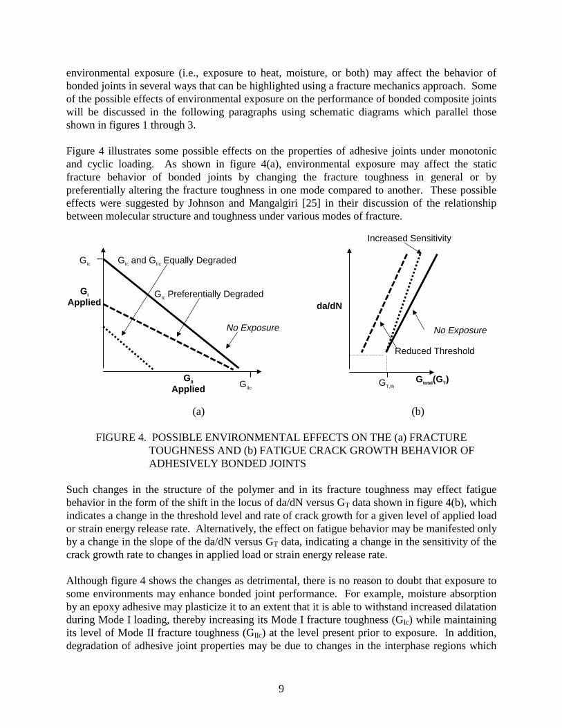
environmental exposure (i.e., exposure to heat, moisture, or both) may affect the behavior of bonded joints in several ways that can be highlighted using a fracture mechanics approach. Some of the possible effects of environmental exposure on the performance of bonded composite joints will be discussed in the following paragraphs using schematic diagrams which parallel those shown in figures 1 through 3.
Figure 4 illustrates some possible effects on the properties of adhesive joints under monotonic and cyclic loading. As shown in figure 4(a), environmental exposure may affect the static fracture behavior of bonded joints by changing the fracture toughness in general or by preferentially altering the fracture toughness in one mode compared to another. These possible effects were suggested by Johnson and Mangalgiri [25] in their discussion of the relationship between molecular structure and toughness under various modes of fracture.
No Exposure
Reduced Threshold
Increased Sensitivity
Applied
GII
No Exposure
GIc Preferentially Degraded
GIc and GIIc Equally DegradedGIc
GI
da/dN
Applied GIIc GT,th
Gtotal(GT)
(a) (b)
FIGURE 4. POSSIBLE ENVIRONMENTAL EFFECTS ON THE (a) FRACTURE TOUGHNESS AND (b) FATIGUE CRACK GROWTH BEHAVIOR OF ADHESIVELY BONDED JOINTS
Such changes in the structure of the polymer and in its fracture toughness may effect fatigue behavior in the form of the shift in the locus of da/dN versus GT data shown in figure 4(b), which indicates a change in the threshold level and rate of crack growth for a given level of applied load or strain energy release rate. Alternatively, the effect on fatigue behavior may be manifested only by a change in the slope of the da/dN versus GT data, indicating a change in the sensitivity of the crack growth rate to changes in applied load or strain energy release rate.
Although figure 4 shows the changes as detrimental, there is no reason to doubt that exposure to some environments may enhance bonded joint performance. For example, moisture absorption by an epoxy adhesive may plasticize it to an extent that it is able to withstand increased dilatation during Mode I loading, thereby increasing its Mode I fracture toughness (GIc) while maintaining its level of Mode II fracture toughness (GIIc) at the level present prior to exposure. In addition, degradation of adhesive joint properties may be due to changes in the interphase regions which
9

control the strength of the adhesive and adherend bonds. In this case, the adhesive may not be directly affected by the environment at all, but the interphase region may be weakened to an extent that it becomes the strength- or fatigue-limiting constituent of the joint. The importance of these possible trends in fracture toughness and crack growth behavior is crucial to designers for it is their task to ensure the integrity of a bonded joint over the life of the structure. Knowledge of these trends may result in the use of so called “knockdown” factors to limit the loads applied to affected joints or in alterations in the geometric designs of the joints.
In order to compensate or design for changes in the fatigue and fracture performance of a composite joint due to environmental exposure, measures might be taken such as those shown in figure 5. Figure 5 illustrates, for a case where exposure has shifted the crack growth threshold, that environmental effects may also force design modifications to achieve a desired design lifetime for a given cyclic stress level. Such modifications may reduce the total applied strain energy release rate, GT, perhaps through changes in the adherend taper angle. For the case where one mode of toughness is preferentially attacked, other design changes may permit a bonded joint to be loaded in a manner that better exploits its less degraded properties. In any case, knowledge of the way in which the environment affects a joint’s fatigue and fracture properties will lead to improved designs.
Δ S Applied Cyclic Stress
No Exposure
Gtotal or Taper Angle (α )
Original Design
Operating Stress
Reduced Performance Due to Exposure
(Curves Indicate Design Life)
Modified Design to Accommodate Environmental Effects
FIGURE 5. ENVIRONMENTAL EXPOSURE EFFECTS MAY REQUIRE DESIGN CHANGES TO MEET OPERATING REQUIREMENTS
To design efficient, effective, and durable bonded composite joints, it is necessary to determine the effect of service environments on the adhesive properties examined by stress-based and fracture mechanics approaches. Changes in strength, preferred mode of fracture, and crack growth behavior during long-term exposures will all affect the design of bonded joints used for structural and repair purposes. Through the use of stress analyses to ensure adequate static strength, fracture mechanics and fatigue analyses to ensure adequate damage tolerance, and
10

environmental studies to ensure adequate long-term durability, adhesively bonded aircraft joints and repairs can be designed and fabricated to meet the increasingly stringent requirements for extended aircraft lifetimes.
3. MATERIALS AND EXPERIMENTAL PROCEDURES.
Experimental efforts supporting this FAA-sponsored research project at the Georgia Institute of Technology focused on the Mode I fracture and fatigue behavior of several bonded joint systems. These adherend/adhesive/adherend systems include aluminum/epoxy/aluminum and aluminum/ epoxy/boron-epoxy for the USAF C-141 transport program, graphite-bismaleimide/epoxy/ graphite-bismaleimide in support of the new F-22 fighter, and titanium/polyimide/titanium from the High Speed Civil Transport program. The aim of this study was to apply fracture mechanics concepts to evaluate the environmental durability of bonded metallic and composite systems used in the construction and repair of aerospace structures. Thus, the intent was to examine the fracture and fatigue characteristics of cracks in the bond line rather than to investigate the behavior of cracks in the metallic or composite adherends.
3.1 MATERIALS.
The adhesives and bonded joint systems investigated for this program were chosen based upon their availability and current or anticipated usage on aerospace vehicles. The adhesives evaluated were supplied by two manufacturers: CYTEC Advanced Materials Inc. (Havre de Grace, MD) and 3M Corporation (St. Paul, MN). Three aircraft programs provided the bonded joint specimens for this study: the C-141 transport and F-22 fighter programs from Lockheed Martin (Marietta, GA) and the High-Speed Civil Transport program from the Boeing Co. (Seattle, WA).
3.1.1 Adhesives.
Two epoxy-based adhesives and one polyimide-based adhesive were examined for this project: FM®73M and FM®x5 manufactured by CYTEC Engineered Materials, Inc. and AF-191 manufactured by 3M Corporation.
3.1.1.1 FM®73M.
FM®73M is a modified epoxy adhesive produced as a supported film with a nonwoven random polyester mat scrim cloth (volume fraction ≈ 2%) located near the midplane of the adhesive film [30], figure 6(a). FM®73M has an advertised use temperature of 82°C (180°F). It was used in the U.S. Air Force’s successful Primary Adhesively Bonded Structures Technology (PABST) program in the 1970s and is currently being used in bonded composite repair of cracked metallic aerospace structures. The particular form of FM®73M film used in this research had a nominal weight and thickness of 300 g/m2 (0.06 lb/ft2) and 250 µ m (9.8 mils), respectively. Cured FM®73M film has a dark-yellow color and, as a single layer, is translucent.
11

3.1.1.2 AF-191.
AF-191 is also a modified epoxy adhesive. It is produced with a nonwoven random nylon mat scrim cloth (volume fraction ≈ 4%) which, unlike that in the FM®73M, is located along one face of the uncured adhesive film [31], figure 6(b). AF-191 has an advertised use temperature of 177°C (350°F) and is currently being used to bond composite components on the F-22 fighter. The particular form of AF-191 film used in this research had nominal weight and thickness of 390 g/m2 (0.08 lb/ft2) and 250 µ m (9.8 mils), respectively. The cured AF-191 film has a pale-yellow color and, as a single layer, is translucent.
(a) (b) (c)
FIGURE 6. SCRIM CLOTHS CONTAINED IN THE (a) FM®73M, (b) AF-191, AND (c) FM®x5 ADHESIVES
3.1.1.3 FM®x5.
FM®x5 is an amorphous high-temperature polyimide thermoplastic formulated as a mixture of the PETI-5 resin with a thermoplastic polyimide modifier. [32, 33] It has an advertised use temperature of 177°C (350°F). The adhesive contains a woven glass scrim cloth with a volume fraction of approximately 40%, figure 6(c). According to the manufacturer, the scrim cloth is necessary to impart physical integrity to the adhesive sheet; with no scrim cloth, the resin is extremely fragile and friable. [34] The adhesive’s nominal weight and thickness (including the scrim cloth) are 515 g/m2 (0.10 lb/ft2) and 340 µ m (13 mils), respectively. The FM®x5 film has a dark-brown color and, as a single layer, is nearly opaque.
3.1.2 Bonded Specimens.
Bonded joint specimens were manufactured by Lockheed Martin and Boeing using typical production methods and material stock. Standard industrial practices for surface preparation and adhesive bonding were used to ensure the test specimens closely paralleled bonded structures fabricated on the shop floor. Specific dimensions of the specimens are shown in figure 7.
12

Attachment for Pin and Clevis Loading
Attachment for Pin and Clevis Loading
250 mm (9.8 mils)
354 mm (13.9 mils)
(0.051 in) or
FIGURE 7. GEOMETRY FOR THE VARIOUS DOUBLE CANTILEVER BEAM SPECIMENS
13

3.1.2.1 C-141 Bonded Systems.
Lockheed Martin provided specimens made from materials characteristic of the C-141 transport. This aircraft has been a mainstay of the U.S. military airlift fleet for nearly a quarter of a century and is not projected for retirement for another decade. Due to the airframes’ advanced age, fatigue cracking of metal skins and components is becoming more prevalent. Use of bonded boron-epoxy patches, as previously discussed, is a repair method of choice. Test specimens reflected the materials used in these repairs: aluminum and boron-epoxy composite laminates bonded with FM®73M film adhesive. Two combinations of the materials were used in specimen fabrication: aluminum bonded to aluminum (Al/FM®73M/Al) and aluminum bonded to boron-epoxy (Al/FM®73M/B-Ep).
3.1.2.1.1 Aluminum Bonded to Aluminum (Al/FM®73M/Al).
Although bonded repairs made to the C-141 consist of one composite adherend bonded to an aluminum substrate, it was decided to investigate the durability of metal-to-metal bonds to gain a better understanding of the adhesive behavior and to evaluate the bonded system which formed the backbone of the PABST program. Bare 7075-T651 aluminum, indicative of the C-141 wing skin, was used for the adherends.
Prebond surface preparation of the aluminum involved a Al2O3 grit blast, a sodium dichromate (Forest Products Lab, FPL) etch, and the application of a protective BR®127 primer.
Curing was performed in a vacuum bag at 116°C (240°F) and full vacuum for 150 minutes. The resulting bond line thickness was approximately 100 µ m (3.9 mils).
3.1.2.1.2 Aluminum Bonded to Boron-Epoxy (Al/FM®73M/Al).
To simulate bonded repairs made to the C-141, specimens fabricated from bare 7075-T651 aluminum and boron-epoxy composite adherends were also evaluated. The boron-epoxy composite adherends were cured prior to bonding using F4/5521 boron-epoxy prepreg (Textron Specialty Materials, Inc., Lowell, MA). The laminates were nearly entirely unidirectional [04, 90, 03, 90, 0]s and designed to withstand loads, found from practice tests, which caused crack growth in the adhesive.
Preparation of the precured boron-epoxy laminates consisted of hand sanding with 280 grit abrasive paper followed by a methanol wipe. Surface preparation of the aluminum was as described in the previous section.
As with the Al/FM®73M/Al system, Al/FM®73M/B-Ep curing was carried out using a vacuum bag at 116°C (240°F) and full vacuum for 150 minutes. The resulting bond line thickness was approximately 225 µ m (8.9 mils).
Because of the coefficient of thermal expansion mismatch between the aluminum (α Al = 22.1 x 10⁻⁶/°C [12.3 x 10⁻⁶/°F]) and the boron-epoxy (α B-Ep = 4.5 x 10⁻⁶/°C (2.5 x 10⁻⁶/°F)), the Al/FM®73M/B-Ep specimens were distinctly curved with the aluminum on the concave side (figure 7). The extent of this curvature was measured at various temperatures. As expected, the stress-free temperature, i.e., the temperature at which the specimen curvature vanished, was
14

found to be the processing temperature of the specimens, approximately 116°C (240°F). Although bonded repairs to aircraft do not result in such gross deformations of the underlying structure, residual stress states are always present in the adhesive bond line due to the mismatch of the coefficients of thermal expansion (CTE) and must be addressed in some manner. It was imperative to understand the consequences of the unavoidable curvature of the Al/FM®73M/B-Ep specimens in order to analyze subsequent test results and perform finite element analyses.
3.1.2.2 F-22 Bonded Systems.
Lockheed Martin also provided specimens fabricated from materials characteristic of bonded composites on the new F-22 fighter. Adherends consisted of IM7/5250-4 graphite-bismaleimide laminates (prepreg from BASF Materials, Inc.) in either a cross-ply [04, 90]s or quasi-isotropic [± 45, 02, ± 90]s configurations. The quasi-isotropic adherends matched the lay-up used for specific F-22 components. AF-191 was used as an adhesive on these specimens.
Prebond surface preparation of precured composite laminates consisted of hand sanding with 180 grit abrasive paper followed by a methanol wipe.
Secondary bonding of the adherends was carried out in an autoclave at 177°C (350°F) and 310 kPa (45 psi) for 60 minutes. The resulting bond line thickness was approximately 250 µ m (9.8 mils).
3.1.2.3 High-Speed Civil Transport (HSCT) Bonded System.
Boeing provided specimens constructed from materials characteristic of possible bonded fuselage or wing assemblies on the High-Speed Civil Transport. Such assemblies are projected to experience aerodynamic heating up to temperatures of 177°C (350°F) when the vehicle is flown at speeds in excess of Mach 2.
Adherends consisted of Ti-6Al-4V titanium, and the adhesive was FM®x5. Adherends were prepared using a Boeing standard chromic acid etch followed by the application of a protective BR®x5 primer prior to bonding.
Curing was performed in an autoclave at 350°C (662°F) and 345 kPa (50 psi) for 90 minutes. The resulting bond line thickness was approximately 340 µ m (13 mils).
3.2 SPECIMEN GEOMETRY.
Double cantilever beam (DCB) specimens were used for this research to induce primarily Mode I fracture in the adhesive bond line (although Al/FM®73M/B-Ep specimens experienced some induced Mode II fractures in addition to Mode I fractures). Individual specimens were cut from large sheets of bonded adherend materials manufactured as described in the preceding paragraphs. Individual specimens were nominally 25 mm (1 in) wide and 305 mm (12 in) long (figure 7). A 102-µ m (0.004-in) -thick strip of Teflon™ release film was used to prevent bonding of a nominal 44 to 54 mm (1.75 to 2.25 in) region at one end of each of the Al/FM®73M/Al, Al/FM®73M/B-Ep, and Gr-BMI/AF-191/Gr-BMI specimens. Kapton film of a similar thickness was used for the Ti/FM®x5/Ti specimens. These initially debonded regions served as initiation sites from which cracks in the adhesive layer were grown.
15

3.3 ENVIRONMENTAL CONDITIONING.
To assess the environmental durability of the bonded joint specimens, two forms of pretest environmental conditioning were used: isothermal exposure and thermal cycling. The temperature and humidity levels for each of these types of conditioning depended upon the nature and application of the bonded system being investigated and upon the limitations of the available equipment. Based upon (1) discussions with the specimen manufacturers, (2) common test procedures used by major airframe manufacturers and defense laboratories, and (3) aircraft service conditions, a concerted effort was made to expose the specimens to realistic environments.
3.3.1 Isothermal Exposure.
Two forms of isothermal exposure were employed: (1) 5,000 hours of exposure to a hot/wet environment of 71±0.6°C (160±1°F) and 94±3% relative humidity (rh) and (2) 5,000 hours of exposure to a hot environment corresponding to the upper use temperature of the particular bonded system. For the C-141 bonded systems, the most severe hot/wet condition corresponded to long-term exposure to ground operations in a tropical location. For the F-22 bonded system, the most severe hot condition corresponded to edge-of-the-envelope flight conditions during high-speed maneuvers. Supersonic cruise conditions set the limit for the upper exposure temperature for the HSCT bonded systems.
Isothermal exposure was performed using air circulating ovens (figure 8). Hot/wet conditions were achieved by supporting selected specimens above a pool of distilled water in sealed glass chambers (figure 9) which were placed inside an oven operating at 71°C (160°F). Table 2 shows the specific isothermal exposure conditions for each of the systems investigated for this report.
FIGURE 8. THERMOTRON AIR CIRCULATING AGING OVEN USED FOR LONG-TERM ISOTHERMAL EXPOSURE
16

Plastic Screw-Top Lid With Rubber Gasket Humidistat Specimens Glass Jar
0 100
60 20
40
80
%r
Wooden Chamber Support Distilled Water (On Outside of Chamber)
Plastic Specimen Support (On Inside of Chamber)
FIGURE 9. HUMIDITY CHAMBER USED TO MAINTAIN A HOT/WET ENVIRONMENT
TABLE 2. ISOTHERMAL EXPOSURE SUMMARY
Program Materials Environment
C-141 Al/FM®73M/Al hot/wet, 71°C (160°F)/>90% rh
Al/FM®73M/B-Ep hot/wet, 71°C (160°F)/>90% rh
F-22 Gr-BMI/AF-191/Gr-BMI hot, 104°C (220°F)
HSCT Ti/FM®x5/Ti hot, 177°C (350°F)
Ti/FM®x5/Ti hot/wet, 71°C (160°F)/>90% rh
3.3.2 Cyclic Thermal Exposure.
Because of the thermal excursions experienced by aircraft structures during normal fl ight operations, the resistance of bonded joints to degradation caused by cyclic thermal exposure (thermal cycling) is important. Selected specimens were subjected to thermal cycles between the lower and upper temperature limits for the specific bonded systems. The thermal profiles, temperature limits, and number of cycles for each bonded system was determined based upon discussions with the specimen manufacturers, aircraft service conditions, and equipment limitations.
Al/FM®73M/Al, Al/FM®73M/B-Ep, and Gr-BMI/AF-191/Gr-BMI specimens from the C-141 and F-22 programs were preconditioned for approximately 300 hours in a hot/wet environment (71±0.6°C (160±1°F) and 94±3% rh) prior to thermal cycling. The duration of this preconditioning was based upon the apparent saturation (determined by weight change) of the bond line in the Al/FM®73M/Al specimens. It was estimated that 200 hours of exposure to a
17

hot/wet environment resulted in a nearly saturated bond line region. Upon guidance from the F-22 program office, edges of the Gr-BMI/AF-191/Gr-BMI specimens were sealed with aluminum tape prior to thermal cycling to simulate a worst-case condition of moisture trapped within the bond line.
Common to each of the thermal cycle profiles, a low-temperature limit of -54°C (-65°F) simulated high altitude, subsonic cruise conditions. The cycle-specific high-temperature limit corresponded to the upper use temperatures for each of the particular bonded systems.
Thermal cycling was performed using a dual chamber thermal cycling apparatus located at the Warner Robins Air Logistics Center, Robins AFB, GA (figure 10). During thermal cycling, specimens were shuttled between hot and cold chambers by means of an automatic pneumatic trolley mechanism. The trolley remained in a chamber for a time sufficient to achieve the desired temperature profile on the specimens. No humidity control was possible with this thermal cycling unit. A thermocouple was placed between two adherends to monitor bond line temperatures. The C-141 (Al/FM®73M/Al and Al/FM®73M/B-Ep), F-22 (Gr-BMI/AF-191/Gr-BMI), and HSCT (Ti/FM®x5/Ti) specimens experienced average ramp rates of approximately 12°C (22°F)/min, 6°C (11°F)/min, and 7°C (13°F)/min, respectively. Table 3 and figure 11 describe the specific thermal profiles used for the individual bonded systems investigated for this project.
FIGURE 10. THERMAL CYCLING UNIT LOCATED AT ROBINS AFB, GA
18

TABLE 3. SUMMARY OF THERMAL CYCLING PARAMETERS FOR BONDED-JOINT SPECIMENS
Program Materials Pre-
conditioning
Sealed during
cycling? Temperature
Extremes Number of Cycles
C-141 Al/FM ®73M/Al Al/FM®73M/B-Ep
yes no -54°C (-65°F) +71°C (+160°F)
100
F-22 Gr-BMI/AF-191/Gr-BMI yes yes -54°C (-65°F) +104°C (+220°F)
100
HSCT Ti/FM®x5/Ti none no -54°C (-65°F) +163°C (+325°F)
500
C-141 F-22 HSCT
(-54°C[-65°F] to 71°C [160°F]) Al/FM-73/Al or B-Ep (-54°C[-65°F] to 104°C[220°F]) Gr-BMI/AF-191/Gr-BMI (-54°C[-65°F] to 163°C [325°F]) Ti/FM-X5/Ti
200
163°C [325°F] 150 300
100 104°C [220°F] 200
71°C [160°F]
Temp 50 Temp (°C) 100 (°F)
0 0
-50 -54°C [-65°F]
-100
-100
0 10 20 30 40 50 60
Time (min)
FIGURE 11. THERMAL CYCLE TEMPERATURE PROFILES
3.4 TESTING PROCEDURES.
Mechanical testing was performed on screw-driven and servohydraulic machines in a laboratory environment (22±2°C (72±3°F) and 50±5% rh) (figure 12). Loads, displacements, and cycle counts were collected automatically using a digital data acquisition system.
19
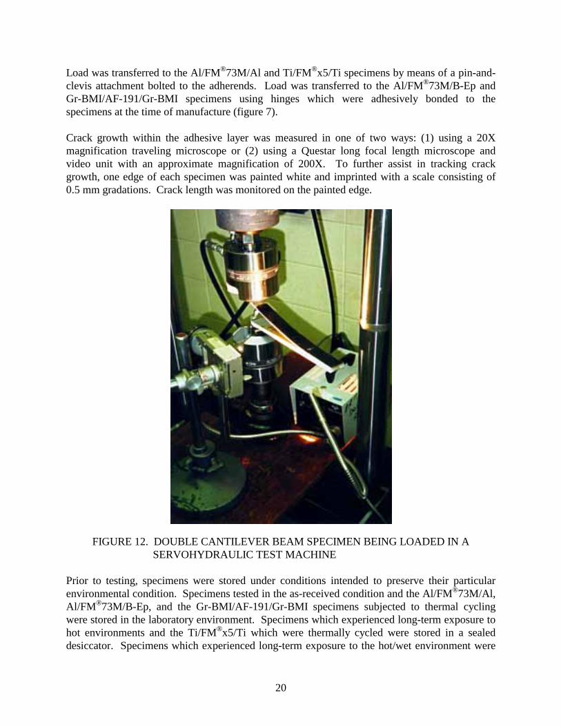
Load was transferred to the Al/FM®73M/Al and Ti/FM®x5/Ti specimens by means of a pin-and-clevis attachment bolted to the adherends. Load was transferred to the Al/FM®73M/B-Ep and Gr-BMI/AF-191/Gr-BMI specimens using hinges which were adhesively bonded to the specimens at the time of manufacture (figure 7).
Crack growth within the adhesive layer was measured in one of two ways: (1) using a 20X magnification traveling microscope or (2) using a Questar long focal length microscope and video unit with an approximate magnification of 200X. To further assist in tracking crack growth, one edge of each specimen was painted white and imprinted with a scale consisting of 0.5 mm gradations. Crack length was monitored on the painted edge.
FIGURE 12. DOUBLE CANTILEVER BEAM SPECIMEN BEING LOADED IN A SERVOHYDRAULIC TEST MACHINE
Prior to testing, specimens were stored under conditions intended to preserve their particular environmental condition. Specimens tested in the as-received condition and the Al/FM®73M/Al, Al/FM®73M/B-Ep, and the Gr-BMI/AF-191/Gr-BMI specimens subjected to thermal cycling were stored in the laboratory environment. Specimens which experienced long-term exposure to hot environments and the Ti/FM®x5/Ti which were thermally cycled were stored in a sealed desiccator. Specimens which experienced long-term exposure to the hot/wet environment were
20

21
suspended over distilled water in a sealed container and stored at 22 ±2°C (72 ±3°F) and94 ±3% rh.
3.4.1 racture Toughness (Monotonic) Testing Procedures.
Monotonic testing, using ASTM D3433-75 [35] and D5228-94a [36] as guidelines, wasconducted to obtain a fracture toughness or critical strain energy release rate (GIc). displacement rate, equal to a crack mouth opening rate, of 1.0 mm/min (0.04 in/min) was used.Deviation from linearity of a load versus displacement trace indicated the onset of crack growthin the bond line region. by optical observations. Several runs, permittingthe calculation of multiple GIc values, were performed on each specimen. Figure 13 depicts acollection of typical load versus displacement runs from a single specimen. Using the standarddeviation, sample size, and mean of these multiple values, a 95% confidence interval wascalculated for the value of GIc for each material and condition. values are shown in the figures in the results section of this report.
0
200
400
600
800
1000
1200
1400
1600
0 2 4 6 8 10 12 14 16 18 20
Displace ment, δ (mm)
Load,P (N)
Program: Lockheed Martin C-141Material: Al/FM-73M/AlSpecimen: L1D1Exposure: none, as-receivedTest Type: MonotonicTest Conditions: Lab Air, RT, 1 mm/minTest Date: 12 Apr 96Specimen Width (b): 27.127 mmAdherend Thickness (t): 9.53 mm
a = 57.60 mm
a = 115.80 mm
a = 100.39 mm
a =90.16 mm
a = 77.48 mm
a = 69.81 mm
a = 167.90 mm
a = 154.51 mma = 141.18 mm
a = 128.12 mm
observed crack growth
FIGURE 13. OAD VERSUS DISPLACEMENT DATA FROM SEVERAL RUNSPERFORMED ON A SINGLE SPECIMEN
3.4.2 atigue Testing Procedures.
Fatigue testing was carried out under displacement control using a displacement R-ratio(δmin/δmax) of 0.1. displacement control permitted applied strain energy release rateshedding so that a threshold crack growth rate could be approached as the crack propagated.
F
A crosshead
This was confirmed
Confidence intervals and mean
L
F
Using

A threshold fatigue crack growth rate of 10-6 mm/cycle (4 x 10⁻⁸ in/cycle) was chosen based upon previous work by Marceau et al. [37] and Mall et al. [38]
The Al/FM®73M/Al and Ti/FM®x5/Ti specimens were tested at a frequency of 10 Hz. Due to the flexibility of the composite adherends, large deflections (up to 10 mm (0.4 in)) were necessary to induce fatigue crack growth in the Al/FM®73M/B-Ep and Gr-BMI/AF-191/Gr-BMI specimens. Because of these large deflections, the hydraulic test system performance limited the test frequencies for these two systems to 3 Hz. For all specimens, periodic cycles conducted at 0.1 Hz captured peak and valley load and displacement values used in compliance calculations and in estimates of crack length and GI or GT.
Crack length was either optically monitored using the same procedures as employed for the monotonic fracture toughness tests or computed using compliance calculations.
Data is presented in section 5 in a manner similar to da/dN versus Δ K curves familiar to those with experience in fatigue analyses of metallic materials. However, instead of using a stress-intensity factor range (Δ K), a strain energy release rate range (Δ G) is used. This is done because the constraint caused by the relatively thick adherends on the thin bond line does not permit the formation of a fully developed plastic zone and, hence, the concept of K is invalid. The concept of G however, being based upon energy, remains useful. For the case of the DCB specimens with similar adherends, Δ K is replaced by Δ GI. Because of the lack of any residual Mode II component, Δ GI is equivalent to Δ GT, the total applied strain energy release rate range. For the case of the Al/FM®73M/B-Ep specimens with dissimilar adherends, Δ K is replaced by Δ GT
which was obtained by a combination of experimental observations and ABAQUS finite element analyses. This use of Δ GT accounts for the residual GII level in these specimens and, thus, permits the fatigue crack growth data to be easily compared to that from the other bonded systems.
4. ANAL YTICAL PROCEDURES.
Adhesively bonded joints are complex structures which may be analyzed using a variety of techniques to determine the stress states and fracture modes present at a crack tip. In many cases, for simple joint geometries and loading paths, closed-form solutions are sufficient. In other cases, a finite element model is required.
The analysis of a double cantilever beam (DCB) specimen may be carried out in closed form for specimens with identical adherends. However, for specimens with dissimilar adherends, such as the C-141 Al/FM®73M/B-Ep system, a finite element analysis was required to determine what effects thermal residual stresses, specimen curvature, and differences in the flexural modulus of the adherends had on the fracture modes present at the crack tip.
4.1 CLOSED-FORM SOLUTION FOR THE MODE I STRAIN ENERGY RELEASE RATE (GI).
The applied strain energy release rate, GI, for DCB specimens with two adherends of the same material is found using equation 1. [39, 40]
22

P2 dCGI = (1)
2b da
where P = load C = specimen compliance (δ /P) a = crack or debond length
δ = crosshead or crack mouth opening displacement b = specimen width
Using beam theory and the assumption that the DCB specimen consists of two cantilever beams with a built-in support on the end opposite the load application point, equation 1 reduces to
3PδGI = (2)
2ba
Equation 2 may be further modified [41, 42] to account for the relationship between specimen compliance and observed crack length using
3PδGI =
2b a + Δ ) (3)
(
The value Δ is the intercept of the a axis obtained from a linear relationship between C1/3 and a (figure 14). This term serves as a correction to account for the fact that the uncracked end of the DCB specimen is not completely fixed.
For the monotonic tests of the adhesives, the fracture toughnesses or critical strain energy release rates (GIc) were obtained using the modified beam theory, equation 3, the visually observed crack length, and the critical load, P, at which crack growth began. This load corresponded to the load at which the load versus displacement data deviated from linearity.
Equation 3 was also used to determine the applied strain energy release rates for fatigue tests.
Crack L
(Complia nce)1/3
Δ
Experimental Data
Crack L ength, a
C1/3
h
FIGURE 14. DETERMINATION OF THE END CORRECTION TERM, Δ
23

4.2 FINITE ELEMENT ANALYSIS.
Finite element analyses were performed on the Al/FM®73M/Al, Ti/FM®x5/Ti and, most importantly, on the Al/FM®73M/B-Ep specimens. Due to the dissimilar adherends in the Al/FM®73M/B-Ep specimens, they exhibited pronounced curvature following curing (as described previously). Thermal residual stresses, the root cause of the curvature, resulted in a thermally induced Mode II strain energy release rate (GII) at the crack tip with no applied load. Thus, the GI and GII levels could not be determined experimentally, and a finite element model was used to determine the amount of mode mixity present at the crack tip during specimen loading.
4.2.1 Programs.
Two software programs were used in this research: the commercially available ABAQUS and GAMNAS (Geometric and Material Nonlinear Analysis for Structures) developed at NASA-Langley. [43, 44] ABAQUS, which was used for the majority of the finite element studies is a versatile commercial code with extensive analytical capabilities including thermal residual stress calculations. GAMNAS, developed specifically for bonded joints, cannot analyze thermal residual stresses. It was used to verify ABAQUS analyses of specimens with identical adherends which did not contain thermal residual stresses. Both programs can conduct material and geometric nonlinear analyses. Only geometric nonlinearities, do to the significant nodal rotations at the crack tip caused by the curvature of the Al /FM®73M/B-Ep specimens, were accounted for in this research. Materials were assumed to be linearly elastic (this will be discussed in the following section).
4.2.2 Assumptions and Model Details.
In the analytical effort, all materials were assumed to be linearly elastic. This assumption was made for several reasons. Room temperature shear data exists for the FM®73 and AF-191 adhesives but not for the FM®x5 adhesive. In addition, the limited data available is primarily for room temperature behavior. The lack of stress-strain curves for the selected adhesives forced the assumption of linear elasticity and prevented the consideration of temperature dependence.
Because of the large width of the specimens compared to the bond line thickness, plane-strain was also assumed.
Models were developed for each specimen geometry. These models were two-dimensional and could be used by both the ABAQUS and GAMNAS programs. Four-noded quadrilateral elements were used. To enhance the performance of these elements under bending conditions, a reduced integration technique was used. Typically, the adhesive layer was modeled using four rows of elements and the adherends were modeled with ten rows for monolithic metal adherends or with one row per ply in the case of composite adherends.
24

4.2.3 Determination of Strain Energy Release Rate.
Strain energy release rates were calculated by the finite element programs using a modified crack closure technique. [45] This technique determines the nodal forces and displacements required to close the crack to its original position. Figure 15 shows this technique schematically. The crack tip within a component subject to an opening force, P, is identified by two nodes, A and B. These nodes originally share the same location before crack propagation (figure 15b). As the crack extends under Mode I loading, these two nodes are released and separated by a distance δ y
(figure 15a). The crack closure technique computes this separation distance and the nodal force, pn, required to return nodes A and B to their original position. A very stiff spring element located between nodes C and D is used to calculate this force, pn. The nodal force multiplied by the nodal displacement is the work or energy required to close the crack tip. This quantity is equivalent to the strain energy released as the crack tip propagates from nodes AB to nodes CD. The strain energy, δ ypn, divided by the amount of new crack area which is formed as the crack propagates, 2Δ a, is the Mode I strain energy release rate or GI. Similar steps are used to separate nodes A and B in the x direction under to Mode II loading to calculate GII. Due to bond line rotation, forces and displacements are transformed to a coordinate system with axes that are parallel and perpendicular to the crack.
P
pn
pn
A
P
P
C
Crack Propagates
Δ a
B D B
A δ y
C
D
Crack Closes
Δ aP
(a) (b)
FIGURE 15. THE MODIFIED CRACK CLOSURE TECHNIQUE (MODEL IS OF UNIT WIDTH)
Critical strain energy release rate (GIc) values were obtained by applying the experimentally observed critical load at the onset of crack growth to the finite element model. The finite element program then computed a displacement and, in turn, a strain energy release rate which, because the critical load was used, was equal to GIc.
25
4.2.4 Verification of Analysis.
Before analyzing the curved Al/FM®73M/B-Ep specimens, the results of the analyses of Al/FM®73M/Al and Ti/FM®x5/Ti specimens were verified. These systems were fabricated using a single material for both adherends and, therefore, the results of the ABAQUS and GAMNAS programs could be directly compared with those obtained from the closed-form solution method described in section 4.1.
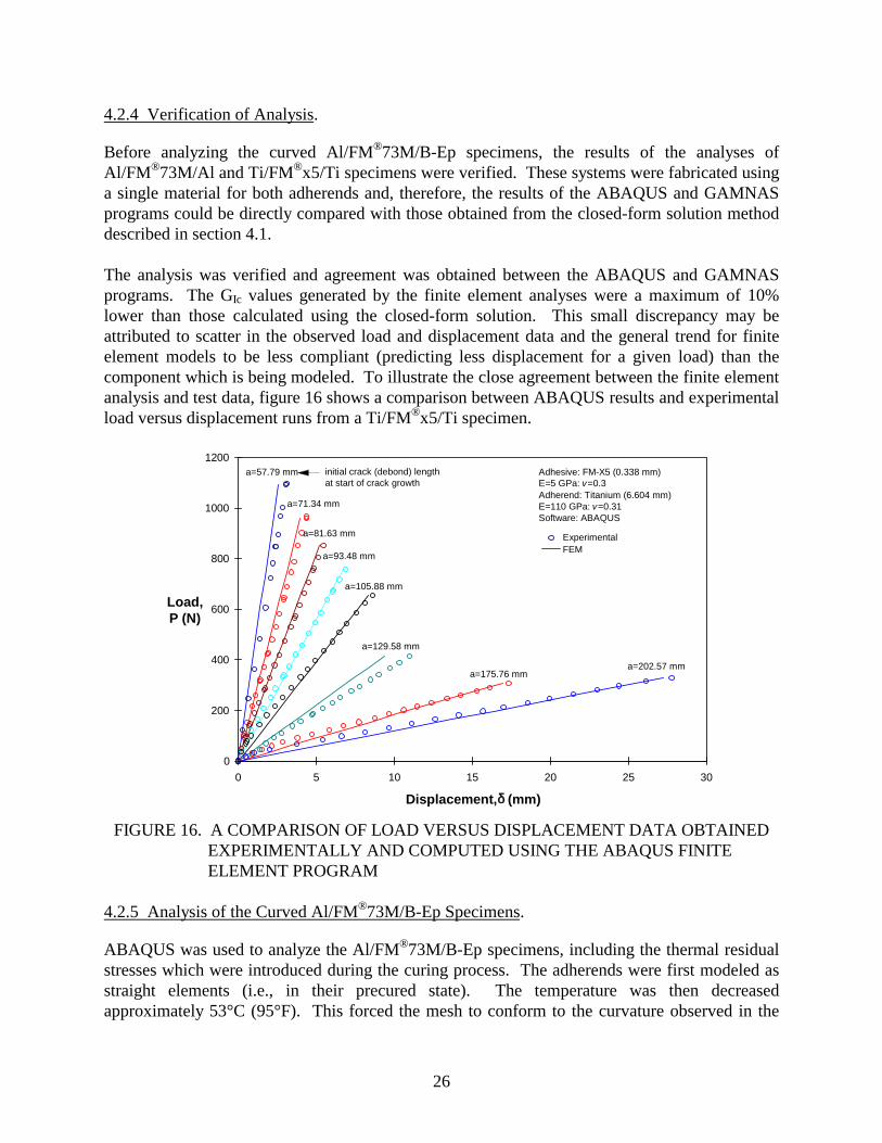
The analysis was verified and agreement was obtained between the ABAQUS and GAMNAS programs. The GIc values generated by the finite element analyses were a maximum of 10% lower than those calculated using the closed-form solution. This small discrepancy may be attributed to scatter in the observed load and displacement data and the general trend for finite element models to be less compliant (predicting less displacement for a given load) than the component which is being modeled. To illustrate the close agreement between the finite element analysis and test data, figure 16 shows a comparison between ABAQUS results and experimental load versus displacement runs from a Ti/FM®x5/Ti specimen.
1200
1000
800
Load, 600
P (N)
400
200
0
0 5 10 15 20 25 30
Experimental FEM
a=57.79 mm
a=71.34 mm
a=81.63 mm
a=93.48 mm
a=105.88 mm
a=129.58 mm
a=175.76 mm a=202.57 mm
Adhesive: FM-X5 (0.338 mm) E=5 GPa: v =0.3 Adherend: Titanium (6.604 mm) E=110 GPa: v =0.31 Software: ABAQUS
initial crack (debond) length at start of crack growth
Disp lacemen t,δ (mm)
FIGURE 16. A COMPARISON OF LOAD VERSUS DISPLACEMENT DATA OBTAINED EXPERIMENTALLY AND COMPUTED USING THE ABAQUS FINITE ELEMENT PROGRAM
4.2.5 Analysis of the Curved Al/FM®73M/B-Ep Specimens.
ABAQUS was used to analyze the Al/FM®73M/B-Ep specimens, including the thermal residual stresses which were introduced during the curing process. The adherends were first modeled as straight elements (i.e., in their precured state). The temperature was then decreased approximately 53°C (95°F). This forced the mesh to conform to the curvature observed in the
26

specimens. As explained in section 4.2.2, room temperature material properties were used for the model due to a lack of information on their temperature dependence. The room temperature properties caused the “effective” change in temperature required for the model (≈ 53°C (95°F)) to be less than the actual change in temperature experienced by the specimens during cool down (≈ 95°C (170°F)). This temperature difference is suspected to be caused by relaxation which occurs during cool down and results in a lower effective cure temperature. Thus, it is recognized that use of temperature invariant properties for the adhesive is a simplification. The crack was placed at the interface between the adhesive and the boron-epoxy adherend. The choice of this crack location was based on the observation that fracture in the Al/FM®73M/B-Ep system appeared to occur in the matrix of the composite very near to the adhesive/composite interface.
5. RESULTS AND DISCUSSION.
5.1 ENVIRONMENTALLY INDUCED PHYSICAL CHANGES.
Moisture absorption or desorption was experienced by all specimens subjected to long-term isothermal exposure. These changes are shown graphically in figure 17. Because elevated temperatures and low humidity reduced the amount of ambient moisture in the bond line, specimens exposed to hot environments lost weight during exposure. In contrast, elevated temperatures and high humidity forced the bond line to absorb water thereby causing specimens exposed to hot/wet environments to gain weight due to moisturization. Al/FM®73M/B-Ep specimens exposed to the hot/wet environment experienced greater weight gains than the Al/FM®73M/Al specimens because of the greater amount of moisture absorbed by the boron-epoxy adherends. Bond line saturation for the Al/FM®73M/Al and Al/FM®73M/B-Ep was estimated to occur in approximately 200 hours based upon a leveling off of the weight change curve for the Al/FM®73M/Al specimens.
Visual observations of the specimens during long-term exposure or thermal cycling revealed few noticeable changes. Corrosion products formed on the aluminum surfaces of the Al/FM®73M/Al and Al/FM®73M/B-Ep specimens exposed to the hot/wet environment. The exposed edges of the AF-191 adhesive bond line in the F-22 specimens changed color from a pale yellow to a dark brown during approximately 3000 hours of exposure to 104°C (220°F). Neither the exposed HSCT Ti/FM®x5/Ti specimens nor any of the thermally cycled specimens exhibited any observable changes in appearance.
27

28
-0.25
0.00
0.25
0.50
0.75
0 1000 2000 3000 4000 5000
C-141
C-141
F-22
HSCT
HSCT
-0.25
0.00
0.25
0.50
0.75
WeightChange
(%)
Hours
FIGURE 17. EIGHT CHANGES OF SPECIMENS SUBJECTED TO LONG-TERMISOTHERMAL EXPOSURE
5.2 M®73M/Al.
The Al/FM®73M/Al specimens were fabricated from materials used on the C-141 transportaircraft and also in the USAF’s PABST study. [4] One group of specimens was tested in the as-received state with no pretest environmental exposure. roup was subjected to 5,000hours of hot/wet isothermal exposure at 71°C (160°F) and 94±3% rh prior to mechanical testing.A third group was subjected to 320 hours of hot/wet isothermal exposure at 71°C (160°F) and94±3% rh, followed by 100 thermal cycles between -54°C (-65°F) and 71°C (160°F) prior tomechanical testing.
5.2.1 racture Toughness.
Monotonic Mode I testing of the Al/FM®73M/Al system revealed a strong dependence of thefracture toughness (GIc) on environmental exposure. ved toughness wasapproximately 2800 J/m2 (16 in·lb/in2). lue is in agreement with GIc values obtained forFM®73M by Ting and Cottington [46] and Ripling, et al. [47] As shown in figure 18, thermalcycling reduced GIc by approximately 30%, and 5000 hours of exposure to a hot/wet environmentreduced GIc by approximately 70% as compared to the fracture toughness of the as-receivedmaterial. Because of the nonoverlapping confidence intervals, these changes are statisticallysignificant.
(71°C [160°F]/>90%rh)Al/FM-73/Al
(71°C [160°F]/>90%rh)Al/FM-73/B-Ep
(104°C [220°F])Gr-BMI/AF-191/Gr-BMI
(177°C [350°F])Ti/FM-X5/Ti
(71°C [160°F]/>90% rh)Ti/FM-X5/Ti
W
Al/F
A second g
F
The as-receiThis va

4000
3500
3000
2500
GIC 2000
(J/m2)
1500
1000
500
0
As Received 2798 J/m 2
(16.0 in·lb/in 2) 27 values
Cycled 1978 J/m 2
(11.3 in·lb/in 2) 6 values
Exposed 860 J/m 2
(4.9 in·lb/in2) 10 values
Expos ure: 5,000 hrs @ 71°C (160°F)/>90% rh Cycling : 100 cycles, -54°C (-65°F) to 71°C (160°F)
after 320 hrs @ 71°C (160°F)/>90% rh
Bars indicate ± 95% Confidence Interval
FIGURE 18. MODE I FRACTURE TOUGHNESS OF THE Al/FM®73M/Al BONDED SYSTEM
5.2.2 Crack Path and Fracture Surfaces.
Crack progression in these specimens was cohesive. The crack propagated through the middle of the adhesive layer, relatively distant from either adhesive-adherend interface, leaving an adhesive layer on both adherends (figure 19). Fracture surfaces showed evidence of some distributed porosity within the bond line consisting mainly of pores with diameters of 1.5 mm (0.06 in) of less. During testing, scrim cloth fibers bridged the open crack mouth for approximately 5 mm (0.20 in) behind the crack tip. The shape of the crack front was slightly curved with the interior advancing 1-2 mm (0.04-0.08 in) ahead of the edges.
No significant differences were noted among the fracture surfaces of the specimens exposed to the various environments. Although some discoloration was seen around the edges of interior voids, the fracture path was always cohesive. This suggests that the surface preparation for the aluminum was adequate for the environmental conditions examined.
FIGURE 19. FRACTURE SURFACES OF THE Al/FM®73M/Al BONDED SYSTEM (AS RECEIVED)
29
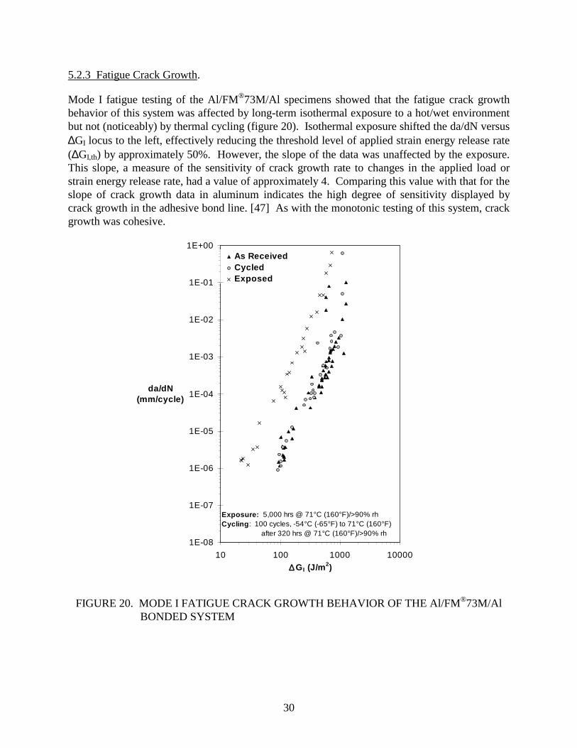
5.2.3 Fatigue Crack Growth.
Mode I fatigue testing of the Al/FM®73M/Al specimens showed that the fatigue crack growth behavior of this system was affected by long-term isothermal exposure to a hot/wet environment but not (noticeably) by thermal cycling (figure 20). Isothermal exposure shifted the da/dN versus Δ GI locus to the left, effectively reducing the threshold level of applied strain energy release rate (Δ GI,th) by approximately 50%. However, the slope of the data was unaffected by the exposure. This slope, a measure of the sensitivity of crack growth rate to changes in the applied load or strain energy release rate, had a value of approximately 4. Comparing this value with that for the slope of crack growth data in aluminum indicates the high degree of sensitivity displayed by crack growth in the adhesive bond line. [47] As with the monotonic testing of this system, crack growth was cohesive.
1E+00
1E-01
1E-02
1E-03
da/dN 1E-04(mm/cycl e)
1E-05
1E-06
1E-07
1E-08
As Received Cycl ed Expos ed
Exposure: 5,000 hrs @ 71°C (160°F)/>90% rh Cycling : 100 cycles, -54°C (-65°F) to 71°C (160°F)
after 320 hrs @ 71°C (160°F)/>90% rh
10 100 1000 10000
Δ GI (J /m2)
FIGURE 20. MODE I FATIGUE CRACK GROWTH BEHAVI OR OF THE Al/FM®73M/Al BONDED SYSTEM
30

5.3 Al/FM®73M/B-Ep.
These specimens were fabricated from materials used for repairs to aircraft such as the C-141 transport. One group of specimens was tested in the as-received state with no pretest environmental exposure. A second group was subjected to 5,000 hours of hot/wet isothermal exposure at 71°C (160°F) and 94 ±3% rh prior to mechanical testing. A third group was subjected to 320 hours of hot/wet isothermal exposure at 71°C (160°F) and 94 ±3% rh followed by 100 thermal cycles between -54°C (-65°F) and 71°C (160°F) prior to mechanical testing.
5.3.1 Finite Element Analysis of the Al/FM®73M/B-Ep System.
Due to the curvature of these specimens, an ABAQUS finite element analysis (as described in section 4.2) was used to determine the postcure residual stress state in the bond line. The residual stress state was calculated to contain a compressive normal peel component (perpendicular to the bond line) of approximately 4 MPa (0.58 ksi) and a shear component (parallel to the bond line) of approximately 37 MPa (5.37 ksi). The stress state can be translated into a residual applied strain energy release rate in Mode II (GII) of approximately 90 J/m2 (0.51 in·lb/in2) present in the specimens following cure and prior to testing. The adherends are forced together due to the compressive residual normal stresses and, therefore, an initial residual GI
component is absent.
During testing, the state of the applied strain energy release rate changed as load was increased. Figure 21 shows this trend for a specimen with a given crack length. (Each crack length encountered during testing required a separate set of curves similar to those shown in figure 21.) In this figure, the residual GII is evident at zero load. The total strain energy release rate is simply the sum of GI and GII. Calculations accounted for the adhesive nature of the crack path (see section 5.3.3).
ABAQUS analyses were used to determine the relationships between GI, GII, GT, and applied load for a series of crack lengths resulting in a series of plots similar to that shown in figure 21. Using this series of plots, GI, GII, and GT values were determined for the various combinations of loads and crack lengths encountered during monotonic fracture toughness and fatigue testing. Not every crack length was modeled using ABAQUS. The strain energy release rates for crack lengths which were not modeled were obtained through interpolation.
31

800
700
600
500
G 400
(J / m2)
300
200
100
0 0 50 100 150 200 250
Lap: Br-Ep=2.74 mm Strap: Al=9.53 mm
Debond length = 78.65 mm
GTotal
GI
GII
Adhesive thickness 0.225 mm Cohesive failure was at middle of adhesive Adhesive failure was at adhesive boron interface Thermal mismatch included (Δ T = 95° F) Software used: US ABAQ
Applie d Loa d (N)
FIGURE 21. COMPUTED MODE I, MODE II, AND TOTAL APPLIED STRAIN ENERGY RELEASE RATES FOR AN Al/FM®73M/B-Ep SPECIMEN AS A FUNCTION OF LOAD FOR A SINGLE CRACK LENGTH
5.3.2 Fracture Toughness.
The fracture toughness of the Al/FM®73M/B-Ep system was significantly less than that of the Al/FM®73M/Al system. Note that the fracture toughness of the Al/FM®73M/B-Ep system is expressed in terms of GT to reflect the presence of GI and GII, whereas the fracture toughness of the Al/FM®73M/Al system is express in terms of GI which is equivalent in the case of similar adherends to GT. The as-received fracture toughness of the Al/FM®73M/B-Ep system was approximately 840 J/m2 (4.8 in·lb/in2). As with the Al/FM®73M/Al system, the thermally cycled and isothermally exposed specimens revealed significant losses in fracture toughness. Figure 22 displays these trends and identifies the amount of the fracture toughness attributed to Modes I and II.
32

2000
1500
GTC 1000
(J/m2)
500
0
As Received
838 J/m 2
(4.8 in·lb/in2) 7 values
Cycled
455 J/m 2
(2.6 in·lb/in2) 5 values
Exposed
402 J/m2 (2.3 in·lb/in 2)
5 values
Exposure: 5,000 hrs @ 71°C (160°F)/>90% rh Cycling : 100 cycles, -54°C (-65°F) to 71°C (160°F)
after 320 hrs @ 71°C (160°F)/>90% rh
Bars indicate ± 95% Confidence Interval
GT
GI
GII
FIGURE 22. FRACTURE TOUGHNESS OF THE Al/FM®73M/B-Ep BONDED SYSTEM
5.3.3 Crack Path and Fracture Surfaces.
Crack growth in the Al/FM®73M/B-Ep specimens appeared to take place in the matrix of the composite adherend very near to the adhesive/composite interface. This was determined by visual and microscopic observations of the fracture surfaces. No differences were noticed among the specimens exposed to various environments. The nature of the crack path is evident in figure 23 which shows that the black boron-epoxy adherend is nearly devoid of the lighter (yellowish) FM®73M adhesive. Some fiber bridging occurred and can be seen from the few fibers (dark lines) which appear on the lower (aluminum) adherend in figure 23. The path of the crack through the relatively brittle matrix material rather than through the tougher epoxy adhesive explains the much lower fracture toughness values for the Al/FM®73M/B-Ep systems as compared to the Al/FM®73M/Al system.
FIGURE 23. FRACTURE SURFACES OF THE Al/FM®73M/Al BONDED SYSTEM (AS RECEIVED)
33

5.3.4 Fatigue Crack Growth.
As determined by a best fit through the data, the correlation between da/dN and Δ GT was better than the correlation between da/dN with Δ GI or Δ GII. The da/dN data are plotted against Δ GT in figure 24. The correlation of da/dN with Δ GT provides a direct comparison between the fatigue behavior of the Al/FM®73M/B-Ep system and the other bonded systems investigated since, for the latter systems, fatigue data was plotted with respect to Δ GI which was equivalent to Δ GT.
1E+00
1E-01
1E-02
1E-03
da/dN 1E-04
(mm/cyc le)
1E-05
1E-06
1E-07
1E-08 10 100 1000 10000
As Received Cycled Exp osed
Expos ure: 5,000 hrs @ 71°C (160°F)/>90% rh Cyclin g : cycles, -54°C (-65°F) to 71°C (160°F)
after 320 hrs @ 71°C (160°F)/>90% rh Based Upon FEM Results
100
ΔGT (J/m 2)
FIGURE 24. FATIGUE CRACK GROWTH BEHAVI OR OF THE Al/FM®73M/B-Ep BONDED SYSTEM
Comparison of the fatigue data from the Al/FM®73M/Al and Al/FM®73M/B-Ep systems shows that the slope of the Al/FM®73M/B-Ep data system is greater (≈ 8-12). This suggests an even greater sensitivity of crack growth rate to applied G values and is consistent with the lower fracture toughness of the Al/FM®73M/B-Ep system.
5.4 Gr-BMI/AF-191/Gr-BMI.
The Gr-BMI/AF-191/Gr-BMI specimens were fabricated from materials to be used on the F-22 fighter aircraft. One group of specimens was tested in the as-received state with no pretest environmental exposure. A second group was subjected to 5,000 hours of hot isothermal exposure at 104°C (220°F) and 0% rh prior to mechanical testing. A third group was subjected
34

to 320 hours of hot/wet isothermal exposure at 71°C (160°F) and 94±3% rh followed by 100 thermal cycles between -54°C (-65°F) and 104°C (220°F) prior to mechanical testing.
5.4.1 Fracture Toughness.
The Mode I fracture toughnesses of the Gr-BMI/AF-191/Gr-BMI specimens subjected to various environments are shown in figure 25. Although the mean values for the as-received and thermally cycled conditions differ slightly, no significant distinction can be made between the two conditions because of overlapping confidence intervals. However, the degradation caused by long-term exposure to 104°C (220°F) does appear to be significant. The lay-up of the adherends did not appear to affect the calculated Mode I fracture toughness of this bonded system.
4000
3500
3000
GIC 2500
(J/m 2) 2000
1500
1000
500
0 Quasi-Isotropic Adherends
As Received 1721 J/m 2
(9.8 in·lb/in 2) 19 values
As Received 1595 J/m
2
(9.1 in·lb/in 2) 9 values
Cycl ed 1631 J/m 2
(9.3 in·lb/in 2)
9 values
Cycl ed 1620 J/m 2
(9.3 in·lb/in 2 ) 7 values
Exposed 1235 J/m 2
(7.1 in·lb/in 2 ) 7 values
Unidirectional Adherends
Exposure: 5,000 hrs @ 104°C (220°F) Cycl ing : 100 cycles, -54°C (-65°F) to 104°C (220°F)
after 320 hrs @ 71°C (160°F)/>90% rh
Bars indicate ± 95% Confidence Interval
[04,90*] s [±45,0 2,±45,90] s
FIGURE 25. MODE I FRACTURE TOUGHNESS OF THE Gr-BMI/AF-191/Gr-BMI BONDED SYSTEMS
5.4.2 Crack Path and Fracture Surfaces.
The crack path for the Gr-BMI/AF-191/Gr-BMI was, in general, cohesive. However, because the scrim cloth within the AF-191 was located closer to one face of the adhesive film, the crack path was offset towards one adherend and followed the plane of the scrim cloth. The crack front was nearly straight across the adherends with little evidence of tunneling in which the interior portion of the crack grows more rapidly than that located near the edge. In specimens containing quasi-isotropic adherends, the crack often departed from the adhesive layer and caused interlaminar cracking within the ± 45° plies. These plies were located at the bond line, and their cracking indicates the importance of placing a 0° ply at the adhesive-adherend interface to prevent cracks from growing into composite adherends (figure 26). No significant differences were noted between the specimens which were tested in the as-received state and those tested following
35

environmental exposure. However, some slight darkening of the AF-191 adhesive was observed on the exposed edges of the specimens which were subjected to long-term isothermal exposure.
FIGURE 26. FRACTURE SURFACES OF THE Gr-BMI/AF-191/Gr-BMI BONDED SYSTEMS (AS RECEIVED), UPPER PHOTO: UNIDIRECTIONAL ADHEREND, LOWER PHOTO: QUASI-ISOTROPIC ADHEREND
5.4.3 Fatigue Crack Growth.
Limited fatigue data from the Gr-BMI/AF-191/Gr-BMI system suggest a trend exhibited by the Al/FM®73M/Al and Al/FM®73M/B-Ep systems: no discernible difference in crack growth behavior between the as-received and thermally cycled specimens (figure 27). In addition, the effect of isothermal exposure to a high temperature also appears to be negligible. Threshold crack growth appears to begin at an applied Δ GI level of approximately 100 J/m2 (0.57 in·lb/in2). The slope of the crack growth data is approximately 6, again indicating a relatively high degree of sensitivity to small changes in the applied load or strain energy release rate. Cracking was cohesive and exhibited the same characteristics as described for the monotonic tests.
As of the writing of this report, no exposed specimens or quasi-isotropic specimens have been tested in fatigue.
36

1E+00
1E-01
1E-02
1E-03
da/dN (mm/cycle) 1E-04
1E-05
1E-06
1E-07
1E-08
10 100 1000 10000
As Receiv ed Cycled Exposed
Exposu re: 5,000 hrs @ 104°C (20°F), 0% rh
Cycling: 100 cycles, -54°C (-65°F) to 104°C (220°F) after 300 hrs @ 71°C (160°F), >90% rh
Δ Gl (J/m2)
FIGURE 27. MODE I FATIGUE CRACK GROWTH BEHAVI OR OF THE UNIDIRECTIONAL Gr-BMI/AF-191/Gr-BMI BONDED SYSTEM
5.5 Ti/FM®x5/Ti.
The Ti/FM®x5/Ti specimens were fabricated from materials to be used on the future HSCT aerospace vehicle. One group of specimens was tested in the as-received state with no pretest environmental exposure. A second group was subjected to 5,000 hours of hot isothermal exposure at 177°C (350°F) and 0% rh prior to mechanical testing. A third group was subjected to 5,000 hours of hot/wet isothermal exposure at 71°C (160°F) and 94±3% rh prior to mechanical testing. A fourth group was subjected to 500 thermal cycles between -54°C (-65°F) and 163°C (325°F) prior to mechanical testing.
5.5.1 Fracture Toughness.
Figure 28 shows the results of the monotonic fracture toughness tests on the Ti/FM®x5/Ti system. Differences in the mean values among the specimens exposed to various conditions do
37

not suggest significant differences in the GIc values because of overlapping confidence intervals. Therefore, it appears that the Ti/FM®x5/Ti system is relatively insensitive to environmental exposure and displays a fracture toughness of 2000-2500 J/m2 (11.5-14.3 in·lb/in2). This is in agreement with values obtained by Parvatareddy, et al. [48] (~2000-2400 J/m2
[~11.4-13.7 in·lb/in2]).
4000
3500
3000
2500
As Received 2514 J/m2
(14.4 in·lb/in2) 18 values
Cycled 2275 J/m2
(13.0 in·lb/in2) 6 values
Exposed hot /wet 2418 J/m2
(13.8 in·lb/in2) 10 values
Expos ed hot
1915 J/m2
(10.9 in·lb/in2) 9 values
Expos ure: hot - 5,000 hrs @ 177°C (350°F) hot/wet - 5,000 hrs @ 71C (160°F)/>90% rh
Cycling : 500 cycles, -54°C (-65°F) to 163°C (325°F)
Bars indicate ±95% Confidence Interval
GIC
(J/m 2) 2000
1500
1000
500
0
FIGURE 28. FRACTURE TOUGHNESS OF THE Ti/FM®x5/Ti BONDED SYSTEM
5.5.2 Crack Path and Fracture Surfaces.
Crack growth was generally cohesive in this system. The crack propagated mainly along the plane of the scrim cloth (figure 29). However, the fracture surfaces of the specimen subjected to long-term isothermal exposure at 177°C (350°F) exhibited a greater degree of cracking in resin-rich regions between the scrim cloth and adherends suggesting a possible change in the properties of the polyimide material. The shape of the crack front was indistinct on the fracture surfaces perhaps due to the presence of the relatively bulky scrim cloth.
FIGURE 29. FRACTURE SURFACES OF THE Ti/FM®x5/Ti BONDED SYSTEM (AS RECEIVED)
38
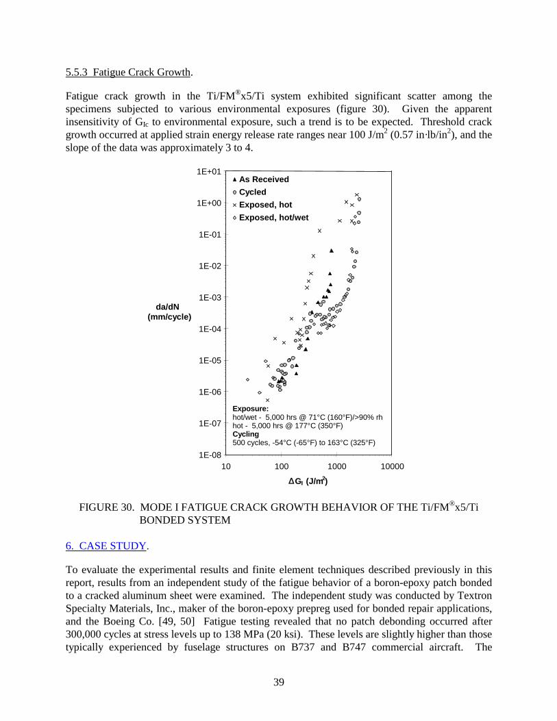
5.5.3 Fatigue Crack Growth.
Fatigue crack growth in the Ti/FM®x5/Ti system exhibited significant scatter among the specimens subjected to various environmental exposures (figure 30). Given the apparent insensitivity of GIc to environmental exposure, such a trend is to be expected. Threshold crack growth occurred at applied strain energy release rate ranges near 100 J/m2 (0.57 in·lb/in2), and the slope of the data was approximately 3 to 4.
1E+01
1E+00
1E-01
1E-02
1E-03 da/dN
(mm/cycle) 1E-04
1E-05
1E-06
1E-07
1E-08 10 100 1000 10000
As Received
Cycled
Exposed , hot
Exposed , hot /wet
Expos ure: hot/wet - 5,000 hrs @ 71°C (160°F)/>90% rh hot - 5,000 hrs @ 177°C (350°F) Cycling: 500 cycles, -54°C (-65°F) to 163°C (325°F)
Δ GI (J/m2)
FIGURE 30. MODE I FATIGUE CRACK GROWTH BEHAVI OR OF THE Ti/FM®x5/Ti BONDED SYSTEM
6. CASE STUDY.
To evaluate the experimental results and finite element techniques described previously in this report, results from an independent study of the fatigue behavior of a boron-epoxy patch bonded to a cracked aluminum sheet were examined. The independent study was conducted by Textron Specialty Materials, Inc., maker of the boron-epoxy prepreg used for bonded repair applications, and the Boeing Co. [49, 50] Fatigue testing revealed that no patch debonding occurred after 300,000 cycles at stress levels up to 138 MPa (20 ksi). These levels are slightly higher than those typically experienced by fuselage structures on B737 and B747 commercial aircraft. The
39

Textron/Boeing specimens were analyzed using the ABAQUS finite element program to determine the level of strain energy release rate applied during the fatigue testing. The results of the finite element analysis were then compared to the experimental data described previously. The intent of this analysis and comparison was to determine whether the results of the Textron/Boeing study were to be expected given the analytical and experimental results discussed earlier in this report.
6.1 THE TEXTRON/BOEING PROJECT.
Fatigue test specimens were fabricated from 7075-T6 aluminum, F4/5521 boron-epoxy prepreg, and FM®73M adhesive. [15] Aluminum panels contained a 13-mm (0.5-in) -long saw cut simulating a crack to be patched by a six-ply, unidirectional boron-epoxy doubler. The doubler and adhesive were cocured onto the aluminum sheet. Because of the difference in coefficients of thermal expansion between the aluminum and boron-epoxy, specimens contained a residual curvature prior to testing. The cross-sectional stiffness ratio between the doubler and the aluminum was 1.4:1. A 25:1 ply drop-off ratio (taper) was used at the edges of the doubler. Several boron-epoxy doubler geometries were investigated. Figure 31 shows a schematic of a typical fatigue test specimen.
Aluminum
Boron-Epoxy
Region Used for Finite
Element Model
FIGURE 31. THE TEXTRON/BOEING FATIGUE TEST SPECIMEN
Fatigue tests were conducted at constant amplitude at 5 Hz, R=0.15, and stress levels of 21 to 138 MPa (3 to 20 ksi). Run out was set at 300,000 cycles. The lower stress level was chosen to eliminate the curvature of the specimens caused by the difference in the coeffic ients of thermal expansion. The upper stress limit corresponded to the sum of the maximum stress level experienced by commercial aircraft fuselage skins (≈ 117 MPa (17 ksi)) and the 21 MPa (3 ksi) offset required to eliminate specimen curvature. Testing was conducted using grips which were rigidly mounted to the test frame (i.e., fixed grips).
40

6.2 FINITE ELEMENT MODEL.
The Textron/Boeing test specimen was simplified and analyzed as a two-dimensional, plane-strain model using the ABAQUS software. Since the patch was symmetric about the vertical axis, only half of the patch was modeled. A sketch of the model is shown below (figure 32). The model contains 3827 nodes and 3560 incompatible modes, 4-node quadrilateral elements designed specifically to accommodate bending. The aluminum and the adhesive were modeled using eight and four layers of elements, respectively. Each boron-epoxy ply was modeled by a single layer of elements. Room temperature material properties were used and were assumed to be in the linearly elastic regime and temperature invariant (table 4).
Crack 0.762
145 98
3.81
FM®73M Adhesive
7075-T6 Aluminum
Boron-Epoxy
1-mm Bond Line
1.6
- All measurements in mm - Boron-epoxy ply thickness: 0.127 mm - Adhesive thickness: 0.127 mm
FIGURE 32. MODEL OF THE TEXTRON/BOEING FATIGUE TEST SPECIMEN
TABLE 4. MATERIAL PROPERTIES USED FOR THE MODEL OF THE TEXTRON/BOEING SPECIMEN
Material E11
(GPa) E22
(GPa) E33
(GPa) v12
α 12
(x 106/°F) α 23
(x 106/°F) α 13
(x 106/°F) 7075-T6
Aluminum 70.8 70.8 70.8 0.33 13 13 13
FM®73M 2.07 2.07 2.07 0.34 40 40 40
Boron-Epoxy 207 17.2 17.2 0.21 2.5 13.1 13.1
The Textron/Boeing study investigated debonds at the tip of the crack in the aluminum panel but did not address a crack at the edge of the doubler. In the present modeling effort at Georgia Institute of Technology, a 1-mm (0.04-in) crack was introduced at the midplane of the adhesive at the doubler tip. This flaw size was chosen to simulate a defect which is undetectable using current non-destructive inspection techniques. The size was also based upon void sizes observed in Al/FM®73M/Al double cantilever beam specimens. Finally, the use of a bond line defect also provided a location at which to calculate a strain energy release rate.
41

After decreasing the temperature to model the residual curvature due to residual stress in the test specimens, [17] the finite element model was loaded in a series of steps simulating test conditions (figure 33).
- temperature drop applied - result: slight specimen curvature - specimen schematic:
“F lexible Gr ip” Condition
load
- mechanical load (stress) applied - right end not constrained to fit
into gripping system - specimen schematic:
“F ixed Gr ip” Condition couple
- couple applied - right end constrained to fit into gripping system
- specimen schematic:
load
- mechanical load (stress) applied - specimen schematic:
FIGURE 33. GRIP CONDITIONS USED IN MODELING THE TEXTRON/BOEING EXPERIMENTS
For the cool down step (step 1), the left end of the specimen was restrained in the horizontal direction, the left corner was pinned, and the right end was left free. This set of boundary conditions was based upon specimen symmetry and represents the constraints on the specimens during fabrication. A 14° C (25° F) temperature drop permitted the elimination of the induced specimen curvature with the application of a 21 MPa (3 ksi) stress (as observed during the Boeing/Textron experiments). [17]
The temperature drop used in the finite element analysis was less than that experienced by the specimens during the postcure cool down from the cure temperature to the test temperature (Δ T ~ 61° C (110° F)). Possible reasons for this discrepancy are the assumption of temperature invariant properties and the fact that the boron-epoxy and the adhesive were cocured. During cool down in cocuring, residual stresses in the adhesive layer may not begin to form until the bonded assembly reaches a temperature considerably below the curing temperature. Thus, the
42

difference between the cure temperature and the test temperature may be less than the difference between the temperature at which residual stresses begin to develop and the test temperature. The temperature drop employed by the model reflects this possible phenomenon because it is less than the difference between the cure temperature and the test temperature. Regardless of the reason for such a difference in the experimentally observed and modeled temperature drops, the finite element model accurately simulated the curvature of the specimens prior to testing and satisfied the criteria that the specimen curvature was eliminated with the application of a 21-MPa (3-ksi) stress during testing.
For fixed-grip conditions, the right end of the specimen could not be curved because any curvature would prevent it from being able to fit into a fixed grip. Physically, forces and moments were applied to the curved Boeing/Textron specimens to enable them to fit into the fixed grips used in testing. This situation was simulated in the finite element model by applying a couple (concentrated moment) to the right end of the specimen following the temperature drop and prior to the application of the mechanical load. This couple returned the rightmost specimen edge to a vertical alignment and forced the right end of the specimen into a configuration that could fit into a typical fixed grip prior to loading.
As shown in figure 33, the boundary conditions used during the application of the couple were identical to those used in modeling the temperature drop. Upon the application of the mechanical test load, the boundary conditions were changed to simulate the conditions imposed upon the specimen by the test machine.
The strain energy release rate was calculated using the modified crack closure method described previously.
The analysis accounted for the geometric nonlinearity introduced by large rotations due to the asymmetry of the specimen.
6.3 RESULTS AND DISCUSSION.
After simulating the temperature drop to induce curvature, a load was applied to the right end of the model using an attributed area method to prevent the creation of a bending moment. Mode I, Mode II, and total strain energy release rates (figure 34) were calculated using the ABAQUS program.
Figure 34 shows that Mode II dominated the response of the specimen under applied stress, comprising the majority of the total applied strain energy release rate (GT). At zero applied stress, the thermal residual stresses which caused specimen curvature also induced a GII level less than 1 J/m2 (5.71 x 10⁻³ in·lb/in2). In general, the induced GII increased with increasing applied stress, and the strain energy release rate at the minimum fatigue stress of 21 MPa (3 ksi) was negligible.
43

60
50
40
G 30
(J / m2)
20
10
0
0 20 40 60 80 100 120 140 160
GI
GII
GT
GT and GII
Appli ed Stress (MPa)
FIGURE 34. STRAIN ENERGY RELEASE RATES PRODUCED BY STRESSES APPLIED TO THE TEXTRON/BOEING SPECIMEN
During the fatigue tests done by Textron and Boeing, the Mode I strain energy release rate (GI) varied between zero and approximately 8 J/m2 (4.6 x 10⁻² in·lb/in2) and the Mode II strain energy release rate (GII) varied between approximately 2.77 J/m2 (1.6 x 10⁻² in·lb/in2) and approximately 33 J/m2 (0.19 in·lb/in2) at the tip of the artificially introduced crack in the bond line. Thus, GT
varied between approximately 2.77 and 41 J/m2 (Δ GT ≈ 38 J/m2). Notice that the imposition of a couple to force the rightmost end of the specimen to conform to the fixed-grip condition resulted in the application of a small amount of Mode II strain energy release rate prior to loading. In addition, upon loading, this small amount of GII was initially eliminated but then recovered to form the major portion of the applied strain energy release rate within the bond line at the crack tip.
The residual stress state in the bond line near the crack tip contained both shear and normal (peel) components. The shear component changed from approximately 3.1 MPa (0.44 ksi) with no applied load to -13.1 MPa (-1.9 ksi) at the maximum applied load of 145 MPa (21 ksi). The normal or peel component increased from a compressive value of approximately -0.18 MPa (-0.026 ksi) at no applied load to a tensile value of approximately 6.4 MPa (0.93 ksi) at the maximum applied load.
In comparing these results to experimental data from tests conducted at Georgia Institute of Technology on the as-received Al/FM®73M/B-Ep system, it is not surprising that the Textron/Boeing fatigue study produced no debonding in 300,000 cycles. The strain energy release rates within the bond line were low (for the Textron/Boeing Δ GT, ≈ 38 J/m2) compared
44

with the threshold levels identified by the Georgia Institute of Technology experiments (Δ GT,GT ≈ 100 J/m2) which are described in previous sections of this report. Also worthy of note is the near absence of a peel stress or Mode I strain energy release rate at the tip of the doubler. The ply drop-off taper appears to have been effective in reducing peel stresses even at the maximum applied stress.
7. SUMMARY AND CONCLUSIONS.
An experimental and analytical program was conducted to investigate the effect of environmental exposure on the durability of adhesively bonded joints. Double cantilever beam specimens were tested to examine the Mode I fracture and fatigue crack growth behavior of several aerospace bonded joint systems. These systems included materials from the C-141 transport, F-22 fighter, and High-Speed Civil Transport aircraft. Finite element analyses were performed to better understand the behavior observed in the experimental efforts and to relate this research with an independent study of bonded repairs.
All adhesives investigated for this program displayed relatively high Mode I fracture toughness levels. In comparing the GIc values obtained from the present research to those collected in earlier work by Johnson and Mangalgiri [25], it is apparent that FM®73M, AF-191, and FM®x5 are quite tough even, in some instances, following 5,000 hours of exposure to a severe environment. Most notable in this regard is the FM®x5 adhesive whose Mode I toughness and fatigue crack growth behavior seem insensitive to pretest environmental exposure.
With respect to the fatigue behavior of these bonded joints, the slopes of the da/dN versus Δ G data are quite steep. If described using a Paris law type of equation (da/dN = C [Δ G]n), the slopes, n, of the bonded joint fatigue data fall between 3 and 12, whereas that for a monolithic aluminum alloy, if analyzed in terms of a strain energy release rate, is approximately 2. These relatively steep slopes indicate that crack growth in bonded joints is much more sensitive to changes in applied loads or strain energy release rates than in monolithic metals. Exposure to various environments or to thermal cycling did not appear to affect this high level of sensitivity.
The threshold strain energy release rate values for the bonded systems investigated were similar and were on the order of 100 J/m2 (0.57 in·lb/in2). Long-term exposure to a hot/wet environment was observed to reduce the level of Δ Gth in FM®73M systems although the threshold levels in the AF-191 and FM®x5 systems were unaffected.
In general, crack growth in the bond line was cohesive implying adequate surface preparation of the adherends. However, cracking in the bond line of the Al/FM®73M/B-Ep system occurred in the matrix of the composite very near to the adhesive/composite interface. This was probably due to a combination of thermal residual stresses, the resulting specimens curvature, and a lower toughness of the composite’s epoxy matrix as compared to the epoxy adhesive layer.
Finite element analyses using ABAQUS and GAMNAS were in close agreement with closed-form solutions used to determine the critical strain energy release rates of specimens with identical adherends. In addition, finite element analyses were used to determine the amounts of
45

Mode I and Mode II present at the crack tip in the Al /FM®73M/B-Ep system. These results showed a significant amount of shear stress present in the bond line due to a mismatch of thermal coefficients of expansion between the adherends. This shear stress translated into a relatively high degree of Mode II strain energy release rate present at the crack tip.
The trends identified by this research point to the need to address environmental exposure in the design of bonded joints. Knowledge of such significant changes in toughness and crack growth rate thresholds should encourage the modification of joint geometry or applied loads to preserve the integrity of the bond line over the course of the life of a component.
These results are for exposure to specific and somewhat arbitrary environments, and some concern exists as to their applicability. For example, the long-term exposure to the hot/wet environment may be considered by some to be too severe. However, the conditions employed in this study are based on actual service environments and, therefore, the general trend of these effects should not be discounted.
Though not specifically addressed as part of this research effort, the effect of environmental exposure on the performance of composite adherends must also not be ignored. Considerable losses in adherend strength and stiffness due to high temperatures and/or high-humidity levels may also reduce the durability of bonded composite joints. To accurately understand the durability of bonded composites, it is necessary to have knowledge of the effect of exposure on the individual materials and on the entire adherend-adhesive-interphase system as well.
Stress-based analyses of adhesive joints have proven valuable for the design of bonded aircraft structures using static strength considerations. However, to better comprehend damage tolerance in the presence of bond line flaws and durability under cyclic loading and environmental exposure, fracture mechanics offers an additional method. The long-term integrity of adhesive bonds and the full realization of their structural efficiencies depends on a thorough understanding of their behavior which fatigue and fracture studies can provide.
This investigation of popular bonded systems has identified the need to address the effect of the operating environment by providing examples of degraded performance following exposure to typical service conditions. Both static toughness and threshold strain energy release rates were significantly effected, pointing to a need to include operating conditions in the design of bonded joints.
Regardless of the nature of the adherends, the trends of degraded durability of bonded joints presented in this study should encourage designers and engineers to carefully consider environmental factors in determining the intended lifetimes of bonded structures. In addition, the observed fatigue behavior indicates that the crack growth rate for these joints is extremely sensitive to changes in the applied strain energy release rate. Therefore, in the design and use of bonded joints, continued operation below identified threshold conditions, a safe-life approach, is most conservative.
46

8. REFERENCES.
1. Schliekelmann, R.J., “Past, Present, and Future of Structural Adhesive Bonding in Aero-Space Applications,” Transactions of the Japanese Society of Composite Materials, Vol. 5, No. 1/2, December 1979.
2. Ciba-Geigy Technical Notes. 3/1977, Ciba-Geigy Plastics and Additives, Co., Cambridge, UK, 1977.
3. Blomquist, R.F., “Adhesives - Past, Present, and Future,” in Adhesion, ASTM STP 360, American Society for Testing and Materials, Philadelphia, PA, 1963.
4. Potter, D.L., Primary Adhesively Bonded Structure Technology (PABST), Design Handbook for Adhesive Bonding, Douglas Aircraft Co., Long Beach, CA, for the Air Force Flight Dynamics Laboratory, AFFDL-TR-79-3129, January 1979.
5. Hart-Smith, L.J., “Adhesive Bonding of Aircraft Primary Structures,” in High Performance Adhesive Bonding, G. DeFrayne, ed., Society of Manufacturing Engineers, Dearborn, MI, 1983.
6. Baker, A.A., “Bonded Composite Repair of Metallic Aircraft Structures,” in Composite Repair of Military Aircraft Structures: Proceedings of the 79th Meeting of the AGARD Structures and Materials Panel, Seville, Spain, 1994.
7. Sandow, F.A. and Cannon, R.K., Composite Repair of Cracked Aluminum Alloy Aircraft Structure, Air Force Flight Dynamics Laboratory, AFWAL-TR-87-3072, September 1987.
8. Elkins, C.A., “Use of Composite Materials to Repair Metal Structures,” Proceedings of the 14th Symposium of the International Committee on Aeronautical Fatigue, Ottawa, Canada, 8-12 June 1987.
9. Fredell, R., Van Barneveld, W., and Vogelesange, L.B., “Design and Testing of Bonded GLARE Patches in the Repair of Fuselage Fatigue Cracks in Large Transport Aircraft,” Proceedings of the 39th International SAMPE Symposium, Society for the Advancement of Material and Process Engineering, Covina, CA, 1994.
10. Belason, E.B., “Fatigue and Static Ultimate Tests of Boron/Epoxy Doublers Bonded to 7075-T6 Aluminum with a Simulated Crack,” in Proceedings of the 18th Symposium of the International Conference on Aeronautical Fatigue, Melbourne, Australia, May 1995.
11. Elliott, W.R., “WR-ALC Aging Aircraft - Structures and Corrosion Programs,” Proceedings of the 2nd Annual Air Force Aging Aircraft Conference, Air Force Office of Scientific Research, Washington, D.C., May 1994.
47

12. Baker, A.A., Callinan, R.J., Davis, M.J., Jones, R., and Williams, J.G, “Repair of Mirage III Aircraft Using the BFRP Crack-Patching Technique,” Theoretical and Applied Fracture Mechanics, Elsevier Science Publishers, Holland, Vol. 2, 1984.
13. Pipkins, D.S. and Atluri, S.N., “A FEAM-Based Methodology for Analyzing Composite Patch Repairs of Metallic Structures,” in Composite Repair of Military Aircraft Structures: Proceedings of the 79th Meeting of the AGARD Structures and Materials Panel, Seville, Spain, 1994.
14. Ruschau, J.J. and Coate, J.E., “The Effectiveness of an Adhesively Bonded Composite Patch Repair as Applied to a Transport Aircraft Lower Wing Skin,” in Proceedings of the 41st International SAMPE Symposium, Society for the Advancement of Material and Process Engineering, Covina, CA, 1996.
15. Belason, E.B., “Status of Bonded Boron/Epoxy Doublers for Military and Commercial Aircraft Structures,” in Composite Repair of Military Aircraft Structures: Proceedings of the 79th Meeting of the AGARD Structures and Materials Panel, Seville, Spain, 1994.
16. Poole, P., Young, A., and Ball, A.S., “Adhesively Bonded Composite Patch Repair of Cracked Aluminum Alloy Structures,” in Composite Repair of Military Aircraft Structures: Proceedings of the 79th Meeting of the AGARD Structures and Materials Panel, Seville, Spain, 1994.
17. Goland, M. and Reissner, E., “The Stresses in Cemented Joints,” Journal of Applied Mechanics, American Society of Mechanical Engineers, New York, NY, Vol. 11, Mar. 1944.
18. Hart-Smith, L.J. and Thrall, Edward W., “Structural Analysis of Adhesive-Bonded Joints,” in Adhesive Bonding of Aluminum Alloys, E.W. Thrall and R.W. Shannon, eds., Marcel Dekker, Inc., New York, NY, 1985.
19. Adams, R.D., “Testing of Adhesives-Useful or Not?” i n Adhesion 15: Proceedings of the 28th Annual Conference on Adhesion and Adhesives, K.W. Allen, ed., Elsevier Applied Science Publishers, London, UK, 1991.
20. Hart-Smith, L.J., Adhesive-Bonded Double-Lap Joints, Douglas Aircraft Co., Long Beach, CA, for NASA Langley Research Center, NASA CR-112235, January 1973.
21. Ripling, E.J., Mostovoy, S., and Patrick, R.L., “Application of Fracture Mechanics to Adhesive Joints,” in Adhesion, ASTM STP 360, American Society for Testing and Materials, Philadelphia, PA, 1963.
48

22. Shaw, S.J., “Adhesive Joint Failure - A Fracture Mechanics Approach,” in Adhesion 7: Proceedings of the 20th Annual Conference on Adhesion and Adhesives, K. W. Allen, ed., Elsevier Applied Science Publishers, London, UK, 1983.
23. Brussat, T.R., Chiu, S.T., and Mostovoy, S., Fracture Mechanics for Structural Adhesive Bonds - Final Report, Lockheed Co., Burbank, CA, for the Air Force Materials Laboratory, AFML-TR-77-163, July 1987.
24. Reeder, J.R. and Crews, J.H., Jr., “Mix ed-Mode Bending Method for Delamination Testing,” IAA Journal, Vol. 8, No. 7, American Institute of Aeronautics and Astronautics, New York, NY, 1988.
25. Johnson, W.S. and Mangalgiri, PD, “Influence of the Resin on Interlaminar Mixed-Mode Fracture,” Toughened Composites, ASTM STP 937, N.J. Johnston, ed., American Society for Testing and Materials, Philadelphia, PA, 1987.
26. Johnson, W.S. and Mall, S., “A Fracture Mechanics Approach for Designing Adhesively Bonded Joints,” in Delamination and Debonding of Materials, ASTM STP 876, W.S. Johnson, ed., American Society for Testing and Materials, Philadelphia, PA, 1985.
27. Mall, S. and Johnson, W.S., “Characterization of Mode I and Mixed-Mode Failure of Adhesive Bonds Between Composite Adherends,” in Composite Materials: Testing and Design (Seventh Conference), ASTM STP 893, J.M. Whitney, ed., American Society for Testing and Materials, Philadelphia, PA, 1986.
28. Johnson, W.S. and Mall, S., “Bonded Joint Strength: Static Versus Fatigue,” in Proceedings of the 5th International Congress on Experimental Mechanics, Society for Experimental Stress Analysis, Montreal, 1984.
29. Dattaguru, B., Everett, R.A., Jr., Whitcomb, J.D. and Johnson, W.S., “Geometrically Nonlinear Analysis of Adhesively Bonded Joints,” Journal of Engineering Materials and Technology, American Society of Mechanical Engineers, New York, NY, March 1984, pp. 59-65.
30. “FM®73 Film Adhesive,” CYTEC Engineered Materials, Inc., Havre de Grace, MD, 1994.
31. “AF191 Structural Adhesive Film - Aerospace Technical Data,” Aerospace Materials Department, 3M Corporation, St. Paul, MN, 1987.
32. Mayhew, R.T. and Kohli, D.K., “Development of High Temperature Service Polyimide Based Adhesives for Titanium and Composite Bonding Applications,” Proceedings of the 41st International SAMPE Symposium, Society for the Advancement of Material and Process Engineering, Covina, CA, 1996.
49

33. Bryant, R.G., Jensen, B.J., and Hergenrother, P.M., “Chemistry and Properties of a Phenylethynyl-Terminated Polyimide,” Journal of Applied Polymer Science, Vol. 59, 1996, pp. 1249-1254.
34. Mayhew, R., CYTEC Engineered Materials, Inc., personal communication, 11 October 1995.
35. ASTM D3433-75, “Standard Practice for Fracture Strength in Cleavage of Adhesives in Bonded Joints,” Annual Book of ASTM Standards, American Society for Testing and Materials, Philadelphia, PA, 1994.
36. ASTM D5528-94a, “Standard Test Method for Mode I Interlaminar Fracture Toughness of Unidirectional Fiber-Reinforced Polymer Matrix Composites,” Annual Book of ASTM Standards, American Society for Testing and Materials, Philadelphia, PA, 1994.
37. Marceau, J.A., McMillan, J.C., and Scardino, W.M., “Cyclic Stress Testing of Adhesive Bonds,” Adhesives Age, April 1978, pp. 37-41.
38. Mall, S., Johnson, W.S., and Everett, R.A., Jr., “Cyclic Debonding of Adhesively Bonded Composites,” in Adhesive Joints: Formation, Characteristics and Testing, K.L. Mittal, ed., Plenum Press, New York, NY, 1982, pp. 639-656.
39. Irwin, G.R. and Kies, J.A., “Critical Energy Rate Analysis of Fracture Strength,” Welding Journal Research Supplement, April 1954, pp. 193S-198S.
40. Ripling, E.J., Mostovoy, S., and Patrick, R.L., “Measuring Fracture Toughness of Adhesive Joints,” Materials Research and Standards, American Society for Testing and Materials, Philadelphia, PA, March 1964, pp. 129-134.
41. Hashemi, S., Kinloch, A.J., and Williams, J.G., “Corrections Needed in Double-Cantilever Beam Tests for Assessing the Interlaminar Failure of Fibre-Composites,” Journal of Materials Science Letters, Vol. 8, 1989.
42. O’Brien, T.K. and Martin, R.H., “Round Robin Testing for Mode I Interlaminar Fracture Toughness of Composite Materials,” Journal of Composites Technology and Research, Vol. 15, No. 4, Winter 1993.
43. Dattaguru, B., Everett, R.A., Jr., Whitcomb, J.D., and Johnson, W.S., “Geometrically Nonlinear Analysis of Adhesively Bonded Joints,” Journal of Engineering Materials and Technology, American Society of Mechanical Engineers, New York, NY, March 1984, pp. 59-65.
50

44. Johnson, W.S., “Stress Analysis of the Cracked Lap Shear Specimen: An ASTM Round-Robin,” Journal of Testing and Evaluation, Vol. 15, No. 6, American Society for Testing and Materials, Philadelphia, PA, 1987, pp. 303-324.
45. Rybicki, E.F. and Kanninen, M.F., “A Finite Element Calculation of Stress Intensity Factor by a Modified Crack Closure Integral,” Engineering Fracture Mechanics, Vol. 9, 1977, pp. 931-938.
46. Ting, R.Y. and Cottington, R.L., “Fracture Evaluation of High-Performance Polymers,” Adhesives Age, June 1981, pp. 35-39.
47. Ripling, E.J., Crosley, P.B., and Johnson, W.S., “A Comparison of Pure Mode I and Mixed Mode I-III Cracking of an Adhesive Containing an Open Knit Cloth Carrier,” Adhesively Bonded Joints: Testing, Analysis, and Design, ASTM STP 981, W.S. Johnson, ed., American Society for Testing and Materials, Philadelphia, PA, 1988, pp. 163-182.
48. Parvatareddy, H., Pasricha, A., Dillard, D.A., Holmes, B., and Dillard, J.G., “High Temperature and Environmental Effects on the Durability of Ti-6Al-4V/LaRC PETI-5 Adhesive Bonded System,” Second Symposium on High Temperature and Environmental Effects on Polymeric Composites, November 1995.
49. Belason, E.B., “Fatigue and Static Ultimate Tests of Boron/Epoxy Doublers Bonded to 7075-T6 Aluminum with a Simulated Crack,” in Proceedings of the 18th Symposium of the International Conference on Aeronautical Fatigue, Melbourne, Australia, May 1995.
50. Klemczyk, M. and Belason, E.B., “Analysis of Stresses Near the Edge of a Boron/Epoxy Doubler Bonded to Aluminum,” Textron Specialty Materials, Lowell, MA, April 1995.
51