doublesided section std-01 - perco · pdf filespeed gate st-01. double-sided section . std-01....
TRANSCRIPT

ASSEMBLY AND OPERATION MANUAL
STD-01Double�Sided Section
ST-01Speed Gate
Speed Gate ST-01
Double-Sided Section STD-01
Assembly and Operation Manual
CONTENTS 1 APPLICATION.............................................................................................................3 2 OPERATION CONDITIONS........................................................................................4 3 TECHNICAL SPECIFICATIONS .................................................................................5 4 DELIVERY SET...........................................................................................................8
4.1 Standard delivery set.............................................................................................8 4.1.1 ST-01 speed gate .........................................................................................8 4.1.2 STD-01 double-sided section........................................................................9
4.2 Optional equipment .............................................................................................10 5 OPERATION AND DESCRIPTION ...........................................................................11
5.1 Main features.......................................................................................................11 5.2 Design .................................................................................................................14
5.2.1 Section........................................................................................................14 5.2.2 Indication modules ......................................................................................15 5.2.3 RC panel.....................................................................................................15 5.2.4 Control board ..............................................................................................16 5.2.5 Control signals ............................................................................................18 5.2.6 Control modes.............................................................................................19 5.2.7 Speed gate operation algorithm..................................................................20
5.3 Operation devices................................................................................................21 5.3.1 RC panel connection...................................................................................21 5.3.2 Fire Alarm ...................................................................................................22 5.3.3 Operation from the ACS..............................................................................23
5.4 Optional devices connected to the speed gate....................................................23 5.4.1 PASS outputs .............................................................................................23 5.4.2 Siren ...........................................................................................................23 5.4.3 External indication.......................................................................................24
6 MARKING AND PACKAGING...................................................................................25 7 SAFETY REQUIREMENTS.......................................................................................26
7.1 Installation safety requirements ...........................................................................26 7.2 Operation safety requirements ............................................................................26
8 INSTALLATION.........................................................................................................27 8.1 Installation details ................................................................................................27 8.2 Installation tools...................................................................................................27 8.3 Cable length ........................................................................................................27 8.4 Installation order ..................................................................................................28 8.5 Installation surface layouts ..................................................................................32 8.6 Speed gate connection layout .............................................................................34 8.7 Teaching mode....................................................................................................36 8.8 Assembly and disassembly of the turnstile components .....................................37
8.8.1 Central post cover plate ..............................................................................37 8.8.2 Front panel of the side post ........................................................................38 8.8.3 Top cover indication module .......................................................................39 8.8.4 Swing panel ................................................................................................40 8.8.5 Swing panel cover plate..............................................................................40 8.8.6 Central post indication module....................................................................41 8.8.7 Glass top cover ...........................................................................................42 8.8.8 Bottom duct cover .......................................................................................43 8.8.9 Filling glass .................................................................................................44
9 OPERATION .............................................................................................................46 9.1 Power-up .............................................................................................................46 9.2 Pulse control mode..............................................................................................46 9.3 Potential control mode.........................................................................................47 9.4 In case of an emergency .....................................................................................47
10 MAINTENANCE ........................................................................................................48 11 TRANSPORTATION AND STORAGE ......................................................................49 Appendix 1. Operation algorithm at pulse control mode ....................................................50 Appendix 2. Operation algorithm at potential control mode ...............................................51
ST-01 Speed Gate, STD-01 Double-Sided Section
Dear Customer!
Thank you for purchasing PERCo product. Please follow instructions given in this Manual carefully and this high quality
product will provide many years of trouble-free use.
Assembly and operation manual for the ST-01 speed gate and STD-01 double-sided section (hereinafter – the Manual) contains the instructions on safe transportation, storage, installation, operation and maintenance of the above mentioned products. The installation must be carried out by qualified installers in strict accordance with the Manual.
Abbreviations adopted in the Manual: ID – intrusion detector; PS – power supply; RC panel – remote control panel; WRC – wireless remote control; ACS – access control system; CLB – control logic board.
Due to the constant product improvement the manufacturer can make product modifications that do not degrade the technical characteristics of the product without previous notification.
1 APPLICATION ST-01 speed gate (hereinafter – the speed gate) is designed for pedestrian passage control at entrance points of administrative buildings, banks, shops, railway terminals, airports, etc.
The speed gate consists of two sections: ST-01/M (hereinafter – Master section) and ST-01/S section (hereinafter – Slave section). In a standard delivery set the speed gate allows to arrange one passageway. The width of the passage zone depends on the type of the chosen swing panel length.
Use STD-01 double sided section (hereinafter – double-sided section) to arrange more passageways. Each double-sided section creates one extra passageway.
Attention! ST-01 speed gate is designed for the passage of pedestrians taller than 1 m, otherwise correct operation of the turnstile is not guaranteed. Pass through the turnstile of children less than 1 m height and pets can only be accompanied by an adult.
3

Assembly and Operation Manual
2 OPERATION CONDITIONS The product with regard to resistance to environmental exposure complies with GOST15150-69 category NF4 (operation in premises with climate control).
Operation of the speed gate is allowed at an ambient air temperature from +1°C to + 40°C and relative air humidity 80% at +25°C.
4
ST-01 Speed Gate, STD-01 Double-Sided Section
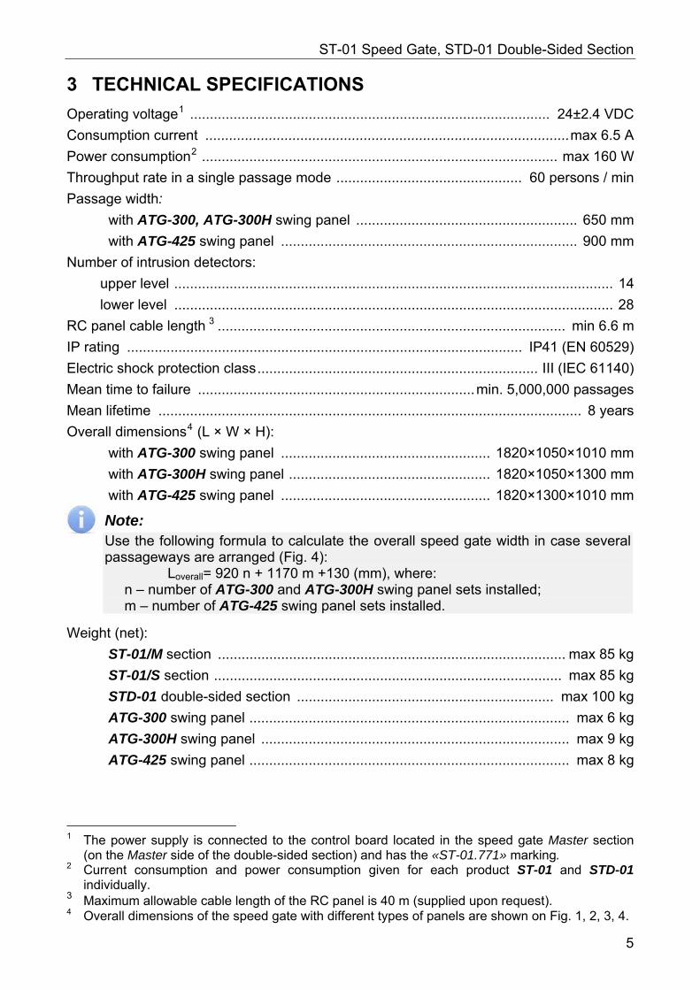
3 TECHNICAL SPECIFICATIONS
Operating voltage1 ........................................................................................... 24±2.4 VDC
Consumption current ............................................................................................max 6.5 A
Power consumption2 .......................................................................................... max 160 W
Throughput rate in a single passage mode ............................................... 60 persons / min
Passage width:
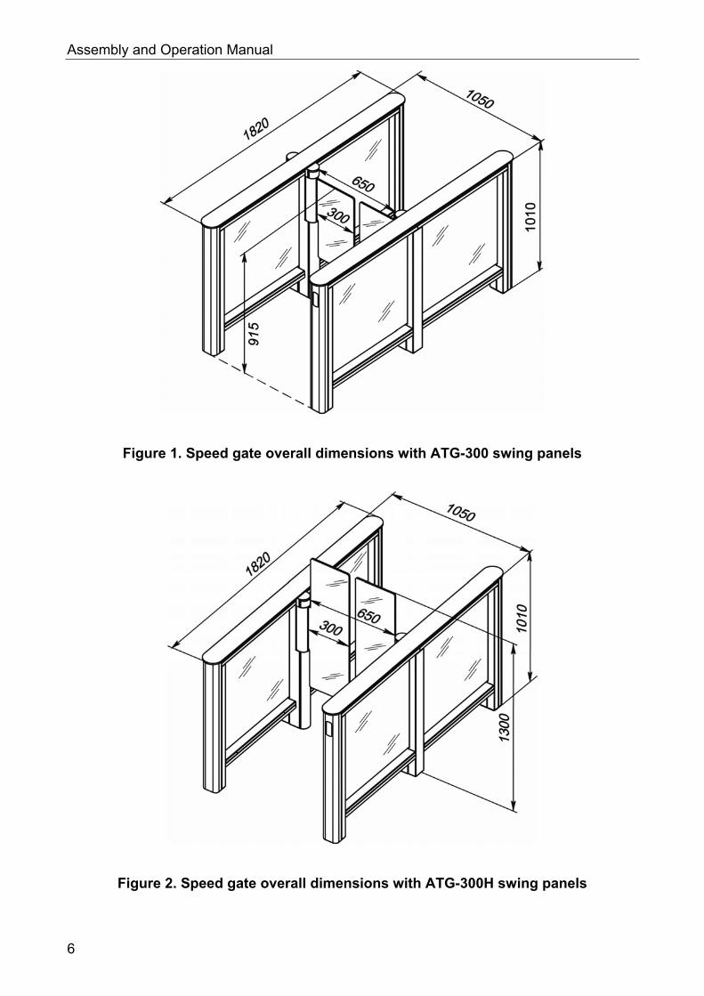
with ATG-300, ATG-300H swing panel ........................................................ 650 mm
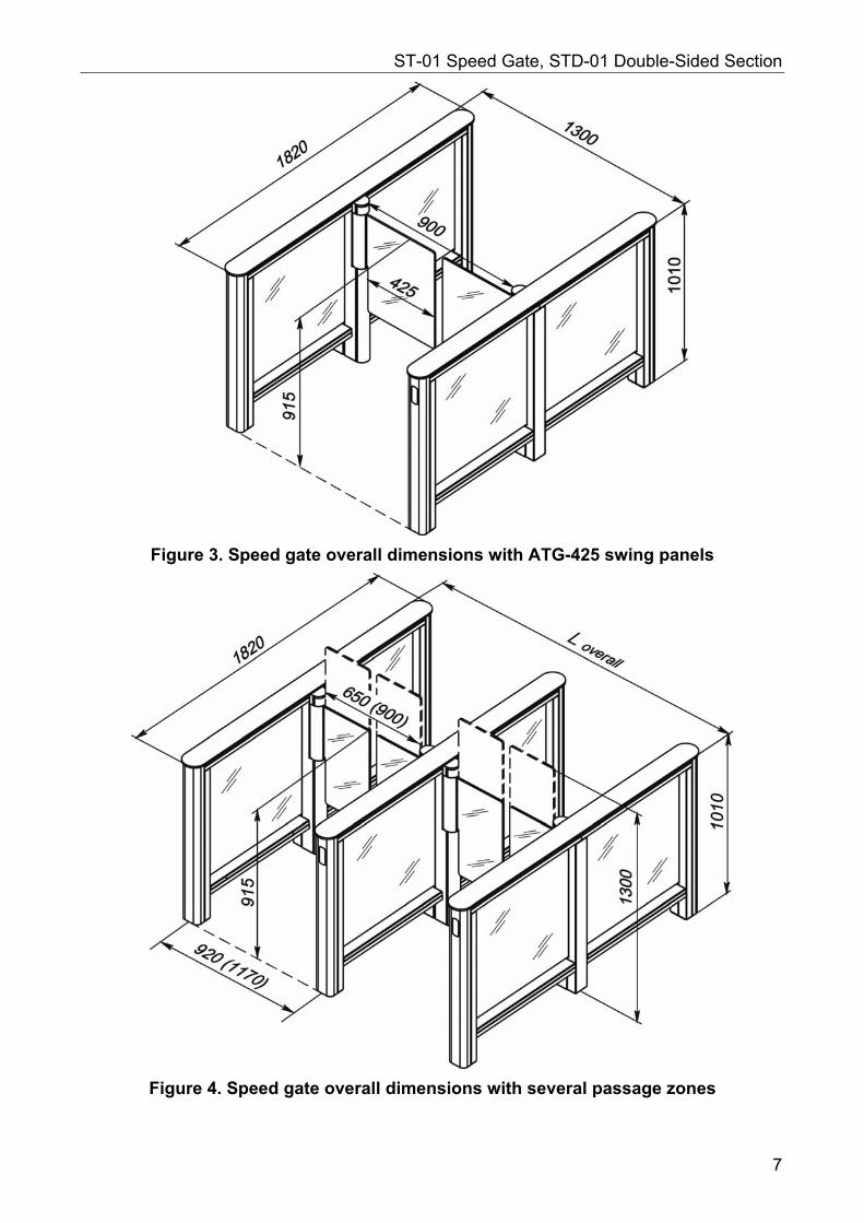
with ATG-425 swing panel ........................................................................... 900 mm
Number of intrusion detectors:
upper level ............................................................................................................... 14
lower level ............................................................................................................... 28
RC panel cable length 3 ........................................................................................ min 6.6 m
IP rating .................................................................................................... IP41 (EN 60529)
Electric shock protection class....................................................................... III (IEC 61140)
Mean time to failure ......................................................................min. 5,000,000 passages
Mean lifetime ........................................................................................................... 8 years
Overall dimensions4 (L × W × H):
with ATG-300 swing panel ..................................................... 1820×1050×1010 mm
with ATG-300H swing panel ................................................... 1820×1050×1300 mm
with ATG-425 swing panel ..................................................... 1820×1300×1010 mm
Note: Use the following formula to calculate the overall speed gate width in case several passageways are arranged (Fig. 4): Loverall= 920 n + 1170 m +130 (mm), where: n – number of ATG-300 and ATG-300H swing panel sets installed; m – number of ATG-425 swing panel sets installed.
Weight (net):
ST-01/M section ........................................................................................ max 85 kg
ST-01/S section ........................................................................................ max 85 kg
STD-01 double-sided section ................................................................. max 100 kg
ATG-300 swing panel ................................................................................. max 6 kg
ATG-300H swing panel .............................................................................. max 9 kg
ATG-425 swing panel ................................................................................. max 8 kg
1 The power supply is connected to the control board located in the speed gate Master section
(on the Master side of the double-sided section) and has the «ST-01.771» marking. 2 Current consumption and power consumption given for each product ST-01 and STD-01
individually. 3 Maximum allowable cable length of the RC panel is 40 m (supplied upon request). 4 Overall dimensions of the speed gate with different types of panels are shown on Fig. 1, 2, 3, 4.
5
Assembly and Operation Manual
Figure 1. Speed gate overall dimensions with ATG-300 swing panels
Figure 2. Speed gate overall dimensions with ATG-300H swing panels
6
ST-01 Speed Gate, STD-01 Double-Sided Section
Figure 3. Speed gate overall dimensions with ATG-425 swing panels
Figure 4. Speed gate overall dimensions with several passage zones
7
Assembly and Operation Manual
4 DELIVERY SET
4.1 Standard delivery set
4.1.1 ST-01 speed gate
Main equipment:
ST-01/M (Master)1 section .......................................................................................... 1
ST-01/S (Slave)1 section .............................................................................................. 1
glass top cover ............................................................................................................ 2
central post indication module ..................................................................................... 2
swing panel cover plate ................................................................................................4
glass swing panel ........................................................................................................ 2
Note: Swing panels are purchased separately. The type of the swing panel is chosen by the customer. The following swing panel models are available (view Fig. 1, 2, 3): ATG-300 – for 650 mm passageway arrangement; ATG-300H – increased height swing panel for 650 mm passageway arrangement; ATG-425 – for 900 mm passageway arrangement.
RC panel with cable ..................................................................................................... 1
jumper ......................................................................................................................... 3
Glass top cover mounting kit:
M5×12 bolt ..................................................................................................................16
washer (5) ..................................................................................................................16
Central post indication module mounting kit:
M5×12 bolt ................................................................................................................... 4
washer (5) ................................................................................................................... 4
Swing panel cover plate mounting kit:
M4×10 screw ............................................................................................................... 8
washer (4) ................................................................................................................... 8
Swing panel mounting kit:
M10×30 bolt ................................................................................................................ 6
M10 nut ...................................................................................................................... 6
washer 10 .................................................................................................................. 12
plastic bushing ............................................................................................................. 6
Operational documentation:
certificate ..................................................................................................................... 1
assembly and operation manual .................................................................................. 1
Packaging:
box №1 for Master section .......................................................................................... 1
box №2 for Slave section ............................................................................................ 1
box for swing panels .................................................................................................... 1
1 Both sections are delivered with dismounted swing panels, panel cover plates, central indication
modules and glass top covers (top covers are fastened to the sections with indehiscent ties).
8
ST-01 Speed Gate, STD-01 Double-Sided Section
4.1.2 STD-01 double-sided section
Main equipment:
double-sided section1 .................................................................................................. 1
glass top cover ............................................................................................................ 1
central post indication module .................................................................................... 2
swing panel cover plate ............................................................................................... 4
glass swing panel ........................................................................................................ 2
Note: Swing panels are purchased separately. The type of the swing panel is chosen by the customer. The following swing panel models are available (view Fig. 4): ATG-300 – for 650 mm passageway arrangement; ATG-300H – increased height swing panel for 650 mm passageway arrangement; ATG-425 – for 900 mm passageway arrangement.
RC panel with cable ......................................................................................................1
jumper ......................................................................................................................... 3
Glass top cover mounting kit:
M5×12 bolt ................................................................................................................... 8
washer (5) ................................................................................................................... 8
Central post indication module mounting kit:
M5×12 bolt ....................................................................................................................4
washer (5) ....................................................................................................................4
Swing panel cover plate mounting kit:
M4×10 screw .............................................................................................................. 8
washer (4) ................................................................................................................... 8
Swing panel mounting kit:
M10×30 bolt ................................................................................................................. 6
M10 nut ....................................................................................................................... 6
washer (10) ............................................................................................................... 12
plastic bushing ............................................................................................................. 6
Operational documentation:
certificate .................................................................................................................... 1
Packaging:
box №1 (for double-sided section) .............................................................................. 1
box for swing panels ................................................................................................... 1
1 The section is delivered with dismounted swing panels, panel cover plates, central indication
modules and glass top cover (top cover is fastened to the section with indehiscent ties).
9
Assembly and Operation Manual
4.2 Optional equipment The following equipment can be ordered in addition to the standard delivery set:
Speed gate mounting kit: PFG IH10 («SORMAT», Finland) anchor bolt .......................................................... 22 M10×70 bolt with internal hexagon ............................................................................ 22 washer (10) ............................................................................................................... 22
Double-sided section mounting kit (for each section): PFG IH10 («SORMAT», Finland) anchor bolt ........................................................... 14 M10×70 bolt with internal hexagon ............................................................................ 14 washer (10) ............................................................................................................... 14
Power supply unit ........................................................................... in the required quantity Wireless remote control1 ................................................................. in the required quantity
1 The WRC kit consists of a receiver, connected to the control board and a transmitter in the form
of a fob.
10
ST-01 Speed Gate, STD-01 Double-Sided Section
5 OPERATION AND DESCRIPTION
5.1 Main features
The main feature of the speed gate is the possibility of making a single passage in one direction without closing the swing panels between each passage.
The intrusion detectors are installed on two levels throughout the length of the speed gate passage zone. This allows monitoring user location inside the passage zone. The speed gate also makes it possible for several users to be in the same passage zone simultaneously.
There are several swing panel models, which can be chosen according to the passageway width and to the operation peculiarities upon making an order.
The number of the passage zones can be increased with STD-01 double-sided section installation.
In case several passage zones are arranged the front end indication modules display the passage direction.
The speed gate provides the possibility of proximity card readers installation under the glass top cover inside the posts. The glass top cover is equipped with indication module (modules), which features passage grant indication and proximity card presentation zone indication.
The speed gate features the swing panel position regulation in the initial (locked) position (teaching mode).
Indication modules of the passage grant / denial are located in the user line-of-sight range on the speed gate central post allowing quick passage completion.
The equipment provides the possibility of external indication module connection for passage grant/denial indication duplication.
Audio indication (siren) can be connected to the speed gate in order to alert the operator on the attempted unauthorized passage.
The speed gate can operate in pulse and potential modes.
The equipment can operate as an operating device as a part of ACS or as a standalone unit operated from the RC panel.
The components are made of polished stainless steel. The swing panels and the filling glass are made of tempered glass 8 -10 mm thick.
The speed gate is a normally-open device, which means that when the equipment is de-energized the swing panels freely at ±90º angle.
11
Assembly and Operation Manual
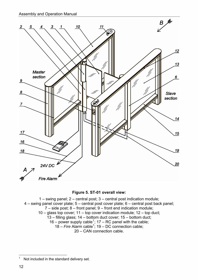
Figure 5. ST-01 overall view:
1 – swing panel; 2 – central post; 3 – central post indication module; 4 – swing panel cover plate; 5 – central post cover plate; 6 – central post back panel;
7 – side post; 8 – front panel; 9 – front end indication module; 10 – glass top cover; 11 – top cover indication module; 12 – top duct;
13 – filling glass; 14 – bottom duct cover; 15 – bottom duct; 16 – power supply cable1; 17 – RC panel with the cable;
18 – Fire Alarm cable1; 19 – DC connection cable; 20 – CAN connection cable.
1 Not included in the standard delivery set.
12
ST-01 Speed Gate, STD-01 Double-Sided Section
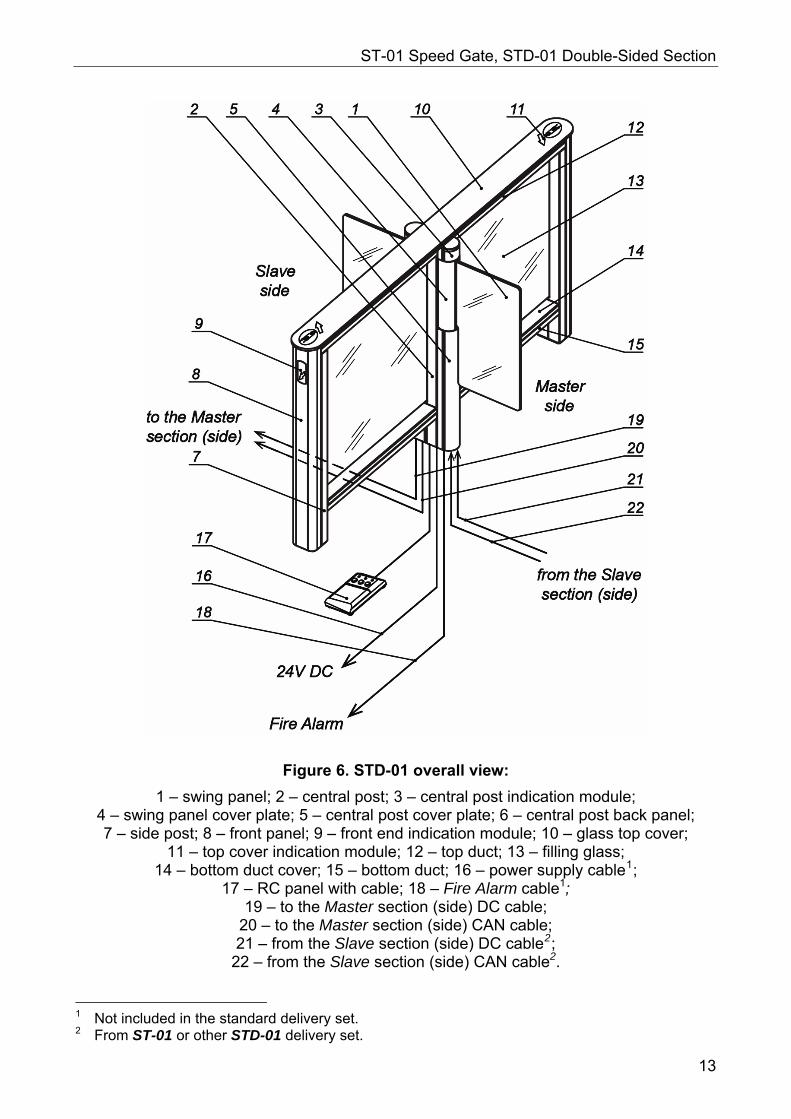
Figure 6. STD-01 overall view:
1 – swing panel; 2 – central post; 3 – central post indication module; 4 – swing panel cover plate; 5 – central post cover plate; 6 – central post back panel; 7 – side post; 8 – front panel; 9 – front end indication module; 10 – glass top cover;
11 – top cover indication module; 12 – top duct; 13 – filling glass; 14 – bottom duct cover; 15 – bottom duct; 16 – power supply cable1;
17 – RC panel with cable; 18 – Fire Alarm cable1; 19 – to the Master section (side) DC cable;
20 – to the Master section (side) CAN cable; 21 – from the Slave section (side) DC cable2;
22 – from the Slave section (side) CAN cable2.
1 Not included in the standard delivery set. 2 From ST-01 or other STD-01 delivery set.
13
Assembly and Operation Manual
5.2 Design The speed gate design is shown on Fig. 5; the double-sided section design is shown on Fig. 6. The numbers of the equipment parts are stated in the Manual in accordance with Fig. 5 and 6.
The speed gate consists of two sections, Master and Slave, and an RC panel. Each section is equipped with a motor-driven swing panel (1). Slave section is connected to Master section with two connecting cables (19, 20).
Use double-sided sections to arrange more passageways. The double-sided section is completed with an RC panel and equipped with two swing panels (1): on the Master side and on the Slave side. Each swing panel has its motor drive. Slave side is connected to the speed gate Master section or to the Master side of another double-sided section with two connection cables (19, 20). The speed gate Slave section (Slave side of the next double sided section) is connected to Master side with two connection cables (21, 22) from the standard delivery set.
5.2.1 Section
Each section consists of three posts: one central (2) and two side (7) posts. The posts are interconnected by a top duct (12) and two bottom ducts (15). Each section features a glass top cover (10), which covers a top duct. The bottom ducts are covered with bottom duct top covers (14).
The spacing between posts is completed with filling glass (13), which prevents unauthorized entry into the passage zone. Bolts, which fasten the filling glasses to the central post, are covered with central post back panel (6). Bolts, which fasten the filling glasses to the side posts, are covered with the front panels (8).
The section glass top cover is equipped with an indication module (modules) (11), which features a passage grant indicator (green arrow) and a card presentation zone indicator («a hand with a card» pictogram).
The side posts are equipped with the front end indication modules (9) showing the passage direction or passage denial (white arrow or red cross).
The central post (2) features an indication module (3) with square color indicators of passage grant / denial.
The swing panel (1) is fixed to the central post rotating support. The rotating support is covered with the central post cover plate (5). The rotating support is driven by motor, located under the swing panel cover plate (4).
The bottom part of the Master section central post features ST-01.771 speed gate control board (hereinafter – control board). The OD, the RC panel (WRC receiver), Fire Alarm device and Slave section connection cables are connected to the control board.
14
ST-01 Speed Gate, STD-01 Double-Sided Section
5.2.2 Indication modules
Each section features the following indication modules:
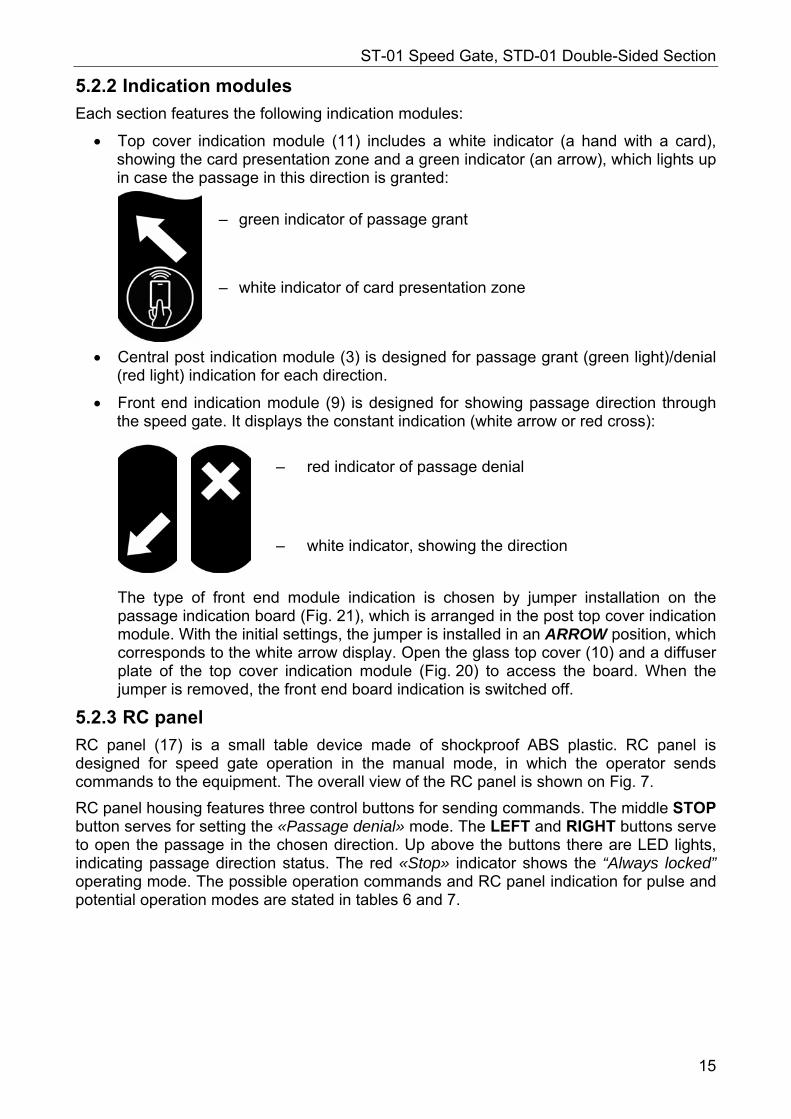
Top cover indication module (11) includes a white indicator (a hand with a card), showing the card presentation zone and a green indicator (an arrow), which lights up in case the passage in this direction is granted:
– green indicator of passage grant
– white indicator of card presentation zone
Central post indication module (3) is designed for passage grant (green light)/denial (red light) indication for each direction.
Front end indication module (9) is designed for showing passage direction through the speed gate. It displays the constant indication (white arrow or red cross):
– red indicator of passage denial
– white indicator, showing the direction
The type of front end module indication is chosen by jumper installation on the passage indication board (Fig. 21), which is arranged in the post top cover indication module. With the initial settings, the jumper is installed in an ARROW position, which corresponds to the white arrow display. Open the glass top cover (10) and a diffuser plate of the top cover indication module (Fig. 20) to access the board. When the jumper is removed, the front end board indication is switched off.
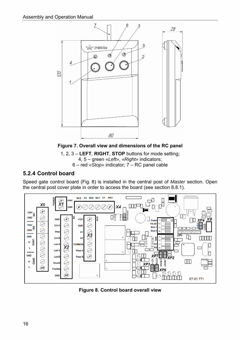
5.2.3 RC panel
RC panel (17) is a small table device made of shockproof ABS plastic. RC panel is designed for speed gate operation in the manual mode, in which the operator sends commands to the equipment. The overall view of the RC panel is shown on Fig. 7.
RC panel housing features three control buttons for sending commands. The middle STOP button serves for setting the «Passage denial» mode. The LEFT and RIGHT buttons serve to open the passage in the chosen direction. Up above the buttons there are LED lights, indicating passage direction status. The red «Stop» indicator shows the “Always locked” operating mode. The possible operation commands and RC panel indication for pulse and potential operation modes are stated in tables 6 and 7.
15
Assembly and Operation Manual
Figure 7. Overall view and dimensions of the RC panel
1, 2, 3 – LEFT, RIGHT, STOP buttons for mode setting; 4, 5 – green «Left», «Right» indicators;
6 – red «Stop» indicator; 7 – RC panel cable
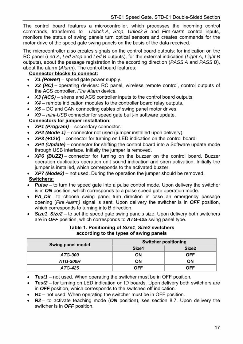
5.2.4 Control board
Speed gate control board (Fig. 8) is installed in the central post of Master section. Open the central post cover plate in order to access the board (see section 8.8.1).
Figure 8. Control board overall view
16
ST-01 Speed Gate, STD-01 Double-Sided Section
The control board features a microcontroller, which processes the incoming control commands, transferred to Unlock A, Stop, Unlock B and Fire Alarm control inputs, monitors the status of swing panels turn optical sensors and creates commands for the motor drive of the speed gate swing panels on the basis of the data received.
The microcontroller also creates signals on the control board outputs: for indication on the RC panel (Led A, Led Stop and Led B outputs), for the external indication (Light A, Light B outputs), about the passage registration in the according direction (PASS A and PASS B), about the alarm (Alarm). The control board features:
Connector blocks to connect: X1 (Power) – speed gate power supply. X2 (RC) – operating devices: RC panel, wireless remote control, control outputs of
the ACS controller, Fire Alarm device. X3 (ACS) – sirens and ACS controller inputs to the control board outputs. X4 – remote indication modules to the controller board relay outputs. X5 – DC and CAN connecting cables of swing panel motor drives. X9 – mini-USB connector for speed gate built-in software update. Connectors for jumper installation: XP1 (Program) – secondary connector. XP2 (Mode 1) – connector not used (jumper installed upon delivery). XP3 (+12V) – connector for turning on LED indication on the control board. XP4 (Update) – connector for shifting the control board into a Software update mode
through USB interface. Initially the jumper is removed. XP6 (BUZZ) – connector for turning on the buzzer on the control board. Buzzer
operation duplicates operation unit sound indication and siren activation. Initially the jumper is installed, which corresponds to the activated buzzer.
XP7 (Mode2) – not used. During the operation the jumper should be removed. Switchers: Pulse – to turn the speed gate into a pulse control mode. Upon delivery the switcher
is in ON position, which corresponds to a pulse speed gate operation mode. FA_Dir – to choose swing panel turn direction in case an emergency passage
opening (Fire Alarm) signal is sent. Upon delivery the switcher is in OFF position, which corresponds to turning into B direction.
Size1, Size2 – to set the speed gate swing panels size. Upon delivery both switchers are in OFF position, which corresponds to ATG-425 swing panel type.
Table 1. Positioning of Size1, Size2 switchers according to the types of swing panels
Switcher positioning Swing panel model
Size1 Size2
ATG-300 ON OFF
ATG-300H ON ON
ATG-425 OFF OFF
Test1 – not used. When operating the switcher must be in OFF position. Test2 – for turning on LED indication on ID boards. Upon delivery both switchers are
in OFF position, which corresponds to the switched off indication. R1 – not used. When operating the switcher must be in OFF position. R2 – to activate teaching mode (ON position), see section 8.7. Upon delivery the
switcher is in OFF position.
17
Assembly and Operation Manual
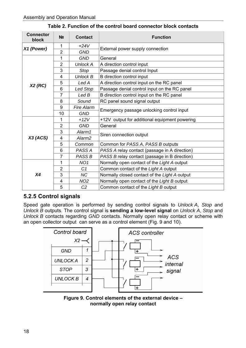
Table 2. Function of the control board connector block contacts
Connector block
№ Contact Function
1 +24V X1 (Power)
2 GND External power supply connection
1 GND General 2 Unlock A A direction control input 3 Stop Passage denial control Input 4 Unlock B B direction control input 5 Led A A direction control input on the RC panel 6 Led Stop Passage denial control input on the RC panel 7 Led B B direction control input on the RC panel 8 Sound RC panel sound signal output 9 Fire Alarm
X2 (RC)
10 GND Emergency passage unlocking control input
1 +12V +12V output for additional equipment powering 2 GND General 3 Alarm1 4 Alarm2
Siren connection output
5 Common Common for PASS A, PASS B outputs 6 PASS A PASS A relay contact (passage in A direction)
X3 (ACS)
7 PASS B PASS B relay contact (passage in B direction) 1 NO1 Normally open contact of the Light A output 2 C1 Common contact of the Light A output 3 NC Normally closed contact of the Light A output 4 NO2 Normally open contact of the Light B output
X4
5 C2 Common contact of the Light B output
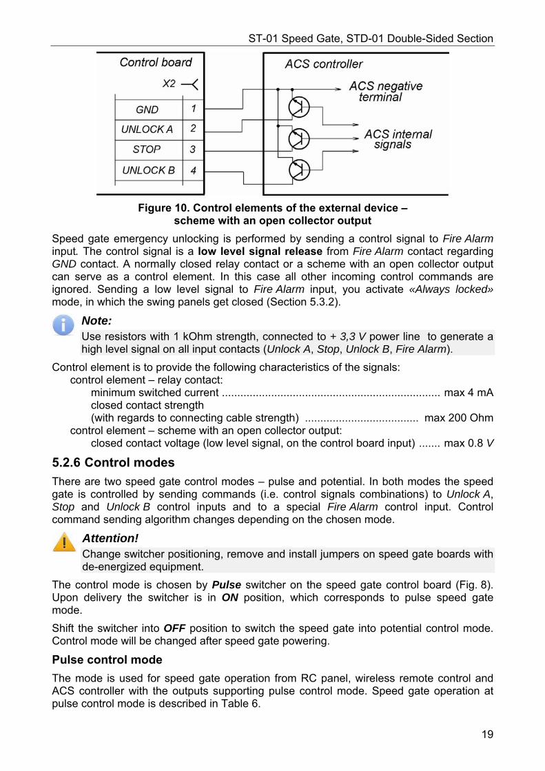
5.2.5 Control signals
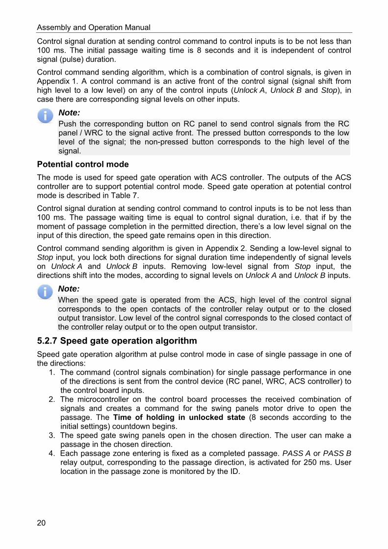
Speed gate operation is performed by sending control signals to Unlock A, Stop and Unlock B outputs. The control signal is sending a low-level signal on Unlock A, Stop and Unlock B contacts regarding GND contacts. Normally open relay contact or scheme with an open collector output can serve as a control element (Fig. 9 and 10).
Figure 9. Control elements of the external device – normally open relay contact
18
ST-01 Speed Gate, STD-01 Double-Sided Section
Figure 10. Control elements of the external device – scheme with an open collector output
Speed gate emergency unlocking is performed by sending a control signal to Fire Alarm input. The control signal is a low level signal release from Fire Alarm contact regarding GND contact. A normally closed relay contact or a scheme with an open collector output can serve as a control element. In this case all other incoming control commands are ignored. Sending a low level signal to Fire Alarm input, you activate «Always locked» mode, in which the swing panels get closed (Section 5.3.2).
Note: Use resistors with 1 kOhm strength, connected to + 3,3 V power line to generate a high level signal on all input contacts (Unlock A, Stop, Unlock B, Fire Alarm).
Control element is to provide the following characteristics of the signals: control element – relay contact:
minimum switched current ....................................................................... max 4 mA closed contact strength (with regards to connecting cable strength) ..................................... max 200 Ohm
control element – scheme with an open collector output: closed contact voltage (low level signal, on the control board input) ....... max 0.8 V
5.2.6 Control modes
There are two speed gate control modes – pulse and potential. In both modes the speed gate is controlled by sending commands (i.e. control signals combinations) to Unlock A, Stop and Unlock B control inputs and to a special Fire Alarm control input. Control command sending algorithm changes depending on the chosen mode.
Attention! Change switcher positioning, remove and install jumpers on speed gate boards with de-energized equipment.
The control mode is chosen by Pulse switcher on the speed gate control board (Fig. 8). Upon delivery the switcher is in ON position, which corresponds to pulse speed gate mode.
Shift the switcher into OFF position to switch the speed gate into potential control mode. Control mode will be changed after speed gate powering.
Pulse control mode
The mode is used for speed gate operation from RC panel, wireless remote control and ACS controller with the outputs supporting pulse control mode. Speed gate operation at pulse control mode is described in Table 6.
19
Assembly and Operation Manual
Control signal duration at sending control command to control inputs is to be not less than 100 ms. The initial passage waiting time is 8 seconds and it is independent of control signal (pulse) duration.
Control command sending algorithm, which is a combination of control signals, is given in Appendix 1. A control command is an active front of the control signal (signal shift from high level to a low level) on any of the control inputs (Unlock A, Unlock B and Stop), in case there are corresponding signal levels on other inputs.
Note: Push the corresponding button on RC panel to send control signals from the RC panel / WRC to the signal active front. The pressed button corresponds to the low level of the signal; the non-pressed button corresponds to the high level of the signal.
Potential control mode
The mode is used for speed gate operation with ACS controller. The outputs of the ACS controller are to support potential control mode. Speed gate operation at potential control mode is described in Table 7.
Control signal duration at sending control command to control inputs is to be not less than 100 ms. The passage waiting time is equal to control signal duration, i.e. that if by the moment of passage completion in the permitted direction, there’s a low level signal on the input of this direction, the speed gate remains open in this direction.
Control command sending algorithm is given in Appendix 2. Sending a low-level signal to Stop input, you lock both directions for signal duration time independently of signal levels on Unlock A and Unlock B inputs. Removing low-level signal from Stop input, the directions shift into the modes, according to signal levels on Unlock A and Unlock B inputs.
Note: When the speed gate is operated from the ACS, high level of the control signal corresponds to the open contacts of the controller relay output or to the closed output transistor. Low level of the control signal corresponds to the closed contact of the controller relay output or to the open output transistor.
5.2.7 Speed gate operation algorithm
Speed gate operation algorithm at pulse control mode in case of single passage in one of the directions:
1. The command (control signals combination) for single passage performance in one of the directions is sent from the control device (RC panel, WRC, ACS controller) to the control board inputs.
2. The microcontroller on the control board processes the received combination of signals and creates a command for the swing panels motor drive to open the passage. The Time of holding in unlocked state (8 seconds according to the initial settings) countdown begins.
3. The speed gate swing panels open in the chosen direction. The user can make a passage in the chosen direction.
4. Each passage zone entering is fixed as a completed passage. PASS A or PASS B relay output, corresponding to the passage direction, is activated for 250 ms. User location in the passage zone is monitored by the ID.
20
ST-01 Speed Gate, STD-01 Double-Sided Section
Note: In order to prevent contact with the swing panels, the speed gate is equipped with the danger zone detection. When user enters the danger zone, the swing panels turning (opening or closing) is blocked. Danger zone range varies depending on the swing panels dimensions.
5. After the user passes through the open swing panels he gets into a safe zone (zone, in which it is impossible to get in contact with the swing panels) and the control board microcontroller sends a command for the motor drive to close the swing panels. The swing panels get closed.
6. If at the moment of passage performance by the first user there’s been an authorization of a new user in the same passage direction, the swing panels won’t get closed and the new user will be able to follow the first one.
7. If at the moment of passage performance through the passage zone there’s been an authorization of a new user in an opposite passage direction, then after the first user passage completion the swing panels will be closed and open in the opposite direction for the second user to pass.
Note: In order to increase passageway effectiveness it is recommended to arrange separate passage zones for each direction. Passage directions for each passage zone can be displayed on the front end indication modules.
8. If the user does not enter the passage zone during the Time of holding in unlocked state, the swing panels will close the passage zone.
9. After the passage is completed and the swing panels are closed, the speed gate is ready for another passage.
At potential speed gate control mode, the control signal can be released after receiving a signal from PASS output for the same direction.
5.3 Operation devices Speed gate operation can be performed from the following devices: RC panel / WRC; ACS controller, Fire Alarm device. These devices can be connected to the turnstile separately, simultaneously or in any combination with each other.
In case several control devices are connected simultaneously there can be a control signal overlap. In this case speed gate will operate according to the command, generated by the signal combination (Appendixes 1 and 2).
5.3.1 RC panel connection
RC panel is connected with a flexible multicore cable to Unlock A, Stop, Unlock B, Led A, Led Stop, Led B, Sound and GND contacts of the X2 connector block according to the speed gate connection layout (Fig. 17).
Note: WRC is connected to Unlock A, Stop, Unlock B and GND contacts of the X2connector block. Power supply of the WRC is connected to +12V contact of the X3 connector block.
21
Assembly and Operation Manual
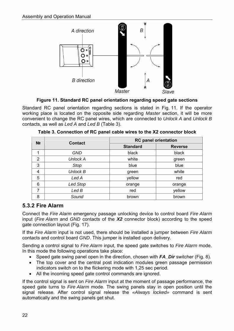
Figure 11. Standard RC panel orientation regarding speed gate sections
Standard RC panel orientation regarding sections is stated in Fig. 11. If the operator working place is located on the opposite side regarding Master section, it will be more convenient to change the RC panel wires, which are connected to Unlock A and Unlock B contacts, as well as Led A and Led B (Table 3).
Table 3. Connection of RC panel cable wires to the X2 connector block
RC panel orientation № Contact
Standard Reverse
1 GND black black
2 Unlock A white green
3 Stop blue blue
4 Unlock B green white
5 Led A yellow red
6 Led Stop orange orange
7 Led B red yellow
8 Sound brown brown
5.3.2 Fire Alarm
Connect the Fire Alarm emergency passage unlocking device to control board Fire Alarm input (Fire Alarm and GND contacts of the X2 connector block) according to the speed gate connection layout (Fig. 17).
If the Fire Alarm input is not used, there should be installed a jumper between Fire Alarm contacts and control board GND. This jumper is installed upon delivery.
Sending a control signal to Fire Alarm input, the speed gate switches to Fire Alarm mode. In this mode the following operations take place:
Speed gate swing panel open in the direction, chosen with FA_Dir switcher (Fig. 8). The top cover and the central post indication modules green passage permission
indicators switch on to the flickering mode with 1,25 sec period. All the incoming speed gate control commands are ignored.
If the control signal is sent on Fire Alarm input at the moment of passage performance, the speed gate turns to Fire Alarm mode. The swing panels stay in open position until the signal release. After control signal release the «Always locked» command is sent automatically and the swing panels get shut.
22
ST-01 Speed Gate, STD-01 Double-Sided Section
5.3.3 Operation from the ACS
Operating as a part of the ACS, the speed gate can serve as an operating device. Speed gate also provides an opportunity of built-in proximity card readers installation under the glass top cover.
ACS controller outputs are connected to Unlock A, Stop, Unlock B and GND contacts of the X2 connector block. ACS controller inputs are connected to PASS A, PASS B and to Common contacts of the X3 connector block. Connection is made in accordance with the speed gate connection layout (Fig. 17).
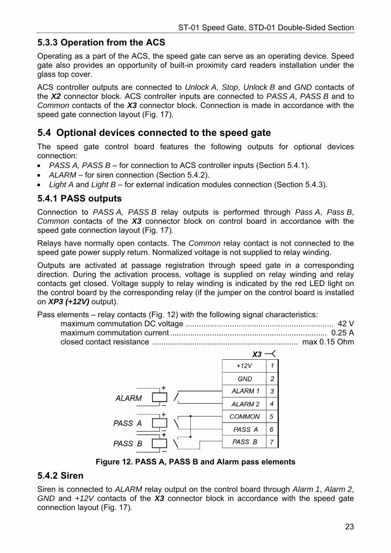
5.4 Optional devices connected to the speed gate The speed gate control board features the following outputs for optional devices connection: PASS A, PASS B – for connection to ACS controller inputs (Section 5.4.1). ALARM – for siren connection (Section 5.4.2). Light A and Light B – for external indication modules connection (Section 5.4.3).
5.4.1 PASS outputs
Connection to PASS A, PASS B relay outputs is performed through Pass A, Pass B, Common contacts of the X3 connector block on control board in accordance with the speed gate connection layout (Fig. 17).
Relays have normally open contacts. The Common relay contact is not connected to the speed gate power supply return. Normalized voltage is not supplied to relay winding.
Outputs are activated at passage registration through speed gate in a corresponding direction. During the activation process, voltage is supplied on relay winding and relay contacts get closed. Voltage supply to relay winding is indicated by the red LED light on the control board by the corresponding relay (if the jumper on the control board is installed on XP3 (+12V) output).
Pass elements – relay contacts (Fig. 12) with the following signal characteristics: maximum commutation DC voltage ................................................................... 42 V maximum commutation current ....................................................................... 0.25 A closed contact resistance .................................................................. max 0.15 Ohm
Figure 12. PASS A, PASS B and Alarm pass elements
5.4.2 Siren
Siren is connected to ALARM relay output on the control board through Alarm 1, Alarm 2, GND and +12V contacts of the X3 connector block in accordance with the speed gate connection layout (Fig. 17).
23
Assembly and Operation Manual
Normalized voltage is not supplied on relay winding and the relay contacts are open. Output is activated when ID registers an unauthorized passage. During the activation process, voltage is supplied on relay winding and relay contacts get closed. Voltage supply to relay winding is indicated by the red LED light on the control board by the corresponding relay (if the jumper on the control board is installed on XP3 (+12V) output).
Pass elements – relay contacts (Fig. 12) with the following signal characteristics: maximum commutation DC voltage ................................................................... 42 V maximum commutation current ...................................................................... 0,25 A closed contact resistance .................................................................. max 0,15 Ohm
Maximum consumption current of the siren, connected to the contact +12V of the X3 connector block on control board should not exceed 0.3 A.
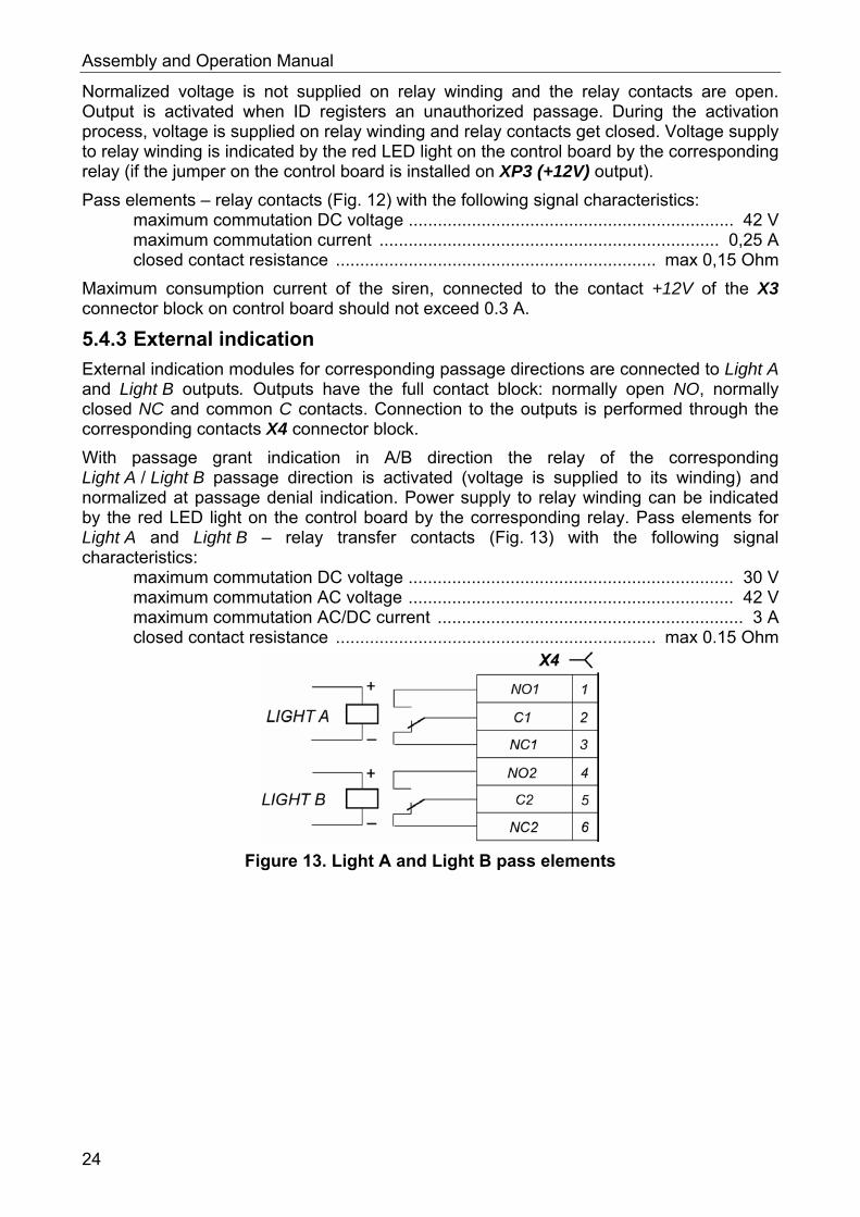
5.4.3 External indication
External indication modules for corresponding passage directions are connected to Light A and Light B outputs. Outputs have the full contact block: normally open NO, normally closed NC and common C contacts. Connection to the outputs is performed through the corresponding contacts X4 connector block.
With passage grant indication in A/B direction the relay of the corresponding Light A / Light B passage direction is activated (voltage is supplied to its winding) and normalized at passage denial indication. Power supply to relay winding can be indicated by the red LED light on the control board by the corresponding relay. Pass elements for Light A and Light B – relay transfer contacts (Fig. 13) with the following signal characteristics:
maximum commutation DC voltage ................................................................... 30 V maximum commutation AC voltage ................................................................... 42 V maximum commutation AC/DC current ............................................................... 3 A closed contact resistance .................................................................. max 0.15 Ohm
Figure 13. Light A and Light B pass elements
24
ST-01 Speed Gate, STD-01 Double-Sided Section
6 MARKING AND PACKAGING Each speed gate section has a marking sticker on the internal surface of the section top duct. To access the marking sticker open the glass top cover (Fig. 24). The sticker contains trademark and contact details of the manufacturer, section name and product serial number, date of manufacture, power supply voltage and speed gate power input.
Speed gate Master section and double-sided section also have the sticker on the internal surface of the central post cover plate (5). Open the post cover plate to access the sticker (Fig. 18). The sticker contains speed gate connection layout corresponding to the one on Figure 17.
Speed gate in a standard delivery set is packed in transportation boxes, protecting it from being damaged during transportation and storage. The number of boxes depends on the ordered delivery set.
Transportation boxes dimensions (length × width × height): ST-01:
№1 (ST-01/M section) ................................................................ 196×36×111 cm №2 (ST-01/S section) ................................................................ 196×36×111 cm
STD-01: №1 (double-sided section).......................................................... 196×36×111 cm
ATG-300 (set of swing panels) ............................................................... 78×48×12 cm ATG-300H (set of swing panels) ..........................................................116×48×12 cm ATG-425 (set of swing panels) ............................................................... 78×60×12 cm
Transportation boxes weight (gross): ST-01:
№1 (ST-01/M section) ...................................................................... max 125 kg №2 (ST-01/S section) ...................................................................... max 125 kg
STD-01: №1 (double-sided section) ............................................................... max 140 kg
ATG-300 (set of swing panels) ................................................................... max 16 kg ATG-300H (set of swing panels) ................................................................ max 21 kg ATG-425 (set of swing panels) ................................................................... max 19 kg
25
Assembly and Operation Manual
7 SAFETY REQUIREMENTS
7.1 Installation safety requirements Speed gate installation is to be performed by qualified personnel after careful study of this Manual with observance of general safety rules.
Attention! All works should be performed only after the power supply is switched off and
disconnected from the AC mains. Only serviceable tools should be used for installation. During the installation before the speed gate is fixed to the floor be careful not to
drop the housing. Before the first speed gate power-up make sure installation and all connections
are done properly.
Power supply installation should be performed with observance of safety rules, given in its operation manual.
7.2 Operation safety requirements Observe general electrical safety rules when operating the turnstile.
Attention! Do not use the speed gate in conditions that do not comply with the requirements
given in Section 2. Do not use the speed gate at supply voltage that does not comply with the
requirements given in Section 3.
Power supply unit must be operated with observance of safety requirements mentioned in its certificate.
26
ST-01 Speed Gate, STD-01 Double-Sided Section
8 INSTALLATION Speed gate installation should be performed with observance of safety rules described in Section 7.1.
Speed gate installation should be carried out by, at least, two qualified professionals who have accurately studied the following manual. Carefully study this section before the installation and follow it thereafter.
8.1 Installation details
Attention! During speed gate section installation leave a 70 mm space between the section back panel and the wall in order to provide the possibility of central post back panel disassembly.
It is recommended: to mount the speed gate on steady and level concrete (grade 400 or higher,
strength class B22.5), stone or similar foundations at least 150 mm thick. to level the foundation so that the anchoring points of the speed gate lie in one
plane (check it with a level). to apply reinforcing elements (450×450×200 mm) in case the speed gate is installed
on a less steady foundation.
8.2 Installation tools Use the following tools during the installation:
hammer drill 1.21.5 kW; hard-alloyed drill bit Ø16 mm for anchor bolt sleeves; floor chaser for cable raceways; Philips screwdriver PH2; open-end and socket wrenches S17; hexagon keys SW2, SW4, SW5; ratchet wrench with socket head (for tightening anchors) level; measuring tape 2 m; slide caliper.
Note: It is allowed to use other equipment and measuring tools provided the equipment in use ensures the required parameters and measurement accuracy.
8.3 Cable length Table 4. Cables, used at the installation
№ Equipment Cable
length, m,max
Cable type Cross-
section, mm, min
Example
10 Twin cable 1.5 AWG 15; HO5VV-F 2×1.5 1 Power supply
20 Twin cable 2.5 AWG 13; HO5VV-F 2×2.5
2 - Fire Alarm - Optional equipment to control board input and output
30 Twin cable 0.2 RAMCRO SS22AF-T 2×0.22 CQR-2
3 RC panel 40 Eight core cable 0.2 CQR CABS8 8×0.22c 4 ACS controller 30 Six core cable 0.2 CQR CABS6 6×0.22c
27
Assembly and Operation Manual
8.4 Installation order
Attention! The manufacturer shall not be liable for any damage caused by the improper installation and declines any claims arising thereof in case the installation is not done in compliance with the instructions provided in this Manual.
Installation order is described with regards to recommendations, given in Section 8.1. Installation tools are listed in Section 8.2. Figure numbers are given in accordance with Fig. 5 and 6.
Speed gate connection layout is given in Fig. 17. Types of cables used are stated in Section 8.3. The example of ST-01 and STD-01 connection scheme with extra passageway arrangement is depicted at Fig. 16.
Follow this order to install the speed gate:
1. Install the speed gate power supply unit in its space.
Attention! Moving the speed gate posts from one place to another, don’t hold the
equipment for its glass top cover (10). Mount and install speed gate sections after cable laying in electric raceway and
inside the sections. During the speed gate disassembly before the sections are fixed on the
installation surface, be careful to keep the sections from falling, and the parts of sections from damage.
2. Choose the installation places for Master and Slave sections, if needed choose the installation places for the double-sided sections. Note that opposite to the STD-01 Master section swing panel there should be STD-01 Slave section.
3. Mark and prepare the holes as per the schemes given in Fig. 14-15 for the anchor bolts to fix the turnstile and the STD-01 double-sided section to the floor. Make the holes with carbide drill Ø16. Drill depth should be 60 mm.
4. Prepare the cable duct in the floor: ducts for cabling from the external devices (power supply, RC panel or ACS
controller, Fire Alarm device and other) to the holes for Master section input and for double-sided section of the Master side cabling;
ducts, which connect holes for opposite sections cabling (double-sided section sides) of one passageway – for DC and CAN cabling.
Attention!
Passage zones, limited by side sections and/or by the sides of the double-sided section are functioning separately, unconnected to each other.
Master and Slave sides of the double-sided section are electrically independent as they refer to different passage zones.
5. Make the cabling in the ducts from external devices to the installation places of the sections. Between the opposite sections (sides of sections)of each passage in the duct make the cord for pulling DC and CAN cables from Slave section (sides of section) to Master section (sides of section).
28
ST-01 Speed Gate, STD-01 Double-Sided Section
Note:
In case there is no opportunity to make the cord for pulling cables with a duct, DC and CAN cables can be laid from the very beginning, before the installation of the sections. These cables are in the central post of the Slave section (sides of the section) down under the cover plate. In order to do that unpack the Slave section, take off the cover plate from the central post (Fig. 18), pull out DC and CAN cables and disconnect them from the control board with a drive control board. At each end of the wire core there are numeric markers, corresponding to the connection scheme (Fig. 17).
6. Install anchor sleeves from the delivery set in the holes so that they do not project above the surface of the floor.
7. Unpack Master section (box №1, ST-01/M). Two people should perform all the works! Take the section out of the box for the upper duct (not for the glass top cover sides).
8. Take off the glass top cover, fixed at the section with the indehiscent buckles and place it on the even and steady surface.
Attention!
Be careful! Don’t drop the top cover during the assembly process, don’t damage the glass and the tape on the inner surface of the cover.
9. Remove two steel shielding plates located under glass cover in the upper duct (Fig. 23) and put them aside.
10. Disassemble the parts of the turnstile sections in the following order: Disassemble the central post cover plate (5) (Fig.18, part 8.8.1). Disassemble the front panels of both side posts (8) (Fig. 19, part 8.8.2).
11. Install the section on the anchor sleeves. Two people should perform all the works!
12. Through the cabling hole in the Master section central post pull inside the post the following cables: from the power supply (16), from RC panel (17), from Fire Alarm device(18) and supplementary equipment, as well as the cord for pulling DC (19) and CAN (20) cables on the Slave section (sides of section).
13. Using a level, place the section in a vertical position. Use mounting gaskets. The deviation of the section from the vertical in the longitudinal plane should not be more than 0.5º.
14. With a ratchet wrench with socket head, fix the section on the mounting surface with 11 M10 bolts with washers.
Note: Paragraphs 14 - 19 should be performed in case the additional double-sided STD-01sections are installed.
15. Unpack and mount the double-sided section. Follow the instructions described in par. 7 - 10 (for both sides of the section), place the double-sided section so that its Slave side is opposite to the installed Master section.
16. Take out the DC and CAN cables from the central post of the double-sided section (from the Slave side). Pull them out through the hole for cable input in the post foundation. Pull the cables with cord for pulling cables duct through cable duct of the Master section.
29
Assembly and Operation Manual
17. Through the hole for cable input in the central post foundation of the double-sided section (from Master side) pull inside the post cables for passage area control: from the power supply, from RC panel or ACS controller, from Fire Alarm device and supplementary equipment as well as the cord for pulling DC and CAN cables from Slave section.
18. Place the section in a vertical position (par. 12).
19. With a ratchet wrench with socket head, fix the section on the mounting surface with 14 M10 bolts with washers.
20. Install other double-sided sections if needed (par. 14-18).
21. Unpack and install speed gate Slave section. Follow the instructions given in par. 7-10.
22. Take out the DC and CAN cables from the central post of central section (from the Slave side). Pull them out through the hole for cable input in the post foundation. Pull the cables with cord for pulling cables duct through cable duct of the Master section.
23. Using a level, place the section in a vertical position and fix it on the installation surface (par. 12-13).
24. Connect the cables to the speed gate control board, which is situated at the bottom part of the central post of Master section according to the electrical connections scheme of the turnstiles (Fig. 8 and Fig. 17).
Note: DC (2) and CAN (4) connecting cables are connected to the X5 terminal block of the Master section control board according to the marking of their wire cores.
25. If needed, install the proximity card readers into the special places, situated in the upper duct under the indication modules of the top cover. Fix the readers with double sided tape. In order to make the installation easier you may also disassemble the indication modules of the top cover (Fig. 20, Section 8.8.3). Pull the reader cable through the upper duct and the central post to the place for cable input from ACS controller, using the gaps, specially designed in the section housing. Use self-adhesive cable tie mount to fix the cables. Do not fix the cables to internal wiring and to intrusion detector boards. Do not lay the cables on that side of the board, at which the sensors are located.
Attention! The speed gate post is designed for PERCo proximity card readers installation. In order to install readers, manufactured by other companies, please note that they are to comply with the following characteristics: dimensions (length × width × height) .................................. max 155×68×28 mm card reading distance ......................................................................... min 40 mm
26. Check the accuracy of all the electrical connections.
27. Install the front panels of the side sections at their places (8) (Section 8.8.2). After finishing the installation check if the upper end of the installed front panel is located on the same level with the turnstile housing. Panels with front end indication module are installed from that side of the section, at which the top cover indication modules are located. Pull the connecting cable from the turnstile top duct and connect it to the front end indication module.
30
ST-01 Speed Gate, STD-01 Double-Sided Section
28. To change the indication type on the front end indication modules to the «red cross» install the XP4 jumper in the top cover indication module of this section (Sections 5.5.2, 8.8.3, the jumper positioning is shown at Fig. 21).
29. Using the switches on Master section (side of the section) control board (Section 5.2.4): Set the speed gate operation mode with the Pulse switcher. Choose the swing panels opening direction by sending a signal from Fire Alarm
device, using FA Dir switcher. Set the type of swing panels for this turnstile using Size1, Size2 switchers
(Table. 1).
30. Unpack the swing panels (1) and install them (Fig. 22, Section 8.8.4).
31. Check the intrusion detector functioning following these instructions: Turn the Test 2 switcher on the control board ON. Actuate the turnstile as per Section 9.1. Check the LEDs on intrusion detector board, located in the top (12) and bottom
(15) ducts of Master and Slave sections (before checking remove the top covers in the bottom ducts, Section 8.8.8):
o In the normalized condition of the intrusion detectors the LEDs of the Slave section boards should be dark, while at the Master section boards they should light continuously.
o In case of disconnection between intrusion detector board and the control board, intrusion detector LEDs will start blinking – check DC (19) and CAN (20) cables connection in the terminal blocks.
Check the corresponding LEDs lighting up on the Slave section when performing the overlap of the intrusion detector optical axises through the whole length of the passage area on the upper and lower levels.
Deactivate the turnstile in the order, reverse to the actuation order. Turn the Test 2 switcher on the control board OFF.
32. Install all the parts of the turnstiles as follows (Section 8.8): Install the central post cover plates (5) (Section 8.8.1). Install the swing panels cover plates (4) (Fig. 22, Section 8.8.5, included in the
tool set). Install indication modules of the central posts (3) (Fig. 23, Section 8.8.6),
included in the tool set. Install two shielding plates (Fig. 23, Section 8.8.6). Install the glass top covers (10) (Fig. 24, Section 8.8.7).
33. Make the test actuation as per Section 9.1.
34. Switch the turnstile into teaching mode and manually install the swing panels into initial (closed) position as per Section 8.7 to level the swing panels relative to each other.
35. Check the locking pins, serving to mechanically lock the turn of each swing panel. In order to do that, shift the needed swing panel from the initial position. Check the operation of the locking pin by the specific sound.
36. Check the speed gate operation by sending control commands from the RC panel (Section 9.2, 9.3).
37. Do accordingly (as per par. 23 – 34) for all other double-sided sections installed.
After installation and testing, the speed gate is ready for operation.
31
Assembly and Operation Manual
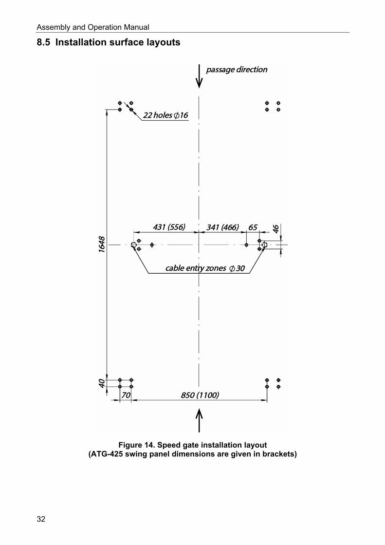
8.5 Installation surface layouts
Figure 14. Speed gate installation layout (ATG-425 swing panel dimensions are given in brackets)
32
ST-01 Speed Gate, STD-01 Double-Sided Section
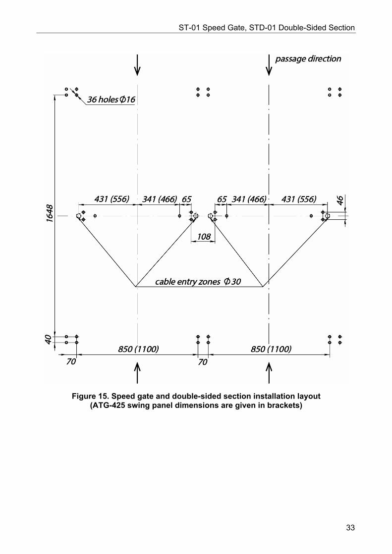
Figure 15. Speed gate and double-sided section installation layout (ATG-425 swing panel dimensions are given in brackets)
33
Assembly and Operation Manual
8.6 Speed gate connection layout
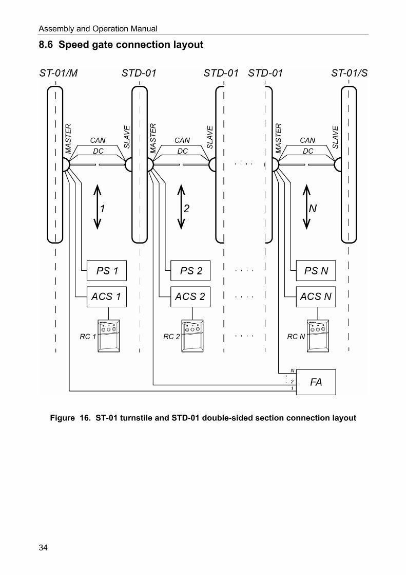
Figure 16. ST-01 turnstile and STD-01 double-sided section connection layout
34
ST-01 Speed Gate, STD-01 Double-Sided Section
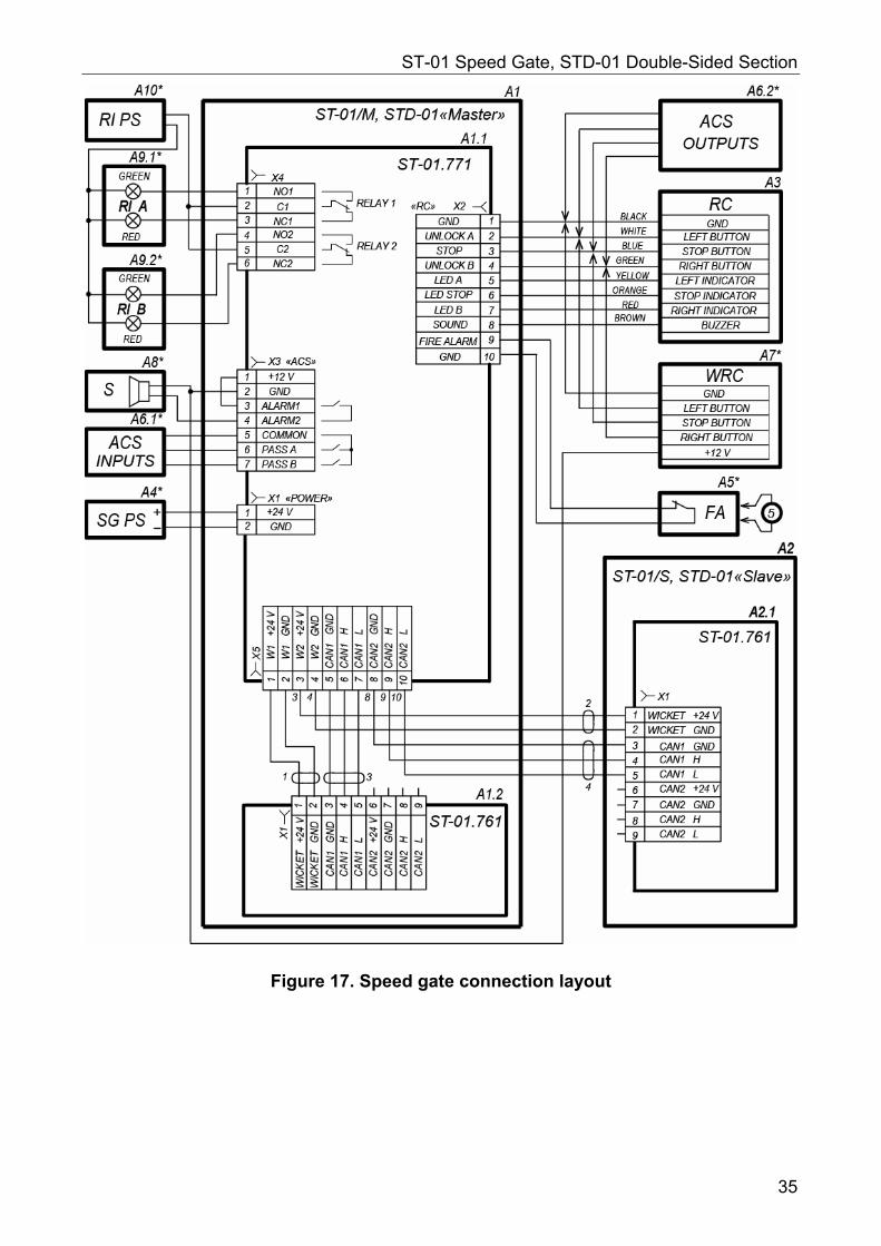
Figure 17. Speed gate connection layout
35
Assembly and Operation Manual
Table 5. List of the elements of speed gate connection layout
Legend Name Nr, pc.
A1 Master section (section side) 1
A1.1 Control board ST-01.771 1
A1.2 Drive control board ST-01.761, Master section (section side) 1
A2 Slave section (section side) 1
A2.1 Drive control board ST-01.761, Slave section (section side) 1
A3 RC panel 1
A411 Speed gate power supply 1
A51 FireAlarm signal sending device 1
A6.11, A6.21 ACS controller 1
A71 Wireless remote control 1
A81 12V DC siren 1
A9.11, A9.21 Remote indication module 2
A101 Remote indicators power supply 1
1, 2 DC connecting cable 2
3, 4 CAN connecting cable 2
5 Jumper with a conductor, in case there is no Fire Alarm (A5). Installed. 1
8.7 Teaching mode The mode provides the possibility of turnstile swing gates initial position manual regulation. Do the following to activate the mode:
1 Turn off the turnstile power supply. 2 Turn ON the R2 switch on the control board. 3 Arrange the swing panels into the required initial position and adjust them relative to
each other. 4 Turn on the turnstile power supply. The swing panel will make a search for the end
positions and get back into the initial position. The swing panel position data will be registered in the control board memory.
Note:
In the teaching mode the turnstile switch into the “Emergency” mode indicates the incorrect initial position of the swing panels. Turn off the turnstile power supply in order to exit the “Emergency” mode. In order to continue with the teaching mode, install the swing panels into the initial (locked) position and turn on the turnstile power supply.
5 Turn off the turnstile power supply. 6 Turn OFF the R2 switch on the control board. 7 Turn on the turnstile power supply. The swing panels will make a search for the end
positions and get back into the initial (locked) position. The turnstile is ready for operation.
11 The equipment is not included in the standard delivery set.
36
ST-01 Speed Gate, STD-01 Double-Sided Section
8.8 Assembly and disassembly of the turnstile components
Attention!
Turnstile components are made of polished stainless steel and glass. Be careful during the assembly, to prevent the components from falling and damage, place them on the even and steady surface, prevent them from scratches.
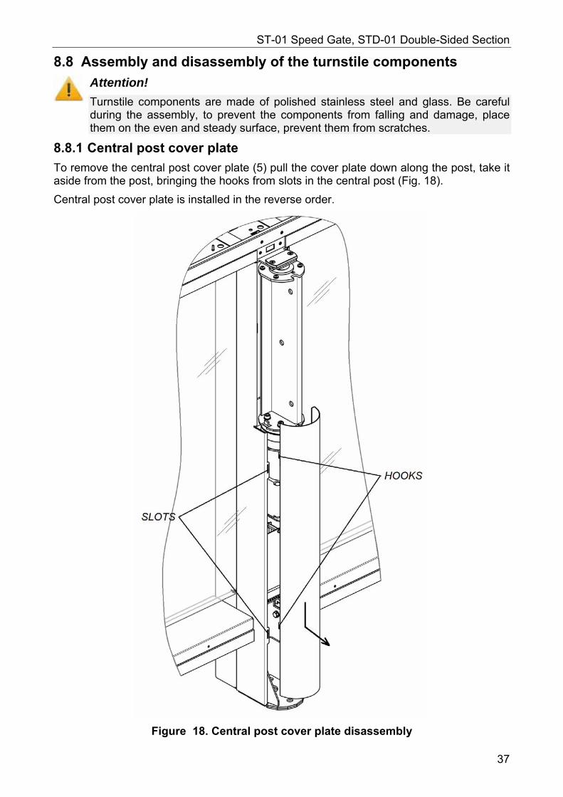
8.8.1 Central post cover plate
To remove the central post cover plate (5) pull the cover plate down along the post, take it aside from the post, bringing the hooks from slots in the central post (Fig. 18).
Central post cover plate is installed in the reverse order.
Figure 18. Central post cover plate disassembly
37
Assembly and Operation Manual
8.8.2 Front panel of the side post
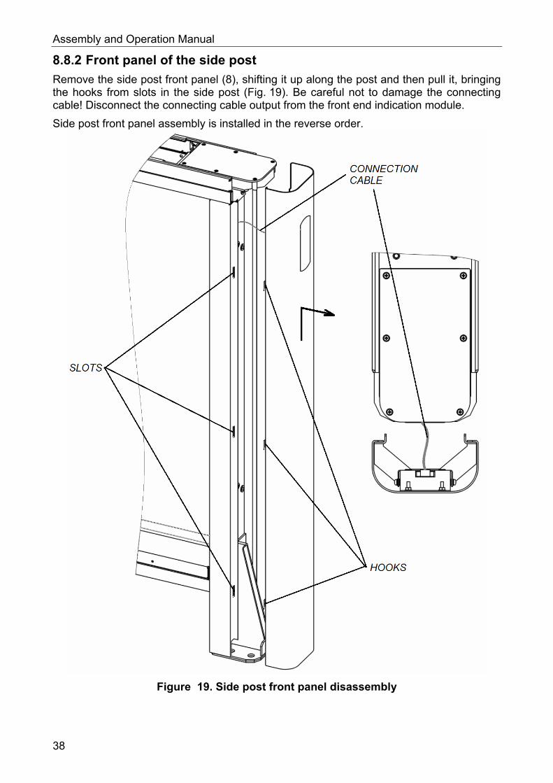
Remove the side post front panel (8), shifting it up along the post and then pull it, bringing the hooks from slots in the side post (Fig. 19). Be careful not to damage the connecting cable! Disconnect the connecting cable output from the front end indication module.
Side post front panel assembly is installed in the reverse order.
Figure 19. Side post front panel disassembly
38
ST-01 Speed Gate, STD-01 Double-Sided Section
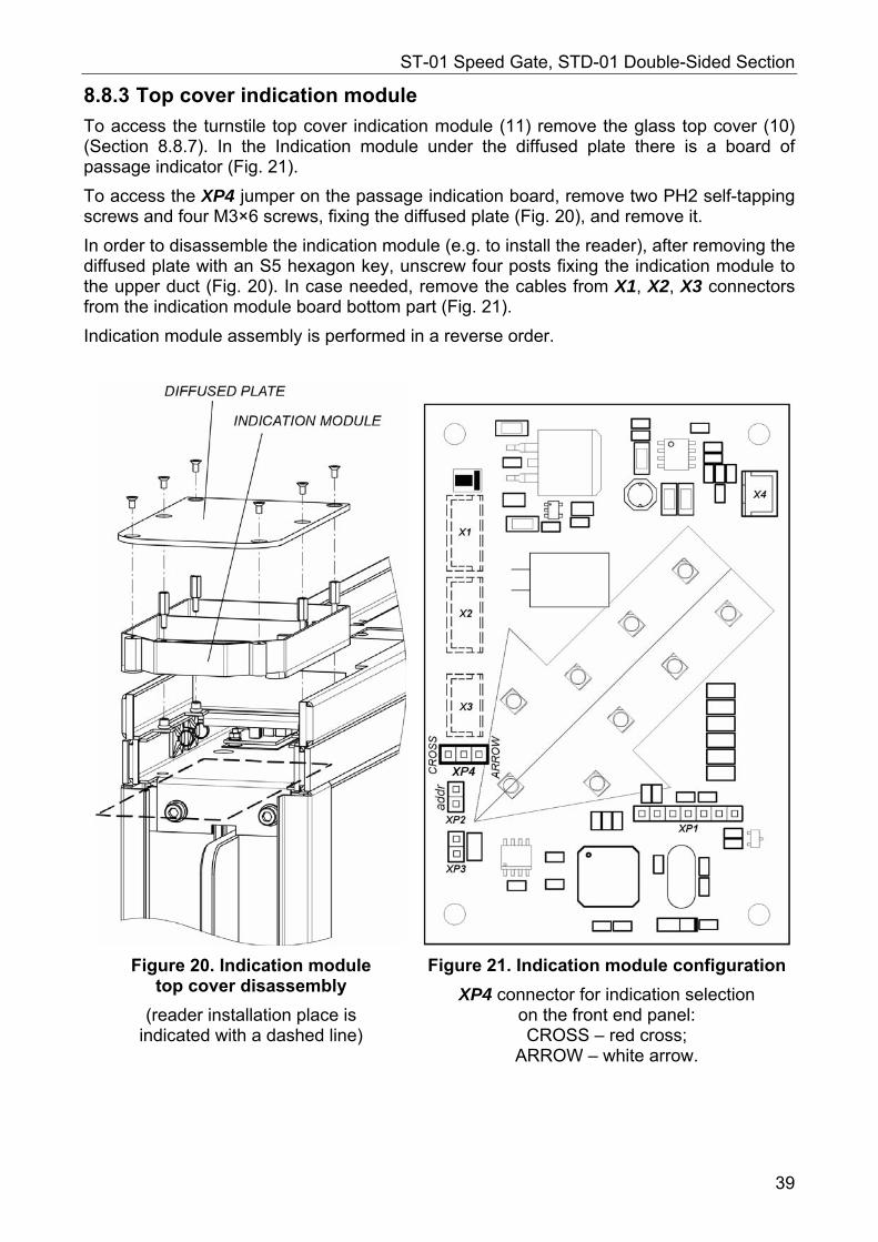
8.8.3 Top cover indication module
To access the turnstile top cover indication module (11) remove the glass top cover (10) (Section 8.8.7). In the Indication module under the diffused plate there is a board of passage indicator (Fig. 21).
To access the XP4 jumper on the passage indication board, remove two PH2 self-tapping screws and four M3×6 screws, fixing the diffused plate (Fig. 20), and remove it.
In order to disassemble the indication module (e.g. to install the reader), after removing the diffused plate with an S5 hexagon key, unscrew four posts fixing the indication module to the upper duct (Fig. 20). In case needed, remove the cables from X1, X2, X3 connectors from the indication module board bottom part (Fig. 21).
Indication module assembly is performed in a reverse order.
Figure 20. Indication module top cover disassembly
(reader installation place is indicated with a dashed line)
Figure 21. Indication module configuration
XP4 connector for indication selection on the front end panel: CROSS – red cross;
ARROW – white arrow.
39
Assembly and Operation Manual
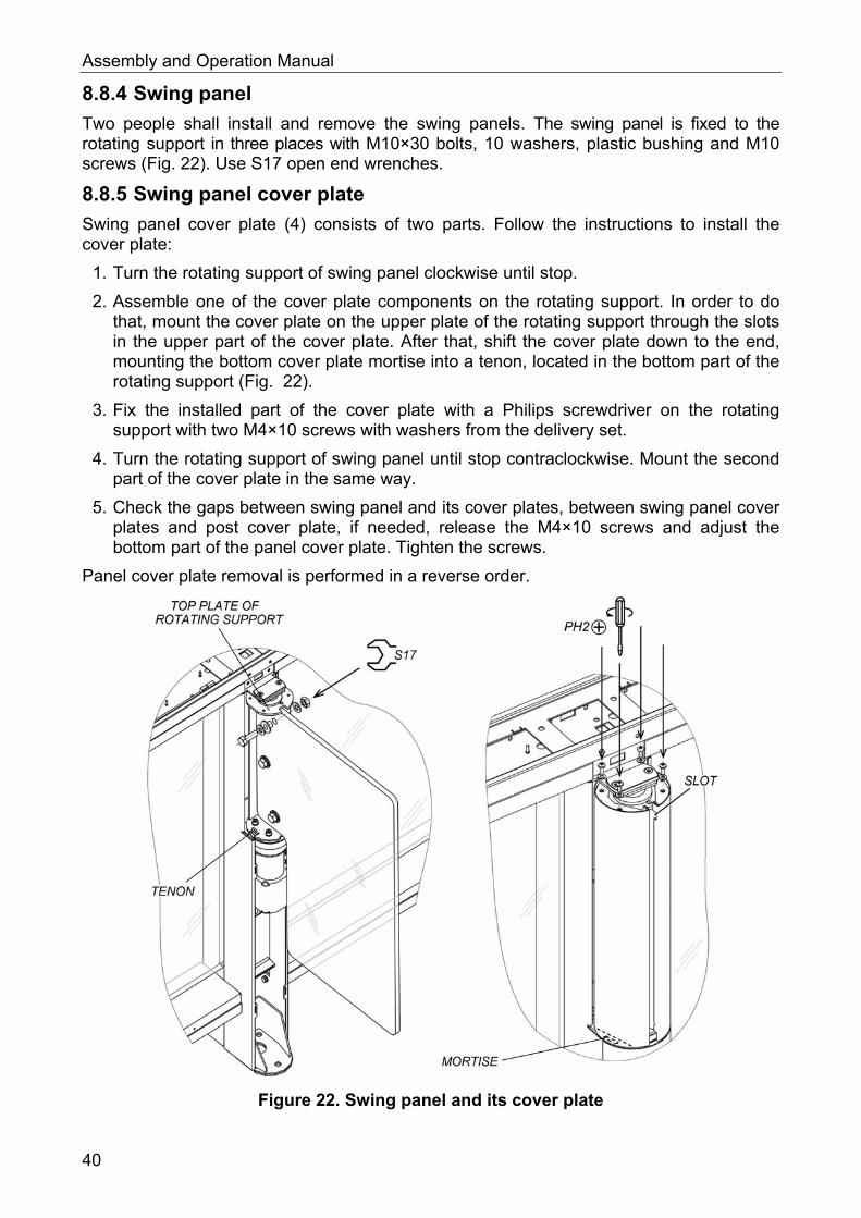
8.8.4 Swing panel
Two people shall install and remove the swing panels. The swing panel is fixed to the rotating support in three places with M10×30 bolts, 10 washers, plastic bushing and M10 screws (Fig. 22). Use S17 open end wrenches.
8.8.5 Swing panel cover plate
Swing panel cover plate (4) consists of two parts. Follow the instructions to install the cover plate:
1. Turn the rotating support of swing panel clockwise until stop.
2. Assemble one of the cover plate components on the rotating support. In order to do that, mount the cover plate on the upper plate of the rotating support through the slots in the upper part of the cover plate. After that, shift the cover plate down to the end, mounting the bottom cover plate mortise into a tenon, located in the bottom part of the rotating support (Fig. 22).
3. Fix the installed part of the cover plate with a Philips screwdriver on the rotating support with two M4×10 screws with washers from the delivery set.
4. Turn the rotating support of swing panel until stop contraclockwise. Mount the second part of the cover plate in the same way.
5. Check the gaps between swing panel and its cover plates, between swing panel cover plates and post cover plate, if needed, release the M4×10 screws and adjust the bottom part of the panel cover plate. Tighten the screws.
Panel cover plate removal is performed in a reverse order.
Figure 22. Swing panel and its cover plate
40
ST-01 Speed Gate, STD-01 Double-Sided Section
8.8.6 Central post indication module
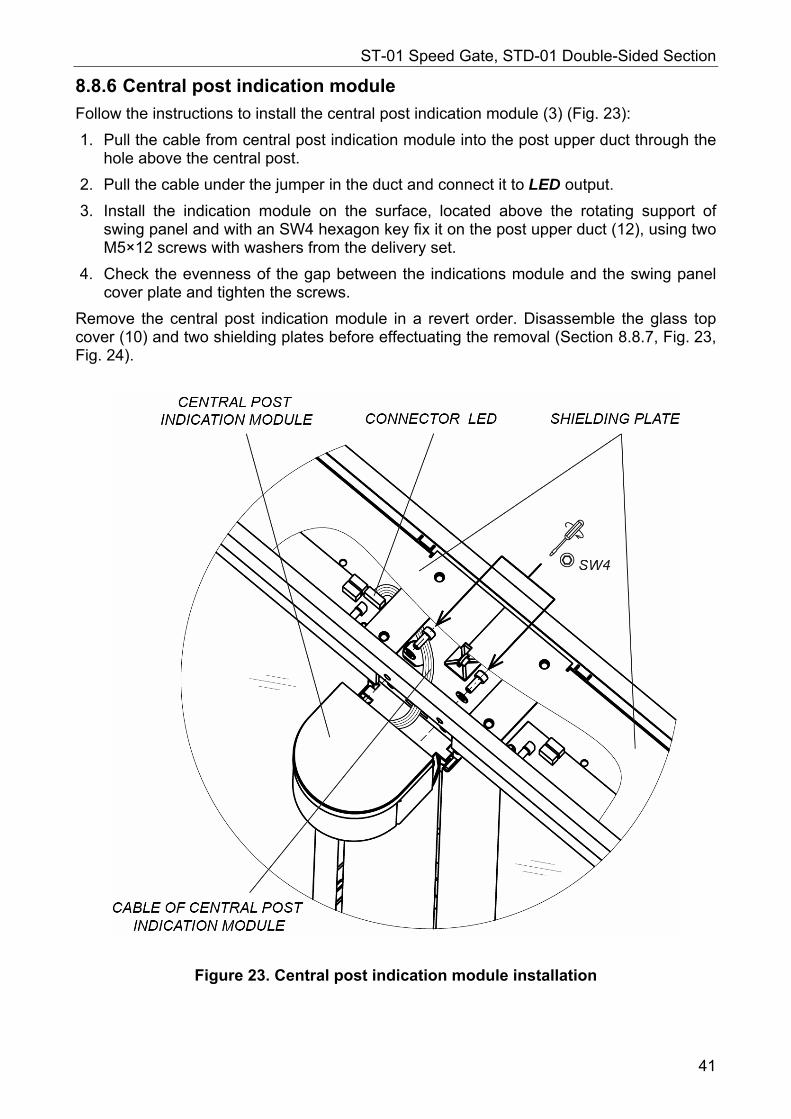
Follow the instructions to install the central post indication module (3) (Fig. 23):
1. Pull the cable from central post indication module into the post upper duct through the hole above the central post.
2. Pull the cable under the jumper in the duct and connect it to LED output.
3. Install the indication module on the surface, located above the rotating support of swing panel and with an SW4 hexagon key fix it on the post upper duct (12), using two M5×12 screws with washers from the delivery set.
4. Check the evenness of the gap between the indications module and the swing panel cover plate and tighten the screws.
Remove the central post indication module in a revert order. Disassemble the glass top cover (10) and two shielding plates before effectuating the removal (Section 8.8.7, Fig. 23, Fig. 24).
Figure 23. Central post indication module installation
41
Assembly and Operation Manual
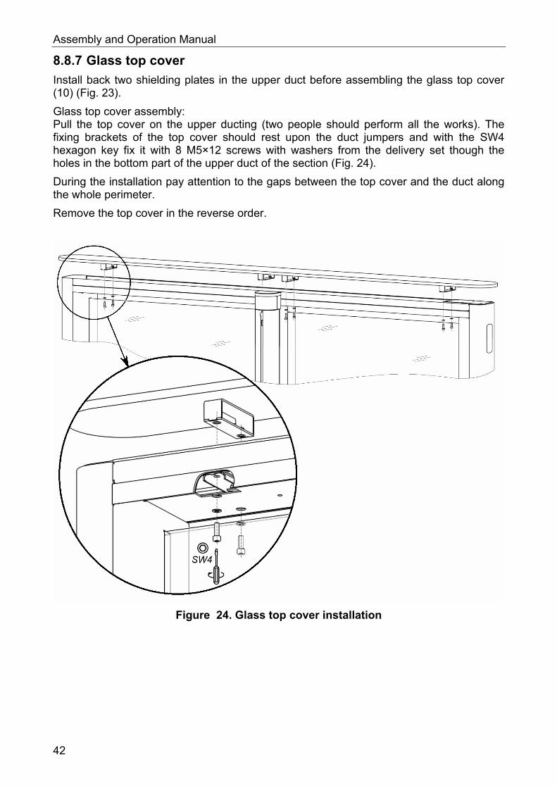
8.8.7 Glass top cover
Install back two shielding plates in the upper duct before assembling the glass top cover (10) (Fig. 23).
Glass top cover assembly: Pull the top cover on the upper ducting (two people should perform all the works). The fixing brackets of the top cover should rest upon the duct jumpers and with the SW4 hexagon key fix it with 8 M5×12 screws with washers from the delivery set though the holes in the bottom part of the upper duct of the section (Fig. 24).
During the installation pay attention to the gaps between the top cover and the duct along the whole perimeter.
Remove the top cover in the reverse order.
Figure 24. Glass top cover installation
42
ST-01 Speed Gate, STD-01 Double-Sided Section
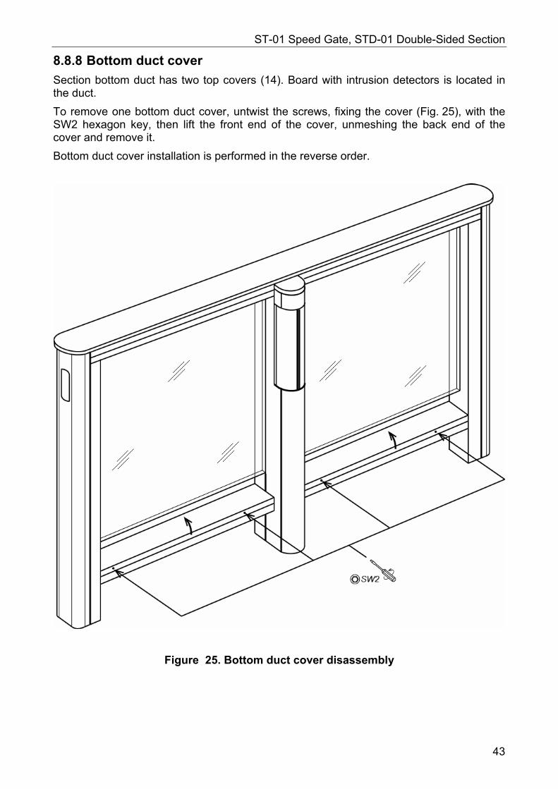
8.8.8 Bottom duct cover
Section bottom duct has two top covers (14). Board with intrusion detectors is located in the duct.
To remove one bottom duct cover, untwist the screws, fixing the cover (Fig. 25), with the SW2 hexagon key, then lift the front end of the cover, unmeshing the back end of the cover and remove it.
Bottom duct cover installation is performed in the reverse order.
Figure 25. Bottom duct cover disassembly
43
Assembly and Operation Manual
8.8.9 Filling glass
Attention! Be careful during the filling glass replacement, prevent it from falling and do not hit it against the metallic elements of the section. Two people should perform all the works.
Follow this order to replace the filling glass of the section (13):
1. Remove the section top cover (10) (Section 8.8.7).
2. Remove the indication module of the central post (3) (Section 8.8.6).
3. Remove the swing panel cover plate (4) (Section 8.8.5).
4. Remove the central post cover plate (5) (Section 8.8.1).
5. Remove both covers from the bottom duct (14) (Section 8.8.8).
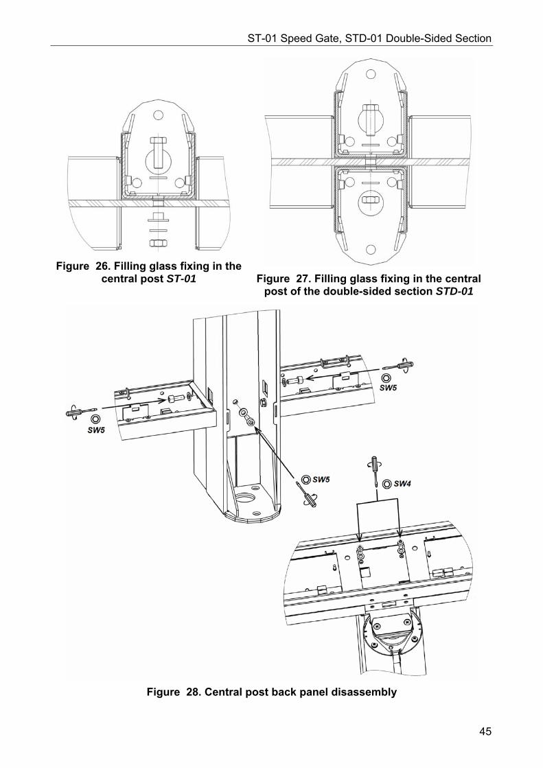
6. For ST-01 section: remove the central post back panel (6). Untwist 2 M6×16 screws (for SW5 hexagon) in the bottom ducts, M6×16 screws (for SW5 hexagon) at the bottom of the central post and 2 M5×12 screws (for SW4 hexagon) in the top duct (Fig. 28).
For STD-01 section: follow the instructions described in par. 2-4 for the second side of the section.
7. Remove the front panels (8) from both posts.
8. Using S17 open-end and hexagon keys, untwist and remove 6 M10×30 screws with washers, plastic bushing and screws fixing the filling glass (two in the mounting arms of the side posts and two in the central post) (Fig. 26, 27).
9. Pull the filling glass into one side from one side post until its other side gets out of the second side post. Keep the glass from falling when performing the removal!
10. Shift the free end of the glass aside and take out the second end of the glass from the side section. The glass is disassembled.
11. Install the new filling glass in the reverse order.
44
ST-01 Speed Gate, STD-01 Double-Sided Section
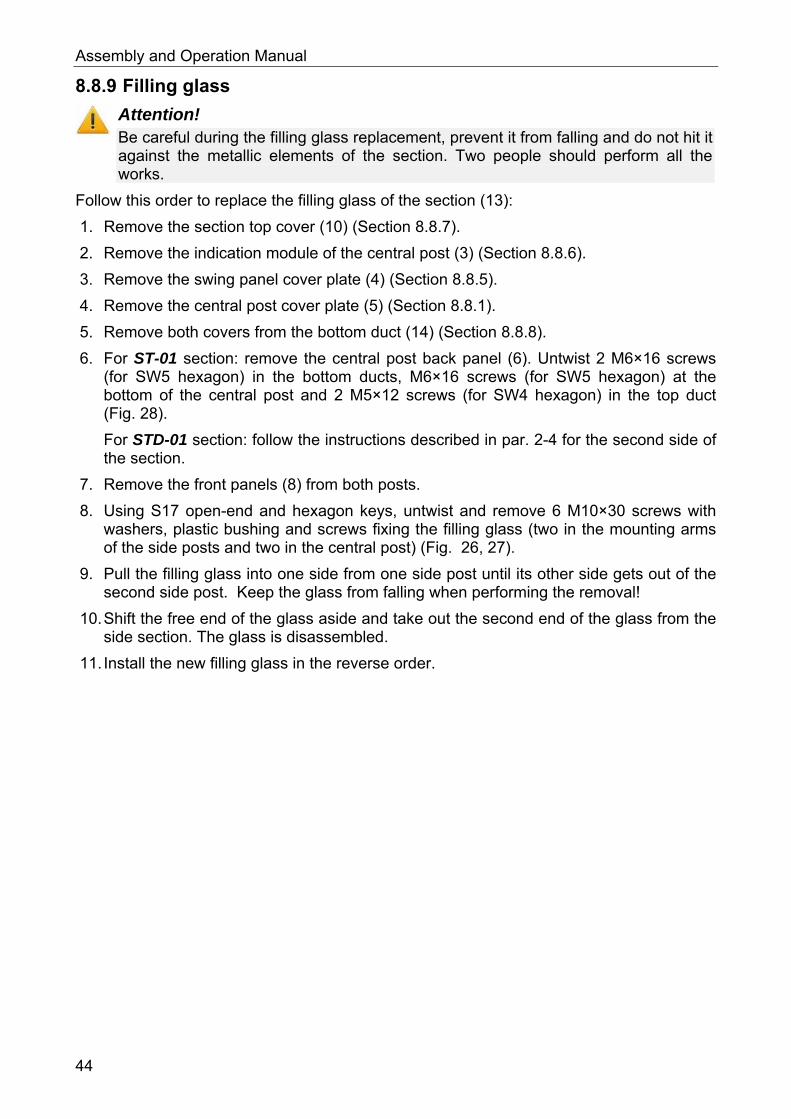
Figure 26. Filling glass fixing in the central post ST-01
Figure 27. Filling glass fixing in the central post of the double-sided section STD-01
Figure 28. Central post back panel disassembly
45
Assembly and Operation Manual
9 OPERATION Follow the instructions of speed gate operation in accordance with Section 7.2.
Attention! Do not move through the speed gate passage area any objects with dimensions
exceeding the width of the passageway. Do not jerk and hit any elements of the speed gate to prevent their mechanical
deformation. Do not dismantle or adjust mechanisms, ensuring the speed gate operation. Do not use substances that may cause mechanical damage or corrosion of the
surface for speed gate cleaning.
9.1 Power-up
Attention! Before speed gate power-up make sure that the passage zone is free and nothing interferes with the swing panel movement.
Follow this sequence during speed gate power-up: 1. Connect the speed gate power supply unit to the AC outlet with the voltage and
frequency rating complying with the certificate for the power supply unit. 2. Switch on the speed gate power supply unit. Speed gate swing panels get
automatically set into an initial (locked) position. 3. At pulse control mode the «Passage denial» command is sent automatically, at the
potential control mode – «Always locked» command is sent automatically (Tables 6 and 7). Speed gate swing panels block the passage zone. The speed gate is ready for operation.
9.2 Pulse control mode Speed gate control command sending from the RC panel and its indication on the speed gate sections is performed in accordance with Table 6. Passage directions are independent of each other, i.e. sending a command for one direction, doesn’t change the opposite direction mode.
Table 6. Pulse control mode
Indication Command
RC panel operator actions12 RC panel Central post
Speed gate state
«Passage denial»
Press the STOP button
Red «Stop» indicator is on
Red for both directions
The swing panels are closed
«Single passage in a set direction»
Press the LEFT/ RIGHT buttons
Red «Stop» indicator is on and the green indicator for the set direction «Left»/ «Right» is on
Green for the set direction
The swing panels turn in the passage direction
«Free passage in a set direction»
Press both STOP and LEFT/ RIGHT buttons simultaneously.
Green indicator of the set direction «Left»/ «Right» is on
Green for the set direction
The swing panels are open in the free passage direction until sending the next command
12 Speed gate control from the WRC is the same as the control from the RC panel. Buttons on the
WRC fob control the same functions as the RC panel buttons.
46
ST-01 Speed Gate, STD-01 Double-Sided Section
Indication Command
RC panel operator actions12 RC panel
Speed gate state Central post
«Free passage»
Press all three LEFT, STOP and RIGHT buttons simultaneously
Both green indicators «Left» and «Right» are on
Green for both directions
Swing panels are open until sending the next command
RC panel buttons and indicators are shown in Figure 7. After setting «Single passage in a set direction» command speed gate swing panels
get closed automatically after Holding in unlocked state (8 seconds as initial settings) expiration, if the command has not been resent.
After sending «Single passage in a set direction» command, the «Free passage» command or «Passage denial» command can be sent.
After sending «Free passage in a set direction» command, only «Passage denial» command can be sent.
9.3 Potential control mode Speed gate control command sending and its indication are performed according to Table 7. Passage directions are independent of each other, i.e. sending a command for one direction doesn’t change the opposite passage direction.
Table 7. Potential control mode
Indication Command Required to ensure
RC panel Central post Speed gate state
«Close both directions»
High level on Unlock A and Unlock B contacts (or low level on Stop contact)
Red «Stop» indicator is on
Red for both directions
Swing panels are closed
«Direction open»
Low level on the contact of the chosen direction. High level on all other contacts
Green indicator of the chosen «Left» / «Right» direction is on
Green for the chosen direction
Swing panels turn in the passage direction
«Both directions open»
Low level on Unlock A and Unlock B contacts. High level on Stop contact
Both green «Left» and «Right» indicators are on
Green for both directions
Swing panels are open until sending the new command
9.4 In case of an emergency In case something interferes with the free turn of the swing panels, the speed gate automatically switches into «Emergency» mode. This mode is required to avoid motor drive failure, caused by overheating.
If there’s an obstacle, interfering with the swing gate turn in the set direction, three turns in the same direction with a 3 seconds interval are made. If the obstacle is not removed, the speed gate turns to «Emergency» mode. In «Emergency» mode speed gate swing panels can turn freely to a ±90º angle, which allows easy obstacle removing from the passage zone. In this case all three light indicators of the RC panel switch on and there’s a sound indication of 3 short sound signals, 20 seconds each.
«Emergency» mode is switched off automatically after an obstacle is removed, the speed gate passage zone is vacated and the swing panels are set into an initial (closed) position.
47

Assembly and Operation Manual
10 MAINTENANCE Technical maintenance is to be performed by qualified specialists after careful study of this Manual.
Use liquid nonabrasive cleaners, containing aqua ammonia to remove the contaminations of the speed gate sections and swing panels.
48
ST-01 Speed Gate, STD-01 Double-Sided Section
11 TRANSPORTATION AND STORAGE Speed gate storage is allowed in dry indoor facilities at an ambient air temperature from -40°C to +45°C at relative air humidity 80% at +15°C.
Speed gate in the original package should be transported in closed freight containers or others closed type cargo transport units.
Do not stack the boxes with the speed gates during transportation and storage.
After transportation or storage at temperatures below zero or at high air humidity, prior to installation the speed gate must be kept in the original package for no less than 24 hours indoors at room temperatures.
49
Assembly and Operation Manual
Appendix 1. Operation algorithm at pulse control mode
«Passage denial» (locked for entry and exit) – active front at the Stop contact while there is a high level at the Unlock A and Unlock B contacts. Both passage directions are locked at this command.
«Single passage in A direction» (open for passage of one person in A direction) – active front at “Unlock A” contact, while there is a high level at “Stop” and “Unlock B” contact. At this command the passage direction A opens either for 5 sec. or until the passage has been made in this direction or until the command “Passage denial”, and the status of the passage direction B does not change at that. The command is ignored if at the moment of its receipt the status of the passage direction A is “Always free”.
«Single passage in B direction» (open for passage of one person in B direction) – active front at the contact “Unlock B” while there is a high level at the contacts “Stop” and “Unlock A”. At this command the passage direction B opens either for 5 sec. or until the passage has been effected in this direction or until the command “Always locked”, and the status of the passage direction A does not change. The command is ignored if at the moment of its receipt the status of passage direction B is “Free passage”.
«Free passage in A direction» (open for free passage in A direction) – active front at the contact “Unlock A” while there is a low level at the contact “Stop” and a high level at the contact “Unlock B”, or active front is at the contact “Stop” while there is a low level at the contact “Unlock A” and a high level at the contact “Unlock B”. At this command the passage direction A opens until the command “Passage denial” is received; the status of the passage direction B does not change at that.
«Free passage in B direction » (open for free passage in B direction) – Active front is at the contact “Unlock B” while there is a low level at the contact “Stop” and a high level at the contact “Unlock A”, or active front is at the contact “Stop” while there is a low level at the contact “Unlock B” and a high level at contact “Unlock A”. At this command the passage direction B opens until the command “Passage denial” is received; the status of the passage direction A does not change at that.
«Free passage» (open for free passage in both directions) – Active front is at the contact “Unlock A” while there is a low level at the contacts “Unlock B” and “Stop”, or active front is at the contact “Unlock B” while there is a low level at the contacts “Unlock A” and “Stop”, or active front is at the contact “Stop” while there is a low level at the contacts “Unlock A” and “Unlock B”. Both directions open at this command until the command “Passage denial” is received.
50
ST-01 Speed Gate, STD-01 Double-Sided Section
51
Appendix 2. Operation algorithm at potential control mode
«Both directions are locked» (locked for entry and exit). There is a high level at the contacts “Unlock A” and “Unlock B” or a low level at the contact “Stop”. Both passage directions lock at this command.
«A direction is open» (open for passage in A direction). There is a low level at the contact “Unlock A” while a high level is present at the contacts “Stop” and “Unlock B”. At this command the direction A opens till the low-level signal removal from the contact A or until the command “Both directions locked” is received. The status of the direction B does not change at that.
«B direction is open» (open for passage in B direction). There is a low level at the contact “Unlock B” while there is a high level at the contacts “Stop” and “Unlock A”. At this command the direction B opens till the low-level signal removal from the contact B or until the command “Both directions locked” is received. The status of the direction A does not change at that.
«Both directions are open» (open for entry and exit in both directions). There is a low level at the contacts “Unlock A” and “Unlock B” while there is a high level at the contact “Stop”. Both directions open at this command till the low-level signal removal from one of the contacts A (B) or until the command “Both directions locked” is received.

PERCo
Polytechnicheskaya str., 4, block 2 194021, Saint Petersburg
Russia
Tel: +7 812 247 04 64
E-mail: [email protected] [email protected]
www.perco.com

www.perco.com