downflow, upflow electric furnaces owners manual ...batchelorsupply.com/data/nordyne/903588d...
TRANSCRIPT
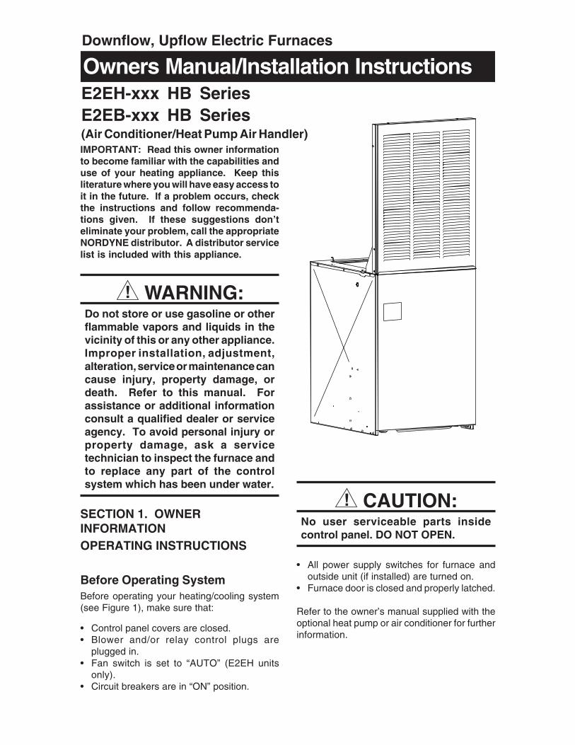
IMPORTANT: Read this owner informationto become familiar with the capabilities anduse of your heating appliance. Keep thisliterature where you will have easy access toit in the future. If a problem occurs, checkthe instructions and follow recommenda-tions given. If these suggestions don’teliminate your problem, call the appropriateNORDYNE distributor. A distributor servicelist is included with this appliance.
! WARNING:Do not store or use gasoline or otherflammable vapors and liquids in thevicinity of this or any other appliance.Improper installation, adjustment,alteration, service or maintenance cancause injury, property damage, ordeath. Refer to this manual. Forassistance or additional informationconsult a qualified dealer or serviceagency. To avoid personal injury orproperty damage, ask a servicetechnician to inspect the furnace andto replace any part of the controlsystem which has been under water.
SECTION 1. OWNERINFORMATIONOPERATING INSTRUCTIONS
Before Operating SystemBefore operating your heating/cooling system(see Figure 1), make sure that:
• Control panel covers are closed.• Blower and/or relay control plugs are
plugged in.• Fan switch is set to “AUTO” (E2EH units
only).• Circuit breakers are in “ON” position.
! CAUTION:No user serviceable parts insidecontrol panel. DO NOT OPEN.
• All power supply switches for furnace andoutside unit (if installed) are turned on.
• Furnace door is closed and properly latched.
Refer to the owner’s manual supplied with theoptional heat pump or air conditioner for furtherinformation.
Owners Manual/Installation InstructionsE2EH-xxx HB SeriesE2EB-xxx HB Series(Air Conditioner/Heat Pump Air Handler)
Downflow, Upflow Electric Furnaces

2
Indoor Coil(optional)
Coil Air Filters(used with indoor coil)
Blower Selector Switch (EH only)
Furnace Air Filter(NOT used with
coil air filters)
Control PanelCover (left)
Data Label
Circuit Breakers
Control Panel Cover (right)
A/C or H/PRelay Box(optional)
Blower
Figure 1. Furnace Parts Identification
Model Identification
10 20 30
50 60 70 80 90
SYSTEM
HEAT OFF COOL
VENTILATE
ON AUTO
Temperature Selector
Temperature Scales
System Switch(optional sub-base)
Fan Switch(optional sub-base)
E 2 EB - 010 HB
Product TypeE - Electric Furnace
Generation2 - Second Series
Product IdentifierEH - Heat Only
EB - A/C Blower Equipped
ModelRevision(R=replacement)
Electrical CodeH - 240-1-60
Primary Capacity010 - 10 kw 012 - 12 kw015 - 15 kw 017 - 17 kw020 - 20 kw 023 - 23 kw

3
! CAUTION:For optional A/C or H/P systems,always wait at least five minutes afterthe system shuts off before restartingthe system. Observe this procedurewhen operating the system per thefollowing instructions.
To Operate System in CoolingModeNOTE: The “FAN ON/FAN AUTO” (fan switch)and “HEAT/OFF/COOL” (system switch) arelocated either on your thermostat (if it’s suppliedwith a sub-base) or on the relay box added toyour furnace.
1. Make sure blower selector switch is on“Auto.”
2. Set fan switch to “AUTO.”3. Set system switch to “COOL.”4. Set thermostat temperature selector to
desired comfort level.
To Operate System in HeatingMode1. Make sure blower selector switch is on
“Auto.”2. Set fan switch to “AUTO.”3. Set system switch to “HEAT.”4. Set thermostat temperature selector switch
to desired comfort level.
NOTE: Allow at least one hour for the roomtemperature to stabilize before you make asecond adjustment to the thermostat setting.Once the desired comfort level is established,make only small adjustments to the thermostatsetting to meet changing temperature condi-tions.
To Operate Blower Continuously1. Set blower selector switch to “ON” for sum-
mer air circulation only (see Figure 1),OR...
2. If thermostat is equipped with optional heat-ing/cooling sub-base or relay box (seeFigure 1), set fan switch to “ON.”
To Balance Air Distribution1. On a typical day, set thermostat selector to
desired comfort level and operate system
for several hours with all air registers open.2. With system on, check temperature in all
rooms.3. Partially close registers in rooms that are
too warm (in heating mode) or too cool (incooling mode) and in rooms that are infre-quently occupied.
4. Re-check room temperature and adjustregisters as needed.
To Shut Off System1. Make sure blower selector switch is on
“Auto”.2. Set thermostat temperature selector to low-
est temperature setting, OR...3. For thermostats with optional sub-base (see
Figure 1), or for systems with relay box, setsystem switch to “OFF.”
! WARNING:To prevent hazard of electrical shockand injury from moving parts, becertain the thermostat is off and thefurnace circuit breaker(s) are in the“OFF” position before servicing. Closeand properly latch the outer door afterdoing the following recommendedmaintenance.
MAINTENANCE INSTRUCTIONSRegularlyNOTE: If a coil is installed, furnace filter is notused.1. Replace furnace air filter (see Figure 1),
OR...2. Remove coil filters, wash, and allow to dry.
Re-install coil filters to original positions.3. Vacuum or wipe clean interior of furnace
cabinet.4. Clean all lint and dust from around furnace.
Every Six Months1. Vacuum or wipe away any dust or lint on
blower motor.
Before Each Heating SeasonNOTE: If a coil is installed, furnace filter is notused.1. Replace furnace air filter (see Figure 1),
OR...2. Remove coil filters, wash, and allow to dry.
Re-install coil filters to original positions.

4
3. Have a qualified serviceman inspect allfurnace components and field wiring andclean and service heating system asneeded. If this furnace was installed withaluminum power supply wiring, have ser-viceman periodically check all connectionsto prevent possible equipment failure and/or fire hazard. Do not attempt any servicefunction yourself which requires openingfurnace control panel covers.
BEFORE YOU CALL A SERVICEMAN1. Make sure thermostat temperature selec-
tor is set above room temperature for heat-ing or below room temperature for cooling.If thermostat is equipped with heating/cool-ing sub-base, make sure system switch(see Figure 1) is set to “HEAT” for furnaceoperation or set to “COOL” for optional air-conditioning operation.
2. Check main household service panel tosee if appropriate circuit disconnect(s) forappliance power supply is on.
3. Refer to instructions under Before Operat-ing System for pre-operation checks.
4. Refer to instructions under Before EachHeating Season for maintenance proce-dures and recommended service checks.
5. Refer to owner’s manual provided withoptional air conditioner or heat pump (ifinstalled) for service and maintenance.
NOTE: All servicing of this heating applianceother than the normal maintenance described inthis section must be done by authorized trainedservice personnel. Do not open the controlpanels (see Figure 1) at any time.
Please specify the complete model and serialnumbers shown on the furnace data label (seeFigure 1) for all warranty service and whenordering replacement parts or optional equip-ment. Refer to the replacement parts list pro-vided with the furnace for part numbers.
OPTIONAL AIR CONDITIONERAND HEAT PUMPYour E2 Series electric furnace is approved foruse with an optional central air conditioner or aheat pump. To adapt this heating appliance toa “total comfort system,” contact your nearestNORDYNE distributor.
Optional air conditioners and heat pumps arelisted by Underwriters’ Laboratories (UL) orEnvironmental Testing Laboratories (ETL) andcertified by ARI and the Canadian StandardsAssociation (CSA), or Warnock Hersey or ETLC.These cooling systems include energy-savingcomponents to provide maximum cooling per-formance at electrical energy usage levels es-tablished by federal standards. Refer to theoperation instruction label on your furnace forthe optional air conditioning equipment approvedfor your heating appliance.
SECTION 2.INSTALLER INFORMATION
GENERALThese instructions and specifications are pri-marily intended to assist qualified individualsexperienced in the proper installation of homeheating and air conditioning appliances. Somelocal codes require licensed personnel for theinstallation and service of this type of equip-ment. Approved installation, operation, andmaintenance of this central heating systemappliance must be in accordance with the listedspecifications contained in these instructionsand other documents supplied with the furnaceand/or optional air conditioning equipment. Referto local authorities having jurisdiction for furtherinformation.
Before beginning installation, read these in-structions thoroughly. Follow all warnings andcautions in the instructions and on the unit.
Improper installation, service adjustment, ormaintenance can cause explosion, fire, electri-cal shock or other conditions which may result inpersonal injury or property damage. Unlessotherwise noted in these instructions, use onlyfactory-authorized kits and accessories whenmodifying this product.
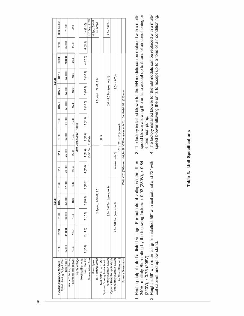
Overview of E2 FurnaceE2E(-) Series electric furnaces are available intwo models. E2EH models are equipped withthe standard two-speed blower. E2EH modelscan be easily converted for use with NORDYNEsplit-system air conditioners and heat pumps.E2EB models are air-conditioning ready; that is,they are equipped with a multi-speed (four-speed) blower, blower relay, and cabinet insu-lation kit. See Table 3 for cooling and heat pumpavailability with factory installed blower.

5
For typical non-ducted return air downflowapplications, an air-conditioner or heat-pumpcoil can be installed by mounting the coil directlyon top of the furnace without adding sheet metalcavities or cutting and trimming wood panels.
A return air grille for closet or alcove installationsis available. For downflow alcove installations,the grille (with frame provided) may be attachedto the top of the furnace and all paneling and trimflushed to it. This installation provides an ac-cess door for future installation of NORDYNEair conditioning or heat pump coils on top of thefurnace.
Power entrance for all models may be throughthe right side or through the bottom of the unit(when viewing the unit in a downflow position).
UNIT CHECKOUTBefore installing this furnace:1. Inspect unit for possible shipping damage.
If shipping damage is found, file claim withtransportation company.
2. Record furnace model number and serialnumber (see furnace data label) for futurereference.
3. Carefully read all instructions supplied withoptional equipment to be installed withfurnace.
CODES, SPECIFICATIONS, ANDREQUIREMENTS
Furnace CodesInstallation and wiring of this furnace, as well asthe design and construction of the home ductsystem, must be in accordance with one or moreof the following codes:• HUD MANUFACTURED HOME CON-
STRUCTION AND SAFETY STANDARD(Title 24, Part 3280)
• American National Standards (ANSI)A119.11, C1-NFPA 7 (National ElectricalCode)
• CANADIAN STANDARDS (C.S.A.) Z240.6.1,and Z240.9.1.
Table 1. Miscellaneous Listings & Installation Requirements
Listing agency(s)May vary by model, check the unit data label for applicable agency listing mark.
Approved Installation Configurations
Approved for: single/multistory residential or mobile/modular/manufactured structures. Upflow, downflow, (freestanding/closet/alcove)
Accessibility for Servicing Minimum of 18" (46 cm) required in front of unit.Minimum Clearance to Combustibles
0" from all surfaces of furnace cabinet, ducts, optional coil housing and plenum connector. No separate subbase required for installations on combustible flooring.
Minimum return air 200 in.2 (1290 cm2) heating only* opening required (total free area) 235 in2 (1516 cm2) A/C or H/P up to 4-ton installed.*
390 in.2 (2516 cm2) A/C or H/P up to 5 ton installed.*or return air grille and frame assembly p/n 902989 or wall mount grille p/n 902999.
Return air grilleUse return air grille and frame assembly P/N 902989- or equivalent for alcove installation.
(closet or alcove installation)Use wall mount return air grilled P/N 902999- or equivalent for closet installation.155 in.2 (1000 cm2) must be added for5-ton A/C or H/P system.
250 in2 (1613) cm2 A/C or H/P up to 4 ton w/1" clearance installed.
6
All local codes having jurisdiction shall alsoapply.
Air Duct Codes and SpecificationsAir ducts must be installed in accordance withNational Fire Protection Association standardsNFPA 90A and NFPA 90B, these instructions,and all applicable local codes.• Materials: Air ducts must be aluminum, tin
plate, galvanized sheet steel, or other ap-proved materials for outlet or return air ducts.
• Construction: Snap-Lock or Pittsburgh-Lockseams are preferred. All other types ofseams must be made tight to prevent leak-age.
• Sizing: Supply duct system must be designedfor proper air distribution. Static pressuremeasured externally to furnace shall not ex-ceed static pressure rating listed on furnacenameplate.
• Location of Openings: Duct system must bedesigned so that no supply registers arelocated in duct system directly below furnace.
Return Air Codes andRequirementsNon-ducted return air systems may be used forcloset or alcove installations.
NOTE: Applicable installation codes may limitthe furnace to installation in a single-story resi-dence only. Furnace installations other thancloset or alcove installations require ductedreturn air systems.
Air return to the furnace must have a minimumfree area opening (see Table 1).
Acceptable floor or ceiling return air systems forcloset installations with return air enteringthrough an opening in the closet floor or ceilingmust meet all of the following requirements:• Return air opening into closet, regardless of
its location, must not be smaller than sizespecified on unit data label.
• If located in floor of closet, return air openingmust be provided with means of preventingits inadvertent closure by a flat object placedover opening.
• Materials located in return air duct systemmust have a flame-spread classification of200 or less.
• Noncombustible pans having 1" upturnedflanges must be located beneath openings ina floor-return duct system.
• Wiring materials located in return duct sys-tem must conform to NEC Article 300-22(c).
• Gas piping must not run in or through returnair duct system.
• If return air opening is located below top offurnace, a minimum clearance must be pro-vided between opening and furnace (see“Accessibility for servicing” in Table 1).
Closed-Off Space RequirementsLiving space not served by, and closed off from,the return air ducts to the furnace by doors,sliding partitions, and other means must beprovided with permanent, uncloseable open-ings in the doors or partitions to allow air toreturn to the furnace from all parts of the home.Return air grilles, with a minimum open area ofone square inch for every five square feet ofliving space closed off from the furnace, must beprovided in the door or room partition.
OPTIONAL EQUIPMENTContact your nearest NORDYNE distributor fora complete list of electric furnace accessories.
Return Air GrilleA return air grille and frame assembly (seeFigure 2) is available for use in non-ductedreturn air installations. In downflow alcove in-stallations, the grille and frame assembly maybe mounted directly to the top of the furnace. Incloset installations, a wall mount grille is avail-able for attachment to a door or wall.
Optional Automatic FurnaceDamper #901083 -Furnace may (not required) be equipped withthe optional automatic damper when a pack-aged air conditioner is installed and connectedto the warm air duct system. This damper pre-vents cooled air from discharging through thefurnace cabinet, causing excessive cooling ofthe immediate area. Refer to instructions sup-plied with the damper for details.
Multi-Speed Blower ConversionPackage (4 or 5 ton):Upgrade blower packages are available foradding air conditioning or heat pump systems.See furnace “Options and Compatibility” labelfor systems available.

7
Table 2. Optional Air Conditioning andHeat Pump Equipment
Figure 3. Optional Rear Mounting Plate(P/N 389080)
3"(76 mm)
20-1/8"(511 mm)
11/16"(17 mm)
Notes:1) For A/C and H/P use.2) Includes coil filters.3) For upflow or downflow installations.4) For upflow A/C or H/P installations (includes
one filter; use filter from furnace tocomplete filtering system in this accessory).
5) Standard in EB models.
Upflow Stand
Filters (one obtained from furnace)
23 3/4" (603 mm)
20" (508 mm)
14" (357 mm)
20" (508 mm)Cabinet
Insulation
Upflow Coil Cabinet
23 3/4" (603 mm)
29"(737 mm)
NOTE: See Table 2 for descriptionsand notes
Figure 2. Optional Accessories
1
2
3
4
7
8
27"(686 mm)
29"(737 mm)
20"(508 mm)
23 3/4"(603 mm)
ItemNumber
(See Fig.) Description1 4-Speed Blower
4 Ton - See Notes: 1 & 55 Ton - See Note: 1
2 A.C./H.P. Relay Control See Note: 1
3 Cabinet Insulation KitSee Notes: 1 & 5
4 "A"-Coil Conversion KitSee Note: 2
5 Coil CabinetSee Note: 3
6 Upflow StandSee Note: 4
7 A/C and H/P Indoor Coils8 Return Air Grille and
Frame Assembly
8
Tab
le 3
. U
nit
Sp
ecif
icat
ion
s
1.H
eatin
g ou
tput
rat
ed a
t lis
ted
volta
ge.
For
out
puts
at
volta
ges
othe
r th
an24
0V,
mul
tiply
Btu
h ra
ting
by t
he f
ollo
win
g fa
ctor
s: x
0.9
2 (2
30V
), x
0.8
4(2
20V
), x
0.7
5 (2
08V
)2.
Hei
ght i
s 56
" with
retu
rn a
ir gr
ille
inst
alle
d, 5
8" w
ith c
oil c
abin
et a
nd 7
2" w
ithco
il ca
bine
t and
upf
low
sta
nd.
3.T
he fa
ctor
y in
stal
led
blow
er fo
r the
EH
mod
els
can
be re
plac
ed w
ith a
mul
ti-sp
eed
blow
er a
llow
ing
the
units
to a
ccep
t up
to 5
tons
of a
ir co
nditi
onin
g or
4 to
ns h
eat
pum
p.4.
The
fact
ory
inst
alle
d bl
ower
for t
he E
B m
odel
s ca
n be
repl
aced
with
a m
ulti-
spee
d bl
ower
allo
win
g th
e un
its t
o ac
cept
up
to 5
ton
s of
air
cond
ition
ing.
E2E
HE
2EB
010H
012H
015H
015H
R01
7H02
0H02
3H01
0H01
2H01
5H01
5HR
017H
020H
Rat
ed H
eatin
g O
utp
ut, B
tuh
(see
not
e 1)
35,0
0041
,000
53,0
0057
,000
57,0
0070
,000
75,0
0035
,000
41,0
0053
,000
57,0
0057
,000
70,0
00W
atts
(Tot
al k
w, H
eatin
g E
lem
ents
and
Blo
wer
)10
.412
.015
.416
.616
.620
.422
.010
.412
.015
.416
.616
.620
.4
Sup
ply
Vol
tage
Hea
ting
Ele
men
ts,
No.
(Tot
al k
w)
2 (1
0.0)
2 (1
1.6)
2 (1
5.0)
3 (1
6.2)
3 (1
6.2)
4 (2
0.0)
4 (2
1.6)
2 (1
0.0)
2 (1
1.6)
2 (1
5.0)
3 (1
6.2)
3 (1
6.2)
4 (2
0.0)
Blo
wer
Whe
el S
ize
10.5
" D
ia.,
8" W
ide
Mot
or S
pee
d,
H.P
. Rat
ing,
Am
ps
Test
ES
P, i
n. w
.c. M
ax0.
3O
ptio
nal C
oolin
g A
vaila
ble
with
fa
ctor
y in
stal
led
blo
wer
Op
tiona
l Hea
t P
ump
Ava
ilab
le
with
fact
ory
inst
alle
d b
low
er2.
0 -
3.0
Ton
(see
not
e 3)
n/a
(see
not
e 3)
Air
Filte
r (S
tand
ard
)16
" x
20"
x 1"
(nom
inal
)
Furn
ace
Dim
ensi
ons
Wid
th-2
0" (5
08m
m),
Hei
ght-
29"
(737
mm
) (se
e no
te 2
), D
epth
-24
1/2"
(623
mm
)
2.0
- 4.
0 To
n
Ele
ctri
c Fu
rnac
e M
od
els
2 S
pee
d, 1
/5 H
P, 2
.04
Sp
eed
, 1/3
HP
, 2.9
2.0
- 3.
0 To
n (s
ee n
ote
3)2.
0 -
4.0
Ton
(see
not
e 4)
240
Vol
ts/6
0Hz/
1-P
hase
023H
023H
5-T
on
75,0
0075
,000
22.0
22.0
4 (2
1.6)
4 (2
1.6)
11"
Dia
., 8"
W
4 S
pd
, 3/4
HP
3.
8 A
mp
s
2.0
- 5.
0 To
n
9
AB
19”(483 mm)
19"
(483
mm
)
TOP VIEW
X
Reducer
*Felt Seal
Corner Spacers
C
*OPENING TO DUCTA= 13-1/4" (337 mm)B= 10-3/4" (274 mm)WITH PLATE (C) REMOVEDOPENING BECOMES13-1/4” x 13-1/4”
*Indicates only applicable for Finger Tab Duct Connector
x
SUPPLY AIR DUCT
FLOOR CAVITY
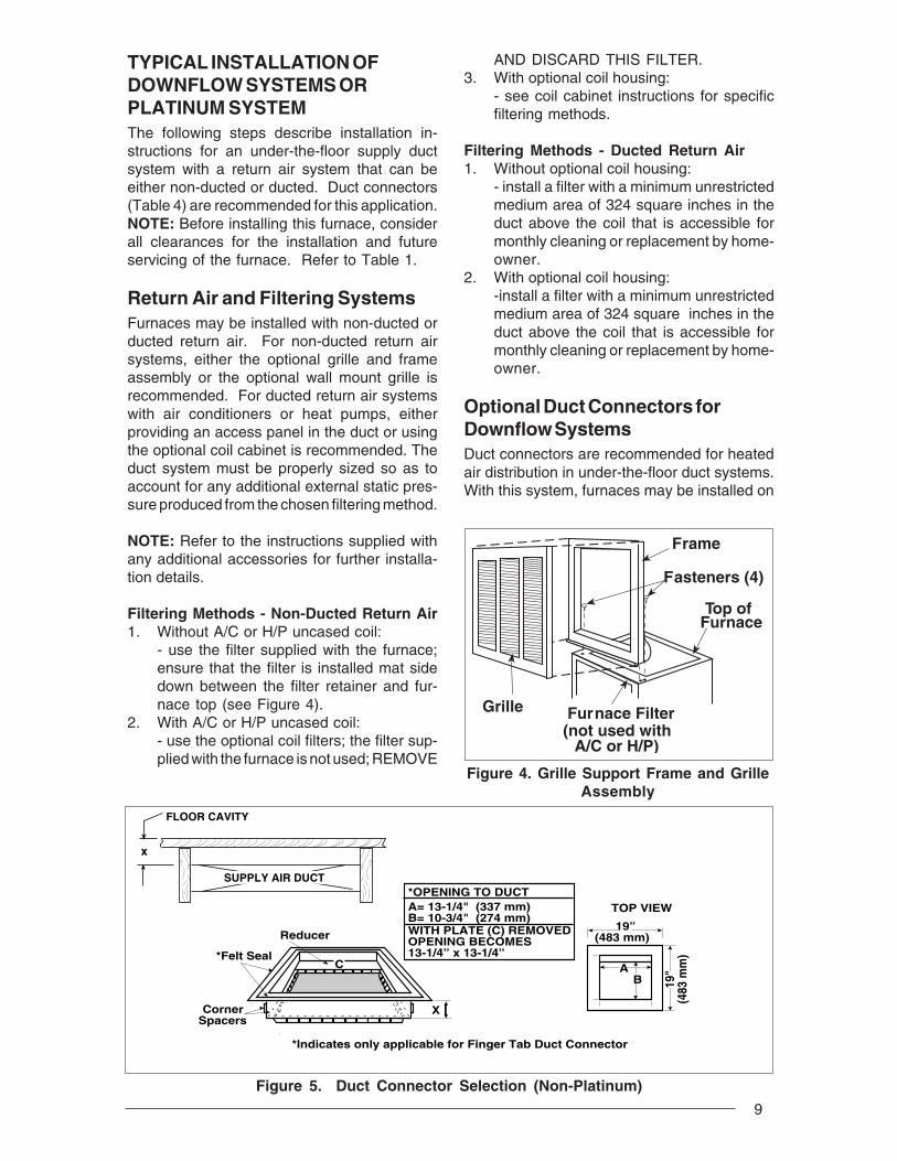
TYPICAL INSTALLATION OFDOWNFLOW SYSTEMS ORPLATINUM SYSTEMThe following steps describe installation in-structions for an under-the-floor supply ductsystem with a return air system that can beeither non-ducted or ducted. Duct connectors(Table 4) are recommended for this application.NOTE: Before installing this furnace, considerall clearances for the installation and futureservicing of the furnace. Refer to Table 1.
Return Air and Filtering SystemsFurnaces may be installed with non-ducted orducted return air. For non-ducted return airsystems, either the optional grille and frameassembly or the optional wall mount grille isrecommended. For ducted return air systemswith air conditioners or heat pumps, eitherproviding an access panel in the duct or usingthe optional coil cabinet is recommended. Theduct system must be properly sized so as toaccount for any additional external static pres-sure produced from the chosen filtering method.
NOTE: Refer to the instructions supplied withany additional accessories for further installa-tion details.
Filtering Methods - Non-Ducted Return Air1. Without A/C or H/P uncased coil:
- use the filter supplied with the furnace;ensure that the filter is installed mat sidedown between the filter retainer and fur-nace top (see Figure 4).
2. With A/C or H/P uncased coil:- use the optional coil filters; the filter sup-plied with the furnace is not used; REMOVE
AND DISCARD THIS FILTER.3. With optional coil housing:
- see coil cabinet instructions for specificfiltering methods.
Filtering Methods - Ducted Return Air1. Without optional coil housing:
- install a filter with a minimum unrestrictedmedium area of 324 square inches in theduct above the coil that is accessible formonthly cleaning or replacement by home-owner.
2. With optional coil housing:-install a filter with a minimum unrestrictedmedium area of 324 square inches in theduct above the coil that is accessible formonthly cleaning or replacement by home-owner.
Optional Duct Connectors forDownflow SystemsDuct connectors are recommended for heatedair distribution in under-the-floor duct systems.With this system, furnaces may be installed on
Figure 5. Duct Connector Selection (Non-Platinum)
Frame
Top ofFurnace
Fasteners (4)
Grille Furnace Filter (not used with
A/C or H/P)
Figure 4. Grille Support Frame and GrilleAssembly

10
combustible flooring without a separate sub-base. Also, the furnace rear mounting plate(see Figure 3) supplied with the duct connec-tors is recommended for use with this type ofinstallation.
Selecting Duct ConnectorNon Platinum Duct Connector1. Determine depth of floor cavity from sur-
face of floor to top of supply air duct (seeFigure 5).
2. Select appropriate model from Table 4which matches X-dimension of floor cavity.To maximize air delivery, remove reducer(C in Figure 5) to obtain largest open areathat will fit duct/floor construction.NOTE: Duct connectors may beinstalled in any one of four positions.
Platinum Duct Connector1. The 14” round duct connector (903896) is
designed to connect directly to a 14” flex-duct.
Preparing Floor Opening(s)1. Mark floor opening(s) as shown in Figure
6. Provide minimum clearances at rear andright side walls of closet or alcove forinstallation of furnace and wiring.
2. Cut floor opening on outside edge of markedline so that opening is slightly larger thanarea marked.
3. Additional provisions may be necessaryfor optional air conditioning or heat pump ifrefrigerant lines are installed elsewherethan at the front of the furnace.
4. The refrigerant and entrance supply open-ing dimensions may be adjusted ± 1/2”.
2-3/8" MIN(60 mm)
"6-1/4
23-3/4"(603 mm)
20"
3/4"
"10
14-1/2"(368 mm)
3" (76 mm)
"4-1/4 "5 "3-3/8
REAR WALL OF ENCLOSURE
Furnace Outer Door
Optional Supply Wire Entrance
OptionalRefrigerant
Line
(Not requiredfor Platinum)
Center Line
17"(432 mm)
14-1/2"(368 mm)
16-5/8"(422 mm)
(254 mm)
(86 mm)(127 mm)(108 mm)
(159 mm)
(19 mm)
(508 mm)
3-3/4"(95 mm)
Furnace Outline
A/C Or HP
Figure 6. Downflow Floor Cutout Locations (nominal dimensions)
Table 4. Floor Cavity Sizes
If “X” Use Duct Connectorfloor cavity is: Model Part Number
English Metric (mm) Finger Tab Screw Down
7/8" 22 901987 9040082" 51 901988 904009
4 1/4" 108 901989 9040106 1/4" 159 901990 9040118 1/4" 210 901991 90401210 1/4" 260 901992 90401312 1/4" 311 901993 904014

11
Rear Wall
Cut-out Area
Optional Supply Entrance
Mounting Plate
Floor Opening
Refrigerant Line Opening
Supply Air Duct
Cut Duct Opening1/16th. Larger Than Plenum Connector
Rear Wall
Secure Duct Connector &Mtg Plate With 2 Flat Head Screws or Nails At Dimpled Locations
Refrigerant Line Opening
Supply Air Duct
Mounting Plate
Plenum Bend Connector TabsUnder Duct Opening
Figure 7. Rear Mounting Plate
Figure 8. Duct Connector (Non Platinum)
temperature rating of 200° F and meet allother applicable codes and standards.
1. Place duct connector through opening infloor. See Figure 9.
2. Connect 14” supply duct.
Method B1. Place duct connector through floor opening
with bottom tabs resting on top of supply airduct. Mark cutout area around inside of tabs.
2. Remove duct connector and cut out ductopening slightly larger than area marked.
3. If using optional rear mounting plate (sup-
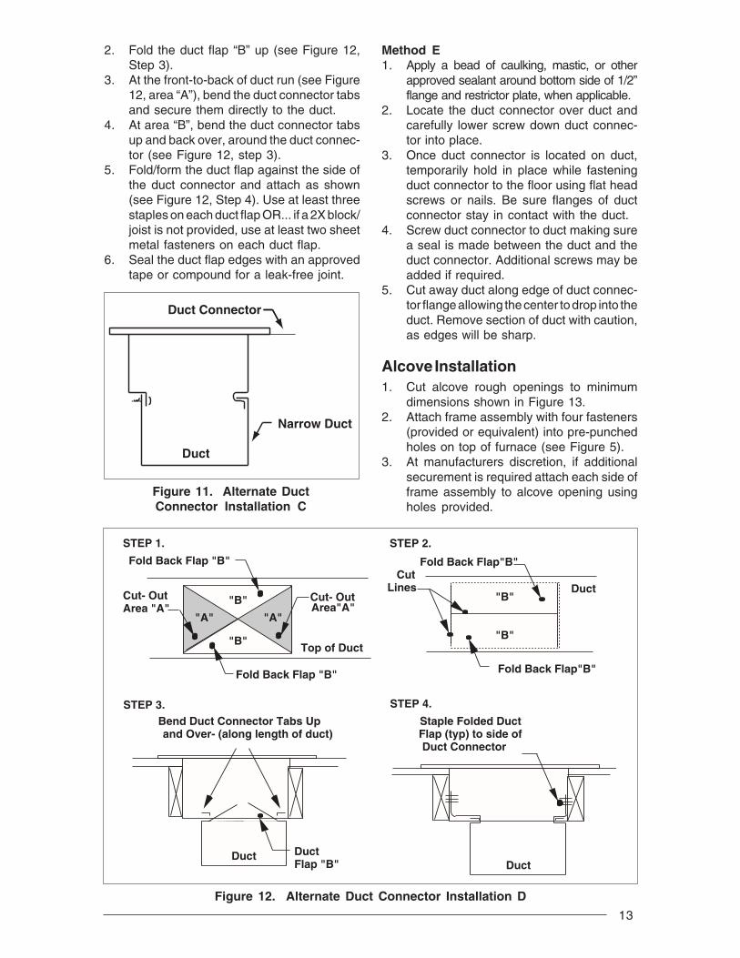
Installing Duct ConnectorNOTE: The duct connector is designed for useon ducts down to 12" wide. On typical ducts, thefinger tab duct connector may be installed usingMethod B. On narrow ducts, there may beinsufficient clearance to bend the tabs on twosides of the finger tab duct connector. In suchcases, use Method C or D. For screw downduct connector use method E. For Platinummodels always use method A.
Method A - Platinum SeriesNOTE: Flex duct used must have a minimum

12
Figure 9. Platinum Duct Connector
Mounting Plate
DuctConnector
Secure Duct Connector and Mounting Plate with 2 Flat-Head Screws or Nails
14" Supply Connection
plied with duct connector), install it to backedge of floor opening (see Figure 7). Re-install duct connector in floor opening. Ashim may be used, if necessary, to ensurethe furnace is level.
4. Secure duct connector to floor with two flat-head fasteners at dimpled locations (seeFigure 8).
5. Secure connector to duct by bending bot-tom tabs under and up against duct sur-faces (see Figure 10).
Figure 10. Duct Connector Installation B
Method C1. Attach tabs to sides of duct (one on each
side) using sheet metal fasteners or othermethod, ensuring that the duct connectoris secure and sealed to the duct (seeFigure 11).
2. Seal the duct flap edges with an approvedtape or compound for a leak-free joint.
Method D1. Score and cut top of metal duct as indicated in
Figure 12, Step 1 or Step 2. If using Step 1, alsocut out metal from the shaded area “A”.
TABS
DUCT
1. INSERT DUCT CONNECTORINTO DUCT CUT-OUT
TABS
DUCT
2. BEND BOTTOM TABS OVERAND ONTO THE UNDER-NEATH DUCT SURFACE
13
Method E1. Apply a bead of caulking, mastic, or other
approved sealant around bottom side of 1/2”flange and restrictor plate, when applicable.
2. Locate the duct connector over duct andcarefully lower screw down duct connec-tor into place.
3. Once duct connector is located on duct,temporarily hold in place while fasteningduct connector to the floor using flat headscrews or nails. Be sure flanges of ductconnector stay in contact with the duct.
4. Screw duct connector to duct making surea seal is made between the duct and theduct connector. Additional screws may beadded if required.
5. Cut away duct along edge of duct connec-tor flange allowing the center to drop into theduct. Remove section of duct with caution,as edges will be sharp.
Alcove Installation1. Cut alcove rough openings to minimum
dimensions shown in Figure 13.2. Attach frame assembly with four fasteners
(provided or equivalent) into pre-punchedholes on top of furnace (see Figure 5).
3. At manufacturers discretion, if additionalsecurement is required attach each side offrame assembly to alcove opening usingholes provided.
2. Fold the duct flap “B” up (see Figure 12,Step 3).
3. At the front-to-back of duct run (see Figure12, area “A”), bend the duct connector tabsand secure them directly to the duct.
4. At area “B”, bend the duct connector tabsup and back over, around the duct connec-tor (see Figure 12, step 3).
5. Fold/form the duct flap against the side ofthe duct connector and attach as shown(see Figure 12, Step 4). Use at least threestaples on each duct flap OR... if a 2X block/joist is not provided, use at least two sheetmetal fasteners on each duct flap.
6. Seal the duct flap edges with an approvedtape or compound for a leak-free joint.
Staple Folded Duct Flap (typ) to side of Duct Connector
Duct
STEP 4.
Cut- Out Area "A"
STEP 1.
"B"
"B" Cut- Out Area"A"
Fold Back Flap "B"
Fold Back Flap "B"
Top of Duct
"A" "A"
"B"
"B"
Fold Back Flap"B"
Cut Lines Duct
Fold Back Flap"B"
STEP 2.
STEP 3.Bend Duct Connector Tabs Up and Over- (along length of duct)
Duct Flap "B"
Duct
Figure 12. Alternate Duct Connector Installation D
Duct
Duct Connector
Narrow Duct
Figure 11. Alternate DuctConnector Installation C

14
20"(508 mm)
24 3/4"(629 mm)
A/C or H/PCoil
Wall Panel
Coil Air Filters
ReturnAir
Grille
Floor
56"(1423 mm)
29"( 737 mm)
27"(686 mm)
FurnaceFront
18"NearestWall orPartition
Figure 13. Typical Alcove Installation Figure 14. Typical Closet Installation
Wall-MountReturn Air Grille
Holes (4)
ClosetDoor
4. Attach return air grille to frame assembly byhooking grille over flange on top of frameand into channel on bottom.
Closet InstallationNOTE: For closet installations, the return airgrille mounting frame is not used since thefurnace is located inside the closet (see Figure14 and 15).1. Cut return air opening in desired position in
door or wall, preferably above top of fur-nace. Refer to Table 1 for return air openingrequirements.
2. Insert four fasteners, securing grille to dooror wall.
Furnace Installation1. Install 240V supply circuit(s) and 24V wir-
ing to closet or alcove (see Figure 16 forappropriate locations).
2. Remove refrigerant line knockouts in fur-nace only when installing indoor coil of anair conditioner or heat pump system, or forhook-up of a VentilAire accessory whenthe furnace is used in the upflow position.Refer to instructions supplied with acces-sory equipment.
3. Remove unit front door and slide back untilbottom slots in rear of unit engage with bothtabs of optional rear mounting plate, OR...If mounting plate is not used, an equivalentmethod of securing the rear of the unit may
Figure 15. Closet Installation
0" SideClearanceto FurnaceCabinet
Provide min. 235sq. in. (1516 cm )open free area infront or side wallor in top ofcloset door
CLOSET DOOR
6"(152 mm)
0" SideClearanceto FurnaceCabinet
Provide min. 250sq. in. (1613 cm2 )open free area infront or side wallor in top ofcloset door
CLOSET DOOR
1"(25 mm)
Standard Closet Installation
Special 1" Clearance
15
be used as long as it prevents displace-ment during transport if used in a manufac-tured home.
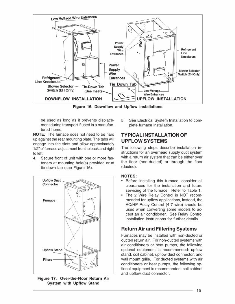
NOTE: The furnace does not need to be hardup against the rear mounting plate. The tabs willengage into the slots and allow approximately1/2” of furnace adjustment front to back and rightto left.4. Secure front of unit with one or more fas-
teners at mounting hole(s) provided or attie-down tab (see Figure 16).
Figure 17. Over-the-Floor Return AirSystem with Upflow Stand
Upflow DuctConnector
Furnace
Filters
Upflow Stand
Low Voltage Wire Entrances
RefrigerantLine Knockouts
Blower SelectorSwitch (EH Only)
Tie-Down Tab(See Inset)
PowerSupplyWireEntrances
PowerSupply
WireEntrances
Blower SelectorSwitch (EH Only)
RefrigerantLineKnockouts
Low VoltageWire Entrances
Figure 16. Downflow and Upflow Installations
Tie Down Tab
DOWNFLOW INSTALLATION UPFLOW INSTALLATION
5. See Electrical System Installation to com-plete furnace installation.
TYPICAL INSTALLATION OFUPFLOW SYSTEMSThe following steps describe installation in-structions for an overhead supply duct systemwith a return air system that can be either overthe floor (non-ducted) or through the floor(ducted).
NOTES:• Before installing this furnace, consider all
clearances for the installation and futureservicing of the furnace. Refer to Table 1.
• The 2 Wire Relay Control is NOT recom-mended for upflow applications, instead, theAC/HP Relay Control (4-7 wire) should beused when converting some models to ac-cept an air conditioner. See Relay Controlinstallation instructions for further details.
Return Air and Filtering SystemsFurnaces may be installed with non-ducted orducted return air. For non-ducted systems withair conditioners or heat pumps, the followingoptional equipment is recommended: upflowstand, coil cabinet, upflow duct connector, andwall mount grille. For ducted systems with airconditioners or heat pumps, the following op-tional equipment is recommended: coil cabinetand upflow duct connector.
16
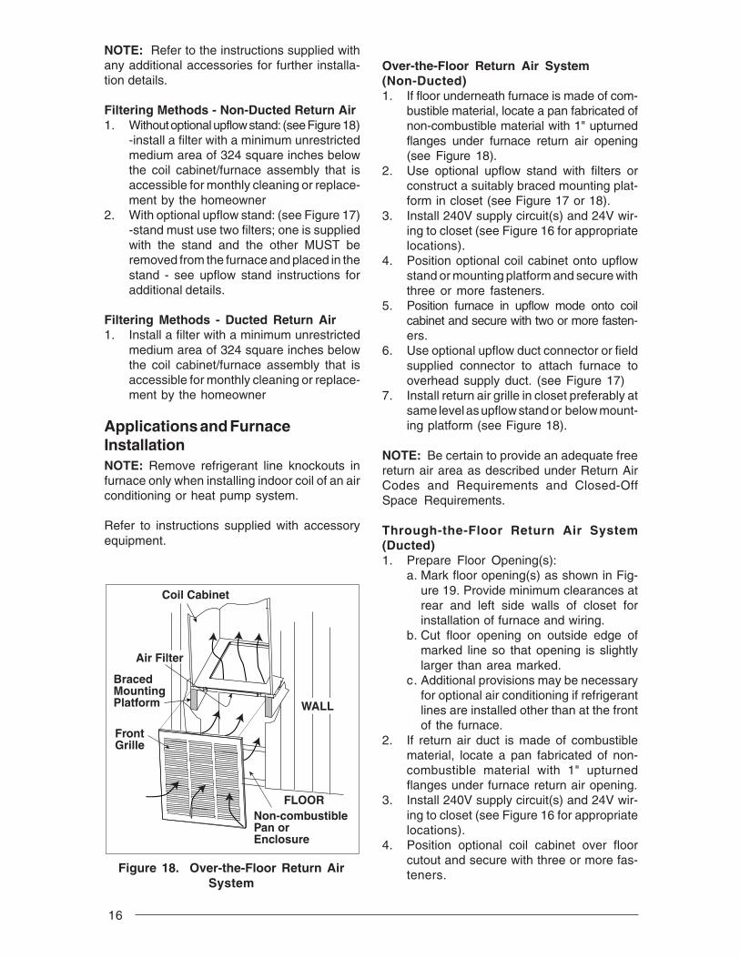
Over-the-Floor Return Air System(Non-Ducted)1. If floor underneath furnace is made of com-
bustible material, locate a pan fabricated ofnon-combustible material with 1" upturnedflanges under furnace return air opening(see Figure 18).
2. Use optional upflow stand with filters orconstruct a suitably braced mounting plat-form in closet (see Figure 17 or 18).
3. Install 240V supply circuit(s) and 24V wir-ing to closet (see Figure 16 for appropriatelocations).
4. Position optional coil cabinet onto upflowstand or mounting platform and secure withthree or more fasteners.
5. Position furnace in upflow mode onto coilcabinet and secure with two or more fasten-ers.
6. Use optional upflow duct connector or fieldsupplied connector to attach furnace tooverhead supply duct. (see Figure 17)
7. Install return air grille in closet preferably atsame level as upflow stand or below mount-ing platform (see Figure 18).
NOTE: Be certain to provide an adequate freereturn air area as described under Return AirCodes and Requirements and Closed-OffSpace Requirements.
Through-the-Floor Return Air System(Ducted)1. Prepare Floor Opening(s):
a. Mark floor opening(s) as shown in Fig-ure 19. Provide minimum clearances atrear and left side walls of closet forinstallation of furnace and wiring.
b. Cut floor opening on outside edge ofmarked line so that opening is slightlylarger than area marked.
c. Additional provisions may be necessaryfor optional air conditioning if refrigerantlines are installed other than at the frontof the furnace.
2. If return air duct is made of combustiblematerial, locate a pan fabricated of non-combustible material with 1" upturnedflanges under furnace return air opening.
3. Install 240V supply circuit(s) and 24V wir-ing to closet (see Figure 16 for appropriatelocations).
4. Position optional coil cabinet over floorcutout and secure with three or more fas-teners.
NOTE: Refer to the instructions supplied withany additional accessories for further installa-tion details.
Filtering Methods - Non-Ducted Return Air1. Without optional upflow stand: (see Figure 18)
-install a filter with a minimum unrestrictedmedium area of 324 square inches belowthe coil cabinet/furnace assembly that isaccessible for monthly cleaning or replace-ment by the homeowner
2. With optional upflow stand: (see Figure 17)-stand must use two filters; one is suppliedwith the stand and the other MUST beremoved from the furnace and placed in thestand - see upflow stand instructions foradditional details.
Filtering Methods - Ducted Return Air1. Install a filter with a minimum unrestricted
medium area of 324 square inches belowthe coil cabinet/furnace assembly that isaccessible for monthly cleaning or replace-ment by the homeowner
Applications and FurnaceInstallationNOTE: Remove refrigerant line knockouts infurnace only when installing indoor coil of an airconditioning or heat pump system.
Refer to instructions supplied with accessoryequipment.
Coil Cabinet
Air Filter
BracedMountingPlatform
FrontGrille
Non-combustiblePan orEnclosure
WALL
FLOOR
Figure 18. Over-the-Floor Return AirSystem

17
5. Position furnace onto coil cabinet and se-cure with two or more fasteners.
6. Use optional upflow duct connector or fieldsupplied connector to attach furnace tooverhead supply duct (see Figure 17).
ELECTRICAL SYSTEMINSTALLATION
! WARNING:To avoid the risk of electrical shock,personal injury or death, disconnectall electrical power to the unit beforeperforming any maintenance orservice. The unit may have more thanone electrical power supply.
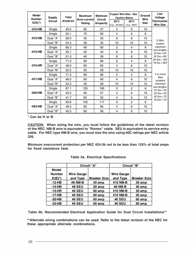
Codes, Specifications, andRequirementsThe wiring, installation, and electrical hookup ofthis furnace must comply with the NationalElectrical Code (or the Canadian ElectricalCode) and all regulations of local authoritieshaving jurisdiction. See Table 6a & 6b for mini-mum circuit ampacity, maximum over-currentprotection, and recommended wire size. See
1 3/4" MIN(45 mm)
23 3/4"(604 mm)
3/4"(20 mm)
20"(508 mm)
17 1/2"(445 mm)
14"(356 mm)
5 3/4"(147 mm)
3 1/8"(80 mm)
3"(73 mm)Furnace
Outer Door
For OptionalA/C Or H/P
REAR WALL OF ENCLOSURECENTER LINE
Furnace Outline18 5/8"
(474 mm)
Figure 19. Upflow Floor Cutout Locations (nominal dimensions)
the unit wiring diagram for other wiring details.Supply-circuit requirements are as follows:• -010 model is factory-wired for single-branch
supply circuit only.• -012 models are factory-wired for single-
branch supply circuit (single-circuit kit in-stalled). Dual-branch circuit can be used byremoving factory-installed single-circuit kit(see Figures 20 and 21).
• -015, -017, -020 and -023 models arefactory-wired for dual-branch supply circuit.Single-branch circuit can be used byinstalling optional single-circuit kit .
! IMPORTANT:Note: Circuit breakers installed withinthis unit are for short-circuitprotection of the internal wiring andto serve as a disconnect. Circuitbreakers installed within this unit DONOT provide over-current protectionof the supply wiring and therefore maybe sized larger than the branch circuitprotection.

18
OptionalSingle CircuitAdaptor Kit
Circuit BreakerBracket
60A60A
ON
ON
OF
FO
FF
CircuitBreaker
WireAssemblies
(FactoryInstalled) Supply Service
Wire Connection With Single Circuit Adaptor Kit
Connecting Supply Service Wires1. Remove right-hand control panel (when
viewing in downflow position).2. Locate power supply hole plugs in side of
unit and in bottom of unit. Remove appro-priate plug(s) or knockout opening appli-cable to recommended wire size(s).
3. Install listed cable connector(s) inopening(s). If metal-sheathed conduit isused for incoming power line(s), provide anapproved metal clamp on conduit andsecure it in entrance knockout.
4. Insert supply service wire(s) through cableconnector(s) and connect wires to circuitbreakers (Figures 20 and 21).NOTE: To install single-circuit kit, performstep 5. If single-circuit kit installation is notnecessary, go to step 6.
5. To install single-circuit kit:a. Loosen lugs at supply side of circuit
breakers.b. Remove cover from single-circuit kit (if
supplied).
Figure 20. Installation of Optional Single Circuit Adaptor Kit
Figure 21. Installation of Supply Service Wires
c. Insert metal buss bars of kit into lugs ofcircuit breaker.
d. Tighten lugs securely (45 in.-lbs.recommended).
6. Connect service ground wire(s) to ground-ing lug(s) provided. One ground is requiredfor each supply circuit used.
! WARNING:To avoid personal injury or propertydamage, make certain that the motorleads cannot come into contact withnon-insulated metal components of theunit.
Blower Installation:1. Turn off all electrical supply circuits to the
furnace at the main service panel.2. Remove furnace front door and switch
furnace circuit breaker(s) to “OFF”.60A
60AO
NO
N
OF
FO
FF
CircuitBreaker
WireAssemblies
(FactoryInstalled)
Supply ServiceWire Connection Without SingleCircuit Adaptor Kit
Circuit BreakerBracket
19
3. Disconnect the motor plug from the controlpanel receptacle.
4. Remove one screw from left side of blowerand three screws from right side of blower;slide blower forward and remove.
5. Install new blower ensuring the side flangesengage under side mounting tabs (three onone side, one on the other) and the long tabin the rear.
6. Replace screws previously removed fromblower.
7. Connect the motor plug to the control panelreceptacle.
8. Switch circuit breaker(s) to “ON”, reinstallfurnace front door, and turn on electricalsupply circuits to the furnace.
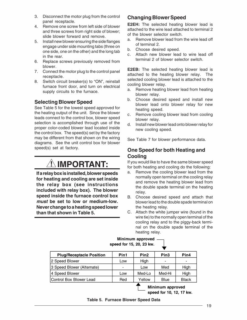
Selecting Blower SpeedSee Table 5 for the lowest speed approved forthe heating output of the unit. Since the blowerleads connect to the control box, blower speedselection is accomplished through use of theproper color-coded blower lead located insidethe control box. The speed(s) set by the factorymay be different from that shown on the wiringdiagrams. See the unit control box for blowerspeed(s) set at factory.
! IMPORTANT:If a relay box is installed, blower speedsfor heating and cooling are set insidethe relay box (see instructionsincluded with relay box). The blowerspeed inside the furnace control boxmust be set to low or medium-low.Never change to a heating speed lowerthan that shown in Table 5.
Table 5. Furnace Blower Speed Data
Changing Blower SpeedE2EH: The selected heating blower lead isattached to the wire lead attached to terminal 2of the blower selector switch.a. Remove blower lead from the wire lead off
of terminal 2.b. Choose desired speed.c. Attach new blower lead to wire lead off
terminal 2 of blower selector switch.
E2EB: The selected heating blower lead isattached to the heating blower relay. Theselected cooling blower lead is attached to thecooling blower relay.a. Remove heating blower lead from heating
blower relay.b. Choose desired speed and install new
blower lead onto blower relay for newheating speed.
c. Remove cooling blower lead from coolingblower relay.
d. Install new blower lead onto blower relay fornew cooling speed.
See Table 7 for blower performance data.
One Speed for both Heating andCoolingIf you would like to have the same blower speedfor both heating and cooling do the following:a. Remove the cooling blower lead from the
normally open terminal on the cooling relayand remove the heating blower lead fromthe double spade terminal on the heatingrelay.
B. Choose desired speed and attach thatblower lead to the double spade terminal onthe heating relay.
C. Attach the white jumper wire (found in thewire tie) to the normally open terminal of thecooling relay and to the piggy-back termi-nal on the double spade terminal of theheating relay.
Plug/Receptacle Position Pin1 Pin2 Pin3 Pin4
2 Speed Blower Low High - -
3 Speed Blower (Alternate) - Low Med High
4 Speed Blower Low Med-Lo Med-Hi High
Control Box Blower Lead Red Yellow Blue Black
Minimum approved speed for 10, 12, 17 kw.
Minimum approved speed for 15, 20, 23 kw.
20
Circuit "A" Circuit "B"Model
Number Wire Gauge Wire GaugeE2E(*) and Type Breaker Size and Type Breaker Size-12-HB #8 NM-B 40 amp #10 NM-B 30 amp-15-HB #8 SEU 50 amp #8 NM-B 40 amp-15-HR #6 SEU 60 amp #10 NM-B 30 amp-17-HB #6 SEU 60 amp #10 NM-B 30 amp-20-HB #6 SEU 60 amp #6 SEU 60 amp-23-HB #6 SEU 60 amp #6 SEU 60 amp
Copper Wire Size - SeeCaution Below
60°C 90°C( e.g ., R o mex) ( e.g . , SEU )
-010-HB Single 45.5 60 57 4 6 10
Single 52.1 70 65 4 6 8
Dual "A" 28.0 40 35 8 8 10
Dual "B" 24.2 30 30 10 10 10
Single 66.3 90 83 2 4 8
Dual "A" 35.1 50 44 6 8 10
Dual "B" 31.3 40 39 8 8 10
Single 71.3 90 89 2 4 8
Dual "A" 48.0 60 60 4 6 10
Dual "B" 22.5 30 28 10 10 10
Single 71.3 90 89 2 4 8
Dual "A" 48.0 60 60 4 6 10
Dual "B" 22.5 30 28 10 10 10
Single 87.1 125 109 0 2 6
Dual "A" 45.5 60 57 4 6 10
Dual "B" 41.7 60 52 4 6 10
Single 93.8 125 117 0 2 6
Dual "A" 48.0 60 60 4 6 10
Dual "B" 45.5 60 56 4 6 10
-012-HB
-015-HB
-017-HB
-020-HB
-023-HB
-015-HR
2-Wire system
maximum wire lengths:24 Ga.= 55' 22 Ga.= 90' 20 Ga.= 140' 18 Ga.= 225'
4 or more Wire
systems maximum
wire lengths: 24 Ga.= 25' 22 Ga.= 45' 20 Ga.= 70' 18 Ga= 110'
LowVoltage
ThermostatWire Size
GroundWireSize
Minimum Circuit
Ampacity
Maximum Over-current
Rating
TotalAmperes
SupplyCircuit
ModelNumberE2E(*)
* Can be H or B
CAUTION: When sizing the wire, you must follow the guidelines of the latest revisionof the NEC. NM-B wire is equivalent to “Romex” cable. SEU is equivalent to service entrycable. For NEC type NM-B wire, you must size the wire using 60C ratings per NEC article326.
Minimum overcurrent protection per NEC 424-3b not to be less than 125% of total ampsfor fixed resistance heat.
Table 6a. Electrical Specifications
Table 6b. Recommended Electrical Application Guide for Dual Circuit Installations**
**Alternate wiring combinations can be used. Refer to the latest revision of the NEC forthese appropriate alternate combinations.

21
Installing Control Circuit WiringNOTE: Installation of a five-wire thermostatcircuit is recommended to provide for futureaddition of a heat/cool thermostat.1. Install the 24V control-circuit cable through
plastic bushing at either side of furnace.a. For models without a relay box, connect
wires to furnace at blower plug pigtails (seewiring diagrams). Secure all connectionswith wire nuts.
b. For units with a relay box installed, makewiring connections at relay box low-volt-age terminal board. (See relay box instal-lation instructions.)
2. Route control circuit wiring to wallthermostat and outdoor section, if installed.(See relay box installation instructions ifapplicable.)
3. Set anticipator per Table 8 or per themarking on the unit.
4. See Figure 31 (non-Platinum) and Figure32 (Platinum) for E2EB thermostat con-nections.
SYSTEM CHECKOUT
Checking Installation1. Refer to appropriate wiring diagram and
recheck all wiring connections. Ensurethat all connections are tight.
2. Check blower motor and relay boxconnectors for proper connection.
3. Reinstall control box cover(s).4. Switch circuit breaker(s) to “ON” position.5. Set furnace blower selector switch (see
Figure 16) to “AUTO” (EH Units only).6. Replace outer furnace door.7. Check all duct connections and tape for air
leakage.
Table 7. Blower Performance
Standard E2EH Blower with Filter, @ 0.3" ESP
Pin No. Speed CFM
#1 Low 840
#2 High 1160
4-Ton Blower with Coil andCoil and Filters, @ 0.3" ESP
Pin No. Speed CFM
#1 Low 880
#2 Med.-Low 1170
#3 Med.-High 1310
#4 High 1460
5-Ton Blower, with Coil and Coil Filters, @ 0.3" ESP
Pin No. Speed CFM
#1 Low 990
#2 Med.-Low 1320
#3 Med.-High 1620
#4 High 1790
Table 8. Anticipator Settings
Furnace ThermostatModel Anticipator Setting
EH-10, 12, 15 0.30EH-17, 20, 23, 15 HR 0.60
EB-10, 12, 15 0.50EB-17, 20, 23, 15 HR 0.75
Table 9. Clearances
ALL MODELS CLOSET ALCOVE
Front ‡ 6" 18"
Back 0" 0"
Sides 0"† 0"†
Top 0" 0"
Top and Sides of Duct 0" 0"
Bottom of Duct 0" 0"
‡ Service Clearance† For upflow application using upflow stand, 1" minimum per side.

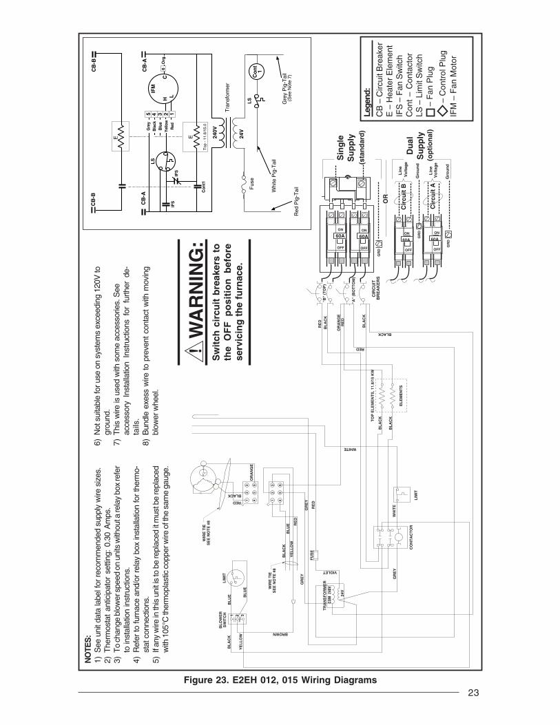
22Figure 22. E2EH 010 Wiring Diagrams
Lege
nd:
CB
– C
ircui
t Bre
aker
E –
Hea
ter
Ele
men
tIF
S –
Fan
Sw
itch
Con
t –
Con
tact
orLS
– L
imit
Sw
itch
– F
an P
lug
– C
ontr
ol P
lug
IFM
– F
an M
otor
NO
TES
:1)
See
uni
t dat
a la
bel f
or re
com
men
ded
supp
ly w
ire s
izes
.2)
The
rmos
tat
antic
ipat
or s
ettin
g: 0
.30
Am
ps.
3)T
o ch
ange
blo
wer
spe
eds
on u
nits
with
out
a re
lay
box
inst
alle
d re
fer
to i
nsta
llatio
n in
stru
ctio
ns.
4)R
efer
to fu
rnac
e an
d/or
rel
ay b
ox in
stal
latio
n fo
r th
erm
o-st
at c
onne
ctio
ns.
5)If
any
wire
in th
is u
nit i
s to
be
repl
aced
it m
ust b
e re
plac
edw
ith 1
05°C
ther
mop
last
ic c
oppe
r wire
of t
he s
ame
gaug
e.
! W
AR
NIN
G:
Sw
itch
cir
cuit
bre
aker
s to
the
OF
F p
osi
tio
n b
efo
rese
rvic
ing
th
e fu
rnac
e.
6)N
ot s
uita
ble
for u
se o
n sy
stem
s ex
ceed
ing
120V
togr
ound
.7)
Thi
s w
ire is
use
d w
ith s
ome
acce
ssor
ies.
See
acc
es-
sory
Ins
talla
tion
Inst
ruct
ions
for
fur
ther
det
ails
.8)
Bun
dle
exes
s w
ire to
pre
vent
con
tact
with
mov
ing
blow
er w
heel
.
240V
Tra
nsfo
rmer
Co
nt
1
24V
Red
Pig
-Tai
l
Whi
te P
ig-T
ail
Co
nt
1
CB
-AC
B-A
IFS
Top
- 1
0.0
6
EC
on
t 1
IFS
Org
.
(See
Not
e 7)
Gre
y P
ig-T
ail
Fus
eL
S
2345 1
Gre
y
Bla
ck
Blu
e
Yel
low
Red
H LC
IFM
LS
LIM
IT
BL
UE
BL
UE
BL
OW
ER
SW
ITC
H 1 2 3
60A
ON
OFF
Cir
cuit
AL
ine
Vo
ltag
e
GR
DG
rou
nd
Su
pp
ly
CIR
CU
IT
BR
EA
KE
R
TR
AN
SF
OR
ME
R24
0V
24V G
RE
Y
YELLOW
BL
AC
K
CO
NT
AC
TO
R
ORANGE
BROWN
WH
ITE
LIM
IT
BL
AC
K
BL
AC
K
EL
EM
EN
TS
TO
P E
LE
ME
NT
S, 1
0.0
KW
OR
AN
GE
RE
D
RED
RED
BL
AC
KB
LA
CK
BLACK
32
1
32
1
65
4
65
4
HL
C
YE
LL
OW
RE
D
BL
UE
BL
AC
K
VIOLET
WHITE
RED
BLACK
CO
M
GR
EY
FU
SE
WIR
E T
IES
EE
NO
TE
#8
"A"
(BOT
TOM
)
WIR
E T
IES
EE
NO
TE
#8
23
! W
AR
NIN
G:
Sw
itch
cir
cuit
bre
aker
s to
the
OF
F p
osi
tio
n b
efo
rese
rvic
ing
th
e fu
rnac
e.
Figure 23. E2EH 012, 015 Wiring Diagrams
NO
TES
:1)
See
uni
t dat
a la
bel f
or re
com
men
ded
supp
ly w
ire s
izes
.2)
The
rmos
tat
antic
ipat
or s
ettin
g: 0
.30
Am
ps.
3)T
o ch
ange
blo
wer
spe
ed o
n un
its w
ithou
t a re
lay
box
refe
rto
inst
alla
tion
inst
ruct
ions
.4)
Ref
er to
furn
ace
and/
or r
elay
box
inst
alla
tion
for
ther
mo-
stat
con
nect
ions
.5)
If an
y w
ire in
this
uni
t is
to b
e re
plac
ed it
mus
t be
repl
aced
with
105
°C th
erm
opla
stic
cop
per w
ire o
f the
sam
e ga
uge.
6)N
ot s
uita
ble
for u
se o
n sy
stem
s ex
ceed
ing
120V
togr
ound
.7)
Thi
s w
ire is
use
d w
ith s
ome
acce
ssor
ies.
See
acce
ssor
y In
stal
latio
n In
stru
ctio
ns f
or f
urth
er d
e-ta
ils.
8)B
undl
e ex
ess
wire
to p
reve
nt c
onta
ct w
ith m
ovin
gbl
ower
whe
el.
Lege
nd:
CB
– C
ircui
t Bre
aker
E –
Hea
ter
Ele
men
tIF
S –
Fan
Sw
itch
Con
t –
Con
tact
orLS
– L
imit
Sw
itch
– F
an P
lug
– C
ontr
ol P
lug
IFM
– F
an M
otor
240V
Co
nt1
CB
-AC
B-A
CB
-BC
B-B
Tra
nsfo
rmer
Top
- 1
1.6/
15.0
6
E 24V
Red
Pig
-Tai
l
Whi
te P
ig-T
ail
Org
.
(See
Not
e 7)
Gre
y P
ig-T
ail
E
Fus
eC
on
t1
LS
2345 1
Gre
yB
lack
Blu
eY
ello
wR
ed
H LC
IFM
IFS
IFS
LS
L
C
H
WH
ITE
LIM
IT
GR
EY
RE
D
WHITE
FU
SE
RE
D
BL
UE
BL
AC
K
YE
LL
OW
BROWN
GR
EY
WIR
E T
IES
EE
NO
TE
#8
BL
OW
ER
SW
ITC
H
YE
LL
OW
BL
AC
K1 2 3
BL
UE
BL
UE
LIM
IT
32
1
65
4
32
1
65
4
OR
AN
GE
WIR
E T
IES
EE
NO
TE
#8
CIR
CU
IT
BR
EA
KE
RS
60A
ON
OFF
GR
D
Sin
gle
Su
pp
ly(s
tan
dar
d)
OR
Cir
cuit
A
Cir
cuit
B
GR
D
GR
DG
rou
nd
Du
al
Su
pp
ly(o
pti
on
al)
60A60AONON
OFF OFF
Lin
eV
olt
age
Gro
un
d
Lin
eV
olt
age
60A
ON
OFF
BL
AC
K
BL
AC
K
TO
P E
LE
ME
NT
S, 1
1.6/
15 K
W
OR
AN
GE
RE
D
RED
BL
AC
K
BLACK
BL
AC
KR
ED
EL
EM
EN
TS
TR
AN
SF
OR
ME
R24
0V
24V
GR
EY
CO
NT
AC
TO
R
VIOLET
COM
"B"
(TO
P)
"A"
(BO
TT
OM
)
RED
BLACK
24
! W
AR
NIN
G:
Sw
itch
cir
cuit
bre
aker
s to
the
OF
F p
osi
tio
n b
efo
rese
rvic
ing
th
e fu
rnac
e.
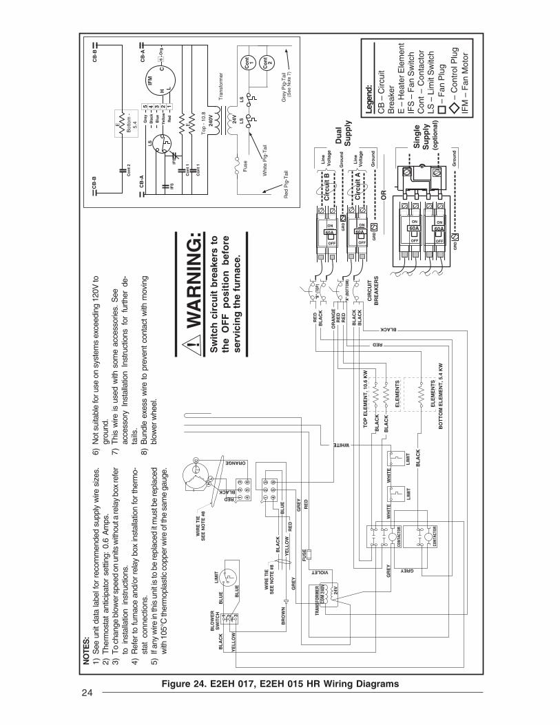
Lege
nd:
CB
– C
ircui
tB
reak
erE
– H
eate
r Ele
men
tIF
S –
Fan
Sw
itch
Con
t –
Con
tact
orLS
– L
imit
Sw
itch
– F
an P
lug
– C
ontr
ol P
lug
IFM
– F
an M
otor
NO
TES
:1)
See
uni
t dat
a la
bel f
or r
ecom
men
ded
supp
ly w
ire s
izes
.2)
The
rmos
tat
antic
ipat
or s
ettin
g: 0
.6 A
mps
.3)
To
chan
ge b
low
er s
peed
on
units
with
out a
rela
y bo
x re
fer
to i
nsta
llatio
n in
stru
ctio
ns.
4)R
efer
to fu
rnac
e an
d/or
rel
ay b
ox in
stal
latio
n fo
r th
erm
o-st
at c
onne
ctio
ns.
5)If
any
wire
in th
is u
nit i
s to
be
repl
aced
it m
ust b
e re
plac
edw
ith 1
05°C
ther
mop
last
ic c
oppe
r wire
of t
he s
ame
gaug
e.
6)N
ot s
uita
ble
for u
se o
n sy
stem
s ex
ceed
ing
120V
togr
ound
.7)
Thi
s w
ire is
use
d w
ith s
ome
acce
ssor
ies.
See
acce
ssor
y In
stal
latio
n In
stru
ctio
ns f
or f
urth
er d
e-ta
ils.
8)B
undl
e ex
ess
wire
to p
reve
nt c
onta
ct w
ith m
ovin
gbl
ower
whe
el.
Figure 24. E2EH 017, E2EH 015 HR Wiring Diagrams
240V
Co
nt
1
CB
-AC
B-A
CB
-BC
B-B
Tra
nsfo
rmer
Bot
tom
-
5.4
Top
- 1
0.8
EC
on
t 1IF
S
Co
nt
2
24V
Red
Pig
-Tai
l
Whi
te P
ig-T
ail
6O
rg.
(See
Not
e 7)
Gre
y P
ig-T
ail
E
Fus
eC
on
t1
LS
Co
nt
2
LS
IFS
2345 1
Gre
y
Bla
ck
Blu
e
Yel
low
Red
H LC
IFM
LS
TO
P E
LE
ME
NT
, 10.
6 K
W
BO
TT
OM
EL
EM
EN
T, 5
.4 K
W
EL
EM
EN
TS
EL
EM
EN
TS
BL
AC
K
BL
AC
K
BL
AC
K
WHITE
FU
SE
RE
D
GR
EY
GR
EY
BR
OW
N
WIR
E T
IES
EE
NO
TE
#8
1 2 3
WIR
E T
IES
EE
NO
TE
#8
BL
AC
K
OR
AN
GE
RE
D
BL
AC
K
ORANGE
RE
DB
LA
CK
RED
BLACK
RE
D
WH
ITE
LIM
IT
CONT
ACTO
R
LIM
IT
VIOLET
WH
ITE
CONT
ACTO
R
GREY
GR
EY
TRAN
SFOR
MER 240V
24V
COM
RE
D
BL
UE
BL
AC
K
YE
LL
OW
BL
OW
ER
SW
ITC
H
YE
LL
OW
BL
AC
KL
IMIT
BL
UE
BL
UE
RED
BLACK1
23
12
3
45
6
45
6HL
C
CIR
CU
IT
BR
EA
KE
RS
"B" (
TOP)
"A" (
BOTT
OM)
60A
ON
OFF
GR
D
Sin
gle
Su
pp
ly
OR
Cir
cuit
A
Cir
cuit
B
GR
D
GR
D
Gro
un
d
Du
al
Su
pp
ly
(op
tio
nal
)
60A60AONON
OFF OFF
Lin
eV
olt
age
Gro
un
d
Lin
eV
olt
age
60A
ON
OFF
Gro
un
d

25Figure 25. E2EH 020, 023 Wiring Diagrams
240V
Co
nt
1
CB
-AC
B-A
CB
-BC
B-B
Tra
nsfo
rmer
Top
-
10.0
/11.
6
Btm
- 1
0.0
E EC
on
t 1
IFS
Co
nt
2
Co
nt
2
24V
Red
Pig
-Tai
l
Whi
te P
ig-T
ail
6O
rg.
(See
Not
e 7)
Gre
y P
ig-T
ail
Fus
eC
on
t1
LS
Co
nt
2
LS
2345 1
Gre
y
Bla
ck
Blu
e
Yel
low
Red
ML
C
IFM
IFS
HM
H
LS
! W
AR
NIN
G:
Sw
itch
cir
cuit
bre
aker
s to
the
OF
F p
osi
tio
n b
efo
rese
rvic
ing
th
e fu
rnac
e.
Lege
nd:
CB
– C
ircui
tB
reak
erE
– H
eate
r Ele
men
tIF
S –
Fan
Sw
itch
Con
t –
Con
tact
orLS
– L
imit
Sw
itch
– F
an P
lug
– C
ontr
ol P
lug
IFM
– F
an M
otor
NO
TES
:1)
See
uni
t dat
a la
bel f
or r
ecom
men
ded
supp
ly w
ire s
izes
.2)
The
rmos
tat
antic
ipat
or s
ettin
g: 0
.6 A
mps
.3)
To
chan
ge b
low
er s
peed
on
units
with
out a
rela
y bo
x re
fer
to i
nsta
llatio
n in
stru
ctio
ns.
4)R
efer
to fu
rnac
e an
d/or
rel
ay b
ox in
stal
latio
n fo
r th
erm
o-st
at c
onne
ctio
ns.
5)If
any
wire
in th
is u
nit i
s to
be
repl
aced
it m
ust b
e re
plac
edw
ith 1
05°C
ther
mop
last
ic c
oppe
r wire
of t
he s
ame
gaug
e.
6)N
ot s
uita
ble
for u
se o
n sy
stem
s ex
ceed
ing
120V
togr
ound
.7)
Thi
s w
ire is
use
d w
ith s
ome
acce
ssor
ies.
See
acce
ssor
y In
stal
latio
n In
stru
ctio
ns f
or f
urth
er d
e-ta
ils.
8)B
undl
e ex
ess
wire
to p
reve
nt c
onta
ct w
ith m
ovin
gbl
ower
whe
el.
WIR
E T
IES
EE
NO
TE
#8
LIM
IT
RE
D
GR
EY
FU
SE
GR
EY
H MH
LM
L
C
WHITE
BL
AC
KB
LA
CK
RE
DR
ED
RE
DR
ED
RE
D
OR
AN
GE
BL
AC
KB
LA
CK
BL
AC
KT
OP
EL
EM
EN
T, 1
0.0/
11.6
KW
BO
TT
OM
EL
EM
EN
T, 1
0.0
KW
EL
EM
EN
TS
EL
EM
EN
TS
WH
ITE
BL
AC
K
LIM
IT
BL
AC
K
BL
AC
K
BL
AC
K
WH
ITE
LIM
IT
WHITE
GR
EY
CONT
ACTO
R
GR
EY
CONT
ACTO
R
WIR
E T
IES
EE
NO
TE
#8
1 2 3
BL
OW
ER
SW
ITC
H
YE
LL
OW
BL
AC
K
BR
OW
N
BL
UE
BL
UE
BL
AC
KB
LU
EY
EL
LO
WR
ED
VIOLET
TRAN
SFOR
MER
240V
24V
COM
12
3
45
6
12
3
45
6BLUE
RED
YELLOW
60A
ON
OFF
GR
D
Sin
gle
Su
pp
ly
OR
Cir
cuit
A
Cir
cuit
B
GR
D
GR
D
Gro
un
d
Du
al
Su
pp
ly
(op
tio
nal
)
60A60AONON
OFF OFF
Lin
eV
olt
age
Gro
un
d
Lin
eV
olt
age
60A
ON
OFF
Gro
un
dC
IRC
UIT
B
RE
AK
ER
S
"B" (
TOP)
"A" (
BOTT
OM)

26
! W
AR
NIN
G:
Sw
itch
cir
cuit
bre
aker
s to
the
OF
F p
osi
tio
n b
efo
rese
rvic
ing
th
e fu
rnac
e.
Figure 26. E2EB 010 Wiring Diagrams
NO
TES
:1)
See
uni
t dat
a la
bel f
or r
ecom
men
ded
supp
ly w
ire s
izes
.2)
The
rmos
tat
antic
ipat
or s
ettin
g: 0
.50
Am
ps.
3)T
o ch
ange
blo
wer
spe
ed o
n un
its w
ithou
t a re
lay
box
refe
rto
ins
talla
tion
inst
ruct
ions
.4)
Ref
er to
furn
ace
and/
or r
elay
box
inst
alla
tion
for
ther
mo-
stat
con
nect
ions
.5)
If an
y w
ire in
this
uni
t is
to b
e re
plac
ed it
mus
t be
repl
aced
with
105
°C th
erm
opla
stic
cop
per w
ire o
f the
sam
e ga
uge.
6)N
ot s
uita
ble
for u
se o
n sy
stem
s ex
ceed
ing
120V
togr
ound
.7)
Thi
s w
ire is
use
d w
ith s
ome
acce
ssor
ies.
See
acce
ssor
y In
stal
latio
n In
stru
ctio
ns f
or f
urth
er d
e-ta
ils.
8)B
undl
e ex
ess
wire
to p
reve
nt c
onta
ct w
ith m
ovin
gbl
ower
whe
el.
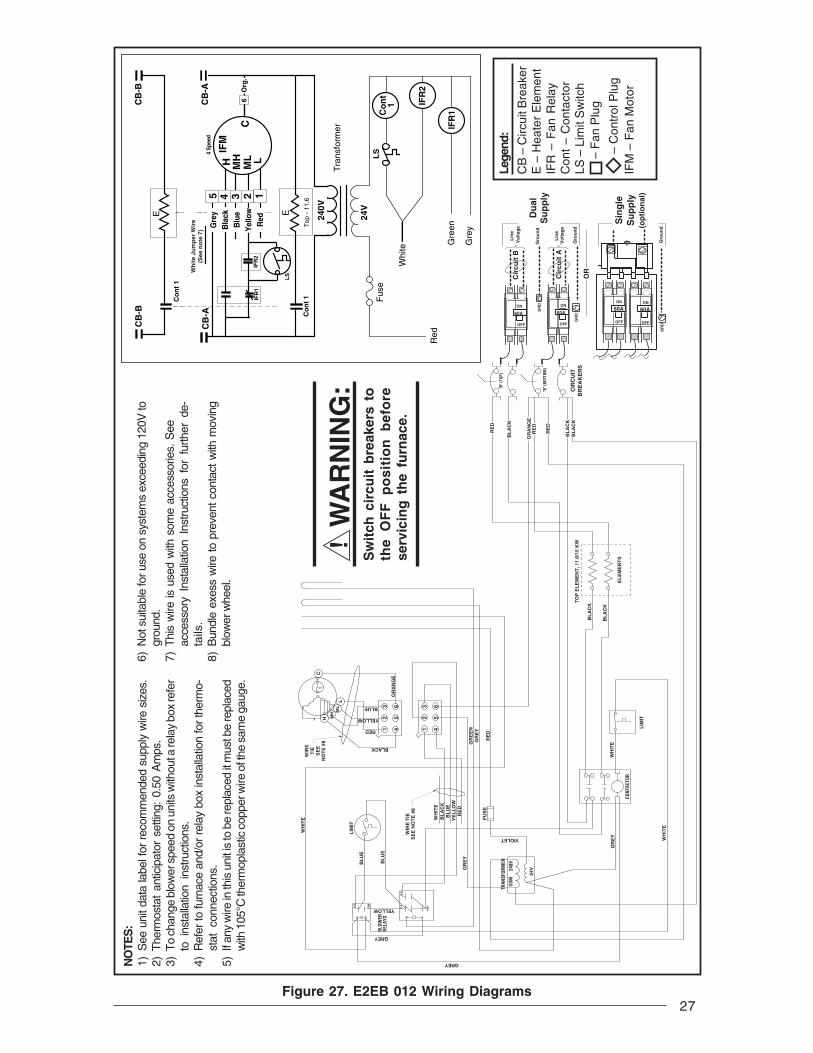
Lege
nd:
CB
– C
ircui
t Bre
aker
E –
Hea
ter
Ele
men
tIF
R –
Fan
Rel
ayC
ont
– C
onta
ctor
LS –
Lim
it S
witc
h –
Fan
Plu
g
– C
ontr
ol P
lug
IFM
– F
an M
otor
240V
Co
nt
1
Tra
nsfo
rmer
Top
- 1
0.0
EC
on
t 1
24V
Red
Whi
te
IFR
1G
reen
Gre
y
Fus
eC
on
t1
LS
IFR
2
CB
-A
CB
-A Org
.6
Wh
ite
Jum
per
Wir
e(S
ee n
ote
7)
IFR
2
Gre
y
Bla
ck
Blu
e
Yel
low
Red
2345 1M
LC
IFM
H MH L4 S
peed
IFR
1
LS
BL
AC
K
BL
AC
K
LIM
IT
WH
ITE
CO
NT
AC
TO
R
WH
ITE
GR
EY
24V
TR
AN
SF
OR
ME
RC
OM
24
0V
FU
SE
WH
ITE
WIR
E T
IES
EE
NO
TE
#8
RE
DY
EL
LO
WB
LU
EB
LA
CK
GR
EYBL
AC
K
GREY
BLOW
ERRE
LAYS
YELLOW
COM
.
N.O.
BL
UE
BL
UE
GREY
COM
N.O.
N.C.
GR
EY
GR
EE
N
RE
D
BLACK
RED
YELLOW
BLUE
WIR
E T
IES
EE
NO
TE
#8
OR
AN
GE
CH M
HM
LL
LIM
IT
WH
ITE
CIR
CU
IT
BR
EA
KE
RS
"A" (
BOTT
OM)
60A
ON
OFF
Cir
cuit
AL
ine
Vo
ltag
e
GR
DG
rou
nd
Su
pp
lyO
RA
NG
E
RE
D
RED
REDB
LA
CK
BLACK
BL
AC
K
EL
EM
EN
TS
TO
P E
LE
ME
NT
S, 1
0.0
KW
12
3
45
6
12
3
45
6
27
! W
AR
NIN
G:
Sw
itch
cir
cuit
bre
aker
s to
the
OF
F p
osi
tio
n b
efo
rese
rvic
ing
th
e fu
rnac
e.
Figure 27. E2EB 012 Wiring Diagrams
NO
TES
:1)
See
uni
t dat
a la
bel f
or r
ecom
men
ded
supp
ly w
ire s
izes
.2)
The
rmos
tat
antic
ipat
or s
ettin
g: 0
.50
Am
ps.
3)T
o ch
ange
blo
wer
spe
ed o
n un
its w
ithou
t a re
lay
box
refe
rto
ins
talla
tion
inst
ruct
ions
.4)
Ref
er to
furn
ace
and/
or r
elay
box
inst
alla
tion
for
ther
mo-
stat
con
nect
ions
.5)
If an
y w
ire in
this
uni
t is
to b
e re
plac
ed it
mus
t be
repl
aced
with
105
°C th
erm
opla
stic
cop
per w
ire o
f the
sam
e ga
uge.
6)N
ot s
uita
ble
for u
se o
n sy
stem
s ex
ceed
ing
120V
togr
ound
.7)
Thi
s w
ire is
use
d w
ith s
ome
acce
ssor
ies.
See
acce
ssor
y In
stal
latio
n In
stru
ctio
ns f
or f
urth
er d
e-ta
ils.
8)B
undl
e ex
ess
wire
to p
reve
nt c
onta
ct w
ith m
ovin
gbl
ower
whe
el.
IFR
1Co
nt
1
LS
IFR
2
240V
Co
nt
1
CB
-A
CB
-BC
B-B
Tra
nsfo
rmer
Top
- 1
1.6
E 24V
Red
Whi
te
Gre
en
Gre
y
E
Fus
e
CB
-A
Wh
ite
Jum
per
Wir
e(S
ee n
ote
7)
6O
rg.
4 S
peed
Co
nt
1
2345 1M
LC
IFM
H MH L
IFR
2
LS
Gre
yB
lack
Blu
eY
ello
wR
edIF
R1
LIM
IT
BLOW
ERRE
LAYS
YELLOW
RE
D
GR
EY
GR
EE
N
OR
AN
GE
BLACKW
HIT
E
RE
D
BL
AC
K
OR
AN
GE
RE
D
RE
D
BL
AC
KB
LA
CK
CIR
CU
IT
BR
EA
KE
RS
"B" (
TOP)
"A" (
BOTT
OM)
BL
AC
K
BL
AC
K
TO
P E
LE
ME
NT
, 11.
6/15
KW
EL
EM
EN
TS
WH
ITE
LIM
IT
GR
EY
CONT
ACTO
R
WH
ITE
VIOLET
TRAN
SFOR
MER
240V
24V
COM
GREY
WIR
E T
IES
EE
NO
TE
#8
FU
SE
GR
EY
BL
AC
KB
LU
EY
EL
LO
WR
ED
WH
ITE
COM
N.O.
N.C.
N.O.
COM
GREY
BL
UE
BL
UE
WIR
ET
IES
EE
NO
TE
#8
CH M
HM
LL
12
3
45
6
12
3
45
6
RED
YELLOW
BLUE
60A
ON
OFF
GR
D
Sin
gle
Su
pp
ly
OR
Cir
cuit
A
Cir
cuit
B
GR
D
GR
D
Gro
un
d
Du
al
Su
pp
ly
(op
tio
nal
)
60A60AONON
OFF OFF
Lin
eV
olt
age
Gro
un
d
Lin
eV
olt
age
60A
ON
OFF
Gro
un
d
Lege
nd:
CB
– C
ircui
t Bre
aker
E –
Hea
ter
Ele
men
tIF
R –
Fan
Rel
ayC
ont
– C
onta
ctor
LS –
Lim
it S
witc
h –
Fan
Plu
g
– C
ontr
ol P
lug
IFM
– F
an M
otor

28
! W
AR
NIN
G:
Sw
itch
cir
cuit
bre
aker
s to
the
OF
F p
osi
tio
n b
efo
rese
rvic
ing
th
e fu
rnac
e.
Figure 28. E2EB 015 Wiring Diagrams
NO
TES
:1)
See
uni
t dat
a la
bel f
or r
ecom
men
ded
supp
ly w
ire s
izes
.2)
The
rmos
tat
antic
ipat
or s
ettin
g: 0
.50
Am
ps.
3)T
o ch
ange
blo
wer
spe
ed o
n un
its w
ithou
t a re
lay
box
refe
rto
ins
talla
tion
inst
ruct
ions
.4)
Ref
er to
furn
ace
and/
or r
elay
box
inst
alla
tion
for
ther
mo-
stat
con
nect
ions
.5)
If an
y w
ire in
this
uni
t is
to b
e re
plac
ed it
mus
t be
repl
aced
with
105
°C th
erm
opla
stic
cop
per w
ire o
f the
sam
e ga
uge.
6)N
ot s
uita
ble
for u
se o
n sy
stem
s ex
ceed
ing
120V
togr
ound
.7)
Thi
s w
ire is
use
d w
ith s
ome
acce
ssor
ies.
See
acce
ssor
y In
stal
latio
n In
stru
ctio
ns f
or f
urth
er d
e-ta
ils.
8)B
undl
e ex
ess
wire
to p
reve
nt c
onta
ct w
ith m
ovin
gbl
ower
whe
el. Le
gend
:
CB
– C
ircui
t Bre
aker
E –
Hea
ter E
lem
ent
IFR
– F
an R
elay
Con
t – C
onta
ctor
LS –
Lim
it S
witc
h –
Fan
Plu
g
– C
ontr
ol P
lug
IFM
– F
an M
otor
IFR
1Co
nt
1
LS
IFR
2
240V
Co
nt
1
CB
-A
CB
-BC
B-B
Tra
nsfo
rmer
Top
- 1
5.0
E 24V
Red
Whi
te
Gre
en
Gre
y
E
Fus
e
CB
-A
Wh
ite
Jum
per
Wir
e(S
ee n
ote
7)
6O
rg.
4 S
peed
Co
nt
1
Gre
yB
lack
Blu
eY
ello
wR
ed2345 1
ML
C
IFM
H MH L
IFR
2IF
R1
LS
RE
D
BL
AC
K
OR
AN
GE
RE
D
RE
D
BL
AC
KB
LA
CK
CIR
CU
IT
BR
EA
KE
RS
"B" (
TOP)
"A" (
BOTT
OM)
BL
AC
K
BL
AC
K
TO
P E
LE
ME
NT
, 11.
6/15
KW
EL
EM
EN
TS
LIM
IT
WH
ITE
CO
NT
AC
TO
R
WH
ITE
GR
EYVIOLET
TRAN
SFOR
MER
240V
24V
COM
GR
EY
GREY
WIR
E T
IES
EE
NO
TE
#8
FU
SE
BL
AC
KB
LU
EY
EL
LO
WR
ED
WH
ITE
BL
AC
K
LIM
IT
BLOW
ERRE
LAYS
YELLOWCOM
N.O.
N.C.
N.O.
COM
GREY
BL
UE
BL
UE
WIR
ET
IES
EE
NO
TE
#8
OR
AN
GE
BLACKH
MH
ML
L
12
3
45
6
RED
YELLOW
BLUE
C
12
3
45
6
GR
EY
GR
EE
N
RE
D
60A
ON
OFF
GR
D
Sin
gle
Su
pp
ly
OR
Cir
cuit
A
Cir
cuit
B
GR
D
GR
D
Gro
un
d
Du
al
Su
pp
ly
(op
tio
nal
)
60A60AONON
OFF OFF
Lin
eV
olt
age
Gro
un
d
Lin
eV
olt
age
60A
ON
OFF
Gro
un
d
WH
ITE
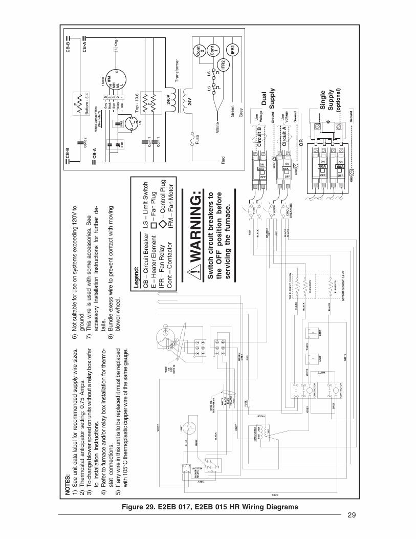
29
! W
AR
NIN
G:
Sw
itch
cir
cuit
bre
aker
s to
the
OF
F p
osi
tio
n b
efo
rese
rvic
ing
th
e fu
rnac
e.
Figure 29. E2EB 017, E2EB 015 HR Wiring Diagrams
NO
TES
:1)
See
uni
t dat
a la
bel f
or r
ecom
men
ded
supp
ly w
ire s
izes
.2)
The
rmos
tat
antic
ipat
or s
ettin
g: 0
.75
Am
ps.
3)T
o ch
ange
blo
wer
spe
ed o
n un
its w
ithou
t a re
lay
box
refe
rto
ins
talla
tion
inst
ruct
ions
.4)
Ref
er to
furn
ace
and/
or r
elay
box
inst
alla
tion
for
ther
mo-
stat
con
nect
ions
.5)
If an
y w
ire in
this
uni
t is
to b
e re
plac
ed it
mus
t be
repl
aced
with
105
°C th
erm
opla
stic
cop
per w
ire o
f the
sam
e ga
uge.
6)N
ot s
uita
ble
for u
se o
n sy
stem
s ex
ceed
ing
120V
togr
ound
.7)
Thi
s w
ire is
use
d w
ith s
ome
acce
ssor
ies.
See
acce
ssor
y In
stal
latio
n In
stru
ctio
ns f
or f
urth
er d
e-ta
ils.
8)B
undl
e ex
ess
wire
to p
reve
nt c
onta
ct w
ith m
ovin
gbl
ower
whe
el.
Lege
nd:
CB
– C
ircui
t Bre
aker
E –
Hea
ter E
lem
ent
IFR
– F
an R
elay
Con
t – C
onta
ctor
LS –
Lim
it S
witc
h –
Fan
Plu
g
– C
ontr
ol P
lug
IFM
– F
an M
otor
CB
-BC
B-B
Bot
tom
- 5
.4C
on
t 2
E
IFR
1
Co
nt
1
LS
IFR
2
Tra
nsfo
rmer
24V
Red
Whi
te
Gre
en
Gre
y
Fus
e
LS
Co
nt
2
240V
Co
nt
1
Top
- 1
0.6
EC
on
t 1
CB
-A
CB
-A Org
.6
Wh
ite
Jum
per
Wir
e(S
ee n
ote
7)
IFR
2
Gre
y
Bla
ck
Blu
e
Yel
low
Red
2345 1M
LC
IFM
H MH L4 S
peed
IFR
1
LS
BL
AC
K
BL
AC
K
TO
P E
LE
ME
NT
, 10.
6 K
W
EL
EM
EN
TS
BO
TT
OM
EL
EM
EN
T, 5
.4 K
W
EL
EM
EN
TS
BL
AC
K
WIR
E T
IES
EE
NO
TE
#8
WIR
ET
IES
EE
NO
TE
#8
LIM
IT
BL
UE
BL
UE
WH
ITE
BL
AC
K
GREY
YELLOW
RE
D
BL
AC
K
OR
AN
GE
RE
D
RE
D
BL
AC
KB
LA
CK
CIR
CU
IT
BR
EA
KE
RS
"B" (
TOP)
"A" (
BOTT
OM)
LIM
IT
WH
ITE
CO
NT
AC
TO
R
WHITE
GR
EY
LIM
IT
WH
ITE
WH
ITE
CO
NT
AC
TO
R
GR
EY
GREY
VIOLET
TRAN
SFOR
MER
240V
24V
COM
GR
EY
FU
SE
BLOW
ERRE
LAYS
COM
N.O.
N.C.
N.O.
COM
BL
AC
KB
LU
EY
EL
LO
WR
ED
WH
ITE
GR
EY
GR
EE
N
RE
D
12
3
45
6
12
3
45
6
HM
HM
LL
C
60A
ON
OFF
GR
D
Sin
gle
Su
pp
ly
OR
Cir
cuit
A
Cir
cuit
B
GR
D
GR
D
Gro
un
d
Du
al
Su
pp
ly
(op
tio
nal
)
60A60AONON
OFF OFF
Lin
eV
olt
age
Gro
un
d
Lin
eV
olt
age
60A
ON
OFF
Gro
un
d

30Figure 30. E2EB 020, 023, and 023 - 5 Ton Wiring Diagrams
CB
-BC
B-B
E
Co
nt
2
Co
nt
2
IFR
1
Co
nt
1
LS
IFR
2
Tra
nsfo
rmer
24V
Red
Whi
te
Gre
en
Gre
y
Fus
e
LS
Co
nt
2
240V
Co
nt
1
Top
- 1
1.6/
10.0
EC
on
t 1
CB
-AC
B-A O
rg.
6
Wh
ite
Jum
per
Wir
e(S
ee n
ote
7)
IFR
2
Gre
y
Bla
ck
Blu
e
Yel
low
Red
2345 1M
LC
IFM
H MH L4 S
peed
IFR
1
LS
Bot
tom
10.
0
! W
AR
NIN
G:
Sw
itch
cir
cuit
bre
aker
s to
the
OF
F p
osi
tio
n b
efo
rese
rvic
ing
th
e fu
rnac
e.
NO
TES
:1)
See
uni
t dat
a la
bel f
or r
ecom
men
ded
supp
ly w
ire s
izes
.2)
The
rmos
tat
antic
ipat
or s
ettin
g: 0
.50
Am
ps.
3)T
o ch
ange
blo
wer
spe
ed o
n un
its w
ithou
t a re
lay
box
refe
rto
ins
talla
tion
inst
ruct
ions
.4)
Ref
er to
furn
ace
and/
or r
elay
box
inst
alla
tion
for
ther
mo-
stat
con
nect
ions
.5)
If an
y w
ire in
this
uni
t is
to b
e re
plac
ed it
mus
t be
repl
aced
with
105
°C th
erm
opla
stic
cop
per w
ire o
f the
sam
e ga
uge.
6)N
ot s
uita
ble
for u
se o
n sy
stem
s ex
ceed
ing
120V
togr
ound
.7)
Thi
s w
ire is
use
d w
ith s
ome
acce
ssor
ies.
See
acce
ssor
y In
stal
latio
n In
stru
ctio
ns f
or f
urth
er d
e-ta
ils.
8)B
undl
e ex
ess
wire
to p
reve
nt c
onta
ct w
ith m
ovin
gbl
ower
whe
el.
Lege
nd:
CB
– C
ircui
t Bre
aker
E –
Hea
ter E
lem
ent
IFR
– F
an R
elay
Con
t – C
onta
ctor
LS –
Lim
it S
witc
h –
Fan
Plu
g
– C
ontr
ol P
lug
IFM
– F
an M
otor
RE
D
BL
AC
K
CIR
CU
IT
BR
EA
KE
RS
"B" (
TOP)
"A" (
BOTT
OM)
LIM
IT
WH
ITE
CO
NT
AC
TO
R
WHITE
GR
EY
LIM
IT
WH
ITE
WH
ITE
CO
NT
AC
TO
R
GR
EY
GREY
VIOLET
TRAN
SFOR
MER
240V
24V
COM
GR
EY
FU
SE
BLOW
ERRE
LAYS
COM
N.O.
N.C.
N.O.
COM
BL
AC
KB
LU
EY
EL
LO
W
RE
D
WH
ITE
12
3
45
6
12
3
45
6
H MH
ML
L
C60A
ON
OFF
GR
D
Sin
gle
Su
pp
ly
OR
Cir
cuit
A
Cir
cuit
B
GR
D
GR
D
Gro
un
d
Du
al
Su
pp
ly
(op
tio
nal
)
60A60AONON
OFF OFF
Lin
eV
olt
age
Gro
un
d
Lin
eV
olt
age
60A
ON
OFF
Gro
un
d
OR
AN
GE
RE
DR
ED
BL
AC
KB
LA
CK
RE
D
BL
AC
K
RE
D
BL
AC
K
BL
AC
K
BL
AC
K
TO
P E
LE
ME
NT
, 10.
0/11
.6 K
W
EL
EM
EN
TS
BO
TT
OM
EL
EM
EN
T, 1
0.0
KW
EL
EM
EN
TS
BL
AC
K
BL
AC
K
GR
EY
GR
EE
EN
RE
D
WIR
ET
IES
EE
NO
TE
#8
WIR
ET
IES
EE
NO
TE
#8
OR
AN
GE
BLACK
BL
AC
K
BL
UE
BL
UE
LIM
IT
GREY
YELLOW
WH
ITE

31
Figure 32. E2 Furnace Low Voltage Wiring if Installed with Platinum Series Models
Typical AC
RGWY
Yellow
BlackPLATINUM
THERMOSTAT
Yellow or BlueWhiteGreenRed
Wire from furnace to Platinum unit
GreenWhiteRedYellow or Blue
Red and white t-stat wireconnected by OEM
Wire from thermostat to furnace
RGWY
GreyWhiteRedGreen
Grey or Green WhiteOrange or RedYellow
FURNACE
PLATINUM
THERMOSTAT
Typical HP
Wire from thermostatto furnace
Yellow or BlueWhiteGreenRed
Wire from furnace toPlatinum unit
GreenWhiteRedYellow or Blue
Platinum installerdisconnectswhite and redt-stat wires
GreyWhiteRedGreen
FURNACE
W Y RC RH G
1 2 3 4 5 6
Wh
ite
Gre
y
Red
Green
W Y R G
1 2 3 4 5 6
Wh
ite
Gre
y
Red
Gre
en
E2EB FURNACE Control Plug(6-pin matrix)
5-Wire Thermostat
W R
1 2 3 4 5 6
Wh
ite
Red
UnstrippedWires
Wirenuts
Gre
y
Gre
en
To A/C To A/C
E2EB FURNACE Control Plug(6-pin matrix)
4-Wire Thermostat
Wirenuts
G R W2 C E O Y
1 2 3 4 5 6
Wh
ite
Gre
y
Red
Gre
en
To H/P
E2EB FURNACE Control Plug(6-pin matrix)
Heat Pump Thermostat
Wirenuts
E2EB FURNACE Control Plug(6-pin matrix)
2-Wire Thermostat
Wirenuts
Figure 31. E2EB Thermostat Connection

O’Fallon, MO
7082360 (Replaces 708172A)
Specifications and illustrations subject to changewithout notice and without incurring obligations.
Printed in U.S.A. (09/03)
INSTALLER: Do Not Discard These Instructions After completing the installation, return these instructions
to the Homeowner’s Package for owner-user’s future reference.Complies with H.U.D. Manufactured Home Construction & Safety Standards.
¢708236/¤7082360
Plenum (Base) ConnectorIs mounting plate secured properly? Yes No N/AIs furnace locked and secured in front? Yes No N/AIs plenum free of debris? Yes No N/AHas plenum opening been reduced in size to accommodate offset? Yes No N/AHas plenum spacer been removed if duct size is large enough? Yes No N/A
TestingIs someone in the plant trained to perform duct tests? Yes No N/A
VentilAire III __ IV __Is VentilAire duct connected properly to furnace? Yes No N/AIs depressurization vent (if required) installed properly? Yes No N/AIs roof assembly installed properly? Yes No N/AIs roof assembly a minimum of 3 inches from any other vents? Yes No N/A
GeneralIs filter in place? Yes No N/AIs owner’s packet included? Yes No N/AChecked storage area for damage to product and proper storage? Yes No N/AIs installation in accordance with installation instructions? Yes No N/A
Comments
Please Write In Appropriate Response
Electrical Wiring (If single circuit, write “N/A” in circuit B)Breaker Size?Furnace Wire Size?Thermostat Wire Size?
Please Circle Appropriate Response
Electrical Is the furnace grounded properly? Yes No N/AIs wiring routed safely with approved connectors? Yes No N/A
Closet Installation Is front clearance a minimum of 6 inches? Yes No N/AIs return air opening a minimum of 235 sq. inches? Yes No N/AIs front clearance less than 6 inches (minimum of 1 inch)? Yes No N/AIs return air opening a minimum of 250 sq. inches? Yes No N/ADoes the furnace have the 5-ton AC coil installed? Yes No N/AIs the return air opening a minimum of 390 sq inches? Yes No N/A
Circuit A Circuit B
Furnace Inspection Report