
1. IntroductionIn a survey conducted by BCA in year 2003 involvingabout 10,000 private residential units, water seepagethrough external walls was found to be a commondefect faced by homeowners. The survey findings alsoshowed that the use of single layer brickwall is themost common cause of water seepage through externalwalls. Almost 90% of the water seepage occurredthrough cracks in the plastered brickwalls. In general,water seepage through external walls occurred withinthe first five years of building completion.
Water seepage through the external walls isunacceptable to the occupants. The problem is furthercompounded by Singapore’s high humidity andabundant rainfall throughout the year. High wind
speeds experienced by high-rise buildings alsoincrease the likelihood of water seepage. Buildingenvelopes must, therefore, be adequately designedand constructed to prevent ingress of water.
There are various external wall systems used in thelocal industry, including precast concrete walls, castin-situ reinforced concrete walls, brickwalls, curtainwalls, cladding walls, concrete block walls, etc.
Due to volume constraint, this publication focuses onprecast concrete walls, cast in-situ reinforced concretewalls and plastered brickwalls. It provides industrygood practices to help achieve durable and effectivewaterproofing of the building envelope.
2. Design of External Walls2.1. GENERAL
The ingress of rainwater impinging on external wallsusually occurs though joints and cracks in the walls.To a lesser extent, seepage through absorption andpermeation may also occur depending on the materialand thickness of the walls.
Watertightness of external walls is usually achieved byusing suitable materials, providing adequate wallthickness, designing proper construction details, aswell as providing surface rendering and finishes whichserve as barrier against water ingress. Where external
walls are exposed to severe weather conditions, moreextensive surface waterproofing should be employed.
This chapter focuses on the design aspects of precastconcrete walls and plastered brickwalls.
2.2. CHOICE OF EXTERNALWALL SYSTEM
The common types of external walls include cast in-situ reinforced concrete (RC) walls, precast concretewalls and masonry brickwalls.
1
intr
oduc
tion/
des
ign
of e
xter
nal w
alls
Figure 2.1: Common types of external wall system
Reinforced Concrete (RC) Wall Precast Concrete Wall Masonry Brickwall

Water seepage usually occurs through the fabric ofbuilding elements or through the gaps between theseelements. For effective watertightness, the wall systemshould be constructed with impervious material andwith minimal joints. Large precast concrete panelsand cast in-situ RC construction with low water cementratio, in general, have better watertightness performancethan brickwalls, which have extensive joints betweenlayers of bricks. In addition, precast walls have manyother benefits over cast in-situ concrete walls andbrickwalls, such as better quality, higher buildabilityand better durability.
Hence, the use of precast concrete walls is stronglyrecommended for external wall construction.
2.3. EXTERNAL PRECAST WALLS
Precast joints are the weakest links in ensuringwatertightness of the external precast concrete walls.
These include joints between precast concrete elements,between precast and cast in-situ elements, as well asbetween precast elements and window/door framesor other fittings. Joint detailing and the use of suitablesealant should, hence, be carefully considered duringthe design stage. Joints with complicated profiles aredifficult to seal and this may affect the watertightnessof the building envelope.
There are two types of joint detailing employed forprecast concrete walls, namely the one-stage joint andtwo-stage joint. One-stage joint is a simple butt jointwith sealant applied against a backer rod at the externalface of the wall. One-stage joint offers only a singleline of defence against water seepage. Pressure dropmay occur across the one-stage joint and water mayseep through micro cracks or hairline cracks. Two-stage joint (Figure 2.2), on the other hand, providestwo defence lines against water ingress. Experience hasshown that two stage joints give better watertightnessperformance than one-stage joints.
desi
gn o
f ext
erna
l wal
ls
2
Figure 2.2: Two-stage joint detailing
Two-stage horizontal joint (Sectional view) Two-stage vertical joint (Plan view)
2.3.1 HORIZONTAL JOINTS
For horizontal joints of precast walls, joggled joints(as shown in Figure 2.3) provide better watertightnessperformance than the butt joints. The matchingupstand and downstand profile of the joggled jointprevents inflow of water through the building envelope.The height of the upstand and downstand is dependenton the exposure conditions, wall thickness and typeof precast wall (load-bearing or non load-bearing). Itgenerally ranges from 35mm for mild exposure to100mm for severe exposure condition.
Figure 2.3 shows the typical details for a horizontaljoggled joint. The joint is sealed with high strengthnon-shrink grout and an approved self-adhesivecompressible waterproofing strip. In addition, anapproved flexible cementitious waterproofingmembrane may be used at the inner corner of theintersection between the wall panel and beam/slabfor enhanced watertightness performance.
Self-adhesivecompressiblewaterproofing strip
Non-shrink grout
INTERNAL EXTERNAL
EXTERNAL
INTERNAL
Sealant
Backer rod
Infill concrete

The gap at the external wall face is usually not sealedto allow incident water in the joint to drain off. If thisgap is also to be sealed (eg. for aesthetic reasons), thejoint can be fully sealed using non-shrink grout, witha backer rod and an appropriate sealant installed atthe exterior end of the joint (Figure 2.4a). Alternatively,the joint can be sealed with non-shrink grout at theinterior end with a sealant installed at the exterior end
of the joint. For such sealing system, the sealant mustbe discontinued at regular intervals (at intersectionswith the vertical joints) to drain off incident waterthat has managed to seep into the gap (Figure 2.4b).
For load bearing walls, the entire horizontal jointmust be sealed, for example, with non-shrink grout(Figure 2.4a).
3
desi
gn o
f ext
erna
l wal
ls
Figure 2.3: Typical sectional view of horizontal joggled joint (for non load-bearing walls)
Approved self-adhesivecompressible waterproofing strip
INTERNAL EXTERNAL
High strength non-shrink grout
Approved flexible cementitiouswaterproofing membrance
15mm100mm
100mm
Typicalstorey level
Cast in-situ beam
Fillet
[A]
[C]
[B]
15mm
Slope 1:10
Precast panel
[A] ≥ 35mm
[B] ≥ 35mm
[B][C] ≤ 1

desi
gn o
f ext
erna
l wal
ls
4
Figure 2.4: Typical sectional view of horizontal joggled joint
a) Fully sealed horizontal joint b) Sealing of external gap (For non load bearing walls)
Joint fully sealed withnon-shrink grout
Backer rod
Sealant
Approved self-adhesivecompressible waterproofing strip
High strengthnon-shrink grout
Backer rod
Sealant must bediscontinued atvertical joints
2.3.2 VERTICAL JOINTS
The two-stage joint detailing is recommended forvertical joints as it provides various water-resistantbarriers. These include a sealant at the outer wall face,a pressure relief space to avoid rain driven penetration,
and an infilled concrete/mortar joint with a sealingstrip at the inner wall face. The seal at the external faceshould be discontinued at intersections with thehorizontal joints to allow draining of incident water.
Figure 2.5: Vertical joint sealed with sealant and infill concrete/mortar joint, with pressure relief space (plan view)
INTERNAL
EXTERNAL
15mm
~ 50mm
Precast panel
Sealant
Backer rod
Pressure relief space
Sealing strip
Airtight seal (infill concreteor mortar joint)
Figure 2.6: Setting back of sealant from the external face of the panel (plan view)
For better protection of the sealant from rain, windand UV light, the sealant may be set back from theexternal face of the wall as shown in Figure 2.6. Thishelps to minimise deterioration of the sealant.
Sealant set back fromexternal face
EXTERNAL

If a sealing strip is to be used with the infillconcrete/mortar joint at the inner wall face as shownin Figure 2.5, its width should be equal to the jointgap plus sufficient overlap (approximately 60mm) oneach side of the joint. The sealing strip should be madeof an elastic material, or alternatively, some slack inthe sealing strip should be provided so that it doesnot tear under repeated stresses at the joint area. Asuitable gasket can also be used in place of the sealingstrip to create an airtight seal at the inner wall face.
Having an abutting cast in-situ concrete column orstiffener behind the joint can further enhancewatertightness of the joint. This type of joint is knownas the ‘wet’ or cast in-situ joint connection, and iseffective in preventing water seepage through theprecast joints. Examples of wet joints are shown inFigure 2.9 to 2.11.
5
desi
gn o
f ext
erna
l wal
ls
Figure 2.7: Dimensions of pressure relief space(plan view)
According to CP 81:1999, the grooves that create thepressure relief space should comply with the followingminimum requirements:
a) Width = 15mmb) Depth = 5mm; andc) Sharp edges.
The grooves that create the pressure relief space shouldbe located as shown in Figure 2.8 below, with thegrooves sloped at an angle not more than 10° fromthe vertical axis.
EXTERNAL
≥ 15mm
≥ 5mm
Groove
Figure 2.8: Typical details of a pressure relief space
INTERNAL EXTERNAL
GrooveFlashing
10°max

desi
gn o
f ext
erna
l wal
ls
6
Figure 2.9: Typical vertical joint with cast in-situ stiffener (plan view)
EXTERNAL
Precast panels
Cast in-situ stiffener(or column)
Backer rods Sealant
Precast panels
Non-shrink cement grout
Bars from precast panels(indicative)
Figure 2.10: Typical details for wet joint between precast panels (plan view)
EXTERNAL
U bar fromprecast panel
Sealant andbacker rod
In-situ lapping bar
Precast façade panel
Starter bar Cast in-situ connection
Figure 2.11: Typical details for corner joint between precast panels (plan view)
EXTERNAL
Sealant and backer rod Dowel bar
Corrugated pipe
Loop bar Lapping bar placed on site
Precast façade panel
Loop bar
Cast in-situ connection
*Note: Rebar details shown in Figure 2.9 to 2.11 are only indicative.Actual rebar detailing must be provided in structural design and drawings.
7
desi
gn o
f ext
erna
l wal
ls
2.3.3 INTERSECTIONS OF HORIZONTALAND VERTICAL JOINTS
Intersections of the horizontal and vertical jointsshould be detailed to contain any incident water withinthe individual floor levels. To achieve this, a flashingcould be installed over a width of at least 120mm oneither side of the vertical joint as shown in Figure 2.12.
Figure 2.12: Intersection of horizontal andvertical joints
EXTERNAL INTERNAL
Flashing
Min120mm
2.3.4 JOINT WIDTH AND DEPTH
Joints between precast wall panels should haveadequate width to accommodate anticipatedmovements of the panels, and to ensure the jointsealant performs within its design capabilities. Whenthe joint gaps are too narrow, adjacent elements maycome into contact and be subject to undesired loading,distortion and cracks. A good practice is to provide ajoint gap of 12mm – 20mm to ensure properapplication of sealants.
Joint depth is also an important factor as failures oftenoccur because the sealant depth is either too thick(cohesion failure, unable to stretch sufficiently) or toothin (adhesion failure, insufficient bonding to sidesof substrates) to function as intended.
The depth of sealant depends on the type andconditions of service. Elasto-plastic sealants are usuallyapplied such that the depth is half the width formaximum movement accommodation and elasticsealants perform best in thin sections. CP 81:1999
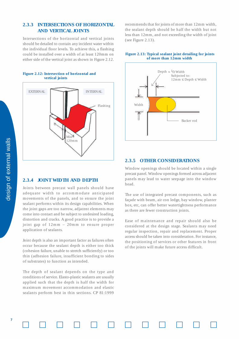
recommends that for joints of more than 12mm width,the sealant depth should be half the width but notless than 12mm, and not exceeding the width of joint(see Figure 2.13).
2.3.5 OTHER CONSIDERATIONS
Window openings should be located within a singleprecast panel. Window openings formed across adjacentpanels may lead to water seepage into the windowhead.
The use of integrated precast components, such asfaçade with beam, air con ledge, bay window, planterbox, etc, can offer better watertightness performanceas there are fewer construction joints.
Ease of maintenance and repair should also beconsidered at the design stage. Sealants may needregular inspection, repair and replacement. Properaccess should be taken into consideration. For instance,the positioning of services or other features in frontof the joints will make future access difficult.
Figure 2.13: Typical sealant joint detailing for joints of more than 12mm width
Width
Depth
Backer rod
1/2 WidthSubjected to:12mm ≤ Depth ≤ Width

desi
gn o
f ext
erna
l wal
ls
8
Figure 2.14: Location of window openings
Window frame located within a single panel Window frame across adjacent panels
Window openings
Precast panels
✓ ✗
Figure 2.15: Examples of integrated precast components
Façade and beam Façade and air con ledge Façade and bay window
2.4 EXTERNAL MASONRY BRICKWALLS
In general, external brickwalls have inferiorwatertightness performance than precast concrete wallsand cast in-situ RC walls. The quality of the erectedbrickwalls is highly workmanship-dependent.
Due to its inferior watertightness performance,brickworks are not encouraged for use in theconstruction of external walls. Where the Designerdecides to use external brickwalls for the project, thefollowing good practices on designs of external
brickwalls should be adopted to achieve the requiredwatertightness performance.
2.4.1 WALL THICKNESS
Half-brick thick walls have inferior waterproofingperformance compared to full-brick thick walls. Hence,where brickworks are used for external wallconstruction, full-brick thick walls with English bondinstead of half-brick thick walls with Stretcher bondshould be adopted.

9
desi
gn o
f ext
erna
l wal
ls
Figure 2.16: Full-brick thick brickwall with English Bond
Closer
Header
Stretcher
2.4.2 COMPOSITION OF MORTARJOINTS
Cement mortar joints are relatively more porous andare, hence, more susceptible to water seepage than thebrick units. The type of mortar bedding selected canhave a considerable effect on its bonding strength andworkability, which in turn affects the watertightnessof the joints.
2.4.3 PROVISION OF SURFACE FINISHES
Rendered brickwalls give better rain resistance thanfair-faced brickwalls. It is, however, essential to selectthe appropriate mix ratio, thickness and number ofcoats to minimise cracks in the rendering.
2.4.4 PROVISION OF CONCRETE KERBS
Concrete kerbs of at least 100mm height should beprovided for external brickwalls to enhance theirwatertightness. As a good practice, these kerbs shouldbe provided at every storey. This is especially importantwhere there is a RC recess or a RC ledge at the beam/floor level.
Figure 2.17: Applying rendering to an external brickwall
Figure 2.18: Concrete kerb at the base of brickwall

2.4.5 DAMP-PROOF COURSE (DPC)
Ground water can penetrate the building fabric, risingvertically through capillary action. Damp-proof course(DPC) should be provided in masonry walls to guardagainst such ground moisture. To protect against
rainwater bouncing off the ground and splashing ontothe wall, the DPC should be installed at a minimum150mm height above the surrounding finishedfloor level.
desi
gn o
f ext
erna
l wal
ls
10
Min
150
mm
Externalbrickwall
DPC
Concretekerb
Figure 2.19: Installation of DPC
INTERNALEXTERNAL
Finished floor level
2.4.6 JOINTS BETWEEN DISSIMILARMATERIALS
Where the brickwall abuts a concrete member, bondingbars should be provided at the joints to minimisecracks at these locations. These bonding bars shouldbe secured to the concrete member. Alternatively, thesebars could be cast together with the concrete member.
Some bonding bar systems come with a lipped framethat is fastened to the concrete member. The lippedframe allows greater flexibility in positioning the
bonding bars to facilitate brick-laying. The bondingbars should be of minimum 200mm length andinstalled at every 4th course of the brickwalls.
A layer of mesh reinforcement should be provided atthe interfaces between dissimilar materials, for examplebetween brick and concrete members. The meshreinforcement helps to distribute stress and preventplaster crack at these locations.

11
desi
gn o
f ext
erna
l wal
ls
2.4.7 MESH REINFORCEMENT INMORTAR JOINTS
To provide additional resistance to stresses, vibrationand thermal movement, mesh reinforcement shouldbe embedded in the mortar joints between courses ofbrickwork. The mesh reinforcement should be laidover the 1st or 2nd course and at every subsequent4th course of brickwork. There should be minimum150mm lapping where different sections of meshreinforcement overlap.
Figure 2.21: Mesh reinforcement embedded at every 4th course
Mesh reinforcement at interfacebetween brickwall and RC column (plan view)
Mesh reinforcement at interfacebetween brickwall and RC column
INTERNAL
EXTERNALExternal plasterMesh reinforcement
Brick
RC column
Figure 2.20: Joints between brick and RC members
Bonding bar system without a lipped frame
Bonding barsfor full-brickthick walls
Lipped frame
Bonding bar
Bonding bars with lipped frame system

desi
gn o
f ext
erna
l wal
ls
12
2.4.8 STIFFENERS AND MOVEMENT JOINTS
Vertical and horizontal stiffeners should be provided for big panels of brickwork. Consult the structural Engineerfor details of the stiffeners. Where brickwalls abut the stiffeners, steel bonding ties should be provided at every4th course.
Figure 2.22: Example of a vertical RC stiffener for walls Figure 2.23: Typical stiffener details
RC stiffener
RC column
RC kerbRebar with links
Rebar starters atevery 4th course
Vertical movement joints of about 12mm width should be provided in brickwork at maximum 6m intervals.Joints should be filled with a suitable material, such as polyethylene strip or urethane sealant.
Figure 2.24: Vertical movement joints
Joint sealant
2.5 OTHER DESIGN CONSIDERATIONS
2.5.1 EXTERNAL BUILDING FEATURES
External features such as bay windows, air conditioningledges and planter boxes are increasingly being usedin building projects. For such features, the followingprovisions should be considered:
• overhangs protruding minimum 300mm out ofthe building envelope help to shield the externalwalls (especially brickwalls) from direct rainfall;
• overhangs also help to shield wall openings (suchas window openings or M&E openings) from directrainfall;
• adequate fall along protruding features to avoidaccumulation of stagnant water at the corner joints;and
• drips provided at the underside of external featuresto prevent water flow towards the external walls.

13
desi
gn o
f ext
erna
l wal
ls
Figure 2.25: External brickwall with overhang
INTERNALEXTERNAL
External brickwall
Typical storey floor level
Typical storey floor level
300mm protrusion
Figure 2.26: Provision of overhang
M&E opening
Overhang helps toshield wall openings
Window opening
Figure 2.27: Provision of drip at underside of external features
Drip linesprovided both
above and belowthe bay window
25mm ~ 15mm
10m
m
Drip
Slope downwards

desi
gn o
f ext
erna
l wal
ls
14
2.5.2 M&E SERVICES
Chasing of external walls for embedding M&E servicesreduces the effective thickness of the walls and weakensthe physical barrier against water ingress. Designersshould avoid running M&E services along externalwalls, especially external brickwalls.
For RC walls, recess for embedding M&E servicesshould be provided during the concrete casting stage.Hacking of walls should be avoided. The effectivethickness of RC walls should be maintained at aminimum of 80mm.
Figure 2.28: Recess provided in RC wall during concrete casting
Recess for M&E service
Recess for embeddingM&E services
Min80mm
RC Wall
Plan view
Figure 2.29: M&E services that penetrate the external walls
Housing M&E services in trunking box (View from inside) Housing M&E services in trunking box (View from outside)
Services that penetrate the external walls should behoused within trunking boxes. All gaps between thetrunking boxes and the external walls must becompletely sealed to ensure watertightness at these
penetrations. The penetration points should, wherepossible, be situated below an overhang element,as shown in Figure 2.26.

15
desi
gn o
f ext
erna
l wal
ls
2.5.3 WATERPROOFING APPLICATIONALONG PERIMETER WALLS ANDPLANTERS
A layer of waterproofing membrane should beapplied to the perimeter walls with an upturn ofminimum 300mm along the external walls, as shownin Figure 2.30. For external walls with surrounding
planters (eg. environment decks), the requiredupturn of 300mm should be measured from thefinished soil level.
For external walls designed with surroundingconcrete planter box, it is a good practice to applywaterproofing membrane over the entire interior ofthe planter box, as shown in Figure 2.31.
Figure 2.30: Waterproofing application along perimeter walls and planters
INTERNALEXTERNAL
300mm upturn(from apron slab orfinished soil level)
Waterproofingmembrane
25 x 25 fillet
External wall
Figure 2.31: Planter box
Waterproofing membraneshould be applied to theentire interior of the planterbox (area A), with an upturnalong the top ledge (area B).
EXTERNAL WALL
B A
Planter box


