100% DESIGN
THERMALLY ENHANCED SOIL VAPOR EXTRACTION SYSTEM
AT FORMER CHLOROBENZENE PROCESS AREA
W.G. KRUMMRICH FACILITY
SAUGET, ILLINOIS
Prepared For:
SOLUTIA INC. 575 Maryville Centre Drive
St. Louis, MO 63141
Prepared By:
XDD, LLC 22 Marin Way
Stratham, New Hampshire 03885 Tel: (603) 778-1100 Fax: (603) 778-2121
November 2011
100% Design - Thermally Enhanced Soil Vapor Extraction System W.G. Krummrich Facility, Sauget, IL
November 2011 Page i
TABLE OF CONTENTS
1.0 INTRODUCTION............................................................................................................. 1
1.1 SUMMARY OF REMEDIATION APPROACH .................................................................................... 2
1.2 REMEDIATION OBJECTIVES ......................................................................................................... 3
1.3 ALTERNATIVE TECHNOLOGY SELECTION ................................................................................... 5
2.0 SITE BACKGROUND INFORMATION ...................................................................... 6
2.1 TREATMENT AREA CHARACTERIZATION .................................................................................... 7
2.2 CONTAMINANTS OF CONCERN ..................................................................................................... 8
2.2.1 Maximum Soil Concentrations ................................................................................................ 8
2.2.2 Mass Estimates ........................................................................................................................ 8
2.3 GEOLOGY AND HYDROGEOLOGY ................................................................................................ 9
2.3.1 Geological Cross-Sections .................................................................................................... 10
2.3.2 Groundwater Level Trends.................................................................................................... 10
3.0 T-SVE DESIGN BASIS .................................................................................................. 12
3.1 DESCRIPTION OF T-SVE TECHNOLOGY ..................................................................................... 12
3.2 SVE/AI CONCEPTUAL DESIGN BASIS........................................................................................ 13
3.3 SOIL HEATING MODEL .............................................................................................................. 15
4.0 SYSTEM DESIGN OVERVIEW .................................................................................. 17
4.1 OVERVIEW OF PROCESS FLOW .................................................................................................. 17
4.2 SYSTEM CONTROLS ................................................................................................................... 20
4.3 SYSTEM CAPACITY AND WELL FIELD FLOW DISTRIBUTION ..................................................... 22
4.4 GENERAL DESIGN CONSIDERATIONS ........................................................................................ 23
4.5 APPLICABLE CONSTRUCTION AND SAFETY STANDARDS .......................................................... 23
5.0 WELL LAYOUT AND CONSTRUCTION DETAILS............................................... 25
5.1 T-SVE WELL AND VAPOR PROBE LAYOUTS ............................................................................. 25
5.2 WELL CONSTRUCTION DETAILS ................................................................................................ 26
5.2.1 T-SVE Well Construction Details .......................................................................................... 26

100% Design - Thermally Enhanced Soil Vapor Extraction System W.G. Krummrich Facility, Sauget, IL
November 2011 Page ii
5.2.2 Vapor Probe Construction Details ........................................................................................ 27
5.2.3 Well Surface Completions ..................................................................................................... 28
5.3 GEOLOGICAL CHARACTERIZATION ........................................................................................... 28
5.4 WELL DEVELOPMENT ................................................................................................................ 28
5.5 WELL INSTALLATION LOGISTICS ............................................................................................... 29
5.5.1 Utility Clearance ................................................................................................................... 29
5.5.2 Pre- and Post-Drilling Surveying ......................................................................................... 29
5.6 DECONTAMINATION AND WASTE HANDLING/DISPOSAL .......................................................... 29
5.6.1 Equipment Decontamination and Decontamination Areas ................................................... 29
5.6.2 Waste Accumulation Areas and Waste Handling .................................................................. 30
6.0 MANIFOLD PIPING DESIGN ..................................................................................... 33
6.1 SVE AND AI MANIFOLD DESIGN ............................................................................................... 33
6.1.1 General Material Compatibility Specifications .................................................................... 34
6.1.2 General Fitting Assembly Specifications .............................................................................. 35
6.1.3 Manifold Pressure Testing Requirements ............................................................................. 36
6.2 PIPE SUPPORTS ........................................................................................................................... 36
6.2.1 Support Load Capacity ......................................................................................................... 37
6.2.2 Pipe Support Spacing ............................................................................................................ 38
6.2.3 Pipe Saddles and Roller Supports ......................................................................................... 39
6.3 MANIFOLD PIPING DETAILS ....................................................................................................... 39
6.3.1 Expansion/Flex Joints ........................................................................................................... 39
6.3.2 Cleanouts and Sumps ............................................................................................................ 40
6.3.3 Condensate Handling System ................................................................................................ 40
6.4 WINTERIZATION ........................................................................................................................ 40
7.0 WELLHEAD CONSTRUCTION DETAILS ............................................................... 41
7.1 SVE AND SVE/AI WELLHEAD DESIGN ..................................................................................... 41
7.1.1 General Material Compatibility Specifications .................................................................... 42
7.1.2 Fitting Assembly Specifications ............................................................................................ 42
7.1.3 Pressure Testing Requirements ............................................................................................. 44
7.2 WINTERIZATION ........................................................................................................................ 44
100% Design - Thermally Enhanced Soil Vapor Extraction System W.G. Krummrich Facility, Sauget, IL
November 2011 Page iii
8.0 PIPING HEAT TRACE AND INSULATION ............................................................. 45
8.1.1 Heat Trace ............................................................................................................................. 45
8.1.2 Pipe Insulation ...................................................................................................................... 46
9.0 T-SVE SYSTEM DESIGN AND SPECIFICATIONS ................................................ 47
9.1 SVE SYSTEM EQUIPMENT ......................................................................................................... 48
9.2 SVE CONDENSATE HANDLING SYSTEM .................................................................................... 50
9.2.1 Air Moisture Separators ........................................................................................................ 50
9.2.2 Oil Water Separator .............................................................................................................. 51
9.2.3 Equalization Tank ................................................................................................................. 51
9.2.4 Air Stripper Unit ................................................................................................................... 52
9.2.5 NAPL Storage Drum ............................................................................................................. 52
9.2.6 Carbon Filter Ventilation System .......................................................................................... 53
9.3 AI SYSTEM EQUIPMENT ............................................................................................................. 53
9.4 SYSTEM INSTRUMENTATION ...................................................................................................... 55
9.4.1 Manual Read Instrumentation ............................................................................................... 55
9.4.2 Analog/Digital Instrumentation ............................................................................................ 56
9.4.3 Automation Controls ............................................................................................................. 57
9.5 MATERIAL COMPATIBILITY AND ASSEMBLY SPECIFICATIONS ................................................. 58
9.5.1 Materials of Construction ..................................................................................................... 58
9.5.2 Assembly Specifications ........................................................................................................ 59
10.0 PROGRAMMABLE LOGIC CONTROLLER AND INTERLOCKS ...................... 61
10.1 SYSTEM CONTROL SPECIFICATIONS .......................................................................................... 61
10.1.1 Programmable Logic Controller ...................................................................................... 61
10.1.2 Graphical User Interface and Remote Telemetry System ................................................. 62
10.1.3 Autodialer ......................................................................................................................... 62
10.1.4 Emergency Stop Buttons ................................................................................................... 63
10.1.5 Thermal Oxidizer LEL Meter ............................................................................................ 63
10.1.6 Building VOC Monitor and Seismic Monitor ................................................................... 63
10.1.7 Audio/Visual Alarm Beacons ............................................................................................ 63
10.1.8 Oxygen Sensors ................................................................................................................. 64
100% Design - Thermally Enhanced Soil Vapor Extraction System W.G. Krummrich Facility, Sauget, IL
November 2011 Page iv
10.1.9 Vapor Probe Temperature Sensors ................................................................................... 64
10.1.10 Water Level Transducers .................................................................................................. 64
10.1.11 Dissolved Oxygen Probes/Data Loggers .......................................................................... 65
10.2 PROCESS CONTROL STANDARDS ............................................................................................... 65
11.0 VAPOR TREATMENT SYSTEM SPECIFICATIONS ............................................. 67
11.1 THERMOX SYSTEM .................................................................................................................... 67
11.2 ACID GAS SCRUBBER ................................................................................................................ 68
12.0 EQUIPMENT BUILDING ............................................................................................. 70
12.1 EQUIPMENT BUILDING AND EQUIPMENT LAYOUT .................................................................... 70
12.1.1 Electrical Specifications ................................................................................................... 71
12.1.2 Ventilation Specifications ................................................................................................. 72
12.1.3 Enclosure Noise Requirements ......................................................................................... 72
12.1.4 Emergency Eyewash Station ............................................................................................. 73
12.1.5 Fire Extinguishers and First Aid Kits ............................................................................... 73
13.0 INSULATING CONCRETE SURFACE COVER ...................................................... 74
13.1 SITE GRADING ........................................................................................................................... 74
13.2 CONCRETE SURFACE COVER ..................................................................................................... 74
14.0 ELECTRICAL DESIGN ................................................................................................ 75
14.1 ELECTRICAL SYSTEM DETAILS .................................................................................................. 75
14.1.1 Main Power and Sub-Panel Layout .................................................................................. 75
14.1.2 Sensors and Interlocks Wiring Diagram ........................................................................... 75
14.1.3 Miscellaneous Electrical Connections .............................................................................. 76
15.0 UTILITY SPECIFICATIONS ....................................................................................... 77
15.1 UTILITY CONNECTIONS ............................................................................................................. 77
15.1.1 Fire Protection Water System ........................................................................................... 77
15.1.2 Natural Gas Line Details .................................................................................................. 77
15.1.3 Sewer Line Details ............................................................................................................ 78
15.1.4 Water Line Details ............................................................................................................ 79
15.1.5 Steam Line Details ............................................................................................................ 79
100% Design - Thermally Enhanced Soil Vapor Extraction System W.G. Krummrich Facility, Sauget, IL
November 2011 Page v
15.2 PRESSURE TESTING REQUIREMENTS ......................................................................................... 79
15.3 BARRICADES .............................................................................................................................. 80
16.0 IMPLEMENTATION TASKS ...................................................................................... 81
16.1 PERMITTING ............................................................................................................................... 81
16.1.1 Air Quality Construction Permit and Air Quality Operating Permit ............................... 81
16.1.2 Water Discharge Permit ................................................................................................... 81
16.1.3 Underground Injection Control Notification .................................................................... 81
16.2 DESIGN AND PROJECT OPERATIONS PLANS............................................................................... 81
16.2.1 Health and Safety Plan ..................................................................................................... 82
16.2.2 Operations, Maintenance, and Monitoring Manual ......................................................... 82
16.2.3 Sampling and Analysis and Quality Assurance Project Plans ......................................... 82
16.2.4 Spill Prevention, Control, and Countermeasure Plan ...................................................... 82
16.3 MOBILIZATION ........................................................................................................................... 83
16.4 SITE SECURITY ........................................................................................................................... 83
16.5 WELL INSTALLATION................................................................................................................. 83
16.6 INSULATING CAP INSTALLATION ............................................................................................... 84
16.7 MANIFOLD INSTALLATION ........................................................................................................ 84
16.8 EQUIPMENT INSTALLATION ....................................................................................................... 84
16.9 SYSTEM START-UP/EQUIPMENT SHAKEDOWN .......................................................................... 85
16.10 SYSTEM OPERATION .................................................................................................................. 85
16.11 SYSTEM DEMOBILIZATION ........................................................................................................ 85
17.0 OPERATION AND MONITORING ............................................................................ 87
17.1 GENERAL SYSTEM MONITORING ............................................................................................... 87
17.1.1 Process Monitoring ........................................................................................................... 87
17.1.2 Performance Monitoring .................................................................................................. 88
17.1.3 Compliance Monitoring .................................................................................................... 88
17.1.4 Groundwater Level Monitoring ........................................................................................ 88
17.2 WELL FIELD OPTIMIZATION ...................................................................................................... 89
17.3 SOIL SAMPLING ......................................................................................................................... 90
17.3.1 Baseline Soil Sampling ..................................................................................................... 90
17.3.2 Interim Soil Sampling ....................................................................................................... 90
100% Design - Thermally Enhanced Soil Vapor Extraction System W.G. Krummrich Facility, Sauget, IL
November 2011 Page vi
17.3.3 Final Soil Sampling .......................................................................................................... 90
17.4 DATA EVALUATION ................................................................................................................... 91
17.5 STATUS REPORTING ................................................................................................................... 91
17.6 T-SVE SHUTDOWN PROTOCOL ................................................................................................. 92
17.7 TRANSITION TO BIOVENTING .................................................................................................... 94
18.0 SCHEDULE..................................................................................................................... 95
FIGURES
Figure 1 Site Plan and Drawing Index
Figure 2 T-SVE Treatment Area
Figure 3 Geological Cross-Section A-A’
Figure 4 Geological Cross-Section B-B’
Figure 5 Geological Cross-Section C-C’
Figure 6 SVE/AI System Process Flow Diagram
Figure 7 T-SVE Well Locations
Figure 8 T-SVE Well Construction Diagram
Figure 9 Vapor Probe Construction Diagram
Figure 10 SVE Piping Layout
Figure 11 AI Piping Layout
Figure 12 Pipe Supports
Figure 13 Expansion Joints/Flex Joints
Figure 14 Cleanouts and Sumps
Figure 15 Steam Traps/Condensate Drains
Figure 16 SVE and SVE/AI Wellhead Details
Figure 17 Piping Heat Trace
Figure 18 SVE Piping and Instrumentation Diagram
Figure 19 AI Piping and Instrumentation Diagram
100% Design - Thermally Enhanced Soil Vapor Extraction System W.G. Krummrich Facility, Sauget, IL
November 2011 Page vii
FIGURES (Continued)
Figure 20 Electrical Details – Sensors and Interlocks Wiring
Figure 21 Temperature Probe and Water Level Transducer Locations
Figure 22 ThermOx Piping and Instrumentation Diagram
Figure 23 Acid Gas Scrubber Piping and Instrumentation Diagram
Figure 24 Equipment Building Layout
Figure 25 Insulating Cap
Figure 26 Electrical Utilities Layout
Figure 27 Electrical Details – Main Power and Sub-Panel Layout
Figure 28 Electrical Details – Electrical Line Diagram
Figure 29 Fire Protection Utilities Map
Figure 30 Natural Gas Supply Line Connection
Figure 31 Natural Gas Supply Line Details
Figure 32 Sewer Discharge Line Connection
Figure 33 Sewer Discharge Line Details
Figure 34 Water Supply Line Connection
Figure 35 Water Supply Line Details
Figure 36 Steam Supply Line Connection
Figure 37 Steam Supply Line Details
Figure 38A CPA Design & Construction Schedule
Figure 38B T-SVE Operation Schedule
100% Design - Thermally Enhanced Soil Vapor Extraction System W.G. Krummrich Facility, Sauget, IL
November 2011 Page viii
TABLES
Table 1 Maximum Soil COC Concentrations
Table 2 Contaminant Mass Estimates
Table 3 SHU and DHU Monitoring Well Gauging Information
Table 4 T-SVE Well and Vapor Probe General Design Parameters
Table 5 T-SVE System General Operating Parameters
Table 6 T-SVE Well Construction Details
Table 7 Vapor Probe Construction Details
Table 8 T-SVE Wells and Vapor Probe Materials List
Table 9 Summary of Exterior Headlosses in SVE and AI Piping
Table 10 Manifold Piping Specifications and Materials List
Table 11 T-SVE System Piping Pressure Testing Requirements
Table 12 SVE System Specifications
Table 13 AI System Specifications
Table 14 Summary of SVE and AI Input-Output Schedule
Table 15 General System Control Specifications
Table 16 ThermOx System Specifications
Table 17 General Specifications
Table 18 Electrical Load Summary Table
LIST OF APPENDICES
Appendix A Contaminant of Concern Chemical Properties
Appendix B Heat Modeling Simulations
Appendix C T-SVE Shutdown Protocol
100% Design - Thermally Enhanced Soil Vapor Extraction System W.G. Krummrich Facility, Sauget, IL
November 2011 Page ix
Executive Summary
XDD, LLC (XDD) has prepared this design document (100% Design) for Full-Scale Thermally
Enhanced Soil Vapor Extraction for the remediation of unsaturated zone soil impacts at the
former Chlorobenzene Process Area (CPA), at the Solutia Inc. (Solutia) W.G. Krummrich
Facility in Sauget, Illinois (site). This 100% Design contains the design basis for implementation
and schedule for full-scale Thermally Enhanced Soil Vapor Extraction (T-SVE) treatment. A
separate design document has been prepared for the Full-Scale Enhanced Aerobic
Bioremediation (EABR) treatment of the saturated zone impacts in the CPA.
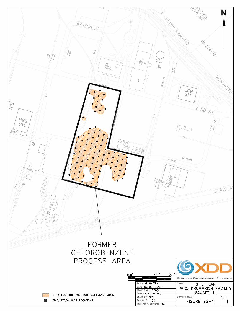
Treatment Areas: The area targeted for T-SVE treatment is an approximately 3.5 acre area
within the CPA. The target treatment area is shown on Figure ES-1. The contaminants of
concern (COCs) are volatile organic compounds (VOCs), primarily monochlorobenzene (MCB),
1,2-dichlorobenzene (1,2-DCB), 1,3-DCB, 1,4-DCB, 1,2,4-trichlorobenzene (1,2,4-TCB), and
benzene. The total COC mass in the target treatment area is estimated at 440,000 pounds (lbs).
Geology and Hydrogeology: The target depth interval for the T-SVE treatment is within the
unsaturated portion of the Shallow Hydrogeologic Unit (SHU), between ground surface and 15
feet below ground surface (feet bgs). The unsaturated zone consists of the three major layers:
Sandy fill/upper silty sand layer: This layer generally extends down from ground surface
to between 4 and 10 feet bgs.
Intermediate silty clay layer: This layer generally ranges in thickness between 4 and 12
feet and the top of this layer is generally encountered at depths ranging from
approximately 4 to 10 feet bgs.
Lower silty sand layer: This layer is encountered below the intermediate silty clay and is
encountered at depths ranging between approximately 10 and 18 feet bgs.

100% Design - Thermally Enhanced Soil Vapor Extraction System W.G. Krummrich Facility, Sauget, IL
November 2011 Page x
Groundwater levels in the treatment areas typically range from 10 feet bgs to greater than 15 feet
bgs. Water levels are directly influenced by the level of the Mississippi River (located
approximately one mile west of the site). Due to fluctuations in groundwater levels, it is
anticipated that portions of the lower silty sand layer will be submerged seasonally.
Overview of T-SVE Design and Operational Strategy: T-SVE will be implemented using a
dual-level SVE and Air Injection (AI) well network (i.e., shallow and deep well screens). The
shallow SVE/AI wells will be designed to target the upper sandy fill/silty sand unit (referred to
as the “shallow” zone). The deep SVE/AI wells are designed to target the lower silty sand unit
below the intermediate silty clay layer and above the water table (referred to as the “deep” zone).
The intermediate silty clay layer will not be directly targeted by the T-SVE system because it has
a low permeability and is not amenable to soil vapor extraction technology. All wells will be
installed on an approximate 40-foot center-to-center grid spacing.
AI/Steam Injection System: A mixture of steam and air will be injected through the AI wells to
heat the subsurface soils to a target temperature ranging between 40 and 60 degrees Celsius (°C).
This will increase the volatility of the target COCs and increase mass removal rates. The AI will
also improve subsurface air flow distribution for more uniform treatment of the soils. The AI
system will have the capacity to inject air at up to 50 standard cubic feet per minute (scfm) per
well at pressures up to 60 inches of water (in. H2O) up to a total capacity of approximately 2,000
scfm. The volume of steam added to the injection air will be optimized based on soil heating
performance. An insulating concrete cap will be installed to reduce heat losses to the
atmosphere.
SVE System: The SVE system will have the capacity to extract vapors at approximately 25 to
30 scfm per well (total capacity approximately 3,000 scfm). The SVE portion of the process will
100% Design - Thermally Enhanced Soil Vapor Extraction System W.G. Krummrich Facility, Sauget, IL
November 2011 Page xi
extract the heated vapors containing COCs, and the vapor stream will be treated using a thermal
oxidizer unit prior to discharge to the atmosphere. During thermal oxidation of the COCs, acid-
gas vapors will be formed. Therefore, an acid-gas scrubber unit will be included to remove the
acid-gases that are created during the thermal oxidation of the target COCs.
Bioventing Mode: Upon completion of the T-SVE operations, bioventing (BV) will potentially
be used as an additional treatment measure. BV involves injection of ambient air to enhance
aerobic biodegradation of COCs remaining within low permeability layers within the unsaturated
zone. This process will rely on both oxygen diffusion into the low permeability layers and COCs
diffusing out of the low permeability layers into the aerobic unsaturated zone to potentially
achieve additional COC mass reduction. The T-SVE equipment will be modified as necessary to
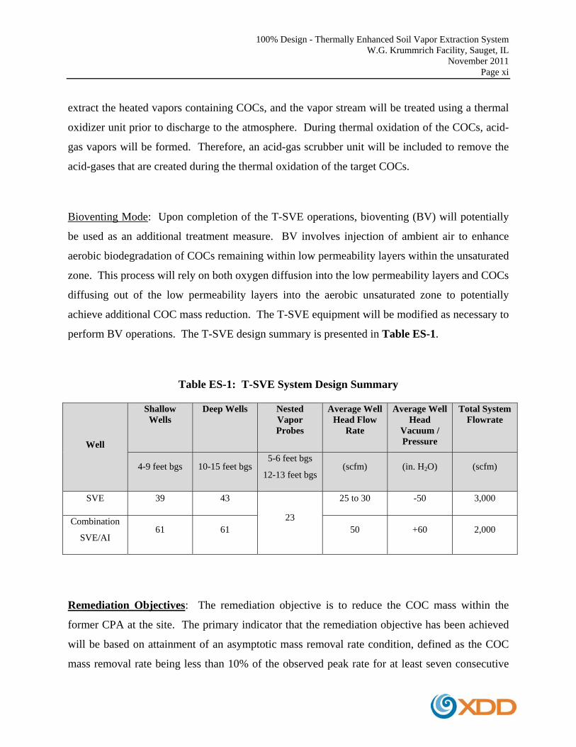
perform BV operations. The T-SVE design summary is presented in Table ES-1.
Table ES-1: T-SVE System Design Summary
Well
Shallow Wells
Deep Wells
Nested Vapor Probes
Average Well Head Flow
Rate
Average Well Head
Vacuum / Pressure
Total System Flowrate
4-9 feet bgs 10-15 feet bgs 5-6 feet bgs
12-13 feet bgs (scfm) (in. H2O) (scfm)
SVE 39 43
23
25 to 30 -50 3,000
Combination
SVE/AI 61 61 50 +60 2,000
Remediation Objectives: The remediation objective is to reduce the COC mass within the
former CPA at the site. The primary indicator that the remediation objective has been achieved
will be based on attainment of an asymptotic mass removal rate condition, defined as the COC
mass removal rate being less than 10% of the observed peak rate for at least seven consecutive

100% Design - Thermally Enhanced Soil Vapor Extraction System W.G. Krummrich Facility, Sauget, IL
November 2011 Page xii
days. Annual soil sampling data to assess COC mass reduction on the soils, and the cumulative
COC mass removal estimates from the T-SVE system will also be evaluated, and will be
considered as lines of evidence in support of the remediation objective.
T-SVE Shutdown and Potential Transition to BV Mode: When the T-SVE system achieves
an asymptotic mass removal condition, there will be little additional benefit of continuing T-SVE
operations. At that point, an evaluation of potential impacts to underlying groundwater and/or
potential human health risks associated with the residual COC concentrations remaining in the
unsaturated zone soils will be conducted. Based on the results of the risk evaluations, there are
two potential options:
If the risk evaluations indicate that there is an acceptable level of risk and/or residual
risks can be addressed by institutional controls, then a recommendation would be made to
shut down the T-SVE system.
If the risk evaluations indicate the need for further action, and BV can potentially address
the residual risk, then a transition to BV would be recommended.
A report will be prepared for the United States Environmental Protection Agency (USEPA)
making the appropriate recommendation to either shut down the T-SVE system or transition into
a BV mode of operation. Upon USEPA’s approval of either recommendation, the appropriate
action would be taken.
Operations and Monitoring: Process and performance monitoring will be conducted during
T-SVE system operations to evaluate overall vapor concentrations and track COC mass removal
rates over time. The performance data (flowrates, vacuums/pressures, temperatures, VOCs
concentrations, etc.) will be used to optimize the system operation. The system optimization
strategies will include:
100% Design - Thermally Enhanced Soil Vapor Extraction System W.G. Krummrich Facility, Sauget, IL
November 2011 Page xiii
Adjustment of steam injection ratios for the initial soil heating phase, and/or to maintain
the desired subsurface temperatures during operation.
Conducting static soil-gas rebound surveys to determine which portions of the treatment
area have achieved adequate COC mass reduction.
Maximizing VOC mass removal rates by focusing on T-SVE wells within areas of
higher vapor concentration/vapor production.
Wellfield vapor concentrations will also be periodically evaluated (using vapor probes or the
T-SVE wells under either dynamic [i.e., system on] or static [i.e., system off] conditions) to
assess the progress of the remediation. Soil sampling will also be conducted annually during the
operation for each area to assess the overall COC mass reduction.
Another key aspect to the operation strategy of the T-SVE system will be performing regular
monitoring of the site groundwater levels. The objective of this monitoring is to determine when
water levels drop sufficiently to expose the lower silty sand layer, and then take the opportunity
to reconfigure the T-SVE system to operate in that zone for as long as possible.
100% Design - Thermally Enhanced Soil Vapor Extraction System W.G. Krummrich Facility, Sauget, IL
November 2011 Page xiv
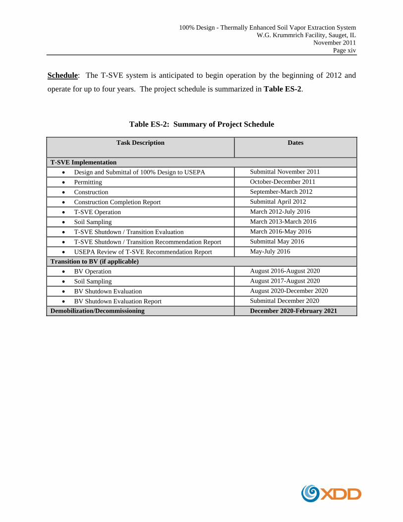
Schedule: The T-SVE system is anticipated to begin operation by the beginning of 2012 and
operate for up to four years. The project schedule is summarized in Table ES-2.
Table ES-2: Summary of Project Schedule
Task Description Dates
T-SVE Implementation
Design and Submittal of 100% Design to USEPA Submittal November 2011
Permitting October-December 2011
Construction September-March 2012
Construction Completion Report Submittal April 2012
T-SVE Operation March 2012-July 2016
Soil Sampling March 2013-March 2016
T-SVE Shutdown / Transition Evaluation March 2016-May 2016
T-SVE Shutdown / Transition Recommendation Report Submittal May 2016
USEPA Review of T-SVE Recommendation Report May-July 2016
Transition to BV (if applicable)
BV Operation August 2016-August 2020
Soil Sampling August 2017-August 2020
BV Shutdown Evaluation August 2020-December 2020
BV Shutdown Evaluation Report Submittal December 2020
Demobilization/Decommissioning December 2020-February 2021
100% Design - Thermally Enhanced Soil Vapor Extraction System W.G. Krummrich Facility, Sauget, IL
November 2011
EXECUTIVE SUMMARY FIGURE

100% Design - Thermally Enhanced Soil Vapor Extraction System W.G. Krummrich Facility, Sauget, IL
November 2011 Page 1
1.0 INTRODUCTION
This design document (100% Design) provides the drawings and specifications for the Thermally
Enhanced Soil Vapor Extraction (T-SVE) System for treatment of the former Chlorobenzene
Process Area (CPA) at the W.G. Krummrich Facility in Sauget, IL (see Figure 1).
T-SVE will be applied to the unsaturated zone soils in the CPA. A separate technology,
Enhanced Aerobic Bioremediation (EABR), will be used to treat the saturated portion of the
CPA. A separate design document has been prepared for the full-scale EABR treatment.
The following information is including in this 100% Design document:
Site background information, including a summary of geology, hydrogeology, and
distribution of the contaminants of concern (COCs) within the former CPA.
Overview of the remediation approach, including the conceptual design basis, remedial
goals, and shut-down protocols.
Design drawings for the following components:
o Subsurface well layouts, well construction details, and system manifolding.
o Process equipment design details including extraction/injection blower skids, air
controls, and water treatment equipment.
o Utility specifications (electrical, water, sewer, steam and natural gas).
o General infrastructure (equipment building, area barricading, insulating cap, etc.).
General Operations, Maintenance, and Monitoring (OM&M) protocols.
Anticipated project schedule.

100% Design - Thermally Enhanced Soil Vapor Extraction System W.G. Krummrich Facility, Sauget, IL
November 2011 Page 2
1.1 SUMMARY OF REMEDIATION APPROACH
T-SVE will be implemented within the unsaturated portion of the Shallow Hydrogeologic Unit
(SHU) (approximately 0 to 15 feet below ground surface [bgs]) using a dual-level SVE and Air
Injection (AI) well network (i.e., shallow and deep well screens). The shallow SVE/AI wells
will be designed to target the upper sandy fill/silty sand unit lying above the intermediate silty
clay layer. The deep SVE/AI wells are designed to target the lower silty sand unit below the
intermediate silty clay layer and above the water table. The intermediate silty clay layer will not
be directly targeted by the T-SVE system because it has a low permeability and is not amenable
to soil vapor extraction technology. Refer to Section 2.3 for a more detailed description of the
geology within the T-SVE target interval.
A mixture of steam and air will be injected through the AI wells to heat the subsurface soils to a
target temperature ranging between 40 and 60 degrees Celsius (°C) to increase the volatility of
the target COCs1. A light-weight insulating concrete cap (12-inches thick) will be installed over
the target area to reduce heat loss to atmosphere. The AI will also improve subsurface air flow
distribution for more uniform treatment of the soils. The SVE portion of the process will extract
the heated vapors containing COCs, and the vapor stream will be treated using a thermal oxidizer
(ThermOx) prior to discharge to the atmosphere.
Upon completion of the T-SVE operations, bioventing (BV) will potentially be used as an
additional treatment measure. BV involves injection of ambient air to enhance aerobic
biodegradation of COCs remaining within the low permeability layers of the unsaturated zone.
1 At ambient subsurface temperatures (typically 10°C), the volatility of MCB and DCB is relatively low (refer to
Appendix A for contaminant properties). By adding heat to the subsurface, the volatility of MCB and DCB would
increase, which improves the mass removal rates.
100% Design - Thermally Enhanced Soil Vapor Extraction System W.G. Krummrich Facility, Sauget, IL
November 2011 Page 3
This process will rely on both oxygen diffusion into the low permeability layers and COCs
diffusing out of the low permeability layers into the aerobic unsaturated zone to potentially
achieve additional COC mass reduction.
1.2 REMEDIATION OBJECTIVES
The remediation objective is to reduce COC mass within the former CPA at the site. Attainment
of objectives will be based upon consideration of the following lines of evidence:
1. Asymptotic Mass Removal Rate: The primary indicator that the remediation objective
has been achieved will be based on attainment of an asymptotic mass removal rate
condition by the T-SVE system. An asymptotic condition will be based upon the
observation that the COC vapor mass removal rate is less than 10% of the observed peak
rate for a period of seven consecutive days.
2. Total COC Mass Removal Estimates: Once the T-SVE system has reached an
asymptotic condition, it is anticipated that COC mass in the soils will have been reduced
substantially. Reduction of COC mass in the soils will be estimated using two methods
for comparison purposes only (a specific mass reduction target has not been established):
a. Annual soil sampling data will be evaluated to assess COC mass reduction on the
target soils as compared to baseline COC mass estimates.
b. Cumulative COC mass removal will be estimated from the vapor mass removal
rate as determined from the T-SVE operational data.
When the T-SVE system achieves an asymptotic mass removal condition, there will be little
additional benefit of continuing T-SVE operations. At that point, an evaluation of potential

100% Design - Thermally Enhanced Soil Vapor Extraction System W.G. Krummrich Facility, Sauget, IL
November 2011 Page 4
impacts to underlying groundwater and/or potential human health risks associated with the
residual COC concentrations remaining in the unsaturated zone soils will be conducted. Based
on the results of the risk evaluations, there are two potential options:
If the risk evaluations indicate that there is an acceptable level of risk and/or residual
risks can be addressed by institutional controls, then a recommendation would be made to
shut down the T-SVE system.
If the risk evaluations indicate the need for further action and BV can potentially address
the residual risk, then a transition to BV will be recommended.
A report will be prepared for the United States Environmental Protection Agency (USEPA)
making the appropriate recommendation to either shut down the T-SVE system or transition into
a BV mode of operation. Upon USEPA’s approval of either recommendation, the appropriate
action would be taken.
Process and performance monitoring data will be used to track COC vapor mass removal rates
(see Section 17.1). Well field vapor concentrations will be monitored and the T-SVE system
will be regularly optimized to ensure that the system resources are focused within the areas that
yield highest vapor removal rates (see Section 17.2). Soil data will also be collected on an
annual basis (see Section 17.3) to assess remedial performance. The T-SVE shutdown/potential
transition to BV protocol is included in Section 17.6 and Section 17.72. Note that it may be
appropriate to recommend shutdown of portions of the T-SVE system in a phased manner if sub-
areas and/or specific depth intervals meet the performance criteria.
2 The shutdown protocol is based upon the memorandum entitled “Protocol for Completing Thermally Enhanced
Soil Vapor Extraction Operations and Potential Transitioning to Bioventing Mode”, November, 2011, XDD, LLC.
100% Design - Thermally Enhanced Soil Vapor Extraction System W.G. Krummrich Facility, Sauget, IL
November 2011 Page 5
1.3 ALTERNATIVE TECHNOLOGY SELECTION
The USEPA originally issued a Final Decision (dated February 26, 2008) requiring Solutia to
implement In Situ Thermal Desorption (ISTD) within the CPA. ISTD was proposed to treat both
the unsaturated and saturated interval between surface grade and 30 feet bgs. However, based on
the results of the ISTD pilot-scale implementation and the preliminary full-scale design efforts
conducted between 2009 and 2010, ISTD treatment technology was determined to be cost-
prohibitive.
Therefore, the alternative remedy of T-SVE for the unsaturated zone and EABR for the saturated
zone was proposed by Solutia. These alternative technologies were approved by USEPA in a
letter to Solutia, dated March 11, 2011. An Explanation of Significant Difference (ESD)
memorandum, dated April 26, 2011, was also completed by USEPA to document the decision to
change the CPA remedy from ISTD to T-SVE/EABR.
100% Design - Thermally Enhanced Soil Vapor Extraction System W.G. Krummrich Facility, Sauget, IL
November 2011 Page 6
2.0 SITE BACKGROUND INFORMATION
The W.G. Krummrich Facility is a 314-acre facility located at 500 Monsanto Avenue, Sauget,
Illinois (Figure 1). The site is approximately one mile east, and in the floodplain, of the
Mississippi River. The site is located in a heavily industrialized area, and has a history of
approximately 100 years of industrial operations.
The former CPA is located in the central portion of the facility (refer to Figure 1). The CPA was
previously used for manufacturing monochlorobenzene (MCB) and dichlorobenzene (DCB)
between approximately 1926 and 2004. Numerous process tanks and overhead piping runs were
present in this area until 2009 when Solutia initiated and subsequently completed
dismantlement/demolition of the former CPA unit and associated surface features. The former
rail car loading/unloading area located directly east of and adjacent to the CPA (i.e., located
directly east of Falling Springs Road) is considered part of the CPA.
The area targeted for T-SVE treatment is an approximately 3.5 acre area. The target treatment
area is shown on Figure 2. The primary COCs that are targeted for treatment in the CPA
include3 MCB, 1,2-DCB, 1,3-DCB, and 1,4-DCB. Less significant levels of 1,2,4-
trichlorobenzene (1,2,4-TCB) and benzene are also present in the CPA. The total COC mass in
the target treatment area is estimated at 440,000 pounds (lbs). Refer to Section 2.2 for a more
detailed description of the COC distribution.
3 URS Corporation, Former Chlorobenzene Process Area Characterization Report, February 2010.
100% Design - Thermally Enhanced Soil Vapor Extraction System W.G. Krummrich Facility, Sauget, IL
November 2011 Page 7
2.1 TREATMENT AREA CHARACTERIZATION
Soil characterization was conducted by URS Corporation (URS) in 2009 and 2010 within the
treatment area. Soil cores were geologically characterized and field screened using a
photoionization detector (PID) for total volatile organic compounds (VOCs). Selected samples
were then analyzed for VOCs by USEPA Method 8260B. The results of the soil characterization
are presented in the Former Chlorobenzene Process Area Characterization Report, by URS,
submitted to USEPA in February 2010 (Characterization Report).
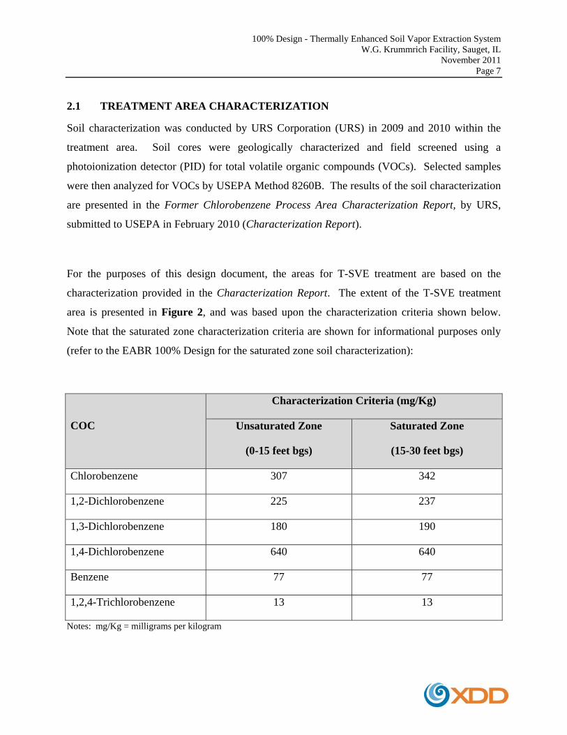
For the purposes of this design document, the areas for T-SVE treatment are based on the
characterization provided in the Characterization Report. The extent of the T-SVE treatment
area is presented in Figure 2, and was based upon the characterization criteria shown below.
Note that the saturated zone characterization criteria are shown for informational purposes only
(refer to the EABR 100% Design for the saturated zone soil characterization):
COC
Characterization Criteria (mg/Kg)
Unsaturated Zone
(0-15 feet bgs)
Saturated Zone
(15-30 feet bgs)
Chlorobenzene 307 342
1,2-Dichlorobenzene 225 237
1,3-Dichlorobenzene 180 190
1,4-Dichlorobenzene 640 640
Benzene 77 77
1,2,4-Trichlorobenzene 13 13
Notes: mg/Kg = milligrams per kilogram

100% Design - Thermally Enhanced Soil Vapor Extraction System W.G. Krummrich Facility, Sauget, IL
November 2011 Page 8
The treatment areas shown in Figure 2 were based upon the detailed soil characterization, but
areas that are inaccessible to T-SVE technology due to the presence of buildings, roads, railroad
tracks, etc., are not proposed for treatment.
According to the Characterization Report, approximately 135,000 cubic yards (CY) of soil is
impacted above the characterization criteria. This estimate includes saturated and unsaturated
zone soils between 0 and 30 feet bgs.
2.2 CONTAMINANTS OF CONCERN
As previously discussed, the primary COCs are MCB, 1,2-DCB, 1,3-DCB, 1,4-DCB,
1,2,4-TCB, and benzene. Chemical properties of these COCs are provided in Appendix A.
2.2.1 MAXIMUM SOIL CONCENTRATIONS
The maximum soil concentrations (based on the 2009-2010 soil characterization) are presented
in Table 1.
2.2.2 MASS ESTIMATES
The COC mass estimates are summarized in Table 2. Both the COC mass and the vertical
distribution of the COC mass were estimated by URS using the soil characterization data and the
Environmental Visualization System (EVC) software (EVS/MVS PRO Version 4.63). The
unsaturated zone contaminant mass for T-SVE treatment was estimated over the 0-15 feet bgs
interval. The saturated zone contaminant mass was estimated over two depth intervals (15-22
feet bgs and 22-30 feet bgs), and is shown for informational purposes only (refer to the EABR
100% Design for treatment of the saturated zone).

100% Design - Thermally Enhanced Soil Vapor Extraction System W.G. Krummrich Facility, Sauget, IL
November 2011 Page 9
2.3 GEOLOGY AND HYDROGEOLOGY
The soil in the CPA consists of a mixture of silt, sand, and gravel with occasional clay layers,
and is generally divided into three hydrogeologic units:
The SHU (Shallow Hydrogeologic Unit), between the water table (typically 15 to 17 feet
bgs) and 35 to 40 feet bgs. The unsaturated zone soils (0-15 feet bgs) above the water
table are generally considered part of the SHU.
The Middle Hydrogeologic Unit (MHU), beginning at approximately 35 to 40 feet bgs
and extending down to approximately 55 feet bgs.
The Deep Hydrogeologic Unit (DHU), between approximately 55 feet bgs and the top of
the limestone bedrock at approximately 110 feet bgs. The final 5 feet above the bedrock
is characterized as gravel with cobbles.
Three distinct soil units are observed in the upper unsaturated portion of the SHU (0-15 feet bgs):
Sandy fill/upper silty sand layer. This layer generally extends down from ground surface
to between 4 and 10 feet bgs.
Intermediate silty clay layer. This layer generally ranges in thickness between 4 and 12
feet and the top of this layer is generally encountered at depths ranging from
approximately 4 to 10 feet bgs. In at least one area, the intermediate silty clay layer is
encountered at 2 feet bgs or less (e.g., in the vicinity of soil borings CPA-30/CPA-48). In
some limited areas the intermediate silty clay layer is absent (e.g., near borings CPA-09
and CPA-55).
Lower silty sand layer. This layer is encountered below the intermediate silty clay and is
encountered at depths ranging between approximately 10 and 18 feet bgs. Note that in
some areas, the top of the lower silty sand layer is below the average water table
100% Design - Thermally Enhanced Soil Vapor Extraction System W.G. Krummrich Facility, Sauget, IL
November 2011 Page 10
elevation of 15 feet bgs (i.e., near CPA-48, CPA-63, etc.), and therefore, will not be
targeted by T-SVE (EABR will be used to treat depths below 15 feet bgs).
The T-SVE system will be designed to target the sandy fill/upper silty sand and the lower silty
sand layers. The intermediate silty clay will not be directly targeted with T-SVE technology.
The saturated portion of the SHU that is targeted for EABR treatment (i.e., 15 to 30 feet bgs)
generally consists of soils similar to the lower silty sand layer, which transitions to fine/medium
sands with depth. According to the CPA boring logs, there are indications of clay and silty clay
layers (ranging from 2 to 7 feet thick) within the SHU. The top of these clay and silty clay layers
are encountered at depths ranging from 18 to 26 feet bgs.
2.3.1 GEOLOGICAL CROSS-SECTIONS
Geological cross-sections for the treatment area are presented in the following figures:
Figure 3 – Cross-Section A-A’
Figure 4 – Cross-Section B-B’
Figure 5 – Cross-Section C-C’
2.3.2 GROUNDWATER LEVEL TRENDS
Groundwater levels within the treatment areas are directly influenced by the Mississippi River,
located approximately one mile west of the site. Since 2008, groundwater levels have been high
compared to historical data, and portions of the lower silty sand layer have been submerged.
However, based upon historical groundwater level trends, it is expected that periods of drier
100% Design - Thermally Enhanced Soil Vapor Extraction System W.G. Krummrich Facility, Sauget, IL
November 2011 Page 11
conditions will occur that will allow T-SVE to be applied within the deeper target intervals ,up to
15 feet bgs4.
As shown in Table 3, several of the existing monitoring wells in or near the CPA indicate that
the water table elevation is between 6.2 and 13.8 feet bgs as of April 2011. The locations of the
existing monitoring wells are shown on Figure 2.
Additional piezometers will be installed in the CPA as part of the EABR remedy. Refer to the
EABR 100% Design for more details on the piezometers.
4 XDD, LLC. Work Plan for Full-Scale Soil Vapor Extraction, November 2010.
100% Design - Thermally Enhanced Soil Vapor Extraction System W.G. Krummrich Facility, Sauget, IL
November 2011 Page 12
3.0 T-SVE DESIGN BASIS
A description of T-SVE technology and the design parameters used to develop the full-scale
design are provided in this section.
3.1 DESCRIPTION OF T-SVE TECHNOLOGY
The T-SVE remedy involves the use of standard SVE technology along with thermal
enhancement (refer to Section 3.3 for a discussion of thermal enhancement component of this
remedy).
Standard SVE is an in-situ remediation process designed to remove VOCs from unsaturated zone
soils by inducing air flow through the soil pores. Air flow is induced by creating a vacuum at the
well screens within the target treatment interval(s). The VOCs partition into the air stream as it
passes through the soil pores, and the air containing VOCs is subsequently extracted at the SVE
well screens.
As air is extracted from the subsurface by the SVE system, air will be drawn down from the
surface towards the well screens (i.e., infiltration of atmospheric air). Pore air will also be drawn
laterally from the outer edges of the well field, but wells in the interior portions of the well field
may receive mostly atmospheric air infiltration. The amount of air infiltration from the surface
may be limited by low permeability soil layers (e.g., such as the intermittent silty clay layer
above the lower silty sand unit in the CPA, and/or the insulating concrete cap). This can result in
competition for air between the SVE wells in the interior of the well field. The competition for
air between wells increases the required well head vacuums and decreases the overall flushing
rate of air in the subsurface.
100% Design - Thermally Enhanced Soil Vapor Extraction System W.G. Krummrich Facility, Sauget, IL
November 2011 Page 13
In this case, AI is used to supplement the SVE system to improve the subsurface air flow
distribution, and provide fresh air to volatilize the target COCs. AI is particularly advantageous
for the lower silty sand layer because the overlying intermediate silty clay unit could potentially
limit the amount of surface air infiltration, and affect SVE performance5.
The target COCs in the CPA are considered volatile; however, their volatility is somewhat low
for standard SVE/AI technology. The low volatility of these compounds can result in lower
mass removal rates, which can extend the expected remediation timeframe. Therefore, heat (i.e.,
using steam) will be added to the subsurface to increase the volatility of the target COCs. This
will make the mass removal process more efficient and potentially reduce the timeframe to
achieve the remedial goals (see Section 3.3).
3.2 SVE/AI CONCEPTUAL DESIGN BASIS
A SVE/AI (non-thermally enhanced) pilot test was conducted in the Big Mo area of the site in
2009-2010 (located southwest of CPA). For the purposes of this design, it was assumed that the
subsurface air-flow characteristics in the CPA are similar to the Big Mo area of the site since
their soil types are similar.
The SVE/AI well flowrates, wellhead vacuums/pressures, anticipated Radius of Influence (ROI)
and well spacing is based upon the 2009-2010 SVE pilot test and the Big Mo SVE system
design6,7.
5 XDD, LLC. Soil Vapor Extraction Pilot Test Report, November 2010.
6 XDD, LLC. Soil Vapor Extraction Pilot Test Report, November 2010.
7 XDD, LLC. Work Plan for Full-Scale Soil Vapor Extraction, November 2010.
100% Design - Thermally Enhanced Soil Vapor Extraction System W.G. Krummrich Facility, Sauget, IL
November 2011 Page 14
Radius of Influence: The T-SVE well network is based upon an ROI of 20 feet at 25 to
30 standard cubic feet per minute (scfm) per well.
Well Spacing: Using the above design ROI, the SVE/AI well grid was designed with an
approximate 40-foot center-to-center well spacing.
Target Depth Intervals: The T-SVE system is designed to treat the sandy fill/upper silty
sand and lower silty sand layers (refer to Section 2.3). The sandy fill/upper silty sand
layer is generally referred to as the “shallow” treatment interval. The lower silty sand
layer is referred to as the “deep” treatment interval. The intermediate silty clay layer is a
low permeability layer which will not be directly targeted during the T-SVE treatment.
Separate SVE/AI wells (shallow and deep screen intervals) will be installed in the
shallow and deep soil layers.
Air Flow Capacity of SVE/AI Systems: The SVE/AI system is designed with a total air
flow capacity to operate using up to one-half of the well screens at a given time (i.e., a
combination of shallow/deep wells, each operating at the average wellhead design
flowrates). As discussed in Section 2.3.2, seasonal fluctuations of the water table will
likely allow only intermittent operation in the lower silty sand layer. Therefore, it is
more cost effective to design the SVE/AI system with a capacity to generally focus on
one target layer at a time (i.e., shallow versus deep zones), since approximately half of
the well screens will be submerged during portions of the year.
System Flexibility/Optimization: Even though the total capacity of the system is based
on operating up to one-half of the well screens at a given time, the SVE/AI wellhead
valve control system is designed to be flexible. The SVE/AI system can be configured
using the wellhead valves to distribute system flow capacity into any combination of
100% Design - Thermally Enhanced Soil Vapor Extraction System W.G. Krummrich Facility, Sauget, IL
November 2011 Page 15
shallow and deep wells simultaneously, as water levels allow. As the system is optimized
(refer to Section 17.2), the SVE/AI system resources can be focused on the shallow
and/or deep soil hot-spots, as needed, to maximize treatment. As treatment progresses,
those areas which have achieved cleanup can eventually be taken offline, and the system
resources can then be refocused in other areas and/or depth intervals.
3.3 SOIL HEATING MODEL
The target subsurface temperature for the T-SVE treatment is between 40 to 60°C. This
temperature range is designed to increase the volatility of the target compounds to an acceptable
range (see Appendix A for COC properties).
A computer model simulation was performed to determine the minimum volume of steam
required to achieve the desired soil heating range (refer to Appendix B for the results). The
modeling was also designed to estimate the potential condensation levels from the steam
injection.
Initial Heating Phase: The soils are assumed to be at approximately 10°C initially, so a
soil temperature rise of 30 to 50°C will be required. The specific-heat capacity of soils
(i.e., heat required to raise the temperature by one degree) requires that a larger volume of
steam will initially be required to supply enough heat energy to reach the desired
temperature in a reasonable time period. Therefore, the AI/Steam manifold will be
designed to allow use of a higher volume of steam (greater than 20% by volume) for the
initial soil-heating phase. Heat losses will also be occurring from heat transfer to
atmosphere, to the intermittent silty clay layer, and to the underlying groundwater flow
below the target intervals. These potential heat sinks were included in the design
estimates. An insulating concrete surface cap is included in the design to reduce heat loss
to the atmosphere.
100% Design - Thermally Enhanced Soil Vapor Extraction System W.G. Krummrich Facility, Sauget, IL
November 2011 Page 16
Temperature Maintenance Phase: When the subsurface reaches the desired temperature,
the AI system will be reconfigured to use less steam (less than 20% by volume) to
maintain subsurface temperatures. The maintenance heat requirement is based upon
providing enough heat energy to balance the potential heat-losses (i.e., heat loss across
the insulating cap to atmosphere, etc.). This will be optimized during operation of the
system to maintain the subsurface temperatures within the target 40 to 60oC range.
100% Design - Thermally Enhanced Soil Vapor Extraction System W.G. Krummrich Facility, Sauget, IL
November 2011 Page 17
4.0 SYSTEM DESIGN OVERVIEW
The remediation approach consists of soil heating to enhance the volatility of the target COCs
(via injection of a mixture of steam and air through injection wells), and SVE to remove the
heated contaminant vapors. The extracted vapors will be treated using a thermal oxidizer
(ThermOx). The effluent vapor discharge from the ThermOx will contain hydrogen chloride
(HCl gas) from the combustion of the chlorinated COCs, which will require additional treatment
using an acid-gas wet-scrubber unit. Condensate generated by the SVE system will be treated
using an air stripper (AS) unit prior to discharge to the on-site sewer system. Light and dense
non-aqueous phase liquids (LNAPL/DNAPL) that are accumulated within the SVE system
condensate will be separated and drummed for characterization and off-site disposal.
4.1 OVERVIEW OF PROCESS FLOW
The T-SVE Process Flow Diagram (PFD) is shown in Figure 6, and the key design elements of
are outlined below:
T-SVE Wells: The system will include a dual-level SVE and AI well network (i.e.,
shallow and deep well screens). Some wells are designed to operate as combination
SVE/AI wells (i.e., can be operated in either vapor extraction or air injection modes by
configuring the gate valves provided for each well head). By configuring the
combination SVE/AI wells in either mode, subsurface air flow patterns can be modified.
The SVE and AI systems will be connected to the respective process equipment using
two separate manifold piping systems.
The SVE/AI well grid was designed with an approximate 40-foot center-to-center well
spacing (refer to Figure 7 for the well layout). A summary of the well design is
presented in the following table (also refer to Table 4).
100% Design - Thermally Enhanced Soil Vapor Extraction System W.G. Krummrich Facility, Sauget, IL
November 2011 Page 18
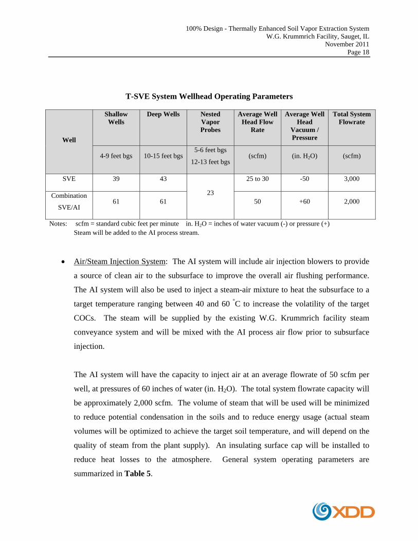
T-SVE System Wellhead Operating Parameters
Well
Shallow Wells
Deep Wells
Nested Vapor Probes
Average Well Head Flow
Rate
Average Well Head
Vacuum / Pressure
Total System Flowrate
4-9 feet bgs 10-15 feet bgs 5-6 feet bgs
12-13 feet bgs (scfm) (in. H2O) (scfm)
SVE 39 43
23
25 to 30 -50 3,000
Combination
SVE/AI 61 61 50 +60 2,000
Notes: scfm = standard cubic feet per minute in. H2O = inches of water vacuum (-) or pressure (+) Steam will be added to the AI process stream.
Air/Steam Injection System: The AI system will include air injection blowers to provide
a source of clean air to the subsurface to improve the overall air flushing performance.
The AI system will also be used to inject a steam-air mixture to heat the subsurface to a
target temperature ranging between 40 and 60 °C to increase the volatility of the target
COCs. The steam will be supplied by the existing W.G. Krummrich facility steam
conveyance system and will be mixed with the AI process air flow prior to subsurface
injection.
The AI system will have the capacity to inject air at an average flowrate of 50 scfm per
well, at pressures of 60 inches of water (in. H2O). The total system flowrate capacity will
be approximately 2,000 scfm. The volume of steam that will be used will be minimized
to reduce potential condensation in the soils and to reduce energy usage (actual steam
volumes will be optimized to achieve the target soil temperature, and will depend on the
quality of steam from the plant supply). An insulating surface cap will be installed to
reduce heat losses to the atmosphere. General system operating parameters are
summarized in Table 5.
100% Design - Thermally Enhanced Soil Vapor Extraction System W.G. Krummrich Facility, Sauget, IL
November 2011 Page 19
SVE System: The SVE portion of the process will extract the heated vapors containing
COCs, and the vapor stream will be treated using a ThermOx unit prior to discharge to
the atmosphere. The SVE system will have the capacity to extract vapors at
approximately 25 to 30 scfm per well (total capacity approximately 3,000 scfm). General
system operating parameters are summarized in Table 5.
Vapor Treatment System – Oxidizer/Scrubber Unit: Air flow from the discharge of the
SVE system will be routed to a ThermOx. The ThermOx unit will be used to destroy
COCs in the air stream prior to discharge to the atmosphere.
During thermal oxidation of the COCs, acid-gas vapors (HCl) will be formed. Therefore,
an acid-gas wet scrubber unit will be included to remove acid-gases from the process air
stream. Blow-down water from the scrubber will be discharged to the facility sewer
under permit. A water softener system may be used, if needed, to treat the incoming feed
water to the scrubber to reduce water hardness for maintenance purposes.
Condensate/NAPL Handling System: Condensation that is collected by the SVE system
will be separated from the process stream using air-moisture separators (AMS). The
condensate will be pumped from the air-moisture separators into an oil-water separator
(OWS) to remove potential NAPL from the condensate.
The condensate water will be pumped to an equalization tank (ET) for subsequent batch
treatment using an air stripper (AS) system. The treated condensate will be discharged
under permit to the plant sewer system (under permit with the American Bottoms
Regional Waste Water Treatment Facility [ABRTF]). The vapor stream from the AS will
be routed to the ThermOx unit for treatment.
100% Design - Thermally Enhanced Soil Vapor Extraction System W.G. Krummrich Facility, Sauget, IL
November 2011 Page 20
The NAPL that is separated by the OWS will be collected in the NAPL Tank (NT). The
NAPL will then be manually pumped to approved containers (with secondary
containment) for characterization and disposal.
4.2 SYSTEM CONTROLS
A programmable logic controller (PLC) will control all automated functions of the T-SVE
system. The PLC system will allow remote monitoring and review of operating status at any
time. The remote monitoring system will be used to monitor flows, vacuums/pressures, and
operating temperatures, as well as the position of safety sensors and controls (e.g., pressure
switches, level switches, motor operated valves, etc.). The PLC will also control the appropriate
system response to alarm conditions. An autodialer system will be incorporated into the design
to transmit alarm conditions to the operator.
Other monitoring devices that will be integrated with the PLC program and T-SVE operation
will include:
Vapor Probe Temperature Sensors: Temperature probes/transmitters will be provided for
real-time monitoring of subsurface temperatures at selected vapor probe locations.
Manual temperature readings will also be collected periodically from the vapor probe
networks for optimization purposes (refer to Figure 7 for the vapor probe locations).
Water Level Transducers: Because the operation of the T-SVE in the lower silty sand
unit will be contingent upon the seasonal fluctuations of the water table, water level
transducers will be provided for real-time monitoring of groundwater elevations. This
will allow forecasting of conditions and prompt re-configuration of the T-SVE to
optimize treatment in the lower silty sand unit. Manual water level readings will also be
100% Design - Thermally Enhanced Soil Vapor Extraction System W.G. Krummrich Facility, Sauget, IL
November 2011 Page 21
collected from the piezometer network in the area and will be used for the same purpose
(refer to Figure 7 for the piezometer locations).
Dissolved Oxygen (DO) Probes/Data Loggers: DO probes/data loggers will be provided
for real-time monitoring of aerobic conditions using selected piezometer locations
(Figure 7). DO readings will be accessible through the PLC and remote monitoring
telemetry system.
LEL Meter: The ThermOx unit will be equipped with a process inlet lower explosive
limit (LEL) meter which is set at a maximum of 20% of the LEL for monochlorobenzene
(0.26%; 2,600 parts per million by volume [ppmv]). If the process vapor exceeds 20%
LEL, the ThermOx unit will shut down, followed by shutdown of the SVE/AI system
Oxygen Sensors: The EABR system will be introducing pure oxygen into the saturated
zone at the same time that the T-SVE system is operating. Oxygen sensors will be
provided on the inlet to the T-SVE system to detect if elevated levels of oxygen are
entering the system. Elevated oxygen levels could affect the ThermOx unit operation and
could be a compatibility issue for the T-SVE equipment. If elevated oxygen levels (i.e.,
>23.5%) are detected, the entire T-SVE (and EABR) system would be shut down. This
alarm will also trigger the audio/visual alarm beacons (one located inside the equipment
building, and one located on the exterior of the building) and will send an autodialer
alarm message to the appropriate responders.
Building VOC Monitor and Seismic Monitor: The T-SVE equipment building will be
equipped with a PID monitor to detect potential COC vapors within the atmosphere of the
building that could result in potential leaks in the system. If vapor concentrations begin
to approach 10% of the Immediately Dangerous to Life and Health (IDLH) concentration

100% Design - Thermally Enhanced Soil Vapor Extraction System W.G. Krummrich Facility, Sauget, IL
November 2011 Page 22
for dichlorobenzene (10% of IDLH = 15 ppmv), the entire T-SVE (and EABR) system
will be shut down. This alarm will also trigger the audio/visual alarm beacons (one
located inside the equipment building, and one located on the exterior of the building)
and will send an autodialer alarm message to the system operators.
A seismic monitor will also be installed and will shut down the entire system in the event
of a significant earthquake.
Building Smoke Alarm: The T-SVE equipment building will be equipped with a
heat/smoke alarm to detect potential fire. If smoke is detected, the entire T-SVE (and
EABR) system would be shut down. This alarm will also trigger the audio/visual alarm
beacons (one located inside the equipment building, and one located on the exterior of the
building) and will send an autodialer alarm message to the appropriate responders.
4.3 SYSTEM CAPACITY AND WELL FIELD FLOW DISTRIBUTION
The SVE/AI system is designed with a total air flow capacity to operate using up to one-half of
the well screens at a given time (i.e., using a combination of shallow and/or deep wells, each
operating at the average wellhead design flowrates as shown in Table 5). This is because
seasonal fluctuations of the water table will likely allow only intermittent operation in the lower
silty sand layer. Therefore, it is more cost effective to design the SVE/AI blower systems with a
capacity to generally focus on one target layer at a time (i.e., shallow versus deep zones), since
approximately half of the well screens will be submerged during portions of the year.
Although the total capacity of the system is based on operating up to one-half of the well screens
at a given time, the SVE/AI wellhead valve control system is designed to be flexible. The
SVE/AI system can be configured using the wellhead valves to distribute system flow capacity
into any combination of shallow and deep wells simultaneously, as water levels allow. It is

100% Design - Thermally Enhanced Soil Vapor Extraction System W.G. Krummrich Facility, Sauget, IL
November 2011 Page 23
anticipated that the system will be initially started up to focus on the shallow treatment interval.
As the water table fluctuates and the lower silty sand layer is exposed, the system can be
reconfigured to target the deep interval.
4.4 GENERAL DESIGN CONSIDERATIONS
The following additional considerations were incorporated into the T-SVE system design:
Freeze protection (heaters and heat trace/insulation on process piping, etc.) for year-
round operation.
Automated systems to decrease operation and maintenance costs.
Alarm schedule built into the PLC to protect equipment and personnel.
Chemical compatibility with the COCs and temperature ranges encountered.
Location of overhead and subsurface utilities.
Compliance with National Fire Protection Association (NFPA) Class 1 Division 2
requirements for an area where ignitable concentrations of flammable gases, vapors, or
liquids are not likely to exist under normal operating conditions.
Compliance with Solutia safety standards and Occupational Safety and Hazard
Administration (OSHA) regulations.
4.5 APPLICABLE CONSTRUCTION AND SAFETY STANDARDS
The installation will be conducted in accordance with standard construction codes and guidance
documents. Where applicable, the latest revisions of the following codes shall be met.
1. ANSI – American National Standards Institute
2. ASTM – American Society for Testing and Materials
100% Design - Thermally Enhanced Soil Vapor Extraction System W.G. Krummrich Facility, Sauget, IL
November 2011 Page 24
3. CGA – Compressed Gas Association
4. FM – Factory Mutual
5. IBC – International Building Code
6. ICEA – Insulated Cable Engineers Association
7. IEEE – Institute of Electrical and Electronic Engineers
8. OSHA – Occupational Safety and Health Administration
9. NEC – National Electric Code
10. NEMA – National Electric Manufacturer’s Association
11. NFPA – National Fire Protection Association
12. UL – Underwriter Laboratories

100% Design - Thermally Enhanced Soil Vapor Extraction System W.G. Krummrich Facility, Sauget, IL
November 2011 Page 25
5.0 WELL LAYOUT AND CONSTRUCTION DETAILS
The following construction and installation details are included in this section:
T-SVE well and vapor probe locations (Figure 7).
Typical SVE/AI well construction details (Figure 8).
Typical single and nested vapor probe details (Figure 9).
Detailed well construction tables (including well depth and well screen lengths, see
Table 6 and Table 7).
5.1 T-SVE WELL AND VAPOR PROBE LAYOUTS
The dual-level SVE/AI well layout is based on a 40-foot on center spacing, designed to cover the
extent of the COC exceedances within the CPA (Figure 7). There is one area where only the
deep treatment interval is targeted (near the corner of 4th Street and Falling Springs Road);
therefore, only four deep-screened wells will be installed to treat this specific area. A summary
of the total number of wells and vapor probes is presented below:
Well Summary
Treatment Interval
T-SVE Wells Nested Vapor Probes
Screen Interval[1] SVE Combination SVE/AI
Well Count Well Count Screen Interval[1] Well Count
Shallow 3-8 feet bgs 39 61 5-6 feet bgs 23
Deep 10-15 feet bgs 43 61 12-13 feet bgs 23
Notes: [1] = Average screen intervals are shown, actual screen intervals will vary depending on actual geology.
100% Design - Thermally Enhanced Soil Vapor Extraction System W.G. Krummrich Facility, Sauget, IL
November 2011 Page 26
Combination SVE/AI Wells: Approximately 60% of the SVE wells will be configured to allow
for AI/steam injection. Note that the placement of the combination SVE/AI wells was selected
to provide additional heating capability, and to provide flexibility to optimize the injection and/or
extraction flow patterns in those areas which exhibit the highest DCB concentrations (i.e.,
specifically, within the center portion of the CPA which is bisected by 3rd Street).
Vapor Probes: In addition to the T-SVE wells, shallow and deep vapor probes will be installed
(see Figure 7). The vapor probes will be installed in the shallow and deep target zones to
monitor vacuum/pressure distribution, temperature distribution, and soil vapor concentrations.
Vapor probe placement was optimized based on the COC distribution to target the most elevated
concentrations, and to provide complete coverage of the target area. In addition, several vapor
probes are installed as “near” and “far” radius monitoring points from selected SVE/AI locations,
to monitor vacuum distribution/heat distribution as a function of radial distance from the SVE/AI
wells.
5.2 WELL CONSTRUCTION DETAILS
Typical construction details for the shallow and deep SVE/AI wells and vapor probes are
presented on Figures 8 and 9. Construction and installation details are presented in Tables 6
through 8. Well screen placement will be refined during installation based upon actual
geological conditions and COC distribution (to be verified by geological characterization and
field PID screening results, refer to Section 5.3).
5.2.1 T-SVE WELL CONSTRUCTION DETAILS
In general, shallow well screen lengths will vary between 1 and 7 feet and will be screened from
approximately 3 feet bgs to the top of the intermediate silty clay layer targeting the sandy
fill/upper silty sand layer, as shown in Table 6. Deep well screen lengths will vary between 3
100% Design - Thermally Enhanced Soil Vapor Extraction System W.G. Krummrich Facility, Sauget, IL
November 2011 Page 27
and 5 feet, and will extend from below the intermediate silty clay to approximately 15 feet bgs
targeting the lower silty sands.
As shown on Figure 8, the SVE wells will be constructed of 2-inch inside diameter (ID), 0.02-
inch slotted stainless steel (SS) well screens. The wells will be completed to surface with solid
2-inch carbon steel riser. The filter pack will consist of a #002 sand, or equivalent, which
extends a minimum of 0.5 feet above the well screen. A minimum 1-foot granular bentonite seal
will be placed above the sand pack. All boreholes will be completed to surface grade with a high
temperature compatible cement grout mixture. Well construction materials have been selected to
be compatible with the COCs and the elevated temperatures that will be present. All wells will
be installed using rotosonic drilling techniques.
5.2.2 VAPOR PROBE CONSTRUCTION DETAILS
The shallow and deep vapor probes will be installed with a 1-foot screened interval. The
screened intervals of the shallow and deep vapor probes will generally be installed at the
midpoint elevation of the adjacent shallow and deep T-SVE wells.
As shown on Figure 9, the vapor probes will be constructed of 1-inch ID, 0.02-inch slotted SS
well screens with a one-foot carbon steel sump. The vapor probes will be completed to surface
with 1-inch ID carbon steel riser. The filter pack will consist of a #002 sand, or equivalent,
which extends a minimum of 0.5 ft above the well screen. A minimum 1-foot granular bentonite
seal will be placed above the sand pack. All boreholes will be completed to surface grade with a
high temperature compatible cement grout mixture. Well construction materials have been
selected to be compatible with the COCs and the elevated temperatures that will be present. All
wells will be installed by Boart using rotosonic drilling techniques.

100% Design - Thermally Enhanced Soil Vapor Extraction System W.G. Krummrich Facility, Sauget, IL
November 2011 Page 28
5.2.3 WELL SURFACE COMPLETIONS
The wells and vapor probes will be completed to a minimum of 2 feet above surface grade with
carbon steel riser pipes. The T-SVE well riser pipes will be completed with 2-inch Female
National Pipe Thread (FNPT) adapters.
5.3 GEOLOGICAL CHARACTERIZATION
The placement of the well screen intervals for the T-SVE wells and the vapor probes is based
upon prior soil borings conducted within the CPA, and a summary of the depths is provided in
Tables 6 and 7. The well screen placements will be refined based on the profiles determined
from the soil cores obtained during the drilling program.
Continuous soil cores will be collected directly from the rotosonic core barrels from each well
location. Soil cores will be examined visually for geological characteristics and logged, and will
be compared to existing CPA boring logs by the Project Geologist. The headspace vapors from
the soils cores will be analyzed with a PID and will also be recorded.
5.4 WELL DEVELOPMENT
Piezometers will be installed as part of the EABR system monitoring well network (refer to the
EABR design document for piezometer locations), and these piezometers will be used to monitor
water level elevations to aid configuration of the T-SVE system. Saturated zone wells will be
developed using surge block and pumping until the effluent is clear or until five times the
borehole volume has been evacuated. Water, sediment, and potential NAPL generated during
well development will be handled in accordance with the waste management procedures
provided in Section 5.6.
100% Design - Thermally Enhanced Soil Vapor Extraction System W.G. Krummrich Facility, Sauget, IL
November 2011 Page 29
5.5 WELL INSTALLATION LOGISTICS
5.5.1 UTILITY CLEARANCE
The W.G. Krummrich facility utility maps were used to identify the locations of known existing
and/or abandoned utilities within the CPA. Well locations/excavation locations have been
adjusted to be clear of known subsurface utilities. Hand digging and air-knifing techniques will
be used to verify utility clearance in areas of any uncertainty.
5.5.2 PRE- AND POST-DRILLING SURVEYING
T-SVE and vapor probe locations will be marked using a flag/stake by a surveyor prior to the
start of the drilling program. Actual drilling locations may be moved by the Project Geologist to
avoid overhead obstructions (e.g., pipe racks, etc.) or in the event that subsurface obstructions
prevent installation in the desired location (i.e., drilling refusal due to concrete, cobbles, etc.).
A survey will be conducted after completion of the drilling program to determine the as-built
well coordinates.
5.6 DECONTAMINATION AND WASTE HANDLING/DISPOSAL
Soil, groundwater and decontamination fluids will be generated during the work activities. A
waste accumulation area and a decontamination area will be established within the work area.
All wastes will be containerized and properly labeled. Waste materials will be characterized and
disposed of by Solutia in accordance with all applicable regulations.
5.6.1 EQUIPMENT DECONTAMINATION AND DECONTAMINATION AREAS
Drilling equipment will be decontaminated prior to entry to the site. During drilling activities,
all equipment and vehicles will be regularly inspected to ensure contaminated materials are not
100% Design - Thermally Enhanced Soil Vapor Extraction System W.G. Krummrich Facility, Sauget, IL
November 2011 Page 30
tracked outside of the work area. Drilling equipment will also be decontaminated prior to final
demobilization from the site. Potable water for decontamination will be acquired from an on-site
hydrant (requires 24-hour notice to the plant), and will be staged in close vicinity to the
decontamination area. Tanks, water handling equipment, and all decontamination supplies will
be provided by the drilling contractor.
Primary Decontamination Area: A primary decontamination area will be constructed by the
drilling contractor within the CPA, and will include a bermed area with a polyethylene liner, or
equivalent. Decontamination of augers, drill rods, vehicles, or other large equipment shall be
performed in this area using a pressure washer. The decontamination pad will be sufficiently
sized to ensure that the largest piece of equipment can be adequately decontaminated. Also, the
area shall be designed so that vehicles can be driven into and out of the area (if required) while
maintaining containment of any accumulated fluids. The decontamination area shall also be
constructed to allow for collection of decontamination fluids and sediments, and to facilitate
transfer of these materials to drums and/or roll-offs (e.g., a sump area with pump, etc.).
Temporary Decontamination Area(s): Small pieces of drilling equipment (core barrels, etc.),
hand tools, and other miscellaneous equipment that come in contact with soils or groundwater
will be decontaminated within a temporary decontamination area. The temporary
decontamination areas may be located adjacent to the active drilling operations, and may include
6-mil polyethylene liners/berms, plastic trays, or equivalent. Decontamination of small pieces of
equipment will be performed using two water buckets (one for gross decontamination and one
for rinse), detergent (e.g., Alconox®), and brushes.
5.6.2 WASTE ACCUMULATION AREAS AND WASTE HANDLING
Soil roll-offs and drums will be staged in the designated area within the CPA. Soil roll-offs will
be equipped with rain covers with an appropriate water-shedding design to prevent pooling water

100% Design - Thermally Enhanced Soil Vapor Extraction System W.G. Krummrich Facility, Sauget, IL
November 2011 Page 31
on the surface of the cover, and will be equipped with appropriate tie downs. Roll-offs will be
secured at the end of each day’s activities. Drums will be United States Department of
Transportation (USDOT)/United Nations (UN) rated, open-top steel construction with lid gasket
seal and bolt rings.
A temporary satellite accumulation area will be established for staging of 55-gallon drums. As
needed, all 55-gallon drums will be moved to the existing waste storage warehouse (BBU
Building) located to the south of the Big Mo area.
Soils and Decontamination Derived Sediments: Soils/drill cuttings, sample cores, and
sediments from equipment decontamination will be contained in lined/covered roll-off
containers provided by Solutia. Soils containing NAPL may be segregated and remain
within drums to be disposed of separately, if required. Any drums of soil that are not
consolidated within the roll-off containers will be transferred to the waste storage
warehouse (BBU building). All soils/sediment containers will be properly labeled, and
will be characterized for disposal.
Groundwater and Decontamination Water: Impacted liquids from decontamination of
equipment and impacted groundwater from well purging/sampling will be contained in
55-gallon USDOT/UN rated drums. Drums will be properly labeled and placed in the
satellite accumulation area. When a drum is full, it will be transferred to the waste
storage warehouse (BBU building). Drums will be characterized for disposal.
Uncontaminated Bulky Waste: Uncontaminated bulky waste (i.e. general trash and other
debris) will be kept separated from impacted soil and groundwater, or other hazardous
waste streams. These wastes will be bagged, as necessary, and disposed of in a dumpster.
100% Design - Thermally Enhanced Soil Vapor Extraction System W.G. Krummrich Facility, Sauget, IL
November 2011 Page 32
NAPL Segregation: NAPL liquids will be segregated to the extent possible during waste
accumulation, and transferred to separate 55-gallon USDOT/UN rated drums. Drums
will be properly labeled and placed in the satellite accumulation area. When a drum is
full, it will be transferred to the waste storage warehouse (BBU building). Drums will be
characterized for disposal.
100% Design - Thermally Enhanced Soil Vapor Extraction System W.G. Krummrich Facility, Sauget, IL
November 2011 Page 33
6.0 MANIFOLD PIPING DESIGN
The specification of the main manifold piping system and related components required to
connect the T-SVE wells to the process equipment (i.e., SVE/AI equipment skids) are provided
in this section, and include the following:
o SVE manifold piping layouts and specifications.
o AI manifold piping layouts and specifications.
o Pipe supports and pipe saddles.
o Expansion joints, clean-outs, sumps, etc. details.
o Condensate traps.
o Pipe head loss calculations.
o Pressure testing requirements.
The layout of the SVE/AI piping is presented in Figures 10 and 11. Construction details,
including pipe supports, expansion/flex joints, cleanouts and sump details, and steam
traps/condensate traps, are presented in Figures 12 through 15. Note that process piping inside
the equipment buildings and/or connections between the SVE/AI equipment skids and other
components are not included in this section.
6.1 SVE AND AI MANIFOLD DESIGN
The SVE and AI manifold piping will provide the connection between the wellhead laterals (see
Section 7.0) and the process equipment, using two separate manifold piping systems:
The SVE manifold consists of a single pipeline to connect all of the shallow and deep
zone SVE wells.
100% Design - Thermally Enhanced Soil Vapor Extraction System W.G. Krummrich Facility, Sauget, IL
November 2011 Page 34
Similarly, the AI system consists of a single pipeline to connect to all of the shallow and
deep zone combination SVE/AI wells.
Both manifold piping systems include large diameter trunk-lines (12-inch ID and 8-inch ID), and
4-inch ID branch or lateral lines, as shown in Figures 10 and 11. The branch lines are labeled as
Legs A through Q. A summary of the piping headloss calculations are provided in Table 9.
Piping specifications are listed in Table 10. All manifold piping will be installed above ground
surface and will be supported by the pipe supports (see Figure 12, and Section 6.2 for more
details).
6.1.1 GENERAL MATERIAL COMPATIBILITY SPECIFICATIONS
In general, the SVE and AI manifold piping will be constructed of carbon steel and temperature-
rated hoses, since temperatures generated by the aerated steam will exceed 212 degrees
Fahrenheit (°F). Refer to Table 10 for piping specifications.
General materials of construction are as follows:
Steel piping will be of carbon steel (minimum Schedule 10) with either butt-weld,
threaded, or flanged fittings. Any piping requiring threaded fittings will be Schedule 40.
Control valves will be of brass body construction with polytetraflouroethylene (PTFE) or
Viton® seats/gaskets.
Seals, gaskets, and seating materials in contact with the target COCs will be of
compatible fluoroelastomer (FKM/FFKM) materials (e.g., Viton®, Kalrez®) or PTFE
materials (e.g., Teflon®), etc. Thread sealants, including pastes and tapes, will also be of
compatible PTFE formulations.
Flexible hoses will consist of inner tubes of Modified Cross-Linked Polyethylene
(XLPE), Ultra High Molecular Weight Polyethylene (UHMWPE), PTFE, or other
100% Design - Thermally Enhanced Soil Vapor Extraction System W.G. Krummrich Facility, Sauget, IL
November 2011 Page 35
chemically compatible material for use with the target COCs. The outer protective tube
cover will be Ethylene Propylene Diene Monomer (EPDM), or equivalent protective
covering.
Hose fittings will be of 316 SS construction with PTFE or Viton® seats/gaskets, or
carbon steel, as needed.
Wetted parts of sensors, transducers, transmitters, pressure gauges, flow meters, or any
other in-line instrumentations shall be of chemically compatible/temperature compatible
materials (brass, SS, PTFE, FKM/FFKM, or approved equivalents).
6.1.2 GENERAL FITTING ASSEMBLY SPECIFICATIONS
General Piping Assembly: The piping shall be constructed to the following specifications:
Flanges shall be equipped with full-faced Viton® or equivalent chemical/temperature
compatible gaskets.
Piping assemblies may be partially pre-fabricated using threaded, flanged, or butt-welded
fittings.
Piping assemblies shall be air-tight.
Pipe lengths will need to be adjusted in the field to accommodate the actual dimensions
of the field assembly.
Tee connections from the main mainline pipes to the flex-hose connections may be pre-
fabricated using flanged, threaded, or butt-weld fittings.
Straight pipe sections may be joined using butt-welded, socket-welded, or flanged
connections.
Control valves and sample ports: The control valves and sample ports will be constructed to the
following specifications:
100% Design - Thermally Enhanced Soil Vapor Extraction System W.G. Krummrich Facility, Sauget, IL
November 2011 Page 36
Control valves/sample ports shall be brass with PTFE or Viton® seats/gaskets. Valves
may be threaded, flanged, butt-welded, or socket-brazed connection.
Sample ports shall be joined to the well riser using a threaded bushing installed in the
riser pipe (bushing will be threaded or welded to the pipe).
Pipe Reducers: Pipe size reducers (for transition from large to smaller diameter pipe) will be of
eccentric design for the AI manifold. Concentric reducers will be acceptable for the SVE
manifold.
Flex Hoses: Refer to Section 7.1.2 for details of the flex hose expansion/flex joint assemblies.
6.1.3 MANIFOLD PRESSURE TESTING REQUIREMENTS
All manifold piping shall be pressure tested at the completion of the field assembly. The
pressure testing requirements are summarized in Table 11.
All utility piping and connections (discussed in Section 15.0) which are fabricated and installed
per Solutia standards (Solutia PMS B3CS2 for the steam line, B1CS2 for the natural gas line, and
D1CS1 for the water line) will be inspected and tested as specified in the standard (i.e., Solutia
Standard Procedure ESHS 507.11 for pressure and leak testing).
6.2 PIPE SUPPORTS
Pipe supports for the piping sections are detailed in Figure 12. Pipe supports will be constructed
in accordance with ASME B31.1-2011. Pipe supports will be height-adjustable to account for
required pipe slope specifications, and to account for the variable surface elevation of the final
site cover (i.e., insulating cap).
100% Design - Thermally Enhanced Soil Vapor Extraction System W.G. Krummrich Facility, Sauget, IL
November 2011 Page 37
Strut channels will be P1000 or P1001-type Unistrut® (1 5/8-inch, 12 gauge steel, green enamel
painted), or equivalent.
6.2.1 SUPPORT LOAD CAPACITY
Pipe supports will be of channel strut design (or approved equivalent), and will be fabricated to
support the cumulative weight of the T-SVE piping (SVE/AI manifolds), the EABR piping
(detailed in the EABR design document), electrical conduit piping, and other utility piping
(steam, natural gas, water, etc.).
Horizontal Span Load Capacity: A horizontal span Unistrut® can support up to 1,690 (P1000-
type) and 3,130 (P1001-type) pounds (lbs), assuming a uniformly distributed load. This
maximum load is based on allowable strut deflection, and assumes a 24-inch maximum
horizontal span (load capacity decreases with increasing horizontal span length). This maximum
load rating is reduced by a factor of 0.5 for a single concentrated load in the center of the span
(e.g., single pipe run). Assuming two concentrated loads (i.e., two pipe runs), which are placed
at one-quarter of the horizontal span length from each end (i.e., 6 inches from either end of the
maximum 24-inch long span), the load de-rating factor is 1.0.
Vertical Load Capacity (Columns): The maximum vertical load (column orientation) capacity is
3,000 (P1000-type) and 6,190 (P1001-type) lbs.
Hardware/Bracket Load Capacity: Actual pipe support capacity may be limited by hardware
load capacity (i.e., slip resistance of channel nut/bolt and type of support bracket), or for welded
assemblies, the shear strength of the welds. A ½-inch-#13 thread channel nut/bolt fitting is rated
at up to 1,500 lbs vertical load (per the Unistrut® manual).
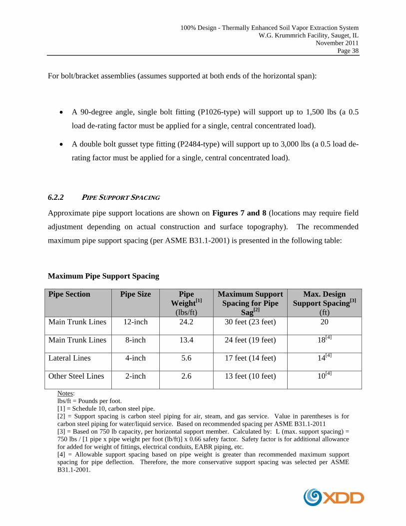
100% Design - Thermally Enhanced Soil Vapor Extraction System W.G. Krummrich Facility, Sauget, IL
November 2011 Page 38
For bolt/bracket assemblies (assumes supported at both ends of the horizontal span):
A 90-degree angle, single bolt fitting (P1026-type) will support up to 1,500 lbs (a 0.5
load de-rating factor must be applied for a single, central concentrated load).
A double bolt gusset type fitting (P2484-type) will support up to 3,000 lbs (a 0.5 load de-
rating factor must be applied for a single, central concentrated load).
6.2.2 PIPE SUPPORT SPACING
Approximate pipe support locations are shown on Figures 7 and 8 (locations may require field
adjustment depending on actual construction and surface topography). The recommended
maximum pipe support spacing (per ASME B31.1-2001) is presented in the following table:
Maximum Pipe Support Spacing
Pipe Section Pipe Size Pipe Weight[1]
(lbs/ft)
Maximum Support Spacing for Pipe
Sag[2]
Max. Design Support Spacing[3]
(ft) Main Trunk Lines 12-inch 24.2 30 feet (23 feet) 20
Main Trunk Lines 8-inch 13.4 24 feet (19 feet) 18[4]
Lateral Lines 4-inch 5.6 17 feet (14 feet) 14[4]
Other Steel Lines 2-inch 2.6 13 feet (10 feet) 10[4]
Notes: lbs/ft = Pounds per foot. [1] = Schedule 10, carbon steel pipe. [2] = Support spacing is carbon steel piping for air, steam, and gas service. Value in parentheses is for carbon steel piping for water/liquid service. Based on recommended spacing per ASME B31.1-2011 [3] = Based on 750 lb capacity, per horizontal support member. Calculated by: L (max. support spacing) = 750 lbs / [1 pipe x pipe weight per foot (lb/ft)] x 0.66 safety factor. Safety factor is for additional allowance for added for weight of fittings, electrical conduits, EABR piping, etc. [4] = Allowable support spacing based on pipe weight is greater than recommended maximum support spacing for pipe deflection. Therefore, the more conservative support spacing was selected per ASME B31.1-2001.
100% Design - Thermally Enhanced Soil Vapor Extraction System W.G. Krummrich Facility, Sauget, IL
November 2011 Page 39
For purposes of supporting the actual weight of the pipes, and for minimizing pipe sag, the pipe
support spacing is based on the following assumptions. A conservative load bearing capacity of
750 lbs, per horizontal support, is based upon the hardware support bracket maximum load
capacity of 1,500 lbs, with a 0.5 de-rating factor to account for centered point loads (worst case
scenario). An additional safety factor of 0.66 was used to account for fittings, heat
trace/insulation, EABR piping, and other ancillary piping (electrical conduits, etc.) that will be
supported on the pipe supports. Note that electrical conduits of polyvinyl chloride (PVC)
construction will require additional support to prevent excessive sag.
6.2.3 PIPE SADDLES AND ROLLER SUPPORTS
The design of the pipe saddles are shown in Figure 12. Pipe supports will be roller-type. Pipe
supports include pipe saddles to protect insulation/heat trace from crushing and allow for pipe
movement due to thermal expansion/contraction. Pre-insulated saddles may be used.
6.3 MANIFOLD PIPING DETAILS
6.3.1 EXPANSION/FLEX JOINTS
At the connection between the primary trunk lines and the lateral lines (Legs A-Q), an
expansion/flex joint will be provided to allow for thermal expansion/contraction. The expansion
joint design is presented in Figure 13.
Flex hoses will be compatible with the COCs and anticipated service temperatures:
Inner tube will be 4-inch ID and will be of XLPE, UHMWPE, PTFE, or other chemically
compatible material for use with the target COCs. Outer protective tube cover will be
EPDM, or equivalent protective covering.

100% Design - Thermally Enhanced Soil Vapor Extraction System W.G. Krummrich Facility, Sauget, IL
November 2011 Page 40
Hoses will be rated for a minimum of 200 psig (at standard operating conditions).
Hoses will be rated for a minimum of 250 °F service temperature. (Typical pressure de-
rating values are 30% for 150 to 225 °F and 50% for > 225 °F).
Hose fittings may be SS or carbon steel. Hose shank fittings will be double band
clamped/crimped with 316SS bands.
6.3.2 CLEANOUTS AND SUMPS
A clean-out access and sump assembly will be located at the terminus of each primary trunk line,
and lateral line, as show on Figure 14.
6.3.3 CONDENSATE HANDLING SYSTEM
At the terminus of each primary trunk line and lateral line on the AI piping system, a sump,
condensate trap-set, and drain will be installed (see Figure 15).
The condensate trap set will be of a mechanical float design (Spirax Sarco Model TD52, or
equivalent, refer to Table 10), and is sized for the anticipated steam condensation rate. Steam
condensate will be drained to shallow wells. Steam traps will be heat traced and insulated (per
Section 8.0, Piping Heat Trace and Insulation).
6.4 WINTERIZATION
The SVE manifold will be heat traced and insulated. The AI manifold will be insulated only.
Condensate traps and drain lines on AI manifold will be heat traced and insulated. Refer to
Section 8.0 (Piping Heat Trace and Insulation) for the heat trace and insulation design and
specifications.
100% Design - Thermally Enhanced Soil Vapor Extraction System W.G. Krummrich Facility, Sauget, IL
November 2011 Page 41
7.0 WELLHEAD CONSTRUCTION DETAILS
All T-SVE wellheads are designed with valves and sampling ports to allow for flow adjustment
and well field optimization. In addition, selected wells are equipped with valves which will
allow configuration as either SVE or AI wells (i.e., combination SVE/AI wells). The following
construction and installation details are included in this section:
o SVE wellhead design and specifications.
o Combination SVE/AI wellhead design and specifications.
o Lateral piping details for the SVE and combination SVE/AI wells.
Typical construction details for the SVE and SVE/AI wellhead assemblies are described below
and presented on Figure 16. Specifications are listed in Table 10.
7.1 SVE AND SVE/AI WELLHEAD DESIGN
The wellhead assemblies for the SVE and combination SVE/AI wells are shown in Figure 16.
Lateral piping from the SVE and SVE/AI wellheads to the main manifold piping will be
constructed of 2-inch ID carbon steel. Carbon steel will be utilized since it can withstand the
anticipated operating temperatures of the air-steam mixture (greater than 212 °F). High
temperature-rated flex hose will be used to connect the wellhead laterals to the main manifold,
which will allow for thermal expansion/contraction. The SVE lateral connection will be sloped
slightly downward towards the main piping manifold to allow condensation to drain, and be
collected by the condensate removal systems. The AI lateral connection will be sloped upward,
and the flex hose orientation is designed to prevent steam condensate accumulated within the AI
main line from flowing into the wellheads.

100% Design - Thermally Enhanced Soil Vapor Extraction System W.G. Krummrich Facility, Sauget, IL
November 2011 Page 42
7.1.1 GENERAL MATERIAL COMPATIBILITY SPECIFICATIONS
In general, the SVE and AI well heads and lateral piping will be constructed of carbon steel and
temperature rated hoses, since temperatures generated by the aerated steam will exceed 212 °F.
General materials of construction are as follows (refer to Table 10):
Steel piping will be constructed of carbon steel (minimum Schedule 10) with either butt-
weld, threaded, or flanged fittings. Any piping requiring threaded fittings will be
Schedule 40.
Control valves will be of brass body construction with PTFE or Viton® seals/gaskets.
Seals, gaskets, and seating materials in contact with the target COCs will be of
compatible FKM/FFKM materials (e.g., Viton®, Kalrez®) or PTFE materials (e.g.,
Teflon®), etc. Thread sealants, including pastes and tapes, will also be of compatible
PTFE formulations.
Flexible hoses will consist of inner tubes of XLPE, UHMWPE, PTFE, or other
chemically compatible material for use with the target COCs. The outer protective tube
cover will be EPDM, or equivalent protective covering.
Hose fittings will be of 316SS construction with PTFE or Viton® seats/gaskets, as
needed.
7.1.2 FITTING ASSEMBLY SPECIFICATIONS
Wellheads and lateral piping: The wellheads shall be constructed to the following specifications:
If flanged connections are used, the flanges shall be equipped with full-faced Viton® or
equivalent chemical/temperature compatible gaskets.
Wellhead riser/tee/sample-port and steel lateral assembly may be partially pre-fabricated
using threaded, flanged, or butt-welded fittings. Steel lateral lengths and riser height will

100% Design - Thermally Enhanced Soil Vapor Extraction System W.G. Krummrich Facility, Sauget, IL
November 2011 Page 43
need to be adjusted in the field to accommodate the actual dimensions of the field
assembly.
Tee connections from the main pipes to the flex-hose connections may be pre-fabricated
using threaded, flanged, or butt-weld fittings.
Wellhead assemblies shall be air-tight.
Wellheads may be socket brazed or butt-welded to the well risers.
Wellhead valves and sample ports: The control valves and sample ports will be constructed to
the following specifications:
Control valves/sample ports shall be brass with PTFE or Viton® seats/gaskets. Valves
may be threaded, flanged, butt-weld, or socket-brazed connection. If flanged connections
are used, the flanges will be equipped with full-faced Viton® or equivalent
chemical/temperature compatible gaskets.
The sample ports will be joined to the well riser using a threaded bushing installed in the
riser pipe (bushing will be threaded or welded to the pipe).
Flex Hoses: Flex hoses will be compatible with the COCs and anticipated service temperatures:
Inner tube will be 2-inch ID and will be of XLPE, UHMWPE, PTFE, or other chemically
compatible material for use with the target COCs.
Outer protective tube cover will be EPDM, or equivalent protective covering.
Hoses will be rated for a minimum of 200 psig (at standard operating conditions).
Hoses will be rated for a minimum of 250 °F service temperature. (Typical pressure de-
rating values are 30% for 150 to 225 °F and 50% for > 225 °F).
All hose fittings will be 316SS with Viton® gaskets. Hose shank fittings will be double
band clamped/crimped with 316SS bands.
100% Design - Thermally Enhanced Soil Vapor Extraction System W.G. Krummrich Facility, Sauget, IL
November 2011 Page 44
7.1.3 PRESSURE TESTING REQUIREMENTS
All wellheads and laterals will be pressure tested at the completion of the field assembly. The
pressure testing requirements are summarized in Table 11. The mechanical contractor will
provide the compressed air supply, temporary fittings, valves, and pressure gauges to conduct the
pressure testing.
7.2 WINTERIZATION
The wellheads and lateral assemblies will be heat traced and insulated. The well riser pipe (i.e.,
from the wellhead tee down to surface grade) will be insulated only. Refer to Section 8.0
(Piping Heat Trace and Insulation) for the heat trace and insulation design and specifications.

100% Design - Thermally Enhanced Soil Vapor Extraction System W.G. Krummrich Facility, Sauget, IL
November 2011 Page 45
8.0 PIPING HEAT TRACE AND INSULATION
The SVE manifold will be heat traced and insulated. The AI manifold will be insulated only.
Condensate traps and drain lines on the AI manifold will be heat traced and insulated. The
wellheads and lateral assemblies will be heat traced and insulated. The well riser pipe (i.e., from
the wellhead tee down to surface grade) will be insulated only. The water line and sewer line
(refer to Section 15.0) will also be heat traced and insulated (i.e., portions that are installed
above ground).
8.1.1 HEAT TRACE
The heat trace will be self-regulating (SR), thermostatically controlled and consist of industrial
series 240 volt (V) or 277 V, copper braid thermo plastic heat tape classified as NFPA Class I,
Division II. The thermostat is set to maintain a pipe temperature of 40 °F with a 5 ºF temperature
differential. Conductive aluminum heat tape will also be applied to the pipes to allow more
efficient heat transfer from the heat trace cable to the pipelines.
The heat trace electrical panel will have a NEMA 3R rating (if installed on the exterior of
equipment building). All electrical connections and fittings must comply with the Class I,
Division II specification. Light Emitting Diode (LED) trouble lights will be installed at the
termination of each strand of heat-trace to indicate a potential electrical fault.
The approximate lengths of the heat tracing for the primary SVE lines are shown on Figure 17.
Changes in heat trace length may be necessary to account for variation in pipe lengths due to
field construction variations.
100% Design - Thermally Enhanced Soil Vapor Extraction System W.G. Krummrich Facility, Sauget, IL
November 2011 Page 46
Water lines and condensate trap assemblies will be heat traced according to manufacturer’s
recommendations (i.e., number of stands and fitting/valve wrapping specifications will be
specified on the size of the respective piping system).
8.1.2 PIPE INSULATION
Insulation and protective jacketing material shall be resistant to long-term exposure to outdoor
factors such as cold, heat, and sun exposure.
Fiberglass Pipe Insulation: Pre-formed tubular fiberglass pipe insulation will comply
with ASTM C 547 and will be Class 3 (to 850 °F [454 °C]), rigid, molded pipe
insulation, and noncombustible. An integral vapor retarder jacket will be included
(consisting of kraft paper, reinforced with a glass fiber yarn, and bonded to an aluminum
foil, with self-sealing longitudinal closure laps [SSL] and butt strips, or equivalent).
Fiberglass insulation will be jacketed with aluminum (0.016” Type T-23003 H-14
sheeting, in accordance with ASTM B209), or with ultraviolet (UV) resistant PVC
jacketing (provided that the manufacturer’s recommendation with regard to pipe size,
surface temperature, and thermal expansion/contraction is followed). Insulation
thickness will be 1-inch minimum on 2-inch ID and smaller pipes, and 1.5-inch minimum
on larger pipes.
Mineral Wool Pipe Insulation (Steam Lines): Pre-formed tubular mineral wool pipe
insulation will comply with ASTM C 547, high temperature insulation (k value of 0.35 at
300 °F. Insulation thickness will be 1.5-inch minimum. Mineral wool insulation will be
jacketed with aluminum (0.016” Type T-23003 H-14 sheeting, in accordance with ASTM
B209).
100% Design - Thermally Enhanced Soil Vapor Extraction System W.G. Krummrich Facility, Sauget, IL
November 2011 Page 47
9.0 T-SVE SYSTEM DESIGN AND SPECIFICATIONS
The T-SVE system is comprised of the SVE and AI process equipment (refer to Section 4.0 for a
description of the process design). The process equipment is divided into five main components:
The SVE system to extract heated vapors from the SVE wells.
The AI system to inject air/steam into AI wells for soil heating.
The condensate handling system, designed to separate moisture (and potential
LNAPL/DNAPL) from the SVE vapor stream, and to provide treatment/discharge of the
accumulated condensate.
PLC and instrumentation specifications, including the control/interlock and input-output
schedule for the PLC (discussed separately in Section 10.0).
The vapor treatment system, designed to treat the extracted soil vapor prior to
atmospheric discharge (discussed separately in Section 11.0).
The following design details and equipment specifications are included in this section:
Process and instrumentation diagrams (P&IDs) for the SVE and AI systems, including
the condensate handling systems, oil water separator, and the air stripper.
Steam addition/air heating components.
List of process parts and equipment specifications.
PLC control logic/interlock tables.

100% Design - Thermally Enhanced Soil Vapor Extraction System W.G. Krummrich Facility, Sauget, IL
November 2011 Page 48
9.1 SVE SYSTEM EQUIPMENT
The SVE system is a high flow, low vacuum system designed to extract the heated soil vapors
from the sandy fill/upper silty sand (shallow zone) and lower silty sand layers (deep zone). The
system is designed to provide an average of between 25 and 30 scfm per well at up to 50 in. H2O
vacuum at the wellhead (not including piping headloss). The total SVE system design capacity
is 3,000 scfm.
The P&ID of the SVE system is presented on Figure 18 and specifications are provided in
Table 12. The SVE system will be designed to use three positive displacement blowers (PDB)
installed in a parallel configuration. Dividing the total system flow between three blowers has
several design advantages:
Provides redundancy - If a blower requires maintenance or fails, the SVE system can still
operate on the remaining blowers.
Reduces the size of process piping and equipment – At the lower flowrate (approximately
1,000 scfm per blower) individual process piping size is reduced. Additionally, at the
lower flowrates (i.e., ~1,000 scfm per blower), standard equipment can be used instead of
custom fabricated high volume equipment, reducing capital costs and equipment
fabrication lead times.
Provides long-term cost savings - As overall system flowrates decrease as remedial goals
are achieved in portions of the treatment area, some of the blowers can be taken off-line
as appropriate, reducing operation and monitoring (O&M) costs.
Each of the three SVE blower skids will include an in-line air particulate filter (APF) and
necessary associated valves, fittings, gauges, and sample ports (Figure 18). The primary
components of the SVE system are described below. All process piping will be constructed of
carbon steel or stainless steel.
100% Design - Thermally Enhanced Soil Vapor Extraction System W.G. Krummrich Facility, Sauget, IL
November 2011 Page 49
Vacuum Blowers – The soil vapor stream will be extracted using PDBs. The PDBs will
be designed to extract a total of approximately 3,000 scfm. Each SVE Blower will be a
ROOTSTM Rotary Positive Blower (rotary lobe type), rated for 1,000 scfm at 10 inches of
mercury (in. Hg) of total dynamic head measured at the enclosure inlet and 0 in. Hg at the
enclosure outlet. The electric motors will be totally enclosed, fan cooled (TEFC) motors.
The motor will operate at 460 volts, 3-phase power. Each blower is equipped with a
muffler/silencer to reduce noise.
Ambient Air Intake Air Filters/Silencers – A Stoddard, ambient air intake air
filter/silencer will be used for each soil vapor stream and will be rated for the flows and
vacuums of the blowers.
In-Line Air Particulate Filters – A Stoddard, high-efficiency APF will be used for each
soil vapor stream prior to the downstream blower to remove fine particle solids that could
damage the blowers.
Vacuum Relief Valves – A Kunkle, or equivalent, vacuum relief valve will be installed
and set at 16 in. Hg vacuum for each soil vapor stream to prevent excessive system
vacuum build-up.
Pressure Relief Valves – Kunkle, or equivalent, pressure relief valves will be installed on
the discharge side of each SVE blower, and will be routed to a vent line equipped with
carbon filters and flame arrestors (refer to Section 9.2.6). The vent will discharge on the
outside of the equipment building.
The final SVE process equipment specifications will be provided by the equipment fabricator,
(including blower/compressor model numbers, pump curves, motor specifications, etc.). General
specifications are provided in Table 12.
100% Design - Thermally Enhanced Soil Vapor Extraction System W.G. Krummrich Facility, Sauget, IL
November 2011 Page 50
9.2 SVE CONDENSATE HANDLING SYSTEM
Condensation that is collected by the SVE system will be separated from the process stream
using three separate AMS units in parallel. Condensate (soil moisture and potentially NAPL)
collected in the AMS will be automatically transferred to the OWS using float-switch actuated
transfer pumps. NAPL will be separated from the condensate and held in an internal storage
tank within the OWS. The OWS will be equipped with an LNAPL and DNAPL tank. When the
internal NAPL storage tanks in the OWS reaches normal capacity, the DNAPL will be manually
transferred into USDOT/UN-approved 55-gallon drums to be disposed of by Solutia. Water
from the OWS will be pumped into the ET, and then through the AS unit. After water is treated
by the AS unit, it will be discharged to the facility sewer under permit with the ABRTF.
The P&ID for the condensate handling system is presented on Figure 18 and specifications are
provided in Table 12. A summary of the design of each primary component of the condensate
handling system is described in the following sections.
9.2.1 AIR MOISTURE SEPARATORS
Each SVE process stream will pass through a dedicated AMS. Each AMS is designed with a
240-gallon capacity and is capable of a maximum 10 gallon per minute (gpm) discharge rate to
the OWS. All three AMS units are equipped with low-level, high-level, and high-high level
sensor switches. The low-level and high-level switches operate their corresponding transfer
pumps. The high-high level float is designed to prevent overfilling of the AMS units; and if any
of these switches are actuated, they trigger a controlled shutdown of the entire system.

100% Design - Thermally Enhanced Soil Vapor Extraction System W.G. Krummrich Facility, Sauget, IL
November 2011 Page 51
9.2.2 OIL WATER SEPARATOR
The condensate from the AMS units will be pumped through the OWS. The OWS unit is
designed to separate potential LNAPL/DNAPL from the condensate collected by the AMS units.
The OWS will have a maximum treatment flow capacity of 30 gpm (intermittent/batch flow; 12
gpm continuous flow). The OWS will have a 73-gallon, effluent pump out compartment and
integral NAPL storage compartment.
The coalesced NAPL, if any, will be collected in internal LNAPL/DNAPL Tanks. The NAPL
Tanks are equipped with high-level sensors that will send an autodialer signal to the system
operator when either of the internal NAPL Tanks has reached a pre-determined level (and needs
to be drained). A high-high level sensor will detect if the NAPL Tanks have reached maximum
capacity and will trigger a full shut-down of the SVE/AI systems, including the ThermOx unit.
The NAPL will be drained manually as needed, and will be pumped to an external NAPL storage
drum with secondary containment (refer to Section 9.2.5).
The OWS will have a passive venting system which will be routed to a vent line equipped with
carbon filters and flame arrestors (refer to Section 9.2.6). The vent will discharge on the outside
of the equipment building.
9.2.3 EQUALIZATION TANK
A 300-gallon, SS equalization tank will be used to store water discharged from the OWS, and
will allow for batch treatment of the accumulated condensate when necessary. The ET will be
equipped with low-level, high-level, and high-high level sensor switches which will be
interlocked with the AS unit and will control pump on/off status. The high-high level float is
designed to prevent overfilling of the tank, and when actuated, this switch signals a controlled
shutdown of the entire system. The ET will have a passive venting system which will be routed
to a vent line equipped with carbon filters and flame arrestors (refer to Section 9.2.6). The vent
will discharge on the outside of the equipment building.
100% Design - Thermally Enhanced Soil Vapor Extraction System W.G. Krummrich Facility, Sauget, IL
November 2011 Page 52
9.2.4 AIR STRIPPER UNIT
The water accumulated in the ET will be transferred to the AS system for batch treatment. The
treated condensate will be discharged to the sewer in accordance with applicable discharge
permits. VOC-impacted air from the AS will be combined with the SVE vapor stream and
treated via the ThermOx unit (refer to Section 11.0).
The unit will be a NEEP Systems, Inc. (NEEP) Model 2321-P, high density polyethylene
(HDPE) Shallow Tray Air Stripper, equipped with two SS stripping trays, and a 3 Hp 460V
TEFC electric motor. This model is designed to treat up to 50 gpm with a minimum of 98%
removal of chlorobenzenes from the condensate. A flow totalizer unit is installed on the
discharge side of transfer pump to monitor the total treated water discharge from the AS system.
9.2.5 NAPL STORAGE DRUM
The NAPL storage drum will be a standard USDOT/UN rated 55-gallon steel drum with two
bung openings. The NAPL storage drum will be placed on a secondary containment unit. This
assembly is show on Figure 18.
The outlet from the OWS internal NAPL tanks are connected to a chemical transfer pump, which
will discharge through a chemical-compatible hose system (Transfer Hose) into the NAPL
storage drum. The Transfer Hose system will be equipped with ball-valves on each end. The
Transfer Hose system will only be connected to the NAPL drum during the actual transfer.
During filling of the NAPL storage drum, the drum will be vented using the second bung
opening with a flexible piping system connected to a carbon filter vent unit (refer to Section
9.2.6). The drum will be supplied with a dedicated electrical grounding clamp, and grounding
rod installed by a qualified electrician.
100% Design - Thermally Enhanced Soil Vapor Extraction System W.G. Krummrich Facility, Sauget, IL
November 2011 Page 53
9.2.6 CARBON FILTER VENTILATION SYSTEM
The OWS and ET units will be passively vented through a 30-pound granular activated carbon
(GAC) drum via flexible hose connections. The discharge of the GAC drum is equipped with a
flame arrestor and a PVC pipe discharge stack.
The vent (bung) of the NAPL storage drum will also be temporarily connected to this GAC drum
via flexible hose connections (but only during the process of manually filling of the drum) for
passive ventilation purposes (see Section 9.2.5).
A separate GAC drum unit (with flame arrestor and discharge stack) will be provided for the
discharge side of the three SVE system pressure relief valves. This vent system will be
completely independent of the vent system used for the OWS, ET and NAPL drums.
9.3 AI SYSTEM EQUIPMENT
The AI system is a high flow, low pressure system designed to increase the efficiency of the SVE
system by providing atmospheric air to the shallow and deep soil intervals. In addition, the AI
system will be used to inject a steam-air mixture to heat the subsurface soils to a target
temperature ranging between 40 and 60 °C. The steam will be supplied by the existing W.G.
Krummrich facility steam conveyance system and will be mixed with the AI process air flow
prior to subsurface injection. The AI system will have the capacity to inject air at an average of
50 scfm per well at pressures of 60 in. H2O. The total AI system design capacity is 2,000 scfm.
The P&ID of the AI system is presented in Figure 19 and specifications are shown in Table 13.
The AI system will use two compressors installed in a parallel configuration. Two compressors
will provide redundancy, reduce the size of associated process piping on each skid, and
potentially provide long-term O&M cost savings. Each of the AI process streams will be
constructed with the necessary components for independent operation, including an ambient air
intake and all associated valves, fittings, and gauges.
100% Design - Thermally Enhanced Soil Vapor Extraction System W.G. Krummrich Facility, Sauget, IL
November 2011 Page 54
The major components of the air/steam injection process equipment are described below. All
process piping will be constructed of carbon steel or SS construction.
Air Compressors – Two PDBs with a total capacity of up to 2,000 scfm will be provided.
The pressure capacity will be based upon an estimated wellhead pressure requirement of
up to 60 in. H2O. The electric motor will be TEFC and will operate at 460 volts, 3-phase
power. Each blower is equipped with a muffler/silencer to reduce noise.
In-Line Air Particulate Filter (APF) – A Solberg, high-efficiency APF will be used to
remove fine particle solids to prevent damage to the compressor.
Pressure Relief Valves (air component) – Kunkle, or equivalent, pressure relief valves
will be installed on the air injection lines to prevent excessive pressure build-up in the
system, and to regulate injection pressure to avoid creating preferential pathways for air
movement.
Pressure Relief Valves (steam component) – Spirax Sarco, or equivalent, pressure relief
valves will be installed on the steam injection lines to prevent excessive pressure build-up
in the system.
Steam Inlet – Steam will be blended with the AI process air at variable air-to-steam
volume ratios. The steam will be obtained from the existing W.G. Krummrich steam
conveyance piping system. A motorized valve will be provided to control the addition of
steam, which will be controlled by a temperature transmitter located downstream of the
air/steam mixing point. A solenoid shutoff valve (normally closed) will also be included
on the steam inlet to shut off the supply in the event of a system shutdown or power
failure.

100% Design - Thermally Enhanced Soil Vapor Extraction System W.G. Krummrich Facility, Sauget, IL
November 2011 Page 55
Steam Condensate System: Some steam will condense within the AI manifold prior to
reaching the injection wells. The AI manifold system will be equipped with appropriate
condensate traps, drains, and controls to remove condensate from the system to prevent
water accumulation and potential pipe blockage. This condensate will not require
treatment as it will be clean coming from the W.G. Krummrich plant steam conveyance
system.
AI process equipment specifications will be provided by the equipment fabricators (including
blower/compressor model numbers, pump curves, motor specifications, etc.). General
specifications are provided in Table 13.
9.4 SYSTEM INSTRUMENTATION
System instrumentation includes various process indicators, such as flow meters,
pressure/vacuum gauges, temperature meters, etc.
9.4.1 MANUAL READ INSTRUMENTATION
Miscellaneous air flow meters, vacuum/pressure, and temperature gauges are located along the
system manifold, wellheads and process piping to monitor these operating parameters. In
addition, liquid totalizers and sample ports for vapor/liquids are provided in key locations.
Instrumentation specifications (e.g., sample ports, direct read vacuum/pressure and flow gauges,
temperature gauges, etc.) are presented in Tables 12 and 13.
Flow Totalizer (FT) – Direct-read water totalizer units to measure total water/condensate
discharge from the process (FT 701 is located at the discharge of the AS system).
Flow Meters (FM) – Direct read instruments for measuring vapor flow rates at the
specific process location.
100% Design - Thermally Enhanced Soil Vapor Extraction System W.G. Krummrich Facility, Sauget, IL
November 2011 Page 56
Hour Meters (HM) – Indicates run time of the associated equipment, and can be used for
tracking maintenance schedules or evaluating operational/shutdown time periods.
Pressure Indicators (PI) – Direct read instruments for measuring pressure at the specific
process location.
Sample Ports (SP) – Used to sample liquid or vapor at the specific process location.
Some sample ports (such as on the individual wellheads) serve multiple purposes and can
be used to measure vacuum or pressures, or can be used to measure wellhead flow rates
with portable instrumentation. Selected sample ports on the discharge side of the SVE
system and the condensate handling system are spring-loaded/self-closing types to
prevent accidental releases due to sample ports left open.
Temperature Indicators (TI) – Direct read instruments for measuring temperature at the
specific process location.
Vacuum Indicators (VI) – Direct read instruments for measuring vacuum at the specific
process location.
9.4.2 ANALOG/DIGITAL INSTRUMENTATION
The system will be equipped with electronic sensors to monitor the various systems, and to
ensure that the system is operating within design specifications. A summary of the SVE and AI
input-output schedule is included in Table 14.
The following controls provide measurement of various operational parameters, and transmit
these readings (electronically) to the control panel/telemetry system for remote readings.
Flow Indicators, Analog (FIA) – These controls are designed to provide an air flow rate
measurement and readout (on a digital or analog meter) in the various process piping
systems. These controls also transmit the air flow readings to the control panel/telemetry
system for remote readings.
100% Design - Thermally Enhanced Soil Vapor Extraction System W.G. Krummrich Facility, Sauget, IL
November 2011 Page 57
Flow Sensors (FS) – These sensors are located on the discharge of the SVE and AI
Systems. They are designed to indicate an alarm condition of minimal flow/no flow (due
to shutdown of the blowers, break/blockage of the process piping, or improper valve
settings). These are flow vane type switches, actuated by the momentum of the air flow
within the process piping, and deactivated when the air flow ceases within the respective
piping system. These are set with a 30-second delay before arming, to allow the SVE/AI
systems to come up to speed when initially started.
Temperature Indicators, Analog (TIA) – These controls are designed to provide a
temperature measurement and readout (on a digital or analog meter) in the various
process piping systems. These controls also transmit the temperature readings to the
control panel/telemetry system for remote readings.
Vacuum Indicators, Analog (VIA) – These controls are designed to provide vacuum
measurement and readout (on a digital or analog meter) in the various process piping
systems. These controls also transmit the vacuum readings to the control panel/telemetry
system for remote readings.
Pressure Transmitters/Pressure Switches (PT/PS) – These are located on the discharge
side of the SVE and AI blower systems. These controls are designed to transmit a
pressure reading to the control panel/telemetry system, and also to detect over-pressure
conditions (due to pipe blockage or improper valve settings in the process piping), which
would trigger a system shutdown.
9.4.3 AUTOMATION CONTROLS
Automation controls trigger equipment responses, such as turning liquid transfer pumps on or
off, or indicate alarm conditions, such as high liquid levels in tanks. Alarm conditions triggered
by these controls are presented in Table 14. The status of these sensors can be observed from
the control panel/telemetry system for remote tracking purposes.
100% Design - Thermally Enhanced Soil Vapor Extraction System W.G. Krummrich Facility, Sauget, IL
November 2011 Page 58
Level Sensors (LS) - Located on AMSs, OWS/NT, ET, and AS systems. These sensors
are designed to trigger the transfer pump cycles (on and off), and to sense liquid levels to
prevent overfilling of the various tanks.
Motorized Valves/Solenoid Valves (MV, MBFV, SV) – Motorized valves and solenoid
valves will be used to control flow rates and/or provide shut-down of critical portions of
the process flow in the event of alarm conditions.
9.5 MATERIAL COMPATIBILITY AND ASSEMBLY SPECIFICATIONS
9.5.1 MATERIALS OF CONSTRUCTION
General materials of construction are as follows:
Steel piping will be constructed of carbon steel (minimum Schedule 10) with either butt-
weld, threaded, or flanged fittings. Any piping requiring threaded fittings will be
Schedule 40. Steam piping will be Schedule 80 carbon steel.
Control valves will be constructed of brass body construction with PTFE or Viton®
seats/gaskets.
Seals, gaskets, and seating materials in contact with the target COCs will be constructed
of compatible FKM/FFKM materials (e.g., Viton®, Kalrez®) or PTFE materials (e.g.,
Teflon®), etc. Thread sealants, including pastes and tapes, will also be constructed of
compatible PTFE formulations.
Flexible hoses, if used, will consist of inner tubes of XLPE, UHMWPE, PTFE, or other
chemically compatible material for use with the target COCs. The outer protective tube
cover will be EPDM, or SS (for high pressure), or equivalent protective covering.
Hose fittings will be constructed of 316SS construction with PTFE or Viton®
seats/gaskets, as needed.
100% Design - Thermally Enhanced Soil Vapor Extraction System W.G. Krummrich Facility, Sauget, IL
November 2011 Page 59
Wetted parts of sensors, transducers, transmitters, pressure gauges, flow meters, or any
other in-line instrumentations will be constructed of chemically compatible/temperature
compatible materials (brass, SS, PTFE, FKM/FFKM, or approved equivalents).
9.5.2 ASSEMBLY SPECIFICATIONS
General Process Piping Assembly: The process piping shall be constructed to the following
specifications:
Process pipes may be joined using butt-welded, socket-welded, or flanged connections.
Outlets of process piping from each major equipment skid will be threaded or flanged to
allow field connection to the field piping at the equipment building. Flanged connections
will be equipped with Viton® or equivalent chemical/temperature compatible gaskets.
Piping assemblies will be air-tight. Equipment will be leak-tested prior to delivery.
Control valves and sample ports: The control valves and sample ports will be constructed to the
following specifications:
Control valves/sample ports will be brass with PTFE or Viton® seats/gaskets. Valves
may be threaded or socket-brazed connection.
The sample ports will be joined to the well riser using a threaded bushing installed in the
riser pipe (threaded or welded).
Flex Hoses: Flex hoses will be compatible with the COCs and anticipated service temperatures:
Inner tube will be 2-inch ID and will be of XLPE, UHMWPE, PTFE, or other chemically
compatible material for use with the target COCs.
Outer protective tube cover will be EPDM, or equivalent protective covering.
Hoses will be rated for a minimum of 200 psig (at standard operating conditions).
100% Design - Thermally Enhanced Soil Vapor Extraction System W.G. Krummrich Facility, Sauget, IL
November 2011 Page 60
Hoses will be rated for a minimum of 250 °F service temperature. (Typical pressure de-
rating values are 30% for 150 to 225 °F and 50% for > 225 °F).
All hose fittings will be 316SS with Viton® gaskets. Hose shank fittings will be double
band clamped/crimped with 316SS bands.
Pipe Reducers: Pipe size reducers (for transition from large to smaller diameter pipe) will be of
eccentric design for the AI manifold. Concentric reducers will be acceptable for the SVE
manifold.
100% Design - Thermally Enhanced Soil Vapor Extraction System W.G. Krummrich Facility, Sauget, IL
November 2011 Page 61
10.0 PROGRAMMABLE LOGIC CONTROLLER AND INTERLOCKS
Automated functions of the T-SVE system (specifically the SVE and AI systems shown in
Figures 18 and 19) will be controlled using a PLC. The system control input/output schedule is
provided in Table 15. The PLC will control appropriate system responses to alarm conditions,
and will use an autodialer to send alarm messages to the system operators.
The vapor treatment system (see Section 11.0) will include separate, dedicated PLC systems
specifically designed to control the ThermOx and acid-gas scrubber units (supplied by the
equipment manufacturer to control the respective units). These dedicated PLCs will be
interlocked with the T-SVE system PLC, and will trigger appropriate alarm responses. The
EABR system will also have a dedicated PLC to control automated functions, and will be
interlocked with the T-SVE system (refer to the EABR design document for more details of the
EABR PLC).
10.1 SYSTEM CONTROL SPECIFICATIONS
The main control panel for the T-SVE system will be constructed to NEMA 4X standards. All
lights, selector switches, push buttons, and all other panel face-mounted devices will be clearly
and properly labeled with white letters engraved on black metal labels. Any system reset
switches that need to be energized to function will be located on the exterior of the main control
panel. Additionally, all panel internal devices, wires, and terminals will be properly labeled.
10.1.1 PROGRAMMABLE LOGIC CONTROLLER
System operation and responses to instrumentation and alarm conditions will be controlled via a
High Safety PLC interface (Allen-Bradley Compact GuardLogix or equivalent), which provides
redundant processors in the event of a primary system hang-up.
100% Design - Thermally Enhanced Soil Vapor Extraction System W.G. Krummrich Facility, Sauget, IL
November 2011 Page 62
The interlock wiring between the T-SVE, EABR, and ThermOx/Scrubber PLCs, and other
external sensors, is shown on Figure 20. The seismic switch (SS 701) and two oxygen sensors
(OS/OT 001 and 401) will be installed in the T-SVE Equipment Buildings and will be wired to
both the EABR and T-SVE PLCs to cause a complete system shut-down if tripped. Additional
field wiring will include eleven (11) temperature probes and four (4) water level transducers
which will be accessible via the system telemetry (refer to Figure 21).
10.1.2 GRAPHICAL USER INTERFACE AND REMOTE TELEMETRY SYSTEM
A Graphical User Interface (GUI) will be used to monitor flows, pressures, and operating
temperatures, as well as the position of safety sensors and controls (e.g., pressure switches, level
sensors, solenoid valves, etc.). The GUI is a C-More EA7 Touch Panel unit, or equivalent.
A telemetry system will be incorporated to allow remote monitoring of the operational status and
process data (i.e., air flowrates, vacuums, pressures, and temperatures, oxygen levels, etc.). A
cellular connection will be installed with the PLC for telemetry access. If the telephone
connection is lost, the entire system will be shut off and a local light or siren alarm will activate.
10.1.3 AUTODIALER
An autodialer system with battery backup is used to transmit specific system status and alarm
conditions to the system operator (per Table 15). A cellular autodialer/telemetry line will be
installed with the PLC for communications. If the telephone connection is lost, the entire system
will be shut off and a local light or siren alarm must activate.

100% Design - Thermally Enhanced Soil Vapor Extraction System W.G. Krummrich Facility, Sauget, IL
November 2011 Page 63
10.1.4 EMERGENCY STOP BUTTONS
Emergency Stop buttons will be provided at the system PLC control panels (1 button), within the
building (1 location), and outside the building (1 location). Shutting off the SVE/AI will
automatically send a control signal to shut off the ThermOx unit.
10.1.5 THERMAL OXIDIZER LEL METER
The ThermOx unit will be equipped with an inlet LEL meter which is set at a maximum of 20%
of the LEL for monochlorobenzene (0.26%; 2,600 ppmv). If the process vapor exceeds 20%
LEL, the ThermOx will shut down, followed by shutdown of the SVE/AI system.
10.1.6 BUILDING VOC MONITOR AND SEISMIC MONITOR
A photoionization detector (PID 701) VOC monitor will be provided to monitor the atmosphere
within the equipment building. In general, if a PID measurement greater than 1 ppmv is
detected, this could indicate a minor vapor or liquid leak within the trailer. If vapor
concentrations begin to approach 10% of the Immediately Dangerous to Life and Health (IDLH)
for dichlorobenzene (10% of IDLH = 15 ppmv), the system will shut down and the system
operators will be notified.
If the VOC monitor detects VOC concentrations in the building, a beacon light/alarm siren will
sound to notify personnel of this condition so that proper procedures can be followed.
A seismic monitor (SS701) will also be supplied and will shut down the entire system in the
event of a significant earthquake.
10.1.7 AUDIO/VISUAL ALARM BEACONS
Two audio/visual alarm beacons will be installed in the equipment building. One will be inside
the building and one will be outside. If a general shutdown/alarm occurs, the strobe light beacon

100% Design - Thermally Enhanced Soil Vapor Extraction System W.G. Krummrich Facility, Sauget, IL
November 2011 Page 64
will turn on. If a serious alarm condition occurs (smoke alarm, or VOCs detected in the building,
etc.) the strobe and audio siren will turn on, and the system will shut down.
10.1.8 OXYGEN SENSORS
The EABR system (refer to the EABR design document) will be introducing pure oxygen into
the saturated zone at the same time that the T-SVE system is operating. Oxygen sensors will be
provided on the inlet to the T-SVE system to detect if elevated levels of oxygen are entering the
system. Elevated oxygen levels could affect the ThermOx unit operation and could be a
compatibility issue for the T-SVE equipment. If elevated oxygen levels are detected, the entire
T-SVE (and EABR) system will shut down.
The oxygen sensors will be installed on a sampling loop within the process piping, which will
allow vapors to cool and allow for maintenance/calibration operations (refer to Figure 18 and
Table 12).
10.1.9 VAPOR PROBE TEMPERATURE SENSORS
Eleven temperature probes/transmitters will be provided for real-time monitoring of subsurface
temperatures at selected vapor probe locations. The temperature probes will be AquiStar® T16
Smart Sensors, or equivalent. Manual temperature readings will also be collected periodically
from the vapor probe networks for optimization purposes. The location of the temperature
probes are shown on Figure 21.
10.1.10 WATER LEVEL TRANSDUCERS
Because the operation of the T-SVE in the lower silty sand unit will be contingent upon the
seasonal fluctuations of the water table, water level transducers will be provided for real-time
monitoring of groundwater elevations. Four water level transducers will be provided for real-
100% Design - Thermally Enhanced Soil Vapor Extraction System W.G. Krummrich Facility, Sauget, IL
November 2011 Page 65
time monitoring of groundwater elevations and will require an external input for the system PLC
(Table 14). Inputs to the PLC will be provided for these transducers. This will allow
forecasting of conditions and prompt re-configuration of the T-SVE to optimize treatment in the
lower silty sand unit. Manual water level readings will also be collected from the piezometer
network in the area and will be used for the same purpose. The location of the water level
transducers are shown on Figure 21.
10.1.11 DISSOLVED OXYGEN PROBES/DATA LOGGERS
DO probes/data loggers will be provided for real-time monitoring of aerobic conditions at 10
selected piezometer locations. DO readings will be accessible through the PLC and remote
monitoring telemetry system.
10.2 PROCESS CONTROL STANDARDS
Solutia requires that all controllers, sensors, and electro-mechanical actuated valves which are
used to control a process be evaluated and classified in a Level of Protection Analysis (LOPA).
The purpose of the LOPA is to ensure that safety-critical instruments and controls are designed,
tested, and/or certified to perform with a required level of reliability (i.e., “Integrity Level” or
“IL”). The LOPA evaluation is conducted to assess the safety of the system due to
environmental, and/or property damage that could occur as a result of a potential failure of each
control/interlock. Based on this assessment, the required IL classification of each
control/interlock is determined. A LOPA analysis has already been conducted by Solutia for this
system and all of the system controls and interlocks have been classified.
Based on the LOPA assessment, the following requirements are part of this 100% Design:
Sensors: Sensors include flow, level, temperature, etc. switches and transmitters that are used as
part of a Basic Process Control System (BPCS) interlock.
100% Design - Thermally Enhanced Soil Vapor Extraction System W.G. Krummrich Facility, Sauget, IL
November 2011 Page 66
1. Sensor failure must not initiate the hazard, which means the sensor is separate and
independent of control functions.
2. The sensor should be certified to IEC61508 with an integrity level claim limit that
matches the classification. A BPCS requires an “IL-1”. Sensor manufacturers may have
certifications other than IEC that may be satisfactory and will be evaluated on a case by
case basis.
Final Elements: Final elements include solenoid valves, process valves, dampers, etc. that are
used as part of a BPCS interlock.
1. Final element failure must not initiate the hazard, which means the final element is
separate and independent of control functions.
2. The final element should be certified to IEC61508 with an integrity level claim limit that
matches the classification. A BPCS requires an “IL-1”. Final element manufacturers
may have certifications other than IEC that may be satisfactory and will be evaluated on a
case by case basis.
Controllers: Controllers are programmable controllers that run the system, including the
processor and input/output modules.
1. The controller must have redundancy or on-line diagnostics to achieve a PFD (Probability
of Failure on Demand Final) = 0.01 and have the program logic and set points password
protected.
General Requirements: Sensors, final elements and controllers must fail to a safe state on loss
of signal, power or instrument air.
100% Design - Thermally Enhanced Soil Vapor Extraction System W.G. Krummrich Facility, Sauget, IL
November 2011 Page 67
11.0 VAPOR TREATMENT SYSTEM SPECIFICATIONS
The vapor treatment system is designed to treat the extracted soil vapor prior to atmospheric
discharge. Air flow from the discharge of the soil vapor extraction (SVE) system will be routed
through a ThermOx and acid-gas scrubber prior to discharge to the atmosphere. Refer to
Figures 22 and 23 for a general process schematic diagram of the ThermOx and acid-gas
scrubber unit. Refer to Table 16 for a summary of the ThermOx operating specifications.
The following details and specifications are included in this section:
P&ID for the ThermOx and acid-gas scrubber unit.
List of oxidizer/scrubber unit(s) design specifications.
Estimated natural gas consumption rates.
11.1 THERMOX SYSTEM
The ThermOx vapor treatment system is designed for an initial process flow rate of 4,000 scfm,
and will oxidize volatile organic compounds in SVE discharge prior to release. Treated vapors
will be discharged under an Illinois Environmental Protection Agency (IEPA) air discharge
permit.
The ThermOx design specifications are summarized below:
One Regenerative Thermal Oxidizer (RTO).
The ThermOx unit will have a total flow rate capacity of 4,000 scfm.
The ThermOx unit will be capable of achieving a 98% minimum destruction and removal
efficiency (DRE).
100% Design - Thermally Enhanced Soil Vapor Extraction System W.G. Krummrich Facility, Sauget, IL
November 2011 Page 68
The ThermOx will be equipped with an inlet LEL meter which is set at a maximum of
20% of the LEL for monochlorobenzene (0.26%; 2,600 ppmv). If the process vapor
exceeds 20% LEL for chlorobenzene, the ThermOx system will shut down, followed by
shutdown of the entire SVE/AI system. The LEL meter will be located on the ThermOx
inlet, after the air dilution valve (Figure 22).
The ThermOx unit will be designed to withstand an internal deflagration within the
combustion chamber without rupturing through to the exterior of the equipment materials
and passing the resultant pressure wave through the discharge stack.
The ThermOx unit will induce draft, which allows for any leaks in the system to be
inward, eliminating any fugitive emissions and making routine operation and
maintenance safer.
Natural gas will be piped from an on-site supply line to fuel the ThermOx unit (refer to
Section 15.1 for utility connection information).
The ThermOx unit will be constructed with materials compatible with acid-gas vapors.
Oxygen sensors will be installed in the SVE and ThermOx unit inlets to detect potential
elevated oxygen levels resulting from the EABR treatment of the saturated zone. If
excess oxygen is present, this will signal the entire SVE/AI system to shut down.
The ThermOx unit will be designed, built and installed to be in compliance with all
applicable NFPA codes.
The ThermOx unit will operate at a temperature of at least 1,500 °F whenever the affected
system is generating vapors.
11.2 ACID GAS SCRUBBER
Hydrogen chloride (HCl) is a corrosive gas formed during thermal oxidation of chlorinated
organic compounds. Therefore, a wet-scrubber unit will be used to strip the acid-gases that are
100% Design - Thermally Enhanced Soil Vapor Extraction System W.G. Krummrich Facility, Sauget, IL
November 2011 Page 69
created during the thermal oxidation of the target COCs. Hydrogen chloride scrubbers
incorporate a variety of gas-liquid contacting techniques, including packed beds, spray chambers
and water jets. The exhaust of the ThermOx unit will be routed to the wet-scrubber and a water
spray (up to 20 gallons per minute) will be used to strip the acid-gas from the air stream.
Hydrochloric acid is formed when HCl gas is dissolved in spray water. This water will be
discharged to the site sewer under the appropriate permit.
Refer to Figure 23 for a general process schematic diagram of the acid-gas scrubber unit. The
acid-gas scrubber unit will be fitted to the air discharge process stream from the ThermOx unit.
Blow-down water from the wet-scrubber will be discharged to the facility sewer under permit.
The general acid-gas scrubber design specifications are summarized below:
The acid-gas scrubber will be a vertical scrubber with a design capacity of 4,000 scfm.
The scrubber unit will achieve a 99% minimum hydrochloric acid (HCl) removal
efficiency, based on the concentrations estimated below:
Estimated Pre-Treatment HCl Values
Compound Estimated Maximum
Concentration (ppmv)
Estimated HCl Load (pounds per hour)
HCl 2,300 40
The scrubber unit will be constructed of materials able to withstand acid vapor and be
compatible with the temperatures expected to be encountered for a minimum five-year
design life.
The scrubber unit will be winterized with a scrubber heater, heat trace, and insulation.
100% Design - Thermally Enhanced Soil Vapor Extraction System W.G. Krummrich Facility, Sauget, IL
November 2011 Page 70
12.0 EQUIPMENT BUILDING
12.1 EQUIPMENT BUILDING AND EQUIPMENT LAYOUT
The process equipment and components associated with the T-SVE system will be housed in two
prefabricated steel shipping containers: one will house the SVE equipment and the other the AI
system. The containers and major equipment will be installed west of Falling Springs Road
between 2nd and 3rd Streets, as shown on Figure 25. Other general specifications are provided in
Table 17. Refer to Section 14.0 for electrical details of the containers.
The equipment enclosure will require, at a minimum, the following specifications (Table 17):
Building dimensions: 16 feet wide x 45 feet long x 10-11 feet high
Conformance to all state (Illinois) and local (Sauget) building and safety codes, as
applicable.
A photoionization detector (PID 701 on Figure 18 and Table 12) VOC monitor
will be mounted on the exterior of the housing to monitor the atmosphere within
the equipment container/building and will result in a system shutdown and alarm
condition should atmospheric concentrations exceed 15 parts per million by
volume (ppmv) as chlorobenzene.
A seismic monitor (SS701) will be installed in one of the enclosures.
Smoke alarms with audio and visual indicators on the interior and exterior of the
housing. The smoke alarms/alarm beacons will be provided as a loose part for the
skid option.
A minimum of two (2) 36” man doors. Man doors will be lockable, capable of
fully opening with holdbacks, and 36 inches wide per NFPA 101, Section
7.3.4.1(2) (Table 17). The egress must be unobstructed, clearly visible and
marked and lighted as needed.
A minimum of one 72-inch double wide access door with entry sweep and lock.

100% Design - Thermally Enhanced Soil Vapor Extraction System W.G. Krummrich Facility, Sauget, IL
November 2011 Page 71
Fluorescent overhead lighting in accordance with National Electric Code (NEC)
illumination requirements.
Emergency lights and glow-in-the-dark egress route outlined on the floor.
Two audio/visual alarm beacons will be installed in the equipment building. One
will be inside the building and one will be outside. If a general shutdown/alarm
occurs, the strobe light beacon will turn on. If a serious alarm condition occurs
(smoke alarm, or VOCs detected in the building, etc.) the strobe and audio siren
will turn on, and the system will be shut down.
Interior framed and insulated (R-13), rain/sound insulated hoods for vent fans and
fresh air intakes.
Connections for electrical, natural gas, sewer, water, steam, and phone line
systems.
Interior temperature switch/heat detector/alarm (TSH) is also provided in the
event that temperatures exceed design parameters within the building. If the set
point is reached inside the building, the entire system will shut down.
Interior and exterior emergency (E-stop) switches.
12.1.1 ELECTRICAL SPECIFICATIONS
Electrical service at 480V will be supplied to the trailer. All circuit breakers, disconnects, and
transformers, will be constructed Class I, Division II Standards and will be indicated as such.
Electrical schematic drawings detailing proper labeling of all wires, terminals, and all internal
and external panel devices will be provided by the fabricator. The following are additional
specifications.
Electrical wiring will meet Class I, Division II standards/NFPA 85.
Fabrication of electrical panels and connections for 480V power service. A transformer
to accommodate the system’s 120V electrical needs, and additional 20 amperes of 120V
to be wired to the oxygen supply tank.
100% Design - Thermally Enhanced Soil Vapor Extraction System W.G. Krummrich Facility, Sauget, IL
November 2011 Page 72
Exterior grounding and lightning rod protection to be specified by the contractor and
installed in the field by others.
Fluorescent overhead lighting in accordance with National Electric Code (NEC)
illumination requirements.
Two GFI outlets on each main wall.
12.1.2 VENTILATION SPECIFICATIONS
Thermostatically controlled ventilation with a minimum of 10 building exchanges per
hour capacity. During summer months, the interior temperature of the enclosure will be
thermostatically controlled with ventilation fan(s) capable of ventilating at a minimum
capacity of 10 building exchanges per hour, or a similarly adequate means. The
ventilation system must be capable of keeping the interior temperature within the
operating limits of all equipment, not to exceed 140 °F.
Thermostatically controlled electrical heater(s) for thermal protection of the building.
The Site location frequently experiences temperatures below freezing (32 °F). Since the
enclosure will contain equipment that is temperature-sensitive, a thermostatically
controlled heating system will be installed keeping the interior temperature within the
operating limits of all equipment as specified, but not below 60 °F. The electrical
connection associated with the heater will be pre-wired so it can be easily connected to
the electrical breaker panel in the field.
Vents will be located to discharge above the roofline of the building with sufficient stack
height to allow dispersion. Vents will be equipped with rain hats and screens (to prevent
animal entry/nesting). All equipment will be leak tested to ensure that oxygen/nitrogen is
not leaking into the enclosed building.
12.1.3 ENCLOSURE NOISE REQUIREMENTS
The equipment enclosure must include noise dampening materials as required to prevent
nuisance noise and provide less than 85 dBA at 10 feet distance where possible. Additionally, all

100% Design - Thermally Enhanced Soil Vapor Extraction System W.G. Krummrich Facility, Sauget, IL
November 2011 Page 73
external points of ventilation on the enclosure will be fitted with sound dampening louvers to
minimize noise transmission at the Site.
12.1.4 EMERGENCY EYEWASH STATION
One emergency eyewash station will be provided in each equipment container. The eyewash
stations will be mounted on one of the two man doors in each container.
12.1.5 FIRE EXTINGUISHERS AND FIRST AID KITS
Multipurpose fire extinguishers (for Class A, B, and C fires) will be maintained within the
equipment containers and carried on personnel vehicles at all times. These extinguishers will be
capable of extinguishing ordinary combustibles, flammable liquids and gases, and electrical
equipment fires. Three 20-pound ABC fire extinguishers will be maintained (one inside each
equipment container and one mounted on the power pole closest to the Main Power Panel). Fire
extinguishers will be inspected on a periodic basis (per manufacturer’s requirements).
A first aid kit will also be maintained within the equipment containers and will be inspected on a
periodic basis to ensure the contents are current.

100% Design - Thermally Enhanced Soil Vapor Extraction System W.G. Krummrich Facility, Sauget, IL
November 2011 Page 74
13.0 INSULATING CONCRETE SURFACE COVER
A light-weight concrete surface cover will be installed at the site to provide thermal insulation
and reduce heat losses to atmosphere during the soil heating operations.
13.1 SITE GRADING
The Site will be graded to an approximate 2.0% to 2.5% surface grade to prepare the surface for
the installation of the insulating concrete cap. Additional fill material will be used, as necessary,
to achieve the required grade elevations in low areas. A 12-inch gravel/crushed stone berm will
be built around the perimeter of the treatment areas to be used as a form for the insulating
concrete cap installation.
13.2 CONCRETE SURFACE COVER
A concrete surface cover will be installed over the target area, as shown in Figure 25. The
surface cover will be designed to provide a minimum R-value of 18. The surface cover design
calls for a lightweight, cellular concrete mix (25 to 30 pounds per cubic foot [pcf]) material at a
minimum of 12 inches thick.
100% Design - Thermally Enhanced Soil Vapor Extraction System W.G. Krummrich Facility, Sauget, IL
November 2011 Page 75
14.0 ELECTRICAL DESIGN
The electrical service for the entire system will originate from the substation to the east of
Falling Springs Road (refer to Figure 26). Electrical cables will be connected to Substation #1,
and will be installed using the existing overhead pipe rack and cable trays, and utility poles, as
necessary. A single 13.8 kilovolt (kV) feeder cable will feed a transformer to provide 480 V
service for all the equipment. Three power poles will be installed (as shown in Figure 26) to
provide a drop to the main system power panel (PP-1).
14.1 ELECTRICAL SYSTEM DETAILS
The majority of equipment at the site will operate at 480 V. All equipment inside the containers
will be Class I Division II specification (with the exception of some of the AI equipment which
may be segregated and electrically non-classified). The electrical loads for the SVE/AI system
components are summarized on Table 18.
14.1.1 MAIN POWER AND SUB-PANEL LAYOUT
The locations of the main power and transformers to feed all the equipment is shown on
Figure 27. The main power panel (PP-1) will provide power to various breakers, as shown in
the electrical line diagram on Figure 28.
14.1.2 SENSORS AND INTERLOCKS WIRING DIAGRAM
The PLC computers for each of the main systems will be interlocked with one another to provide
automated control/alarm/shutdown functions. Interlock wiring is shown on Figure 20 and will
include:
100% Design - Thermally Enhanced Soil Vapor Extraction System W.G. Krummrich Facility, Sauget, IL
November 2011 Page 76
T-SVE PLC connection with the ThermOx PLC.
T-SVE PLC connection with the Scrubber PLC.
T-SVE PLC connection with the EABR PLC.
In addition, sensors will be installed in the vapor probes and piezometers within the well field
(refer to Figure 21) and will be interlocked with the T-SVE PLC, including:
Eleven temperature probes.
Ten DO probes.
Four water level pressure transducers.
14.1.3 MISCELLANEOUS ELECTRICAL CONNECTIONS
Miscellaneous electrical connections are shown in Figure 27, and include:
Lightning rod protection for the ThermOx/Scrubber discharge stack.
Grounding rods for the panels/subpanels and NAPL drum.
The NAPL drum will require a dedicated grounding rod and clamping system to ground the
drum during transfer operations.
100% Design - Thermally Enhanced Soil Vapor Extraction System W.G. Krummrich Facility, Sauget, IL
November 2011 Page 77
15.0 UTILITY SPECIFICATIONS
The following utility services will be installed in the CPA:
Natural Gas Line: Natural gas is required to operate the ThermOx units. A natural gas
connection and pipeline will be tied into the existing plant natural gas supply system.
Sewer Line: A sewer pipeline and connection to the facility sewer will be installed for
discharge of the treated SVE condensate.
Water Line: A water pipeline and connection to the facility water supply will be installed
for operation of the acid-gas scrubber.
Steam Line: Steam is required to supply the thermal component of the T-SVE system. A
steam connection and pipeline will be tied into the existing plant 200-pound steam supply
system.
15.1 UTILITY CONNECTIONS
Location of the facility utilities (fire protection systems, natural gas, sewer, water, and steam)
and the connections to the T-SVE system are shown in Figures 29 through 37. The
approximate location of the process equipment building/container is also shown in these figures.
15.1.1 FIRE PROTECTION WATER SYSTEM
As shown on Figure 29, there is a fire hydrant located approximately 60 feet from the northeast
corner of the equipment area.
15.1.2 NATURAL GAS LINE DETAILS
The ThermOx unit system will be connected to the plant’s natural gas supply (connection will be
to the MRT gas line and a 2-inch connection will be provided). The location of the connection to
100% Design - Thermally Enhanced Soil Vapor Extraction System W.G. Krummrich Facility, Sauget, IL
November 2011 Page 78
the plant’s natural gas supply is shown on Figure 30. The natural gas pipeline controls/valves
and other equipment is shown on the figure. The gas line will be constructed of 2-inch Schedule
40 carbon steel pipe and will be welded construction. Piping materials, specifications, and
construction will be in accordance with Solutia’s PMS B1CS2 standard, and will be
pressure/leak tested per Solutia Standard Procedure ESHS 507.11. Materials and construction
specifications are provided on Figure 31.
The pipeline will be supported on the existing overhead pipe supports running along Falling
Springs Road and will be connected at an available tie point near the southern fence line of the
property. Portions of the pipeline that will be installed ground level will be protected by 8-foot
concrete jersey barriers spaced 4 feet apart.
15.1.3 SEWER LINE DETAILS
The sewer pipeline will connect to the plant’s existing sewer 4-F, as shown on Figures 32 and
33. The pipeline will carry a maximum flow of up to 35 gpm. The above ground portions of the
sewer line will be heat traced and insulated. A sewer pipeline and connection to the facility
sewer will be installed for discharge of the treated condensate and for the scrubber discharge.
The sewer pipeline will be installed above grade and will be constructed of 2-inch and 3-inch ID,
Schedule 80, CPVC, for compatibility with HCl generated by the scrubber system. The sewer
line will be labeled with “HYDROCHLORIC ACID” with an adhesive backed weather/UV
resistant label.
The sewer line will discharge to the 4-F manhole. The manhole is constructed of concrete and
lined with acid brick and vinyl ester (epoxy) coating.
100% Design - Thermally Enhanced Soil Vapor Extraction System W.G. Krummrich Facility, Sauget, IL
November 2011 Page 79
15.1.4 WATER LINE DETAILS
The acid-gas scrubber unit requires a water supply for scrubber operations. Water will be
supplied from a plant water supply connection shown on Figure 34. The water line will be
constructed of 2-inch ID carbon steel, and will be heat traced and insulated. The plant water line
(6 inch ID) is installed below ground (estimated to be less than 3 feet below grade). A tee
connection with a key operated valve will be tapped into the existing line and extended upward
above grade. The water line piping details are shown on Figure 35.
Piping materials, specifications, and construction will be in accordance with Solutia’s PMS
D1CS1 standard, and will be pressure/leak tested per Solutia Standard Procedure ESHS 507.11.
15.1.5 STEAM LINE DETAILS
The thermal component of the T-SVE system will require a mixture of air and steam (“aerated
steam”).
A steam connection and pipeline will be tied into the existing plant 200-pound steam supply
system. The existing plant connection and the steam line piping details are shown on
Figures 36 and 37. The steam line will be constructed of 2-inch ID, carbon steel piping and will
be constructed in accordance with W.G. Krummrich plant requirements.
Piping materials, specifications, and construction will be in accordance with Solutia’s PMS
B3CS2 standard, and will be pressure/leak tested per Solutia Standard Procedure ESHS 507.11.
15.2 PRESSURE TESTING REQUIREMENTS
All utility piping and connections (discussed in Section 15.1) which are fabricated and installed
per Solutia standards (Solutia PMS B3CS2 for the steam line, B1CS2 for the natural gas line, and
100% Design - Thermally Enhanced Soil Vapor Extraction System W.G. Krummrich Facility, Sauget, IL
November 2011 Page 80
D1CS1 for the water line) will be inspected and tested as specified in the standard (i.e., Solutia
Standard Procedure ESHS 507.11 for pressure and leak testing).
15.3 BARRICADES
Concrete barriers will be placed in key areas to protect critical utilities (such as natural gas or
steam lines), if required.
100% Design - Thermally Enhanced Soil Vapor Extraction System W.G. Krummrich Facility, Sauget, IL
November 2011 Page 81
16.0 IMPLEMENTATION TASKS
16.1 PERMITTING
Permits will be required for several operations during this project. The permit requirements will
be renewed/updated as necessary for each phase of work and are summarized below.
16.1.1 AIR QUALITY CONSTRUCTION PERMIT AND AIR QUALITY OPERATING PERMIT
Solutia will obtain the necessary permits for construction and operation of the off-gas treatment
system. An IEPA construction permit will be required. The off-gas treatment systems will be
designed, built, and operated to ensure compliance with all applicable regulations.
16.1.2 WATER DISCHARGE PERMIT
Treated condensate will be discharged to the plant’s sewer system via a temporary connection for
treatment at the Village of Sauget P-Chem Plant and the ABRTF. A modification to the plant’s
existing permit will be required.
16.1.3 UNDERGROUND INJECTION CONTROL NOTIFICATION
Injection of steam into the subsurface is subject to the IEPA’s Underground Injection Control
(UIC) Program. A Class V notification will be submitted for this activity.
16.2 DESIGN AND PROJECT OPERATIONS PLANS
The design and project operations plans described in the following sections will be developed for
work at the site. The plans will be updated as required.
100% Design - Thermally Enhanced Soil Vapor Extraction System W.G. Krummrich Facility, Sauget, IL
November 2011 Page 82
16.2.1 HEALTH AND SAFETY PLAN
A site-specific Health and Safety Plan (HASP) will be developed. The HASP will cover work
activities, and will integrate with the facility-specific safety requirements.
16.2.2 OPERATIONS, MAINTENANCE, AND MONITORING MANUAL
An Operations, Maintenance, and Monitoring (OM&M) Manual will be developed including
area-specific details. This manual will include staffing requirements, standard procedures for
work activities, and other instructions for the operations staff. This manual will focus on how to
track performance, general maintenance procedures, and how to determine when operations are
complete.
16.2.3 SAMPLING AND ANALYSIS AND QUALITY ASSURANCE PROJECT PLANS
A combined Sampling and Analysis Plan (SAP) and Quality Assurance Project Plan (QAPP) will
be developed for the work activities described in this document.
16.2.4 SPILL PREVENTION, CONTROL, AND COUNTERMEASURE PLAN
A Spill Prevention, Control, and Countermeasure Plan (SPCC Plan) will be prepared for the
activities associated with the project. The SPCC Plan will address the following elements:
Operating procedures that will be employed to prevent oil or hazardous materials spills.
Control measures that will be installed to prevent a spill.
Countermeasures to contain, clean up, and mitigate the effects of a spill.

100% Design - Thermally Enhanced Soil Vapor Extraction System W.G. Krummrich Facility, Sauget, IL
November 2011 Page 83
16.3 MOBILIZATION
Staff, materials, and equipment will be mobilized to the site to implement the remediation
system, per the schedule as discussed in Section 18.0. Basic mobilization and site preparation
activities include the following tasks:
Fabrication of necessary components (blowers, ThermOx unit, AS units, etc.).
Perform survey and utility marking.
Mobilize temporary facilities (office trailer, storage container, restroom facilities, etc.).
Establish exclusion zones.
Construct equipment pads (gravel and/or concrete) as required.
Staffing during the mobilization phase is expected to include a Construction Manager and up to
two field technicians. Local subcontractors may also be contracted to perform site construction
tasks, as required.
16.4 SITE SECURITY
Portions of the treatment area will be barricaded with concrete barriers, and the equipment
buildings will have locking doors. The W.G. Krummrich Plant’s Security will be provided with
keys to the locks for all gates.
16.5 WELL INSTALLATION
Installation of all SVE/AI wells and vapor probes will be conducted using rotosonic drilling
technology. Refer to Sections 5.1 and 5.2 for a description of the SVE/AI wells and vapor probe
construction details.

100% Design - Thermally Enhanced Soil Vapor Extraction System W.G. Krummrich Facility, Sauget, IL
November 2011 Page 84
Drill cuttings will be transferred to appropriate containers, analyzed, and disposed of off-site at
an appropriate disposal facility.
16.6 INSULATING CAP INSTALLATION
The insulating concrete cap will be installed by a qualified contractor. The insulating cap will be
installed in phases after various sections of wells/vapor probes are installed.
The insulating cap design calls for a lightweight, cellular concrete mix (25-30 pounds pcf)
material approximately 12 inches thick.
16.7 MANIFOLD INSTALLATION
A mechanical piping subcontractor will be contracted to install the manifold systems (including
all connections between the ThermOx, Scrubber, and other SVE/AI equipment as necessary),
and wellhead controls.
This task will also include installation of the freeze protection equipment, consisting of heat-
trace/insulation and heated enclosures for appropriate equipment.
16.8 EQUIPMENT INSTALLATION
The SVE/AI equipment installation will include set-up and field connections of equipment that
has been pre-fabricated by the equipment manufacturer. A mechanical and electrical contractor
will be subcontracted for the field piping and electrical connections, respectively.
100% Design - Thermally Enhanced Soil Vapor Extraction System W.G. Krummrich Facility, Sauget, IL
November 2011 Page 85
16.9 SYSTEM START-UP/EQUIPMENT SHAKEDOWN
Equipment shakedown will be performed to ensure all automation and safety controls are fully
functional. The equipment shakedown will be performed with the SVE/AI wellfield shut off
from the system so that there is no potential discharge during the pre-start testing. The system
shake-down activities will include:
A pre-startup safety review meeting to confirm that the system construction and final
installation satisfies the Solutia Process Hazard Analysis (PHA) review.
Pressure test all major piping.
Leak-check vapor, liquid, and steam transfer lines.
Test liquid and vapor treatment systems with clean water and air.
Check all motors for proper rotation.
Verify and calibrate all instrument signals.
Verify all analog and discrete signals to/from the PLC.
Set all valves to the proper pre-start positions.
Collect background VOCs, vacuum/pressure, temperature, and water level data.
16.10 SYSTEM OPERATION
The system operation phase will include general operation, monitoring, and maintenance which
is discussed in Section 17.0.
16.11 SYSTEM DEMOBILIZATION
After completion of T-SVE operations and/or BV operations (refer to Sections 17.6 and 17.7),
the T-SVE/BV system will be either demobilized/decommissioned.

100% Design - Thermally Enhanced Soil Vapor Extraction System W.G. Krummrich Facility, Sauget, IL
November 2011 Page 86
Well Abandonment: As treatment in each area is completed, the SVE/AI wells and vapor probes
will be abandoned per 35 Illinois Administrative Code 920 and other applicable IEPA
regulations and guidelines.
Equipment Removal/Salvage: Equipment will be removed and/or salvaged at the end of active
operations.
Site Restoration: Prior to demobilizing, rough grading will be performed as needed to maintain
adequate drainage, berms or swales constructed for the project will be removed, and the site will
be returned to a condition substantially similar to its condition prior to the start of construction.
100% Design - Thermally Enhanced Soil Vapor Extraction System W.G. Krummrich Facility, Sauget, IL
November 2011 Page 87
17.0 OPERATION AND MONITORING
This section provides a description of the operation strategies, vapor monitoring programs, and
soil sampling programs to meet the remediation objectives. This section also includes a brief
description of the anticipated day-to-day operation tasks, including process monitoring, general
maintenance, and logging/reporting requirements. These activities will be fully outlined in the
OM&M manual for the project (refer to Section 16.2.2).
The schedule and operational sequence for treatment of the CPA is provided in Section 18.0.
17.1 GENERAL SYSTEM MONITORING
The general system operations include routine process monitoring, performance monitoring, and
compliance monitoring. The goal of monitoring is to record T-SVE system data to assess the
progress towards the remediation objectives. Additional details regarding the system monitoring
activities will be included in the OM&M manual (refer to Section 16.2.2).
17.1.1 PROCESS MONITORING
Process monitoring includes measurement of flow rates, vacuums/pressures, vapor
concentrations, and temperature data at multiple points within the SVE and AI process streams.
This also includes monitoring water/condensate (e.g., ET levels and totalizer readings), NAPL
recovery rates, and the operating parameters of the ThermOx, scrubber, and AS units.
The process monitoring data will be used to evaluate the mechanical performance of the system
to ensure that equipment is operating within the desired performance range (i.e., target flow
rates) and within manufacturer’s specifications. In addition, this data will aid in identifying
mechanical issues and/or for system troubleshooting purposes.
100% Design - Thermally Enhanced Soil Vapor Extraction System W.G. Krummrich Facility, Sauget, IL
November 2011 Page 88
17.1.2 PERFORMANCE MONITORING
Performance monitoring data generally includes:
1. Measurement of vapor concentrations in the T-SVE process (via field PID measurement
and/or vapor samples for laboratory analysis).
2. Measurement of vapor concentrations, vacuums/pressures, flowrates, temperatures at
wellheads and vapor probes (to assess subsurface air flow patterns and changes in vapor
concentrations as the system is operated over time).
The performance monitoring data is used in conjunction with the process monitoring data to
estimate the vapor mass removal rates, total mass removed by the T-SVE system, and provide
data regarding vapor concentrations remaining in the subsurface.
17.1.3 COMPLIANCE MONITORING
Compliance monitoring data has a specific purpose to satisfy the air and water discharge permit
requirements. Compliance monitoring generally includes:
1. Sampling the T-SVE system vapor concentrations to confirm treatment efficiency of the
ThermOx, and ensure air permit compliance.
2. Sampling the AS influent/effluent water concentrations, to confirm treatment efficiency
of the AS, and ensure water discharge permit compliance.
17.1.4 GROUNDWATER LEVEL MONITORING
A key aspect to the operation strategy will be regular monitoring of the site groundwater levels.
As of May 2011, water table elevations have been at a historical high, which has submerged the
lower silty sand layer. Part of the operation strategy is to determine when water levels drop
100% Design - Thermally Enhanced Soil Vapor Extraction System W.G. Krummrich Facility, Sauget, IL
November 2011 Page 89
sufficiently to expose the lower silty sand layer, and then take the opportunity to reconfigure the
T-SVE to operate in that zone for as long as possible.
Groundwater levels will be monitored in the treatment areas using nearby monitoring wells
during routine site checks (or using remote data-loggers, if desired). Several piezometers will be
installed in the vicinity of the treatment area for the EABR system operation which will be used
for this purpose. In addition, four pressure transducers equipped with remote telemetry will be
installed four monitoring wells to allow for real time monitoring of the water levels by the
engineering and project management.
17.2 WELL FIELD OPTIMIZATION
The following well flow optimization strategies will be employed during the operation phase of
the T-SVE system:
Adjustment of steam injection ratios for the initial soil heating phase, and/or to maintain
the desired subsurface temperatures during operation.
Conduct static soil-gas rebound surveys to determine which portions of the treatment
area have achieved adequate COC mass reduction (which would be quantified with soil
sampling).
Maximizing VOC mass removal rates as much as possible by focusing on T-SVE wells
within areas of higher vapor concentration/vapor production.
Details and the anticipated intervals of optimization events will be included in the OM&M
manual (refer to Section 16.2.2).
100% Design - Thermally Enhanced Soil Vapor Extraction System W.G. Krummrich Facility, Sauget, IL
November 2011 Page 90
17.3 SOIL SAMPLING
Soil cores will be collected and field-screened for total organic vapors at discrete intervals using
a PID and jar vapor-headspace methods. Screening results will be considered when selecting the
soil interval to be submitted for laboratory analysis of VOCs by USEPA Method 8260.
The soil data will be used to assess overall COC mass reduction on the soils over the course of
the remediation process. A brief description of the soil sampling program is included in this
section. A more detailed soil sampling program, with soil sample counts, depths, locations, and
selection criteria, will be discussed in the SAP (refer to Section 16.2.3). Soil sampling will be
conducted annually.
17.3.1 BASELINE SOIL SAMPLING
The 2009-2010 soil characterization sampling data (refer to the Characterization Report) will be
used as the baseline soil concentrations. The initial COC mass in each treatment area was based
on this data and was discussed in Section 2.2.2.
17.3.2 INTERIM SOIL SAMPLING
Interim sampling will be performed to demonstrate the progress of soil treatment. Interim soil
samples will be collected annually following start-up of the SVE/AI system, as applicable (refer
to the schedule in Section 18.0).
17.3.3 FINAL SOIL SAMPLING
Based on process and performance monitoring data, when the SVE/AI system has reached an
asymptotic mass removal condition (refer to Section 1.4), a final soil sampling event will be
conducted to determine the overall level of COC mass reduction on the soils.

100% Design - Thermally Enhanced Soil Vapor Extraction System W.G. Krummrich Facility, Sauget, IL
November 2011 Page 91
17.4 DATA EVALUATION
Process and performance monitoring data will be entered into a spreadsheet to track trends in the
data. Review of this data (with graphical presentation of trends as applicable) will allow
evaluation of:
1. Contaminant mass removal rates and totals (as vapor, water, and NAPL).
2. Soil heating performance.
3. Changes in operational parameters of system process equipment (such as increasing or
decreasing flowrates, vacuums/pressures, temperatures, etc.) that may indicate changes in
the remedial process, or impending maintenance issues.
4. Wellfield performance (including observations of vacuums/pressures and changes in
VOCs levels at the wellheads and vapor probes). This data will be used to assess if
wellfield optimization is necessary for optimal air flow or mass removal rates.
5. Groundwater level assessment to determine when to configure the systems for operation
in the lower silty sandy layers.
Additional monitoring can be conducted if warranted based on observed data trends (for
example, if blower temperatures collected during the process monitoring indicates a potential
impending maintenance issue).
17.5 STATUS REPORTING
A Construction Completion Report will be generated upon completion of the construction phase
of the T-SVE system.
In addition, general status reporting will be conducted on a quarterly basis. The status reports
will detail:
100% Design - Thermally Enhanced Soil Vapor Extraction System W.G. Krummrich Facility, Sauget, IL
November 2011 Page 92
Total mass removed (per reporting period and cumulatively over the operational lifetime
of the system).
Process parameters recorded during site visits and downloaded via the telemetry system.
Flow, pressure, vacuum, and total VOC measurements collected in the field at the
SVE/AI wellheads.
Soil temperatures and heating performance.
Laboratory sample results and the associated laboratory and data validation reports.
SVE discharge monitoring results.
Any system outages and corrective measures taken.
Scheduled maintenance, reconfiguration, or system optimization events.
Permit compliance reporting will also be conducted per the requirements of the specific permit.
As the T-SVE system attains the remedial objectives, an assessment will be conducted to
determine if the T-SVE system should be shut down and/or transitioned into a bioventing mode.
This is discussed in Sections 17.6 and 17.7. A final completion report will be provided to
USEPA upon completion of T-SVE/BV operations.
17.6 T-SVE SHUTDOWN PROTOCOL
The T-SVE shutdown protocol is provided in Appendix C. The steps in the protocol will
provide the basis for a recommendation to USEPA to shutdown the T-SVE system or make the
transition to bioventing (see Section 17.7 for details of the BV transition and conditions for the
eventual shut down of the BV operations). T-SVE operations will continue in the CPA until
USEPA approval of the corresponding recommendation to shut down or transition to BV.
100% Design - Thermally Enhanced Soil Vapor Extraction System W.G. Krummrich Facility, Sauget, IL
November 2011 Page 93
When the T-SVE system achieves an asymptotic mass removal condition, there will be little
additional benefit of continuing T-SVE operations. At this point, an evaluation of potential
impacts to underlying groundwater and/or potential human health risks associated with the
residual COC concentrations remaining in the unsaturated zone soils will be conducted.
Upon reaching an asymptotic mass removal condition (as supported by the protocol), the impact
(if any) of residual COC mass remaining on soils will be evaluated. These evaluations will
include:
1. Modeling to evaluate potential impact to groundwater posed by the remaining COC mass
in the unsaturated zone. Note that potential impacts to groundwater from COC mass
within the underlying saturated zone (15 to 30 foot interval) will be evaluated
concurrently during the EABR performance evaluations.
2. Residual soil concentrations will also be evaluated to determine if there are any potential
human health risks and if these are addressed by institutional controls.
Based on the results of the above risk evaluations, there are two potential options:
1. If the risk evaluations indicate that there is an acceptable level of risk and/or residual
risks can be addressed by institutional controls, then a recommendation would be made to
shut down the T-SVE system.
2. If the risk evaluations indicate the need for further action, and BV can potentially address
the residual risk, then a transition to BV will be recommended.
A report will be prepared for USEPA making the appropriate recommendation to either shut
down the T-SVE system or transition into a BV mode of operation. Upon USEPA’s approval of
either recommendation, the appropriate action would be taken.

100% Design - Thermally Enhanced Soil Vapor Extraction System W.G. Krummrich Facility, Sauget, IL
November 2011 Page 94
17.7 TRANSITION TO BIOVENTING
If required, the system will be transitioned to a bioventing mode. The protocol for the potential
transition to BV mode, and the evaluation for the eventual shut down of the BV operations, is
provided in Appendix C.
If the T-SVE system is transitioned to BV, the operations and monitoring of the BV system will
be conducted for a minimum of two years (per the protocol), and annual sampling will be
conducted within the intermediate silty clay unit to assess COC mass reduction in this unit.
Based on performance of BV within the intermediate silty clay unit, a recommendation will be
made to USEPA regarding shutdown of BV operations. If no significant mass reduction is
observed in the intermediate silty clay unit after two years of operation, the impact (if any) of
residual COC mass remaining on soils will be evaluated. These evaluations will include:
1. Modeling to evaluate potential impact (if any) to groundwater posed by the remaining
COC mass in the intermediate silty clay zone.
2. Residual soil concentrations will also be evaluated to determine if there are any potential
human health risks and if these are addressed by institutional controls.
If either of the above evaluations suggests the need, an evaluation will be conducted to determine
additional actions to address the remaining residual risks. Additional actions may include
monitored natural attenuation (MNA) or additional institutional controls. Otherwise, upon
approval by USEPA, the BV operations will be shut down.
100% Design - Thermally Enhanced Soil Vapor Extraction System W.G. Krummrich Facility, Sauget, IL
November 2011 Page 95
18.0 SCHEDULE
This section outlines the anticipated project schedule. The schedule will be dependent upon
actual T-SVE system performance. The proposed project schedule is presented in Figures 38A
and 38B.
In general, it is anticipated that operation will begin in the sandy fill/upper silty sand layers.
However, when groundwater levels allow, the systems will be reconfigured to operate in the
lower silty sand layer. Refer to Section 2.3.2 for a discussion of the water level trends in the
treatment areas.


