100 - SERIES NETWORK SWITCHESQUICK START GUIDE
Unmanaged AV Rack Network Switches
© 2013 Araknis Networks®
2
FCC Warning
This device has been tested and found to comply with limits for a Class A digital device, pursuant to Part 15 of FCC Rules. These limits are designed to provide reasonable protection against harmful interference when the equipment is operated in a commercial environment. This equipment generates and radiates radio frequency energy will be required to correct interference at their own expenses.
CE Warning
This is a Class A product. In a domestic environment, this product may cause radio interference in which case the user may be required to take adequate measures.
About this ManualThis manual was created to provide a reference for installers and end users of Araknis Networks products. It provides all known information regarding the installation, setup, use, and maintenance of the product. This manual was created expressly for electronic use, but has been formatted so that it may be printed and bound using either one-sided or front-and-back printing.
The symbols on the next page are used in this manual to identify certain information. Review the definition of each symbol type to better understand notes later in the text.
www.araknisnetworks.com | Support: 866.838.5052
3
Warnings indicate information vital to the safety to the installer or end user of the product. Warnings are always provided before the information they relate to. Not following a warning may result in permanent damage to equipment and serious injury or death of the installer or end user.
Warnings
Cautions
The caution symbol is used to indicate information vital to the safety of the equipment in use with the product, or the product itself. Cautions are always provided before the information they relate to. Not following a caution will almost always result in permanent damage to equipment that is not covered by warranty.
Notes
Notes emphasize information important to the installation, setup, or use of the product that are not essential to follow for safety of the equipment or user. Notes may be located before or in the midst of the section they apply to, depending on the type of information. These items are usually essential information, like the size or dimension of a separate part required, or a critical step in the process, that, if missed, would cause the installer or end user extra work to overcome.
Pro Tips
Pro tips are included in sections of the manual to add information that provides extra value, utility, or ease-of-use for the installer or end user of the product. Pro tips may also link to extra information that will provide a better understanding of application, technology or use of the product or feature in question. These items are not required, but have been added for your convenience.
© 2013 Araknis Networks®
4
Welcome to Araknis® Networks
Thank you for choosing an Araknis 100 Series Network Switch. The 100-series unmanaged network switch is an enterprise-class switch specifically designed for use in AV Rack applications.
With front-facing indicators, rear-facing ports, and fan-less design, the 100-series switch was designed for easy installation and high performance in an environment where traffic on the network and the number of users could increase continuously. The switch provides 10/100/1000Mbps capability on all ports and operates as a plug-and-play device, autodetecting connections to other switches allowing straight-through patch cables throughout aninstallation.
This Quick Start Guide will guide you through the layout of the device, and show the basic steps for using the switch. For more information, visit www.araknisnetworks.com.
Araknis® 100-Series Overview
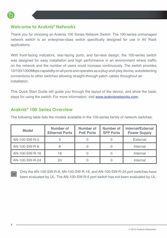
The following table lists the models available in the 100-series family of network switches.
Model Number of Ethernet Ports
Number of PoE Ports
Number of SFP Ports
Internal/External Power Supply
AN-100-SW-R-5 5 0 0 External
AN-100-SW-R-8 8 0 0 Internal
AN-100-SW-R-16 16 0 0 Internal
AN-100-SW-R-24 24 0 0 Internal
Only the AN-100-SW-R-8, AN-100-SW-R-16, and AN-100-SW-R-24 port switches have been evaluated by UL. The AN-100-SW-R-5 port switch has not been evaluated by UL.
www.araknisnetworks.com | Support: 866.838.5052
5
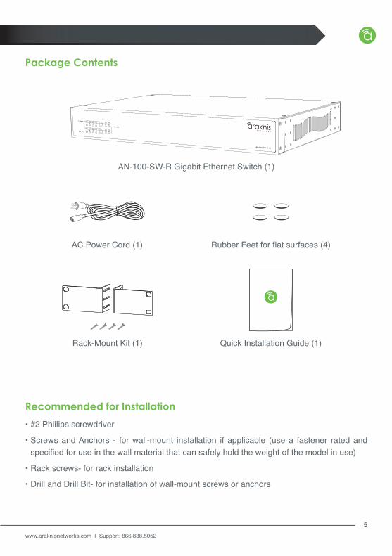
Package Contents
Recommended for Installation
• #2 Phillips screwdriver
• Screws and Anchors - for wall-mount installation if applicable (use a fastener rated and specified for use in the wall material that can safely hold the weight of the model in use)
• Rack screws- for rack installation
• Drill and Drill Bit- for installation of wall-mount screws or anchors
AN-100-SW-R Gigabit Ethernet Switch (1)
AC Power Cord (1) Rubber Feet for flat surfaces (4)
Quick Installation Guide (1)Rack-Mount Kit (1)

© 2013 Araknis Networks®
6
Rack Mounting
or
AN-100-SW-R-16
13
57
911
1315
24
68
1012
1416
1 Gbps
Link/Act
AN-100-SW-R-16
13
57
911
1315
24
68
1012
1416
1 Gbps
Link/Act
Mounting Options
Standard Protruding Recessed
www.araknisnetworks.com | Support: 866.838.5052
7
13
57
911
1315
24
68
1012
1416
Link/Act
1 Gbps
AN-100-SW-R-16
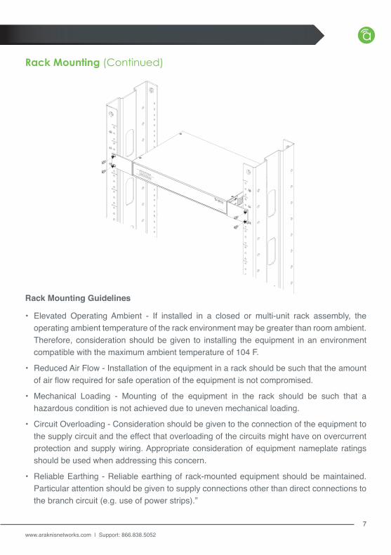
Rack Mounting (Continued)
• Elevated Operating Ambient - If installed in a closed or multi-unit rack assembly, the operating ambient temperature of the rack environment may be greater than room ambient. Therefore, consideration should be given to installing the equipment in an environment compatible with the maximum ambient temperature of 104 F.
• Reduced Air Flow - Installation of the equipment in a rack should be such that the amount of air flow required for safe operation of the equipment is not compromised.
• Mechanical Loading - Mounting of the equipment in the rack should be such that a hazardous condition is not achieved due to uneven mechanical loading.
• Circuit Overloading - Consideration should be given to the connection of the equipment to the supply circuit and the effect that overloading of the circuits might have on overcurrent protection and supply wiring. Appropriate consideration of equipment nameplate ratings should be used when addressing this concern.
• Reliable Earthing - Reliable earthing of rack-mounted equipment should be maintained. Particular attention should be given to supply connections other than direct connections to the branch circuit (e.g. use of power strips).”
Rack Mounting Guidelines

© 2013 Araknis Networks®
8
Wall Mounting
ON 100-240V AC
OFF 50-60Hz
1
35
7
911
1315
24
68
1012
1416
Shelf Mounting
Caution: Do not stack more than 4 switches together. Do not stack any other equipment on top of the network switch to avoid possible interference or damage.
For wall mounting, we recommend using 4 drywall screws, minimum of 1-1/4” X 8 GA with anchors
AN-100-SW-R-16
13
57
9111315 24
6810121416
1 Gbps
Link/Act
www.araknisnetworks.com | Support: 866.838.5052
9
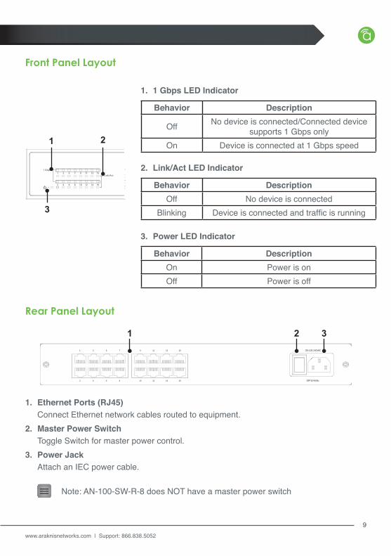
Behavior DescriptionOn Power is onOff Power is off
3. Power LED Indicator
Behavior Description
Off No device is connected/Connected device supports 1 Gbps only
On Device is connected at 1 Gbps speed
1. 1 Gbps LED Indicator
Behavior DescriptionOff No device is connected
Blinking Device is connected and traffic is running
2. Link/Act LED Indicator1 3 5 7 9 11 13 15
2 4 6 8 10 12 14 16
Link/Act
1 Gbps
1 2
3
Front Panel Layout
Rear Panel Layout
ON 100-240VAC
OFF 50-60Hz
1 3 5 7 9 11 13 15
2 4 6 8 10 12 14 16
1 2 3
1. Ethernet Ports (RJ45) Connect Ethernet network cables routed to equipment.2. Master Power Switch Toggle Switch for master power control.3. Power Jack Attach an IEC power cable.
Note: AN-100-SW-R-8 does NOT have a master power switch
© 2013 Araknis Networks®
10
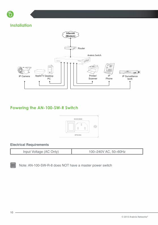
Installation
Powering the AN-100-SW-R Switch
Router
Araknis Switch
DesktopPC
IP Camera Printer/Scanner
IP SurveillanceNVR
IPPhone
AppleTV
Internet(Modem)
ON 100-240VAC
OFF 50-60Hz
1 3 5 7 9 11 13 15
2 4 6 8 10 12 14 16
Input Voltage (AC Only) 100~240V AC, 50~60Hz
Electrical Requirements
Note: AN-100-SW-R-8 does NOT have a master power switch
www.araknisnetworks.com | Support: 866.838.5052
11
Warranty
Contacting Technical Support
2 Year Limited WarrantyAraknis Networks® products have a 2-Year Limited Warranty. This warranty includes parts and labor repairs on all components found to be defective in material or workmanship under normal conditions of use. This warranty shall not apply to products which have been abused, modified or disassembled. Products to be repaired under this warranty must be returned to SnapAV or a designated service center with prior notification and an assigned return authorization number (RA).
Phone: (866) 838-5052Email: [email protected]

131021-1729© 2013 Araknis Networks®


