10MHz GPS Disciplined Oscillator
By Adam Maurer, VK4CP/VK4GHZ Rev 1.0 May 2011
Introduction
This document describes using a surplus Trimble Thunderbolt GPS Disciplined Oscillator as a precision
10MHz reference source for a multi-transverter PLL Local Oscillator system, or for use as a master shack
reference, which can be used as a reference for a frequency counter, spectrum analyzer, and even your
transceivers.
Whilst there are many possibilities with enclosures and layout, this article brings to your attention the use of
an inexpensive DC-DC converter board to generate +5 and -12V rails, and an easy to construct 10MHz
Splitter/Amp kit that provides four isolated and filtered outputs.
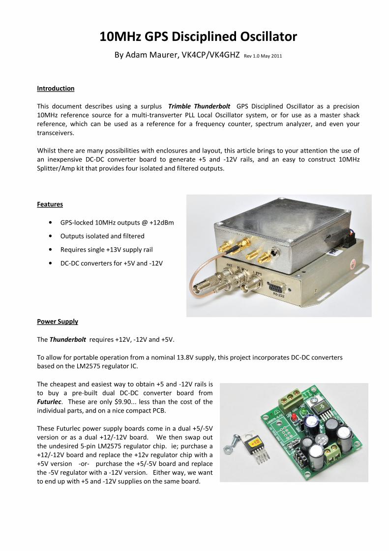
Features
• GPS-locked 10MHz outputs @ +12dBm
• Outputs isolated and filtered
• Requires single +13V supply rail
• DC-DC converters for +5V and -12V
Power Supply
The Thunderbolt requires +12V, -12V and +5V.
To allow for portable operation from a nominal 13.8V supply, this project incorporates DC-DC converters
based on the LM2575 regulator IC.
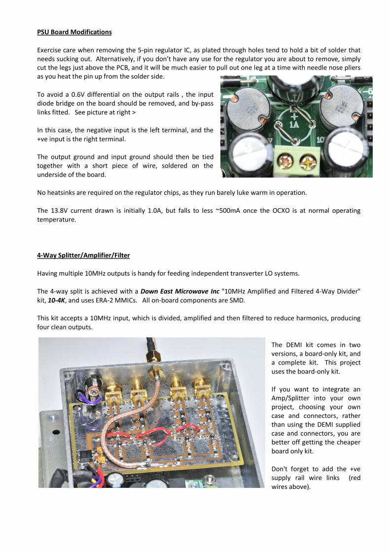
The cheapest and easiest way to obtain +5 and -12V rails is
to buy a pre-built dual DC-DC converter board from
Futurlec. These are only $9.90... less than the cost of the
individual parts, and on a nice compact PCB.
These Futurlec power supply boards come in a dual +5/-5V
version or as a dual +12/-12V board. We then swap out
the undesired 5-pin LM2575 regulator chip. ie; purchase a
+12/-12V board and replace the +12v regulator chip with a
+5V version -or- purchase the +5/-5V board and replace
the -5V regulator with a -12V version. Either way, we want
to end up with +5 and -12V supplies on the same board.
PSU Board Modifications
Exercise care when removing the 5-pin regulator IC, as plated through holes tend to hold a bit of solder that
needs sucking out. Alternatively, if you don’t have any use for the regulator you are about to remove, simply
cut the legs just above the PCB, and it will be much easier to pull out one leg at a time with needle nose pliers
as you heat the pin up from the solder side.
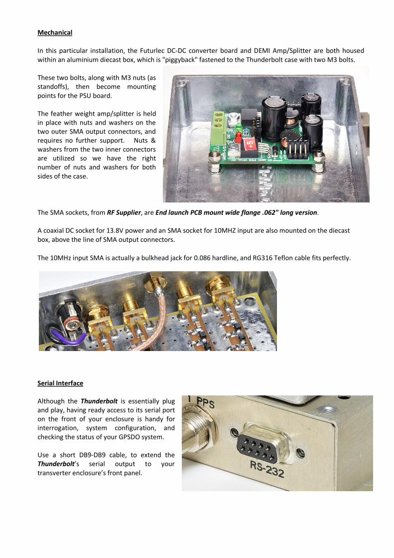
To avoid a 0.6V differential on the output rails , the input
diode bridge on the board should be removed, and by-pass
links fitted. See picture at right >
In this case, the negative input is the left terminal, and the
+ve input is the right terminal.
The output ground and input ground should then be tied
together with a short piece of wire, soldered on the
underside of the board.
No heatsinks are required on the regulator chips, as they run barely luke warm in operation.
The 13.8V current drawn is initially 1.0A, but falls to less ~500mA once the OCXO is at normal operating
temperature.
4-Way Splitter/Amplifier/Filter
Having multiple 10MHz outputs is handy for feeding independent transverter LO systems.
The 4-way split is achieved with a Down East Microwave Inc "10MHz Amplified and Filtered 4-Way Divider"
kit, 10-4K, and uses ERA-2 MMICs. All on-board components are SMD.
This kit accepts a 10MHz input, which is divided, amplified and then filtered to reduce harmonics, producing
four clean outputs.
The DEMI kit comes in two
versions, a board-only kit, and
a complete kit. This project
uses the board-only kit.
If you want to integrate an
Amp/Splitter into your own
project, choosing your own
case and connectors, rather
than using the DEMI supplied
case and connectors, you are
better off getting the cheaper
board only kit.
Don't forget to add the +ve
supply rail wire links (red
wires above).
Mechanical
In this particular installation, the Futurlec DC-DC converter board and DEMI Amp/Splitter are both housed
within an aluminium diecast box, which is "piggyback" fastened to the Thunderbolt case with two M3 bolts.
These two bolts, along with M3 nuts (as
standoffs), then become mounting
points for the PSU board.
The feather weight amp/splitter is held
in place with nuts and washers on the
two outer SMA output connectors, and
requires no further support. Nuts &
washers from the two inner connectors
are utilized so we have the right
number of nuts and washers for both
sides of the case.
The SMA sockets, from RF Supplier, are End launch PCB mount wide flange .062" long version.
A coaxial DC socket for 13.8V power and an SMA socket for 10MHZ input are also mounted on the diecast
box, above the line of SMA output connectors.
The 10MHz input SMA is actually a bulkhead jack for 0.086 hardline, and RG316 Teflon cable fits perfectly.
Serial Interface
Although the Thunderbolt is essentially plug
and play, having ready access to its serial port
on the front of your enclosure is handy for
interrogation, system configuration, and
checking the status of your GPSDO system.
Use a short DB9-DB9 cable, to extend the
Thunderbolt’s serial output to your
transverter enclosure’s front panel.

Thunderbolt Power Connector
Pin Description Purpose
1 +12V Prime voltage for the OCXO
2 Ground Power ground
3 +5V Load share voltage, Logic & IO
4 +5V Load share voltage, Logic & IO
5 Ground Power ground
6 -12V Prime voltage for the OCXO
Power to the Thunderbolt is fed via a hole
drilled into into the side of the diecast case.
Flyingbest supplies a power connector with a
short wiring harness with the Thunderbolt
unit.
The power connector has 0.1" pitch pins.
It has been noted that actual wire colours
may vary from unit to unit, so be alert when
wiring up.
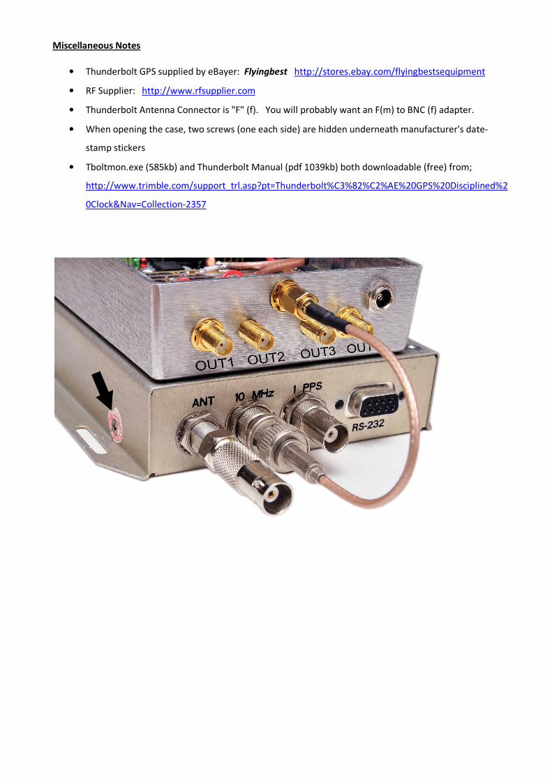
Above: RG316 with BNC (m) to SMA (m) interconnects the Thunderbolt to the Splitter/Amp
Bills of Material
Item QTY Vendor
Trimble Thunderbolt GPSDO eBay: Flyingbest
Dual +12/-12DC-DC converter board Futurlec, # MINIPOWERDUAL12V
LM2575 +5V regulator 1 Futurlec, RS
10MHz Amp & Filter board kit 1 Down East Microwave, # 10-4K
Aluminium Diecast box 1 Jaycar, # HB5607
M3x15mm bolts, washers & nuts Jaycar
SMA (f) long PCB jacks 4 RF Supplier
SMA (f) bulkhead jack for .086 1 RF Supplier
RG316 Not much RF Supplier
BNC (m) for RG316/LMR100 1 RF Supplier
SMA (m) for RG316/LMR100 1 RF Supplier
2.5mm DC bulkhead jack 1 Jaycar
GPS Timing Antenna , weatherproof, 5m, BNC 1 RF Supplier, # GA09-50-B01SP4
Thunderbolt Monitor
Using the TBoltmon.exe program, we can use a PC (via a serial port) to interrogate the Thunderbolt, and
manually setup and change the configuration. Annoyingly, you need to select the COM port each time you
run TBoltmon.exe. Later model PCs and laptops generally do not have COM serial ports, but inexpensive USB
to COM adapters are available from computer stores and eBay.
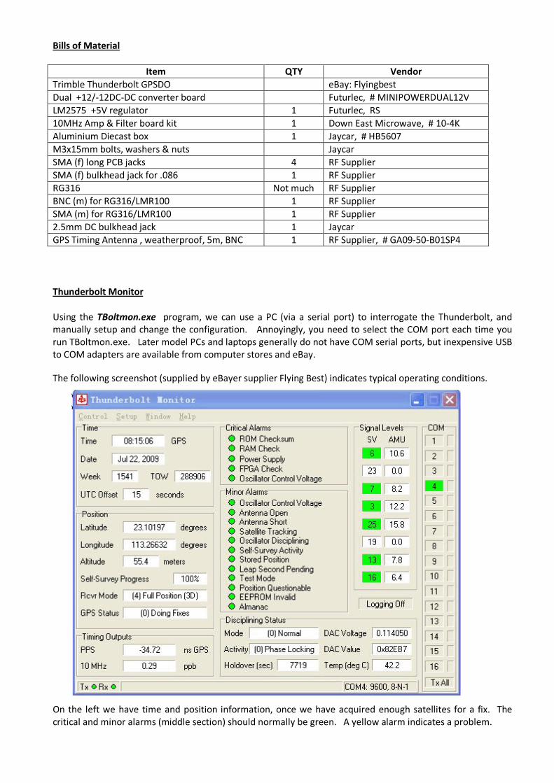
The following screenshot (supplied by eBayer supplier Flying Best) indicates typical operating conditions.
On the left we have time and position information, once we have acquired enough satellites for a fix. The
critical and minor alarms (middle section) should normally be green. A yellow alarm indicates a problem.
On the right, the relative signal levels of the GPS satellites (referred to as “SV” for Space Vehicles) is shown,
and in this example, six satellites are being received. The configuration setup allows us to ignore any satellites
that are weaker than a specified “AMU” level, and this can help reduce errors in timing with marginal
satellites being ignored.
For our purposes, the disciplining status of the 10MHz oscillator should be “normal” and “phase locking”.
Your Thunderbolt will probably be set to GPS time, and there is currently a 15 second offset between GPS
and UTC time.
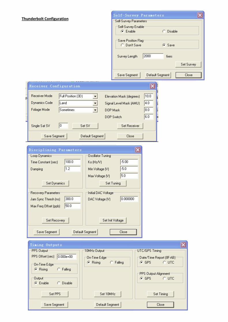
When your Thunderbolt is in a locked and stable condition (with 0.00ppb error), it is worth noting the DAC
Voltage. Enter that voltage in the Initial DAC Voltage in the GPS Disciplining Parameter setup, and “Save
Segment”. Given this known good starting point, it will help stabilize your GPSDO faster, the next time you
power up.
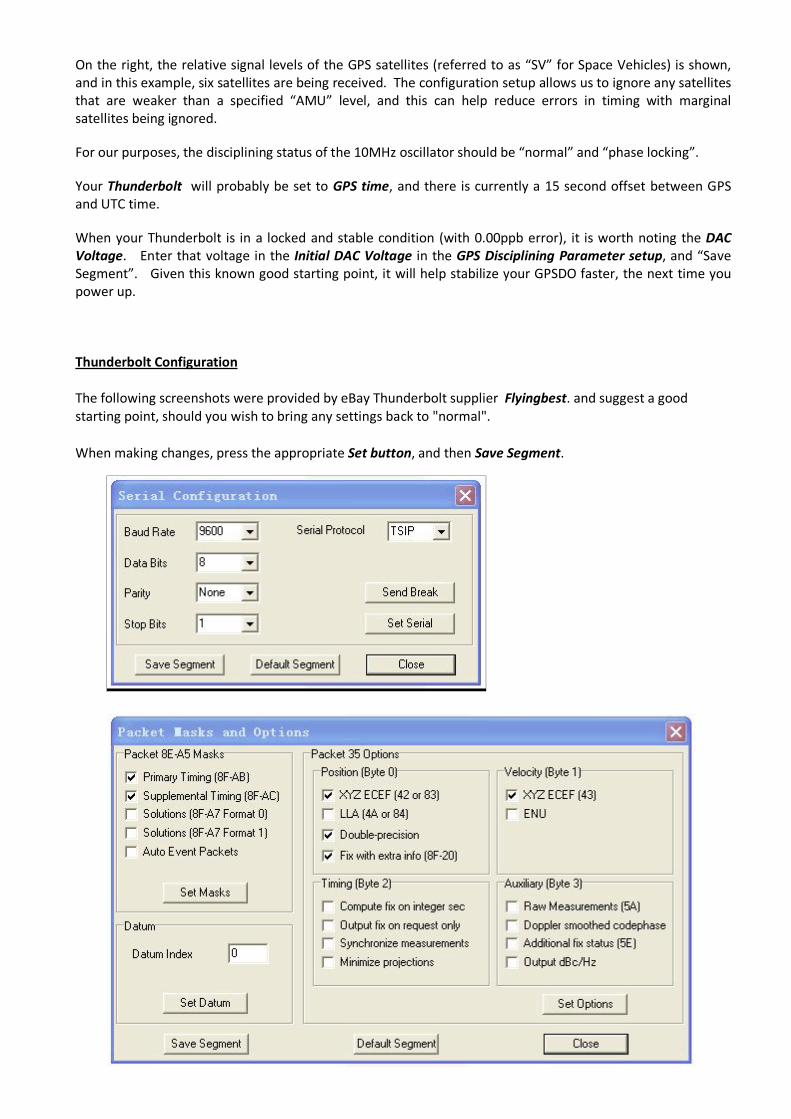
Thunderbolt Configuration
The following screenshots were provided by eBay Thunderbolt supplier Flyingbest. and suggest a good
starting point, should you wish to bring any settings back to "normal".
When making changes, press the appropriate Set button, and then Save Segment.
Thunderbolt Configuration
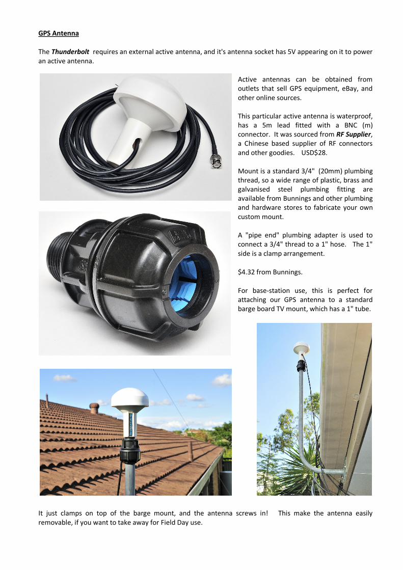
GPS Antenna
The Thunderbolt requires an external active antenna, and it's antenna socket has 5V appearing on it to power
an active antenna.
Active antennas can be obtained from
outlets that sell GPS equipment, eBay, and
other online sources.
This particular active antenna is waterproof,
has a 5m lead fitted with a BNC (m)
connector. It was sourced from RF Supplier,
a Chinese based supplier of RF connectors
and other goodies. USD$28.
Mount is a standard 3/4" (20mm) plumbing
thread, so a wide range of plastic, brass and
galvanised steel plumbing fitting are
available from Bunnings and other plumbing
and hardware stores to fabricate your own
custom mount.
A "pipe end" plumbing adapter is used to
connect a 3/4" thread to a 1" hose. The 1"
side is a clamp arrangement.
$4.32 from Bunnings.
For base-station use, this is perfect for
attaching our GPS antenna to a standard
barge board TV mount, which has a 1" tube.
It just clamps on top of the barge mount, and the antenna screws in! This make the antenna easily
removable, if you want to take away for Field Day use.
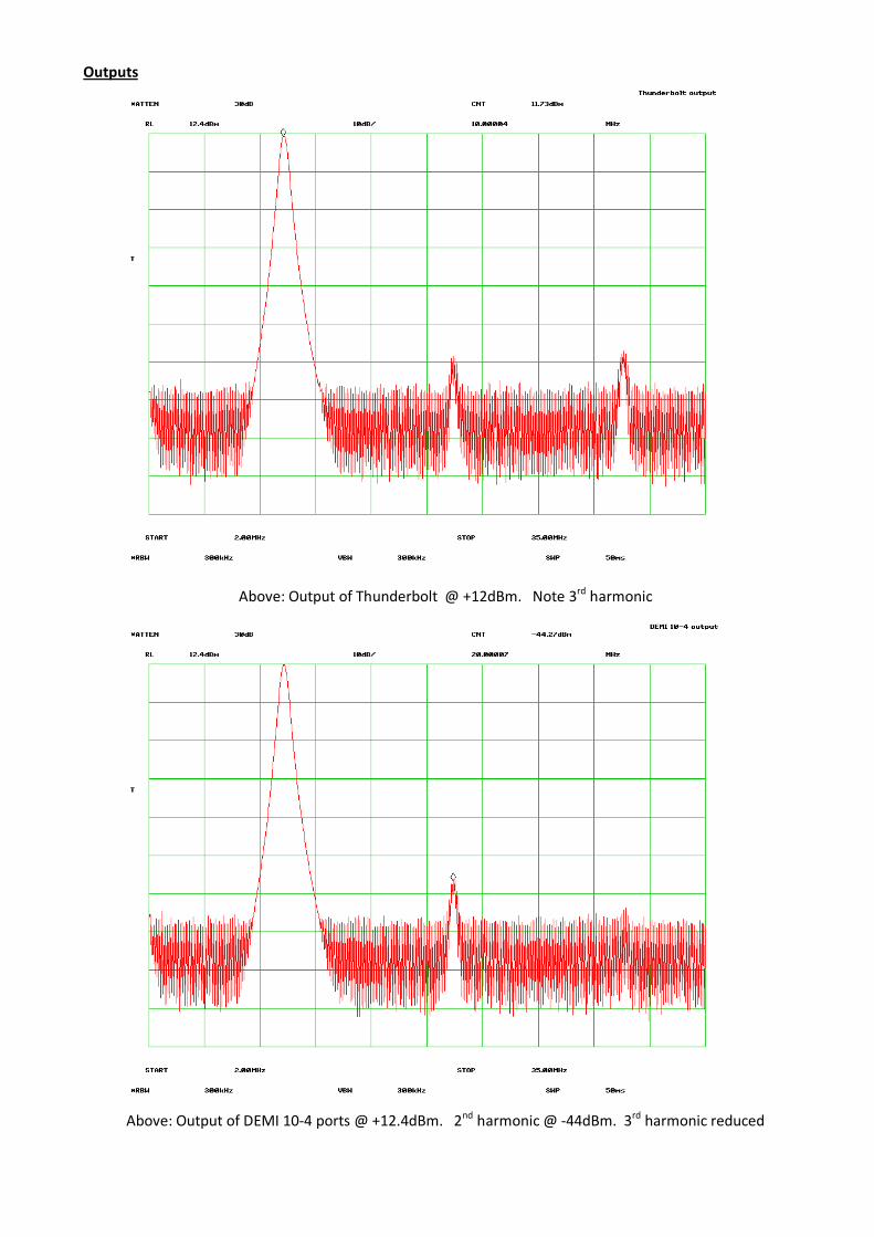
Outputs
Above: Output of Thunderbolt @ +12dBm. Note 3rd harmonic
Above: Output of DEMI 10-4 ports @ +12.4dBm. 2nd harmonic @ -44dBm. 3rd harmonic reduced
Miscellaneous Notes
• Thunderbolt GPS supplied by eBayer: Flyingbest http://stores.ebay.com/flyingbestsequipment
• RF Supplier: http://www.rfsupplier.com
• Thunderbolt Antenna Connector is "F" (f). You will probably want an F(m) to BNC (f) adapter.
• When opening the case, two screws (one each side) are hidden underneath manufacturer's date-
stamp stickers
• Tboltmon.exe (585kb) and Thunderbolt Manual (pdf 1039kb) both downloadable (free) from;
http://www.trimble.com/support_trl.asp?pt=Thunderbolt%C3%82%C2%AE%20GPS%20Disciplined%2
0Clock&Nav=Collection-2357


