
CR TYPE- Standard Curved Roller Cage -
part number structure
part number
CR2- 50- 7ZCR2- 60-12ZCR2- 70-10ZCR2- 87-10ZCR2-103-10ZCR2-120- 9ZCR3- 85-10ZCR3- 90-11ZCR3-110-10ZCR3-125-16ZCR3-160-14Z
A
t
W
D
a°p°
center radius
2
3
size
CR type
example CR 3 110
center radius
10Z
number of rollers
-
roller diameterD
mm
center radiusA
mmt
mmw
mm p° a° applicable
type
50 60 70 87103120 85 90110125160
0.3
0.4
5.6
7.2
4.6° 3.8° 3.3° 2.6° 2.2° 1.9° 3.4° 3.2° 2.6° 2.3° 1.8°
2.9° 2.4° 2.0° 1.6° 1.4° 1.2° 2.0° 1.9° 1.5° 1.3° 1.0°
RVRVRVFRVFRVFRVFRVFRV
RVF、RVRVF
RVF、RV
-
ACTUATOR
ACTUATORADVANTAGES ・・・・・・・・・・・・・・・・・ H-3PART NUMBER STRUCTURE ・・ H-4SPECIFICATIONS ・・・・・・・・・・・・・・ H-6ALLOWABLE SPEED AND STROKE LIMIT H-7ACCURACY ・・・・・・・・・・・・・・・・・・・ H-8RATED LIFE ・・・・・・・・・・・・・・・・・・・ H-10DIMENSION TABLE ・・・・・・・・・・・・ H-14〜29MOTOR BRACKET CONFIGURATIONS & APPLICABLE MOTORS H-30EXPOSED BRACKET R0 ・・・・・・・ H-43RETURN PULLEY UNIT ・・・・・・・ H-46LOW HOUSING ・・・・・・・・・・・・・・・・ H-48BELLOWS ・・・・・・・・・・・・・・・・・・・・・ H-50SENSOR ・・・・・・・・・・・・・・・・・・・・・・・ H-59PNP SENSOR ・・・・・・・・・・・・・・・・・ H-70SENSOR SPECIFICATIONS ・・・・ H-71POSITIONING PIN HOLE ・・・・・・・ H-74LUBRICATION ・・・・・・・・・・・・・・・・・ H-79OPERATING TEMPERATURE ・・ H-79USE AND HANDLING PRECAUTIONS H-79
G-70
GONIO WAYA
CTU
ATO
R
H-1
AC
TUA
TOR
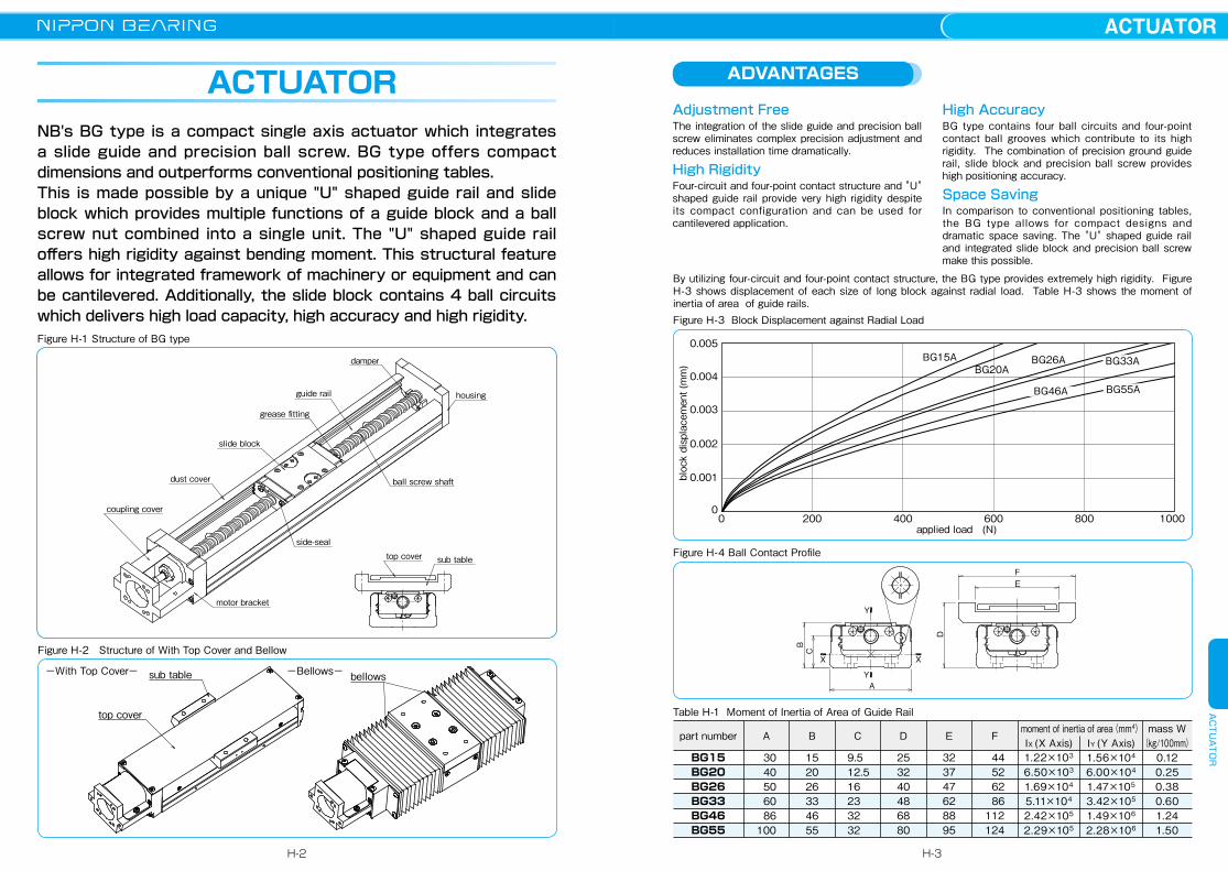
NB's BG type is a compact single axis actuator which integrates a slide guide and precision ball screw. BG type offers compact dimensions and outperforms conventional positioning tables. This is made possible by a unique "U" shaped guide rail and slide block which provides multiple functions of a guide block and a ball screw nut combined into a single unit. The "U" shaped guide rail offers high rigidity against bending moment. This structural feature allows for integrated framework of machinery or equipment and can be cantilevered. Additionally, the slide block contains 4 ball circuits which delivers high load capacity, high accuracy and high rigidity.
Adjustment FreeThe integration of the slide guide and precision ball screw eliminates complex precision adjustment and reduces installation time dramatically.
High RigidityFour-circuit and four-point contact structure and "U" shaped guide rail provide very high rigidity despite its compact configuration and can be used for cantilevered application.
High AccuracyBG type contains four ball circuits and four-point contact ball grooves which contribute to its high rigidity. The combination of precision ground guide rail, slide block and precision ball screw provides high positioning accuracy.
Space SavingIn comparison to conventional positioning tables, the BG type allows for compact designs and dramatic space saving. The "U" shaped guide rail and integrated slide block and precision ball screw make this possible.
ACTUATOR
Figure H-1 Structure of BG type
motor bracket
housing
side-seal
ball screw shaft
slide block
coupling cover
guide rail
dust cover
damper
top cover sub table
grease fitting
ADVANTAGES
Figure H-2 Structure of With Top Cover and Bellow
sub table
top cover
bellows−With Top Cover− −Bellows−
By utilizing four-circuit and four-point contact structure, the BG type provides extremely high rigidity. Figure H-3 shows displacement of each size of long block against radial load. Table H-3 shows the moment of inertia of area of guide rails.Figure H-3 Block Displacement against Radial Load
10008006004002000applied load (N)
block displacement (mm)
0.005
0.004
0.003
0.002
0.001
0
BG55ABG46A
BG33ABG20A
BG15A BG26A
Figure H-4 Ball Contact Profile
X X
Y
Y
B
A
C
D
EF
moment of inertia of area(mm4)IX (X Axis) IY (Y Axis)
part number A B C D E Fmass W
(kg/100mm) 30 40 50 60 86100
152026334655
9.512.516233232
253240486880
323747628895
44 52 62 86112124
1.22×10³
6.50×10³
1.69×10⁴
5.11×10⁴
2.42×10⁵
2.29×10⁵
1.56×10⁴
6.00×10⁴
1.47×10⁵
3.42×10⁵
1.49×10⁶
2.28×10⁶
0.120.250.380.601.241.50
BG15BG20BG26BG33BG46BG55
Table H-1 Moment of Inertia of Area of Guide Rail
H-2
ACTUATORACTUATOR
H-3
PART NUMBER STRUCTURE
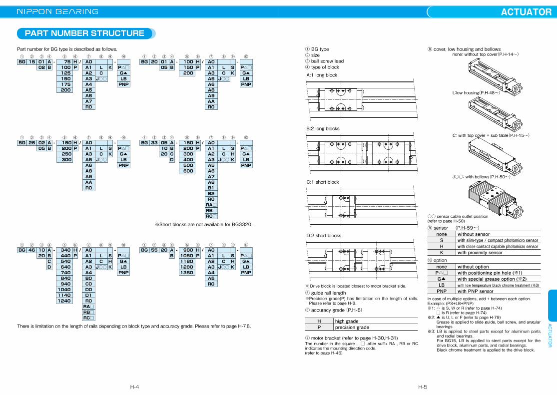
① BG type② size③ ball screw lead④ type of block
⑧ cover, low housing and bellows
※ Drive block is located closest to motor bracket side.
⑤ guide rail length※Precision grade(P) has limitation on the length of rails.
Please refer to page H-8.
⑥ accuracy grade(P.H-8)
⑦ motor bracket (refer to page H-30,H-31)The number in the square , □ ,after suffix RA , RB or RC indicates the mounting direction code. (refer to page H-46)
HP
high gradeprecision grade
○○ sensor cable outlet position(refer to page H-50)
⑨ sensor (P.H-59〜)
⑩ option
In case of multiple options, add + between each option.Example: (PS+LB+PNP)※1: △ is S, W or R (refer to page H-74) □ is R (refer to page H-74)※2: ▲ is U, L or F (refer to page H-79)
Grease is applied to slide guide, ball screw, and angular bearings.
※3: LB is applied to steel parts except for aluminum parts and radial bearings.For BG15, LB is applied to steel parts except for the drive block, aluminum parts, and radial bearings. Black chrome treatment is applied to the drive block.
noneSHK
without sensorwith slim-type / compact photomicro sensorwith close contact capable photomicro sensorwith proximity sensor
noneP△□G▲LB
PNP
without optionwith positioning pin hole (※1)with special grease option (※2)with low temperature black chrome treatment (※3)with PNP sensor
A:1 long block
B:2 long blocks
C:1 short block
D:2 short blocks
Part number for BG type is described as follows.
※Short blocks are not available for BG3320.
BG 15 A - 75 H / A0L
-01① ② ④ ⑤ ⑥ ⑦ ⑧ ⑨ ⑩③
B 100 P A1C
K P△□02125150175200
A2J○○
G▲A3 LBA4 PNPA5A6A7R0
BG 20 A - 100 H / A0L
-01① ② ④ ⑤ ⑥ ⑦ ⑧ ⑨ ⑩③
B 150 P A1C
S P△□05200 A3
J○○K G▲
A5 LBA6 PNPA8A9AAR0
BG 26 A - 150 H / A0L
-02① ② ④ ⑤ ⑥ ⑦ ⑧ ⑨ ⑩③
B 200 P A1C
S P△□05250 A3
J○○K G▲
A5 LBPNPA6
A8A9AAR0
300
BG 46 A - 340 H / A0L
-10① ② ④ ⑤ ⑥ ⑦ ⑧ ⑨ ⑩③
B 440 P A1C
S P△□20540 A2
J○○H G▲
A3 LBA4 PNPB0C0D0D1R0
640CD K
740840
RA□RB□RC□
940104011401240
BG 55 A - 980 H / A0L
-20① ② ④ ⑤ ⑥ ⑦ ⑧ ⑨ ⑩③
B 1080 P A1C
S P△□1180 A2
J○○H G▲
A3 LBA4A5
PNP
R0
1280 K1380
BG 33 A - 150 H / A0L
-05① ② ④ ⑤ ⑥ ⑦ ⑧ ⑨ ⑩③
B 200 P A1C
S P△□10300 A2
J○○H G▲
A3 LBA5 PNPA6
B1B2R0
400C20D K
500600
RA□RB□RC□
A7A8
L:ローハウジング(P.H-48~)
none: without top cover(P.H-14~)
L:low housing(P.H-48~)
C: with top cover + sub table(P.H-15~)
J○○: with bellows(P.H-50~)
There is limitation on the length of rails depending on block type and accuracy grade. Please refer to page H-7,8.
H-4
ACTUATORACTUATOR
H-5

ALLOWABLE SPEED AND STROKE LIMIT
Table H-2 Specifications
SPECIFICATIONS
BG Type is categorized as either high grade (H) or precision grade (P).Precision grade(P) has limitation on the length of rails. Please refer to page H-8.
M2P ,M2Y and M2R are the allowable static moments when 2 blocks are used in close contact.※ Please consult with NB when using BG15, BG20 and BG26 series in the Precision grade with short and frequent stroke. (short stroke: BG1501=
2mm or less, BG1502= 4mm or less, BG2001 = 7mm or less, BG2005 = 25mm or less, BG2602 = 14mm or less and BG2605 = 25mm or less)Short blocks are not available for BG3320.
Figure H-5 Direction of Moment
MY
MR M2RMP
M2Y
M2P
part numberprecision grade
radial clearance μmkNkNN・mN・mN・mN・mN・mN・mkNkNN・mN・mN・mN・mN・mN・mmmmm−kNkN−kNkN
basic dynamic load
basic static load
allowable static moment
basic dynamic load
basic static load
allowable static moment
C
CO
MP
M2P
MY
M2Y
MR
M2R
C
CO
MP
M2P
MY
M2Y
MR
M2R
long
blo
ckgu
ide
shor
t blo
ckbe
arin
g su
ppor
tba
ll sc
rew
shaft diameterleadspacer-ball ratiobasic dynamic loadbasic static load
Ca
Coa
basic dynamic loadbasic static load
Cb
Cob
part number
high−3〜0
high−2〜0
※precision
−6〜−3
※precision
−4〜−2
BG2001BG1501
high−3〜0
high−2〜0
※precision
−6〜−3
※precision
−4〜−2
BG2005BG1502 BG2602
※precision
−8〜−4high
−4〜0high
−4〜0
※precision
−8〜−4
BG2605 BG3305
※precision
−7〜−3high
−3〜0high
−3〜0
※precision
−7〜−3
BG3310 BG3320
※precision
−7〜−3high
−3〜0high
−5〜0
※precision
−11〜−5
BG4610 BG4620
※precision
−11〜−5high
−5〜0high
−6〜0
※precision
−18〜−6
BG5520
4.27
7.89
35
199
42
237
101
201
−
−
−
−
−
−
−
−
2.42
4.76
17
92
20
110
51
102
−
−
−
−
−
−
−
−
7.87
14.98
99
550
118
656
255
509
−
−
−
−
−
−
−
−
12.6
22.7
181
1,035
215
1,233
500
1,000
−
−
−
−
−
−
−
−
7.8
11.4
49
368
59
439
250
500
29.8
51.2
610
3,285
727
3,914
1,612
3,224
19.9
28.8
207
1,336
246
1,593
907
1,814
43.2
74.0
1,088
5,465
1,297
6,513
2,701
5,402
−
−
−
−
−
−
−
−
6
1 5
−
0.63 0.65
1.34 0.92
6
1 2
−
0.39 0.54
0.77 0.75
8
2 5
−
2.60 2.35
3.64 3.30
5 10
12
20
10
−
3.35
5.90
1:1
2.11
2.95
−
2.20
3.50
1:1
1.39
1.75
1:1
1.46
2.02
−
2.32
4.05
10 20
15
−
4.40
7.90
1:1
2.77
3.95
−
4.40
7.90
2:1
3.36
5.27
20
20
2:1
4.12
7.00
−
5.40
10.5
AC5-14DF
1.31
1.25
AC4-12DF
1.21
1.08
AC6-16DF
1.79
1.76
70M8DF/GMP5
4.40
4.36
7001T2DF/GMP5
6.77
7.45
7002T2DF/GMP5
7.74
9.50
Allowable speed of BG type is subject to the type of motor and operating conditions. The speed may also be limited by the critical speed of the ball screw. Use caution when operating at high speeds or using long rails.
Table H-3 ALLOWABLE SPEED AND STROKE LIMIT
Figure H-6 Guide Rail Length and Allowable Speed
BG2602BG1501
1400120010008006004002000
16001400120010008006004002000
allowable speed mm/sec
guide rail length mm
BG4620
BG4610BG3305
BG3310BG2005
BG2605
BG2001
BG3320
BG5520
BG1502
part number
part number
part number
part number
part number
part number
lead1
lead1
lead2
lead5
lead10
Short block type is not available for lead 20.
lead20
lead2
lead5
lead5
lead10
lead20
lead20
stroke limit(mm)
stroke limit(mm)
stroke limit(mm)
stroke limit(mm)
stroke limit(mm)
stroke limit(mm)
speed(mm/sec)
speed(mm/sec)
speed(mm/sec)
speed(mm/sec)
speed(mm/sec)
speed(mm/sec)
BG15
BG20
BG26
BG33
BG46
BG55
rail length 75100125150175200
rail length100150200
rail length150200250300
rail length150200300400500600
rail length 340 440 540 640 740 840 9401,0401,1401,240
rail length 9801,0801,1801,2801,380
1 long block 30 55 80105130155
1 long block 43 93143
1 long block 73123173223
1 long block 60110210310410510
1 long block 209 309 409 509 609 709 809 9091,0091,109
1 long block 834 9341,0341,1341,234
2 long blocks−−
46 71 96121
2 long blocks−
51101
2 long blocks−
61111161
2 long blocks−−
133233333433
2 long blocks 100 200 300 400 500 600 700 800 9001,000
2 long blocks 711 811 9111,0111,111
1 short block−−−−−−
1 short block−−−
1 short block−−−−
1 short block 85135235335435535
1 short block 245 345 445 545 645 745 845 9451,0451,145
1 short block −−−−−
2 short blocks−−−−−−
2 short blocks−−−
2 short blocks−−−−
2 short blocks 34 84184284384484
2 short blocks 172 272 372 472 572 672 772 872 9721,072
2 short blocks −−−−−
185
187
281
550
740
1,120 910 750 630 530
460310
650500390315260220
370
925
694
1,100
1,480
1,500
930 620
1,3001,000 780 630 520 440
H-6
ACTUATORACTUATOR
H-7
ACCURACY
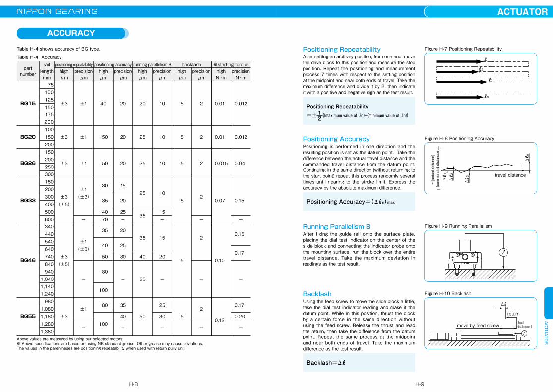
Table H-4 shows accuracy of BG type.
Table H-4 Accuracy
Above values are measured by using our selected motors.※ Above specifications are based on using NB standard grease. Other grease may cause deviations.The values in the parentheses are positioning repeatability when used with return pully unit.
Positioning RepeatabilityAfter setting an arbitrary position, from one end, move the drive block to this position and measure the stop position. Repeat the positioning and measurement process 7 times with respect to the setting position at the midpoint and near both ends of travel. Take the maximum difference and divide it by 2, then indicate it with a positive and negative sign as the test result.
Positioning AccuracyPositioning is performed in one direction and the resulting position is set as the datum point. Take the difference between the actual travel distance and the commanded travel distance from the datum point. Continuing in the same direction (without returning to the start point) repeat this process randomly several times until nearing to the stroke limit. Express the accuracy by the absolute maximum difference.
Running Parallelism BAfter fixing the guide rail onto the surface plate, placing the dial test indicator on the center of the slide block and connecting the indicator probe onto the mounting surface, run the block over the entire travel distance. Take the maximum deviation in readings as the test result.
BacklashUsing the feed screw to move the slide block a little, take the dial test indicator reading and make it the datum point. While in this position, thrust the block by a certain force in the same direction without using the feed screw. Release the thrust and read the return, then take the difference from the datum point. Repeat the same process at the midpoint and near both ends of travel. Take the maximum difference as the test result.
Positioning Repeatability12((maximum value of ℓn)−(minimum value of ℓn))
Positioning Accuracy=(Δℓn)max
Backlash=Δℓ
Figure H-7 Positioning Repeatability
ℓ1
ℓ2
ℓ3
ℓn
Figure H-8 Positioning Accuracy
+
-
= (actual distance)
-(commanded distance)
travel distance
Δℓ1
Δℓ2
Δℓ3
Δℓn
Figure H-9 Running Parallelism
Figure H-10 Backlash
move by feed screw thrust displacement
return
Δℓ
=±
part number
rail lengthmm
highμm
positioning repeatability
BG15
BG20
BG26
BG33
BG46
BG55
precisionμm
highμm
positioning accuracyprecision
μmhighμm
running parallelism Bprecision
μmprecision
μm
backlashhighμm
highN・m
※starting torqueprecision
N・m75
100125150175200100150200150200250300150200300400500600340440540640740840940
1,0401,1401,240
9801,0801,1801,2801,380
±3
±3
±3
±3(±5)
±3(±5)
±3
±1
±1
±1
±1(±3)
−
±1(±3)
−
±1
−
40
50
50
30
35
40 70
35
40
50
80
100
80
100
20
20
20
15
20
25−
20
25
30
−
35
40
−
20
25
25
25
35
35
40
50
50
10
10
10
10
15−
15
20
−
25
30
−
5
5
5
5
5
5
2
2
2
2
−
2
−
2
−
0.01
0.01
0.015
0.07
0.10
0.12
0.012
0.012
0.04
0.15
−
0.15
0.17
−
0.17
0.20
−
H-8
ACTUATORACTUATOR
H-9

RATED LIFE
To obtain the rated life of the BG type, calculate the rated life of the guide portion, ball screw portion and support bearing portion. Use the minimum value as the rated life of the BG type.
A. Life of Guide Portion Use the following equation for calculating the rated life of guide portion.
A.1. Calculation of PTBefore calculating the rated life using the equation (1), the calculated load applied to one block (PT) needs to be obtained in consideration of the moment load, etc. that will be actually applied.For rapidly-accelerating or short stroke motion, PT needs to be calculated with acceleration taken into consideration. The calculation of this acceleration will be carried out for the mass applied to BG. Obtain the calculated load during uniform motion, acceleration, and deceleration, and use the average value of the three as PT.For the calculation of PT, select an appropriate equation depending on the installation conditions of the guide.It is also possible to calculate PT without including the effect of acceleration by using the equation
“PT = PTC (see the equations (2), (5), and (8)). In this case, however, the obtained value is a rough approximation, so a selection with sufficient margin is recommended.
…………………………(1)LG=( fCfW・C
PT )3・50
LG: rated life(km) fC: contact coefficient(refer to Table H-5)fW: applied load coefficient(refer to Table H-6) C: basic dynamic load rating(N)PT: calculated load applied to one block(N)
number of blocks in close contact on one axis
12
contact coefficient(fC)
1.00.81
Table H-5 Contact Coefficient(fC)
operating conditions applied load coefficient(fW)vibration, impact
nonelowhigh
velocity0.25m/s or less
1m/s or less1m/s or more
1.0 〜 1.51.5 〜 2.02.0 〜 3.5
Table H-6 Applied Load Coefficient(fW)
Table H-7 Moment Equivalent Coefficient
A.1.a. PT for Horizontal Move (Horizontal Mounting)i)during uniform motion(PTC)
………………………………(2)PTC= 1n ・W+Ep・MpL+Ey・MyL+Er・MrL
W+m
X
Z
Yii)during acceleration(PTa)
………(3)PTa= 1n ・W+Ep(MpL+m・αa・Z)+Ey(MyL+m・αa・X)+Er・MrL
Note that the values of (MpL+m・αa・Z) and (MyL+m・αa・X) will be treated as 0 (zero) when the calculated value is negative.
iii)during deceleration(PTd)
………(4)PTd= 1n ・W+Ep(MpL+m・αd・Z)+Ey(MyL+m・αd・X)+Er・MrL
Note that the values of (MpL+m・αd・Z) and (MyL+m・αd・X) will be treated as 0 (zero) when the calculated value is negative.
PTC: calculated load applied to a block during uniform motion(N) PTa: calculated load applied to a block during accelerating(N)PTd: calculated load applied to a block during decelerating(N) n: number of blocks of BG W: applied load(N) m: carrying mass(kg) αa: acceleration during accelerating(m/sec2) αd: acceleration during decelerating(m/sec2)(the negative value)X: distance between the center of BG and the center of the carrying mass (mm) Y: distance between the center of BG and the center of the carrying mass(mm) Z: distance between the center of BG ball screw and the center of the carrying mass(mm)Ep: moment equivalent coefficient in the pitching direction (refer to Table H-7) Ey: moment equivalent coefficient in the yawing direction (refer to Table H-7) Er: moment equivalent coefficient in the rolling direction (refer to Table H-7)MpL: applied moment in the pitching direction(N・mm) MpL=W・YMyL: applied moment in the yawing direction(N・mm) MyL=0MrL: applied moment in the rolling direction(N・mm) MrL=W・X ※Refer to Fig.H-5 for the direction of moment.
A.1.b. PT for Horizontal Move (Wall Mounting)i)during uniform motion(PTC)
……………………………(5)PTC= 11.19・n・W+Ep・MpL+Ey・MyL+Er・MrL
XY
Z
W+m
ii)during acceleration(PTa)
……(6)PTa= 11.19・n・W+Ep(MpL+m・αa・Z)+Ey(MyL+m・αa・X)+Er・MrL
Note that the values of (MpL+m・αa・Z) and (MyL+m・αa・X) will be treated as 0 (zero) when the calculated value is negative.
iii)during deceleration(PTd)
……(7)PTd= 11.19・n・W+Ep(MpL+m・αd・Z)+Ey(MyL+m・αd・X)+Er・MrL
Note that the values of (MpL+m・αd・Z) and (MyL+m・αd・X) will be treated as 0 (zero) when the calculated value is negative.
Figure H-11
Figure H-12
In case of load coming from different direction other than the direction shown in the drawing W+m, please contact NB.
In case of load coming from different direction other than the direction shown in the drawing W+m, please contact NB.
※The E2 coefficient is for two blocks being used in close contact.
PTC: calculated load applied to a block during uniform motion (N) PTa: calculated load applied to a block during accelerating (N)PTd: calculated load applied to a block during decelerating (N) n: number of blocks of BG W: applied load (N) m: carrying mass (kg)αa: acceleration during accelerating (m/sec2) αd: acceleration during decelerating (m/sec2) (the negative value) X: distance between the center of BG and the center of the carrying mass (mm)Y: distance between the center of BG and the center of the carrying mass (mm) Z: distance between the center of BG ball screw and the center of the carrying mass (mm)Ep: moment equivalent coefficient in the pitching direction (refer to Table H-7) Ey: moment equivalent coefficient in the yawing direction (refer to Table H-7) Er: moment equivalent coefficient in the rolling direction (refer to Table H-7) MpL: applied moment in the pitching direction (N・mm) MpL=0MyL: applied moment in the yawing direction (N・mm) MyL=W・Y MrL: applied moment in the rolling direction (N・mm) MrL=W・Z ※Refer to Fig. H-5 for the direction of moment.
BG15**ABG15**BBG20**ABG20**BBG26**ABG26**BBG33**ABG33**BBG33**CBG33**DBG46**ABG46**BBG46**CBG46**DBG55**ABG55**B
Ep(E2p)2.82×10⁻¹
5.16×10⁻²
2.25×10⁻¹
3.98×10⁻²
1.51×10⁻¹
2.72×10⁻²
1.26×10⁻¹
2.20×10⁻²
2.31×10⁻¹
3.09×10⁻²
8.39×10⁻²
1.56×10⁻²
1.39×10⁻¹
2.15×10⁻²
6.80×10⁻²
1.35×10⁻²
Ey(E2y)2.37×10⁻¹
4.33×10⁻²
1.89×10⁻¹
3.34×10⁻²
1.27×10⁻¹
2.28×10⁻²
1.06×10⁻¹
1.84×10⁻²
1.94×10⁻¹
2.59×10⁻²
7.04×10⁻²
1.31×10⁻²
1.17×10⁻¹
1.81×10⁻²
5.71×10⁻²
1.14×10⁻²
Er(E2r)9.35×10⁻²
4.67×10⁻²
7.84×10⁻²
3.92×10⁻²
5.88×10⁻²
2.94×10⁻²
4.55×10⁻²
2.27×10⁻²
4.55×10⁻²
2.27×10⁻²
3.17×10⁻²
1.59×10⁻²
3.17×10⁻²
1.59×10⁻²
2.74×10⁻²
1.37×10⁻²
H-10
ACTUATORACTUATOR
H-11
…………………………(12)
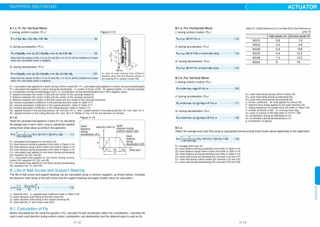
A.1.c. PT for Vertical Movei)during uniform motion(PTC)
…………………………………………(8)PTC=Ep・MpL+Ey・MyL+Er・MrL
Z
Y
W+m
Xii)during acceleration(PTa)
…………………(9)PTa=Ep(MpL+m・αa・Z)+Ey(MyL+m・αa・X)+Er・MrL
Note that the values of (MpL+m・αa・Z) and (MyL+m・αa・X) will be treated as 0 (zero) when the calculated value is negative.
iii)during deceleration(PTd)
………………(10)PTd=Ep(MpL+m・αd・Z)+Ey(MyL+m・αd・X)+Er・MrL
Note that the values of (MpL+m・αd・Z) and (MyL+m・αd・X) will be treated as 0 (zero) when the calculated value is negative.
Figure H-13
In case of load coming from different direction other than the direction shown in the drawing W+m, please contact NB.
A.1.d. Obtain the calculated load applied to a block (PT) by calculating the average load of each motion using an appropriate equation among those shown above according to the application.
PT= 1(S1+S2+S3)3
(PTa3・S1+PTC3・S2+PTd3・S3)……(11)
PT: calculated load applied to one block (N)S1: travel distance during acceleration (mm) (refer to Figure H-14)S2: travel distance during uniform motion (mm) (refer to Figure H-14)S3: travel distance during deceleration (mm) (refer to Figure H-14)PTa: calculated load applied to one block during accelerating (N) : equation (3), (6), and (9) PTC: calculated load applied to one block during uniform motion (N) : equation (2), (5), and (8)PTd: calculated load applied to one block during decelerating (N) : equation (4), (7), and (10)
Figure H-14
travel distanceduring acceleration (S1)
V
travel distance during uniform motion (S2)
travel distance during deceleration (S3)
TT1 T2 T3 time(sec)
velocity (mm/s)
0
B. Life of Ball Screw and Support BearingThe life of ball screw and support bearing can be calculated using a common equation, as shown below. Compare the dynamic load rating of the ball screw and the support bearing and apply smaller value for calculation.
La=( 1fW
・ )3・ℓCa or Cb
Pa
La: rated life (km) fW: applied load coefficient (refer to Table H-6)Ca: basic dynamic load rating of the ball screw (N) Cb: basic dynamic load rating of the support bearing (N)Pa: axial load (N) ℓ: ball screw lead (mm)
B.1. Calculation of PaBefore calculating the life using the equation (12), calculate Pa with acceleration taken into consideration. Calculate the load in each axial direction during uniform motion, acceleration, and deceleration and the obtained value is used as Pa.
PTC: calculated load applied to a block during uniform motion(N) PTa: calculated load applied to a block during accelerating(N)PTd: calculated load applied to a block during decelerating(N) n: number of blocks of BG W: applied load(N) m: carrying mass(kg) αa: acceleration during accelerating(m/sec2) αd: acceleration during decelerating(m/sec2) (the negative value)X: distance between the center of BG and the center of the carrying mass(mm)Y: distance between the center of BG and the center of the carrying mass(mm)Z: distance between the center of BG ball screw and the center of the carrying mass(mm)Ep: moment equivalent coefficient in the pitching direction (refer to Table H-7)Ey: moment equivalent coefficient in the yawing direction (refer to Table H-7)Er: moment equivalent coefficient in the rolling direction (refer to Table H-7)MpL: applied moment in the pitching direction (N・mm) MpL=W・Z MyL: loaded moment in the yawing direction (N・mm) MyL=W・XMrL: applied moment in the rolling direction (N・mm) MrL=0 ※Refer to Fig. H-5 for the direction of moment.
B.1.a. For Horizontal Move i)during uniform motion(Pac)
………………………………(13)Pac=μ・W+F+fb・n
ii)during acceleration(Paa)
……………(14)Paa=μ・W+F+fb・n+(m+mb・n)αa
iii)during deceleration(Pad)
……………(15)Pad=μ・W+F+fb・n+(m+mb・n)αd
B.1.b. For Vertical Movei)during uniform motion(Pac)
………………………(16)Pac=(m+mb・n)g+F+fb・n
ii)during acceleration(Paa)
……………(17)Paa=(m+mb・n)・(g+αa)+F+fb・n
iii)during deceleration(Pad)
……………(18)Pad=(m+mb・n)・(g+αd)+F+fb・n
B.1.c.Obtain the average axial load (Pa) using an appropriate formula among those shown above depending on the application.
Pa= 1(S1+S2+S3)3
…(19)(│Paa│3・S1+│Pac│3・S2+│Pad│3・S3)
Pac: axial load rating during uniform motion (N) Paa: axial load rating during accelerating (N) Pad: axial load rating during decelerating (N) μ: friction coefficient W: load applied to a block (N)F: external force (load) applied to the axial direction (N)fb: sliding resistance of a single block (N) (refer to Table H-8)n: number of blocks of BG m: carrying mass (kg)mb: mass of a block of BG (kg) (refer to P.H14〜29)αa: acceleration during accelerating (m/s2)αd: acceleration during decelerating (m/s2)g: acceleration of gravity
Pa: average axial load(N)S1: travel distance during acceleration (mm) (refer to Table H-14)S2: travel distance during uniform motion (mm) (refer to Table H-14)S3: travel distance during deceleration (mm) (refer to Table H-14)Paa: axial load during accelerating (N): formulas (14) and (17) Pac: axial load during uniform motion (N): formulas (13) and (16)Pad: axial load during decelerating (N): formulas (15) and (18)
Table H-8 Sliding Resistance (fb) of a Single Block (Seal Resistance) unit: N
BG15BG20BG26BG33BG46BG55
high grade (H) 0.8 2.3 5.4 4.4 7.4 9
precision grade (P) 1.8 4.9 9.8 10.2 13.3 16
H-12
ACTUATORACTUATOR
H-13
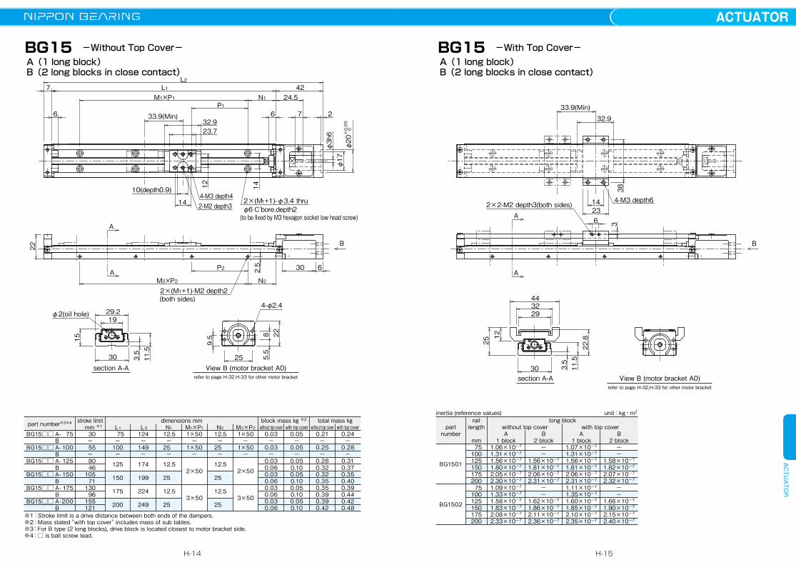
A(1 long block)B(2 long blocks in close contact)
BG15 -Without Top Cover-
View B (motor bracket A0)section A-Arefer to page H-32,H-33 for other motor bracket
+0.05
0
φ20
B
A
A
10(depth0.9)
14 2-M2 depth3
23.732.9
P1N1M1×P1
66
L1724.5
7
42
2
1412
L2
4-M3 depth4
φ3h6
22
P2
N2M2×P2
2.5 30 6
2×(M1+1)-M2 depth2(both sides)
φ17
2×(M1+1)-φ3.4 thruφ6 C'bore.depth2(to be fixed by M3 hexagon socket low head screw)
30
1929.2
33.9(Min)
φ2(oil hole)
15
3.511.5
25
9.5
5.5
8 22
4-φ2.4
View B (motor bracket A0)section A-Arefer to page H-32,H-33 for other motor bracket
B
A
A6
4-M3 depth614
38
23
33.9(Min)
32.9
293244
30
3
2×2-M2 depth3(both sides)
1225
3.511.522.8
A(1 long block)B(2 long blocks in close contact)
-With Top Cover-BG15
part number※3※4 stroke limit mm ※1 L1
dimensions mm block mass ㎏ ※2 total mass ㎏L2 N1 M1×P1 N2 M2×P2 without top cover with top cover without top cover with top cover
BG15□□ A- 75 BBG15□□ A- 100 BBG15□□ A- 125 BBG15□□ A- 150 BBG15□□ A- 175 BBG15□□ A- 200 B
30−
55−
80 46105 71130 96155121
75−
100−
125
150
175
200
124−
149−
174
199
224
249
12.5−
25−
12.5
25
12.5
25
1×50−
1×50−
2×50
3×50
12.5−
25−
12.5
25
12.5
25
1×50−
1×50−
2×50
3×50
0.03−
0.03−
0.030.060.030.060.030.060.030.06
0.05−
0.05−
0.050.100.050.100.050.100.050.10
0.21−
0.25−
0.280.320.320.350.350.390.390.42
0.24−
0.28−
0.310.370.350.400.390.440.420.48
※1:Stroke limit is a drive distance between both ends of the dampers.※2:Mass stated "with top cover" includes mass of sub tables.※3:For B type (2 long blocks), drive block is located closest to motor bracket side. ※4:□ is ball screw lead.
long blockpart
number
rail length
mmA
1 blockA
1 blockB
2 blockB
2 block
without top cover with top cover
inertia (reference values) unit:kg・m2
BG1501
BG1502
75100125150175200 75100125150175200
1.06×10⁻⁷
1.31×10⁻⁷
1.56×10⁻⁷
1.80×10⁻⁷
2.05×10⁻⁷
2.30×10⁻⁷
1.09×10⁻⁷
1.33×10⁻⁷
1.58×10⁻⁷
1.83×10⁻⁷
2.08×10⁻⁷
2.33×10⁻⁷
1.07×10⁻⁷
1.31×10⁻⁷
1.56×10⁻⁷
1.81×10⁻⁷
2.06×10⁻⁷
2.31×10⁻⁷
1.11×10⁻⁷
1.35×10⁻⁷
1.60×10⁻⁷
1.85×10⁻⁷
2.10×10⁻⁷
2.35×10⁻⁷
−−
1.56×10⁻⁷
1.81×10⁻⁷
2.06×10⁻⁷
2.31×10⁻⁷
−−
1.62×10⁻⁷
1.86×10⁻⁷
2.11×10⁻⁷
2.36×10⁻⁷
−−
1.58×10⁻⁷
1.82×10⁻⁷
2.07×10⁻⁷
2.32×10⁻⁷
−−
1.66×10⁻⁷
1.90×10⁻⁷
2.15×10⁻⁷
2.40×10⁻⁷
H-14
ACTUATORACTUATOR
H-15
2×2-M2 depth5(both sides)
8.5
4-M4 depth14
523734
3214
30
4.517
6
41.8(Min)
40.2
45
3320
40
View B (motor bracket A0)section A-A
B
A
A
refer to page H-34,H-35 for other motor bracket
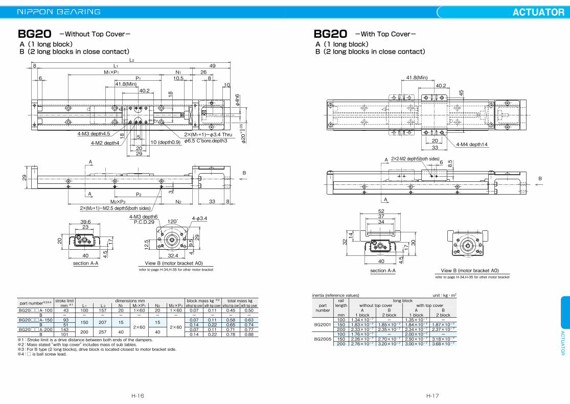
A(1 long block)B(2 long blocks in close contact)
BG20 -With Top Cover-
33
106
4.5
2×(M1+1)ーφ3.4 Thru φ6.5 C'bore.depth34-M2 depth4
4-M3 depth4.5
2×(M2+1)ーM2.5 depth5(both sides)
3
41.8(Min)
4-φ3.4
32.4
9.5
4
P.C.D.294-M3 depth6
120゚
29
12.5
φ4h6
20
40
39.6
17
23
8N2M2×P2P2
18
18
826
L2498
10.5
L1N1M1×P1
P1
2920
10 (depth0.9)5
40.2
View B (motor bracket A0)section A-A
B
A
A
+0.05
0
φ20
29
refer to page H-34,H-35 for other motor bracket
A(1 long block)B(2 long blocks in close contact)
BG20 -Without Top Cover-
part number※3※4 stroke limit mm ※1 L1
dimensions mm block mass ㎏ ※2 total mass ㎏L2 N1 M1×P1 N2 M2×P2 without top cover with top cover without top cover with top cover
BG20□□ A- 100 BBG20□□ A- 150 BBG20□□ A- 200 B
43−
93 51143101
100−
150
200
157−
207
257
20−
15
40
1×60−
2×60
20−
15
40
1×60−
2×60
0.07−
0.070.140.070.14
0.11−
0.110.220.110.22
0.45−
0.580.650.710.78
0.50−
0.630.740.770.88
※1:Stroke limit is a drive distance between both ends of the dampers.※2:Mass stated "with top cover" includes mass of sub tables.※3:For B type (2 long blocks), drive block is located closest to motor bracket side. ※4:□ is ball screw lead.
part number
rail length
mmA
1 blockA
1 blockB
2 blockB
2 block
without top cover with top coverlong block
BG2001
BG2005
100150200100150200
1.34×10⁻⁷
1.83×10⁻⁷
2.33×10⁻⁷
1.76×10⁻⁷
2.26×10⁻⁷
2.76×10⁻⁷
1.35×10⁻⁷
1.84×10⁻⁷
2.34×10⁻⁷
2.00×10⁻⁷
2.50×10⁻⁷
3.00×10⁻⁷
−1.85×10⁻⁷
2.35×10⁻⁷
−2.70×10⁻⁷
3.20×10⁻⁷
−1.87×10⁻⁷
2.37×10⁻⁷
−3.18×10⁻⁷
3.68×10⁻⁷
inertia (reference values) unit:kg・m2
H-16
ACTUATORACTUATOR
H-17

+0.05
0
φ24
BG26
34 8
25
4-φ3.4
P.C.D.334-M3 depth6
90゚2×(M2+1)ーM2.5 depth5(both sides)
37
16
13.5
3.8
42
26 22650
49.631
25
φ8 C'bore.depth4.52×(M1+1)ーφ4.5 Thru4-M4 depth7
4-M2 depth4
4
N2M2×P2P2
6 11 10
φ5h6
1030.5
4430
15 (depth0.9)8.5
L210 52L1
N1M1×P1P1
61.8(Min)60
A
A
View B (motor bracket A0)section A-A
B
refer to page H-36,H-37 for other motor bracket
37
A(1 long block)B(2 long blocks in close contact)
-Without Top Cover-
624743
55
38
2×2-M2 depth5(both sides)
4-M4 depth17
128.5
22650
4017
4430
61.8(Min)60
A
View B (motor bracket A0)section A-A
B
A
refer to page H-36,H-37 for other motor bracket
A(1 long block)B(2 long blocks in close contact)
-With Top Cover-BG26
part number
rail length
mmA
1 blockA
1 blockB
2 blockB
2 block
without top cover with top coverlong block
BG2602
BG2605
150200250300150200250300
6.08×10⁻⁷
7.65×10⁻⁷
9.22×10⁻⁷
1.08×10⁻⁶
6.99×10⁻⁷
8.56×10⁻⁷
1.01×10⁻⁶
1.17×10⁻⁶
6.16×10⁻⁷
7.73×10⁻⁷
9.29×10⁻⁷
1.09×10⁻⁶
7.44×10⁻⁷
9.01×10⁻⁷
1.06×10⁻⁶
1.21×10⁻⁶
−7.83×10⁻⁷
9.39×10⁻⁷
1.10×10⁻⁶
−9.63×10⁻⁷
1.12×10⁻⁶
1.28×10⁻⁶
−7.97×10⁻⁷
9.54×10⁻⁷
1.11×10⁻⁶
−1.05×10⁻⁶
1.21×10⁻⁶
1.37×10⁻⁶
part number※3※4 stroke limit mm ※1 L1
dimensions mm block mass ㎏ ※2 total mass ㎏L2 N1 M1×P1 N2 M2×P2 without top cover with top cover without top cover with top cover
BG26□□ A- 150 BBG26□□ A- 200 BBG26□□ A- 250 BBG26□□ A- 300 B
73−
123 61173111223161
150−
200
250
300
212−
262
312
362
35−
20
45
30
1×80−
2×80
3×80
35−
20
45
30
1×80−
2×80
3×80
0.17−
0.170.340.170.340.170.34
0.24−
0.240.480.240.480.240.48
0.93−
1.141.311.361.531.571.74
1.07−
1.31.541.531.781.762.01
※1:Stroke limit is a drive distance between both ends of the dampers.※2:Mass stated "with top cover" includes mass of sub tables.※3:For B type (2 long blocks), drive block is located closest to motor bracket side. ※4:□ is ball screw lead.
inertia (reference values) unit:kg・m2
H-18
ACTUATORACTUATOR
H-19
BG33
L2L18
6M1×P1
M2×P2
A
A P2N2
B
N1 34
109 9P177.2(Min)
77.274.4
30
59
4-M5 depth84-M2 depth5
8
3053.8
15 (depth1) 2×(M1+1)ーφ5.5 thruφ9.5 C'bore.depth5
2×(M2+1)ーM2.5 depth6(both sides)6
30
φ6h6
φ28H8
59
section A-A View B (motor bracket A0)refer to page H-38,H-39 for other motor bracket
37.4
60
33 31.5
8
44.5
2-M4 depth8
18
50
90°60°
P.C.D.404-M4 depth8
P.C.D.374-M3 depth8
44.5
23
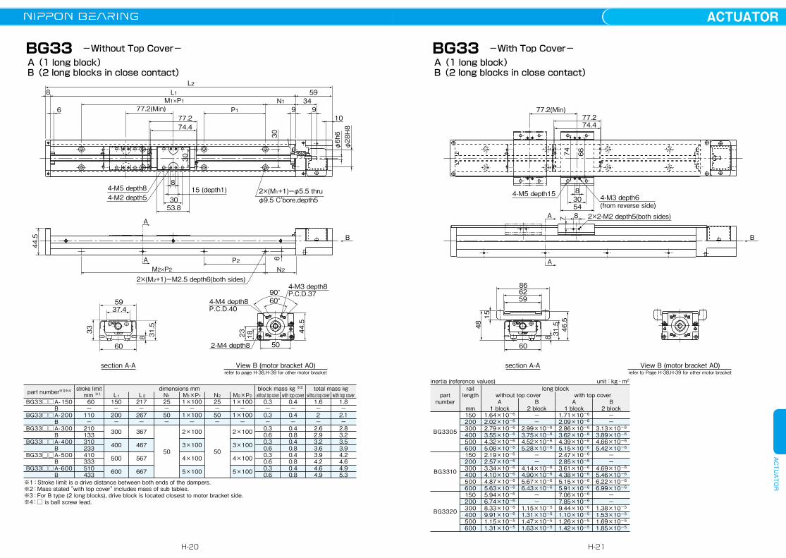
A(1 long block)B(2 long blocks in close contact)
-Without Top Cover-
77.2(Min)
54
830
4-M5 depth15 4-M3 depth6(from reverse side)
74 66
section A-A View B (motor bracket A0)refer to Page H-38,H-39 for other motor bracket
866259
60
48
31.5 46.5
15
8
77.274.4
2×2-M2 depth5(both sides)7 8
B
A
A
A(1 long block)B(2 long blocks in close contact)
-With Top Cover-BG33
part number
rail length
mmA
1 blockA
1 blockB
2 blockB
2 block
without top cover with top coverlong block
BG3305
BG3310
BG3320
150200300400500600150200300400500600150200300400500600
1.64×10⁻⁶
2.02×10⁻⁶
2.79×10⁻⁶
3.55×10⁻⁶
4.32×10⁻⁶
5.08×10⁻⁶
2.19×10⁻⁶
2.57×10⁻⁶
3.34×10⁻⁶
4.10×10⁻⁶
4.87×10⁻⁶
5.63×10⁻⁶
5.94×10⁻⁶
6.74×10⁻⁶
8.33×10⁻⁶
9.91×10⁻⁶
1.15×10⁻⁵
1.31×10⁻⁵
1.71×10⁻⁶
2.09×10⁻⁶
2.86×10⁻⁶
3.62×10⁻⁶
4.39×10⁻⁶
5.15×10⁻⁶
2.47×10⁻⁶
2.85×10⁻⁶
3.61×10⁻⁶
4.38×10⁻⁶
5.15×10⁻⁶
5.91×10⁻⁶
7.06×10⁻⁶
7.85×10⁻⁶
9.44×10⁻⁶
1.10×10⁻⁵
1.26×10⁻⁵
1.42×10⁻⁵
−−
2.99×10⁻⁶
3.75×10⁻⁶
4.52×10⁻⁶
5.28×10⁻⁶
−−
4.14×10⁻⁶
4.90×10⁻⁶
5.67×10⁻⁶
6.43×10⁻⁶
−−
1.15×10⁻⁵
1.31×10⁻⁵
1.47×10⁻⁵
1.63×10⁻⁵
−−
3.13×10⁻⁶
3.89×10⁻⁶
4.66×10⁻⁶
5.42×10⁻⁶
−−
4.69×10⁻⁶
5.46×10⁻⁶
6.22×10⁻⁶
6.99×10⁻⁶
−−
1.38×10⁻⁵
1.53×10⁻⁵
1.69×10⁻⁵
1.85×10⁻⁵
part number※3※4 stroke limit mm ※1 L1
dimensions mm block mass ㎏ ※2 total mass ㎏L2 N1 M1×P1 N2 M2×P2 without top cover with top cover without top cover with top cover
BG33□□ A- 150 BBG33□□ A- 200 BBG33□□ A- 300 BBG33□□ A- 400 BBG33□□ A- 500 BBG33□□ A- 600 B
60−
110−
210133310233410333510433
150−
200−
300
400
500
600
217−
267−
367
467
567
667
25−50−
50
1×100−
1×100−
2×100
3×100
4×100
5×100
25−50−
50
1×100−
1×100−
2×100
3×100
4×100
5×100
0.3−0.3−0.30.60.30.60.30.60.30.6
0.4−0.4−0.40.80.40.80.40.80.40.8
1.6−2−2.62.93.23.63.94.24.64.9
1.8−2.1−2.83.23.53.94.24.64.95.3
※1:Stroke limit is a drive distance between both ends of the dampers.※2:Mass stated "with top cover" includes mass of sub tables.※3:For B type (2 long blocks), drive block is located closest to motor bracket side. ※4:□ is ball screw lead.
inertia (reference values) unit:kg・m2
H-20
ACTUATORACTUATOR
H-21
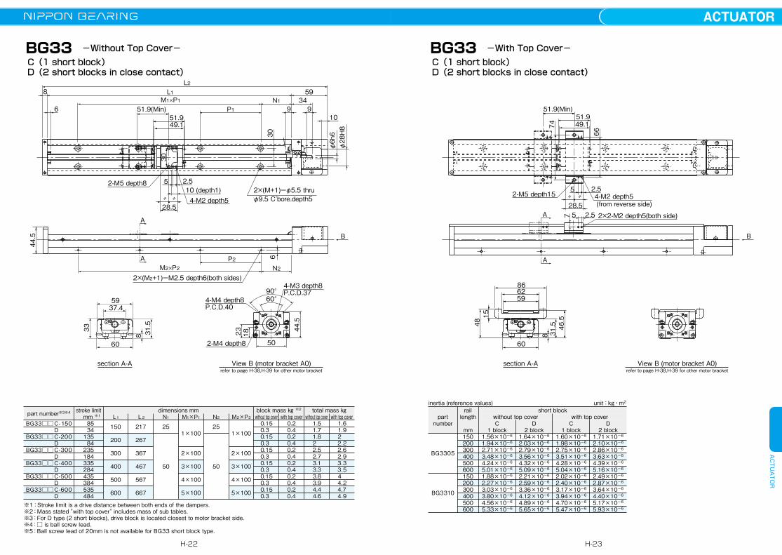
BG33C(1 short block)D(2 short blocks in close contact)
44.5
L2L18
6M1×P1
M2×P2
A
A P2N2
B
N1 34
109 9P1
59
2×(M+1)ーφ5.5 thru φ9.5 C'bore.depth5
2×(M2+1)ーM2.5 depth6(both sides)6
30
φ6h6
φ28H8
59
section A-A View B (motor bracket A0)refer to page H-38,H-39 for other motor bracket
37.4
60
33 31.5
8
〃 〃
51.9(Min)51.949.1
30
5
28.5
2.510 (depth1)
2-M5 depth8
4-M2 depth5
2-M4 depth8 50
90°60°
18
P.C.D.404-M4 depth8
P.C.D.374-M3 depth8
44.5
23
-Without Top Cover-
section A-A View B (motor bracket A0)refer to page H-38,H-39 for other motor bracket
866259
60
48
31.5 46.515
8
51.949.1
51.9(Min)
28.5
5 2.52-M5 depth15 4-M2 depth5
(from reverse side)
74
66
〃 〃
2×2-M2 depth5(both side)7 2.55
B
A
A
C(1 short block)D(2 short blocks in close contact)
-With Top Cover-BG33
part number※3※4 stroke limit mm ※1 L1
dimensions mm block mass ㎏ ※2 total mass ㎏L2 N1 M1×P1 N2 M2×P2 without top cover with top cover without top cover with top cover
BG33□□ C- 150 DBG33□□ C- 200 DBG33□□ C-300 DBG33□□ C- 400 DBG33□□ C- 500 DBG33□□ C- 600 D
85 34135 84235184335284435384535484
150
200
300
400
500
600
217
267
367
467
567
667
25
50
1×100
2×100
3×100
4×100
5×100
25
50
1×100
2×100
3×100
4×100
5×100
0.15 0.3 0.15 0.3 0.15 0.3 0.15 0.3 0.15 0.3 0.15 0.3
0.20.40.20.40.20.40.20.40.20.40.20.4
1.5 1.7 1.8 2 2.5 2.7 3.1 3.3 3.8 3.9 4.4 4.6
1.6 1.9 2 2.2 2.6 2.9 3.3 3.5 4 4.2 4.7 4.9
※1:Stroke limit is a drive distance between both ends of the dampers.※2:Mass stated "with top cover" includes mass of sub tables.※3:For D type (2 short blocks), drive block is located closest to motor bracket side. ※4:□ is ball screw lead.※5:Ball screw lead of 20mm is not available for BG33 short block type.
part number
rail length
mmC
1 blockC
1 blockD
2 blockD
2 block
without top cover with top covershort block
BG3305
BG3310
150200300400500600150200300400500600
1.56×10⁻⁶
1.94×10⁻⁶
2.71×10⁻⁶
3.48×10⁻⁶
4.24×10⁻⁶
5.01×10⁻⁶
1.88×10⁻⁶
2.27×10⁻⁶
3.03×10⁻⁶
3.80×10⁻⁶
4.56×10⁻⁶
5.33×10⁻⁶
1.60×10⁻⁶
1.98×10⁻⁶
2.75×10⁻⁶
3.51×10⁻⁶
4.28×10⁻⁶
5.04×10⁻⁶
2.02×10⁻⁶
2.40×10⁻⁶
3.17×10⁻⁶
3.94×10⁻⁶
4.70×10⁻⁶
5.47×10⁻⁶
1.64×10⁻⁶
2.03×10⁻⁶
2.79×10⁻⁶
3.56×10⁻⁶
4.32×10⁻⁶
5.09×10⁻⁶
2.21×10⁻⁶
2.59×10⁻⁶
3.36×10⁻⁶
4.12×10⁻⁶
4.89×10⁻⁶
5.65×10⁻⁶
1.71×10⁻⁶
2.10×10⁻⁶
2.86×10⁻⁶
3.63×10⁻⁶
4.39×10⁻⁶
5.16×10⁻⁶
2.49×10⁻⁶
2.87×10⁻⁶
3.64×10⁻⁶
4.40×10⁻⁶
5.17×10⁻⁶
5.93×10⁻⁶
inertia (reference values) unit:kg・m2
H-22
ACTUATORACTUATOR
H-23
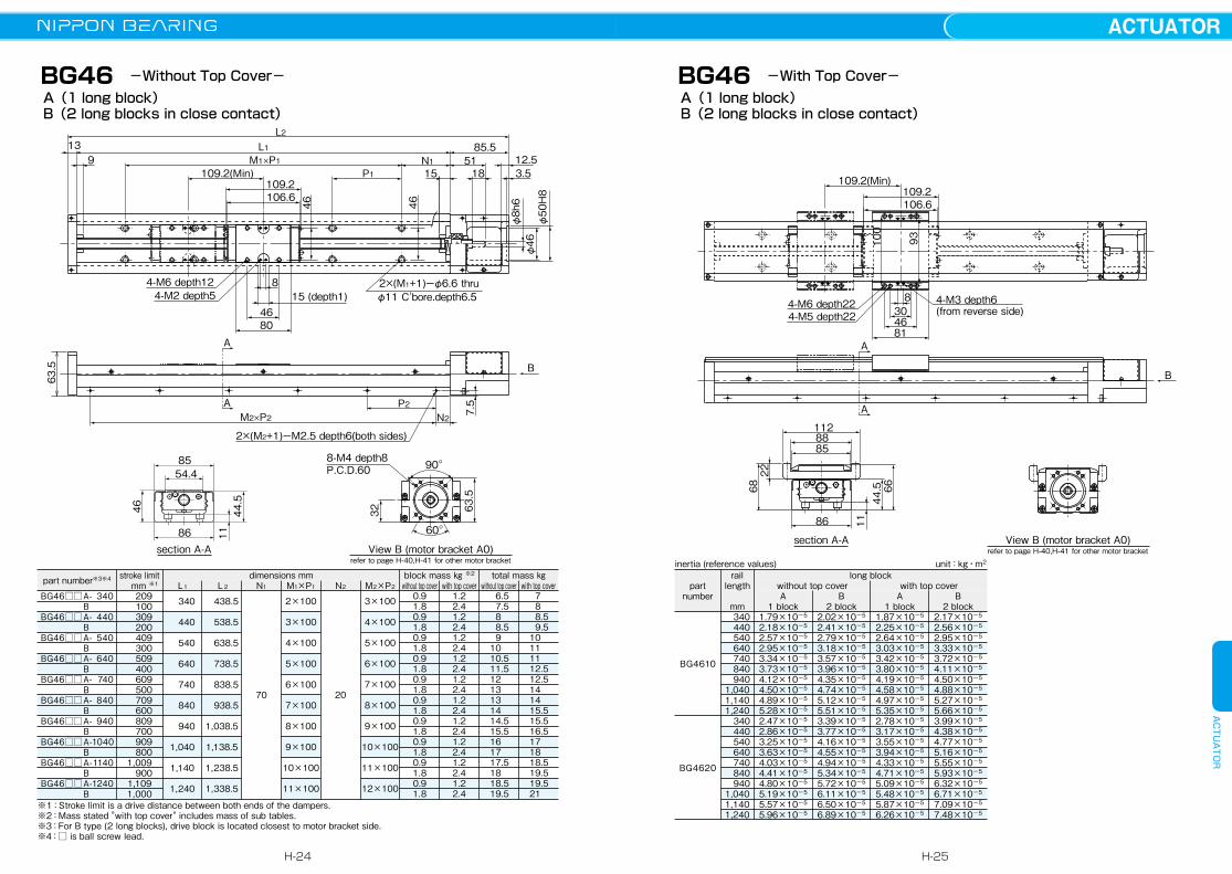
BG46 -Without Top Cover-
A
A
B
8-M4 depth8
32 63.5
P.C.D.60
section A-A View B (motor bracket A0)refer to page H-40,H-41 for other motor bracket
L2L113
9 M1×P1
M2×P2P2
N2
N1 51 12.53.51815P1109.2(Min)
109.2106.6
85.5
4-M6 depth124-M2 depth5
8
4680
15 (depth1)2×(M1+1)ーφ6.6 thru φ11 C'bore.depth6.5
2×(M2+1)ーM2.5 depth6(both sides)
90 。
7.5
4646
60 。
φ50H8
φ46
φ8h6
8554.4
86
46 44.5
11
63.5
A(1 long block)B(2 long blocks in close contact)
1128885
86
68
1144.5 66
22
A
A
B
section A-A View B (motor bracket A0)refer to page H-40,H-41 for other motor bracket
109.2106.6
109.2(Min)
81
83046
4-M6 depth224-M5 depth22
4-M3 depth6 (from reverse side)
100
93
A(1 long block)B(2 long blocks in close contact)
-With Top Cover-BG46
part number※3※4 stroke limit mm ※1 L1
dimensions mm block mass ㎏ ※2 total mass ㎏L2 N1 M1×P1 N2 M2×P2 without top cover with top cover without top cover with top cover
BG46□□ A- 340 BBG46□□ A- 440 BBG46□□ A- 540 BBG46□□ A- 640 BBG46□□ A- 740 BBG46□□ A- 840 BBG46□□ A- 940 BBG46□□ A- 1040 BBG46□□ A- 1140 BBG46□□ A- 1240 B
209 100 309 200 409 300 509 400 609 500 709 600 809 700 909 8001,009 9001,1091,000
340
440
540
640
740
840
940
1,040
1,140
1,240
438.5
538.5
638.5
738.5
838.5
938.5
1,038.5
1,138.5
1,238.5
1,338.5
70
2×100
3×100
4×100
5×100
6×100
7×100
8×100
9×100
10×100
11×100
20
3×100
4×100
5×100
6×100
7×100
8×100
9×100
10×100
11×100
12×100
0.91.80.91.80.91.80.91.80.91.80.91.80.91.80.91.80.91.80.91.8
1.22.41.22.41.22.41.22.41.22.41.22.41.22.41.22.41.22.41.22.4
6.5 7.5 8 8.5 9 10 10.5 11.5 12 13 13 14 14.5 15.5 16 17 17.5 18 18.5 19.5
7 8 8.5 9.5 10 11 11 12.5 12.5 14 14 15.5 15.5 16.5 17 18 18.5 19.5 19.5 21
※1:Stroke limit is a drive distance between both ends of the dampers.※2:Mass stated "with top cover" includes mass of sub tables.※3:For B type (2 long blocks), drive block is located closest to motor bracket side. ※4:□ is ball screw lead.
part number
rail length
mmA
1 blockA
1 blockB
2 blockB
2 block
without top cover with top coverlong block
BG4610
BG4620
340 440 540 640 740 840 9401,0401,1401,240 340 440 540 640 740 840 9401,0401,1401,240
1.79×10⁻⁵
2.18×10⁻⁵
2.57×10⁻⁵
2.95×10⁻⁵
3.34×10⁻⁵
3.73×10⁻⁵
4.12×10⁻⁵
4.50×10⁻⁵
4.89×10⁻⁵
5.28×10⁻⁵
2.47×10⁻⁵
2.86×10⁻⁵
3.25×10⁻⁵
3.63×10⁻⁵
4.03×10⁻⁵
4.41×10⁻⁵
4.80×10⁻⁵
5.19×10⁻⁵
5.57×10⁻⁵
5.96×10⁻⁵
1.87×10⁻⁵
2.25×10⁻⁵
2.64×10⁻⁵
3.03×10⁻⁵
3.42×10⁻⁵
3.80×10⁻⁵
4.19×10⁻⁵
4.58×10⁻⁵
4.97×10⁻⁵
5.35×10⁻⁵
2.78×10⁻⁵
3.17×10⁻⁵
3.55×10⁻⁵
3.94×10⁻⁵
4.33×10⁻⁵
4.71×10⁻⁵
5.09×10⁻⁵
5.48×10⁻⁵
5.87×10⁻⁵
6.26×10⁻⁵
2.02×10⁻⁵
2.41×10⁻⁵
2.79×10⁻⁵
3.18×10⁻⁵
3.57×10⁻⁵
3.96×10⁻⁵
4.35×10⁻⁵
4.74×10⁻⁵
5.12×10⁻⁵
5.51×10⁻⁵
3.39×10⁻⁵
3.77×10⁻⁵
4.16×10⁻⁵
4.55×10⁻⁵
4.94×10⁻⁵
5.34×10⁻⁵
5.72×10⁻⁵
6.11×10⁻⁵
6.50×10⁻⁵
6.89×10⁻⁵
2.17×10⁻⁵
2.56×10⁻⁵
2.95×10⁻⁵
3.33×10⁻⁵
3.72×10⁻⁵
4.11×10⁻⁵
4.50×10⁻⁵
4.88×10⁻⁵
5.27×10⁻⁵
5.66×10⁻⁵
3.99×10⁻⁵
4.38×10⁻⁵
4.77×10⁻⁵
5.16×10⁻⁵
5.55×10⁻⁵
5.93×10⁻⁵
6.32×10⁻⁵
6.71×10⁻⁵
7.09×10⁻⁵
7.48×10⁻⁵
inertia (reference values) unit:kg・m2
H-24
ACTUATORACTUATOR
H-25
BG46
A
A
B
8-M4 depth8
32 63.5
P.C.D.60
section A-A View B (motor bracket A0)refer to page H-40,H-41 for other motor bracket
L2L113
9 M1×P1
M2×P2P2
N2
N1 51 12.53.51815P1
85.5
2×(M1+1)ーφ6.6 thru φ11 C'bore.depth6.5
2×(M2+1)ーM2.5 depth6(both sides)
90 。
7.5
4646
60 。
φ50H8
φ46
φ8h6
8554.4
86
46 44.5
11
73.2(Min)73.270.6
8
44
46
3.515 (depth1)2-M6 depth12 4-M2 depth5
〃 〃
63.5
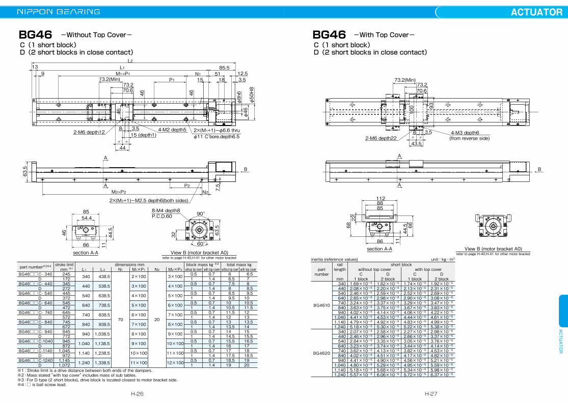
C(1 short block)D(2 short blocks in close contact)
-Without Top Cover-
1128885
86
68
1144.5 66
22
A
A
B
section A-A View B (motor bracket A0)refer to page H-40,H-41 for other motor bracket
73.270.6
8
43.5
100 93
3.52-M6 depth22
4-M3 depth6 (from reverse side)〃 〃
73.2(Min)
C(1 short block)D(2 short blocks in close contact)
-With Top Cover-BG46
part number※3※4 stroke limit mm ※1 L1
dimensions mm block mass ㎏ ※2 total mass ㎏L2 N1 M1×P1 N2 M2×P2 without top cover with top cover without top cover with top cover
BG46□□ C- 340 DBG46□□ C- 440 DBG46□□ C- 540 DBG46□□ C- 640 DBG46□□ C- 740 DBG46□□ C- 840 DBG46□□ C- 940 DBG46□□ C- 1040 DBG46□□ C- 1140 DBG46□□ C- 1240 D
245 172 345 272 445 372 545 472 645 572 745 672 845 772 945 8721,045 9721,1451,072
340
440
540
640
740
840
940
1.040
1.140
1.240
438.5
538.5
638.5
738.5
838.5
938.5
1,038.5
1,138.5
1,238.5
1,338.5
70
2×100
3×100
4×100
5×100
6×100
7×100
8×100
9×100
10×100
11×100
20
3×100
4×100
5×100
6×100
7×100
8×100
9×100
10×100
11×100
12×100
0.5 1 0.5 1 0.5 1 0.5 1 0.5 1 0.5 1 0.5 1 0.5 1 0.5 1 0.5 1
0.71.40.71.40.71.40.71.40.71.40.71.40.71.40.71.40.71.40.71.4
6 6.5 7.5 8 8.5 9.5 10 10.5 11.5 12 13 13.5 14 14.5 15.5 16 17 17.5 18.5 19
6.5 7 8 8.5 9.5 10 10.5 11.5 12 13 13.5 14 15 15.5 16.5 17 18 18.5 19 20
※1:Stroke limit is a drive distance between both ends of the dampers.※2:Mass stated "with top cover" includes mass of sub tables.※3:For D type (2 short blocks), drive block is located closest to motor bracket side. ※4:□ is ball screw lead.
part number
rail length
mmC
1 blockC
1 blockD
2 blockD
2 block
without top cover with top covershort block
BG4610
BG4620
340 440 540 640 740 840 9401,0401,1401,240 340 440 540 640 740 840 9401,0401,1401,240
1.69×10⁻⁵
2.08×10⁻⁵
2.46×10⁻⁵
2.85×10⁻⁵
3.24×10⁻⁵
3.63×10⁻⁵
4.02×10⁻⁵
4.41×10⁻⁵
4.79×10⁻⁵
5.18×10⁻⁵
2.07×10⁻⁵
2.46×10⁻⁵
2.84×10⁻⁵
3.23×10⁻⁵
3.62×10⁻⁵
4.02×10⁻⁵
4.41×10⁻⁵
4.80×10⁻⁵
5.18×10⁻⁵
5.57×10⁻⁵
1.74×10⁻⁵
2.13×10⁻⁵
2.52×10⁻⁵
2.90×10⁻⁵
3.29×10⁻⁵
3.67×10⁻⁵
4.06×10⁻⁵
4.44×10⁻⁵
4.83×10⁻⁵
5.22×10⁻⁵
2.27×10⁻⁵
2.66×10⁻⁵
3.05×10⁻⁵
3.44×10⁻⁵
3.82×10⁻⁵
4.17×10⁻⁵
4.56×10⁻⁵
4.95×10⁻⁵
5.34×10⁻⁵
5.72×10⁻⁵
1.82×10⁻⁵
2.20×10⁻⁵
2.59×10⁻⁵
2.98×10⁻⁵
3.37×10⁻⁵
3.75×10⁻⁵
4.14×10⁻⁵
4.53×10⁻⁵
4.92×10⁻⁵
5.30×10⁻⁵
2.58×10⁻⁵
2.96×10⁻⁵
3.35×10⁻⁵
3.74×10⁻⁵
4.13×10⁻⁵
4.51×10⁻⁵
4.90×10⁻⁵
5.29×10⁻⁵
5.68×10⁻⁵
6.06×10⁻⁵
1.92×10⁻⁵
2.31×10⁻⁵
2.69×10⁻⁵
3.08×10⁻⁵
3.47×10⁻⁵
3.83×10⁻⁵
4.22×10⁻⁵
4.61×10⁻⁵
4.99×10⁻⁵
5.38×10⁻⁵
2.98×10⁻⁵
3.37×10⁻⁵
3.76×10⁻⁵
4.14×10⁻⁵
4.53×10⁻⁵
4.82×10⁻⁵
5.21×10⁻⁵
5.59×10⁻⁵
5.98×10⁻⁵
6.37×10⁻⁵
inertia (reference values) unit:kg・m2
H-26
ACTUATORACTUATOR
H-27
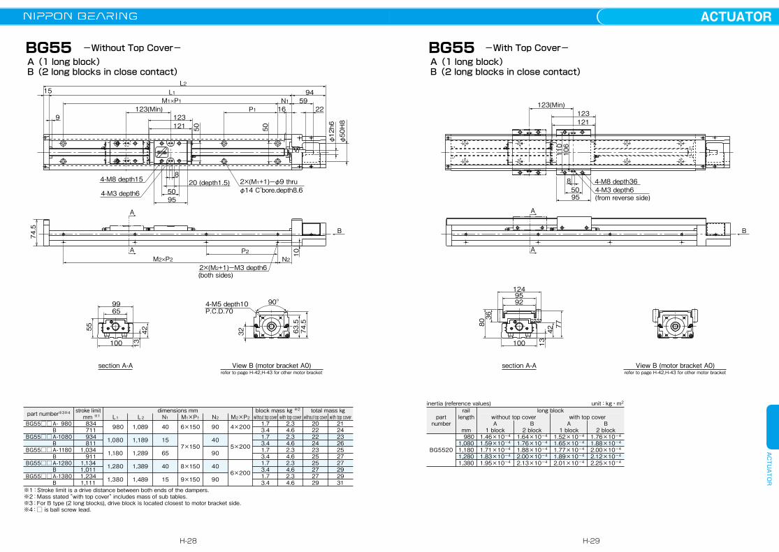
BG55
section A-A View B (motor bracket A0)refer to page H-42,H-43 for other motor bracket
B
A
A
74.5
L2L115
M1×P1
M2×P2P2
N2
N1 592216P1123(Min)
1239121
94
4-M8 depth15
4-M5 depth10P.C.D.70
32 74.5
63.5
4-M3 depth6
8
5095
20 (depth1.5) 2×(M1+1)ーφ9 thru
2×(M2+1)ーM3 depth6(both sides)
φ14 C'bore.depth8.6
90 。
10
φ12h6
φ50H8
5050
9965
100
55 4213
A(1 long block)B(2 long blocks in close contact)
-Without Top Cover-
section A-A View B (motor bracket A0)refer to page H-42,H-43 for other motor bracket
123(Min)
95
850
4-M8 depth364-M3 depth6(from reverse side)
110
106
123121
B
A
A
8036
7742
13
1249592
100
A(1 long block)B(2 long blocks in close contact)
-With Top Cover-BG55
part number※3※4 stroke limit mm ※1 L1
dimensions mm block mass ㎏ ※2 total mass ㎏L2 N1 M1×P1 N2 M2×P2 without top cover with top cover without top cover with top cover
BG55□□ A- 980 BBG55□□ A- 1080 BBG55□□ A- 1180 BBG55□□ A- 1280 BBG55□□ A- 1380 B
834 711 934 8111,034 9111,1341,0111,2341,111
980
1,080
1,180
1,280
1,380
1,089
1,189
1,289
1,389
1,489
40
15
65
40
15
6×150
7×150
8×150
9×150
90
40
90
40
90
4×200
5×200
6×200
1.73.41.73.41.73.41.73.41.73.4
2.34.62.34.62.34.62.34.62.34.6
20222224232525272729
21242326252727292931
※1:Stroke limit is a drive distance between both ends of the dampers.※2:Mass stated "with top cover" includes mass of sub tables.※3:For B type (2 long blocks), drive block is located closest to motor bracket side. ※4:□ is ball screw lead.
part number
rail length
mmA
1 blockA
1 blockB
2 blockB
2 block
without top cover with top coverlong block
BG5520
9801,0801,1801,2801,380
1.46×10⁻⁴
1.59×10⁻⁴
1.71×10⁻⁴
1.83×10⁻⁴
1.95×10⁻⁴
1.52×10⁻⁴
1.65×10⁻⁴
1.77×10⁻⁴
1.89×10⁻⁴
2.01×10⁻⁴
1.64×10⁻⁴
1.76×10⁻⁴
1.88×10⁻⁴
2.00×10⁻⁴
2.13×10⁻⁴
1.76×10⁻⁴
1.88×10⁻⁴
2.00×10⁻⁴
2.12×10⁻⁴
2.25×10⁻⁴
inertia (reference values) unit:kg・m2
H-28
ACTUATORACTUATOR
H-29
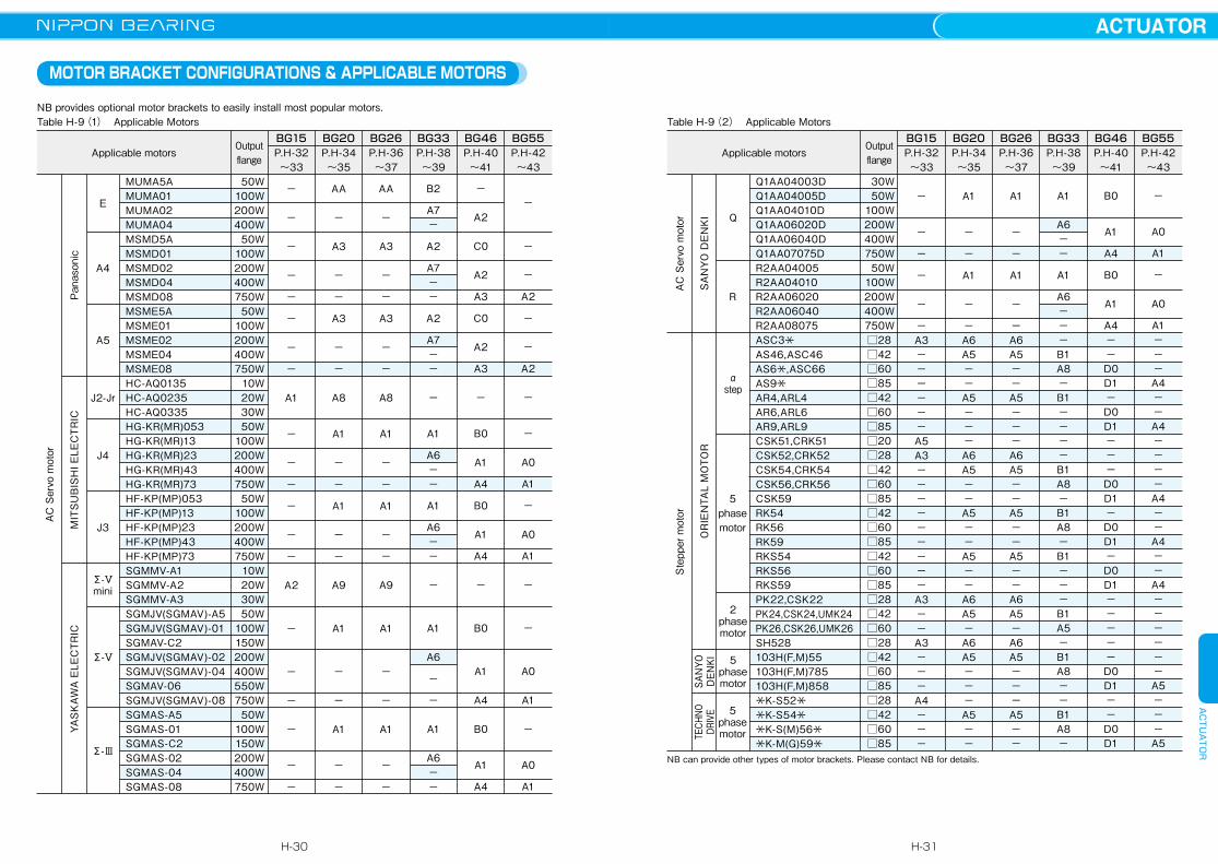
MOTOR BRACKET CONFIGURATIONS & APPLICABLE MOTORS
NB provides optional motor brackets to easily install most popular motors.Table H-9(1) Applicable Motors Table H-9(2) Applicable Motors
AC
Ser
vo m
otor
AC
Ser
vo m
otor
Ste
pper
mot
or
Pan
ason
ic
SA
NYO
DE
NK
I
MIT
SU
BIS
HI E
LEC
TRIC
OR
IEN
TAL
MO
TOR
SAN
YO
DEN
KI
YAS
KAW
A E
LEC
TRIC
TECH
NO
DRIV
E
EQ
A4
A5
R
J2-Jr
αstep
J4
5 phase motorJ3
∑-Ⅴmini
∑-Ⅴ
2 phase motor
5 phase motor
∑-Ⅲ
5 phase motor
MUMA5AMUMA01MUMA02MUMA04MSMD5AMSMD01MSMD02MSMD04MSMD08MSME5AMSME01MSME02MSME04MSME08HC-AQ0135HC-AQ0235HC-AQ0335HG-KR(MR)053HG-KR(MR)13HG-KR(MR)23HG-KR(MR)43HG-KR(MR)73HF-KP(MP)053HF-KP(MP)13HF-KP(MP)23HF-KP(MP)43HF-KP(MP)73SGMMV-A1SGMMV-A2SGMMV-A3SGMJV(SGMAV)-A5SGMJV(SGMAV)-01SGMAV-C2SGMJV(SGMAV)-02SGMJV(SGMAV)-04SGMAV-06SGMJV(SGMAV)-08SGMAS-A5SGMAS-01SGMAS-C2SGMAS-02SGMAS-04SGMAS-08
Q1AA04003DQ1AA04005DQ1AA04010DQ1AA06020DQ1AA06040DQ1AA07075DR2AA04005R2AA04010R2AA06020R2AA06040R2AA08075ASC3*AS46,ASC46AS6*,ASC66AS9*AR4,ARL4AR6,ARL6AR9,ARL9CSK51,CRK51CSK52,CRK52CSK54,CRK54CSK56,CRK56CSK59RK54RK56RK59RKS54RKS56RKS59PK22,CSK22PK24,CSK24,UMK24PK26,CSK26,UMK26SH528103H(F,M)55103H(F,M)785103H(F,M)858
*K-S52* *K-S54**K-S(M)56**K-M(G)59*
50W100W200W400W
50W100W200W400W750W50W
100W200W400W750W
10W20W30W50W
100W200W400W750W50W
100W200W400W750W
10W20W30W50W
100W150W200W400W550W750W50W
100W150W200W400W750W
30W50W
100W200W400W750W50W
100W200W400W750W□28□42□60□85□42□60□85□20□28□42□60□85□42□60□85□42□60□85□28□42□60□28□42□60□85□28□42□60□85
Applicable motors Applicable motorsOutput flange
Output flange
P.H-32〜33
P.H-32〜33
P.H-34〜35
P.H-34〜35
P.H-36〜37
P.H-36〜37
P.H-38〜39
P.H-38〜39
P.H-40〜41
P.H-40〜41
P.H-42〜43
P.H-42〜43
BG20 BG20BG15 BG15BG26 BG26BG33 BG33BG46 BG46BG55 BG55
NB can provide other types of motor brackets. Please contact NB for details.
−
−
−
−
−
−
−
−
A1
−
−
−
−
−
−
A2
−
−
−
−
−
−
−
−
−
−
−
−A3−−−−−−A5A3−−−−−−−−−A3−−A3−−−A4−−−
AA
−
A3
−
−
A3
−
−
A8
A1
−
−
A1
−
−
A9
A1
−
−
A1
−
−
A1
−
−
A1
−
−A6A5−−A5−−−A6A5−−A5−−A5−−A6A5−A6A5−−−A5−−
AA
−
A3
−
−
A3
−
−
A8
A1
−
−
A1
−
−
A9
A1
−
−
A1
−
−
A1
−
−
A1
−
−A6A5−−A5−−−A6A5−−A5−−A5−−A6A5−A6A5−−−A5−−
B2
A7−
A2
A7−−
A2
A7−−
−
A1
A6−−
A1
A6−−
−
A1
A6
−
−
A1
A6−−
A1
A6−−
A1
A6−−−B1A8−B1−−−−B1A8−B1A8−B1−−−B1A5−B1A8−−B1A8−
−
A2
C0
A2
A3
C0
A2
A3
−
B0
A1
A4
B0
A1
A4
−
B0
A1
A4
B0
A1
A4
B0
A1
A4
B0
A1
A4−−D0D1−D0D1−−−D0D1−D0D1−D0D1−−−−−D0D1−−D0D1
−
−
−
A2
−
−
A2
−
−
A0
A1
−
A0
A1
−
−
A0
A1
−
A0
A1
−
A0
A1
−
A0
A1−−−A4−−A4−−−−A4−−A4−−A4−−−−−−A5−−−A5
H-30
ACTUATORACTUATOR
H-31

BG15Figures inside( ) indicates mass of the motor mount adapter plate.
25
29.5
10
724.5
42
φ17
2
5.5
822
4-φ2.4 thru
9.5
φ3h6
φ20+0.05
0
29.590°
42 6
1.5
φ17
3.5
4-M2.5 depth6 P.C.D33
28
φ20+0.05
0
90°
29.54-φ3.5 thruφ6.5 C'bore.depth3.5(opposite side)P.C.D28
3.5
1.5
φ17
642
26
φ20+0.05
0
23
29.542 6
φ17
1.5
2.5
4-φ3 thruφ5 C'bore.depth3(opposite side)
23 28
φ22+0.05
0
A0
A1 (Mass: 9g)Recommended Coupling: XBW-15C2(Nabeya Bi-tech Kaisha)
SFC-005DA2(Miki Pully Co., Ltd.)
A2 (Mass: 8g)Recommended Coupling: LAD-15C(Sakai Manufacturing Co., Ltd.)
XBW-15C2(Nabeya Bi-tech Kaisha)SFC-005DA2(Miki Pully Co., Ltd.)
A3 (Mass: 9g)Recommended Coupling: LAD-15C(Sakai Manufacturing Co., Ltd.)
XBW-15C2(Nabeya Bi-tech Kaisha)SFC-005DA2(Miki Pully Co., Ltd.)
19
29.5 4-φ3 thruφ5 C'bore.depth3(opposite side)
42 6
φ17
1.5
2
19 24
φ18+0.05
0
1.5
4229.516
34-φ2.4 thruφ4.2 C'bore.depth2.2(opposite side)
16 22
φ16+0.05
0
42 3
1.5 29.516
16 22
4-φ2.4 thruφ4.2 C'bore.depth2.2(opposite side)
φ15+0.05
0
42
1.590°
29.5
24
4-φ3 thruφ5 C'bore.depth3(opposite side)P.C.D13.6
6
φ11+0.05
0
A5 (Mass: 4g)Recommended Coupling: XBW-15C2(Nabeya Bi-tech Kaisha)
A6 (Mass: 4g)Recommended Coupling: XBW-15C2(Nabeya Bi-tech Kaisha)
A4 (Mass: 8g)Recommended Coupling: LAD-15C(Sakai Manufacturing Co., Ltd.)
XBW-15C2(Nabeya Bi-tech Kaisha)SFC-005DA2(Miki Pully Co., Ltd.)
A7 (Mass: 11g)Recommended Coupling: LAD-15C(Sakai Manufacturing Co., Ltd.)
XBW-15C2(Nabeya Bi-tech Kaisha)
Attach the motor to the motor mount adapter plate first.
H-32
ACTUATORACTUATOR
H-33
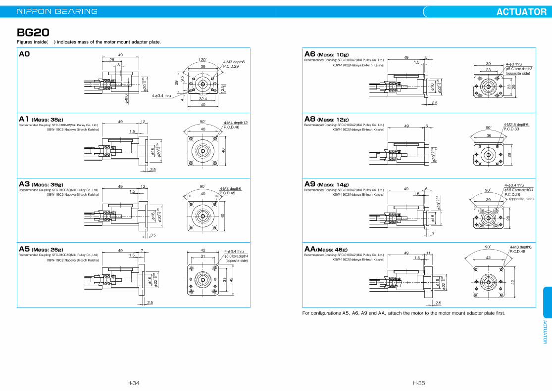
BG20Figures inside( ) indicates mass of the motor mount adapter plate.
4926
8
φ4h6
φ20+0.05
0
P.C.D.294-M3 depth6
4
4-φ3.4 thru
4032.4
299.5
12.5
39
120゚
49 12
1.5
3.5
φ30+0.05
0
φ16 40
P.C.D.464-M4 depth1290゚
40
49 121.5
3.5
φ30+0.05
0
φ16 40
P.C.D.454-M3 depth690゚
40
49 71.5
2.5
φ22+0.05
0
φ16 31 42
4-φ3.4 thru4231
(opposite side)φ6 C'bore.depth4
A0
A1 (Mass: 38g)Recommended Coupling: SFC-010DA2(Miki Pulley Co., Ltd.) XBW-19C2(Nabeya Bi-tech Kaisha)
A3 (Mass: 39g)Recommended Coupling: SFC-010DA2(Miki Pulley Co., Ltd.) XBW-19C2(Nabeya Bi-tech Kaisha)
A5 (Mass: 26g)Recommended Coupling: SFC-010DA2(Miki Pulley Co., Ltd.) XBW-19C2(Nabeya Bi-tech Kaisha)
49 6
φ20+0.05
0
P.C.D.334-M2.5 depth6
90゚
39
49 61.5
3
φ20+0.05
0
φ16 28
28
P.C.D.2890゚
39
4-φ3.4 thru
(opposite side)
φ6.5 C'bore.depth3.4
49 111.5
2.5
φ22+0.05
0
φ16 42
P.C.D.484-M3 depth690゚
42
A9 (Mass: 14g)Recommended Coupling: SFC-010DA2(Miki Pulley Co., Ltd.) XBW-19C2(Nabeya Bi-tech Kaisha)
AA(Mass: 46g)Recommended Coupling: SFC-010DA2(Miki Pulley Co., Ltd.) XBW-19C2(Nabeya Bi-tech Kaisha)
A8 (Mass: 12g)Recommended Coupling: SFC-010DA2(Miki Pulley Co., Ltd.) XBW-19C2(Nabeya Bi-tech Kaisha)
49 51.5
2.5
φ22+0.05
0
φ16 23 29
39
234-φ3 thru
(opposite side)φ5 C'bore.depth3
A6 (Mass: 10g)Recommended Coupling: SFC-010DA2(Miki Pulley Co., Ltd.) XBW-19C2(Nabeya Bi-tech Kaisha)
For configurations A5,A6, A9 and AA,attach the motor to the motor mount adapter plate first.
H-34
ACTUATORACTUATOR
H-35

BG26Figures inside( ) indicates mass of the motor mount adapter plate.
5230.5
10
φ24+0.05
0
φ5h6
P.C.D.334-M3 depth6
90゚49
4250
16
3713.5
3.8
4-φ3.4 thru
52
2
10.5
3.5
90゚
40
40
φ30+0.05
0
φ22
52210.5
3.5
P.C.D.454-M3 depth10.5
P.C.D.464-M4 depth10.5
90゚
38
38
φ30+0.05
0
φ22
522
2.5
7 4931
31 42
φ22+0.05
0
φ16
4-φ3.4 thru
(opposite side) φ6 C'bore.depth4
A1 (Mass: 28g)Recommended Coupling: SFC-010DA2(Miki Pulley Co., Ltd.) LAD-20C(Sakai Manufacturing Co., Ltd.) XBW-19C2(Nabeya Bi-tech Kaisha)
A3 (Mass: 24g)Recommended Coupling: SFC-010DA2(Miki Pulley Co., Ltd.) LAD-20C(Sakai Manufacturing Co., Ltd.) XBW-19C2(Nabeya Bi-tech Kaisha)
A5 (Mass: 32g)Recommended Coupling: SFC-010DA2(Miki Pulley Co., Ltd.) LAD-20C(Sakai Manufacturing Co., Ltd.) XBW-19C2(Nabeya Bi-tech Kaisha)
A0
3
5226 P.C.D.33
4-M2.5 depth690゚
49
φ20+0.05
0
φ16
30.4
3
5226
90゚
49
φ20+0.05
0
φ16
30.4
P.C.D.28
4-φ3.4 thru
(opposite side)
φ6.5 C'bore.depth3.4
522
11 P.C.D.484-M3 depth690゚
42
42
φ22+0.05
0
522
2.5
5
φ22+0.05
0
φ16
4923
23 30.4
4-φ3 thru
(opposite side)φ5 C'bore.depth3
A8 (Mass: 21g)Recommended Coupling: SFC-010DA2(Miki Pulley Co., Ltd.) LAD-20C(Sakai Manufacturing Co., Ltd.) XBW-19C2(Nabeya Bi-tech Kaisha)
A9 (Mass: 21g)Recommended Coupling: SFC-010DA2(Miki Pulley Co., Ltd.) LAD-20C(Sakai Manufacturing Co., Ltd.) XBW-19C2(Nabeya Bi-tech Kaisha)
AA (Mass: 41g)Recommended Coupling: SFC-010DA2(Miki Pulley Co., Ltd.) LAD-20C(Sakai Manufacturing Co., Ltd.) XBW-19C2(Nabeya Bi-tech Kaisha)
A6 (Mass: 16g)Recommended Coupling: SFC-010DA2(Miki Pulley Co., Ltd.) LAD-20C(Sakai Manufacturing Co., Ltd.) XBW-19C2(Nabeya Bi-tech Kaisha)
For configurations A5,A6 and A9,attach the motor to the motor mount adapter plate first.
H-36
ACTUATORACTUATOR
H-37
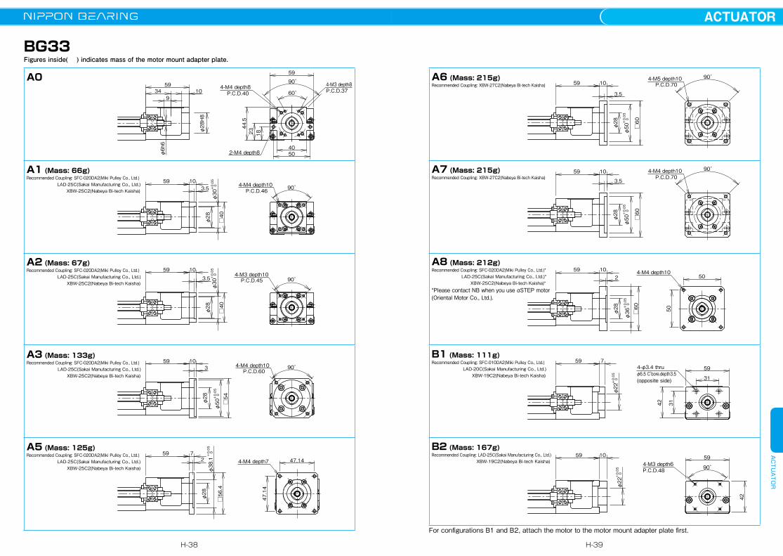
BG33Figures inside( ) indicates mass of the motor mount adapter plate.
5934 10
9
φ28H8
44.5
23 18
φ6h6
P.C.D.40
P.C.D.46
P.C.D.45
P.C.D.60
4-M4 depth8P.C.D.374-M3 depth8
60゚
90゚
59
4050
59 103.5
4-M4 depth10 90゚
φ30+0.05
0
φ28
□40
59 10
3.54-M3 depth10
90゚
φ30+0.05
0
φ28
□40
4-M4 depth10 90゚
2-M4 depth8
59 103
φ50+0.05
0
φ28
□54
59 72
47.14
4-M4 depth7 47.14
φ38.1+0.05
0
φ28
□56.4
A0
A1 (Mass: 66g)Recommended Coupling: SFC-020DA2(Miki Pulley Co., Ltd.) LAD-25C(Sakai Manufacturing Co., Ltd.) XBW-25C2(Nabeya Bi-tech Kaisha)
A2 (Mass: 67g)Recommended Coupling: SFC-020DA2(Miki Pulley Co., Ltd.) LAD-25C(Sakai Manufacturing Co., Ltd.) XBW-25C2(Nabeya Bi-tech Kaisha)
A3 (Mass: 133g)Recommended Coupling: SFC-020DA2(Miki Pulley Co., Ltd.) LAD-25C(Sakai Manufacturing Co., Ltd.) XBW-25C2(Nabeya Bi-tech Kaisha)
A5 (Mass: 125g)Recommended Coupling: SFC-020DA2(Miki Pulley Co., Ltd.) LAD-25C(Sakai Manufacturing Co., Ltd.) XBW-25C2(Nabeya Bi-tech Kaisha)
P.C.D.70
P.C.D.70
59 10
3.5
4-M5 depth10 90゚
φ50+0.05
0
φ28
□60
59 10
3.5
4-M4 depth10 90゚
φ50+0.05
0
φ28
□60
5959
31
7
φ22+0.05
0
42 31
4-φ3.4 thru
(opposite side)φ6.5 C'bore.depth3.5
5959 10
90゚
φ22+0.05
0
42
P.C.D.484-M3 depth6
5950
102
4-M4 depth10
φ36+0.05
0
φ28
□60 50
A6 (Mass: 215g) Recommended Coupling: XBW-27C2(Nabeya Bi-tech Kaisha)
A7 (Mass: 215g)Recommended Coupling: XBW-27C2(Nabeya Bi-tech Kaisha)
B1 (Mass: 111g) Recommended Coupling: SFC-010DA2(Miki Pulley Co., Ltd.) LAD-20C(Sakai Manufacturing Co., Ltd.) XBW-19C2(Nabeya Bi-tech Kaisha)
B2 (Mass: 167g) Recommended Coupling: LAD-25C(Sakai Manufacturing Co., Ltd.) XBW-19C2(Nabeya Bi-tech Kaisha)
A8 (Mass: 212g)Recommended Coupling: SFC-020DA2(Miki Pulley Co., Ltd.)* LAD-25C(Sakai Manufacturing Co., Ltd.)* XBW-25C2(Nabeya Bi-tech Kaisha)**Please contact NB when you use αSTEP motor (Oriental Motor Co., Ltd.).
For configurations B1 and B2, attach the motor to the motor mount adapter plate first.
H-38
ACTUATORACTUATOR
H-39
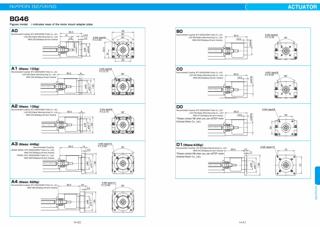
BG46Figures inside( ) indicates mass of the motor mount adapter plate.
8-M4 depth8P.C.D.60
P.C.D.70
P.C.D.70
P.C.D.90
P.C.D.90
63.5
32
85
63
60°90°
85.512.53.518
51
φ46
φ8h6
φ50H8
φ46
4-M5 depth8
□62
90°885.5
φ50
+0.05
0
φ46
4-M4 depth8
□62
90°85.5 8
φ50
+0.05
0
φ46
4-M5 depth1090°
□80
85.5 153.5
φ70
+0.05
0
4-M6 depth12
φ46
□80
3.52085.5 90°
φ70
+0.05
0
A0Recommended Coupling: SFC-020DA2(Miki Pulley Co., Ltd.) LAD-25C(Sakai Manufacturing Co., Ltd.) XBW-25C2(Nabeya Bi-tech Kaisha)
A1 (Mass: 103g)Recommended Coupling: SFC-030DA2(Miki Pulley Co., Ltd.) LAD-30C(Sakai Manufacturing Co., Ltd.) XBW-34C3(Nabeya Bi-tech Kaisha)
A2 (Mass: 106g)Recommended Coupling: SFC-030DA2(Miki Pulley Co., Ltd.) LAD-30C(Sakai Manufacturing Co., Ltd.) XBW-34C3(Nabeya Bi-tech Kaisha)
A3 (Mass: 448g) Recommended Coupling(200W-400W): SFC-030DA2(Miki Pulley Co., Ltd.) XBW-34C3(Nabeya Bi-tech Kaisha) (750W): SFC-040DA2(Miki Pulley Co., Ltd.) XBW-39C2(Nabeya Bi-tech Kaisha)
A4 (Mass: 628g)Recommended Coupling: SFC-040DA2(Miki Pulley Co., Ltd.) XBW-39C2(Nabeya Bi-tech Kaisha)
4-M4 depth8P.C.D.46
P.C.D.45
90°85.512.5
φ30H8
4-M3 depth890°
85.512.5
φ30H8
4-M4 depth8
50
5085.512.5
φ36H8
85.5 10
φ36
□85
70
70
4-M5 depth10
3
φ60
+0.05
0
B0Recommended Coupling: SFC-020DA2(Miki Pulley Co., Ltd.) LAD-25C(Sakai Manufacturing Co., Ltd.) XBW-25C2(Nabeya Bi-tech Kaisha)
C0 Recommended Coupling: SFC-020DA2(Miki Pulley Co., Ltd.) LAD-25C(Sakai Manufacturing Co., Ltd.) XBW-25C2(Nabeya Bi-tech Kaisha)
D0Recommended Coupling: SFC-020DA2(Miki Pulley Co., Ltd.)* LAD-25C(Sakai Manufacturing Co., Ltd.)* XBW-27C2(Nabeya Bi-tech Kaisha)*Please contact NB when you use αSTEP motor (Oriental Motor Co., Ltd.).
D1(Mass:435g)Recommended Coupling: LAD-35C(Sakai Manufacturing Co., Ltd.)* XBW-34C3(Nabeya Bi-tech Kaisha)**Please contact NB when you use αSTEP motor (Oriental Motor Co., Ltd.).
H-40
ACTUATORACTUATOR
H-41
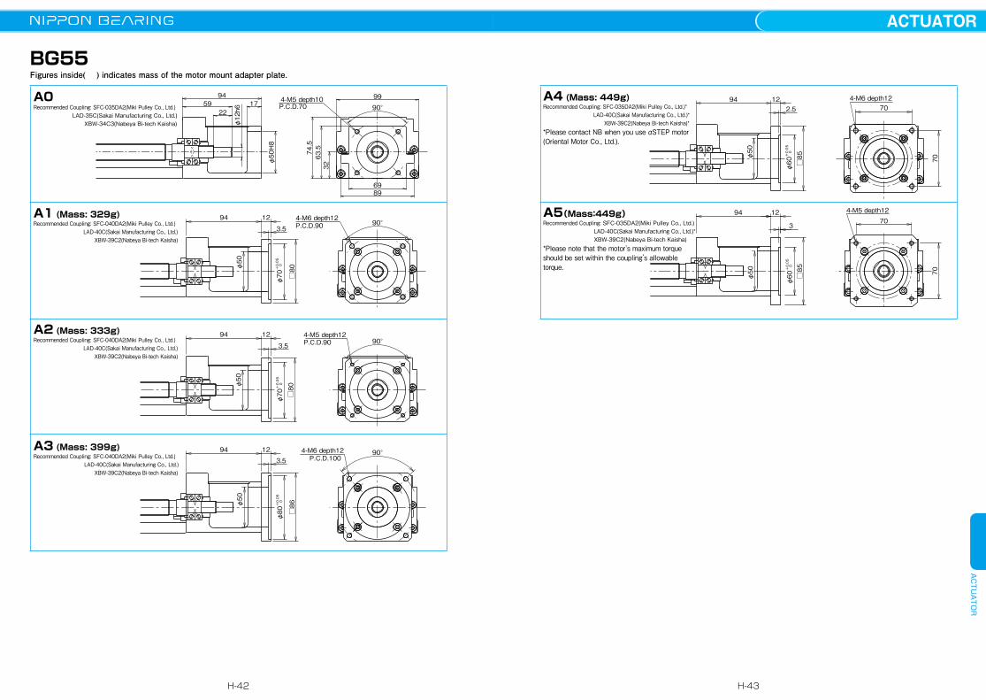
BG55Figures inside( ) indicates mass of the motor mount adapter plate.
φ12h6
4-M5 depth10P.C.D.70
P.C.D.90
P.C.D.90
P.C.D.100
φ50H8
63.574.5
32
8969
99
90°
941759
22
4-M6 depth1290°
□80φ50
94 12
3.5
φ70
+0.05
0
4-M5 depth1290°
□80φ50
94 12
3.5
φ70
+0.05
0
4-M6 depth12 90°
□86φ50
94 12
3.5
φ80
+0.05
0
A0Recommended Coupling: SFC-035DA2(Miki Pulley Co., Ltd.) LAD-35C(Sakai Manufacturing Co., Ltd.) XBW-34C3(Nabeya Bi-tech Kaisha)
A1 (Mass: 329g)Recommended Coupling: SFC-040DA2(Miki Pulley Co., Ltd.) LAD-40C(Sakai Manufacturing Co., Ltd.) XBW-39C2(Nabeya Bi-tech Kaisha)
A2 (Mass: 333g)Recommended Coupling: SFC-040DA2(Miki Pulley Co., Ltd.) LAD-40C(Sakai Manufacturing Co., Ltd.) XBW-39C2(Nabeya Bi-tech Kaisha)
A3 (Mass: 399g)Recommended Coupling: SFC-040DA2(Miki Pulley Co., Ltd.) LAD-40C(Sakai Manufacturing Co., Ltd.) XBW-39C2(Nabeya Bi-tech Kaisha)
φ60
+0.05
0
1294
□85
70
70
3
4-M5 depth12
φ50
4-M6 depth12
70
70
□85φ50
94 122.5
φ60
+0.05
0
A5(Mass:449g)Recommended Coupling: SFC-035DA2(Miki Pulley Co., Ltd.) LAD-40C(Sakai Manufacturing Co., Ltd.)* XBW-39C2(Nabeya Bi-tech Kaisha)*Please note that the motor's maximum torque should be set within the coupling’s allowable torque.
A4 (Mass: 449g)Recommended Coupling: SFC-035DA2(Miki Pulley Co., Ltd.)* LAD-40C(Sakai Manufacturing Co., Ltd.)* XBW-39C2(Nabeya Bi-tech Kaisha)**Please contact NB when you use αSTEP motor (Oriental Motor Co., Ltd.).
H-42
ACTUATORACTUATOR
H-43
60
44.5
34 (helical inserts)4-M4 depth8
0.5
44
59
2327
4149 27
16
φ6h6
φ30h8
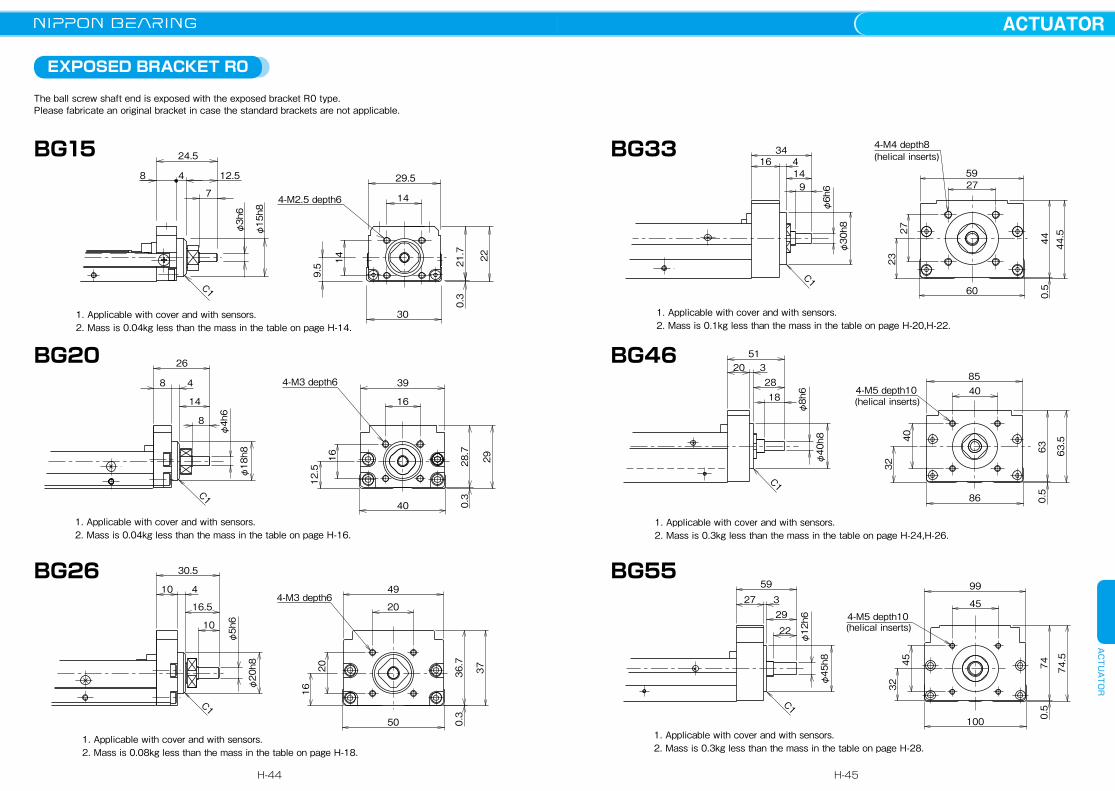
1. Applicable with cover and with sensors.2. Mass is 0.1kg less than the mass in the table on page H-20,H-22.
C1
86
20 32818
51
φ40h8
φ8h6
(helical inserts)4-M5 depth10
63.5
0.5
63
32
40
4085
1. Applicable with cover and with sensors.2. Mass is 0.3kg less than the mass in the table on page H-24,H-26.
C1
φ12h6
φ45h8
59
22
293
74
32
0.5
100
(helical inserts)4-M5 depth10
45
45
9927
74.5
1. Applicable with cover and with sensors.2. Mass is 0.3kg less than the mass in the table on page H-28.
C1C1
4-M3 depth649
0.3
50
37
16
4
φ20h8
φ5h6
20
16.5
10
20
30.5
36.7
10
1. Applicable with cover and with sensors.2. Mass is 0.08kg less than the mass in the table on page H-18.
BG33
BG26
BG46
BG55
EXPOSED BRACKET R0
The ball screw shaft end is exposed with the exposed bracket R0 type. Please fabricate an original bracket in case the standard brackets are not applicable.
1. Applicable with cover and with sensors.2. Mass is 0.04kg less than the mass in the table on page H-14.
24.5
22
8 12.54
7
φ3h6
21.7
30
14
29.5
0.3
φ15h8
4-M2.5 depth6
C1
14
9.5
C1
φ18h8
φ4h6
26
8
14
48
0.3
2928.7
12.5
40
39
16
16
4-M3 depth6
1. Applicable with cover and with sensors.2. Mass is 0.04kg less than the mass in the table on page H-16.
BG20
BG15
H-44
ACTUATORACTUATOR
H-45

RETURN PULLEY UNIT
Return pulley units in which a motor is connected with a timing belt are available for BG type. Its return structure allows the reduction of total length (available for BG33 and BG46).
1.This drawing shows RA for MSMA01(Panasonic).2.Installation position of Pulley Unit can be selected at 90° intervals (mounting direction code).3.Applicable with cover and with sensors. Precaution for applying H type sensors When the motor is positioned at direction 3 or 9, H type sensors interfere if mounted on the side of motor.
H type sensors must be mounted opposite to the motor.4.Tension plate can be built in and is not exposed. (not applicable to RC)5.Mass is added 0.2kg to the mass on page H-20〜23.6.Inertia is added 2.22×10⁻⁶kg・m2 to the value of Table on page H-20〜23. (motor inertia not included)7.Part number structure BG33***―****/ ☆☆□ ☆☆: Symbol of applicable motor bracket (refer to Table H-10) □: Mounting direction code (refer to cross section A-A)
A
A
cross section A-A
tension plate isnot exposed
mounting direction code 0
mounting direction code 6
mounting direction code 9
mounting direction code 3
916 28
42 244.5
60
16
□38
103
2472
21117
18
tension plate21
d
d=1.1mmTd=1.9N
tension
Td
Please contact NB for other stepper motors. Please contact NB for other stepper motors.
1.This drawing shows RA for MSMA01(Panasonic).2.Installation position of Pulley Unit can be selected at 90° intervals (mounting direction code).3.Applicable with cover and with sensors. Precaution for applying H type sensors When the motor is positioned at direction 3 or 9, H type sensors interfere if mounted on the side of motor.
H type sensors must be mounted opposite to the motor.4.Tension plate can be built in and is not exposed.5.Mass is added 0.7kg to the mass on page H-24 〜27. 6.Inertia is added 1.24×10⁻⁵kg・m2 to the value of Table on page H-24〜27. (motor inertia not included)7.Parts number structure BG46***―****/☆☆□ ☆☆: Symbol of applicable motor bracket (refer to Table H-11) □: Mounting direction code (refer to cross section A-A)
A
A
cross section A-A
tension plate isnot exposed
mounting directioncode 0
mounting directioncode 6
mounting directioncode 9
mounting directioncode 3
94
□60
1220 34 62 1
63.5
86
20
31102
34167
25
tension plate
31
d
d=1.6mmTd=2.9N
tension
Td
BG33 BG46
Return pulley units is available for sizes other than BG33 and BG46. Please contact NB.
Table H-10 Applicable Motor Table H-11 Applicable Motormotor bracket applicable motors output flange motor diameter
RA Panasonic MINAS SERIES 50〜100W □38 φ8
RBYASKAWA ELECTRIC SIGMA SERIES 50〜100W □40
φ8MITSUBISHI ELECTRIC MELSERVO SERIES 50〜100W □40SANYO DENKI SANMOTIONQ1 SERIES 50〜100W □40
RC 5 PHASE STEPPING MOTOR ー □42 φ5
motor bracket applicable motors output flange motor diameterRA Panasonic MINAS SERIES 200W □60 φ11
RBYASKAWA ELECTRIC SIGMA SERIES 200W □60
φ14MITSUBISHI ELECTRIC MELSERVO SERIES 200W □60SANYO DENKI SANMOTIONQ1 SERIES 200W □60
RC 5 PHASE STEPPING MOTOR ー □60 φ8
H-46
ACTUATORACTUATOR
H-47

LOW HOUSING
NB provides low housing with actuators. The height of housing is lower than the block. When the length of work is longer than the block, mounted with standatad housing, the housing contact works. It is recommended to take low housing when long work is mounted.Please note that the height of motor bracket cannot be lower any more.
100
2-C2.5
2-C1
61 15
0.5
height of block 55
42
52
BG55
・Mass is 0.1Kg less than the mass on page P.H-28.
・Mass is 0.02Kg less than the mass on page P.H-20,22.
BG33
・Mass is 0.05Kg less than the mass on page P.H-24,26.
BG46
60
82-C2
31.5
0.5
height of block 33
86
2-C2
13
44.5
0.5
height of block 46
・Mass is 0.005Kg less than the mass on page H-14.
BG15
・Mass is 0.01Kg less than the mass on page H-16.
BG20
・Mass is 0.02Kg less than the mass on page H-18.
BG26
50
102-C2.5
23
0.3
height of block 26
40
2-C2.58
18
0.3
height of block 20
72-C1 height of block 15
14
0.3
H-48
ACTUATORACTUATOR
H-49
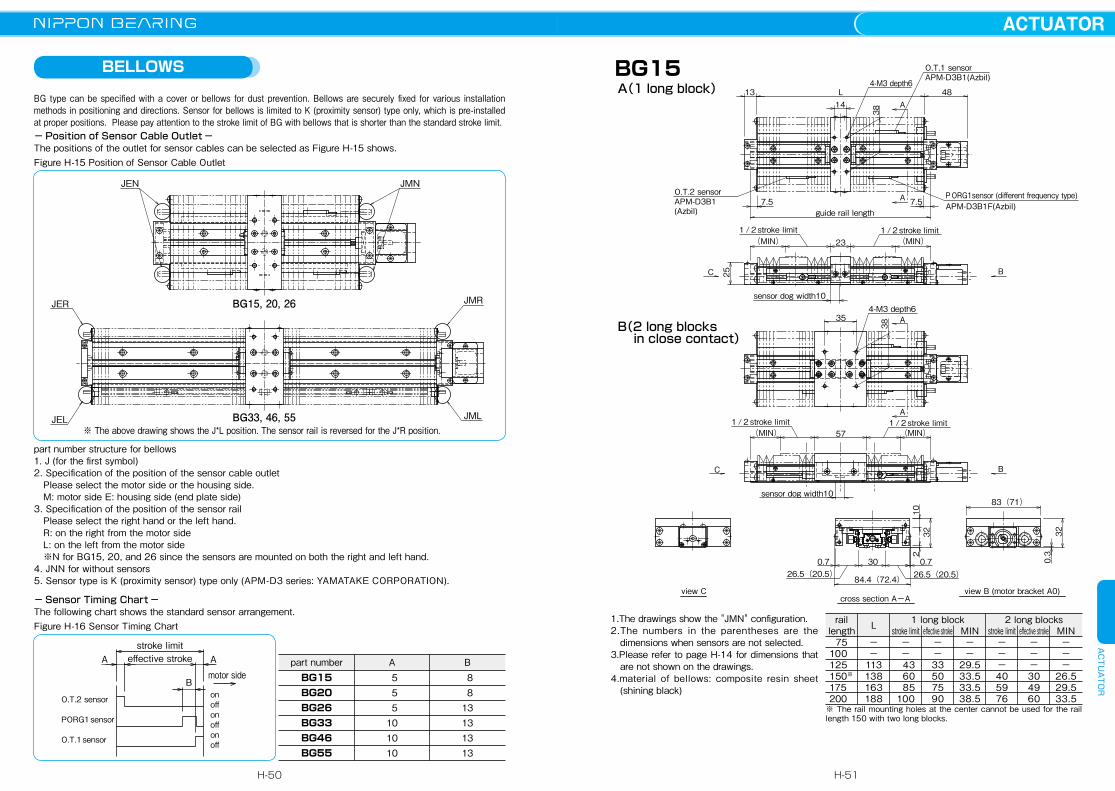
BELLOWS
BG type can be specified with a cover or bellows for dust prevention. Bellows are securely fixed for various installation methods in positioning and directions. Sensor for bellows is limited to K (proximity sensor) type only, which is pre-installed at proper positions. Please pay attention to the stroke limit of BG with bellows that is shorter than the standard stroke limit. − Position of Sensor Cable Outlet −The positions of the outlet for sensor cables can be selected as Figure H-15 shows.
− Sensor Timing Chart −The following chart shows the standard sensor arrangement.
ABG15BG20BG26BG33BG46BG55
5 5 5101010
part number B 8 813131313
Figure H-16 Sensor Timing Chart
Figure H-15 Position of Sensor Cable Outlet
JEN JMN
JER
JEL
JMR
JML
BG15, 20, 26
BG33, 46, 55※ The above drawing shows the J*L position. The sensor rail is reversed for the J*R position.
part number structure for bellows1. J (for the first symbol)2. Specification of the position of the sensor cable outlet Please select the motor side or the housing side. M: motor side E: housing side (end plate side)3. Specification of the position of the sensor rail Please select the right hand or the left hand. R: on the right from the motor side L: on the left from the motor side ※N for BG15, 20, and 26 since the sensors are mounted on both the right and left hand. 4. JNN for without sensors5. Sensor type is K (proximity sensor) type only (APM-D3 series: YAMATAKE CORPORATION).
B
A Astroke limiteffective stroke
motor side
onoffO.T.2 sensor
on
offonO.T.1 sensor
offPORG1 sensor
view Ccross section A-A
view B (motor bracket A0)
B(2 long blocks in close contact)
A(1 long block)BG15
B
BC
C
A14
A
A
A
7.5
L13
sensor dog width10
7.5guide rail length
231/2stroke limit 1/2stroke limit(MIN) (MIN)
26.5(20.5) 26.5(20.5)0.7 0.730
84.4(72.4)
38
4-M3 depth6
O.T.1 sensorAPM-D3B1(Azbil)
O.T.2 sensorAPM-D3B1(Azbil)
PORG1sensor (different frequency type)APM-D3B1F(Azbil)
83(71)
25
sensor dog width10
(MIN)(MIN)1/2stroke limit
38
35
1/2stroke limit57
4-M3 depth6
210
32 320.3
48
1.The drawings show the "JMN" configuration. 2.The numbers in the parentheses are the
dimensions when sensors are not selected. 3.Please refer to page H-14 for dimensions that
are not shown on the drawings.4.material of bellows: composite resin sheet
(shining black)
MIN−−−
26.529.533.5
effective stroke−−−304960
stroke limit−−−405976
MIN−−
29.533.533.538.5
effective stroke−−33507590
stroke limit−−
43 60 85100
−−
113138163188
75100125150※
175200
1 long block 2 long blocksLraillength
※ The rail mounting holes at the center cannot be used for the rail length 150 with two long blocks.
H-50
ACTUATORACTUATOR
H-51
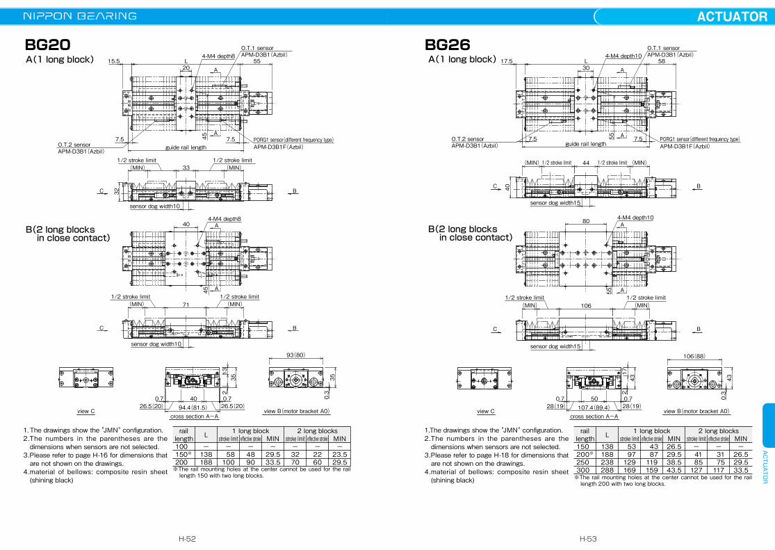
15.5 L 55
7.57.5 4545
235 35
0.3
13
32
O.T.1 sensorAPM-D3B1(Azbil)
PORG1 sensor(different frequency type)APM-D3B1F(Azbil)O.T.2 sensor
1/2 stroke limit
1/2 stroke limit 1/2 stroke limit
sensor dog width10
sensor dog width10
view C
1/2 stroke limit(MIN)
(MIN) (MIN)
(MIN)
APM-D3B1(Azbil)
20
guide rail length
33
40
71
A
A
A
A
C B
C
0.7 40
93(80)
26.5(20) 94.4(81.5) 26.5(20)0.7
B
4-M4 depth8
4-M4 depth8
BG20
view B(motor bracket A0)cross section A-A
B(2 long blocks in close contact)
A(1 long block)
1. The drawings show the "JMN" configuration. 2.The numbers in the parentheses are the
dimensions when sensors are not selected. 3.Please refer to page H-16 for dimensions that
are not shown on the drawings.4.material of bellows: composite resin sheet
(shining black)
MIN−
23.529.5
effective stroke−2260
stroke limit−3270
MIN−
29.533.5
effective stroke−4890
stroke limit−
58100
−138188
100150※
200
1 long block 2 long blocksLrail length
※The rail mounting holes at the center cannot be used for the rail length 150 with two long blocks.
L17.5 58
7.57.5
2
0.3
43 43
17
40
5555
O.T.1 sensorAPM-D3B1(Azbil)
PORG1 sensor(different frequency type)APM-D3B1F(Azbil)
O.T.2 sensor
sensor dog width15
sensor dog width15
1/2 stroke limit
1/2 stroke limit 1/2 stroke limit
1/2 stroke limit(MIN) (MIN)
(MIN) (MIN)
APM-D3B1(Azbil)
30
44
80
106
guide rail length
A
A
A
A
C B
0.7 5028(19) 107.4(89.4)
106(88)
28(19)0.7
4-M4 depth10
4-M4 depth10
BG26
view C view B(motor bracket A0)cross section A-A
BC
B(2 long blocks in close contact)
A(1 long block)
1.The drawings show the "JMN" configuration. 2.The numbers in the parentheses are the
dimensions when sensors are not selected. 3.Please refer to page H-18 for dimensions that
are not shown on the drawings.4.material of bellows: composite resin sheet
(shining black)
MIN−
26.529.533.5
effective stroke−
31 75117
stroke limit−
41 85127
MIN26.529.538.543.5
effective stroke 43 87119159
stroke limit 53 97129169
138188238288
150200※
250300
1 long block 2 long blocksLraillength
※The rail mounting holes at the center cannot be used for the rail length 200 with two long blocks.
H-52
ACTUATORACTUATOR
H-53
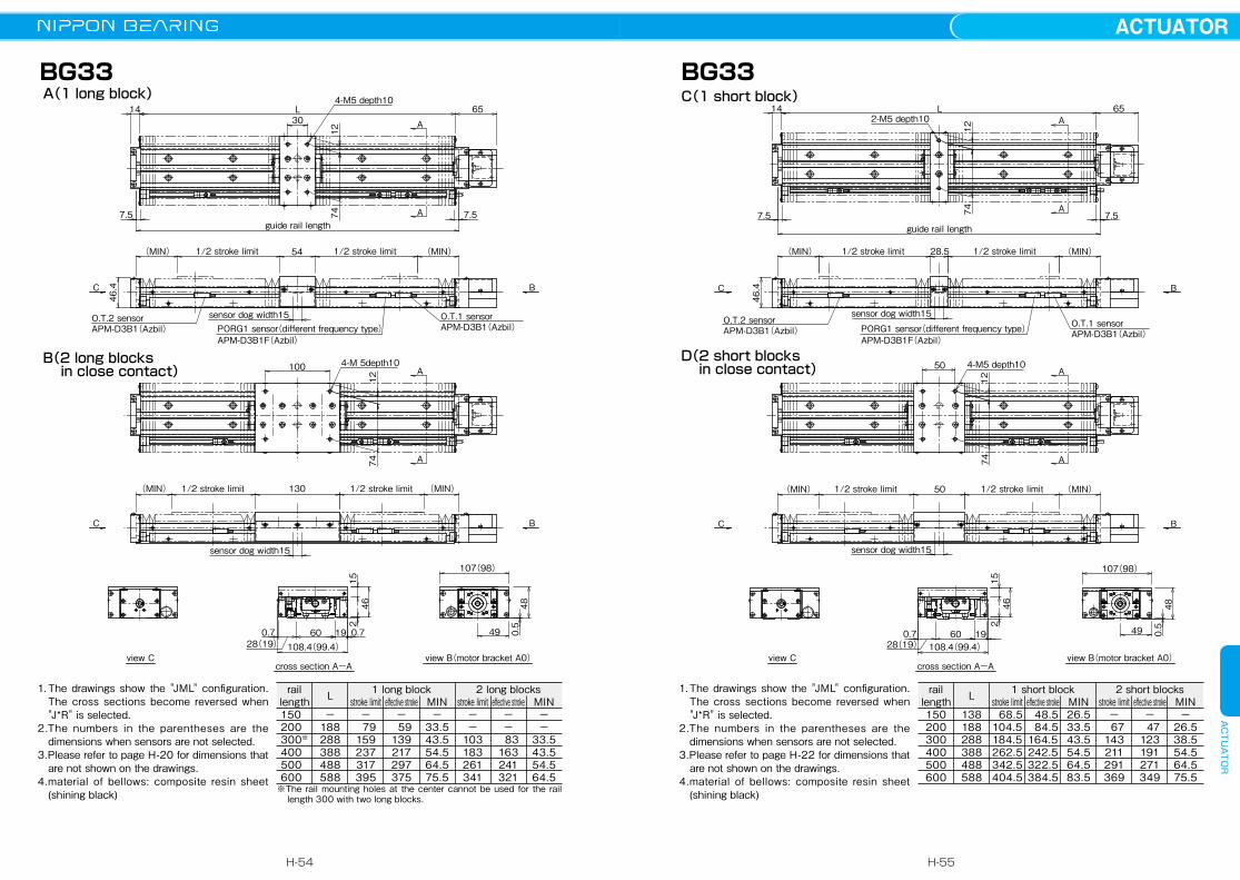
L
28.5
50
14
7.57.5
65
46 480.5
152
7412
7412
46.4
O.T.1 sensorAPM-D3B1(Azbil)PORG1 sensor(different frequency type)
APM-D3B1F(Azbil)
O.T.2 sensorsensor dog width15
sensor dog width15
1/2 stroke limit 1/2 stroke limit(MIN) (MIN)
501/2 stroke limit 1/2 stroke limit(MIN) (MIN)
APM-D3B1(Azbil)
guide rail length
A
A
A
A
C B
C B
0.7 60 491928(19) 108.4(99.4)
107(98)
2-M5 depth10
4-M5 depth10
BG33
view C view B(motor bracket A0)cross section A-A
D(2 short blocks in close contact)
C(1 short block)
1. The drawings show the "JML" configuration. The cross sections become reversed when "J*R" is selected.
2.The numbers in the parentheses are the dimensions when sensors are not selected.
3.Please refer to page H-22 for dimensions that are not shown on the drawings.
4.material of bellows: composite resin sheet (shining black)
MIN−
26.538.554.564.575.5
effective stroke−
47123191271349
stroke limit−
67143211291369
MIN26.533.543.554.564.583.5
effective stroke 48.5 84.5164.5242.5322.5384.5
stroke limit 68.5104.5184.5262.5342.5404.5
138188288388488588
150200300400500600
1 short block 2 short blocksLraillength
L14
7.5 7.5
65
46 480.5
152
7412
74
46.4
12
O.T.1 sensorAPM-D3B1(Azbil)PORG1 sensor(different frequency type)
APM-D3B1F(Azbil)
O.T.2 sensor sensor dog width15
sensor dog width15
1/2 stroke limit 1/2 stroke limit(MIN) (MIN)
1/2 stroke limit 1/2 stroke limit(MIN) (MIN)
APM-D3B1(Azbil)
30
54
100
130
guide rail length
A
A
A
A
C B
C B
0.7 0.760 491928(19) 108.4(99.4)
107(98)
4-M5 depth10
4-M 5depth10
BG33
view C view B(motor bracket A0)cross section A-A
B(2 long blocks in close contact)
A(1 long block)
1. The drawings show the "JML" configuration. The cross sections become reversed when "J*R" is selected.
2.The numbers in the parentheses are the dimensions when sensors are not selected.
3.Please refer to page H-20 for dimensions that are not shown on the drawings.
4.material of bellows: composite resin sheet (shining black)
MIN−−
33.543.554.564.5
effective stroke−−
83163241321
stroke limit−−
103183261341
MIN−
33.543.554.564.575.5
effective stroke−
59139217297375
stroke limit−
79159237317395
−188288388488588
150200300※
400500600
1 long block 2 long blocksLraillength
※The rail mounting holes at the center cannot be used for the rail length 300 with two long blocks.
H-54
ACTUATORACTUATOR
H-55
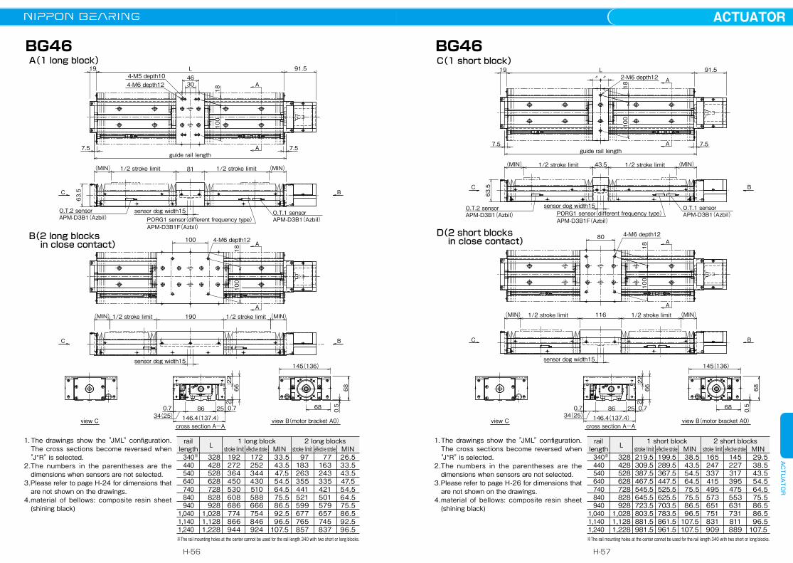
1. The drawings show the "JML" configuration. The cross sections become reversed when "J*R" is selected.
2.The numbers in the parentheses are the dimensions when sensors are not selected.
3.Please refer to page H-26 for dimensions that are not shown on the drawings.
4.material of bellows: composite resin sheet (shining black)
MIN 29.5 38.5 43.5 54.5 64.5 75.5 86.5 86.5 96.5107.5
effective stroke145227317395475553631731811889
stroke limit165247337415495573651751831909
MIN 38.5 43.5 54.5 64.5 75.5 75.5 86.5 96.5107.5107.5
effective stroke199.5289.5367.5447.5525.5625.5703.5783.5861.5961.5
stroke limit219.5309.5387.5467.5545.5645.5723.5803.5881.5981.5
328428528628728828928
1,0281,1281,228
340※
440 540 640 740 840 9401,0401,1401,240
1 short block 2 short blocksLraillength
※The rail mounting holes at the center cannot be used for the rail length 340 with two short or long blocks.
L
43.5
80
〃 〃91.519
7.5 7.5
2266 68
2
0.5
18100
18100
63.5
O.T.1 sensorAPM-D3B1(Azbil)PORG1 sensor(different frequency type)
APM-D3B1F(Azbil)
O.T.2 sensor sensor dog width15
sensor dog width15
1/2 stroke limit 1/2 stroke limit(MIN) (MIN)
1161/2 stroke limit 1/2 stroke limit(MIN) (MIN)
APM-D3B1(Azbil)
guide rail length
A
A
A
A
C B
C B
0.7 0.786 682534(25) 146.4(137.4)
145(136)
2-M6 depth12
4-M6 depth12
BG46
view C view B(motor bracket A0)cross section A-A
D(2 short blocks in close contact)
C(1 short block)L
30
81
100
190
4691.519
7.57.5
2266 68
2
0.5
18100
18100
63.5
O.T.1 sensorAPM-D3B1(Azbil)PORG1 sensor(different frequency type)
APM-D3B1F(Azbil)
O.T.2 sensor sensor dog width15
sensor dog width15
1/2 stroke limit 1/2 stroke limit(MIN) (MIN)
1/2 stroke limit 1/2 stroke limit(MIN) (MIN)
APM-D3B1(Azbil)
guide rail length
A
A
A
A
C B
C B
0.7 0.786 682534(25) 146.4(137.4)
145(136)
4-M5 depth104-M6 depth12
4-M6 depth12
BG46
view C view B(motor bracket A0)cross section A-A
B(2 long blocks in close contact)
A(1 long block)
1. The drawings show the "JML" configuration. The cross sections become reversed when "J*R" is selected.
2.The numbers in the parentheses are the dimensions when sensors are not selected.
3.Please refer to page H-24 for dimensions that are not shown on the drawings.
4.material of bellows: composite resin sheet (shining black)
MIN26.533.543.547.554.564.575.586.592.596.5
effective stroke 77163243335421501579657745837
stroke limit 97183263355441521599677765857
MIN 33.5 43.5 47.5 54.5 64.5 75.5 86.5 92.5 96.5107.5
effective stroke172252344430510588666754846924
stroke limit192272364450530608686774866944
328428528628728828928
1,0281,1281,228
340※
440 540 640 740 840 9401,0401,1401,240
1 long block 2 long blocksLraillength
※The rail mounting holes at the center cannot be used for the rail length 340 with two short or long blocks.
H-56
ACTUATORACTUATOR
H-57

L
50
140
218
95
10022.5
22.5
110
22.5
110
7.5 7.5
2578 80
2
0.5
74.5
O.T.1 sensorAPM-D3B1(Azbil)PORG1 sensor(different frequency type)
APM-D3B1F(Azbil)
O.T.2 sensor sensor dog width15
sensor dog width15
1/2 stroke limit 1/2 stroke limit(MIN) (MIN)
1/2 stroke limit 1/2 stroke limit(MIN) (MIN)
APM-D3B1(Azbil)
guide rail length
A
A
A
A
C B
C B
0.7 0.7100 77.527.538.5(27.5)
167.4(156.4)
166(155)
4-M8 depth16
4-M8 depth16
BG55
view C view B(motor bracket A0)cross section A-A
B(2 long blocks in close contact)
A(1 long block)
1. The drawings show the "JML" configuration. The cross sections become reversed when "J*R" is selected.
2.The numbers in the parentheses are the dimensions when sensors are not selected.
3.Please refer to page H-28 for dimensions that are not shown on the drawings.
4.material of bellows: composite resin sheet (shining black)
MIN64.575.586.586.596.5
effective stroke613691769869949
stroke limit633711789889969
MIN75.586.586.596.5
107.5
effective stroke714792892972
1,050
stroke limit 734812912992
1,070
9681,0681,1681,2681,368
9801,0801,1801,2801,380
1 long block 2 long blocksLraillength
SENSOR
Photomicro sensor or proximity sensor can be attached to the BG actuator with our optional sensor-mounting rail (the same length as the guide rail length). Tapped holes are machined on both sides of the guide rail, allowing attachment of sensor to either side. Standard positioning (without special instruction from customer) would be to the left of the motor mount end. Sensor option includes the items that are listed below.Three types of sensor rail are available. (see Figure H-17) For details, please refer to page H-59 〜 H-69.Depending on sizes, some sensor rail are not available.
sensor code sensor type BG15 BG20 BG26 BG33 BG46 BG55
S slim/compact typephotomicro sensor ――― PM-L24 [3pcs]※1
(SUNX)EE-SX674 [3pcs]※2
(OMRON)
H close contact capablephotomicro sensor ――― EE-SX671 [3pcs]※2
(OMRON)
K proximity sensor(N.C.contact)※3
APM-D3B1 [2pcs]※1
APM-D3B1F [1pcs]※1※4
(Azbil)※1:length of cable: 1m※2:3 pcs of sensor connector will be attached※3:normal close contact※4:different frequency type
sensorrail No.
part number
sensor rail1 sensor rail2 sensor rail3
35
13
357
1
3.4
15
5
75.6
2.4
8.515
4
12
16
27.4
3
5.619
3.3
5.5
86.5
24.4
BG15 ○ × ×BG20 ○ × ×BG26 ○ × ×BG33 ○ ○ ○BG46 ○ ○ ○BG55 ○ ○ ○
Table H-12 NPN Sensor
Figure H-17 Sensor rail
H-58
ACTUATORACTUATOR
H-59
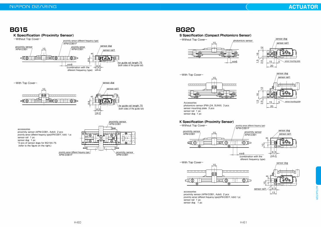
sensor rail1
sensor dog
810
13
6 5
proximity sensor
(combination with the diferent frequency type)
min8
10
8
6
10
sensor dog
12.7
sensor rail1
5
10
proximity sensorAPM-D3B1F
APM-D3B1 APM-D3B1
proximity sensor (different frequency type)
sensor mounting plate
sensor mounting plate
sensor rail1sensor dog
16
12
1.5
20
2.5 15 5
sensor rail1
sensor dog
16
12
1.5
20
2.5 15 5
-With Top Cover-
accessoriesproximity sensor (APM-D3B1, Azbil) 2 pcsproximity sensor (different frequency type)(APM-D3B1F, Azbil) 1 pcsensor rail 1 pc sensor dog 1 pc
Accessoriesphotomicro sensor (PM-L24, SUNX) 3 pcssensor mounting plate 3 pcssensor rail 1 pcsensor dog 1 pc
K Specification (Proximity Sensor)-Without Top Cover-
-With Top Cover-
S Specification (Compact Photomicro Sensor)-Without Top Cover-
10
min6
photomicro sensor10
BG20
accessoriesproximity sensor (APM-D3B1, Azbil) 2 pcsproximity sensor (different frequency type)(APM-D3B1F, Azbil) 1 pcsensor rail 1 pcsensor dog 1 pc*2 pcs of sensor dogs for BG15A-75 (refer to the figure on the right.)
-With Top Cover-
10proximity sensorAPM-D3B1
proximity sensor (different frequency type)APM-D3B1F
proximity sensorAPM-D3B1
min8(combination with the diferent frequency type)
sensor rail1
sensor dog
512.7
8.8
6
8sensor rail1
sensor dog
10
5612.7
8.8
8
proximity sensorAPM-D3B1
proximity sensor (different frequency type)APM-D3B1F
proximity sensorAPM-D3B1
for guide rail length 75(both sides of the guide rail)
for guide rail length 75(both sides of the guide rail)
K Specification (Proximity Sensor)-Without Top Cover-
BG15
H-60
ACTUATORACTUATOR
H-61

104.25
4.25
15 sensor dog
sensor rail2
31
1515.5
0.5
15
10
min21
15
sensor dog
sensor rail2
15.5
15
31
0.5
15
photomicro sensor
-With Top Cover-
long block
short block
short block
long block
-Without Top Cover-
S Specification (Slim-Type Photomicro Sensor)
accessoriesphotomicro sensor (EE-SX674, OMRON) 3 pcsconnector (EE-1001, OMRON) 3 pcssensor rail 1 pc sensor dog *1 pc* 2 pcs for BG33D-150.
connector
BG33
proximity sensorproximity sensorAPM-D3B1F
APM-D3B1APM-D3B1
proximity sensor (different frequency type)
sensor dog
sensor rail1
15
13
6 5
118
15
(combination with the different frequency type)
min8
sensor rail1sensor dog
811
5613
sensor mounting plate
sensor rail1sensor dog
20
17 12
3.5
15 5
sensor mounting plate
sensor rail1
sensor dog
20
17 12
1.5 3.5
15 5
-With Top Cover-
K Specification (Proximity Sensor)-Without Top Cover-
-With Top Cover-
S Specification (Compact Photomicro Sensor)-Without Top Cover-
Accessoriesphotomicro sensor (PM-L24, SUNX) 3 pcssensor mounting plate 3 pcssensor rail 1 pcsensor dog 1 pc
accessoriesproximity sensor (APM-D3B1, Azbil) 2 pcsproximity sensor (different frequency type)(APM-D3B1F, Azbil) 1 pcsensor rail 1 pc sensor dog 1 pc
1.5
min6
15
photomicro sensor15
BG26
H-62
ACTUATORACTUATOR
H-63

4.25 10
15
8
13
sensor dog
sensor rail1
13
56
15
4.25 10
15
sensor rail1
sensor dogproximity sensor
(combination with the different frequency type)
min8
proximity sensor (different frequency type)
APM-D3B1
APM-D3B1
APM-D3B1Fproximity sensor
1356
138
15
short block
-With Top Cover-
long block
short block
long block
-Without Top Cover-
K Specification (Proximity Sensor)
accessoriesproximity sensor (APM-D3B1, Azbil) 2 pcsproximity sensor (different frequency type)(APM-D3B1F, Azbil) 1 pcsensor rail 1 pc sensor dog *1 pc* 2 pcs for BG33D-150.
BG33
4.25 10
32
sensor rail3
sensor dog
15.5
160.5
27.4
15
33
21
sensor rail1
sensor mounting plate
sensor dog
28 5
15.5
1.8
3.7
short block
-With Top Cover-
long block
short block
long block
-Without Top Cover-
H Specification (Close Contact Capable Photomicro Sensor)
accessoriesphotomicro sensor (EE-SX671, OMRON) 3 pcsconnector (EE-1001, OMRON) 3 pcssensor mounting plate (only for the without cover type) 3 pcssensor rail 1 pcsensor dog *1 pcs* 2 pcs for BG33D-150.
min7
4.25 10
connector
photomicro sensor15
BG33
H-64
ACTUATORACTUATOR
H-65
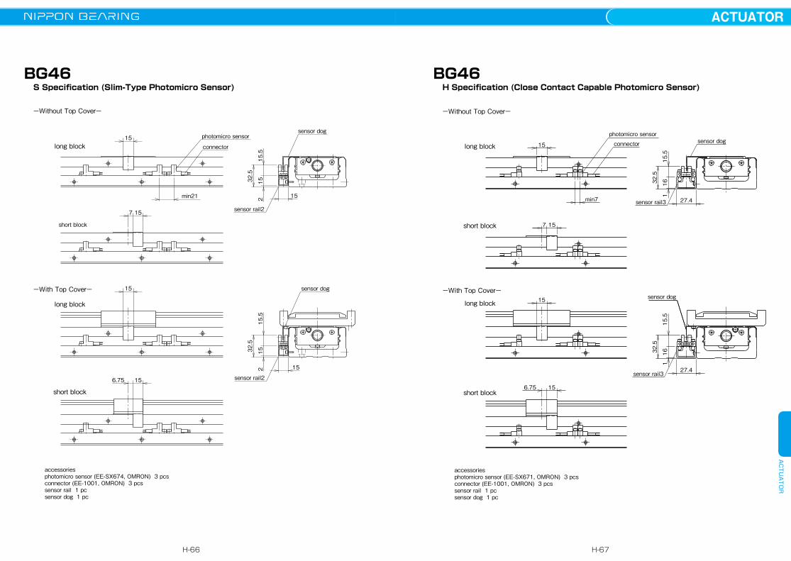
min7
6.75 15
32.5
27.4
sensor dog
sensor rail3
15.5
161
15
7 15
connector
32.5
27.4sensor rail3
sensor dog
15.5
161
15
photomicro sensor
short block
-With Top Cover-
long block
short block
long block
-Without Top Cover-
H Specification (Close Contact Capable Photomicro Sensor)
accessoriesphotomicro sensor (EE-SX671, OMRON) 3 pcsconnector (EE-1001, OMRON) 3 pcssensor rail 1 pc sensor dog 1 pc
BG46
6.75 15
15
32.5
15.5
152 15
sensor rail2
sensor dog
7 15
connector
min21
15 photomicro sensorsensor dog
sensor rail2
15215
15.5
32.5
-With Top Cover-
long block
short block
short block
long block
-Without Top Cover-
S Specification (Slim-Type Photomicro Sensor)
accessoriesphotomicro sensor (EE-SX674, OMRON) 3 pcsconnector (EE-1001, OMRON) 3 pcssensor rail 1 pc sensor dog 1 pc
BG46
H-66
ACTUATORACTUATOR
H-67

36
4.5
1615.5
27.4sensor rail3
sensor dog20
20
27.4
15.5
16
min7
photomicro sensorsensor dog
sensor rail3
connector
4.5
36
connector
sensor rail2
sensor dog
min21
20 photomicro sensor
4.5
1515.5
35
15
sensor rail2
4.515
15.5
35
15
sensor dog
20
-Without Top Cover-
H Specification (Close Contact Capable Photomicro Sensor)
-With Top Cover-
-With Top Cover-
S Specification (Compact Photomicro Sensor)
-Without Top Cover-
accessoriesphotomicro sensor (EE-SX674, OMRON) 3 pcsconnector (EE-1001, OMRON) 3 pcssensor rail 1 pc sensor dog 1 pc
accessoriesphotomicro sensor (EE-SX671, OMRON) 3 pcsconnector (EE-1001, OMRON) 3 pcssensor rail 1 pcsensor dog 1 pc
BG55
7 15
14.5
13
sensor rail1
8
56
15
sensor dog
7 15
14.5
sensor dog
13
APM-D3B1
APM-D3B1
APM-D3B1Fproximity sensorproximity sensor (different frequency type)
proximity sensor
(combination with the different frequency type)
min8 6 5sensor rail1
8
15
short block
-With Top Cover-
long block
short block
long block
-Without Top Cover-
K Specification (Proximity Sensor)
accessoriesproximity sensor (APM-D3B1, Azbil) 2 pcsproximity sensor (different frequency type)(APM-D3B1F, Azbil) 1 pcsensor rail 1 pc sensor dog 1 pc
BG46
H-68
ACTUATORACTUATOR
H-69
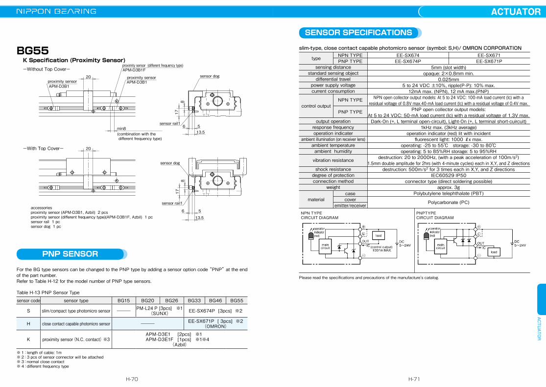
17
20
sensor dog
sensor rail1
6 5
8
13.5
17
(combination with the different frequency type)
min8
proximity sensor
proximity sensor (different frequency type)
APM-D3B1APM-D3B1
APM-D3B1F
proximity sensor20
sensor rail1
13.5
8
sensor dog
56
-With Top Cover-
K Specification (Proximity Sensor)-Without Top Cover-
accessoriesproximity sensor (APM-D3B1, Azbil) 2 pcsproximity sensor (different frequency type)(APM-D3B1F, Azbil) 1 pcsensor rail 1 pc sensor dog 1 pc
PNPTYPECIRCUIT DIAGRAM
type NPN TYPEPNP TYPE
sensing distancestandard sensing object
differential travelpower supply voltagecurrent consumption
control outputNPN TYPE
PNP TYPE
output operationresponse frequencyoperation indicater
ambient illumination (on receiver lens)ambient temperatureambient humidity
vibration resistance
shock resistancedegree of protectionconnection method
weight
materialcasecover
emitter/receiver
EE-SX674EE-SX674P
EE-SX671EE-SX671P
5mm (slot width)opaque: 2×0.8mm min.
0.025mm5 to 24 VDC ±10%, ripple(P-P): 10% max.
12mA max. (NPN), 12 mA max.(PNP)NPN open collector output models: At 5 to 24 VDC: 100-mA load current (lc) with a
residual voltage of 0.8V max.40-mA load current (lc) with a residual voltage of 0.4V max.PNP open collector output models:
At 5 to 24 VDC: 50-mA load current (lc) with a residual voltage of 1.3V max.Dark-On (+, L terminal open-circuit), Light-On (+, L terminal short-cuircuit)
1kHz max. (3kHz average)operation indicator (red) lit with incident
fluorescent light: 1000 ℓx max.operating: -25 to 55℃ storage: -30 to 80℃operating: 5 to 85%RH storage: 5 to 95%RH
destruction: 20 to 2000Hz, (with a peak acceleration of 100m/s2)1.5mm double amplitude for 2hrs (with 4-minute cycles) each in X,Y, and Z directions
destruction: 500m/s2 for 3 times each in X,Y, and Z directionsIEC60529 IP50
connector type (direct soldering possible)approx. 3g
Polybutylene telephthalate (PBT)
Polycarbonate (PC)
slim-type, close contact capable photomicro sensor (symbol: S,H)/ OMRON CORPORATION
NPN TYPECIRCUIT DIAGRAM
SENSOR SPECIFICATIONS
Please read the specifications and precautions of the manufacture's catalog.
PNP SENSOR
For the BG type sensors can be changed to the PNP type by adding a sensor option code “PNP” at the end of the part number.Refer to Table H-12 for the model number of PNP type sensors.
BG55
Table H-13 PNP Sensor Type
sensor code sensor type BG15 BG20 BG26 BG33 BG46 BG55
S slim/compact type photomicro sensor ――― PM-L24 P [3pcs] ※1(SUNX) EE-SX674P [3pcs] ※2
H close contact capable photomicro sensor ――― EE-SX671P [ 3pcs] ※2(OMRON)
K proximity sensor(N.C. contact) ※3 APM-D3E1 [2pcs] ※1 APM-D3E1F [1pcs] ※1※4
(Azbil)※ 1:length of cable: 1m※ 2:3 pcs of sensor connector will be attached※ 3:normal close contact※ 4:different frequency type
H-70
ACTUATORACTUATOR
H-71

DC10.8~26.4V30mA MAX.
brown
blackindicator lamp
blue load
main circuit
DC10.8~26.4V30mA MAX.
brown
blackindicator lamp
blue
main circuit
load
type NPN TYPEPNP TYPE
rated sensing distancestandard target object
differential travelrated supply voltage
operating voltage rangecurrent consumption
control outputNPN TYPE
PNP TYPE
operation modeoperating frequency
indicator lampsoperating temperature range
operating humidity rangeambient illumination(on receiver lens)
dielectric strengthinsulation resistancevibration resistance
voltage withstandabilityinsulation resistance
shock resistanceprotection
weight
APM-D3B1,APM-D3B1F(different-frequency type)APM-D3E1,APM-D3E1F(different-frequency type)
2.5mm±15%15×15mm, 1mm thick iron
15% max. of sensing distance12/24VDC
10.8 to 26.4 VDC (ripple voltage 10% max.)10mA max.
NPN transistor open collector switching current: 30mA max. (resistive load)voltage drop: 1V max. (switching current 30mA) output dielectric strength: 26.4VPNP transistor open collector switching current: 30mA max. (resistive load)voltage drop: 1V max. (switching current 30mA) output dielectric strength: 26.4V
normally closed (N.C.)120Hz
lights (red) when object approaches-10 to 55℃ storage: -25 to 70℃
35 to 85% RHfluorescent light: 1000lxmax.
1000V AC (50/60Hz) for one min. between case and electrically live metals50MΩ min. (by 500V DC megger )
10 to 55Hz, 1.5mm peak-to-peak amplitude, 2hrs in X, Y, and Z directions1000V AC(50/60Hz) for one min. between all supply terminals connected together and enclosure
50MΩ, or more( with 500V DC megger )500m/s2 3 times in Y,Y, and Z directions
IP67 (IEC 529)approx. 10g
proximity sensor (symbol: K)/ Azbil CORPORATION
Please read the specifications and precautions of the manufacture's catalog.
PNP TYPECIRCUIT DIAGRAM
NPN TYPECIRCUIT DIAGRAM
type NPN TYPEPNP TYPE
sensing rangeminimum sensing object
hysteresisrepeatability
supply voltagecurrent consumption
output
NPN TYPE
PNP TYPE
output operationresponse time
operation indicaterambient illuminanceambient temperatureambient humidity
voltage withstandabilityinsulation resistancevibration resistanceshock resistance
cableweight
material casecover
PM-L24PM-L24P
5mm (fixed)0.8×1.8mm min. opaque
0.05mm or less0.03mm or less
5 to 24 VDC ±10%, ripple(P-P) 10% or less15mA or less
NPN open-collector transistormaximum sink current: 50mA, applied voltage: 30VDC or less (between output and 0V)residual voltage: 0.7V or less (at 50mA sink current) 0.4V or less (at 16mA sink current)
PNP open-collector transistormaximum source current: 50mA, applied voltage: 30VDC or less (between output and +V)residual voltage: 0.7V or less (at 50mA sink current) 0.4V or less (at 16mA sink current)
Incorporated with 2 outputs: Light-ON/Dark-ONunder light received condition: 20㎲ or less under light interrupted condition: 100㎲ or less (response frequency: 1kHz or more)
vermilion LED (lights up under light received condition)fluorescent light: 1000ℓx at the light-receiving face
operating: -25 to 55℃ (No dew condensation or icing allowed.) storage: -30 to 80℃35 to 85% RH storage: 35 to 85%RH
1000V AC for one min. between all supply terminals connected together and enclosure50MΩ, or more, with 250V DC megger between all supply terminals connected togeter and enclosure10 to 2,000Hz frequency, 1.5mm amplitude in X, Y, and Z directions for two hours each15,000m/s2 acceleration (1,500 G approx.) in X, Y, and Z directions for three times each
0.09mm2 4-core cabtyre cable 1m longapprox. 10g
Polybutylene telephthalate (PBT)Polycarbonate
compact photomicro sensor (symbol: S)/ Panasonic Electric Works SUNX Co.,Ltd.
PNP TYPECIRCUIT DIAGRAM
NPN TYPECIRCUIT DIAGRAM
Please read the specifications and precautions of the manufacture's catalog.
H-72
ACTUATORACTUATOR
H-73

motor end
(PS Option)-With Top Cover-
BG15A,B
BG20A,B
2-φ3 depth5+0.014 0
38 ±0.03
44
23
※Please contact NB for the without-top-cover option or the“PW”option.
applied to PW option(connected by pins)
62
44
44
60
10
applied to PW option(connected by pins)
52
33
10 ±0.03
45 ±0.03
55 ±0.03
17 ±0.03
11
2940.2
2-φ3 +0.014
0 depth 5
※2-φ3 +0.014
0 depth 6.5
※2-φ3 +0.014
0
depth 3
motor end
motor end
※For some cases, a shallow counterbore of φ4 will be machined at the hole area with"※" to remove a hardened layer.
※For some cases, a shallow counterbore of φ4 will be machined at the hole area with "※" to remove a hardened layer.
motor end
(PS Option)-Without Top Cover-
BG26A,B
(PS Option)-Without Top Cover-
-With Top Cover-
motor end
-With Top Cover-
2-φ3 +0.014 0 depth 5
(long block)
(long block)
(long block)
POSITIONING PIN HOLE
For the BG type, positioning pin holes can be provided on the slide block and sub table by addingthe option code“PS”or“PW”in the end of the part number.The option code“PR”is used to provide the guide rail with positioning pin holes. When positioning pin holes are necessary on both the slide block/sub table and guide rail, please add the option code“PSR”or“PWR”
Positioning Pin Hole for Slide Block and Sub TableIt is useful when exacting reassembly positioning is required. In case of two blocks used, both blocks are processed.When the code“PS”is added, the drilling is processed only on the mounting surface(slide block or sub table). When the code“PW”is specified for a BG with a top cover (except for BG15), the slide block and sub table are connected by the straight pins at the location where the“PS”option specifies on the slide block.Note that NB does not supply straight pins for the“PS”option.
Table H-14 Chart For Positioning
Chart For Positioning Pin hole
Slide Blockand Sub tablewith positioninpin hole
Guide Railswith Positioning
pin Hole
Option Code
When repeated work piece mounting accuracy is required.
When repeated actuator mounting accuracy is required.
When actuator sustains axial load causing a sub-table or a work piece to miss align from a carriage block such as in vertical orientation and high acceleration condition.
+ +
●without cover
●with cover
●with cover
PS PSR PR PWR PW
pin hole
pin hole
connected bythe straight pin
pin hole
pin hole
H-74
ACTUATORACTUATOR
H-75

2-φ4 +0.018 0 depth 6
※2-φ4 +0.018 0 depth 6
(PS Option)-Without Top Cover- -With Top Cover-
BG55A,B
applied to PW option(connected by pins)
95
124
37.5
95121123
42 ±0.03
110 ±0.03
2-φ4 +0.018 0 depth 6
※2-φ4 +0.018 0 depth 6
motor endmotor end
motor endmotor end
(PS Option)-Without Top Cover-
BG46C,D-With Top Cover-
12
applied to PW option(connected by pins)
112
43.5
12
70.644
73.2
42 ±0.03 100 ±0.03
2-φ4 +0.018 0
depth 6
※2-φ4 +0.018
0
depth 6 motor end
(PS Option)-Without Top Cover-
motor end
-With Top Cover-
BG46A,B
applied to PW option(connected by pins)
112
81
80106.6109.2
14
42 ±0.03
100 ±0.03
※For some cases, a shallow counterbore of φ5 will be machined at the hole area with "※" to remove a hardened layer.
※For some cases, a shallow counterbore of φ5 will be machined at the hole area with "※" to remove a hardened layer.
※For some cases, a shallow counterbore of φ5 will be machined at the hole area with "※" to remove a hardened layer.
(long block)
(short block)
(long block)
applied to PW option(connected by pins) 2-φ3 +0.014 0
depth 6
2-φ3 +0.014 0 depth 6
※2-φ3 +0.014 0
depth 6
※2-φ3 +0.014 0 depth 6
motor end
motor end
motor end
(PS Option)-Without Top Cover-
BG33C,D-With Top Cover-
(PS Option)-Without Top Cover-
motor end
-With Top Cover-
BG33A,B
8applied to PW option(connected by pins)
86
28.5
9
49.151.9
28.5
86
5422
53.8
74.4
77.225 ±0.03
25 ±0.03
74 ±0.03
74 ±0.03
※For some cases, a shallow counterbore of φ4 will be machined at the hole area with "※" to remove a hardened layer.
※For some cases, a shallow counterbore of φ4 will be machined at the hole area with "※" to remove a hardened layer.
(long block)
(short block)
H-76
ACTUATORACTUATOR
H-77
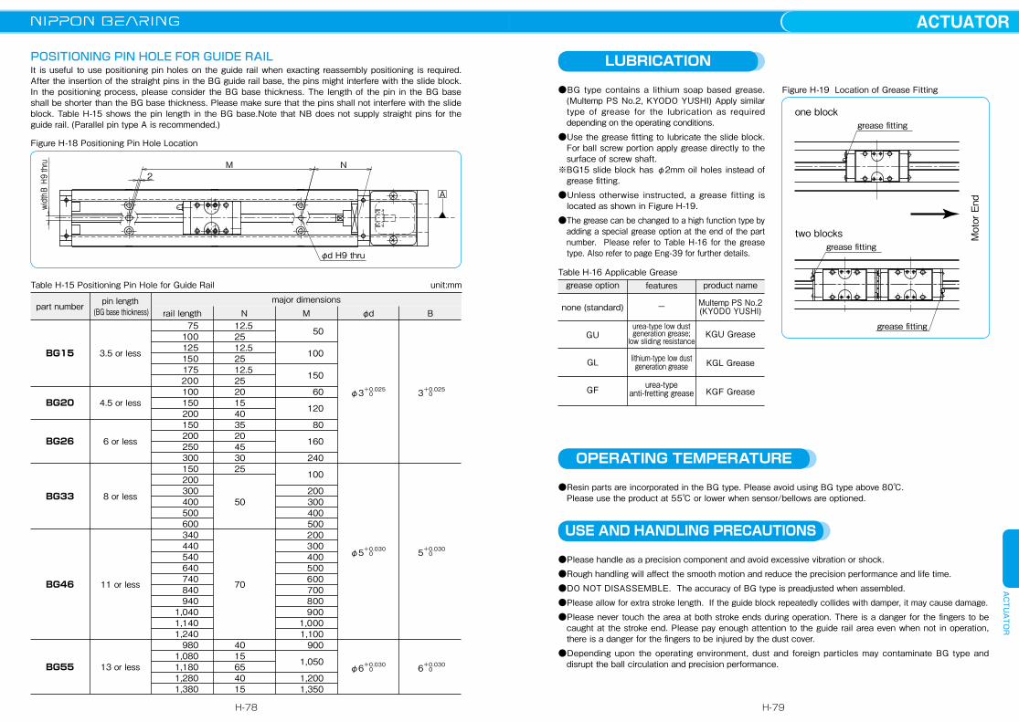
LUBRICATION
●BG type contains a lithium soap based grease.(Multemp PS No.2, KYODO YUSHI) Apply similar type of grease for the lubrication as required depending on the operating conditions.
●Use the grease fitting to lubricate the slide block. For ball screw portion apply grease directly to the surface of screw shaft.
※BG15 slide block has φ2mm oil holes instead of grease fitting.
●Unless otherwise instructed, a grease fitting is located as shown in Figure H-19.
●The grease can be changed to a high function type by adding a special grease option at the end of the part number. Please refer to Table H-16 for the grease type. Also refer to page Eng-39 for further details.
Figure H-19 Location of Grease Fitting
Table H-16 Applicable Greasegrease option
none (standard)
GU
GL
GF
product name
Multemp PS No.2 (KYODO YUSHI)
KGU Grease
KGL Grease
KGF Grease
grease fitting
grease fittingone block
two blocks
grease fitting
Motor End
OPERATING TEMPERATURE
●Resin parts are incorporated in the BG type. Please avoid using BG type above 80℃. Please use the product at 55℃ or lower when sensor/bellows are optioned.
USE AND HANDLING PRECAUTIONS
●Please handle as a precision component and avoid excessive vibration or shock. ●Rough handling will affect the smooth motion and reduce the precision performance and life time. ●DO NOT DISASSEMBLE. The accuracy of BG type is preadjusted when assembled. ●Please allow for extra stroke length. If the guide block repeatedly collides with damper, it may cause damage.●Please never touch the area at both stroke ends during operation. There is a danger for the fingers to be
caught at the stroke end. Please pay enough attention to the guide rail area even when not in operation, there is a danger for the fingers to be injured by the dust cover.
●Depending upon the operating environment, dust and foreign particles may contaminate BG type and disrupt the ball circulation and precision performance.
features
−
urea-type low dust generation grease;
low sliding resistance
lithium-type low dust generation grease
urea-type anti-fretting grease
POSITIONING PIN HOLE FOR GUIDE RAILIt is useful to use positioning pin holes on the guide rail when exacting reassembly positioning is required.After the insertion of the straight pins in the BG guide rail base, the pins might interfere with the slide block.In the positioning process, please consider the BG base thickness. The length of the pin in the BG base shall be shorter than the BG base thickness. Please make sure that the pins shall not interfere with the slide block. Table H-15 shows the pin length in the BG base.Note that NB does not supply straight pins for the guide rail. (Parallel pin type A is recommended.)
Figure H-18 Positioning Pin Hole Location
Table H-15 Positioning Pin Hole for Guide Rail
A
NM2
φd H9 thru
widthB H9 thru
BG15
BG20
BG26
BG33
BG46
BG55
3.5 or less
4.5 or less
6 or less
8 or less
11 or less
13 or less
75100125150175200
100 150 200 150 200 250 300 150 200 300 400 500 600 340 440 540 640 740 840 9401,0401,1401,240 9801,0801,1801,2801,380
12.5 25 12.5 25 12.5 25 20 15 40 35 20 45 30 25
50
70
40 15 65 40 15
50
100
150
60
120
80
160
240
100
200300400500200300400500600700800900
1,0001,100
900
1,050
1,2001,350
+0.025φ3 0+0.0253 0
+0.030φ5 0+0.0305 0
+0.030φ6 0+0.0306 0
part number pin length (BG base thickness) rail length
major dimensionsN M φd B
unit:mm
H-78
ACTUATORACTUATOR
H-79


