
1
Model SRPMRoom Pressure Monitor
Installation and Operating Manual
28
13.0 RETURNING PRODUCTS FOR REPAIRBefore returning the unit for repair, please contact a Setra application engineer (800-257-3872, 978-263-1400) to review information relative to your application . Many times only minor fi eld adjustments may be necessary. When returning a product to Setra, the unit should be carefully packaged and shipped prepaid to: Setra Systems, Inc. 159 Swanson Road Boxborough, MA 01719-1304 Attn: Repair Department
To assure prompt handling, please refer to return instructions on our Web site at
http://www.setra.com/tra/repairs/cal_rep.htm.
Allow approximately 3 weeks after receipt at Setra for the repair and return of the unit.Non-warranty repairs will not be made without customer approval and a purchase order to cover repair charges.
Calibration ServicesSetra maintains a complete calibration facility that is traceable to the National Institute of Standards & Technology (NIST). If you would like to recalibrate or recertify your Setra pressure transducers or transmitters, please call our Repair Department at 800-257-3872 (978-263-1400)
for scheduling.
14.0 WARRANTY AND LIMITATIONS OF LIABILITYSetra warrants its products to be free from defects in materials and workmanship, subject to the following terms and conditions:Without charge, Setra will repair or replace products to be found to be defective in materials or workmanship within the warranty period; provided that:a.) the product has not been subjected to abuse, neglect, accident, incorrect wiring not our own, improper installation or servicing, or use in violation of instructions furnished by Setra;b.) the product has not been repaired or altered by anyone except SETRA or its authorized service agencies;c) the serial number or product code has not been removed, defaced, or otherwise changed; andd) examination discloses, in the judgement of SETRA, the defect in materials or workmanship developed under normal installation, use and service;e) SETRA is notifi ed in advance of and the product is returned to SETRA transportation prepaid.Unless otherwise specifi ed in a manual or warranty card, or agreed to in a writing signed by a SETRA offi cer, SETRA pressure and acceleration products shall be warranted for one year from date of sale.The foregoing warranty is in lieu of all warranties, express, implied or statutory, including but not limited to, any implied warranty of merchantability for a particular purpose.SETRA’s liability for breach of warranty is limited to repair or replacement, or if the goods cannot be repaired or replaced, to a refund of the purchase price. SETRA’s liability for all other breaches is limited to a refund of the purchase price. In no instance shall SETRA be liable for incidental or conse-quential damages arising from a breach of warranty, or from the use or installation of its products.No representative or person is authorized to give any warranty other than as set out above or to assume for SETRA any other liability in connection with the sale of its products.
159 Swanson Road, Boxborough, MA 01719, 159 Swanson Road, Boxborough, MA 01719, Tel: 800-257-3872; Fax: 978-264-0292; Tel: 800-257-3872; Fax: 978-264-0292;
Email: [email protected]; Web: www.setra.comEmail: [email protected]; Web: www.setra.comSS-SRPM Rev. B 9/2/2008
2
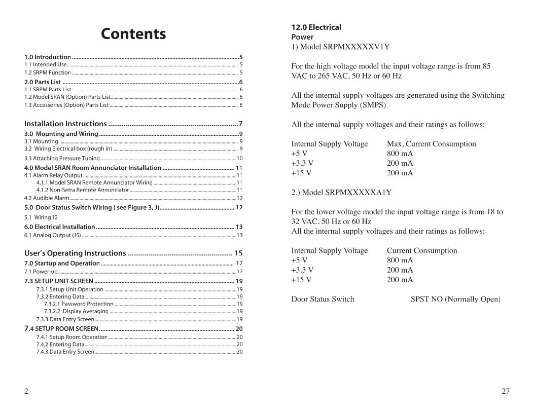
Contents1.0 Introduction .........................................................................................................51.1 Intended Use .........................................................................................................................................51.2 SRPM Function .....................................................................................................................................5
2.0 Parts List ...............................................................................................................61.1 SRPM Parts List .....................................................................................................................................61.2 Model SRAN (Option) Parts List ...................................................................................................... 61.3 Accessories (Option) Parts List ....................................................................................................... 6
Installation Instructions ....................................................................73.0 Mounting and Wiring ........................................................................................93.1 Mounting ..............................................................................................................................................93.2 Wiring Electrical box (rough in) .................................................................................................... 9
3.3 Attaching Pressure Tubing ............................................................................................................10
4.0 Model SRAN Room Annunciator Installation ............................................. 114.1 Alarm Relay Output ..........................................................................................................................11 4.1.1 Model SRAN Remote Annunciator Wiring ..................................................................11 4.1.2 Non-Setra Remote Annunciator .....................................................................................114.2 Audible Alarm .....................................................................................................................................12
5.0 Door Status Switch Wiring ( see Figure 3, J) ............................................... 12
5.1 Wiring 12
6.0 Electrical Installation ....................................................................................... 136.1 Analog Output (J5) ...........................................................................................................................13
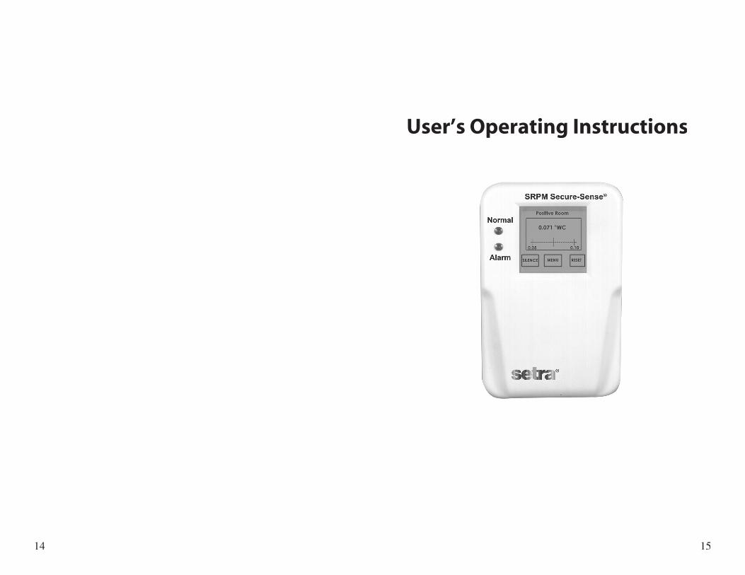
User’s Operating Instructions ....................................................... 157.0 Startup and Operation ................................................................................................ 177.1 Power-up ..............................................................................................................................................17
7.3 SETUP UNIT SCREEN ........................................................................................ 197.3.1 Setup Unit Operation .........................................................................................................197.3.2 Entering Data .........................................................................................................................19
7.3.2.1 Password Protection .................................................................................................19 7.3.2.2 Display Averaging .....................................................................................................19
7.3.3 Data Entry Screen .................................................................................................................19
7.4 SETUP ROOM SCREEN ..................................................................................... 207.4.1 Setup Room Operation ......................................................................................................207.4.2 Entering Data .........................................................................................................................207.4.3 Data Entry Screen .................................................................................................................20
27
12.0 ElectricalPower1) Model SRPMXXXXXV1Y
For the high voltage model the input voltage range is from 85 VAC to 265 VAC, 50 Hz or 60 Hz
All the internal supply voltages are generated using the Switching Mode Power Supply (SMPS).
All the internal supply voltages and their ratings as follows:
Internal Supply Voltage Max. Current Consumption+5 V 800 mA+3.3 V 200 mA+15 V 200 mA
2.) Model SRPMXXXXXA1Y
For the lower voltage model the input voltage range is from 18 to 32 VAC, 50 Hz or 60 HzAll the internal supply voltages and their ratings as follows:
Internal Supply Voltage Current Consumption+5 V 800 mA+3.3 V 200 mA+15 V 200 mA
Door Status Switch SPST NO (Normally Open)
3
Contents (cont’d)
7.5 SETUP ALARM SCREEN .............................................................. 21 7.5.1 Alarm Setup Operation ......................................................................................................21
7.5.2 Entering Data .........................................................................................................................21 7.5.2.1 Mute Time Out/Alarm Delay ..................................................................................21 7.5.3 Data Entry Screen .................................................................................................................217.6 SELF TEST SCREEN ............................................................................................ 22 7.6.1 Self Test Operation ..............................................................................................................227.7 CALIBRATION SCREEN ............................................................................22
7.7.1 Calibration ..............................................................................................................................22
8.8 Pressure Monitoring Screens ................................................................23
9.0 Maintenance ...........................................................................................25
9.1 Cleaning ..................................................................................................2510.0 Agency Electrical Standards ................................................................2511.0 SRPM Specifi cations ...........................................................................2612.0 Electrical ................................................................................................2713.0 RETURNING PRODUCTS FOR REPAIR ..................................................2814.0 Warranty and Limitations of Liability .................................................28
26
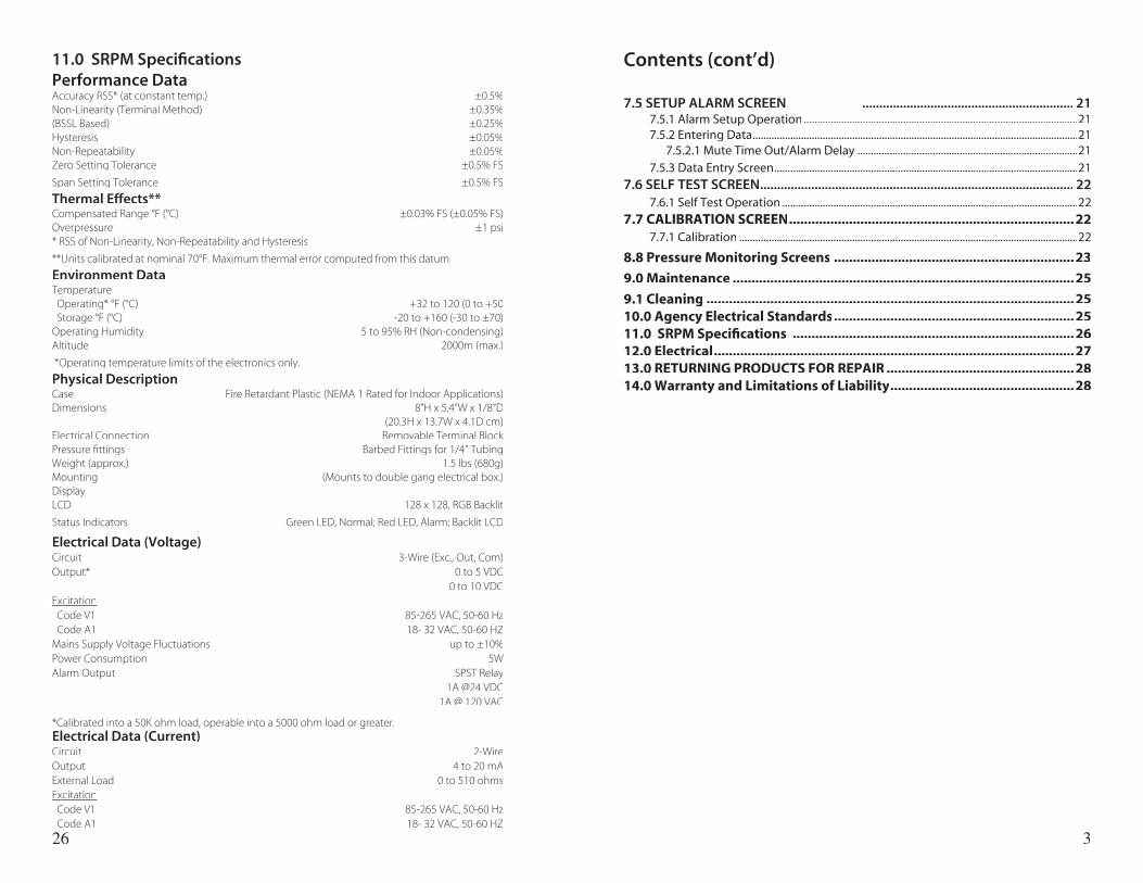
11.0 SRPM Specifi cations Performance DataAccuracy RSS* (at constant temp.) ±0.5%Non-Linearity (Terminal Method) ±0.35%(BSSL Based) ±0.25%Hysteresis ±0.05%Non-Repeatability ±0.05%Zero Setting Tolerance ±0.5% FS
Span Setting Tolerance ±0.5% FS
Thermal Effects**Compensated Range °F (°C) ±0.03% FS (±0.05% FS)Overpressure ±1 psi* RSS of Non-Linearity, Non-Repeatability and Hysteresis
**Units calibrated at nominal 70°F. Maximum thermal error computed from this datum.
Environment DataTemperature Operating* °F (°C) +32 to 120 (0 to +50 Storage °F (°C) -20 to +160 (-30 to ±70)Operating Humidity 5 to 95% RH (Non-condensing)Altitude 2000m (max.)
*Operating temperature limits of the electronics only.
Physical DescriptionCase Fire Retardant Plastic (NEMA 1 Rated for Indoor Applications)Dimensions 8”H x 5.4”W x 1/8”D (20.3H x 13.7W x 4.1D cm)Electrical Connection Removable Terminal BlockPressure fi ttings Barbed Fittings for 1/4” TubingWeight (approx.) 1.5 lbs (680g)Mounting (Mounts to double gang electrical box.)Display LCD 128 x 128, RGB Backlit
Status Indicators Green LED, Normal; Red LED, Alarm; Backlit LCD
Electrical Data (Voltage) Circuit 3-Wire (Exc., Out, Com)Output* 0 to 5 VDC 0 to 10 VDCExcitation Code V1 85-265 VAC, 50-60 Hz Code A1 18- 32 VAC, 50-60 HZMains Supply Voltage Fluctuations up to ±10%Power Consumption 5WAlarm Output SPST Relay 1A @24 VDC 1A @ 120 VAC
*Calibrated into a 50K ohm load, operable into a 5000 ohm load or greater.Electrical Data (Current) Circuit 2-WireOutput 4 to 20 mAExternal Load 0 to 510 ohmsExcitation Code V1 85-265 VAC, 50-60 Hz Code A1 18- 32 VAC, 50-60 HZ
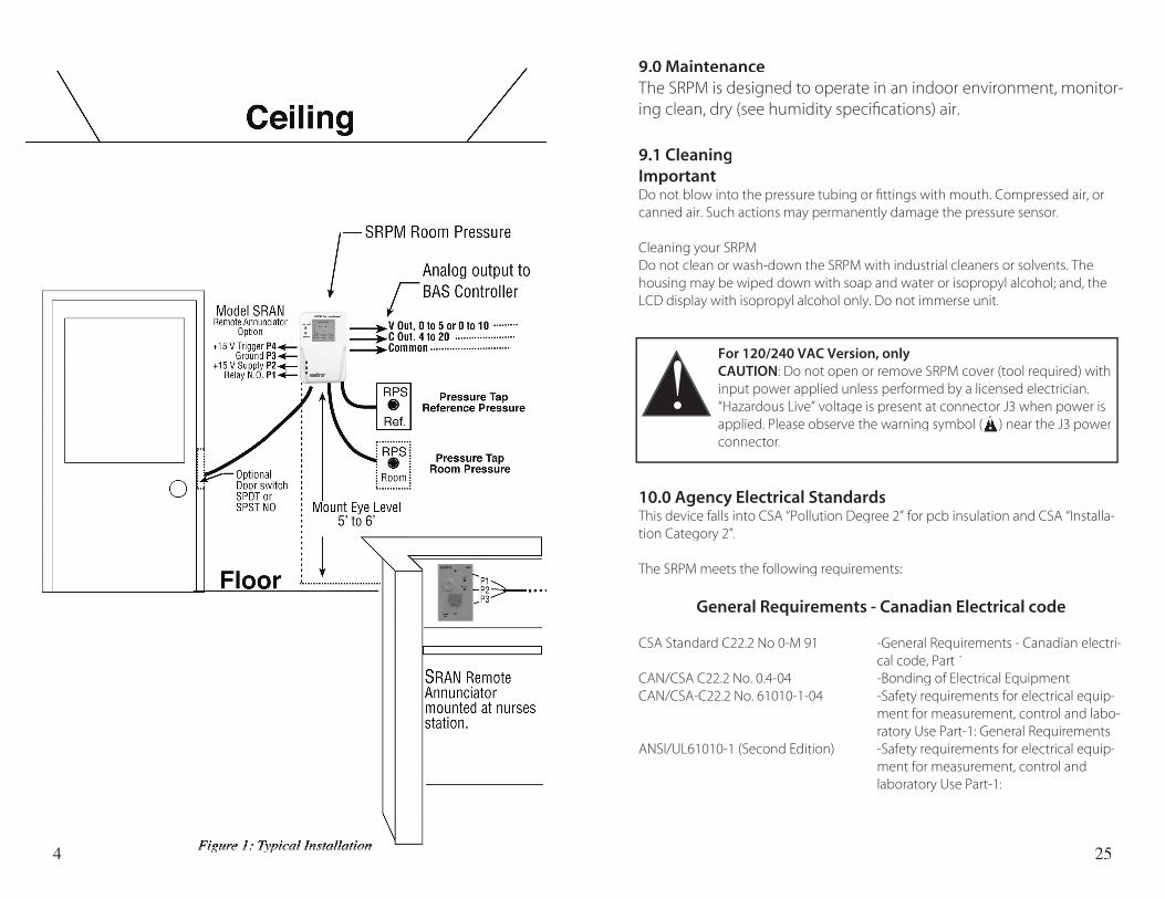
4 Figure 1: Typical InstallationFigure 1: Typical Installation 25
9.0 MaintenanceThe SRPM is designed to operate in an indoor environment, monitor-ing clean, dry (see humidity specifi cations) air.
9.1 CleaningImportantDo not blow into the pressure tubing or fi ttings with mouth. Compressed air, or canned air. Such actions may permanently damage the pressure sensor.
Cleaning your SRPMDo not clean or wash-down the SRPM with industrial cleaners or solvents. The housing may be wiped down with soap and water or isopropyl alcohol; and, the LCD display with isopropyl alcohol only. Do not immerse unit.
For 120/240 VAC Version, onlyCAUTION: Do not open or remove SRPM cover (tool required) with input power applied unless performed by a licensed electrician. “Hazardous Live” voltage is present at connector J3 when power is applied. Please observe the warning symbol ( ) near the J3 power connector.
10.0 Agency Electrical StandardsThis device falls into CSA “Pollution Degree 2” for pcb insulation and CSA “Installa-tion Category 2”.
The SRPM meets the following requirements:
General Requirements - Canadian Electrical code
CSA Standard C22.2 No 0-M 91 -General Requirements - Canadian electri-cal code, Part 1
CAN/CSA C22.2 No. 0.4-04 -Bonding of Electrical EquipmentCAN/CSA-C22.2 No. 61010-1-04 -Safety requirements for electrical equip-
ment for measurement, control and labo-ratory Use Part-1: General Requirements
ANSI/UL61010-1 (Second Edition) -Safety requirements for electrical equip-ment for measurement, control and laboratory Use Part-1:
!applied. Please observe the warning symbol ( ) near the J3 power applied. Please observe the warning symbol ( ) near the J3 power applied. Please observe the warning symbol ( ) near the J3 power !
5
1.0 IntroductionCongratulations, and thank you for purchasing Setra’s Room Pressure Monitor (Model SRPM). Its ease of operation and durable construction will provide years of reliable service. While the SRPM is easy to operate, it is advisable to read this guide carefully before use. It is designed to help you take full advantage of the function and performance of the SRPM.
1.1 Intended UseThe SRPM is designed to monitor critical air environments, providing room static pressure indication, alarming, and communication functions. The applications include:
1.) hospitals - patient isolation and protection rooms, operating suites, intensive care and emergency rooms.
2.) pharmaceutical, semiconductor, and precision manufacturing and clean rooms.
3.) laboratories - medical research and BSLs (Bio-Safety Labs), radiation, toxic metals and chemicals.
1.2 SRPM FunctionThe SRPM senses very low differential pressure using Setra’s patented, high accu-racy capacitive sensor technology. The pressure difference for these application is the difference in static pressure between a critical environment room and its surrounding reference area ( usually a hallway or another room) see Figure 1.
Maintaining and monitoring a static room pressure difference insures that the critical environment room is either protected or isolated from a surrounding environment. Protection strategy requires a net positive room static pressure difference, while isolation requires a net negative static pressure difference. The SRPM can be programmed to monitor either positive or negative room static pressure. The SRPM low pressure sensing technology is coupled with multifunc-tional alarming and simple, intuitive touch-screen user interface with selectable security protection.
24
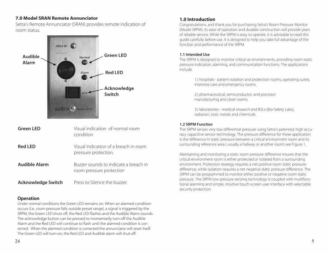
7.0 Model SRAN Remote Annunciator Setra’s Remote Annunciator (SRAN) provides remote indication of room status.
Green LED
Red LED
Acknowledge Switch
AudibleAlarm
Green LED Visual indication of normal room condition
Red LED Visual Indication of a breach in room pressure protection.
Audible Alarm Buzzer sounds to indicate a breach in room pressure protection
Acknowledge Switch Press to Silence the buzzer.
OperationUnder normal conditions the Green LED remains on. When an alarmed condition occurs (i.e., room pressure falls outside preset range), a signal is triggered by the SRPM, the Green LED shuts off, the Red LED fl ashes and the Audible Alarm sounds. The acknowledge button can be pressed to momentarily turn-off the Audible Alarm and the Red LED will continue to fl ash until the alarmed condition is cor-rected. When the alarmed condition is corrected the annunciator will reset itself. The Green LED will turn-on, the Red LED and Audible alarm will shut-off.
6
2.0 Parts List
2.1 SRPM Parts List
Qty(1) Setra SRPM assembly
(2) Barbed Coupling, Brass Plated (2) 1/4 inch Tube, Silicone, Inter-Connect (4) 6-32 x 1/2” Mounting Screws for SRPM Base
Not Included: Supplied by User (2) Single Gang Electrical Box for RPS Plates (1) Double Gang Metal Electrical Box with Grounding Stud (1) 4 x 4 inch Metal Plaster Ring (1) Door Switch SPDT or SPST, N.O., as needed
2.2 Model SRAN (Option) Parts List
Qty (1) Annunciator Assembly
Not Included: Supplied by User (1) Single Gang Electrical Box
2.3 Accessories (Option) Parts List
Qty (2) Part # RPS, Static Pressure Fitting Plate
Not Included, Supplied by User (2) Single Gang Electrical box for RPS Plates
23
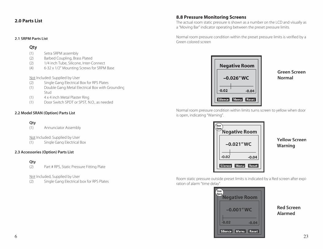
8.8 Pressure Monitoring ScreensThe actual room static pressure is shown as a number on the LCD and visually as a “Moving Bar” indicator operating between the preset pressure limits.
Normal room pressure condition within the preset pressure limits is verifi ed by a Green colored screen
Normal room pressure condition within limits turns screen to yellow when door is open, indicating “Warning”.
Room static pressure outside preset limits is indicated by a Red screen after expi-ration of alarm “time delay”.
Green Screen Normal
Yellow ScreenWarning
Red ScreenAlarmed
7
Installation Instructions
22
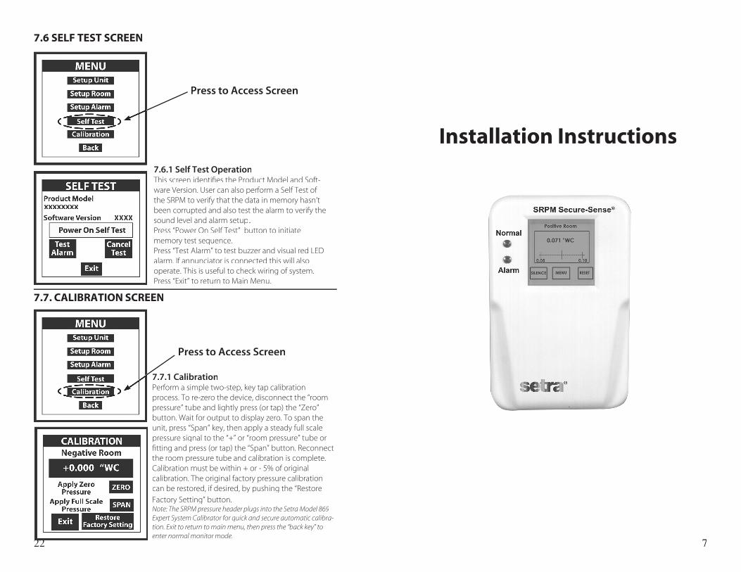
7.6.1 Self Test OperationThis screen identifi es the Product Model and Soft-ware Version. User can also perform a Self Test of the SRPM to verify that the data in memory hasn’t been corrupted and also test the alarm to verify the sound level and alarm setup. Press “Power On Self Test” button to initiate memory test sequence.Press “Test Alarm” to test buzzer and visual red LED alarm. If annunciator is connected this will also operate. This is useful to check wiring of system.Press “Exit” to return to Main Menu.
7.7.1 CalibrationPerform a simple two-step, key tap calibration process. To re-zero the device, disconnect the “room pressure” tube and lightly press (or tap) the “Zero” button. Wait for output to display zero. To span the unit, press “Span” key, then apply a steady full scale pressure signal to the “+” or “room pressure” tube or fi tting and press (or tap) the “Span” button. Reconnect the room pressure tube and calibration is complete. Calibration must be within + or - 5% of original calibration. The original factory pressure calibration can be restored, if desired, by pushing the “Restore Factory Setting” button. Note: The SRPM pressure header plugs into the Setra Model 869 Expert System Calibrator for quick and secure automatic calibra-tion. Exit to return to main menu, then press the “back key” to enter normal monitor mode.
7.6 SELF TEST SCREEN
Press to Access Screen
7.7. CALIBRATION SCREEN
Press to Access Screen
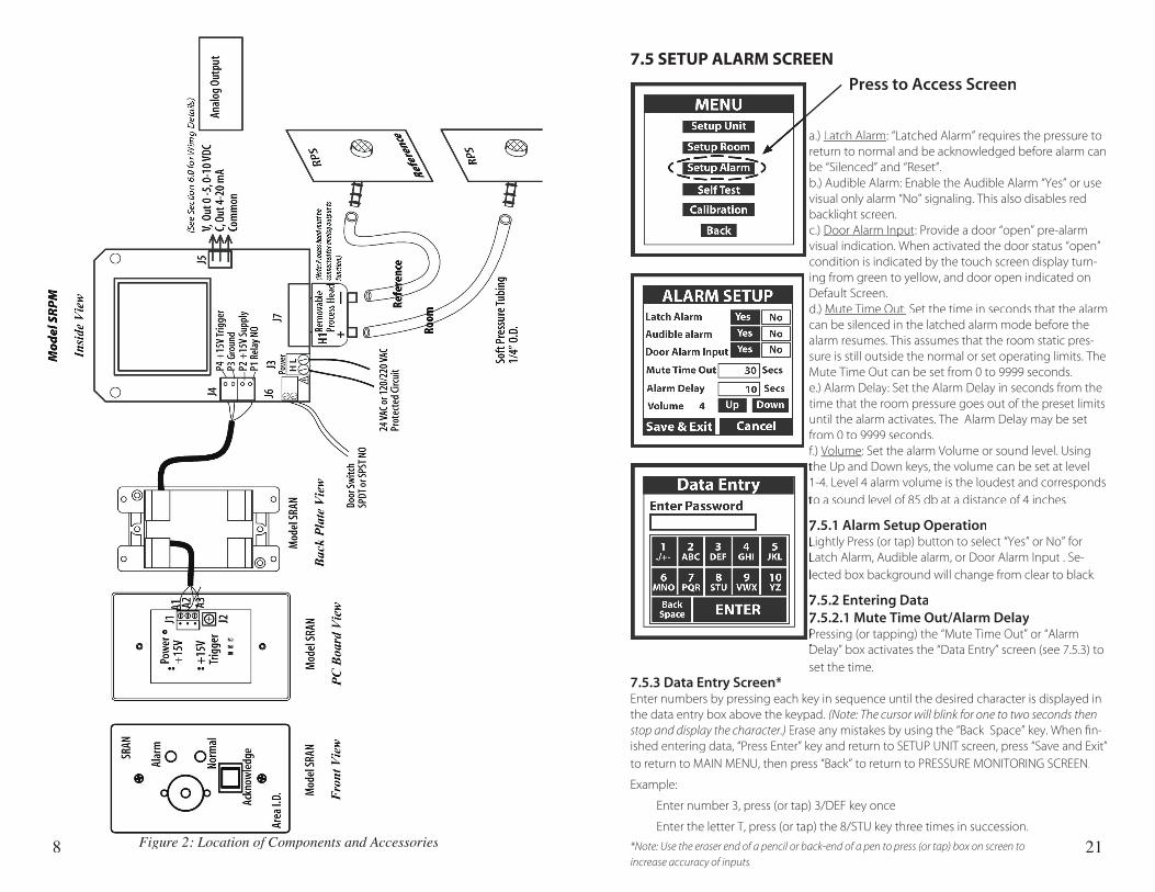
8 Figure 2: Location of Components and Accessories 21
7.5 SETUP ALARM SCREEN
7.5.3 Data Entry Screen*Enter numbers by pressing each key in sequence until the desired character is displayed in the data entry box above the keypad. (Note: The cursor will blink for one to two seconds then stop and display the character.) Erase any mistakes by using the “Back Space” key. When fi n-ished entering data, “Press Enter” key and return to SETUP UNIT screen, press “Save and Exit” to return to MAIN MENU, then press “Back” to return to PRESSURE MONITORING SCREEN.
Example:
Enter number 3, press (or tap) 3/DEF key once
Enter the letter T, press (or tap) the 8/STU key three times in succession.
*Note: Use the eraser end of a pencil or back-end of a pen to press (or tap) box on screen to
increase accuracy of inputs.
Press to Access Screen
a.) Latch Alarm: “Latched Alarm” requires the pressure to return to normal and be acknowledged before alarm can be “Silenced” and “Reset”. b.) Audible Alarm: Enable the Audible Alarm “Yes” or use visual only alarm “No” signaling. This also disables red backlight screen.c.) Door Alarm InputDoor Alarm Input: Provide a door “open” pre-alarm visual indication. When activated the door status “open” condition is indicated by the touch screen display turn-ing from green to yellow, and door open indicated on Default Screen.d.) Mute Time Out: Set the time in seconds that the alarm can be silenced in the latched alarm mode before the alarm resumes. This assumes that the room static pres-sure is still outside the normal or set operating limits. The Mute Time Out can be set from 0 to 9999 seconds.e.) Alarm DelayAlarm Delay: Set the Alarm Delay in seconds from the time that the room pressure goes out of the preset limits until the alarm activates. The Alarm Delay may be set from 0 to 9999 seconds.f.) Volume: Set the alarm Volume or sound level. Using the Up and Down keys, the volume can be set at level the Up and Down keys, the volume can be set at level 1-4. Level 4 alarm volume is the loudest and corresponds 1-4. Level 4 alarm volume is the loudest and corresponds to a sound level of 85 db at a distance of 4 inches.to a sound level of 85 db at a distance of 4 inches.
7.5.1 Alarm Setup Operation7.5.1 Alarm Setup OperationLightly Press (or tap) button to select “Yes” or No” for Lightly Press (or tap) button to select “Yes” or No” for Latch Alarm, Audible alarm, or Door Alarm Input . Se-Latch Alarm, Audible alarm, or Door Alarm Input . Se-lected box background will change from clear to black.lected box background will change from clear to black.
7.5.2 Entering Data7.5.2 Entering Data7.5.2.1 Mute Time Out/Alarm Delay7.5.2.1 Mute Time Out/Alarm DelayPressing (or tapping) the “Mute Time Out” or “Alarm Pressing (or tapping) the “Mute Time Out” or “Alarm Delay” box activates the “Data Entry” screen (see 7.5.3) to Delay” box activates the “Data Entry” screen (see 7.5.3) to set the time.
9
3.0 Mounting and Wiring
3.1 Mounting
For 120/240 VAC Version, onlyCAUTION: Do not open or remove SRPM cover (tool required) with input power applied unless performed by a licensed electrician. “Hazardous Live” voltage is present at connector J3 when power is applied. Please observe the warning
symbol ( ) near the J3 power connector.
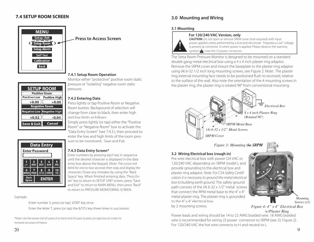
The Setra Room Pressure Monitor is designed to be mounted on a standard double gang metal electrical box using a 4 x 4 inch plaster ring adaptor. Remove the SRPM cover and mount the baseplate to the plaster ring adaptor using (4) 6-32 1/2 inch long mounting screws, see Figure 2. Note: The plaster ring external mounting face needs to be positioned fl ush to recessed, relative to the surface of the wall. Also note the orientation of the 4 mounting screws in the plaster ring, the plaster ring is rotated 90° from conventional mounting.
3.2 Wiring Electrical box (rough in)Pre-wire electrical box with power (24 VAC or 120/240 VAC depending on SRPM model ), and provide grounding to the electrical box and plaster ring adaptor. Note: For CSA Safety Certifi -cation it is necessary to ground the metal electrical box to building earth ground. The safety ground path consists of the (4) 6-32 x 1/2” metal screws that connect the RPM metal base to the 4” x 4” metal plaster ring. The plaster ring is grounded to the 4” x 4” electrical box by 2 mounting screws.
Electrical Box
4 x 4 inch Plaster Ring 4 x 4 inch Plaster Ring 4 x 4 inch Plaster Ring (Rotated 90°)(Rotated 90°)
SRPM Metal Base
SRPM Cover
Figure 4: 4” x 4” Electrical Box w/Plaster Ring
Power leads and wiring should be 14 to 22 AWG braided wire. 18 AWG braided wire is recommended for wiring J3 power connector to SRPM (see J3, Figure 2). For 120/240 VAC the hot wire connects to H and neutral to L.
Figure 3: Mounting the SRPM Figure 3: Mounting the SRPM Figure 3: Mounting the SRPM
!
symbol ( ) near the J3 power connector.
is present at connector J3 when power is applied. Please observe the warning
symbol ( ) near the J3 power connector.symbol ( ) near the J3 power connector.!
20
7.4.1 Setup Room OperationMonitor either “protective” positive room static pressure or “isolating” negative room static pressure.
7.4.2 Entering DataPress lightly or tap Positive Room or Negative Room button. Background of selection will change from clear to black, then enter high and low limits as follows:.Simply press lightly (or tap) either the “Positive Room” or “Negative Room” box to activate the “Data Entry Screen” (see 7.4.3.), then proceed to enter the low and high limits of the room pres-sure to be monitored. Save and Exit.
7.4.3 Data Entry Screen*Enter numbers by pressing each key in sequence until the desired character is displayed in the data entry box above the keypad. (Note: The cursor will blink for one to two seconds then stop and display the character.) Erase any mistakes by using the “Back Space” key. When fi nished entering data, “Press En-ter” key to return to SETUP UNIT screen, press “Save and Exit” to return to MAIN MENU, then press “Back” to return to PRESSURE MONITORING SCREEN.
7.4 SETUP ROOM SCREEN
Example:
Enter number 3, press (or tap) 3/DEF key once
Enter the letter T, press (or tap) the 8/STU key three times in succession.
*Note: Use the eraser end of a pencil or back-end of a pen to press (or tap) box on screen to
increase accuracy of inputs.. 20. 20
Press to Access Screen
Mounting Screws (x2)
(4) 6-32 x 1/2” Metal Screws
10
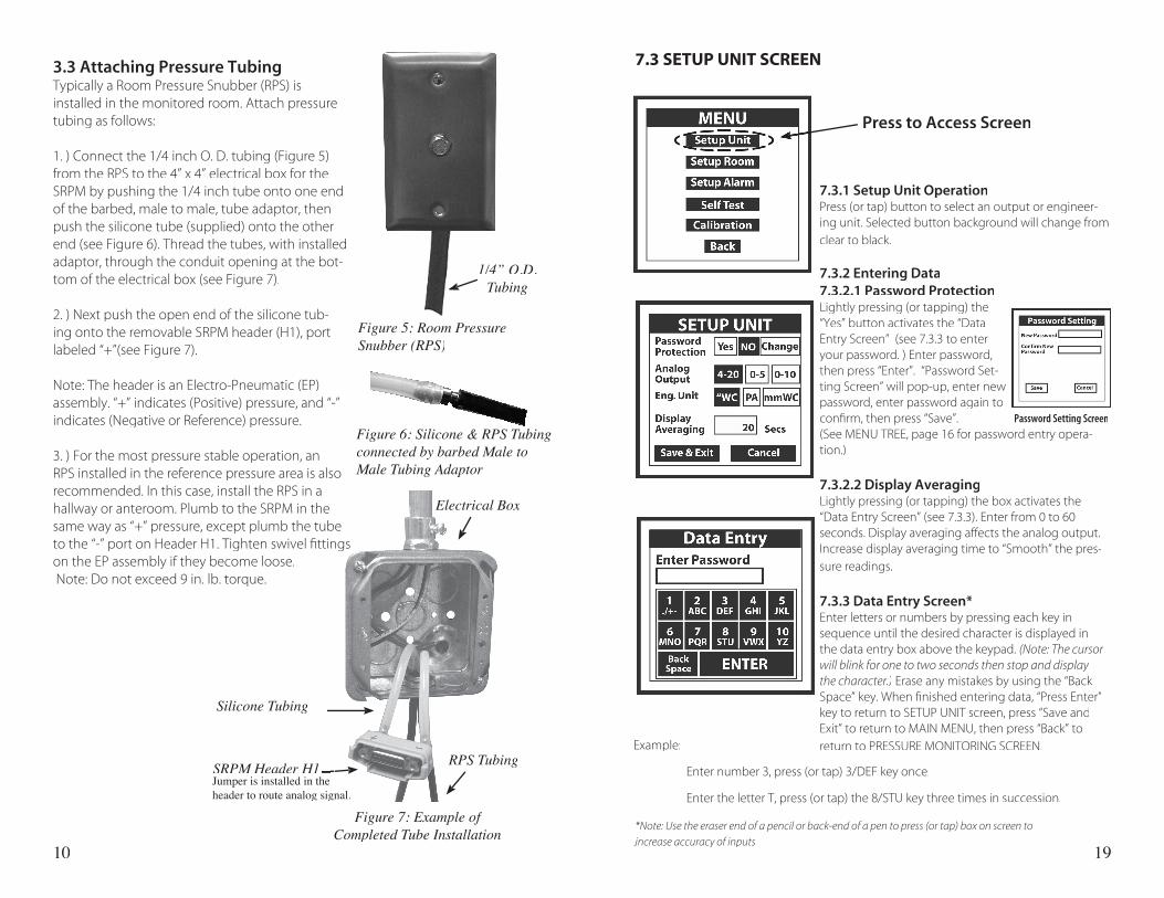
3.3 Attaching Pressure TubingTypically a Room Pressure Snubber (RPS) is installed in the monitored room. Attach pressure tubing as follows:
1. ) Connect the 1/4 inch O. D. tubing (Figure 5) from the RPS to the 4” x 4” electrical box for the SRPM by pushing the 1/4 inch tube onto one end of the barbed, male to male, tube adaptor, then push the silicone tube (supplied) onto the other end (see Figure 6). Thread the tubes, with installed adaptor, through the conduit opening at the bot-tom of the electrical box (see Figure 7).
2. ) Next push the open end of the silicone tub-ing onto the removable SRPM header (H1), port labeled “+”(see Figure 7).
Note: The header is an Electro-Pneumatic (EP) assembly. “+” indicates (Positive) pressure, and “-” indicates (Negative or Reference) pressure.
3. ) For the most pressure stable operation, an RPS installed in the reference pressure area is also recommended. In this case, install the RPS in a hallway or anteroom. Plumb to the SRPM in the same way as “+” pressure, except plumb the tube to the “-” port on Header H1. Tighten swivel fi ttings on the EP assembly if they become loose. Note: Do not exceed 9 in. lb. torque.
Figure 5: Room Pressure Snubber (RPS)
1/4” O.D. Tubing
Electrical Box
Silicone Tubing
RPS TubingSRPM Header H1
Figure 6: Silicone & RPS Tubing connected by barbed Male to Male Tubing Adaptor
Figure 7: Example of Completed Tube Installation
19
7.3.1 Setup Unit OperationPress (or tap) button to select an output or engineer-ing unit. Selected button background will change from clear to black.
7.3.2 Entering Data7.3.2.1 Password ProtectionLightly pressing (or tapping) the “Yes” button activates the “Data Entry Screen” (see 7.3.3 to enter your password. ) Enter password, then press “Enter”. “Password Set-ting Screen” will pop-up, enter new password, enter password again to confi rm, then press “Save”. (See MENU TREE, page 16 for password entry opera-tion.)
7.3.2.2 Display AveragingLightly pressing (or tapping) the box activates the “Data Entry Screen” (see 7.3.3). Enter from 0 to 60 seconds. Display averaging affects the analog output. Increase display averaging time to “Smooth” the pres-sure readings.
7.3.3 Data Entry Screen*Enter letters or numbers by pressing each key in sequence until the desired character is displayed in the data entry box above the keypad. (Note: The cursor will blink for one to two seconds then stop and display the character.) Erase any mistakes by using the “Back Space” key. When fi nished entering data, “Press Enter” key to return to SETUP UNIT screen, press “Save andExit” to return to MAIN MENU, then press “Back” to return to PRESSURE MONITORING SCREEN.
7.3 SETUP UNIT SCREEN
Press to Access Screen
Example:
Enter number 3, press (or tap) 3/DEF key once.
Enter the letter T, press (or tap) the 8/STU key three times in succession.
. *Note: Use the eraser end of a pencil or back-end of a pen to press (or tap) box on screen to
increase accuracy of inputs. increase accuracy of inputs. .
SRPM Header H1
Password Setting Screen
Jumper is installed in the header to route analog signal.
11
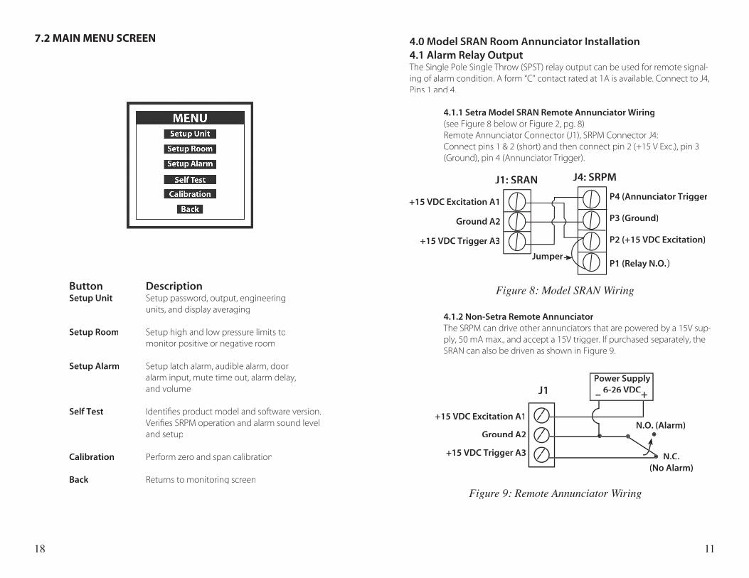
4.0 Model SRAN Room Annunciator Installation4.1 Alarm Relay OutputThe Single Pole Single Throw (SPST) relay output can be used for remote signal-ing of alarm condition. A form “C” contact rated at 1A is available. Connect to J4, Pins 1 and 4.
4.1.1 Setra Model SRAN Remote Annunciator Wiring (see Figure 8 below or Figure 2, pg. 8) Remote Annunciator Connector (J1), SRPM Connector J4: Connect pins 1 & 2 (short) and then connect pin 2 (+15 V Exc.), pin 3
(Ground), pin 4 (Annunciator Trigger).
4.1.2 Non-Setra Remote Annunciator The SRPM can drive other annunciators that are powered by a 15V sup-
ply, 50 mA max., and accept a 15V trigger. If purchased separately, the SRAN can also be driven as shown in Figure 9.
+15 VDC Excitation A1
Ground A2
+15 VDC Trigger A3 N.C. (No Alarm)
N.O. (Alarm)
J1
Jumper
P4 (Annunciator Trigger
P3 (Ground)
P2 (+15 VDC Excitation)
P1 (Relay N.O.)
+15 VDC Excitation A1
Ground A2
+15 VDC Trigger A3
J1: SRAN J4: SRPM
Power Supply6-26 VDC– +6-26 VDC– +6-26 VDC
Figure 9: Remote Annunciator Wiring
18
Button DescriptionSetup Unit Setup password, output, engineering units, and display averaging
Setup Room Setup high and low pressure limits to monitor positive or negative room
Setup Alarm Setup latch alarm, audible alarm, door alarm input, mute time out, alarm delay, and volume
Self Test Identifi es product model and software version. Verifi es SRPM operation and alarm sound level and setup
Calibration Perform zero and span calibration
Back Returns to monitoring screenBack Returns to monitoring screenBack
7.2 MAIN MENU SCREEN
Figure 8: Model SRAN Wiring
12
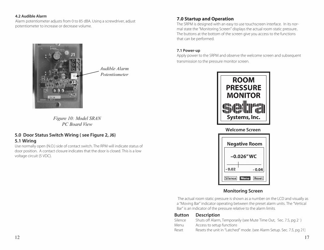
4.2 Audible AlarmAlarm potentiometer adjusts from 0 to 85 dBA. Using a screwdriver, adjust potentiometer to increase or decrease volume.
Audible Alarm Potentiometer
5.0 Door Status Switch Wiring ( see Figure 2, J6)5.1 WiringUse normally open (N.O.) side of contact switch. The RPM will indicate status of door position. A contact closure indicates that the door is closed. This is a low voltage circuit (5 VDC).
17
7.0 Startup and OperationThe SRPM is designed with an easy to use touchscreen interface. In its nor-mal state the “Monitoring Screen” displays the actual room static pressure.. The buttons at the bottom of the screen give you access to the functions that can be performed.
7.1 Power-upApply power to the SRPM and observe the welcome screen and subsequent
transmission to the pressure monitor screen.
Button DescriptionSilence Shuts off Alarm, Temporarily (see Mute Time Out, Sec. 7.5, pg 21)Menu Access to setup functionsReset Resets the unit in “Latched” mode. (see Alarm Setup. Sec. 7.5, pg 21)
Welcome Screen
Monitoring Screen
The actual room static pressure is shown as a number on the LCD and visually as a “Moving Bar” indicator operating between the preset alarm units. The “Vertical Bar” is an indicator of the pressure relative to the alarm limits.
Figure 10: Model SRAN PC Board View
J1
J2
13
Figure 11: Analog Output (J5)
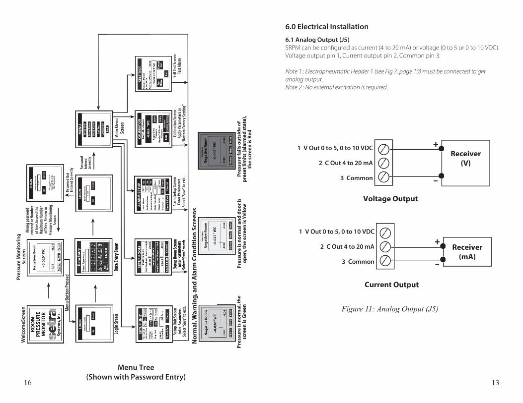
6.0 Electrical Installation
6.1 Analog Output (J5)SRPM can be confi gured as current (4 to 20 mA) or voltage (0 to 5 or 0 to 10 VDC). Voltage output pin 1, Current output pin 2, Common pin 3.
Note 1.: Electropneumatic Header 1 (see Fig 7, page 10) must be connected to get analog output. Note 2.: No external excitation is required.
16
Menu Tree(Shown with Password Entry)
Pre
ssu
re M
on
ito
rin
gSc
reen
Wel
com
eScr
een
Mai
n M
enu
Scre
enDa
ta En
try S
reen
Pass
wor
dEn
tere
dCo
rrec
tly
No
rmal
, Wa
No
rmal
, Wa
No
rmal
,rn
ing
, an
d A
larm
Co
nd
itio
n S
cree
ns
Pre
ssu
re is
no
rmal
, th
eP
ress
ure
is n
orm
al, t
he
Pre
ssu
re is
no
rmal
,sc
reen
is G
reen
Pre
ssu
re is
no
rmal
an
d d
oo
r is
op
en, t
he
scre
en is
o
pen
, th
e sc
reen
is
op
en,
Yell
oYe
llo
Yw
Pre
ssu
re f
alls
ou
tsid
e o
fp
rese
t li
mit
s (a
larm
ed s
tate
),th
e sc
reen
is R
ed
Setu
p Un
it Sc
reen
Ente
r Par
amet
ers
Sele
ct “S
ave”
to e
xit.
Setu
p Ro
om S
cree
nEn
ter P
aram
eter
sSSe
lec
elec
t t “S“S
ave
ave”
” to
exit
to e
xit.
Alar
m S
etup
Scr
een
Ente
r Par
amet
ers
Sele
ct “S
ave”
to e
xit.
Calib
ratio
n Sc
reen
Appl
y Par
amet
ers o
r“R
esto
re Fa
ctor
y Set
ting”.
Self
Test
Scr
een
Test
Scr
een
TTe
st A
larm
Test
Ala
rmT
LOG
INEn
ter
Pas
swo
rd
OK
Can
cel
Usr
!
Wro
ng
Pas
swo
rdEn
tere
d, R
e-en
ted
, Re-
ente
d,
rth
e P
assw
ord
LOG
INEn
ter
Pas
swo
rd
OK
Can
cel
LOG
INEn
ter
Pas
swo
rd
OK
Can
cel
Use
r!
MEN
US
etu
p U
nit
Set
up
Ro
om
Set
up
Ala
rm
Sel
f Tes
t
Cal
ibra
tio
n
Bac
k
MEN
UC
ALI
BR
AT
ION
Neg
ativ
e R
oo
m
Ap
ply
Zer
oP
ress
ure
Ap
ply
Fu
ll S
cale
Pre
ssu
re
-0.0
26
“W
C ZER
O
SPA
N
Res
tore
Fact
ory
Set
tin
gEx
it
Pass
wor
d No
tEn
tere
d Co
rrec
tly
Neg
ativ
e R
oo
m
–0.0
21
” W
C
-0.0
2-0
.04
Sil
ence
Men
uR
eset
Do
or
Op
en
Neg
ativ
e R
oo
m
–0.0
01
”W
C
-0.0
2-0
.04
Sil
ence
Men
uR
eset
Do
or
Op
en
Wro
ng p
assw
ord
ente
red
or N
umbe
rof
Trie
s Exc
eed
the
Max
imum
Num
ber
of Tr
ies.
Retu
rn to
Pres
sure
Mon
itorin
gSc
reen
MEN
UA
LAR
M S
ETU
PLa
tch
Ala
rm
Au
dib
le a
larm
Do
or
Ala
rm In
pu
t
Yes
Yes
Yes
No
No
No
Mu
te T
ime
Ou
tS
ecs
Ala
rm D
elay
Sec
s
Vo
lum
e
V
olu
me
V4
Ca
nce
lS
av
e &
Ex
it
Up
Do
wn
30 10
Logi
n Sr
een
Men
u Bu
tton
Pre
ssed
1 V Out 0 to 5, 0 to 10 VDC
2 C Out 4 to 20 mA
3 Common
●●●●
●●●●
Receiver(V)
+
–
1 V Out 0 to 5, 0 to 10 VDC
2 C Out 4 to 20 mA
3 Common
●●●●
●●●●
Receiver(mA)
+
–
Voltage Output
Current Output
14 15
User’s Operating Instructions


