
1A_Ch6(1)
1A_Ch6(2)
6.1 Basic Geometric Knowledge
A Points, Lines and Planes
B Angles
C Parallel and Perpendicular
Lines
Index

1A_Ch6(3)
6.2 Plane Figures
A Circles
B Triangles
C Polygons
Index
• Introduction toPlane Figures
1A_Ch6(4)
6.3 Three-dimensional Figures
A Introduction
B Sketch the Two-dimensional
(2-D) Representation of Simple
Solids
Index

1A_Ch6(5)
6.4 Polyhedra
A Introduction to Polyhedra
B Making Models of Polyhedra
Index
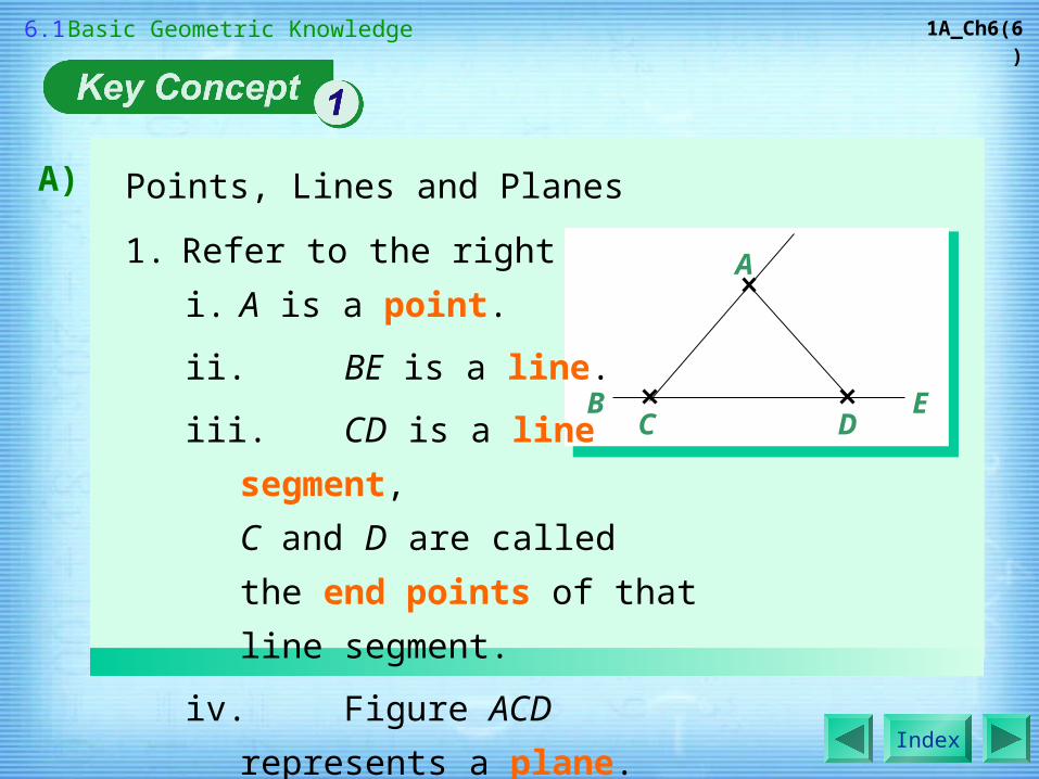
Points, Lines and Planes
1. Refer to the right figure.
Index
A)
1A_Ch6(6)
A
C DEB
i. A is a point.
ii. BE is a line.
iii. CD is a line segment,
C and D are called
the end points of that line segment.
iv. Figure ACD represents a plane.
6.1 Basic Geometric Knowledge

Points, Lines and Planes
2. Relations among Points, Lines and Planes
i. The straight line in the common part of
two planes is called the line of intersection.
ii. The two lines meet each other at a
point, that point is called the point of
intersection.
Index
A)
1A_Ch6(7)
linepoint of intersection
line
6.1 Basic Geometric Knowledge
Example
Index 6.1

(a) Name all the line segments and
planes in the given figure.
(b) Which point is the point of
intersection of MQ and PN ?
(a) Line segments :
Index
1A_Ch6(8)
M
N
P
Q
O
MN, MO, NO, OP, OQ, PQ, MQ, NP
Planes : MNO, OPQ
6.1 Basic Geometric Knowledge
(b) Point of intersection of MQ and PN : O Key Concept 6.1.1

Types of Angles
Angles can be classified according to their ‘sizes’ as follows:
Index
B)
1A_Ch6(9)
• Note : In a figure, a right angle is usually indicated by the symbol
‘ ’ but not an arc ‘ ’.
Acuteangle
Rightangle
Obtuseangle
Straightangle
Reflexangle
Roundangle
6.1 Basic Geometric Knowledge
Example
Index 6.1

What kind of angle is each of the following
angles in the given figure?
(a) ∠AOB (b) ∠BOD
(a) ∠AOB = 180°
Index
1A_Ch6(10)
A
O
B
C
D
140°
180 °
∴ ∠AOB is a straight angle.
(b) ∠BOD = ∠BOC – ∠COD
= 140° – 90°
= 50°
∴ ∠BOD is an acute angle.
6.1 Basic Geometric Knowledge

Index
1A_Ch6(11)
What kind of angle is each of the
following angles in the given figure?
(a) ∠AFE (b) ∠AHD (c) ∠EFB
(a) ∠AFE = 120°
∴ ∠AFE is an obtuse angle.
(b) ∠AHD = 90°
∴ ∠AHD is a right angle.
(c) ∠EFB = ∠EFA + ∠AFB
= 120° + 60°
= 180°
∴ ∠EFB is a straight angle.
Fulfill Exercise Objective
Classify an angle.
6.1 Basic Geometric Knowledge
Key Concept 6.1.2

Parallel and Perpendicular Lines
i. RS and TU are a pair of parallel
lines. We can write RS // TU.
ii. AB and TU are a pair of
perpendicular lines. We can
write AB ⊥ TU.
Index
C)
1A_Ch6(12)
R
S
T
U
BA
iii. Parallel and perpendicular lines can be constructed by
a ruler and a set square.
6.1 Basic Geometric Knowledge
Example
Index 6.1

Name all the parallel lines and
perpendicular lines in the given
figure.
Index
1A_Ch6(13)
Parallel lines : AG // DC // FE, GF // DE
Perpendicular lines : AB ⊥ BC, AG ⊥ GF, GF ⊥ FE, FE
⊥ ED, ED ⊥ DC
6.1 Basic Geometric Knowledge
Key Concept 6.1.3
A
G
D
F
E
C
B

Introduction to Plane Figures
1. A geometric figure formed by points, lines and planes
lying in the same plane is called a plane figure.
Index
1A_Ch6(14)
E.g.
Circle Triangle Polygon
6.2 Plane Figures
Index 6.2

1. O is the centre.
2. OP is the radius.
3. AOB is the diameter.
4. The curve AQBPA which forms the entire circle isthe circumference.
5. The curve AP is part of the circumference, called an arc of the circle.
6. Circles and arcs can be constructed by a pair of compasses.
Index
1A_Ch6(15)
OA B
P
Q
A) Circles
6.2 Plane Figures

Note :
i. ‘Circumference’, ‘radius’ and ‘diameter’ can
represent lengths as well.
ii. Diameter = 2 × radius
Index
1A_Ch6(16)
arc
diameter
radius
A) Circles
6.2 Plane Figures
Example
Index 6.2

It is known that O is the centre of each of the following circles,
find the values of the unknowns.
(a) (b)
Index
1A_Ch6(17)
x cm 12 cmO
O
y m
4.5 m
(a) Diameter = 12 cm
∴ x = 12 ÷ 2
= 6
(b) Radius = 4.5 m
∴ y = 4.5 × 2
= 9
6.2 Plane Figures
Key Concept 6.2.2

1. In the above triangle,
Index
1A_Ch6(18)
B) TrianglesA
BC
2. The sum of the three angles of a triangle is 180°.
i. the line segments AB, BC and CA are called the
sides of △ABC,
ii. points A, B, C are called the vertices (singular :
vertex) of △ABC.
6.2 Plane Figures
Example

3. Classification of triangles :
Index
1A_Ch6(19)
B) Triangles
Acute-angled triangle
Right-angled triangle
Obtuse-angled triangle
6.2 Plane Figures

3. Classification of triangles :
Index
1A_Ch6(20)
B) Triangles
Scalene triangle
Isosceles triangle
Equilateraltriangle
6.2 Plane Figures
Example

4. Triangles can be constructed by a protractor and a pair
of compasses etc. according to given conditions:
i. Given three sides of a triangle.
ii. Given two sides and the included angle of a
triangle.
Index
1A_Ch6(21)
B) Triangles
6.2 Plane Figures
Example
Index 6.2
Index
1A_Ch6(22)
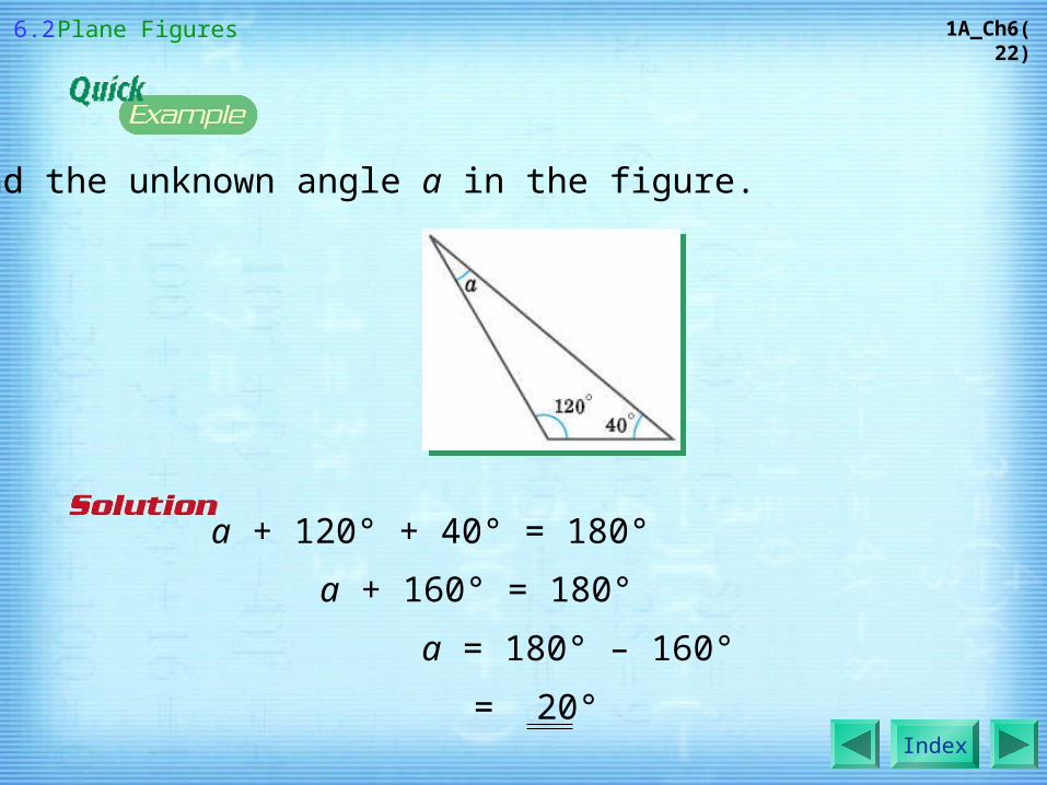
Find the unknown angle a in the figure.
a + 120° + 40° = 180°
a + 160° = 180°
a = 180° – 160°
= 20°
6.2 Plane Figures

Index
1A_Ch6(23)
Find the unknowns x and y in
△ABC as shown.
In △ABD,
x + 62° + 90° = 180°x + 152° = 180°
x = 180° – 152°= 28°
In △ABC,
28° + 62° + 48° + y = 180°138° + y = 180°
y = 180° – 138°= 42°
Fulfill Exercise Objective
Find an unknown angle in a triangle.
6.2 Plane Figures
Key Concept 6.2.3

For the above triangles A, B, C and D, identify
(a) scalene obtuse-angled triangle?
(b) isosceles acute-angled triangle?
Index
1A_Ch6(24)
(a) C
(b) D
A B C D
6.2 Plane Figures
Key Concept 6.2.4

Index
1A_Ch6(25)
Construct △ABC, where AB = 4 cm, BC = 3 cm and
AC = 3.5 cm.Steps :
1. Use a ruler to draw a line segment AB of 4 length cm.
2. With centre at A and radius 3.5 cm, use a pair of compasses to draw an arc.
3. With centre at B and radius 3 cm, use a pair of compasses to draw another arc.
4. The two arcs drawn should meet at C.
5. Join AC, then BC. △ABC is drawn.
Fulfill Exercise Objective
Construct a
triangle.
6.2 Plane Figures

Index
1A_Ch6(26)
Construct △PQR, where PQ = 3 cm, ∠RPQ = 50° and
RP = 4 cm.
Fulfill Exercise Objective
Construct a
triangle.
Steps :
1. Use a ruler to draw a line segment PQ of length 3 cm.
2. Use a protractor to draw ∠TPQ that measures 50°.
3. Use a ruler to mark a point R on PT produced such that RP = 4 cm.
4. Join QR, then △PQR is drawn.
6.2 Plane Figures
Key Concept 6.2.6

1. A plane figure formed by 3 or more line segments is
called a polygon.
2. A polygon is usually named by the number of its sides
or n-sided polygon (n is whole number).
Index
1A_Ch6(27)
C) Polygons
6.2 Plane Figures

Index
1A_Ch6(28)
3. The line segments that form a polygon are called sides of the polygon.
4. The point where two adjacent sides meet is called a vertex of the polygon.
5. The line segment joining two non-adjacent vertices is called a diagonal.
C) Polygons
diagonalvertex
side
6.2 Plane Figures

Index
1A_Ch6(29)
Classification of polygons :
C) Polygons
Equilateral polygon
Equiangular polygon
Regular polygon
6.2 Plane Figures
Index 6.2
Example

Index
1A_Ch6(30)
(a) A, C
(b) A, B
(c) A
For each of the following polygons, state whether it is
(a) an equilateral polygon; (b) an equiangular polygon;
(c) a regular polygon.
B CA
6.2 Plane Figures
Key Concept 6.2.8

Index
1A_Ch6(31)
1. A solid is an object that occupies space.
2. The surfaces of a solid are called faces.
3. The line segment on a solid that is formed by any two
intersecting faces is called an edge.
4. A point that is formed by 3 or more intersecting faces
on a solid is called a vertex.
A) Introduction
edge
face
vertex
6.3 Three-dimensional Figures
Index 6.3
Index
1A_Ch6(32)
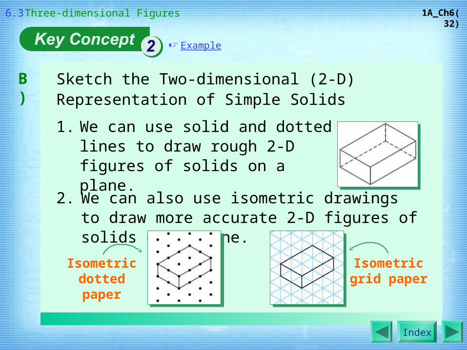
1. We can use solid and dotted lines to draw rough 2-D figures of solids on a plane.
B) Sketch the Two-dimensional (2-D) Representation of Simple Solids
2. We can also use isometric drawings to draw more accurate 2-D figures of solids on a plane.
Isometric dotted paper
Isometricgrid paper
6.3 Three-dimensional Figures
Example

Index
1A_Ch6(33)
B)
The face obtained by cutting a solid along a certain plane is called a cross-section of the solid. If we cut the solid at different positions, we may obtain different cross-sections.
Note : If we obtain the same cross-sections by cutting a solid along certain direction, then the cross-sections are called uniform cross-sections.
DifferentCross-sections
6.3 Three-dimensional Figures
Example
Index 6.3
Sketch the Two-dimensional (2-D) Representation of Simple Solids
Index
1A_Ch6(34)
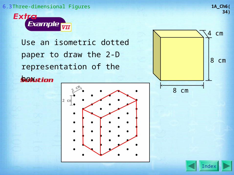
Use an isometric dotted paper to draw
the 2-D representation of the box.
8 cm
8 cm
4 cm
2 cm
2 cm
6.3 Three-dimensional Figures

Index
1A_Ch6(35)
Use an isometric grid paper to
draw the 2-D representation of
the given solid.
6 cm
6 cm
6 cm
4 cm
4 cm
2 cm
2 cm
6.3 Three-dimensional Figures
Key Concept 6.3.2

Index
1A_Ch6(36)
Which of the following faces represents the
cross-section of the given solid when it is
cut vertically along the blue line?
A B C
The cross-section is B.
6.3 Three-dimensional Figures

Index
1A_Ch6(37)
Draw the cross-section of the given
solid when it is cut horizontally along
the yellow line.
Fulfill Exercise Objective
Draw the cross-section of a simple solid.
The cross-section is :
6.3 Three-dimensional Figures
Key Concept 6.3.3

Index
1A_Ch6(38)
A) Introduction to Polyhedra
If all the faces of a solid are polygons, then that solid is
called a polyhedron.
Note : The polyhedra can be named by their numbers of faces.
6.4 Polyhedra
Example
Index 6.4

Index
1A_Ch6(39)
Determine which of the following solids is not a polyhedron.
A B C D
B
6.4 Polyhedra
Key Concept 6.4.1

Index
1A_Ch6(40)
B) Making Models of Polyhedra
We can use a net to make a model of polyhedron.
(a) (b)
For example, the net in Fig.(a) can be folded up to make a
model of the polyhedron in Fig.(b).
6.4 Polyhedra
Example
Index 6.4
Index
1A_Ch6(41)
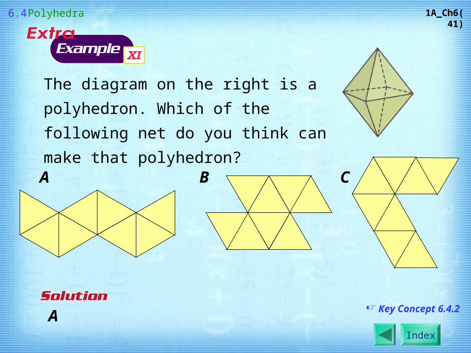
The diagram on the right is a polyhedron.
Which of the following net do you think can
make that polyhedron?
A
A B C
6.4 Polyhedra
Key Concept 6.4.2


