
Product Data SheetNovember 2013
00813-0100-4016, Rev NA
Rosemount DP Level Transmitters and 1199 Seal Systems
Applications
Level, Flow, Pressure, Interface, Density
Extreme hot and cold temperatures
Corrosive, clogging, or viscous processes
Hygienic requirements
Special process connections

Rosemount DP Level November 2013
2 www.rosemount.com
Proven, Reliable, and Innovative DP Level Technologies To meet your application requirements, Rosemount DP level technologies deliver an unsurpassed product offering that is easy to specify, order, and install. The offering includes a wide variety of process connections, direct mount or capillary connections, and materials of construction to address almost any application. If you don’t see what you need listed here, ask us. We can create a custom engineered solution to meet your needs.
Rosemount Level Transmitters
Level transmitters combine world-class Rosemount pressure instrumentation with direct-mount seals, all in a single integrated model number.
Rosemount 3051SAL, 3051L, and 2051L Level Transmitters
Achieve best-in-class system reliability with All-Welded systems
Wireless configurations provide new data access
Connect to virtually any process with a comprehensive offering of process connections, fill fluids, direct mount or capillary connections, and materials
Quantify and optimize total system performance with QZ option
Rosemount Tuned-System™ Assemblies optimize results
Reduce installed costs by 20% by eliminating excess capillary and transmitter mounting hardware
Improve performance by up to 30%
Increase response time by up to 80%
Reduce risk with up-front quantified performance reports
Rosemount 3051S Electronic Remote Sensor Systems
The Rosemount 3051S ERS System is a new digital DP Level architecture that links two 3051S pressure sensors together electronically. Differential pressure, level, and volume is calculated and transmitted using a standard two-wire 4-20 mA HART signal.
A Digital Upgrade to a Proven Technology
90% improvement in time response
Elimination of temperature effects and measurement drift
MultiVariable capabilities including DP, PLO, PHI, Volume, and Level
Proven Rosemount 3051S sensor technology
Simplified Installations and Maintenance Routines
Elimination of wet legs or dry legs
Easy installations without need for heat tracing and insulation
Proactive maintenance and troubleshooting with sensor alerts and diagnostics
Simplified inventories with sensors and standard cable
Balanced System Tuned-System Assembly
Two equal lengthsof capillary
Direct mount plus capillary

Rosemount DP LevelNovember 2013
3www.rosemount.com
Rosemount 1199 Seal SystemsA seal system consists of a pressure transmitter, one or two seals, a fill fluid, and either a direct mount or capillary style connection. Seal systems provide a reliable process pressure measurement and prevent the process medium from contacting the transmitter diaphragm. Transmitter/diaphragm seal systems should be considered when:
The process temperature is outside of the operating ranges of the transmitter.
The process is corrosive and/ or requires specific exotic materials of construction.
The process contains suspended solids or is viscous and is prone to plugging of connections.
The application requires the use of flush-mount hygienic connections that facilitates CIP/SIP service.
There is a requirement for easier cleaning of the process from the connections to avoid contamination between batches.
Application Flexibility
Flanged, threaded, and hygienic process connections
Meets industry standards such as EN 1092-1, ANSI/ASME B16.5, JIS B2238, ANSI/ASME B1.20.1, EN 10226-1, GOST 12815-80, China Chemical Industrial Standards HG20615 and HG20592, and 3-A Standard 74-03
Variety of fill fluids including cold temperature (-102 °F / -75 °C), hot temperature (698 °F / 370 °C), and hygienic & food grade
Three different capillary diameters allow for optimization of accuracy and time response
Reliable System Construction
Welded design with no threaded connections
100% Helium leak tested
Advanced manufacturing techniques ensure air-free, leak-tight system that is stable over time
Reliable operation in full vacuum applications
Robust Seal Design
Backup convolutions on the diaphragm protect seal integrity
Recessed diaphragms reduce potential for handling damage
Contents
Ordering Information
Rosemount 3051S ERS System . . . . . . . . . . . . . . . . . page 4Rosemount 3051S Scalable Level Transmitter . .page 17Rosemount 3051L Level Transmitter . . . . . . . . . page 35Rosemount 2051L Level Transmitter . . . . . . . . . page 42Rosemount 1199 Direct Mount Seal Systems . page 48Rosemount 1199 Remote Mount Seal Systems . page 54
Flanged Seals . . . . . . . . . . . . . . . . . . . . . . . . . . . . . . . . . . page 61
Threaded Seals . . . . . . . . . . . . . . . . . . . . . . . . . . . . . . . . page 79
Hygienic seals . . . . . . . . . . . . . . . . . . . . . . . . . . . . . . . . . page 83
Specialty Seals . . . . . . . . . . . . . . . . . . . . . . . . . . . . . . . . . page 94
Specifications . . . . . . . . . . . . . . . . . . . . . . . . . . . . . . . . . page 101
Product Certifications . . . . . . . . . . . . . . . . . . . . . . . . . . . page 114
Dimensional drawings . . . . . . . . . . . . . . . . . . . . . . . . page 130

Rosemount DP Level November 2013
Rosemount 3051S Electronic Remote Sensor System
The 3051S ERS™ System is a flexible, 2-wire 4-20 mA HART architecture that calculates differential pressure (DP) electronically using two pressure sensors that are linked together with a non-proprietary electrical wire.
Ideal applications for the 3051S ERS System include tall vessels and distillation columns that have traditionally required long lengths of capillary or impulse piping. When used in these types of applications, the 3051S ERS System can deliver:
More accurate and repeatable DP measurements
Faster time response
Simplified installations
Reduced maintenance
How to order
1. Choose two 3051S ERS transmitter models. These may be any combination of 3051SAM and 3051SAL models.
2. Decide which model will be the ERS Primary (4-20 mA loop termination and optional LCD) and which will be the ERS Secondary. This will be specified by the “Configuration Type” code in each model number.
3. Specify two full model numbers per the desired configuration.
Additional InformationSpecifications: page 101Certifications: page 119Dimensional Drawings: page 130
Rosemount 3051SAM Transmitter for ERS Applications
Coplanar and In-Line sensor module platforms
Variety of process connections including threaded NPT, flanges, manifolds, and 1199 remote seals
Available with 10-year stability and limited 12-year warranty
Table 1. 3051SAM Transmitter for ERS Applications Ordering Information★ The Standard offering represents the most common models and options. The starred options (★) should be selected for best delivery.__The Expanded offering is subject to additional delivery lead time.
Model Transmitter Type
3051SAM Scalable Advanced Measurement Transmitter
Performance Class(1)
Standard Standard
1 Ultra: 0.025% span accuracy, 200:1 rangedown, 10-year stability, 12-year limited warranty ★
2 Classic: 0.035% span accuracy, 150:1 rangedown, 5-year stability ★
Secondary
Primary
3051SAM
Coplanar In-Line
Coplanar In-Line
3051SAL
1
2
3 3051SAL1PG4AA1A1020DFF71DA00M53051SAM1ST2A2E11A2A
4 www.rosemount.com

Rosemount DP LevelNovember 2013
5www.rosemount.com
Configuration Type
Standard Standard
P Electronic Remote Sensor - Primary ★
S Electronic Remote Sensor - Secondary ★
Pressure Module Type Pressure Sensor Type
Standard Standard
G Coplanar Gage ★
T In-Line Gage ★
E In-Line Absolute ★
Expanded
A Coplanar Absolute
Pressure Range(2)
Coplanar Gage In-Line Gage In-Line Absolute Coplanar Absolute
Standard Standard
1A N/A-14.7 to 30 psig(-1,0 to 2,06 bar)
0 to 30 psia (0 to 2,06 bar)
0 to 30 psia (0 to 2,06 bar)
★
2A-250 to 250 inH2O(-623 to 623 mbar)
-14.7 to 150 psig(-1,0 to 10,34 bar)
0 to 150 psia (0 to 10,34 bar)
0 to 150 psia (0 to 10,34 bar)
★
3A-393 to 1000 inH2O(-0,98 to 2,49 bar)
-14.7 to 800 psig(-1,0 to 55,2 bar)
0 to 800 psia (0 to 55,2 bar)
0 to 800 psia (0 to 55,2 bar)
★
4A-14.2 to 300 psig(-0,98 to 20,7 bar)
-14.7 to 4000 psig(-1,0 to 275,8 bar)
0 to 4000 psia (0 to 275,8 bar)
0 to 4000 psia (0 to 275,8 bar)
★
5A-14.2 to 2000 psig(-0,98 to 137,9 bar)
-14.7 to 10000 psig(-1,0 to 689,5 bar)
0 to 10000 psia(0 to 689,5 bar)
N/A ★
Isolating Diaphragm
Standard Standard
2(3) 316L SST ★
3(3) Alloy C-276 ★
Expanded
4(4) Alloy 4005(4)(5) Tantalum 6(4) Gold-plated Alloy 400 (includes Graphite-Filled PTFE O-Ring)7(4) Gold-plated 316L SST
Process Connection
Coplanar Module Type In-Line Module Type
Standard Standard
000 None N/A ★
A11(6) Assemble to Rosemount 305 Manifold Assemble to Rosemount 306 Manifold ★
A12(6) Assemble to Rosemount 304 or AMF Manifold with SST Traditional Flange
N/A ★
B11(6)(7) Assemble to One Rosemount 1199 Remote Seal with SST transmitter flange
Assemble to One Rosemount 1199 Remote Seal ★
E11 Coplanar Flange (CS), ¼-18 NPT, 316 SST Drain Vents ½ -14 NPT Female ★
E12 Coplanar Flange (SST), ¼-18 NPT, 316 SST Drain Vents N/A ★
E13(3) Coplanar Flange (Cast C-276), ¼-18 NPT, Alloy C-276 Drain Vents
N/A ★
Table 1. 3051SAM Transmitter for ERS Applications Ordering Information★ The Standard offering represents the most common models and options. The starred options (★) should be selected for best delivery.__The Expanded offering is subject to additional delivery lead time.

Rosemount DP Level November 2013
6 www.rosemount.com
Standard Standard
E14Coplanar Flange (Cast Alloy 400), ¼-18 NPT, Alloy 400/K-500 Drain Vents
N/A ★
E15(3) Coplanar Flange (SST), ¼-18 NPT, Alloy C-276 Drain Vents
N/A ★
E16(3) Coplanar Flange (CS), ¼-18 NPT, Alloy C-276 Drain Vents
N/A ★
E21 Coplanar Flange (CS), RC ¼, 316 SST Drain Vents N/A ★
E22 Coplanar Flange (SST), RC ¼, 316 SST Drain Vents N/A ★
E23(3) Coplanar Flange (Cast C-276), RC ¼, Alloy C-276 Drain Vents
N/A ★
E24Coplanar Flange (Cast Alloy 400), RC ¼, alloy 400/K-500 Drain Vents
N/A ★
E25(3) Coplanar Flange (SST), RC ¼, Alloy C-276 Drain Vents N/A ★
E26(3) Coplanar Flange (CS), RC ¼, Alloy C-276 Drain Vents N/A ★
F12Traditional Flange (SST), 1/4-18 NPT, 316 SST Drain Vents
N/A ★
F13(3) Traditional Flange (Cast C-276), 1/4-18 NPT, Alloy C-276 Drain Vents
N/A ★
F14Traditional Flange (Cast Alloy 400), 1/4-18 NPT, Alloy 400/K-500 Drain Vents
N/A ★
F15(3) Traditional Flange (SST), 1/4-18 NPT, Alloy C-276 Drain Vents
N/A ★
F22 Traditional Flange (SST), RC ¼, 316 SST Drain Vents N/A ★
F23(3) Traditional Flange (Cast C-276), RC ¼, Alloy C-276 Drain Vents
N/A ★
F24Traditional Flange (Cast Alloy 400), RC ¼, Alloy 400/K500 Drain Vents
N/A ★
F25(3) Traditional Flange (SST), RC ¼, Alloy C-276 Drain Vents N/A ★
F52DIN-Compliant Traditional Flange (SST), ¼-18 NPT, 316 Drain Vents, 7-16-in. Bolting
N/A ★
G11Vertical Mount Level Flange (SST), 2-in ANSI Class 150, 316 SST Drain Vents
G ½ A DIN 16288 Male (Range 1-4 Only) ★
G12Vertical Mount Level Flange (SST), 2-in ANSI Class 300, 316 SST Drain Vents
N/A ★
G21Vertical Mount Level Flange (SST), 3-in ANSI Class 150, 316 SST Drain Vents
N/A ★
G22Vertical Mount Level Flange (SST), 3-in ANSI Class 300, 316 SST Drain Vents
N/A ★
G31Vertical Mount Level Flange (SST), DIN-DN 50 PN 40, 316 SST Drain Vents
N/A ★
G41Vertical Mount Level Flange (SST), DIN-DN 80 PN 40, 316 SST Drain Vents
N/A ★
Expanded
F11Traditional Flange (CS), ¼-18 NPT, 316 SST Drain / Vents
Non-Threaded Instrument Flange (I-Flange) (Range 1-4 only)
F32Bottom Vent Traditional Flange (SST), ¼-18 NPT, 316 SST Drain Vents
N/A
F42Bottom Vent Traditional Flange (SST), RC ¼, 316 SST Drain Vents
N/A
F62DIN-Compliant Traditional Flange (316 SST), ¼-18 NPT, 316 Drain Vents, M10 Bolting
N/A
F72DIN-Compliant Traditional Flange (316 SST), ¼-18 NPT, 316 Drain Vents, M12 Bolting
N/A
Table 1. 3051SAM Transmitter for ERS Applications Ordering Information★ The Standard offering represents the most common models and options. The starred options (★) should be selected for best delivery.__The Expanded offering is subject to additional delivery lead time.

Rosemount DP LevelNovember 2013
Transmitter Output
Standard Standard
A 4–20 mA with digital signal based on HART protocol ★
Housing Style Material Conduit Entry Size
Standard Standard
Housings for ERS Primary - Configuration Type code P1A PlantWeb Housing Aluminum 1/2–14 NPT ★
1B PlantWeb Housing Aluminum M20 x 1.5 (CM 20) ★
1J PlantWeb Housing SST 1/2–14 NPT ★
1K PlantWeb Housing SST M20 x 1.5 (CM 20) ★
2E Junction Box with Remote Display Output Aluminum 1/2–14 NPT ★
2F Junction Box with Remote Display Output Aluminum M20 x 1.5 (CM 20) ★
2M Junction Box with Remote Display Output SST 1/2–14 NPT ★
Standard Standard
Housings for ERS Secondary - Configuration Type code S2A Junction Box Aluminum 1/2–14 NPT ★
2B Junction Box Aluminum M20 x 1.5 (CM 20) ★
2J Junction Box SST 1/2–14 NPT ★
Expanded
Housings for ERS Primary - Configuration Type code P1C PlantWeb Housing Aluminum G1/2
1L PlantWeb Housing SST G1/2
2G Junction Box with Remote Display Output Aluminum G1/2
Housings for ERS Secondary - Configuration Type code S2C Junction Box Aluminum G1/2
Options (Include with selected model number)
Electronic Remote Sensor Connection Cable
Standard Standard
R05 50 ft. (15.2 m) Spool of Electronic Remote Sensor Cable ★
R10 100 ft. (30.5 m) Spool of Electronic Remote Sensor Cable ★
R15 150 ft. (45.7m) Spool of Electronic Remote Sensor Cable ★
Mounting Bracket
Standard Standard
B1(4) Traditional flange bracket, CS, 2-in. pipe ★
B2(4) Traditional flange bracket, CS, panel ★
B3(4) Traditional flange flat bracket, CS, 2-in. pipe ★
B4 Bracket, all SST, 2-in. Pipe and Panel ★
B7(4) Traditional flange bracket, B1 with SST bolts ★
B8(4) Traditional flange bracket, B2 with SST bolts ★
B9(4) Traditional flange bracket, B3 with SST bolts ★
BA(4) Traditional flange bracket, B1, all SST ★
BC(4) Traditional flange bracket, B3, all SST ★
Table 1. 3051SAM Transmitter for ERS Applications Ordering Information★ The Standard offering represents the most common models and options. The starred options (★) should be selected for best delivery.__The Expanded offering is subject to additional delivery lead time.
7www.rosemount.com

Rosemount DP Level November 2013
Special Configuration (Software)
Standard Standard
C1(8) Customer Software Configuration (“Configuration Data Sheet” Must Be Completed) ★
C3 Gage Pressure Calibration on Rosemount 3051SAM_ _A4 only ★
C4(8) NAMUR Alarm and Saturation Levels, High Alarm ★
C5(8) NAMUR Alarm and Saturation Levels, Low Alarm ★
C6(8) Custom Alarm and Saturation Levels, High Alarm (Requires C1 and Configuration Data Sheet) ★
C7(8) Custom Alarm and Saturation Levels, Low Alarm (Requires C1 and Configuration Data Sheet) ★
C8(8) Low alarm (standard Rosemount alarm and saturation levels) ★
Special Configuration (Hardware)
Standard Standard
D2(9) 1/2-14 NPT Flange Adapters ★
D4 External ground screw assembly ★
D5(9) Delete transmitter drain/vent valves (install plugs) ★
Expanded
D7(9) Coplanar flange without drain/vent portsD9(9) RC 1/2 Flange Adapters
Product Certifications
Standard Standard
E1 ATEX Flameproof ★
I1 ATEX Intrinsic Safety ★
N1 ATEX Type n ★
K1 ATEX Flameproof and Intrinsically Safe, Type n, Dust ★
ND ATEX Dust ★
E4 TIIS Flameproof ★
E5 FM Explosion-proof, Dust Ignition-proof ★
I5 FM Intrinsically Safe, Division 2 ★
K5 FM Explosion-proof, Dust Ignition-proof, Intrinsically Safe, Division 2 ★
E6(10) CSA Explosion-proof, Dust Ignition-proof, Division 2 ★
I6 CSA Intrinsically Safe ★
K6(10) CSA Explosion-proof, Dust Ignition-proof, Intrinsically Safe, Division 2 ★
E7 IECEx Flameproof ★
I7 IECEx Intrinsic Safety ★
N7 IECEx Type n ★
K7 IECEx Flameproof, Intrinsic Safety, Type n ★
E2 INMETRO Flameproof ★
I2 INMETRO Intrinsically Safe ★
K2 INMETRO Flameproof, Intrinsic Safety, Type n ★
E3 China Flameproof ★
I3 China Intrinsic Safety, Dust Ignition-proof ★
KA(10) ATEX and CSA Flameproof, Intrinsically Safe, Division 2 ★
KB(10) FM and CSA Explosion-proof, Dust Ignition-proof, Intrinsically Safe, Division 2 ★
KC FM and ATEX Explosion-proof, Intrinsically Safe, Division 2 ★
KD(10) FM, CSA, and ATEX Explosion-proof, Intrinsically Safe ★
Table 1. 3051SAM Transmitter for ERS Applications Ordering Information★ The Standard offering represents the most common models and options. The starred options (★) should be selected for best delivery.__The Expanded offering is subject to additional delivery lead time.
8 www.rosemount.com

Rosemount DP LevelNovember 2013
Special Certifications
Standard Standard
Q4 Calibration Certificate ★
QP Calibration Certificate and Tamper Evident Seal ★
Material Traceability Certification
Standard Standard
Q8 Material Traceability Certification per EN 10204 3.1 ★
Quality Certification for Safety
Standard Standard
QS Prior-use Certificate of FMEDA Data ★
Surface Finish Certification
Standard Standard
Q16(11) Surface Finish Certification for Hygienic Remote Seals ★
Toolkit Performance Reports
Standard Standard
QZ(12) Remote Seal System Performance Calculation Report ★
Terminal Blocks
Standard Standard
T1(8) Transient Terminal Block ★
Sensor Fill Fluid
Standard Standard
L1(13) Inert Sensor Fill Fluid ★
O-Ring
Standard Standard
L2 Graphite-Filled PTFE O-Ring ★
Bolting Material
Standard Standard
L4(9) Austenitic 316 SST Bolts ★
L5(3)(9) ASTM A 193, Grade B7M Bolts ★
L6(9) Alloy K-500 Bolts ★
L7(3)(9) ASTM A 453, Class D, Grade 660 Bolts ★
L8(9) ASTM A 193, Class 2, Grade B8M Bolts ★
Display Type (ERS Primary Only)
Standard Standard
M5(8) PlantWeb LCD Display ★
M7(8) Remote Mount LCD Display and Interface, PlantWeb Housing, No Cable, SST Bracket ★
M8(8) Remote Mount LCD Display and Interface, PlantWeb Housing, 50 ft. (15.2 m) Cable, SST Bracket ★
M9(8) Remote Mount LCD Display and Interface, PlantWeb Housing, 100 ft. (30.5 m) Cable, SST Bracket ★
Special Procedures
Expanded
P1 Hydrostatic Testing with Certificate
Table 1. 3051SAM Transmitter for ERS Applications Ordering Information★ The Standard offering represents the most common models and options. The starred options (★) should be selected for best delivery.__The Expanded offering is subject to additional delivery lead time.
9www.rosemount.com

Rosemount DP Level November 2013
10 www.rosemount.com
Special Cleaning
Expanded
P2(9) Cleaning for Special ServicesP3(9) Cleaning for Less than 1 PPM Chlorine/Fluorine
NACE Certificate
Standard Standard
Q15(14) Certificate of Compliance to NACE MRO175/ISO 15156 for wetted materials ★
Q25(14) Certificate of Compliance to NACE MRO103 for wetted materials ★
Typical Model Number: 3051SAM 1 S T 2A 2 E11 A 2A
(1) For the 3051SAM with B11 “Assemble to” code for 1199 Remote Seals, use ±0.55% of span for Ultra and ±0.65% of span for Classic performance.
(2) The pressure range should be specified based on the maximum static pressure, not differential pressure.
(3) Materials of Construction comply with metallurgical requirements highlighted within NACE MR 0175 / ISO 15156 for sour oil field production environments. Environmental limits apply to certain materials. Consult latest standard for details. Selected materials also conform to NACE MR 0103 for sour refining environments.
(4) Not available with Pressure Sensor / Module codes T or E.
(5) Tantalum diaphragm material is only available with Pressure Sensor / Module code G.
(6) “Assemble to” items are specified separately and require a completed model number.
(7) Consult an Emerson Process Management representative for performance specifications.
(8) Not available with Configuration Type code S.
(9) Not available with Process Connection code A11.
(10) Not available with M20 or G ½ conduit entry size.
(11) Q16 is only available when the diaphragm seal has surface finish options.
(12) The QZ report quantifies the performance of the entire ERS system. One report is provided per ERS system. The QZ option is specified on the Primary Transmitter (Configuration Type code P).
(13) Silicone fill fluid is standard.
(14) NACE wetted compliant materials are identified by footnote (3).
Table 1. 3051SAM Transmitter for ERS Applications Ordering Information★ The Standard offering represents the most common models and options. The starred options (★) should be selected for best delivery.__The Expanded offering is subject to additional delivery lead time.

Rosemount DP LevelNovember 2013
ndard
★
★
ndard
★
★
ndard
★
★
★
ndard
★
★
★
★
★
11www.rosemount.com
Rosemount 3051SAL Transmitter for ERS Applications
Integrated transmitter and remote seal in a single model number
Variety of process connections including flanged, threaded, and hygienic remote seals
Available with 10-year stability and limited 12-year warranty
A 3051SAL Transmitter consists of 3 parts. First, specify the transmitter model codes found on page 11. Then, specify a remote seal found on page 25. Finish the model number by specifying all desired options on page 14.
Table 2. Rosemount 3051SAL Transmitter for ERS Applications Ordering Information★ The Standard offering represents the most common models and options. These options should be selected for best delivery.__The Expanded offering is subject to additional delivery lead time.
Model Transmitter Type
3051SAL Scalable Advanced Level Transmitter
Performance Class
Standard Sta
1 Ultra: 0.055% span accuracy, 150:1 rangedown, 12-year limited warranty
2 Classic: 0.065% span accuracy, 150:1 rangedown
Configuration Type
Standard Sta
P Electronic Remote Sensor - Primary
S Electronic Remote Sensor - Secondary
Pressure Module Type Pressure Sensor Type
Standard Sta
G Coplanar Gage
T In-Line Gage
E In-Line Absolute
Expanded
A Coplanar Absolute
Pressure Range(5)
Coplanar Gage In-Line Gage In-Line Absolute Coplanar Absolute
Standard Sta
1A N/A-14.7 to 30 psig(-1,0 to 2,06 bar)
0 to 30 psia (0 to 2,06 bar)
0 to 30 psia (0 to 2,06 bar)
2A-250 to 250 inH2O(-623 to 623 mbar)
-14.7 to 150 psig(-1,0 to 10,34 bar)
0 to 150 psia (0 to 10,34 bar)
0 to 150 psia (0 to 10,34 bar)
3A-393 to 1000 inH2O(-0,98 to 2,49 bar)
-14.7 to 800 psig(-1,0 to 55,2 bar)
0 to 800 psia (0 to 55,2 bar)
0 to 800 psia (0 to 55,2 bar)
4A-14.2 to 300 psig(-0,98 to 20,7 bar)
-14.7 to 4000 psig(-1,0 to 275,8 bar)
0 to 4000 psia (0 to 275,8 bar)
0 to 4000 psia (0 to 275,8 bar)
5A-14.2 to 2000 psig(-0,98 to 137,9 bar)
-14.7 to 10000 psig(-1,0 to 689,5 bar)
0 to 10000 psia(0 to 689 bar)
N/A
ERS Transmitter Model Codes_______page 11 Direct Mount Seal Model Codes_______page 25 ERS Options___________page 14

Rosemount DP Level November 2013
ndard
★
ndard
★
★
★
★
★
★
★
★
★
★
ndard
★
ndard
★
★
★
★
ndard
★
★
★
Transmitter Output
Standard Sta
A 4-20 mA with Digital Signal Based on HART Protocol
Housing Style Material Conduit Entry Size
Standard Sta
Housings for ERS Primary - Configuration Type code P
1A PlantWeb Housing Aluminum 1/2–14 NPT
1B PlantWeb Housing Aluminum M20 x 1.5 (CM 20)
1J PlantWeb Housing SST 1/2–14 NPT
1K PlantWeb Housing SST M20 x 1.5 (CM 20)
2E Junction Box with Remote Display Output Aluminum 1/2–14 NPT
2F Junction Box with Remote Display Output Aluminum M20 x 1.5 (CM 20)
2M Junction Box with Remote Display Output SST 1/2–14 NPT
Housings for ERS Secondary - Configuration Type code S
2A Junction Box Aluminum 1/2–14 NPT
2B Junction Box Aluminum M20 x 1.5 (CM 20)
2J Junction Box SST 1/2–14 NPT
Expanded
Housings for ERS Primary - Configuration Type code P
1C PlantWeb Housing Aluminum G1/2
1L PlantWeb Housing SST G1/2
2G Junction Box with Remote Display Output Aluminum G1/2
Housings for ERS Secondary - Configuration Type code S
2C Junction Box Aluminum G1/2
Seal System Type
Standard Sta
1 Direct-Mount Seal System
Direct-Mount Extension (Between Transmitter Flange and Seal)
Standard Sta
0 No Extension
2 2-in. (50 mm) Extension
4 4-in. (100 mm) Extension
5 Thermal Optimizer
Transmitter Reference Pressure Connection
Standard Sta
00 None (In-Line Style Sensor)
20 316L SST Isolator / SST Transmitter Flange
30 Alloy C-276 Isolator / SST Transmitter Flange
Table 2. Rosemount 3051SAL Transmitter for ERS Applications Ordering Information★ The Standard offering represents the most common models and options. These options should be selected for best delivery.__The Expanded offering is subject to additional delivery lead time.
12 www.rosemount.com

Rosemount DP LevelNovember 2013
ndard
★
★
★
★
★
★
★
★
13www.rosemount.com
Continue specifying a completed model number by choosing a remote seal type below:
Seal Fill FluidSpecific Gravity at 77 °F (25 °C)
Temperature Limits(1)
No Extension2-in. (50 mm) Extension
4-in. (100 mm) Extension
Thermal Optimizer
Standard Sta
D Silicone 200 0.93-49 to 401 °F (-45 to 205 °C)
-49 to 401 °F (-45 to 205 °C)
-49 to 401 °F (-45 to 205 °C)
-49 to 401 °F (-45 to 205 °C)
C Silicone 704 1.0732 to 401 °F(2)
(0 to 205 °C)32 to 464 °F(2) (0 to 240 °C)
32 to 500 °F(2)
(0 to 260 °C)32 to 599 °F (0 to 315 °C)
V Silicone 705 1.0968 to 401 °F(2) (20 to 205 °C)
68 to 464 °F(2) (20 to 240 °C)
68 to 500 °F(2) (20 to 260 °C)
68 to 698 °F(2) (20 to 370 °C)
A Syltherm XLT 0.85-102 to 293 °F (-75 to 145 °C)
-102 to 293 °F (-75 to 145 °C)
-102 to 293 °F (-75 to 145 °C)
-102 to 293 °F (-75 to 145 °C)
H Inert (Halocarbon) 1.85-49 to 320 °F (-45 to 160 °C)
-49 to 320 °F (-45 to 160 °C)
-49 to 320 °F (-45 to 160 °C)
-49 to 320 °F (-45 to 160 °C)
G(3)(4) Glycerin and Water 1.135 to 203 °F (-15 to 95 °C)
5 to 203 °F (-15 to 95 °C)
5 to 203 °F (-15 to 95 °C)
5 to 203 °F (-15 to 95 °C)
N(3) Neobee M-20 0.925 to 401 °F(2)
(-15 to 205 °C)5 to 437 °F (-15 to 225 °C)
5 to 437 °F (-15 to 225 °C)
5 to 437 °F (-15 to 225 °C)
P(3)(4) Propylene Glycol and Water
1.025 to 203 °F (-15 to 95 °C)
5 to 203 °F (-15 to 95 °C)
5 to 203 °F (-15 to 95 °C)
5 to 203 °F (-15 to 95 °C)
page 25 FF Flush Flanged SealProcess Connections:2 in. / DN 50 / 50A3 in. / DN 80 / 80A4 in. / DN 100 / 100A
page 27 EF Extended Flanged SealProcess Connections:3 in. / DN 80 / 80A4 in. / DN 100 / 100A
page 28 RF Remote Flanged SealProcess Connections:1 in. / DN 25 / 25A1.5 in. / DN 40 / 40A
page 30 RT Remote Threaded Seal
Process Connections:¼ - 18 NPT½ - 14 NPT¾ - 14 NPT1 – 11.5 NPT
page 32 SC Hygienic Tri-Clamp Seal
Process Connections:1.5 in.2 in.3 in.
page 33 SS Hygienic Tank Spud SealProcess Connections:4 in.
Table 2. Rosemount 3051SAL Transmitter for ERS Applications Ordering Information★ The Standard offering represents the most common models and options. These options should be selected for best delivery.__The Expanded offering is subject to additional delivery lead time.

Rosemount DP Level November 2013
14 www.rosemount.com
Options (Include with selected model number)(1)(2) (3) (4)
Electronic Remote Sensor Connection Cable
Standard(5) Standard
R05 50 ft. (15.2 m) Spool of Electronic Remote Sensor Cable ★
R10 100 ft. (30.5 m) Spool of Electronic Remote Sensor Cable ★
R15 150ft. (45.7m) Spool of Electronic Remote Sensor Cable ★
Software Configuration
Standard Standard
C1(6) Custom Software Configuration (Requires Configuration Data Sheet) ★
Gage Pressure Calibration
Standard Standard
C3 Gage Pressure Calibration on Rosemount 3051SAL_ _A4 only ★
Alarm Limit
Standard Standard
C4(6) NAMUR Alarm and Saturation Levels, High Alarm ★
C5(6) NAMUR Alarm and Saturation Levels, Low Alarm ★
C6(6) Custom Alarm and Saturation Levels, High Alarm (Requires C1 and Configuration Data Sheet) ★
C7(6) Custom Alarm and Saturation Levels, Low Alarm (Requires C1 and Configuration Data Sheet) ★
C8(6) Low Alarm (Standard Rosemount Alarm and Saturation Levels) ★
Ground Screw
Standard Standard
D4 External Ground Screw Assembly ★
Conduit Plug
Standard Standard
DO 316 SST Conduit Plug ★
Product Certifications
Standard Standard
E1 ATEX Flameproof ★
I1 ATEX Intrinsic Safety ★
N1 ATEX Type n ★
K1 ATEX Flameproof and Intrinsically Safe, Type n, Dust ★
ND ATEX Dust ★
E4 TIIS Flameproof ★
E5 FM Explosion-proof, Dust Ignition-proof ★
I5 FM Intrinsically Safe, Division 2 ★
K5 FM Explosion-proof, Dust Ignition-proof, Intrinsically Safe, Division 2 ★
E6(7) CSA Explosion-proof, Dust Ignition-proof, Division 2 ★
I6 CSA Intrinsically Safe ★
K6(7) CSA Explosion-proof, Dust Ignition-proof, Intrinsically Safe, Division 2 ★
E7 IECEx Flameproof ★
I7 IECEx Intrinsic Safety ★
N7 IECEx Type n ★
K7 IECEx Flameproof, Intrinsic Safety, Type n ★
E2 INMETRO Flameproof ★
I2 INMETRO Intrinsically Safe ★
K2 INMETRO Flameproof, Intrinsic Safety, Type n ★
KA(7) ATEX and CSA Flameproof, Intrinsically Safe, Division 2 ★
KB(7) FM and CSA Explosion-proof, Dust Ignition-proof, Intrinsically Safe, Division 2 ★
KC FM and ATEX Explosion-proof, Intrinsically Safe, Division 2 ★
KD(7) FM, CSA, and ATEX Explosion-proof, Intrinsically Safe ★

Rosemount DP LevelNovember 2013
Sensor Fill Fluid
Standard Standard
L1(8) Inert Sensor Fill Fluid ★
O-Ring
Standard Standard
L2 Graphite-filled PTFE O-ring ★
Bolting Material
Standard Standard
L4 Austenitic 316 SST Bolts ★
L5(9) ASTM A 193, Grade B7M Bolts ★
L6 Alloy K-500 Bolts ★
L7(9) ASTM A 453, Class D, Grade 660 Bolts ★
L8 ASTM A 193, Class 2, Grade B8M Bolts ★
Display Type (ERS Primary Only)
Standard Standard
M5(6) PlantWeb LCD Display ★
M7(6) Remote Mount LCD Display and Interface, PlantWeb Housing, No Cable, SST Bracket ★
M8(6) Remote Mount LCD Display and Interface, PlantWeb Housing, 50 ft. (15.2 m) Cable, SST Bracket ★
M9(6) Remote Mount LCD Display and Interface, PlantWeb Housing, 100 ft. (30.5 m) Cable, SST Bracket ★
Special Procedures
Pressure Testing
Expanded
P1 Hydrostatic Testing with Certificate
Special Cleaning
Expanded
P2 Cleaning for Special ServicesP3 Cleaning for Less than 1 PPM Chlorine/Fluorine
Special Certifications
Calibration Certification
Standard Standard
Q4 Calibration Certificate ★
QP Calibration certificate with tamper evident seal ★
Material Traceability Certification
Standard Standard
Q8 Material traceability certification per EN 10204 3.1 ★
Quality Certification for Safety
Standard Standard
QS Prior-use certificate of FMEDA Data ★
Toolkit Performance Reports
Standard Standard
QZ(10) Remote Seal System Performance Calculation Report ★
Transient Protection
Standard Standard
T1(6) Transient Terminal Block ★
15www.rosemount.com

Rosemount DP Level November 2013
NACE Certificate
Standard Standard
Q15(9) Certificate of Compliance to NACE MRO175/ISO 15156 for wetted materials ★
Q25(9) Certificate of Compliance to NACE MRO103 for wetted materials ★
Typical Model Number: 3051SAL 1 P G 4A A 1A 1 0 20 D FF 7 1 DA 0 0 M5
(1) At ambient pressure of 14.7 psia (1 bar-a) and ambient temperature of 70 °F (21 °C). Temperature limits are reduced in vacuum service and may be limited by seal selection.
(2) Maximum process temperature is limited by heat transfer to the transmitter electronics and must be further derated if ambient, temperature exceeds 70 °F (21 °C).
(3) This is a food grade fill fluid.
(4) Not suitable for vacuum applications.
(5) The pressure range should be specified based on the maximum static pressure, not differential pressure.
(6) Not available with Configuration Type code S.
(7) Not available with M20 or G ½ conduit entry size.
(8) Silicone fill fluid is standard.
(9) Materials of construction comply with metallurgical requirements highlighted within NACE MR 0175 / ISO 15156 for sour oil field production environments. Environmental limits apply to certain materials. Consult latest standard for details. Selected materials also conform to NACE MR 0103 for sour refining environments.
(10) The QZ report quantifies the performance of the entire ERS system. One report is provided per ERS system. The QZ option is specified on the Primary Transmitter (Configuration Type code P).
16 www.rosemount.com

Rosemount DP LevelNovember 2013
ard
ard
ard
17www.rosemount.com
Rosemount 3051S Scalable Level Transmitter
Rosemount 3051S Scalable Level Transmitters combine the features and benefits of a high-performance 3051S pressure transmitter with the durability and reliability of a direct mount seal all in a single model number.
Level transmitters can also be ordered with an additional 1199 Remote Mount Seal to form a Tuned-System Assembly that offers improved performance and reduced costs compared to traditional symmetrical (balanced) assemblies.
Product features and capabilities include:
Variety of process connections including flanged, threaded, and hygienic seals
Quantified performance for the entire transmitter / seal assembly (QZ option)
HART, FOUNDATION fieldbus, and Wireless protocols
Additional InformationSpecifications: page 114Dimensional Drawings: page 130
Rosemount 3051SAL Scalable Level Transmitter
A 3051SAL Scalable Level Transmitter consists of 3 parts. First, specify the transmitter model codes found on page 17. Then, specify a remote seal found on page 25. Finish the model number by specifying all desired options on page 20.
Tuned-System Assembly Comprised of 3051SAL with 1199 Flanged Seal
3051SAL Coplanar with “SS” Hygienic Tank Spud Seal
3051SAL In-Line with “FF” Flanged Seal
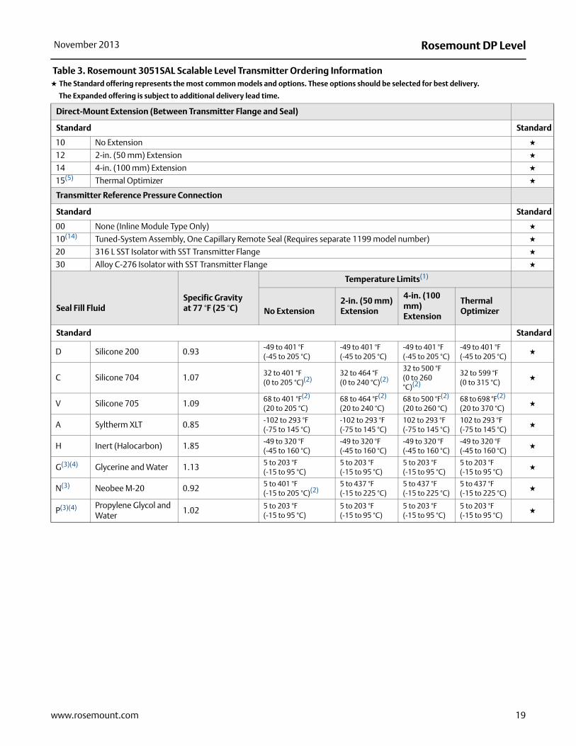
Table 3. Rosemount 3051SAL Scalable Level Transmitter Ordering Information★ The Standard offering represents the most common models and options. These options should be selected for best delivery.
__The Expanded offering is subject to additional delivery lead time.
Model Transmitter Type
3051SAL Scalable Level Transmitter
Performance Class
Standard Stand
1 Ultra: 0.055% span accuracy, 150:1 rangedown, 12-year limited warranty ★
2 Classic: 0.065% span accuracy, 150:1 rangedown ★
Configuration Type
Standard Stand
C Liquid Level Transmitter ★
Pressure Module Type Pressure Sensor Type
Standard Stand
D Coplanar Differential ★
G Coplanar Gage ★
T In-Line Gage ★
E In-Line Absolute ★
Expanded
A Coplanar Absolute
Transmitter Model Codes_.................._ page 17 Direct Mount Seal Model Codes_........._page 25 Transmitter Options......... page 20

Rosemount DP Level November 2013
ard
ard
ard
Pressure Range
Coplanar DP Coplanar Gage In-Line GageIn-Line Absolute
Coplanar Absolute
Standard Stand
1A N/A N/A-14.7 to 30 psig(-1,0 to 2,06 bar)
0 to 30 psia(0 to 2,06 bar)
0 to 30 psia(0 to 2,06 bar)
★
2A -250 to 250 inH2O(-623 to 623 mbar)
-250 to 250inH2O(-623 to 623 mbar)
-14.7 to 150 psig(-1,0 to 10,3 bar)
0 to 150 psia(0 to 10,34 bar)
0 to 150 psia(0 to 10,34 bar)
★
3A -1000 to 1000 inH2O(-2,5 to 2,5 bar)
-393 to 1000 inH2O(-0,98 to 2,5 bar)
-14.7 to 800 psig(-1,0 to 55,2 bar)
0 to 800 psia(0 to 55,2 bar)
0 to 800 psia(0 to 55,2 bar)
★
4A -300 to 300 psi(-20,7 to 20,7 bar)
-14.2 to 300 psig(-0,98 to 20,7 bar)
-14.7 to 4000 psig(-1,0 to 275,8 bar)
0 to 4000 psia(0 to 275,8 bar)
0 to 4000 psia(0 to 275,8 bar)
★
5A -2000 to 2000 psi(-137,9 to 137,9 bar)
-14.2 to 2000 psig(-0,98 to 137,9 bar)
-14.7 to 10000 psig(-1,0 to 689 bar)
0 to 10000 psia(0 to 689 bar)
N/A ★
Transmitter Output(2)
Standard Stand
A 4-20 mA with digital signal based on HART protocol ★
F(11) FOUNDATION fieldbus protocol ★
X(12) Wireless (Requires wireless options and wireless PlantWeb housing) ★
Housing Style Material(18) Conduit Entry
Standard Stand
1A PlantWeb housing Aluminum 1/2–14 NPT ★
1B PlantWeb housing Aluminum M20 x 1.5 ★
1J PlantWeb housing SST 1/2–14 NPT ★
1K PlantWeb housing SST M20 x 1.5 ★
2A Junction Box housing Aluminum 1/2–14 NPT ★
2B Junction Box housing Aluminum M20 x 1.5 ★
2EJunction Box with output for remote interface
Aluminum 1/2–14 NPT ★
2FJunction Box with output for remote interface
Aluminum M20 x 1.5 ★
2J Junction Box housing SST 1/2–14 NPT ★
5A(6) Wireless PlantWeb housing Aluminum 1/2–14 NPT ★
5J(6) Wireless PlantWeb housing SST 1/2–14 NPT ★
7J(13) Quick Connect (A size Mini, 4-pin male termination)
SST ★
Expanded
1C PlantWeb housing Aluminum G1/2
1L PlantWeb housing 316L SST G1/2
2C Junction Box housing Aluminum G1/2
2GJunction Box with output for remote interface
Aluminum G1/2
Table 3. Rosemount 3051SAL Scalable Level Transmitter Ordering Information★ The Standard offering represents the most common models and options. These options should be selected for best delivery.
__The Expanded offering is subject to additional delivery lead time.
18 www.rosemount.com
Rosemount DP LevelNovember 2013
ard
ard
ard
Direct-Mount Extension (Between Transmitter Flange and Seal)
Standard Stand
10 No Extension ★
12 2-in. (50 mm) Extension ★
14 4-in. (100 mm) Extension ★
15(5) Thermal Optimizer ★
Transmitter Reference Pressure Connection
Standard Stand
00 None (Inline Module Type Only) ★
10(14) Tuned-System Assembly, One Capillary Remote Seal (Requires separate 1199 model number) ★
20 316 L SST Isolator with SST Transmitter Flange ★
30 Alloy C-276 Isolator with SST Transmitter Flange ★
Seal Fill FluidSpecific Gravity at 77 °F (25 °C)
Temperature Limits(1)
No Extension2-in. (50 mm) Extension
4-in. (100 mm) Extension
Thermal Optimizer
Standard Stand
D Silicone 200 0.93 -49 to 401 °F (-45 to 205 °C)
-49 to 401 °F (-45 to 205 °C)
-49 to 401 °F (-45 to 205 °C)
-49 to 401 °F (-45 to 205 °C)
★
C Silicone 704 1.07 32 to 401 °F (0 to 205 °C)(2)
32 to 464 °F (0 to 240 °C)(2)
32 to 500 °F(0 to 260 °C)(2)
32 to 599 °F(0 to 315 °C)
★
V Silicone 705 1.09 68 to 401 °F(2) (20 to 205 °C)
68 to 464 °F(2) (20 to 240 °C)
68 to 500 °F(2) (20 to 260 °C)
68 to 698 °F(2) (20 to 370 °C)
★
A Syltherm XLT 0.85 -102 to 293 °F (-75 to 145 °C)
-102 to 293 °F (-75 to 145 °C)
102 to 293 °F(-75 to 145 °C)
102 to 293 °F(-75 to 145 °C)
★
H Inert (Halocarbon) 1.85 -49 to 320 °F(-45 to 160 °C)
-49 to 320 °F(-45 to 160 °C)
-49 to 320 °F(-45 to 160 °C)
-49 to 320 °F(-45 to 160 °C)
★
G(3)(4) Glycerine and Water 1.13 5 to 203 °F(-15 to 95 °C)
5 to 203 °F(-15 to 95 °C)
5 to 203 °F(-15 to 95 °C)
5 to 203 °F(-15 to 95 °C)
★
N(3) Neobee M-20 0.92 5 to 401 °F (-15 to 205 °C)(2)
5 to 437 °F(-15 to 225 °C)
5 to 437 °F (-15 to 225 °C)
5 to 437 °F(-15 to 225 °C)
★
P(3)(4) Propylene Glycol and Water
1.02 5 to 203 °F (-15 to 95 °C)
5 to 203 °F (-15 to 95 °C)
5 to 203 °F (-15 to 95 °C)
5 to 203 °F (-15 to 95 °C)
★
Table 3. Rosemount 3051SAL Scalable Level Transmitter Ordering Information★ The Standard offering represents the most common models and options. These options should be selected for best delivery.
__The Expanded offering is subject to additional delivery lead time.
19www.rosemount.com

Rosemount DP Level November 2013
20 www.rosemount.com
Continue specifying a completed model number by choosing a remote seal type below:
page 25FF Flush Flanged Seal
Process Connections:2 in. / DN 50 / 50A3 in. / DN 80 / 80A4 in. / DN 100 / 100A
page 27 EF Extended Flanged SealProcess Connections:3 in. / DN 80 / 80A4 in. / DN 100 / 100A
page 28 RF Remote Flanged SealProcess Connections:1 in. / DN 25 / 25A1.5 in. / DN 40 / 40A
page 30 RT Remote Threaded Seal
Process Connections:¼ - 18 NPT½ - 14 NPT¾ - 14 NPT1 – 11.5 NPT
page 32 SC Hygienic Tri-Clamp Seal
Process Connections:1.5 in.2 in.3 in.
page 33 SS Hygienic Tank Spud SealProcess Connections:4 in.
Wireless Options (Requires option code X and wireless PlantWeb housing)(1)(2) (3) (4)(5)
Update Rate
Standard(6) Standard
WA User Configurable Update Rate ★
Operating Frequency and Protocol
Standard(7) Standard
3 2.4 GHz DSSS, IEC 62591 (WirelessHART) ★
Omnidirectional Wireless Antenna
Standard(8) Standard
WK External Antenna ★
WM Extended Range, External Antenna ★
Expanded
WN High-Gain, Remote Antenna
SmartPower™
Standard(9) Standard
1(10) Adapter for Black Power Module (I.S. Power Module Sold Separately) ★
Other Options (Include with selected model number)
PlantWeb Control Functionality
Standard Standard
A01(11)(12) FOUNDATION fieldbus Advanced Control Function Block Suite ★
Hardware Adjustments
Standard Standard
D01(11)(12) FOUNDATION fieldbus Diagnostics Suite ★
DA2(13) Advanced HART Diagnostics Suite ★

Rosemount DP LevelNovember 2013
Software Configuration
Standard(14) Standard
C1(15) Custom software configuration (Requires Configuration Data Sheet) ★
Gage Pressure Calibration
Standard Standard
C3 Gage pressure calibration on Rosemount 3051SAL_ _A4 only ★
Alarm Limit
Standard Standard
C4(11)(15) NAMUR alarm and saturation levels, high alarm ★
C5(11)(15) NAMUR alarm and saturation levels, low alarm ★
C6(11)(15) Custom alarm and saturation signal levels, high alarm (Requires C1 and Configuration Data Sheet) ★
C7(11)(15) Custom alarm and saturation signal levels, low alarm (Requires C1 and Configuration Data Sheet) ★
C8(11)(15) Low alarm (standard Rosemount alarm and saturation levels) ★
Hardware Adjustments
Standard Standard
D1(11)(15)(16) Hardware adjustments (zero, span, alarm, security) ★
Flange Adapter
Standard Standard
D2 1/2-14 NPT flange adapter ★
Expanded
D9 RC 1/2 SST flange adapter ★
Ground Screw
Standard Standard
D4 External ground screw assembly ★
Drain/Vent Valve
Standard Standard
D5 Delete transmitter drain/vent valves (install plugs) ★
Conduit Plug
Standard Standard
DO(17) 316 SST Conduit Plug ★
Product Certifications(18)
Standard Standard
E1 ATEX Flameproof ★
I1 ATEX Intrinsic Safety ★
IA ATEX FISCO Intrinsic Safety (FOUNDATION fieldbus protocol only) ★
N1 ATEX Type n ★
K1 ATEX Flameproof, Intrinsic Safety, Type n, Dust ★
ND ATEX Dust ★
E4 TIIS Flameproof ★
E5 FM Explosion-proof, Dust Ignition-proof ★
I5 FM Intrinsically Safe, Division 2 ★
IE FM FISCO Intrinsically Safe (FOUNDATION fieldbus protocol only) ★
K5 FM Explosion-proof, Dust Ignition-proof, Intrinsically Safe, Division 2 ★
E6(19) CSA Explosion-proof, Dust Ignition-proof, Division 2 ★
I6 CSA Intrinsically Safe ★
IF CSA FISCO Intrinsically Safe (FOUNDATION fieldbus protocol only) ★
21www.rosemount.com

Rosemount DP Level November 2013
Standard Standard
K6(19) CSA Explosion-proof, Dust Ignition-proof, Intrinsically Safe, Division 2 ★
D3(20) Measurement Canada Accuracy Approval ★
E7 IECEx Flameproof, Dust Ignition-proof ★
I7 IECEx Intrinsic Safety ★
IG IECEx FISCO Intrinsic Safety (FOUNDATION fieldbus protocol only) ★
N7 IECEx Type n ★
K7 IECEx Flameproof, Dust Ignition-proof, Intrinsic Safety, Type n ★
E2 INMETRO Flameproof ★
I2 INMETRO Intrinsic Safety ★
K2 INMETRO Flameproof, Intrinsic Safety ★
E3 China Flameproof ★
I3 China Intrinsic Safety, Dust Ignition-proof ★
KA(19) ATEX and CSA Flameproof, Intrinsically Safe, Division 2 ★
KB(19) FM and CSA Explosion-proof, Dust Ignition-proof, Intrinsically Safe, Division 2 ★
KC FM and ATEX Explosion-proof, Intrinsically Safe, Division 2 ★
KD(19) FM, CSA, and ATEX Explosion-proof, Intrinsically Safe ★
Sensor Fill Fluid
Standard Standard
L1(21) Inert sensor fill fluid ★
O-Ring
Standard Standard
L2 Graphite-filled PTFE o-ring ★
Bolting Material
Standard Standard
L4 Austenitic 316 SST bolts ★
L5(22) ASTM A193, Grade B7M bolts ★
L6 Alloy K-500 bolts ★
L7(22) ASTM A453, Class D, Grade 660 bolts ★
L8 ASTM A193, Class 2, Grade B8M bolts ★
Display Type(23)
Standard Standard
M5 PlantWeb LCD Display ★
M7(11) Remote mount LCD display and interface, PlantWeb housing, no cable, SST bracket ★
M8(11) Remote mount LCD display and interface, PlantWeb housing, 50 ft. (15 m) cable, SST bracket ★
M9(11) Remote mount LCD display and interface, PlantWeb housing, 100 ft. (31 m) cable, SST bracket ★
Pressure Testing
Expanded
P1 Hydrostatic testing with certificate
Special Cleaning
Expanded
P2 Cleaning for special servicesP3 Cleaning for less than 1PPM Chlorine/Fluorine
Calibration Certification
Standard Standard
Q4 Calibration certificate ★
QP Calibration certificate and tamper evident seal ★
22 www.rosemount.com

Rosemount DP LevelNovember 2013
Material Traceability Certification
Standard Standard
Q8 Material traceability certification per EN 10204 3.1 ★
Quality Certification for Safety
Standard Standard
QS(11)(15) Prior-use certificate of FMEDA Data ★
QT(24) Safety-certified to IEC 61508 with certificate of FMEDA data ★
Toolkit Performance Reports
Standard Standard
QZ Remote Seal System Performance Calculation Report ★
Transient Protection
Standard Standard
T1(25)(26) Transient terminal block ★
Conduit Electrical Connector
Standard Standard
GE(27) M12, 4-pin, Male Connector (eurofast®) ★
GM(27) A size Mini, 4-pin, Male Connector (minifast®) ★
NACE Certificate
Standard Standard
Q15(22) Certificate of Compliance to NACE MRO175/ISO 15156 for wetted materials ★
Q25 Certificate of Compliance to NACE MRO103 for wetted materials ★
Typical Model Number: 3051SAL 1 C G 2A A 1A 10 20 D FF G 1 DA 0 0
(1) At ambient pressure of 14.7 psia (1 bar-a) and ambient temperature of 70 °F (21 °C). Temperature limits are reduced in vacuum service and may be limited by seal selection.
(2) Maximum process temperature is limited by heat transfer to the transmitter and must be further derated if ambient, temperature exceeds 70 °F (21 °C). See “” on page 107 for more information.
(3) This is a food grade fill fluid.
(4) Not suitable for vacuum applications.
(5) Only available with In-line style gage and absolute transmitters (Option codes T and E).
(6) Only available with output code X.
(7) Long-Life Power Module must be shipped separately, order Part #00753-9220-0001.
(8) Only available with output code X.
(9) Not available with output code A.
(10) Requires PlantWeb housing and Output code A. Includes Hardware Adjustments as standard.
(11) Requires PlantWeb housing.
(12) Available approvals are FM Intrinsically Safe, Division 2 (option code I5), CSA Intrinsically Safe (option code I6), ATEX Intrinsic Safety (option code I1), and IECEx Intrinsic Safety (option code I7).
(13) Available with output code A only. Available approvals are FM Intrinsically Safe, Division 2 (option code I5), ATEX Intrinsic Safety (option code I1), or IECEx Intrinsic Safety (option code I7). Contact an Emerson Process Management representative for additional information.
(14) With option code 10, user must select Seal Location option code M in Table 7 of Rosemount DP Level PDS.
(15) Not available with output code F.
23www.rosemount.com

Rosemount DP Level November 2013
(16) Transmitter is shipped with 316 SST conduit plug (uninstalled) in place of carbon steel conduit plug.
(17) Not available with housing style codes 2E, 2F, 2G, 2M, 5A, 5J, or 7J.
(18) Valid when SuperModule Platform and housing have equivalent approvals.
(19) Not available with M20 or G ½ conduit entry size.
(20) Requires PlantWeb housing and Hardware Adjustments option code D1. Limited availability depending on transmitter type and range. Contact an Emerson Process Management representative for additional information.
(21) Silicone fill fluid is standard.
(22) Materials of construction comply with metallurgical requirements highlighted within NACE MR0175 / ISO 15156 for sour oil field production environments. Environmental limits apply to certain materials. Consult latest standard for details. Selected materials also conform to NACE MR 0103 for sour refining environments.
(23) Not available with Housing code 01 or 7J.
(24) Not available with output code F or X. Not available with housing code 01 or 7J.
(25) Not available with Housing code 00, 01, 5A, or 7J.
(26) The T1 option is not needed with FISCO Product Certifications; transient protection is included in the FISCO product certification codes IA, IE, IF, and IG.
(27) Not available with Housing code 00, 01, 5A, or 7J. Available with Intrinsically Safe approvals only. For FM Intrinsically Safe, Division 2 (option code I5) or FM FISCO Intrinsically Safe (option code IE), install in accordance with Rosemount drawing 03151-1009 to maintain outdoor rating (NEMA 4X and IP66).
24 www.rosemount.com

Rosemount DP LevelNovember 2013
25www.rosemount.com
Direct Mount Seals for 3051SAL
Flush Flanged (FF) Seal
Most common seal
Good for use in general applications
Easy installation on flanged connections ranging from 2-in. (DN 50) to 4-in. (DN 100)
Table 4. Flush Flanged (FF) Seal Ordering Information★ The Standard offering represents the most common models and options. These options should be selected for best delivery.__The Expanded offering is subject to additional delivery lead time.
Model Process Connection
FF Flush Flanged Seal
Process Connection Size
Standard Standard
G 2-in. / DN 50 / 50A ★
7 3-in. / 80A ★
J DN 80 ★
9 4-in. / DN 100 / 100A ★
Flange / Pressure Rating
Standard Standard
1 ANSI/ASME B16.5 Class 150 ★
2 ANSI/ASME B16.5 Class 300 ★
4 ANSI/ASME B16.5 Class 600 ★
G PN 40 per EN 1092-1 ★
Expanded
A 10K per JIS B2238B 20K per JIS B2238D 40K per JIS B2238E PN 10/16 per EN 1092-1, Available with DN 100 only
Materials of Construction
Isolating Diaphragm Upper Housing Flange
Standard Standard
CA 316L SST 316L SST CS ★
DA 316L SST 316L SST 316 SST ★
CB(1) Alloy C-276, seam welded 316L SST CS ★
DB(1) Alloy C-276, seam welded 316L SST 316 SST ★
CC Tantalum, seam welded 316L SST CS ★
DC Tantalum, seam welded 316L SST 316 SST ★
Flushing Connection Ring (Lower Housing)(2)
Standard Standard
0 None ★
A 316 SST ★
B Alloy C-276 ★
Flushing Connection Quantity & Size
Standard Standard
0 None ★
1 One 1/4-18 NPT Flushing Connection ★
3 Two 1/4-18 NPT Flushing Connections ★
7 One 1/2-14 NPT Flushing Connection ★
9 Two 1/2-14 NPT Flushing Connections ★

Rosemount DP Level November 2013
Options (Include with selected model number)
Cold Temperature Remote Seal Applications
Expanded
SB Extra Fill Fluid for Cold Temperature Applications
Remote Seal Diaphragm Thickness
Expanded
SC(3) 0.006-in. (150 ì m) Diaphragm Thickness
Flushing Connection Ring Plugs
Standard Standard
SD Alloy C-276 Plug(s) for Flushing Connection(s) ★
SG SST Plug(s) for Flushing Connection(s) ★
SH SST Drain / Vent(s) for Flushing Connection(s) ★
Flushing Connection Ring Gaskets
Expanded
SJ PTFE GasketSK Barium Sulfate-Filled PTFE GasketSN Grafoil Gasket
Additional Options
Expanded
SZ(3) 0.0002-in. (5 m) Gold Plated DiaphragmSV PTFE Coated Diaphragm for Non-Stick Purposes
Complete the 3051SAL model number by specifying options as needed:page 14 ERS Transmitter Optionspage 20 Scalable Level Transmitter Options
(1) Not available with option code SC.
(2) Supplied with Thermo Tork TN9000 gasket.
(3) Not available with Tantalum diaphragms (Material of Construction codes CC and DC).
Table 4. Flush Flanged (FF) Seal Ordering Information★ The Standard offering represents the most common models and options. These options should be selected for best delivery.__The Expanded offering is subject to additional delivery lead time.
26 www.rosemount.com
Rosemount DP LevelNovember 2013
27www.rosemount.com
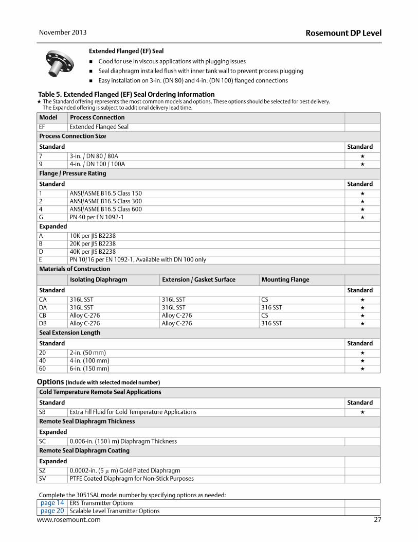
Extended Flanged (EF) Seal
Good for use in viscous applications with plugging issues
Seal diaphragm installed flush with inner tank wall to prevent process plugging
Easy installation on 3-in. (DN 80) and 4-in. (DN 100) flanged connections
Table 5. Extended Flanged (EF) Seal Ordering Information★ The Standard offering represents the most common models and options. These options should be selected for best delivery.__The Expanded offering is subject to additional delivery lead time.
Model Process Connection
EF Extended Flanged Seal
Process Connection Size
Standard Standard
7 3-in. / DN 80 / 80A ★
9 4-in. / DN 100 / 100A ★
Flange / Pressure Rating
Standard Standard
1 ANSI/ASME B16.5 Class 150 ★
2 ANSI/ASME B16.5 Class 300 ★
4 ANSI/ASME B16.5 Class 600 ★
G PN 40 per EN 1092-1 ★
Expanded
A 10K per JIS B2238B 20K per JIS B2238D 40K per JIS B2238E PN 10/16 per EN 1092-1, Available with DN 100 only
Materials of Construction
Isolating Diaphragm Extension / Gasket Surface Mounting Flange
Standard Standard
CA 316L SST 316L SST CS ★
DA 316L SST 316L SST 316 SST ★
CB Alloy C-276 Alloy C-276 CS ★
DB Alloy C-276 Alloy C-276 316 SST ★
Seal Extension Length
Standard Standard
20 2-in. (50 mm) ★
40 4-in. (100 mm) ★
60 6-in. (150 mm) ★
Options (Include with selected model number)
Cold Temperature Remote Seal Applications
Standard Standard
SB Extra Fill Fluid for Cold Temperature Applications ★
Remote Seal Diaphragm Thickness
Expanded
SC 0.006-in. (150 ì m) Diaphragm Thickness
Remote Seal Diaphragm Coating
Expanded
SZ 0.0002-in. (5 m) Gold Plated DiaphragmSV PTFE Coated Diaphragm for Non-Stick Purposes
Complete the 3051SAL model number by specifying options as needed:page 14 ERS Transmitter Optionspage 20 Scalable Level Transmitter Options

Rosemount DP Level November 2013
Remote Flanged (RF) Seal
Designed to improve performance on smaller process connections
Easy installation on flanged connections ranging from 1-in. to 1.5-in. (DN 50 – DN 40)
Lower housing / flushing ring required
Table 6. Remote Flanged (RF) Seal Ordering Information★ The Standard offering represents the most common models and options. These options should be selected for best delivery.__The Expanded offering is subject to additional delivery lead time.
Model Process Connection
RF Remote Flanged Seal
Process Connection Size
Standard Standard
2 1-in. / 25A ★
4 1.5-in. / 40A ★
D DN 25 ★
F DN 40 ★
Flange / Pressure Rating
Standard Standard
1 ANSI/ASME B16.5 Class 150 ★
2 ANSI/ASME B16.5 Class 300 ★
4 ANSI/ASME B16.5 Class 600 ★
G PN 40 per EN 1092-1 ★
Expanded
A 10K per JIS B2238B 20K per JIS B2238D 40K per JIS B2238
Materials of Construction
Isolating Diaphragm Upper Housing Flange
Standard Standard
CA 316L SST 316L SST CS ★
DA 316L SST 316L SST 316 SST ★
CB Alloy C-276 316L SST CS ★
DB Alloy C-276 316L SST 316 SST ★
CC Tantalum 316L SST CS ★
DC Tantalum 316L SST 316 SST ★
Flushing Connection Ring Material (Lower Housing)(1)
Standard Standard
A 316L SST ★
B Alloy C-276 ★
D Plated CS ★
Number of Flushing Connections
Standard Standard
1 One ¼-18 NPT Flushing Connection ★
3 Two ¼-18 NPT Flushing Connections ★
5 None ★
28 www.rosemount.com

Rosemount DP LevelNovember 2013
Options (Include with selected model number)
Remote Seal Diaphragm Thickness
Standard Standard
SB Extra Fill Fluid for Cold Temperature Applications ★
Remote Seal Diaphragm Thickness
Expanded
SC(2) 0.006-in. (150 ì m) Diaphragm Thickness
Remote Seal Flushing Connection Plug, Drain/Vent
Standard Standard
SD Alloy C-276 Plug(s) for Flushing Connection(s) ★
SG 316 SST Plug(s) for Flushing Connection(s) ★
SH 316 SST Drain / Vent(s) for Flushing Connection(s) ★
Remote Seal Gasket Material
Standard Standard
SJ PTFE Gasket (for use with Flushing Connection Ring) ★
Expanded
SK Barium Sulfate-Filled PTFE Gasket (for use with Flushing Connection Ring)SN Grafoil Gasket (for use with Flushing Connection Ring)
Remote Seal Diaphragm Coating
Expanded
SZ(2) 0.0002-in. (5 m) Gold Plated DiaphragmSV PTFE Coated Diaphragm for Non-Stick Purposes
Complete the 3051SAL model number by specifying options as needed:page 14 ERS Transmitter Optionspage 20 Scalable Level Transmitter Options
(1) Supplied with C4401 Aramid fiber gasket.
(2) Not available with Tantalum diaphragms (Material of Construction codes CC and DC).
Table 6. Remote Flanged (RF) Seal Ordering Information★ The Standard offering represents the most common models and options. These options should be selected for best delivery.__The Expanded offering is subject to additional delivery lead time.
29www.rosemount.com

Rosemount DP Level November 2013
Remote Threaded (RT) Seal
For use with threaded process connections (1/4-18 to 1-11.5 NPT)
Rated for use in high-pressure applications (up to 2500 PSI)
Optional flushing connections available
Table 7. RT Threaded Seal Ordering Information★ The Standard offering represents the most common models and options. These options should be selected for best delivery.
__The Expanded offering is subject to additional delivery lead time.
Process Connection Style
Standard Standard
RT Remote Threaded Seal ★
Process Connection Size
Standard Standard
3 1/2-14 NPT ★
4 3/4-14 NPT ★
5 1-11.5 NPT ★
Expanded
1 1/4-18 NPT
Pressure Rating
Standard Standard
0 2500 psi ★
Isolating Diaphragm Material Upper Housing Material Flange
Standard Standard
CA 316L SST 316L SST CS ★
DA 316L SST 316L SST 316 SST ★
CB Alloy C-276 316L SST CS ★
DB Alloy C-276 316L SST 316 SST ★
CC Tantalum 316L SST CS ★
DC Tantalum 316L SST 316 SST ★
Flushing Connection Ring Material (Lower Housing)(1) (2)
Standard Standard
A 316L SST ★
B Alloy C-276 ★
Expanded
D Plated CS
Number of Flushing Connections
Standard Standard
1 One 1/4-in. Flushing Connection ★
3 Two 1/4-in. Flushing Connections ★
5 No Flushing Connection ★
30 www.rosemount.com

Rosemount DP LevelNovember 2013
Options (Include with selected model number)
Remote Seal Diaphragm Thickness
Standard Standard
SB Extra Fill Fluid for Cold Temperature Applications ★
Remote Seal Diaphragm Thickness
Expanded
SC(3) 0.006-in. (150 ì m) Diaphragm Thickness
Remote Seal Flushing Plug, Drain/Vent
Standard Standard
SD Alloy C-276 Plug(s) for Flushing Connection(s) ★
SG 316 SST Plug(s) for Flushing Connection(s) ★
SH 316 SST Drain / Vent(s) for Flushing Connection(s) ★
Remote Seal Gasket Material
Standard Standard
SJ PTFE Gasket (for use with Flushing Connection Ring) ★
SN Grafoil Gasket (for use with Flushing Connection Ring) ★
SR Ethylene Propylene Gasket (for use with Flushing Connection Ring) ★
Expanded
SK Barium Sulfate-Filled PTFE Gasket (for use with Flushing Connection Ring)
Remote Seal Bolt
Standard Standard
S3 304 SST Bolts ★
Expanded
S4 316 SST Bolts
Remote Seal Diaphragm Coating
Expanded
SZ(3) 0.0002-in. (5 m) Gold Plated DiaphragmSV PTFE Coated Diaphragm for Non-Stick Purposes
Complete the 3051SAL model number by specifying options as needed:page 14 ERS Transmitter Optionspage 20 Scalable Level Transmitter Options
(1) Supplied with C4401 aramid fiber gasket.
(2) Flushing Connection Ring/ Lower Housing assembly bolts provided as standard are carbon steel.
(3) Not available with Tantalum diaphragms (Material of Construction codes CC and DC).
Table 7. RT Threaded Seal Ordering Information★ The Standard offering represents the most common models and options. These options should be selected for best delivery.
__The Expanded offering is subject to additional delivery lead time.
31www.rosemount.com

Rosemount DP Level November 2013
32 www.rosemount.com
Hygienic Tri-Clamp (SC) Seal Good for use in hygienic applications Easy installation on Tri-Clover style Tri-Clamp® connections (1.5-in. to 3-in.) Conforms to 3-A standard 74-03
Table 8. SC Hygienic Tri-Clover Style Tri-Clamp Seal Ordering Information★ The Standard offering represents the most common models and options. These options should be selected for best delivery.
__The Expanded offering is subject to additional delivery lead time.
Process Connection
Standard Standard
SC(1)
(1) Clamp and gasket furnished by user. The maximum working pressure is dependent upon the clamp pressure rating.
Tri-Clover Style Tri-Clamp Seal ★
Process Connection Size
Standard Standard
3(2)
(2) Rosemount 1199 Remote Seal Minimum Span Summary calls out a minimum span of 500 inH2O or 2490 mbar for 1-1/2” SSCW
1½ in. ★
5(3)
(3) Rosemount 1199 Remote Seal Minimum Span Summary calls out a minimum span of 50 inH2O or 373 mbar for 2” SSCW
2 in. ★
7 3 in. ★
Maximum Working Pressure
Standard Standard
0 1000 PSI ★
Isolating Diaphragm Material Upper Housing Material
Standard Standard
LA00 316L SST 316L SST ★
Expanded
LB00 Alloy C-276 316L SST
Options (Include with selected model number)
Remote Seal Diaphragm Polishing
Expanded
R6 Electropolishing
Remote Seal Diaphragm Surface Finish
Expanded
RD 10 in. (0.25 m) Ra Diaphragm Surface FinishRG 15 in. (0.375 m) Ra Diaphragm Surface FinishRH 20 in. (0.5 m) Ra Diaphragm Surface Finish
Surface Finish Certification
Standard Standard
Q16(4)
(4) Q16 is only available when the diaphragm seal has surface finish options (RD, RG, and RH)
Surface Finish Certification for Hygienic Remote Seals ★
Complete the 3051SAL model number by specifying options as needed:page 14 ERS Transmitter Optionspage 20 Scalable Level Transmitter Options

Rosemount DP LevelNovember 2013
33www.rosemount.com
Hygienic Tank Spud (SS) Seal
Commonly used in hygienic level applications
Seal diaphragm installed flush with inner tank wall
Conforms to 3-A standard 74-03
Table 9. SS Hygienic Tank Spud Seal Ordering Information★ The Standard offering represents the most common models and options. These options should be selected for best delivery.
__The Expanded offering is subject to additional delivery lead time.
Process Connection
Standard Standard
SS(1) Hygienic Tank Spud Seal ★
Process Connection Size
Standard Standard
A 4-in. Sch. 5 Tri-Clamp ★
Maximum Working Pressure (Clamp Rating)
Standard Standard
0 600 PSI (41 bar) ★
Upper Housing
Standard Standard
A 316L SST ★
Diaphragm and Wetted, Extension Material
Diaphragm and Wetted Extension
Standard Standard
AL 316L SST(2) 316L SST(2) ★
Expanded
BB Alloy C-276 316L SST
Extension Length
Standard Standard
2 2-in. (50 mm) Extension ★
6 6-in. (150 mm) Extension ★
Options (Include with selected model number)
Remote Seal Diaphragm Thickness
Expanded
SC 0.006-in. (150 m) Diaphragm Thickness
Tank Spud Included with Shipment
Standard Standard
S1 Tank Spud Included with Shipment ★
Remote Seal Diaphragm Polishing
Expanded
R6 Electropolishing
Remote Seal Diaphragm Surface Finish
Expanded
RH 20 in. (0.5 m) Ra Diaphragm Surface FinishRG(3) 15 in. (0.375 m) Ra Diaphragm Surface Finish

Rosemount DP Level November 2013
Additional OptionsSurface Finish Certification
Standard Standard
Q16(4) Surface Finishing Certification for Hygienic Remote Seals ★
Complete the 3051SAL model number by specifying options as needed:page 14 ERS Transmitter Optionspage 20 Scalable Level Transmitter Options
(1) Clamp and Ethylene Propylene o-ring (conforms to 3-A standard 74 and USP class VI) supplied.
(2) Diaphragm brazed and TIG-welded to extension.
(3) Require Option code R6 (Electropolishing).
(4) Q16 is only available when the diaphragm seal has surface finish options (RG and RH).
Table 9. SS Hygienic Tank Spud Seal Ordering Information★ The Standard offering represents the most common models and options. These options should be selected for best delivery.
__The Expanded offering is subject to additional delivery lead time.
34 www.rosemount.com

Rosemount DP LevelNovember 2013
Rosemount 3051L Level Transmitter
Rosemount 3051L level transmitters combine the features and benefits of a 3051 pressure transmitter with the durability and reliability of a direct mount seal all in a single model number.
Level transmitters can also be ordered with an additional 1199 remote seal to form a Tuned-System Assembly that offers improved performance and reduced costs compared to traditional symmetrical (balanced) assemblies.
Product features and capabilities include:
Variety of process connections
Quantified performance for the entire transmitter / seal assembly (QZ option)
4-20 mA HART, FOUNDATION fieldbus, Profibus-PA, and 1-5 Vdc HART low power protocols
Additional InformationSpecifications: page 101Certifications: page 122Dimensional Drawings: page 130
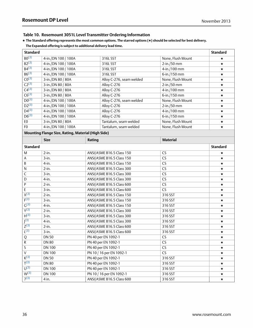
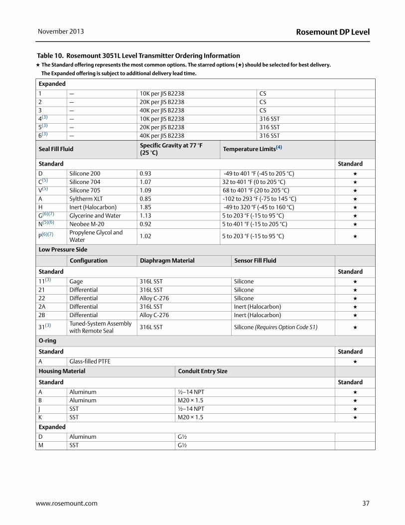
Table 10. Rosemount 3051L Level Transmitter Ordering Information★ The Standard offering represents the most common options. The starred options (★) should be selected for best delivery.
__The Expanded offering is subject to additional delivery lead time.
Model Transmitter Type
3051L Level Transmitter
Pressure Range
Standard Standard
2 –250 to 250 inH2O (–0,6 to 0,6 bar) ★
3 –1000 to 1000 inH2O (–2,5 to 2,5 bar) ★
4 –300 to 300 psi (–20,7 to 20,7 bar) ★
Transmitter Output
Standard Standard
A 4–20 mA with Digital Signal Based on HART Protocol ★
F FOUNDATION fieldbus Protocol ★
W(1) Profibus – PA Protocol ★
Expanded
M(2) Low-Power 1–5 Vdc with Digital Signal Based on HART Protocol (See Option Code C2 for 0.8–3.2 Vdc Output)
Process Connection Size, Material, Extension Length (High Side)
Standard Standard
Code Process Connection Size Material Extension Length ★
G0(3) 2-in./DN 50 / 50A 316L SST None, Flush Mount ★
H0(3) 2-in./DN 50 / 50A Alloy C-276, seam welded None, Flush Mount ★
J0 2-in./DN 50 / 50A Tantalum, seam welded None, Flush Mount ★
A0(3) 3-in./DN 80 / 80A 316L SST None, Flush Mount ★
A2(3) 3-in./DN 80 / 80A 316L SST 2-in./50 mm ★
A4(3) 3-in./DN 80 / 80A 316L SST 4-in./100 mm ★
A6(3) 3-in./DN 80 / 80A 316L SST 6-in./150 mm ★
35www.rosemount.com
Rosemount DP Level November 2013
Standard Standard
B0(3) 4-in./DN 100 / 100A 316L SST None, Flush Mount ★
B2(3) 4-in./DN 100 / 100A 316L SST 2-in./50 mm ★
B4(3) 4-in./DN 100 / 100A 316L SST 4-in./100 mm ★
B6(3) 4-in./DN 100 / 100A 316L SST 6-in./150 mm ★
C0(3) 3-in./DN 80 / 80A Alloy C-276, seam welded None, Flush Mount ★
C2(3) 3-in./DN 80 / 80A Alloy C-276 2-in./50 mm ★
C4(3) 3-in./DN 80 / 80A Alloy C-276 4-in./100 mm ★
C6(3) 3-in./DN 80 / 80A Alloy C-276 6-in./150 mm ★
D0(3) 4-in./DN 100 / 100A Alloy C-276, seam welded None, Flush Mount ★
D2(3) 4-in./DN 100 / 100A Alloy C-276 2-in./50 mm ★
D4(3) 4-in./DN 100 / 100A Alloy C-276 4-in./100 mm ★
D6(3) 4-in./DN 100 / 100A Alloy C-276 6-in./150 mm ★
E0 3-in./DN 80 / 80A Tantalum, seam welded None, Flush Mount ★
F0 4-in./DN 100 / 100A Tantalum, seam welded None, Flush Mount ★
Mounting Flange Size, Rating, Material (High Side)
Size Rating Material
Standard Standard
M 2-in. ANSI/ASME B16.5 Class 150 CS ★
A 3-in. ANSI/ASME B16.5 Class 150 CS ★
B 4-in. ANSI/ASME B16.5 Class 150 CS ★
N 2-in. ANSI/ASME B16.5 Class 300 CS ★
C 3-in. ANSI/ASME B16.5 Class 300 CS ★
D 4-in. ANSI/ASME B16.5 Class 300 CS ★
P 2-in. ANSI/ASME B16.5 Class 600 CS ★
E 3-in. ANSI/ASME B16.5 Class 600 CS ★
X(3) 2-in. ANSI/ASME B16.5 Class 150 316 SST ★
F(3) 3-in. ANSI/ASME B16.5 Class 150 316 SST ★
G(3) 4-in. ANSI/ASME B16.5 Class 150 316 SST ★
Y(3) 2-in. ANSI/ASME B16.5 Class 300 316 SST ★
H(3) 3-in. ANSI/ASME B16.5 Class 300 316 SST ★
J(3) 4-in. ANSI/ASME B16.5 Class 300 316 SST ★
Z(3) 2-in. ANSI/ASME B16.5 Class 600 316 SST ★
L(3) 3-in. ANSI/ASME B16.5 Class 600 316 SST ★
Q DN 50 PN 40 per EN 1092-1 CS ★
R DN 80 PN 40 per EN 1092-1 CS ★
S DN 100 PN 40 per EN 1092-1 CS ★
V DN 100 PN 10 / 16 per EN 1092-1 CS ★
K(3) DN 50 PN 40 per EN 1092-1 316 SST ★
T(3) DN 80 PN 40 per EN 1092-1 316 SST ★
U(3) DN 100 PN 40 per EN 1092-1 316 SST ★
W(3) DN 100 PN 10 / 16 per EN 1092-1 316 SST ★
7(3) 4 in. ANSI/ASME B16.5 Class 600 316 SST ★
Table 10. Rosemount 3051L Level Transmitter Ordering Information★ The Standard offering represents the most common options. The starred options (★) should be selected for best delivery.
__The Expanded offering is subject to additional delivery lead time.
36 www.rosemount.com
Rosemount DP LevelNovember 2013
Expanded
1 — 10K per JIS B2238 CS2 — 20K per JIS B2238 CS3 — 40K per JIS B2238 CS4(3) — 10K per JIS B2238 316 SST5(3) — 20K per JIS B2238 316 SST6(3) — 40K per JIS B2238 316 SST
Seal Fill FluidSpecific Gravity at 77 °F (25 °C)
Temperature Limits(4)
Standard Standard
D Silicone 200 0.93 -49 to 401 °F (-45 to 205 °C) ★
C(5) Silicone 704 1.07 32 to 401 °F (0 to 205 °C) ★
V(5) Silicone 705 1.09 68 to 401 °F (20 to 205 °C) ★
A Syltherm XLT 0.85 -102 to 293 °F (-75 to 145 °C) ★
H Inert (Halocarbon) 1.85 -49 to 320 °F (-45 to 160 °C) ★
G(6)(7) Glycerine and Water 1.13 5 to 203 °F (-15 to 95 °C) ★
N(5)(6) Neobee M-20 0.92 5 to 401 °F (-15 to 205 °C) ★
P(6)(7) Propylene Glycol and Water
1.02 5 to 203 °F (-15 to 95 °C) ★
Low Pressure Side
Configuration Diaphragm Material Sensor Fill Fluid
Standard Standard
11(3) Gage 316L SST Silicone ★
21 Differential 316L SST Silicone ★
22 Differential Alloy C-276 Silicone ★
2A Differential 316L SST Inert (Halocarbon) ★
2B Differential Alloy C-276 Inert (Halocarbon) ★
31(3) Tuned-System Assembly with Remote Seal
316L SST Silicone (Requires Option Code S1) ★
O-ring
Standard Standard
A Glass-filled PTFE ★
Housing Material Conduit Entry Size
Standard Standard
A Aluminum ½–14 NPT ★
B Aluminum M20 × 1.5 ★
J SST ½–14 NPT ★
K SST M20 × 1.5 ★
Expanded
D Aluminum G½M SST G½
Table 10. Rosemount 3051L Level Transmitter Ordering Information★ The Standard offering represents the most common options. The starred options (★) should be selected for best delivery.
__The Expanded offering is subject to additional delivery lead time.
37www.rosemount.com

Rosemount DP Level November 2013
Options (Include with selected model number)
PlantWeb Control Functionality
Standard Standard
A01 FOUNDATION fieldbus Advanced Control Function Block Suite ★
PlantWeb Diagnostic Functionality
Standard Standard
D01 FOUNDATION fieldbus Diagnostics Suite ★
Seal Assemblies
Standard Standard
S1(8) Assembled to One Rosemount 1199 Seal (Requires 1199M) ★
Product Certifications
Standard Standard
E5 FM Explosion-proof, Dust Ignition-proof ★
I5 FM Intrinsically Safe, Division 2 ★
K5 FM Explosion-proof, Dust Ignition-proof, Intrinsically Safe, and Division 2 ★
I1(9) ATEX Intrinsic Safety and Dust ★
N1(9) ATEX Type n Certification and Dust ★
E8 ATEX Flameproof and Dust Certification ★
E4(9) TIIS Flameproof ★
E3 China Flameproof ★
I3 China Intrinsic Safety, Dust Ignition-proof ★
C6 CSA Explosion-proof, Dust Ignition-proof, Intrinsically Safe, and Division 2 ★
K6(9) CSA and ATEX Explosion-proof, Intrinsically Safe, and Division 2 (combination of C6 and K8) ★
KBFM and CSA Explosion-proof, Dust Ignition-proof, Intrinsically Safe, and Division 2 (combination of K5 and C6)
★
K7 IECEx Flameproof, Dust Ignition-proof, Intrinsic Safety, and Type n (combination of I7, N7, and E7) ★
K8(9) ATEX Flame-proof and Intrinsic Safety Approvals (combination of I1 and E8) ★
KD(9) FM, CSA, and ATEX Explosion-proof, Intrinsically Safe (combination of K5, C6, I1, and E8) ★
I7 IECEx Intrinsic Safety ★
E7 IECEx Flameproof, Dust Ignition-proof ★
N7 IECEx Type n Certification ★
IA ATEX FISCO Intrinsic Safety ★
IE FM FISCO Intrinsically Safe ★
E2 INMETRO Flameproof ★
I2 INMETRO Intrinsic Safety ★
K2 INMETRO Flameproof, Intrinsic Safety ★
Shipboard Approvals
Standard Standard
SBS American Bureau of Shipping (ABS) Type Approval ★
SBV Bureau Veritas (BV) Type Approval ★
SDN Det Norske Veritas (DNV) Type Approval ★
SLL Lloyds Register (LR) Type Approval ★
Table 10. Rosemount 3051L Level Transmitter Ordering Information★ The Standard offering represents the most common options. The starred options (★) should be selected for best delivery.
__The Expanded offering is subject to additional delivery lead time.
38 www.rosemount.com

Rosemount DP LevelNovember 2013
Bolting Material
Standard Standard
L4 Austenitic 316 SST Bolts ★
L5 ASTM A 193, Grade B7M bolts ★
L6 Alloy K-500 Bolts ★
L8 ASTM A 193 Class 2, Grade B8M Bolts ★
Display Type
Standard Standard
M4(10) LCD Display with Local Operator Interface ★
M5 LCD Display for Aluminum Housing (Housing Codes A, B, C, and D only) ★
M6 LCD Display for SST Housing (Housing Codes J, K, L, and M only) ★
Calibration Certification
Standard Standard
Q4 Calibration Certificate ★
QP Calibration Certificate and tamper evident seal ★
QG Calibration Certificate and GOST Verification Certificate ★
Material Traceability Certification
Standard Standard
Q8 Material Traceability Certification per EN 10204 3.1 ★
Quality Certification for Safety
Standard Standard
QS(11) Prior-use certificate of FMEDA data ★
Conduit Electrical Connector
Standard Standard
GE M12, 4-pin, Male Connector (eurofast®) ★
GM A size Mini, 4-pin, Male Connector (minifast®) ★
Configuration Buttons
Standard Standard
J1(12)(13) Local Zero Adjustment Only ★
J3(12)(13) No Local Zero or Span Adjustment ★
Transient Protection
Standard Standard
T1(14) Transient Protection Terminal Block ★
Software Configuration
Standard Standard
C1(12) Custom Software Configuration (Completed CDS 00806-0100-4001 required with order) ★
Low Power Output
Standard Standard
C2(12) 0.8–3.2 Vdc Output with Digital Signal Based on HART Protocol (Available with Output code M only) ★
Table 10. Rosemount 3051L Level Transmitter Ordering Information★ The Standard offering represents the most common options. The starred options (★) should be selected for best delivery.
__The Expanded offering is subject to additional delivery lead time.
39www.rosemount.com

Rosemount DP Level November 2013
Alarm Limit
Standard Standard
C4(12)(15) NAMUR alarm and saturation levels, high alarm ★
CN(12)(15) NAMUR alarm and saturation levels, low alarm ★
CR Custom alarm and saturation signal levels, high alarm ★
CS Custom alarm and saturation signal levels, low alarm ★
CT Low alarm (standard Rosemount alarm and saturation levels) ★
Conduit Plug
Standard Standard
D0 316 SST Conduit Plug ★
Ground Screw
Standard Standard
V5(16) External Ground Screw Assembly ★
Lower Housing Flushing Connection Options
Ring Material Number Size (NPT)
Standard Standard
F1 316 SST 1 1/4-18 NPT ★
F2 316 SST 2 1/4-18 NPT ★
F3 Alloy C-276 1 1/4-18 NPT ★
F4 Alloy C-276 2 1/4-18 NPT ★
F7 316 SST 1 1/2-14 NPT ★
F8 316 SST 2 1/2-14 NPT ★
F9 Alloy C-276 1 1/2-14 NPT ★
F0 Alloy C-276 2 1/2-14 NPT ★
Flange Adapters
Standard Standard
DF(17) 1/2-14 NPT flange adapter ★
RC1/4 RC1/2 Process Connection
Expanded
D9(17) JIS Process Connection - RC 1/2 Flange Adapter
Toolkit Total System Performance Reports
Standard Standard
QZ Remote Seal System Performance Calculation Report ★
Typical Model Number: 3051L 2 A A0 A D 21 A A F1
(1) Option Code M4 - LCD Display with Local Operator Interface required for local addressing and configuration.
(2) Not available with hazardous certification Option Codes I1, N1, E4, K6, and K8.
(3) Materials of Construction comply with metallurgical requirements highlighted within NACE MR 0175 / ISO 15156 for sour oil field production environments. Environmental limits apply to certain materials. Consult latest standard for details. Selected materials also conform to NACE MR 0103 for sour refining environments.
(4) At ambient pressure of 14.7 psia (1 bar-a) and ambient temperature of 70°F (21°C). Temperature limits are reduced in vacuum service and may be limited by seal selection.
(5) Maximum process temperature is limited by heat transfer to the transmitter and must be further derated if ambient, temperature exceeds 70 °F (21 °C).
(6) This is a food grade fill fluid.
Table 10. Rosemount 3051L Level Transmitter Ordering Information★ The Standard offering represents the most common options. The starred options (★) should be selected for best delivery.
__The Expanded offering is subject to additional delivery lead time.
40 www.rosemount.com

Rosemount DP LevelNovember 2013
(7) Not suitable for vacuum applications.
(8) “Assemble-to” items are specified separately and require a completed model number.
(9) Not available with low-power Option Code M
(10) Available only with output code W - Profibus PA
(11) Only available with HART 4-20 mA output (output code A).
(12) Not available with fieldbus (output code F) or profibus protocols (output code W).
(13) Local zero and span adjustments are standard unless Option Code J1 or J3 is specified.
(14) The T1 option is not needed with FISCO Product Certifications; transient protection is included in the FISCO product certification codes IA, IE, IF, and IG.
(15) NAMUR-Compliant operation is pre-set at the factory and cannot be changed to standard operation in the field.
(16) The V5 option is not needed with the T1 option; external ground screw assembly is included with the T1 option.
(17) Not available with Remote Mount Seal Assembly option S1.
41www.rosemount.com

Rosemount DP Level November 2013
dard
★
★
★
dard
★
★
★
dard
★
★
★
★
★
★
★
★
★
Rosemount 2051L Level TransmitterRosemount 2051L level transmitters combine the features and benefits of a 2051 pressure transmitter with the durability and reliability of a direct mount seal all in a single model number.
Level transmitters can also be ordered with an additional 1199 remote seal to form a Tuned-System Assembly that offers improved performance and reduced costs compared to traditional symmetrical (balanced) assemblies.
Product features and capabilities include:
Variety of process connections
Quantified performance for the entire transmitter / seal assembly (QZ option)
4-20 mA HART, FOUNDATION fieldbus, and 1-5 Vdc HART Low-Power outputs
Additional InformationSpecifications: page 101Certifications: page 127Dimensional Drawings: page 130
Table 11. Rosemount 2051L Level Transmitter Ordering Information★ The Standard offering represents the most common options. The starred options (★) should be selected for best delivery.
__The Expanded offering is subject to additional delivery lead time.
Model Transmitter Type
2051L Level Transmitter
Pressure Range
Standard Stan
2 –250 to 250 inH2O (–0,6 to 0,6 bar)3 –1000 to 1000 inH2O (–2,5 to 2,5 bar)4 –300 to 300 psi (–20,7 to 20,7 bar)
Transmitter Output
Standard Stan
A 4–20 mA with Digital Signal Based on HART ProtocolF FOUNDATION fieldbus ProtocolW(1) Profibus - PA Protocol
Expanded
M Low-Power, 1–5 Vdc with Digital Signal Based on HART Protocol
Process Connection Size, Diaphragm Material (High Side)
Process Connection Size Diaphragm
Standard Stan
G(2) 2 in./DN 50 316L SST, seam weldedH(2) 2 in./DN 50 Alloy C-276, seam weldedJ 2 in./DN 50 TantalumA(2) 3 in./DN 80 316L SSTB(2) 4 in./DN 100 316L SSTC(2) 3 in./DN 80 Alloy C-276, seam weldedD(2) 4 in./DN 100 Alloy C-276, seam weldedE 3 in./DN 80 Tantalum, seam weldedF 4 in./DN 100 Tantalum, seam welded
Tuned-System Assembly Comprised of 2051L with 1199 Remote Mount Seal
42 www.rosemount.com

Rosemount DP LevelNovember 2013
dard
★
★
★
★
dard
★
★
★
★
★
★
★
★
★
★
★
★
★
★
★
★
dard
★
★
★
★
★
★
★
★
dard
★
★
★
Transmitter Extension Length (High Side)
Standard Stan
0 None, Flush Mount2 2 in./50 mm4 4 in./100 mm6 6 in./150 mm
Mounting Flange Size, Rating, Material (High Side)
Size Rating Material
Standard Stan
M 2-in. ANSI/ASME B16.5 Class 150 CSA 3-in. ANSI/ASME B16.5 Class 150 CSB 4-in. ANSI/ASME B16.5 Class 150 CSN 2-in. ANSI/ASME B16.5 Class 300 CSC 3-in. ANSI/ASME B16.5 Class 300 CSD 4-in. ANSI/ASME B16.5 Class 300 CSX(2) 2-in. ANSI/ASME B16.5 Class 150 316 SSTF(2) 3-in. ANSI/ASME B16.5 Class 150 316 SSTG(2) 4-in. ANSI/ASME B16.5 Class 150 316 SSTY(2) 2-in. ANSI/ASME B16.5 Class 300 316 SSTH(2) 3-in. ANSI/ASME B16.5 Class 300 316 SSTJ(2) 4-in. ANSI/ASME B16.5 Class 300 316 SSTQ DN50 PN 40 per EN 1092-1 CSR DN80 PN 40 per EN 1092-1 CSK(2) DN50 PN 40 per EN 1092-1 316 SSTT(2) DN80 PN 40 per EN 1092-1 316 SST
Seal Fill FluidSpecific Gravity at 77 °F (25 °C) Temperature Limits(3)
Standard Stan
D Silicone 200 0.93 -49 to 401 °F (-45 to 205 °C)C(4) Silicone 704 1.07 32 to 401 °F (0 to 205 °C)V(4) Silicone 705 1.09 68 to 401 °F (20 to 205 °C)A Syltherm XLT 0.85 -102 to 293 °F (-75 to 145 °C)H Inert (Halocarbon) 1.85 -49 to 320 °F (-45 to 160 °C)G(5)(6) Glycerin and Water 1.13 5 to 203 °F (-15 to 95 °C)N(4) Neobee M-20 0.92 5 to 401 °F (-15 to 205 °C)P(5)(6) Propylene Glycol and Water 1.02 5 to 203 °F (-15 to 95 °C)
Sensor Module Configuration, Flange Adapter (Low Side)
Configuration
Standard Stan
1(2) Gage2 Differential3(2) Tuned-System Assembly with Remote Seal
Sensor Module Diaphragm Material, Sensor Fill Fluid (Low Side)
Table 11. Rosemount 2051L Level Transmitter Ordering Information★ The Standard offering represents the most common options. The starred options (★) should be selected for best delivery.
__The Expanded offering is subject to additional delivery lead time.
43www.rosemount.com

Rosemount DP Level November 2013
dard
★
★
★
★
★
★
dard
★
dard
★
★
★
★
dard
★
dard
★
dard
★
★
★
★
★
★
★
★
★
★
★
★
★
★
★
★
Diaphragm Material Sensor Fill Fluid
Standard Stan
1(2) 316L SST Silicone2(2) Alloy C-276 (SST Valve Seat) Silicone7(2) Alloy C-276 (SST Valve Seat) SiliconeA(2) 316L SST Inert (Halocarbon)B(2) Alloy C-276 (SST Valve Seat) Inert (Halocarbon)G(2) Alloy C-276 (SST Valve Seat) Inert (Halocarbon)
O-ring
Standard Stan
A Glass-filled PTFE
Housing Material, Conduit Entry Size
Housing Material Conduit Entry Size
Standard Stan
A Aluminum ½–14 NPTB Aluminum M20 × 1.5J SST ½–14 NPTK SST M20 × 1.5
Expanded
D Aluminum G½M SST G½
Options (Include with selected model number)
PlantWeb Control Functionality
Standard Stan
A01 FOUNDATION fieldbus Advanced Control Function Block Suite
Seal Assemblies
Standard Stan
S1(7) Assemble to One Rosemount 1199 Seal (Requires 1199M)
Product Certifications
Standard Stan
E1(8) ATEX FlameproofE2(8) INMETRO FlameproofE3(8) China FlameproofE4 TIIS FlameproofE5 FM Explosion-proof, Dust Ignition-proofE6 CSA Explosion-proof, Dust Ignition-proof, Division 2E7(8) IECEx FlameproofEW India (CCOE) Flameproof ApprovalI1(8) ATEX Intrinsic SafetyI2(8) INMETRO Intrinsically SafeI3(8) China Intrinsic SafetyI5 FM Intrinsically Safe, Division 2I6 CSA Intrinsically SafeI7(8) IECEx Intrinsic SafetyIA(9) ATEX FISCO Intrinsic SafetyIE(9) FM FISCO Intrinsically Safe
Table 11. Rosemount 2051L Level Transmitter Ordering Information★ The Standard offering represents the most common options. The starred options (★) should be selected for best delivery.
__The Expanded offering is subject to additional delivery lead time.
44 www.rosemount.com

Rosemount DP LevelNovember 2013
dard
★
★
★
★
★
★
★
★
★
★
★
★
★
★
★
dard
★
★
★
★
dard
★
★
dard
★
dard
★
dard
★
dard
★
dard
★
Standard Stan
IF(9) CSA FISCO Intrinsically Safe
IG(9) IECEx FISCO Intrinsically Safe
IW India (CCOE) Intrinsic Safety ApprovalK1(8) ATEX Flameproof, Intrinsic Safety, Type n, DustK2 INMETRO Flameproof, Intrinsic Safety, Type nK5 FM Explosion-proof, Dust Ignition-proof, Intrinsically Safe, Division 2K6 CSA Explosion-proof, Dust Ignition-proof, Intrinsically Safe, Division 2K7(8) IECEx Flameproof, Intrinsic Safety, Type nKA(8) ATEX and CSA Flameproof, Intrinsically Safe, Division 2KB FM and CSA Explosion-proof, Dust Ignition-proof, Intrinsically Safe, Division 2KC(8) FM and ATEX Explosion-proof, Intrinsically Safe, Division 2KD(8) FM, CSA, and ATEX Explosion-proof, Intrinsically SafeN1(8) ATEX Type nN7(8) IECEx Type nND(8) ATEX Dust
Shipboard Approvals
Standard Stan
SBS American Bureau of Shipping (ABS) Type ApprovalSBV Bureau Veritas (BV) Type ApprovalSDN Det Norske Veritas (DNV) Type ApprovalSLL Lloyds Register (LR) Type Approval
Digital Display
Standard Stan
M4(10) LCD Display With Local Operator InterfaceM5 LCD display
Hardware Adjustments
Standard Stan
D4(11) Zero and Span Hardware Adjustments
Flange Adapters
Standard Stan
DF(12) 1/2-14 NPT Flange Adapters
Conduit Plug
Standard Stan
DO(13) 316 SST Conduit Plug
RC1/4 RC1/2 Process Connection
Expanded
D9(11) JIS Process Connection - RC 1/2 Flange Adapter
Ground Screw
Standard Stan
V5(14) External Ground Screw Assembly
Transient Protection
Standard Stan
T1(15) Transient Terminal Block
Table 11. Rosemount 2051L Level Transmitter Ordering Information★ The Standard offering represents the most common options. The starred options (★) should be selected for best delivery.
__The Expanded offering is subject to additional delivery lead time.
45www.rosemount.com

Rosemount DP Level November 2013
dard
★
dard
★
★
dard
★
dard
★
dard
★
dard
★
dard
★
★
★
★
★
★
★
★
ental
tion.
Software Configuration
Standard Stan
C1(16) Custom Software Configuration (Requires completed Configuration Data Sheet)
Alarm Limit
Standard Stan
C4(16)(17) NAMUR alarm and saturation levels, high alarmCN(16)(18) NAMUR alarm and saturation levels, low alarm
Calibration Certification
Standard Stan
Q4 Calibration Certificate1
Alarm Limit
Standard Stan
Q8 Material Traceability Certification per EN 10204 3.1
Quality Certification for Safety
Standard Stan
QS(16) Prior-use certificate of FMEDA data
Toolkit Total System Performance Reports
Standard Stan
QZ Remote Seal System Performance Calculation Report
Lower Housing Flushing Connection Ring Material Number Size (NPT)
Standard Stan
F1 316 SST 1 1/4-18 NPTF2 316 SST 2 1/4-18 NPTF3(18) Alloy C-276 1 1/4-18 NPTF4(18) Alloy C-276 2 1/4-18 NPTF7 316 SST 1 1/2-14 NPTF8 316 SST 2 1/2-14 NPTF9 Alloy C-276 1 1/2-14 NPTF0 Alloy C-276 2 1/2-14 NPT
Typical Model Number: 2051L 2 A A0 X D 21 A A B4 M5 F1
(1) Option Code M4 - LCD Display with Local Operator Interface required for local addressing and configuration.
(2) Materials of Construction comply with metallurgical requirements highlighted within NACE MR 0175 / ISO 15156 for sour oil field production environments. Environmlimits apply to certain materials. Consult latest standard for details. Selected materials also conform to NACE MR 0103 for sour refining environments.
(3) At ambient pressure of 14.7 psia (1 bar-a) and ambient temperature of 70 °F (21 °C). Temperature limits are reduced in vacuum service and may be limited by seal selec
(4) Maximum process temperature is limited by heat transfer to the transmitter electronics and must be further derated if ambient temperatures exceed 70 °F (21 °C).
(5) This is a food grade fill fluid.
(6) Not suitable for vacuum applications.
(7) “Assemble-to” items are specified separately and require a completed model number.
(8) Not available with Low Power output code M.
Table 11. Rosemount 2051L Level Transmitter Ordering Information★ The Standard offering represents the most common options. The starred options (★) should be selected for best delivery.
__The Expanded offering is subject to additional delivery lead time.
46 www.rosemount.com

Rosemount DP LevelNovember 2013
(9) Only valid with FOUNDATION fieldbus output code F.
(10) Available only with output code W-PROFIBUS PA.
(11) Not valid with FOUNDATION fieldbus output code F.
(12) Not available with Remote Mount Seal Assembly option S1.
(13) Transmitter is shipped with 316 SST conduit plug (uninstalled) in place of standard carbon steel conduit plug,
(14) The V5 option is not needed with the T1 option; external ground screw assembly is included with the T1 option.
(15) The T1 option is not needed with FISCO Product Certifications; transient protection is included in the FISCO product certification codes IA, IE, IF, and IG.
(16) Only available with HART 4-20 mA output (output code A).
(17) NAMUR-Compliant operation is pre-set at the factory and cannot be changed to standard operation in the field.
(18) Not available with Option Codes A0, B0, and G0.
47www.rosemount.com

Rosemount DP Level November 2013
Rosemount 1199 Direct Mount Seal Systems
Rosemount 1199 Direct Mount Seals reduce installation costs by eliminating mounting hardware. Their advanced design also minimizes oil volume improving performance.
Product features and capabilities include:
Direct Mount gage or absolute seal system can be used for open or vented to atmosphere tank applications
Tuned-System Assembly order codes can be used to improve performance for DP measurements in closed or pressurized tank applications
Variety of process connections
Quantified performance for the entire transmitter / seal assembly (QZ option)
Additional InformationSpecifications: page 113Dimensional Drawings: page 130
Rosemount 1199 Direct Mount Seal
The 1199 Direct Mount Seal also requires specification of a Rosemount pressure transmitter. See the appropriate Product Data Sheet for the desired transmitter and include the option indicated in the table below for the configuration desired.
Table 12. When ordering Rosemount 1199 Direct and Remote Mount Seals, please make sure to add the correct seal system ordering code to the transmitter model
Transmitter Model 2 Seals 1 Seal
3051S_C B12 B113051C - Welded-Repairable S2 S13051C - All Welded(1)
(1) All welded system connection types require either a 316L SST or Alloy C-276 isolating diaphragm in the pressure transmitter model codes.
S9 S02051C S2 S13051S_T — B113051T, 2051T, 2088 — S1
Tuned-System Assembly Comprised of 1199 Direct Mount Seal combined with 1199
Remote Mount Seal
48 www.rosemount.com

Rosemount DP LevelNovember 2013
49www.rosemount.com
A 1199 Direct Mount Seal consists of 2 parts. First, specify the direct mount connection model codes found on page 49. Then, specify a remote seal found on page 51.
Ordering Codes
1199 _ _ _ _ _ _ _ _ _ _ _ _ _ _ _ _ _ _ _ _ _ _ _ _
Direct Mount Connection page 49
Seal Connection page 51
Table 13. Rosemount 1199 Direct Mount Seal Systems Ordering Information★ The Standard offering represents the most common options. The starred options (★) should be selected for best delivery.
__The Expanded offering is subject to additional delivery lead time.
Model Product Description
1199 Seal Systems
Connection Type Seal System Seal Location
Standard Standard
3051S and 2051C Coplanar Transmitters (3051S_C and 2051C)W Welded-Repairable One or Two Seal System High Side of Transmitter ★
R(1) All Welded One Seal System High Side of Transmitter ★
T(1) All Welded Two Seal System High Side of Transmitter ★
All In-Line Transmitters (3051S_T, 3051T, 2051T, 2088)W All Welded One Seal System — ★
3051C Coplanar Transmitters (3051C)
WDetermined by Transmitter Code
One or Two Seal System High Side of Transmitter ★
Seal Fill FluidSpecific Gravity at 77 °F (25 °C)
Temperature Limits(2)
No Extension2-in. (50 mm) Extension
4-in. (100 mm) Extension
Thermal Optimizer Standard
Standard ★
D Silicone 200 0.93-49 to 401 °F (-45 to 205 °C)(4)
-49 to 401 °F (-45 to 205 °C)
-49 to 401 °F (-45 to 205 °C)
-49 to 401 °F (-45 to 205 °C)
★
C(3) Silicone 704 1.0732 to 401 °F (0 to 205 °C)(4)
32 to 464 °F (0 to 240 °C)(4)
32 to 500 °F(0 to 260 °C)(4)
32 to 599 °F(0 to 315 °C)
★
V(4) Silicone 705 1.0968 to 401 °F(4) (20 to 205 °C)
68 to 464 °F(4) (20 to 240 °C)
68 to 500 °F(4) (20 to 260 °C)
68 to 698 °F(4) (20 to 370 °C)
★
A Syltherm XLT 0.85-102 to 293 °F (-75 to 145 °C)
-102 to 293 °F (-75 to 145 °C)
102 to 293 °F(-75 to 145 °C)
102 to 293 °F(-75 to 145 °C)
★
HInert (Halocarbon)
1.85-49 to 320 °F(-45 to 160 °C)
-49 to 320 °F(-45 to 160 °C)
-49 to 320 °F(-45 to 160 °C)
-49 to 320 °F(-45 to 160 °C)
★
G(5)(6) Glycerine and Water
1.135 to 203 °F(-15 to 95 °C)
5 to 203 °F(-15 to 95 °C)
5 to 203 °F(-15 to 95 °C)
5 to 203 °F(-15 to 95 °C)
★
N(5) Neobee M-20 0.925 to 401 °F(4)
(-15 to 205 °C)5 to 437 °F(-15 to 225 °C)
5 to 437 °F (-15 to 225 °C)
5 to 437 °F(-15 to 225 °C)
★
P(5)(6)Propylene Glycol and Water
1.025 to 203 °F (-15 to 95 °C)
5 to 203 °F (-15 to 95 °C)
5 to 203 °F (-15 to 95 °C)
5 to 203 °F (-15 to 95 °C)
★
Seal Connection Type
Standard Standard
A Direct Mount ★

Rosemount DP Level November 2013
Direct Mount Connection Type
Extension Length Seal System Connection Type
Standard Standard
All Coplanar Transmitters (3051S_C, 3051C and 2051C)94 Direct Mount, No Extension Tuned-System Assembly, two seals Welded-Repairable ★
93 Direct Mount, No Extension One Seal System Welded-Repairable ★
96 Direct Mount, No Extension Tuned-System Assembly, two seals All Welded ★
97 Direct Mount, No Extension One Seal System All Welded ★
B4 Direct Mount, 2 in. (50 mm) Extension Tuned-System Assembly, two seals Welded-Repairable ★
B3 Direct Mount, 2 in. (50 mm) Extension One Seal System Welded-Repairable ★
B6 Direct Mount, 2 in. (50 mm) Extension Tuned-System Assembly, two seals All Welded ★
B7 Direct Mount, 2 in. (50 mm) Extension One Seal System All Welded ★
D4 Direct Mount, 4 in. (100 mm) Extension Tuned-System Assembly, two seals Welded-Repairable ★
D3 Direct Mount, 4 in. (100 mm) Extension One Seal System Welded-Repairable ★
D6 Direct Mount, 4 in. (100 mm) Extension Tuned-System Assembly, two seals All Welded ★
D7 Direct Mount, 4 in. (100 mm) Extension One Seal System All Welded ★
All In-Line Transmitters (3051S_T, 3051T, 2051T, 2088)95 Direct Mount, No Extension One Seal System All Welded ★
D5 Thermal Optimizer One Seal System All Welded ★
(1) All welded system connection types require either a 316L SST or Alloy C-276 isolating diaphragm in the pressure transmitter model codes.
(2) At ambient pressure of 14.7 psia (1 bar-a) and ambient temperature of 70 °F (21 °C).
(3) Not available with Seal Connection Type \ Capillary ID, Description codes B, E, H or M.
(4) Maximum process temperature is limited by heat transfer to the transmitter and must be further derated if ambient temperature exceeds 70 °F.
(5) This is a food grade fill fluid.
(6) Not suitable for vacuum applications.
Table 13. Rosemount 1199 Direct Mount Seal Systems Ordering Information★ The Standard offering represents the most common options. The starred options (★) should be selected for best delivery.
__The Expanded offering is subject to additional delivery lead time.
50 www.rosemount.com

Rosemount DP LevelNovember 2013
d
d
Continue specifying a completed model number by choosing a remote seal type below:★ The Standard offering represents the most common options. The starred options (★) should be selected for best delivery.
__The Expanded offering is subject to additional delivery lead time.
Flanged Seal Assemblies
l = Transmitter Availability — = Unavailable
Inline
Coplanar Extensions Process Connections
0 in. 2-in. 4-in.
Standard Standar
page 61 FFW Flush Flanged Seal ●
(1)
● ●
2-in. / DN 50 / 50A3-in. / DN 80 / 80A4-in. / DN 100 / 100A
★
page 65 RFW Flanged Seal ● — ● ●
1/2-in. / DN 153/4-in.1-in. / DN 25 / 25A11/2-in. / DN 40 / 40A
★
page 68 EFW Extended Flanged Seal ●
(1)
● ●
1 1/2-in. / DN 40 / 40A2-in. / DN 50 / 50A3-in. / Headbox/ DN 80 / 80A4-in. / Headbox/ DN 100 / 100A
★
Expanded
page 73 FCW Flush Flanged Seal – Ring Type Joint (RTJ) Gasket Surface ●
(1)
● ●2-in.3-in.
page 75 RCW Ring Type Joint (RTJ) Flanged Seal ● — ● ●
½-in.¾-in.1-in.1 ½-in.
page 78FUW and FVW Flush Flanged Type Seals ● ● ● ●
DN 50DN 80
Threaded Seal Assemblies Inline
Coplanar Extensions Process Connections
0 in. 2-in. 4-in.
Standard Standar
page 79 RTW Threaded Seal ● — ● ●
¼ –18 NPT3/8 –18 NPT½ –14 NPT¾ –14 NPT1 – 11.5 NPT1 ¼ –11.5 NPT1 ½ –11.5 NPTG1/2 A DIN 16288R1/2 per ISO 7/1
★
51www.rosemount.com

Rosemount DP Level November 2013
d
Expanded
page 82 HTS Male Threaded Seal ● ● ● ●
G1G1 ½ G21-11.5 NPT1 ½ -11.5 NPT2-11.5 NPT
Hygienic Seal Assemblies Inline
Coplanar Extensions Process Connections
0 in. 2-in. 4-in.
Standard Standar
page 83 SCW Hygienic Tri-Clover Style Tri-Clamp Seal ● ● ● ●
1 ½-in.2-in.2 ½-in.3-in.4-in.
★
page 85 SSW Hygienic Tank Spud Seal ● ● ● ●2-in. Extension6-in. Extension
★
Expanded
page 88 STW Hygienic Thin Wall Tank Spud Seal ● — ● ● 0.8 in Extension
page 89 EES Hygienic Flanged Tank Spud Extended Seal ● ● ● ●
DN 50DN 80
page 90 VCS Tri-clamp® In-Line Seal ● — — —
1-in.1 ½-in.2-in.3-in.4-in.
page 91 SVS Varivent® Compatible Hygienic Connection Seal ● ● ● ●
Tuchenhagen Varivent® Compatible
page 92 SHP Hygienic Cherry-Burrell “I” Line Seal ● — — —
2-in.3-in.
page 93 SLS Dairy Process Connection - Female Thread Seal per DIN 11851 ● — — —
DN 40DN 50
★ The Standard offering represents the most common options. The starred options (★) should be selected for best delivery.
__The Expanded offering is subject to additional delivery lead time.
52 www.rosemount.com

Rosemount DP LevelNovember 2013
Specialty Seal Assemblies Inline
Coplanar Extensions Process Connections
0 in. 2-in. 4-in.
Expanded
page 94 WSP Saddle Seal ● — ● ●
2-in.3-in.4-in. or Larger
page 96UCP Male Threaded Pipe Mount Seals and PMW Paper Mill Sleeve Seals
● — — —
1 ½-in. with Threaded Knurled Nut1-in. with Cap Screw Retainer
page 97 CTW Chemical Tee Seal ● — ● ● Retro-fit
page 98 TFS Wafer Style In-Line Seal ● — — —
1-in. / DN 251 ½-in. / DN 402-in. / DN 503-in. / DN 804-in. / DN 100
page 99 WFW Flow-Thru Flanged Seal ● — ● ●
1-in.2-in.3-in.
(1) Available with ANSI Class 300 or EN 1092-1 PN 40 or JIS B2238 20K or lower flange ratings.
★ The Standard offering represents the most common options. The starred options (★) should be selected for best delivery.
__The Expanded offering is subject to additional delivery lead time.
53www.rosemount.com

Rosemount DP Level November 2013
Rosemount 1199 Remote Mount Seal Systems
Rosemount 1199 Remote Mount Seals are used commonly at the top of the vessel when a DP measurement is required. The capillary that is used is available in three different diameters to optimize time response and reduce temperature effects.
Product features and capabilities include:
Remote Mount Seals can be used for high temperature applications
Remote Mount Seals are used on the low pressure side of the transmitter for Tuned-System Assemblies that can be used for DP measurements in closed or pressurized tank applications
Variety of process connections
Quantified performance for the entire transmitter / seal assembly (QZ option)
Additional Information
Specifications: page 101Certifications: page 114Dimensional Drawings: page 130
Rosemount 1199 Remote Mount Seal
The 1199 Remote Mount Seal also requires specification of a Rosemount pressure transmitter. See the appropriate Product Data Sheet for the desired transmitter and include the option indicated in the table below for the configuration desired.
Table 14. When ordering Rosemount 1199 Direct and Remote Mount Seals, please make sure to add the correct seal system ordering code to the transmitter model
Transmitter Model 2 Seals 1 Seal
3051S_C B12 B113051C - Welded-Repairable S2 S13051C - All Welded(1)
(1) All welded system connection types require either a 316L SST or Alloy C-276 isolating diaphragm in the pressure transmitter model codes.
S8 or S9 S72051C S2 S13051S_T — B113051T, 2051T, 2088 — S1
Tuned-System Assembly Comprised of 1199 Direct Mount Seal combined with
1199 Remote Mount Seal
54 www.rosemount.com

Rosemount DP LevelNovember 2013
A 1199 Remote Mount Seal consists of 2 parts. First, specify the capillary model codes found on page 55. Then, specify a remote seal found on page 58.
Capillary/Fill fluid
Note Use Table 15 for Capillary Type Connections. Use Table 13 for Direct Mount Type Connections.
Ordering Codes
1199 _ _ _ _ _ _ _ _ _ _ _ _ _ _ _ _ _ _ _ _ _ _ _ _
Remote Mount Connection page 55 Seal Connection page 58
Table 15. Rosemount 1199 Remote Mount Seal Systems Ordering Information★ The Standard offering represents the most common options. The starred options (★) should be selected for best delivery.
__The Expanded offering is subject to additional delivery lead time.
Model Product Description
1199 Seal System
Connection Type Seal System Seal Location
Standard Standard
3051S and 2051 Coplanar Transmitters (3051S_C and 2051C)W Welded-Repairable One or Two Seal System High Side of Transmitter ★
M Welded-Repairable One or Two Seal System Low Side of Transmitter ★
D Welded-Repairable Two Seal SystemBalanced System - Same Seal on Low and High Side
★
R(1) All Welded One Seal System High Side of Transmitter ★
T(1) All Welded Two Seal System High Side of Transmitter ★
S(1) All Welded Two Seal System Low Side of Transmitter ★
All In-Line Transmitters (3051S_T, 3051T, 2051T, 2088)W All Welded One Seal System — ★
3051 Coplanar Transmitters (3051C)
WDetermined by Transmitter Code
One or Two Seal System High Side of Transmitter ★
MDetermined by Transmitter Code
One or Two Seal System Low Side of Transmitter ★
DDetermined by Transmitter Code
Two Seal SystemBalanced System - Same Seal on Low and High Side
★
Seal Fill FluidSpecific Gravity at 77 °F (25 °C)
Temperature Limits(2)
Standard Standard
D Silicone 200 0.93 –49 to 401 °F (–45 to 205 °C) ★
C(3) Silicone 704 1.07 32 to 599 °F (0 to 315 °C) ★
V (3) Silicone 705 1.09 68 to 698 °F (20 to 370 °C) ★
A Syltherm XLT 0.85 –102 to 293 °F (–75 to 145 °C) ★
H Inert (Halocarbon) 1.85 –49 to 320 °F (–45 to 160 °C) ★
G(4)(5) Glycerin and Water 1.13 5 to 203 °F (–15 to 95 °C) ★
N(4) Neobee M-20 0.92 5 to 437 °F (–15 to 225 °C) ★
P(4)(5) Propylene Glycol and Water 1.02 5 to 203 °F (–15 to 95 °) ★
55www.rosemount.com

Rosemount DP Level November 2013
Seal Connection Type / Capillary ID, Description
Standard Standard
B 0.03-in. (0.711 mm) ID ★
C 0.04-in. (1.092 mm) ID ★
D 0.075-in. (1.905 mm) ID ★
E 0.03-in. (0.711 mm) ID, PVC Coated with Closed End ★
F(6) 0.04-in. (1.092 mm) ID, PVC Coated with Closed End ★
G(6) 0.075-in. (1.905 mm) ID, PVC Coated with Closed End ★
H(6) 0.03-in. (0.711 mm) ID, 4-in. Support Tube ★
J 0.04-in. (1.092 mm) ID, 4-in. Support Tube ★
K 0.075-in. (1.905 mm) ID, 4-in. Support Tube ★
M(6) 0.03-in. (0.711 mm) ID, PVC Coated, 4-in. Support Tube with Closed End ★
N(6) 0.04-in. (1.092 mm) ID, PVC Coated, 4-in. Support Tube with Closed End ★
P(6) 0.075-in. (1.905 mm) ID, PVC Coated, 4-in. Support Tube with Closed End ★
Capillary Length / Direct Mount(7)
Standard Standard
01 1 ft (0.3 m) ★
05 5 ft (1.5 m) ★
10 10 ft (3.0 m) ★
15 15 ft (4.5 m) ★
20 20 ft (6.1 m) ★
51 1.6 ft (0.5 m) ★
52 3.3 ft (1.0 m) ★
53 4.9 ft (1.5 m) ★
54 6.6 ft (2.0 m) ★
55 8.2 ft (2.5 m) ★
56 9.8 ft (3.0 m) ★
57 11.5 ft (3.5 m) ★
58 13.1 ft (4.0 m) ★
59 16.4 ft (5.0 m) ★
60 19.7 ft (6.0 m) ★
Expanded
25 25 ft (7.6 m)30 30 ft (9.1 m)35 35 ft (10.7 m)40 40 ft (12.2 m)45 45 ft (13.7 m)50 50 ft (15.2 m)61 23 ft (7.0 m)62 26.2 ft (8.0 m)63 29.5 ft (9.0 m)64 32.8 ft (10.0 m)65 36.1 ft (11.0 m)66 39.4 ft (12.0 m)67 42.6 ft (13.0 m)68 45.9 ft (14.0 m)69 49.2 ft (15.0 m)
Table 15. Rosemount 1199 Remote Mount Seal Systems Ordering Information★ The Standard offering represents the most common options. The starred options (★) should be selected for best delivery.
__The Expanded offering is subject to additional delivery lead time.
56 www.rosemount.com

Rosemount DP LevelNovember 2013
57www.rosemount.com
(1) All welded system connection types require either a 316L SST or Alloy C-276 isolating diaphragm in the pressure transmitter model codes.
(2) At ambient pressure of 14.7 psia (1 bar-a) and ambient temperature of 70°F and must be further derated if ambient, temperature exceeds 70 °F (21 °C).
(3) Not available with Seal Connection Type \ Capillary ID, Description codes B, E, H or M.
(4) This is a food grade fill fluid.
(5) Not suitable for vacuum applications.
(6) Compression fitting does not provide a hermetic seal.
(7) For Submersible Seal TSM and FSM models, refer to the Rosemount 1199 Submersible Seal Product Data Sheet, document number 00813-0400-4016.

Rosemount DP Level November 2013
Continue specifying a completed model number by choosing a remote seal type below:★ The Standard offering represents the most common options. The starred options (★) should be selected for best delivery.
__The Expanded offering is subject to additional delivery lead time.
Flanged Seal Assemblies Process Connections
Standard Standard
page 61 FFW Flush Flanged Seal 2-in. / DN 50 / 50A3-in. / DN 80 / 80A4-in. / DN 100 / 100A
★
page 65 RFW Flanged Seal
1/2-in. / DN 153/4-in.1-in. / DN 25 / 25A11/2-in. / DN 40 / 40A
★
page 68 EFW Extended Flanged Seal
1 1/2-in. / DN 40 / 40A2-in. / DN 50 / 50A3-in. / Headbox/ DN 80 / 80A4-in. / Headbox/ DN 100 / 100A
★
page 71 PFW Pancake Seal 2-in. / DN503-in. / DN 80
★
Expanded
page 73 FCW Flush Flanged Seal – Ring Type Joint (RTJ) Gasket Surface
2-in.3-in.
page 75 RCW Ring Type Joint (RTJ) Flanged Seal
½-in.¾-in.1-in.1 ½-in.
page 78 FUW and FVW Flush Flanged Type Seals DN 50DN 80
Threaded Seal Assemblies Process Connections
Standard Standard
page 79 RTW Threaded Seal
¼ –18 NPT3/8 –18 NPT½ –14 NPT¾ –14 NPT1 – 11.5 NPT1 ¼ –11.5 NPT1 ½ –11.5 NPTG1/2 A DIN 16288R1/2 per ISO 7/1
★
Expanded
page 82 HTS Male Threaded Seal
G1G1 ½ G21-11.5 NPT1 ½ -11.5 NPT2-11.5 NPT
58 www.rosemount.com
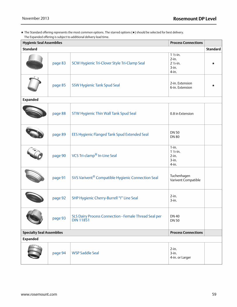
Rosemount DP LevelNovember 2013
59www.rosemount.com
Hygienic Seal Assemblies Process Connections
Standard Standard
page 83 SCW Hygienic Tri-Clover Style Tri-Clamp Seal
1 ½-in.2-in.2 ½-in.3-in.4-in.
★
page 85 SSW Hygienic Tank Spud Seal 2-in. Extension6-in. Extension
★
Expanded
page 88 STW Hygienic Thin Wall Tank Spud Seal 0.8 in Extension
page 89 EES Hygienic Flanged Tank Spud Extended Seal DN 50DN 80
page 90 VCS Tri-clamp® In-Line Seal
1-in.1 ½-in.2-in.3-in.4-in.
page 91 SVS Varivent® Compatible Hygienic Connection Seal Tuchenhagen Varivent Compatible
page 92 SHP Hygienic Cherry-Burrell “I” Line Seal 2-in.3-in.
page 93 SLS Dairy Process Connection - Female Thread Seal per DIN 11851
DN 40DN 50
Specialty Seal Assemblies Process Connections
Expanded
page 94 WSP Saddle Seal 2-in.3-in.4-in. or Larger
★ The Standard offering represents the most common options. The starred options (★) should be selected for best delivery.
__The Expanded offering is subject to additional delivery lead time.

Rosemount DP Level November 2013
page 96 UCP Male Threaded Pipe Mount Seals and PMW Paper Mill Sleeve Seals
1 ½-in. with Threaded Knurled Nut1-in. with Cap Screw Retainer
page 97 CTW Chemical Tee Seal Retro-fit
page 98 TFS Wafer Style In-Line Seal
1-in. / DN 251 ½-in. / DN 402-in. / DN 503-in. / DN 804-in. / DN 100
page 99 WFW Flow-Thru Flanged Seal 1-in.2-in.3-in.
★ The Standard offering represents the most common options. The starred options (★) should be selected for best delivery.
__The Expanded offering is subject to additional delivery lead time.
60 www.rosemount.com

Rosemount DP LevelNovember 2013
Flanged Seals
FFW Flush Flanged Seal
Table 16. FFW Flush Flanged Seal – Ordering Information★ The Standard offering represents the most common options. The starred options (★) should be selected for best delivery.
__The Expanded offering is subject to additional delivery lead time.
Code Industry Standards
Standard Standard
A ANSI/ASME B16.5 (American National Standards Institute/American Society of Mechanical Engineers) ★
D EN 1092-1 (European Standard) ★
T GOST 12815-80 (Russian Standard) ★
Expanded
J JIS B2238 (Japanese Industrial Standard)
Process Connection Style
Standard Standard
FFW Flush Flanged Seal ★
Process Connection Size
ANSI/ASME B16.5 EN 1092-1 / GOST 12815-80 JIS B2238
Standard Standard
G 2-in. DN 50 50 A ★
7 3-in. — 80 A ★
J — DN 80 — ★
9 4-in. DN 100 100 A ★
Flange / Pressure Rating
ANSI/ASME B16.5 EN 1092-1 / GOST 12815-80 JIS B2238
Standard Standard
1 Class 150 — 10K ★
2 Class 300 — 20K ★
4 Class 600 — 40K ★
G — PN 40 — ★
Expanded
E — PN 10 / 16 (DN 100 only) —5 Class 900 — —6 Class 1500 — —7 Class 2500 — —H — PN 63 —J — PN 100 —K — PN 160 —
61www.rosemount.com

Rosemount DP Level November 2013
Diaphragm and Wetted, Upper Housing, Flange Material
Diaphragm and Wetted Upper Housing Flange
Standard Standard
CA(1)(2) 316L SST 316L SST CS ★
DA(2) 316L SST 316L SST 316 SST ★
CB(1)(3) Alloy C-276, seam welded 316L SST CS ★
DB(3) Alloy C-276, seam welded 316L SST 316 SST ★
CC(1) Tantalum, seam welded 316L SST CS ★
DC Tantalum, seam welded 316L SST 316 SST ★
C3(1)(2)(3)(4) Tantalum, brazed 316L SST CS ★
D3(1)(2)(3)(4) Tantalum, brazed 316L SST 316 SST ★
Expanded
MB(1)(2) Alloy C-276, solid faceplate Alloy C-276 / 316L SST CSKB(1)(2) Alloy C-276, solid faceplate Alloy C-276 / 316L SST 316 SSTDJ Alloy B, seam welded 316L SST 316 SSTDF 304L SST, seam welded 316L SST 316 SSTDV Alloy 400, seam welded 316L SST 316 SSTRH(2) (5) Titanium Grade 4 Titanium GR.4 316 SSTDH(6) Titanium Grade 4, seam welded 316L SST 316 SSTDE Alloy 600, seam welded 316L SST 316 SSTDP Nickel 201, seam welded 316L SST 316 SSTWW(2)(7) 316Ti SST (WNr 1.4571) 316Ti SST (WNr 1.4571) 316Ti SST (WNr 1.4571)DZ(6) Zirconium 702, seam welded 316L SST 316 SSTD4 Alloy C-22, seam welded 316L SST 316 SSTD5 Duplex 2507 SST, seam welded 316L SST 316 SST
Flushing Connection Ring Material (Lower Housing)(8)
Standard Standard
0 None ★
A 316L SST ★
B Alloy C-276 ★
Expanded
2 Duplex 2205 SSTH Titanium Grade 46 Nickel 201V Alloy 400
Flushing Connection Options, Quantity (Size)
Standard Standard
0 None ★
1 1 (1/4-18 NPT) ★
3 2 (1/4-18 NPT) ★
7 1 (1/2-14 NPT) ★
9 2 (1/2-14 NPT) ★
Options (Include with selected model number)
Gasket Material
Standard Standard
J PTFE gasket (for use with flushing connection ring) ★
Table 16. FFW Flush Flanged Seal – Ordering Information★ The Standard offering represents the most common options. The starred options (★) should be selected for best delivery.
__The Expanded offering is subject to additional delivery lead time.
62 www.rosemount.com

Rosemount DP LevelNovember 2013
Expanded
N Grafoil gasket (for use with flushing connection ring)K Barium Sulfate filled PTFE gasket (for use with flushing connection ring)
Flushing Plug, Vent/Drain Valve
Standard Standard
D Alloy C-276 plug(s) for flushing connection(s) ★
G 316 SST plug(s) for flushing connection(s) ★
H 316 SST vent/drain for flushing connection(s) ★
Diaphragm Thickness
Expanded
C 0.006-in. (150 μm) available with 316L SST, Alloy C-276, and Duplex 2507 SST for abrasive applications7 0.002-in. (50 μm) available with 316L SST and Alloy C-276
Mounting Flange
Expanded
4(9) Flat face, flush flanged
Code Conformance
Standard Standard
T(10) Wetted Material Compliance per NACE MR 0175/ISO 15156, MR 0103 ★
Gasket Surface Finish
Expanded
1 Gasket Surface Ra 125 Max.
Code Conformance
Standard Standard
B Extra Fill For Cold Temp Application ★
Diaphragm Coating
Expanded
Z(11) 0.0002-in. (5 m) gold plated DiaphragmV(11) PTFE coated diaphragm for nonstick purposes only
Capillary Change
Expanded
2 Radial capillary connection
Alternate Design
Standard Standard
E One Piece Design ★
Typical Model Number: 1199 W DC 1 0 A FFW 7 1 DA 0 0
(1) Only available with two piece design.
(2) For use with spiral wound metallic gaskets.
(3) Not available with option code C.
(4) Only available in Process Connection Size code G, 7, and J.
Table 16. FFW Flush Flanged Seal – Ordering Information★ The Standard offering represents the most common options. The starred options (★) should be selected for best delivery.
__The Expanded offering is subject to additional delivery lead time.
63www.rosemount.com

Rosemount DP Level November 2013
(5) Not available with welded capillary connections or direct mount.
(6) Operating temperature limited to 302 °F (150 °C).
(7) Only available with one-piece design, option code E.
(8) Supplied standard with ThermoTork TN9000.
(9) The mounting flange and upper housing are a single item for the one-piece design. Only available with diaphragm and wetted part material codes DA, DB, DJ, DF, DV, DH, DE, DP, WW, DZ, D4, DC, and D5.
(10) Materials of Construction comply with metallurgical requirements highlighted within NACE MR 0175 / ISO 15156 for sour oil field production environments. Environmental limits apply to certain materials. Consult latest standard for details. Selected materials also conform to NACE MR 0103 for sour refining environments.
(11) Only available on 316LSS, Alloy 400 and Alloy C-276.
64 www.rosemount.com

Rosemount DP LevelNovember 2013
RFW Flanged Seal
Table 17. RFW Flanged Seal Ordering Information★ The Standard offering represents the most common options. The starred options (★) should be selected for best delivery.
__The Expanded offering is subject to additional delivery lead time.
Code Industry Standard
Standard Standard
A ANSI/ASME B16.5 (American National Standards Institute/American Society of Mechanical Engineers) ★
D EN 1092-1 (European Standard) ★
T GOST 12815-80 (Russian Standard) ★
Expanded
J JIS B2238 (Japanese Industrial Standard)
Process Connection Style
Standard Standard
RFW Flanged Seal ★
Process Connection Size
ANSI/ASME B16.5 EN 1092-1 / GOST 12815-80 JIS B2238
Standard Standard
2 1-in. — 25A ★
4 11/2-in. — 40A ★
D — DN 25 — ★
F — DN 40 — ★
Expanded
1 1/2-in. — —A 3/4-in. DN 10 10AB — DN 15 15AC — DN 20 20A
Flange/Pressure Rating
ANSI/ASME B16.5 EN 1092-1 / GOST 12815-80 JIS B2238
Standard Standard
1 Class 150 — 10K ★
2 Class 300 — 20K ★
4 Class 600 — 40K ★
G — PN 40 — ★
Expanded
5 Class 900 — —6 Class 1500 — —7 Class 2500 — —C — PN 6 —H — PN 63 —J — PN 100 —K — PN 160 —
65www.rosemount.com

Rosemount DP Level November 2013
Diaphragm, Upper Housing, Flange Material
Diaphragm Upper Housing Flange
Standard Standard
CA 316L SST 316L SST CS ★
DA 316L SST 316L SST 316 SST ★
CB Alloy C-276 316L SST CS ★
DB Alloy C-276 316L SST 316 SST ★
CC Tantalum 316L SST CS ★
DC Tantalum 316L SST 316 SST ★
Expanded
DF 304L SST 316L SST 316 SSTDJ Alloy B 316L SST 316 SSTDE Alloy 600 316L SST 316 SSTDV Alloy 400 316L SST 316 SSTDP Nickel 201 316L SST 316 SSTDK Alloy 20 316L SST 316 SSTRH(1) Titanium Grade 4 Titanium Grade 4 316 SSTDH Titanium Grade 4 316L SST 316 SSTD4 Alloy C-22 316L SST 316 SSTD5 Duplex 2507 SST 316L SST 316 SSTDZ Zirconium 702 316L SST 316 SST
Flushing Connection Ring Material (Lower Housing)(2)
Standard Standard
A 316L SST ★
B Alloy C-276 ★
D Plated CS ★
Expanded
2 Duplex 2205F 304L SSTH Titanium Grade 4V Alloy 400C Tantalum lined 316L SST (no flushing connection allowed)
Flushing Connection Options, Quantity Size
Standard Standard
5 None ★
1 1 (1/4-18 NPT) ★
3 2 (1/4-18 NPT) ★
Expanded
7 1 (1/2-14 NPT)9 2 (1/2-14 NPT)
Options (Include with selected model number)
Gasket Material
Standard Standard
J PTFE gasket ★
Table 17. RFW Flanged Seal Ordering Information★ The Standard offering represents the most common options. The starred options (★) should be selected for best delivery.
__The Expanded offering is subject to additional delivery lead time.
66 www.rosemount.com

Rosemount DP LevelNovember 2013
Expanded
N Grafoil® gasketK Barium Sulfate filled PTFE gasketR Ethylene Propylene gasket
Flushing Plug, Vent/Drain Valve
Standard Standard
D Alloy C-276 plug(s) for flushing connection(s) ★
G 316 SST plug(s) for flushing connection(s) ★
H 316 SST vent/drain for flushing connection(s) ★
Diaphragm Thickness
Expanded
C 0.006-in. (150 μm) available with 316L SST, Alloy C-276, and Duplex 2507 SST for abrasive applications
Bolt Material
Expanded
3 304 SST Bolts (Only available for Stud Bolt Design)
Standard Standard
T(3) Wetted Material Compliance per NACE MR 0175/ISO 15156, MR 0103 ★
Gasket Surface Finish
Expanded
1 Gasket Surface Ra 125 Max.
Cold Temperature Application
Standard Standard
B Extra Fill For Cold Temp Application ★
Diaphragm Coating
Expanded
Z(4) 0.0002-in. (5 μm) gold plated DiaphragmV(4) PTFE coated diaphragm for nonstick purposes only
Large Diaphragm Size
Expanded
9 4.1-in. (104 mm) Diaphragm Diameter
Typical Model Number: 1199 W DC 1 0 A RFW 2 1 DA A 5
(1) Not available with welded capillary connections or direct mount.
(2) Supplied with C4401 Aramid fiber gasket.
(3) Materials of Construction comply with metallurgical requirements highlighted within NACE MR 0175 / ISO 15156 for sour oil field production environments. Environmental limits apply to certain materials. Consult latest standard for details. Selected materials also conform to NACE MR 0103 for sour refining environments.
(4) Only available on 316LSS, Alloy 400 and Alloy C-276.
Table 17. RFW Flanged Seal Ordering Information★ The Standard offering represents the most common options. The starred options (★) should be selected for best delivery.
__The Expanded offering is subject to additional delivery lead time.
67www.rosemount.com

Rosemount DP Level November 2013
68 www.rosemount.com
EFW Extended Flanged Seal
Table 18. EFW Extended Flanged Seal Ordering Information★ The Standard offering represents the most common options. The starred options (★) should be selected for best delivery.
__The Expanded offering is subject to additional delivery lead time.
Code Industry Standard● = Available— = Unavailable
Standard Standard
A ANSI/ASME B16.5 (American National Standards Institute/American Society of Mechanical Engineers) ★
D EN 1092-1 (European Standard) ★
T GOST 12815-80 (Russian Standard) ★
Expanded
J JIS B2238 (Japanese Industrial Standards)
Process Connection Style
Standard Standard
EFW Extended Flanged Seal ★
Process Connection Size
ANSI/ASME B16.5EN 1092-1 / GOST 12815-80
JIS B2238Extension Diameters
Standard Standard
7 3-in. Schedule 80 DN 80 80A 2.58-in. (66 mm) ★
9 4-in. Schedule 80 DN 100 100A 3.50-in. (89 mm) ★
Expanded
4 11/2-in. DN 40 40A 1.45-in. (37 mm)G 2-in. DN 50 50A 1.90-in. (48 mm)H 3-in. (Headbox) DN 80 (Headbox) — 2.875-in. (73 mm)K 4-in. (Headbox) DN 100 (Headbox) 3.780-in. (96 mm)R 3-in. Schedule 40 DN 80 80A 2.85-in. (73 mm)T 4-in.(Schedule 40) DN 100 100A 3.70-in. (94 mm)
Flange/Pressure Rating
ANSI/ASME B16.5 EN 1092-1 / GOST 12815-80
JIS B2238
Standard Standard
1 Class 150 — 10K ★
2 Class 300 — 20K ★
4 Class 600 — 40K ★
G — PN 40 — ★
Expanded
E — PN 10/16 (DN 100 only) —5 Class 900 — —6 Class 1500 — —7 Class 2500 — —H — PN 63 —J — PN 100 —K — PN 160 —J — PN 100 —K — PN 160 —

Rosemount DP LevelNovember 2013
Diaphragm, Extension and Gasket Surface, Upper Housing, Flange MaterialAvailable with Process Connection Code
Code DiaphragmExtension/Gasket Surface
Upper Housing
Mounting Flange
7 9 4 G H K
Standard Standard
DA 316L SST 316L SST 316L SST 316 SST ● ● ● ● ● ● ★
CA 316L SST 316L SST 316L SST CS ● ● ● ● ● ● ★
DB Alloy C-276 Alloy C-276 316L SST 316 SST ● ● ● ● ● ● ★
CB Alloy C-276 Alloy C-276 316L SST CS ● ● ● ● ● ● ★
Expanded
DM Alloy C-276 316L SST 316L SST 316 SST ● ● ● ● ● ●
DD Tantalum 316L SST 316L SST 316 SST ● ● — — — —
DC(1) Tantalum Tantalum Lined 316L SST 316 SST ● ● — ● — —
D5 Duplex 2507 SST Duplex 2205 SST 316L SST 316 SST ● ● ● ● ● ●
D9 Duplex 2507 SST 316L SST 316L SST 316 SST ● ● ● ● ● ●
Extension Length
ANSI/ASME B16.5 EN 1092-1 / JIS B2238 / GOST 12815-80
Standard Standard
2 2-in. 50 mm ★
4 4-in. 100 mm ★
6 6-in. 150 mm ★
Expanded
8 8-in. 200 mm1 1-in. 25 mm3 3-in. 75 mm5 5-in. 125 mm7 7-in. 175 mm9 9-in. 225 mm
Fractional Extension Length
ANSI/ASME B16.5 EN 1092-1 / JIS B2238 / GOST 12815-80
Standard Standard
0 0-in. 0 mm ★
Options (Include with selected model number)
Diaphragm Thickness
Expanded
C 0.006-in. (150 μm) available with 316L SST, Alloy C-276, and Duplex 2507 SST for abrasive applications
Code Conformance
Standard Standard
T(2) Wetted Material Compliance per NACE MR 0175/ISO 15156, MR 0103 ★
Gasket Surface Finish
Expanded
1 Gasket Surface Ra 125 Max.
Table 18. EFW Extended Flanged Seal Ordering Information★ The Standard offering represents the most common options. The starred options (★) should be selected for best delivery.
__The Expanded offering is subject to additional delivery lead time.
69www.rosemount.com

Rosemount DP Level November 2013
Cold Temperature Application
Standard Standard
B Extra Fill For Cold Temperature Application ★
Diaphragm Coating
Expanded
Z(3) 0.0002-in. (5 μm) Gold plated diaphragmV(3) PTFE coated diaphragm for nonstick purposes only
Typical Model Number: 1199 W DC 1 0 A EFW 7 1 DA 2 0
(1) Requires Gasket Surface Finish Code 1 Gasket Surface Finish Ra 125 Max. Available in extension lengths 2, 4 & 6 in. For all other lengths consult factory.
(2) Materials of Construction comply with metallurgical requirements highlighted within NACE MR 0175 / ISO 15156 for sour oil field production environments. Environmental limits apply to certain materials. Consult latest standard for details. Selected materials also conform to NACE MR 0103 for sour refining environments.
(3) Only available on 316LSS, Alloy 400 and Alloy C-276.
Table 18. EFW Extended Flanged Seal Ordering Information★ The Standard offering represents the most common options. The starred options (★) should be selected for best delivery.
__The Expanded offering is subject to additional delivery lead time.
70 www.rosemount.com

Rosemount DP LevelNovember 2013
PFW Pancake Seal
Table 19. PFW Pancake Seal Ordering Information★ The Standard offering represents the most common options. The starred options (★) should be selected for best delivery.
__The Expanded offering is subject to additional delivery lead time.
Code Industry Standard
Standard Standard
A ANSI/ASME B16.5 (American National Standards Institute/American Society of Mechanical Engineers) ★
D EN 1092-1 (European Standard) ★
T GOST 12815-80 (Russian Standard) ★
Process Connection Style
Standard Standard
PFW Pancake Seal ★
Process Connection Size
ANSI EN 1092-1 / GOST 12815-80
Standard Standard
G 2-in. DN 50 ★
7 3-in. — ★
J — DN 80 ★
Flange/Pressure Rating
ANSI EN 1092-1 / GOST 12815-80
Standard Standard
0 No flange supplied, seal MWP based on customer supplied flange ★
1 Class 150 — ★
2 Class 300 — ★
4 Class 600 — ★
G — PN40 ★
Expanded
5 Class 900 —6 Class 1500 —7 Class 2500 —H — PN 63J — PN 100
Diaphragm and Wetted, Upper Housing, Flange Material
Diaphragm and Wetted Upper Housing Flange
Standard Standard
LA(1) 316L SST 316L SST None ★
CA(1) 316L SST 316L SST CS ★
DA(1) 316L SST 316L SST 316 SST ★
LB Alloy C-276, Seam Welded 316L SST None ★
CB Alloy C-276, Seam Welded 316L SST CS ★
DB Alloy C-276, Seam Welded 316L SST 316 SST ★
LC Tantalum, Seam Welded 316L SST None ★
CC Tantalum, Seam Welded 316L SST CS ★
DC Tantalum, Seam Welded 316L SST 316 SST ★
71www.rosemount.com

Rosemount DP Level November 2013
Flushing Connection Ring Material (Lower Housing)(2)
Standard Standard
0 None ★
A 316L SST ★
B Alloy C-276 ★
Flushing Connection Options, Quantity (Size)
Standard Standard
0 None ★
1 1 (1/2-14 NPT) ★
2 2 (1/2-14 NPT) ★
7 1 (1/2-14 NPT) ★
9 2 (1/2-14 NPT) ★
Options (Include with selected model number)
Gasket Material
Standard Standard
J PTFE gasket ★
Expanded
N Grafoil® gasketK Barium Sulfate filled PTFE gasket
Flushing Plug, Vent/Drain Valve
Standard Standard
D Alloy C-276 plug(s) for flushing connection(s) ★
G 316 SST plug(s) for flushing connection(s) ★
H 316 SST vent/drain for flushing connection(s) ★
Diaphragm Thickness
Expanded
C 0.006-in. (150 μm) available with 316L SST, Alloy C-276, and Duplex 2507 SST for abrasive applications
Code Conformance
Standard Standard
T(3) Wetted Material Compliance per NACE MR 0175/ISO 15156, MR 0103 ★
Gasket Surface Finish
Expanded
1 Gasket Surface Ra 125 Max.
Cold Temperature Application
Standard Standard
B Extra Fill For Cold Temp Application ★
Diaphragm Coating
Expanded
Z(4) 0.0002-in. (5 μm) Gold plated diaphragmV(4) PTFE coated diaphragm for nonstick purposes only
Typical Model Number: 1199 W DC 1 0 A PFW 7 1 DA 0 0
(1) For use with customer supplied spiral wound metallic gaskets.
(2) Supplied standard with Thermo Torque TN9000 gasket.
(3) Materials of Construction comply with metallurgical requirements highlighted within NACE MR 0175 / ISO 15156 for sour oil field production environments. Environmental limits apply to certain materials. Consult latest standard for details. Selected materials also conform to NACE MR 0103 for sour refining environments.
(4) Only available on 316LSST, Alloy 400, and Alloy C-276.
Table 19. PFW Pancake Seal Ordering Information★ The Standard offering represents the most common options. The starred options (★) should be selected for best delivery.
__The Expanded offering is subject to additional delivery lead time.
72 www.rosemount.com

Rosemount DP LevelNovember 2013
FCW Flush Flanged Seal – Ring Type Joint (RTJ) Gasket Surface
Table 20. FCW Flush Flanged Seal – Ring Type Joint (RTJ) Gasket Surface Ordering InformationThis seal is part of the Expanded offering and is subject to additional delivery lead time.
Code Industry Standards
Expanded
A ANSI/ASME B16.5 (American National Standards Institute/American Society of Mechanical Engineers)
Process Connection Style
Expanded
FCW Flush Flanged Seal - Ring Type Joint Gasket Surface
Process Connection Size
Expanded
G 2-in. 7 3-in.
Flange/Pressure Rating
Expanded
1 Class 1502 Class 3004 Class 6005 Class 9006 Class 15007 Class 2500
Diaphragm and Wetted, Upper Housing, Flange Material
Diaphragm and Wetted Upper Housing Flange
Expanded
DA 316L SST 316L SST 316 SSTKB Alloy C-276 316L SST 316 SSTK5 Duplex 2507 SST/Duplex 2205 316L SST 316 SST
Flushing Connection Ring Material (Lower Housing)
Expanded
0 NoneA 316L SSTB Alloy C-2762 Duplex 2205 SST
Flushing Connection Options
Expanded
0 None1 1 (1/4-18 NPT)3 2 (1/4-18 NPT)7 1 (1/2-14 NPT) 9 2 (1/2-14 NPT)
73www.rosemount.com

Rosemount DP Level November 2013
Options (Include with selected model number)
Flushing Plug, Vent/Drain Valve
Expanded
D Alloy C-276 plug(s) for flushing connection(s)G 316 SST plug(s) for flushing connection(s)H 316 SST vent/drain for flushing connection(s)
Diaphragm Thickness
Expanded
C 0.006-in. (150 μm) available with 316L SST, Alloy C-276, and Duplex 2507 SST for abrasive applications7 0.002-in. (50 μm) available with 316L SST and Alloy C-276
Code Conformance
Expanded
T(1) Wetted Material Compliance per NACE MR 0175/ISO 15156, MR 0103
Cold Temp Application
Expanded
B Extra Fill For Cold Temp Application
Diaphragm Coating
Expanded
Z(2) 0.0002-in. (5 μm) Gold plated diaphragmV(2) PTFE coated diaphragm for nonstick purposes only
Alternate Design
Expanded
E One Piece Design
Typical Model Number: 1199 W DC 1 0 A FCW 7 1 DA 0 0
(1) Materials of Construction comply with metallurgical requirements highlighted within NACE MR 0175 / ISO 15156 for sour oil field production environments. Environmental limits apply to certain materials. Consult latest standard for details. Selected materials also conform to NACE MR 0103 for sour refining environments.
(2) Only available on 316LSST and Alloy C-276.
Table 20. FCW Flush Flanged Seal – Ring Type Joint (RTJ) Gasket Surface Ordering InformationThis seal is part of the Expanded offering and is subject to additional delivery lead time.
74 www.rosemount.com

Rosemount DP LevelNovember 2013
RCW Ring Type Joint (RTJ) Flanged Seal
Table 21. RCW Ring Type Joint Flanged Seal Ordering InformationThis seal is part of the Expanded offering and is subject to additional delivery lead time.
Code Industry Standard
Expanded
A ANSI/ASME B16.5 (American National Standards Institute/American Society of Mechanical Engineers)
Process Connection Style
Expanded
RCW Flanged Seal - Ring Type Joint Gasket Surface
Process Connection Size
Expanded
1 1/2-in. (Bolts and studs included for ANSI Class 300 to 1500, not available for ANSI Class 150)A 3/4-in. (Not available for Class 150)2 1-in.4 11/2-in.
Flange/Pressure Rating
Expanded
1 Class 1502 Class 3004 Class 6005 Class 9006 Class 15007 Class 2500
Diaphragm, Upper Housing, Flange Material
Diaphragm Upper Housing Flange
Expanded
DA 316L SST 316L SST 316 SSTDB Alloy C-276 316L SST 316 SSTDC Tantalum 316L SST 316 SSTDE Alloy 600 316L SST 316 SSTDF 304L SST 316L SST 316 SSTDJ Alloy B316L SST 316L SST 316 SSTDV Alloy 400 316L SST 316 SSTDP Nickel 201 316L SST 316 SSTRH Titanium Grade 4 Titanium Grade 4 316 SSTDH(1) Titanium Grade 4 316L SST 316 SSTD4 Alloy 22 316L SST 316 SSTD5 Duplex 2507 SST 316L SST 316 SSTDZ(1) Zirconium 702 316L SST 316 SSTDK Alloy 20 316L SST 316 SST
75www.rosemount.com

Rosemount DP Level November 2013
Flushing Connection Ring Material (Lower Housing)
Expanded
A 316L SSTB Alloy C-276F 304L SSTH Titanium Grade 42 Duplex 2205 SSTV Alloy 400
Flushing Connection Options
Expanded
5 None1 1 (1/4-18 NPT)3 2 (1/4-18 NPT)7 1 (1/2-14 NPT) 9 2 (1/2-14 NPT)
Options (Include with selected model number)
Gasket Material
Expanded
J PTFE gasketN Grafoil® gasketK Barium Sulfate filled PTFE gasketR Ethylene Propylene gasket
Flushing Plug, Vent/Drain Valve
Expanded
D Alloy C-276 plug(s) for flushing connection(s)G 316 SST plug(s) for flushing connection(s)H 316 SST vent/drain for flushing connection(s)
Diaphragm Thickness
Expanded
C 0.006-in. (150 μm) available with 316L SST, Alloy C-276, and Duplex 2507 SST for abrasive applications
Bolt Material (Optional)
Expanded
3 304 SST Bolts (Only available for Stud Bolt Design)
Code Conformance
Expanded
T(2) Wetted Material Compliance per NACE MR 0175/ISO 15156, MR 0103
Cold Temperature Application
Expanded
B Extra Fill For Cold Temp Application
Diaphragm Coating
Expanded
Z(3) 0.0002-in. (5 μm) Gold plated diaphragmV(3) PTFE coated diaphragm for nonstick purposes only
Table 21. RCW Ring Type Joint Flanged Seal Ordering InformationThis seal is part of the Expanded offering and is subject to additional delivery lead time.
76 www.rosemount.com

Rosemount DP LevelNovember 2013
77www.rosemount.com
Large Diaphragm Size
Expanded
9 4.1-in. (104 mm) Diaphragm Diameter
Typical Model Number: 1199 W DC 1 0 A RCW 2 1 DA A 5
(1) Operating temperature is limited to 302 °F (150 °C).
(2) Materials of Construction comply with metallurgical requirements highlighted within NACE MR 0175 / ISO 15156 for sour oil field production environments. Environmental limits apply to certain materials. Consult latest standard for details. Selected materials also conform to NACE MR 0103 for sour refining environments.
(3) Only available on 316LSS, Alloy 400, and Alloy C-276.
Table 21. RCW Ring Type Joint Flanged Seal Ordering InformationThis seal is part of the Expanded offering and is subject to additional delivery lead time.

Rosemount DP Level November 2013
FUW and FVW Flush Flanged Type Seals
Table 22. FUW and FVW Flush Flanged Type Seals – EN Ordering InformationThis seal is part of the Expanded offering is subject to additional delivery lead time.
Code Industry Standard
Expanded
D EN 1092-1 (European Standard)T GOST 12815-80 (Russian Standard)
Process Connection Style
Expanded
FUW Flush Flanged, EN 1092-1 Type D (Groove)FVW Flush Flanged, EN 1092-1 Type C (Tongue)
Process Connection Size
Expanded
G DN 50J DN 80
Flange/Pressure Rating
Expanded
G PN 40
Diaphragm and Wetted, Upper Housing, Flange Material
Diaphragm and Wetted Upper Housing Flange
Expanded
DA(1) 316L SST 316L SST 316 SSTKB(2) Alloy C-276 316L SST 316 SSTDC(1) Tantalum 316L SST 316 SST
Flushing Connection Ring Material (Lower Housing)
Expanded
0 None
Flushing Connection Options, Quantity (Size)
Expanded
0 None
Options (Include with selected model number)
Cold Temperature Application
Expanded
B Extra Fill For Cold Temperature Application
Alternate Design
Expanded
E One Piece Design
Typical Model Number: 1199 W DC 1 0 A FUW J G DA 0 0
(1) Only available with one piece design, option code E.
(2) Only available with two-piece design.
78 www.rosemount.com

Rosemount DP LevelNovember 2013
Threaded Seals
RTW Threaded Seal
Table 23. RTW Threaded Seal Ordering Information★ The Standard offering represents the most common options. The starred options (★) should be selected for best delivery.
__The Expanded offering is subject to additional delivery lead time.
Code Industry Standard
Standard Standard
A ANSI/ASME B1.20.1 (American National Standards Institute/American Society of Mechanical Engineers ★
D EN 10226-1 (European Standard) ★
Process Connection Style
Standard Standard
RTW Threaded (standard thread is female, for male select Option code 9) ★
Process Connection Size
ANSI/ASME B1.20.1 EN 10226-1
Standard Standard
3 1/2-14 NPT — ★
4 3/4-14 NPT — ★
5 1-11.5 NPT — ★
7(1) 11/2-11.5 NPT — ★
Expanded
1 1/4-18 NPT —C — Parallel thread: G1/2A DIN 162882 3/8-18 NPT —6(1) 11/4-11.5 NPT —N — Tapered thread: R1/2 per ISO 7/1
Pressure Rating
ANSI/ASME B1.20.1 EN 10226-1
Standard Standard
0 2500 psi 172 bar ★
Expanded
2(2) 5000 psi 344 bar3(2)(3) 10000 psi —8 1500 psi (4.1-in. (104 mm) diaphragm 103 bar (4.1-in. (104 mm) diaphragm
Diaphragm, Upper Housing, Flange Material
Diaphragm Upper Housing Flange
Standard Standard
CA 316L SST 316L SST CS ★
DA 316L SST 316L SST 316 SST ★
CB Alloy C-276 316L SST CS ★
DB Alloy C-276 316L SST 316 SST ★
CC Tantalum 316L SST CS ★
DC Tantalum 316L SST 316 SST ★
79www.rosemount.com

Rosemount DP Level November 2013
Expanded
DJ Alloy B 316L SST 316 SSTDF 304L SST 316L SST 316 SSTDP Nickel 201 316L SST 316 SSTDV Alloy 400 316L SST 316 SSTRH(4) Titanium Grade 4 Titanium Grade 4 316 SSTDH(5) Titanium Grade 4 316L SST 316 SSTD4 Alloy 22 316L SST 316 SSTD5 Duplex 2507 SST 316L SST 316 SSTDE Alloy 600 316L SST 316 SSTDZ(5) Zirconium 702 316L SST 316 SSTDK Alloy 20 316L SST 316 SSTRZ(4) Zirconium 702 Zirconium 702 316 SST
Flushing Connection Ring Material (Lower Housing)(6)(7)
Standard Standard
A 316L SST ★
B Alloy C-276 ★
Expanded
D Plated Carbon Steel2 Duplex 2205 SSTH Titanium Grade 4V Alloy 400F 304L SST
Flushing Connection Options
Standard Standard
5 None ★
1 1 (1/4-18 NPT) ★
3 2 (1/4-18 NPT) ★
Expanded
7 1 (1/2-14 NPT) 9 2 (1/2-14 NPT)
Options (Include with selected model number)
Gasket Material
Standard Standard
J PTFE gasket (for use with flushing connection ring) ★
N Grafoil® gasket (for use with flushing connection ring) ★
R Ethylene Propylene gasket (for use with flushing connection ring) ★
Expanded
K Barium Sulfate filled PTFE gasket (for use with flushing connection ring)
Flushing Plug, Vent/Drain Valve
Standard Standard
D Alloy C-276 plug(s) for flushing connection(s) ★
G 316 SST plug(s) for flushing connection(s) ★
H 316 SST vent/drain for flushing connection(s) ★
Table 23. RTW Threaded Seal Ordering Information★ The Standard offering represents the most common options. The starred options (★) should be selected for best delivery.
__The Expanded offering is subject to additional delivery lead time.
80 www.rosemount.com

Rosemount DP LevelNovember 2013
Diaphragm Thickness
Expanded
C 0.006-in. (150 μm) available with 316L SST, Alloy C-276, and Duplex 2507 SST for abrasive applications
Bolt Material
Standard Standard
3 304 SST Bolts ★
Expanded
4 316 SST Bolts
Code Conformance
Standard Standard
T(8) Wetted Material Compliance per NACE MR 0175/ISO 15156, MR 0103 ★
Cold Temperature Application
Standard Standard
B Extra Fill For Cold Temp Application ★
Diaphragm Coating
Expanded
Z(9) 0.0002-in. (5 μm) Gold plated diaphragmV(9) PTFE coated diaphragm for nonstick purposes only
Special Threads in Lower Housing
Expanded
9 Male Threads
Typical Model Number: 1199 W DC 1 0 A RTW 3 0 DA A 5
(1) Flushing connection not available.
(2) Consult an Emerson Process Management representative for pricing and availability on Pressure Rating codes 2 or 3.
(3) The following process connection sizes are D rated: 3/4-in (9000 psi/621 bar), 1-in. (8700 psi/600 bar), 11/4-in (7000 psi/483 bar), and 11/2-in. (6000 psi/414 bar).
(4) Not available with welded capillary connections or direct mount.
(5) Operating temperature is limited to 302 °F (150 °C).
(6) Supplied with C4401 aramid fiber gasket.
(7) Flushing Connection Ring/ Lower Housing assembly bolts provided as standard are carbon steel for ANSI and 304 SST for EN.
(8) Materials of Construction comply with metallurgical requirements highlighted within NACE MR 0175 / ISO 15156 for sour oil field production environments. Environmental limits apply to certain materials. Consult latest standard for details. Selected materials also conform to NACE MR 0103 for sour refining environments.
(9) Only available on 316LSS, Alloy 400, and Alloy C-276.
Table 23. RTW Threaded Seal Ordering Information★ The Standard offering represents the most common options. The starred options (★) should be selected for best delivery.
__The Expanded offering is subject to additional delivery lead time.
81www.rosemount.com

Rosemount DP Level November 2013
HTS Male Threaded Seal
Table 24. HTS Male Threaded Seal Ordering InformationThis seal is part of the Expanded offering and is subject to additional delivery lead time.
Code Industry Standard
Expanded
A ANSI/ASME B1.20.1 (American National Standards Institute/American Society of Mechanical Engineers)D EN 10226-1 (European Standard)
Process Connection Style
Expanded
HTS Male Threaded Seal
Process Connection Size, Pressure Rating
ANSI/ASME B1.20.1 EN 10226-1
Expanded
5A(1) 1-11,5 NPT, 8700 psi (600 bar) —7A(2) 1½-11,5 NPT, 6000 psi (414 bar) —9A (3) 2-11,5 NPT, 4000 psi (276 bar) —EA(1) — G1, 455 bar (6600 psi)GA(2) — G11/2, BSP, 400 bar (5801 psi)JA(3) — G2, BSP, 280 bar (4060 psi)
Diaphragm and Wetted, Upper Housing Material
Diaphragm and Wetted Upper Housing
Expanded
LA00 316L SST 316L SST
Typical Model Number: 1199 W DC 1 0 A HTS 7 A LA 0 0
(1) Consult factory for calibrated spans lower than 300 psi (21 bar).
(2) Consult factory for calibrated spans lower than 100 psi (7 bar).
(3) Consult factory for calibrated spans lower than 50 psi (3,4 bar).
82 www.rosemount.com

Rosemount DP LevelNovember 2013
Hygienic seals
SCW Hygienic Tri-Clover Style Tri-Clamp Seal
Table 25. SCW Hygienic Tri-Clover Style Tri-Clamp Seal Ordering Information★ The Standard offering represents the most common options. The starred options (★) should be selected for best delivery.
__The Expanded offering is subject to additional delivery lead time.
Industry Standard
Standard Standard
S Hygienic Seal (Conforms to 3-A Standard 74-03) ★
Process Connection Style
Standard Standard
SCW(1) Tri-Clover Style Tri-Clamp Seal ★
Process Connection Size
Standard Standard
30(2) 1½-in. ★
50(3) 2-in. ★
70 3-in. ★
Expanded
60 2½-in.90 4-in.
Diaphragm and Wetted, Upper Housing Material
Diaphragm and Wetted Upper Housing
Standard Standard
LA00 316L SST 316L SST ★
Expanded
LB00 Alloy C-276 316L SST
Options (Include with selected model number)
Surface Finish
Expanded
D 10 in. (0.25 m) Ra surface finishG 15 in. (0.375 m) Ra surface finishH 20 in. (0.50 m) Ra surface finish
Non-Hygienic Fill Fluid
Expanded
P Non-Hygienic fill fluid (does not conform to 3-A Standard 74)
Clamp and Gasket Material
Expanded
2 High-Pressure Ladish Clamp & Nitrile butadiene (NBR) gasket3(4) Nitrile butadiene (NBR) gasket
83www.rosemount.com

Rosemount DP Level November 2013
Polishing
Expanded
6 Electro polishing
Typical Model Number: 1199 W NC 1 0 S SCW 7 0 LA 0 0
(1) Clamp and gasket furnished by user. The maximum working pressure is dependent upon the clamp pressure rating.
(2) Consult factory for calibrated spans lower than 15 psi (1034 mbar). Rosemount 1199 Remote Seal Minimum Span Summary calls out a minimum span of 1000 inH2O or 2490 mbar for 1-1/2“SSCW
(3) Consult factory for calibrated spans lower than 5 psi (345 mbar). Rosemount 1199 Remote Seal Minimum Span Summary calls out a minimum span of 150 inH2O or 373 mbar for 2” SSCW
(4) See Table 26 below.
Table 26. High Pressure Ladish Clamp Maximum Working Pressure
Process connection size 70 °F (21 °C) 250 °F (121 °C)
1 1/2-in. 1,500 psi (103 bar) 1,200 psi (83 bar)2-in. 1,000 psi (69 bar) 800 psi (55 bar)2 1/2-in. 1,000 psi (69 bar) 800 psi (55 bar)3-in. 1,000 psi (69 bar) 800 psi (55 bar)4-in. 1,000 psi (69 bar) 800 psi (55 bar)
Table 25. SCW Hygienic Tri-Clover Style Tri-Clamp Seal Ordering Information★ The Standard offering represents the most common options. The starred options (★) should be selected for best delivery.
__The Expanded offering is subject to additional delivery lead time.
84 www.rosemount.com

Rosemount DP LevelNovember 2013
SSW Hygienic Tank Spud Seal
Table 27. SSW Hygienic Tank Spud Seal Ordering Information★ The Standard offering represents the most common options. The starred options (★) should be selected for best delivery.
__The Expanded offering is subject to additional delivery lead time.
Code Industry Standard
Standard Standard
S Hygienic Seal (Conforms to 3-A Standard 74-03) ★
Process Connection Style
Standard Standard
SSW(1) Tank Spud Seal ★
Process Connection Size, Pressure Rating
Standard Standard
A0 600 psi (41 bar) ★
Upper Housing
Standard Standard
A 316L SST ★
Diaphragm and Wetted, Extension Material
Diaphragm and Wetted Extension
Standard Standard
AL 316L SST(2) 316L SST(2) ★
Expanded
BB Alloy C-276 316L SST ★
Extension Length
Standard Standard
2 2-in. ★
6 6-in. ★
Options (Include with selected model number)
Surface Finish
Expanded
G(3) 15 in. (0.375 m) diaphragm surface finishH 20 in(0.5 m) diaphragm surface finish
Diaphragm Thickness
Expanded
C 0.006-in. (150 m)
Tank Spud
Standard Standard
1 Tank Spud Included with Shipment ★
Non-Hygienic Fill Fluid
Expanded
P Non-Hygienic fill fluid (Does not conform to 3-A Standard 74)
85www.rosemount.com

Rosemount DP Level November 2013
Sanitary Tank Spud accessories
Non-Hygienic Fill Fluid
Expanded
3Nitrile butadiene (NBR) O-ring instead of Standard Ethylene Propylene O-ring (Conforms to 3-A Standard 74)
4Fluorocarbon (FMK)® O-ring, instead of Standard Ethylene Propylene O-ring (Conforms to 3-A Standard 74)
Polishing
Expanded
6 Electro polishing
Typical Model Number: 1199 W NC 1 0 S SSW A 0 AA L 2
(1) Clamp and Ethylene Propylene o-ring (conforms to 3-A standard 74 and USP class VI) supplied.
(2) Diaphragm brazed and TIG-welded to extension.
(3) Requires Option code 6, Electro polishing.
Table 27. SSW Hygienic Tank Spud Seal Ordering Information★ The Standard offering represents the most common options. The starred options (★) should be selected for best delivery.
__The Expanded offering is subject to additional delivery lead time.
Tank Spud and Clamp
Rosemount 3051S with Direct Mount Sanitary Tank Spud with Clamp
86 www.rosemount.com

Rosemount DP LevelNovember 2013
Tank Spud Tank Spud Plug
Dimensions are in inches (millimeters)
Table 28. Sanitary Tank Spud Optional Accessories
Model Description
01199-0061-0001 2 in. Sanitary Tank Spud(1)
01199-0061-0002 6 in. Sanitary Tank Spud(1)
(1) Welding procedures and material certifications are shipped with the tank spud. Standard material is cast equivalent of 316L SST per ASTM- A351 grade CF3M.
Table 29. Sanitary Tank Spud Spare Parts
Part Number Description
01199-0526-0002 ClampC53185-0070-0341 Ethylene Propylene O-ring
Tank Spud and Clamp
0.50(13)
0.09(2)
A
20° ± 1°
0.19 (5)
5.98(152)
5.22(133)
3.70(94)
R
37-01
74
1.10(28)
20°
A
5.22(133)
3.63(92)
3.93(100)
87www.rosemount.com

Rosemount DP Level November 2013
STW Hygienic Thin Wall Tank Spud Seal
Table 30. STW Hygienic Thin Wall Tank Spud Seal Ordering InformationThis seal is part of the Expanded offering and is subject to additional delivery lead time.
Code Industry Standard
Expanded
S Hygienic Seal (Conforms to 3-A Standard 74-03)
Process Connection Style
Expanded
STW(1) Thin Wall Tank Spud Seal
Process Connection Size, Pressure Rating
Expanded
B0 4-in. Tri-Clamp, 600 psi (41 bar)
Diaphragm and Wetted, Extension Material
Diaphragm and Wetted Extension
Expanded
LA00 316L SST 316L SSTBB00 Alloy C-276 Alloy C-276
Options (Include with selected model number)
Surface Finish
Expanded
G(2) 15 in. (0.375 m) diaphragm surface finishH 20 in(0.5 m) diaphragm surface finish
Non-Hygienic Fill Fluid
Expanded
P Non-Hygienic fill fluid (Does not conform to 3-A Standard 74)
Polishing
Expanded
6 Electro polishing
Typical Model Number: 1199 W NC 1 0 S STW B 0 LA 0 0
(1) For tank walls up to 3/16-in. thick. Clamp and Ethylene Propylene o-ring supplied.
(2) Requires Option code 6, Electro polishing.
88 www.rosemount.com

Rosemount DP LevelNovember 2013
EES Hygienic Flanged Tank Spud Extended Seal
Table 31. EES Hygienic Flanged Tank Spud Extended Seal Ordering InformationThis seal is part of the Expanded offering and is subject to additional delivery lead time.
Code Industry Standard
Expanded
S Hygienic Seal (Conforms to 3-A Standard 74-03)
Process Connection Style
Expanded
EES Flanged Tank Spud Seal
Process Connection Size, Pressure Rating
Expanded
GG DN 50, PN 40JG DN 80, PN 40
Diaphragm and Wetted, Extension Material
Diaphragm and Wetted Extension
Expanded
LA 316L SST 316L SSTLB Alloy C-276 316L SST
Extension Length(1)
Expanded
10 25 mm (1-in.)
Options (Include with selected model number)
Surface Finish
Expanded
G(2) 15 μ-in. (0.375 μm) Ra surface finishH 20 μ-in. (0.50 μm) Ra surface finish
Gasket Material
Expanded
1 Fluorocarbon (FMK) O-ring, instead of Standard Ethylene Propylene O-ring (Conforms to 3-A Standard 74)
Cold Temperature Application
Expanded
B Extra Fill For Cold Temperature Application
Polishing
Expanded
6 Electro polishing
Typical Model Number: 1199 W NC 1 0 S EES J G LA 1 0
(1) Other extension lengths are available upon request.
(2) Requires Option code 6, Electro polishing.
89www.rosemount.com

Rosemount DP Level November 2013
VCS Tri-clamp® In-Line Seal
Table 32. VCS Tri-Clamp In-Line Seal Ordering InformationThis seal is part of the Expanded offering and is subject to additional delivery lead time.
Code Industry Standard
Expanded
S Hygienic Seal (Conforms to 3-A Standard 74-03)
Process Connection Style
Expanded
VCS(1) In-Line Tri-Clover Style Tri-Clamp Seal
Process Connection Size
Expanded
20(2) 1-in.30(3) 1½-in.50 2-in.70 3-in.90 4-in.
Diaphragm and Wetted, Upper Housing Material
Diaphragm and Wetted Upper Housing
Expanded
LA00 316L SST 316L SST
Options (Include with selected model number)
Surface Finish
Expanded
G(4) 15 -in. (0.375 m) Ra surface finishH 20 μ-in. (0.50 μm) Ra surface finish
Non-Hygienic Fill Fluid
Expanded
P Non-Hygienic fill fluid (does not conform to 3-A Standard 74)
Polishing
Expanded
6 Electro polishing
Typical Model Number: 1199 W NC 1 0 S VCS 7 0 LA 0 0
(1) Gasket and clamp are furnished by the user. The maximum working pressure is dependent upon the clamp pressure rating.
(2) Consult factory for calibrated spans lower than 15 psi (1034 mbar).
(3) Consult factory for calibrated spans lower than 5 psi (345 mbar).
(4) Requires Option code 6, Electro polishing.
90 www.rosemount.com

Rosemount DP LevelNovember 2013
SVS Varivent® Compatible Hygienic Connection Seal
Table 33. SVS Varivent® Compatible Hygienic Connection Seal Ordering InformationThis seal is part of the Expanded offering and is subject to additional delivery lead time.
Code Industry Standard
Expanded
S Hygienic Seal (Conforms to 3-A Standard 74-03)
Process Connection Style
Expanded
SVS Tuchenhagen Varivent Compatible Seal
Process Connection Size
Expanded
V0(1) Varivent® Type N DN 40-162
Diaphragm and Wetted, Upper Housing Material
Diaphragm and Wetted Upper Housing
Expanded
LA00 316L SST 316L SST
Options (Include with selected model number)
Non-Hygienic Fill Fluid
Expanded
P Non-Hygienic fill fluid (does not conform to 3-A Standard 74)
Cold Temperature Application
Expanded
B Extra Fill For Cold Temperature Application
Polishing
Expanded
6 Electro polishing
Typical Model Number: 1199 W NC 1 0 S SVS V 0 LA 0 0
(1) Consult factory for calibrated spans lower than 15 psi (1034 mbar). Rosemount 1199 Remote Seal Minimum Span Summary calls out a minimum span of 150 inH2O or 373 mbar not 15 psi or 1034 mbar.
91www.rosemount.com

Rosemount DP Level November 2013
SHP Hygienic Cherry-Burrell “I” Line Seal
Table 34. SHP Hygienic Cherry-Burrell “I” Line Seal Ordering InformationThis seal is part of the Expanded offering and is subject to additional delivery lead time.
Code Industry Standard
Expanded
S Hygienic Seal (Conforms to 3-A Standard 74-03)
Process Connection Style
Expanded
SHP(1) Cherry-Burrell “I” Line Style Seal
Process Connection Size
Expanded
50(2) 2-in. 70 3-in.
Diaphragm and Wetted, Upper Housing Material
Diaphragm and Wetted Upper Housing
Expanded
AA00 316L SST 316L SST
Options (Include with selected model number)
Non-Hygienic Fill Fluid
Expanded
P Non-Hygienic fill fluid (does not conform to 3-A Standard 74)
Typical Model Number: 1199 W NC 1 0 S SHP 7 0 AA 0 0
(1) Clamp and gasket furnished by user. Maximum working pressure is the lesser of either clamp pressure rating or 500 psi.
(2) Consult factory for calibrated spans lower than 5 psi (345 mbar).
92 www.rosemount.com
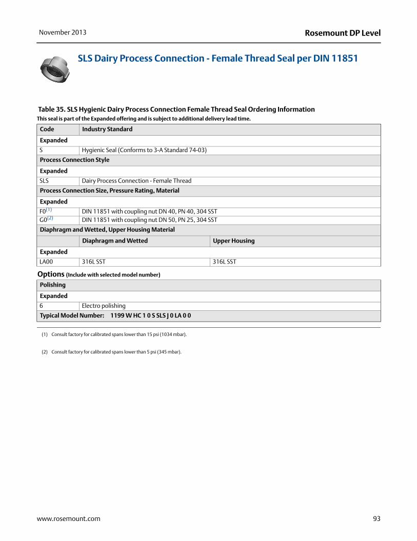
Rosemount DP LevelNovember 2013
SLS Dairy Process Connection - Female Thread Seal per DIN 11851
Table 35. SLS Hygienic Dairy Process Connection Female Thread Seal Ordering InformationThis seal is part of the Expanded offering and is subject to additional delivery lead time.
Code Industry Standard
Expanded
S Hygienic Seal (Conforms to 3-A Standard 74-03)
Process Connection Style
Expanded
SLS Dairy Process Connection - Female Thread
Process Connection Size, Pressure Rating, Material
Expanded
F0(1)
(1) Consult factory for calibrated spans lower than 15 psi (1034 mbar).
DIN 11851 with coupling nut DN 40, PN 40, 304 SSTG0(2)
(2) Consult factory for calibrated spans lower than 5 psi (345 mbar).
DIN 11851 with coupling nut DN 50, PN 25, 304 SST
Diaphragm and Wetted, Upper Housing Material
Diaphragm and Wetted Upper Housing
Expanded
LA00 316L SST 316L SST
Options (Include with selected model number)
Polishing
Expanded
6 Electro polishing
Typical Model Number: 1199 W HC 1 0 S SLS J 0 LA 0 0
93www.rosemount.com

Rosemount DP Level November 2013
Specialty Seals
WSP Saddle Seal
Table 36. WSP Saddle Seal Ordering InformationThis seal is part of the Expanded offering and is subject to additional delivery lead time.
Code Industry Standard
Expanded
N Non-Industry Standard
Process Connection Style
Expanded
WSP Saddle Seal
Process Connection Size
Expanded
G 2-in. Pipe size7 3-in. Pipe size9 4-in. or larger Pipe size
Pressure Rating
Expanded
1 1500 psig at 100 °F (103 bar at 38 °C); eight bolt holes0 1250 psig at 100 °F (86 bar at 38 °C); six bolt holes
Diaphragm, Upper Housing Material
Diaphragm Upper Housing
Expanded
LA 316L SST 316L SSTLB Alloy C-276 316L SSTLC Tantalum 316L SST
Lower Housing Material(1)(2)
Expanded
00 NoneL5 316L SSTB5 Alloy C-276D5 Plated Carbon Steel
Options (Include with selected model number)
Gasket Material
Expanded
J PTFE gasketN Grafoil® gasket
Code Conformance
Expanded
T(3) Wetted Material Compliance per NACE MR 0175/ISO 15156, MR 0103
Diaphragm Coating
Expanded
V PTFE Coated Diaphragm for nonstick purposes (316L SST and Alloy C-276 diaphragms only)
Typical Model Number: 1199 W DC 1 0 N WSP 7 1 LA L N
94 www.rosemount.com

Rosemount DP LevelNovember 2013
(1) Standard pipe schedule 40/40S, for other pipe schedules consult the factory.
(2) Supplied with C4401 Aramid fiber gasket.
(3) Materials of Construction comply with metallurgical requirements highlighted within NACE MR 0175 / ISO 15156 for sour oil field production environments. Environmental limits apply to certain materials. Consult latest standard for details. Selected materials also conform to NACE MR 0103 for sour refining environments.
95www.rosemount.com

Rosemount DP Level November 2013
UCP Male Threaded Pipe Mount Seals and PMW Paper Mill Sleeve Seals
Table 37. UCP and PMW Threaded Pipe Mount Seal Ordering InformationThis seal is part of the Expanded offering and is subject to additional delivery lead time.
Industry Standard
Expanded
N Non-Industry Standard
Process Connection Style
Expanded
UCP Male Threaded Pipe Mount SealPMW Paper Mill Sleeve
Process Connection Size, Pressure Rating
Expanded
30(1) 11/2-in., Threaded Knurled Nut, 600 psi at 100 °F (41 bar at 38 °C) (UCP only)50(2) 1-in., Cap Screw Retainer, 300 psi at 100 °F (21 bar at 38 °C) (PMW only)
Diaphragm and Wetted, Upper Housing Material
Diaphragm and Wetted Upper Housing
Expanded
AA 316L SST 316L SSTBB Alloy C-276 Alloy C-276
Lower Housing Material
Expanded
00 NoneA0 316L SSTB0 Alloy C-276
Options (Include with selected model number)
Diaphragm Coating
Expanded
V PTFE coated diaphragm for nonstick purposes only
Typical Model Number: 1199 W DC 1 0 N UCP 3 0 AA A 0
(1) Only available with UCP process connection size. Consult factory for calibrated spans lower than 50 psi (3,4 bar).
(2) Only available with PMW process connection size. Consult factory for calibrated spans lower than 100 psi (6,9 bar).
96 www.rosemount.com

Rosemount DP LevelNovember 2013
CTW Chemical Tee Seal
Table 38. CTW Chemical Tee Seal Ordering InformationThis seal is part of the Expanded offering and is subject to additional delivery lead time.
Code Industry Standard
Expanded
N Non-Industry Standard
Process Connection Style
Expanded
CTW Chemical Tee Seal
Maximum Working Pressure (Flange Rating)
Expanded
20 300 psi (21 bar)
Diaphragm and Wetted, Upper Housing Material
Diaphragm and Wetted Upper Housing
Expanded
AA 316L SST 316L SSTBB Alloy C-276 Alloy C-276
Lower Housing
Expanded
00 None
Options (Include with selected model number)
Code Conformance
Expanded
T(1) Wetted Material Compliance per NACE MR 0175/ISO 15156, MR 0103
Diaphragm Coating
Expanded
V PTFE coated diaphragm for nonstick purposes only
Typical Model Number: 1199 W NC 1 0 N CTW 2 0 AA 0 0
(1) Materials of Construction comply with metallurgical requirements highlighted within NACE MR 0175 / ISO 15156 for sour oil field production environments. Environmental limits apply to certain materials. Consult latest standard for details. Selected materials also conform to NACE MR 0103 for sour refining environments.
97www.rosemount.com
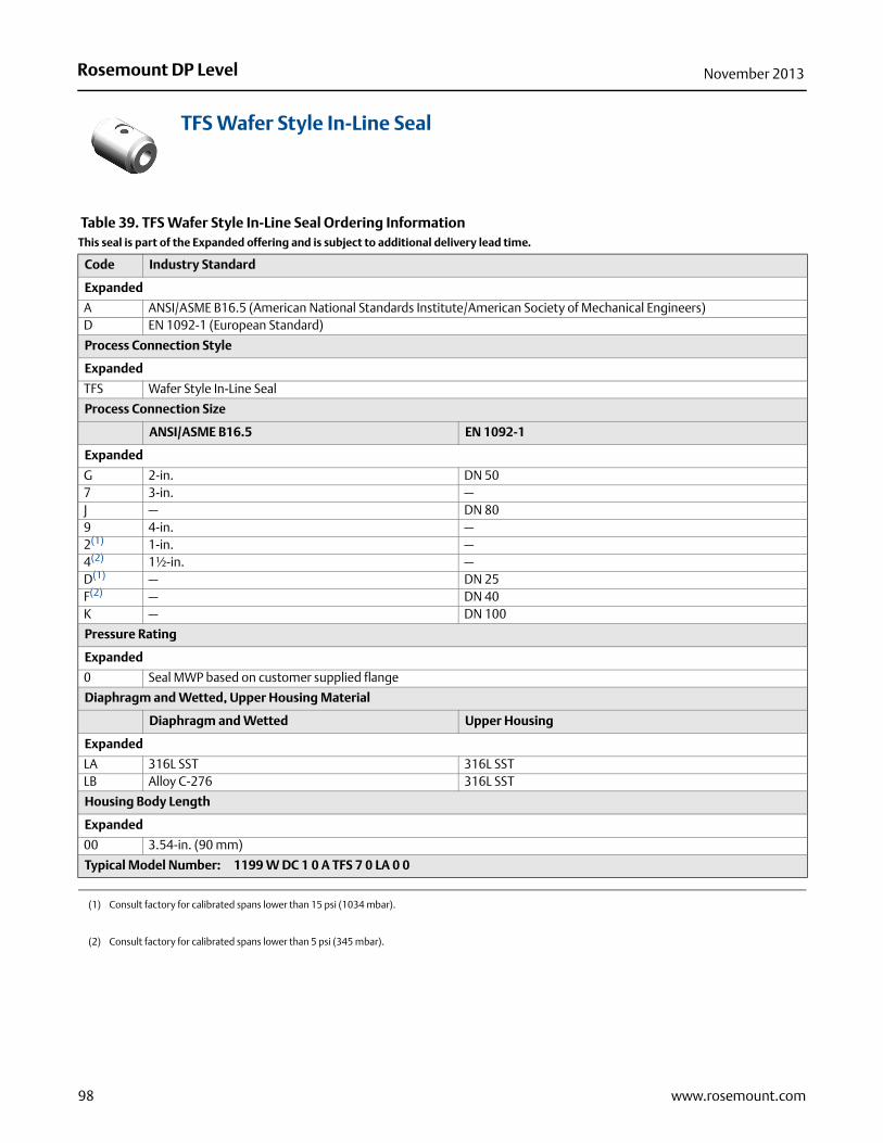
Rosemount DP Level November 2013
TFS Wafer Style In-Line Seal
Table 39. TFS Wafer Style In-Line Seal Ordering InformationThis seal is part of the Expanded offering and is subject to additional delivery lead time.
Code Industry Standard
Expanded
A ANSI/ASME B16.5 (American National Standards Institute/American Society of Mechanical Engineers)D EN 1092-1 (European Standard)
Process Connection Style
Expanded
TFS Wafer Style In-Line Seal
Process Connection Size
ANSI/ASME B16.5 EN 1092-1
Expanded
G 2-in. DN 507 3-in. —J — DN 809 4-in. —2(1) 1-in. —4(2) 1½-in. —D(1) — DN 25F(2) — DN 40K — DN 100
Pressure Rating
Expanded
0 Seal MWP based on customer supplied flange
Diaphragm and Wetted, Upper Housing Material
Diaphragm and Wetted Upper Housing
Expanded
LA 316L SST 316L SSTLB Alloy C-276 316L SST
Housing Body Length
Expanded
00 3.54-in. (90 mm)
Typical Model Number: 1199 W DC 1 0 A TFS 7 0 LA 0 0
(1) Consult factory for calibrated spans lower than 15 psi (1034 mbar).
(2) Consult factory for calibrated spans lower than 5 psi (345 mbar).
98 www.rosemount.com
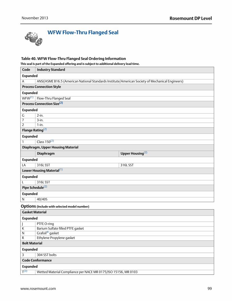
Rosemount DP LevelNovember 2013
WFW Flow-Thru Flanged Seal
Table 40. WFW Flow-Thru Flanged Seal Ordering InformationThis seal is part of the Expanded offering and is subject to additional delivery lead time.
Code Industry Standard
Expanded
A ANSI/ASME B16.5 (American National Standards Institute/American Society of Mechanical Engineers)
Process Connection Style
Expanded
WFW(1) Flow-Thru Flanged Seal
Process Connection Size(2)
Expanded
G 2-in.7 3-in.2 1-in.
Flange Rating(2)
Expanded
1 Class 150(2)
Diaphragm, Upper Housing Material
Diaphragm Upper Housing(2)
Expanded
LA 316L SST 316L SST
Lower Housing Material(1)
Expanded
L 316L SST
Pipe Schedule(2)
Expanded
N 40/40S
Options (Include with selected model number)
Gasket Material
Expanded
J PTFE O-ringK Barium Sulfate filled PTFE gasketN Grafoil® gasketR Ethylene Propylene gasket
Bolt Material
Expanded
3 304 SST bolts
Code Conformance
Expanded
T(3) Wetted Material Compliance per NACE MR 0175/ISO 15156, MR 0103
99www.rosemount.com

Rosemount DP Level November 2013
100 www.rosemount.com
Cold Temperature Application
Expanded
B Extra Fill For Cold Temperature Application
Typical Model Number: 1199 W DC 1 0 A WFW 7 1 LA L N
(1) Supplied with C4401 Aramid fiber gasket.
(2) Consult factory for special process connection sizes, flange pressure ratings, diaphragm/lower housing materials, and pipe schedules.
(3) Materials of Construction comply with metallurgical requirements highlighted within NACE MR 0175 / ISO 15156 for sour oil field production environments. Environmental limits apply to certain materials. Consult latest standard for details. Selected materials also conform to NACE MR 0103 for sour refining environments.
Table 40. WFW Flow-Thru Flanged Seal Ordering InformationThis seal is part of the Expanded offering and is subject to additional delivery lead time.

Rosemount DP LevelNovember 2013
Specifications
Liquid Level Transmitter specifications
Performance specificationsFor zero-based spans, reference conditions, silicone oil fill, glass-filled PTFE O-rings, SST materials, Coplanar flange (3051SMV, 3051S_C) or 1/2-in.- 14 NPT (3051S_T) process connections, digital trim values set to equal range points.
Conformance to specification (±3 (Sigma))
Technology leadership, advanced manufacturing techniques, and statistical process control ensure measurement specification conformance to ±3or better.
Reference accuracy(1)
Stated reference accuracy equations include terminal based linearity, hysteresis, and repeatability, but does not include analog output reference accuracy of ±0.005% of span. For FOUNDATION™ fieldbus and wireless devices, use calibrated range in place of span.
(1) Stated reference accuracy equations include terminal based linearity, hysteresis, and repeatability, but does not include analog only reference accuracy of ±0.005% of span.
3051SAM(2)
(2) For the Rosemount 3051S with 1199 assemble to codes B11 & B12 and 3051SAM with 1199 assemble to code B11 a. Use ±0.55% of span for Ultra and ±0.65% of span for Classic
Ultra±0.025% of Span For spans less than 10:1,±(0.005% URL + 0.015% span)
Classic±0.035% of Span.For spans less than 10:1,±(0.005% URL + 0.015% span)
3051SAL_C
Ultra±0.055% of Span.For spans less than 10:1,±(0.005% URL + 0.015% span)
Classic±0.065% of Span.For spans less than 10:1,±(0.005% URL + 0.015% span)
3051L±0.075% of Span.For spans less than 10:1, ±(0.005% URL + 0.025% span)
2051L±0.075% of Span.For spans less than 10:1, ±(0.005% URL + 0.025% span)
DP Reference Accuracy of 3051S ERS System
Two Coplanar Gage Sensors (3051SAM_ _G)
Ultra Classic
Ranges 2-4 ±0.035% of DP span ±0.049% of DP spanRange 5 ±0.071% of DP span ±0.092% of DP span
Two Coplanar (3051SAM_ _A)
Ultra Classic
Ranges 1-4 ±0.035% of DP span ±0.049% of DP span
Two In-Line Gage Sensors (3051SAM_ _T)Two In-Line Absolute Sensors (3051SAM_ _E)
Ultra Classic
Ranges 1-4 ±0.035% of DP span ±0.049% of DP span
Two Liquid Level Sensors (3051SAL)
Ultra Classic
Ranges 1-5 ±0.055% of DP span ±0.092% of DP span
101www.rosemount.com

Rosemount DP Level November 2013
Warranty(1)
Dynamic performance
Rosemount Level Transmitters - 3051SAL_C, 3051L, and 2051L models - have an 4 - 20 mA HART (1 - 5 Vdc HART Low Power) update rate of 22 updates per second. Electronic Remote Sensor Systems - 3051SAM, 3051SAL_P, and 3051SAL_S models - have an 4 - 20 mA HART (1 - 5 Vdc HART Low Power) update rate of 11 updates per second. See page 94 for WirelessHART update rates.For total response time see Instrument Toolkit®.
Ambient temperature effect
See Instrument Toolkit.
Mounting position effects
With liquid level remote mount seal in vertical plane, zero shift of up to ±1 inH2O (2,49 mbar); with remote mount seal in horizontal plane, zero shift of up to ±5 inH2O (12,45 mbar) plus extension length on extended units; all zero shifts can be zeroed; no span effect.
Vibration Effect
Power Supply Effect
Less than ±0.005% of calibrated span per volt.
Models(1) Ultra Classic
3051SAM and 3051SAL 12-year limited warranty(2) 1-year limited warranty(3)
(1) Warranty details can be found in Emerson Process Management Terms and Conditions of Sale, Document 63445, Rev G (10/06).
(2) Rosemount Ultra and Ultra for Flow transmitter have a limited warranty of twelve (12) years from date of shipment. All other provisions of Emerson Process Management standard limited warranty remains the same.
(3) Goods are warranted for twelve (12) months from the date of initial installation or eighteen (18) months from the date of shipment by seller, whichever period expires first.
3051SAM3051SAL
Less than ±0.1% of URL when tested per the requirements of IEC60770-1 field or pipeline with high vibration level (10-60 Hz 0.21mm displacement peak amplitude / 60-2000 Hz 3g).
For Housing Style codes 1J, 1K, 1L, 2J, and 2M:Less than ±0.1% of URL when tested per the requirements of IEC60770-1 field with general application or pipeline with low vibration level (10-60 Hz 0.15mm displacement peak amplitude / 60-500 Hz 2g).
3051LMeasurement effect due to vibrations is negligible except at resonance frequencies. When at resonance frequencies, vibration effect is less than ±0.1% of URL per g when tested between 15 and 2000 Hz in any axis relative to pipe-mounted process conditions.
2051LLess than ±0.1% of URL when tested per the requirements of IEC60770-1 field or pipeline with high vibration level (10-60 Hz 0.21mm displacement peak amplitude / 60-2000 Hz 3g).
102 www.rosemount.com

Rosemount DP LevelNovember 2013
(1)
,62 bar),49 bar)
,7 bar)7,9 bar)
Electromagnetic Compatibility (EMC)
Transient protection (Option T1)
Functional Specifications
Range and Sensor Limits
Meets all relevant requirements of EN 61326 and NAMUR NE-21.(1)
(1) NAMUR NE-21 does not apply to wireless output code X or ERS configurations.
3051SAM3051SAL
Meets IEEE C62.41.2-2002, Location Category B6 kV crest (0.5 s - 100 kHz)3 kA crest (8 × 20 microseconds)6 kV crest (1.2 × 50 microseconds)
3051L
Meets IEEE C62.41, Category B6 kV crest (0.5 s - 100 kHz)3 kV crest (8 × 20 microseconds)6 kV crest (1.2 × 50 microseconds)
2051L
Meets IEEE C62.41, Category Location B6 kV crest (0.5 s - 100 kHz)3 kV crest (8 × 20 microseconds)6 kV crest (1.2 × 50 microseconds)
Table 41. 3051SAM_ _G, 3051SAL_ _D, 3051SAL_ _G Range and Sensor Limits
Ran
ge Minimum Span Range Limits
Ultra Classic Upper (URL)Lower (LRL)
3051SAL_G(1)(2) 3051SAL_D
2 1.3 inH2O (3,11 mbar) 2.5 inH2O (6,23 mbar) 250.0 inH2O (0,62 bar) -250.0 inH2O (-0,62 bar) -250.0 inH2O (-03 5.0 inH2O (12,4 mbar) 10.0 inH2O (24,9 mbar) 1000.0 inH2O (2,49 bar) -393.0 inH2O (-979 mbar) -1000.0 inH2O (-24 1.5 psi (103,4 mbar) 3.0 psi (206,8 mbar) 300.0 psi (20,7 bar) -14.2 psig (-979 mbar) -300.0 psi (-205 10.0 psi (689,5 mbar) 20.0 psi (1,38 bar) 2000.0 psi (137,9 bar) -14.2 psig (-979 mbar) - 2000.0 psi (-13
(1) When specifying a 3051SAL Ultra, use Classic minimum span.
(2) Assumes atmospheric pressure of 14.7 psig (1 bar).
Table 42. 3051SAM_ _A, 3051SAL_ _A Range and Sensor Limits(1)
Ran
ge Minimum Span Range and Sensor Limits
Upper (URL) Lower (LRL)Ultra Classic
1 0.3 psia (20,7 mbar) 0.3 psia (20,7 mbar) 30 psia (2,07 bar) 0 psia (0 bar) 2 0.75 psia (51,7 mbar) 1.5 psia (0,103 bar) 150 psia (10,34 bar) 0 psia (0 bar) 3 4 psia (275,8 mbar) 8 psia (0,55 bar) 800 psia (55,16 bar) 0 psia (0 bar) 4 20 psia (1,38 bar) 40 psia (2,76 bar) 4000 psia (275,8 bar) 0 psia (0 bar)
(1) When specifying a 3051SAL Ultra, use Classic minimum span.
103www.rosemount.com

Rosemount DP Level November 2013
Table 43. 3051SAM_ _T, 3051SAM_ _E, 3051SAL_ _T, 3051SAL_ _E Range and Sensor LimitsR
ang
e Minimum Span Range and Sensor Limits
Ultra Classic Upper (URL)Lower (LRL)
(Abs.)Lower(1) (LRL) (Gage)
1 0.3 psi (20,7 mbar) 0.3 psi (20,7 mbar) 30 psi (2,07 bar) 0 psia (0 bar) -14.7 psig (-1,01 bar)2 0.75 psi (51,7 mbar) 1.5 psi (0,103 bar) 150 psi (10,34 bar) 0 psia (0 bar) -14.7 psig (-1,01 bar)3 4 psi (275,8 mbar) 8 psi (0,55 bar) 800 psi (55,16 bar) 0 psia (0 bar) -14.7 psig (-1,01 bar)4 20 psi (1,38 bar) 40 psi (2,76 bar) 4000 psi (175,8 bar) 0 psia (0 bar) -14.7 psig (-1,01 bar)5 1000 psi (68,9 bar) 2000 psi (137,9 bar) 10000 psi (689,5 bar) 0 psia (0 bar) -14.7 psig (-1,01 bar)
(1) Assumes atmospheric pressure of 14.7 psig (1 bar).
Table 44. 3051L Range and Sensor Limits
Ran
ge
Minimum Span
Range and Sensor Limits
Upper (URL)
Lower (LRL)
3051L Differential 3051L Gage
2 2.5 inH2O (6,2 mbar) 250 inH2O (0,62 bar) –250 inH2O (–0,62 bar) –250 inH2O (–0,62 bar)3 10 inH2O (24,9 mbar) 1000 inH2O (2,49 bar) –1000 inH2O (–2,49 bar) 0.5 psia (34,5 mbar abs)4 3 psi (0,20 bar) 300 psi (20,6 bar) –300 psi (–20,6 bar) 0.5 psia (34,5 mbar abs)5 20 psi (1,38 bar) 2000 psi (137,9 bar) NA NA
Table 45. 2051L Range and Sensor Limits
Ran
ge
Minimum Span
Range and Sensor Limits
Upper (URL)Lower (LRL)
2051L Differential 2051L Gage(1)
2 2.5 inH2O (6,2 mbar) 250 inH2O (0,62 bar) –250 inH2O (–0,62 bar) –250 inH2O (–0,62 bar)3 10 inH2O (24,9 mbar) 1000 inH2O (2,49 bar) –1000 inH2O (–2,49 bar) –393 inH2O (–979 mbar)4 3 psi (0,207 bar) 300 psi (20,6 bar) –300 psi (–20,7 bar) –14.2 psig (–979 mbar)
(1) Assumes atmospheric pressure of 14.7 psig.
104 www.rosemount.com

Rosemount DP LevelNovember 2013
105www.rosemount.com
Service
Liquid, gas, and vapor applications
Protocols
4–20 mA (Output Code A)OutputTwo-wire 4–20 mA, user-selectable for linear or square root output. Digital process variable superimposed on 4–20 mA signal, available to any host that conforms to the HART protocol.Power SupplyExternal power supply required. Standard transmitter (4–20 mA) operates on 10.5 to 42.4 Vdc with no load. The 3051S ERS System operates on 16 - 42.4 Vdc with no load. Load Limitations Maximum loop resistance is determined by the voltage level of the external power supplied as described by:
FOUNDATION fieldbus (output code F) Power Supply
External power supply required; transmitters operate on 9.0 to 32.0 Vdc transmitter terminal voltage.
Current Draw17.5 mA for all configurations (including LCD display option)
IndicationOptional two line LCD Display
FOUNDATION fieldbus Function Block Execution Times
FOUNDATION fieldbus parameters
Standard Function Blocks
Resource BlockContains hardware, electronics, and diagnostic information.
Transducer BlockContains actual sensor measurement data including the sensor diagnostics and the ability to trim the pressure sensor or recall factory defaults.
LCD BlockConfigures the local display.
2 Analog Input BlocksProcesses the measurements for input into other function blocks. The output value is in engineering units or custom and contains a status indicating measurement quality.
PID Block Contains all logic to perform PID control in the field including cascade and feedforward.
Standard HART Transmitter
Maximum Loop Resistance = 43.5 * (Power Supply Voltage – 10.5)
The Field Communicator requires a minimum loop resistance of 250 for communication.
3051S ERS System
If supply voltage � 16.74 Vdc:Maximum Loop Resistance = 277 * (Power Supply Voltage – 16.0)If supply voltage > 16.74 Vdc:Maximum Loop Resistance = 43.5 * (Power Supply Voltage – 12.0)
The Field Communicator requires a minimum loop resistance of 250 for communication.
Voltage (Vdc)
Load
(Ohm
s)
OperatingRegion
1387
1000
500
010.5 20 30
42.4
Voltage (Vdc)
Load
(Ohm
s)
OperatingRegion
1322
206
042.416.7416
BlockExecution Time (Milliseconds)
3051SAL_C 3051L 2051L
Resource - - -Transducer - - -LCD Block - - -Analog Input 1, 2 20 30 35PID 35(1)
(1) PID with Auto-tune.
45 45Input Selector 20 30 30Arithmetic 20 35 35Signal Characterizer 20 40 40Integrator 20 35 35Output Splitter 20 N/A N/AControl Selector 20 N/A N/A
Schedule Entries 7 (max.)Links 20 (max.)Virtual Communications Relationships (VCR) 12 (max.)

Rosemount DP Level November 2013
Backup Link Active Scheduler (LAS)The transmitter can function as a Link Active Scheduler if the current link master device fails or is removed from the segment.
Advanced Control Function Block Suite (Option Code A01)Input Selector Block
Selects between inputs and generates an output using specific selection strategies such as minimum, maximum, midpoint, average, or first “good.”
Arithmetic BlockProvides pre-defined application-based equations including flow with partial density compensation, electronic remote seals, hydrostatic tank gauging, ratio control, and others.
Signal Characterizer BlockCharacterizes or approximates any function that defines an input/output relationship by configuring up to twenty X, Y coordinates. The block interpolates an output value for a given input value using the curve defined by the configured coordinates.
Integrator BlockCompares the integrated or accumulated value from one or two variables to pre-trip and trip limits and generates discrete output signals when the limits are reached. This block is useful for calculating total flow, total mass, or volume over time.
FOUNDATION fieldbus Diagnostics Suite (Option Code D01)The FOUNDATION fieldbus Diagnostics provide Abnormal Situation Prevention (ASP) indication. The integral statistical process monitoring (SPM) technology calculates the mean and standard deviation of the process variable 22 times per second. The 3051S_L and 3051L use these values and highly flexible configuration options for customization to detect many user-defined or application specific abnormal situations (e.g. detecting plugged impulse lines and fluid composition change).
Profibus PA (Output Code W)
Profile Version3.02
Power SupplyExternal power supply required; transmitters operate on 9.0 to 32.0 Vdc transmitter terminal voltage.
Current Draw17.5 mA for all configurations (including LCD display option)
Output Update RateFour times per second
Standard Function Blocks
Analog Input (AI Block)The AI function block processes the measurements and makes them available to the host device. The output value from the AI block is in engineering units and contains a status indicating the quality of the measurement.
Physical BlockThe physical block defines the physical resources of the device including type of memory, hardware, electronics, and diagnostic information.
Transducer BlockContains actual sensor measurement data including the sensor diagnostics and the ability to trim the pressure sensor or recall factory defaults.
IndicationOptional two line LCD display
Local Operator InterfaceOptional external configuration buttons
3051SAL_C Wireless Self-Organizing Networks
OutputIEC 62591 (WirelessHART), 2.4 GHz DSSS
Radio Frequency Power Output from AntennaExternal Antenna (WK option): Maximum of 10 mW (10 dBm) EIRPExtended Range, External Antenna (WM option): Maximum of 18 mW (12.5 dBm) EIRPHigh-Gain, Remote Antenna (WN option): Maximum of 40 mW (16 dBm) EIRP
Local DisplayThe optional seven-digit LCD can display primary variable in engineering units, percent of range, sensor module temperature, and electronics temperature. Display updates at update rate up to once per minute. The display updates based on the wireless update rate.
Update RateUser selectable 1 sec. to 60 min.
106 www.rosemount.com

Rosemount DP LevelNovember 2013
Power Module
Overpressure Limits
Limit is 0 psia to the flange rating or sensor rating, whichever is lower.
Temperature Limits
Ambient
Storage
Field replaceable, keyed connection eliminates the risk of incorrect installation, Intrinsically Safe Lithium-thionyl chloride Power Module with polybutadine terephthalate (PBT) enclosure. Ten-year life at one minute update rate.(1)
(1) Reference conditions are 70 °F (21 °C), and routing data for three additional network devices.NOTE: Continuous exposure to ambient temperature limits of -40 °F or 185 °F (-40 °C or 85 °C) may reduce specified life by less than 20 percent.
Table 46. 3051L and Level Flange Rating Limits
Standard Type CS Rating SST Rating
ANSI/ASME Class 150 285 psig 275 psigANSI/ASME Class 300 740 psig 720 psigANSI/ASME Class 600 1480 psig 1440 psig
At 100 °F (38 °C), the rating decreaseswith increasing temperature, per ANSI/ASME B16.5.
DIN PN 10–40 40 bar 40 barDIN PN 10/16 16 bar 16 barDIN PN 25/40 40 bar 40 bar
At 122 °F (50 °C), the rating decreases with increasing temperature per EN 1092-1 Annex F.
-40 to 185 °F (-40 to 85 °C)With LCD display(1): -40 to 175 °F (-40 to 80 °C)With option code P0: -20 to 185 °F (-29 to 85 °C)
(1) LCD display may not be readable and LCD updates will be slower at temperatures below -4 °F (-20 °C).
-50 to 185 °F (-46 to 85 °C)With LCD display: -40 to 185 °F (-40 to 85 °C)With Wireless Output: -40 to 185 °F (-40 to 85 °C)
Table 46. 3051L and Level Flange Rating Limits
Standard Type CS Rating SST Rating
Table 47. ERS Process Temperature Limits (Gage / Absolute Sensor)
ConfigurationCoplanar Gage / Absolute Sensor(3051SAM_ _G, 3051SAM_ _A)
In-Line Gage Sensor / Absolute Sensor(3051SAM_ _T, 3051SAM_ _E)
Silicone Fill Fluid(1) - -40 to 250 °F (-40 to 121 °C)(3)
with Coplanar Flange(1) -40 to 250 °F (-40 to 121 °C)(3) -with Traditional Flange(2) -40 to 300 °F (-40 to 149 °C)(3) -with Level Flange(2) -40 to 300 °F (-40 to 149 °C)(3) -with 305 Integral Manifold(1) -40 to 300 °F (-40 to 149 °C)(3) -
Inert Fill Fluid(1)(4) -40 to 185 °F (-40 to 85 °C)(5) -22 to 250 °F (-30 to 121 °C)(3)
(1) Process temperatures above 185 °F (85 °C) require de-rating the ambient limits by a 1.5:1 ratio. For example, for process temperature of 195 °F (91 °C), new ambient temperature limit is equal to 170 °F (77 °C). This can be determined as follows: (195 °F - 185 °F) x 1.5 = 15 °F, 185 °F - 15 °F = 170 °F.
(2) Process temperatures above 185 °F (85 °C) require de-rating the ambient limits by a 1:1 ratio.
(3) 220 °F (104 °C) limit in vacuum service; 130 °F (54 °C) for pressures below 0.5 psia.
(4) Not available with 3051SAM_ _A.
(5) 160 °F (71 °C) limit in vacuum service.
107www.rosemount.com
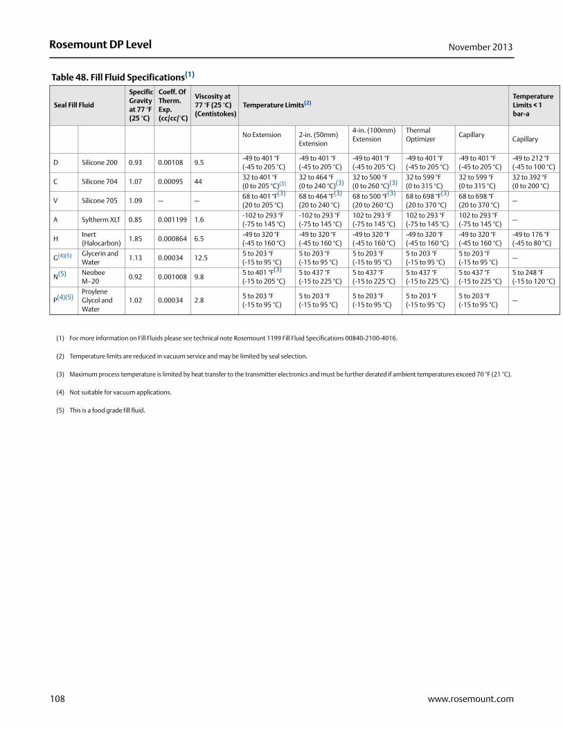
Rosemount DP Level November 2013
perature its < 1 -a
illary
to 212 °F to 100 °C)
o 392 °Fo 200 °C)
to 176 °F to 80 °C)
248 °F to 120 °C)
Table 48. Fill Fluid Specifications(1)
Seal Fill Fluid
Specific Gravity at 77 °F (25 °C)
Coeff. Of Therm. Exp.(cc/cc/°C)
Viscosity at 77 °F (25 °C) (Centistokes)
Temperature Limits(2)TemLimbar
No Extension 2-in. (50mm) Extension
4-in. (100mm) Extension
Thermal Optimizer
CapillaryCap
D Silicone 200 0.93 0.00108 9.5 -49 to 401 °F (-45 to 205 °C)
-49 to 401 °F (-45 to 205 °C)
-49 to 401 °F (-45 to 205 °C)
-49 to 401 °F (-45 to 205 °C)
-49 to 401 °F (-45 to 205 °C)
-49 (-45
C Silicone 704 1.07 0.00095 44 32 to 401 °F (0 to 205 °C)(3)
32 to 464 °F (0 to 240 °C)(3)
32 to 500 °F(0 to 260 °C)(3)
32 to 599 °F(0 to 315 °C)
32 to 599 °F(0 to 315 °C)
32 t(0 t
V Silicone 705 1.09 — —68 to 401 °F(3) (20 to 205 °C)
68 to 464 °F(3) (20 to 240 °C)
68 to 500 °F(3) (20 to 260 °C)
68 to 698 °F(3) (20 to 370 °C)
68 to 698 °F (20 to 370 °C)
—
A Syltherm XLT 0.85 0.001199 1.6 -102 to 293 °F (-75 to 145 °C)
-102 to 293 °F (-75 to 145 °C)
102 to 293 °F(-75 to 145 °C)
102 to 293 °F(-75 to 145 °C)
102 to 293 °F(-75 to 145 °C)
—
HInert (Halocarbon)
1.85 0.000864 6.5 -49 to 320 °F(-45 to 160 °C)
-49 to 320 °F(-45 to 160 °C)
-49 to 320 °F(-45 to 160 °C)
-49 to 320 °F(-45 to 160 °C)
-49 to 320 °F(-45 to 160 °C)
-49 (-45
G(4)(5) Glycerin and Water
1.13 0.00034 12.5 5 to 203 °F(-15 to 95 °C)
5 to 203 °F(-15 to 95 °C)
5 to 203 °F(-15 to 95 °C)
5 to 203 °F(-15 to 95 °C)
5 to 203 °F(-15 to 95 °C)
—
N(5) Neobee M–20
0.92 0.001008 9.8 5 to 401 °F(3)
(-15 to 205 °C)5 to 437 °F(-15 to 225 °C)
5 to 437 °F (-15 to 225 °C)
5 to 437 °F(-15 to 225 °C)
5 to 437 °F(-15 to 225 °C)
5 to(-15
P(4)(5)Proylene Glycol and Water
1.02 0.00034 2.8 5 to 203 °F (-15 to 95 °C)
5 to 203 °F (-15 to 95 °C)
5 to 203 °F (-15 to 95 °C)
5 to 203 °F (-15 to 95 °C)
5 to 203 °F (-15 to 95 °C)
—
(1) For more information on Fill Fluids please see technical note Rosemount 1199 Fill Fluid Specifications 00840-2100-4016.
(2) Temperature limits are reduced in vacuum service and may be limited by seal selection.
(3) Maximum process temperature is limited by heat transfer to the transmitter electronics and must be further derated if ambient temperatures exceed 70 °F (21 °C).
(4) Not suitable for vacuum applications.
(5) This is a food grade fill fluid.
108 www.rosemount.com
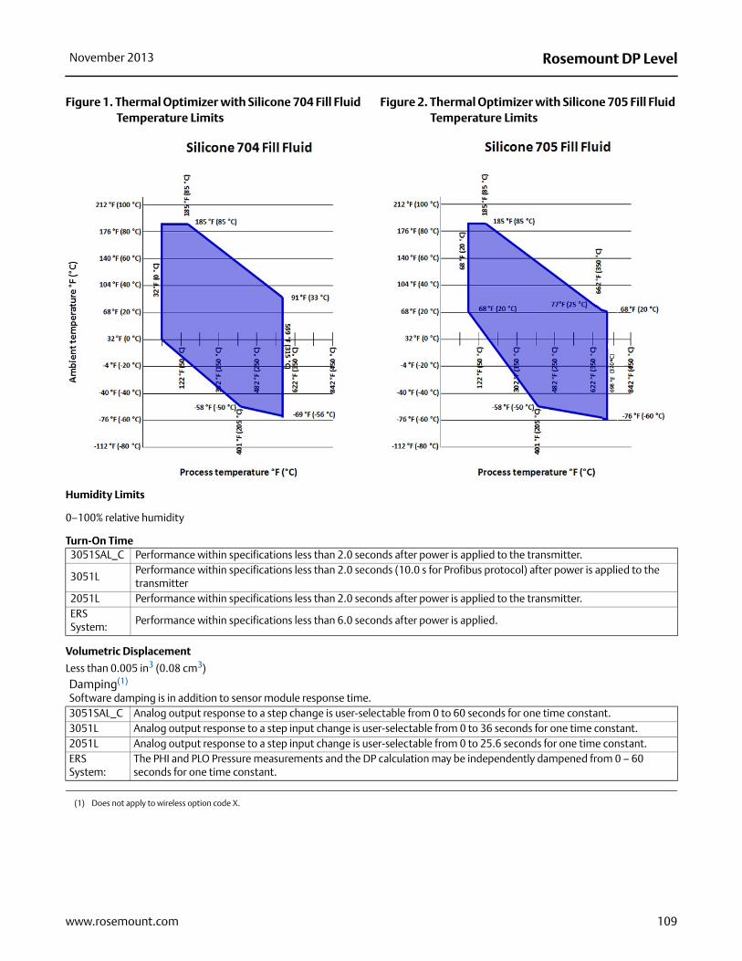
Rosemount DP LevelNovember 2013
Figure 1. Thermal Optimizer with Silicone 704 Fill Fluid Temperature Limits
Figure 2. Thermal Optimizer with Silicone 705 Fill Fluid Temperature Limits
Humidity Limits
0–100% relative humidity
Turn-On Time
Volumetric Displacement
Less than 0.005 in3 (0.08 cm3)
3051SAL_C Performance within specifications less than 2.0 seconds after power is applied to the transmitter.
3051LPerformance within specifications less than 2.0 seconds (10.0 s for Profibus protocol) after power is applied to the transmitter
2051L Performance within specifications less than 2.0 seconds after power is applied to the transmitter.ERS System:
Performance within specifications less than 6.0 seconds after power is applied.
Damping(1)
Software damping is in addition to sensor module response time.3051SAL_C Analog output response to a step change is user-selectable from 0 to 60 seconds for one time constant. 3051L Analog output response to a step input change is user-selectable from 0 to 36 seconds for one time constant.2051L Analog output response to a step input change is user-selectable from 0 to 25.6 seconds for one time constant. ERS System:
The PHI and PLO Pressure measurements and the DP calculation may be independently dampened from 0 – 60 seconds for one time constant.
(1) Does not apply to wireless option code X.
109www.rosemount.com

Rosemount DP Level November 2013
Physical specifications
Electrical connections1/2–14 NPT, PG 13.5, G1/2, and M20 × 1.5 conduit. HART interface connections fixed to terminal block.Non-Wetted PartsCapillary Armor is SST.
3051SAL 3051L 2051L
Electrical Housing
Low-copper aluminum alloy or CF-8M (Cast 316 SST) NEMA 4X, IP 66, IP 68 (66 ft (20 m) for 168 hours)Note: IP 68 not available with Wireless Output.
Low-copper aluminum or CF-3M (Cast version of 316L SST, material per ASTM-A743). NEMA 4X, IP 65, IP 66
Low-copper aluminum or CF-8M (Cast version of 316 SST). Enclosure Type 4X, IP 65, IP 66, IP 68
Coplanar Sensor Module HousingCF-3M (Cast version of 316LSST, material per ASTM-A743)
CF-3M (Cast version of 316L SST, material per ASTM-A743)
CF-3M (Cast version of 316LSST, material per ASTM-A743)
Bolts
Plated carbon steel per ASTM A449, Type 1Austenitic 316 SST per ASTM F593ASTM A453, Class D, Grade 660 SSTASTM A193, Grade B7M alloy steelASTM A193, Class 2, Grade B8M SSTAlloy K-500
ASTM A449, Type 1 (zinc-cobalt plated carbon steel)ASTM F593G, Condition CW1 (Austenitic 316 SST)ASTM A193, Grade B7M (zinc plated alloy steel)Alloy K-500
ASTM A449, Type 1 (zinc-cobalt plated carbon steel)ASTM F593G, Condition CW1 (Austenitic 316 SST)ASTM A193, Grade B7M (zinc plated alloy steel)
Sensor Module Fill Fluid
Silicone or inert halocarbon (Inert is not available with 3051S_CA). In-Line series uses Fluorinert® FC-43.
Silicone 200 or Fluorocarbon oil (Halocarbon or Fluorinert® FC-43 for 3051T)
Silicone 200 or Fluorocarbon oil (Halocarbon or Fluorinert® FC-43 for 2051T)
Process Fill Fluid
Syltherm XLT, Silicone 705, Silicone 704, Silicone 200, inert, glycerin and water, Neobee M-20, propylene glycol and water.
Syltherm XLT, Silicone 705, Silicone 704, Silicone 200, inert, glycerin and water, Neobee M-20, propylene glycol and water
Syltherm XLT, Silicone 705, Silicone 704, Silicone 200, inert, glycerin and water, Neobee M-20, propylene glycol and water
Paint for Aluminum Housing Polyurethane Polyurethane Polyurethane
Cover O-ring Nitrile butadiene (NBR) Nitrile butadiene (NBR) Nitrile butadiene (NBR)
Wireless Antenna
External Antenna (WK1 / WM1): PBT/ PC integrated omnidirectional antennaRemote Antenna (WN1): Fiberglass omnidirectional antenna
N/A N/A
Power Module
Field replaceable, keyed connection eliminates the risk of incorrect installation, Intrinsically Safe Lithium-thionyl chloride Power Module with PBT enclosure
N/A N/A
110 www.rosemount.com
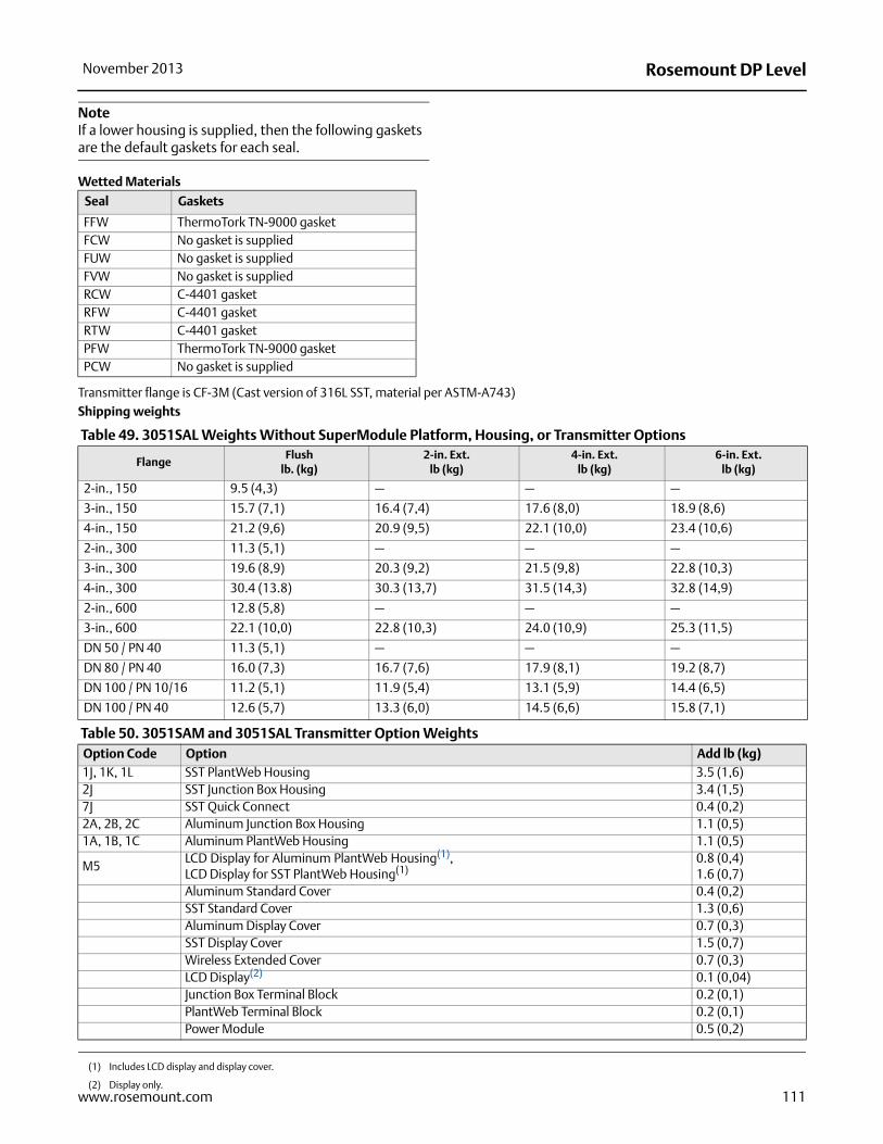
Rosemount DP LevelNovember 2013
111www.rosemount.com
NoteIf a lower housing is supplied, then the following gaskets are the default gaskets for each seal.
Wetted Materials
Transmitter flange is CF-3M (Cast version of 316L SST, material per ASTM-A743)Shipping weights
Table 49. 3051SAL Weights Without SuperModule Platform, Housing, or Transmitter Options
Table 50. 3051SAM and 3051SAL Transmitter Option Weights
Seal Gaskets
FFW ThermoTork TN-9000 gasketFCW No gasket is suppliedFUW No gasket is suppliedFVW No gasket is suppliedRCW C-4401 gasketRFW C-4401 gasketRTW C-4401 gasketPFW ThermoTork TN-9000 gasketPCW No gasket is supplied
FlangeFlush
lb. (kg)2-in. Ext.
lb (kg)4-in. Ext.
lb (kg)6-in. Ext.
lb (kg)
2-in., 150 9.5 (4,3) — — —
3-in., 150 15.7 (7,1) 16.4 (7,4) 17.6 (8,0) 18.9 (8,6)
4-in., 150 21.2 (9,6) 20.9 (9,5) 22.1 (10,0) 23.4 (10,6)
2-in., 300 11.3 (5,1) — — —
3-in., 300 19.6 (8,9) 20.3 (9,2) 21.5 (9,8) 22.8 (10,3)
4-in., 300 30.4 (13.8) 30.3 (13,7) 31.5 (14,3) 32.8 (14,9)
2-in., 600 12.8 (5,8) — — —
3-in., 600 22.1 (10,0) 22.8 (10,3) 24.0 (10,9) 25.3 (11,5)
DN 50 / PN 40 11.3 (5,1) — — —
DN 80 / PN 40 16.0 (7,3) 16.7 (7,6) 17.9 (8,1) 19.2 (8,7)
DN 100 / PN 10/16 11.2 (5,1) 11.9 (5,4) 13.1 (5,9) 14.4 (6,5)
DN 100 / PN 40 12.6 (5,7) 13.3 (6,0) 14.5 (6,6) 15.8 (7,1)
Option Code Option Add lb (kg)1J, 1K, 1L SST PlantWeb Housing 3.5 (1,6)2J SST Junction Box Housing 3.4 (1,5)7J SST Quick Connect 0.4 (0,2)2A, 2B, 2C Aluminum Junction Box Housing 1.1 (0,5)1A, 1B, 1C Aluminum PlantWeb Housing 1.1 (0,5)
M5LCD Display for Aluminum PlantWeb Housing(1), LCD Display for SST PlantWeb Housing(1)
(1) Includes LCD display and display cover.
0.8 (0,4)1.6 (0,7)
Aluminum Standard Cover 0.4 (0,2)SST Standard Cover 1.3 (0,6)Aluminum Display Cover 0.7 (0,3)SST Display Cover 1.5 (0,7)Wireless Extended Cover 0.7 (0,3)LCD Display(2)
(2) Display only.
0.1 (0,04)Junction Box Terminal Block 0.2 (0,1)PlantWeb Terminal Block 0.2 (0,1)Power Module 0.5 (0,2)

Rosemount DP Level November 2013
Table 51. 3051L Weights without Options
FlangeFlush
lb. (kg)2-in. Ext.
lb (kg)4-in. Ext.
lb (kg)6-in. Ext.
lb (kg)
2-in., 15012.5(5,7)
— — —
3-in., 15017.5 (7,9)
19.5 (8,8)
20.5 (9,3)
21.5 (9,7)
4-in., 15023.5
(10,7)26.5
(12,0)28.5
(12,9)30.5
(13,8)2-in., 300 17.5 (7,9) — — —
3-in., 30022.5
(10,2)24.5
(11,1)25.5
(11,6)26.5
(12,0)
4-in., 30032.5
(14,7)35.5
(16,1)37.5
(17,0)39.5
(17,9)
2-in., 60015.3 (6,9)
— — —
3-in., 60025.2
(11,4)27.2
(12,3)28.2
(12,8)29.2
(13,2)
DN 50/PN 4013.8 (6,2)
— — —
DN 80/PN 4019.5 (8,8)
21.5 (9,7)
22.5 (10,2)
23.5 (10,6)
DN 100/PN 10/16
17.8 (8,1)
19.8 (9,0)
20.8 (9,5)
21.8 (9,9)
DN 100/PN 40
23.2 (10,5)
25.2 (11,5)
26.2 (11,9)
27.2 (12,3)
Table 52. 3051L Transmitter Options Weights
Code OptionAddlb (kg)
J, K, L, M Stainless Steel Housing (T) 3.9 (1,8)J, K, L, M Stainless Steel Housing (C, L, H, P) 3.1 (1,4)
M5 LCD display for Aluminum Housing 0.5 (0,2)M6 LCD display for SST Housing 1.25 (0,6)
Table 53. 2051L Weights without Options
FlangeFlush
lb. (kg)2-in. Ext.
lb (kg)4-in. Ext.
lb (kg)6-in. Ext.
lb (kg)
2-in., 15012.5 (5,7)
— — —
3-in., 15017.5 (7,9)
19.5 (8,8)
20.5 (9,3)
21.5 (9,7)
4-in., 15023.5
(10,7)26.5
(12,0)28.5
(12,9)30.5
(13,8)2-in., 300 17.5 (7,9) — — —
3-in., 30022.5
(10,2)24.5
(11,1)25.5
(11,6)26.5
(12,0)
4-in., 30032.5
(14,7)35.5
(16,1)37.5
(17,0)39.5
(17,9)
DN 50/PN 4013.8 (6,2)
— — —
DN 80/PN 4019.5 (8,8)
21.5 (9,7)
22.5 (10,2)
23.5 (10,6)
DN 100/PN 10/16
17.8 (8,1)
19.8 (9,0)
20.8 (9,5)
21.8 (9,9)
DN 100/PN 40
23.2 (10,5)
25.2 (11,5)
26.2 (11,9)
27.2 (12,3)
Table 54. 2051L Transmitter Options Weights
Code OptionAddlb (kg)
J, K, L, M Stainless Steel Housing 3.9 (1,8)M5 LCD display for Aluminum Housing 0.5 (0,2)
112 www.rosemount.com

Rosemount DP LevelNovember 2013
113www.rosemount.com
Seal specifications
Functional specifications
Hygienic Seal ApprovalsHygienic Seals: Tri-Clamp, tank spud, thin wall tank spud, Tri-Clamp inline, and Cherry Burrell “I” line seal conform to 3-A Hygienic Standards for Sensor and Sensor Fittings and Connections used on Milk and Milk Product Equipment, Number 74-03.Hygienic Fill Fluids: The hygienic fill fluids glycerin & water and Propylene Glycol & water meet United States Pharmacopeia (USP) and Food Chemical Codex (FCC) requirements and is Generally Recognized as Safe (GRAS) in accordance with the FDA Code of Federal Regulations Title 21. The hygienic fill fluid Neobee M-20 is approved under 21CFR 172.856 as a direct food additive and under 21 CFR 174.5 as an indirect food additive.Hygienic O-rings: The EPDM, Fluorocarbon (FMK), and Nitrile butadiene (NBR) O-rings for the SSW Tank Spud Seal meet 3-A Hygienic Standard Number 18 Class 1 requirements. The EPDM O-ring also meets USP class VI approval requirements.
Surface Finish Certification (Q16 Option)When ordering the Q16 option in the pressure transmitter model number, the surface finish of the seal diaphragm is certified per BPE 2002 requirements. This surface finish certification is available for Tri-Clamp, Tri-Clamp Inline, Tank Spud, and Thin Wall Tank Spud seal types.
NACE Standard (T Option)NACE (National Association of Corrosion Engineers) standard MR0175/ISO 15156 defines metallic material requirements for resistance to sulfide stress cracking when applied on petroleum production, drilling, gathering and flow line equipment, and field processing facilities to be used in H2S bearing hydrocarbon service. MR0103 provides material requirements exclusive to sour petroleum refining environments. Compliance guidelines are intended to include “wetted” materials as recommended by both NACE standards. The option code T in several of the general purpose seal types limits the wetted material offering. Metallurgical requirements for alloys used are virtually identical for the two standards, but application conditions enforced are different and can limit material acceptance. Contact an Emerson Process Management representative to aid in selecting the proper materials to meet the NACE standard.
Material Traceability (Q8 Option)Material traceability is provided for the seal, upper housing, and if applicable, lower housing/flushing connection or diaphragm extension, upon selecting the option code Q8 in the pressure transmitter model number. Material traceability for the transmitter/seal system is provided per the DIN EN10204 3.1 standard, and is only available for general purpose seal types.
Performance specificationsInstrument Toolkit calculates the remote seal system performance and validates model number configuration.
Remote Seal System Performance Calculation Report (QZ Option)When the QZ option code is specified within the pressure transmitter model structure, Emerson will generate a remote seal system calculation report for the given application. This report quantifies all aspects of remote seal system performance including seal temperature effects, head temperature effects, seal response time, and transmitter total probable error.
Physical specifications
Material of constructionRemote seal materials of construction (diaphragm, upper housing, flange, lower housing/flushing connection, bolts, and gaskets/O-rings) are listed for each remote seal type. Remote seal materials of construction (diaphragm, upper housing, flange, lower housing/flushing connection, bolts, and baskets/O-rings) are listed for each remote seal type.Fill fluids specifications are listed in Table . Transmitter flanged connections and capillary are 316L SST.
Tagging The 1199 remote seal model number is marked on the transmitter nameplate (neck or top label). The pressure transmitter will be tagged in accordance with customer requirements. The standard stainless steel tag is wired to the transmitter. Tag is 0.02-in. (0.051 cm) thick with 0.125-in. (0.318 cm) high letters. A permanently attached tag is available upon request.
Calibration Transmitters are factory calibrated to customer’s specified range. If calibration is not specified, then the transmitters are calibrated at maximum range. Calibration is performed at ambient temperature and pressure.
Custom configurations
Rosemount 3051S, 3051, and 2051 (Option Code C1) If code C1 is ordered, the customer may specify the following data in addition to the standard configuration parameters. Refer to the respective configuration data sheet within the device PDS.Descriptor: 16 alphanumeric characters.Message: 32 alphanumeric characters.Date: Day, month, year.Damping: Sec.

Rosemount DP Level November 2013
Rosemount 3051S Liquid Level certifications
Approved Manufacturing LocationsRosemount Inc. — Chanhassen, Minnesota USA
Emerson Process Management GmbH & Co. — Wessling, Germany
Emerson Process Management Asia Pacific Private Limited — Singapore
Beijing Rosemount Far East Instrument Co., LTD — Beijing, China
Emerson Process Management LTDA — Sorocaba, Brazil
Emerson Process Management (India) Pvt. Ltd. — Mumbai, India
Emerson Process Management, Emerson FZE — Dubai, United Arab
Emirates
Ordinary Location Certification for FMAs standard, the transmitter has been examined and tested to determine that the design meets basic electrical, mechanical, and fire protection requirements by FM, a nationally recognized testing laboratory (NRTL) as accredited by the Federal Occupational Safety and Health Administration (OSHA).
European Directive Information
The EC declaration of conformity for all applicable European directives
for this product can be found at www.rosemount.com. A hard copy may
be obtained by contacting an Emerson Process Management
representative.
ATEX Directive (94/9/EC)Emerson Process Management complies with the
ATEX Directive.
European Pressure Equipment Directive (PED) (97/23/EC)Models 3051S_CA4; 3051S_CD2, 3, 4, 5; (also with P9 option)
Pressure Transmitters — QS Certificate of Assessment -
EC No. 59552-2009-CE-HOU-DNV, Module H Conformity Assessment
All other Model 3051S Pressure Transmitters
— Sound Engineering Practice
Transmitter Attachments: Diaphragm Seal - Process Flange -
Manifold — Sound Engineering Practice
Primary Elements, Flowmeter
— See appropriate Primary Element QIG
Electro Magnetic Compatibility (EMC) (2004/108/EC)EN 61326-1:2006
EN 61326-2-3:2006
HART & FOUNDATION Fieldbus Hazardous Locations Certifications
North American Certifications
FM Approvals
E5 Explosion-proof for Class I, Division 1, Groups B, C, and D, T5 (Ta = 85 °C); Dust Ignition-proof for Class II and Class III, Division 1, Groups E, F, and G, T5 (Ta = 85 °C); hazardous locations; enclosure Type 4X, conduit seal not required when installed according to Rosemount drawing 03151-1003.
I5/IE Intrinsically Safe for use in Class I, Division 1, Groups A, B, C, and D, T4 (Ta = 70 °C for output options A or X; Ta = 60 °C for output option F or W); Class II, Division 1, Groups E, F, and G; Class III, Division 1; Class I, Zone 0 AEx ia IIC T4 (Ta = 70 °C for output options A or X; Ta = 60 °C for output option F or W) when connected in accordance with Rosemount drawing 03151-1006; Non-Incendive for Class I, Division 2, Groups A, B, C, and D; T4 (Ta = 70 °C for output options A or X; Ta = 60 °C for output option F or W) Enclosure Type 4X For entity parameters see control drawing 03151-1006.
Canadian Standards Association (CSA)
All CSA hazardous approved transmitters are certified per ANSI/ISA 12.27.01-2003.
E6 Explosion-proof for Class I, Division 1, Groups B, C, and D; Dust Ignition-proof for Class II and Class III, Division 1, Groups E, F, and G; suitable for Class I, Division 2, Groups A, B, C, and D, when installed per Rosemount drawing 03151-1013, CSA Enclosure Type 4X; conduit seal not required; Dual Seal.
I6/IF Intrinsically Safe for Class I, Division 1, Groups A, B, C, and D when connected in accordance with Rosemount drawings 03151-1016; Dual Seal.For entity parameters see control drawing 03151-1016.
114 www.rosemount.com

Rosemount DP LevelNovember 2013
European Certifications
I1/IA ATEX Intrinsic SafetyCertificate No.: BAS01ATEX1303X II 1GEx ia IIC T4 (Ta = -60 °C to 70 °C) -HART/Remote Display/Quick Connect/HART DiagnosticsEx ia IIC T4 (Ta = -60 °C to 70 °C) -FOUNDATION fieldbusEx ia IIC T4 (Ta = -60 °C to 40 °C) -FISCO
1180
Special conditions for safe use (x)1. The apparatus, excluding the Types 3051 S-T and 3051 S-C
(In-line and Coplanar SuperModule Platforms respectively), is
not capable of withstanding the 500 V test as defined in Clause
6.3.12 of EN 60079-11. This must be considered during
installation.
2. The terminal pins of the Types 3051 S-T and 3051 S-C must be
protected to IP20 minimum.
N1 ATEX Type nCertificate No.: BAS01ATEX3304X II 3 GEx nL IIC T4 (Ta = -40 °C TO 70 °C)Ui = 45 Vdc maxCi = 11.4 nF (Transmitter Output Option A)Ci = 0 (Transmitter Output Option F)Li = 0For remote display, Ci = 0, Li = 60 ì HIP66
Special conditions for safe use (x)The apparatus is not capable of withstanding the 500 V insulation
test required by Clause 6.8.1 of EN 60079-15.
This must be taken into account when installing the apparatus.
NoteRTD Assembly is not included with the 3051SFx Type n Approval.
ND ATEX Dust Certificate No.: BAS01ATEX1374X II 1 DEx tD A20 IP66 T105°C (-20 °C Tamb 85 °C)Vmax = 42.4 volts maxIP66
1180
Special conditions for safe use (x)1. Cable entries must be used which maintain the ingress
protection of the enclosure to at least IP66.2. Unused cable entries must be filled with suitable blanking plugs
which maintain the ingress protection of the enclosure to at least IP66.
3. Cable entries and blanking plugs must be suitable for the ambient range of the apparatus and capable of withstanding a 7J impact test.
4. The 3051S SuperModule must be securely screwed in place to maintain the ingress protection of the enclosure. (The 3051S SuperModule must be properly assembled to the 3051S housing to maintain ingress protection.)
E1 ATEX Flameproof Certificate No.: KEMA00ATEX2143X II 1/2 GEx d IIC T6 (-50 °C Tamb 65 °C)Ex d IIC T5 (-50 °C Tamb 80 °C)Vmax = 42.4 V
1180
Special conditions for safe use (x)
1. The Ex d blanking elements, cable glands, and wiring shall be suitable for a temperature of 90 °C.
2. The 3051S SuperModule contains a thin wall diaphragm. Installation, maintenance and use shall take into account the environmental conditions to which the diaphragm will be subjected. The manufacturer's instructions for maintenance shall be followed in detail to assure safety during its expected lifetime.
3. In case of repair, contact the manufacturer for information on the dimensions of the flameproof joints.
Japanese Certifications
E4 TIIS FlameproofEx d IIC T6
Input Parameters
Loop / Power
Groups
Ui = 30 VHART / FOUNDATION fieldbus/ Remote Display / Quick Connect / HART Diagnostics
Ui = 17.5 V FISCO
Ii = 300 mAHART / FOUNDATION fieldbus/ Remote Display / Quick Connect / HART Diagnostics
Ii = 380 mA FISCO
Pi = 1.0 WHART / Remote Display / Quick Connect / HART Diagnostics
Pi = 1.3 W FOUNDATION fieldbusPi = 5.32 W FISCOCi = 30 nF SuperModule PlatformCi = 11.4 nF HART / HART Diagnostics / Quick Connect
Ci = 0FOUNDATION fieldbus / Remote Display / FISCO
Li = 0HART / FOUNDATION fieldbus/ FISCO / Quick Connect / HART Diagnostics
Li = 60 μH Remote Display
RTD Assembly (3051SFx Option T or R)
Ui = 5 VdcIi = 500 mAPi = 0.63 W
115www.rosemount.com

Rosemount DP Level November 2013
116 www.rosemount.com
China Certifications
E3 China Flameproof, Dust Ignition-proofNEPSI Certificate No. (manufactured in Chanhassen, MN): GYJ091035Certificate No. (manufactured in Beijing, China and Singapore): GYJ111400XCertificate No. (3051SFx RTC, BMMC, SMMC): GYJ071086Ex d IIC T5/T6DIP A20 Ta 105C IP66
NoteRefer to Appendix B of the 3051S Reference Manual (document number 00809-0100-4801) for Special Conditions for Safe Use.
I3 China Intrinsic Safety, Dust Ignition-proofNEPSI Certificate No. (manufactured in Chanhassen, MN): GYJ081078 Certificate No. (manufactured in Beijing, China and Singapore): GYJ111401XCertificate No. (3051SFx RTC, BMMC, SMMC): GYJ071293Ex ia IIC T4DIP A21 TA T4 IP66
NoteRefer to Appendix B of the 3051S Reference Manual (document number 00809-0100-4801) for Special Conditions for Safe Use.
Certificate Description
TC15682 Coplanar with Junction Box HousingTC15683 Coplanar with PlantWeb Housing
TC15684Coplanar with PlantWeb Housing and LCD Display
TC15685 In-Line SST with Junction Box Housing
TC15686In-Line Alloy C-276 with Junction Box Housing
TC15687 In-Line SST with PlantWeb HousingTC15688 In-Line Alloy C-276 with PlantWeb Housing
TC15689In-Line SST with PlantWeb Housing and LCD Display
TC15690In-Line Alloy C-276 with PlantWeb Housing and LCD Display
TC17102 Remote Display
TC170993051SFA/C/P SST/Alloy C-276 with PlantWeb Housing and LCD Display
TC171003051SFA/C/P SST/Alloy C-276 with Junction Box Housing
TC171013051SFA/C/P SST/Alloy C-276 with PlantWeb Housing and Remote Display
Table 55. Input Parameters
Loop / Power
Groups
Ui = 30 VHART / FOUNDATION fieldbus / Remote Display / Quick Connect / HART Diagnostics
Ii = 300 mAHART / FOUNDATION fieldbus / Remote Display / Quick Connect / HART Diagnostics
Pi = 1.0 WHART / Remote Display / Quick Connect / HART Diagnostics
Pi = 1.3 W FOUNDATION fieldbusCi = 38 nF SuperModule PlatformCi = 11.4 nF HART / HART Diagnostics / Quick ConnectCi = 0 FOUNDATION fieldbus / Remote DisplayLi = 0 SuperModule Platform / FOUNDATION fieldbusLi = 2.4 μH HART / Quick Connect / HART DiagnosticsLi = 58.2 μH Remote Display
RTD Assembly (3051SFx Option T or R)
Ui = 5 VdcIi = 500 mAPi = 0.63 W
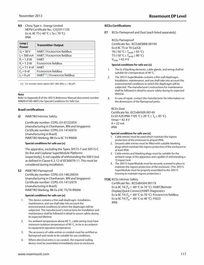
Rosemount DP LevelNovember 2013
N3 China Type n - Energy LimitedNEPSI Certificate No.: GYJ101112XEx nL IIC T5 (-40 °C Ta 70 °C)IP66
NoteRefer to Appendix B of the 3051S Reference Manual (document number 00809-0100-4801) for Special Conditions for Safe Use.
Brazil certifications
I2 INMETRO Intrinsic Safety
Certificate number: CEPEL-EX-0722/05X (manufacturing in Chanhassen, MN and Singapore)Certificate number: CEPEL-EX-1414/07X (manufacturing in Brazil)INMETRO Marking: BR-Ex ia IIC T4 IP66W
Special conditions for safe use (x)
The apparatus, excluding the Types 3051S-T and 3051S-C (In-line and Coplanar SuperModule Platforms respectively), is not capable of withstanding the 500 V test as defined in Clause 6.3.12 of IEC60079-11. This must be considered during installation.
E2 INMETRO FlameproofCertificate number: CEPEL-EX-140/2003X (manufacturing in Chanhassen, MN and Singapore)Certificate number: CEPEL-EX-1413/07X (manufacturing in Brazil)INMETRO Marking: BR-Ex d IIC T5/T6 IP66W
Special conditions for safe use (x)
1. This device contains a thin wall diaphragm. Installation, maintenance, and use shall take into account the environmental conditions to which the diaphragm will be subjected. The manufacturer’s instructions for installation and maintenance shall be followed in detail to assure safety during its expected lifetime.
2. For ambient temperature above 60 °C, cable wiring must have minimum isolation temperature of 90 °C, to be in accordance to equipment operation temperature.
3. The accessory of cable entries or conduit must be certified as flameproof and needs to be suitable for use conditions.
4. Where electrical entry is via conduit, the required sealing device must be assembled immediately close to enclosure.
IECEx Certifications
E7 IECEx Flameproof and Dust (each listed separately)
IECEx FlameproofCertificate No.: IECExKEM08.0010XEx d IIC T5 or T6 Ga/GbT6 (-50 °C Tamb 65 °C)T5 (-50 °C Tamb 80 °C)Vmax = 42.4 V
Special conditions for safe use (x)
1. The Ex d blanking elements, cable glands, and wiring shall be suitable for a temperature of 90 °C.
2. The 3051S SuperModule contains a thin wall diaphragm. Installation, maintenance, and use shall take into account the environmental conditions to which the diaphragm will be subjected. The manufacturer's instructions for maintenance shall be followed in detail to assure safety during its expected lifetime.
3. In case of repair, contact the manufacturer for information on the dimensions of the flameproof joints.
IECEx DustCertificate No. IECExBAS09.0014XEx tD A20 IP66 T105 °C (-20 °C Ta 85 °C)Vmax = 42.4 VA = 22 mAIP66
Special conditions for safe use (x)1. Cable entries must be used which maintain the ingress
protection of the enclosure to at least IP66.2. Unused cable entries must be filled with suitable blanking
plugs which maintain the ingress protection of the enclosure to at least IP66.
3. Cable entries and blanking plugs must be suitable for the ambient range of the apparatus and capable of withstanding a 7J impact test.
4. The 3051S SuperModule must be securely screwed in place to maintain the ingress protection of the enclosure. (The 3051S SuperModule must be properly assembled to the 3051S housing to maintain ingress protection.)
I7/IG IECEx Intrinsic SafetyCertificate No.: IECExBAS04.0017XEx ia IIC T4 (Ta = -60 °C to 70 °C) -HART/Remote Display/Quick Connect/HART Diagnostics Ex ia IIC T4 (Ta = -60 °C to 70 °C) -FOUNDATION fieldbusEx ia IIC T4 (Ta = -60 °C to 40 °C) -FISCOIP66
Loop / Power
Transmitter Output
Ui = 30 V HART / FOUNDATION fieldbusIi = 300 mA HART / FOUNDATION fieldbusPi = 1.0 W HARTPi = 1.3 W FOUNDATION fieldbusCi = 11.4 nF HARTCi = 0 nF FOUNDATION fieldbusLi = 0 μH HART(1) / FOUNDATION fieldbus
(1) For remote meter option (M7, M8, M9), Li = 60 μH.
117www.rosemount.com

Rosemount DP Level November 2013
Special conditions for safe use (x)
1.The 3051S HART 4-20 mA, 3051S FOUNDATION fieldbus, and 3051S FISCO are not capable of withstanding the 500 V test as defined in clause 6.3.12 of IEC 60079-11. This must be taken into account during installation.
2.The terminal pins of the Types 3051S-T and 3051S-C must be protected to IP20 minimum.
N7 IECEx Type nCertificate No.: IECExBAS04.0018XEx nC IIC T4 (-40 °C Ta +70 °C)Ui = 45 Vdc MaxIP66Special conditions for safe use (x)The apparatus is not capable of withstanding the 500 V insulation test required by Clause 8 of IEC 60079-15:1987.
Combinations of certifications
Stainless steel certification tag is provided when optional approval is specified. Once a device labeled with multiple approval types is installed, it should not be reinstalled using any other approval types. Permanently mark the approval label to distinguish it from unused approval types.
K1 Combination of E1, I1, N1, and ND
K2 Combination of E2 and I2
K5 Combination of E5 and I5
K6 Combination of E6 and I6
K7 Combination of E7, I7, and N7
KA Combination of E1, I1, E6, and I6
KB Combination of E5, I5, I6, and E6
KC Combination of E5, E1, I5, and I1
KD Combination of E5, I5, E6, I6, E1, and I1
Table 56. Input Parameters
Loop / Power Groups
Ui = 30 VHART / FOUNDATION fieldbus/ Remote Display / Quick Connect / HART Diagnostics
Ui = 17.5 V FISCO
Ii = 300 mAHART / FOUNDATION fieldbus/ Remote Display / Quick Connect / HART Diagnostics
Ii = 380 mA FISCO
Pi = 1.0 WHART / Remote Display / Quick Connect / HART Diagnostics
Pi = 1.3 W FOUNDATION fieldbusPi = 5.32 W FISCOCi = 30 nF SuperModule Platform
Ci = 11.4 nFHART / HART Diagnostics / Quick Connect
Ci = 0FOUNDATION fieldbus / Remote Display / FISCO
Li = 0HART / FOUNDATION fieldbus/ FISCO / Quick Connect / HART Diagnostics
Li = 60 H Remote Display
RTD Assembly (3051SFx Option T or R)
Ui = 5 VdcIi = 500 mAPi = 0.63 W
118 www.rosemount.com

Rosemount DP LevelNovember 2013
3051S ERS System CertificationsApproved Manufacturing Locations
Rosemount Inc. – Chanhassen, Minnesota, USA
Emerson Process Management GmbH & Co. – Wessling, Germany
Emerson Process Management Asia Pacific Private Limited – Singapore
Beijing Rosemount Far East Instrument Co., LTD – Beijing, China
Ordinary Location Certification for FM ApprovalsAs standard, the transmitter has been examined and tested to determine that the design meets basic electrical, mechanical, and fire protection requirements by FM, a nationally recognized testing laboratory (NRTL) as accredited by the Federal Occupational Safety and Health Administration (OSHA).
European Directive InformationThe EC declaration of conformity for all applicable European directives for this product can be found at www.rosemount.com. A hard copy may be obtained by contacting an Emerson Process Management representative.
ATEX Directive (94/9/EC)Emerson Process Management complies with the
ATEX Directive.
European Pressure Equipment Directive (PED) (97/23/EC)Models 3051S_CA4; 3051S_CD2, 3, 4, 5; (also with P9 option)
Pressure Transmitters — QS Certificate of Assessment -
EC No. 59552-2009-CE-HOU-DNV, Module H Conformity Assessment
All other Model 3051S Pressure Transmitters
— Sound Engineering Practice
Transmitter Attachments: Diaphragm Seal - Process Flange -
Manifold — Sound Engineering Practice
Primary Elements, Flowmeter
— See appropriate Primary Element QIG
Electro Magnetic Compatibility (EMC) (2004/108/EC)EN 61326-1:2006
EN 61326-2-3:2006
Hazardous Locations Certifications
North American Certifications
FM Approvals
E5 Explosion-proof for Class I, Division 1, Groups B, C, and D; Dust Ignition-proof for Class II and Class III, Division 1, Groups E, F, and G; hazardous locations; enclosure Type 4X, conduit seal not required.
I5 Intrinsically Safe for use in Class I, Division 1, Groups A, B, C, and D; Class II, Division 1, Groups E, F, and G; Class III, Division 1; Class I, Zone 0 AEx ia IIC when connected in accordance with Rosemount drawing 03151-1306; Non-Incendive for Class I, Division 2, Groups A, B, C, and D Enclosure Type 4X
For entity parameters see control drawing 03151-1306.
Canadian Standards Association (CSA) All CSA hazardous approved transmitters are certified per ANSI/ISA
12.27.01-2003.
E6 Explosion-proof for Class I, Division 1, Groups B, C, and D; Dust Ignition-Proof for Class II and Class III, Division 1, Groups E, F, and G; suitable for Class I, Division 2, Groups A, B, C, and D, CSA Enclosure Type 4X; conduit seal not required; Dual Seal.
I6 Intrinsically Safe for Class I, Division 1, Groups A, B, C, and D when connected in accordance with Rosemount Drawings 03151-1316; Dual Seal.
For entity parameters see control drawing 03151-1316.
European Certifications
I1 ATEX Intrinsic SafetyCertificate No.: BAS01ATEX1303X II 1GEx ia IIC T4 (Ta = -60 °C to 70 °C)
1180
Special Conditions for Safe Use (X)
The apparatus is not capable of withstanding the 500 V test as defined in Clause 6.3.12 of EN 60079-11. This must be considered during installation.
N1 ATEX Type nCertificate No.: BAS01ATEX3304X II 3 GEx nL IIC T4 (Ta = -40 °C TO 70 °C)Ui = 45 Vdc maxIP66
Special conditions for safe use (x)The apparatus is not capable of withstanding the 500 V insulation
test required by Clause 6.8.1 of EN 60079-15.
This must be taken into account when installing the apparatus.
Table 57. Input Parameters
Loop / Power
Ui = 30 VIi = 300 mAPi = 1 WCi = 12 nFLi = 33 H
119www.rosemount.com
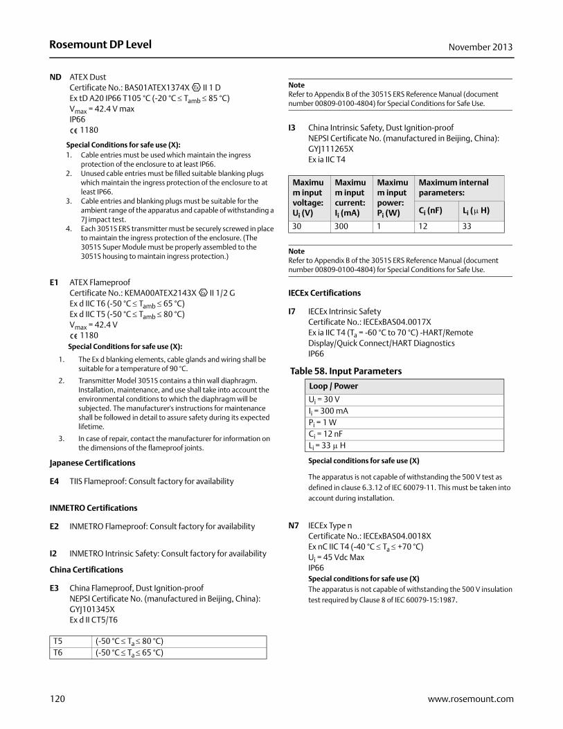
Rosemount DP Level November 2013
ND ATEX Dust Certificate No.: BAS01ATEX1374X II 1 DEx tD A20 IP66 T105 °C (-20 °C Tamb 85 °C)Vmax = 42.4 V maxIP66
1180
Special Conditions for safe use (X):1. Cable entries must be used which maintain the ingress
protection of the enclosure to at least IP66. 2. Unused cable entries must be filled suitable blanking plugs
which maintain the ingress protection of the enclosure to at least IP66.
3. Cable entries and blanking plugs must be suitable for the ambient range of the apparatus and capable of withstanding a 7J impact test.
4. Each 3051S ERS transmitter must be securely screwed in place to maintain the ingress protection of the enclosure. (The 3051S Super Module must be properly assembled to the 3051S housing to maintain ingress protection.)
E1 ATEX Flameproof Certificate No.: KEMA00ATEX2143X II 1/2 GEx d IIC T6 (-50 °C Tamb 65 °C)Ex d IIC T5 (-50 °C Tamb 80 °C)Vmax = 42.4 V
1180Special Conditions for safe use (X):
1. The Ex d blanking elements, cable glands and wiring shall be suitable for a temperature of 90 °C.
2. Transmitter Model 3051S contains a thin wall diaphragm. Installation, maintenance, and use shall take into account the environmental conditions to which the diaphragm will be subjected. The manufacturer's instructions for maintenance shall be followed in detail to assure safety during its expected lifetime.
3. In case of repair, contact the manufacturer for information on the dimensions of the flameproof joints.
Japanese Certifications
E4 TIIS Flameproof: Consult factory for availability
INMETRO Certifications
E2 INMETRO Flameproof: Consult factory for availability
I2 INMETRO Intrinsic Safety: Consult factory for availability
China Certifications
E3 China Flameproof, Dust Ignition-proofNEPSI Certificate No. (manufactured in Beijing, China): GYJ101345XEx d II CT5/T6
NoteRefer to Appendix B of the 3051S ERS Reference Manual (document number 00809-0100-4804) for Special Conditions for Safe Use.
I3 China Intrinsic Safety, Dust Ignition-proofNEPSI Certificate No. (manufactured in Beijing, China): GYJ111265XEx ia IIC T4
NoteRefer to Appendix B of the 3051S ERS Reference Manual (document number 00809-0100-4804) for Special Conditions for Safe Use.
IECEx Certifications
I7 IECEx Intrinsic SafetyCertificate No.: IECExBAS04.0017XEx ia IIC T4 (Ta = -60 °C to 70 °C) -HART/Remote Display/Quick Connect/HART Diagnostics IP66
Special conditions for safe use (X)
The apparatus is not capable of withstanding the 500 V test as defined in clause 6.3.12 of IEC 60079-11. This must be taken into account during installation.
N7 IECEx Type nCertificate No.: IECExBAS04.0018XEx nC IIC T4 (-40 °C Ta +70 °C)Ui = 45 Vdc MaxIP66Special conditions for safe use (X)The apparatus is not capable of withstanding the 500 V insulation test required by Clause 8 of IEC 60079-15:1987.
T5 (-50 °C Ta 80 °C)T6 (-50 °C Ta 65 °C)
Maximum input voltage: Ui (V)
Maximum input current:Ii (mA)
Maximum input power:Pi (W)
Maximum internal parameters:
Ci (nF) Li ( H)
30 300 1 12 33
Table 58. Input Parameters
Loop / Power
Ui = 30 VIi = 300 mAPi = 1 WCi = 12 nFLi = 33 H
120 www.rosemount.com

Rosemount DP LevelNovember 2013
E7 IECEx Flameproof and Dust (each listed separately)
IECEx FlameproofCertificate No.: IECExKEM08.0010X Ex d IIC T6 (-50 °C Tamb 65 °C)Ex d IIC T5 (-50 °C Tamb 80 °C)Vmax = 42.4 V
Special conditions for safe use (X)
1. The Ex d blanking elements, cable glands and wiring shall be suitable for a temperature of 90 °C.
2. Transmitter Model 3051S contains a thin wall diaphragm. Installation, maintenance, and use shall take into account the environmental conditions to which the diaphragm will be subjected. The manufacturer's instructions for maintenance shall be followed in detail to assure safety during its expected lifetime.
3. In case of repair, contact the manufacturer for information on the dimensions of the flameproof joints.
IECEx DustCertificate No. IECExBAS09.0014XEx tD A20 IP66 T105 °C (-20 °C Tamb 85 °C)Vmax = 42.4 VA = 22 mAIP66
Special conditions for safe use (X)1. Cable entries must be used which maintain the ingress
protection of the enclosure to at least IP66.2. Unused cable entries must be filled with suitable blanking
plugs which maintain the ingress protection of the enclosure to at least IP66.
3. Cable entries and blanking plugs must be suitable for the ambient range of the apparatus and capable of withstanding a 7J impact test.
4. Each 3051S ERS sensor must be securely screwed in place to maintain the ingress protection of the enclosure. (Each sensor module must be properly assembled to the housing to maintain ingress protection.)
Combinations of certificationsStainless steel certification tag is provided when optional approval is
specified. Once a device labeled with multiple approval types is
installed, it should not be reinstalled using any other approval types.
Permanently mark the approval label to distinguish it from unused
approval types.
K1 Combination of E1, I1, N1, and ND
K2 Combination of E2 and I2
K5 Combination of E5 and I5
K6 Combination of E6 and I6
K7 Combination of E7, I7, and N7
KA Combination of E1, E6, I1, and I6
KB Combination of E5, E6, I1, and I6
KC Combination of E5, E1, I5, and I1
KD Combination of E5, E6, E1, I5, I6, and I1
121www.rosemount.com

Rosemount DP Level November 2013
3051L Product CertificationsApproved Manufacturing LocationsRosemount Inc. — Chanhassen, Minnesota USAEmerson Process Management GmbH & Co. — Wessling, GermanyEmerson Process Management Asia Pacific Private Limited — SingaporeBeijing Rosemount Far East Instrument Co., LTD — Beijing, China
European Directive InformationThe EC declaration of conformity for all applicable European directives for this product can be found on the Rosemount website at www.rosemount.com. A hard copy may be obtained by contacting an Emerson Process Management representative.
ATEX Directive (94/9/EC)All 3051 transmitters comply with the ATEX Directive.
European Pressure Equipment Directive (PED) (97/23/EC)3051CA4; 3051CG2, 3, 4, 5; 3051CD2, 3, 4, 5 (also with P9 option); 3051HD2, 3, 4, 5; 3051HG2, 3, 4, 5; 3051PD2, 3; and 3051PG2, 3, 4, 5 Pressure Transmitters — QS Certificate of Assessment -
EC No. 59552-2009-CE-HOU-DNVModule H Conformity Assessment
All other 3051/3001 Pressure Transmitters— Sound Engineering Practice
Transmitter Attachments: Diaphragm Seal - Process Flange - Manifold
— Sound Engineering Practice
Electro Magnetic Compatibility (EMC) (2004/108/EC)All 3051 Pressure Transmitters meet all of the requirements of EN61326-1:2006 EN61326-2-3: 2006 and NAMUR NE-21
Ordinary Location Certification for Factory MutualAs standard, the transmitter has been examined and tested to determine that the design meets basic electrical, mechanical, and fire protection requirements by FM, a nationally recognized testing laboratory (NRTL) as accredited by the Federal Occupational Safety and Health Administration (OSHA).
3051L HART Protocol
Hazardous Locations Certifications
North American Certifications
FM Approvals
E5 Explosion-Proof for Class I, Division 1, Groups B, C, and D. Dust-Ignition-Proof for Class II, Division 1, Groups E, F, and G. Dust-Ignition-Proof for Class III, Division 1. Factory Sealed, Enclosure Type 4X
I5 Intrinsically Safe for use in Class I, Division 1, Groups A, B, C, and D; Class II, Division 1, Groups E, F, and G; Class III, Division 1 when connected per Rosemount drawing 03031-1019; Non-incendive for Class I, Division 2, Groups A, B, C, and D.Temperature Code:T4 (Ta = 40 °C), T3 (Ta = 85 °C), Enclosure Type 4XFor input parameters see control drawing 03031-1019.
Canadian Standards Association (CSA)
All CSA hazardous approved transmitters are certified per ANSI/ISA 12.27.01-2003.
E6 Explosion-Proof for Class I, Division 1, Groups B, C, and D. Dust-Ignition-Proof for Class II and Class III, Division 1, Groups E, F, and G. Suitable for Class I, Division 2 Groups A, B, C, and D for indoor and outdoor hazardous locations. Enclosure type 4X, factory sealed
C6 Explosion-Proof and intrinsically safe approval. Intrinsically safe for Class I, Division 1, Groups A, B, C, and D when connected in accordance with Rosemount drawings 03031-1024. Temperature Code T3C.Explosion-Proof for Class I, Division 1, Groups B, C, and D. Dust-Ignition-Proof for Class II and Class III, Division 1, Groups E, F, and G. Suitable for Class I, Division 2 Groups A, B, C, and D hazardous locations. Enclosure type 4X, factory sealedFor input parameters see control drawing 03031-1024.
European Certifications
I1 ATEX Intrinsic Safety and Dust Certification No.: BAS 97ATEX1089X II 1 GD Ex ia IIC T4 (–60 Ta +70 °C)Dust Rating: Ex tD A20 T80 °C (–20 Ta 40 °C) IP66
1180
Table 59. Input ParametersUi = 30 VIi = 200 mAPi = 0.9 W Ci = 0.012 μF
122 www.rosemount.com

Rosemount DP LevelNovember 2013
Special Conditions for Safe Use (X): When the optional transient protection terminal block is installed, the apparatus is not capable of withstanding the 500 V insulation test required by Clause 6.3.12 of EN60079-11. This must be taken into account when installing the apparatus.The enclosure may be made of aluminium alloy and given a protective polyurethane paint finish; however, care should be taken to protect it from impact or abrasion if located in Zone 0.
N1 ATEX Type n and Dust Certification No.: BAS 00ATEX3105X II 3 GD Ui = 55 Vdc maxEx nA nL T5 (–40 °C Tamb 70 °C)Dust rating: Ex tD A22 T80 °C (–20 Ta 40 °C) IP66
Special Conditions for Safe Use (X): When the optional transient protection terminal block is installed, the apparatus is not capable of withstanding a 500 V r.m.s. test to case. This must be taken into account on any installation in which it is used, for example, by assuring that the supply to the apparatus is galvanically isolated.
E8 ATEX Flame-Proof and Dust Certification No.: KEMA 00ATEX2013X II 1/2 GD Ex d IIC T6 (–50 Ta 65 °C)
T5 (–50 Ta 80 °C)Dust rating: Ex tD A20/A21 T90 °C, IP66
1180Vmax = 55 Vdc
Special Conditions for Safe Use (X): This device contains a thin wall diaphragm. Installation, maintenance, and use shall take into account the environmental conditions to which the diaphragm will be subjected. The manufacturer’s instructions for installation and maintenance shall be followed in detail to assure safety during its expected lifetime.In case of repair, contact Rosemount for dimensions of the flameproof joints.
Japanese Certifications
E4 TIIS Flame-ProofEx d IIC T6
IECEx Certifications
I7 IECEx Intrinsic Safety Certification No.: IECEx BAS 09.0076XEx ia IIC T4 (–60 °C Ta 70 °C)IP66
Special Conditions for Safe Use (X): When the optional transient protection terminal block is installed, the apparatus is not capable of withstanding the 500 V insulation test required by Clause 6.3.12 of IEC 60079-11. This must be taken into account when installing the apparatus.The enclosure may be made of aluminium alloy and given a protective polyurethane paint finish; however care should be taken to protect it from impact or abrasion located in Zone 0.
E7 IECEx Explosion-Proof (Flame-Proof) Certification No.: IECEx KEM 09.0034XGa/Gb Ex d IIC T6 or T5 Ex tD A20/A21 IP66 T90 °CIP66
Special Conditions for Safe Use (X): This device contains a thin wall diaphragm. Installation, maintenance, and use shall take into account the environmental conditions to which the diaphragm will be subjected. The manufacturer's instructions for installation and maintenance shall be followed in detail to assure safety during its expected lifetime.
For information on the dimensions of the flameproof joints the manufacturer shall be contacted.
N7 IECEx Type n Certification No.: IECEx BAS 09.0077XEx nA nL IIC T5 (–40 °C Ta 70 °C)IP66
Table 60. RTD Assembly (3051CFx Option T or R)Ui = 5 VdcIi = 500 mAPi = 0.63 W
Certificate Description
C158503051C/D/1 4–20 mA HART — no display
C158513051C/D/1 4–20 mA HART — with display
Table 61. Input ParametersUi = 30 VIi = 200 mAPi = 0.9 W Ci = 0.012 μF
Table 62. RTD Assembly (3051CFx Option T or R)Ui = 5 VdcIi = 500 mAPi = 0.63 W
123www.rosemount.com

Rosemount DP Level November 2013
Special Conditions for Safe Use (X):
The apparatus is not capable of withstanding the 500 V insulation test required by clause 6.8.1 of IEC 60079-15. This must be taken into account when installing the apparatus.
Combinations of Certifications
Stainless steel certification tag is provided when optional approval is
specified. Once a device labeled with multiple approval types is
installed, it should not be reinstalled using any other approval types.
Permanently mark the approval label to distinguish it from unused
approval types.
K5 E5 and I5 combination
KB K5 and C6 combination
KD K5, C6, I1, and E8 combination
K6 C6, I1, and E8 combination
K8 E8 and I1 combination
K7 E7, I7, and N7 combination
3051L Fieldbus Protocol
Hazardous Locations Certifications
North American Certifications
FM Approvals
E5 Explosion-Proof for Class I, Division 1, Groups B, C, and D. Dust-Ignition-Proof for Class II, Division 1, Groups E, F, and G. Dust-Ignition-Proof for Class III, Division 1. Factory sealed. Enclosure Type 4X.
I5 Intrinsically Safe for use in Class I, Division 1, Groups A, B, C, and D; Class II, Division 1, Groups E, F, and G; Class III, Division 1 when connected per Rosemount drawing 03031-1019; Non-incendive for Class I, Division 2, Groups A, B, C, and D.
Temperature Code: T4 (Ta = 60 °C), Enclosure Type 4XFor input parameters see control drawing 03031-1019.
Canadian Standards Association (CSA)
All CSA hazardous approved transmitters are certified per ANSI/ISA 12.27.01-2003.
E6 Explosion-Proof for Class I, Division 1, Groups B, C, and D. Dust-Ignition-Proof for Class II and Class III, Division 1, Groups E, F, and G. Suitable for Class I, Division 2 Groups A, B, C, and D for indoor and outdoor hazardous locations. Enclosure type 4X, factory sealed
C6 Explosion-Proof and intrinsically safe approval. Intrinsically safe for Class I, Division 1, Groups A, B, C, and D when connected in accordance with Rosemount drawings 03031-1024. Temperature Code T3C.Explosion-Proof for Class I, Division 1, Groups B, C, and D. Dust-Ignition-Proof for Class II and Class III, Division 1, Groups E, F, and G. Suitable for Class I, Division 2 Groups A, B, C, and D hazardous locations. Enclosure type 4X, factory sealedFor input parameters see control drawing 03031-1024.
European Certifications
I1 ATEX Intrinsic Safety and Dust Certification No.: BAS 98ATEX1355X II 1 GD Ex ia IIC T4 (Tamb = –60 to +60 °C)Dust Rating: Ex tD A20 T70 °C (Tamb –20 to 40 °C) IP66
1180
Special Conditions for Safe Use (X):
The device is not capable of withstanding the 500 V insulation test required by Clause 6.3.12 of EN60079-11. This must be taken into account when installing the apparatus.The enclosure may be made of aluminium alloy and given a protective polyurethane paint finish; however, care should be taken to protect it from impact or abrasion if located in Zone 0.
IA ATEX FISCO Intrinsic Safety Certification No.: BAS 98ATEX1355X II 1 G Ex ia IIC T4 (Tamb = –60 to +60 °C)IP66
1180
Table 63. Input ParametersUi = 30 VIi = 300 mAPi = 1.3 W Ci = 0 μF
Table 64. RTD Assembly (3051CFx Option T or R)Ui = 5 VdcIi = 500 mAPi = 0.63 W
Table 65. Input ParametersUi = 17.5 VIi = 380 mAPi = 5.32 W Ci = 5 μFLi = 10 μH
124 www.rosemount.com

Rosemount DP LevelNovember 2013
Special Conditions for Safe Use (X): The device is not capable of withstanding the 500 V insulation test required by Clause 6.3.12 of EN60079-11. This must be taken into account when installing the apparatus.The enclosure may be made of aluminium alloy and given a protective polyurethane paint finish; however, care should be taken to protect it from impact or abrasion if located in Zone 0.
N1 ATEX Type n and Dust Certification No.: BAS 98ATEX3356X II 3 GD Ui = 40 Vdc maxEx nL IIC T5 (Ta = –40 °C to 70 °C)Dust rating: Ex tD A22 T80 °C (Tamb = –20 to 40 °C) IP66
Special Conditions for Safe Use (X): The device is not capable of withstanding the 500 V insulation test required by Clause 6.8.1 of EN60079-15. This must be taken into account when installing the apparatus.
E8 ATEX Flame-Proof and Dust Certification No.: KEMA 00ATEX2013X II 1/2 GD Ex d IIC T6 (Tamb = –50 to 65 °C)
T5 (Tamb = –50 to 80 °C)Dust rating: Ex tD A20/21 T90 °C, IP66
1180Vmax = 55 Vdc
Special Conditions for Safe Use (X): This device contains a thin wall diaphragm. Installation, maintenance, and use shall take into account the environmental conditions to which the diaphragm will be subjected. The manufacturer’s instructions for installation and maintenance shall be followed in detail to assure safety during its expected lifetime.In case of repair, contact Rosemount for dimensions of the flameproof joints.
Japanese Certifications
E4 TIIS Flame-ProofEx d IIC T6
IECEx Certifications
I7 IECEx Intrinsic Safety Certification No.: IECEx BAS 09.0076XEx ia IIC T4 (–60 °C Ta 60 °C)IP66
Special Conditions for Safe Use (X): 1. If the apparatus is fitted with an optional 90 V transient
suppressor, it is not capable of withstanding the 500 V insulation test required by clause 6.3.12 of IEC 60079-11. This must be taken into account when installing the apparatus.
2. The enclosure may be made of aluminium alloy and given a protective polyurethane paint finish; however, care should be taken to protect it from impact or abrasion if located in Zone 0.
E7 IECEx Explosion-Proof (Flame-Proof) Certification No.: IECEx KEM 09.0034XGa/Gb Ex d IIC T6 or T5 Ex tD A20/A21 IP66 T90 °CIP66
Special Conditions for Safe Use (X): This device contains a thin wall diaphragm. Installation, maintenance, and use shall take into account the environmental conditions to which the diaphragm will be subjected. The manufacturer's instructions for installation and maintenance shall be followed in detail to assure safety during its expected lifetime.
For information on the dimensions of the flameproof joints the manufacturer shall be contacted.
N7 IECEx Type n Certification No.: IECEx BAS 09.0077XEx nA nL IIC T5 (–40 °C Ta 70 °C)IP66
Special Conditions for Safe Use (X): The apparatus is not capable of withstanding the 500 V insulation test required by clause 6.8.1 of IEC 60079-15. This must be taken into account when installing the apparatus.
Certificate Description
C158523051C/D/1 FOUNDATION Fieldbus — no display
C158533051C/D/1 FOUNDATION Fieldbus — with display
Table 66. Input ParametersUi = 30 VIi = 300 mAPi = 1.3 W Ci = 0 μFLi = 0 μH
Table 67. RTD Assembly (3051CFx Option T or R)Ui = 5 VdcIi = 500 mAPi = 0.63W
125www.rosemount.com

Rosemount DP Level November 2013
Combinations of Certifications
Stainless steel certification tag is provided when optional approval is
specified. Once a device labeled with multiple approval types is
installed, it should not be reinstalled using any other approval types.
Permanently mark the approval label to distinguish it from unused
approval types.
K5 E5 and I5 combination
KB K5 and C6 combination
KD K5, C6, I1, and E8 combination
K6 C6, I1, and E8 combination
K8 E8 and I1 combination
K7 E7, I7, and N7 combination
126 www.rosemount.com

Rosemount DP LevelNovember 2013
2051L Product Certifications
Approved Manufacturing LocationsRosemount Inc. — Chanhassen, Minnesota USAEmerson Process Management GmbH & Co. — Wessling, GermanyEmerson Process Management Asia Pacific Private Limited — SingaporeBeijing Rosemount Far East Instrument Co., LTD — Beijing, China
European Directive InformationThe EC declaration of conformity for all applicable European directives for this product can be found on the Rosemount website at www.rosemount.com. A hard copy may be obtained by contacting an Emerson Process Management representative.
ATEX Directive (94/9/EC)All 2051 transmitters comply with the ATEX Directive.
European Pressure Equipment Directive (PED) (97/23/EC)2051CG2, 3, 4, 5; 2051CD2, 3, 4, 5 (also with P9 option) — QS Certificate of Assessment -
EC No. 59552-2009-CE-HOU-DNVModule H Conformity Assessment
All other 2051 Pressure Transmitters— Sound Engineering Practice
Transmitter Attachments: Diaphragm Seal - Process Flange - Manifold
— Sound Engineering Practice
Electro Magnetic Compatibility (EMC) (2004/108/EC)All 2051 Pressure Transmitters meet all of the requirements of EN61326:2006 and NAMUR NE-21.
Ordinary Location Certification for Factory MutualAs standard, the transmitter has been examined and tested to determine that the design meets basic electrical, mechanical, and fire protection requirements by FM, a nationally recognized testing laboratory (NRTL) as accredited by the Federal Occupational Safety and Health Administration (OSHA).
2051L HART Protocol
Hazardous Locations Certifications
North American Certifications
FM Approvals
E5 Explosion-Proof for Class I, Division 1, Groups B, C, and D. Dust-Ignition-Proof for Class II, Division 1, Groups E, F, and G. Dust-Ignition-Proof for Class III, Division 1. T5 (Ta = 85 °C), Factory Sealed, Enclosure Type 4X
I5 Intrinsically Safe for use in Class I, Division 1, Groups A, B, C, and D; Class 1, Zone 0 AEx ia T4; Class II, Division 1, Groups E, F, and G; Class III, Division 1 when connected per Rosemount drawing 02051-1009; Non-incendive for Class I, Division 2, Groups A, B, C, and D.Temperature Code:T4 (Ta = 70 °C), Enclosure Type 4XFor input parameters see control drawing 02051-1009.
Canadian Standards Association (CSA)
All CSA hazardous approved transmitters are certified per ANSI/ISA
12.27.01-2003.
E6 Explosion-Proof for Class I, Division 1, Groups B, C, and D. Dust-Ignition-Proof for Class II and Class III, Division 1, Groups E, F, and G. Suitable for Class I, Division 2 Groups A, B, C, and D for indoor and outdoor hazardous locations. Enclosure type 4X, factory sealed
I6 Intrinsically safe approval. Intrinsically safe for Class I, Division 1, Groups A, B, C, and D when connected in accordance with Rosemount drawing 02051-1008. Temperature Code T3C; Ex ia IIC T3C.Dust-Ignition-Proof for Class II and Class III, Division 1, Groups E, F, and G. Suitable for Class I, Division 2 Groups A, B, C, and D hazardous locations. Enclosure type 4X, factory sealedFor input parameters see control drawing 02051-1008.
European Certifications
I1 ATEX Intrinsic Safety Certification No. Baseefa08ATEX0129X II 1 G Ex ia IIC T4 (–60 Ta +70 °C)IP66 IP68
1180
Special Conditions for Safe Use (X): When the optional transient protection terminal block is installed, the apparatus is not capable of withstanding the 500 V insulation test required by Clause 6.3.12 of EN60079-11. This must be taken into account when installing the apparatus.
Table 68. Input ParametersUi = 30 VIi = 200 mAPi = 1.0 W Ci = 0.012 μFLi = 10 μH
Table 69. RTD Assembly (2051CFx Option T or R)Ui = 5 VdcIi = 500 mAPi = 0.63 W
127www.rosemount.com

Rosemount DP Level November 2013
N1 ATEX Type nCertification No. Baseefa08ATEX0130X II 3 GEx nAnL IIC T4 (–40 Ta +70 °C)Ui = 42.4 Vdc maxIP66
Special Conditions for Safe Use (X): When the optional transient protection terminal block is installed, the apparatus is not capable of withstanding a 500 V r.m.s. test to case. This must be taken into account on any installation in which it is used, for example by assuring that the supply to the apparatus is galvanically isolated.
E1 ATEX Flame-ProofCertification No. KEMA 08ATEX0090X II 1/2 G Ex d IIC T6 (–50 Ta 65 °C)Ex d IIC T5 (–50 Ta 80 °C)IP66
1180Vmax = 42.4 Vdc
Special Conditions for Safe Use (X): This device contains a thin wall diaphragm. Installation, maintenance, and use shall take into account the environmental conditions to which the diaphragm will be subjected. The manufacturer’s instructions for installation and maintenance shall be followed in detail to assure safety during its expected lifetime.The Ex d blanking elements, cable glands, and wiring shall be suitable for a temperature of 90 °C.In case of repair, contact the manufacturer for information on the dimensions of the flameproof joints.
ND ATEX DustCertification No. Baseefa08ATEX0182X II 1 D Dust Rating: II 1 D Ex tD A20 T115 °C (-20 °C Ta 85 °C) IP66 IP68Vmax = 42.4 VdcA = 22 mA
1180
Special Conditions for Safe Use (X): 1. The user must ensure that the maximum rated voltage and
current (42.4 V, 22 mA, DC) are not exceeded. All connections to other apparatus or associated apparatus shall have control over this voltage and current equivalent to a category “ib” circuit according to EN 60079-1.
2. Cable entries must be used which maintain the ingress protection of the enclosure to at least IP66.
3. Unused cable entries must be filled with suitable blanking plugs which maintain the ingress protection of the enclosure to at least IP66.
4. Cable entries and blanking plugs must be suitable for the ambient range of the apparatus and capable of withstanding a 7J impact test.
IECEx Certifications
I7 IECEx Intrinsic Safety Certification No. IECExBAS08.0045X II 1 G Ex ia IIC T4 (–60 Ta +70 °C)
1180
Special Conditions for Safe Use (X): When the optional transient protection terminal block is installed, the apparatus is not capable of withstanding the 500 V insulation test required by Clause 6.3.12 of IEC60079-11. This must be taken into account when installing the apparatus.
E7 IECEx Explosion-Proof (Flame-Proof) Certification No. IECEx KEM 08.0024X II 1/2 G Ex d IIC T6 (–50 Ta 65 °C)Ex d IIC T5 (–50 Ta 80 °C)
1180Vmax = 42.4 Vdc
Special Conditions for Safe Use (X): This device contains a thin wall diaphragm. Installation, maintenance, and use shall take into account the environmental conditions to which the diaphragm will be subjected. The manufacturer’s instructions for installation and maintenance shall be followed in detail to assure safety during its expected lifetime.The Ex d blanking elements, cable glands, and wiring shall be suitable for a temperature of 90 °C.In case of repair, contact the manufacturer for information on the dimensions of the flameproof joints.
N7 IECEx Type nCertification No. IECExBAS08.0046X II 3 G Ex nAnL IIC T4 (–40 Ta +70 °C)Ui = 42.4 Vdc max
Special Conditions for Safe Use (X):
When the optional transient protection terminal block is installed, the apparatus is not capable of withstanding a 500 V r.m.s. test to case. This must be taken into account on any installation in which it is used, for example by assuring that the supply to the apparatus is galvanically isolated.
Table 70. Input ParametersUi = 30 VIi = 200 mAPi = 1.0 W Ci = 0.012 μFLi = 10 μH
Table 71. RTD Assembly (2051CFx Option T or R)Ui = 5 VdcIi = 500 mAPi = 0.63 W
128 www.rosemount.com

Rosemount DP LevelNovember 2013
TIIS Certifications
E4 TIIS Flame-ProofEx d IIC T6
Inmetro Certifications
E2 Flame-ProofCertificate No. CEPEL EX-1767/09XBR-Ex d IIC T6/T5
I2 Intrinsic SafetyCertificate No. CEPEL EX-1768/09XBR-Ex ia IIC T4
Special Conditions for Safe Use (X): When the optional transient protection terminal block is installed, the apparatus is not capable of withstanding the 500 V insulation test required by Clause 6.3.12 of IEC60079-11. This must be taken into account when installing the apparatus.
GOST - Russia Certifications
IM Intrinsic SafetyConsult factory for availability
EM Flame-ProofConsult factory for availability
China (NEPSI) Certifications
NoteRefer to Appendix B of the 3051S Reference Manual (document number 00809-0100-4801) for Special Conditions for Safe Use.
E3 Flame-ProofCertificate No.: GYJ081230Ex d IIC T5/T6
I3 Intrinsic SafetyCertificate No.: GYJ081231XEx ia IIC T4
CCoE Certifications
IW Intrinsic SafetyEx ia IIC T4
EW Flame-ProofEx d IIC T5 or T6
Combinations of certifications
Stainless steel certification tag is provided when optional approval is
specified. Once a device labeled with multiple approval types is
installed, it should not be reinstalled using any other approval types.
Permanently mark the approval label to distinguish it from unused
approval types.
K1 E1, I1, N1, and ND combination
K4 E4 and I4 combination
K5 E5 and I5 combination
K6 I6 and E6 combination
K7 E7, I7, and N7 combination
KA E1, I1, E6, and I6 combination
KB E5, I5, E6, and I6 combination
KC E1, I1, E5, and I5 combination
KD E1, I1, E5, I5, E6, and I6 combination
TC18872 Coplanar with DisplayTC18873 Coplanar no display
Table 72. Input ParametersUi = 30 VIi = 200 mAPi = 1.0 W Ci = 0.012 μFLi = 10 μH
Table 73. RTD Assembly (2051CFx Option T or R)Ui = 5 VdcIi = 500 mAPi = 0.63 W
Table 74. Input ParametersUi = 30 VIi = 200 mAPi = 1.0 W Ci = 0.012 μFLi = 10 μH
129www.rosemount.com

Rosemount DP Level November 2013
Dimensional drawingsFigure 3. Rosemount 3051S ERS Measurement Transmitter (Measurement in inches (millimeters))
Rosemount 3051S ERS Measurement Transmitter - Coplanar Style
Rosemount 3051S ERS Measurement Transmitter - In-Line Style
5.21 (132)
4.55 (116)
4.20 (107)
8.04(204)
3.45 (88)
130 www.rosemount.com

Rosemount DP LevelNovember 2013
131www.rosemount.com
Figure 4. Rosemount 3051S Scalable Level Transmitter with FF Seal (Measurement in inches (millimeters))
Rosemount 3051S Scalable Level Transmitter with FF(1)(2)- Coplanar Style
(1) FF (FFW) seal dimensions and pressure ratings can be found on page 141.
(2) Lower housing (flushing ring) is available with FFW style flange.
Rosemount 3051S Scalable Level Transmitter with FF(1)(2) - In-Line Style
+ Direct MountExtension Length
5.17(131)
4.51(114)
8.57(217,7)
5.17(131)
8.04(204)

Rosemount DP Level November 2013
Figure 5. Rosemount 3051S Scalable Level Transmitter with EF Seal (Measurement in inches (millimeters))
Rosemount 3051S Scalable Level Transmitter with EF(1)- Coplanar Style
(1) EF (EFW) seal dimensions and pressure ratings can be found on page 148.
Rosemount 3051S Scalable Level Transmitter with EF(1) - In-Line Style
+ Direct MountExtension Length
132 www.rosemount.com

Rosemount DP LevelNovember 2013
Figure 6. Rosemount 3051S Scalable Level Transmitter with RF Seal (Measurement in inches (millimeters))
Rosemount 3051S Scalable Level Transmitter with RF(1)- Coplanar Style
(1) RF (RFW) seal dimensions and pressure ratings can be found on page 143.
Rosemount 3051S Scalable Level Transmitter with RF(1) - In-Line Style
+ Direct MountExtension Length
133www.rosemount.com

Rosemount DP Level November 2013
Figure 7. Rosemount 3051S Scalable Level Transmitter with RT Seal (Measurement in inches (millimeters))
Rosemount 3051S Scalable Level Transmitter with RT(1)- Coplanar Style
(1) RT (RTW) seal dimensions can be found on page 155.
Rosemount 3051S Scalable Level Transmitter with RT(1) - In-Line Style
+ Direct MountExtension Length
134 www.rosemount.com

Rosemount DP LevelNovember 2013
135www.rosemount.com
Figure 8. Rosemount 3051S Scalable Level Transmitter with SS Seal (Measurement in inches (millimeters))
Rosemount 3051S Scalable Level Transmitter with SS(1)- Coplanar Style
(1) SS (SSW) seal dimensions and pressure ratings can be found on page 145.
Rosemount 3051S Scalable Level Transmitter with SS(1) - In-Line Style
+ Direct MountExtension Length

Rosemount DP Level November 2013
Figure 9. Rosemount 3051S Scalable Level Transmitter with SC Seal (Measurement in inches (millimeters))
Rosemount 3051S Scalable Level Transmitter with SC(1)- Coplanar Style
(1) SC (SCW) seal dimensions and pressure ratings can be found on page 157.
Rosemount 3051S Scalable Level Transmitter with SC(1) - In-Line Style
+ Direct MountExtension Length
136 www.rosemount.com

Rosemount DP LevelNovember 2013
137www.rosemount.com
Figure 10. Wireless Antenna on a Wireless PlantWeb Housing(1)(2) with FF Seal (Measurement in inches (millimeters))
(1) Wireless 3051SAL_C transmitters require wireless transmitter output (option code X), the wireless PlantWeb housing (option codes 5A, 5B), an external antenna option (option codes WK, WM), as well as a SmartPower™ supply (option code 1).
(2) Antenna rotation and dimensions are equal for both Inline and Coplanar styles of transmitters.

Rosemount DP Level November 2013
138 www.rosemount.com
Figure 11. Rosemount 3051L Level Transmitter with FF or EF Seal (Measurement in inches (millimeters))(1)
(1) FF (FFW) and EF (EFW) seal and flange diameter dimensions can be viewed on page 141 and page 148.
“A”
Transmitter Direct Mount Extension
Flange Rating Transmitter Flange Extension Extension Dimension (“A”)
ANSI/ASME B16.5 Class 600 2-in. 7.65 in. (194,3 mm)All others 0-in. 5.65 in. (143,5 mm)
Figure 12. Rosemount 2051L Level Transmitter with FF or EF Seal (Measurement in inches (millimeters))(1)
(1) FF (FFW) and EF (EFW) seal and flange diameter dimensions can be viewed on page 141 and page 148.
,

Rosemount DP LevelNovember 2013
139www.rosemount.com
Figure 13. Tuned™ System Assembly (Measurement in inches (millimeters))
Tuned System Assembly(1)(2) shown with Rosemount 3051S Scalable Level Transmitter
(1) Tuned System Assemblies require specification of capillary length and addition 1199 Remote Seal.
(2) Tuned System Assemblies are available on all Level Transmitters.
Rosemount 1199 Remote Seal System Assembly shown with Rosemount 3051S Scalable Transmitter
(116)
Capillary Connectsto 1199 Remote Seals
(116)

Rosemount DP Level November 2013
140 www.rosemount.com
Figure 14. Thermal Optimizer (D5) with FFW (Measurement in inches (millimeters))
(116)

Rosemount DP LevelNovember 2013
141www.rosemount.com
Figure 15. FFW Flush Flanged Seal - Two-Piece Design (shown with flushing ring)
Table 75. Dimensional Table for FFW Flush Flanged Raised Face Seals Two Piece (Upper Housing and Flange) Design(1)
(1) Dimensions are in inches (millimeters).
Pipe Size ClassFlange Diameter“A”
Flange Thickness“B”
Bolt Circle“C”
# of BoltsBolt Hole Diameter“D”
Standard Diaphragm Diameter“F”
Raised Face Outer Diameter“G”
AN
SI/ A
SME
2-in.150 lb. 6.00 (152) 0.69 (18) 4.75 (121) 4 0.75 (19) 2.30 (58) 3.62 (92)300 lb. 6.50 (165) 0.81 (21) 5.00 (127) 8 0.75 (19) 2.30 (58) 3.62 (92)600 lb. 6.50 (165) 1.00 (25) 5.00 (127) 8 0.75 (19) 2.30 (58) 3.62 (92)
3-in.150 lb. 7.50 (191) 0.88 (22) 6.00 (152) 4 0.75 (19) 3.50 (89) 5.00 (127)300 lb. 8.25 (210) 1.06 (27) 6.62 (168) 8 0.88 (22) 3.50 (89) 5.00 (127)600 lb. 8.25 (210) 1.25 (32) 6.62 (168) 8 0.88 (22) 3.50 (89) 5.00 (127)
4-in.150 lb. 9.00 (229) 0.88 (22) 7.50 (191) 8 0.75 (19) 3.50 (89) 6.20 (157)300 lb. 10.0 (254) 1.19 (30) 7.88 (200) 8 0.88 (22) 3.50 (89) 6.20 (157)600 lb. 10.75 (273) 1.50 (38) 8.50 (216) 8 1.00 (25) 3.50 (89) 6.20 (157)
EN10
92-1
DN 50PN 40 6.50 (165) 0.79 (20) 4.92 (125) 4 0.71 (18) 2.30 (58) 4.00 (102)PN 63 7.09 (180) 1.02 (26) 5.31 (135) 4 0.87 (22) 2.30 (58) 4.00 (102)PN 100 7.68 (195) 1.10 (28) 5.71 (145) 4 1.02 (26) 2.30 (58) 4.00 (102)
DN 80PN 40 7.87 (200) 0.94 (24) 6.30 (160) 8 0.71 (18) 3.50 (89) 5.43 (138)PN 63 8.46 (215) 1.10 (28) 6.69 (170) 8 0.88 (22) 3.50 (89) 5.43 (138)PN 100 9.06 (230) 1.26 (32) 7.09 (180) 8 1.02 (26) 3.50 (89) 5.43 (138)
DN 100PN 16 8.66 (220) 0.79 (20) 7.09 (180) 8 0.71 (18) 3.50 (89) 6.20 (157)PN 40 9.25 (235) 0.94 (24) 7.48 (190) 8 0.87 (22) 3.50 (89) 6.20 (157)PN 63 9.84 (250) 1.18 (30) 7.87 (200) 8 1.02 (26) 3.50 (89) 6.20 (157)
JIS
50A10K 6.10 (155) 0.63 (16) 4.72 (120) 4 0.75 (19) 2.30 (58) 3.62 (92)20K 6.10 (155) 0.71 (18) 4.72 (120) 8 0.75 (19) 2.30 (58) 3.62 (92)40K 6.50 (165) 1.02 (26) 5.12 (130) 8 0.75 (19) 2.30 (58) 4.00 (102)
80A10K 7.28 (185) 0.71 (18) 5.91 (150) 8 0.75 (19) 3.50 (89) 5.00 (127)20K 7.87 (200) 0.87 (22) 6.30 (160) 8 0.91 (23) 3.50 (89) 5.00 (127)40K 8.27 (210) 1.26 (32) 6.69 (170) 8 0.91 (23) 3.50 (89) 5.43 (138)
100A10K 8.27 (210) 0.71 (18) 6.89 (175) 8 0.75 (19) 3.50 (89) 6.20 (157)20K 8.86 (225) 0.95 (24) 7.28 (185) 8 0.91 (23) 3.50 (89) 6.20 (157)40K 9.84 (250) 1.42 (36) 8.07 (205) 8 0.98 (25) 3.50 (89) 6.20 (157)
FLUSHING RING
Process Flange
Diaphragm
Flushing Connection

Rosemount DP Level November 2013
142 www.rosemount.com
Table 57. Dimensional Table for FFW Flush Flanged Raised Face Seals Two Piece (Upper Housing and Flange) Design(1)
Pipe SizeINNER DIAMETER “K”
BEVELED EDGE “L”THICKNESS WITH 1/4-NPT F.C. “M”
THICKNESS WITH 1/2-NPT F.C. “M”
MINIMUM GASKET I.D. “N”
AN
SI /
ASM
E
2-in.2.12 (54) 2.48 (63) 0.97 (25) 1.30 (33) 2.62 (67)2.12 (54) 2.48 (63) 0.97 (25) 1.30 (33) 2.62 (67)2.12 (54) 2.48 (63) 0.97 (25) 1.30 (33) 2.62 (67)
3-in.3.60 (91) — 0.97 (25) 1.30 (33) 3.82 (97)3.60 (91) — 0.97 (25) 1.30 (33) 3.82 (97)3.60 (91) — 0.97 (25) 1.30 (33) 3.82 (97)
4-in.3.60 (91) — 0.97 (25) 1.30 (33) 4.50 (113)3.60 (91) — 0.97 (25) 1.30 (33) 4.50 (113)3.60 (91) — 0.97 (25) 1.30 (33) 4.50 (113)
EN10
92-1
DN 502.40 (61) — 0.97 (25) 1.30 (33) 2.62 (67)2.40 (61) — 0.97 (25) 1.30 (33) 2.62 (67)2.40 (61) — 0.97 (25) 1.30 (33) 2.62 (67)
DN 803.60 (91) — 0.97 (25) 1.30 (33) 3.82 (97)3.60 (91) — 0.97 (25) 1.30 (33) 3.82 (97)3.60 (91) — 0.97 (25) 1.30 (33) 3.82 (97)
DN 1003.60 (91) — 0.97 (25) 1.30 (33) 4.50 (113)3.60 (91) — 0.97 (25) 1.30 (33) 4.50 (113)3.60 (91) — 0.97 (25) 1.30 (33) 4.50 (113)
JIS
50A2.12 (54) 2.48 (63) 0.97 (25) 1.30 (33) 2.62 (67)2.12 (54) 2.48 (63) 0.97 (25) 1.30 (33) 2.62 (67)2.40 (61) — 0.97 (25) 1.30 (33) 2.62 (67)
80A3.60 (91) — 0.97 (25) 1.30 (33) 3.82 (97)3.60 (91) — 0.97 (25) 1.30 (33) 3.82 (97)3.60 (91) — 0.97 (25) 1.30 (33) 3.82 (97)
100A3.60 (91) — 0.97 (25) 1.30 (33) 4.50 (113)3.60 (91) — 0.97 (25) 1.30 (33) 4.50 (113)3.60 (91) — 0.97 (25) 1.30 (33) 4.50 (113)
(1) Dimensions are in inches (millimeters).

Rosemount DP LevelNovember 2013
Figure 16. FFW Flush Flanged Seal - One-Piece Design (shown with flushing ring)
FLUSHING RING
Process Flange
Diaphragm
Flushing Connection
Table 58. Dimensional Table for FFW Flush Flanged Seals One Piece (Upper Housing and Flange) Design (Option code E)(1)
Pipe Size ClassFlange Diameter“A”
Flange Thickness“B”
Bolt Circle“C”
# of Bolts
Bolt Hole Diameter“D”
Standard Diaphragm Diameter“F”
Raised Face Diameter“G”
Raised Face Height“J”
MINIMUMGASKET I.D. “N”
AN
SI /
ASM
E
2-in.
150 lb. 6.00 (152) 0.69 (18)4.75 (121)
4 0.75 (19) 2.30 (58) 3.62 (92) 0.06 (1.5) 2.62 (67)
300 lb. 6.50 (165) 0.81 (21)5.00 (127)
8 0.75 (19) 2.30 (58) 3.62 (92) 0.06 (1.5) 2.62 (67)
600 lb. 6.50 (165) 1.00 (25)5.00 (127)
8 0.75 (19) 2.30 (58) 3.62 (92) 0.25 (6.4) 2.62 (67)
3-in.
150 lb. 7.50 (191) 0.88 (22)6.00 (152)
4 0.75 (19) 3.50 (89) 5.00 (127) 0.06 (1.5) 3.82 (97)
300 lb. 8.25 (210) 1.06 (27)6.62 (168)
8 0.88 (22) 3.50 (89) 5.00 (127) 0.06 (1.5) 3.82 (97)
600 lb. 8.25 (210) 1.25 (32)6.62 (168)
8 0.88 (22) 3.50 (89) 5.00 (127) 0.25 (6.4) 3.82 (97)
4-in.
150 lb. 9.00 (229) 0.88 (22)7.50 (191)
8 0.75 (19) 3.50 (89) 6.20 (157) 0.06 (1.5) 4.50 (114)
300 lb.10.00 (254)
1.19 (30)7.88 (200)
8 0.88 (22) 3.50 (89) 6.20 (157) 0.06 (1.5) 4.50 (114)
600 lb.10.75 (273)
1.50 (38)8.50 (216)
8 1.00 (25) 3.50 (89) 6.20 (157) 0.25 (6.4) 4.50 (114)
143www.rosemount.com

Rosemount DP Level November 2013
EN1092
-1
DN 50
PN 40 6.50 (165) 0.67 (17)4.92 (125)
4 0.71 (18) 2.30 (58) 4.00 (102) 0.12 (3.0) 2.62 (67)
PN 63 7.08 (180) 0.91 (23)5.31 (135)
4 0.87 (22) 2.30 (58) 4.00 (102) 0.12 (3.0) 2.62 (67)
PN 100 7.68 (195) 0.99 (25)5.71 (145)
4 1.02 (26) 2.30 (58) 4.00 (102) 0.12 (3.0) 2.62 (67)
DN 80
PN 40 7.87 (200) 0.83 (21)6.30 (160)
8 0.71 (18) 3.50 (89) 5.43 (138) 0.12 (3.0) 3.82 (97)
PN 63 8.46 (215) 0.99 (25)6.69 (170)
8 0.88 (22) 3.50 (89) 5.43 (138) 0.12 (3.0) 3.82 (97)
PN 100 9.06 (230) 1.15 (29)7.09 (180)
8 1.02 (26) 3.50 (89) 5.43 (138) 0.12 (3.0) 3.82 (97)
DN 100
PN 16 8.66 (220) 0.67 (17)7.09 (180)
8 0.71 (18) 3.50 (89) 6.20 (157) 0.12 (3.0) 4.50 (114)
PN 40 9.25 (235) 0.83 (21)7.48 (190)
8 0.87 (22) 3.50 (89) 6.20 (157) 0.12 (3.0) 4.50 (114)
PN 63 9.84 (250) 1.07 (27)7.87 (200)
8 1.02 (26) 3.50 (89) 6.20 (157) 0.12 (3.0) 4.50 (114)
JIS
50A
10K 6.10 (155) 0.63 (16)4.72 (120)
4 0.75 (19) 2.30 (58) 3.62 (92) 0.08 (2.0) 2.62 (67)
20K 6.10 (155) 0.71 (18)4.72 (120)
8 0.75 (19) 2.30 (58) 3.62 (92) 0.08 (2.0) 2.62 (67)
40K 6.50 (165) 1.02 (26)5.12 (130)
8 0.75 (19) 2.30 (58) 3.62 (92) 0.08 (2.0) 2.62 (67)
80A
10K 7.28 (185) 0.71 (18)5.91 (150)
8 0.75 (19) 3.50 (89) 5.00 (127) 0.08 (2.0) 3.82 (97)
20K 7.87 (200) 0.87 (22)6.30 (160)
8 0.91 (23) 3.50 (89) 5.00 (127) 0.08 (2.0) 3.82 (97)
40K 8.27 (210) 1.26 (32)6.69 (170)
8 0.91 (23) 3.50 (89) 5.00 (127) 0.08 (2.0) 3.82 (97)
100A
10K 8.27 (210) 0.71 (18)6.89 (175)
8 0.75 (19) 3.50 (89) 6.20 (157) 0.08 (2.0) 4.50 (114)
20K 8.86 (225) 0.95 (24)7.28 (185)
8 0.91 (23) 3.50 (89) 6.20 (157) 0.08 (2.0) 4.50 (114)
40K 9.84 (250) 1.42 (36)8.07 (205)
8 0.98 (25) 3.50 (89) 6.20 (157) 0.08 (2.0) 4.50 (114)
(1) Dimensions are in inches (millimeters).
Table 58. Dimensional Table for FFW Flush Flanged Seals One Piece (Upper Housing and Flange) Design (Option code E)(1)
144 www.rosemount.com
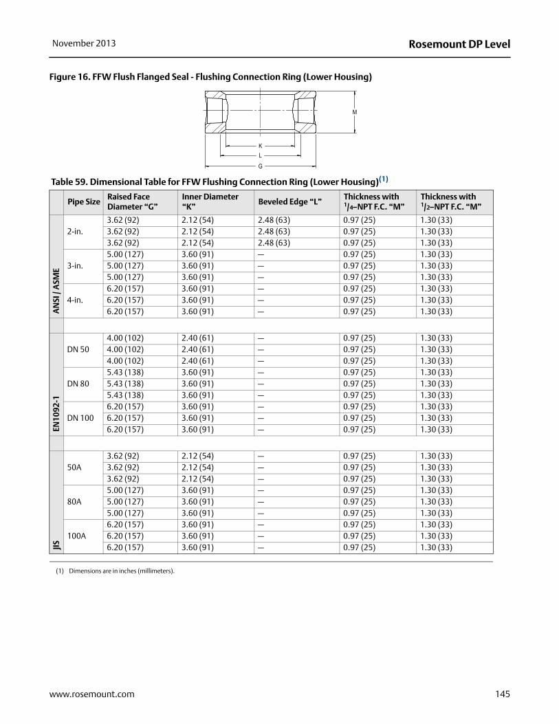
Rosemount DP LevelNovember 2013
145www.rosemount.com
Figure 16. FFW Flush Flanged Seal - Flushing Connection Ring (Lower Housing)
Table 59. Dimensional Table for FFW Flushing Connection Ring (Lower Housing)(1)
(1) Dimensions are in inches (millimeters).
Pipe SizeRaised Face Diameter “G”
Inner Diameter “K”
Beveled Edge “L”Thickness with 1/4–NPT F.C. “M”
Thickness with 1/2–NPT F.C. “M”
AN
SI /
ASM
E
2-in.3.62 (92) 2.12 (54) 2.48 (63) 0.97 (25) 1.30 (33)3.62 (92) 2.12 (54) 2.48 (63) 0.97 (25) 1.30 (33)3.62 (92) 2.12 (54) 2.48 (63) 0.97 (25) 1.30 (33)
3-in.5.00 (127) 3.60 (91) — 0.97 (25) 1.30 (33)5.00 (127) 3.60 (91) — 0.97 (25) 1.30 (33)5.00 (127) 3.60 (91) — 0.97 (25) 1.30 (33)
4-in.6.20 (157) 3.60 (91) — 0.97 (25) 1.30 (33)6.20 (157) 3.60 (91) — 0.97 (25) 1.30 (33)6.20 (157) 3.60 (91) — 0.97 (25) 1.30 (33)
EN10
92-1
DN 504.00 (102) 2.40 (61) — 0.97 (25) 1.30 (33)4.00 (102) 2.40 (61) — 0.97 (25) 1.30 (33)4.00 (102) 2.40 (61) — 0.97 (25) 1.30 (33)
DN 805.43 (138) 3.60 (91) — 0.97 (25) 1.30 (33)5.43 (138) 3.60 (91) — 0.97 (25) 1.30 (33)5.43 (138) 3.60 (91) — 0.97 (25) 1.30 (33)
DN 1006.20 (157) 3.60 (91) — 0.97 (25) 1.30 (33)6.20 (157) 3.60 (91) — 0.97 (25) 1.30 (33)6.20 (157) 3.60 (91) — 0.97 (25) 1.30 (33)
JIS
50A3.62 (92) 2.12 (54) — 0.97 (25) 1.30 (33)3.62 (92) 2.12 (54) — 0.97 (25) 1.30 (33)3.62 (92) 2.12 (54) — 0.97 (25) 1.30 (33)
80A5.00 (127) 3.60 (91) — 0.97 (25) 1.30 (33)5.00 (127) 3.60 (91) — 0.97 (25) 1.30 (33)5.00 (127) 3.60 (91) — 0.97 (25) 1.30 (33)
100A6.20 (157) 3.60 (91) — 0.97 (25) 1.30 (33)6.20 (157) 3.60 (91) — 0.97 (25) 1.30 (33)6.20 (157) 3.60 (91) — 0.97 (25) 1.30 (33)
M
LK
G

Rosemount DP Level November 2013
g ter
7)
7)
7)7)7)3)3)3)
8)
8)
7)7)7)0)1)1)0)
Figure 17. RFW Flanged Seal Standard Design
Table 60. RFW Flanged Seal Standard Design Dimensions(1)(2)
Pipe Size ClassFlange Diameter “A”
Flange Thickness “B”
Overall Height “C”Bolt Circle Diameter “D”
Bolt Hole Diameter “E”
Lower HousinDiame“F”
No or 1/4-in. NPT flush connection
1/2-in. NPT flush connection
AN
SI /
ASM
E
1/2-in. 2500 lb. 5.25 (133) 1.19 (30) 2.45 (62) 2.79 (71) 3.50 (89) 0.88 (22) 2.62 (6
3/4-in.300/600 lb.
4.62 (117) 0.62 (16) 2.45 (62) 2.79 (71) 3.25 (83) 0.75 (19) 2.62 (6
1-in.150 lb. 4.25 (108) 0.50 (13) 2.45 (62) 2.79 (71) 3.12 (79) 0.63 (16) 2.62 (6300 lb. 4.88 (124) 0.62 (16) 2.45 (62) 2.79 (71) 3.50 (89) 0.75 (19) 2.62 (6600 lb. 4.88 (124) 0.69 (18) 2.45 (62) 2.79 (71) 3.50 (89) 0.75 (19) 2.62 (6
11/2-in. 150 lb. 5.00 (127) 0.62 (16) 2.45 (62) 2.79 (71) 3.88 (99) 0.63 (16) 2.88 (7300 lb. 6.12 (155) 0.75 (19) 2.45 (62) 2.79 (71) 4.50 (114) 0.88 (22) 2.88 (7600 lb. 6.12 (155) 0.88 (22) 2.45 (62) 2.79 (71) 4.50 (114) 0.88 (22) 2.88 (7
EN 1
092-
1 DN 25 PN 40 4.53 (115) 0.71 (18) 2.45 (62) 2.79 (71) 3.35 (85) 0.55 (14) 2.68 (6
DN 40 PN 40 5.91 (150) 0.71 (18) 2.45 (62) 2.79 (71) 4.33 (110) 0.71 (18) 3.47 (8
JIS
20A 40K 4.72 (120) 0.79 (20) 2.45 (62) 2.79 (71) 3.35 (85) 0.75 (19) 2.62 (6
25A10K 4.92 (125) 0.55 (14) 2.45 (62) 2.79 (71) 3.54 (90) 0.75 (19) 2.62 (620K 4.92 (125) 0.63 (16) 2.45 (62) 2.79 (71) 3.54 (90) 0.75 (19) 2.62 (640K 5.12 (130) 0.87 (22) 2.45 (62) 2.79 (71) 3.74 (95) 0.75 (19) 2.76 (7
40A10K 5.51 (140) 0.63 (16) 2.45 (62) 2.79 (71) 4.13 (105) 0.75 (19) 3.19 (820K 5.51 (140) 0.71 (18) 2.45 (62) 2.79 (71) 4.13 (105) 0.75 (19) 3.19 (840K 6.30 (160) 0.94 (24) 2.45 (62) 2.79 (71) 4.72 (120) 0.91 (23) 3.54 (9
(1) Dimensions are in inches (millimeters).
(2) Lower housing is loose on standard design, consult factory for retained lower housing options.
Process Flange
Diaphragm
Lower Housing or Flushing Connection
146 www.rosemount.com

Rosemount DP LevelNovember 2013
147www.rosemount.com
Figure 18. RFW Flanged Seal Stud Bolt Design
Table 61. RFW Flanged Seal Stud Bolt Design Dimensions(1)
(1) Upper and lower housing installed bolt torque with CS or SST bolts is 23 ft-lbs. (31 Nm).
Pipe Size Class Overall Height “A”Stud Circle Diameter “B”
Stud (Size, Length) “C”
Lower Housing Diameter “D”
Raised Face Diameter “E”
No or 1/4-in. NPT flush connection
1/2-in. NPT flush connection
AN
SI /
ASM
E 1/2-in. 150 lb. 2.52 (64) 2.82 (72) 2.38 (61) 1/2-13NC, 2.5-in. 3.74 (95) 1.38 (35)
1/2-in. 300/600 lb.
2.77 (70) 2.87 (73) 2.62 (67) 1/2-13NC, 2.5-in. 3.75 (95) 1.38 (35)
3/4-in. 150 lb. 2.52 (64) 2.82 (72) 2.75 (70) 1/2-13NC, 2.5-in. 3.88 (99) 1.69 (43)
EN 1
092-
1 DN 15 PN 40 2.52 (64) 2.82 (72) 2.56 (65) M12x1.75, 60mm 3.74 (95) 1.77 (45)
DN 15PN 100/160
2.52 (64) 2.82 (72) 2.95 (75) M12x1.75, 60mm 4.13 (105) 1.77 (45)
DN 20 PN 40 2.52 (64) 2.82 (72) 2.95 (75) M12x1.75, 60mm 4.13 (105) 2.28 (58)
JIS
10A10K 2.52 (64) 2.82 (72) 2.56 (65) M12x1.75,60mm 3.74 (95) 1.81 (46)20K 2.52 (64) 2.82 (72) 2.56 (65) M12x1.75,60mm 3.74 (95) 1.81 (46)40K 2.52 (64) 2.82 (72) 2.95 (75) M16x2.00,70mm 4.33 (110) 2.05 (52)
15A10K 2.52 (64) 2.82 (72) 2.76 (70) M12x1.75,60mm 3.74 (95) 2.01 (51)20K 2.52 (64) 2.82 (72) 2.76 (70) M12x2.00,60mm 3.74 (95) 2.01 (51)40K 2.52 (64) 2.82 (72) 3.15 (80) M16x2.00,70mm 4.53 (115) 2.17 (55)
20A10K 2.52 (64) 2.82 (72) 2.95 (75) M12x1.75,60mm 3.94 (100) 2.21 (56)20K 2.52 (64) 2.82 (72) 2.95 (75) M12x1.75,60mm 3.94 (100) 2.21 (56)
Upper Housing
Diaphragm
Lower Housing or Flushing Connection
Bolts

Rosemount DP Level November 2013
148 www.rosemount.com
Figure 19. EFW Extended Flanged Seal - Extended Flanged Assembly
Table 62. EFW Extended Flanged Seal Dimensions(1)
(1) Dimensions are in inches (millimeters).
Pipe Size ClassFlange Diameter “A”
Flange Thickness “B”
Bolt Circle “C”# of Bolts
Bolt Hole Diameter “D”
Raised Face Diameter “F”
AN
SI /
ASM
E
11/2-in.150 lb. 5.00 (127) 0.62 (16) 3.88 (99) 4 0.63 (16) 2.88 (73)300 lb. 6.12 (156) 0.75 (19) 4.50 (114) 4 0.88 (22) 2.88 (73)600 lb. 6.12 (156) 0.88 (22) 4.50 (114) 4 0.88 (22) 2.88 (73)
2-in.150 lb. 6.00 (152) 0.69 (18) 4.75 (121) 4 0.75 (19) 3.62 (92)300 lb. 6.50 (165) 0.82 (21) 5.00 (127) 8 0.75 (19) 3.62 (92)600 lb. 6.50 (165) 1.00 (25) 5.00 (127) 8 0.75 (19) 3.62 (92)
3-in.150 lb. 7.50 (191) 0.88 (22) 6.00 (152) 4 0.75 (19) 5.00 (127)300 lb. 8.25 (210) 1.06 (27) 6.62 (168) 8 0.88 (22) 5.00 (127)600 lb. 8.25 (210) 1.25 (32) 6.62 (168) 8 0.88 (22) 5.00 (127)
4-in.150 lb. 9.00 (229) 0.88 (22) 7.50 (191) 8 0.75 (19) 6.20 (158)300 lb. 10.00 (254) 1.19 (30) 7.88 (200) 8 0.88 (22) 6.20 (158)600 lb. 10.75 (273) 1.50 (38) 8.50 (216) 8 1.00 (25) 6.20 (158)
EN 1
092-
1
DN 50PN 40 6.50 (165) 0.79 (20) 4.92 (125) 4 0.71 (18) 4.02 (102)PN 63 7.08 (180) 1.02 (26) 5.31 (135) 4 0.87 (22) 4.02 (102)PN 100 7.68 (195) 1.10 (28) 5.71 (145) 4 1.02 (26) 4.02 (102)
DN 80PN 40 7.87 (200) 0.94 (24) 6.30 (160) 8 0.71 (18) 5.43 (138) PN 63 8.46 (215) 1.10 (28) 6.69 (170) 8 0.88 (22) 5.43 (138) PN 100 9.06 (230) 1.26 (32) 7.09 (180) 8 1.02 (26) 5.43 (138)
DN 100PN 16 8.66 (220) 0.79 (20) 7.09 (180) 8 0.71 (18) 6.20 (158)PN 40 9.25 (235) 0.94 (24) 7.48 (190) 8 0.87 (22) 6.20 (158)PN 63 9.84 (250) 1.18 (30) 7.87 (200) 8 1.02 (26) 6.20 (158)
JIS
50A10K 6.10 (155) 0.63 (16) 4.72 (120) 4 0.75 (19) 3.62 (92)20K 6.10 (155) 0.71 (18) 4.72 (120) 8 0.75 (19) 3.62 (92)40K 6.50 (165) 1.02 (26) 5.12 (130) 8 0.75 (19) 4.00 (102)
80A10K 7.28 (185) 0.71 (18) 5.91 (150) 8 0.75 (19) 5.00 (127)20K 7.87 (200) 0.87 (22) 6.30 (160) 8 0.91 (23) 5.00 (127)40K 8.27 (210) 1.26 (32) 6.69 (170) 8 0.91 (23) 5.43 (138)
100A10K 8.27 (210) 0.71 (18) 6.89 (175) 8 0.75 (19) 6.20 (158)20K 8.86 (225) 0.94 (24) 7.28 (185) 8 0.91 (23) 6.20 (158)40K 9.84 (250) 1.42 (36) 8.07 (205) 8 0.98 (25) 6.20 (158)
Process Flange
Extension
Diaphragm

Rosemount DP LevelNovember 2013
Process Connection Size(1)
Diameter “E”ANSI B16.5 EN 1092-1 JIS B2238
3-in. DN 80 80A 2.58 (66)4-in. DN 100 100A 3.50 (89)1 ½-in. DN 40 40A 1.45 (37)2-in. DN 50 50A 1.90 (48)3-in. Headbox DN 80 Headbox — 2.88 (73)4-in. Headbox DN100 Headbox — 3.78 (96)
(1) Dimensions are in inches (millimeters).
149www.rosemount.com

Rosemount DP Level November 2013
Figure 20. PFW Pancake Seal
Table 63. PFW Pancake Seal Dimensions(1)
Pipe Size
ClassFlange Diameter “A”
Flange Thickness “B”
# of Bolts
Bolt Circle“C”
Bolt Hole Diameter “D”
Standard Diaphragm Diameter “F”
AN
SI /
ASM
E
2-in.
150 lb. 6.00 (152) 0.69 (18) 4 4.75 (121) 0.75 (19) 2.30 (58)300 lb. 6.50 (165) 0.81 (21) 8 5.00 (127) 0.75 (19) 2.30 (58)600 lb. 6.50 (165) 1.00 (25) 8 5.00 (127) 0.75 (19) 2.30 (58)900/1500 lb.
8.50 (216) 1.50 (38) 8 6.50 (165) 1.00 (25) 2.30 (58)
2500 lb. 9.25 (235) 2.00 (51) 8 6.75 (172) 1.13 (29) 2.30 (58)
3-in.
150 lb. 7.50 (191) 0.88 (22) 4 6.00 (152) 0.75 (19) 3.50 (89)300 lb. 8.25 (210) 1.06 (27) 8 6.62 (168) 0.88 (22) 3.50 (89)600 lb. 8.25 (210) 1.25 (32) 8 6.62 (168) 0.88 (22) 3.50 (89)900 lb. 10.50 (267) 1.50 (38) 8 8.00 (203) 1.25 (32) 3.50 (89)1500 lb. 10.50 (267) 1.88 (48) 8 8.00 (203) 1.25 (32) 3.50 (89)2500 lb 12.00 (305) 2.62 (67) 8 9.00 (229) 1.38 (35) 3.50 (89)
EN10
92-1
DN 50
PN 40 6.50 (165) 0.67 (17) 4 4.92 (125) 0.71 (18) 2.30 (58)PN 63 7.09 (180) 0.91 (23) 4 5.31 (135) 0.87 (22) 2.30 (58)PN 100 7.68 (195) 0.98 (25) 4 5.71 (145) 1.10 (28) 2.30 (58)
DN 80
PN 40 7.87 (200) 0.83 (21) 8 6.30 (160) 0.71 (18) 3.50 (89)PN 63 8.46 (215) 0.98 (25) 8 6.69 (170) 0.87 (22) 3.50 (89)PN 100 9.06 (230) 0.98 (25) 8 7.09 (180) 1.10 (28) 3.50 (89)
(1) Dimensions are in inches (millimeters).
FLUSHING CONNECTION
Process Flange
Flushing Connection
Diaphragm
150 www.rosemount.com

Rosemount DP LevelNovember 2013
Pipe SizeOuter Diameter “G”
Inner Diameter “K”
Beveled Diameter “L”
Thickness with 1/4-NPT F.C. “M”
Thickness with 1/2-NPT F.C. “M”
Minimum Gasket I.D. “N”
AN
SI /
ASM
E
2-in.
3.62 (92) 2.12 (54) 2.48 (63) 0.97 (25) 1.30 (33) 2.62 (67)3.62 (92) 2.12 (54) 2.48 (63) 0.97 (25) 1.30 (33) 2.62 (67)3.62 (92) 2.12 (54) 2.48 (63) 0.97 (25) 1.30 (33) 2.62 (67)3.62 (92) 2.12 (54) — 0.97 (25) 1.30 (33) 2.62 (67)3.62 (92) 2.12 (54) — 0.97 (25) 1.30 (33) 2.62 (67)
3-in.
5.00 (127) 3.60 (91) — 0.97 (25) 1.30 (33) 3.82 (97)5.00 (127) 3.60 (91) — 0.97 (25) 1.30 (33) 3.82 (97)5.00 (127) 3.60 (91) — 0.97 (25) 1.30 (33) 3.82 (97)5.00 (127) 3.60 (91) — 0.97 (25) 1.30 (33) 2.82 (97)5.00 (127) 3.60 (91) — 0.97 (25) 1.30 (33) 2.82 (97)5.00 (127) 3.60 (91) — 0.97 (25) 1.30 (33) 2.82 (97)
EN10
92-1 DN 50
4.00 (102) 2.40 (61) — 0.97 (25) 1.30 (33) 2.62 (67)4.00 (102) 2.40 (61) — 0.97 (25) 1.30 (33) 2.62 (67)4.00 (102) 2.40 (61) — 0.97 (25) 1.30 (33) 2.62 (67)
DN 805.43 (138) 3.60 (91) — 0.97 (25) 1.30 (33) 3.82 (97)5.43 (138) 3.60 (91) — 0.97 (25) 1.30 (33) 3.82 (97)5.43 (138) 3.60 (91) — 0.97 (25) 1.30 (33) 3.82 (97)
151www.rosemount.com

Rosemount DP Level November 2013
Figure 21. FCW Flush Flanged Seal – Ring Type Joint (RTJ) Gasket Surface Two-Piece Design (shown with flushing ring)
Process Flange
Flushing Connection
Diaphragm
Table 64. Dimensional Table for FCW 2-Piece Flange Type Flush Diaphragm Seal(1)
AN
SI /
ASM
E
Pipe Size ClassFlange Diameter “A”
Flange Thickness “B”
Bolt Circle Diameter “C”
Bolt Hole Diameter “D”
Overall Height “H”
Raised Face Height “J”
2-in.
150 lb. 6.00 (152) 0.69 (18) 4.75 (121) 0.75 (19) 2.43 (62) 0.68 (17)300 lb. 6.50 (165) 0.82 (21) 5.00 (127) 0.75 (19) 2.43 (62) 0.68 (17)600 lb. 6.50 (165) 1.00 (25) 5.00 (127) 0.75 (19) 2.43 (62) 0.68 (17)1500 lb. 8.50 (216) 1.50 (38) 6.50 (165) 1.00 (25) 2.57 (65) 0.82 (21)2500 lb. 9.25 (235) 2.00 (51) 6.75 (171) 1.14 (29) 3.07 (78) 0.82 (21)
3-in.
150 lb. 7.50 (191) 0.88 (22) 6.00 (152) 0.75 (19) 2.43 (62) 0.68 (17)300 lb. 8.25 (210) 1.06 (27) 6.62 (168) 0.88 (22) 2.43 (62) 0.68 (17)600 lb. 8.25 (210) 1.25 (32) 6.62 (168) 0.88 (22) 2.43 (62) 0.68 (17)900 lb. 9.50 (241) 1.50 (38) 7.50 (191) 1.00 (25) 2.57 (65) 0.82 (21)1500 lb. 10.50 (267) 1.88 (48) 8.00 (203) 1.25 (32) 3.07 (78) 0.82 (21)2500 lb. 12.00 (305) 2.62 (67) 9.00 (229) 1.38 (35) 4.07 (103) 0.82 (21)
(1) Dimensions are in inches (millimeters).
AN
SI /
ASM
E
Pipe SizeRTJ Diameter “E”
Diaphragm Diameter “F”
Raised Face Diameter “G”
Inner Diameter “K”
Thickness with 1/4-NPT F.C. “L”
Thickness with 1/2-NPT F.C. “L”
2-in.
3.25 (83) 2.30 (58) 4.00 (102) 2.12 (54) 1.40 (36) 1.70 (43)3.25 (83) 2.30 (58) 4.25 (108) 2.12 (54) 1.40 (36) 1.70 (43)3.25 (83) 2.30 (58) 4.25 (108) 2.12 (54) 1.40 (36) 1.70 (43)3.75 (95) 2.30 (58) 4.88 (124) 2.12 (54) 1.40 (36) 1.70 (43)4.00 (102) 3.50 (89) 5.25 (133) 2.12 (54) 1.40 (36) 1.70 (43)
3-in.
4.50 (114) 3.50 (89) 5.25 (133) 3.60 (91) 1.50 (38) 1.80 (46)4.88 (124) 3.50 (89) 5.75 (146) 3.60 (91) 1.50 (38) 1.80 (46)4.88 (124) 3.50 (89) 5.75 (146) 3.60 (91) 1.50 (38) 1.80 (46)4.88 (124) 3.50 (89) 6.12 (155) 3.60 (91) 1.50 (38) 1.80 (46)5.38 (137) 3.50 (89) 6.62 (168) 3.60 (91) 1.50 (38) 1.80 (46)5.00 (127) 3.50 (89) 6.62 (168) 3.60 (91) 1.50 (38) 1.80 (46)
152 www.rosemount.com

Rosemount DP LevelNovember 2013
T
n
Figure 22. RCW Flanged Remote Seal Ring Type Joint (RTJ) and Flushing Connection Ring
Table 65. RCW Flanged Remote Seal Dimensions(1)
(1) Dimensions are in inches (millimeters).
Pipe Size
ClassFlange Diameter “A”
Flange Thickness “B”
Bolt Circle Diameter “C”
Bolt Hole Diameter “D”
Lower Housing Inner Diameter “E”
RTJ Groove Diameter “F”
Lower Housing Outer Diameter “G”
Overall Height “H”
AN
SI /
ASM
E
No or 1/4-in. NPT
flush connection
1/2-in. NPflush
connectio
1/2-in. 2500 lb. 5.25 (133) 1.19 (30) 3.50 (89) 0.88 (22) 0.62 (16) 1.69 (43) 2.64 (67) 2.88 (73) 3.18 (81)
3/4-in.300/600 lb.
4.62 (117) 0.62 (16) 3.25 (83) 0.75 (19) 0.82 (21) 1.69 (43) 2.64 (67) 2.88 (73) 3.18 (81)
3/4-in.900/1500 lb.
5.12 (130) 1.00 (25) 3.50 (89) 0.88 (22) 0.82 (21) 1.75 (45) 2.64 (67) 2.88 (73) 3.18 (81)
3/4-in. 2500 lb. 5.50 (140) 1.25 (32) 3.75 (95) 0.88 (22) 0.82 (21) 2.00 (51) 2.90 (74) 2.88 (73) 3.18 (81)1-in. 150 lb. 4.25 (108) 0.50 (13) 3.12 (79) 0.63 (16) 1.05 (27) 1.88 (48) 2.64 (67) 2.88 (73) 3.18 (81)1-in. 300 lb. 4.88 (124) 0.62 (16) 3.50 (89) 0.75 (19) 1.05 (27) 2.00 (51) 2.77 (70) 2.88 (73) 3.18 (81)1-in. 600 lb. 4.88 (124) 0.69 (18) 3.50 (89) 0.75 (19) 1.05 (27) 2.00 (51) 2.77 (70) 2.88 (73) 3.18 (81)
1-in.900/1500 lb.
5.88 (149) 1.12 (29)4.00 (102)
1.00 (25) 1.05 (27) 2.00 (51) 2.83 (72) 2.88 (73) 3.18 (81)
1-in. 2500 lb. 6.25 (159) 1.38 (35)4.25 (108)
1.00 (25) 1.05 (27) 2.38 (60) 3.27 (83) 2.88 (73) 3.18 (81)
11/2-in. 150 lb. 5.00 (127) 0.62 (16) 3.88 (98) 0.63 (16) 1.61 (41) 2.56 (65) 3.27 (83) 2.88 (73) 3.18 (81)
11/2-in. 300 lb. 6.12 (156) 0.75 (19)4.50 (114)
0.88 (22) 1.61 (41) 2.69 (68) 3.58 (91) 2.88 (73) 3.18 (81)
11/2-in. 600 lb. 6.12 (156) 0.88 (22)4.50 (114)
0.88 (22) 1.61 (41) 2.69 (68) 3.58 (91) 2.88 (73) 3.18 (81)
11/2-in.900/1500 lb.
7.00 (178) 1.25 (32)4.88 (124)
1.12 (28) 1.61 (41) 2.69 (68) 3.64 (93) 2.88 (73) 3.18 (81)
11/2-in. 2500 lb. 8.00 (203) 1.75 (45)5.75 (146)
1.25 (32) 1.61 (41) 3.25 (83)4.52 (115)
2.88 (73) 3.18 (81)
Process Flange
Flushing Connection
Diaphragm
153www.rosemount.com
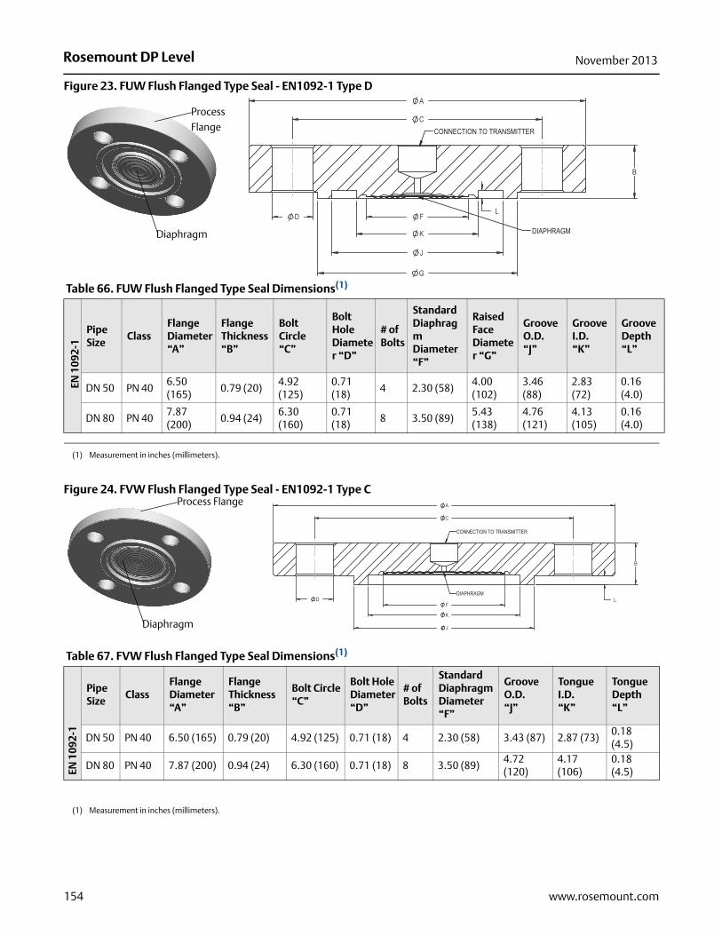
Rosemount DP Level November 2013
154 www.rosemount.com
Figure 23. FUW Flush Flanged Type Seal - EN1092-1 Type D
Figure 24. FVW Flush Flanged Type Seal - EN1092-1 Type C
Table 66. FUW Flush Flanged Type Seal Dimensions(1)
(1) Measurement in inches (millimeters).
EN 1
092-
1
Pipe Size
ClassFlange Diameter“A”
Flange Thickness “B”
Bolt Circle“C”
Bolt Hole Diameter “D”
# of Bolts
Standard DiaphragmDiameter “F”
Raised Face Diameter “G”
Groove O.D. “J”
Groove I.D.“K”
Groove Depth“L”
DN 50 PN 406.50 (165)
0.79 (20)4.92 (125)
0.71 (18)
4 2.30 (58)4.00 (102)
3.46 (88)
2.83 (72)
0.16 (4.0)
DN 80 PN 407.87 (200)
0.94 (24)6.30 (160)
0.71 (18)
8 3.50 (89)5.43 (138)
4.76 (121)
4.13 (105)
0.16 (4.0)
Process Flange
Diaphragm
Process Flange
Diaphragm
Table 67. FVW Flush Flanged Type Seal Dimensions(1)
EN 1
092-
1
Pipe Size
ClassFlange Diameter“A”
Flange Thickness “B”
Bolt Circle“C”
Bolt Hole Diameter “D”
# of Bolts
Standard DiaphragmDiameter “F”
Groove O.D. “J”
Tongue I.D.“K”
Tongue Depth“L”
DN 50 PN 40 6.50 (165) 0.79 (20) 4.92 (125) 0.71 (18) 4 2.30 (58) 3.43 (87) 2.87 (73)0.18 (4.5)
DN 80 PN 40 7.87 (200) 0.94 (24) 6.30 (160) 0.71 (18) 8 3.50 (89)4.72 (120)
4.17 (106)
0.18 (4.5)
(1) Measurement in inches (millimeters).

Rosemount DP LevelNovember 2013
Figure 25. RTW Threaded Seal
Table 68. RTW Threaded Seal Dimensions(1)
Rating Overall Diameter 'A' Overall Height “B”
No or 1/4-in. NPT flush connection 1/2-in. NPT flush connection
2500 psi (173 bar) 3.74 (95) 2.47 (63) 2.82 (72)5000 psi (345 bar) 3.74 (95) 1.95 (50) 2.31 (59)10000 psi (690 bar) 4.00 (102) 1.95 (50) —
(1) Dimensions are in inches (millimeters).
Upper Housing
Lower Housing or Flushing Connection
Diaphragm
155www.rosemount.com
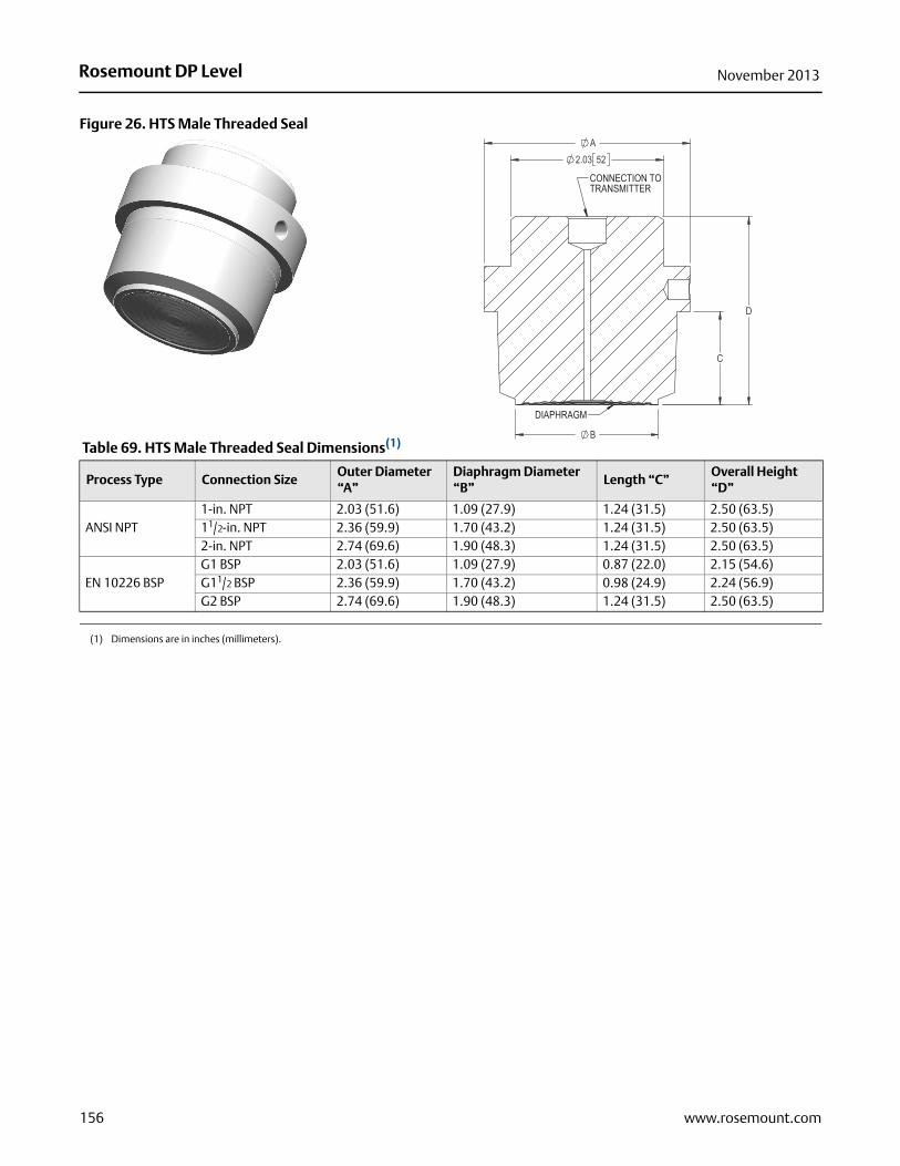
Rosemount DP Level November 2013
Figure 26. HTS Male Threaded Seal
Table 69. HTS Male Threaded Seal Dimensions(1)
(1) Dimensions are in inches (millimeters).
Process Type Connection SizeOuter Diameter “A”
Diaphragm Diameter “B”
Length “C”Overall Height “D”
ANSI NPT1-in. NPT 2.03 (51.6) 1.09 (27.9) 1.24 (31.5) 2.50 (63.5)11/2-in. NPT 2.36 (59.9) 1.70 (43.2) 1.24 (31.5) 2.50 (63.5)2-in. NPT 2.74 (69.6) 1.90 (48.3) 1.24 (31.5) 2.50 (63.5)
EN 10226 BSPG1 BSP 2.03 (51.6) 1.09 (27.9) 0.87 (22.0) 2.15 (54.6)G11/2 BSP 2.36 (59.9) 1.70 (43.2) 0.98 (24.9) 2.24 (56.9)G2 BSP 2.74 (69.6) 1.90 (48.3) 1.24 (31.5) 2.50 (63.5)
156 www.rosemount.com

Rosemount DP LevelNovember 2013
Figure 27. SCW Tri-Clamp Seal
Dimensions are in inches (millimeters)
Table 70. SCW Tri-Clamp Seal Dimensions(1)
Pipe Size Outer Diameter “A”O-rIng Groove Diameter
“B”Diaphragm Diameter
“C”
11/2-in. 2.00 (51) 1.72 (44) 1.21 (31)2-in. 2.50 (64) 2.22 (56) 1.68 (43)21/2-in. 3.05 (77) 2.78 (71) 2.07 (53)3-in. 3.58 (91) 3.28 (83) 2.58 (66)4-in. 4.68 (119) 4.35 (110) 3.66 (93)
(1) Dimensions are in inches (millimeters).
157www.rosemount.com

Rosemount DP Level November 2013
158 www.rosemount.com
Figure 15. SSW Tank Spud Seal
Figure 16. STW Hygienic Thin Wall Tank Spud Seal
Dimensions are in inches (millimeters)
Table 71. SSW Tank Spud Seal Dimensions(1)
Pipe Size Extension Length “A”
4-in. SCH 52-in. Long 2.10 (53)6-in. Long 6.10 (155)
(1) Dimensions are in inches (millimeters).
TANK SPUD

Rosemount DP LevelNovember 2013
Figure 17. EES Hygienic Flanged Tank Spud Extended Seal
Table 72. EES Hygienic Flanged Tank Spud Extended Seal Dimensions(1)
Figure 18. VCS Tri-clamp In-Line Seal
Pipe SizeFlange Diameter “A”
Flange Thickness “B”
# of BoltsBolt Circle Diameter “C”
Standard Diaphragm Diameter “D”
Extension Diameter “E”
Bolt Hole Diameter “F”
DN50 6.50 (165) 0.79 (20) 4 4.92 (125) 2.99 (76) 3.24 (82) 0.55 (14)DN80 7.87 (200) 0.94 (24) 8 6.30 (160) 4.04 (102) 4.24 (108) 0.55 (14)
159www.rosemount.com

Rosemount DP Level November 2013
160 www.rosemount.com
Table 73. VCS Tri-clamp In-Line Seal Dimensions
Figure 19. SVS Varivent Compatible Connection Seal
Figure 20. SHP Cherry-Burrell “I” Line Seal
Table 74. SHP Cherry-Burrell “I” Line Seal Dimensions(1)
Figure 21. SLS Hygienic Dairy Process Connection Female Thread Seal per DIN 11851
Pipe Size Inner Diameter “A” Groove Diameter “B” Flange Diameter “C” Outer Diameter “D”
1-in. 0.87 (22) 1.72 (44) 1.99 (51) 2.33 (59)1½-in. 1.37 (35) 1.72 (44) 1.99 (51) 2.73 (69)2-in. 1.87 (48) 2.22 (56) 2.52 (64) 3.19 (81)3-in. 2.87 (73) 3.28 (83) 3.58 (91) 4.14 (105)4-in. 3.82 (97) 4.35 (110) 4.69 (119) 5.06 (129)
Size Outer Diameter “A” Extension Diameter “B”
2-in.(1)
(1) Dimensions are in inches (millimeters).
2.64 (67) 2.24 (57)3-in. 3.88 (98) 3.31 (84)

Rosemount DP LevelNovember 2013
161www.rosemount.com
Table 75. SLS Hygienic Dairy Process Connection Female Thread Seal per DIN 11851 Dimensions
Figure 22. WSP Saddle Seal
Table 76. WSP Saddle Seal Dimensions(1)
Female Thread
Process Size / Rating
Hub Diameter “A”
“B”Thread Diameter “C”
Hub Height “D” “E”
DIN 11851
DN 40 PN 40 1.89 (48)(1)
(1) Dimensions are in inches (millimeters).
2.20 (56) Rd 65 X 1/6-in. 1.18 (30) 0.39 (10)DN 50 PN 25 2.40 (61) 2.70 (69) Rd 78 X 1/6-in. 1.22 (31) 0.43 (11)
Size Overall Height “A”Inner Diameter “B”
Outer Diameter “C”
Bolt Circle Diameter “D”
6 Bolts 8 Bolts
2-in. (1)
(1) Dimensions are in inches (millimeters).
2.72 (69) 1.50 (38) 2.50 (64) 2.99 (76) 2.91 (74)3-in. 2.46 (63) 2.01 (51) 3.02 (77) 2.99 (76) 2.91 (74)4-in. and larger 2.60 (66) 2.01 (51) 3.00 (76) 2.99 (76) 2.91 (74)
UpperHousing

Rosemount DP Level November 2013
162 www.rosemount.com
Figure 23. UCP and PMW Threaded Pipe Mount Seals
Table 77. UCP and PMW Threaded Pipe Mount Seals Dimensions(1)
Dimensions are in inches (millimeters)
SizeOverall Diameter “A”
Diameter “B”Diaphragm Diameter “C”
Sleeve Inner Diameter “D”
# of Bolts
Sleeve 1-in. Pipe 1.50 (38) 1.32 (34) 0.84 (21) 1.04 (26) 1Threaded M44 X 1.25 2.37 (60) 1.38 (35) 1.32 (32) — —
1.06
UCP
PMW
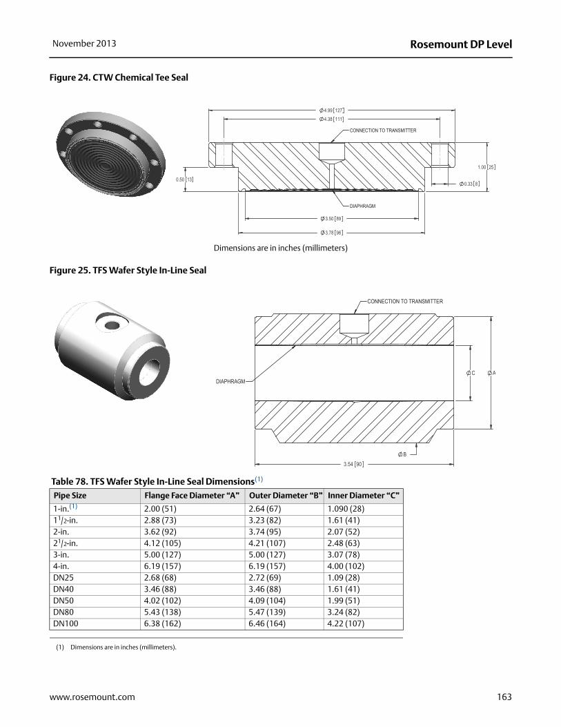
Rosemount DP LevelNovember 2013
163www.rosemount.com
Figure 24. CTW Chemical Tee Seal
Figure 25. TFS Wafer Style In-Line Seal
Table 78. TFS Wafer Style In-Line Seal Dimensions(1)
Dimensions are in inches (millimeters)
Pipe Size Flange Face Diameter “A” Outer Diameter “B” Inner Diameter “C”
1-in.(1)
(1) Dimensions are in inches (millimeters).
2.00 (51) 2.64 (67) 1.090 (28)11/2-in. 2.88 (73) 3.23 (82) 1.61 (41)2-in. 3.62 (92) 3.74 (95) 2.07 (52)21/2-in. 4.12 (105) 4.21 (107) 2.48 (63)3-in. 5.00 (127) 5.00 (127) 3.07 (78)4-in. 6.19 (157) 6.19 (157) 4.00 (102)DN25 2.68 (68) 2.72 (69) 1.09 (28)DN40 3.46 (88) 3.46 (88) 1.61 (41)DN50 4.02 (102) 4.09 (104) 1.99 (51)DN80 5.43 (138) 5.47 (139) 3.24 (82)DN100 6.38 (162) 6.46 (164) 4.22 (107)

Rosemount DP Level November 2013
Figure 26. WFW Flow-Thru Flanged Seal
Table 79. WFW Flow-Thru Flanged Seal Dimensions(1)
Dimensions are in inches (millimeters)
ClassNominal Pipe Size
Overall Length “A”
Upper to Centerline Height “B”
Bolt Circle Diameter “C”
Outside Diameter “D”
Bolt Hole Diameter “E”
Flange Thickness “F”
150 lb.1-in. 7.00 (178)(1)
(1) Dimensions are in inches (millimeters).
2.40 (61.0) 3.12 (79) 4.25 (108) 0.62 (16) 0.50 (13)2-in. 9.00 (229) 3.31 (84) 4.75 (121) 6.00 (152) 0.75 (19) 0.69 (18)3-in. 11.00 (279) 3.61 (92) 6.00 (152) 7.50 (191) 0.75 (19) 0.88 (22)
164 www.rosemount.com

Rosemount DP LevelNovember 2013
Rosemount Level Solutions
Emerson provides a complete range of Rosemount products for level measurement applications.
Pressure – Level or Interface Measurement
Flexible mounting for liquid tank levels, including those with wide temperature and pressure requirements. Can be isolated by valves. Unaffected by: vapor space changes, surface conditions, foam, corrosive fluids, internal tank equipment. Optimize performance with direct mount, Tuned-System Assemblies:
• Rosemount DP Level Transmitters and Remote Seals
• Rosemount 3051SAL, 3051L, and 2051L Liquid Level Transmitters
Vibrating Fork Switches – Point Level Detection
The Rosemount 2100 Series is developed for reliable point level detection of liquids and consists of:
• Rosemount 2110 Compact Vibrating Fork Liquid Level Switch
• Rosemount 2120 Full-featured Vibrating Fork Liquid Level Switch
Guided Wave Radar – Level and Interface Measurement
Multivariable, loop-powered Guided Wave Radar transmitters with a wide range of probe styles to fit different liquids and solids applications. The product line consists of:
• Rosemount 3300 Series – Versatile and easy-to-use transmitter with proven reliability
• Rosemount 5300 Series – Accurate, superior performance transmitter with FOUNDATION™ fieldbus support
Non-contacting Radar – Level Measurement
The Rosemount non-contacting radar family consists of:
• Rosemount 5400 Series Transmitters – Loop-powered superior performance transmitter with a wide range of antennas, for liquid level measurement in most applications and process conditions
• Rosemount 5600 Series Transmitters – Power of 4-wire give maximum sensitivity and performance for solids, challenging reactors, rapid level changes and excessive process conditions.
Non-contacting Ultrasonic – Level Measurement
The Rosemount 3100 Series ultrasonic level transmitters provide continuous non-contacting level measurement of liquids. The range consists of:
• Rosemount 3101 for simple continuous level measurement
• Rosemount 3102 for continuous measurement with two integral relays for local control functionality
• Rosemount 3105 Intrinsically safe certified version for hazardous areas
165www.rosemount.com

Standard Terms and Conditions of Sale can be found at www.rosemount.com\terms_of_saleThe Emerson logo is a trade mark and service mark of Emerson Electric Co.Rosemount and the Rosemount logotype are registered trademarks of Rosemount Inc.PlantWeb is a registered trademark of one of the Emerson Process Management group of companies.HART and WirelessHART are registered trademarks of the HART Communication FoundationModbus is a trademark of Modicon, Inc.All other marks are the property of their respective owners.© 2013 Rosemount Inc. All rights reserved.
Emerson Process ManagementRosemount Inc.8200 Market BoulevardChanhassen, MN 55317 USAT (U.S.) 1-800-999-9307T (International) (952) 906-8888F (952) 906-8889www.rosemount.com
Emerson Process ManagementBlegistrasse 23P.O. Box 1046CH 6341 BaarSwitzerlandT +41 (0) 41 768 6111F +41 (0) 41 768 6300www.rosemount.com
Emerson Process Management Asia Pacific Pte Ltd1 Pandan CrescentSignapore 128461T +65 6777 8211F +65 6777 0947Service Support Hotline: +65 6770 8711Email: [email protected]
Rosemount DP Level00813-0100-4016 Rev NA
Product Data SheetNovember 2013
Emerson Process Management Latin America1300 Concord Terrace, Suite 400Sunrise Florida 33323 USAT + 1 954 846 5030www.rosemount.com


