www.contitech.us
20
15 H
eavyw
eigh
t Co
nveyo
r Belt C
atalog
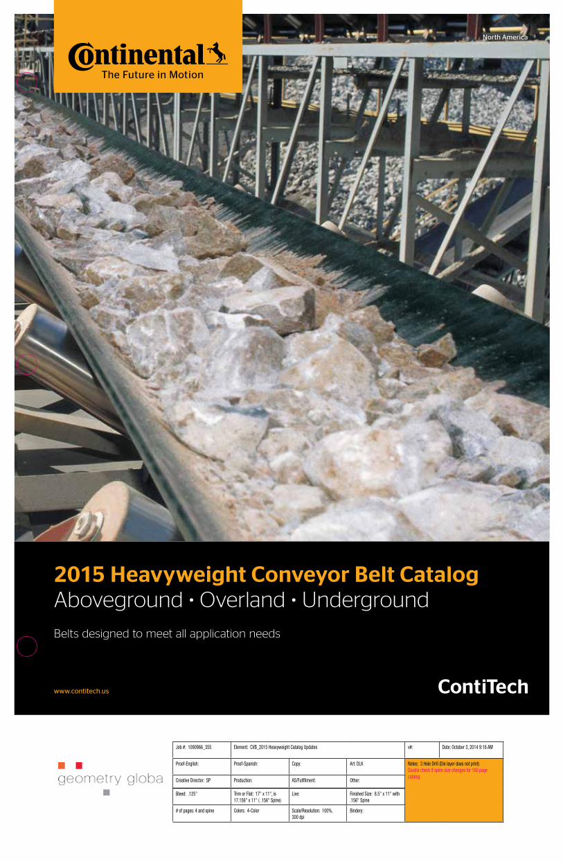
2015 Heavyweight Conveyor Belt CatalogAboveground • Overland • Underground
Belts designed to meet all application needs
North America
Job #: 1090966_355 Element: CVB_2015 Heavyweight Catalog Updates v#: Date: October 3, 2014 9:16 AM
Proof-English: Proof-Spanish: Copy: Art: DLK Notes: 3 Hole Drill (Die layer does not print)Double check if spine size changes for 100 page catalog.
Creative Director: SP Production: AS/Fullfilment: Other:
Bleed: .125" Trim or Flat: 17" x 11", is 17.156" x 11" ( .156" Spine)
Live: Finished Size: 8.5" x 11" with .156" Spine
# of pages: 4 and spine Colors: 4-Color Scale/Resolution: 100%, 300 dpi
Bindery:

20
15 H
eavyw
eigh
t Co
nveyo
r Belt C
atalog
12015 Heavyweight Conveyor Belts
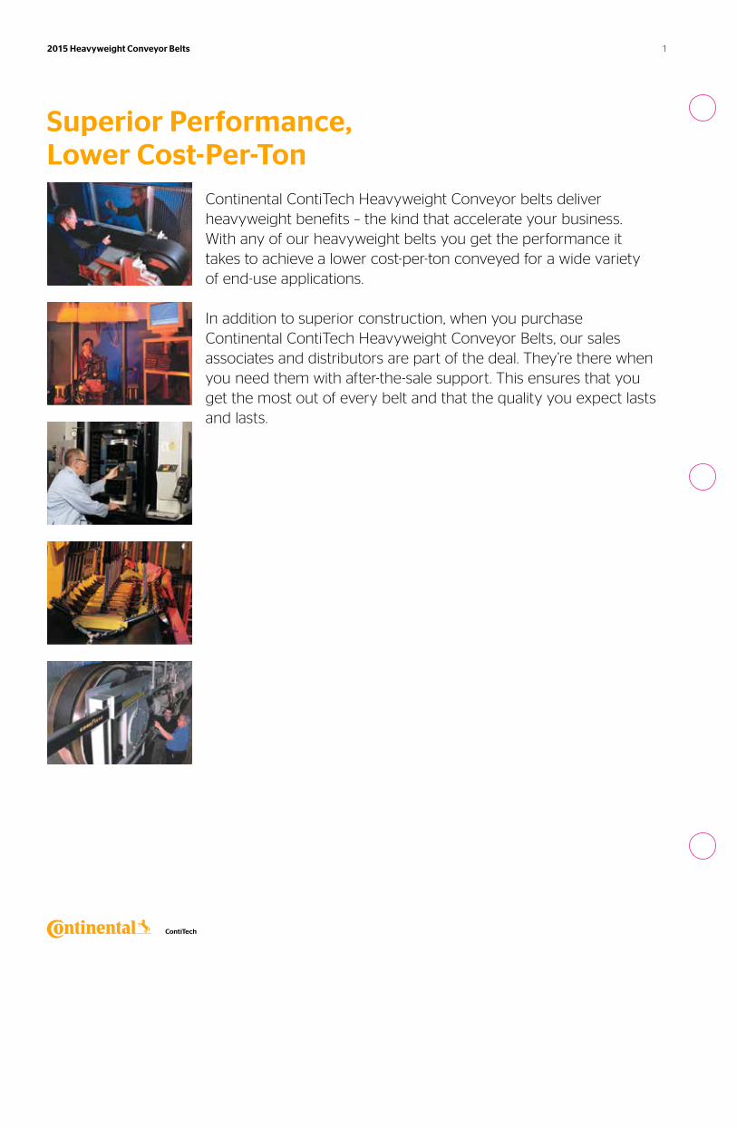
Superior Performance, Lower Cost-Per-Ton
Continental ContiTech Heavyweight Conveyor belts deliver heavyweight benefits – the kind that accelerate your business. With any of our heavyweight belts you get the performance it takes to achieve a lower cost-per-ton conveyed for a wide variety of end-use applications.
In addition to superior construction, when you purchase Continental ContiTech Heavyweight Conveyor Belts, our sales associates and distributors are part of the deal. They’re there when you need them with after-the-sale support. This ensures that you get the most out of every belt and that the quality you expect lasts and lasts.
Job #: 1090966_355 Element: CVB_2015 Heavyweight Catalog v#: 3 Date: October 3, 2014 9:03 AM
Proof-English: Proof-Spanish: Copy: Art: DLK Notes: 3 hole punch FPO. Pages 1, 2, 4, 40, 48, 56, 62, 67, 70, 78-79, 82-86 print 4-Color Process. Page 3 uses Getty Stock image #174932568, need to purchase. Page 5 uses Getty Stock image #487272915, already purchased? Page 8 & 44 - client che copy & supply new belt image. Starting on Page 9 - client to con-firm Carcass Gauge (mm) throughout. Page 14 - Need Rib image from pg 41 of '07 catalog. Page 24 - Client check if Elevator Data should be included. Page 45 - Neet Rip image from '07 catalog. Page 57 uses Getty stock image AA052493, need to purchase. Page 61 not sure if two images are stock? Page 62 - Client check-ing w/Anthony if keeping in Sensor Guard or not. Page 71 uses Getty Stock image #508905617, need to purchased. Page 82 uses 2 or 3 stock images, the first image – not sure if stock or not, very small; #173685259, #ab08883, not sure if purchased yet? Page 89 remove Olympus from photo. Page 90 has Minuteman screen shot make B/W. Page 98 - need to know if additional changes to this page?
Creative Director: SP Production: AS/Fulfilment: Other:
Bleed: .125" Trim or Flat: 24.875" x 11" Live: Finished Size: 8.5" x 11"
# of pages: 92 Colors: 2-Color Sections with 4-Color Divider pages & some additional 4-Color pages
Scale/Resolution: 100%/300 dpi
Bindery:
2 2015 Heavyweight Conveyor Belts Table of Contents
Table of Contents
Introduction
Belt Construction 4
Aboveground
Applications 6
Products
ContiTitan XP™ 7
Plylon Plus® 13
Spartan® 22
Solar-Shield® XL 750 25
Wood Sawyer® Plus 29
Wood Products Applications 34
Pathfinder® Plus 36
Underground
Products
SHIELD™ 42
Coal Quest XP® 44
Glide® Plus 49
Tough Coat PVC™ 53
Flexsteel®
Products
Flexsteel® 58
Easyrider™ 63
Preform™ 64
Pipe Conveyor Belts
Products
Confine™ 69
Underground
Cover Compounds
Performance 72
Applications 73
Total Guard™ Belt Monitoring Systems
Total Guard™ 79
Products
Cord Guard® XD 81
Cord Guard® 83
Sensor Guard® 85
Additional Information
Customer Satisfaction Activities 89
Advanced Service Tools 91
Belt Selection 92
Minuteman® Belt Analysis 93
Conveyor Belt Analysis 94
Belt Roll Diameters 95
Terms and Conditions 97
Research 98
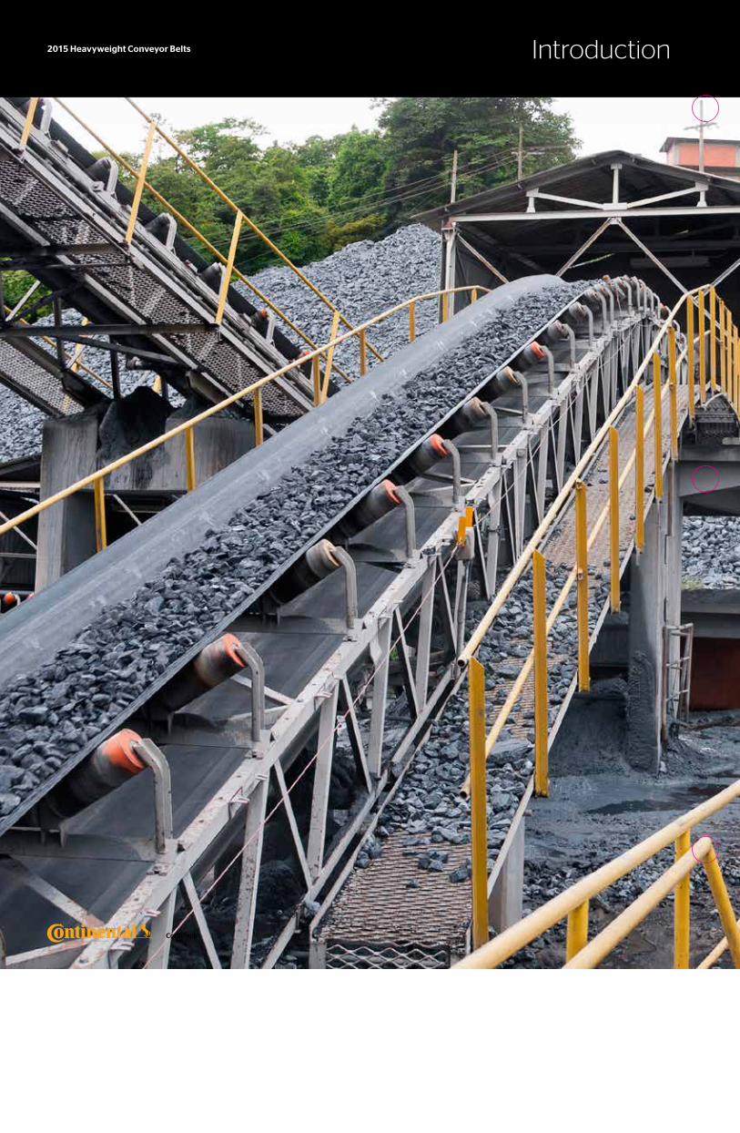
Introduction2015 Heavyweight Conveyor Belts
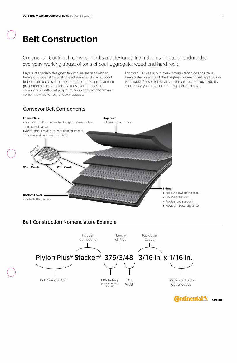
Plylon Plus® Stacker® 375/3/48 3/16 in. x 1/16 in.
Belt Construction
Number of Plies
PIW Rating (pounds per inch
of width)
Top Cover Gauge
Bottom or Pulley Cover Gauge
Rubber Compound
BeltWidth
Conveyor Belt Components
Fabric Plies
› Warp Cords - Provide tensile strength, transverse tear,
impact resistance
› Weft Cords - Provide fastener holding, impact
resistance, rip and tear resistance
Top Cover
› Protects the carcass
Skims
› Rubber between the plies
› Provide adhesion
› Provide load support
› Provide impact resistance
Bottom Cover
› Protects the carcass
Warp Cords Weft Cords
Belt Construction
Continental ContiTech conveyor belts are designed from the inside out to endure the everyday working abuse of tons of coal, aggregate, wood and hard rock.
Layers of specially designed fabric plies are sandwiched between rubber skim coats for adhesion and load support. Bottom and top cover compounds are added for maximum protection of the belt carcass. These compounds are comprised of different polymers, fillers and plasticizers and come in a wide variety of cover gauges.
For over 100 years, our breakthrough fabric designs have been tested in some of the toughest conveyor belt applications worldwide. These high-quality belt constructions give you the confidence you need for operating performance.
Lengthwise
Directio
n
Belt Construction Nomenclature Example
2015 Heavyweight Conveyor Belts Belt Construction 4
2015 Heavyweight Conveyor Belts Aboveground
6
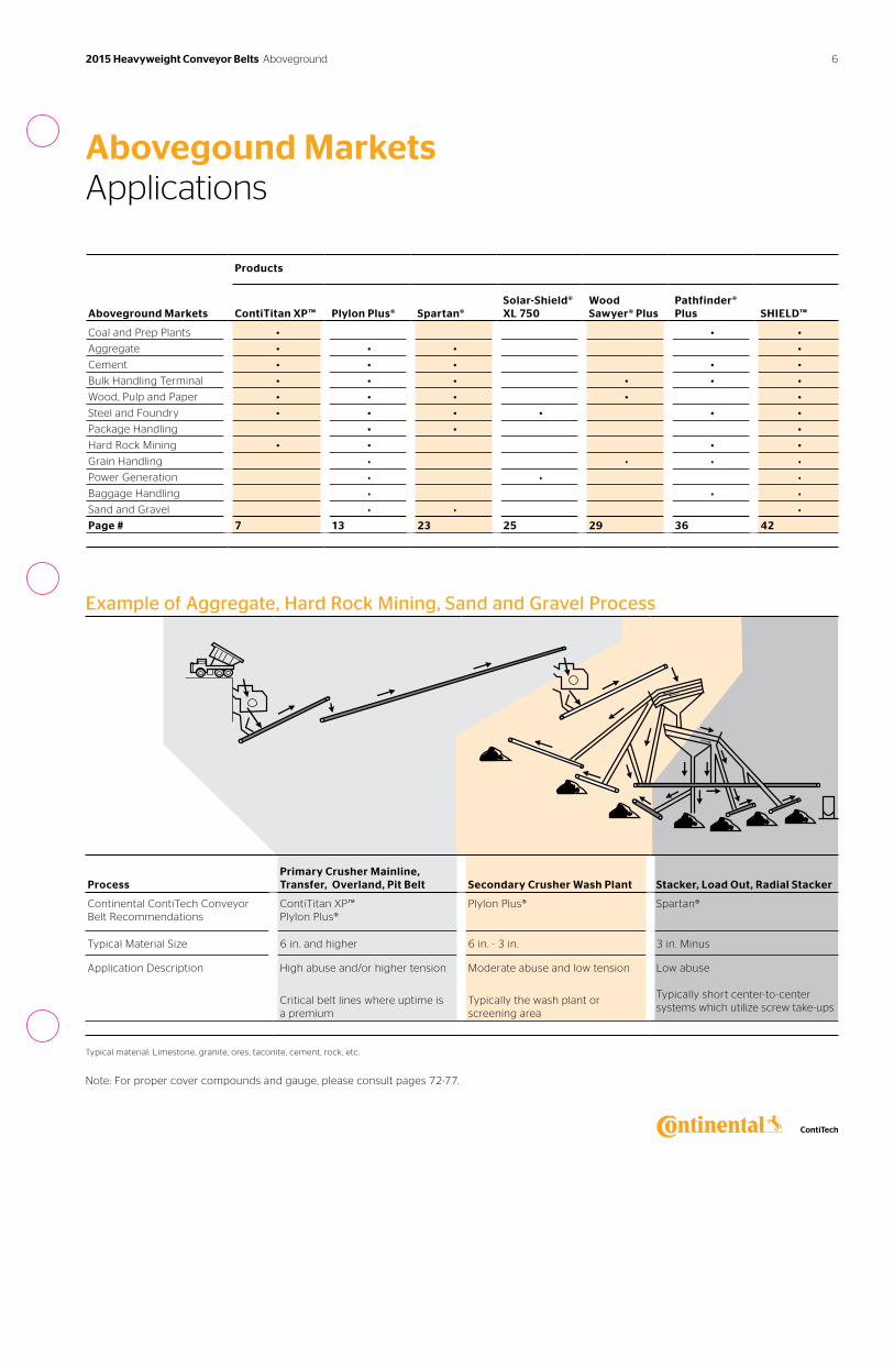
Abovegound MarketsApplications
Products
Aboveground Markets
ContiTitan XP™
Plylon Plus®
Spartan®
Solar-Shield® XL 750
Wood Sawyer® Plus
Pathfinder® Plus
SHIELD™
Coal and Prep Plants • • •
Aggregate • • • •
Cement • • • • •
Bulk Handling Terminal • • • • • •
Wood, Pulp and Paper • • • • •
Steel and Foundry • • • • • •
Package Handling • • •
Hard Rock Mining • • • •
Grain Handling • • • •
Power Generation • • •
Baggage Handling • • •
Sand and Gravel • • •
Page # 7 13 23 25 29 36 42
Example of Aggregate, Hard Rock Mining, Sand and Gravel Process
Process
Primary Crusher Mainline, Transfer, Overland, Pit Belt
Secondary Crusher Wash Plant
Stacker, Load Out, Radial Stacker
Continental ContiTech Conveyor Belt Recommendations
ContiTitan XP™ Plylon Plus®
Plylon Plus® Spartan®
Typical Material Size 6 in. and higher 6 in. - 3 in. 3 in. Minus
Application Description High abuse and/or higher tension
Critical belt lines where uptime is a premium
Moderate abuse and low tension
Typically the wash plant or screening area
Low abuse Typically short center-to-center systems which utilize screw take-ups
Typical material: Limestone, granite, ores, taconite, cement, rock, etc.
Note: For proper cover compounds and gauge, please consult pages 72-77.
2015 Heavyweight Conveyor Belts Aboveground
Features & Benefits
Innovative patented fabric weave The new dual layer twill fabric gives ContiTitan XP™ improved load bearing and impact resistance.
Exceptional impact resistance ContiTitan XP™ has industry-leading impact resistance. Loading point impact damage can be a major cause of belt failure. Design engineers used an enhanced Dynamic Impact Tester to simulate loading impact force and its effects on belting.
7
ContiTitan XP™ Belts
This rugged, fabric-reinforced conveyor belt withstands high abuse applications. It is made with a revolutionary patented Fortress™ technology weave design, holds up to the most demanding applications and delivers up to three times longer life, proving ContiTitan XP™ provides a lower cost-per-ton with unsurpassed system savings.
2015 Heavyweight Conveyor Belts ContiTitan XP™
Markets Applications Cover Compounds
› Aggregate› Cement› Coal› Foundry› Hard Rock› Pulp and Paper› Steel Production› Wood Products
› Log Debarkers› Log Decks› Mainlines› Pit Belts› Primary Crushers› Secondary Crushers› Ship Unloaders› Trash and Recycling› Any High Abuse Applications
› Defender Plus®› Stacker®› Global X®› MonsterHide™› 6740A
See pages 72-77 for more specific details.
See the process diagram for Aggregate, Hard Rock Mining, Sand and Gravel markets on page 6 for alternative belt recommendations.
Get a lower cost-per-ton conveyed Tension Range: 330 to 1250 PIW
8
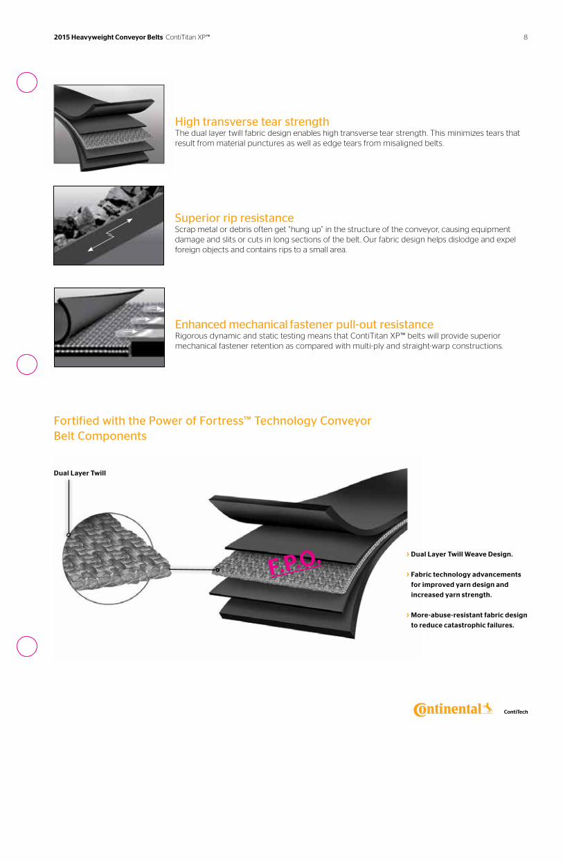
High transverse tear strength The dual layer twill fabric design enables high transverse tear strength. This minimizes tears that result from material punctures as well as edge tears from misaligned belts.
Superior rip resistance Scrap metal or debris often get “hung up” in the structure of the conveyor, causing equipment damage and slits or cuts in long sections of the belt. Our fabric design helps dislodge and expel foreign objects and contains rips to a small area.
Enhanced mechanical fastener pull-out resistance Rigorous dynamic and static testing means that ContiTitan XP™ belts will provide superior mechanical fastener retention as compared with multi-ply and straight-warp constructions.
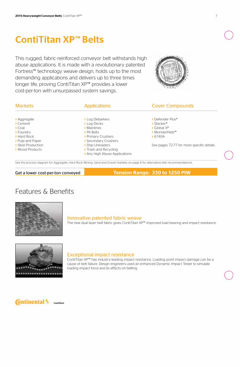
Fortified with the Power of Fortress™ Technology Conveyor Belt Components
› Dual Layer Twill Weave Design.
› Fabric technology advancements
for improved yarn design and
increased yarn strength.
› More-abuse-resistant fabric design
to reduce catastrophic failures.
Dual Layer Twill
2015 Heavyweight Conveyor Belts ContiTitan XP™
F.P.O.
9 2015 Heavyweight Conveyor Belts ContiTitan XP™
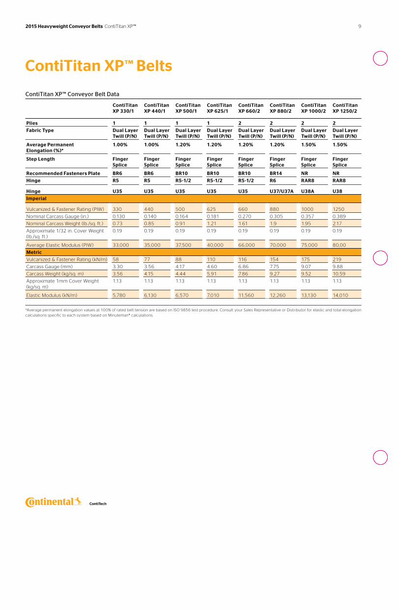
ContiTitan XP™ Conveyor Belt Data
ContiTitan XP 330/1
ContiTitan XP 440/1
ContiTitan XP 500/1
ContiTitan XP 625/1
ContiTitan XP 660/2
ContiTitan XP 880/2
ContiTitan XP 1000/2
ContiTitan XP 1250/2
Plies 1 1 1 1 2 2 2 2
Fabric Type Dual Layer Twill (P/N)
Dual Layer Twill (P/N)
Dual Layer Twill (P/N)
Dual Layer Twill (P/N)
Dual Layer Twill (P/N)
Dual Layer Twill (P/N)
Dual Layer Twill (P/N)
Dual Layer Twill (P/N)
Average Permanent Elongation (%)*
1.00% 1.00% 1.20% 1.20% 1.20% 1.20% 1.50% 1.50%
Step Length Finger Splice
Finger Splice
Finger Splice
Finger Splice
Finger Splice
Finger Splice
Finger Splice
Finger Splice
Recommended Fasteners Plate BR6 BR6 BR10 BR10 BR10 BR14 NR NR
Hinge R5 R5 R5-1/2 R5-1/2 R5-1/2 R6 RAR8 RAR8
Hinge U35 U35 U35 U35 U35 U37/U37A U38A U38
Imperial
Vulcanized & Fastener Rating (PIW) 330 440 500 625 660 880 1000 1250
Nominal Carcass Gauge (in.) 0.130 0.140 0.164 0.181 0.270 0.305 0.357 0.389
Nominal Carcass Weight (lb./sq. ft.) 0.73 0.85 0.91 1.21 1.61 1.9 1.95 2.17
Approximate 1/32 in. Cover Weight (lb./sq. ft.)
0.19 0.19 0.19 0.19 0.19 0.19 0.19 0.19
Average Elastic Modulus (PIW) 33,000 35,000 37,500 40,000 66,000 70,000 75,000 80,00
Metric
Vulcanized & Fastener Rating (kN/m) 58 77 88 110 116 154 175 219
Carcass Gauge (mm) 3.30 3.56 4.17 4.60 6.86 7.75 9.07 9.88
Carcass Weight (kg/sq. m) 3.56 4.15 4.44 5.91 7.86 9.27 9.52 10.59
Approximate 1mm Cover Weight (kg/sq. m)
1.13 1.13 1.13 1.13 1.13 1.13 1.13 1.13
Elastic Modulus (kN/m) 5,780 6,130 6,570 7,010 11,560 12,260 13,130 14,010
*Average permanent elongation values at 100% of rated belt tension are based on ISO 9856 test procedure. Consult your Sales Representative or Distributor for elastic and total elongation calculations specific to each system based on Minuteman® calculations.
ContiTitan XP™ Belts
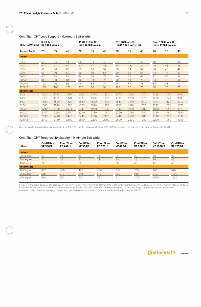
ContiTitan XP™ Load Support – Maximum Belt Width
Material Weight
0-40 lb./cu. ft. (0-640 kg/cu. m)
41-80 lb./cu. ft. (641-1280 kg/cu. m)
81-120 lb./cu. ft. (1281-1920 kg/cu. m)
Over 120 lb./cu. ft. (over 1920 kg/cu. m)
Trough Angle 20 35 45 20 35 45 20 35 45 20 35 45
Inches
330/1 60 54 54 60 54 48 54 48 42 48 42 36
440/1 60 54 54 60 54 48 54 48 42 48 42 36
550/1 66 60 60 66 60 54 60 54 54 54 48 42
625/1 66 60 60 66 60 54 60 54 54 54 48 42
660/2 90 84 84 84 78 72 84 72 66 72 66 54
880/2 96 90 84 90 84 78 90 84 78 84 78 66
1000/2 102 96 96 96 84 84 96 84 78 84 78 72
1250/2 108 108 102 102 90 90 102 90 78 90 78 78
Millimeters
330/1 1520 1370 1370 1520 1370 1220 1370 1220 1070 1220 1070 910
440/1 1520 1370 1370 1520 1370 1220 1370 1200 1070 1220 1070 910
500/1 1680 1520 1520 1680 1520 1370 1520 1370 1370 1370 1220 1070
625/1 1680 1520 1520 1680 1520 1370 1520 1370 1370 1370 1220 1070
660/2 2290 2130 2130 2130 1980 1830 2130 1830 1680 1830 1680 1370
880/2 2440 2290 2130 2290 2130 1980 2290 2130 1980 2130 1980 1680
1000/2 2590 2440 2440 2440 2130 2130 2440 2130 1980 2130 1980 1830
1250/2 2740 2750 2590 2590 2290 2290 2590 2290 1980 2290 1980 1980
On systems with troughing idler spacing greater than 5 ft. (1.5m) or idler roll gap greater than 1/2 in. (12.7mm), consult your Sales Representative or Continental ContiTech.
ContiTitan XP™ Troughability Support – Minimum Belt Width
Idlers
ContiTitan XP 330/1
ContiTitan XP 440/1
ContiTitan XP 500/1
ContiTitan XP 625/1
ContiTitan XP 660/2
ContiTitan XP 880/2
ContiTitan XP 1000/2
ContiTitan XP 1250/2
Inches
20 Degree 18 18 18 18 24 30 30 36
35 Degree 24 24 24 24 30 36 36 42
45 Degree 24 30 30 30 36 42 42 48
Millimeters
20 Degree 460 460 460 460 610 760 760 910
35 Degree 610 610 610 610 760 910 910 1070
45 Degree 610 760 750 760 910 1070 1070 1220
If top cover and pulley cover are balanced (i.e. , 3/16 in. x 3/16 in. or 4.7mm x 4.7mm) or less than 1/16 in. (1.5mm) differential (i.e. , 3/16 in. x 5/32 in. or 4.7mm x 3.9mm), add 6 in. (152mm) to the minimum belt width. 6 in. (152mm) narrower widths are possible if the belt is broken in for an extended period of time fully loaded. Consult your Sales Representative.
Additional break-in time is required when the belt has been stored prior to installation in ambient temperatures of less than 50°F (10°C).
10 2015 Heavyweight Conveyor Belts ContiTitan XP™
ContiTitan XP™ Belts
Elevator Data
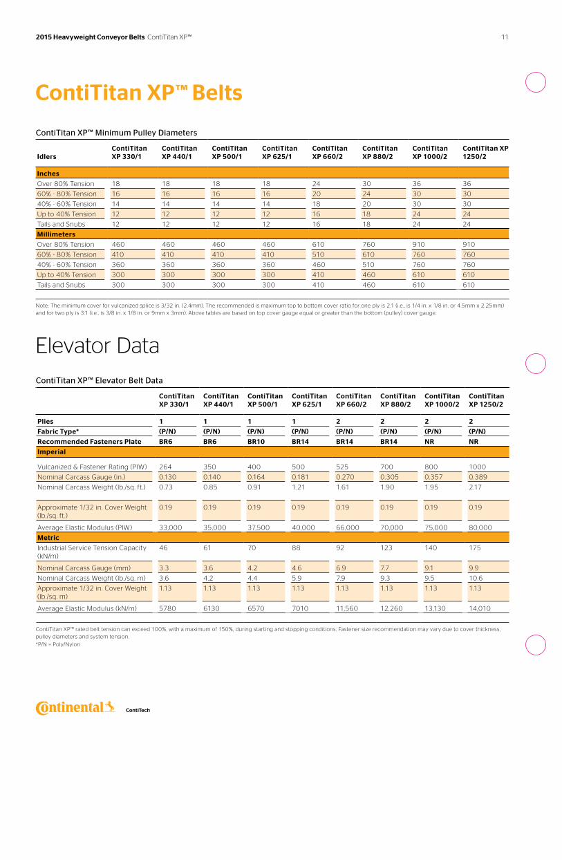
ContiTitan XP™ Minimum Pulley Diameters
Idlers
ContiTitan XP 330/1
ContiTitan XP 440/1
ContiTitan XP 500/1
ContiTitan XP 625/1
ContiTitan XP 660/2
ContiTitan XP 880/2
ContiTitan XP 1000/2
ContiTitan XP 1250/2
Inches
Over 80% Tension 18 18 18 18 24 30 36 36
60% - 80% Tension 16 16 16 16 20 24 30 30
40% - 60% Tension 14 14 14 14 18 20 30 30
Up to 40% Tension 12 12 12 12 16 18 24 24
Tails and Snubs 12 12 12 12 16 18 24 24
Millimeters
Over 80% Tension 460 460 460 460 610 760 910 910
60% - 80% Tension 410 410 410 410 510 610 760 760
40% - 60% Tension 360 360 360 360 460 510 760 760
Up to 40% Tension 300 300 300 300 410 460 610 610
Tails and Snubs 300 300 300 300 410 460 610 610
Note: The minimum cover for vulcanized splice is 3/32 in. (2.4mm). The recommended is maximum top to bottom cover ratio for one ply is 2:1 (i.e. , is 1/4 in. x 1/8 in. or 4.5mm x 2.25mm) and for two ply is 3:1 (i.e. , is 3/8 in. x 1/8 in. or 9mm x 3mm). Above tables are based on top cover gauge equal or greater than the bottom (pulley) cover gauge.
ContiTitan XP™ Elevator Belt Data
ContiTitan XP 330/1
ContiTitan XP 440/1
ContiTitan XP 500/1
ContiTitan XP 625/1
ContiTitan XP 660/2
ContiTitan XP 880/2
ContiTitan XP 1000/2
ContiTitan XP 1250/2
Plies 1 1 1 1 2 2 2 2
Fabric Type* (P/N) (P/N) (P/N) (P/N) (P/N) (P/N) (P/N) (P/N)
Recommended Fasteners Plate BR6 BR6 BR10 BR14 BR14 BR14 NR NR
Imperial
Vulcanized & Fastener Rating (PIW) 264 350 400 500 525 700 800 1000
Nominal Carcass Gauge (in.) 0.130 0.140 0.164 0.181 0.270 0.305 0.357 0.389
Nominal Carcass Weight (lb./sq. ft.) 0.73 0.85 0.91 1.21 1.61 1.90 1.95 2.17
Approximate 1/32 in. Cover Weight (lb./sq. ft.)
0.19 0.19 0.19 0.19 0.19 0.19 0.19 0.19
Average Elastic Modulus (PIW) 33,000 35,000 37,500 40,000 66,000 70,000 75,000 80,000
Metric
Industrial Service Tension Capacity (kN/m)
46 61 70 88 92 123 140 175
Nominal Carcass Gauge (mm) 3.3 3.6 4.2 4.6 6.9 7.7 9.1 9.9
Nominal Carcass Weight (lb./sq. m) 3.6 4.2 4.4 5.9 7.9 9.3 9.5 10.6
Approximate 1/32 in. Cover Weight (lb./sq. m)
1.13 1.13 1.13 1.13 1.13 1.13 1.13 1.13
Average Elastic Modulus (kN/m) 5780 6130 6570 7010 11,560 12,260 13,130 14,010
ContiTitan XP™ rated belt tension can exceed 100%, with a maximum of 150%, during starting and stopping conditions. Fastener size recommendation may vary due to cover thickness, pulley diameters and system tension.
*P/N = Poly/Nylon
11 2015 Heavyweight Conveyor Belts ContiTitan XP™
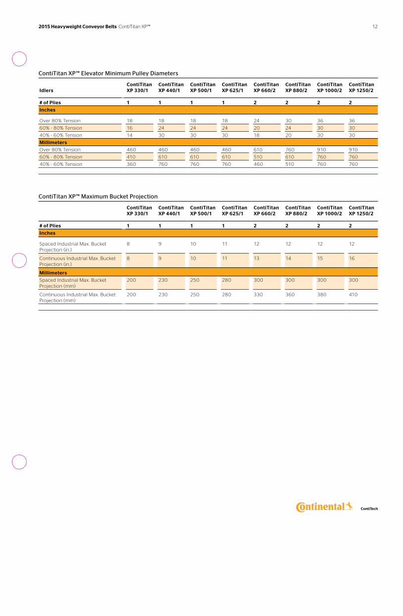
ContiTitan XP™ Elevator Minimum Pulley Diameters
Idlers
ContiTitan XP 330/1
ContiTitan XP 440/1
ContiTitan XP 500/1
ContiTitan XP 625/1
ContiTitan XP 660/2
ContiTitan XP 880/2
ContiTitan XP 1000/2
ContiTitan XP 1250/2
# of Plies 1 1 1 1 2 2 2 2
Inches
Over 80% Tension 18 18 18 18 24 30 36 36
60% - 80% Tension 16 24 24 24 20 24 30 30
40% - 60% Tension 14 30 30 30 18 20 30 30
Millimeters
Over 80% Tension 460 460 460 460 610 760 910 910
60% - 80% Tension 410 610 610 610 510 610 760 760
40% - 60% Tension 360 760 760 760 460 510 760 760
ContiTitan XP™ Maximum Bucket Projection
ContiTitan XP 330/1
ContiTitan XP 440/1
ContiTitan XP 500/1
ContiTitan XP 625/1
ContiTitan XP 660/2
ContiTitan XP 880/2
ContiTitan XP 1000/2
ContiTitan XP 1250/2
# of Plies 1 1 1 1 2 2 2 2
Inches
Spaced Industrial Max. Bucket Projection (in.)
8 9 10 11 12 12 12 12
Continuous Industrial Max. Bucket Projection (in.)
8 9 10 11 13 14 15 16
Millimeters
Spaced Industrial Max. Bucket Projection (mm)
200 230 250 280 300 300 300 300
Continuous Industrial Max. Bucket Projection (mm)
200 230 250 280 330 360 380 410
2015 Heavyweight Conveyor Belts ContiTitan XP™ 12
Markets Applications Cover Compounds
› Aggregate› Baggage Handling› Bulk Handling Terminal› Cement› Coal› Crushed Stone› Foundry› Grain› Hard Rock› Package Handling› Power Generation› Pulp and Paper› Sand and Gravel› Steel Production› Wood Products
› Coal Prep Plant› Log Debarkers› Log Decks› Mainlines› Pit Belts› Primary Crushers› Secondary Crushers› Ship Unloaders› Stacker Conveyors› Trash and Recycling› Block Plants› Load Out› Radial Stackers› Ready Mix› Wash Plant
› 6740A› ARMA®› ARMA® II› ARMA®-SBR› Defender Plus› HT Nitrile› Protector› Stacker®› Survivor® Plus› Survivor®
See pages 72-77 for more specific details.
See the process diagram for Aggregate, Hard Rock Mining, Sand and Gravel markets on page 6 for alternative belt recommendations.
Get a lower cost-per-ton conveyed. Tension Range: 220 to 1800 PIW
Plylon Plus® Belts
Plylon Plus® is our premium all-purpose fabric conveyor belt construction that can be used in a variety of industries and applications with most of our exclusive Continental ContiTech rubber cover compounds.
Features & Benefits
Excellent fastener holding retentionHigh strength fill cords enhance mechanical fastener holding ability and resist fastener pull-out for reliable performance and increased uptime.
Excellent rip, tear and impact resistanceSpecially designed crimped warp cords straighten on impact and then recover their original shape. This enables the fabric to absorb greater impact loads and resist tearing for long-lasting durability and a lower cost-per-ton conveyed.
13 2015 Heavyweight Conveyor Belts Plylon Plus®
High ultimate strengthPlylon Plus® withstands severe tension spikes at start-up, retains mechanical fasteners and withstands continuous flexing around pulleys. This higher ultimate strength makes a critical difference in abusive operating conditions.
Reduced stretchThe combination of fabric design and dip process provides lower elasticity and permanent elongation on all specifications. This minimizes take-up concerns and reduces the number of splices at break-in. Contact your local Sales Representative to calculate permanent and elastic elongation requirements for your specific systems.
Standard bias step splicesA quick and effective technique, step splices greatly reduce downtime and are recognized throughout the industry as the standard. The vulcanized splice in Plylon Plus® retains 100% of belt tension rating during all running conditions.
See data tables for proper step length on pages 15-16.
Variety of cover compounds and cover gaugesProtect your product with the proper compound and cover gauge for the application. Plylon Plus® has the flexibility to customize a belt to your application.
Variety of fabric carcassesChoose from a selection of carcasses that provide outstanding strength, adhesion, impact absorption and other properties. These include fabric carcasses from 220 to 1800 PIW.
Load gripping ribbed patternRibs of cleat belting are cleats areck especially...from page 41 on 07 version
2015 Heavyweight Conveyor Belts Plylon Plus® 14
F.P.O.

Plylon Plus® Belts
Plylon Plus® Conveyor Belt Data
Plylon Plus 220/2
Plylon Plus 250/2
Plylon Plus 330/3
Plylon Plus 375/3
Plylon Plus 400/2
Plylon Plus 440/4
Plylon Plus 500/4
Plylon Plus 600/3
Plylon Plus 750/3
Plylon Plus 800/4
Plylon Plus 900/2
# of Plies 2 2 3 3 2 4 4 3 3 4 2
Fabric Type• P/P P/N P/P P/N P/P P/P P/N P/P P/N P/P P/N
Average Permanent Elongation (%)**
0.80 0.80 0.80 0.80 0.80 0.80 0.80 0.80 0.80 0.80 1.5
Recommended Fastener Plate
140 190 190 BR-10 BR-10 BR-10 BR-10 BR-10 BR-14 BR-14 NR
Hinge R2 R2 R2 R5 R5 R5 R5-1/2 R5-1/2 R6 R6 RAR8
Hinge U35A U35A U35A U35 U35 U35 U35 U35 U37/U37A
U37/U37A
U38A
Imperial
Vulcanized & Fastener Rating (PIW)
220 250 330 375 400 440 500 600 750 800 900
Nom. Carcass Gauge (in.) 0.121 0.135 0.161 0.169 0.178 0.221 0.229 0.251 0.246 0.340 0.300
Nom. Carcass Weight (lb./sq. ft.)
0.76 0.85 1.06 1.07 0.97 1.39 1.45 1.44 1.50 1.96 1.88
Approximate 1/32 in. Cover Weight (lb./sq. ft.)
0.19 0.19 0.19 0.19 0.19 0.19 0.19 0.19 0.19 0.19 0.19
Elastic Modulus (PIW) 23,000 30,000 34,500 45,000 44,000 46,000 60,000 66,000 56,200 88,000 62,500
Step Length (in.)*** 10 10 10 10 16 10 10 16 18 16 Finger
Metric
Vulcanized & Fastener Rating (kN/m)
39 44 58 66 70 77 88 105 131 140 158
Nom. Carcass Gauge (mm) 3.07 3.4 4.09 4.3 4.5 5.61 5.8 6.4 6.3 8.6 7.6
Nom. Carcass Weight (kg/sq. m)
3.7 4.2 5.2 5.2 4.7 6.8 7.1 7.0 7.3 9.6 9.2
Approximate 1mm Cover Weight (kg/sq. m)
1.17 1.17 1.17 1.17 1.17 1.17 1.17 1.17 1.17 1.17 1.17
Elastic Modulus (kN/m) 4030 5250 6040 7880 7710 8060 10,510 11,560 9840 15,410 10,950
Step Length (mm)*** 250 250 250 250 410 250 250 410 460 410 Finger
Plylon Plus® rated belt tension can exceed 100%, with a maximum of 150%, during starting and stopping conditions. Fastener size recommendation may vary due to cover thickness,pulley diameters and system tension. Consult your Sales Representative or fastener manufacturer. R-6 fasteners must be installed with stainless steel rivets when belt tensions exceed 800 PIW (140 kN/m) for best results.
*P/PN = Poly/PolyNylon and P/N = Poly/Nylon **Average permanent elongation values at 100% of rated belt tension are based on ISO 9856 test procedure. Consult your Sales Representative or Distributor for elastic and total elongation calculations. ***Consult your Sales Representative for vulcanized splice design for 900/2, 1350/3 and 1800/4 constructions. Plylon Plus® 1000/4-1800/4 continued on page 16
15 2015 Heavyweight Conveyor Belts Plylon Plus®
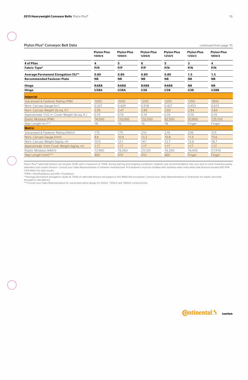
Plylon Plus® Conveyor Belt Data continued from page 15
Plylon Plus 1000/4
Plylon Plus 1000/5
Plylon Plus 1200/6
Plylon Plus 1250/5
Plylon Plus 1350/3
Plylon Plus 1800/4
# of Plies 4 5 6 5 3 4
Fabric Type* P/N P/P P/P P/N P/N P/N
Average Permanent Elongation (%)** 0.80 0.80 0.80 0.80 1.5 1.5
Recommended Fastener Plate NR NR NR NR NR NR
Hinge RAR8 RAR8 RAR8 RAR8 NR NR
Hinge U38A U38A U38 U38 U38 U38B
Imperial
Vulcanized & Fastener Rating (PIW) 1000 1000 1200 1250 1350 1800
Nom. Carcass Gauge (in.) 0.337 0.429 0.518 0.427 0.453 0.613
Nom. Carcass Weight (lb./sq. ft.) 2.05 2.47 2.89 2.60 2.84 3.84
Approximate 1/32 in. Cover Weight (lb./sq. ft.) 0.19 0.19 0.19 0.19 0.19 0.19
Elastic Modulus (PIW) 74,000 110,000 132,000 92,500 93,800 125,100
Step Length (in.)*** 18 16 16 18 Finger Finger
Metric
Vulcanized & Fastener Rating (kN/m) 175 175 210 219 236 315
Nom. Carcass Gauge (mm) 8.6 10.9 13.2 10.8 11.5 15.6
Nom. Carcass Weight (kg/sq. m) 10.0 12.1 14.1 12.7 13.9 18.7
Approximate 1mm Cover Weight (kg/sq. m) 1.17 1.17 1.17 1.17 1.17 1.17
Elastic Modulus (kN/m) 12,960 19,260 23,120 16,200 16,430 21,910
Step Length (mm)*** 460 410 410 460 Finger Finger
Plylon Plus® rated belt tension can exceed 100%, with a maximum of 150%, during starting and stopping conditions. Fastener size recommendation may vary due to cover thickness,pulley diameters and system tension. Consult your Sales Representative or fastener manufacturer. R-6 fasteners must be installed with stainless steel rivets when belt tensions exceed 800 PIW (140 kN/m) for best results. *P/PN = Poly/PolyNylon and P/N = Poly/Nylon **Average permanent elongation values at 100% of rated belt tension are based on ISO 9856 test procedure. Consult your Sales Representative or Distributor for elastic and total elongation calculations. ***Consult your Sales Representative for vulcanized splice design for 900/2, 1350/3 and 1800/4 constructions.
16 2015 Heavyweight Conveyor Belts Plylon Plus®
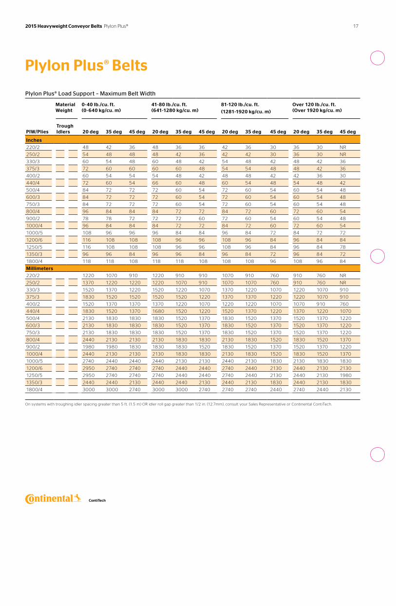
Plylon Plus® Load Support – Maximum Belt Width
Material Weight
0-40 lb./cu. ft. (0-640 kg/cu. m)
41-80 lb./cu. ft. (641-1280 kg/cu. m)
81-120 lb./cu. ft.
(1281-1920 kg/cu. m)
Over 120 lb./cu. ft. (Over 1920 kg/cu. m)
PIW/Plies
Trough Idlers
20 deg
35 deg
45 deg
20 deg
35 deg
45 deg
20 deg
35 deg
45 deg
20 deg
35 deg
45 deg
Inches
220/2 48 42 36 48 36 36 42 36 30 36 30 NR
250/2 54 48 48 48 42 36 42 42 30 36 30 NR
330/3 60 54 48 60 48 42 54 48 42 48 42 36
375/3 72 60 60 60 60 48 54 54 48 48 42 36
400/2 60 54 54 54 48 42 48 48 42 42 36 30
440/4 72 60 54 66 60 48 60 54 48 54 48 42
500/4 84 72 72 72 60 54 72 60 54 60 54 48
600/3 84 72 72 72 60 54 72 60 54 60 54 48
750/3 84 72 72 72 60 54 72 60 54 60 54 48
800/4 96 84 84 84 72 72 84 72 60 72 60 54
900/2 78 78 72 72 72 60 72 60 54 60 54 48
1000/4 96 84 84 84 72 72 84 72 60 72 60 54
1000/5 108 96 96 96 84 84 96 84 72 84 72 72
1200/6 116 108 108 108 96 96 108 96 84 96 84 84
1250/5 116 108 108 108 96 96 108 96 84 96 84 78
1350/3 96 96 84 96 96 84 96 84 72 96 84 72
1800/4 118 118 108 118 118 108 108 108 96 108 96 84
Millimeters
220/2 1220 1070 910 1220 910 910 1070 910 760 910 760 NR
250/2 1370 1220 1220 1220 1070 910 1070 1070 760 910 760 NR
330/3 1520 1370 1220 1520 1220 1070 1370 1220 1070 1220 1070 910
375/3 1830 1520 1520 1520 1520 1220 1370 1370 1220 1220 1070 910
400/2 1520 1370 1370 1370 1220 1070 1220 1220 1070 1070 910 760
440/4 1830 1520 1370 1680 1520 1220 1520 1370 1220 1370 1220 1070
500/4 2130 1830 1830 1830 1520 1370 1830 1520 1370 1520 1370 1220
600/3 2130 1830 1830 1830 1520 1370 1830 1520 1370 1520 1370 1220
750/3 2130 1830 1830 1830 1520 1370 1830 1520 1370 1520 1370 1220
800/4 2440 2130 2130 2130 1830 1830 2130 1830 1520 1830 1520 1370
900/2 1980 1980 1830 1830 1830 1520 1830 1520 1370 1520 1370 1220
1000/4 2440 2130 2130 2130 1830 1830 2130 1830 1520 1830 1520 1370
1000/5 2740 2440 2440 2440 2130 2130 2440 2130 1830 2130 1830 1830
1200/6 2950 2740 2740 2740 2440 2440 2740 2440 2130 2440 2130 2130
1250/5 2950 2740 2740 2740 2440 2440 2740 2440 2130 2440 2130 1980
1350/3 2440 2440 2130 2440 2440 2130 2440 2130 1830 2440 2130 1830
1800/4 3000 3000 2740 3000 3000 2740 2740 2740 2440 2740 2440 2130
On systems with troughing idler spacing greater than 5 ft. (1.5 m) OR idler roll gap greater than 1/2 in. (12.7mm), consult your Sales Representative or Continental ContiTech.
Plylon Plus® Belts
17 2015 Heavyweight Conveyor Belts Plylon Plus®
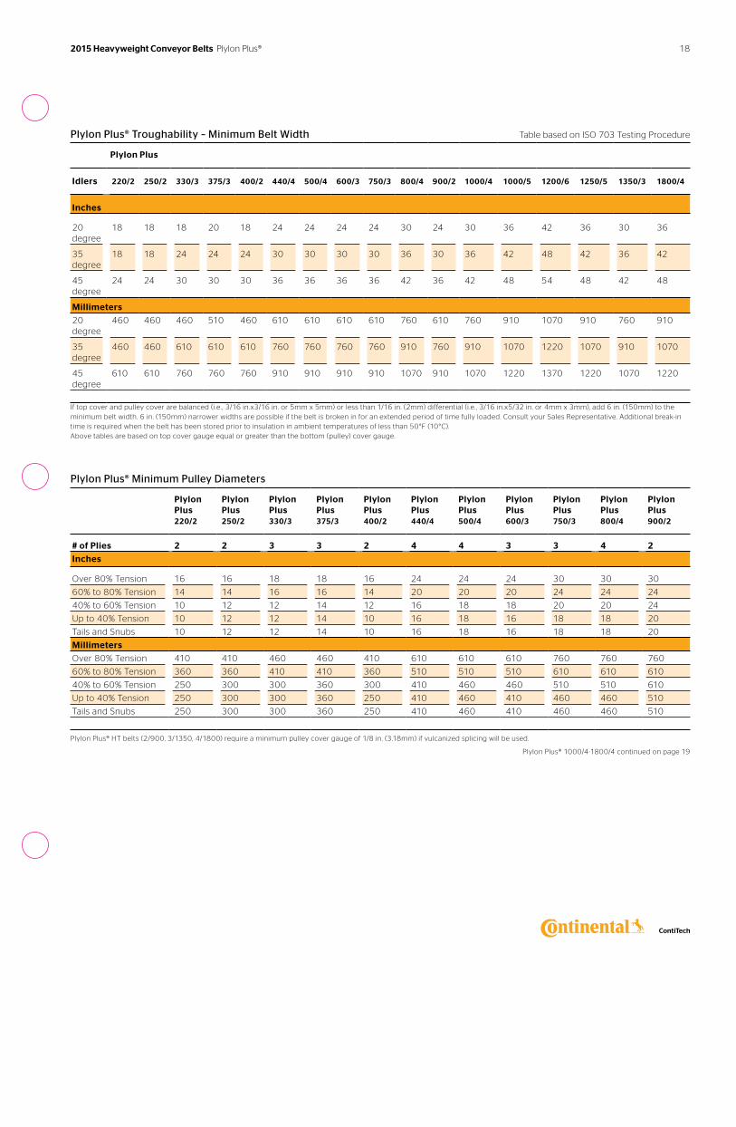
Plylon Plus® Troughability – Minimum Belt Width Table based on ISO 703 Testing Procedure
Plylon Plus
Idlers 220/2 250/2 330/3 375/3 400/2 440/4 500/4 600/3 750/3 800/4 900/2 1000/4 1000/5 1200/6 1250/5 1350/3 1800/4
Inches
20 degree
18 18 18 20 18 24 24 24 24 30 24 30 36 42 36 30 36
35 degree
18 18 24 24 24 30 30 30 30 36 30 36 42 48 42 36 42
45 degree
24 24 30 30 30 36 36 36 36 42 36 42 48 54 48 42 48
Millimeters
20 degree
460 460 460 510 460 610 610 610 610 760 610 760 910 1070 910 760 910
35 degree
460 460 610 610 610 760 760 760 760 910 760 910 1070 1220 1070 910 1070
45 degree
610 610 760 760 760 910 910 910 910 1070 910 1070 1220 1370 1220 1070 1220
If top cover and pulley cover are balanced (i.e. , 3/16 in.x3/16 in. or 5mm x 5mm) or less than 1/16 in. (2mm) differential (i.e. , 3/16 in.x5/32 in. or 4mm x 3mm), add 6 in. (150mm) to the minimum belt width. 6 in. (150mm) narrower widths are possible if the belt is broken in for an extended period of time fully loaded. Consult your Sales Representative. Additional break-in time is required when the belt has been stored prior to insulation in ambient temperatures of less than 50°F (10°C). Above tables are based on top cover gauge equal or greater than the bottom (pulley) cover gauge.
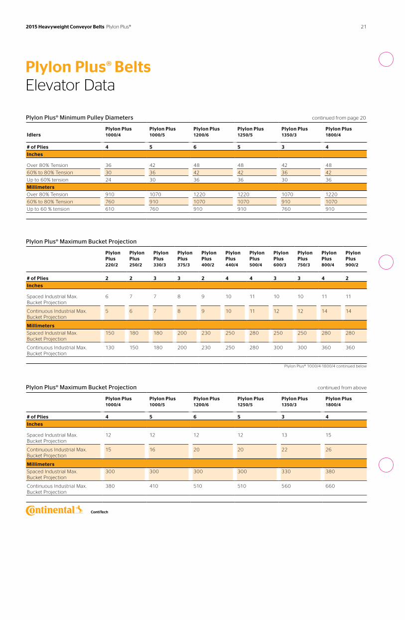
Plylon Plus® Minimum Pulley Diameters
Plylon Plus 220/2
Plylon Plus 250/2
Plylon Plus 330/3
Plylon Plus 375/3
Plylon Plus 400/2
Plylon Plus 440/4
Plylon Plus 500/4
Plylon Plus 600/3
Plylon Plus 750/3
Plylon Plus 800/4
Plylon Plus 900/2
# of Plies 2 2 3 3 2 4 4 3 3 4 2
Inches
Over 80% Tension 16 16 18 18 16 24 24 24 30 30 30
60% to 80% Tension 14 14 16 16 14 20 20 20 24 24 24
40% to 60% Tension 10 12 12 14 12 16 18 18 20 20 24
Up to 40% Tension 10 12 12 14 10 16 18 16 18 18 20
Tails and Snubs 10 12 12 14 10 16 18 16 18 18 20
Millimeters
Over 80% Tension 410 410 460 460 410 610 610 610 760 760 760
60% to 80% Tension 360 360 410 410 360 510 510 510 610 610 610
40% to 60% Tension 250 300 300 360 300 410 460 460 510 510 610
Up to 40% Tension 250 300 300 360 250 410 460 410 460 460 510
Tails and Snubs 250 300 300 360 250 410 460 410 460 460 510
Plylon Plus® HT belts (2/900, 3/1350, 4/1800) require a minimum pulley cover gauge of 1/8 in. (3.18mm) if vulcanized splicing will be used.
Plylon Plus® 1000/4-1800/4 continued on page 19
2015 Heavyweight Conveyor Belts Plylon Plus® 18
Elevator Data
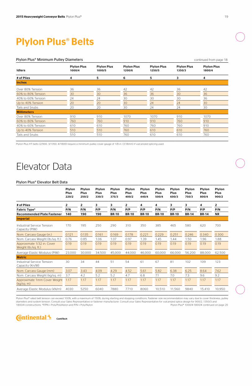
Plylon Plus® Elevator Belt Data
Plylon Plus 220/2
Plylon Plus 250/2
Plylon Plus 330/3
Plylon Plus 375/3
Plylon Plus 400/2
Plylon Plus 440/4
Plylon Plus 500/4
Plylon Plus 600/3
Plylon Plus 750/3
Plylon Plus 800/4
Plylon Plus 900/2
# of Plies 2 2 3 3 2 4 4 3 3 4 2
Fabric Type* P/N P/N P/P P/N P/P P/P P/N P/P P/N P/P P/N
Recommended Plate Fastener 140 190 190 BR-10 BR-10 BR-10 BR-10 BR-10 BR-14 BR-14 NR
Imperial
Industrial Service Tension Capacity (PIW)
170 195 250 290 310 350 385 465 580 620 700
Nom. Carcass Gauge (in.) 0.121 0.135 0.161 0.169 0.178 0.221 0.229 0.251 0.246 0.340 0.300
Nom. Carcass Weight (lb./sq. ft.) 0.76 0.85 1.06 1.07 0.97 1.39 1.45 1.44 1.50 1.96 1.88
Approximate 1/32 in. Cover Weight (lb./sq. ft.)
0.19 0.19 0.19 0.19 0.19 0.19 0.19 0.19 0.19 0.19 0.19
Average Elastic Modulus (PIW) 23,000 30,000 34,500 45,000 44,000 46,000 60,000 66,000 56,200 88,000 62,500
Metric
Industrial Service Tension Capacity (Kn/M)
30 34 44 51 54 61 67 81 102 109 123
Nom. Carcass Gauge (mm) 3.07 3.43 4.09 4.29 4.52 5.61 5.82 6.38 6.25 8.64 7.62
Nom. Carcass Weight (kg/sq. m) 3.7 4.2 5.2 5.2 4.7 6.8 7.1 7.0 7.3 9.6 9.2
Approximate 1mm Cover Weight (kg/sq. m)
1.17 1.17 1.17 1.17 1.17 1.17 1.17 1.17 1.17 1.17 1.17
Average Elastic Modulus (kN/m) 4030 5250 6040 7880 7710 8060 10,510 11,560 9840 15,410 10,950
Plylon Plus® rated belt tension can exceed 100%, with a maximum of 150%, during starting and stopping conditions. Fastener size recommendation may vary due to cover thickness, pulley diameters and system tension. Consult your Sales Representative or fastener manufacturer. Consult your Sales Representative for vulcanized splice design for 900/2, 1350/3 and 1800/4 constructions. *P/PN = Poly/PolyNylon and P/N = Poly/Nylon Plylon Plus® 1000/4-1800/4 continued on page 20
Plylon Plus® Belts
Plylon Plus® Minimum Pulley Diameters continued from page 18
Idlers
Plylon Plus 1000/4
Plylon Plus 1000/5
Plylon Plus 1200/6
Plylon Plus 1250/5
Plylon Plus 1350/3
Plylon Plus 1800/4
# of Plies 4 5 6 5 3 4
Inches
Over 80% Tension 36 36 42 42 36 42
60% to 80% Tension 30 30 36 36 30 36
40% to 60% Tension 24 24 30 30 30 36
Up to 40% Tension 20 20 30 24 24 30
Tails and Snubs 20 20 30 24 24 30
Millimeters
Over 80% Tension 910 910 1070 1070 910 1070
60% to 80% Tension 760 760 910 910 760 910
40% to 60% Tension 610 610 760 760 760 910
Up to 40% Tension 510 510 760 610 610 760
Tails and Snubs 510 510 760 610 610 760
Plylon Plus HT belts (2/900, 3/1350, 4/1800) require a minimum pulley cover gauge of 1/8 in. (3.18mm) if vulcanized splicing used.
19 2015 Heavyweight Conveyor Belts Plylon Plus®
Plylon Plus® Minimum Pulley Diameters
Idlers
Plylon Plus 220/2
Plylon Plus 250/2
Plylon Plus 330/3
Plylon Plus 375/3
Plylon Plus 400/2
Plylon Plus 440/4
Plylon Plus 500/4
Plylon Plus 600/3
Plylon Plus 750/3
Plylon Plus 800/4
Plylon Plus 900/2
# of Plies 2 2 3 3 2 4 4 3 3 4 2
Inches
Over 80% Tension 16 16 18 18 18 24 24 30 30 36 36
60% to 80% Tension 14 14 16 16 16 22 22 24 24 30 30
Up to 60% tension 12 12 14 14 14 20 20 20 20 24 24
Millimeters
Over 80% Tension 410 410 460 460 460 610 610 760 760 910 910
60% to 80% Tension 360 360 410 410 410 560 560 610 610 760 760
Up to 60 % tension 300 300 360 360 360 510 510 510 510 610 610
Plylon Plus® 1000/4-1800/4 continued on page 20
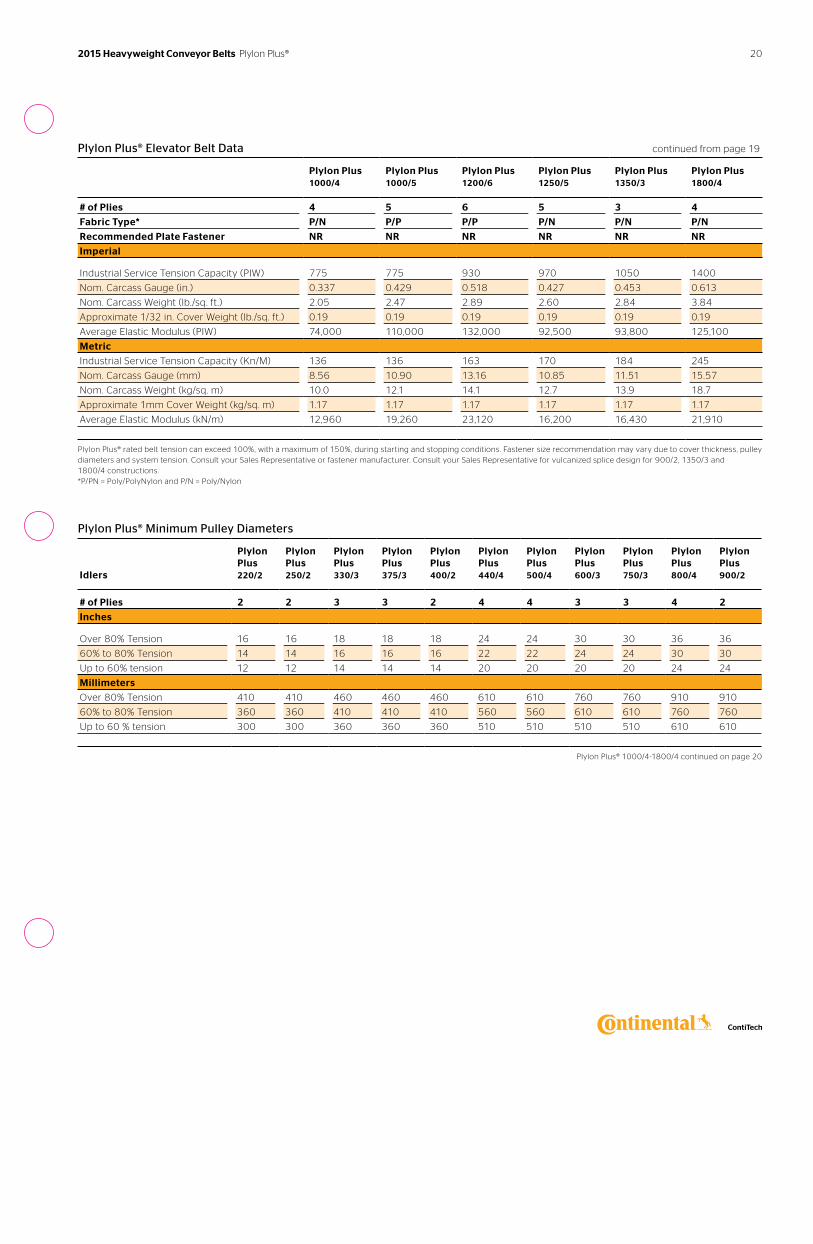
Plylon Plus® Elevator Belt Data continued from page 19
Plylon Plus 1000/4
Plylon Plus 1000/5
Plylon Plus 1200/6
Plylon Plus 1250/5
Plylon Plus 1350/3
Plylon Plus 1800/4
# of Plies 4 5 6 5 3 4
Fabric Type* P/N P/P P/P P/N P/N P/N
Recommended Plate Fastener NR NR NR NR NR NR
Imperial
Industrial Service Tension Capacity (PIW) 775 775 930 970 1050 1400
Nom. Carcass Gauge (in.) 0.337 0.429 0.518 0.427 0.453 0.613
Nom. Carcass Weight (lb./sq. ft.) 2.05 2.47 2.89 2.60 2.84 3.84
Approximate 1/32 in. Cover Weight (lb./sq. ft.) 0.19 0.19 0.19 0.19 0.19 0.19
Average Elastic Modulus (PIW) 74,000 110,000 132,000 92,500 93,800 125,100
Metric
Industrial Service Tension Capacity (Kn/M) 136 136 163 170 184 245
Nom. Carcass Gauge (mm) 8.56 10.90 13.16 10.85 11.51 15.57
Nom. Carcass Weight (kg/sq. m) 10.0 12.1 14.1 12.7 13.9 18.7
Approximate 1mm Cover Weight (kg/sq. m) 1.17 1.17 1.17 1.17 1.17 1.17
Average Elastic Modulus (kN/m) 12,960 19,260 23,120 16,200 16,430 21,910
Plylon Plus® rated belt tension can exceed 100%, with a maximum of 150%, during starting and stopping conditions. Fastener size recommendation may vary due to cover thickness, pulley diameters and system tension. Consult your Sales Representative or fastener manufacturer. Consult your Sales Representative for vulcanized splice design for 900/2, 1350/3 and 1800/4 constructions. *P/PN = Poly/PolyNylon and P/N = Poly/Nylon
20 2015 Heavyweight Conveyor Belts Plylon Plus®
Plylon Plus® Belts Elevator Data
Plylon Plus® Minimum Pulley Diameters continued from page 20
Idlers
Plylon Plus 1000/4
Plylon Plus 1000/5
Plylon Plus 1200/6
Plylon Plus 1250/5
Plylon Plus 1350/3
Plylon Plus 1800/4
# of Plies 4 5 6 5 3 4
Inches
Over 80% Tension 36 42 48 48 42 48
60% to 80% Tension 30 36 42 42 36 42
Up to 60% tension 24 30 36 36 30 36
Millimeters
Over 80% Tension 910 1070 1220 1220 1070 1220
60% to 80% Tension 760 910 1070 1070 910 1070
Up to 60 % tension 610 760 910 910 760 910
Plylon Plus® Maximum Bucket Projection
Plylon Plus 220/2
Plylon Plus 250/2
Plylon Plus 330/3
Plylon Plus 375/3
Plylon Plus 400/2
Plylon Plus 440/4
Plylon Plus 500/4
Plylon Plus 600/3
Plylon Plus 750/3
Plylon Plus 800/4
Plylon Plus 900/2
# of Plies 2 2 3 3 2 4 4 3 3 4 2
Inches
Spaced Industrial Max. Bucket Projection
6 7 7 8 9 10 11 10 10 11 11
Continuous Industrial Max. Bucket Projection
5 6 7 8 9 10 11 12 12 14 14
Millimeters
Spaced Industrial Max. Bucket Projection
150 180 180 200 230 250 280 250 250 280 280
Continuous Industrial Max. Bucket Projection
130 150 180 200 230 250 280 300 300 360 360
Plylon Plus® 1000/4-1800/4 continued below
Plylon Plus® Maximum Bucket Projection continued from above
Plylon Plus 1000/4
Plylon Plus 1000/5
Plylon Plus 1200/6
Plylon Plus 1250/5
Plylon Plus 1350/3
Plylon Plus 1800/4
# of Plies 4 5 6 5 3 4
Inches
Spaced Industrial Max. Bucket Projection
12 12 12 12 13 15
Continuous Industrial Max. Bucket Projection
15 16 20 20 22 26
Millimeters
Spaced Industrial Max. Bucket Projection
300 300 300 300 330 380
Continuous Industrial Max. Bucket Projection
380 410 510 510 560 660
21 2015 Heavyweight Conveyor Belts Plylon Plus®
Markets Applications Cover Compounds
› Aggregate› Package Handling› Sand and Gravel
› 3 inch Minus Rock› Load Out› Low Abuse› Radial Stacker› Ready Mix› Stacker
› General Trade› MOR
See pages 72-77 for more specific details.
See the process diagram for Aggregate, Hard Rock Mining, Sand and Gravel markets on page 6 for alternative belt recommendations.
Get a lower cost-per-ton conveyed. Tension Range: 220 to 600 PIW
Spartan® Belts
Continental ContiTech Spartan® is an economical fabric belt construction. Spartan® belts are recommended for material less than 3 inches in diameter.
22 2015 Heavyweight Conveyor Belts Spartan®
Spartan® Belts
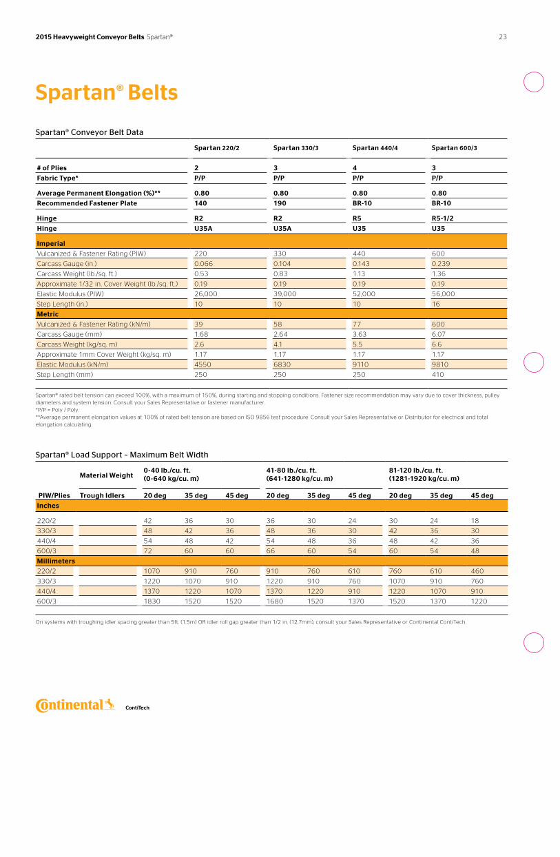
Spartan® Conveyor Belt Data
Spartan 220/2 Spartan 330/3 Spartan 440/4 Spartan 600/3
# of Plies 2 3 4 3
Fabric Type* P/P P/P P/P P/P
Average Permanent Elongation (%)** 0.80 0.80 0.80 0.80
Recommended Fastener Plate 140 190 BR-10 BR-10
Hinge R2 R2 R5 R5-1/2
Hinge U35A U35A U35 U35
Imperial
Vulcanized & Fastener Rating (PIW) 220 330 440 600
Carcass Gauge (in.) 0.066 0.104 0.143 0.239
Carcass Weight (lb./sq. ft.) 0.53 0.83 1.13 1.36
Approximate 1/32 in. Cover Weight (lb./sq. ft.) 0.19 0.19 0.19 0.19
Elastic Modulus (PIW) 26,000 39,000 52,000 56,000
Step Length (in.) 10 10 10 16
Metric
Vulcanized & Fastener Rating (kN/m) 39 58 77 600
Carcass Gauge (mm) 1.68 2.64 3.63 6.07
Carcass Weight (kg/sq. m) 2.6 4.1 5.5 6.6
Approximate 1mm Cover Weight (kg/sq. m) 1.17 1.17 1.17 1.17
Elastic Modulus (kN/m) 4550 6830 9110 9810
Step Length (mm) 250 250 250 410
Spartan® rated belt tension can exceed 100%, with a maximum of 150%, during starting and stopping conditions. Fastener size recommendation may vary due to cover thickness, pulley diameters and system tension. Consult your Sales Representative or fastener manufacturer. *P/P = Poly / Poly. **Average permanent elongation values at 100% of rated belt tension are based on ISO 9856 test procedure. Consult your Sales Representative or Distributor for electrical and total elongation calculating.
Spartan® Load Support – Maximum Belt Width
Material Weight0-40 lb./cu. ft. (0-640 kg/cu. m)
41-80 lb./cu. ft. (641-1280 kg/cu. m)
81-120 lb./cu. ft. (1281-1920 kg/cu. m)
PIW/Plies Trough Idlers 20 deg 35 deg 45 deg 20 deg 35 deg 45 deg 20 deg 35 deg 45 deg
Inches
220/2 42 36 30 36 30 24 30 24 18
330/3 48 42 36 48 36 30 42 36 30
440/4 54 48 42 54 48 36 48 42 36
600/3 72 60 60 66 60 54 60 54 48
Millimeters
220/2 1070 910 760 910 760 610 760 610 460
330/3 1220 1070 910 1220 910 760 1070 910 760
440/4 1370 1220 1070 1370 1220 910 1220 1070 910
600/3 1830 1520 1520 1680 1520 1370 1520 1370 1220
On systems with troughing idler spacing greater than 5ft. (1.5m) OR idler roll gap greater than 1/2 in. (12.7mm), consult your Sales Representative or Continental ContiTech.
23 2015 Heavyweight Conveyor Belts Spartan®
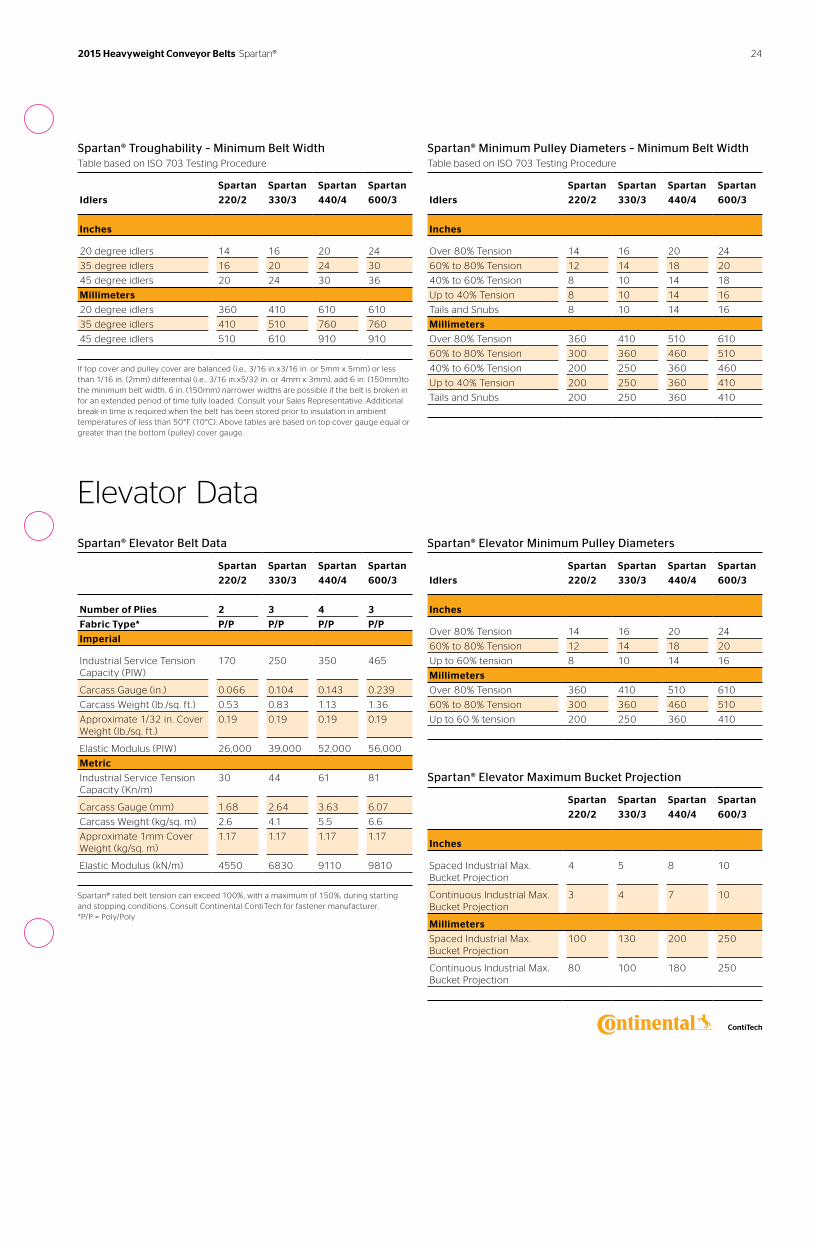
Spartan® Troughability – Minimum Belt WidthTable based on ISO 703 Testing Procedure
Idlers
Spartan
220/2
Spartan
330/3
Spartan
440/4
Spartan
600/3
Inches
20 degree idlers 14 16 20 24
35 degree idlers 16 20 24 30
45 degree idlers 20 24 30 36
Millimeters
20 degree idlers 360 410 610 610
35 degree idlers 410 510 760 760
45 degree idlers 510 610 910 910
If top cover and pulley cover are balanced (i.e. , 3/16 in.x3/16 in. or 5mm x 5mm) or less than 1/16 in. (2mm) differential (i.e. , 3/16 in.x5/32 in. or 4mm x 3mm), add 6 in. (150mm)to the minimum belt width. 6 in. (150mm) narrower widths are possible if the belt is broken in for an extended period of time fully loaded. Consult your Sales Representative. Additional break-in time is required when the belt has been stored prior to insulation in ambient temperatures of less than 50°F (10°C). Above tables are based on top cover gauge equal or greater than the bottom (pulley) cover gauge.
Spartan® Minimum Pulley Diameters – Minimum Belt WidthTable based on ISO 703 Testing Procedure
Idlers
Spartan
220/2
Spartan
330/3
Spartan
440/4
Spartan
600/3
Inches
Over 80% Tension 14 16 20 24
60% to 80% Tension 12 14 18 20
40% to 60% Tension 8 10 14 18
Up to 40% Tension 8 10 14 16
Tails and Snubs 8 10 14 16
Millimeters
Over 80% Tension 360 410 510 610
60% to 80% Tension 300 360 460 510
40% to 60% Tension 200 250 360 460
Up to 40% Tension 200 250 360 410
Tails and Snubs 200 250 360 410
Elevator Data
Spartan® Elevator Belt Data
Spartan
220/2
Spartan
330/3
Spartan
440/4
Spartan
600/3
Number of Plies 2 3 4 3
Fabric Type* P/P P/P P/P P/P
Imperial
Industrial Service Tension Capacity (PIW)
170 250 350 465
Carcass Gauge (in.) 0.066 0.104 0.143 0.239
Carcass Weight (lb./sq. ft.) 0.53 0.83 1.13 1.36
Approximate 1/32 in. Cover Weight (lb./sq. ft.)
0.19 0.19 0.19 0.19
Elastic Modulus (PIW) 26,000 39,000 52,000 56,000
Metric
Industrial Service Tension Capacity (Kn/m)
30 44 61 81
Carcass Gauge (mm) 1.68 2.64 3.63 6.07
Carcass Weight (kg/sq. m) 2.6 4.1 5.5 6.6
Approximate 1mm Cover Weight (kg/sq. m)
1.17 1.17 1.17 1.17
Elastic Modulus (kN/m) 4550 6830 9110 9810
Spartan® rated belt tension can exceed 100%, with a maximum of 150%, during starting and stopping conditions. Consult Continental ContiTech for fastener manufacturer. *P/P = Poly/Poly
Spartan® Elevator Minimum Pulley Diameters
Idlers
Spartan
220/2
Spartan
330/3
Spartan
440/4
Spartan
600/3
Inches
Over 80% Tension 14 16 20 24
60% to 80% Tension 12 14 18 20
Up to 60% tension 8 10 14 16
Millimeters
Over 80% Tension 360 410 510 610
60% to 80% Tension 300 360 460 510
Up to 60 % tension 200 250 360 410
Spartan® Elevator Maximum Bucket Projection
Spartan
220/2
Spartan
330/3
Spartan
440/4
Spartan
600/3
Inches
Spaced Industrial Max. Bucket Projection
4 5 8 10
Continuous Industrial Max. Bucket Projection
3 4 7 10
Millimeters
Spaced Industrial Max. Bucket Projection
100 130 200 250
Continuous Industrial Max. Bucket Projection
80 100 180 250
24 2015 Heavyweight Conveyor Belts Spartan®
Markets Applications Cover Compounds
› Cement› Foundry› Iron Ore› Steel Production› Taconite
› Cement Clinker› Coke Plants› Hot Powdery Materials› Sintered Ore› Steel Mills› Taconite Pellets
› Solar-Shield® XL 750
See pages 72-77 for more specific details.
Get a lower cost-per-ton conveyed. Tension Range: 220 to 1200 PIW
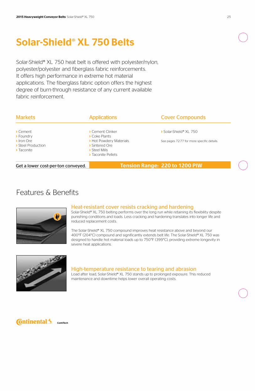
Solar-Shield® XL 750 Belts
Solar-Shield® XL 750 heat belt is offered with polyester/nylon, polyester/polyester and fiberglass fabric reinforcements. It offers high performance in extreme hot material applications. The fiberglass fabric option offers the highest degree of burn-through resistance of any current available fabric reinforcement.
Features & Benefits
Heat-resistant cover resists cracking and hardeningSolar-Shield® XL 750 belting performs over the long run while retaining its flexibility despite punishing conditions and loads. Less cracking and hardening translates into longer life and reduced replacement costs.
The Solar-Shield® XL 750 compound improves heat resistance above and beyond our 400°F (204°C) compound and significantly extends belt life. The Solar-Shield® XL 750 was designed to handle hot material loads up to 750°F (399°C), providing extreme longevity in severe heat applications.
High-temperature resistance to tearing and abrasionLoad after load, Solar-Shield® XL 750 stands up to prolonged exposure. This reduced maintenance and downtime helps lower overall operating costs.
25 2015 Heavyweight Conveyor Belts Solar-Shield® XL 750
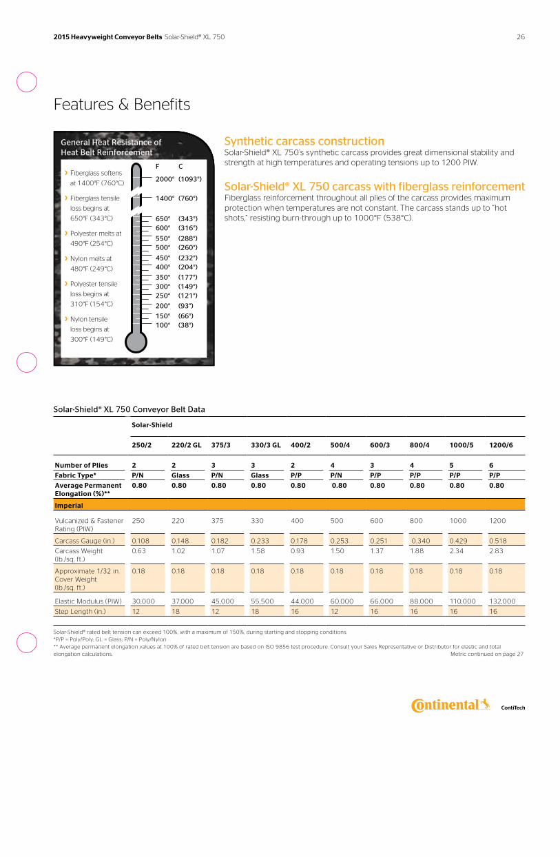
Features & Benefits
General Heat Resistance of Heat Belt Reinforcement
› Fiberglass softens
at 1400°F (760°C)
› Fiberglass tensile
loss begins at
650°F (343°C)
› Polyester melts at
490°F (254°C)
› Nylon melts at
480°F (249°C)
› Polyester tensile
loss begins at
310°F (154°C)
› Nylon tensile
loss begins at
300°F (149°C)
F C
2000° (1093°)
1400° (760°)
650° (343°)600° (316°)
500° (260°)
450° (232°)400° (204°)
550° (288°)
350° (177°)300° (149°)250° (121°)
200° (93°)
150° (66°)100° (38°)
Synthetic carcass constructionSolar-Shield® XL 750’s synthetic carcass provides great dimensional stability and strength at high temperatures and operating tensions up to 1200 PIW.
Solar-Shield® XL 750 carcass with fiberglass reinforcementFiberglass reinforcement throughout all plies of the carcass provides maximum protection when temperatures are not constant. The carcass stands up to “hot shots,” resisting burn-through up to 1000°F (538°C).
Solar-Shield® XL 750 Conveyor Belt Data
Solar-Shield
250/2 220/2 GL 375/3 330/3 GL 400/2 500/4 600/3 800/4 1000/5 1200/6
Number of Plies 2 2 3 3 2 4 3 4 5 6
Fabric Type* P/N Glass P/N Glass P/P P/N P/P P/P P/P P/P
Average Permanent Elongation (%)**
0.80 0.80 0.80 0.80 0.80 0.80 0.80 0.80 0.80 0.80
Imperial
Vulcanized & Fastener Rating (PIW)
250 220 375 330 400 500 600 800 1000 1200
Carcass Gauge (in.) 0.108 0.148 0.182 0.233 0.178 0.253 0.251 0.340 0.429 0.518
Carcass Weight (lb./sq. ft.)
0.63 1.02 1.07 1.58 0.93 1.50 1.37 1.88 2.34 2.83
Approximate 1/32 in. Cover Weight (lb./sq. ft.)
0.18 0.18 0.18 0.18 0.18 0.18 0.18 0.18 0.18 0.18
Elastic Modulus (PIW) 30,000 37,000 45,000 55,500 44,000 60,000 66,000 88,000 110,000 132,000
Step Length (in.) 12 18 12 18 16 12 16 16 16 16
Solar-Shield® rated belt tension can exceed 100%, with a maximum of 150%, during starting and stopping conditions. *P/P = Poly/Poly; GL = Glass; P/N = Poly/Nylon ** Average permanent elongation values at 100% of rated belt tension are based on ISO 9856 test procedure. Consult your Sales Representative or Distributor for elastic and total elongation calculations. Metric continued on page 27
26 2015 Heavyweight Conveyor Belts Solar-Shield® XL 750
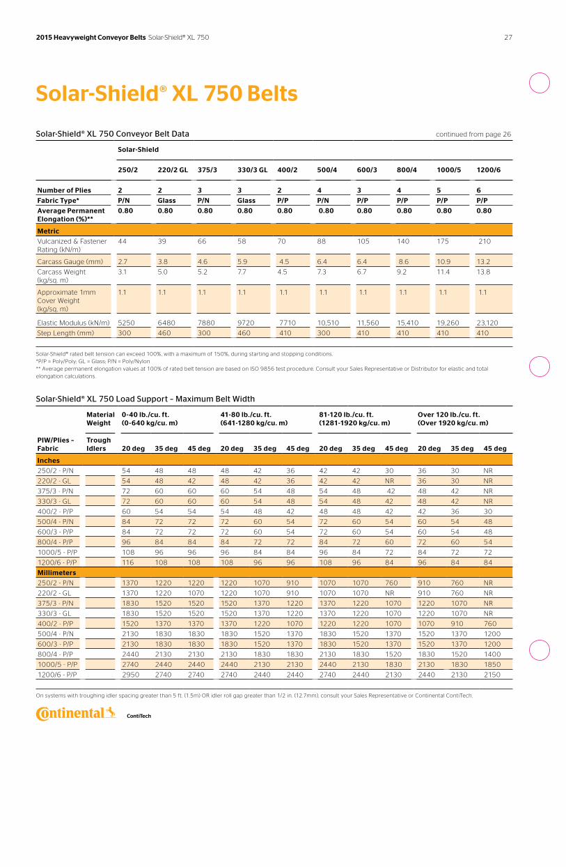
Solar-Shield® XL 750 Belts
Solar-Shield® XL 750 Conveyor Belt Data continued from page 26
Solar-Shield
250/2 220/2 GL 375/3 330/3 GL 400/2 500/4 600/3 800/4 1000/5 1200/6
Number of Plies 2 2 3 3 2 4 3 4 5 6
Fabric Type* P/N Glass P/N Glass P/P P/N P/P P/P P/P P/P
Average Permanent Elongation (%)**
0.80 0.80 0.80 0.80 0.80 0.80 0.80 0.80 0.80 0.80
Metric
Vulcanized & Fastener Rating (kN/m)
44 39 66 58 70 88 105 140 175 210
Carcass Gauge (mm) 2.7 3.8 4.6 5.9 4.5 6.4 6.4 8.6 10.9 13.2
Carcass Weight (kg/sq. m)
3.1 5.0 5.2 7.7 4.5 7.3 6.7 9.2 11.4 13.8
Approximate 1mm Cover Weight (kg/sq. m)
1.1 1.1 1.1 1.1 1.1 1.1 1.1 1.1 1.1 1.1
Elastic Modulus (kN/m) 5250 6480 7880 9720 7710 10,510 11,560 15,410 19,260 23,120
Step Length (mm) 300 460 300 460 410 300 410 410 410 410
Solar-Shield® rated belt tension can exceed 100%, with a maximum of 150%, during starting and stopping conditions. *P/P = Poly/Poly; GL = Glass; P/N = Poly/Nylon ** Average permanent elongation values at 100% of rated belt tension are based on ISO 9856 test procedure. Consult your Sales Representative or Distributor for elastic and total elongation calculations.
Solar-Shield® XL 750 Load Support – Maximum Belt Width
Material Weight
0-40 lb./cu. ft. (0-640 kg/cu. m)
41-80 lb./cu. ft. (641-1280 kg/cu. m)
81-120 lb./cu. ft. (1281-1920 kg/cu. m)
Over 120 lb./cu. ft. (Over 1920 kg/cu. m)
PIW/Plies – Fabric
Trough Idlers
20 deg
35 deg
45 deg
20 deg
35 deg
45 deg
20 deg
35 deg
45 deg
20 deg
35 deg
45 deg
Inches
250/2 - P/N 54 48 48 48 42 36 42 42 30 36 30 NR
220/2 - GL 54 48 42 48 42 36 42 42 NR 36 30 NR
375/3 - P/N 72 60 60 60 54 48 54 48 42 48 42 NR
330/3 - GL 72 60 60 60 54 48 54 48 42 48 42 NR
400/2 - P/P 60 54 54 54 48 42 48 48 42 42 36 30
500/4 - P/N 84 72 72 72 60 54 72 60 54 60 54 48
600/3 - P/P 84 72 72 72 60 54 72 60 54 60 54 48
800/4 - P/P 96 84 84 84 72 72 84 72 60 72 60 54
1000/5 - P/P 108 96 96 96 84 84 96 84 72 84 72 72
1200/6 - P/P 116 108 108 108 96 96 108 96 84 96 84 84
Millimeters
250/2 - P/N 1370 1220 1220 1220 1070 910 1070 1070 760 910 760 NR
220/2 - GL 1370 1220 1070 1220 1070 910 1070 1070 NR 910 760 NR
375/3 - P/N 1830 1520 1520 1520 1370 1220 1370 1220 1070 1220 1070 NR
330/3 - GL 1830 1520 1520 1520 1370 1220 1370 1220 1070 1220 1070 NR
400/2 - P/P 1520 1370 1370 1370 1220 1070 1220 1220 1070 1070 910 760
500/4 - P/N 2130 1830 1830 1830 1520 1370 1830 1520 1370 1520 1370 1200
600/3 - P/P 2130 1830 1830 1830 1520 1370 1830 1520 1370 1520 1370 1200
800/4 - P/P 2440 2130 2130 2130 1830 1830 2130 1830 1520 1830 1520 1400
1000/5 - P/P 2740 2440 2440 2440 2130 2130 2440 2130 1830 2130 1830 1850
1200/6 - P/P 2950 2740 2740 2740 2440 2440 2740 2440 2130 2440 2130 2150
On systems with troughing idler spacing greater than 5 ft. (1.5m) OR idler roll gap greater than 1/2 in. (12.7mm), consult your Sales Representative or Continental ContiTech.
27 2015 Heavyweight Conveyor Belts Solar-Shield® XL 750
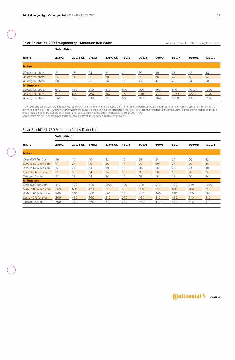
Solar-Shield® XL 750 Troughability – Minimum Belt Width Table based on ISO 703 Testing Procedure
Solar-Shield
Idlers 250/2 220/2 GL 375/3 330/3 GL 400/2 500/4 600/3 800/4 1000/5 1200/6
Inches
20 degree idlers 24 18 24 24 24 30 30 36 42 48
35 degree idlers 24 24 30 30 30 36 36 42 48 54
45 degree idlers 30 30 36 36 36 42 42 48 54 60
Millimeters
20 degree idlers 610 460 610 610 610 760 760 910 1070 1220
35 degree idlers 610 610 760 760 760 910 910 1070 1220 1370
45 degree idlers 760 760 910 910 910 1070 1070 1220 1370 1520
If top cover and pulley cover are balanced (i.e. , 3/16 in.x3/16 in. or 5mm x 5mm) or less than 1/16 in. (2mm) differential (i.e. , 3/16 in.x5/32 in. or 4mm x 3mm), add 6 in. (150mm) to the minimum belt width. 6 in. (150mm) narrower widths are possible if the belt is broken in for an extended period of time fully loaded. Consult your Sales Representative. Additional break-in time is required when the belt has been stored prior to insulation in ambient temperatures of less than 50°F (10°C). Above tables are based on top cover gauge equal or greater than the bottom (pulley) cover gauge.
Solar-Shield® XL 750 Minimum Pulley Diameters
Solar-Shield
Idlers 250/2 220/2 GL 375/3 330/3 GL 400/2 500/4 600/3 800/4 1000/5 1200/6
Inches
Over 80% Tension 16 30 18 42 16 24 24 30 36 42
60% to 80% Tension 14 24 16 36 14 20 20 24 30 36
40% to 60% Tension 12 20 14 30 12 18 18 20 24 30
Up to 40% Tension 12 18 14 24 10 18 16 18 20 24
Tails and Snubs 12 18 14 24 10 18 16 18 20 24
Millimeters
Over 80% Tension 410 760 460 1070 410 610 610 760 910 1070
60% to 80% Tension 360 610 410 910 360 510 510 610 760 910
40% to 60% Tension 300 510 360 760 300 460 460 510 610 760
Up to 40% Tension 300 460 360 610 250 460 410 460 510 610
Tails and Snubs 300 460 360 610 250 460 410 460 510 610
28 2015 Heavyweight Conveyor Belts Solar-Shield® XL 750
Markets Applications Cover Compounds
› Pulp and Paper› Wood
› Broke Belt› Chipper End Feed› Log Debarkers› Log Deck› Log Sorter› Planer Belt› Pulp Belt› Sander Belt› Sawmills› Tray Belt› Any other application requiring
moderate oil resistance
› Defender®› MORS
See pages 72-77 for more specific details.
See the guide and process diagram for Wood Product Applications on pages 34-35.
Get a lower cost-per-ton conveyed. Tension Range: 220 to 800 PIW
Wood Sawyer® Plus Belts
Increase efficiency and decrease downtime by installing Continental ContiTech Wood Sawyer® Plus conveyor belts. Their outstanding service life results in a lower cost-per-ton for the wood industry. In the long run, that means carving out a better bottom line.
Features & Benefits
High ultimate strengthContinental ContiTech Wood Sawyer® and Wood Sawyer® Plus withstand severe tension spikes at start-up, retain mechanical fasteners longer and withstand continuous flexing around pulleys. This higher ultimate strength makes a critical difference in abusive operating conditions.
Superior abuse resistanceHigh strength crimped cords allow the fabric to absorb greater impact loads and resist tearing when stretched over objects trapped between the belts and the pulleys.
29 2015 Heavyweight Conveyor Belts Wood Sawyer® Plus
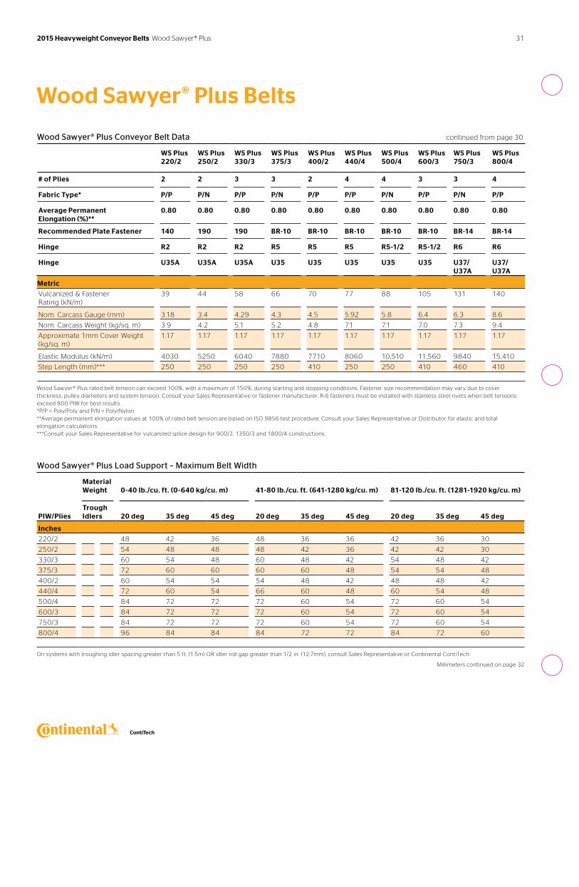
Wood Sawyer® Plus Conveyor Belt Data
WS Plus 220/2
WS Plus 250/2
WS Plus 330/3
WS Plus 375/3
WS Plus 400/2
WS Plus 440/4
WS Plus 500/4
WS Plus 600/3
WS Plus 750/3
WS Plus 800/4
# of Plies 2 2 3 3 2 4 4 3 3 4
Fabric Type* P/P P/N P/P P/N P/P P/P P/N P/P P/N P/P
Average Permanent Elongation (%)**
0.80 0.80 0.80 0.80 0.80 0.80 0.80 0.80 0.80 0.80
Recommended Fastener Plate 140 190 190 BR-10 BR-10 BR-10 BR-10 BR-10 BR-14 BR-14
Hinge R2 R2 R2 R5 R5 R5 R5-1/2 R5-1/2 R6 R6
Hinge U35A U35A U35A U35 U35 U35 U35 U35 U37/37A U37/U37A
Imperial
Vulcanized & Fastener Rating (PIW) 220 250 330 375 400 440 500 600 750 800
Nom. Carcass Gauge (in.) 0.125 0.135 0.169 0.169 0.178 0.233 0.229 0.251 0.246 0.340
Nom. Carcass Weight (lb./sq. ft.) 0.79 0.85 1.05 1.07 0.98 1.46 1.45 1.44 1.50 1.93
Approximate 1/32 in. Cover Weight (lb./sq. ft.)
0.19 0.19 0.19 0.19 0.19 0.19 0.19 0.19 0.19 0.19
Elastic Modulus (PIW) 23,000 30,000 34,500 45,000 44,000 46,000 60,000 66,000 56,200 88,000
Step Length (in.)*** 10 10 10 10 16 10 10 16 18 16
Wood Sawyer® Plus rated belt tension can exceed 100%, with a maximum of 150%, during starting and stopping conditions. Fastener size recommendation may vary due to cover thickness, pulley diameters and system tension. Consult your Sales Representative or fastener manufacturer. R-6 fasteners must be installed with stainless steel rivets when belt tensions exceed 800 PIW for best results. *P/P = Poly/Poly and P/N = Poly/Nylon **Average permanent elongation values at 100% of rated belt tension are based on ISO 9856 test procedure. Consult your Sales Representative or Distributor for elastic and total elongation calculations. ***Consult your Sales Representative for vulcanized splice design for 900/2, 1350/3 and 1800/4 constructions. Metric continued on page 31
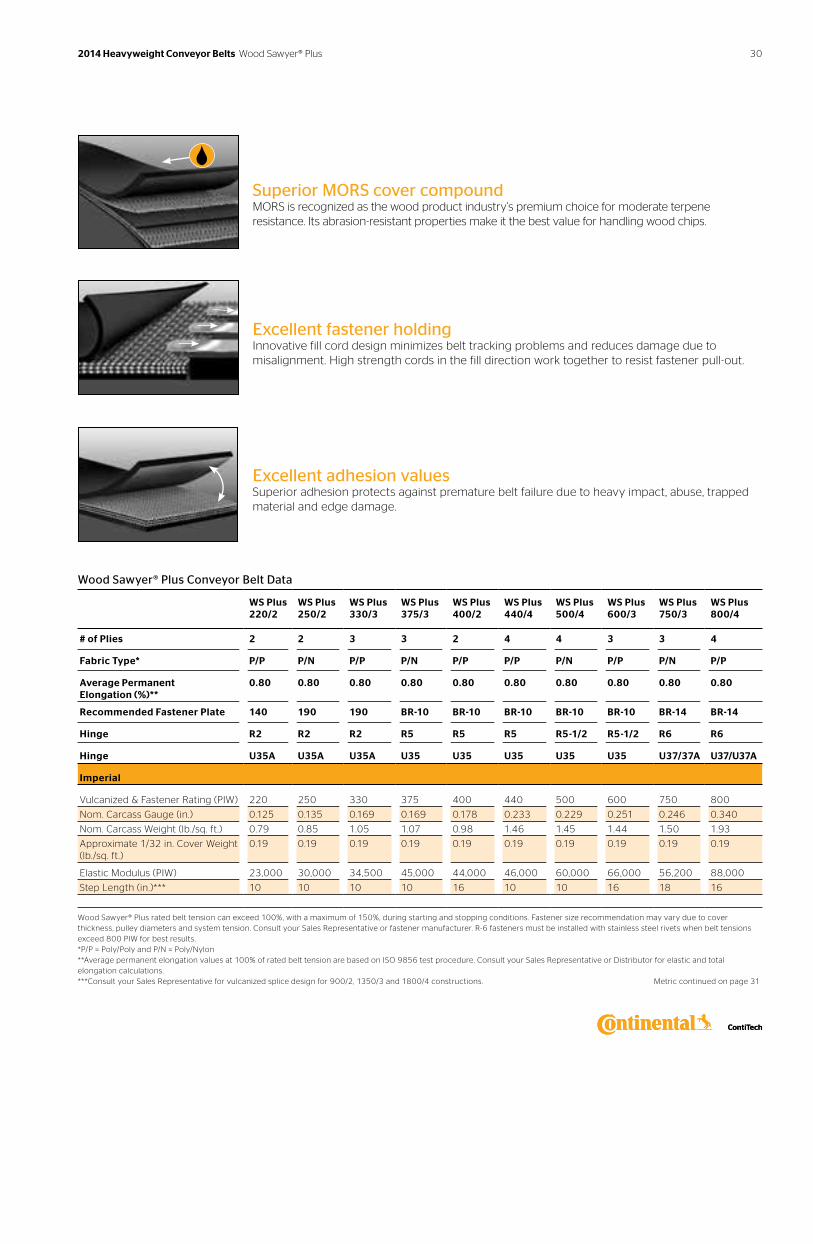
Superior MORS cover compoundMORS is recognized as the wood product industry’s premium choice for moderate terpene resistance. Its abrasion-resistant properties make it the best value for handling wood chips.
Excellent fastener holdingInnovative fill cord design minimizes belt tracking problems and reduces damage due to misalignment. High strength cords in the fill direction work together to resist fastener pull-out.
Excellent adhesion valuesSuperior adhesion protects against premature belt failure due to heavy impact, abuse, trapped material and edge damage.
30 2014 Heavyweight Conveyor Belts Wood Sawyer® Plus
Wood Sawyer® Plus Belts
Wood Sawyer® Plus Conveyor Belt Data continued from page 30
WS Plus 220/2
WS Plus 250/2
WS Plus 330/3
WS Plus 375/3
WS Plus 400/2
WS Plus 440/4
WS Plus 500/4
WS Plus 600/3
WS Plus 750/3
WS Plus 800/4
# of Plies 2 2 3 3 2 4 4 3 3 4
Fabric Type* P/P P/N P/P P/N P/P P/P P/N P/P P/N P/P
Average Permanent Elongation (%)**
0.80 0.80 0.80 0.80 0.80 0.80 0.80 0.80 0.80 0.80
Recommended Plate Fastener 140 190 190 BR-10 BR-10 BR-10 BR-10 BR-10 BR-14 BR-14
Hinge R2 R2 R2 R5 R5 R5 R5-1/2 R5-1/2 R6 R6
Hinge U35A U35A U35A U35 U35 U35 U35 U35 U37/U37A
U37/U37A
Metric
Vulcanized & Fastener Rating (kN/m)
39 44 58 66 70 77 88 105 131 140
Nom. Carcass Gauge (mm) 3.18 3.4 4.29 4.3 4.5 5.92 5.8 6.4 6.3 8.6
Nom. Carcass Weight (kg/sq. m) 3.9 4.2 5.1 5.2 4.8 7.1 7.1 7.0 7.3 9.4
Approximate 1mm Cover Weight (kg/sq. m)
1.17 1.17 1.17 1.17 1.17 1.17 1.17 1.17 1.17 1.17
Elastic Modulus (kN/m) 4030 5250 6040 7880 7710 8060 10,510 11,560 9840 15,410
Step Length (mm)*** 250 250 250 250 410 250 250 410 460 410
Wood Sawyer® Plus rated belt tension can exceed 100%, with a maximum of 150%, during starting and stopping conditions. Fastener size recommendation may vary due to cover thickness, pulley diameters and system tension. Consult your Sales Representative or fastener manufacturer. R-6 fasteners must be installed with stainless steel rivets when belt tensions exceed 800 PIW for best results. *P/P = Poly/Poly and P/N = Poly/Nylon **Average permanent elongation values at 100% of rated belt tension are based on ISO 9856 test procedure. Consult your Sales Representative or Distributor for elastic and total elongation calculations. ***Consult your Sales Representative for vulcanized splice design for 900/2, 1350/3 and 1800/4 constructions.
Wood Sawyer® Plus Load Support – Maximum Belt Width
Material Weight
0-40 lb./cu. ft. (0-640 kg/cu. m)
41-80 lb./cu. ft. (641-1280 kg/cu. m)
81-120 lb./cu. ft. (1281-1920 kg/cu. m)
PIW/Plies
Trough Idlers
20 deg
35 deg
45 deg
20 deg
35 deg
45 deg
20 deg
35 deg
45 deg
Inches
220/2 48 42 36 48 36 36 42 36 30
250/2 54 48 48 48 42 36 42 42 30
330/3 60 54 48 60 48 42 54 48 42
375/3 72 60 60 60 60 48 54 54 48
400/2 60 54 54 54 48 42 48 48 42
440/4 72 60 54 66 60 48 60 54 48
500/4 84 72 72 72 60 54 72 60 54
600/3 84 72 72 72 60 54 72 60 54
750/3 84 72 72 72 60 54 72 60 54
800/4 96 84 84 84 72 72 84 72 60
On systems with troughing idler spacing greater than 5 ft. (1.5m) OR idler roll gap greater than 1/2 in. (12.7mm), consult Sales Representative or Continental ContiTech.
Millimeters continued on page 32
31 2015 Heavyweight Conveyor Belts Wood Sawyer® Plus
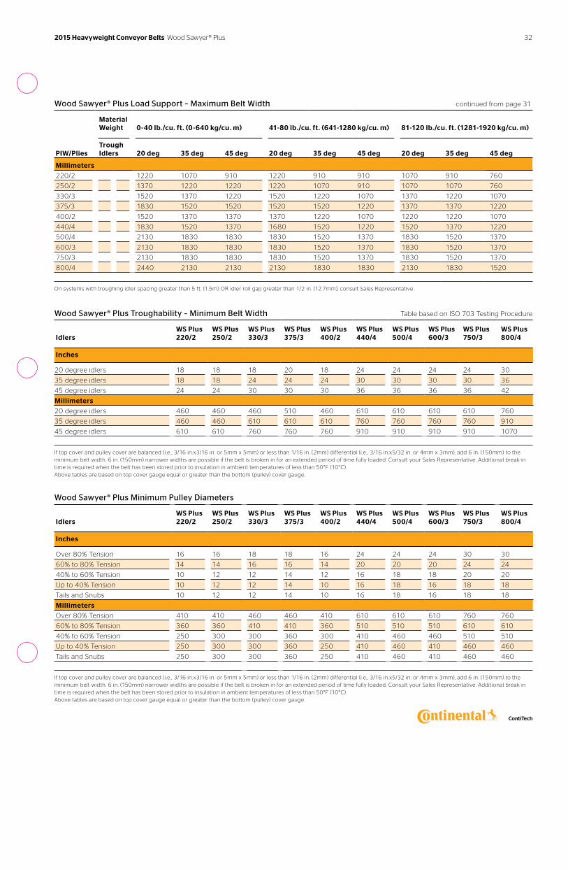
Wood Sawyer® Plus Load Support – Maximum Belt Width continued from page 31
Material Weight
0-40 lb./cu. ft. (0-640 kg/cu. m)
41-80 lb./cu. ft. (641-1280 kg/cu. m)
81-120 lb./cu. ft. (1281-1920 kg/cu. m)
PIW/Plies
Trough Idlers
20 deg
35 deg
45 deg
20 deg
35 deg
45 deg
20 deg
35 deg
45 deg
Millimeters
220/2 1220 1070 910 1220 910 910 1070 910 760
250/2 1370 1220 1220 1220 1070 910 1070 1070 760
330/3 1520 1370 1220 1520 1220 1070 1370 1220 1070
375/3 1830 1520 1520 1520 1520 1220 1370 1370 1220
400/2 1520 1370 1370 1370 1220 1070 1220 1220 1070
440/4 1830 1520 1370 1680 1520 1220 1520 1370 1220
500/4 2130 1830 1830 1830 1520 1370 1830 1520 1370
600/3 2130 1830 1830 1830 1520 1370 1830 1520 1370
750/3 2130 1830 1830 1830 1520 1370 1830 1520 1370
800/4 2440 2130 2130 2130 1830 1830 2130 1830 1520
On systems with troughing idler spacing greater than 5 ft. (1.5m) OR idler roll gap greater than 1/2 in. (12.7mm), consult Sales Representative.
Wood Sawyer® Plus Troughability – Minimum Belt Width Table based on ISO 703 Testing Procedure
Idlers
WS Plus 220/2
WS Plus 250/2
WS Plus 330/3
WS Plus 375/3
WS Plus 400/2
WS Plus 440/4
WS Plus 500/4
WS Plus 600/3
WS Plus 750/3
WS Plus 800/4
Inches
20 degree idlers 18 18 18 20 18 24 24 24 24 30
35 degree idlers 18 18 24 24 24 30 30 30 30 36
45 degree idlers 24 24 30 30 30 36 36 36 36 42
Millimeters
20 degree idlers 460 460 460 510 460 610 610 610 610 760
35 degree idlers 460 460 610 610 610 760 760 760 760 910
45 degree idlers 610 610 760 760 760 910 910 910 910 1070
If top cover and pulley cover are balanced (i.e. , 3/16 in.x3/16 in. or 5mm x 5mm) or less than 1/16 in. (2mm) differential (i.e. , 3/16 in.x5/32 in. or 4mm x 3mm), add 6 in. (150mm) to the minimum belt width. 6 in. (150mm) narrower widths are possible if the belt is broken in for an extended period of time fully loaded. Consult your Sales Representative. Additional break-in time is required when the belt has been stored prior to insulation in ambient temperatures of less than 50°F (10°C). Above tables are based on top cover gauge equal or greater than the bottom (pulley) cover gauge.
Wood Sawyer® Plus Minimum Pulley Diameters
Idlers
WS Plus 220/2
WS Plus 250/2
WS Plus 330/3
WS Plus 375/3
WS Plus 400/2
WS Plus 440/4
WS Plus 500/4
WS Plus 600/3
WS Plus 750/3
WS Plus 800/4
Inches
Over 80% Tension 16 16 18 18 16 24 24 24 30 30
60% to 80% Tension 14 14 16 16 14 20 20 20 24 24
40% to 60% Tension 10 12 12 14 12 16 18 18 20 20
Up to 40% Tension 10 12 12 14 10 16 18 16 18 18
Tails and Snubs 10 12 12 14 10 16 18 16 18 18
Millimeters
Over 80% Tension 410 410 460 460 410 610 610 610 760 760
60% to 80% Tension 360 360 410 410 360 510 510 510 610 610
40% to 60% Tension 250 300 300 360 300 410 460 460 510 510
Up to 40% Tension 250 300 300 360 250 410 460 410 460 460
Tails and Snubs 250 300 300 360 250 410 460 410 460 460
If top cover and pulley cover are balanced (i.e. , 3/16 in.x3/16 in. or 5mm x 5mm) or less than 1/16 in. (2mm) differential (i.e. , 3/16 in.x5/32 in. or 4mm x 3mm), add 6 in. (150mm) to the minimum belt width. 6 in. (150mm) narrower widths are possible if the belt is broken in for an extended period of time fully loaded. Consult your Sales Representative. Additional break-in time is required when the belt has been stored prior to insulation in ambient temperatures of less than 50°F (10°C). Above tables are based on top cover gauge equal or greater than the bottom (pulley) cover gauge.
32 2015 Heavyweight Conveyor Belts Wood Sawyer® Plus
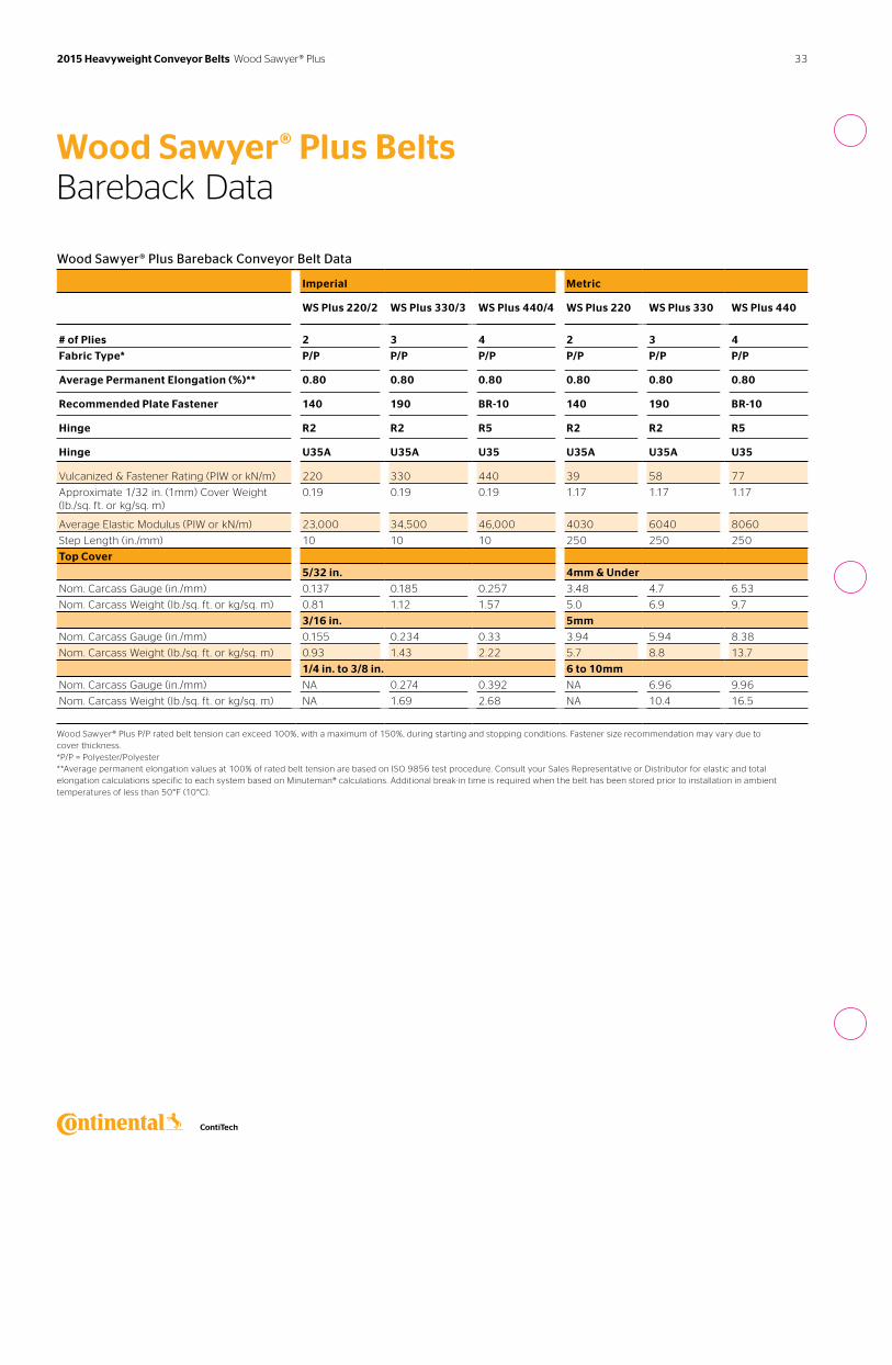
Wood Sawyer® Plus BeltsBareback Data
Wood Sawyer® Plus Bareback Conveyor Belt Data
Imperial Metric
WS Plus 220/2 WS Plus 330/3 WS Plus 440/4 WS Plus 220 WS Plus 330 WS Plus 440
# of Plies 2 3 4 2 3 4
Fabric Type* P/P P/P P/P P/P P/P P/P
Average Permanent Elongation (%)** 0.80 0.80 0.80 0.80 0.80 0.80
Recommended Plate Fastener 140 190 BR-10 140 190 BR-10
Hinge R2 R2 R5 R2 R2 R5
Hinge U35A U35A U35 U35A U35A U35
Vulcanized & Fastener Rating (PIW or kN/m) 220 330 440 39 58 77
Approximate 1/32 in. (1mm) Cover Weight (lb./sq. ft. or kg/sq. m)
0.19 0.19 0.19 1.17 1.17 1.17
Average Elastic Modulus (PIW or kN/m) 23,000 34,500 46,000 4030 6040 8060
Step Length (in./mm) 10 10 10 250 250 250
Top Cover
5/32 in. 4mm & Under
Nom. Carcass Gauge (in./mm) 0.137 0.185 0.257 3.48 4.7 6.53
Nom. Carcass Weight (lb./sq. ft. or kg/sq. m) 0.81 1.12 1.57 5.0 6.9 9.7
3/16 in. 5mm
Nom. Carcass Gauge (in./mm) 0.155 0.234 0.33 3.94 5.94 8.38
Nom. Carcass Weight (lb./sq. ft. or kg/sq. m) 0.93 1.43 2.22 5.7 8.8 13.7
1/4 in. to 3/8 in. 6 to 10mm
Nom. Carcass Gauge (in./mm) NA 0.274 0.392 NA 6.96 9.96
Nom. Carcass Weight (lb./sq. ft. or kg/sq. m) NA 1.69 2.68 NA 10.4 16.5
Wood Sawyer® Plus P/P rated belt tension can exceed 100%, with a maximum of 150%, during starting and stopping conditions. Fastener size recommendation may vary due to cover thickness. *P/P = Polyester/Polyester **Average permanent elongation values at 100% of rated belt tension are based on ISO 9856 test procedure. Consult your Sales Representative or Distributor for elastic and total elongation calculations specific to each system based on Minuteman® calculations. Additional break-in time is required when the belt has been stored prior to installation in ambient temperatures of less than 50°F (10°C).
33 2015 Heavyweight Conveyor Belts Wood Sawyer® Plus
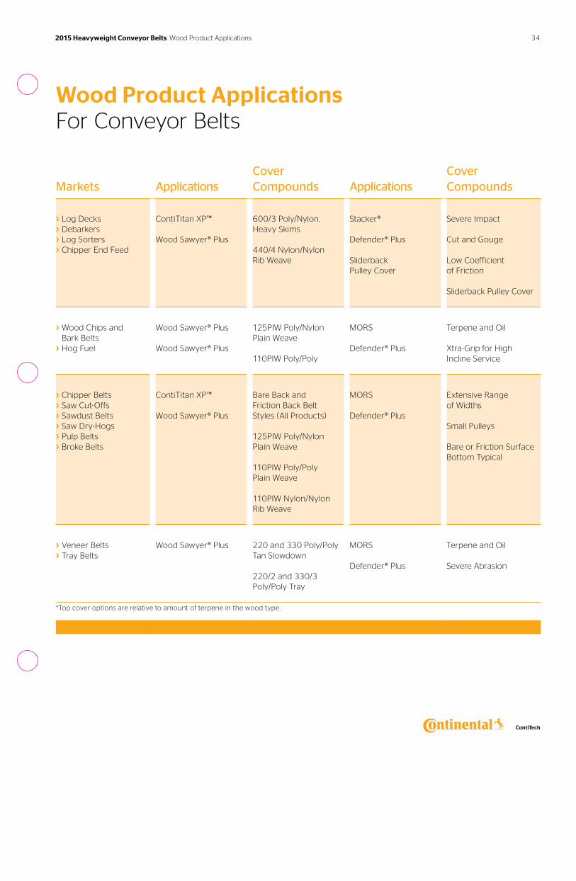
Markets ApplicationsCover Compounds Applications
Cover Compounds
› Log Decks› Debarkers› Log Sorters› Chipper End Feed
ContiTitan XP™
Wood Sawyer® Plus
600/3 Poly/Nylon, Heavy Skims
440/4 Nylon/Nylon Rib Weave
Stacker®
Defender® Plus
Sliderback Pulley Cover
Severe Impact
Cut and Gouge
Low Coefficient of Friction
Sliderback Pulley Cover
› Wood Chips and Bark Belts
› Hog Fuel
Wood Sawyer® Plus
Wood Sawyer® Plus
125PIW Poly/Nylon Plain Weave
110PIW Poly/Poly
MORS
Defender® Plus
Terpene and Oil
Xtra-Grip for High Incline Service
› Chipper Belts› Saw Cut-Offs› Sawdust Belts› Saw Dry-Hogs› Pulp Belts› Broke Belts
ContiTitan XP™
Wood Sawyer® Plus
Bare Back and Friction Back Belt Styles (All Products)
125PIW Poly/Nylon Plain Weave
110PIW Poly/Poly Plain Weave
110PIW Nylon/NylonRib Weave
MORS
Defender® Plus
Extensive Range of Widths
Small Pulleys
Bare or Friction Surface Bottom Typical
› Veneer Belts › Tray Belts
Wood Sawyer® Plus 220 and 330 Poly/Poly Tan Slowdown
220/2 and 330/3 Poly/Poly Tray
MORS
Defender® Plus
Terpene and Oil
Severe Abrasion
*Top cover options are relative to amount of terpene in the wood type.
Wood Product ApplicationsFor Conveyor Belts
34 2015 Heavyweight Conveyor Belts Wood Product Applications
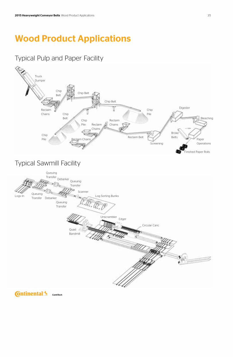
Truck
Dumper
Reclaim
Chains
Chip
Belt
Chip
Belt
Chip Belt
Chip
Pile
Chip
Pile
Chip
Pile
Reclaim
Chains
Reclaim Chains
Reclaim
Chains
Reclaim Belt
Screening
Digester
Broke
BeltsPaper
Operations
Finished Paper Rolls
Bleaching
Queuing
TransferDebarker
Queuing
Transfer
Queuing
Transfer
Queuing
Transfer
Log Sorting Bunks
Quad
Bandmill
UnscramblerEdger
Circular Canc
Scanner
Debarker
Chip Belt
Logs In
Wood Product Applications
Typical Pulp and Paper Facility
Typical Sawmill Facility
35 2015 Heavyweight Conveyor Belts Wood Product Applications
Markets Applications Cover Compounds
› Agriculture› Bulk Handling Terminals› Grain
› Grain Elevator › Grain Storage› Grain Transfer
› Pathfinder® Arctic› Pathfinder® Supreme› PF+ CSA**Meets Canadian specifications.
See pages 72-77 for more specific details.
Get a lower cost-per-ton conveyed. Tension Range: 250 to 1250 PIW
Pathfinder® Plus Belts
Continental ContiTech Pathfinder® Plus is a reinforced belt designed to stand up to the unique operating conditions of grain handling facilities. Pathfinder®’s exceptionally low electrical resistance and superior oil resistance properties provide excellent operational safety and long life.
Features & Benefits
High ultimate strengthPathfinder® is designed to withstand harsh operating conditions. The tensile force required to break a 48 in. Pathfinder 375 PIW belt is 180,000 pounds.
Low belt elongationLow belt elongation increases productivity and minimizes downtime spent re-splicing grain belting. Permanent elongation averages 0.8% at 100% of rated operating tension.
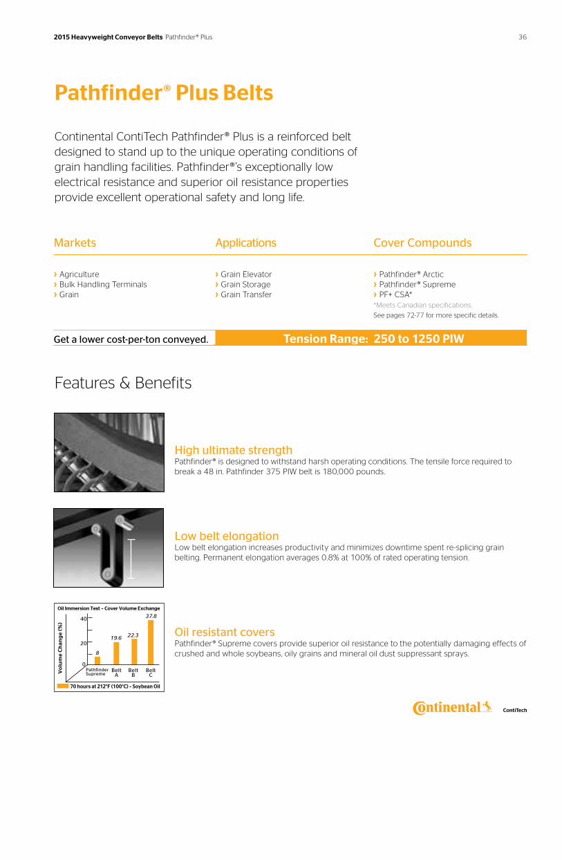
Oil resistant coversPathfinder® Supreme covers provide superior oil resistance to the potentially damaging effects of crushed and whole soybeans, oily grains and mineral oil dust suppressant sprays.
70 hours at 212°F (100°C) – Soybean Oil
Pathfinder Supreme
Belt A
0
20
40
8
19.6 22.3
37.8
Vo
lum
e C
ha
ng
e (%
)
Oil Immersion Test – Cover Volume Exchange
Belt B
Belt C
36 2015 Heavyweight Conveyor Belts Pathfinder® Plus
Pathfinder® Plus Belts
Features & Benefits
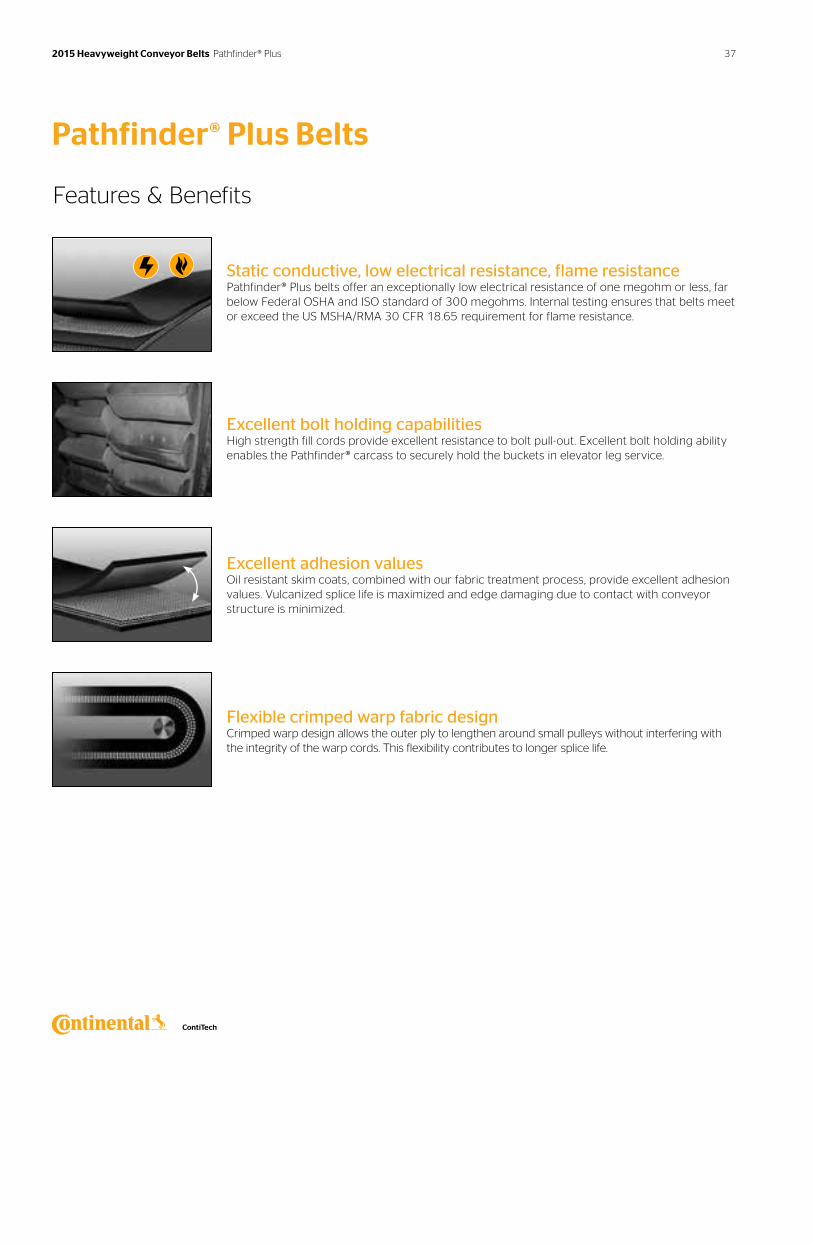
Static conductive, low electrical resistance, flame resistancePathfinder® Plus belts offer an exceptionally low electrical resistance of one megohm or less, far below Federal OSHA and ISO standard of 300 megohms. Internal testing ensures that belts meet or exceed the US MSHA/RMA 30 CFR 18.65 requirement for flame resistance.
Excellent bolt holding capabilitiesHigh strength fill cords provide excellent resistance to bolt pull-out. Excellent bolt holding ability enables the Pathfinder® carcass to securely hold the buckets in elevator leg service.
Excellent adhesion valuesOil resistant skim coats, combined with our fabric treatment process, provide excellent adhesion values. Vulcanized splice life is maximized and edge damaging due to contact with conveyor structure is minimized.
Flexible crimped warp fabric designCrimped warp design allows the outer ply to lengthen around small pulleys without interfering with the integrity of the warp cords. This flexibility contributes to longer splice life.
37 2015 Heavyweight Conveyor Belts Pathfinder® Plus
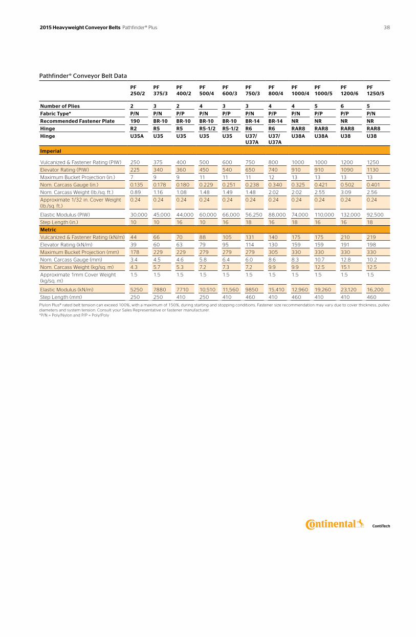
Pathfinder® Conveyor Belt Data
PF 250/2
PF 375/3
PF 400/2
PF 500/4
PF 600/3
PF 750/3
PF 800/4
PF 1000/4
PF 1000/5
PF 1200/6
PF 1250/5
Number of Plies 2 3 2 4 3 3 4 4 5 6 5
Fabric Type* P/N P/N P/P P/N P/P P/N P/P P/N P/P P/P P/N
Recommended Fastener Plate 190 BR-10 BR-10 BR-10 BR-10 BR-14 BR-14 NR NR NR NR
Hinge R2 R5 R5 R5-1/2 R5-1/2 R6 R6 RAR8 RAR8 RAR8 RAR8
Hinge U35A U35 U35 U35 U35 U37/U37A
U37/U37A
U38A U38A U38 U38
Imperial
Vulcanized & Fastener Rating (PIW) 250 375 400 500 600 750 800 1000 1000 1200 1250
Elevator Rating (PIW) 225 340 360 450 540 650 740 910 910 1090 1130
Maximum Bucket Projection (in.) 7 9 9 11 11 11 12 13 13 13 13
Nom. Carcass Gauge (in.) 0.135 0.178 0.180 0.229 0.251 0.238 0.340 0.325 0.421 0.502 0.401
Nom. Carcass Weight (lb./sq. ft.) 0.89 1.16 1.08 1.48 1.49 1.48 2.02 2.02 2.55 3.09 2.56
Approximate 1/32 in. Cover Weight (lb./sq. ft.)
0.24 0.24 0.24 0.24 0.24 0.24 0.24 0.24 0.24 0.24 0.24
Elastic Modulus (PIW) 30,000 45,000 44,000 60,000 66,000 56,250 88,000 74,000 110,000 132,000 92,500
Step Length (in.) 10 10 16 10 16 18 16 18 16 16 18
Metric
Vulcanized & Fastener Rating (kN/m) 44 66 70 88 105 131 140 175 175 210 219
Elevator Rating (kN/m) 39 60 63 79 95 114 130 159 159 191 198
Maximum Bucket Projection (mm) 178 229 229 279 279 279 305 330 330 330 330
Nom. Carcass Gauge (mm) 3.4 4.5 4.6 5.8 6.4 6.0 8.6 8.3 10.7 12.8 10.2
Nom. Carcass Weight (kg/sq. m) 4.3 5.7 5.3 7.2 7.3 7.2 9.9 9.9 12.5 15.1 12.5
Approximate 1mm Cover Weight (kg/sq. m)
1.5 1.5 1.5 1.5 1.5 1.5 1.5 1.5 1.5 1.5 1.5
Elastic Modulus (kN/m) 5250 7880 7710 10,510 11,560 9850 15,410 12,960 19,260 23,120 16,200
Step Length (mm) 250 250 410 250 410 460 410 460 410 410 460
Plylon Plus® rated belt tension can exceed 100%, with a maximum of 150%, during starting and stopping conditions. Fastener size recommendation may vary due to cover thickness, pulley diameters and system tension. Consult your Sales Representative or fastener manufacturer. *P/N = Poly/Nylon and P/P = Poly/Poly
38 2015 Heavyweight Conveyor Belts Pathfinder® Plus
Pathfinder® Plus Belts
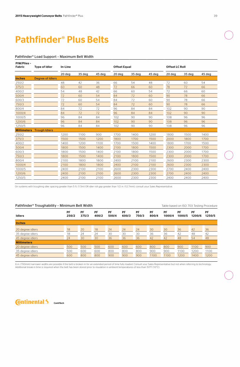
Pathfinder® Troughability – Minimum Belt Width Table based on ISO 703 Testing Procedure
Idlers
PF 250/2
PF 375/3
PF 400/2
PF 500/4
PF 600/3
PF 750/3
PF 800/4
PF 1000/4
PF 1000/5
PF 1200/6
PF 1250/5
Inches
20 degree idlers 18 20 18 24 24 24 30 30 36 42 36
35 degree idlers 18 24 24 30 30 30 36 36 42 48 42
45 degree idlers 24 30 30 36 36 36 42 42 48 54 48
Millimeters
20 degree idlers 500 500 500 600 600 600 800 800 900 1100 900
35 degree idlers 500 600 600 800 800 800 900 900 1100 1200 1100
45 degree idlers 600 800 800 900 900 900 1100 1100 1200 1400 1200
6 in. (150mm) narrower widths are possible if the belt is broken in for an extended period of time fully loaded. Consult your Sales Representative but not when referring to technology. Additional break-in time is required when the belt has been stored prior to insulation in ambient temperatures of less than 50°F (10°C).
Pathfinder® Load Support – Maximum Belt Width
PIW/Plies – Fabric
Type of Idler
In-Line
Offset Equal
Offset LC Roll
20 deg 35 deg 45 deg 20 deg 35 deg 45 deg 20 deg 35 deg 45 deg
Inches Degree of Idlers
250/2 48 42 36 66 54 48 72 60 54
375/3 60 60 48 72 66 60 78 72 66
400/2 54 48 42 66 60 54 72 66 60
500/4 72 60 54 84 72 60 90 78 66
600/3 72 60 54 84 72 60 90 78 66
750/3 72 60 54 84 72 60 90 78 66
800/4 84 72 72 96 84 84 102 90 90
1000/4 84 72 72 96 84 84 102 90 90
1000/5 96 84 84 102 90 90 108 96 96
1200/6 96 84 84 102 90 90 108 96 96
1250/5 96 84 84 102 90 90 108 96 96
Millimeters Trough Idlers
250/2 1200 1100 900 1700 1400 1200 1800 1500 1400
375/3 1500 1500 1200 1800 1700 1500 2000 1800 1700
400/2 1400 1200 1100 1700 1500 1400 1800 1700 1500
500/4 1800 1500 1400 2100 1800 1500 2300 2000 1700
600/3 1800 1500 1400 2100 1800 1500 2300 2000 1700
750/3 1800 1500 1400 2100 1800 1500 2300 2000 1700
800/4 2100 1800 1800 2400 2100 2100 2600 2300 2300
1000/4 2100 1800 1800 2400 2100 2100 2600 2300 2300
1000/5 2400 2100 2100 2600 2300 2300 2700 2400 2400
1200/6 2400 2100 2100 2600 2300 2300 2700 2400 2400
1250/5 2400 2100 2100 2600 2300 2300 2400 2400 2400
On systems with troughing idler spacing greater than 5 ft. (1.5m) OR idler roll gap greater than 1/2 in. (12.7mm), consult your Sales Representative.
39 2015 Heavyweight Conveyor Belts Pathfinder® Plus
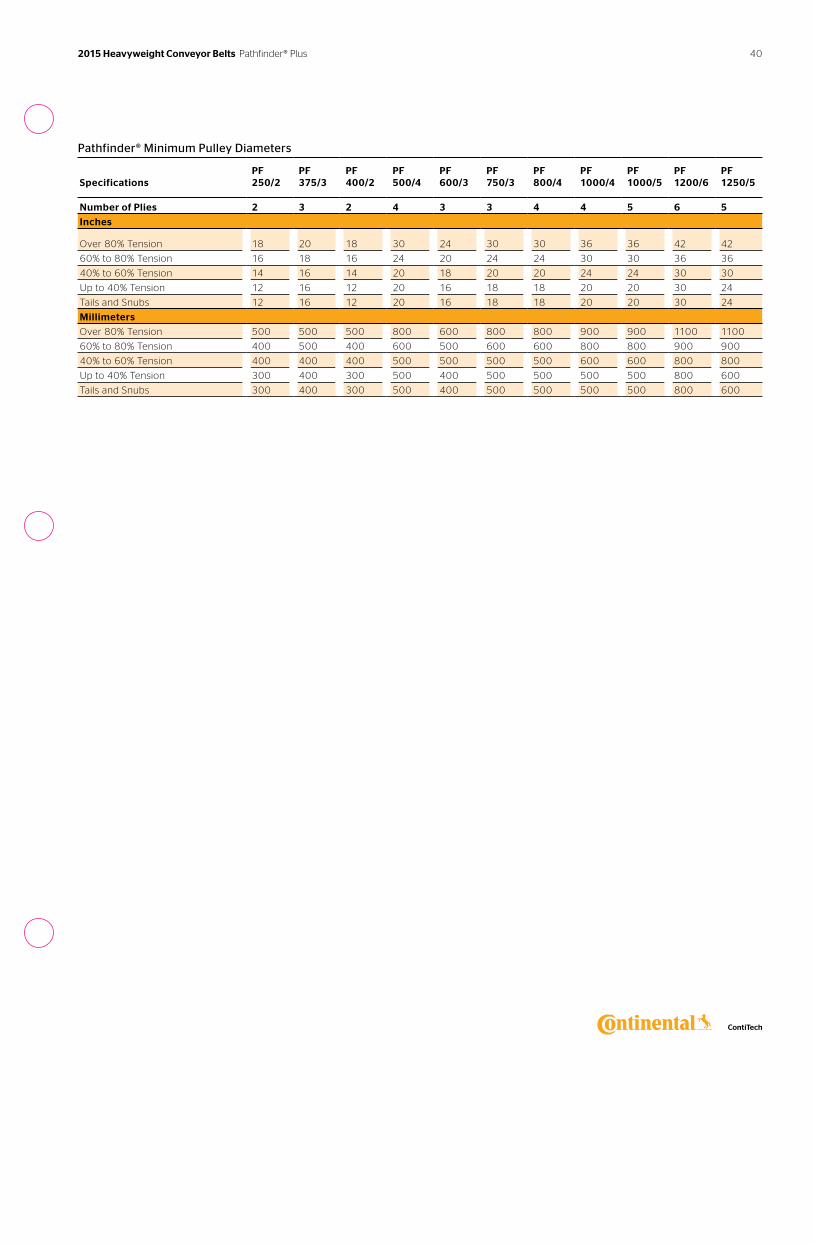
Pathfinder® Minimum Pulley Diameters
Specifications
PF 250/2
PF 375/3
PF 400/2
PF 500/4
PF 600/3
PF 750/3
PF 800/4
PF 1000/4
PF 1000/5
PF 1200/6
PF 1250/5
Number of Plies 2 3 2 4 3 3 4 4 5 6 5
Inches
Over 80% Tension 18 20 18 30 24 30 30 36 36 42 42
60% to 80% Tension 16 18 16 24 20 24 24 30 30 36 36
40% to 60% Tension 14 16 14 20 18 20 20 24 24 30 30
Up to 40% Tension 12 16 12 20 16 18 18 20 20 30 24
Tails and Snubs 12 16 12 20 16 18 18 20 20 30 24
Millimeters
Over 80% Tension 500 500 500 800 600 800 800 900 900 1100 1100
60% to 80% Tension 400 500 400 600 500 600 600 800 800 900 900
40% to 60% Tension 400 400 400 500 500 500 500 600 600 800 800
Up to 40% Tension 300 400 300 500 400 500 500 500 500 800 600
Tails and Snubs 300 400 300 500 400 500 500 500 500 800 600
40 2015 Heavyweight Conveyor Belts Pathfinder® Plus
2015 Heavyweight Conveyor Belts Underground
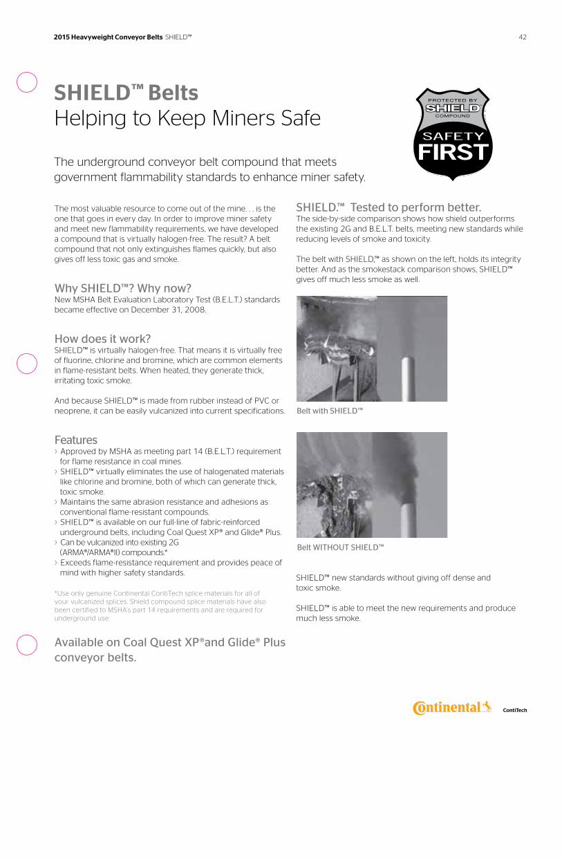
The most valuable resource to come out of the mine. . . is the one that goes in every day. In order to improve miner safety and meet new flammability requirements, we have developed a compound that is virtually halogen-free. The result? A belt compound that not only extinguishes flames quickly, but also gives off less toxic gas and smoke.
Why SHIELD™? Why now?New MSHA Belt Evaluation Laboratory Test (B.E.L.T.) standards became effective on December 31, 2008.
How does it work? SHIELD™ is virtually halogen-free. That means it is virtually free of fluorine, chlorine and bromine, which are common elements in flame-resistant belts. When heated, they generate thick, irritating toxic smoke.
And because SHIELD™ is made from rubber instead of PVC or neoprene, it can be easily vulcanized into current specifications.
Features› Approved by MSHA as meeting part 14 (B.E.L.T.) requirement
for flame resistance in coal mines.› SHIELD™ virtually eliminates the use of halogenated materials
like chlorine and bromine, both of which can generate thick, toxic smoke.
› Maintains the same abrasion resistance and adhesions as conventional flame-resistant compounds.
› SHIELD™ is available on our full-line of fabric-reinforced underground belts, including Coal Quest XP® and Glide® Plus.
› Can be vulcanized into existing 2G (ARMA®/ARMA®II) compounds.*
› Exceeds flame-resistance requirement and provides peace of mind with higher safety standards.
*Use only genuine Continental ContiTech splice materials for all of your vulcanized splices. Shield compound splice materials have also been certified to MSHA’s part 14 requirements and are required for underground use.
Available on Coal Quest XP®and Glide® Plus conveyor belts.
SHIELD.™ Tested to perform better.The side-by-side comparison shows how shield outperforms the existing 2G and B.E.L.T. belts, meeting new standards while reducing levels of smoke and toxicity.
The belt with SHIELD,™ as shown on the left, holds its integrity better. And as the smokestack comparison shows, SHIELD™ gives off much less smoke as well.
SHIELD™ new standards without giving off dense and toxic smoke.
SHIELD™ is able to meet the new requirements and produce much less smoke.
SHIELD™ BeltsHelping to Keep Miners Safe
The underground conveyor belt compound that meets government flammability standards to enhance miner safety.
Belt with SHIELD™
Belt WITHOUT SHIELD™
42 2015 Heavyweight Conveyor Belts SHIELD™
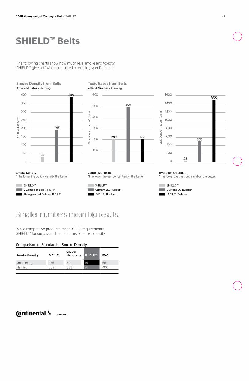
43 2015 Heavyweight Conveyor Belts SHIELD™
The following charts show how much less smoke and toxicity SHIELD™ gives off when compared to existing specifications.
Smaller numbers mean big results.
While competitive products meet B.E.L.T. requirements, SHIELD™ far surpasses them in terms of smoke density.
Comparison of Standards – Smoke Density
Smoke Density
B.E.L.T.
Global Neoprene
SHIELD™
PVC
Smoldering 125 59 15 66
Flaming 389 383 28 400
400
350
300
250
200
150
100
50
0
Op
tical
Den
sity
*
Smoke Density from Belts After 4 Minutes – Flaming
Smoke Density *The lower the optical density the better
SHIELD™
2G Rubber Belt (ARMA®)
Halogenated Rubber B.E.L.T.
28
195
389
Gas
Co
nce
ntr
atio
n*
(pp
m)
Toxic Gases from Belts After 4 Minutes – Flaming
Carbon Monoxide *The lower the gas concentration the better
SHIELD™
Current 2G Rubber
B.E.L.T. Rubber
200
500
200
600
500
400
300
200
100
Gas
Co
nce
ntr
atio
n*
(pp
m)
Hydrogen Chloride *The lower the gas concentration the better
SHIELD™
Current 2G Rubber
B.E.L.T. Rubber
500
15001600
1400
1200
1000
800
600
400
200
025
SHIELD™ Belts
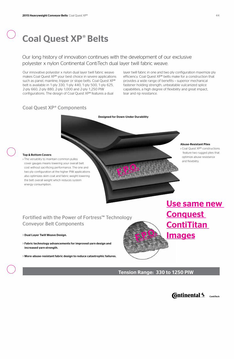
44
Coal Quest XP® Belts
Our long history of innovation continues with the development of our exclusive polyester x nylon Continental ContiTech dual layer twill fabric weave.
Our innovative polyester x nylon dual layer twill fabric weave makes Coal Quest XP® your best choice in severe applications such as panel, mainline, tripper or slope belts. Coal Quest XP® belt is available in 1-ply 330, 1-ply 440, 1-ply 500, 1-ply 625, 2-ply 660, 2-ply 880, 2-ply 1,000 and 2-ply 1,250 PIW configurations. The design of Coal Quest XP® features a dual
layer twill fabric in one and two ply configuration maximize ply efficiency. Coal Quest XP® belts make for a construction that provides a wide range of benefits – superior mechanical fastener holding strength, unbeatable vulcanized splice capabilities, a high degree of flexibility and great impact, tear and rip resistance.
Coal Quest XP® Components
Abuse-Resistant Plies
› Coal Quest XP® constructions
feature two rugged plies that
optimize abuse resistance
and flexibility.
Fortified with the Power of Fortress™ Technology Conveyor Belt Components
› Dual Layer Twill Weave Design.
› Fabric technology advancements for improved yarn design and
increased yarn strength.
› More-abuse-resistant fabric design to reduce catastrophic failures.
Top & Bottom Covers
› The versatility to maintain common pulley
cover gauges means lowering your overall belt
cost without sacrificing performance. The one and
two ply configuration at the higher PIW applications
also optimizes skim coat and fabric weight lowering
the belt overall weight which reduces system
energy consumption.
Designed for Down-Under Durability
Tension Range: 330 to 1250 PIW
F.P.O.
F.P.O.
Use same new Conquest ContiTitan Images
2015 Heavyweight Conveyor Belts Coal Quest XP®
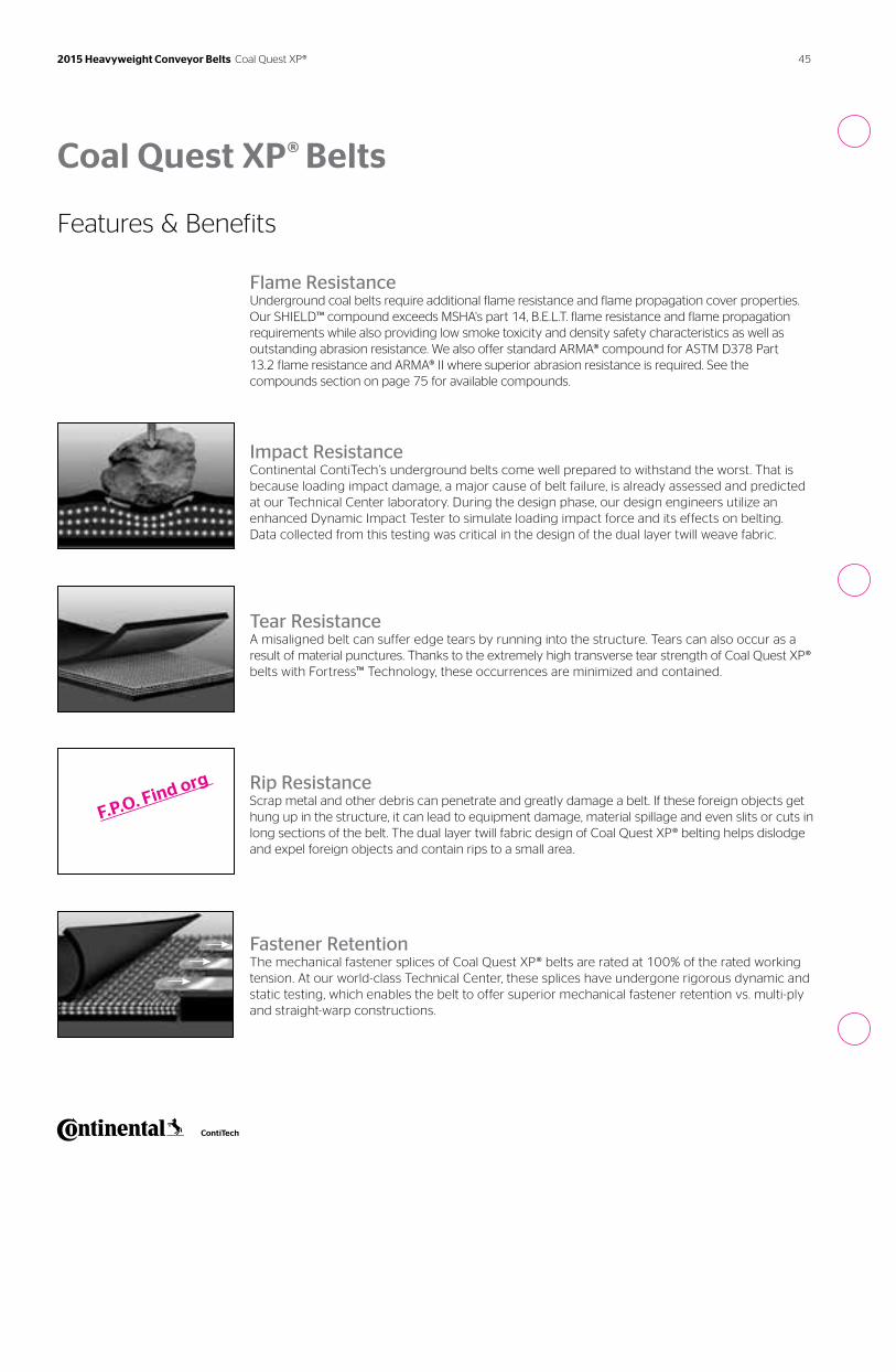
45 2015 Heavyweight Conveyor Belts Coal Quest XP®
Coal Quest XP® Belts
Features & Benefits
Flame ResistanceUnderground coal belts require additional flame resistance and flame propagation cover properties. Our SHIELD™ compound exceeds MSHA's part 14, B.E.L.T. flame resistance and flame propagation requirements while also providing low smoke toxicity and density safety characteristics as well as outstanding abrasion resistance. We also offer standard ARMA® compound for ASTM D378 Part 13.2 flame resistance and ARMA® II where superior abrasion resistance is required. See the compounds section on page 75 for available compounds.
F.P.O. Find org
Tear ResistanceA misaligned belt can suffer edge tears by running into the structure. Tears can also occur as a result of material punctures. Thanks to the extremely high transverse tear strength of Coal Quest XP® belts with Fortress™ Technology, these occurrences are minimized and contained.
Rip ResistanceScrap metal and other debris can penetrate and greatly damage a belt. If these foreign objects get hung up in the structure, it can lead to equipment damage, material spillage and even slits or cuts in long sections of the belt. The dual layer twill fabric design of Coal Quest XP® belting helps dislodge and expel foreign objects and contain rips to a small area.
Fastener RetentionThe mechanical fastener splices of Coal Quest XP® belts are rated at 100% of the rated working tension. At our world-class Technical Center, these splices have undergone rigorous dynamic and static testing, which enables the belt to offer superior mechanical fastener retention vs. multi-ply and straight-warp constructions.
Impact ResistanceContinental ContiTech’s underground belts come well prepared to withstand the worst. That is because loading impact damage, a major cause of belt failure, is already assessed and predicted at our Technical Center laboratory. During the design phase, our design engineers utilize an enhanced Dynamic Impact Tester to simulate loading impact force and its effects on belting. Data collected from this testing was critical in the design of the dual layer twill weave fabric.
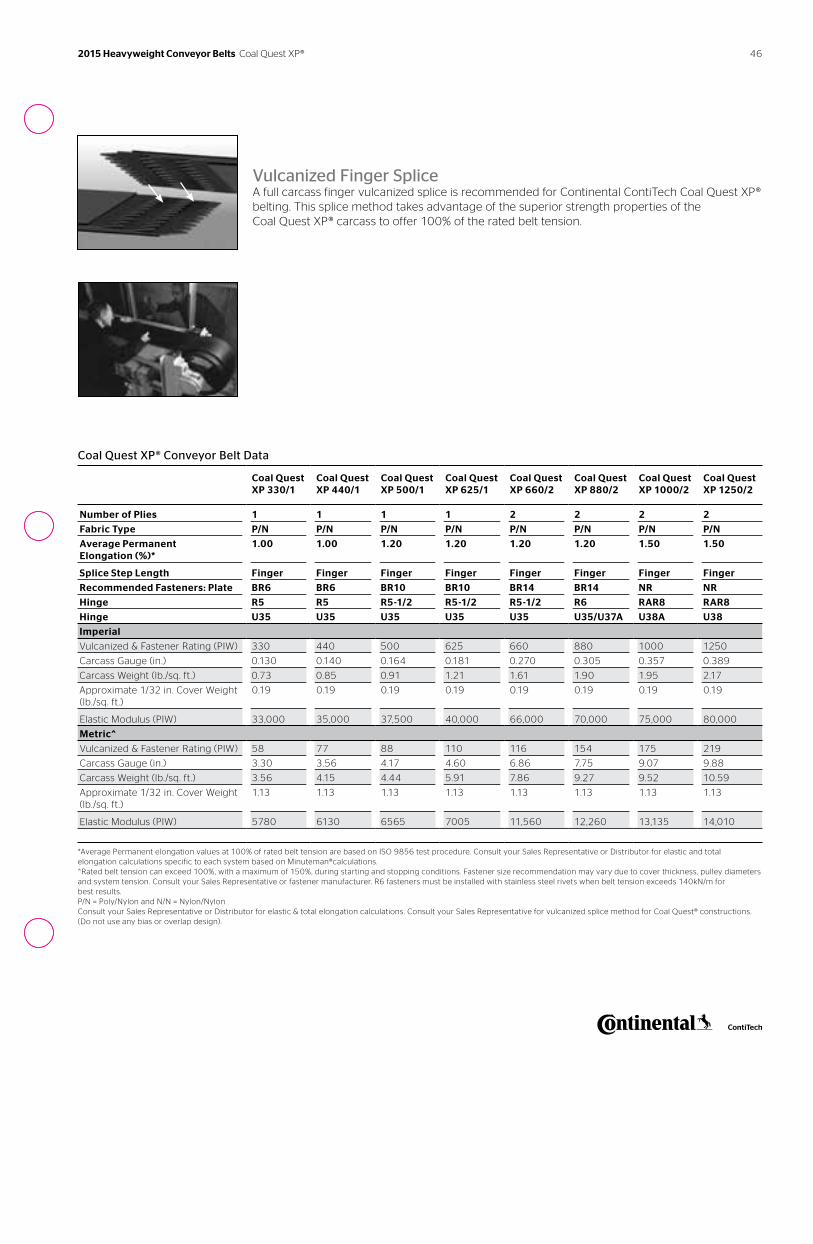
46
Coal Quest XP® Conveyor Belt Data
Coal Quest XP 330/1
Coal Quest XP 440/1
Coal Quest XP 500/1
Coal Quest XP 625/1
Coal Quest XP 660/2
Coal Quest XP 880/2
Coal Quest XP 1000/2
Coal Quest XP 1250/2
Number of Plies 1 1 1 1 2 2 2 2
Fabric Type P/N P/N P/N P/N P/N P/N P/N P/N
Average Permanent Elongation (%)*
1.00 1.00 1.20 1.20 1.20 1.20 1.50 1.50
Splice Step Length Finger Finger Finger Finger Finger Finger Finger Finger
Recommended Fasteners: Plate BR6 BR6 BR10 BR10 BR14 BR14 NR NR
Hinge R5 R5 R5-1/2 R5-1/2 R5-1/2 R6 RAR8 RAR8
Hinge U35 U35 U35 U35 U35 U35/U37A U38A U38
Imperial
Vulcanized & Fastener Rating (PIW) 330 440 500 625 660 880 1000 1250
Carcass Gauge (in.) 0.130 0.140 0.164 0.181 0.270 0.305 0.357 0.389
Carcass Weight (lb./sq. ft.) 0.73 0.85 0.91 1.21 1.61 1.90 1.95 2.17
Approximate 1/32 in. Cover Weight (lb./sq. ft.)
0.19 0.19 0.19 0.19 0.19 0.19 0.19 0.19
Elastic Modulus (PIW) 33,000 35,000 37,500 40,000 66,000 70,000 75,000 80,000
Metric^
Vulcanized & Fastener Rating (PIW) 58 77 88 110 116 154 175 219
Carcass Gauge (in.) 3.30 3.56 4.17 4.60 6.86 7.75 9.07 9.88
Carcass Weight (lb./sq. ft.) 3.56 4.15 4.44 5.91 7.86 9.27 9.52 10.59
Approximate 1/32 in. Cover Weight (lb./sq. ft.)
1.13 1.13 1.13 1.13 1.13 1.13 1.13 1.13
Elastic Modulus (PIW) 5780 6130 6565 7005 11,560 12,260 13,135 14,010
*Average Permanent elongation values at 100% of rated belt tension are based on ISO 9856 test procedure. Consult your Sales Representative or Distributor for elastic and total elongation calculations specific to each system based on Minuteman®calculations. ^Rated belt tension can exceed 100%, with a maximum of 150%, during starting and stopping conditions. Fastener size recommendation may vary due to cover thickness, pulley diameters and system tension. Consult your Sales Representative or fastener manufacturer. R6 fasteners must be installed with stainless steel rivets when belt tension exceeds 140kN/m for best results. P/N = Poly/Nylon and N/N = Nylon/Nylon Consult your Sales Representative or Distributor for elastic & total elongation calculations. Consult your Sales Representative for vulcanized splice method for Coal Quest® constructions. (Do not use any bias or overlap design).
Vulcanized Finger SpliceA full carcass finger vulcanized splice is recommended for Continental ContiTech Coal Quest XP® belting. This splice method takes advantage of the superior strength properties of the Coal Quest XP® carcass to offer 100% of the rated belt tension.
2015 Heavyweight Conveyor Belts Coal Quest XP®
47 2015 Heavyweight Conveyor Belts Coal Quest XP®
Coal Quest XP® Load Support – Maximum Belt Width
Imperial Metric
Material Weight 0-65 lb./cu. ft. 65-100 lb./cu. ft. 0-1040 kg/cu. m 1041-1605 kg/cu. m
Idler Angle 20 deg 35 deg 45 deg 20 deg 35 deg 45 deg 20 deg 35 deg 45 deg 20 deg 35 deg 45 deg
Coal Quest XP 330/1 48 48 42 42 42 36 1250 1250 1000 1050 1050 950
Coal Quest XP 400/1 54 54 48 42 42 36 350 1350 1200 1100 1050 950
Coal Quest XP 500/1 60 54 54 48 42 42 1550 1350 1350 1250 1100 1100
Coal Quest XP 625/1 60 60 54 54 54 48 1550 1550 1350 1350 1350 1250
Coal Quest XP 660/2 72 60 60 60 60 54 1850 1550 1550 1550 1550 1350
Coal Quest XP 880/2 84 72 72 72 66 60 2150 1850 1850 1850 1650 1550
Coal Quest XP 1000/2 96 84 72 84 72 72 2450 2150 1850 2150 1850 1850
Coal Quest XP 1250/2 96 84 84 84 84 72 2450 2150 2150 2150 2150 1850
1000/5 84 78 72 96 84 78
1200/6 96 84 78 96 84 78
1250/5 84 78 72 96 84 78
On In-Line systems with troughing idler spacing greater than 5 ft. (1.5m) or idler roll gap greater than 1/2 in. (12.7mm). Consult your Sales Representative or Continental ContiTech.
Coal Quest XP® Troughability – Minimum Belt Width Table based on ISO 703 Testing Procedure
Idlers
Coal Quest XP 330/1
Coal Quest XP 440/1
Coal Quest XP 500/1
Coal Quest XP 625/1
Coal Quest XP 660/2
Coal Quest XP 880/2
Coal Quest XP 1000/2
Coal Quest XP 1250/2
Inches*
20 degree idlers 18 18 18 18 24 30 30 36
35 degree idlers 24 24 24 24 30 36 36 42
45 degree idlers 24 30 30 30 36 42 42 48
Millimeters^
20 degree idlers 450 450 450 450 600 750 750 900
35 degree idlers 600 600 600 600 750 900 900 1050
45 degree idlers 600 750 750 750 900 1050 1050 1200
*If top cover and pulley cover are balanced (i.e. , 3/16 in.x3/16 in. or 5mm x 5mm) or less than 1/16 in. (2mm) differential (i.e. , 3/16 in.x5/32 in. or 4mm x 3mm), add 6 in. (150mm) to the minimum belt width. 6 in. (150mm) narrower widths are possible if the belt is broken in for an extended period of time fully loaded. Consult your Sales Representative. Additional break-in time is required when the belt has been stored prior to insulation in ambient temperatures of less than 50°F (10°C). ^150mm narrower widths are possible if the belt is broken in for an extended period of time fully loaded. Consult your Sales Representative.
Coal Quest XP® Belts
48
Coal Quest XP® Minimum Pulley Diameters
Specifications
Coal Quest XP 330/1
Coal Quest XP 440/1
Coal Quest XP 500/1
Coal Quest XP 625/1
Coal Quest XP 660/2
Coal Quest XP 880/2
Coal Quest XP 1000/2
Coal Quest XP 1250/2
Inches
Over 80% Tension 18 18 18 18 24 30 36 36
60% to 80% Tension 16 24 24 24 20 24 30 30
40% to 60% Tension 14 30 30 30 18 20 30 30
Up to 40% Tension 12 14 14 14 16 18 24 24
Tails and Snubs 12 14 14 14 16 18 24 24
Millimeters
Over 80% Tension 450 500 500 500 600 750 900 900
60% to 80% Tension 400 450 450 450 500 600 750 750
40% to 60% Tension 350 400 400 400 450 500 750 750
Up to 40% Tension 300 350 350 350 100 450 600 600
Tails and Snubs 300 350 350 350 400 450 600 600
Note: The minimum cover for vulcanized splice is 3/32 in. (2.38mm). The recommendation is maximum top to bottom cover ratio for one ply is 2:1 (i.e. , is 1/4 in. x 1/8 in. or 64mm x 3.2mm) and for two ply is 3:1 (i.e. , is 3/8 in. x 1/8 in. or 9.5mm x 3.2mm).
2015 Heavyweight Conveyor Belts Coal Quest XP®
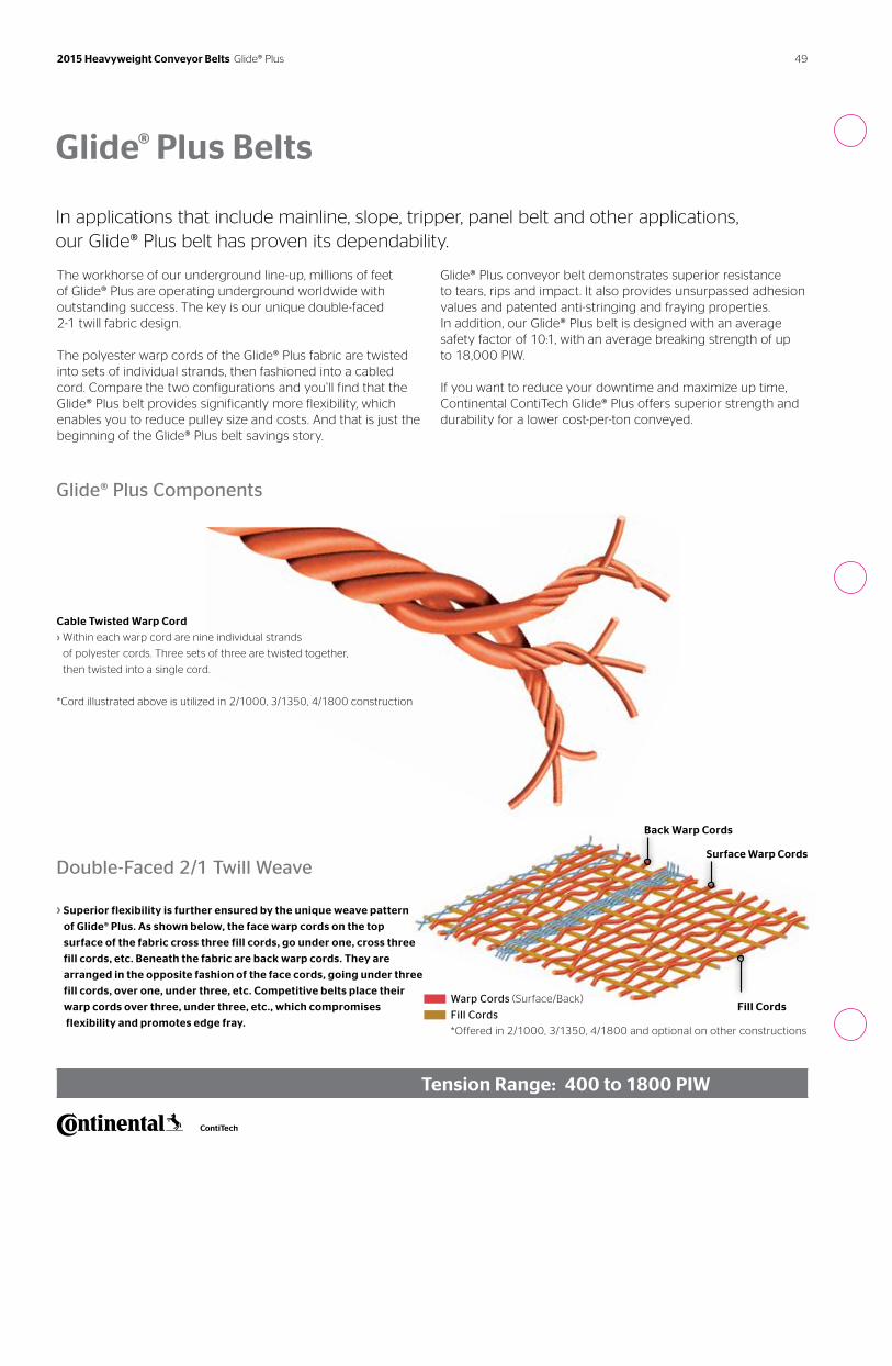
49 2015 Heavyweight Conveyor Belts Glide® Plus
Glide® Plus Belts
In applications that include mainline, slope, tripper, panel belt and other applications, our Glide® Plus belt has proven its dependability.
Glide® Plus Components
Double-Faced 2/1 Twill Weave
› Superior flexibility is further ensured by the unique weave pattern
of Glide® Plus. As shown below, the face warp cords on the top
surface of the fabric cross three fill cords, go under one, cross three
fill cords, etc. Beneath the fabric are back warp cords. They are
arranged in the opposite fashion of the face cords, going under three
fill cords, over one, under three, etc. Competitive belts place their
warp cords over three, under three, etc., which compromises
flexibility and promotes edge fray.
Tension Range: 400 to 1800 PIW
The workhorse of our underground line-up, millions of feet of Glide® Plus are operating underground worldwide with outstanding success. The key is our unique double-faced 2-1 twill fabric design.
The polyester warp cords of the Glide® Plus fabric are twisted into sets of individual strands, then fashioned into a cabled cord. Compare the two configurations and you’ll find that theGlide® Plus belt provides significantly more flexibility, which enables you to reduce pulley size and costs. And that is just thebeginning of the Glide® Plus belt savings story.
Glide® Plus conveyor belt demonstrates superior resistance to tears, rips and impact. It also provides unsurpassed adhesion values and patented anti-stringing and fraying properties. In addition, our Glide® Plus belt is designed with an average safety factor of 10:1, with an average breaking strength of up to 18,000 PIW.
If you want to reduce your downtime and maximize up time, Continental ContiTech Glide® Plus offers superior strength and durability for a lower cost-per-ton conveyed.
Fill Cords
Back Warp Cords
Surface Warp Cords
Cable Twisted Warp Cord
› Within each warp cord are nine individual strands
of polyester cords. Three sets of three are twisted together,
then twisted into a single cord.
*Cord illustrated above is utilized in 2/1000, 3/1350, 4/1800 construction
Warp Cords (Surface/Back)
Fill Cords
*Offered in 2/1000, 3/1350, 4/1800 and optional on other constructions
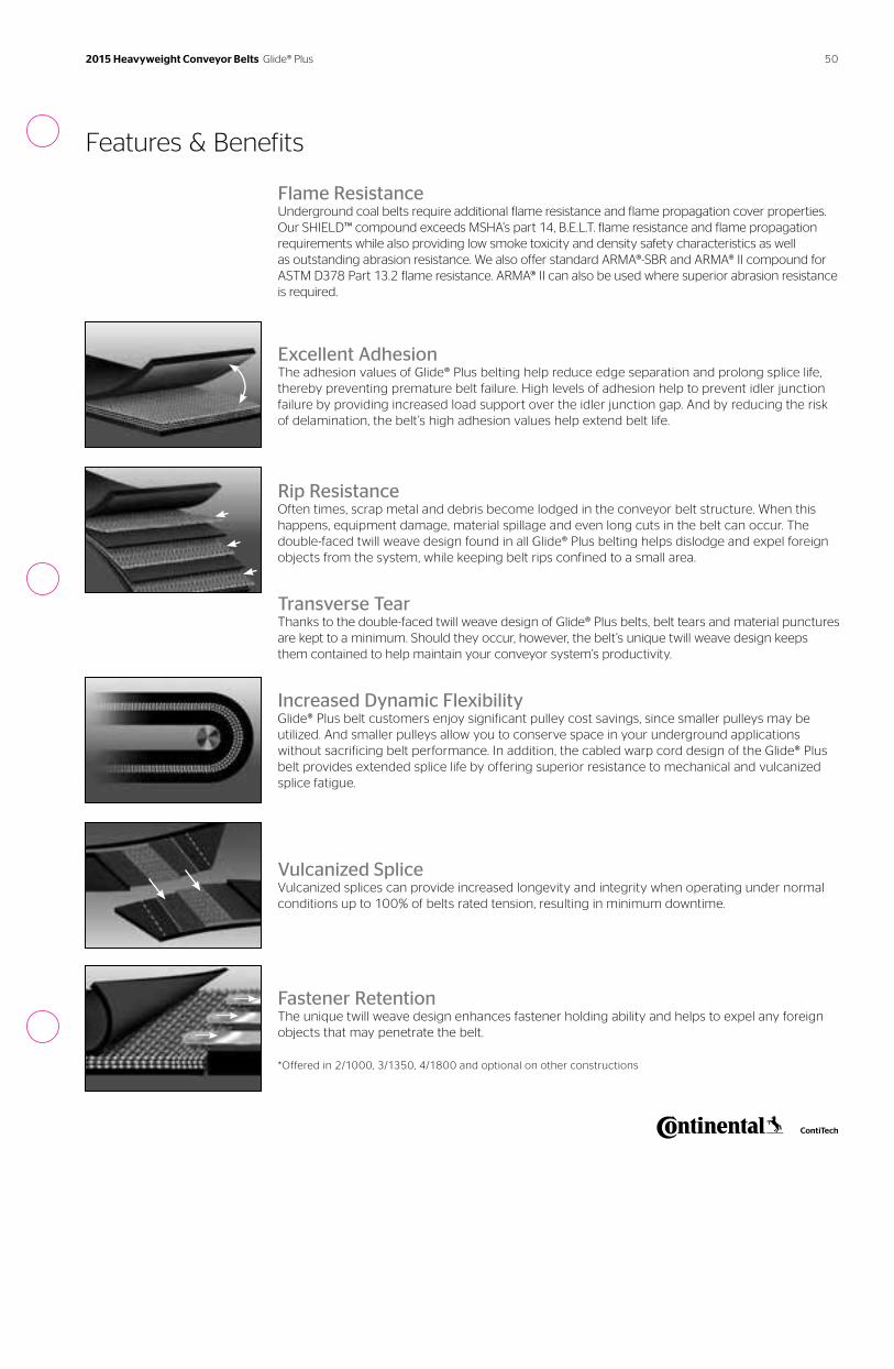
Features & Benefits
Flame ResistanceUnderground coal belts require additional flame resistance and flame propagation cover properties. Our SHIELD™ compound exceeds MSHA’s part 14, B.E.L.T. flame resistance and flame propagation requirements while also providing low smoke toxicity and density safety characteristics as well as outstanding abrasion resistance. We also offer standard ARMA®-SBR and ARMA® II compound for ASTM D378 Part 13.2 flame resistance. ARMA® II can also be used where superior abrasion resistance is required.
Excellent AdhesionThe adhesion values of Glide® Plus belting help reduce edge separation and prolong splice life, thereby preventing premature belt failure. High levels of adhesion help to prevent idler junction failure by providing increased load support over the idler junction gap. And by reducing the risk of delamination, the belt’s high adhesion values help extend belt life.
Rip ResistanceOften times, scrap metal and debris become lodged in the conveyor belt structure. When this happens, equipment damage, material spillage and even long cuts in the belt can occur. The double-faced twill weave design found in all Glide® Plus belting helps dislodge and expel foreign objects from the system, while keeping belt rips confined to a small area.
Transverse TearThanks to the double-faced twill weave design of Glide® Plus belts, belt tears and material punctures are kept to a minimum. Should they occur, however, the belt’s unique twill weave design keeps them contained to help maintain your conveyor system’s productivity.
Increased Dynamic FlexibilityGlide® Plus belt customers enjoy significant pulley cost savings, since smaller pulleys may be utilized. And smaller pulleys allow you to conserve space in your underground applications without sacrificing belt performance. In addition, the cabled warp cord design of the Glide® Plus belt provides extended splice life by offering superior resistance to mechanical and vulcanized splice fatigue.
Vulcanized SpliceVulcanized splices can provide increased longevity and integrity when operating under normal conditions up to 100% of belts rated tension, resulting in minimum downtime.
Fastener RetentionThe unique twill weave design enhances fastener holding ability and helps to expel any foreign objects that may penetrate the belt.
*Offered in 2/1000, 3/1350, 4/1800 and optional on other constructions
50 2015 Heavyweight Conveyor Belts Glide® Plus
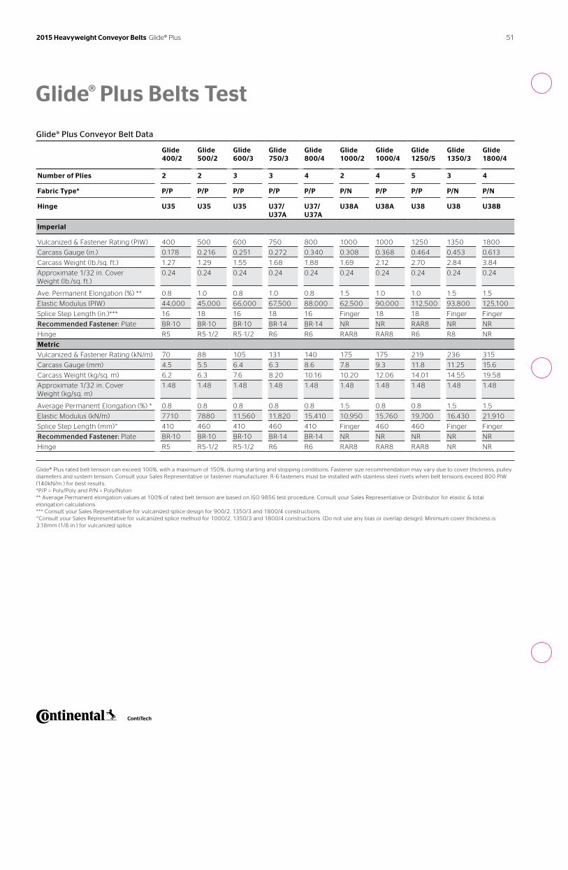
Glide® Plus Belts Test
Glide® Plus Conveyor Belt Data
Glide 400/2
Glide 500/2
Glide 600/3
Glide 750/3
Glide 800/4
Glide 1000/2
Glide 1000/4
Glide 1250/5
Glide 1350/3
Glide 1800/4
Number of Plies 2 2 3 3 4 2 4 5 3 4
Fabric Type* P/P P/P P/P P/P P/P P/N P/P P/P P/N P/N
Hinge U35 U35 U35 U37/U37A
U37/U37A
U38A U38A U38 U38 U38B
Imperial
Vulcanized & Fastener Rating (PIW) 400 500 600 750 800 1000 1000 1250 1350 1800
Carcass Gauge (in.) 0.178 0.216 0.251 0.272 0.340 0.308 0.368 0.464 0.453 0.613
Carcass Weight (lb./sq. ft.) 1.27 1.29 1.55 1.68 1.88 1.69 2.12 2.70 2.84 3.84
Approximate 1/32 in. Cover Weight (lb./sq. ft.)
0.24 0.24 0.24 0.24 0.24 0.24 0.24 0.24 0.24 0.24
Ave. Permanent Elongation (%) ** 0.8 1.0 0.8 1.0 0.8 1.5 1.0 1.0 1.5 1.5
Elastic Modulus (PIW) 44,000 45,000 66,000 67,500 88,000 62,500 90,000 112,500 93,800 125,100
Splice Step Length (in.)*** 16 18 16 18 16 Finger 18 18 Finger Finger
Recommended Fastener: Plate BR-10 BR-10 BR-10 BR-14 BR-14 NR NR RAR8 NR NR
Hinge R5 R5-1/2 R5-1/2 R6 R6 RAR8 RAR8 R6 R8 NR
Metric
Vulcanized & Fastener Rating (kN/m) 70 88 105 131 140 175 175 219 236 315
Carcass Gauge (mm) 4.5 5.5 6.4 6.3 8.6 7.8 9.3 11.8 11.25 15.6
Carcass Weight (kg/sq. m) 6.2 6.3 7.6 8.20 10.16 10.20 12.06 14.01 14.55 19.58
Approximate 1/32 in. Cover Weight (kg/sq. m)
1.48 1.48 1.48 1.48 1.48 1.48 1.48 1.48 1.48 1.48
Average Permanent Elongation (%) * 0.8 0.8 0.8 0.8 0.8 1.5 0.8 0.8 1.5 1.5
Elastic Modulus (kN/m) 7710 7880 11,560 11,820 15,410 10,950 15,760 19,700 16,430 21,910
Splice Step Length (mm)^ 410 460 410 460 410 Finger 460 460 Finger Finger
Recommended Fastener: Plate BR-10 BR-10 BR-10 BR-14 BR-14 NR NR NR NR NR
Hinge R5 R5-1/2 R5-1/2 R6 R6 RAR8 RAR8 RAR8 NR NR
Glide® Plus rated belt tension can exceed 100%, with a maximum of 150%, during starting and stopping conditions. Fastener size recommendation may vary due to cover thickness, pulley diameters and system tension. Consult your Sales Representative or fastener manufacturer. R-6 fasteners must be installed with stainless steel rivets when belt tensions exceed 800 PIW (140kN/m ) for best results. *P/P = Poly/Poly and P/N = Poly/Nylon ** Average Permanent elongation values at 100% of rated belt tension are based on ISO 9856 test procedure. Consult your Sales Representative or Distributor for elastic & total elongation calculations. *** Consult your Sales Representative for vulcanized splice design for 900/2, 1350/3 and 1800/4 constructions. ^Consult your Sales Representative for vulcanized splice method for 1000/2, 1350/3 and 1800/4 constructions. (Do not use any bias or overlap design). Minimum cover thickness is 3.18mm (1/8 in.) for vulcanized splice.
51 2015 Heavyweight Conveyor Belts Glide® Plus
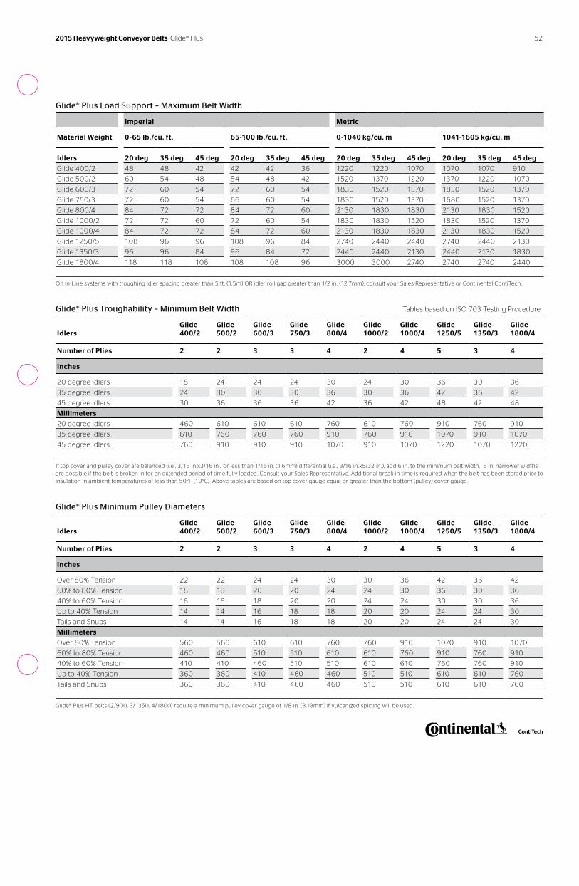
Glide® Plus Load Support – Maximum Belt Width
Imperial Metric
Material Weight 0-65 lb./cu. ft. 65-100 lb./cu. ft. 0-1040 kg/cu. m 1041-1605 kg/cu. m
Idlers 20 deg 35 deg 45 deg 20 deg 35 deg 45 deg 20 deg 35 deg 45 deg 20 deg 35 deg 45 deg
Glide 400/2 48 48 42 42 42 36 1220 1220 1070 1070 1070 910
Glide 500/2 60 54 48 54 48 42 1520 1370 1220 1370 1220 1070
Glide 600/3 72 60 54 72 60 54 1830 1520 1370 1830 1520 1370
Glide 750/3 72 60 54 66 60 54 1830 1520 1370 1680 1520 1370
Glide 800/4 84 72 72 84 72 60 2130 1830 1830 2130 1830 1520
Glide 1000/2 72 72 60 72 60 54 1830 1830 1520 1830 1520 1370
Glide 1000/4 84 72 72 84 72 60 2130 1830 1830 2130 1830 1520
Glide 1250/5 108 96 96 108 96 84 2740 2440 2440 2740 2440 2130
Glide 1350/3 96 96 84 96 84 72 2440 2440 2130 2440 2130 1830
Glide 1800/4 118 118 108 108 108 96 3000 3000 2740 2740 2740 2440
On In-Line systems with troughing idler spacing greater than 5 ft. (1.5m) OR idler roll gap greater than 1/2 in. (12.7mm), consult your Sales Representative or Continental ContiTech.
Glide® Plus Troughability – Minimum Belt Width Tables based on ISO 703 Testing Procedure
Idlers
Glide 400/2
Glide 500/2
Glide 600/3
Glide 750/3
Glide 800/4
Glide 1000/2
Glide 1000/4
Glide 1250/5
Glide 1350/3
Glide 1800/4
Number of Plies 2 2 3 3 4 2 4 5 3 4
Inches
20 degree idlers 18 24 24 24 30 24 30 36 30 36
35 degree idlers 24 30 30 30 36 30 36 42 36 42
45 degree idlers 30 36 36 36 42 36 42 48 42 48
Millimeters
20 degree idlers 460 610 610 610 760 610 760 910 760 910
35 degree idlers 610 760 760 760 910 760 910 1070 910 1070
45 degree idlers 760 910 910 910 1070 910 1070 1220 1070 1220
If top cover and pulley cover are balanced (i.e. , 3/16 in.x3/16 in.) or less than 1/16 in. (1.6mm) differential (i.e. , 3/16 in.x5/32 in.), add 6 in. to the minimum belt width. 6 in. narrower widths are possible if the belt is broken in for an extended period of time fully loaded. Consult your Sales Representative. Additional break-in time is required when the belt has been stored prior to insulation in ambient temperatures of less than 50°F (10°C). Above tables are based on top cover gauge equal or greater than the bottom (pulley) cover gauge.
Glide® Plus Minimum Pulley Diameters
Idlers
Glide 400/2
Glide 500/2
Glide 600/3
Glide 750/3
Glide 800/4
Glide 1000/2
Glide 1000/4
Glide 1250/5
Glide 1350/3
Glide 1800/4
Number of Plies 2 2 3 3 4 2 4 5 3 4
Inches
Over 80% Tension 22 22 24 24 30 30 36 42 36 42
60% to 80% Tension 18 18 20 20 24 24 30 36 30 36
40% to 60% Tension 16 16 18 20 20 24 24 30 30 36
Up to 40% Tension 14 14 16 18 18 20 20 24 24 30
Tails and Snubs 14 14 16 18 18 20 20 24 24 30
Millimeters
Over 80% Tension 560 560 610 610 760 760 910 1070 910 1070
60% to 80% Tension 460 460 510 510 610 610 760 910 760 910
40% to 60% Tension 410 410 460 510 510 610 610 760 760 910
Up to 40% Tension 360 360 410 460 460 510 510 610 610 760
Tails and Snubs 360 360 410 460 460 510 510 610 610 760
Glide® Plus HT belts (2/900, 3/1350, 4/1800) require a minimum pulley cover gauge of 1/8 in. (3.18mm) if vulcanized splicing will be used.
52 2015 Heavyweight Conveyor Belts Glide® Plus
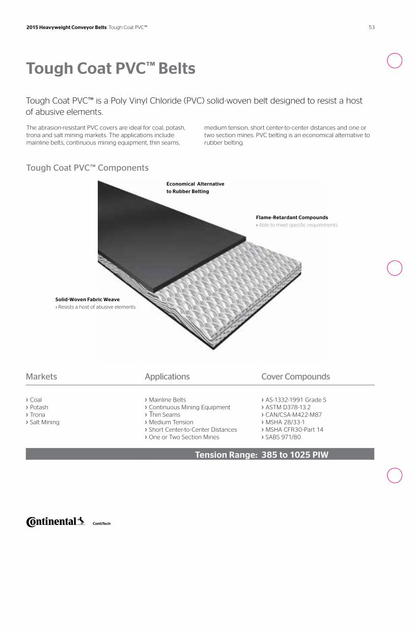
53 2015 Heavyweight Conveyor Belts Tough Coat PVC™
Tough Coat PVC™ Belts
Tough Coat PVC™ is a Poly Vinyl Chloride (PVC) solid-woven belt designed to resist a host of abusive elements.
The abrasion-resistant PVC covers are ideal for coal, potash, trona and salt mining markets. The applications include: mainline belts, continuous mining equipment, thin seams,
medium tension, short center-to-center distances and one or two section mines. PVC belting is an economical alternative to rubber belting.
Solid-Woven Fabric Weave
› Resists a host of abusive elements
Economical Alternative
to Rubber Belting
Tough Coat PVC™ Components
Markets Applications Cover Compounds
› Coal› Potash› Trona› Salt Mining
› Mainline Belts› Continuous Mining Equipment› Thin Seams› Medium Tension› Short Center-to-Center Distances › One or Two Section Mines
› AS-1332-1991 Grade S › ASTM D378-13.2› CAN/CSA-M422-M87› MSHA 28/33-1› MSHA CFR30-Part 14› SABS 971/80
Tension Range: 385 to 1025 PIW
Flame-Retardant Compounds
› Able to meet specific requirements
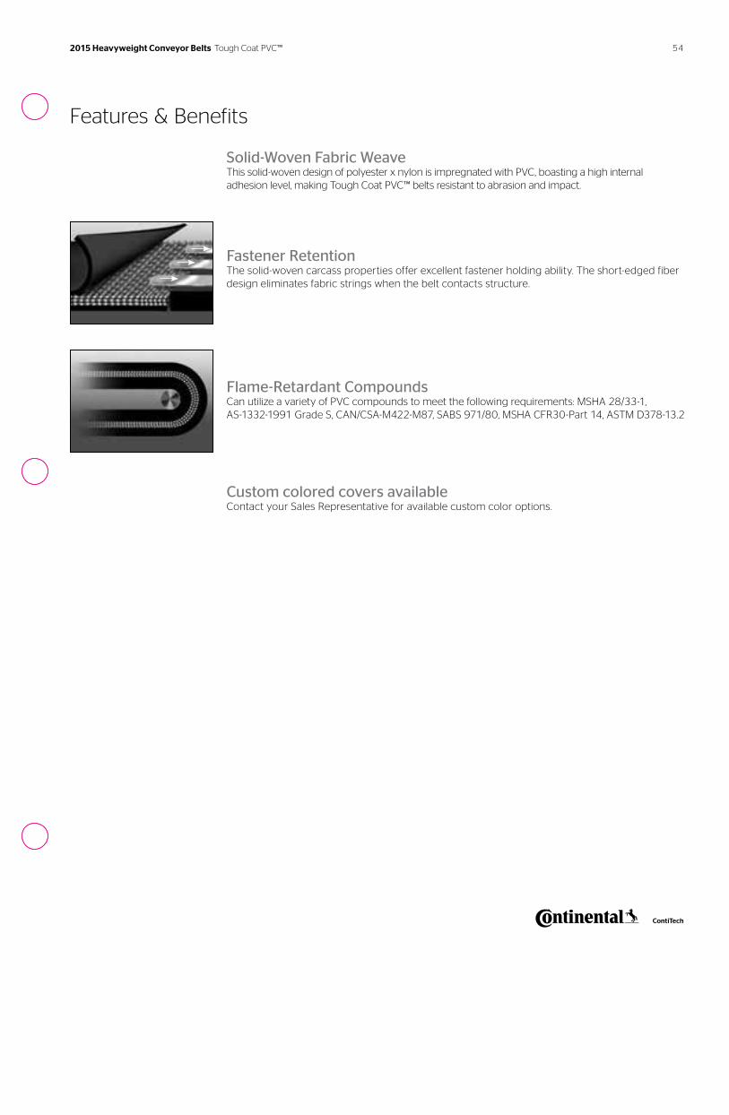
54
Features & Benefits
Solid-Woven Fabric WeaveThis solid-woven design of polyester x nylon is impregnated with PVC, boasting a high internal adhesion level, making Tough Coat PVC™ belts resistant to abrasion and impact.
Fastener RetentionThe solid-woven carcass properties offer excellent fastener holding ability. The short-edged fiber design eliminates fabric strings when the belt contacts structure.
Flame-Retardant CompoundsCan utilize a variety of PVC compounds to meet the following requirements: MSHA 28/33-1, AS-1332-1991 Grade S, CAN/CSA-M422-M87, SABS 971/80, MSHA CFR30-Part 14, ASTM D378-13.2
Custom colored covers availableContact your Sales Representative for available custom color options.
2015 Heavyweight Conveyor Belts Tough Coat PVC™
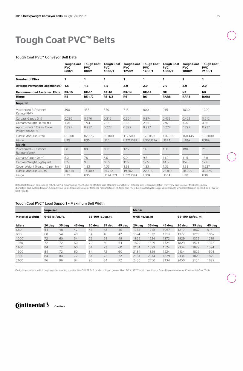
55
Tough Coat PVC™ Belts
Tough Coat PVC™ Conveyor Belt Data
Tough Coat PVC 680/1
Tough Coat PVC 800/1
Tough Coat PVC 1000/1
Tough Coat PVC 1250/1
Tough Coat PVC 1400/1
Tough Coat PVC 1600/1
Tough Coat PVC 1800/1
Tough Coat PVC 2100/1
Number of Plies 1 1 1 1 1 1 1 1
Average Permanent Elogation (%) 1.5 1.5 1.5 2.0 2.0 2.0 2.0 2.0
Recommended Fastener: Plate BR-10 BR-10 BR-10 BR-14 BR-14 NR NR NR
Hinge R5 R5-1/2 R5-1/2 R6 R6 RAR8 RAR8 RAR8
Imperial
Vulcanized & Fastener Rating (PIW)
390 455 570 715 800 915 1030 1200
Carcass Gauge (in.) 0.236 0.276 0.315 0.354 0.374 0.433 0.452 0.512
Carcass Weight (lb./sq. ft.) 1.76 1.94 2.15 2.35 2.56 2.97 3.07 3.56
Approximate 1/32 in. Cover Weight (lb./sq. ft.)
0.227 0.227 0.227 0.227 0.227 0.227 0.227 0.227
Elastic Modulus (PIW) 61,200 82,275 90,000 112,500 126,850 136,000 160,445 190,000
Hinge U35 U35 U35 U37/U37A U35/U37A U38A U38A U38A
Metric
Vulcanized & Fastener Rating (kN/m)
68 80 100 125 140 160 180 210
Carcass Gauge (mm) 6.0 7.0 8.0 9.0 9.5 11.0 11.5 13.0
Carcass Weight (kg/sq. m) 8.6 9.5 10.5 11.5 12.5 14.5 15.0 17.4
Cover Weight (kg/sq. m) per 1mm 1.33 1.33 1.33 1.33 1.33 1.33 1.33 0.227
Elastic Modulus (kN/m) 10,718 14,409 15,762 19,702 22,215 23,818 28,099 33,275
Hinge U35 U35 U37/U37A U37/U37A U38A U38A U38 U38
Rated belt tension can exceed 100%, with a maximum of 150%, during starting and stopping conditions. Fastener size recommendation may vary due to cover thickness, pulley diameters and system tension. Consult your Sales Representative or fastener manufacturer. R6 fasteners must be installed with stainless steel rivets when belt tension exceed 800 PIW for best results.
2015 Heavyweight Conveyor Belts Tough Coat PVC™
Tough Coat PVC™ Load Support – Maximum Belt Width
Imperial Metric
Material Weight 0-65 lb./cu. ft. 65-100 lb./cu. ft. 0-65 kg/cu. m 65-100 kg/cu. m
Idlers 20 deg 35 deg 45 deg 20 deg 35 deg 45 deg 20 deg 35 deg 45 deg 20 deg 35 deg 45 deg
680 54 48 42 48 42 36 1372 1219 1067 1219 1067 914
800 60 54 48 54 48 42 1524 1372 1219 1372 1219 1067
1000 72 60 54 72 54 48 1829 1524 1372 1829 1372 1219
1250 72 72 60 72 60 54 1829 1829 1524 1829 1524 1372
1400 84 72 60 84 72 60 2134 1829 1524 2134 1829 1524
1600 84 72 60 84 72 60 2134 1829 1524 2134 1829 1524
1800 84 84 72 84 72 72 2134 2134 1829 2134 1829 1829
2100 96 96 84 96 84 72 2450 2450 2134 2450 2134 1829
On In-Line systems with troughing idler spacing greater than 5 ft. (1.5m) or idler roll gap greater than 1/2 in. (12.7mm), consult your Sales Representative or Continental ContiTech.
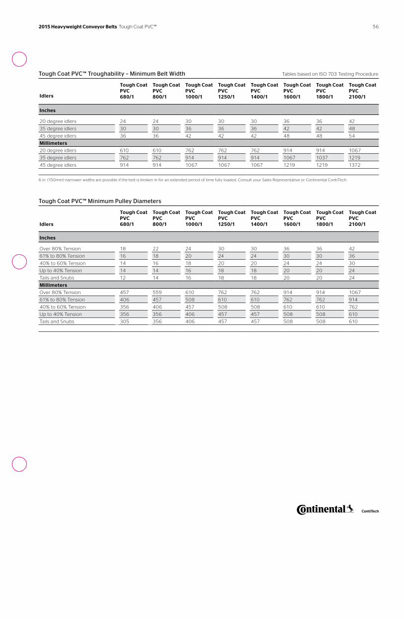
56
Tough Coat PVC™ Troughability – Minimum Belt Width Tables based on ISO 703 Testing Procedure
Idlers
Tough Coat PVC 680/1
Tough Coat PVC 800/1
Tough Coat PVC 1000/1
Tough Coat PVC 1250/1
Tough Coat PVC 1400/1
Tough Coat PVC 1600/1
Tough Coat PVC 1800/1
Tough Coat PVC 2100/1
Inches
20 degree idlers 24 24 30 30 30 36 36 42
35 degree idlers 30 30 36 36 36 42 42 48
45 degree idlers 36 36 42 42 42 48 48 54
Millimeters
20 degree idlers 610 610 762 762 762 914 914 1067
35 degree idlers 762 762 914 914 914 1067 1037 1219
45 degree idlers 914 914 1067 1067 1067 1219 1219 1372
6 in. (150mm) narrower widths are possible if the belt is broken in for an extended period of time fully loaded. Consult your Sales Representative or Continental ContiTech.
Tough Coat PVC™ Minimum Pulley Diameters
Idlers
Tough Coat PVC 680/1
Tough Coat PVC 800/1
Tough Coat PVC 1000/1
Tough Coat PVC 1250/1
Tough Coat PVC 1400/1
Tough Coat PVC 1600/1
Tough Coat PVC 1800/1
Tough Coat PVC 2100/1
Inches
Over 80% Tension 18 22 24 30 30 36 36 42
61% to 80% Tension 16 18 20 24 24 30 30 36
40% to 60% Tension 14 16 18 20 20 24 24 30
Up to 40% Tension 14 14 16 18 18 20 20 24
Tails and Snubs 12 14 16 18 18 20 20 24
Millimeters
Over 80% Tension 457 559 610 762 762 914 914 1067
61% to 80% Tension 406 457 508 610 610 762 762 914
40% to 60% Tension 356 406 457 508 508 610 610 762
Up to 40% Tension 356 356 406 457 457 508 508 610
Tails and Snubs 305 356 406 457 457 508 508 610
2015 Heavyweight Conveyor Belts Tough Coat PVC™
2015 Heavyweight Conveyor Belts Flexsteel®
Top Cover
› Protects steel cords
› Various compounds available
Bottom Cover
› Protects steel cords
› Various compounds
available
› Low energy
options available
Steel Cord
› Provides superior bonding to covers
and insulation gum
› Allows high flexibility and low elongation
› Galvanized to provide barrier against corrosion
Insulation Gum
› Penetrates and adheres to steel cords
› Provides superior corrosion resistance
› Provides improved splice efficiency
Conveyor Belt Components
the cover rubbers. Top and bottom covers provide maximum protection to the steel cord. The cover compounds are specifically designed to meet the demands of the application and are available in a wide variety of rubber types and gauges.
Flexsteel® Belts’ steel cord provides superior impact resistance, with the number and size being selected to meet the desired operating tension and application needs. The insulation gum is specifically designed to encapsulate each steel cord filament to reduce internal friction while providing enhanced adhesion to
Flexsteel® Belts
Continental ContiTech Flexsteel® belts are custom designed to meet the specific needs of the given application, providing superior protection against the abuse of conveying virtually any material.
Flexsteel® Stacker® ST3500/48 3/4 in. x 1/4 in.
Belt Construction
BeltWidth
Belt breaking strength
(in kilonewtons per meter width)
Top Cover Gauge
Bottom or Pulley Cover Gauge
Rubber Compound
Belt Construction Nomenclature Example
58 2015 Heavyweight Conveyor Belts Flexsteel® Belt Construction
Markets Applications Cover Compounds
› Aggregate› Cement› Coal› Hard Rock› Power Generation› Steel Production
› Mainlines› Overland Belts› Pit Belts› Ship Loaders› Slope Belts› Any High Abuse Applications
› 6740A› ARMA® II› ARMA® ORSC› ARMA®-SBR› Compound P› Easyrider™› FRAS-C› Global X®› Solar-Shield®› Stacker®› Style BLE› Style B II› Survivor®› Survivor® Plus› Other compounds available on request
See the process diagram for Aggregate, Hard Rock Mining, Sand and Gravel markets on page 6 for alternative belt recommendations.
Get a lower cost-per-ton conveyed. Tension Range: ST 500 to over ST 10,000
Flexsteel® Belts
Since we introduced the world’s first steel reinforced belt to the material handling industry in 1942, we have continued to advance the technology to satisfy the most demanding and abusive conveyor applications.
Using state-of-the-art technology, we ensure superior product design and maximum performance for our customers. Shipping from six production plants on five continents, Flexsteel® remains our premium global product.
Our worldwide engineering group continues to design Flexsteel® specifications that will provide a lower cost-per-ton of material conveyed for each customer’s unique system.
59 2015 Heavyweight Conveyor Belts Flexsteel®
Flexsteel® Belts A Technically Superior Product
Generations of our engineers have been involved for over 70 years in the design and application of Flexsteel® conveyor belting. This cumulative experience translates into state-of-the-art technology, assuring superior product design and maximum performance for our customers.
Superior strength, durability, ease of installation
Continental ContiTech's Flexsteel® conveyor belting has provided maximum protection against pounding and abuse in some of the world's largest and most demanding applications. Flexsteel® belting is the only choice when extremely high tensions are present, having proven itself on copper and oil sands system operations at 6000 PIW (ST7000) tension.
Flexsteel® is also the preferred belt on long overlands and short Stacker systems where minimum belt elongation is a critical design consideration. Flexsteel®’s steel cord reinforcement elongates a maximum of .25% at rated tension, allowing for acceptable take-up travel design on long overlands, as well as short Stacker/Reclaimer systems.
We have the capability to manufacture Flexsteel® belts in long lengths up to 168 in. (4.2m) roll diameters, or 50 short ton (45.4 M.T.) rolls at some production locations. This allows for the minimum number of splices or joints in a conveyor system, which facilitates faster installation while providing a more reliable system. Specialized oblong packaging is available to further maximize belt lengths.
Additional time can be saved during installation by using another Flexsteel® innovation, Preform™ Splice kits. Preform™ is a pre-grooved form that simplifies splicing by allowing you to “sandwhich” the cables coming from either side between the formed rubber. Not only is the process of splicing made easier, but the belt itself is made stronger.
You can depend on Flexsteel® steel cord belts to be precisely engineered to meet rigorous manufacturing standards. Rely on Flexsteel® for strength, durability and ease of installation.
There are three component parts to Flexsteel® belting, each one critical to belt performance:
Zinc galvanized steel cordFlexsteel® belts are designed by selecting cord construction to provide the best specification for a particular application. The cords, made up of many wire filaments, are constructed to provide high flexibility, low elongation and permit efficient and high strength splice designs. The galvanized zinc coating produces a bonding agent between the cord and insulation gum and provides an important barrier against corrosion.
Insulation gum (core rubber)Extensive rubber compounding technology has enabled Flexsteel® engineers to develop a superior insulation gum bonding rubber, which penetrates and adheres to the steel cords. The result is excellent adhesions, corrosion resistance and splice efficiencies.
Outer rubber coversThe advanced compounds in Flexsteel®’s top and bottom covers are designed to protect the steel cord strength member against the abusive environmental conditions prevalent in most conveying applications. Compounds are available to withstand abrasion, jagged cutting and gouging, high impact, sub-zero temperatures, moderate heat, hardening effects of ozone attack and fire propagation. Special service compounds are available for unique applications, such as the oil sands in Canada, which require a compound that withstands both low temperatures and oil.
60 2015 Heavyweight Conveyor Belts Flexsteel®
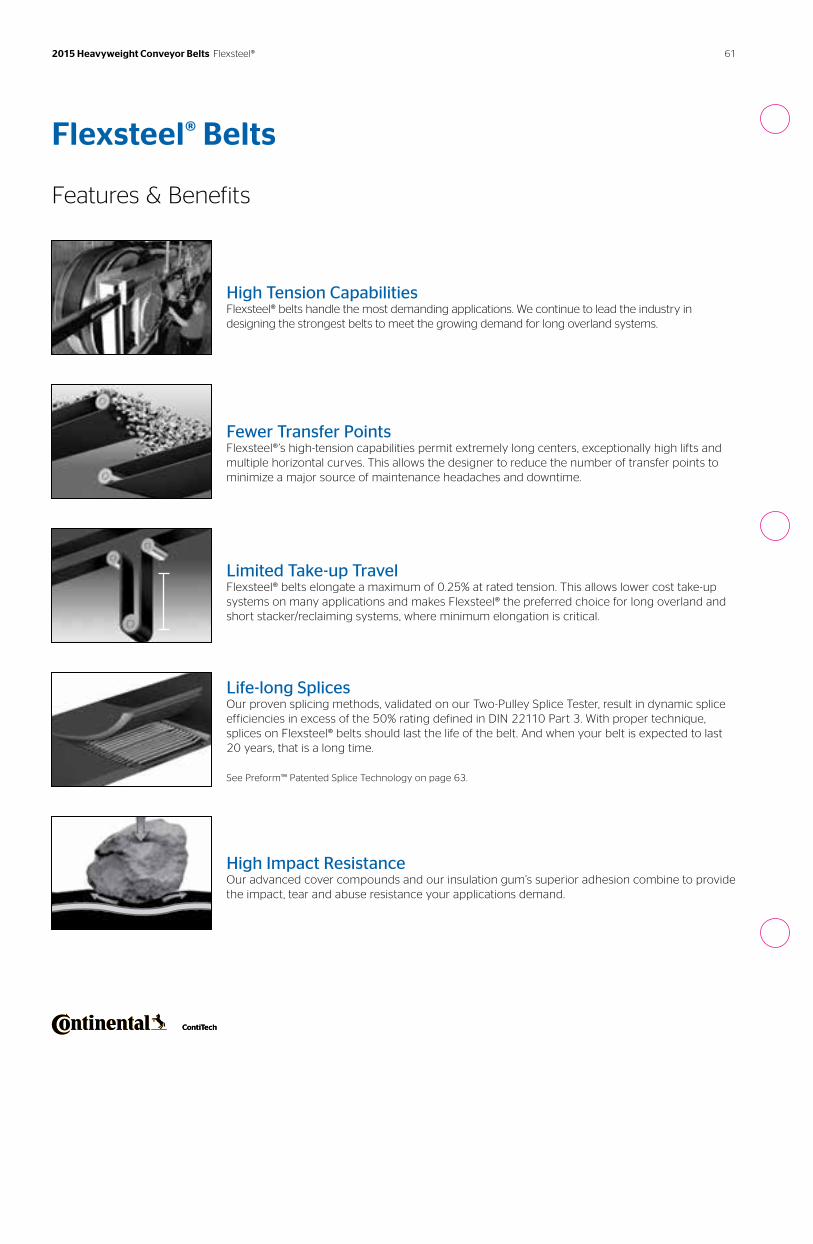
Flexsteel® Belts
Features & Benefits
High Tension CapabilitiesFlexsteel® belts handle the most demanding applications. We continue to lead the industry in designing the strongest belts to meet the growing demand for long overland systems.
Fewer Transfer PointsFlexsteel®’s high-tension capabilities permit extremely long centers, exceptionally high lifts and multiple horizontal curves. This allows the designer to reduce the number of transfer points to minimize a major source of maintenance headaches and downtime.
Limited Take-up TravelFlexsteel® belts elongate a maximum of 0.25% at rated tension. This allows lower cost take-up systems on many applications and makes Flexsteel® the preferred choice for long overland and short stacker/reclaiming systems, where minimum elongation is critical.
Life-long SplicesOur proven splicing methods, validated on our Two-Pulley Splice Tester, result in dynamic splice efficiencies in excess of the 50% rating defined in DIN 22110 Part 3. With proper technique, splices on Flexsteel® belts should last the life of the belt. And when your belt is expected to last 20 years, that is a long time.
See Preform™ Patented Splice Technology on page 63.
High Impact ResistanceOur advanced cover compounds and our insulation gum’s superior adhesion combine to provide the impact, tear and abuse resistance your applications demand.
61 2015 Heavyweight Conveyor Belts Flexsteel®
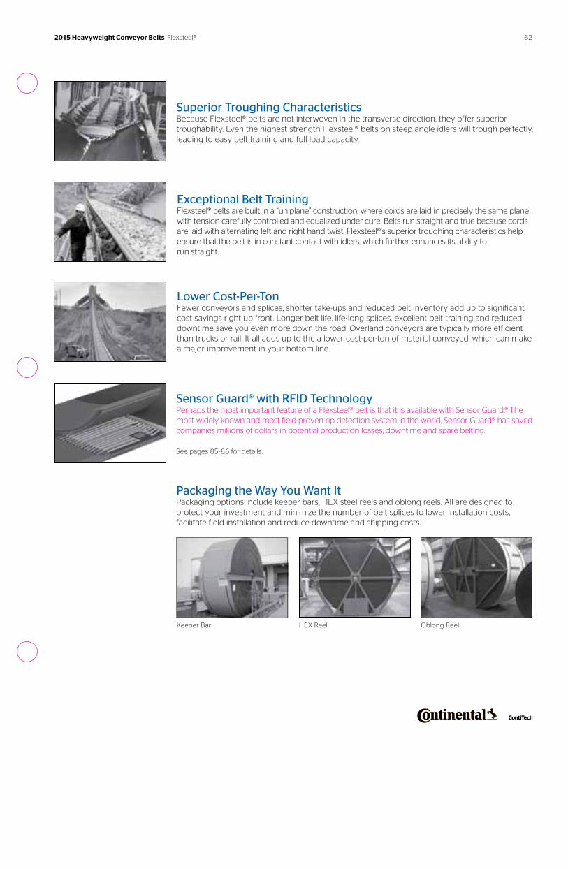
Sensor Guard® with RFID TechnologyPerhaps the most important feature of a Flexsteel® belt is that it is available with Sensor Guard.® The most widely known and most field-proven rip detection system in the world, Sensor Guard® has saved companies millions of dollars in potential production losses, downtime and spare belting.
See pages 85-86 for details.
Packaging the Way You Want ItPackaging options include keeper bars, HEX steel reels and oblong reels. All are designed to protect your investment and minimize the number of belt splices to lower installation costs, facilitate field installation and reduce downtime and shipping costs.
Keeper Bar HEX Reel Oblong Reel
Exceptional Belt TrainingFlexsteel® belts are built in a “uniplane” construction, where cords are laid in precisely the same plane with tension carefully controlled and equalized under cure. Belts run straight and true because cords are laid with alternating left and right hand twist. Flexsteel®’s superior troughing characteristics help ensure that the belt is in constant contact with idlers, which further enhances its ability to run straight.
Superior Troughing CharacteristicsBecause Flexsteel® belts are not interwoven in the transverse direction, they offer superior troughability. Even the highest strength Flexsteel® belts on steep angle idlers will trough perfectly, leading to easy belt training and full load capacity.
Lower Cost-Per-TonFewer conveyors and splices, shorter take-ups and reduced belt inventory add up to significant cost savings right up front. Longer belt life, life-long splices, excellent belt training and reduced downtime save you even more down the road. Overland conveyors are typically more efficient than trucks or rail. It all adds up to the a lower cost-per-ton of material conveyed, which can make a major improvement in your bottom line.
62 2015 Heavyweight Conveyor Belts Flexsteel®
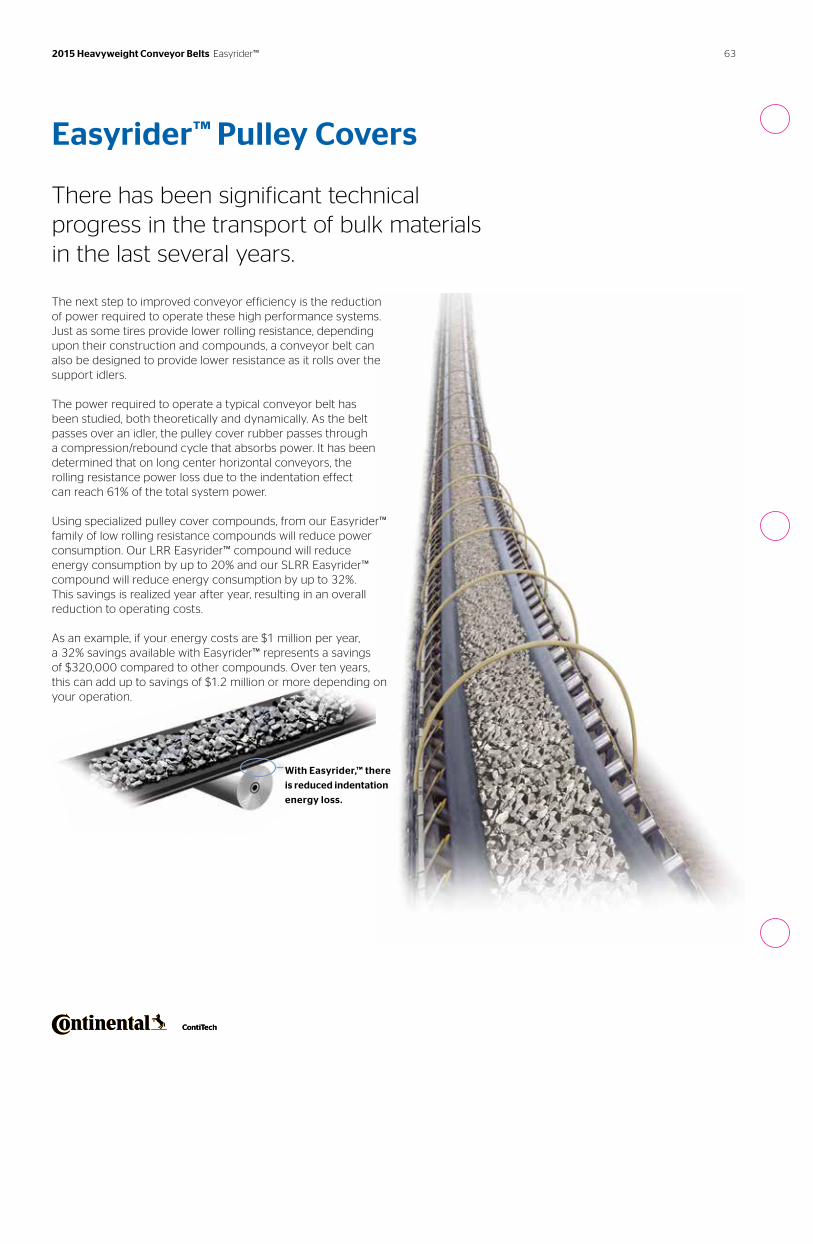
Easyrider™ Pulley Covers There has been significant technical progress in the transport of bulk materials in the last several years.
The next step to improved conveyor efficiency is the reduction of power required to operate these high performance systems. Just as some tires provide lower rolling resistance, depending upon their construction and compounds, a conveyor belt can also be designed to provide lower resistance as it rolls over the support idlers.
The power required to operate a typical conveyor belt has been studied, both theoretically and dynamically. As the belt passes over an idler, the pulley cover rubber passes through a compression/rebound cycle that absorbs power. It has been determined that on long center horizontal conveyors, the rolling resistance power loss due to the indentation effect can reach 61% of the total system power.
Using specialized pulley cover compounds, from our Easyrider™ family of low rolling resistance compounds will reduce power consumption. Our LRR Easyrider™ compound will reduce energy consumption by up to 20% and our SLRR Easyrider™ compound will reduce energy consumption by up to 32%. This savings is realized year after year, resulting in an overall reduction to operating costs.
As an example, if your energy costs are $1 million per year, a 32% savings available with Easyrider™ represents a savings of $320,000 compared to other compounds. Over ten years, this can add up to savings of $1.2 million or more depending on your operation.
With Easyrider,™ there
is reduced indentation
energy loss.
63 2015 Heavyweight Conveyor Belts Easyrider™
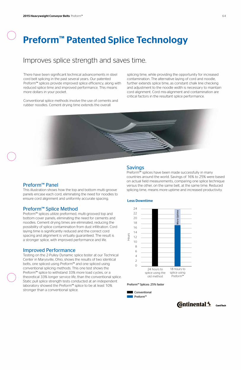
There have been significant technical advancements in steel cord belt splicing in the past several years. Our patented Preform™ splices provide improved splice efficiency, along with reduced splice time and improved performance. This means more dollars in your pocket.
Conventional splice methods involve the use of cements and rubber noodles. Cement drying time extends the overall
splicing time, while providing the opportunity for increased contamination. The alternative laying of cord and noodle, further extends splice time, as constant chalk line checking and adjustment to the noodle width is necessary to maintain cord alignment. Cord mis-alignment and contamination are critical factors in the resultant splice performance.
Preform™ Patented Splice Technology
Improves splice strength and saves time.
Preform™ PanelThis illustration shows how the top and bottom multi-groove panels encase each cord, eliminating the need for noodles to ensure cord alignment and uniformly accurate spacing.
Preform™ Splice MethodPreform™ splices utilize preformed, multi-grooved top and bottom cover panels, eliminating the need for cements and noodles. Cement drying times are eliminated, reducing the possibility of splice contamination from dust infiltration. Cord laying time is significantly reduced and the correct cord spacing and alignment is virtually guaranteed. The result is a stronger splice, with improved performance and life.
Improved PerformanceTesting on the 2-Pulley Dynamic splice tester at our Technical Center in Marysville, Ohio, shows the results of two identical belts, one spliced using Preform™ and one spliced using conventional splicing methods. This one test shows the Preform™ splice to withstand 33% more load cycles, or a theoretical 33% longer service life, than the conventional splice. Static pull splice strength tests conducted at an independent laboratory showed the Preform™ splice to be at least 10% stronger than a conventional splice.
SavingsPreform™ splices have been made successfully in many countries around the world. Savings of 16% to 25% were based on actual field measurements, comparing one splice technique versus the other, on the same belt, at the same time. Reduced splicing time, means more uptime and increased productivity.
24 hours to splice using the
old method
18 hours tosplice using
Preform™
24
22
20
18
16
14
12
10
8
6
4
2
0
Ho
urs
Less Downtime
Preform™ Splices: 25% faster
Conventional
Preform™
Mo
re U
pti
me
64 2015 Heavyweight Conveyor Belts Preform™
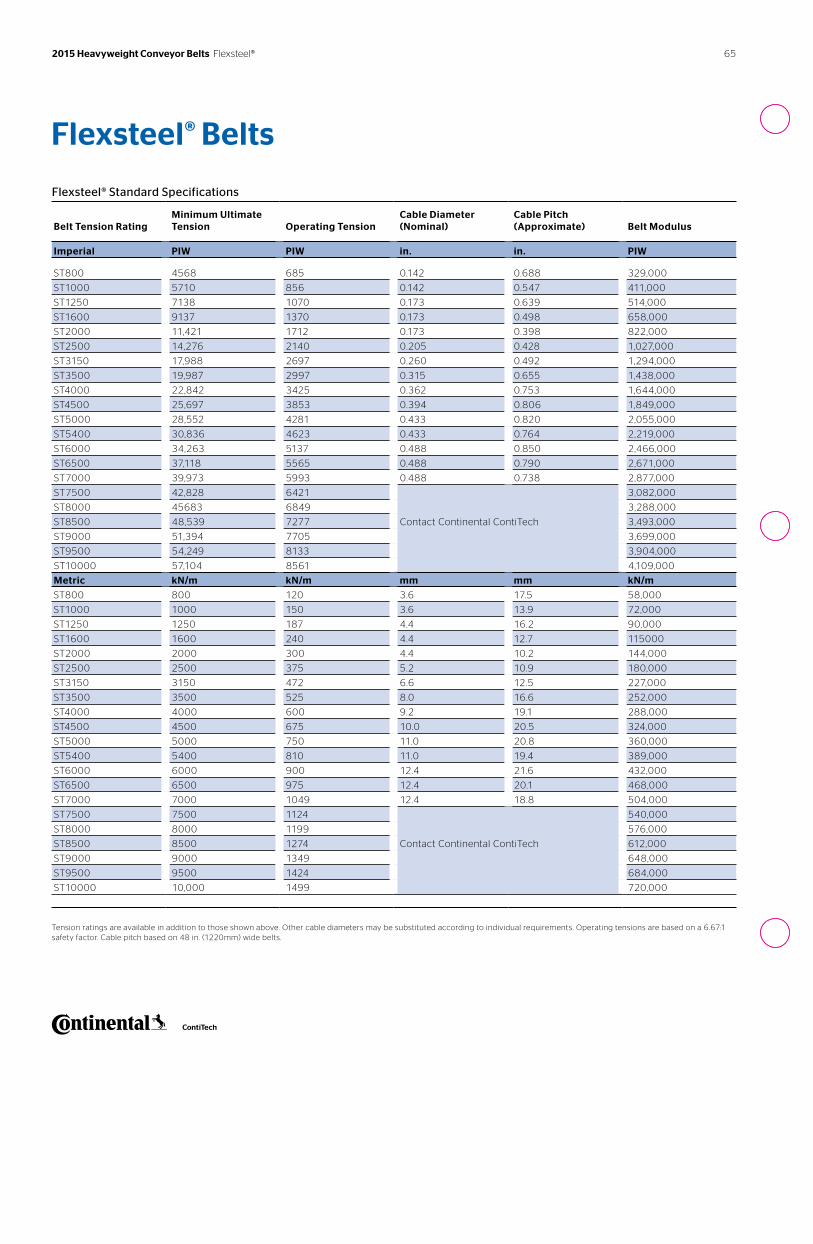
65 2015 Heavyweight Conveyor Belts Flexsteel®
Flexsteel® Standard Specifications
Belt Tension Rating
Minimum Ultimate Tension
Operating Tension
Cable Diameter (Nominal)
Cable Pitch (Approximate)
Belt Modulus
Imperial PIW PIW in. in. PIW
ST800 4568 685 0.142 0.688 329,000
ST1000 5710 856 0.142 0.547 411,000
ST1250 7138 1070 0.173 0.639 514,000
ST1600 9137 1370 0.173 0.498 658,000
ST2000 11,421 1712 0.173 0.398 822,000
ST2500 14,276 2140 0.205 0.428 1,027,000
ST3150 17,988 2697 0.260 0.492 1,294,000
ST3500 19,987 2997 0.315 0.655 1,438,000
ST4000 22,842 3425 0.362 0.753 1,644,000
ST4500 25,697 3853 0.394 0.806 1,849,000
ST5000 28,552 4281 0.433 0.820 2,055,000
ST5400 30,836 4623 0.433 0.764 2,219,000
ST6000 34,263 5137 0.488 0.850 2,466,000
ST6500 37,118 5565 0.488 0.790 2,671,000
ST7000 39,973 5993 0.488 0.738 2,877,000
ST7500 42,828 6421
Contact Continental ContiTech
3,082,000
ST8000 45683 6849 3,288,000
ST8500 48,539 7277 3,493,000
ST9000 51,394 7705 3,699,000
ST9500 54,249 8133 3,904,000
ST10000 57,104 8561 4,109,000
Metric kN/m kN/m mm mm kN/m
ST800 800 120 3.6 17.5 58,000
ST1000 1000 150 3.6 13.9 72,000
ST1250 1250 187 4.4 16.2 90,000
ST1600 1600 240 4.4 12.7 115000
ST2000 2000 300 4.4 10.2 144,000
ST2500 2500 375 5.2 10.9 180,000
ST3150 3150 472 6.6 12.5 227,000
ST3500 3500 525 8.0 16.6 252,000
ST4000 4000 600 9.2 19.1 288,000
ST4500 4500 675 10.0 20.5 324,000
ST5000 5000 750 11.0 20.8 360,000
ST5400 5400 810 11.0 19.4 389,000
ST6000 6000 900 12.4 21.6 432,000
ST6500 6500 975 12.4 20.1 468,000
ST7000 7000 1049 12.4 18.8 504,000
ST7500 7500 1124
Contact Continental ContiTech
540,000
ST8000 8000 1199 576,000
ST8500 8500 1274 612,000
ST9000 9000 1349 648,000
ST9500 9500 1424 684,000
ST10000 10,000 1499 720,000
Tension ratings are available in addition to those shown above. Other cable diameters may be substituted according to individual requirements. Operating tensions are based on a 6.67:1 safety factor. Cable pitch based on 48 in. (1220mm) wide belts.
Flexsteel® Belts

66
Flexsteel® Belt Thickness
Imperial
Belt Tension Rating PIW 600-1000 1001-1926 1927-2251 2252-2825 2826-3200
Cable Diameter in. 0.15 0.18 0.21 0.26 0.32
Belt Tension Rating PIW 3201-3500 3501-4200 4201-4650 4651-6420
Cable Diameter in. 0.37 0.40 0.44 0.49
Metric
Belt Tension Rating kN/m ST701-ST1169 ST1170-ST2250 ST2251-ST2629 ST2630-ST3300 ST3301-ST3738
Cable Diameter mm 3.6 4.4 5.2 6.6 8.0
Belt Tension Rating kN/m ST3739-ST4089 ST4090-ST4906 ST4907-ST5432 ST5433-ST7499
Cable Diameter mm 9.2 10.0 11.0 12.4
Approximate belt thickness = cable diameter + cover gauges.
Flexsteel® Belt Weight
Imperial
Belt Tension Rating PIW 685 856 1070 1370 1712
Carcass Weight lb./sq. ft. 1.4 1.5 2.1 2.3 2.6
Belt Tension Rating PIW 2140 2697 2997 3425 3853
Carcass Weight lb./sq. ft. 2.9 4.2 4.4 5.0 5.5
Belt Tension Rating PIW 4281 4623 5137 5565 5993
Carcass Weight lb./sq. ft. 6.3 6.7 7.5 7.8 8.2
Cover Compound Stacker Style BII ARMA®-SBR Compound P
Cover Weight per 1/32 in. (lb./sq. ft.) 0.18 0.19 0.20 0.19
Metric
Belt Tension Rating kN/m ST800 ST1000 ST1250 ST1600 ST2000
Carcass Weight kg/sq. m 6.8 7.4 10.3 11.3 12.6
Belt Tension Rating kN/m ST2500 ST3150 ST3500 ST4000 ST4500
Carcass Weight kg/sq. m 14.2 20.4 21.5 24.6 27.0
Belt Tension Rating kN/m ST5000 ST5400 ST6000 ST6500 ST7000
Carcass Weight kg/sq. m 31.0 32.5 36.4 38.4 40.3
Cover Compound Stacker Style BII ARMA®-SBR Compound P
Cover Weight per 1mm (kg/sq. m) 1.13 1.15 1.25 1.14
Approximate belt weight = carcass weight + cover weight. Minimum pulley cover requirements for belts with Sensor Guard® 3/16 in. (4.8mm). Contact your Sales Representative for minimum pulley cover that applies to your application. Minimum cover gauge is dependent on the belt rating.
2015 Heavyweight Conveyor Belts Flexsteel®
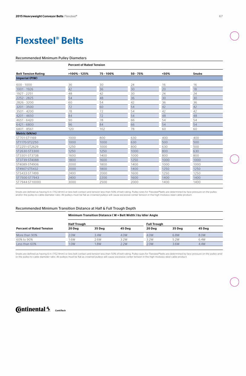
67 2015 Heavyweight Conveyor Belts Flexsteel®
Recommended Minimum Pulley Diameters
Percent of Rated Tension
Belt Tension Rating >100% - 125% 75 - 100% 50 - 75% <50% Snubs
Imperial (PIW)
600 - 1000 36 30 24 16 16
1001 - 1926 42 36 30 20 18
1927 - 2251 48 42 30 24 24
2252 - 2825 54 48 36 30 30
2826 - 3200 60 54 42 36 36
3201 - 3500 72 60 54 42 42
3501 - 4200 78 72 54 42 42
4201 - 4650 84 72 54 48 48
4651 - 6420 90 78 66 54 54
6421 - 6800 96 84 66 54 54
6801 - 8561 120 102 78 60 60
Metric (kN/m)
ST701-ST1169 1000 800 630 400 400
ST1170-ST2250 1000 1000 630 500 500
ST2251-ST2629 1250 1000 800 630 500
ST2630-ST3300 1250 1250 1000 800 630
ST3301-ST3738 1600 1400 1000 800 800
ST3739-ST4088 1800 1600 1250 1000 1000
ST4089-ST4906 2000 1800 1400 1000 1000
ST4907-ST5432 2000 1800 1400 1250 1250
ST5433-ST7499 2400 2000 1600 1250 1250
ST7500-ST7943 2400 2200 1600 1400 1400
ST7944-ST10000 3000 2500 2000 1400 1400
Snubs are defined as having 6 in. (152.4mm) or less belt contact and tension less than 50% of belt rating. Pulley sizes for Flexsteel®belts are determined by face pressure on the pulley and/or the pulley-to-cable diameter ratio. All pulleys must be flat as crowned pulleys will cause excessive center tension in the high modulus steel cable product.
Flexsteel® Belts
Recommended Minimum Transition Distance at Half & Full Trough Depth
Minimum Transition Distance ( W = Belt Width ) by Idler Angle
Half Trough Full Trough
Percent of Rated Tension 20 Deg 35 Deg 45 Deg 20 Deg 35 Deg 45 Deg
More than 90% 2.0W 3.4W 4.0W 4.0W 6.8W 8.0W
60% to 90% 1.6W 2.6W 3.2W 3.2W 5.2W 6.4W
Less than 60% 1.0W 1.8W 2.2W 2.0W 3.6W 4.4W
Snubs are defined as having 6 in. (152.4mm) or less belt contact and tension less than 50% of belt rating. Pulley sizes for Flexsteel®belts are determined by face pressure on the pulley and/or the pulley-to-cable diameter ratio. All pulleys must be flat as crowned pulleys will cause excessive center tension in the high modulus steel cable product.
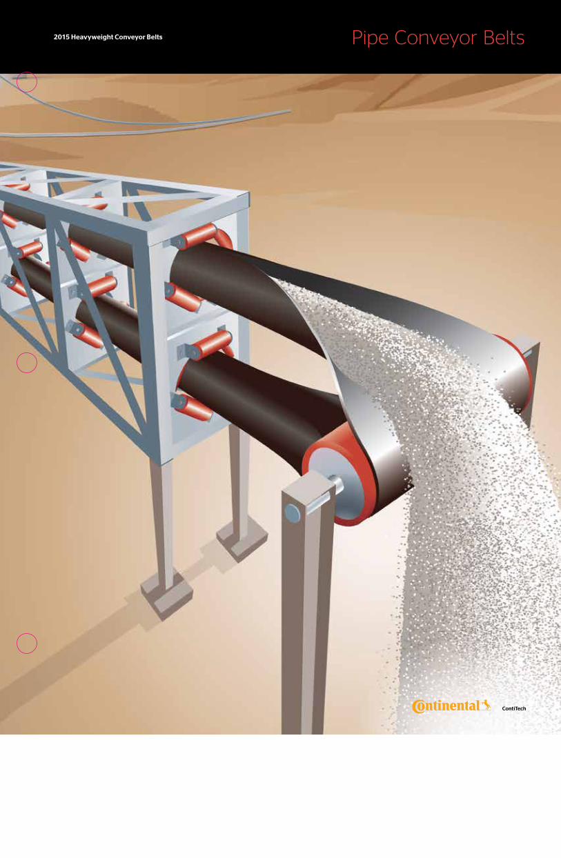
2015 Heavyweight Conveyor Belts Pipe Conveyor Belts
™
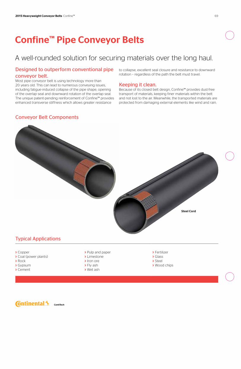
› › ›
Conveyor Belt Components
Typical Applications
› Copper› Coal (power plants)› Rock› Gypsum› Cement
› Pulp and paper› Limestone› Iron ore› Fly ash› Wet ash
› Fertilizer› Glass› Steel› Wood chips
Fabric
Steel Cord
Designed to outperform conventional pipe conveyor belt.Most pipe conveyor belt is using technology more than 20 years old. This can lead to numerous conveying issues, including fatigue-induced collapse of the pipe shape, opening of the overlap seal and downward rotation of the overlap seal. The unique patent-pending reinforcement of Confine™ provides enhanced transverse stiffness which allows greater resistance
to collapse, excellent seal closure and resistance to downward rotation – regardless of the path the belt must travel.
Keeping it clean.Because of its closed belt design, Confine™ provides dust-free transport of materials, keeping finer materials within the belt and not lost to the air. Meanwhile, the transported materials are protected from damaging external elements like wind and rain.
Confine™ Pipe Conveyor Belts
A well-rounded solution for securing materials over the long haul.
69 2015 Heavyweight Conveyor Belts Confine™
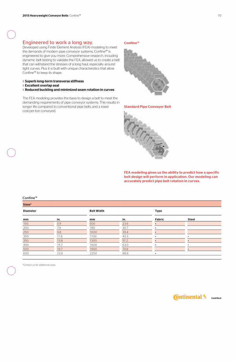
Engineered to work a long way.Developed using Finite Element Analysis (FEA) modeling to meet the demands of modern pipe conveyor systems, Confine™ is engineered to give you more. Comprehensive research, including dynamic belt testing to validate the FEA, allowed us to create a belt that can withstand the stresses of a long haul, especially around tight curves. Plus it is built with unique characteristics that allow Confine™ to keep its shape.
› Superb long-term transverse stiffness › Excellent overlap seal › Reduced buckling and minimized seam rotation in curves
The FEA modeling provides the basis to design a belt to meet the demanding requirements of pipe conveyor systems. This results in longer life compared to conventional pipe belts and a lower cost-per-ton conveyed.
FEA modeling gives us the ability to predict how a specific belt design will perform in application. Our modeling can accurately predict pipe belt rotation in curves.
Standard Pipe Conveyor Belt
Confine™
Confine™
Sizes*
Diameter Belt Width Type
mm in. mm in. Fabric Steel
150 5.9 600 23.6 •
200 7.9 780 30.7 •
250 9.8 1000 39.4 •
300 11.8 1100 43.3 • •
350 13.8 1300 51.2 • •
400 15.7 1600 63.0 • •
500 19.7 1900 74.8 •
600 23.6 2250 88.6 •
*Contact us for additional sizes.
70 2015 Heavyweight Conveyor Belts Confine™

2015 Heavyweight Conveyor Belts Cover Compounds
™
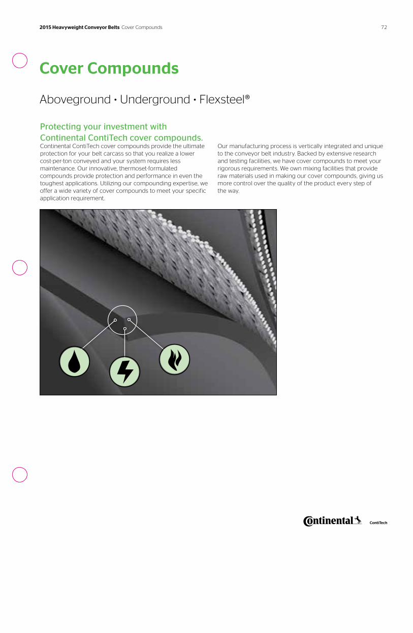
72
Cover Compounds
Aboveground • Underground • Flexsteel®
Protecting your investment with Continental ContiTech cover compounds. Continental ContiTech cover compounds provide the ultimate protection for your belt carcass so that you realize a lower cost-per-ton conveyed and your system requires less maintenance. Our innovative, thermoset-formulated compounds provide protection and performance in even the toughest applications. Utilizing our compounding expertise, we offer a wide variety of cover compounds to meet your specific application requirement.
Our manufacturing process is vertically integrated and unique to the conveyor belt industry. Backed by extensive research and testing facilities, we have cover compounds to meet your rigorous requirements. We own mixing facilities that provide raw materials used in making our cover compounds, giving us more control over the quality of the product every step of the way.
2015 Heavyweight Conveyor Belts Cover Compounds
73 2015 Heavyweight Conveyor Belts Cover Compounds
Cover CompoundsApplications
Cover Compounds
Markets
Compounds U
nd
erg
rou
nd
C
oal
Min
ing
Un
de
rgro
un
d
Min
ing
No
n-C
oal
Co
al –
Pre
p P
lan
ts
Ag
gre
gat
e
Ce
me
nt
Wo
od
– P
ulp
&
Pap
er
Ste
el o
r F
ou
nd
ry
Pac
kag
e H
and
ling
Har
d R
ock
Min
ing
Gra
in H
and
ling
Bu
lk H
and
ling
Te
rmin
al
Po
we
r G
en
era
tio
n
Bag
gag
e H
and
ling
San
d &
Gra
vel
Ove
rlan
d
Tran
spo
rtat
ion
Alumina – HOT •
ARMA® • • •
ARMA® II • • •
ARMA® ORSC • • • • •
ARMA®-SBR • • • •
Armatough • • •
DEFENDER Plus® • • • • • • • • • • • •
Easyrider™ •
FRAS-C • • • • •
Grade II • • •
HT Nitrile • •
Monster Hide • •
MORS •
PATHFINDER® Supreme •
Protector • • •
SHIELD™ • • •
Solar-Shield® XL 750 • • •
Stacker® • • • • • • •
Survivor® • • • • • • •
Survivor® Plus • • • • • • •
6740A • • •
74
Standard CompoundsAboveground • Underground • Flexsteel®
Alumina – HOT: Specifically designed compound intended for usage at alumina facilities where the alumina product is at or above 160°F (71°C).
ARMA® (Abrasion Resistant, Mining Application): Designed for non-coal mining underground applications that meets ASTM D378-13.2 (old MSHA CFR 30 part 18) flame test standard and provides good abrasion resistant characteristics.
ARMA® II: Designed for non-coal underground mining and surface applications that meets ASTM D378-13.2 (old MSHA CFR 30 part 18) flame test standard and offers 35% more abrasion resistance than ARMA®-SBR.
ARMA® ORSC: Moderate resistance to oil and static conductive, this compound is designed for oily coal or coke material. ARMA® meets ASTM D378-13.2 (old MSHA CFR 30 part 18) flame test standard.
ARMA®-SBR: Designed especially for above-ground prep plants/power plant applications mining underground and meets ASTM D378-13.2 (old MSHA CFR 30 part 18) flame test standard.
Armatough: Designed for the underground coal mining market, it meets the MSHA CFR part 14 (B.E.L.T.) flame test standard, is an ARPM Grade II compound that is ozone resistant and offers 65% more abrasion resistance than SHIELD.™ The compound is designed for the most abusive underground applications including slope belts.
DEFENDER® Plus: An ARPM Grade I rubber compound designed to provide excellent abrasion resistance, very good gouge resis-tance and excellent flexing life.
Easyrider®: A low rolling resistance family of compounds for the pulley cover side only which is designed to reduce the energy cost by minimizing indention energy loss to idlers. Proven with almost 400 miles of belt in operation, the LRR Easyrider™ compound can provide up to 20% reduction in energy consumption compared to standard compounds and the SLRR Easyrider™ compound can provide up to 32% reduction in energy consumption.
FRAS-SA & FRAS-C: Fire retardant antistatic belting is certified by the Canadian Department of Energy, Mines and Resources, Ottawa to CAN/CSA M422M87, Type C, for below surface use as well as other mining operations. FRAS-SA offers minimum of 40% better abrasion resistance than FRAS-C compound.
GLOBAL X®: Meets ARPM Grade I and DIN X standards. Offers superior cut, gouge resistance and very good abrasion resistance.
GRADE II: An ARPM Grade II rubber compound designed to provide good abrasion and gouge resistance and very good flex life.
HT Nitrile: An oil resistant compound formulated for applications demanding higher resistance to heat, oil and abrasion. It is resistant to temperatures up to 300°F (149°C), abrasion flexing, oxidation and the effect of corrosive atmospheres.
Monster Hide: Monster Hide is a ARPM Grade II compound providing the ultimate in cut and gouge protection. The compound is designed to absorb impacts from large sharp rock.
MORS: Compounded to resist the terpene content of wood chips and moderately oily grains. It has fair abrasion resistance and is a good value for handling moderately oily material where fire resistance is not required.
PATHFINDER® Supreme: Designed especially for the grain industry where oily grains and controlled mineral or vegetable oil dust suppressive sprays come in contact with the belt.
PATHFINDER® Arctic: Designed especially for the grain industry where oily grains and controlled mineral or vegetable oil dust suppressive sprays come in contact with the belt. Suitable to -40˚F (-40°C). Protector: A Grade II compound for applications requiring good abrasion and gouge resistance and very good flex life.
SHIELD™: Underground coal mining compound that meets MSHA CFR 30 part 14 (B.E.L.T.) flame test standard. Virtually halogen-free self extinguishing compound that produces very low smoke and toxicity levels. SHIELD-OZ is an above ground compound that meets MSHA CFR 30 part 14 (B.E.L.T.) flame test standard.
Solar-Shield® XL 750: An exceptional hot material compound with superior heat resistance against hardening and cracking. It is designed to carry hot loads at intermittent temperatures up to 750˚F (399°C) and retain its superior heat resistant qualities.
Stacker®: Premium ARPM Grade I Rubber Compound, designed for excellent resistance to cutting, gouging and abrasion.
Survivor®: Superior abrasion resistance. Ideal for high speed, small diameter crushed stone, trap rock, ore, copper, taconite and other abrasive applications.
Survivor® Plus: The ultimate in abrasion resistance, offering up to 40% more abrasion resistance than Survivor.® Ideal for high speed, abrasive material applications.
6740A: Compounded for excellent heat and abrasion resistance in temperature ranges of 350˚F (177°C) for lumpy material and up to 250˚F (121°C) for hot baking loads.
2015 Heavyweight Conveyor Belts Cover Compounds
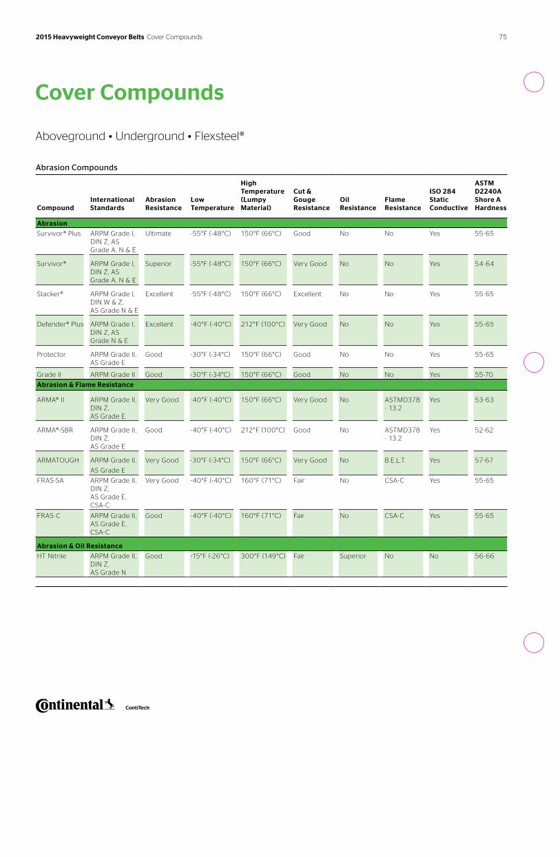
75 2015 Heavyweight Conveyor Belts Cover Compounds
Cover Compounds
Aboveground • Underground • Flexsteel®
Abrasion Compounds
Compound
International Standards
Abrasion Resistance
Low Temperature
High Temperature (Lumpy Material)
Cut & Gouge Resistance
Oil Resistance
Flame Resistance
ISO 284 Static Conductive
ASTM D2240A Shore A Hardness
Abrasion
Survivor® Plus ARPM Grade I, DIN Z, AS Grade A, N & E
Ultimate -55°F (-48°C) 150°F (66°C) Good No No Yes 55-65
Survivor® ARPM Grade I, DIN Z, AS Grade A, N & E
Superior -55°F (-48°C) 150°F (66°C) Very Good No No Yes 54-64
Stacker® ARPM Grade I, DIN W & Z, AS Grade N & E
Excellent -55°F (-48°C) 150°F (66°C) Excellent No No Yes 55-65
Defender® Plus ARPM Grade I, DIN Z, AS Grade N & E
Excellent -40°F (-40°C) 212°F (100°C) Very Good No No Yes 55-65
Protector ARPM Grade II, AS Grade E
Good -30°F (-34°C) 150°F (66°C) Good No No Yes 55-65
Grade II ARPM Grade II Good -30°F (-34°C) 150°F (66°C) Good No No Yes 55-70
Abrasion & Flame Resistance
ARMA® II ARPM Grade II, DIN Z, AS Grade E
Very Good -40°F (-40°C) 150°F (66°C) Very Good No ASTMD378 - 13.2
Yes 53-63
ARMA®-SBR ARPM Grade II, DIN Z, AS Grade E
Good -40°F (-40°C) 212°F (100°C) Good No ASTMD378 - 13.2
Yes 52-62
ARMATOUGH ARPM Grade II,
AS Grade E
Very Good -30°F (-34°C) 150°F (66°C) Very Good No B.E.L.T. Yes 57-67
FRAS-SA ARPM Grade II, DIN Z, AS Grade E, CSA-C
Very Good -40°F (-40°C) 160°F (71°C) Fair No CSA-C Yes 55-65
FRAS-C ARPM Grade II, AS Grade E, CSA-C
Good -40°F (-40°C) 160°F (71°C) Fair No CSA-C Yes 55-65
Abrasion & Oil Resistance
HT Nitrile ARPM Grade II, DIN Z, AS Grade N
Good -15°F (-26°C) 300°F (149°C) Fair Superior No No 56-66
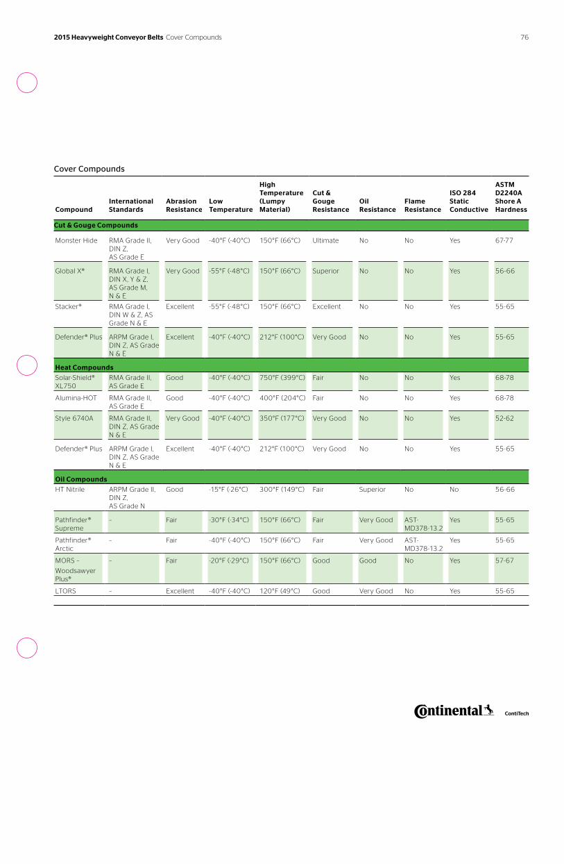
76
Cover Compounds
Compound
International Standards
Abrasion Resistance
Low Temperature
High Temperature (Lumpy Material)
Cut & Gouge Resistance
Oil Resistance
Flame Resistance
ISO 284 Static Conductive
ASTM D2240A Shore A Hardness
Cut & Gouge Compounds
Monster Hide RMA Grade II, DIN Z, AS Grade E
Very Good -40°F (-40°C) 150°F (66°C) Ultimate No No Yes 67-77
Global X® RMA Grade I, DIN X, Y & Z, AS Grade M, N & E
Very Good -55°F (-48°C) 150°F (66°C) Superior No No Yes 56-66
Stacker® RMA Grade I, DIN W & Z, AS Grade N & E
Excellent -55°F (-48°C) 150°F (66°C) Excellent No No Yes 55-65
Defender® Plus ARPM Grade I, DIN Z, AS Grade N & E
Excellent -40°F (-40°C) 212°F (100°C) Very Good No No Yes 55-65
Heat Compounds
Solar-Shield® XL750
RMA Grade II, AS Grade E
Good -40°F (-40°C) 750°F (399°C) Fair No No Yes 68-78
Alumina-HOT RMA Grade II, AS Grade E
Good -40°F (-40°C) 400°F (204°C) Fair No No Yes 68-78
Style 6740A RMA Grade II, DIN Z, AS Grade N & E
Very Good -40°F (-40°C) 350°F (177°C) Very Good No No Yes 52-62
Defender® Plus ARPM Grade I, DIN Z, AS Grade N & E
Excellent -40°F (-40°C) 212°F (100°C) Very Good No No Yes 55-65
Oil Compounds
HT Nitrile ARPM Grade II, DIN Z, AS Grade N
Good -15°F (-26°C) 300°F (149°C) Fair Superior No No 56-66
Pathfinder® Supreme
– Fair -30°F (-34°C) 150°F (66°C) Fair Very Good AST-MD378-13.2
Yes 55-65
Pathfinder® Arctic
– Fair -40°F (-40°C) 150°F (66°C) Fair Very Good AST-MD378-13.2
Yes 55-65
MORS –
Woodsawyer Plus®
– Fair -20°F (-29°C) 150°F (66°C) Good Good No Yes 57-67
LTORS – Excellent -40°F (-40°C) 120°F (49°C) Good Very Good No Yes 55-65
2015 Heavyweight Conveyor Belts Cover Compounds
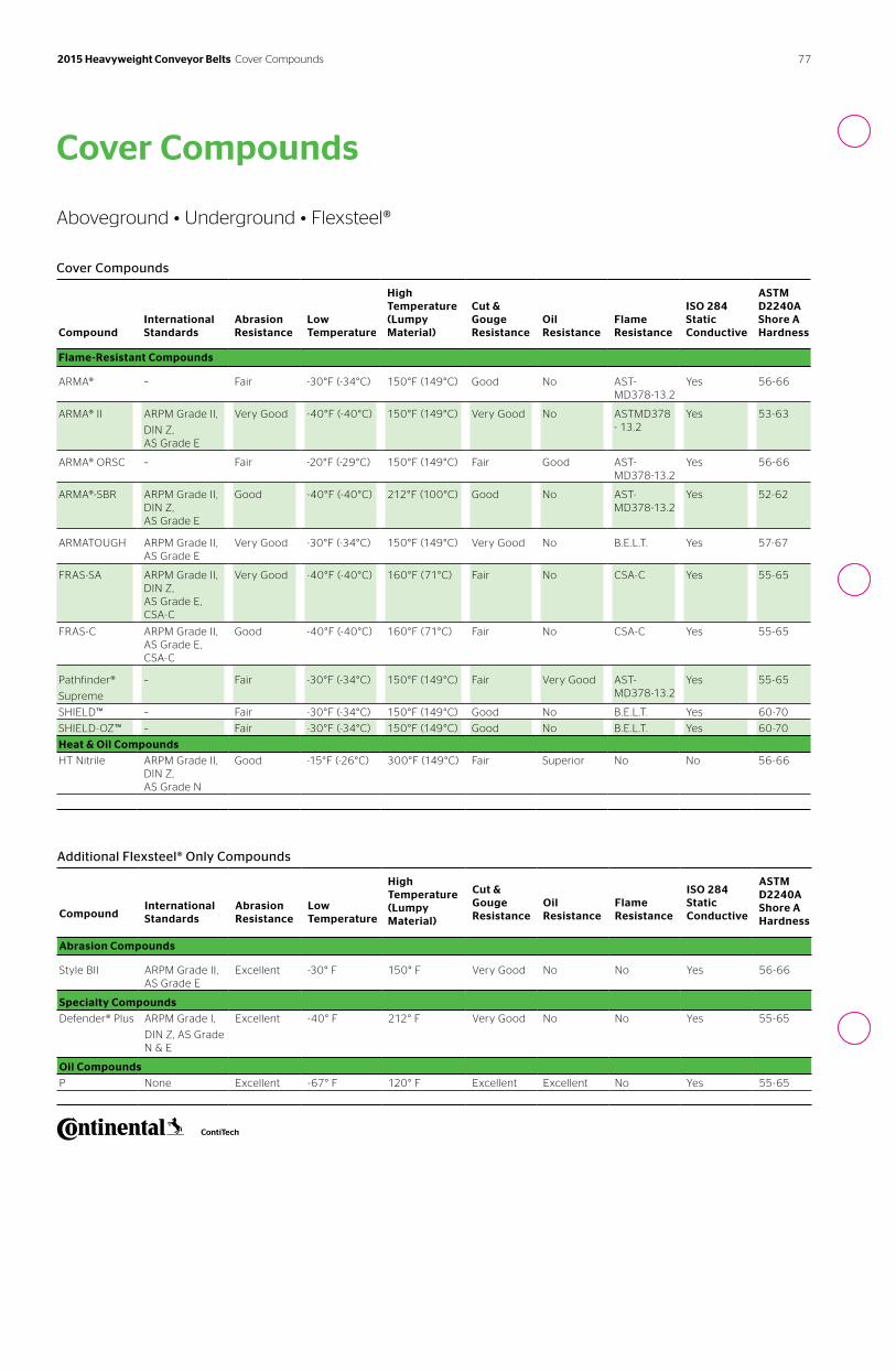
77 2015 Heavyweight Conveyor Belts Cover Compounds
Cover Compounds
Aboveground • Underground • Flexsteel®
Additional Flexsteel® Only Compounds
CompoundInternational Standards
Abrasion Resistance
Low Temperature
High Temperature (Lumpy Material)
Cut & Gouge Resistance
Oil Resistance
Flame Resistance
ISO 284 Static Conductive
ASTM D2240A Shore A Hardness
Abrasion Compounds
Style BII ARPM Grade II, AS Grade E
Excellent -30° F 150° F Very Good No No Yes 56-66
Specialty Compounds
Defender® Plus ARPM Grade I,
DIN Z, AS Grade N & E
Excellent -40° F 212° F Very Good No No Yes 55-65
Oil Compounds
P None Excellent -67° F 120° F Excellent Excellent No Yes 55-65
Cover Compounds
Compound
International Standards
Abrasion Resistance
Low Temperature
High Temperature (Lumpy Material)
Cut & Gouge Resistance
Oil Resistance
Flame Resistance
ISO 284 Static Conductive
ASTM D2240A Shore A Hardness
Flame-Resistant Compounds
ARMA® – Fair -30°F (-34°C) 150°F (149°C) Good No AST-MD378-13.2
Yes 56-66
ARMA® II ARPM Grade II,
DIN Z, AS Grade E
Very Good -40°F (-40°C) 150°F (149°C) Very Good No ASTMD378 - 13.2
Yes 53-63
ARMA® ORSC – Fair -20°F (-29°C) 150°F (149°C) Fair Good AST-MD378-13.2
Yes 56-66
ARMA®-SBR ARPM Grade II, DIN Z, AS Grade E
Good -40°F (-40°C) 212°F (100°C) Good No AST-MD378-13.2
Yes 52-62
ARMATOUGH ARPM Grade II, AS Grade E
Very Good -30°F (-34°C) 150°F (149°C) Very Good No B.E.L.T. Yes 57-67
FRAS-SA ARPM Grade II, DIN Z, AS Grade E, CSA-C
Very Good -40°F (-40°C) 160°F (71°C) Fair No CSA-C Yes 55-65
FRAS-C ARPM Grade II, AS Grade E, CSA-C
Good -40°F (-40°C) 160°F (71°C) Fair No CSA-C Yes 55-65
Pathfinder®
Supreme
– Fair -30°F (-34°C) 150°F (149°C) Fair Very Good AST-MD378-13.2
Yes 55-65
SHIELD™ – Fair -30°F (-34°C) 150°F (149°C) Good No B.E.L.T. Yes 60-70
SHIELD-OZ™ – Fair -30°F (-34°C) 150°F (149°C) Good No B.E.L.T. Yes 60-70
Heat & Oil Compounds
HT Nitrile ARPM Grade II, DIN Z, AS Grade N
Good -15°F (-26°C) 300°F (149°C) Fair Superior No No 56-66
Total Guard™ Belt Monitoring SystemsGuard your investment. Prevent downtime.
2015 Heavyweight Conveyor Belts Total Guard™
™
Belt Monitoring Systems
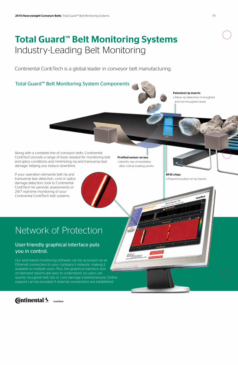
Total Guard™ Belt Monitoring Systems Industry-Leading Belt Monitoring
Continental ContiTech is a global leader in conveyor belt manufacturing.
Total Guard™ Belt Monitoring System Components
Network of Protection
User-friendly graphical interface puts you in control.
Our web-based monitoring software can be accessed via an Ethernet connection to your company’s network, making it available to multiple users. Plus, the graphical interface and on-demand reports are easy to understand, so users can quickly recognize belt rips or cord damage instantaneously. Online support can be provided if external connections are established.
Profiled sensor arrays
› Identify rips immediately
after critical loading points
RFID chips
› Pinpoint location of rip inserts
Patented rip inserts
› Allow rip detection in troughed
and non-troughed areas
Along with a complete line of conveyor belts, Continental ContiTech provide a range of tools needed for monitoring belt and splice conditions and minimizing rip and transverse tear damage, helping you reduce downtime.
If your operation demands belt rip and transverse tear detection, cord or splice damage detection, look to Continental ContiTech for periodic assessments or 24/7 real-time monitoring of your Continental ContiTech belt systems.
79 2015 Heavyweight Conveyor Belts Total Guard™ Belt Monitoring Systems
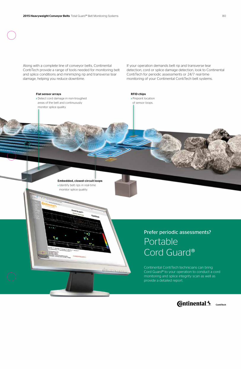
Along with a complete line of conveyor belts, Continental ContiTech provide a range of tools needed for monitoring belt and splice conditions and minimizing rip and transverse tear damage, helping you reduce downtime.
If your operation demands belt rip and transverse tear detection, cord or splice damage detection, look to Continental ContiTech for periodic assessments or 24/7 real-time monitoring of your Continental ContiTech belt systems.
RFID chips
› Pinpoint location
of sensor loops.
Embedded, closed-circuit loops
› Identify belt rips in real-time
monitor splice quality.
Prefer periodic assessments?
Portable Cord Guard®
Continental ContiTech technicians can bring Cord Guard® to your operation to conduct a cord monitoring and splice integrity scan as well as provide a detailed report.
Flat sensor arrays
› Detect cord damage in non-troughed
areas of the belt and continuously
monitor splice quality.
80 2015 Heavyweight Conveyor Belts Total Guard™ Belt Monitoring Systems
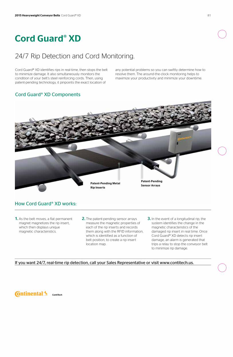
Cord Guard® XD Components
Cord Guard® XD
24/7 Rip Detection and Cord Monitoring.
Cord Guard® XD identifies rips in real-time, then stops the belt to minimize damage. It also simultaneously monitors the condition of your belt’s steel reinforcing cords. Then, using patent-pending technology, it pinpoints the exact location of
any potential problems so you can swiftly determine how to resolve them. The around-the-clock monitoring helps to maximize your productivity and minimize your downtime.
Patent-Pending Metal
Rip Inserts
Patent-Pending
Sensor Arrays
How Cord Guard® XD works:
1. As the belt moves, a flat permanent magnet magnetizes the rip insert, which then displays unique magnetic characteristics.
2. The patent-pending sensor arrays measure the magnetic properties of each of the rip inserts and records them along with the RFID information, which is identified as a function of belt position, to create a rip insert location map.
3. In the event of a longitudinal rip, the system identifies the change in the magnetic characteristics of the damaged rip insert in real time. Once Cord Guard® XD detects rip insert damage, an alarm is generated that trips a relay to stop the conveyor belt to minimize rip damage.
If you want 24/7, real-time rip detection, call your Sales Representative or visit www.contitech.us.
81 2015 Heavyweight Conveyor Belts Cord Guard® XD
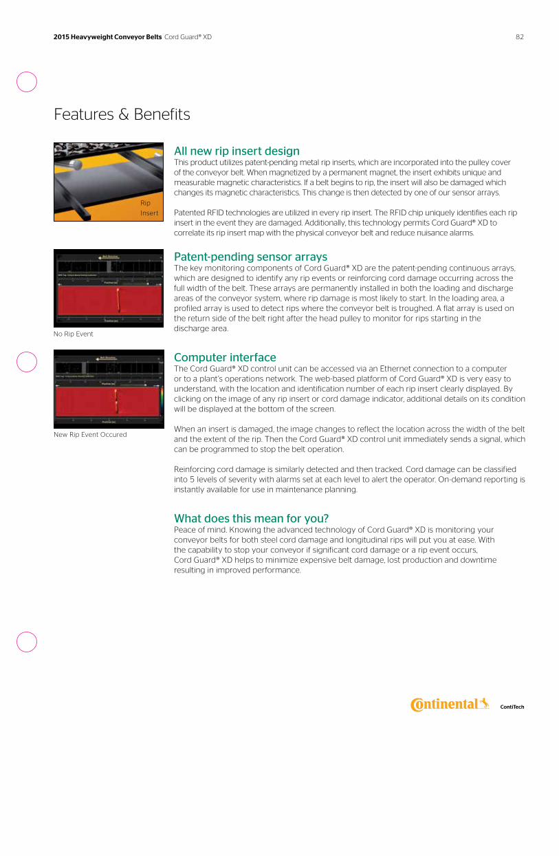
Features & Benefits
All new rip insert designThis product utilizes patent-pending metal rip inserts, which are incorporated into the pulley cover of the conveyor belt. When magnetized by a permanent magnet, the insert exhibits unique and measurable magnetic characteristics. If a belt begins to rip, the insert will also be damaged which changes its magnetic characteristics. This change is then detected by one of our sensor arrays.
Patented RFID technologies are utilized in every rip insert. The RFID chip uniquely identifies each rip insert in the event they are damaged. Additionally, this technology permits Cord Guard® XD to correlate its rip insert map with the physical conveyor belt and reduce nuisance alarms.
Patent-pending sensor arraysThe key monitoring components of Cord Guard® XD are the patent-pending continuous arrays, which are designed to identify any rip events or reinforcing cord damage occurring across the full width of the belt. These arrays are permanently installed in both the loading and discharge areas of the conveyor system, where rip damage is most likely to start. In the loading area, a profiled array is used to detect rips where the conveyor belt is troughed. A flat array is used on the return side of the belt right after the head pulley to monitor for rips starting in the discharge area.
Computer interfaceThe Cord Guard® XD control unit can be accessed via an Ethernet connection to a computer or to a plant’s operations network. The web-based platform of Cord Guard® XD is very easy to understand, with the location and identification number of each rip insert clearly displayed. By clicking on the image of any rip insert or cord damage indicator, additional details on its condition will be displayed at the bottom of the screen.
When an insert is damaged, the image changes to reflect the location across the width of the belt and the extent of the rip. Then the Cord Guard® XD control unit immediately sends a signal, which can be programmed to stop the belt operation.
Reinforcing cord damage is similarly detected and then tracked. Cord damage can be classified into 5 levels of severity with alarms set at each level to alert the operator. On-demand reporting is instantly available for use in maintenance planning.
What does this mean for you? Peace of mind. Knowing the advanced technology of Cord Guard® XD is monitoring your conveyor belts for both steel cord damage and longitudinal rips will put you at ease. With the capability to stop your conveyor if significant cord damage or a rip event occurs, Cord Guard® XD helps to minimize expensive belt damage, lost production and downtime resulting in improved performance.
Rip
Insert
No Rip Event
New Rip Event Occured
82 2015 Heavyweight Conveyor Belts Cord Guard® XD
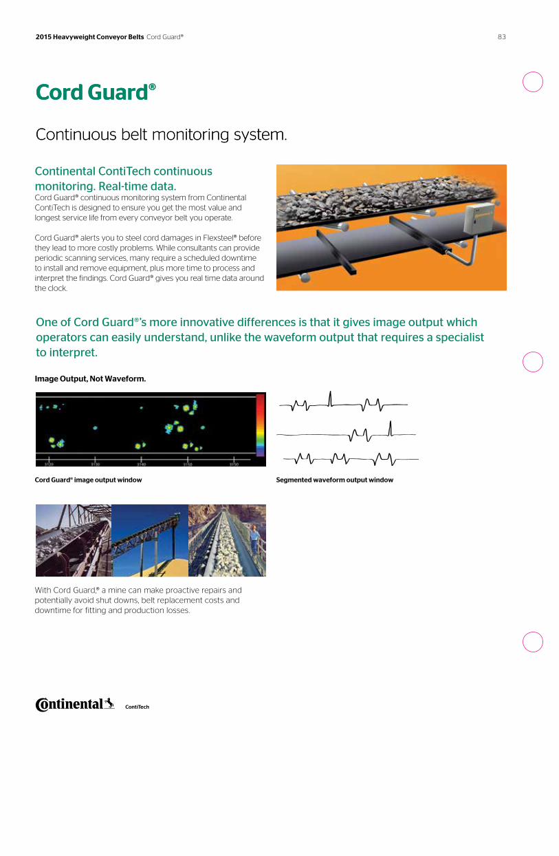
Continental ContiTech continuous monitoring. Real-time data. Cord Guard® continuous monitoring system from Continental ContiTech is designed to ensure you get the most value and longest service life from every conveyor belt you operate.
Cord Guard® alerts you to steel cord damages in Flexsteel® before they lead to more costly problems. While consultants can provide periodic scanning services, many require a scheduled downtime to install and remove equipment, plus more time to process and interpret the findings. Cord Guard® gives you real time data around the clock.
Image Output, Not Waveform.
Cord Guard® image output window
With Cord Guard,® a mine can make proactive repairs and potentially avoid shut downs, belt replacement costs and downtime for fitting and production losses.
Cord Guard® Continuous belt monitoring system.
One of Cord Guard®’s more innovative differences is that it gives image output which operators can easily understand, unlike the waveform output that requires a specialist to interpret.
Segmented waveform output window
Cord Guard® Continuous belt monitoring system.
83 2015 Heavyweight Conveyor Belts Cord Guard®
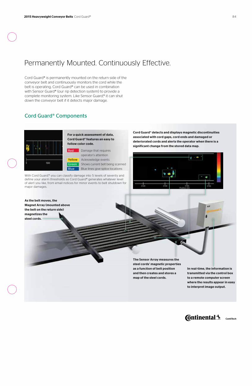
Cord Guard® Components
In real-time, the information is
transmitted via the control box
to a remote computer screen
where the results appear in easy
to interpret image output.
Cord Guard® is permanently mounted on the return side of the conveyor belt and continuously monitors the cord while the belt is operating. Cord Guard® can be used in combination with Sensor Guard® (our rip detection system) to provide a complete monitoring system. Like Sensor Guard,® it can shut down the conveyor belt if it detects major damage.
Permanently Mounted. Continuously Effective.
The Sensor Array measures the
steel cords’ magnetic properties
as a function of belt position
and then creates and stores a
map of the steel cords.
Cord Guard® detects and displays magnetic discontinuities
associated with cord gaps, cord ends and damaged or
deteriorated cords and alerts the operator when there is a
significant change from the stored data map.
As the belt moves, the
Magnet Array (mounted above
the belt on the return side)
magnetizes the
steel cords.
For a quick assessment of data,
Cord Guard® features an easy to
follow color code.
Red Damage that requires
operator’s attention
Yellow Acknowledge events
Green Shows current belt being scanned
Blue Blue lines give splice locations
With Cord Guard,® you can classify damage into 5 levels of severity and define your alarm thresholds so Cord Guard® generates whatever level of alert you like, from email notices for minor events to belt shutdown for major damages.
84 2015 Heavyweight Conveyor Belts Cord Guard®
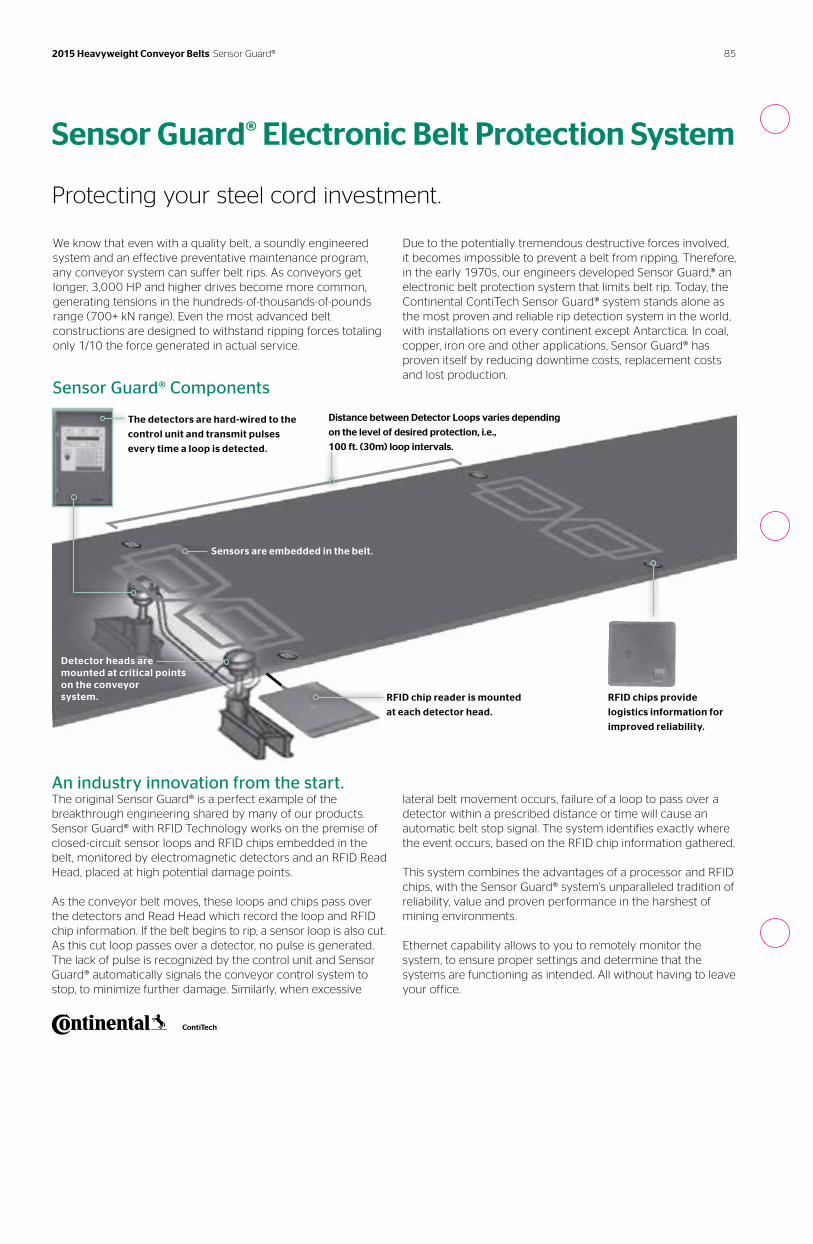
Sensor Guard® Components
Sensor Guard® Electronic Belt Protection System
Protecting your steel cord investment.
We know that even with a quality belt, a soundly engineered system and an effective preventative maintenance program, any conveyor system can suffer belt rips. As conveyors get longer, 3,000 HP and higher drives become more common, generating tensions in the hundreds-of-thousands-of-pounds range (700+ kN range). Even the most advanced belt constructions are designed to withstand ripping forces totaling only 1/10 the force generated in actual service.
Due to the potentially tremendous destructive forces involved, it becomes impossible to prevent a belt from ripping. Therefore, in the early 1970s, our engineers developed Sensor Guard,® an electronic belt protection system that limits belt rip. Today, the Continental ContiTech Sensor Guard® system stands alone as the most proven and reliable rip detection system in the world, with installations on every continent except Antarctica. In coal, copper, iron ore and other applications, Sensor Guard® has proven itself by reducing downtime costs, replacement costs and lost production.
The detectors are hard-wired to the
control unit and transmit pulses
every time a loop is detected.
Distance between Detector Loops varies depending
on the level of desired protection, i.e.,
100 ft. (30m) loop intervals.
Sensors are embedded in the belt.
An industry innovation from the start.The original Sensor Guard® is a perfect example of the breakthrough engineering shared by many of our products. Sensor Guard® with RFID Technology works on the premise of closed-circuit sensor loops and RFID chips embedded in the belt, monitored by electromagnetic detectors and an RFID Read Head, placed at high potential damage points.
As the conveyor belt moves, these loops and chips pass over the detectors and Read Head which record the loop and RFID chip information. If the belt begins to rip, a sensor loop is also cut. As this cut loop passes over a detector, no pulse is generated. The lack of pulse is recognized by the control unit and Sensor Guard® automatically signals the conveyor control system to stop, to minimize further damage. Similarly, when excessive
Detector heads are mounted at critical points on the conveyor system. RFID chip reader is mounted
at each detector head.
RFID chips provide
logistics information for
improved reliability.
lateral belt movement occurs, failure of a loop to pass over a detector within a prescribed distance or time will cause an automatic belt stop signal. The system identifies exactly where the event occurs, based on the RFID chip information gathered.
This system combines the advantages of a processor and RFID chips, with the Sensor Guard® system’s unparalleled tradition of reliability, value and proven performance in the harshest of mining environments.
Ethernet capability allows to you to remotely monitor the system, to ensure proper settings and determine that the systems are functioning as intended. All without having to leave your office.
85 2015 Heavyweight Conveyor Belts Sensor Guard®
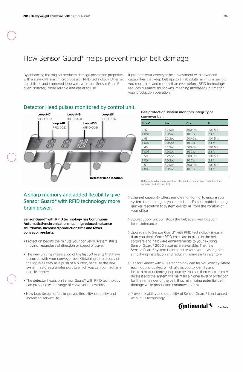
Detector Head pulses monitored by control unit.
It protects your conveyor belt investment with advanced capabilities that keep belt rips to an absolute minimum, saving you more time and money than ever before. RFID technology reduces nuisance shutdowns, meaning increased up-time for your production operation.
By enhancing the original product’s damage prevention properties with a state-of-the-art microprocessor, RFID technology, Ethernet capabilities and improved loop wire, we made Sensor Guard® even “smarter,” more reliable and easier to use.
How Sensor Guard® helps prevent major belt damage:
A sharp memory and added flexibility give Sensor Guard® with RFID technology more brain power.
Sensor Guard® with RFID technology has Continuous Automatic Synchronization meaning reduced nuisance shutdowns, increased production time and fewer conveyor re-starts.
› Protection begins the minute your conveyor system starts moving, regardless of direction or speed of travel.
› The new unit maintains a log of the last 50 events that have occurred with your conveyor belt. Obtaining a hard copy of the log is as easy as a push of a button, because the new system features a printer port to which you can connect any parallel printer.
› The detector heads on Sensor Guard® with RFID technology can protect a wider range of conveyor belt widths.
› New loop design offers improved flexibility, durability and increased service life.
› Ethernet capability offers remote monitoring, to ensure your system is operating as you intend it to. Faster troubleshooting, quicker resolution to system events, all from the comfort of your office
› Stop-at-Loop function stops the belt at a given location for maintenance.
› Upgrading to Sensor Guard® with RFID technology is easier than you think. Once RFID chips are in place in the belt, software and hardware enhancements to your existing Sensor Guard® 2000 systems are available. The new Sensor Guard® system is compatible with your existing belt, simplifying installation and reducing spare parts inventory.
› Sensor Guard® with RFID technology can tell you exactly where each loop is located, which allows you to identify and locate a malfunctioning loop quickly. You can then electronically delete it and the system will maintain a higher level of protection for the remainder of the belt, thus minimizing potential belt damage while production continues to flow.
› Proven reliability and durability of Sensor Guard® is enhanced with RFID technology.
Belt protection system monitors integrity of conveyor belt
Sizes* Sec. Cts. ft.
L 47 5.2 Sec. 500 Cts. 101.5 ft.
T 001 1.0 Sec. 10 Cts. 2.1 ft.
L 48 5.2 Sec. 500 Cts. 101.5 ft.
T 002 1.0 Sec. 10 Cts. 2.1 ft.
L 49 5.2 Sec. 500 Cts. 101.5 ft.
T 003 1.0 Sec. 10 Cts. 2.1 ft.
L 50 5.2 Sec. 500 Cts. 101.5 ft.
T 004 1.0 Sec. 10 Cts. 2.1 ft.
L 51 5.2 Sec. 500 Cts. 101.5 ft.
T 005 1.0 Sec. 10 Cts. 2.1 ft.
Detector head pinpoints position of impact or rip damage created on the conveyor belt at Loop #50.
Loop #47
(RFID 001)
Loop #49
(RFID 003)
Loop #48
(RFID 002)
Loop #51
(RFID 005)
Loop #50
(RFID 004)
Detector head location
86 2015 Heavyweight Conveyor Belts Sensor Guard®
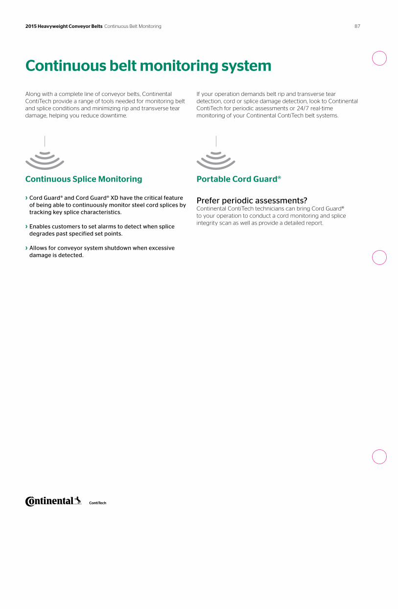
Along with a complete line of conveyor belts, Continental ContiTech provide a range of tools needed for monitoring belt and splice conditions and minimizing rip and transverse tear damage, helping you reduce downtime.
Continuous Splice Monitoring
› Cord Guard® and Cord Guard® XD have the critical feature of being able to continuously monitor steel cord splices by tracking key splice characteristics.
› Enables customers to set alarms to detect when splice degrades past specified set points.
› Allows for conveyor system shutdown when excessive damage is detected.
If your operation demands belt rip and transverse tear detection, cord or splice damage detection, look to Continental ContiTech for periodic assessments or 24/7 real-time monitoring of your Continental ContiTech belt systems.
Portable Cord Guard®
Prefer periodic assessments?Continental ContiTech technicians can bring Cord Guard® to your operation to conduct a cord monitoring and splice integrity scan as well as provide a detailed report.
Continuous belt monitoring system
87 2015 Heavyweight Conveyor Belts Continuous Belt Monitoring
2015 Heavyweight Conveyor Belts Additional Information
™
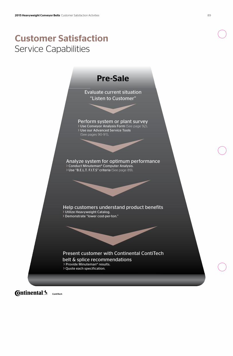
Evaluate current situation “Listen to Customer”
Pre-Sale
Customer SatisfactionService Capabilities
Perform system or plant survey › Use Conveyor Analysis Form (See page 92). › Use our Advanced Service Tools (See pages 90-91).
Analyze system for optimum performance › Conduct Minuteman® Computer Analysis. › Use “B.E.L.T. F.I.T.S” criteria (See page 89).
Help customers understand product benefits › Utilize Heavyweight Catalog. › Demonstrate “lower cost-per-ton.”
Present customer with Continental ContiTech belt & splice recommendations
› Provide Minuteman® results. › Quote each specification.
89 2015 Heavyweight Conveyor Belts Customer Satisfaction Activities
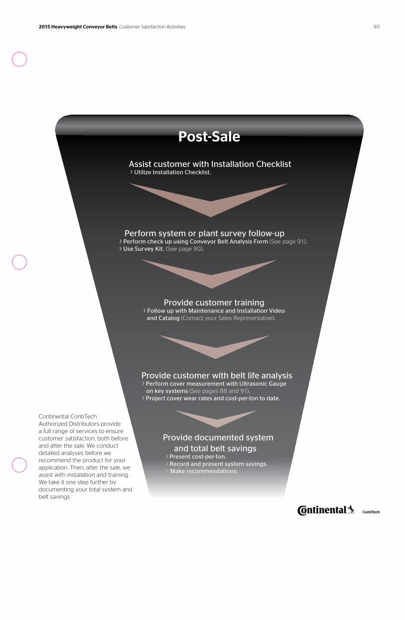
Continental ContiTech Authorized Distributors provide a full range of services to ensure customer satisfaction, both before and after the sale. We conduct detailed analyses before we recommend the product for your application. Then, after the sale, we assist with installation and training. We take it one step further by documenting your total system and belt savings.
Post-Sale
Assist customer with Installation Checklist › Utilize Installation Checklist.
Perform system or plant survey follow-up › Perform check up using Conveyor Belt Analysis Form (See page 91).
› Use Survey Kit. (See page 90).
Provide customer training › Follow up with Maintenance and Installation Video and Catalog (Contact your Sales Representative).
Provide customer with belt life analysis › Perform cover measurement with Ultrasonic Gauge on key systems (See pages 88 and 91). › Project cover wear rates and cost-per-ton to date.
Provide documented system and total belt savings
› Present cost-per-ton. › Record and present system savings. › Make recommendations.
90 2015 Heavyweight Conveyor Belts Customer Satisfaction Activities
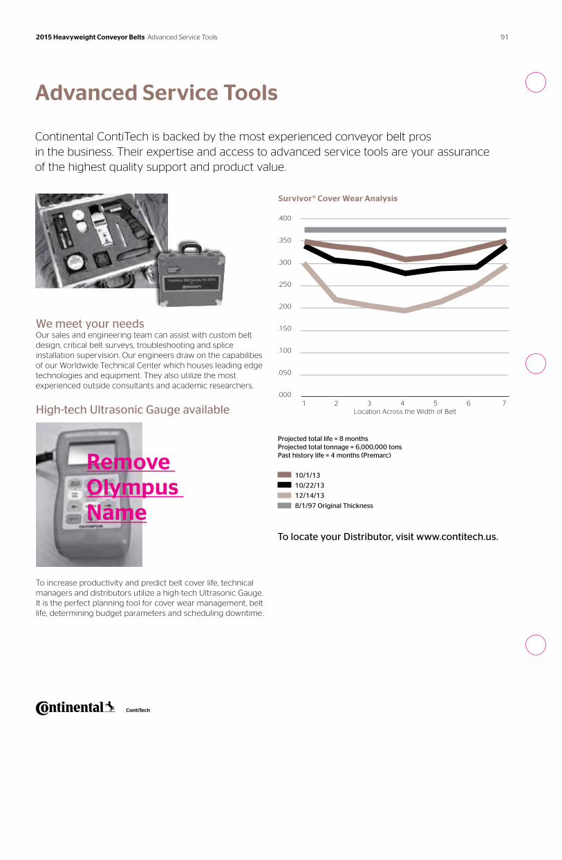
We meet your needsOur sales and engineering team can assist with custom belt design, critical belt surveys, troubleshooting and splice installation supervision. Our engineers draw on the capabilities of our Worldwide Technical Center which houses leading edge technologies and equipment. They also utilize the most experienced outside consultants and academic researchers.
High-tech Ultrasonic Gauge available
To increase productivity and predict belt cover life, technical managers and distributors utilize a high-tech Ultrasonic Gauge. It is the perfect planning tool for cover wear management, belt life, determining budget parameters and scheduling downtime.
To locate your Distributor, visit www.contitech.us.
Advanced Service Tools
Continental ContiTech is backed by the most experienced conveyor belt pros in the business. Their expertise and access to advanced service tools are your assurance of the highest quality support and product value.
Survivor® Cover Wear Analysis
Projected total life = 8 monthsProjected total tonnage = 6,000,000 tonsPast history life = 4 months (Premarc)
10/1/13
10/22/13
12/14/13
8/1/97 Original Thickness
1 2 3 4 5 6 7Location Across the Width of Belt
.400
.350
.300
.250
.200
.150
.100
.050
.000
Remove Olympus Name
91 2015 Heavyweight Conveyor Belts Advanced Service Tools
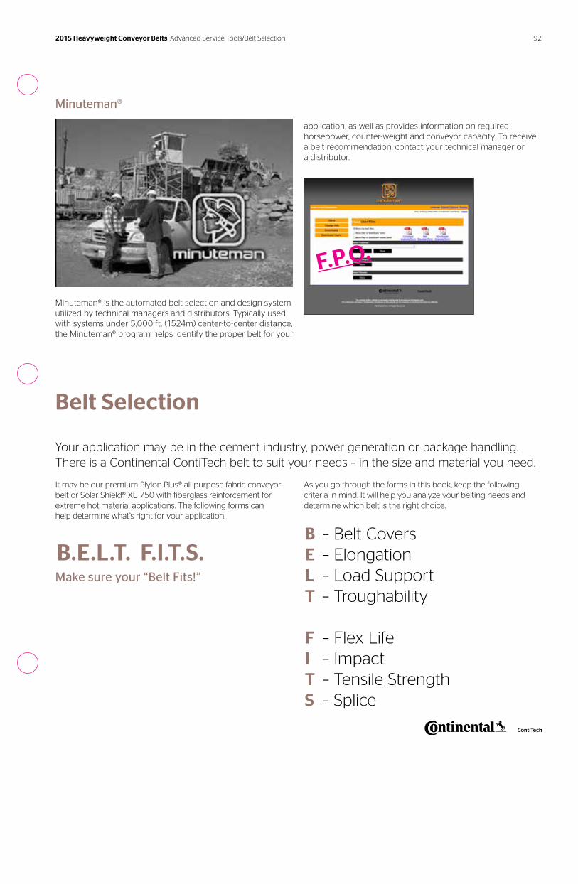
It may be our premium Plylon Plus® all-purpose fabric conveyor belt or Solar Shield® XL 750 with fiberglass reinforcement for extreme hot material applications. The following forms can help determine what’s right for your application.
Belt Selection
Your application may be in the cement industry, power generation or package handling. There is a Continental ContiTech belt to suit your needs – in the size and material you need.
As you go through the forms in this book, keep the following criteria in mind. It will help you analyze your belting needs and determine which belt is the right choice.
B ELT
FITS
– Belt Covers– Elongation– Load Support– Troughability
– Flex Life– Impact– Tensile Strength– Splice
B.E.L.T. F.I.T.S.Make sure your “Belt Fits!”
Minuteman®
Minuteman® is the automated belt selection and design system utilized by technical managers and distributors. Typically used with systems under 5,000 ft. (1524m) center-to-center distance, the Minuteman® program helps identify the proper belt for your
application, as well as provides information on required horsepower, counter-weight and conveyor capacity. To receive a belt recommendation, contact your technical manager or a distributor.
F.P.O.
92 2015 Heavyweight Conveyor Belts Advanced Service Tools/Belt Selection
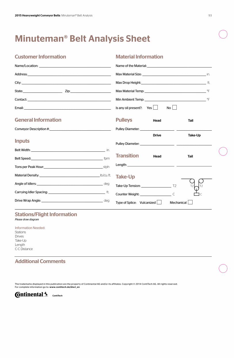
Minuteman® Belt Analysis Sheet
The trademarks displayed in this publication are the property of Continental AG and/or its affiliates. Copyright © 2014 ContiTech AG. All rights reserved. For complete information go to: www.contitech.de/discl_en
Customer Information
Name/Location: ______________________________________________________________
Address: ________________________________________________________________________
City: _____________________________________________________________________________
State: __________________________________ Zip: ___________________________________
Contact: ________________________________________________________________________
Email: ___________________________________________________________________________
General Information
Conveyor Description #: _____________________________________________________
Inputs
Belt Width: ________________________________________________________________ in.
Belt Speed: ______________________________________________________________ fpm
Tons per Peak Hour: ___________________________________________________stph
Material Density: ____________________________________________________________________ lb./cu. ft.
Angle of Idlers: _________________________________________________________ deg
Carrying Idler Spacing: _________________________________________________ ft.
Drive Wrap Angle: _____________________________________________________ deg
Stations/Flight Information Please draw diagram
Information Needed:StationsDrivesTake-UpLengthC-C Distance
Additional Comments
Material Information
Name of the Material: ________________________________________________________
Max Material Size: _______________________________________________________ in.
Max Drop Height: ________________________________________________________ ft.
Max Material Temp: _____________________________________________________ °F
Min Ambient Temp: _____________________________________________________ °F
Is any oil present?: Yes No
Pulleys Head Tail
Pulley Diameter: ______________________________________________________________
Drive Take-Up
Pulley Diameter: ______________________________________________________________
Transition Head Tail
Length: _________________________________________________________________________
Take-Up
Take-Up Tension: __________________________ T2
Counter Weight: ___________________________ C
Type of Splice: Vulcanized Mechanical
C
T2 T2
93 2015 Heavyweight Conveyor Belts Minuteman® Belt Analysis
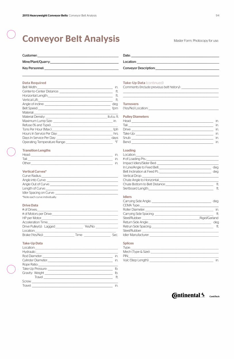
Conveyor Belt Analysis Master Form. Photocopy for use.
Customer: ______________________________________________________________________
Mine/Plant/Quarry:___________________________________________________________
Key Personnel: ________________________________________________________________
Data RequiredBelt Width: _______________________________________________________________________ in.Center-to-Center Distance: __________________________________________________ ft.Horizontal Length: _____________________________________________________________ ft.Vertical Lift: ______________________________________________________________________ ft.Angle of incline: ______________________________________________________________ degBelt Speed: ____________________________________________________________________ fpmMaterial: _______________________________________________________________________________Material Density: __________________________________________________________ lb./cu. ft.Maximum Lump Size: ________________________________________________________ in.Refuse (% and Type): _______________________________________________________________Tons Per Hour (Max.): _________________________________________________________ tphHours In Service Per Day: ____________________________________________________ hrs.Days In Service Per Day: ___________________________________________________ daysOperating Temperature Range: ____________________________________________ °F
Transition LengthsHead: _____________________________________________________________________________ in.Tail: ________________________________________________________________________________ in.Other: _____________________________________________________________________________ in.
Vertical Curves*Curve Radius: ________________________________________________________________________Angle into Curve: ___________________________________________________________________Angle Out of Curve: ________________________________________________________________Length of Curve: ____________________________________________________________________Idler Spacing on Curve: ___________________________________________________________*Note each curve individually.
Drive Data# of Drives: ____________________________________________________________________________# of Motors per Drive: ______________________________________________________________HP per Motor: ________________________________________________________________________Acceleration Time:__________________________________________________________________Drive Pulley(s): Lagged __________________________ Yes/No _____________________Location: ____________________________________________________________________________Brake (Yes/No): _____________________________ Time _________________________ Sec.
Take-Up DataLocation: ______________________________________________________________________________Hydraulic: _____________________________________________________________________________Rod Diameter: __________________________________________________________________ in.Cylinder Diameter: _____________________________________________________________ in.Rope Ratio: ___________________________________________________________________________Take-Up Pressure: _____________________________________________________________ lb.Gravity: Weight ________________________________________________________________ lb. Travel _________________________________________________________________ ft.Screw: _________________________________________________________________________________Travel: ____________________________________________________________________________ in.
Date: ____________________________________________________________________________
Location: _______________________________________________________________________
Conveyor Description: _______________________________________________________
Take-Up Data (continued)Comments (Include previous belt history): _______________________________________________________________________________________________________________________________________________________________________________________________________________________ Turnovers(Yes/No) Location: __________________________________________________________________
Pulley DiametersHead: _____________________________________________________________________________ in.Tail: ________________________________________________________________________________ in.Drive: _____________________________________________________________________________ in.Take-Up: _________________________________________________________________________ in.Snub: _____________________________________________________________________________ in.Bend: _____________________________________________________________________________ in.
LoadingLocation: ______________________________________________________________________________# of Loading Pts.: ____________________________________________________________________Impact Idlers/Slider Bed: __________________________________________________________In Line/Angle to Feed Belt: _________________________________________________ deg Belt Inclination at Feed Pt.: _________________________________________________ degVertical Drop: ________________________________________________________________________Chute Angle to Horizontal: ________________________________________________________Chute Bottom to Belt Distance: _____________________________________________ ft.Skirtboard Length: _____________________________________________________________ ft.
Idlers Carrying Side Angle: ________________________________________________________ deg CEMA Type: __________________________________________________________________________Roller Diameter: ________________________________________________________________ in. Carrying Side Spacing: _______________________________________________________ ft. Steel/Rubber: ______________________________________________________Rigid/Garland Return Side Angle: ___________________________________________________________ deg Retrun Side Spacing: __________________________________________________________ ft.Steel/Rubber: ________________________________________________________________________Idler Manufacturer: _________________________________________________________________
SplicesType: ___________________________________________________________________________________Mech (Type & Size): ________________________________________________________________PIN: _____________________________________________________________________________________Vulc (Step Length): ____________________________________________________________ in.
94 2015 Heavyweight Conveyor Belts Conveyor Belt Analysis
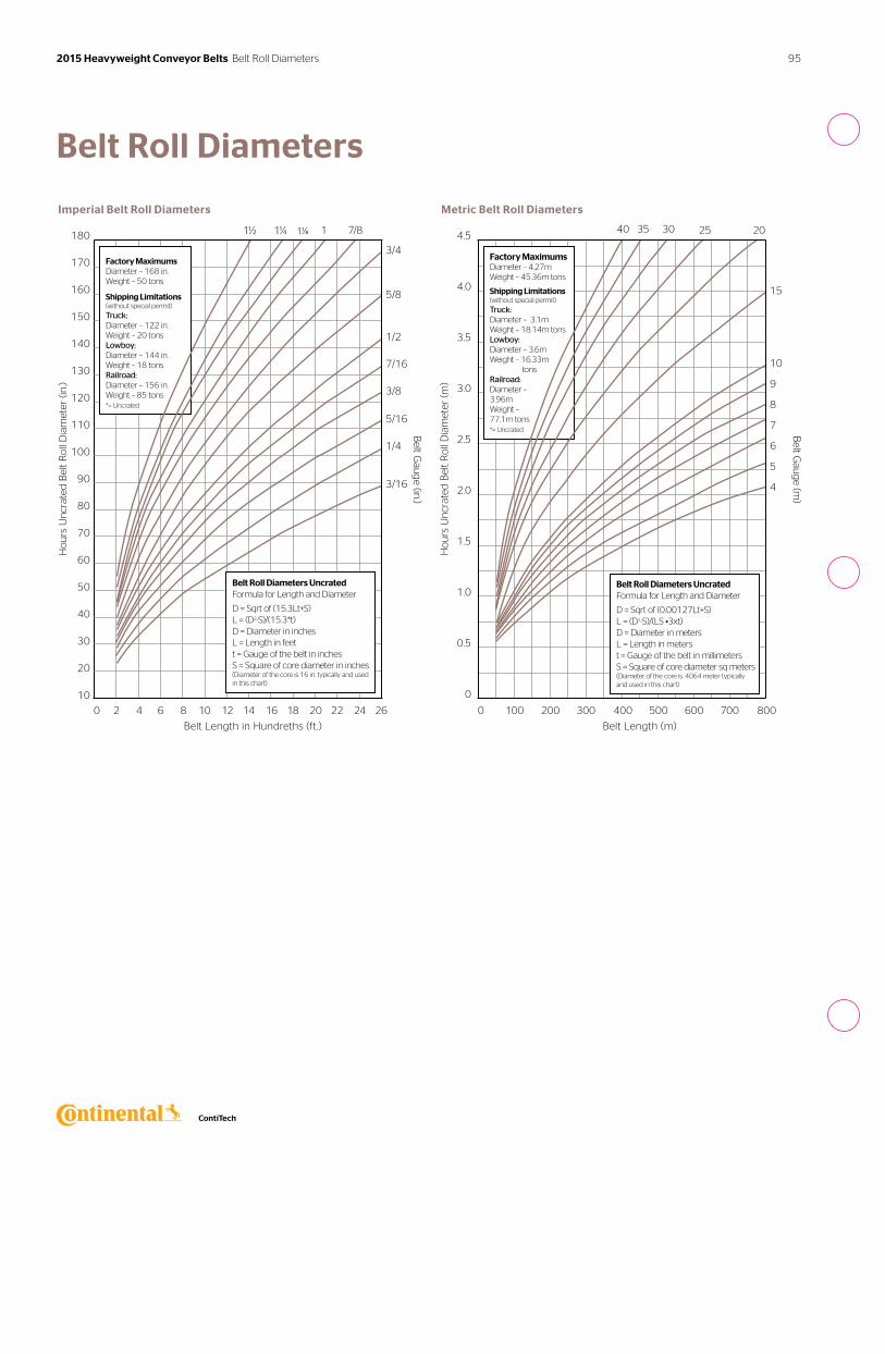
Belt Roll Diameters
0 2 4 6 8 10 12 14 16 18 20 22 24 26
Belt Length in Hundreths (ft.)
180
170
160
150
140
130
120
110
100
90
80
70
60
50
40
30
20
10
Ho
urs
Un
crat
ed B
elt
Ro
ll D
iam
eter
(in
.)
Belt G
aug
e (in.)
1½ 1¼ 1⅛ 1 7/8
Imperial Belt Roll Diameters
Belt Roll Diameters UncratedFormula for Length and Diameter
D = Sqrt of (15.3Lt+S)L = (D2-S)/(15.3*t)D = Diameter in inchesL = Length in feett = Gauge of the belt in inchesS = Square of core diameter in inches(Diameter of the core is 16 in. typically and used in this chart)
Factory Maximums Diameter – 168 in. Weight – 50 tons
Shipping Limitations (without special permit)
Truck: Diameter – 122 in.Weight – 20 tonsLowboy: Diameter – 144 in.Weight – 18 tonsRailroad: Diameter – 156 in.Weight – 85 tons*= Uncrated
3/4
5/8
1/2
7/16
3/8
5/16
1/4
3/16
0 100 200 300 400 500 600 700 800
Belt Length (m)
4.5
4.0
3.5
3.0
2.5
2.0
1.5
1.0
0.5
0
Ho
urs
Un
crat
ed B
elt
Ro
ll D
iam
eter
(m
)
Belt G
aug
e (m)
15
10
9
8
7
6
5
4
40 35 30 25 20
Metric Belt Roll Diameters
Belt Roll Diameters UncratedFormula for Length and Diameter
D = Sqrt of (0.00127Lt+S)L = (D2-S)/(LS •3xt)D = Diameter in metersL = Length in meterst = Gauge of the belt in millimetersS = Square of core diameter sq meters(Diameter of the core is .4064 meter typically and used in this chart)
Factory MaximumsDiameter – 4.27mWeight – 45.36m tons
Shipping Limitations (without special permit)
Truck: Diameter – 3.1mWeight – 18.14m tonsLowboy: Diameter – 3.6mWeight – 16.33m tonsRailroad: Diameter – 3.96mWeight – 77.1m tons*= Uncrated
95 2015 Heavyweight Conveyor Belts Belt Roll Diameters
Continental ContiTech and its affiliates offer a number of different terms and conditions for the purchase of materials, services and products and the sale of products depending on the location of the transaction. These may vary from time to time and for different product categories and locations. Please see our terms and conditions of sale at www.contitech.us. While every effort is made to keep these up to date, there may be discrepancies. If you have any questions, please ask for a copy of our terms and conditions when accepting or placing orders with us.
Continental ContiTech Quotation Provisions Terms and Conditions of Sale
96 2015 Heavyweight Conveyor Belts Quotation Provisions
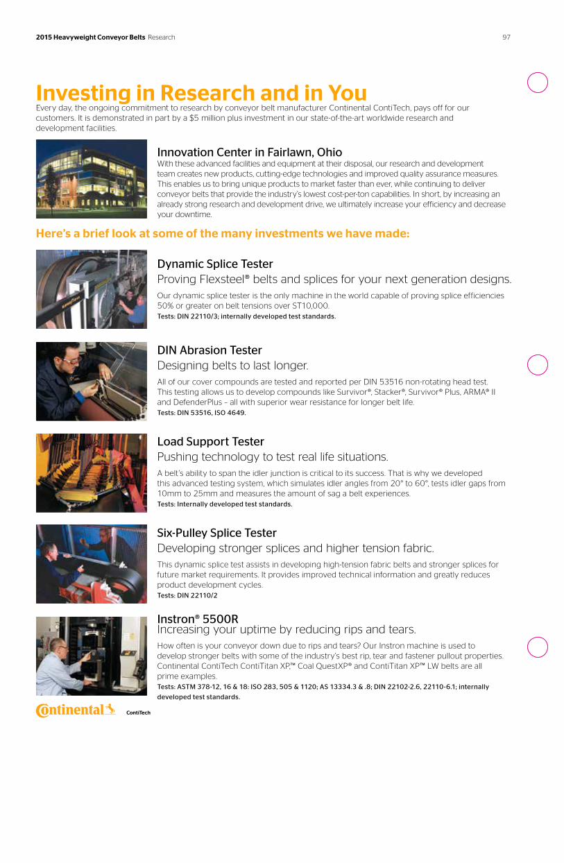
97 2015 Heavyweight Conveyor Belts Research
Investing in Research and in YouEvery day, the ongoing commitment to research by conveyor belt manufacturer Continental ContiTech, pays off for our customers. It is demonstrated in part by a $5 million plus investment in our state-of-the-art worldwide research and development facilities.
Innovation Center in Fairlawn, OhioWith these advanced facilities and equipment at their disposal, our research and development team creates new products, cutting-edge technologies and improved quality assurance measures. This enables us to bring unique products to market faster than ever, while continuing to deliver conveyor belts that provide the industry’s lowest cost-per-ton capabilities. In short, by increasing an already strong research and development drive, we ultimately increase your efficiency and decrease your downtime.
Here’s a brief look at some of the many investments we have made:
Dynamic Splice TesterProving Flexsteel® belts and splices for your next generation designs.Our dynamic splice tester is the only machine in the world capable of proving splice efficiencies 50% or greater on belt tensions over ST10,000. Tests: DIN 22110/3; internally developed test standards.
DIN Abrasion TesterDesigning belts to last longer.All of our cover compounds are tested and reported per DIN 53516 non-rotating head test. This testing allows us to develop compounds like Survivor®, Stacker®, Survivor® Plus, ARMA® II and DefenderPlus – all with superior wear resistance for longer belt life. Tests: DIN 53516, ISO 4649.
Load Support TesterPushing technology to test real life situations.A belt’s ability to span the idler junction is critical to its success. That is why we developed this advanced testing system, which simulates idler angles from 20° to 60°, tests idler gaps from 10mm to 25mm and measures the amount of sag a belt experiences.Tests: Internally developed test standards.
Six-Pulley Splice TesterDeveloping stronger splices and higher tension fabric.This dynamic splice test assists in developing high-tension fabric belts and stronger splices for future market requirements. It provides improved technical information and greatly reduces product development cycles. Tests: DIN 22110/2
Instron® 5500R Increasing your uptime by reducing rips and tears.How often is your conveyor down due to rips and tears? Our Instron machine is used to develop stronger belts with some of the industry’s best rip, tear and fastener pullout properties. Continental ContiTech ContiTitan XP,™ Coal QuestXP® and ContiTitan XP™ LW belts are all prime examples. Tests: ASTM 378-12, 16 & 18: ISO 283, 505 & 1120; AS 13334.3 & .8; DIN 22102-2.6, 22110-6.1; internally
developed test standards.
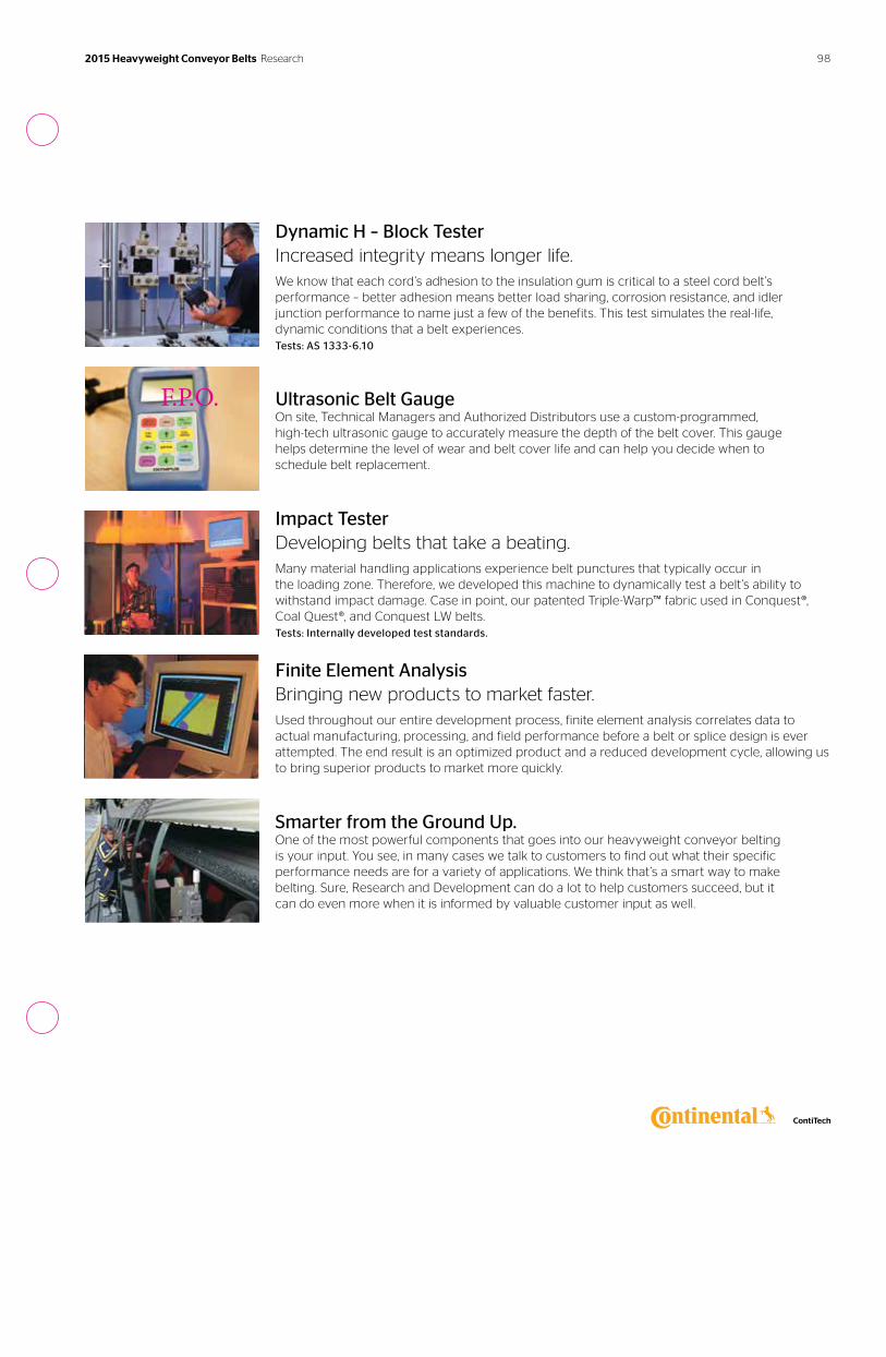
Dynamic H – Block TesterIncreased integrity means longer life.We know that each cord’s adhesion to the insulation gum is critical to a steel cord belt’s performance – better adhesion means better load sharing, corrosion resistance, and idler junction performance to name just a few of the benefits. This test simulates the real-life, dynamic conditions that a belt experiences. Tests: AS 1333-6.10
Ultrasonic Belt GaugeOn site, Technical Managers and Authorized Distributors use a custom-programmed, high-tech ultrasonic gauge to accurately measure the depth of the belt cover. This gauge helps determine the level of wear and belt cover life and can help you decide when to schedule belt replacement.
Impact TesterDeveloping belts that take a beating.Many material handling applications experience belt punctures that typically occur in the loading zone. Therefore, we developed this machine to dynamically test a belt’s ability to withstand impact damage. Case in point, our patented Triple-Warp™ fabric used in Conquest®, Coal Quest®, and Conquest LW belts. Tests: Internally developed test standards. Finite Element AnalysisBringing new products to market faster.Used throughout our entire development process, finite element analysis correlates data to actual manufacturing, processing, and field performance before a belt or splice design is ever attempted. The end result is an optimized product and a reduced development cycle, allowing us to bring superior products to market more quickly.
Smarter from the Ground Up. One of the most powerful components that goes into our heavyweight conveyor belting is your input. You see, in many cases we talk to customers to find out what their specific performance needs are for a variety of applications. We think that’s a smart way to make belting. Sure, Research and Development can do a lot to help customers succeed, but it can do even more when it is informed by valuable customer input as well.
F.P.O.
982015 Heavyweight Conveyor Belts Research
ContiTech. Engineering Next Level
As a division of the Continental Group, ContiTech
is a recognized innovation and technology leader
in natural rubber and plastics. As an industry partner
with a firm future ahead of us, we engineer solutions
both with and for our customers around the world.
Our bespoke solutions are specially tailored to meet
the needs of the market. With extensive expertise
in materials and processes, we are able to develop
cutting-edge technologies while ensuring we
make responsible use of resources. We are quick
to respond to important technological trends, such
as function integration, lightweight engineering
and the reduction of complexity, and offer a range
of relevant products and services. That way, when
you need us, you’ll find we’re already there.
The content of this publication is not legally binding and is provided as information only. The trademarks displayed in this publication are the property of Continental AG and/or its affiliates. Copyright © 2014 ContiTech AG. All rights reserved. For complete information go to: www.contitech.de/discl_en
Contact
ContiTech AG
NAFTA Headquarters
703 S. Cleveland Massillon Road
Fairlawn, OH 44333-3023 U.S.A.
1-800-235-4632
Canada
1-888-275-4397
FAX 1-888-464-4397
Mexico
1-800-439-7373
FAX 1-800-062-0918
Germany
+49 (0)511 938 02
www.contitech.us
20
15 H
eavyw
eigh
t Co
nveyo
r Belt C
atalog
20
78
171
8


![1 SERIES Belt Conveyor System B090 - Bett Sistemi Srl€¦ · CONVEYOR BELT DEVELOPMENT CALCULATION FORMULA Conveyor belt length = 300 + {[(L-94)-(2• Conveyor belt thick. )]•2}](https://cdn.vdocuments.net/doc/165x107/5ad3c4047f8b9a48398b7ae4/1-series-belt-conveyor-system-b090-bett-sistemi-conveyor-belt-development-calculation.jpg)