superior performance. powerful technology.
SuperPower Inc. is a subsidiary of Furukawa Electric Co. Ltd.
2G HTS Coil Technology Development at SuperPower Inc.
Honghai Song, Paul Brownsey, Yifei Zhang, Justin Waterman, Toru Fukushima and Drew HazeltonSuperPower Inc., Schenectady, NY 12304 USA
2JB-01, The Applied Superconductivity ConferencePortland, Oregon October 7-12, 2012
All Rights Reserved. Copyright SuperPower® Inc. 2012 ASC 2012 - Portland, Oregon - October 7-12, 2012 2
Outline
• 2G HTS coil development– General conductor / coil mechanical performance – Challenges in epoxied coils– Develop alternative approaches in coil winding and post‐wire‐
production• An example: high quality 2G HTS pancake coil developments
– Practices, winding, conductor splice, coil joint and testing• Other coil‐related areas
– Layer wound coils, alternative insulation• Conclusions

SuperPower’s wire exhibits robust mechanical properties
• Conductor mechanical properties can be characterized in three dimensions– ab plane along the length– ab plane along the width– Along the c‐axis direction,
perpendicular to ab plane• Mechanical properties are a function of
copper thickness and temperature
All Rights Reserved. Copyright SuperPower® Inc. 2012 ASC 2012 - Portland, Oregon - October 7-12, 2012 3
Conductor Stress‐Strain at RT, 77K and 4 K with Various Copper Thickness
W.D. Markiewicz et al. IEEE TAS, 22(3), 2012
(RT)40 um60 um
100 um
0
200
400
600
800
1000
1200
0.000 0.002 0.004 0.006 0.008 0.010 0.012
stress (M
Pa)
strain
Copper thickness
40 µm
60 µm
100 µm
Data from NHMFL
(77 K and 4 K)

Robust mechanical properties exhibited in 2G HTS coilsalong the width in ab plane
All Rights Reserved. Copyright SuperPower® Inc. 2012 ASC 2012 - Portland, Oregon - October 7-12, 2012 4
• Stress upon DPC coils up to 100 MPa, 77 K
• No observable change in critical current
• Repeat 100 timesW.B. Sampson et al., PAC11, NYC, March 28, 2011
(Brookhaven National Laboratory)
• Mechanical properties in 3D– ab plane along the length
Azimuthal direction– ab plane along the width axial
direction (z axis)– Along the c‐axis direction,
perpendicular to ab plane radial direction
r axis (c‐axis)
z axis (ab plane)

Robust mechanical properties along c‐axis (compressive)
All Rights Reserved. Copyright SuperPower® Inc. 2012 ASC 2012 - Portland, Oregon - October 7-12, 20125
Static Compression Test – Effect on Ic
r axis (c‐axis)
z axis (ab plane)
• RT compression, Ic tested at 77 K• No measurable degradation in critical current
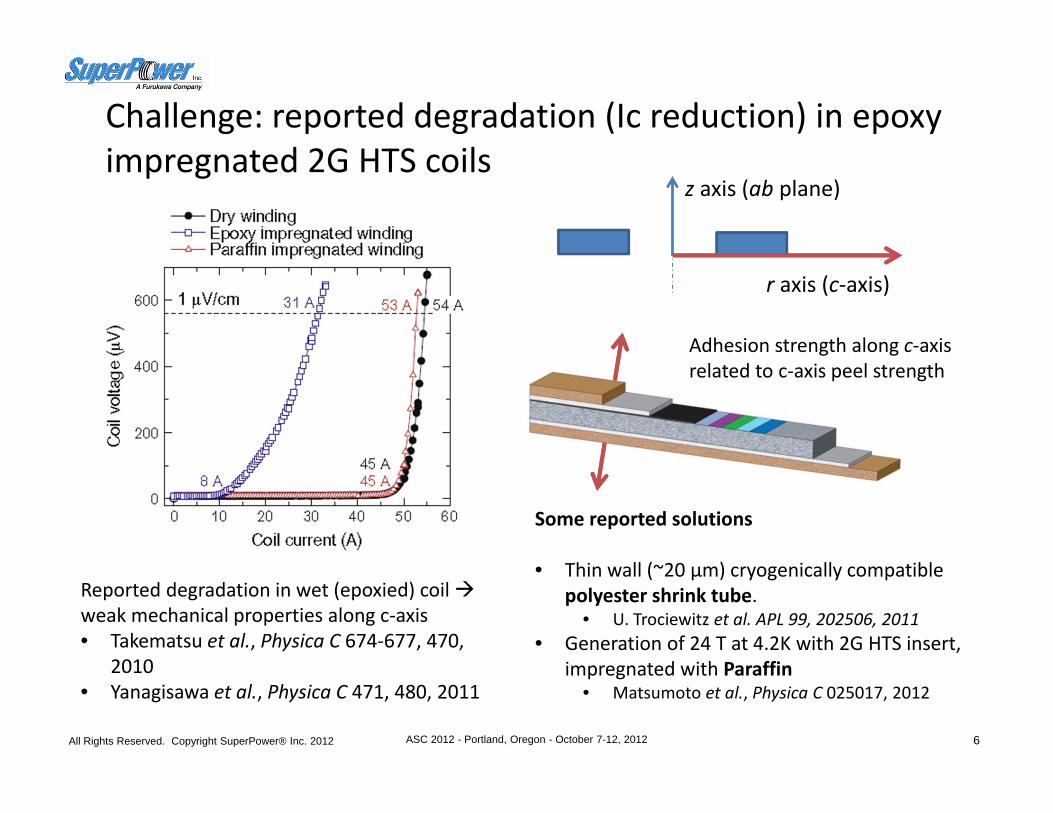
Challenge: reported degradation (Ic reduction) in epoxy impregnated 2G HTS coils
All Rights Reserved. Copyright SuperPower® Inc. 2012 ASC 2012 - Portland, Oregon - October 7-12, 2012 6
Reported degradation in wet (epoxied) coil weak mechanical properties along c‐axis• Takematsu et al., Physica C 674‐677, 470,
2010• Yanagisawa et al., Physica C 471, 480, 2011
Adhesion strength along c‐axisrelated to c‐axis peel strength
Some reported solutions
• Thin wall (~20 μm) cryogenically compatible polyester shrink tube.
• U. Trociewitz et al. APL 99, 202506, 2011• Generation of 24 T at 4.2K with 2G HTS insert,
impregnated with Paraffin• Matsumoto et al., Physica C 025017, 2012
r axis (c‐axis)
z axis (ab plane)

Addressing the degradation issue in epoxied coils
All Rights Reserved. Copyright SuperPower® Inc. 2012 ASC 2012 - Portland, Oregon - October 7-12, 2012 7
C‐axis peel strength & Coil Degradation
Defining Problem
C‐axis peel strengthMeasurement
Characterization& Analysis
Technical Solution(Wire Fabrication)
Technical Solution(Coil Development)
Approach #2:
Stronger wires, higher c‐axis strength from 2G HTS wire production
Approach #1:
Develop coil winding techniques to tolerate lower peel strength conductor (focus of this presentation)
Wire Delamination
Coil Degradation
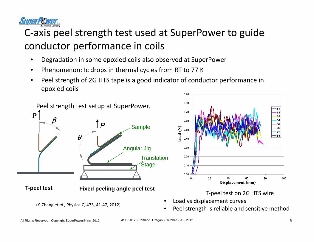
C‐axis peel strength test used at SuperPower to guide conductor performance in coils
• Degradation in some epoxied coils also observed at SuperPower• Phenomenon: Ic drops in thermal cycles from RT to 77 K• Peel strength of 2G HTS tape is a good indicator of conductor performance in
epoxied coils
All Rights Reserved. Copyright SuperPower® Inc. 2012 ASC 2012 - Portland, Oregon - October 7-12, 2012 8
(Y. Zhang et al., Physica C, 473, 41‐47, 2012)
P β
T-peel test
θ
Translation Stage
Angular Jig
SampleP
Fixed peeling angle peel test
• Load vs displacement curves• Peel strength is reliable and sensitive method
T‐peel test on 2G HTS wire
Peel strength test setup at SuperPower,
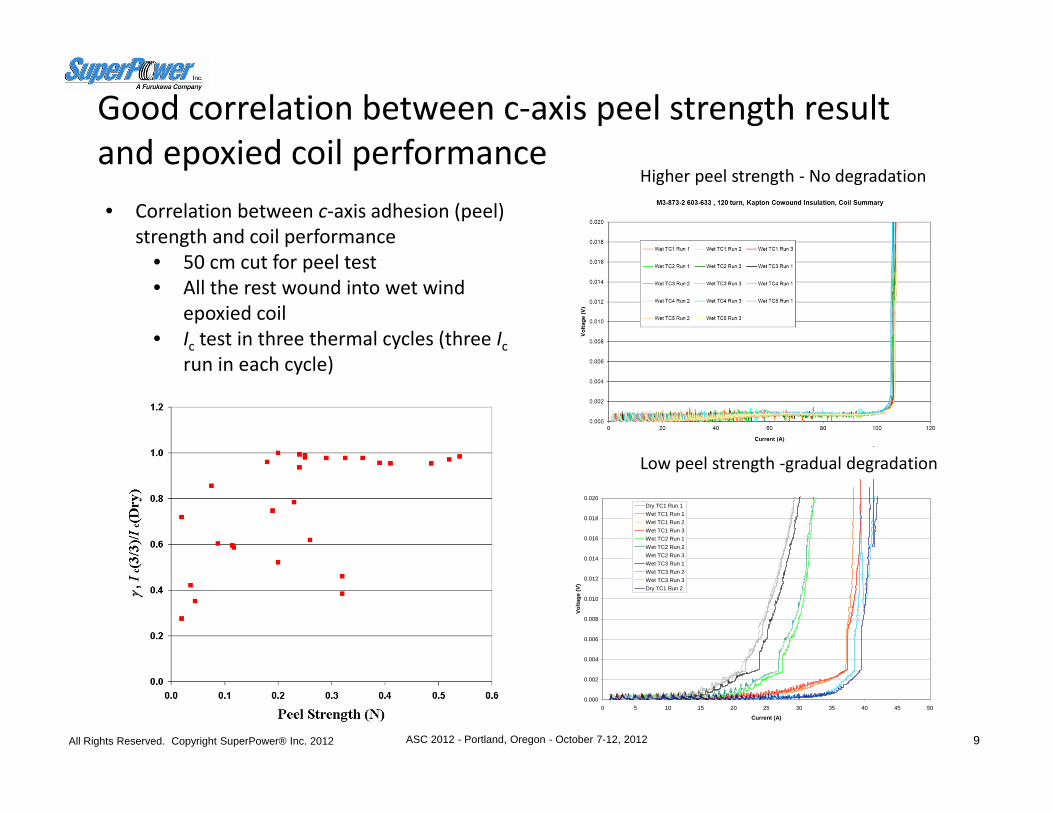
Good correlation between c‐axis peel strength result and epoxied coil performance
All Rights Reserved. Copyright SuperPower® Inc. 2012 ASC 2012 - Portland, Oregon - October 7-12, 2012 9
• Correlation between c‐axis adhesion (peel) strength and coil performance
• 50 cm cut for peel test• All the rest wound into wet wind
epoxied coil• Ic test in three thermal cycles (three Ic
run in each cycle)
0.000
0.002
0.004
0.006
0.008
0.010
0.012
0.014
0.016
0.018
0.020
0 5 10 15 20 25 30 35 40 45 50
Current (A)
Volta
ge (V
)
Dry TC1 Run 1Wet TC1 Run 1Wet TC1 Run 2Wet TC1 Run 3Wet TC2 Run 1Wet TC2 Run 2Wet TC2 Run 3Wet TC3 Run 1Wet TC3 Run 2Wet TC3 Run 3Dry TC1 Run 2
Low peel strength ‐gradual degradation
Higher peel strength ‐ No degradation
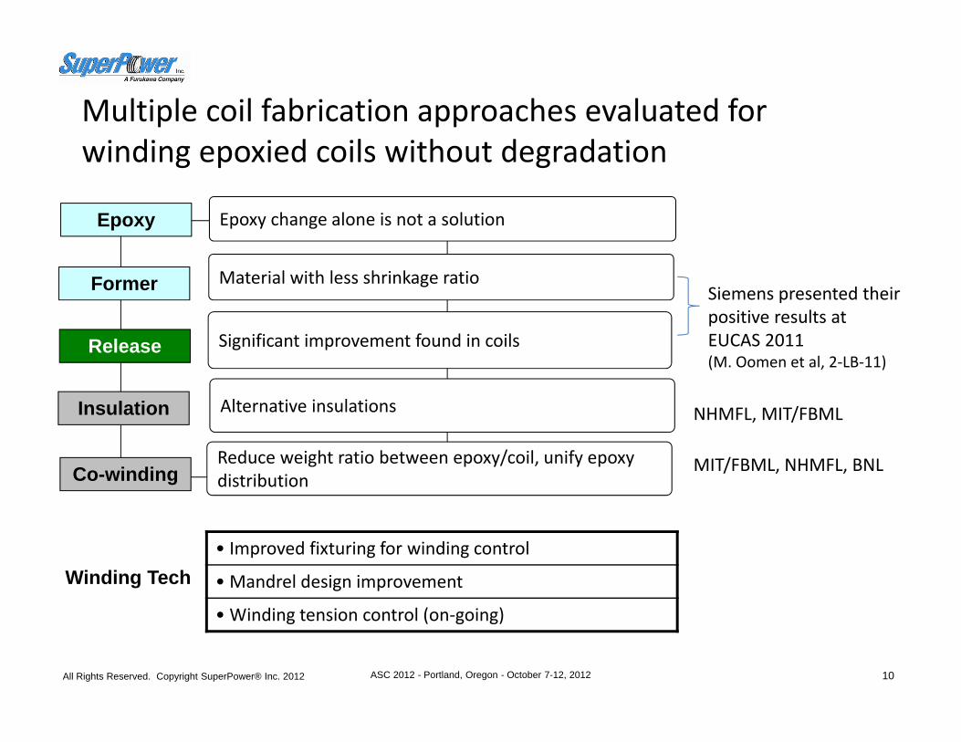
Multiple coil fabrication approaches evaluated for winding epoxied coils without degradation
All Rights Reserved. Copyright SuperPower® Inc. 2012 ASC 2012 - Portland, Oregon - October 7-12, 2012 10
Epoxy change alone is not a solutionEpoxy
Former Material with less shrinkage ratio
Release Significant improvement found in coils
Co-windingReduce weight ratio between epoxy/coil, unify epoxy distribution
Insulation Alternative insulations
• Improved fixturing for winding control
• Mandrel design improvement
• Winding tension control (on‐going)
Winding Tech
Siemens presented their positive results at EUCAS 2011(M. Oomen et al, 2‐LB‐11)
MIT/FBML, NHMFL, BNL
NHMFL, MIT/FBML
Metal strip co‐winding with HTS conductor for high field magnet has been effectively used by many groups• 1995, MIT/Sumitomo, SS co‐winding, 1G HTS Bi2223
– Generation of 24.0 T at 4.2 K and 23.4 T at 27 K with a high‐temperature superconductor coil in a 22.54 T background field
• APL, 67, 1923, 1995• 2003, NHMFL/OST, co‐wind SS (28 μm), 1G HTS Bi2212
– Development of a 5T HTS Insert Magnet as Part of 25T Class Magnets• IEEE Trans. Appl. Supercond., 13 (2), 1396‐1399, 2003
• 2011, MIT/FBML, co‐wind Cu (0.2 mm with one side polyester) for ReBCO, co‐wind SS (50 um) for Bi‐2223 – A 1.3 GHz LTS/HTS NMR magnet – a progress report
• IEEE Trans. Appl. Supercond., 21 (3), 2092, 2011• 2011, BNL, co‐wind SS or Kapton (25 μm), 2G HTS ReBCO
– High field HTS R&D soldenoid for Muon Collider• IEEE Trans. Appl. Supercond., 21, (3), 1884, 2011
• 2012, NHMFL, plain co‐wind SS, 2G HTS ReBCO– Superconducting 32 T magnet with ReBCO high field coils, NHMFL
• IEEE Trans. Appl. Supercond., 22 (3), 4300704, 2012
All Rights Reserved. Copyright SuperPower® Inc. 2012 ASC 2012 - Portland, Oregon - October 7-12, 2012 11
Pros and cons of SS co‐winding• Pros
– Mechanical reinforcement– Less contained epoxy, improvement w/r to cool‐down– Insulation may become stabilizer during transient/local quench– Increased thermal conductivity, compared to conventional insulation
• Cons– Ramping loss (low ramping rate, HTS larger thermal margin)– Current re‐distribution during quench (may need modeling for large
magnet)– Impact on current densityPartial epoxy impregnation offers positive results – Side applied, epoxy partially penetrated into turns, 30‐40% of epoxy
coverage for 4 mm wide wire– Seals the coil, protects it from moisture– Mechanically fixes turn‐turn and layer‐layer
All Rights Reserved. Copyright SuperPower® Inc. 2012 ASC 2012 - Portland, Oregon - October 7-12, 2012 12
All Rights Reserved. Copyright SuperPower® Inc. 2012 ASC 2012 - Portland, Oregon - October 7-12, 2012 13
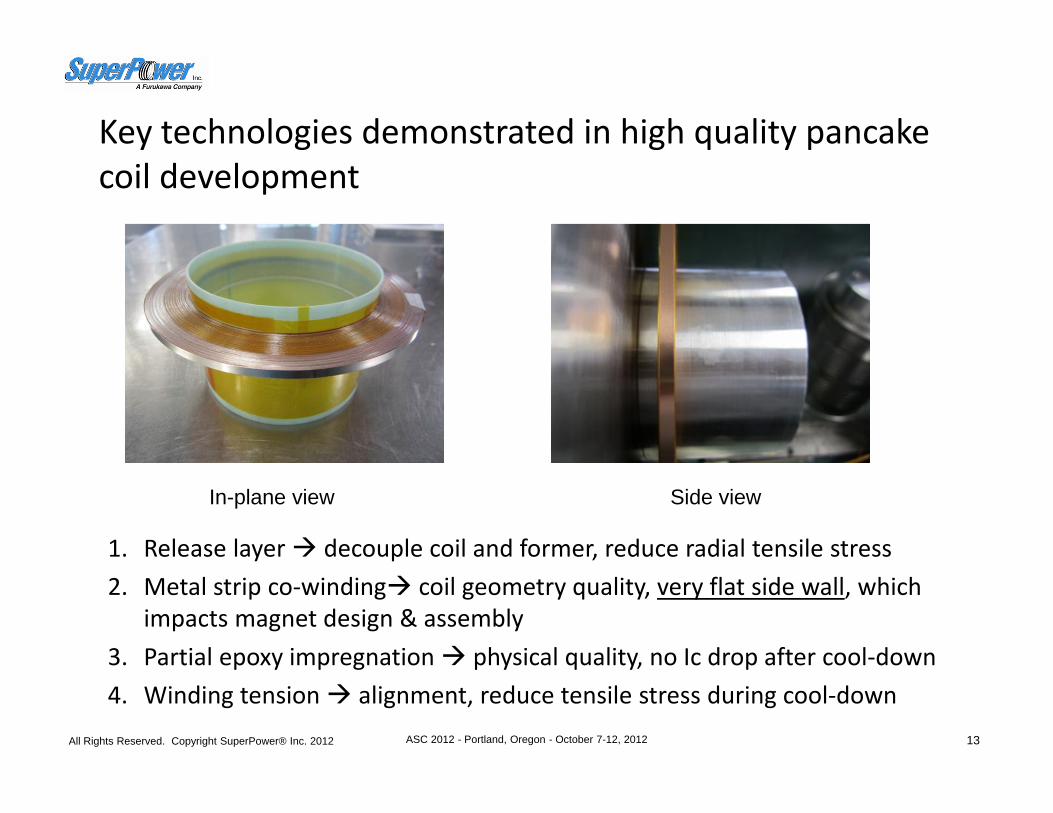
Key technologies demonstrated in high quality pancake coil development
1. Release layer decouple coil and former, reduce radial tensile stress2. Metal strip co‐winding coil geometry quality, very flat side wall, which
impacts magnet design & assembly3. Partial epoxy impregnation physical quality, no Ic drop after cool‐down4. Winding tension alignment, reduce tensile stress during cool‐down
In-plane view Side view
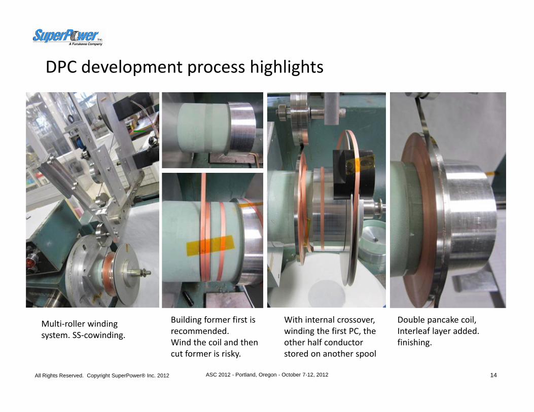
DPC development process highlights
All Rights Reserved. Copyright SuperPower® Inc. 2012 ASC 2012 - Portland, Oregon - October 7-12, 2012 14
Building former first is recommended.Wind the coil and then cut former is risky.
With internal crossover, winding the first PC, the other half conductor stored on another spool
Double pancake coil, Interleaf layer added.finishing.
Multi‐roller winding system. SS‐cowinding.
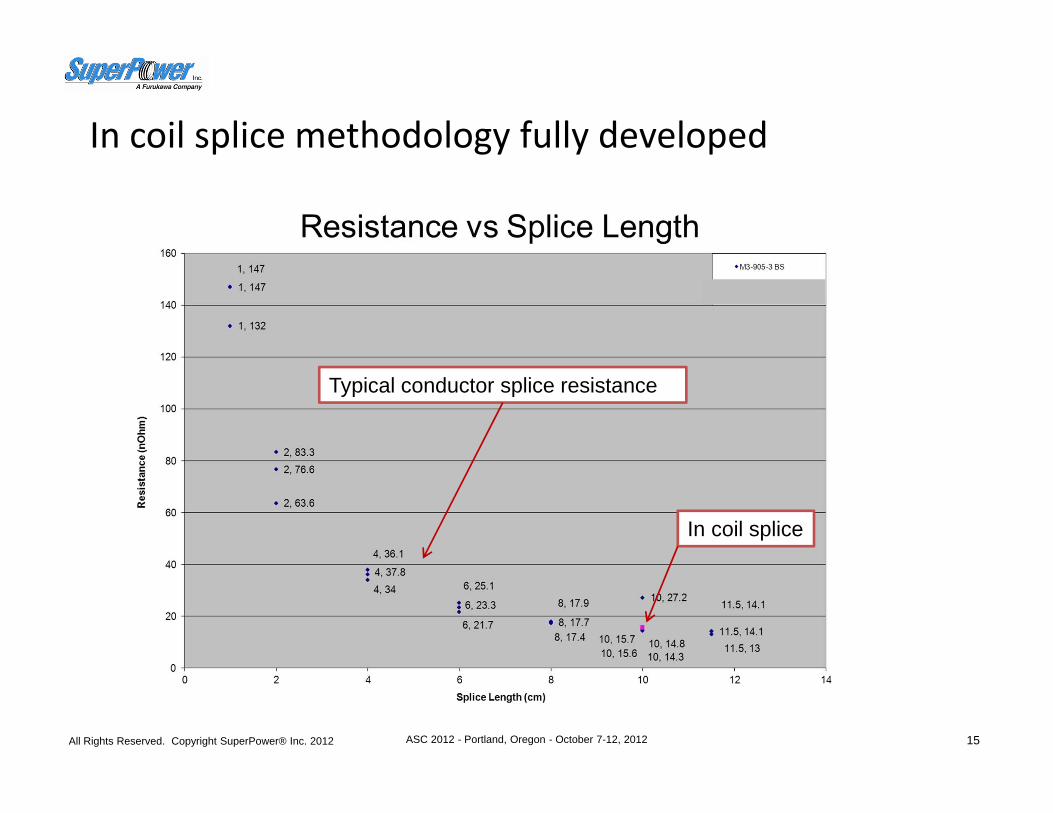
In coil splice methodology fully developed
All Rights Reserved. Copyright SuperPower® Inc. 2012 ASC 2012 - Portland, Oregon - October 7-12, 2012 15
Typical conductor splice resistance
In coil splice
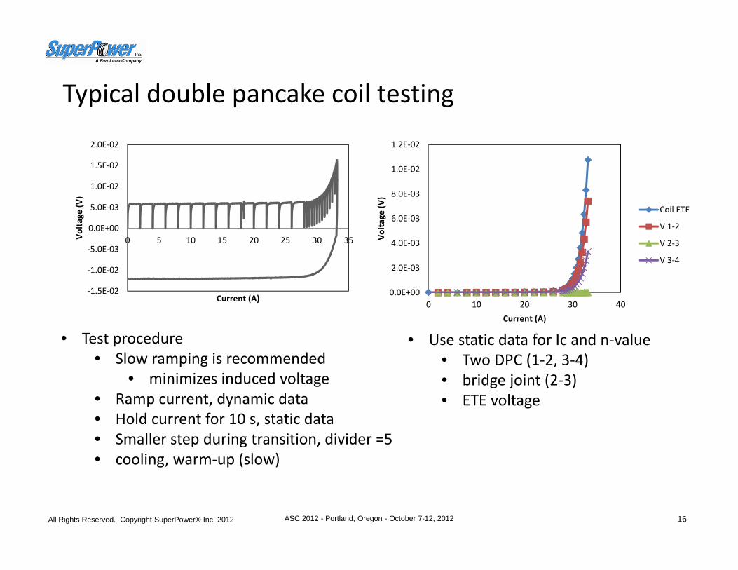
Typical double pancake coil testing
All Rights Reserved. Copyright SuperPower® Inc. 2012 ASC 2012 - Portland, Oregon - October 7-12, 2012 16
0.0E+00
2.0E‐03
4.0E‐03
6.0E‐03
8.0E‐03
1.0E‐02
1.2E‐02
0 10 20 30 40
Volta
ge (V
)
Current (A)
Coil ETE
V 1‐2
V 2‐3
V 3‐4
‐1.5E‐02
‐1.0E‐02
‐5.0E‐03
0.0E+00
5.0E‐03
1.0E‐02
1.5E‐02
2.0E‐02
0 5 10 15 20 25 30 35Volta
ge (V
)
Current (A)
• Test procedure• Slow ramping is recommended
• minimizes induced voltage• Ramp current, dynamic data• Hold current for 10 s, static data• Smaller step during transition, divider =5• cooling, warm‐up (slow)
• Use static data for Ic and n‐value• Two DPC (1‐2, 3‐4)• bridge joint (2‐3)• ETE voltage
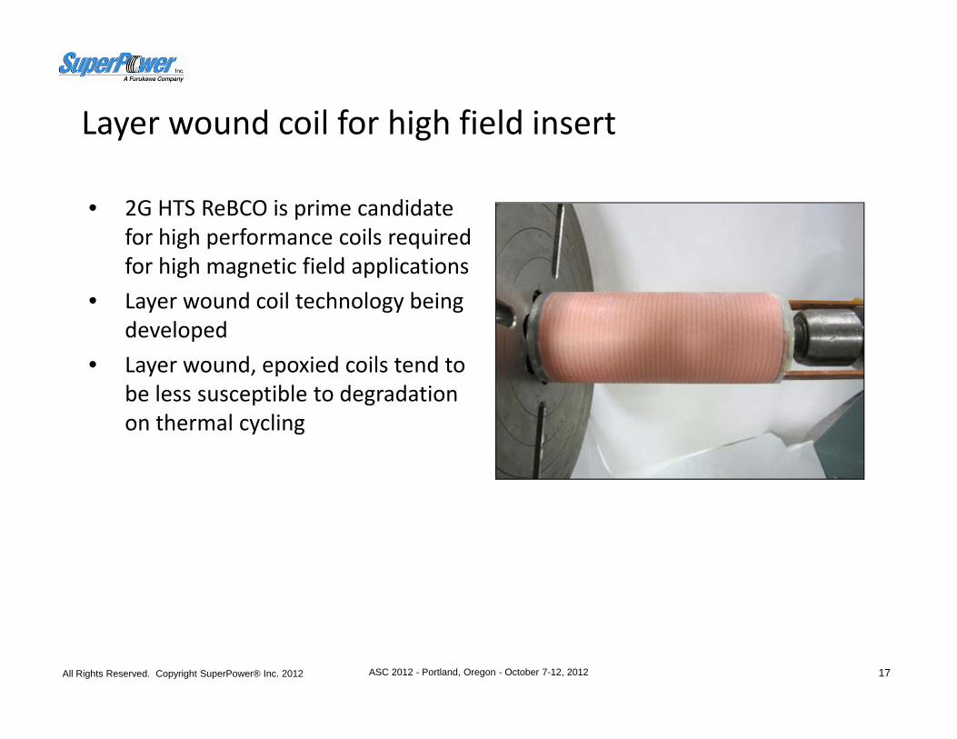
Layer wound coil for high field insert
All Rights Reserved. Copyright SuperPower® Inc. 2012 ASC 2012 - Portland, Oregon - October 7-12, 2012 17
• 2G HTS ReBCO is prime candidate for high performance coils required for high magnetic field applications
• Layer wound coil technology being developed
• Layer wound, epoxied coils tend to be less susceptible to degradation on thermal cycling
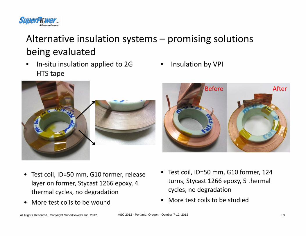
Alternative insulation systems – promising solutions being evaluated• In‐situ insulation applied to 2G
HTS tape
All Rights Reserved. Copyright SuperPower® Inc. 2012 ASC 2012 - Portland, Oregon - October 7-12, 2012 18
• Test coil, ID=50 mm, G10 former, release layer on former, Stycast 1266 epoxy, 4 thermal cycles, no degradation
• More test coils to be wound
• Test coil, ID=50 mm, G10 former, 124 turns, Stycast 1266 epoxy, 5 thermal cycles, no degradation
• More test coils to be studied
• Insulation by VPI
Before After

Conclusions
• Coil winding techniques in epoxied coils have been demonstrated that mitigate coil degradation on thermal cycling– An example of a successful DPC coil development
• SS co‐winding, epoxy side application• DPC coil winding• Developed a superconductor bridge joint between coils• Achieve good Ic and n‐value, no degradation found.
– The effectiveness of the partial epoxy side application technique to mitigate degradation of epoxied coils has been demonstrated.
• Dry wind , Partial wet wind (epoxy on coil edges) , Full epoxy coils (Wet wind, VPI) under development
• Coil geometries: Pancake → , Layer wound → , Racetracks next• Stronger conductor (high peel strength) being researched and developed
All Rights Reserved. Copyright SuperPower® Inc. 2012 ASC 2012 - Portland, Oregon - October 7-12, 2012 19


