< » •
ly Rofor Tot FO-2-1 January 13, 1980
Mcail Exploration 4 Producing U.S. Inc. Attentioni Mr. Jarry L. Horn* 12S0 Poydras Betiding Rev Orlaana* Louisiana 70113-1A92
Gantl
Roferonce la Made* to your In i t ia l Plan of Exploration aad Env.ronaontaI Roport rocelvod Otcanaor 50, 1987* for Loaso OCS-C 5801, Block 871, Eting Dana. Aroa. TMs plan tncleooa too activit iaa proposed for Mer.s A. B, and C.
In accordanco with 30 CPR 250.34, rev 1 aod Decos-ber 13, 1979, and oar lottor date* Janoary 29, 1979, this plan la ho rob y detemined to be complete end la nav being costs tdoroe for approval.
Your plen control cetlee and
r 1a M-J863 and should to reforoacod fn your concerning thia plan.
Sincerely yours.
(On*. Sgd.) A. Donald Giroir
$-
3m 0. J . Bourgeois Raglonal Superviaor f ield Operationa
beet Leaae OCS-G 5801 (OPS-3-2) (FILE ROON) /OPS-3-4 w/Publ1c Info. Copy of tho plan and ER (PUBLIC RECORDS)
MDJoseph:cck101/11/88:poocom
4
f
Mcbil Ex; -toration & Producing U.S. Inc.
December 22, 1987 Nf W ORLEANS WviSON
NfWOBlf ANS LCXH«1ANA W J I
Department of the I n t e r i o r Minerals Management Service 1201 Elmwood Park Boulevard Nev Orleans, LA 70123-2394
Attn: Regional Superviaor Fie ld Operacions FO-2-1
7.40.00.00 PLAN OF EXPLORATION OCS-G-5801 EWING BANK BLOCK 871
Gentlemen:
«%, HLLO /
Mobil Exploration and Producing United States (MEPUS), as agent for Mobil Oil Exploration & Producing Southeast Inc. (MOEPSI), submits for your approval a Plan of Exploration for Ewing Bank Block Ml (OCS-G-5801).
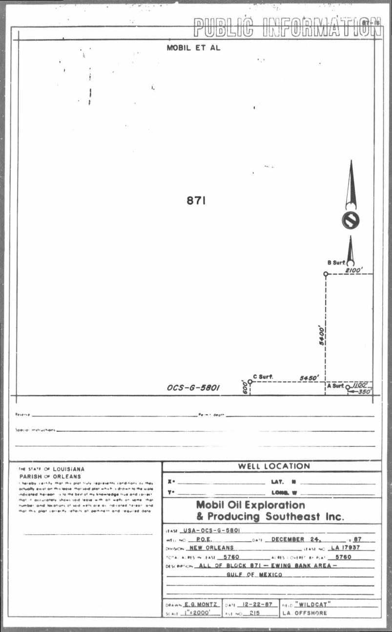
Three (3) wildcat wells are proposed to test the Middle Pleistocene to Lower Pliocene Sands. The proposed locations and depths are as follows:
Weill Location A (EV Blk 871)
Location B (EV Blk 871)
Location C (EV Blk 871)
Surface Location 350' FSL
1100' FEL
5400' FSL 2100* FEL
600' FSL 64501 FEL
Bottom Hole Location TVD (See Attached Geologic Program)
(See Attached Geologic Program)
(See Attached Geologic Program)
The following attachments provide additional details of the Plan of Exploration:
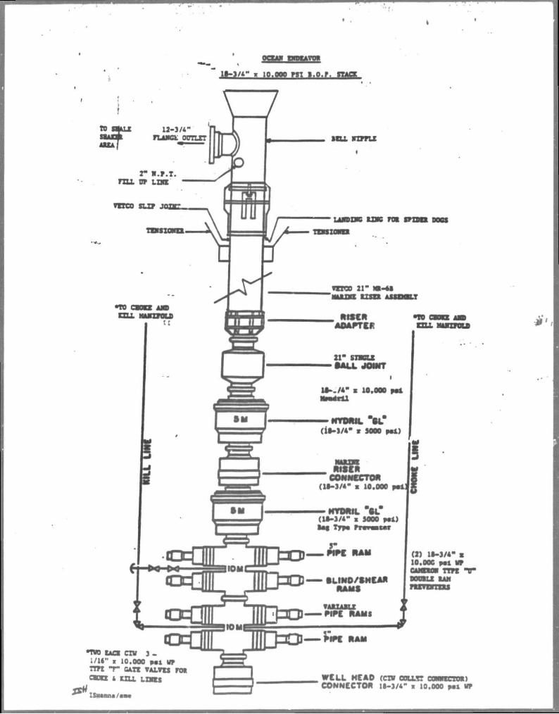
1. Exploration Plan and Geologic Program. 2. Structure Map of Middle Pleistocene. 3. Map of Top Abnormal Pressure. 4. Shallow Hazard Statements. 5. Shoreline Proximity Plat for Ewing Bank Blk 871. 6. General Mud Products List. 7. Specifications of the Semi-submersible Rig, Ocean Endeavor. 8. Environmental Report which Includes a Coastal Zone Consistency
Certification and an Air Quality Report. 9. Copy of request for publication of Public Notice of Federal Constimetion
review in the Baton Rouge State Times.
-2-
The current rig schedule calls for drilling to commence on Ewing Bank Block 871 Lojcatlon A on March 1, 1988. MEPUS anticipates that each well will requite approximately 60 days to d r i l l , thus a total of 180 dava will be required to complete operations outlined in this plan.
Drilling operations w i l l be serviced from MOEPSI's baae in Venice, LA. No additional personnel or expsnslon of this existing base will be required.
MOEPSI's latest Oil S p i l l Contingency Plan, as required by OCS Order No. 7, wes approved on July 13, 1987. Equipment maintained by the Clean Gulf Associates (CGA) will be available to support the drilling activity described in this exploration plan. The closest CGA base to the subject lease is located in Grand Isle, LA. Deployment time for s p i l l equipment to the location is approximately 18 hours.
I f you have any questions or comments regarding this Plan of Exploration, pleese contact me at (504) 566-5773.
Youra very truly,
Terry L. Horne Sr. Environmental & Regulatory Engineer
JLH/cal ERA3044A
i * »TA»» o* LOUISIANA
PARISH O* ORLEANS 1 N « ' » b » « • " •» • *>•• * • ! p<Oa H » I H M | t*Mtf>*>«»« A i »K#»
•••*• *»•% •*<>»• **0' O'O' m*«* % # » • • • >o M M •*4><m*9m *o-m—- » 'o «»• b»«> o» k"o»<«dg« ••«,• <•••••• *»«o' • o . . - ' o ' « ' » >»>o-> i o d t a n • • * a " o - MJ—« • * # •
• y « « b « ' o « d k » o ' o " v o ' M > < I » t ' H <>•• o . ' •<*•<>••« • ' w i
•tvo- *>•% PK»> ( • • • • • « • • • • ! • . •% a' p # * . » « ~ « o - d • « * < < • « l o ' o
WELL L O C A T I O N
LAT.
Mobil Oil Exploration & Producing Southeast Inc
M M U S A - 0 C S - 9 - 8 8 0 I
BQ.E, PCCCMICR 81-, w-. HEW ORLEANS
• C ' * • t n * , MSI 87SQ
«1L LMM NC LA I7S87
• f t r •• >,r S7S0
ALL Of BL&CK 171 - LWIWfl SANK AREA ~ aULrL^e„fcl£XjCJJ
oo**- E.Q. MONTZ «.i l"«2Q00'
I2-22-B7 mi »o 218
•t.r WILDCAT LA OFFSHORE

0 t « •
V « * — '**wv*4% *»«<
• o fro;
*l*'OS 04-Lmm WPO'it iS'
POSrtD I D£C. 83
MASTER 5H££T
IN COLE OE MEXICO
EWING BANK AtfEA
BLOCK an DATE §-13-93
mtoe'L OIL t*nO*ATiON 3 P*OOUClNG SOUTHCMST INC
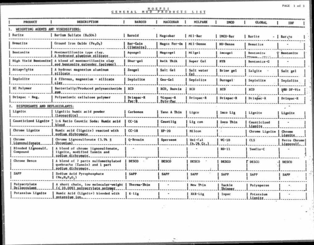
H O E P S ! C E M E S A L M U D P » T T p U C I S L I S T
PACE 1 of J
| PMOUCT | DU .CRIPTION | BAROID | KACCOBAR | HILPARK 1 IMCO I GLOBAL 1 1ST 1 i. uticirriNc n a m or VISCOSIFIERS:
1 Barite | Serins) Sulfate (BaSf*) I Baroid I Magcobar | Nil-Ser I IHOO-ier I Barite - | t a m e 1
i Ite
Benton i te
I Ground I r o n Oxide ( F e , 0 , ) I B a r - C a i n I Nagco F e r - O * I M i l -Dense
LlIltiBttll I I I Mont e o r l 1 l o n I t e t y p * c l a y . I Aquagel I Magcogel | M i lge l
l . f i . b X d c i K f d . i l w l O W . l U l S I K f I I I
I m g h Y i e l d B e n t o n i t e | A b lend o f • o n t n o r t i l o n t t e c l a y I S h u r - g e l I kwik T a l k I Super C o l
1 l.f«4.tosi9sltt.uttasSK.lNliitci 1
I NU-Dense
1 I
. i . B O t f . B f f O L f f O U C . C B t C O d C K . l N l r f t l l .
A t t a p " l * l t c
| kwik I k i k
J S e l t C e l | S a l t watei
l .Cf l
I S e p i o i i t e | C e o - C e l J S e p i o i i t e
| XC Polymer I B a c t e r i a l l y / P r o d u c e d p o l y a a c c n a r i d e | XCD | XCD, Duovls | XCD
| Dr lapac - B e g . I P o l y a n i o n i c c e l l u l o s e p o l y e e r | D r i s p a c - R I O l i p a c - R I D r l s p e c - R
1 1 l-ftsrlT. l.rslx:rK I
j Sepioiite
I" I | S r l n e g e l
| Durogel
| XCD
| D r l s p e c - R
t l i e
B e n t o n i t e
B e n t o n U e - C
L I | B e n t o n i t e j Benton i te |
j Salglte L : 1 I Salt gel
| Sepioiite j
J XCD | XtD DP-Vis
| Drlspec-R J Drlspec-R
I Sepioiite
2. DISPERSANTS AMD DEFLOCCULANTS:
Carbonox
I.
I L i g n i t e | L i g n i t i c b u a l c a c i d powder I
1 M k f O T I C i U f s 1
| C a o o t l c l c e d L i g n i t e • 1:4 R a t i o C a n e t l c Sods : Music a c i d | C C - I A
I - l.llffPs I Chrone Lignite I Rualc acid (l ignite) reacted with 1 1.tPSlWl.fllCtlCgtttt | Chr I . | Blsndcd Lignosulf. I A blend of cbroae 1ignoaulfonate, | Cowpound I lignite, nodlfled Tannin snd 1 1. itfdist.lltbigpstt
j Tar.n A Th in j L i g c o I loco Lig I Lignite I Lignite
I Lig con
Ml Icon
| Canstlig
| CC-18 | XP-20
Chroe* 1 Chrone L l g n o t u I f o n a t e ( S . S b 1 j Q - B r o x i n I Spersene 1 U n i - C s l U m i u l f P M t t l -Cbinivvi I I l . l i .5 fs .Ci . l .
15 :o Thin J. Causticized U n l i t . . . .
Chroe* L l g n l t
1
PC-10
•D-l l
CLS
T e s i f l o - C
I :.L2 I
Ch units
F e r r o Chr
U m i u l f -i L; i | Chroe* Desco | A b lend of 7 p o r t s s u l f o n e t h y l s t e d | DESCO
| quebracho (Tann in ) snd 1 p e r t
1 i.lPtlilff.41SblffMKff.
DESCO I DESCO
1 I DESCO
I SAFE I Sod iun A c i d Pyrophosphate | SAFE | SAFE | I I ( N s . N . P . O , ) | | |
I P o l y a c r y l a t e I A s n o r t c h a i n , low s w l e c u l e r - w e l g b t I Therma-Thln I I I . D c a K C S l S S t L l ^ l O . O O g i . D g l y i c n l g t g . o g l r t e c | 1 1
| Potass ium L i g n i t e I Hunlc A c i d ( L i g n i t e ) b lended w i t h I K - L i g I I ]
1 1-KldltlUff.lQOa.. 1 1.
SAPP
New T M a
I SAFE
T DESCC
i | SAPP
I
I DESCO
I SAFE
I I T a c k l e
l . l i lootc. | Inpac
P o l y s p e r s e J F o t s s s l u a U c o U f . . .
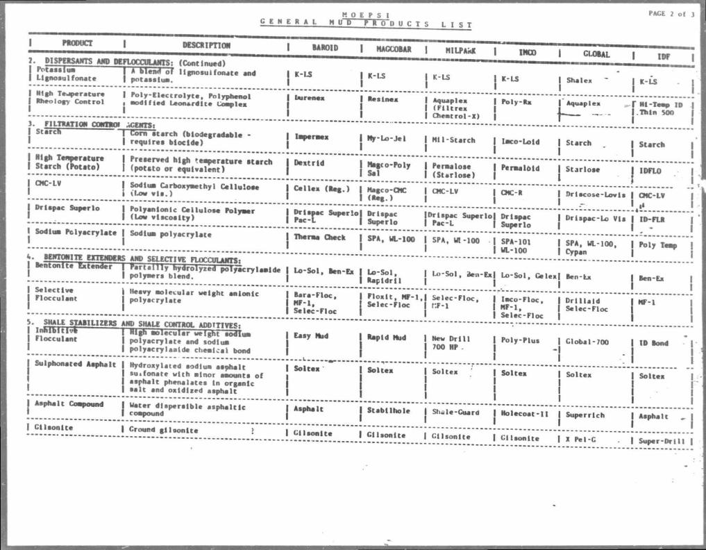
K O E P S 1 C E N E R A L M U D M O D U C T S L I S T
PACE 2 of
I PRODUCT I DESCRIPTION
I DISPERSANTS AND PCFLOCOIlAlfTS: (Continued)
BAROID 1 MACCOta 1 MILPAnf | IMCO | CLOtAL | IDF
I f j t " , l w I A bland or lignosulfonate snd I K-LS I r - i e , M c j Ut«o«ulfonste j potssslusi. | | K LS j K-LS j K - L S j Shalex ~ j K - £ s
I Nigh Temperature | Poly-Electrolyte. Polyphenol " " I T " " " " " " ' . Rheo.ogy C o n t r o l , s h i f t s * L e o n l r d l t e t S ^ U m j R - f " | f Aou.p l e« F M l - T e a .
j j j ^ r l l - g ] | f — — j.ThlnSOO FILTRATION CONTROI ..CENTS:
StarcTi [ ^ r S ^ ^ ^ - j 1 ™ | * " * ' I H I I -S tsrch l i s x o - U l d , s t . r c h . , s tarch
j Starlose I IDFLO
I WL-100 | Cypan
Sodli
I } • BEWOIIllE EITEMDERS AMD SELECTIVE FLOCCULANTS?
I Selective j Heaey molecular weight anionic
| L o - S o l , Ben-Ex I Lo-Sol, | L o - S o l , den E x | L o - S o l , C e l e x | Ben-Ex j Ben-Ex
MF-1 , | S e l e c - E l o c j S e l e c - F l o c , f.F-1
1 I n c o - F l o e . | H F - l ,
Dr i 1 l a i d S e l e c - F l o c 1
} • SHALE STABILIZERS AND SHALE CONTROL ADQTTIVES: I n n i b l t l * N i g h oo lecu l . r weight sodiua
j Flocculant | polyacrylate snd sodiun I polyscrylaalde chealcs l bond
I Essy Nnd I Rapid Hud | New D r i l l I Poly-Plus | Global-
i "I 700 I ID
I Soltoa I Soltex I Soltex I Soltex
I Asphalt Compound I Uster d l .pe rs lb le asphal t ic T a a m t e l t ! ! . ! ! ? P ^ ; ? , , I I S t - b i l h o 1 * | S n « « « - 0 " r d Molecoat-II I Superrlch | Asphslt
I Gilaonite | Ground g i l a o n i t e > I c i l l n a i r . ! !
- : Li™!!! L™!2 l u 1 * P e l c •supsr-onu
I Soltex I Soltex
Sulphonated Asphalt | Hydroxylated sodiua aaphait j su.fonate with nlnor amount• of I asphslt phenslstes ln organic
sslt snd oxidised esphal
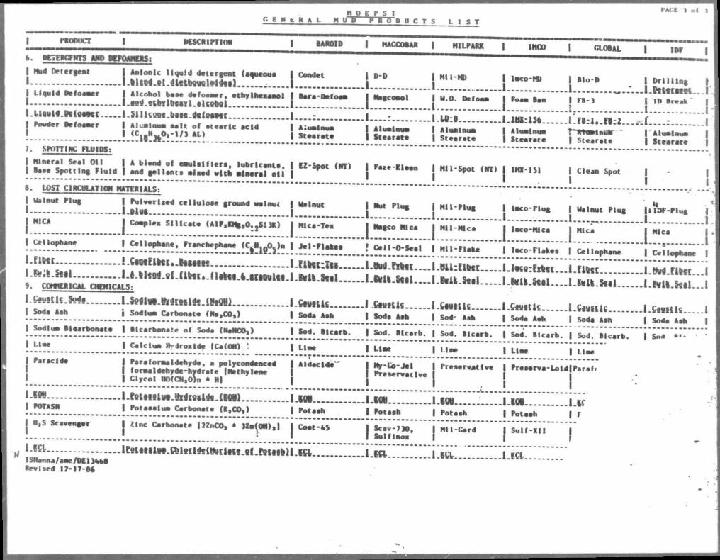
C E W E H A L H U P H O D U C T S L l S T
PAC.». ) of
Nud Detergent | A n i o n i c l i q u i d d o t c r g c n t (aqueous |
l.llciri.9f.«Uti«Kltl«f« m | L i q u i d D i f o M t r I A lcoho l bate d e f o - a e r , c t h y l h c a a n o l I
l.iod.utalPtul.flUeMi j l i f l w M . l r l l p p f M l I . S I l I C M M . P t N . M f p t a n c I
Powder Defoaaer | Al . e t n u a • • I t o f s t e a r i c a c i d I I ( C j . H ^ O . - l / j AL) |
SPOTTIWC FLUIDS:
Mineral S e a l O i l | A b lend of ea ju lo l f l e r s , l u b r i c a n t . I Base S p o t t i n g F l u i d | and g a l l a n t s n l a a d u i t h a l n e r a l o i l I
Condet
B e r a - O e f i a e r a - D e f o e a j Magconol | H.o. Defoaa j Foaa ban
S t a a r a t a
t Z - S p o t (NT)
| D-D
I j Magconol
I....: I A l u a l a u a I S t a a r a t a
| F a t e - K l e e n
| N I I -ND
I H.O. Daf<
I lnco-ND
.1 Foaa ban
l-Mf:l I A l u a l n u a I S t e a r a t e
LiWkitt..
I S t e a r a t e
I N i l - S p o t (NT) | IHI -151
F l : i . . F | : 2 T~Ttttn»li»uar
S t e a r a t e
C l e a n Spot
B l o - D
FB-3
I D r i l l i n g
I.Ptucttot F B - 1 | ID Break '
Zl. . . . L _ . . : I A l ua l nua I S t e e r e t e
. LOST CIRCULATION MATE*i ALS:
Walnut F l u g | P u i v e r l r e d c e l l u l o e e ground walnut I 1-BlUB |
H , c * J couple, sulcata (AiFaH%,o.2s:3ic)
I Cellopbane, Prancnephene ( C ^ o j j n |
"Hr l.cjMriHi..hSMH ".......'.A -fc-LStgl •-• feUo^wlJlbtl. Urtti.e.irgould.i • CONNCtlCAL O B P I l C a L S :
C w t U S . S o d g l . ^ l W . ( h ^ f f l l d e . ( N « O H l |
? " * > Sod iun Carbonate ( N s , C O s )
Sodiua t l e e r b o n a t e | B i c a r b o n a t e of Soda (NaHCO,)
L i n e
Far ac Ide
ION POTASN
I I ,S Scavenger
-tft S H a n n a / a e c / D C I M a g
Rev ised 17-17 86
I C a l c i u a Rvdroa lde (Ca(OH) !
j P a r a l o r a a l d e h y d e , a po I yconsented j f o m a l d e h y d e - h y d r . t e |Methy lenc I Glycol NO(CM,0)n • H)
Walnut
Mica-Tea
Jel-Flakes
riHciTti... Mll.SttL..
Ctvtlls
Soda Aan
Sod. Bicarb.
Line
Aldacide"
J Hut F l u g J M i l - P l u g
| Magco Mica | Ml I -M ica
f C e l l - O - S e a I | HI I - F l a k e
J.tt1h1.rz%tI....I.Hil:fiH[... J.»fU.eti l . . . . l .NU.SttL..
.1 CwiUs I.CtatUC I Soda Aah | Sod' Ash
I Sod . B i c a r b . | Sod. B i c a r b .
I U e e | L i n e
I - ttttt11*1 .HltlQllde . (Mil | . I Po teeo lun Carbonate ( K , C O , ) |
| Z i n c Carbonate | ? Z n C O , • U u ( O M ) a | |
I t t l t t l l W . f l i l p c l d e i H ^ c l a t c . g t . t ^ i g f h H
101 Potaah
C o a t - 4 $
M y - U - J e l P r e t e r v a t I v e
. L M | FotaeM
P r e s e r v a t i v e
.i.m.... I F o t a s h
S c a v - 7 1 0 , S u l f I n o i
I l a c o - P l u g
| I a c o - H l c a
I l a c o - F l a k e s
.l.lm:ts%tt...
. L M l . R u L . . .
.LCtviUs I Soda Ash
I Sod. B l c s r b .
I Llee
I P r e s s r v s - L o t d
Lm | Potaah
I Sulf-XI I
Walnut F l u g
H i e s
ItlOF-Flug | 1 1
IT. I Cellophane
.rati
-NU.fttl...
.Cmtls
Soda Ash
Sod. B l c s r b .
L l e e
F e r a l *
If r
I C e l l I
.i.tM.rittc...i
. l .M l .kaL . . I
LCttttlfi I | Sods Ash |
| N i l - C a r d
-*ft Lift LKL ]]]]]]]]i]ift]].].".]]
I tVl /4" « 10.1100 W I l .Q.P .
to SMALI 12 siArf ruui Mtt
- J / 4 " f l IMQ 00TLX?
r M.F.I F H L OF LIKE
7TTC0 SLZF JOflEL
•TO
ISfWoaa/
"TOO EACS CIW | . l / l i " i 10.000 M l UF TTFl "F" GATE VALVES FOI
A KILL LIHTS W C L L HCAO (CIV COLLI? C0MMK10B) CONNECTOR 18-3/4" s 10.000 psi UF
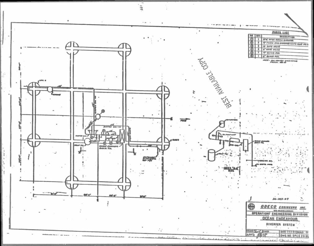
l o i n Muai»u«r
^ !
* •• i • • •• .
1 • P t t U i IOW ENCINECftlNC Ol VISION
QCtrVl f Mfrf AYOIHL oivintfft t u n . '
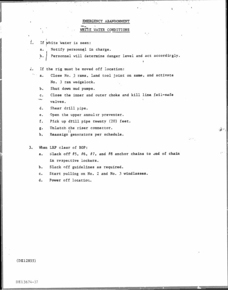
EMERGENCY ABAWDOHMEKT
WHTTE WATER CONDITIONS — ^ — — — — — — — — — —
• t. If white water is seen:
a. Notify personnel in charge.
b. | Personnel will determine danger level and act accordirgly.
2. If tha rig must be coved off location:
a. Close No. 3 rams, land tool j o i n t on sane, and activate
No. 3 ram wedgelock.
b. Shut down mud pumps.
c. Close the inner and outer choke and k i l l line fall-safe
valves.
d. Shear d r i l l pipa.
e. Open the upper annulir preventer.
f. Pick up d r i l l pipe twenty (20) feet.
g. Unlatch the riser connector. t(
h. Reassign generators per schedule. 3. When LRP clear of BOP:
a. Slack oft? #5, #6, #7, and #8 anchor chains to and of chain
in respective lockers.
b. Slack off guidelines as required.
c. Start pulling on No. 2 and No. 3 windlasses.
d. Power off location.
(DE12855)
DE13674-37
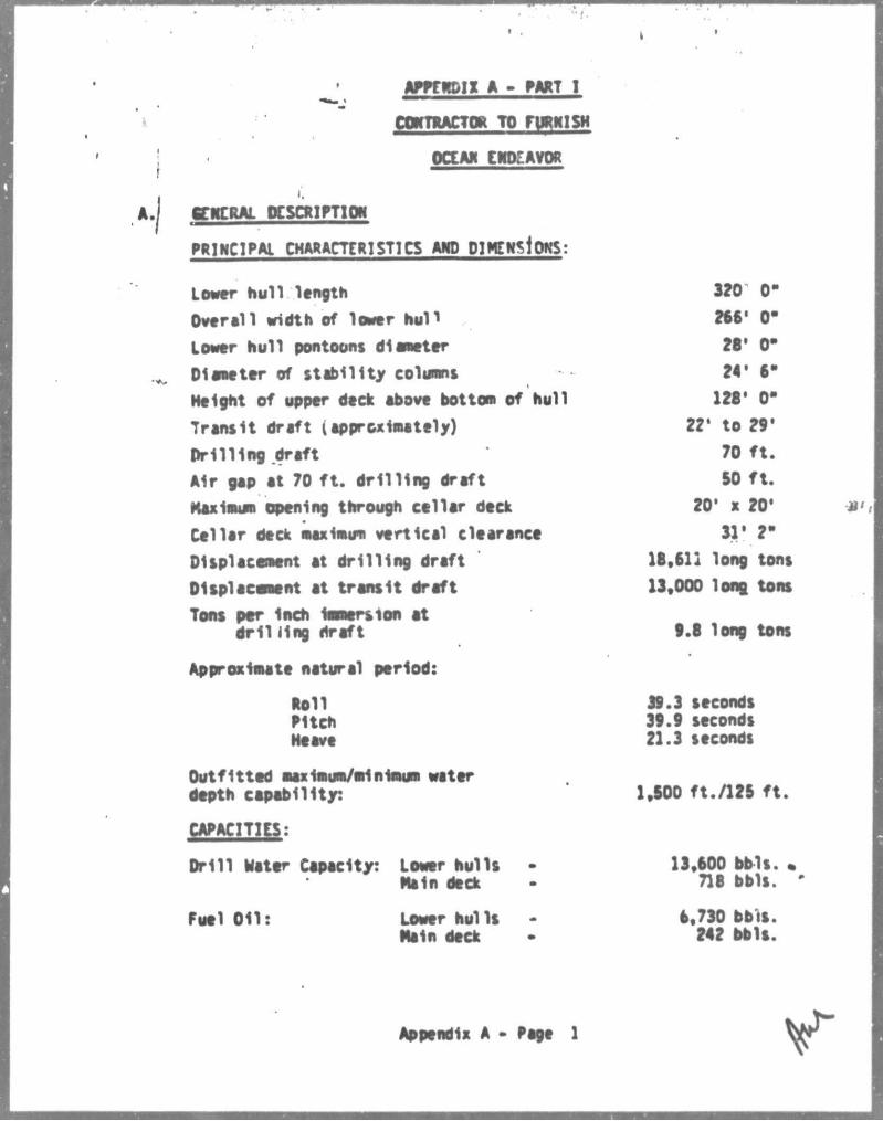
APffNDIX A - PART I
CtOTUCTOR TO FURNISH
OCEAN EMO.". A VOR
gWCRAL CCSCNlfTlON
PRINCIPAL CHAR ACTE Rl STl CS AND DIMENSIONS:
Lover hull length
Overall width ef lower nun
Lower hull pontoons diameter
Diameter of stabil ity columns
Height of upper deck above botton of hull
Transit draft (approximately)
Pr i l l ing draft
Air gap at 70 f t . dri l l ing draft
Maximum opening through cellar deck
Cellar deck maxinum vertical clearance
Displacement at dri l l ing draft
Displacement at transit draft
Tons per Inch immersion at dr l l I1ng draft
Approximate natural period:
Noll Pitch Heave
Outfitted maximum/minimum water depth capability:
CAPACITIES:
Dril l Mater Capacity: Lowar hulls Main deck
320 0-
266' 0"
28* 0*
24' 6-
128* 0-
221 to 29'
70 f t .
SO f t .
20' x 20*
11' 2"
18,611 long tons
13,000 long tons
9.8 long tons
39.3 seconds 39.9 seconds 21.3 seconds
1,500 ft./125 f t .
13,600 bbls. 718 bbls.
Fuel O i l : Lower hulls Main deck
6,730 bbis. 242 bbls.
Appendix A - Page 1
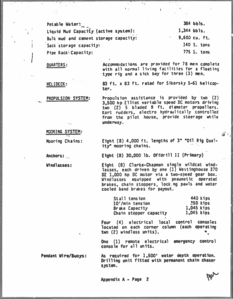
Potable Water!
Liquid Nud Capacity (active system):
Bulk mud and cement storage capacity:
Sack storage capacity:
384 bbls.
1,344 bbls. 9.600 cu. f t .
140 S. tons
77S S. tons Pipe Rack' Capacity:
QUARTERS:
HELIDECK:
PR0PULS1OK SYSTEH:
MOORINS SYSTEM:
Mooring Chains:
Anchors:
Windlasses:
Pendant Wire/Buoys:
Accommodations are provided for 78 men complete with al l normal living faci l i t ies for a floating type rig and a sick bay for three (3) men.
83 f t . x 83 f t . rated for Sikorsky S-61 helicopter.
Propulsion assistance 1s provided by two (2) 3,500 hp E l l io t variable speed DC motors driving two (2) 5 bladed 9 f t . diameter propellers. Kort rudders, electro hydraulically controlled from the pilot house, provide steerage while underway.
tf'i Eight (8) 4,000 f t . lengths of 3" -011 Rig Qual* Ity" mooring chains.
Eight (8) 30,000 lb. Offdrill I I (Primary)
Eight (8) Clarke-Chapman single wildcat windlasses, each driven by one (1) Wettlnghouse 370 DZ 1,000 hp DC motor via a two-speed gear box. Windlasses equipped with pneumatic operated brakes, chain stoppers, lock ng pawls and water cooled band brakes for payout.
Stal l tension 440 kips lO'/min tension 250 kips Drake Capacity 1,045 kips Chain stopper capacity 1,045 kips
Four (4) electrical local control consoles located on each comer column (each operating two (2) windlass units). %
One (1) remote electrical emergency control console for a l l units.
Aa required for 1,800' water depth operation. Drilling unit fitted with permanent chain chaser system.
Appendix A - Page 2
Towing equipment: , Two (? ) tow bridles 2-1/2" x 200'.
CUSS: AIS-A«S- Maltese Cross Al M Column stabilized, propi ion assftted semisubmersible drilling unit.
r
jomi got* WIPICITT
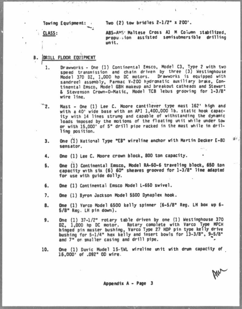
1. Drawworks • One (1) Continental Emsco, Model C3, Type 2 with two speed transmission and chain driven by three (3) Westinghouse Model 370 DZ, 1,000 hp DC motors. Drawworks is equipped with sendreel assembly, Parmac V-200 hydromatic auxiliary brake. Continental Emsco, Model GBH makeup and breakout catheads and Stewart i Stevenson Crown-O-Matic. Model TCB lebus grooving for 1-3/8" wire line.
**t. Mast - One (1) Lee C. Moore cantilever type mast 162* high and with a 40* wide bate with an API 1,400,000 lb. static hook capacity with 14 lines strung and capable of withstanding the dynamic loads Imposed by the motions of the floating unit while under ton or with 15,000' of 5" dr i l l pipe racked in the mast while in dr i l ling position.
3. One ft) National Type "EB" wireline anchor with Martin Decker E-80 sensator.
4, One (1) Lee C. Moore crown block, 800 ton capacity.
8. One (1) Continental Emsco, Model RA-60-6 traveling block, 880 ton capacity with six (6) 80" sheaves grooved for 1-3/8" line adapted for use with guide dolly.
6. One (1) Continental Emsco Model L-660 swivel.
7. One (1) Byron Jickson Model 6500 Dynaplex hook.
8. One (1) Varco Model 6500 kelly spinner (6-5/8" Reg. LN box up 6-6/8* Nog. LN pin down).
t . One (1) 37-1/2" rotary table driven by one (1) westinghouse 370 DZ, 1,000 hp DC motor. Notary complete with Varco Type MPCN hinged pin master bushing, Verco Type 27 HDP pin type kelly drive bushing for 5-1/4" hex kelly and Insert bowls for 13-3/8", 9 ; 5/8' end 7" or smaller casing end dr i l l pipe.
10. One (1) Duvic Model 15-SML wireline unit with drum capacity of 16,000' of .082" OD wire.
Appendix A - Page 3
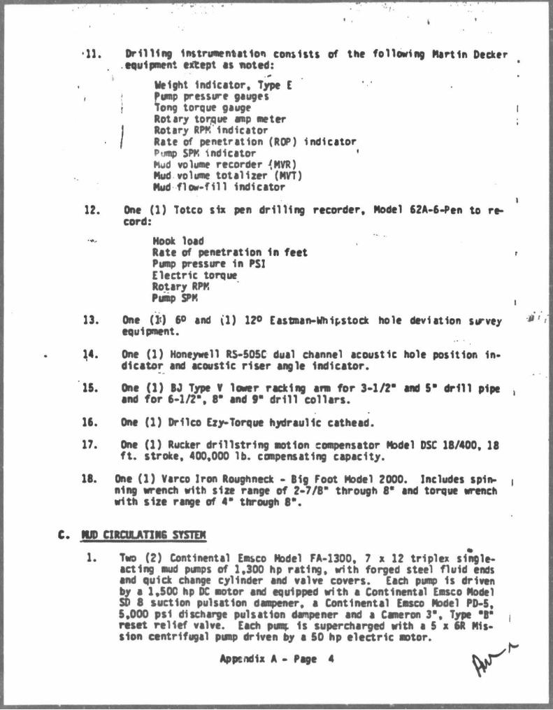
•11. Drilling Instrumentation consists of tne following Martin Decker equipment except as noted:
Height Indicator, Type I f imp pressure gauges
f Tong torque gauge Rotary torque amp meter
I Rotary RPM Indicator / Rate of penetration (ROP) indicator
Pump SPK indicator ' Mud volume recorder 4MOT) Mud volume totalizer (Mn) Mud flow-fill indicator
12. One (1) Totco six pen drill ing recorder. Model 62A-6-Pen to record:
Hook load Rate of penetration In feet Pump pressure in PSI Electric torque Rotary RPM Pump SPM
13. One (1<) 6° and i l ) 12° Eastman-Whipstocx hole deviation survey equipment.
14. One (1) Honeywell RS-505C dual channel acoustic hole position Indicator and acoustic r iser angle Indicator.
15. One (1) I J Type V lower racking ana for 3-1/2" end 5" dr i l l pipe end for 6-1/2", 8" and 9" dr i l l col lars.
16. One (1) Drilco Ely-Torque hydraulic cathead.
17. One (1) Rucker dril lstrlng motion compensator Model DSC 18/400, 18 f t . stroke, 400,000 lb. compensating capacity.
18. One (1) Varco Iron Roughneck - Rig Foot Model 2000. Includes spinning wrench with size range of 2-7/6" through 6" and torque wrench with size range of 4" through 6".
MJD CIRCULATIM6 SYSTEM
1. Two (2) Continental Emsco Model FA-1300, 7 x 12 triplex single-acting mud pumps of 1,300 hp rating, with forged steel fluid ends and quick change cylinder and valve covers. Each pump Is driven by a 1,500 hp DC motor and equipped with a Continental Emsco Model SD 8 suction pulsation dampener, a Continental Emsco Model PD-5, 5,000 psl discharge pulsation dampener and a Cameron 3", Type "8" reset relief valve. Each pumc Is supercharged with a 5 x 6R Mission centrifugal pump driven by a 50 hp electric motor.
Appendix A - Pege 4
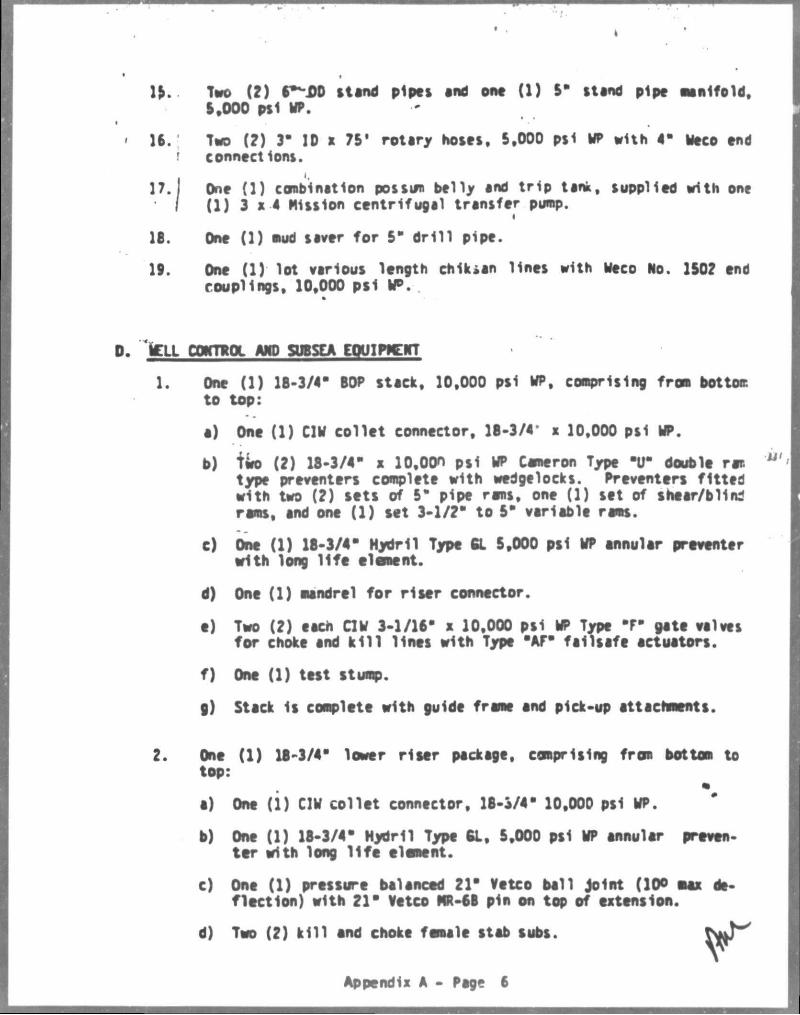
\ y Two (2) 6—X)D Uand pipes end one (1) 5" stand pipe manifold, S.OOO psl WP.
16. Two (2) 3" ID a 7S' rotary hoses. 5,000 psl WT with 4" Weco end ' connections.
18. One (1) mud saver for 5* dr i l l pipe.
19. One (1) lot various length ch1k»an lines with Weco No. 1502 end couplings, 10,000 psi I F .
'iClX CONTROL AND SUBSEA EOUIWCNT
1. One (1) 18-3/4- BOP stack, 10,000 psi WP, comprising from botton: to top:
a) One (1) CIW collet connector, 18-3/4' x 10,000 psi WP.
b) two (2) 18-3/4* a lO.OOn psi WP Cameron Type I T double ram type preventers complete with wedgelocks. Preventers fitted with two (?) sets of 5" pipe rams, one (1) set of shear/blind rems, and one (1) set 3-1/2" to 5" variable rams.
c) One (1) 18-3/4" Hydril Type 6L 5,000 psl WP annular preventer with long l i fe element.
d) One (1) mandrel for r iser connector.
e) Two (2) each CIW 3-1/16" x 10,000 psi WP Type "F" gate valves for choke and k i l l lines with Type "AP" failsafe actuators.
f) One (1) test stump.
g) Stack 1s complete with guide frame and pick-up attachments.
2. One (1) 18-3/4" lower riser package, comprising from bottom to
a) One ( i ) CIW collet connector, 18-3/4- 10,000 psi WP.
b) One (1) 18-3/4" Hydril Type 61, 5,000 psi WP annular preventer with long l i f e element.
c) One (1) pressure balanced 21" Vetco ball Joint (10° max da-flection) with 21" Vetco HR-6B pin on top of extension.
One (1) combination possum belly and trip tank, supplied with one (1) 3 x 4 Mission centrifugal transfer pump.
d) Two (2) k i l l end choke female stab subs.
Appendix A - Page 6
*
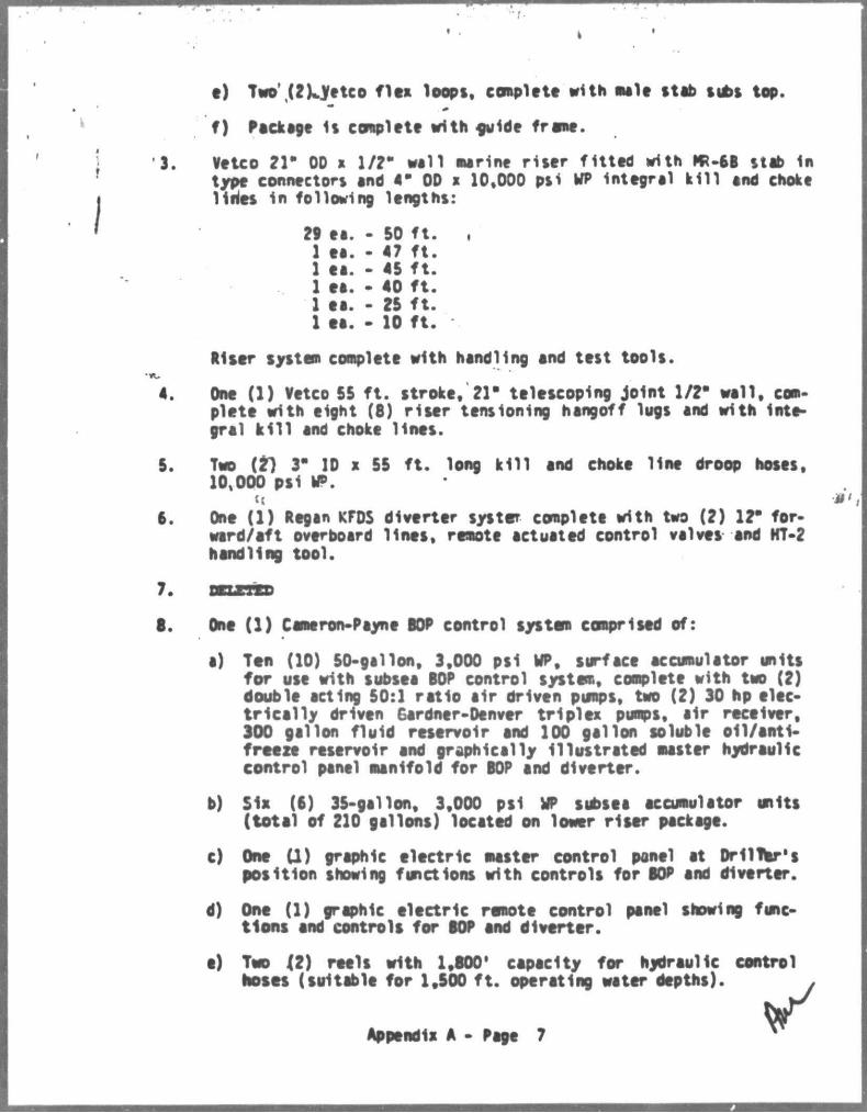
e) Two' (2)„yetco fits loops, complete with male stab subs top.
f) Package is complete with guide frame.
Vetco 21" OD a 1/?* wall marine riser fitted with KU5B stab in type connectors and a* OD a 10,000 psi wT integral ki l l and choke liries in following lengths:
29 ea. - SO ft . , 1 ea. • 47 ft . 1 ea. - 45 f t . 1 ea. - 40 f t . 1 ee. - 25 f t . 1 ea. - 10 f t .
Riser system complete with handling and test tools.
One (1) Vetco 55 ft . stroke, 21" telescoping joint 1/2" wall, com-plete with eight (8) riser tensioning hangoff lugs and with integral k i l l and choke lines.
Two (t) 3" ID a 55 ft. long ki l l and choke line droop hoses, 10,000 psi * ? .
ct One (1) Regan KFDS diverter systmr complete with two (2) 12" for-ward/aft overboard lines, remote actuated control valves and HT-2 handling tool.
One (1) Cameron-Payne BOP control system comprised of:
a) Ten (10) 50-gallon, 3,000 psi UP, surface accumulator units for use with subsea BOP control system, complete with two (2) double acting 50:1 ratio air driven pumps, two (2) 30 hp electrically driven Gardner-Denver triplex pumps, air receiver, 300 gallon fluid reservoir and 100 gallon soluble oil/antifreeze reservoir end graphically Illustrated master hydraulic control panel manifold for BOP and diverter.
b) Six (6) 35-gallon, 3,000 psi UP subsea accumulator units (total of 210 gallons) located on lower riser package.
c) One (1) graphic electric master control panel at Dri lifer's position showing functions with controls for BOP and diverter.
d) One (1) graphic electric remote control panel showing functions and controls for BOP and diverter.
e) Tuo IZ) reels with 1,800' capacity for hydraulic control hoses (suitable for 1,500 ft . operating water depths).
Appendix A - Page 7
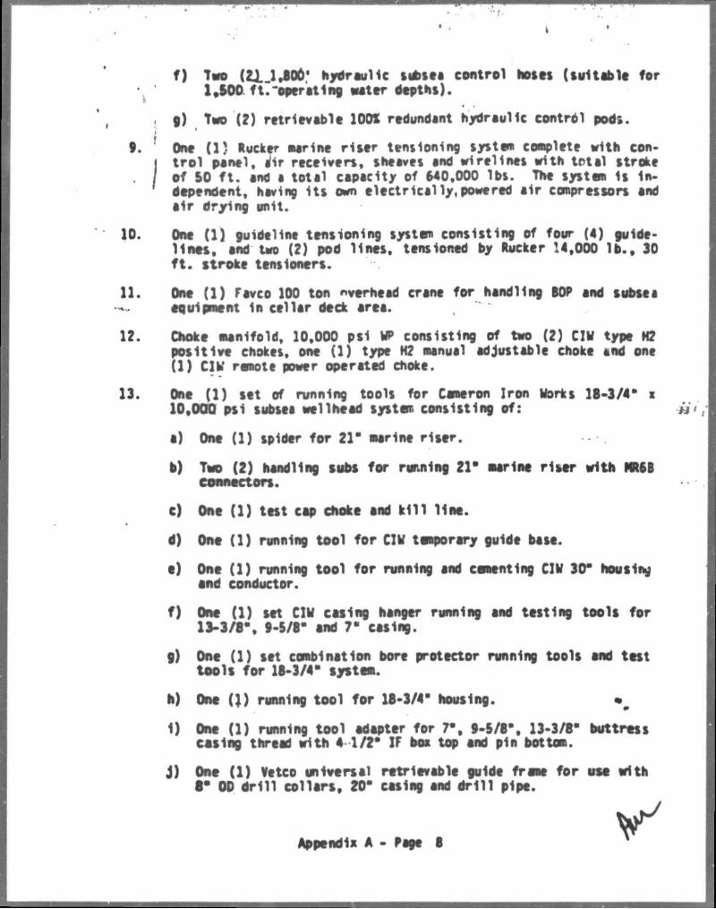
f ) Tvo (21 1.806' hydraulic subset control hosts (suitable for •. 1.500 ft.-operating water depths).
5 g) Two (2) retrievable 1001 redundant hydraulic control pods. i 1
9. One (1) Rucker aarine riser tensioning system conplete with con-I trol panel, air receivers, sheaves and wirelines with total stroke
. / ef 50 f t . and a total capacity of 640,000 lbs. The systen is in-dependent, having i ts own electrical ly, powered air compressors and air drying unit.
10. One (1) guideline tensioning system consisting of four (4) guidel ines , and two (2) pod l ines, tensioned by Rucker 14,000 l b . , 30 f t . stroke tensioners.
11. One (1) Fevco 100 ton overhead crane for handling BOP and subsea equipment in cellar deck area.
12. Choke manifold, 10,000 psi UP consisting of two (2) C1U type N2 positive chokes, one (1) type H2 nanual adjustable choke and one (1) CIU remote power operated choke.
13. One (1) set of running tools for Cameron Iron Works 18-3/4* s 10,000 psi subsea wellhead system consisting of: « ' ,
a) One (1) spider for 21* marine rlaer.
b) Two (2) handling tubs for running 21" aarine riser with NR6B connectors.
c) One (1) test cap choke and k i l l Une.
d) One (1) running tool for CIU temporary guide base.
e) One (1) running tool for running and cementing CIU 30" hooting end conductor.
f) One (1) tet CIU eating hanger running and testing tools for 13-3/8", 9-5/8" and 7" casing.
g) One (1) tet combination bore protector running tools end test tools for 16-3/4" system.
h) One ( ) ) running tool for 18-3/4" hooting. m#
1) One (1) running tool adapter for 7", 9-5/8", 13-3/8" buttress eating thread with 4 1/2* IF box top and pin bottom.
j ) One (1) Vetco universal retrievable guide frame for use with 8" 00 dr i l l col lars, 20" eating and dr i l l pipe.
Appendix A - Page 6
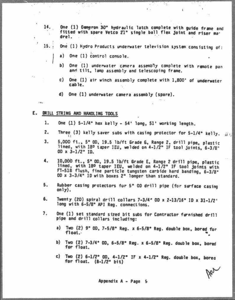
14. One (1) C-emeron 90" hydraulic latch complete with guide frame and f i t ted with spare Vetco 71" single ball flea joint and riser madre 1.
15. j One (1) Hydro Products underwater television system consisting of :
| a) One (1) control console.
b) One (1) underwater camera assembly complete with remote pan ami t i l t , lamp assembly and telescoping frame.
c) One (1) air winch assembly complete with 1,800' of underwater coble.
d) One (1) underwater camera assembly (spare).
DRILL STKIH6 AHD HAMDllWC TOOLS
1. One ( I ) 5-1/4' hex kelly - 54' long, S l ' working length.
2. Three (3) kelly saver subs with casing protector for 5-1/4" kelly.
3. 59000 f t . , 5" 00, 19.5 lb/ft Grade 6, Range 2, dr i l l pipe, plastic lined, with 18* taper IEU, welded on 4-1/2" IF tool jointt, 6-3/8* OD x 3-1/2" ID.
4. 10,000 f t . , 5" 00, 19.5 lb/ f t trade E, Range 2 d r i l l pipe, plastic lined, with 16* taper IEU, welded on 4-1/2" IF tool joints with rT-518 flush, fine particle tungsten carbide hard banding, 6-3/8" OD x 3-3/4" ID with boxes 2" longer than standard.
5. Rubber casing protectors for 5" OD d r i l l pipe (for surface casino only).
6. Twenty (20) spiral d r i l l col lars 7-3/4" OD a 2-13/16" ID x 31-1/2' long with 6-5/8" API Reg. connections.
7. One (1) tet standard tired bit subs for Contractor furnished dr i l l pipe end dr i l l collars Including:
•) Two (2) 9" OD, 7-5/8" Reg. x 6-5/8" Reg. double box, bored for float.- \
b) Two (2) 7-3/4" OD, 6-5/8" Reg. x 6-5/6" Reg. double box, bored for float.
c) Two (2) 6-1/2" OD, 4-1/2" IF x 4-1/2" Reg. double box, boreo for float. (6-1/2" bit)
Appendix A - Page 5
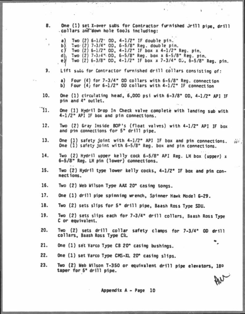
6. One (1) tet X-over tubt for Controctor furnished JM11 pipe, a n i l col lars arib~~down hole tools Including:
a) Two (?) 8-1/?* 00, 4-1/?- IF double pin.'' b) Two (?) 7.3/4* OD, 6-5/8- Reg. double pin. cjf Two (?) 8-1/?- 00, 4 -1 /?- IF box x 4 -1 /?- Reg. pin. dj. Two (?) 7-3/4". OD, 6-5/8 a Reg. box x 6-5/8" Reg. pin. e)/ Two (?) 6-3/8" OD, 4-1 /?- IF box x 7-3/4" OJ, 6-5/8* Reg. pin.
a) Four (4) for 7-3/4- OD collars with 6-5/8" Reg. connection b) Four (4} for 6-1/2" 00 collars with 4-1/?" IF connection
10. One (1) circulating head, 6,000 psi with 6-3/8" 00, 4-1/?- AP] IF pin and 4" outlet.
11. One (1) Hydril Drop In Check valve conplete with landing tub with 4-1/2" API IF box and pin connections.
12. Two (2) 6ray Inside BOP's (float valves) with 4-1/2" API IF box and pin connections for 5" dr i l l pipe.
13. One (1) safety joint with 4-1/2" API IF box and pin connections, u i , One (1) safety joint with 6-5/8" Reg. box and pin connect ions.
14. Two (2) Hydril upper kelly cock 6-5/8" API Reg. LH box (upper) x 6-5/8" Reg. LH pin (lower) connections.
15. Two (2) Hydril type lower kelly cocks, 4-1/2" IF box and pin connections.
16. Two (2) Web Hilton Type AAX 20" eating tongs.
17. One (1) dri l l pipe spinning wrench. Spinner Hawk Model 6-28.
18. Two (2) sets slips for 5" dr i l l pipe, Baath Rest Type SOU.
19. Two (2) tett slips eech for 7-3/4" d r i l l collars, Baath Ross Type C or equivalent.
20. Two (2) tett dr i l l col lar tafety clamps for 7-3/4" 00 dr i l l col lars , Baath Ross Type CR.
21. One (1) set Varco Type CB 20" eating bushings.
22. One (1) tet Varco Type CMS-XL 20" eating s l ips .
23. Two (2) Web Wilton T-350 or equivalent dr i l l pipe elevators, 180 taper for 5" dril l pipe.
3. L i f t sufe» for Contractor furnished dr i l l collars consisting of:
Appendix A - Page 10
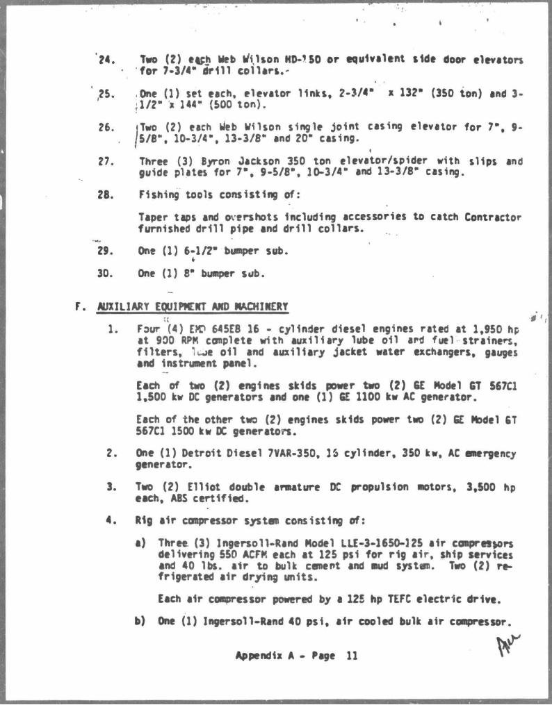
24. Tvo (2) each Web Wilson HD-1 SO or equivalent tide door elevators for 7-3/4" dr i l l co l lars . -
' ?5. One (1) set each, elevator l inks, 2-3/4- x 13?" (3S0 ton) and 3-r l / ? " a 144- (SOO ton).
?6. |Two (?) each web Wilson single joint casing elevator for 7", 9-. / 5 / 8 \ 10-3/4-, 13-3/8- and ?0- casing.
?7. Three (3) Byron Jackson 350 ton elevator/spider with slips and guide plates for 7", 9-5/8", 10-3/4- and 13-3/8" casing.
?8. Fishing tools consisting of:
Taper taps and overshots including accessories to catch Contractor furnished dr i l l pipe and dr i l l col lars.
29. One (1) 6-1/2" bumper sub.
30. One (1) 8" bumper sub.
AUXILIARY EQUIPMENT AHD MACHINERY
1. Four (4) EM? 645E8 16 - cylinder diesel engines rated at 1,950 hp at 990 RPK complete with auxiliary lube oil ard fuel strainers, f i l t e rs , " JC oil and auxiliary jacket water exchangers, gauges and Instrument panel.
Each of two (2) engines skids power two (2) GE Model GT 567C1 1,500 kw DC generators and one (1) 6E 1100 kw AC generator.
Each of the other two (2) engines skids power two (2) CE Model 6T 567C1 1500 kw DC generators.
2. One (1) Detroit Diesel 7VAR-350, 16 cylinder, 350 kw, AC emergency generator.
3. Two (2) Ell lot double armature DC propulsion motors, 3,500 hp each, ABS certif ied.
4. Rig air compressor system consisting of:
a) Three (3) Ingersoll-Rand Model LLE-3-1650-125 air compressors delivering 550 ACFK each at 125 psi for rig a i r , ship services and 40 lbs. air to bulk cement and mud system. Two (2) refrigerated air drying units.
Each air compressor powered by a 125 hp TEFC electric drive.
b) One (1) Ingersoll-Rand 40 p s i , air cooled bulk air compressor.
Appendix A - Page 11

c) One JJ) e lectr ical ly driven and one (1) diesel driven cold Start air compressor.
-5. Two (?) Fevco Model 1000 pedestal mounted diesel hydraulic revol
ving cranes vith )?0 f t . booms and 10 f t . personnel j i b . Cranes • fitted vith hook load indicator.
1 Capacity: ?3 tons at 90 f t . radius. ' 40 tons at 30 f t . r.adius.
6. Baskets and nets for personnel and cargo handling.
7. One l l ) Nirex, JWP-36-C Series Alfe-Laval, 10,000 GPD vater maker.
8. One (1) forklift truck for handling palletized and other materia ls .
9. One (1) set hoses complete vith proper end connections for on and off loading of vater, fuel , dry mud and cement, e tc . , and sufficiently long to reach the supply vessel. Replacement hoses provided by Operator.
10. Seven (7) 25-man inflatable l i fe rafts.
11. Four (4) 50-man enclosed lifeboats.
12. Safety equipment to include:
a) Tvo (2) f i re sui ts . b) Tvo (2) oxygen breathing apparatus. c) Five (5) thirty minute back packs.
13. One (1) 'Normald" automatic CO? protection system installed in motor and propulsion rooms.
14. One (1) *Satec" smoke detector system vith monitor in baro; control roor monitoring port and sta^boara propulsion roors, machinery and engine room and laundry.
15. Three (3) welding machines, 300/400 AMP, diesel and rectifier type.
16. Navigation and Commjrhcation Equipment to meet ABS and SOLAS requirements.
0
17. Fire Fighting and Safety Equipment to meet ABS and SOLAS requirements.
18. One (1) oil vater separator unit.
19. One (1) sever age treatment system.
Appendix A - Page 11 (a)
S. THIRD PARTY EQUIP*.*!
1. One (1) Halliburton HT-400 twin skid mounted diesel powered cement ing unit with recirculat ing mixer and low pressure mixer. (Operator to provide for Maintenance and operation of unit and to pay a l l additional costs i f other than Hal l ibur ton services are u t i l ized for operation of un i t . )
H. OTHER SERVICES PROVIDED tY OPERATOR:
1. One (1) electric logging unit.
Appendix A - Page 11 (b)
M :bil Exploration A.Producing U.S. Inc.
December 22, 1987 Nf * OWtEANS DIVISION
no STOMAS BUILOINC
N€*0*l.£A*S LCU'SIANA '0«3 <ati
State Times LegaJ Ad Department P.O. Box 588 Baton Rouge, LA 70821
Attn: Mi. Heather Allen
7.40.00.00 PLAN OF EXPLORATION EWING BANK BLOCK 871 OCS-G-5807 REQUEST FOR PUBLICATION LEGAL CLASSIFIED AD
Dear Ms. Allen:
Please publish the attached notice on January 5, 1988, one day only.
The Invoice for the ad should be mailed to the belov address to the attention of Payables. The proof of publication should also be mailed to the same address but to the attention of E . F . Glass .
Mobil Exploration & Producing U.S . Inc . 1250 Poydras Building New Orleans, LA 70113
I f you have any questions, please c a l l me at (504) 566-5773.
kYours. .vary t ru ly ,
L . Horne S r . Environmental & Regulatory Engineer
JLH/cal ERA30445
cc : Department of the Interior Minerals Management Service 1201 Elmwood Park Boulevard New Orleans. LA 70123-2394 Attn: Regional Supervisor FO-2-1 Attn: Mr. Joel Lindsey
LA. Department of Natural Resources Coastal Management Section P.O. Box 44124 Baton Rouge, LA 70804
Payables
APPLICANT:
LOCATION:
P u b l i c N o t i c e pf F e d e r a l C o n s i s t e n c y review of a Proposed Explorat ion Plan by the Coas ta l Management •Section/Louisiana Department of Natural Resources for the p l a n ' s consis tency with the Louis iana Coas ta l Resources Program.
Mobil Exploration & Producing U.S. Inc. Attn: Jerry L . Home Senior Environmental Ji Regulatory Engineer 1250 Poydras Street New Orleans, Louisiana 70113
Ewing Bank Lease OCS-G-5801 Block 871 Lease Sale OCS Sale 72 (May 1983)
DESCRIPTION: Proposed exp lorat ion plan for the above block p r o v i d e s for the explorat ion of o i l and gas. Explorat ion a c t i v i t i e s w i l l include d r i l l i n g from a d r i l l r i g and transport of d r i l l i n g crews and equipment by hel icopter and/or cargo vessels from an onshore base a t V e n i c e , L o u i s i a n a . No e c o l o g i c a l l y s e n s i t i v e h a b i t a t s or species are known to be located near or are expected to be a f f e c t e d by these a c t i v i t i e s .
A copy of the plan described above i s avai lable for inspection at the Coastal Management Section Of f i ce located on the 10th Floor of the State Lands and Natural Resources Building, 625 North 4th S t r e e t , Baton Rouge, Louisiana. Of f i ce hours: 8 AM to 4:30 PM, Monday through F r i d a y . The p u b l i c i s requested to submit comments to the Coasta l Management Section, Attention OCS plans. P .O. Box 44396, Baton Rouge, La 70804. Comments must be received w i t h i n 15 days of the date of t h i s notice or 15 days af ter the Coasta l Management Section obtains a copy of the plan and i t i s ava i lab le for publ ic inspection, 'rhis poblic notice i s provided to meet the requirements of. the NOAA Regulat ions on Federa l Consistency v i th approved Coastal Management Programs.
$ -T X 3 I M
I,
ENVIRONMENTAL REPORT (EXPLORATION) EWING BANK BLOCK 871 (OCS-G-5801)
LESSEE/OPERATOR: MOBIL EXPLORATION AND PRODUCING U.S. INC.
CONTACT PERSON:
Mr. Jer r y L. Home Senior Environmental & Regulatory Engineer Mobil Exploration 6 Producing U.S. Inc. 1250 Poydras Street New Orleans, Louisiana 70113
Telephone: (504) 566-5773
18 December 1987
I j DESCRIPTION OF THE PROPOSED ACTION
This! Environmental Report addresses the proposed d r i l l i n g
act iv i t ies re la ted to three exploration wells dn Ewing Bank bloc):
871 by Mobil Explorat ion and Producing U.S . I n c . , lessee dnd
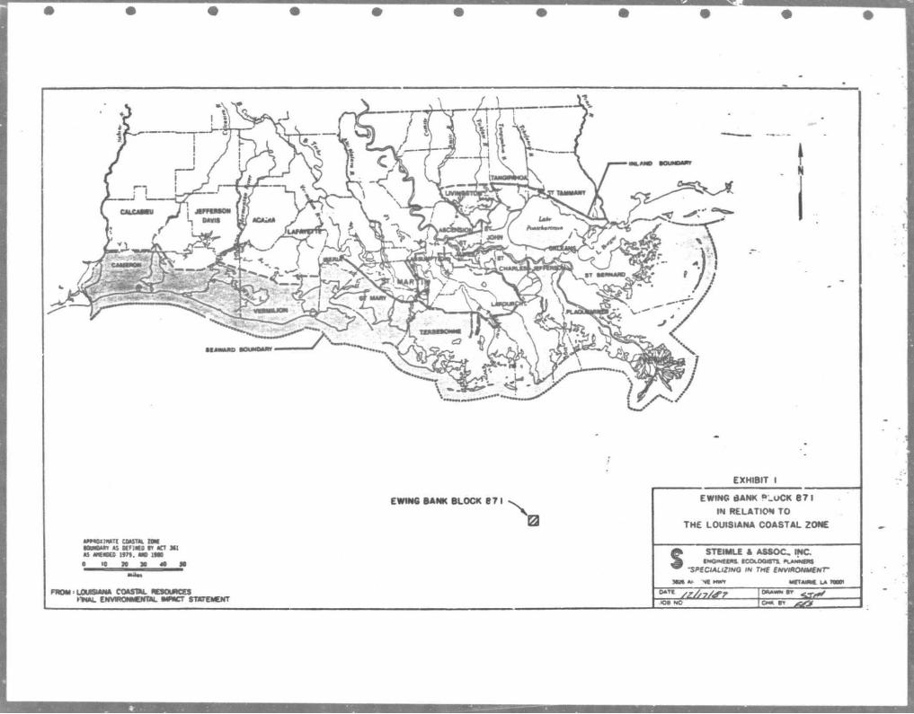
operator. The center of the block i s located approximately 98
miles southwest of Venice, Louisiana, at which i s located tbe
onshore support base for the a c t i v i t y . The nearest mainland
shore is located approximately 67 miles north near l imbal ier Bay.
The location of Ewing Bank block 871 in relation to the Louisiana
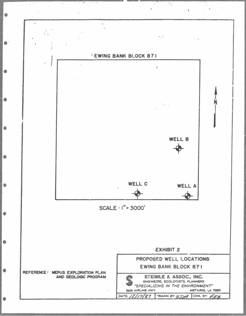
Coastal Zone i s shown in E x h i b i t 1. The locat ions of the
proposed exploratory wells within the block are shown in Exhibit
2.
As stated in the axploration plan and geologic program for
Ewing Bank block 871, thiee exploration wells, (J h k C) , w i l l
be dri l led in the block. The wells w i l l be d r i l l e d to to ta l
v e r t i c a l depths of 16,000 f t . , 11,000 f t . anJ 8,000 f t . ,
respectively.
Ewing Bank block 371, Well A, w i l l be the i n i t i a l we l l
dr i l led with an anticipated spud date of March 1, 1988. I t i s
projected to take an estimated 60 days of d r i l l i n g to complete
the well. The order of d r i l l i n g and estimated spud dates for the
remaining two w e l l s have not yet been decided. The d r i l l i n g
period est imate of 60 days w i l l a l so apply to each of the
remaining we l l s . The combined v e r t i c a l depth of the three wells
S m
i s i5,000 f t . Based on the 60 day drilling period per well,
drilling should be completed by the end of August, 1988. The
wells will be d r i l l e d from the semisubmersible rig, Ocean
Endeavor, in approximately 810 ft. of water.
The onshore support base for the exploration of Ewing Bank
block 871 w i l l be Venice, Louisiana. No new f a c i l i t i e s are
envisioned in relation to this activity. Existing f a c i l i t i e s are
anticipated to be sufficient for a l l supoort activities. No new
workers are expected to be employed for this a c t i v i t y as an
existing d r i l l rig and crew will be utilized. The f i r s t socio
economic data base report will be submitted when the MMS and the
states of Alabama, Louisiana, and Mississippi identify the
specific parameters to be addressed in these semi-annual reports.
The surface travel route betwaen the proposed well sites and
the support base w i l l be by the Mississippi Fiver through
Southwest Pass and into the Gulf of Mexico. The air route wil l
be a straight line to Ewing Bank block 871 from Venice. Three
surface vessels and one helicopter will normally be employed in
support of this activity. A crew boat is expected to make 2
round trips per 7 days and a supply boat is expected to make 1
round trip per 3 days. A standby boat operating 23 hours per day
wi l l attend the rig throughout operations. One helicopter wi l l
make one round trip pe*- day.
2
t
' No new or unusual techniques or technology that may affect
coastal waters w i l l be used in this exploratory d r i l l i n g program.
Due to the wildcat nature of the d r i l l i n g program, no development
or production plan has been formulated at th is time. At the
a p p r o p r i a t e time ( a f t e r the e x p l o r a t o r y program) , a
development/production plan giv ing the proposed means and
location of gas and/or o i l t ranspor ta t ion f a c i l i t i e s w i l l be
presented.
DESCRIPTION OF THE AFFECTED ENVIRONMENT AND IMPACTS
a. Physical and Environmental
(1) Commercial Fishing
Data p r e s e n t e d i n the R e g i o n a l E n v i r o n m e n t a l Impact
Statement for the Gulf of Mexico region shows Ewing Bank block
871 to be located near a productive f i s h i n g area . The mean
yearly catch for the area north of the block was 46.8 mil l ion
pounds (combined f in and s h e l l f i s h ) for the years 1977 through
1981. The major f i shery in the area i s menhaden (Brevoort ia
patronus) . The most common sportf i sh caught in the area Include
kir.g mackerel (Scomberomorus c a v a l l a ) . c r e v a l l e j a c k (CarflnX
hippos) , wahoo (Acanthocvbium solanderi) , and dolphin (Coryphaena
hlPPurys).
Commercially important species of shrimp, the moat common
being brown shrimp (Penaeus a z t e c u s ) and white shr imp (P.
setiferus) . are taken ir. the v i c i n i t y of Ewing Bank block 871.
s -N e a r l y 91,350 tons of shrimp were c o l l e c t e d by commercia l
fishermen in 1986 along the coast of the northern Gulf of Mexico,
thus providing fishermen with ar, abundant economic resource.
Major o y s t e r grounds are located northwest of Ewing Bank
b lock 871 in the inshore waters of Terrebonne P a r i s h . The
nearest reported grounds are approximately 68 miles north of the
blocks in Terrebonne Parish.
Impacts to the offshore f i sher i e s w i l l resu l t from loss of
trawling area for f ishing vessels due to the physical presence c f
the equipment and a decrease in water quality in the immediate
a r e a of the r i g from the discharge of d r i l l i n g f l u i d s and
cutt ings .
The d r i l l i n g r i g v i l l prevent commercial f ishermen from
using one to two hectares of bottom during the d r i l l i n g period.
Discharge of usad d r i l l i n g f l u i d - and c u t t i n g w i l l decrease
water quality causing commercially important species to avoid the
immediate a r e a . As the c u t t i n g s and mud p a r t i c l e s s e t t l e ,
t u r b i d i t y w i l l drop and t h i s s h o r t term impact * i l l be
a l l ev ia ted .
Treated sanitary waste, produced waters, r i g wash, runoff ,
and desal inization waste are to be discharged from the r i g . These
discharges should not s ign i f i cant ly a f fec t commercial f i sh ing as
t h e volume of water i s so great r e l a t i v e to t\m volume of
s *
i J eff luent that dispersal w i l l be rapid.
i.
(2) SroaJjl C r a f t Pleasure goating, Sportfishing and Recreation
Ewing Bank block 871 i s located 67 miles from the nearest
mainland shore . Explorat ion in t h i s block w i l l probably not
a f f ec t recreat ional boating oi sportfishing due to i t s distance
offshore. Temporary loss of one to two hectares for f i sh ing w i l l
be incurred during the d r i l l i n g per iod . T h i s impact w i l l
terminate when the d r i l l i n g operation i s complece.
The d r i l l i n g r i g w i l l present a s l i g h t h i n d r a n c e to
navigation for f i shing vessels . However, the r i g ' s presence in
the area w i l l serve as a safe ty fac tor f o r v e s s e l s needing
emergency help and as a reference point.
R e c r e a t i o n a l beaches found along the coast of J e f f e r s o n
Parish in Louisiana are located approximately 78 miles to the
northeast of Ewing Bank block 871. An o i l s p i l l could possibly
r* icn these shores, though the predominant westwardly current and
/est tc* southeast winds would lessen the Jikelanood that a s p i l l
* jilt : „ach these shores.
Disturbance to hunting and f ishing in the coastal zon. oy
boats v - i hel icopters servicing e operation should be minimal
in a*: already much traveled area.
• • • • .
(3) ?hippirtq
Ewing f̂eank block 871 i s located approximately 4.5 miles
north of the nearest safety fairway. The wells•located in Ewing
Bank block 8 71 w i l l be marked with l i g h t s to warn commercial
t r a f f i c of i t s presence, and are therefore, expected to have no
s ignif icant impact on commercial t r a f f i c in the Gulf of Mexico.
(4) Cultyrftl pesoyrces
Ewing Bank block 871 l i e s outside the area designated as
l ikely to y i e l d valuable cu l tura l resources. A shallow hazards
review has been completed by MEPUS. There a r e no known
shipwrecks w i t h i n the b lock. The c l o s e s t known shipwreck i s
located approximately 41 miles northwest of the center of the
block. No s i g n i f i c a n t impact i s expected on any c u l t u r a l
resources froro the d r i l l i n g ac t iv i ty in the block.
Available information shows that block 871 occurs in an area
with a c lay bottom. There are no known seafloor or subsurface
geologic and man-made features cr conditions that may adversely
affect the proposed operations.
(5) Ecological ly Sensit ive Features
The marsh-estuarine ecosystem inshore from Ewing Bank block
871 i s very productive. The extensive marsh-estuarine systems
along coastal Louisiana are u t i l i zed in the l i f e cycle of the
important commercial f i s h e s and s h e l l f i s h e s of the reg ion .
s J B X :
Typical' estuarine dependent, commercially important species such
as shrjmp and menhaden spawn offshore and migrate to the salt-
marshes as post larvae where they spend the juvenile stages of
their life history.
Although there are several wildlife refuges and management
areas found along the Louisiana coast, none are located in the
the immediate area of Ewing Bank block 871. The closest refuge
i s the Wisner National Wildlife Area located approximately 68
miles north of the block.
Two areas of biological significance l i e within 50 mi~.es of
Ewing Bank block 871. These areas are the Oiaphus Bank located
approximate.! y 24 miles to the west southwest and Ewing Bank
located approximately 40 miles west of the block. Both of these
features are raised areas of the Gulf bottom which may attract a
variety of plants and/or animals. Oue to the distance between
the blocks and the biologically sensitive areas, i t i s unlikely
that the d r i l l i n g activities will have any significant impact on
these areas.
Most of the major oyster areas in Louisiana are located in
southern Terrebonne Parish and eastward. The closest reported
oyster beds are located in Terrebonne Parish approximately 68
miles north of Ewing Bank block 871.
s E I :
Wateif q u a l i t y i s a f f e c t e d by s p i l l e d o i l . I f an o i l s p i l l
occurs, t ^ i* re would be a p o t e n t i a l adverse e f f e c t on marine
mammals and b i r d s . Birds have been se r ious ly a f f e c t e d by o i l
s p i l l s i n o t h e r p a r t s o f t h e w o r l d , bu t the re has been no
reported av ian m o r t a l i t y f rom o i l s p i l l s i n the Gulf o f Mexico.
The same i s t r u e o f mar ine mammals, a l though most species
recorded f o r the Gulf o f Mexico are a c t u a l l y very r a r e . O i l
s p i l l s i n t h e open G u l f do n o t v i s i b l y a f f e c t t h e m a r i n e
inver tebrate fauna. A smal l organism such as a copepod, would
surely be k i l l e d i f i t encountered s p i l l e d o i l , but the amount o f
water invo lved i s so great t h a t no known quan t i t a t i ve sampling
program could detect a p o p u l a t i o n change.
I f s p i l l e d o i l were t o reach shore, some impact would occur
on the shal low water b i o t a . There i s a small p o s s i b i l i t y t h a t
any l i q u i d pe t ro l eum hydrocarbons would reach shore * two
reasons. F i r s t , Ewing Bank b lock 871 i s a s i g n i f i c a n t dis tance
of fshore . Secondly, the predominant currents i n the area move
westwardly and the winds are predominately out of the east to
southeast. The impacts o f d r i l l i n g , t h e r e f o r e , on e c o l o g i c a l l y
s e n s i t i v e a r e a s i n t h e c o a s t a l zone a re e x p e c t e d t o be
i n s i g n i f i c a n t .
(6) Ex i s t i ng Pipel ines and Submarine Cables
There are no known o i l p i p e l i n e s or submarine cables located
i n t h i s b lock .
8
-1 1
I
(7) fO the r Mineral Uses
| Su lphur and s a l t , two i m p o r t a n t mir .erals e x t r a c t e d f rom
c o a s t a l L o u i s i a n a , a r e n o t known t o occur i n c o m m e r c i a l l y
feas ib le loca t ions and/or amounts w ".thin t h i s block.
(8) Ocean Dumping enc>_ F•.. l a t e d A c t i v i t i e s
No ocean dumpin' jntemplated i n t h i s b lock. A Nat iona l
Pol lu tant Discharge E l i m i n a t i o n System (NPDES) pe -»t f o r the
disch-»r«-j<? o f d r i l l i n g f l u i d s and c u t t i n g s , d e s a l i n i z a t i o n p l a n t
waste (conce:. ".rated sea r s l t s ) , t r ea ted sani tary waste, r a i n f a l l
runoff and d r i l l r i g washdown water has been received by MEPUS
from EPA Region V I , cover ing such discharges i n the Federal OCS
west o f l o n g i t u d e ^ 7 ° 4 1 " w i t h t h e e x c e p t i o n o f c e r t a i n
environmentally sens i t ive areas.
The m a j o r a n t i c i p a t e d d i s c h a r g e s f r o m t h e p r o p o s e d
exploratory wel l s w i l l be used d r i l l i n g f l u i d s , c u t t i n g s , and
formation waters. Using the estimates presented i n the D r a f t
Environmental Impact Statement f o i che 1980 O i l and Gas Lease
Sales A62 and 62, Vo'uroe 1, page 69, f o r a 13,000' w e l l , the
estimated 35,000' measured depth of the hole f o r the three w e l l s
w i l l produce approximately 257 tons of commercial mud components
and 2,217 tons of d r i l l c u t t i n g s . Mo r e l i a b l e estimates of the
amount of format ion waters produced from an explora tory w e l l can
be made a t t h i s t ime. As s t a t e i i n the previously c i t e d DEIS,
some components of d r i l l i n g f l u i d s are known t o be t o x i c t o
s -T B I :
certain organisms. The use \eshwater based d r i l l i n g f l u i d s
w i l l introduce i n t o the mar wironment r e l a t i v e l y non-toxic
d r i l l c u t t i n g s and format!-;, waters. The disposal of these
m a t e r i a l s a t the w e l l l o c a t i o n s can be expected t o cause l o v
level l o c a l i z e d adverse impacts on both bottom communities and
water q u a l i t y immediately adjacent t o the wells. A more complete
discussion of the impacts of d r i l l i n g f l u i d s , c u t t i n g s , and
formation waters i s presented i n the DEIS f o r lease sale A62 and
62, Volume 1, on pages 69 , 86, 87, 141, and 142. These
discussions cover impacts on the OCS areas p r i m a r i l y . The
primary impacts of the disposal of d r i l l i n g f l u i d s , c u t t i n g s , and
formation waters w i l l a l l occur and be l i m i t e d t o the offshore
area and not i n f r i n g e on the Louisiana Coastal Zone.
The other constituents of the proposed discharge from the
e x p l o r a t o r y w e l l s i n c l u d e d e s a l i n i z a t i o n p l a n t wastes (sea
s a l t s ) , t r e a t e d s a n i t a r y waste ( t o secondary t r e a t m e n t
s t a n d a r d s ) , r u n o f f ( r a i n w a t e r ) and r i g wash w a t e r ( o i l
separated) ind are t o be monitored i n accordance w i t h the
conditions of the EPA NPDES permit. No s i g n i f i c a n t wat«r q u a l i t y
impacts are expected from the disposal of these materials on the
OCS or coastal zone.
(9) Air Quality
Air emissions w i l l resul t from support vehicles (boats and
he l i copters ) as we l l as from the d r i l l i n g r i g . Ant ic ipated
10
s -emissions are a l l expected to be below MMS guideline limits and
are given jLn the Appendix. Aiiy waste material s u i t a b l e for
consumption by fi s h or other marine li-"e may be discarded into
the water. Any combustible waste products may be incinerated,
taking great care not to endanger the r i g . A l l non-edible, non-
combustible material i s to be collected and transported to shore
for proper disposal.
The most serious ambient a i r quality problems in the region
are around urban areas, p a r t i c u l a r l y those which are highly
i n d u s t r i a l i z e d . Although emissions data are important,
particularly when considering control alternatives, i t must be
remembered that ambient a i r quality offshore i s excellent, and
the discharge of gaseous emissions does not have the cumulative
impact that a similar volume of emission, would have in an area
with poor ambient a i r quality. These a i r emissions are expected
to have negligible impact on the coastal zone of Louisiana by
virtue of t h e i r small amount and distance offshore.
(10) Enflflnqerffl or Threatened Speci.es
All of the sea turtles which occur in the Gulf of Mexico are
endangered or threatened. None of them nest in Louisiana west of
the Mis i s s i p p i delta. The rarest of these turtles, the Atlantic
Ridley (Lepidochelys kempi) apparently uses the northern Gulf as
a feeding ground. The key to the s u r v i v a l of t h i s species,
however, i s in the protection of i t s nesting beach in Tamaulipas,
11
f Mexico. Other turt les fpund in the nor. iern Gulf of Mexico are
the green t u r t l e (Chelonia mvdas), loggerhead (Caretta care t ta ) ,
end the leatherback (Dermochelys coriacea) .
C e r t a i n whales and d o l p h i n s may a l s o be found i n the
northern G u l f of Mexico (Lowery, 1974). Endangered spec ies
inc lude the g i a n t sperm whale ( P h v s e t e r catodon) and the
f inbacked whale (Balaenoptera phvsalus) . These are rare in the
Gulf and i t i s doubtful that d r i l l i n g a c t i v i t i e s in Ewing Bank
block 871 w i l l a f fect these species. Other marine mammals which
are not endangered but are more commonly found in the area are
the At lant ic bottlenosed dolphin (Tursiops truncatus) , spotted
dolphin ( S t e n e l l a plaaiodon) , f a l s e k i l l e r whale (Pseudorca
crassidens), and the common dolphin (Delohinus delphis) .
Both the aforementioned, turt les and mammals, would suf fer
temporary lo s s of a small area for feeding grounds. Co l l i s ions
with motorized vessels are possible but highly unl ike ly . More
information on threatened or endangered species i s presented in
the Draft Regional Environmental Impact Statement for the Gulf of
Mexico, Appendix B, pp: 625-666.
b. Socio-Economics
The o f f s h o r e o i l e x p l o r a t i o n i n d u s t r y i n c l u d i n g o i l
companies, d r i l l i n g contractors, o i l f i e l d suppliers and the rest
of the o i l industry i n f r a s t r u c t u r e provide a major input to
12
southeast Louisiana's economy. The support base for the proposed
dependent on the o i l and commercial fishing industries direct
and indirect employment in support industrie.5 (Larson ej£ aj..,
1980) . As stated in the introduction, MEPUS w i l l proviue a
socio-economic data base report for a l l OCS operations inducting
data for Ewii.g Bank block 871. Also as previously stated no
new employees w i l l be required for this project, either as
drilling crews or in support functions.
UEAvpiPAPfcE APVERSP IMPACT?
Adverse impacts w i l l result from discharge of cuttings and
drilling fluids, emissions from boats, helicopters, and engines
on the platform, loss of trawling area for fishing vessels, and
an increased potential for oil s p i l l s . Also, presence of the
production platform w i l l present a slight navigation hazard to
vessels in the area.
Water quality wil l be affected by the discharge of fluids
and cuttings during the drilling period. This will result in the
loss of one to two hectares of trawling c»r*a for commercial and
sport fishermen. There will also be a temporary impact on the
benthos in the immediate area of the rig as cuttings settle to
the bottom. The heavy metals in the d r i l l i n g fluids could
conceivably have an adverse impact on the biota, but the volume
of water i s so great relative to the volume of discharged
activity, Venice, i s almost entirely
13

s I T E I M L B *
effluent that i t cannot be measured.
I /Water quality i s affected by spilled o i i . xf an o i l s p i l l
occurs, there would be a potential adverse e f f e c t on marine
mammals and birds. I f spilled o i l were, to r^ach shore, some
impact would occur on the shallow water bio^a. Chronic o i l
pollution of the sea i s a remote p o s s i b i l i t y , but the t o t a l
contribution of the offshore industry i s negligible compared with
land runoff from rivers and o i l transport. The distance from
mainland shore (67 miles) and the predominant current and winds
in Ewing Bank block 871 make the probability of any spi l l e d
petroleum hydrocarbons reaching shore negligible.
The d r i l l i n g rig may present a slight navigation hazard to
fishing and service vessels in the area, but the d r i l l rigs in
Ewing Bank block 8/1 w i l l not be located in or ne ir any safety
fairway (nearest safety fairway approximately 4.5 miles south of
the block) and w i l l be marked with navigation lights.
Air emissions from movable and immovable sources w i l l result
from the proposed exploration. However, because of the distance
between the d r i l l i n g r i g and shore, and the excellent ambient a i r
quality, these emissions cannot be considered significant.
14
s B Z :
REFERENCES
Behler, J.L. and F.W. King. 1979. The 'Audubon Society f i e l d guide to North American reptiles and amphibians. Alfred A. Knopf Publishing, New York. 7l9p.
Bureau of Land Management, Department of the I n t e r i o r . 1979. Draft Environmental Impact Statement for the propose! 1980 outer continental shelf o i l and gas lease sales A62 and 62. 193p.
Conant, R. 1958. A f i e l d guide to repti les and amphibians of E a s t e r n and C e n t r a l North America . Houghton M i f f l i n Company, Boston. 429p.
L a r s o n , D . K . , D a v i s , R. D e t r o , P. Dumond, E . Liebow, R. Motschall, D. Sorensen, and w. Guidroz. 1980. Miss i ss ippi D e l t a i c P l a i n Region e c o l o g i c a l c h a r a c t e r i z a t i o n : a socioeconomic study. Vol . 2. Map narratives . U.S. Fis l . and Wildlife Service , Of f ice of Biological Services . FWS/OBS-79/06.
Lowery, G.H. 1974. The mammals of Louisiana and i t s adjacent waters. LSU Press, Baton Rouge, Louisiana. 565p.
U . S . Department of the I n t e r i o r , Minerals Management Service . 1982. Draft regional environmental impact statement. Gulf of Mexico OCS Region. Metairie, Louisiana. 735p.
s -; r
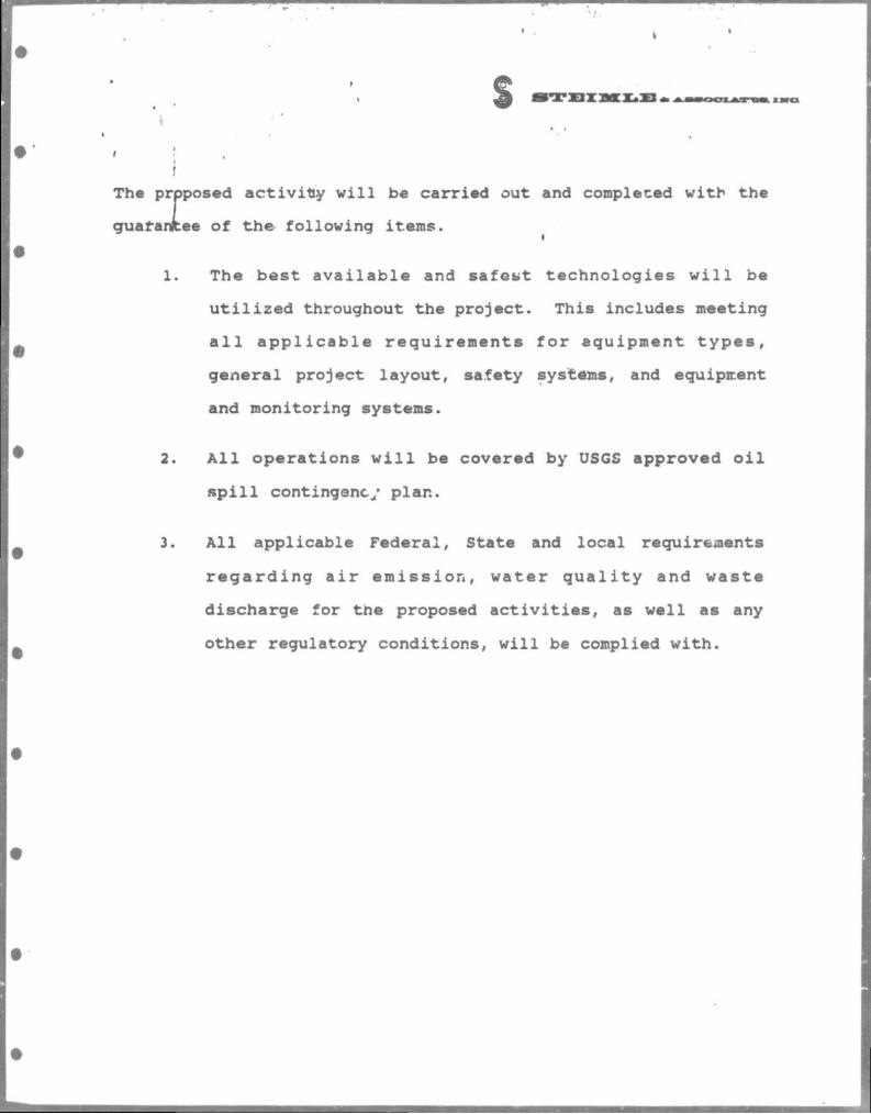
The proposed ac t iv i ty w i l l be carried out and completed with the
guatanfc.ee of the following items.
1. The best a v a i l a b l e and sa fe s t technologies w i l l be
u t i l i z e d throughout the project. This includes meeting
a l l a p p l i c a b l e requirements f o r equipment t y p e s ,
general project layout, safety systems, and equipment
and monitoring systems.
2. A l l operations w i l l be covered by USGS approved o i l
s p i l l contingency plan.
3. A l l applicable Federal , State and local requirements
r e g a r d i n g a i r e m i s s i o n , water q u a l i t y and waste
discharge for tne proposed a c t i v i t i e s , as well as any
other regulatory conditions, w i l l be complied with.
s -T E I M
I,
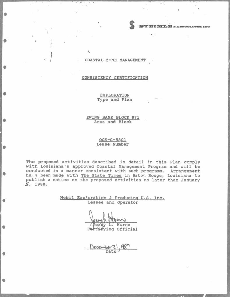
COASTAL ZONE MANAGEMENT
CPPSIgTEECY c w i n c A T I Q N
EXPLORATION Type and Plan
EWING BANK BLOCK 871 Area and Block
OCS-G-5801 Lease Number
The proposed a c t i v i t i e s described in detai l in th is Plan comply with Louisiana's approved Coastal Management Program and w i l l be conducted in a manner consistent with such programs. Arrangement ha . i been made with The State Times in Baton Rouge, Louisiana to publ ish a notice on the proposed a c t i v i t i e s no later than January S , 1988.
Mobil Exploration & Producing U.S. Inc. Lessee and Operator
mrmttmn COAST* B H M H W »S OfFIKO r KT W «s «ua nn. mt vm • 10 JO » 40 i
LOUISIANA COASTAL RESOURCES »TNAL ENVIRONMENTAL •WACT STATEMENT
EWING BANK BLOCK 0 7
0
EXHIBIT I
EWING BANK »_oCK 6 7 I
IN RELATION TO
THE LOUISIANA COASTAL ZONE
STEIMLE A ASSOC, INC EMOmCim. iCOlOOaJTY FIAMNCTS
SPECIALIZING IN JMf ENVIRONMENT"
°™ /z/n/ffr
« .
EWING BANK BLOCK 871
WELL B
+ WELL C WELL A
S C A L E " I "=3000*
!
EXHIBIT 2
REFERENCE : MEPUS EXPLORATION PLAN ANO GEOLOGIC PROGRAM
PROPOSED WELL LOCATIONS
EWING BANK BLOCK 871
S STEIMLE & ASSOC., INC. ENG'NEZRC. ECOLOniSTS. PLANNERS
SPECIALIZING IN THE ENVIRONMENT 3626 AIRLINE HWY. MCTAIRIE. LA TOOQi
°*TE. /Z / /7 /37 \ ̂ w . g j j * I CHK. ev
s r
i. AIR QUALITY STUDY EMISSIONS DATA AND CALCULATIONS
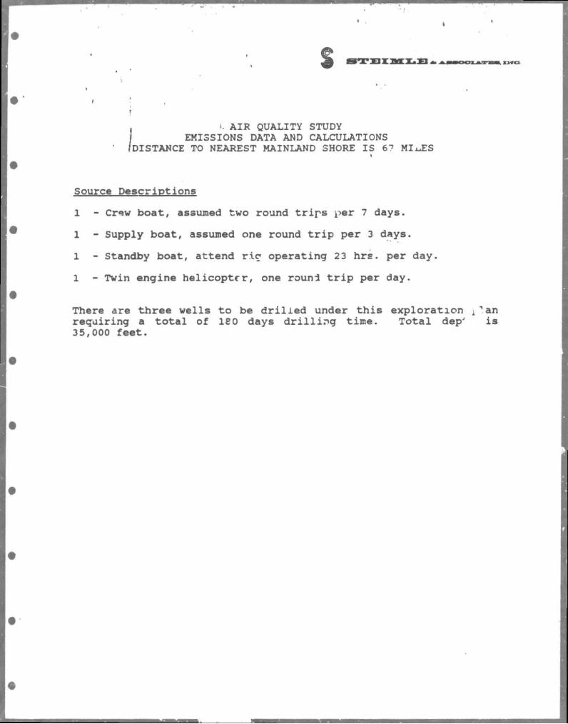
DISTANCE TO NEAREST MAINLAND SHORE IS 67 MIA.ES
Source Descriptions
1 - Crew boat, assumed two round trips per 7 days.
1 - Supply boat, assumed one round trip per 3 days.
1 - Standby boat, attend r i c operating 23 hrs. per day.
1 - Twin engine helicopter, one round trip per day.
There are three wells to be drilled under this exploration A'an requiring a total of 180 days drilling time. Total dep' i s 35,000 feet.
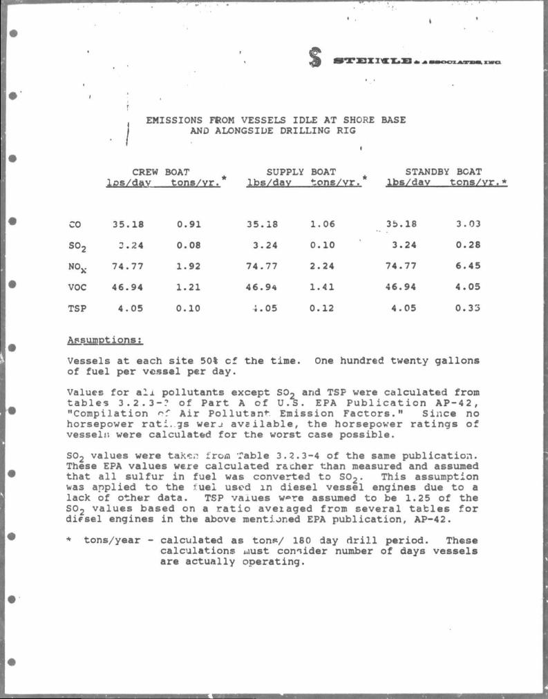
s EMISSIONS FROM VESSELS IDLE AT SHORE BASE
AND ALONGSIDE DRILLING RIG
CREW los/dav
BOAT tons/vr.
SUPPLY lbs/dav
BOAT tons/vr.
STANDBY lbs/dav
BCAT tons/
• CO 35.18 0.91 35.18 1.06 3b.18 3.03
so2 3.24 0.08 3.24 0.10 3.24 0.28
NOx 74.77 1.92 74.77 2.24 74.77 6.45
• VOC 46.94 1.21 46.94 1.41 46.94 4.05
TSP 4.05 0.10 *.05 0.12 4.05 0.33
• Assuror. )tions:
Vessels at each si t e 50% cf the time. One hundred twenty gallons of fuel per vessel per day.
Values for a l i pollutants except SOo and TSF were calculated from tables 3.2.3-? of Part A of U.S. EPA Publication AP-42, "Compilation of Air Pollutant Emission Factors." Since no horsepower rati.gs werj available, the horsepower ratings of vessels; were calculated for the worst case possible.
S02 values were take;? irom Table 3.2.3-4 of the same publication. These EPA values were calculated r&cher than measured and assumed that a l l sulfur in fuel was converted to S0 2. This assumption was applied to the tuel used in diesel vessel engines due to a lack of other data. TSP vaiues w«»re assumed to be 1.25 of the S0 2 values based on a ratio aveiaged froro several tables for difsei engines in the above mentioned EPA publication, AP-42.
* tons/year - calculated as tons/ 180 day d r i l l period. These calculations uust consider number of days vessels are actually operating.
s %
4
i
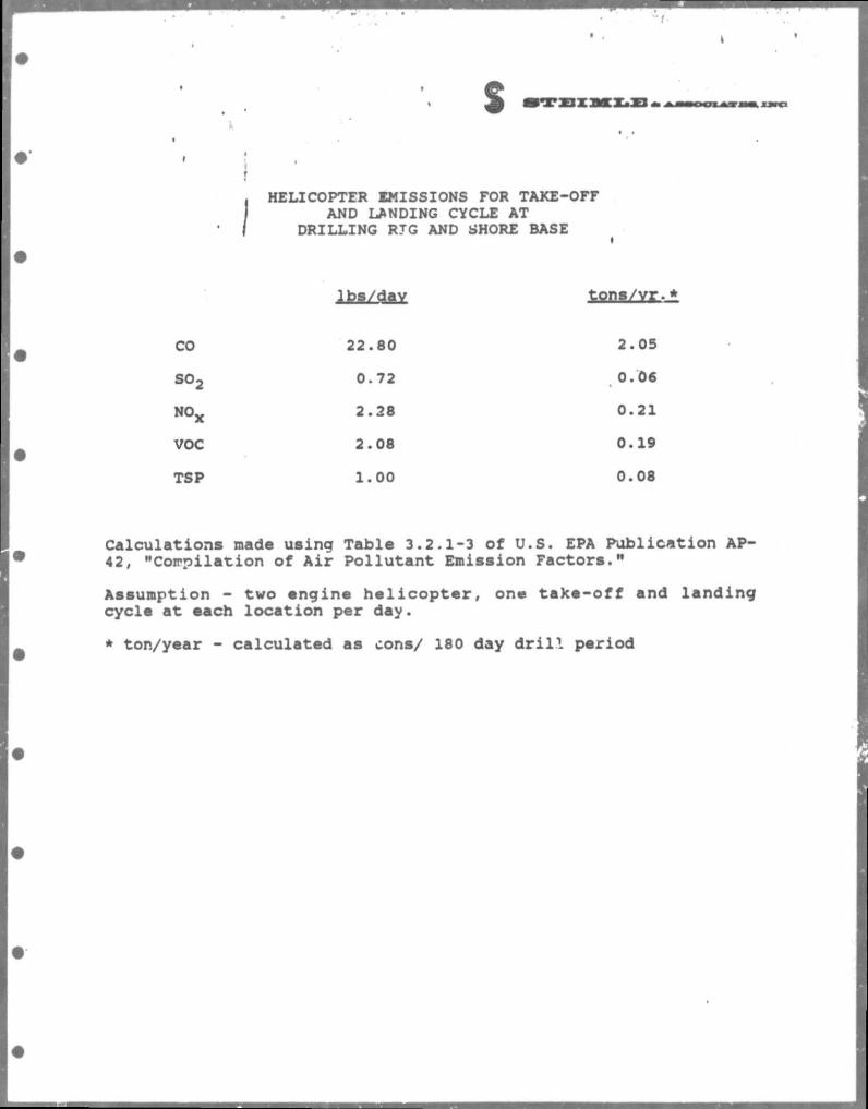
• I HELICOPTER EMISSIONS FOR TAKE-OFF
AND LANDING CYCLE AT DRILLING RTG AND SHORE BASE
lbs/dav
CO 22.80 2.05
S02 0.72 0.06
NOx 2.28 0.21
VOC 2.08 0.19
TSP 1.00 0.08
Calculations made using Table 3.2.1-3 of U.S. EPA Publication AP-42, "Compilation of Air Pollutant Emission Factors.1"
Assumption - two engine h e l i c o p t e r , one take-off and landing cycle at each location per day.
* ton/year - calculated as cons/ 180 day d r i l l period
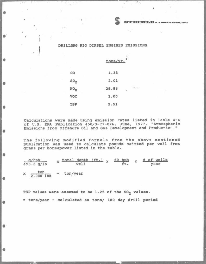
s DRILLING RIG DIESEL ENGINES EMISSIONS
tons/yr.*
CO 4.38
so2 2.01
N0X 29.86
VOC 1.00
TSP 2.51
Calculations were made using emission rates l isted in Table 4-4 of U.S. EPA Publication 450/3-77-026, June, 1977, "Atmospheric Emissions from Offshore Oil and Gas Development and Productic: ."
The fol lowing modified formula from the above mentioned publication was used to calculate pounds emitted per well from grams per horsepower listed in the table.
q/hph x total depth it%.) x v° hPh x f Q f 453.6 g/lb well f t . year
x „ ^ ° n , i - ton/year 2,000 lbs
TSP values were assumed to be 1.25 of the S0 2 values.
* tons/year - calculated as tons/ 180 day d r i l l period
s -X-XJX:
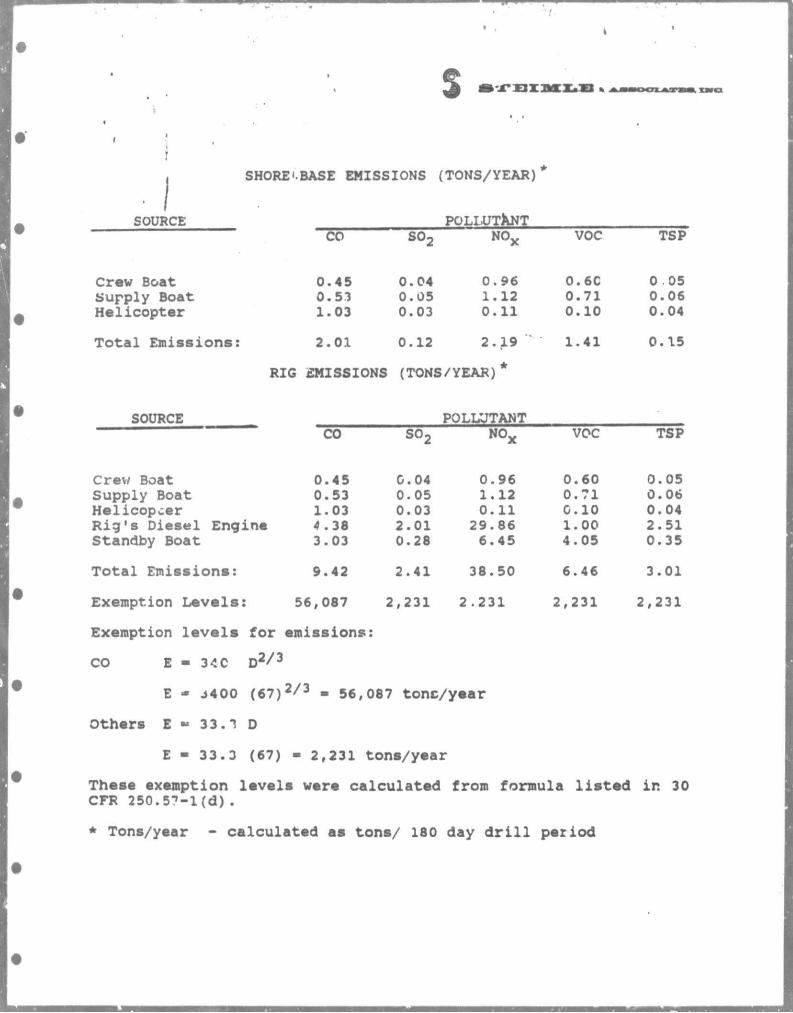
SOURCE
SHORE'.BASE EMISSIONS (TONS/YEAR)
POLLUTANT CO so2
NO x VOC TSP
Crew Boat 0.45 0.04 0.96 0.6C 0 05 Supply Boat 0.53 0.05 1.12 0.71 0.06
• Hel icopter 1.03 0.03 0.11 0.10 0.04
T o t a l Emiss ions : 2.01 0.12 2.19 ' 1.41 0.15
RIG EMISSIONS (TONS/YEAR)*
• SOURCE POLLUTANT CO so2
NO x VOC TSP
Crew Boat 0.45 0.04 0.96 0.60 0.05 Supply Boat 0.53 0.05 1.12 0.71 0. 06 Hel icopter 1.03 0.03 0.11 0.10 0.04 R i g ' 8 Diese l Engine 4 .38 2.01 29.86 1.00 2.51 Standby Boat 3.03 0.28 6.45 4.05 0.35
T o t a l Emiss ions : 9.42 2.41 38.50 6.46 3.01
• Exemption L e v e l s : 56,087 2 ,231 2.231 2,231 2,231
Exemption l e v e l s for emissions:
CO E - 340 D 2 / 3
E - J400 ( 6 7 ) 2 / 3 - 56,087 tone/year
Others E •» 33. T D
E - 33.3 (67) - 2,231 tons/year
These exemption levels were calculated from formula listed in 30 CFR 250.57-l(d) .
* Tons/year - calculated as tons/ 180 day d r i l l period


