Download - 9500 Parts Catalog

8/18/2019 9500 Parts Catalog
http://slidepdf.com/reader/full/9500-parts-catalog 1/84
ENWW Chapter 8 Parts and diagrams 473
8 Parts and diagrams
Chapter contents
Introduction . . . . . . . . . . . . . . . . . . . . . . . . . . . . . . . . . . . . . . . . . . . . . . . . . . . . . . . . . . . . . . . . . 475
Ordering parts. . . . . . . . . . . . . . . . . . . . . . . . . . . . . . . . . . . . . . . . . . . . . . . . . . . . . . . . . . . . 475Customer support information. . . . . . . . . . . . . . . . . . . . . . . . . . . . . . . . . . . . . . . . . . . . . . 475Terminology . . . . . . . . . . . . . . . . . . . . . . . . . . . . . . . . . . . . . . . . . . . . . . . . . . . . . . . . . . . . 476
Unique parts . . . . . . . . . . . . . . . . . . . . . . . . . . . . . . . . . . . . . . . . . . . . . . . . . . . . . . . . . . . . . 476Kits, supplies, accessories, exchange parts, and documentation. . . . . . . . . . . . . . . . . . . . . 479
Hardware identification . . . . . . . . . . . . . . . . . . . . . . . . . . . . . . . . . . . . . . . . . . . . . . . . . . . . . 483Illustrations and parts lists . . . . . . . . . . . . . . . . . . . . . . . . . . . . . . . . . . . . . . . . . . . . . . . . . . . . . . 484
External covers and panels. . . . . . . . . . . . . . . . . . . . . . . . . . . . . . . . . . . . . . . . . . . . . . . . . . 484Left cover assembly . . . . . . . . . . . . . . . . . . . . . . . . . . . . . . . . . . . . . . . . . . . . . . . . . . . . . . . 488Right door assembly . . . . . . . . . . . . . . . . . . . . . . . . . . . . . . . . . . . . . . . . . . . . . . . . . . . . . . . 489Internal components (1 of 9). . . . . . . . . . . . . . . . . . . . . . . . . . . . . . . . . . . . . . . . . . . . . . . . . 490Internal components (2 of 9). . . . . . . . . . . . . . . . . . . . . . . . . . . . . . . . . . . . . . . . . . . . . . . . . 492
Internal components (3 of 9). . . . . . . . . . . . . . . . . . . . . . . . . . . . . . . . . . . . . . . . . . . . . . . . . 494Internal components (4 of 9). . . . . . . . . . . . . . . . . . . . . . . . . . . . . . . . . . . . . . . . . . . . . . . . . 496Internal components (5 of 9). . . . . . . . . . . . . . . . . . . . . . . . . . . . . . . . . . . . . . . . . . . . . . . . . 498Internal components (6 of 9). . . . . . . . . . . . . . . . . . . . . . . . . . . . . . . . . . . . . . . . . . . . . . . . . 500Internal components (7 of 9). . . . . . . . . . . . . . . . . . . . . . . . . . . . . . . . . . . . . . . . . . . . . . . . . 502
Internal components (8 of 9). . . . . . . . . . . . . . . . . . . . . . . . . . . . . . . . . . . . . . . . . . . . . . . . . 504Internal components (9 of 9). . . . . . . . . . . . . . . . . . . . . . . . . . . . . . . . . . . . . . . . . . . . . . . . . 506Registration drive assembly . . . . . . . . . . . . . . . . . . . . . . . . . . . . . . . . . . . . . . . . . . . . . . . . . 508
Process cartridge drive assembly (image drum drive) . . . . . . . . . . . . . . . . . . . . . . . . . . . . . 509Toner cartridge drive assembly (print cartridge drive) . . . . . . . . . . . . . . . . . . . . . . . . . . . . . 510Fuser drive assembly . . . . . . . . . . . . . . . . . . . . . . . . . . . . . . . . . . . . . . . . . . . . . . . . . . . . . . 512Cassette assembly . . . . . . . . . . . . . . . . . . . . . . . . . . . . . . . . . . . . . . . . . . . . . . . . . . . . . . . . 514Paper pickup assembly (1 of 3). . . . . . . . . . . . . . . . . . . . . . . . . . . . . . . . . . . . . . . . . . . . . . . 516Paper pickup assembly (2 of 3). . . . . . . . . . . . . . . . . . . . . . . . . . . . . . . . . . . . . . . . . . . . . . . 518Paper pickup assembly (3 of 3). . . . . . . . . . . . . . . . . . . . . . . . . . . . . . . . . . . . . . . . . . . . . . . 520Manual feed pickup assembly (tray 1) (1 of 2) . . . . . . . . . . . . . . . . . . . . . . . . . . . . . . . . . . . 522
Manual feed pickup assembly (tray 1) (2 of 2) . . . . . . . . . . . . . . . . . . . . . . . . . . . . . . . . . . . 524Registration assembly. . . . . . . . . . . . . . . . . . . . . . . . . . . . . . . . . . . . . . . . . . . . . . . . . . . . . . 526Secondary transfer assembly (T2) (1 of 2) . . . . . . . . . . . . . . . . . . . . . . . . . . . . . . . . . . . . . . 528Secondary transfer assembly (T2) (2 of 2) . . . . . . . . . . . . . . . . . . . . . . . . . . . . . . . . . . . . . . 530Delivery feed assembly. . . . . . . . . . . . . . . . . . . . . . . . . . . . . . . . . . . . . . . . . . . . . . . . . . . . . 531Face down delivery assembly . . . . . . . . . . . . . . . . . . . . . . . . . . . . . . . . . . . . . . . . . . . . . . . . 532Delivery cover assembly . . . . . . . . . . . . . . . . . . . . . . . . . . . . . . . . . . . . . . . . . . . . . . . . . . . . 533Fuser assembly. . . . . . . . . . . . . . . . . . . . . . . . . . . . . . . . . . . . . . . . . . . . . . . . . . . . . . . . . . . 534
PCB assemblies . . . . . . . . . . . . . . . . . . . . . . . . . . . . . . . . . . . . . . . . . . . . . . . . . . . . . . . . . . 535

8/18/2019 9500 Parts Catalog
http://slidepdf.com/reader/full/9500-parts-catalog 2/84
474 Chapter 8 Parts and diagrams ENWW
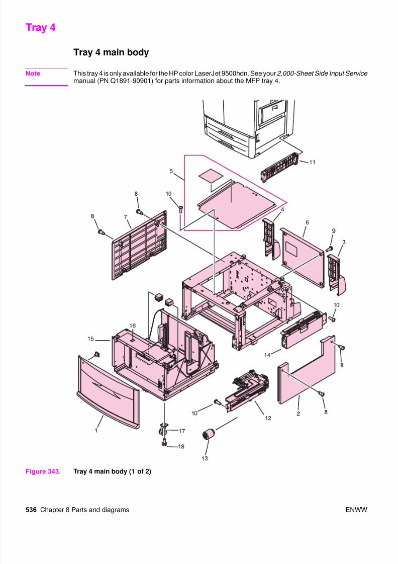
Tray 4 . . . . . . . . . . . . . . . . . . . . . . . . . . . . . . . . . . . . . . . . . . . . . . . . . . . . . . . . . . . . . . . . . . . . . 536Tray 4 main body . . . . . . . . . . . . . . . . . . . . . . . . . . . . . . . . . . . . . . . . . . . . . . . . . . . . . . . . . 536Tray 4 drive assembly. . . . . . . . . . . . . . . . . . . . . . . . . . . . . . . . . . . . . . . . . . . . . . . . . . . . . . 540Tray 4 PCA location . . . . . . . . . . . . . . . . . . . . . . . . . . . . . . . . . . . . . . . . . . . . . . . . . . . . . . . 541
Pedestal . . . . . . . . . . . . . . . . . . . . . . . . . . . . . . . . . . . . . . . . . . . . . . . . . . . . . . . . . . . . . . . . . . . 542Pedestal main body (1 of 2) . . . . . . . . . . . . . . . . . . . . . . . . . . . . . . . . . . . . . . . . . . . . . . . . . 542Pedestal main body (2 of 2) . . . . . . . . . . . . . . . . . . . . . . . . . . . . . . . . . . . . . . . . . . . . . . . . . 543
Master parts lists . . . . . . . . . . . . . . . . . . . . . . . . . . . . . . . . . . . . . . . . . . . . . . . . . . . . . . . . . . . . 544Alphabetical parts l ist . . . . . . . . . . . . . . . . . . . . . . . . . . . . . . . . . . . . . . . . . . . . . . . . . . . . . . 544
Numerical parts list . . . . . . . . . . . . . . . . . . . . . . . . . . . . . . . . . . . . . . . . . . . . . . . . . . . . . . . 550

8/18/2019 9500 Parts Catalog
http://slidepdf.com/reader/full/9500-parts-catalog 3/84
ENWW Chapter 8 Parts and diagrams 475
Introduction
Note This chapter describes assemblies and components for the HP color LaserJet 9500 printer and theprint engine portion of the HP color LaserJet 9500mfp. See the HP Scanner/ADF Service Manual forthe HP LaserJet 9000mfp/9000Lmfp/9040mfp/9050mfp/9500mfp ( PN C8549-90955)
for assemblyillustrations and part numbers for components that are unique to the MFP.
The figures in this chapter illustrate the major subassemblies in the printer and the MFP print engine
as well as their component parts. Parts shown in magenta are field replacable units (FRUs). A tableaccompanies each exploded-view diagram. Each table lists the item number for represented parts,the associated part number for the item (if it can be ordered), the quantity, and a description of thepart. Parts that are listed as not orderable are available by ordering the higher-level assembly orFRU.
Note When looking for an electrical part, pay careful attention to the voltage listed in the description columnto ensure that the part number selected is for the correct printer model.
Ordering parts
All standard part numbers listed are stocked and can be ordered from HP’s Customer Services andSupport Organization. The following website allows you to search for HP product parts using the HPproduct name or model number, part number, or by choosing an HP product from a list.
www.partsurfer.hp.com
To order parts, go to
www.hp.com/buyparts
Consumables and accessories like those listed in table 84 can be ordered from Hewlett-Packard.
Supplies, accessories, and consumables can be ordered from the following websites:
North America: www.hp.com/sbso/product/supplies
Canada: www.hp.ca/catalog/supplies
Europe: www.hp.com/go/supplies
Asia Pacific: www.hp.com/paper
Customer support information
Before visiting the printer support website (URL: www.hp.com/support/lj9500) or the CustomerServices and Support Organization (URLs listed above), obtain the following information and printthe specified diagnostic pages.
Printer model-found on the upper-right corner of the front doors of the printer.
Serial number-found inside the front doors, in the lower-right corner.
Configuration page, EIO Jetdirect card page, event log.

8/18/2019 9500 Parts Catalog
http://slidepdf.com/reader/full/9500-parts-catalog 4/84
476 Chapter 8 Parts and diagrams ENWW
Terminology
Unique parts
Some parts are unique to the HP CLJ 9500 printer or to the HP CLJ 9500mfp. Use table 81 to
determine if the part required is unique to the printer model being serviced.
Table 81. Parts that are unique to the HP color LaserJet 9500 or 9500mfp
Table 80. Term decoder
HP term Parts listing Definition
Image drum P-crg Process cartridge (carrier, OPC, charge roller, developer sleeve)
Print cartridge T-crg Toner cartridge
Toner collection bottle Waste toner bottle assembly Receptacle for waste toner from EP process
Image transfer roller Transfer roller assembly Secondary transfer roller (T2)
Image transfer belt Intermediate transfer belt (ITB)
assembly
Image transfer belt (ITB)
Post charger Not orderable (part of the ITB) Corona wire to faci li tate secondary transfer
Transfer cleaner ITB cleaner assembly ITB cleaning blade
Ref Description Part number Qty.
Figure 312; 1 Cover, left upper (HP CLJ 9500 only) RB2-7336-000CN 1
Figure 312; 24 Tray, face-up delivery (HP CLJ 9500 only) RB2-5690-000CN 1
Figure 313; 12 Tray, delivery movable (HP CLJ 9500 only) RB2-7341-000CN 1
Figure 313; 13 Cover, top right (HP CLJ 9500 only) RB2-7321-000CN 1
Figure 313; 15 Display, panel assembly (control panel) (HP CLJ 9500 only) RG5-6115-030CN 1
Figure 313; 15 Display, panel assembly (control panel) (HP CLJ 9500mfp only) 5851-1838 1
Figure 313; 17 Cover, top left assembly (HP LJ 9500 only) RG5-6112-000CN 1
Figure 339; all Face-down delivery assembly (use this part number to order the entire
assembly) (HP CLJ 9500 only)
RG5-6017-000CN 1
Figure 321; 19 Cable, right upper crossmember (J1701R, J3015D, J3013, J3085)
(HP CLJ 9500 only)
RG5-5943-000CN 1
Figure 321; 19 Cable, right upper crossmember (HP CLJ 9500mfp only) RG5-5974-000CN 1
Figure 324; 19 Cable, rear upper cable (HP CLJ 9500 only) RG5-5920-000CN 1
Figure 324; 19 Cable, rear upper cable (HP CLJ 9500mfp only) RG5-5990-000CN 1
Figure 338; all Delivery feed assembly (use this part number to order the entire
assembly; SL2, J3069) (HP CLJ 9500 only)
RG5-6150-000CN 1
Figure 311; 2 Delivery feed assembly (use this part number to order the entireassembly) (HP CLJ 9500mfp only)
RG5-6190-000CN 1
Figure 340; all Delivery cover assembly (use this part number to order the entire
assembly) (HP CLJ 9500 only)
RG5-6151-000CN 1
Figure 311; 1 Delivery cover assembly (use this part number to order the entire
assembly) (HP CLJ 9500mfp only)
RG5-6191-000CN
Figure 340; 2 Fan (HP CLJ 9500 only) RH7-1546-000CN 2
Figure 310; 1 Guide, feed (HP CLJ 9500mfp only) RB2-7376-000CN 1
NA Cable, AC (HP CLJ 9500mfp only) RG5-5991-000CN 1
NA Cable, grounding (HP CLJ 9500mfp only) RG5-5992-000CN 1

8/18/2019 9500 Parts Catalog
http://slidepdf.com/reader/full/9500-parts-catalog 5/84
ENWW Chapter 8 Parts and diagrams 477
Figure 310. Parts that are unique to the MFP (1 of 2)
1
Table 82. Parts that are unique to the MFP (1 of 2)
Ref Description Part number Qty
Figure 310; 1 Guide, feed (HP CLJ 9500mfp only) RB2-7376-000CN 1

8/18/2019 9500 Parts Catalog
http://slidepdf.com/reader/full/9500-parts-catalog 6/84

8/18/2019 9500 Parts Catalog
http://slidepdf.com/reader/full/9500-parts-catalog 7/84
ENWW Chapter 8 Parts and diagrams 479
Kits, supplies, accessories, exchange parts, and documentation
Note If item does not have a product number, use the service-part number to order that item.
Table 84. Kits and supplies
Item Product
Number
Service
part-number
Description
Print cartridge, black C8550A C8550-67901 Replacement print cartridge
Print cartridge, cyan C8551A C8551-67901 Replacement print cartridge
Print cartridge, yellow C8552A C8552-67901 Replacement print cartridge
Print cartridge, magenta C8553A C8553-67901 Replacement print cartridge
Image drum, black C8560A C8560-67901 Replacement image drum
Image drum, cyan C8561A C8561-67901 Replacement image drum
Image drum, yellow C8562A C8562-67901 Replacement image drum
Image drum, magenta C8563A C8563-67901 Replacement image drum
Image transfer Kit C8555A C8555-67901 One image transfer belt, one imagetransfer roller, nine paper rollers,
and one ozone filter
Image cleaning kit C8554A C8554-67901 One air filter, one transfer cleaner,
and one toner collection bottle
Fuser kit C8556A RG5-6098-000CN new
C8546-69007 exchange
One fuser assembly
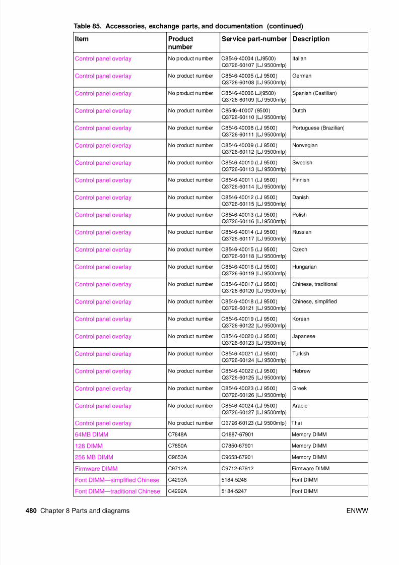
Table 85. Accessories, exchange parts, and documentation
Item Product
number
Service part-number Description
Staple cartridge for stapler/ stacker
C8091A C8085-67901 Replacement cartridge
Staple cartridge for multifunction
finisher
C8092A C8088-60541 Replacement cartridge
Intermediate transfer belt (ITB)
assembly
No product number RG5-6400-030CN new
C8546-69002 exchange
Entire assembly
Cartridge drive assembly No product number. RG5-6188-030CN new
C8546-69006 exchange
Entire assembly
Power supply 110 V No product number C8546-69003 exchange PCA assembly
Power supply 220 V No product number C8546-69004 exchange PCA assembly
Formatter assembly (LJ 9500) No product number C8546-67911 newC8546-69001 exchange Does not include memory,firmware, or EIO card
Formatter assembly (LJ9500mfp) Q5915A Q5915-67901 new
Q5915-69001 exchange
Does not include memory,
firmware, or EIO card
DC controller No product number C8546-67906 new
C8546-69005 exchange
PCA
16 MB DIMM C9712CA C9712-67907 Flash firmware DIMM for
formatter
Control panel overlay No product number C8546-40002 (LJ9500)
Q3726-60105 (LJ 9500mfp)
English
Control panel overlay No product number C8546-40003 (LJ9500)
Q3726-60106 (LJ 9500mfp)
French (European)
8/18/2019 9500 Parts Catalog
http://slidepdf.com/reader/full/9500-parts-catalog 8/84
480 Chapter 8 Parts and diagrams ENWW
Control panel overlay No product number C8546-40004 (LJ9500)
Q3726-60107 (LJ 9500mfp)
Italian
Control panel overlay No product number C8546-40005 (LJ 9500)
Q3726-60108 (LJ 9500mfp)
German
Control panel overlay No product number C8546-40006 LJ(9500)
Q3726-60109 (LJ 9500mfp)
Spanish (Castilian)
Control panel overlay No product number C8546-40007 (9500)
Q3726-60110 (LJ 9500mfp)
Dutch
Control panel overlay No product number C8546-40008 (LJ 9500)
Q3726-60111 (LJ 9500mfp)
Portuguese (Brazilian)
Control panel overlay No product number C8546-40009 (LJ 9500)
Q3726-60112 (LJ 9500mfp)
Norwegian
Control panel overlay No product number C8546-40010 (LJ 9500)
Q3726-60113 (LJ 9500mfp)
Swedish
Control panel overlay No product number C8546-40011 (LJ 9500)
Q3726-60114 (LJ 9500mfp)
Finnish
Control panel overlay No product number C8546-40012 (LJ 9500)Q3726-60115 (LJ 9500mfp)
Danish
Control panel overlay No product number C8546-40013 (LJ 9500)
Q3726-60116 (LJ 9500mfp)
Polish
Control panel overlay No product number C8546-40014 (LJ 9500)
Q3726-60117 (LJ 9500mfp)
Russian
Control panel overlay No product number C8546-40015 (LJ 9500)
Q3726-60118 (LJ 9500mfp)
Czech
Control panel overlay No product number C8546-40016 (LJ 9500)
Q3726-60119 (LJ 9500mfp)
Hungarian
Control panel overlay No product number C8546-40017 (LJ 9500)
Q3726-60120 (LJ 9500mfp)
Chinese, traditional
Control panel overlay No product number C8546-40018 (LJ 9500)
Q3726-60121 (LJ 9500mfp)
Chinese, simplified
Control panel overlay No product number C8546-40019 (LJ 9500)
Q3726-60122 (LJ 9500mfp)
Korean
Control panel overlay No product number C8546-40020 (LJ 9500)
Q3726-60123 (LJ 9500mfp)
Japanese
Control panel overlay No product number C8546-40021 (LJ 9500)
Q3726-60124 (LJ 9500mfp)
Turkish
Control panel overlay No product number C8546-40022 (LJ 9500)
Q3726-60125 (LJ 9500mfp)
Hebrew
Control panel overlay No product number C8546-40023 (LJ 9500)
Q3726-60126 (LJ 9500mfp)
Greek
Control panel overlay No product number C8546-40024 (LJ 9500)
Q3726-60127 (LJ 9500mfp)
Arabic
Control panel overlay No product number Q3726-60123 (LJ 9500mfp) Thai
64MB DIMM C7848A Q1887-67901 Memory DIMM
128 DIMM C7850A C7850-67901 Memory DIMM
256 MB DIMM C9653A C9653-67901 Memory DIMM
Firmware DIMM C9712A C9712-67912 Firmware DIMM
Font DIMM—simplified Chinese C4293A 5184-5248 Font DIMM
Font DIMM—traditional Chinese C4292A 5184-5247 Font DIMM
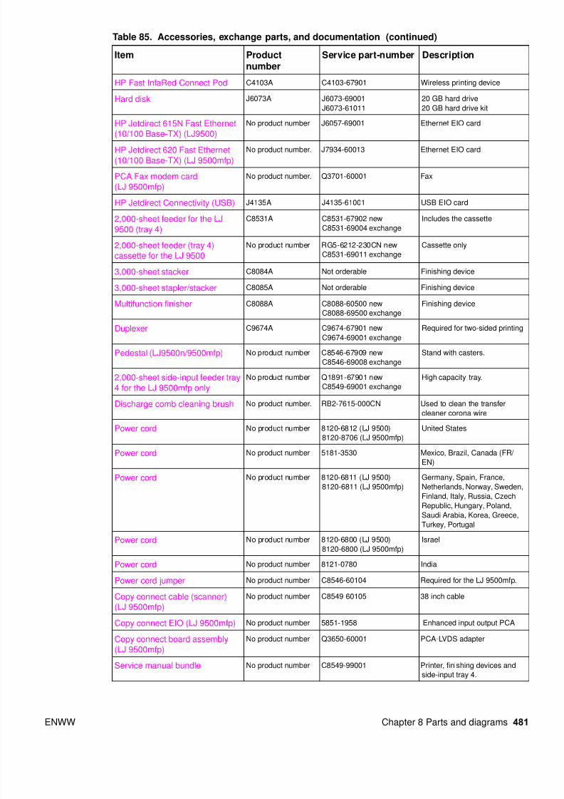
Table 85. Accessories, exchange parts, and documentation (continued)
Item Productnumber
Service part-number Description
8/18/2019 9500 Parts Catalog
http://slidepdf.com/reader/full/9500-parts-catalog 9/84
ENWW Chapter 8 Parts and diagrams 481
HP Fast InfaRed Connect Pod C4103A C4103-67901 Wireless printing device
Hard disk J6073A J6073-69001
J6073-61011
20 GB hard drive
20 GB hard drive kit
HP Jetdirect 615N Fast Ethernet
(10/100 Base-TX) (LJ9500)
No product number J6057-69001 Ethernet EIO card
HP Jetdirect 620 Fast Ethernet
(10/100 Base-TX) (LJ 9500mfp)
No product number. J7934-60013 Ethernet EIO card
PCA Fax modem card
(LJ 9500mfp)
No product number. Q3701-60001 Fax
HP Jetdirect Connectivity (USB) J4135A J4135-61001 USB EIO card
2,000-sheet feeder for the LJ
9500 (tray 4)
C8531A C8531-67902 new
C8531-69004 exchange
Includes the cassette
2,000-sheet feeder (tray 4)
cassette for the LJ 9500
No product number RG5-6212-230CN new
C8531-69011 exchange
Cassette only
3,000-sheet stacker C8084A Not orderable Finishing device
3,000-sheet stapler/stacker C8085A Not orderable Finishing device
Multifunction finisher C8088A C8088-60500 new
C8088-69500 exchange
Finishing device
Duplexer C9674A C9674-67901 new
C9674-69001 exchange
Required for two-sided printing
Pedestal (LJ9500n/9500mfp) No product number C8546-67909 new
C8546-69008 exchange
Stand with casters.
2,000-sheet side-input feeder tray
4 for the LJ 9500mfp only
No product number Q1891-67901 new
C8549-69001 exchange
High capacity tray.
Discharge comb cleaning brush No product number. RB2-7615-000CN Used to clean the transfer
cleaner corona wire
Power cord No product number 8120-6812 (LJ 9500)
8120-8706 (LJ 9500mfp)
United States
Power cord No product number 5181-3530 Mexico, Brazil, Canada (FR/
EN)
Power cord No product number 8120-6811 (LJ 9500)
8120-6811 (LJ 9500mfp)
Germany, Spain, France,
Netherlands, Norway, Sweden,
Finland, Italy, Russia, Czech
Republic, Hungary, Poland,
Saudi Arabia, Korea, Greece,
Turkey, Portugal
Power cord No product number 8120-6800 (LJ 9500)
8120-6800 (LJ 9500mfp)
Israel
Power cord No product number 8121-0780 India
Power cord jumper No product number C8546-60104 Required for the LJ 9500mfp.
Copy connect cable (scanner)
(LJ 9500mfp)
No product number C8549-60105 38 inch cable
Copy connect EIO (LJ 9500mfp) No product number 5851-1958 Enhanced input output PCA
Copy connect board assembly
(LJ 9500mfp)
No product number Q3650-60001 PCA-LVDS adapter
Service manual bundle No product number C8549-99001 Printer, finishing devices and
side-input tray 4.
Table 85. Accessories, exchange parts, and documentation (continued)
Item Productnumber
Service part-number Description

8/18/2019 9500 Parts Catalog
http://slidepdf.com/reader/full/9500-parts-catalog 10/84
482 Chapter 8 Parts and diagrams ENWW
Training kit for HP color LaserJet
9500/9500mfp printer
No product number C8546-60109 CD- based service training
materials
User guide Electronic versions ready to print at:
www.hp.com/support/lj9500
Mini-manual that goes inside of
the right door of the HP color
LaserJet 9500 series printer
HP color LaserJet 9500 Series
Printer Use guide and User
reference guide
Electronic versions ready to print at:
www.hp.com/support/lj9500
Electronic versions of the user
guide and the user reference
guide.
HP color LaserJet 9500mfp
Printer Use guide and User
reference guide
Electronic versions ready to print at:
www.hp.com/support/clj9500mfp
Electronic versions of the user
guide and the user reference
guide.
Table 85. Accessories, exchange parts, and documentation (continued)
Item Productnumber
Service part-number Description

8/18/2019 9500 Parts Catalog
http://slidepdf.com/reader/full/9500-parts-catalog 11/84
ENWW Chapter 8 Parts and diagrams 483
Hardware identification
Table 86. Common hardwareExample Type and uses
Long aluminum finish (M3 by 8)
• Plastic to sheet metal
• Long-reach sheet metal (P-cartridge motor assembly)
Short brass finish (M3 by 6)
• Sheet metal to sheet metal
Short black finish (M3 by 8)
• Laser/scanner assemblies
Self-threading brass finish (M4)
• Sheet metal to plastic
Table 87. Common torque values
Material HP recommended torque value
Plastic to metal 5.5 pounds per inch
Metal to metal 10 pounds per inch
PCBA 5.5 pounds per inc.
Plastic to plastic 5.5 pounds per inc.

8/18/2019 9500 Parts Catalog
http://slidepdf.com/reader/full/9500-parts-catalog 12/84
484 Chapter 8 Parts and diagrams ENWW
Illustrations and parts lists
The following illustration and parts tables show the field replaceable units (FRUs). Two tables at theend of this chapter list all of the parts shown in this chapter. Both tables also contain the figurenumbers in this chapter that show the parts.
Note Parts shown in magenta are FRUs. Other parts are not service-replaceable. Callout numbers that arefollowed by a “T” indicate the number of teeth on the specified gear.
External covers and panels
Figure 312. External covers and panels (1 of 2)
2
25
24 1
16
3
26
4
6
7
18
19
2
See page 533.
See page 488.

8/18/2019 9500 Parts Catalog
http://slidepdf.com/reader/full/9500-parts-catalog 13/84
ENWW Chapter 8 Parts and diagrams 485
Table 88. External covers and panels (1 of 2)
Ref Description Part number Qty
Figure 312; 1 Cover, left upper (HP CLJ 9500 only) RB2-7336-000CN 1
Figure 312; 2 Cap, cover Not orderable 2
Figure 312; 3 Cover, left lower RB2-5687-000CN 1
Figure 312; 4 Cover, left front RB2-7335-000CN 1
Figure 312; 6 Cover, front right RB2-5682-000CN 1
Figure 312; 7 Cover, front left RB2-5683-000CN 1
Figure 312; 16 Cover, left back assembly RG5-6111-000CN 1
Figure 312; 18 Door, front right assembly RG5-6113-000CN 1
Figure 312; 19 Door, front left assembly RG5-6114-020CN 1
Figure 312; 24 Tray, face-up delivery (HP CLJ 9500 only) RB2-5690-000CN 1
Figure 312; 25 Label, outlet 110 V
Label, outlet 220 V
Not orderable
Not orderable
1
1
Figure 312; 26 Tongs, jam removal RF5-3535-000CN 1
8/18/2019 9500 Parts Catalog
http://slidepdf.com/reader/full/9500-parts-catalog 14/84
486 Chapter 8 Parts and diagrams ENWW
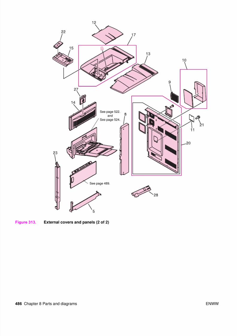
Figure 313. External covers and panels (2 of 2)
See page 522.
and
See page 524.
See page 489.
8/18/2019 9500 Parts Catalog
http://slidepdf.com/reader/full/9500-parts-catalog 15/84
ENWW Chapter 8 Parts and diagrams 487
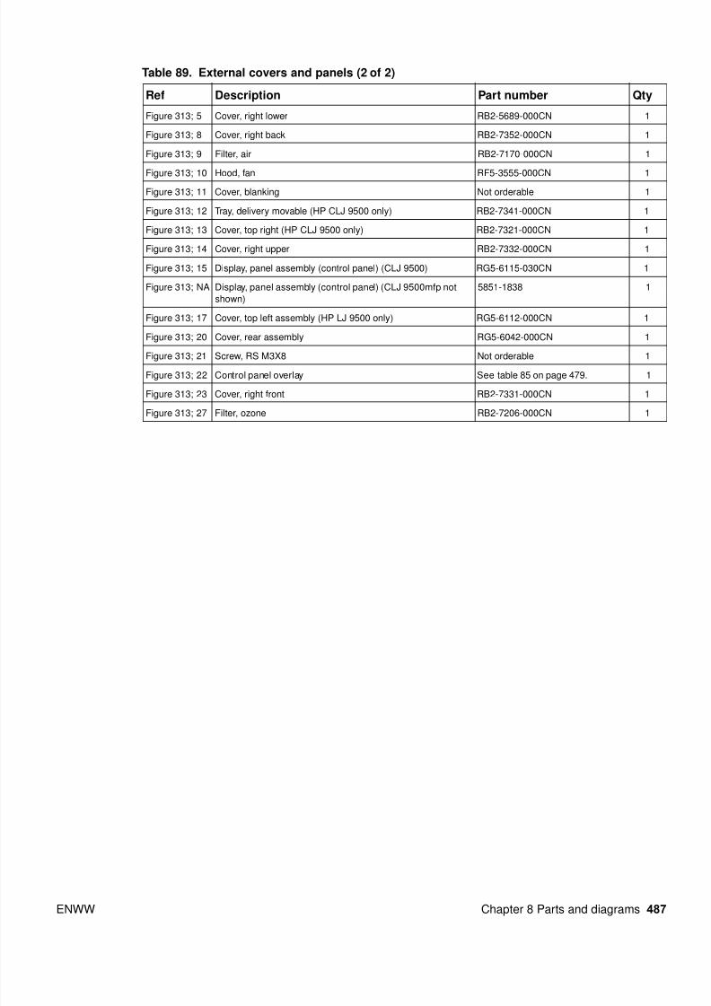
Table 89. External covers and panels (2 of 2)
Ref Description Part number Qty
Figure 313; 5 Cover, right lower RB2-5689-000CN 1
Figure 313; 8 Cover, right back RB2-7352-000CN 1
Figure 313; 9 Filter, air RB2-7170-000CN 1
Figure 313; 10 Hood, fan RF5-3555-000CN 1
Figure 313; 11 Cover, blanking Not orderable 1
Figure 313; 12 Tray, delivery movable (HP CLJ 9500 only) RB2-7341-000CN 1
Figure 313; 13 Cover, top right (HP CLJ 9500 only) RB2-7321-000CN 1
Figure 313; 14 Cover, right upper RB2-7332-000CN 1
Figure 313; 15 Display, panel assembly (control panel) (CLJ 9500) RG5-6115-030CN 1
Figure 313; NA Display, panel assembly (control panel) (CLJ 9500mfp not
shown)
5851-1838 1
Figure 313; 17 Cover, top left assembly (HP LJ 9500 only) RG5-6112-000CN 1
Figure 313; 20 Cover, rear assembly RG5-6042-000CN 1
Figure 313; 21 Screw, RS M3X8 Not orderable 1
Figure 313; 22 Control panel overlay See table 85 on page 479. 1
Figure 313; 23 Cover, right front RB2-7331-000CN 1
Figure 313; 27 Filter, ozone RB2-7206-000CN 1

8/18/2019 9500 Parts Catalog
http://slidepdf.com/reader/full/9500-parts-catalog 16/84
488 Chapter 8 Parts and diagrams ENWW
Left cover assembly
Figure 314. Left cover assembly
Table 90. Left cover assembly
Ref Description Part number Qty
Figure 314; all Cover, left assembly RG5-6149-000CN 1
Figure 314; 1 Dampener, left cover assembly RG5-6185-000CN 1

8/18/2019 9500 Parts Catalog
http://slidepdf.com/reader/full/9500-parts-catalog 17/84
ENWW Chapter 8 Parts and diagrams 489
Right door assembly
Figure 315. Right door assembly
Table 91. Right door assemblyRef Description Part number Qty
Figure 315; all Door, right assembly RG5-6108-000CN 1

8/18/2019 9500 Parts Catalog
http://slidepdf.com/reader/full/9500-parts-catalog 18/84
490 Chapter 8 Parts and diagrams ENWW
Internal components (1 of 9)
Figure 316. Internal components (1 of 9)

8/18/2019 9500 Parts Catalog
http://slidepdf.com/reader/full/9500-parts-catalog 19/84
ENWW Chapter 8 Parts and diagrams 491
Table 92. Internal components (1 of 9)
Ref Description Part number Qty
Figure 316; 1 Cover, inner left upper Not orderable 1
Figure 316; 2 Cover, inner left lower Not orderable 1
Figure 316; 3 Cover, inner right upper Not orderable 1
Figure 316; 4 Cover, inner right lower assembly Not orderable 1
Figure 316; 5 Cover, inner Not orderable 1
Figure 316; 6 Waste toner sensor assembly (J1402, J1403) RG5-6038-000CN 1
Figure 316; 7 Waste toner bottle assembly RG5-6040-020CN 1
Figure 316; 8 Toner cartridge lever assembly RG5-6121-000CN 4
Figure 316; 9 Screw, RS M3X8 Not orderable 11
Figure 316; 10 ITB cleaner assembly RG5-6041-040CN 1
Figure 316; 11 Waste toner connecting cable (J1701L, J3018L) Not orderable 1
Figure 316; 12 Screw, M4X6 Not orderable 1
Figure 316; 13 Tray, catch RB2-7207-000CN 1
Figure 316; 14 Cover, scanner Not orderable 1
Figure 316; 15 Cover, pickup cable Not orderable 1
Figure 316; 16 Cable, support left Not orderable 1
Figure 316; 17 Cable support right Not orderable 1
Figure 316; 18 Screw, RS M3X6 Not orderable 5
8/18/2019 9500 Parts Catalog
http://slidepdf.com/reader/full/9500-parts-catalog 20/84
492 Chapter 8 Parts and diagrams ENWW
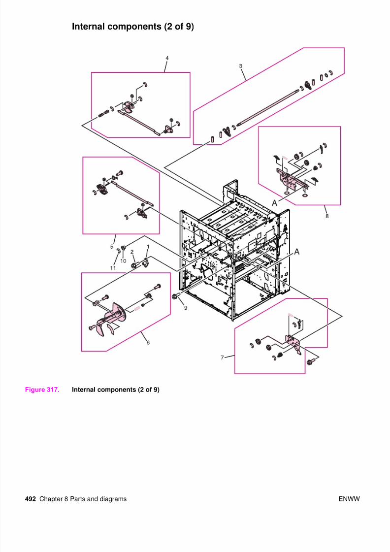
Internal components (2 of 9)
Figure 317. Internal components (2 of 9)

8/18/2019 9500 Parts Catalog
http://slidepdf.com/reader/full/9500-parts-catalog 21/84
ENWW Chapter 8 Parts and diagrams 493
Table 93. Internal components (2 of 9)
Ref Description Part number Qty
Figure 317; 1 Plate, mount Not orderable 1
Figure 317; 2 Screw, RS M3X12 Not orderable 2
Figure 317; 3 Soft link shaft assembly RG5-6122-000CN 1
Figure 317; 4 Lift link front assembly RG5-6131-000CN 1
Figure 317; 5 Lift link rear assembly RG5-6132-000CN 1
Figure 317; 6 Lever assembly RG5-6134-020CN 1
Figure 317; 7 Link rear unit RG5-6147-000CN 1
Figure 317; 8 Transfer link front assembly RG5-6146-000CN 1
Figure 317; 9 Screw, RS M3X6 Not orderable 11
Figure 317; 10 Bushing Not orderable 1
Figure 317; 11 Ring, E Not orderable 1

8/18/2019 9500 Parts Catalog
http://slidepdf.com/reader/full/9500-parts-catalog 22/84
494 Chapter 8 Parts and diagrams ENWW
Internal components (3 of 9)
Figure 318. Internal components (3 of 9)
See page 512.
See page 532.
See page 531.
See page 534.

8/18/2019 9500 Parts Catalog
http://slidepdf.com/reader/full/9500-parts-catalog 23/84
ENWW Chapter 8 Parts and diagrams 495
Table 94. Internal components (3 of 9)
Ref Description Part number Qty
Figure 318; 1 Mount, positioning Not orderable 1
Figure 318; 2 Intermediate transfer belt (ITB) assembly RG5-6180-080CN new
C8546-69002 exchange
1
Figure 318; 3 Screw, TP M4X8 Not orderable 2
Figure 318; 4 Mount, dampener RB2-5570-020CN 2
Figure 318; 5 Main fuser front guide assembly RG9-1595-000CN 1
Figure 318; 6 Sub fuser front guide assembly RG9-1596-000CN 1
Figure 318; 7 Screw, with washer M4X6 Not orderable 1
Figure 318; 8 Plate, feeder support Not orderable 1
Figure 318; 9 Plate, duplexing support Not orderable 1
Figure 318; 10 Plate, fuser positioning Not orderable 1
Figure 318; 11 Mount, lower fuser sensor Not orderable 1
Figure 318; 12 Screw, RS M3X6 Not orderable 6
Figure 318; 13 Guide, drawer cable Not orderable 1
Figure 318; 14 Spring, tension RS6-2442-000CN 1
Figure 318; 15 Screw, RS M3X6 Not orderable 11
Figure 318; 16 Photo interrupter (TLP1241, SR6, J3034) WG8-5362-000CN 1
Figure 318; 17 Clamp, cable Not orderable 4
Figure 318; 18 Clip, cable Not orderable 2
Figure 318; 19 Fuser sensor PCB assembly RG5-5914-000CN 1
Figure 318; 20 Fuser connecting cable assembly (J10, J60, J61, J114, J3019D) RG5-5925-000CN 1
Figure 318; 21 Fuser sensor cable assembly (J115, J1501, J3034) RG5-5932-000CN 1
Figure 318; 22 Foot Not orderable 4
Figure 318; 23 Mount, positioning Not orderable 1
Figure 318; 24 Cover, shield back delivery assembly Not orderable 1
Figure 318; 25 Cover, shield front delivery assembly Not orderable 1

8/18/2019 9500 Parts Catalog
http://slidepdf.com/reader/full/9500-parts-catalog 24/84
496 Chapter 8 Parts and diagrams ENWW
Internal components (4 of 9)
Figure 319. Internal components (4 of 9)

8/18/2019 9500 Parts Catalog
http://slidepdf.com/reader/full/9500-parts-catalog 25/84
ENWW Chapter 8 Parts and diagrams 497
Table 95. Internal components (4 of 9)
Ref Description Part number Qty
Figure 319; 1 Plate, control panel support Not orderable 1
Figure 319; 2 Guide, cleaner RB2-7181-000CN 2
Figure 319; 3 Cover, interlock Not orderable 1
Figure 319; 4 Link, holder lift RB2-7258-000CN 1
Figure 319; 5 Support, cleaning front RB2-7570-000CN 1
Figure 319; 6 Plate, positioning RB2-7537-000CN 1
Figure 319; 7 cover, support plate Not orderable 1
Figure 319; 8 Support, side plate hinge RB2-7302-000CN 2
Figure 319; 9 Pin, open/close cover support Not orderable 1
Figure 319; 10 Guide, support pin Not orderable 1
Figure 319; 11 Support, cleaning front RB2-7515-000CN 1
Figure 319; 12 Plate, positioning Not orderable 1
Figure 319; 13 Plate, mount RF5-3505-000CN 1
Figure 319; 14 Support door hinge RF5-3506-000CN 1
Figure 319; 15 Support door hinge RF5-3507-000CN 1
Figure 319; 16 Support door hinge RF5-3508-000CN 1
Figure 319; 17 Support door hinge RF5-3509-000CN 1
Figure 319; 18 Spring, compression Not orderable 1
Figure 319; 19 Right roller catch assembly Not orderable 1
Figure 319; 20 Left roller catch assembly Not orderable 1
Figure 319; 21 Screw, RS M3X6 Not orderable 11
Figure 319; 22 Screw, RS M3X8 Not orderable 4
Figure 319; 23 Pin, hinge Not orderable 2
Figure 319; 24 P-crg open/close cover assembly RG5-6182-000CN 1
Figure 319; 25 Registration sensor assembly (J3080) RG5-6123-020CN 1
Figure 319; 26 Rail, guide front RF5-3545-000CN 1
Figure 319; 27 Plate, shaft front Not orderable 1
Figure 319; 28 Lever, adjusting Not orderable 1
Figure 319; 29 Photo interrupter (TLP1241, SR44, J3020) WG8-5362-000CN 1
Figure 319; 30 Intermediate transfer belt (ITB) sensor cable assembly (J3015, J3020) RG5-5960-000CN 1
Figure 319; 31 Cover, rail RB2-7531-000CN 1
Figure 319; 32 Screw, M3X8 Not orderable 4
Figure 319; 33 Clamp, cable Not orderable 5
8/18/2019 9500 Parts Catalog
http://slidepdf.com/reader/full/9500-parts-catalog 26/84
498 Chapter 8 Parts and diagrams ENWW
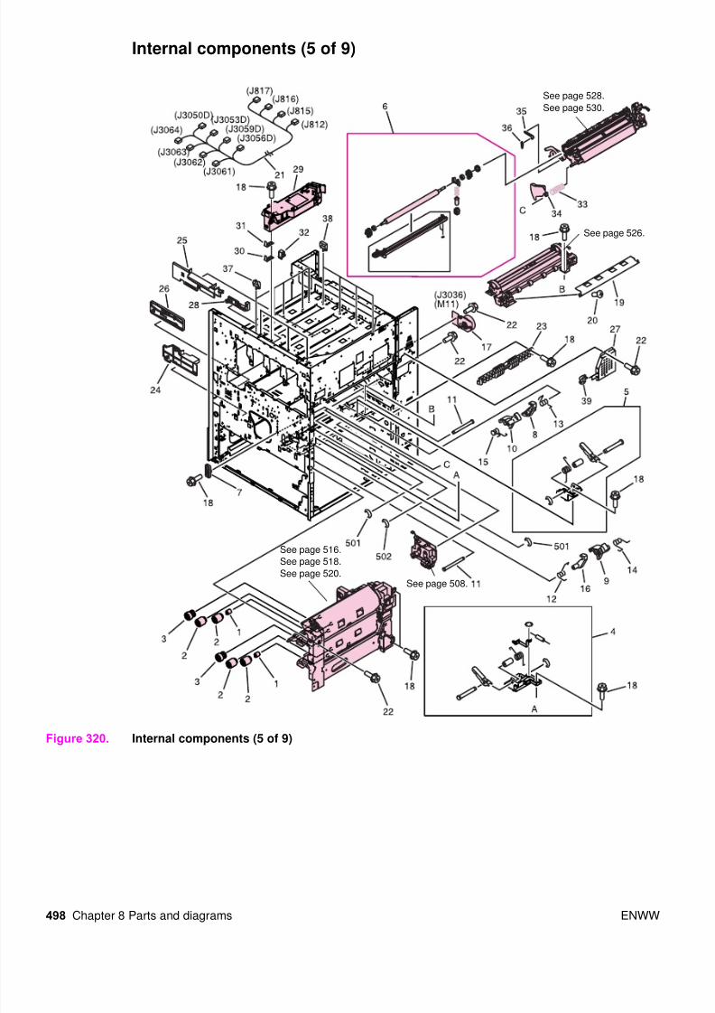
Internal components (5 of 9)
Figure 320. Internal components (5 of 9)
See page 508.
See page 516.
See page 518.
See page 520.
See page 526.
See page 528.
See page 530.
8/18/2019 9500 Parts Catalog
http://slidepdf.com/reader/full/9500-parts-catalog 27/84
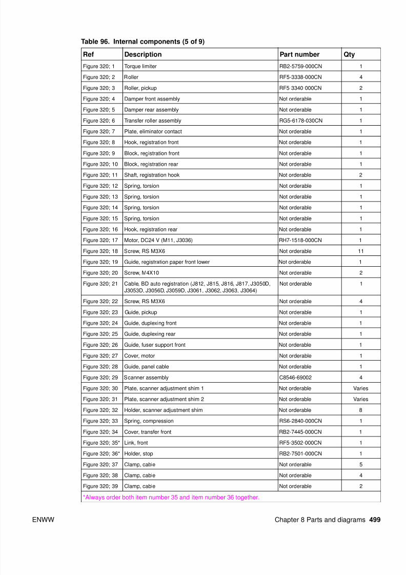
ENWW Chapter 8 Parts and diagrams 499
Table 96. Internal components (5 of 9)
Ref Description Part number Qty
Figure 320; 1 Torque limiter RB2-5759-000CN 1
Figure 320; 2 Roller RF5-3338-000CN 4
Figure 320; 3 Roller, pickup RF5-3340-000CN 2
Figure 320; 4 Damper front assembly Not orderable 1
Figure 320; 5 Damper rear assembly Not orderable 1
Figure 320; 6 Transfer roller assembly RG5-6178-030CN 1
Figure 320; 7 Plate, eliminator contact Not orderable 1
Figure 320; 8 Hook, registration front Not orderable 1
Figure 320; 9 Block, registration front Not orderable 1
Figure 320; 10 Block, registration rear Not orderable 1
Figure 320; 11 Shaft, registration hook Not orderable 2
Figure 320; 12 Spring, torsion Not orderable 1
Figure 320; 13 Spring, torsion Not orderable 1
Figure 320; 14 Spring, torsion Not orderable 1
Figure 320; 15 Spring, torsion Not orderable 1
Figure 320; 16 Hook, registration rear Not orderable 1
Figure 320; 17 Motor, DC24 V (M11, J3036) RH7-1518-000CN 1
Figure 320; 18 Screw, RS M3X6 Not orderable 11
Figure 320; 19 Guide, registration paper front lower Not orderable 1
Figure 320; 20 Screw, M4X10 Not orderable 2
Figure 320; 21 Cable, BD auto registration (J812, J815, J816, J817, J3050D,
J3053D, J3056D, J3059D, J3061, J3062, J3063, J3064)
Not orderable 1
Figure 320; 22 Screw, RS M3X6 Not orderable 4
Figure 320; 23 Guide, pickup Not orderable 1
Figure 320; 24 Guide, duplexing front Not orderable 1
Figure 320; 25 Guide, duplexing rear Not orderable 1
Figure 320; 26 Guide, fuser support front Not orderable 1
Figure 320; 27 Cover, motor Not orderable 1
Figure 320; 28 Guide, panel cable Not orderable 1
Figure 320; 29 Scanner assembly C8546-69002 4
Figure 320; 30 Plate, scanner adjustment shim 1 Not orderable Varies
Figure 320; 31 Plate, scanner adjustment shim 2 Not orderable Varies
Figure 320; 32 Holder, scanner adjustment shim Not orderable 8
Figure 320; 33 Spring, compression RS6-2840-000CN 1
Figure 320; 34 Cover, transfer front RB2-7445-000CN 1
Figure 320; 35* Link, front RF5-3502-000CN 1
Figure 320; 36* Holder, stop RB2-7501-000CN 1
Figure 320; 37 Clamp, cable Not orderable 5
Figure 320; 38 Clamp, cable Not orderable 4
Figure 320; 39 Clamp, cable Not orderable 2
*Always order both item number 35 and item number 36 together.
8/18/2019 9500 Parts Catalog
http://slidepdf.com/reader/full/9500-parts-catalog 28/84
500 Chapter 8 Parts and diagrams ENWW
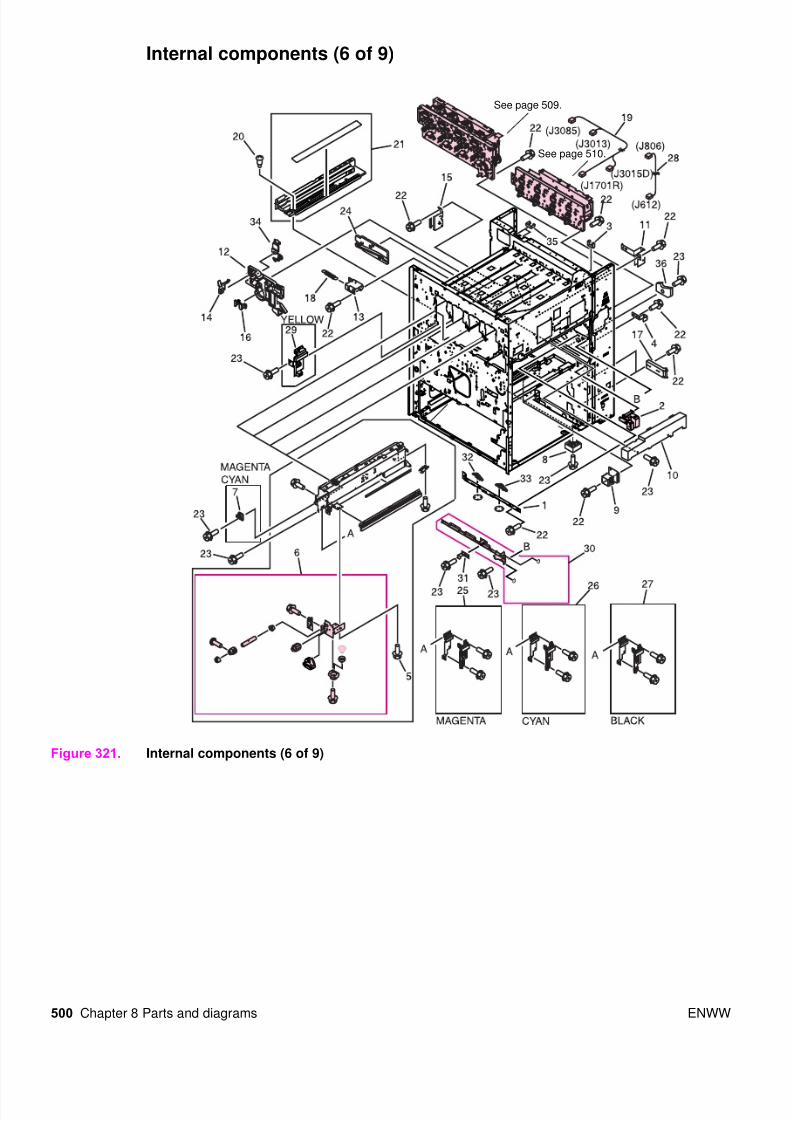
Internal components (6 of 9)
Figure 321. Internal components (6 of 9)
See page 509.
See page 510.

8/18/2019 9500 Parts Catalog
http://slidepdf.com/reader/full/9500-parts-catalog 29/84
ENWW Chapter 8 Parts and diagrams 501
Table 97. Internal components (6 of 9)
Ref Description Part number Qty
Figure 321; 1 Plate, rail support Not orderable 1
Figure 321; 2 Block, damper RB2-7217-000CN 1
Figure 321; 3 Clip, cable Not orderable 1
Figure 321; 4 Fuser plate, high-voltage Not orderable 1
Figure 321; 5 Screw, RS M3X6 Not orderable 2
Figure 321; 6 Cartridge, click support assembly RG5-6141-020CN 1
Figure 321; 7 Support, claw (magenta, cyan) Not orderable 2
Figure 321; 8 Block, right Not orderable 1
Figure 321; 9 Cover, latch Not orderable 2
Figure 321; 10 Duct, fan Not orderable 1
Figure 321; 11 Rail, guide rear Not orderable 1
Figure 321; 12 Support, cleaner rear Not orderable 1
Figure 321; 13 Plate, mount Not orderable 1
Figure 321; 14 Plate, contact Not orderable 1
Figure 321; 15 Support, cleaner rear support Not orderable 1
Figure 321; 16 Holder, positioning Not orderable 1
Figure 321; 17 Hinge, right cover Not orderable 2
Figure 321; 18 Spring, tension Not orderable 1
Figure 321; 19 Right upper crossmember cable (J1701R, J3015D, J3013, J3085)
(HP CLJ 9500 only)
RG5-5943-000CN 1
Figure 321; 19 Right upper crossmember cable (HP CLJ 9500mfp only) RG5-5974-000CN 1
Figure 321; 20 Screw, stepped M3 Not orderable 3
Figure 321; 21 Intermediate transfer belt (ITB) duct unit Not orderable 1
Figure 321; 22 Screw, RS M3X6 Not orderable 10
Figure 321; 23 Screw, RS M3X8 Not orderable 10
Figure 321; 24 Guide, fuser support Not orderable 1
Figure 321; 25 Magenta cartridge rail assembly Not orderable 1
Figure 321; 26 Cyan cartridge rail assembly Not orderable 1
Figure 321; 27 Black cartridge rail assembly Not orderable 1
Figure 321; 28 Toner cartridge cable (J612, J806) RG5-5939-000CN 1
Figure 321; 29 Rail, cartridge (yellow) Not orderable 1
Figure 321; 30 Rail, guide rear RF5-3546-020CN 1
Figure 321; 31 Plate, grounding RB2-7281-000CN 1
Figure 321; 32 Cam, right Not orderable 1
Figure 321; 33 Cam, left Not orderable 1
Figure 321; 34 Retainer, cleaner rear Not orderable 1
Figure 321; 35 Holder, edge Not orderable 2
Figure 321; 36 Block, support Not orderable 1

8/18/2019 9500 Parts Catalog
http://slidepdf.com/reader/full/9500-parts-catalog 30/84
502 Chapter 8 Parts and diagrams ENWW
Internal components (7 of 9)
Figure 322. Internal components (7 of 9)

8/18/2019 9500 Parts Catalog
http://slidepdf.com/reader/full/9500-parts-catalog 31/84
ENWW Chapter 8 Parts and diagrams 503
Table 98. Internal components (7 of 9)
Ref Description Part number Qty
Figure 322; 1 Screw, RS M3X6 Not orderable 10
Figure 322; 2 Angle adjustment plate assembly Not orderable 4
Figure 322; 3 Paper delivery sensor assembly (SR 2, J3016, J3017) RG5-6152-000CN 1
Figure 322; 4 Left interlock assembly RG5-6037-000CN 1
Figure 322; 5 Holder, ozone Not orderable 1
Figure 322; 6 Duct, ozone Not orderable 1
Figure 322; 7 Clip, cable Not orderable 1
Figure 322; 8 Screw, RS M3X6 Not orderable 3
Figure 322; 9 Cable, laser assembly (J108, J109, J110, J111, J3009, J3010, J3011,
J3012)
RG5-6148-000CN 1
Figure 322; 10 M-purpose support assembly rear RG5-6107-000CN 1
Figure 322; 11 Slide arm assembly RG5-6130-000CN 1
Figure 322; 12 Humidity sensor assembly RG5-6153-000CN 1
Figure 322; 13 Right interlock assembly RG5-6036-000CN 1
Figure 322; 14 Fan (FM3, J3078) RH7-1554-000CN 1
Figure 322; 15 Holder, fan Not orderable 1
Figure 322; 16 Fan (FM7, J3089) RH7-1564-000CN 1
Figure 322; 17 Cover, fan Not orderable 1
Figure 322; 18 Clamp, cord Not orderable 1
Figure 322; 19 Clamp, cable Not orderable 8
Figure 322; 20 Clip, cable Not orderable 1
Figure 322; 21 Cover, sensor Not orderable 1
8/18/2019 9500 Parts Catalog
http://slidepdf.com/reader/full/9500-parts-catalog 32/84
504 Chapter 8 Parts and diagrams ENWW
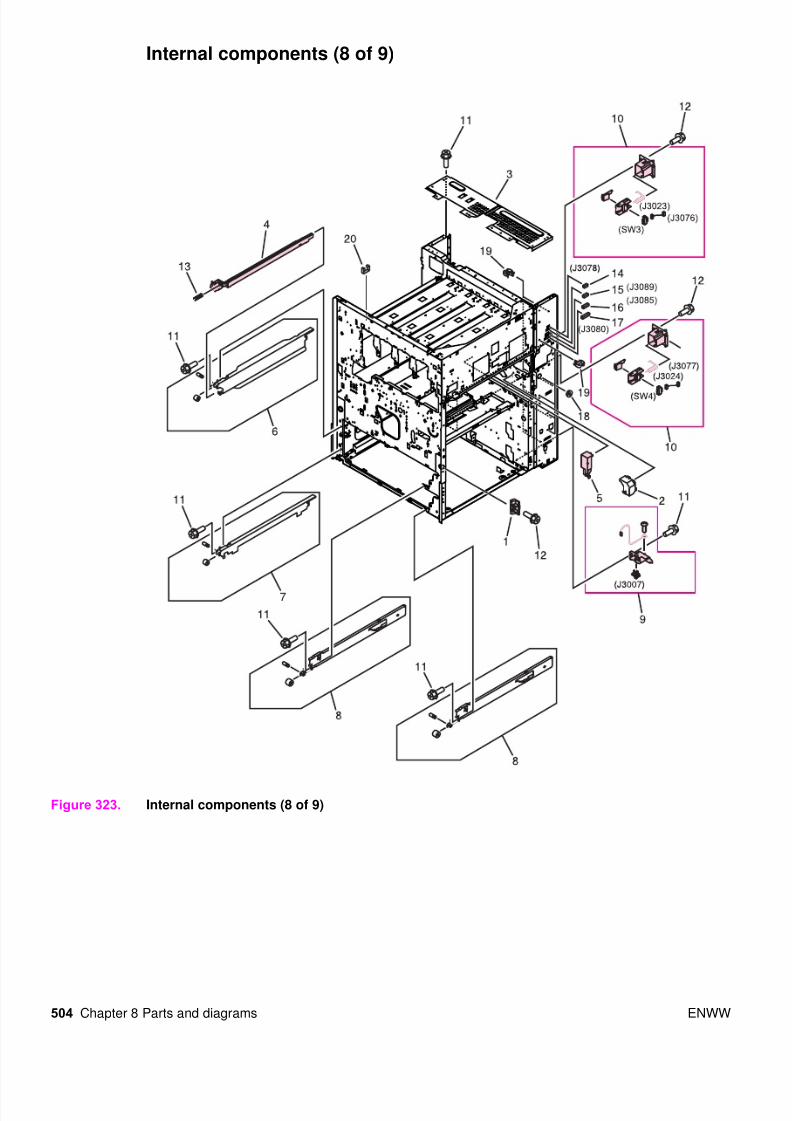
Internal components (8 of 9)
Figure 323. Internal components (8 of 9)

8/18/2019 9500 Parts Catalog
http://slidepdf.com/reader/full/9500-parts-catalog 33/84
ENWW Chapter 8 Parts and diagrams 505
Table 99. Internal components (8 of 9)
Ref Description Part number Qty
Figure 323; 1 Support, right door stop Not orderable 1
Figure 323; 2 Cover, registration Not orderable 1
Figure 323; 3 Crossmember, rear Not orderable 1
Figure 323; 4 Rod, switch RB2-7354-000CN 1
Figure 323; 5 Cover, transfer cable RB2-7444-000CN 1
Figure 323; 6 Left rail upper assembly Not orderable 1
Figure 323; 7 Left rail lower assembly Not orderable 1
Figure 323; 8 Right rail assembly Not orderable 2
Figure 323; 9 Connector assembly (J3007) RG5-5779-000CN 1
Figure 323; 10 End paper sensor assembly (J3023, J3076, J3024, J3077, SW3, J3023,
SW4, J3024)
RG5-5699-000CN 2
Figure 323; 11 Screw, RS M3X6 Not orderable 6
Figure 323; 12 Screw, RS M3X8 Not orderable 4
Figure 323; 13 Spring, compression Not orderable 1
Figure 323; 14 Connector, 3P (J3078) VS1-5057-003CN 1
Figure 323; 15 Connector, 5P (J3089) VS1-5057-005CN 1
Figure 323; 16 Connector, 10P (J3085) VS1-5057-010CN 1
Figure 323; 17 Connector, 20P (J3080) VS1-5057-020CN 1
Figure 323; 18 Bushing Not orderable 1
Figure 323; 19 Clip, cable Not orderable 8
Figure 323; 20 Clip, cable Not orderable 1

8/18/2019 9500 Parts Catalog
http://slidepdf.com/reader/full/9500-parts-catalog 34/84
506 Chapter 8 Parts and diagrams ENWW
Internal components (9 of 9)
Figure 324. Internal components (9 of 9)

8/18/2019 9500 Parts Catalog
http://slidepdf.com/reader/full/9500-parts-catalog 35/84
ENWW Chapter 8 Parts and diagrams 507
Table 100. Internal components (9 of 9)
Ref Description Part number Qty
Figure 324; 1 High-voltage PCB assembly RG5-6031-000CN 1
Figure 324; 2 High-voltage connector PCB assembly (J206) RG5-6032-000CN 1
Figure 324; 3 Shield case assembly Not orderable 1
Figure 324; 4 Holder, upper fan Not orderable 1
Figure 324; 5 Holder, lower fan Not orderable 1
Figure 324; 6 Guide, main cable Not orderable 1
Figure 324; 7 Power supply assembly 110-127 V (FM5, 100-127 V)
Power supply assembly 220-240 V (FM5, 220-240 V)
RH3-2236-030CN new
C8546-69003 exchange
RH3-2237-040CN new
C8546-69004 exchange
1
1
Figure 324; 8 Power supply mount assembly Not orderable 1
Figure 324; 9 Screw, RS M3X6 Not orderable 6
Figure 324; 10 Screw, RS M3X8 Not orderable 10
Figure 324; 11 DC controller PCB assembly RG5-5901-060CN new
C8546-69005 exchange
1
Figure 324; 12 High-voltage holder assembly RG5-6129-000CN 1
Figure 324; 13 Cable, rear lower (J3, J4, J5, J9, J70, J102, J113, J117, J118, J119, J120,
J124, J125, J129, J130, J810, J824, J3000D, J3000DH, J3001D,
J3001DH, J3002D, J3002DH, J3007DAJ3007DB, J3036,J3037DB, J9501,
J9502, J9503, J9504))
RG5-5919-000CN 1
Figure 324; 14 Cable, process cartridge (J202, J608) RG5-5938-000CN 1
Figure 324; 15 Cable, high-voltage control (J101, J203) RG5-5940-000CN 1
Figure 324; 16 Cable, fuser motor (J116, J3035) RG5-5952-000CN 1
Figure 324; 17 Cable, formatter (J2, J9002) RG5-5933-000CN 1
Figure 324; 18 Cable, high-voltage (J1, J201) RG5-5937-000CN 1Figure 324; 19 Cable, rear upper (J112, J123, J803, J811, J821, J901, J3008, J3016D,
J3018D, J3069D, J3086D) (HP CLJ 9500 only)
RG5-5920-000CN 1
Figure 324; 19 Cable, rear upper (HP CLJ 9500mfp only) RG5-5990-000CN 1
Figure 324; 20 Fan (FM2, J818) RH7-1521-000CN 1
Figure 324; 21 Fan (FM4, J819) RH7-1522-000CN 1
Figure 324; 22 Cable, rear holder assembly (J122, J3076, J3077D) RG5-6159-000CN 1
Figure 324; 23 Cable, flat (J103, J9002) RH2-5509-000CN 1
Figure 324; 24 Cable, flat (J104, J106< J601, J616, J801) RH2-5507-000CN 1
Figure 324; 25 High-voltage power supply PCB unit RH3-0353-020CN 1
Figure 324; 26 Plate, test switch Not orderable 1
Figure 324; 27 Cable, post controller (J210, J501) RG5-5966-000CN 1
Figure 324; 28 Regulator PCB assembly RG5-5971-000CN 1
Figure 324; 29 Cable, rear lower (J121, J3025D, J3027D), J3022D, J3026D) RG5-5975-000CN 1

8/18/2019 9500 Parts Catalog
http://slidepdf.com/reader/full/9500-parts-catalog 36/84
508 Chapter 8 Parts and diagrams ENWW
Registration drive assembly
Figure 325. Registration drive assembly
Note Callout numbers that are followed by a “T” indicate the number of teeth on the specified gear. For
example, 21T is a gear with 21 teeth.
Table 101. Registration drive assembly
Ref Description Part number Qty
Figure 325; all Registration drive assembly RG5-6015-000CN 1
Figure 325; 1 Pin holder unit (registration drive assembly; J3022) RG5-6160-000CN 1

8/18/2019 9500 Parts Catalog
http://slidepdf.com/reader/full/9500-parts-catalog 37/84
ENWW Chapter 8 Parts and diagrams 509
Process cartridge drive assembly (image drum drive)
Figure 326. Process cartridge drive assembly (image drum drive)
Table 102. Process cartridge drive assembly (image drum drive)
Ref Description Part number Qty
Figure 326; all Process cartridge drive assembly (J613, J614, J615, M8, J609, J12, J13,
J14, J15, J1002, J1003, J1004, J1005, M7, J610, M9, J611, M2, J604,
J606, M1, M3, M5, J603, J605, J607)
RG5-6188-030CN new
C8546-69006 exchange
1
Figure 326; 1 Antenna holder assembly RG5-6026-000CN 4
Figure 326; 2 Process cartridge (image drum) PCB assembly RG5-5905-000CN 1

8/18/2019 9500 Parts Catalog
http://slidepdf.com/reader/full/9500-parts-catalog 38/84
510 Chapter 8 Parts and diagrams ENWW
Toner cartridge drive assembly (print cartridge drive)
Figure 327. Toner cartridge drive assembly (print cartridge drive)
Note Callout numbers that are followed by a “T” indicate the number of teeth on the specified gear. Forexample, 21T is a gear with 21 teeth.
8/18/2019 9500 Parts Catalog
http://slidepdf.com/reader/full/9500-parts-catalog 39/84
ENWW Chapter 8 Parts and diagrams 511
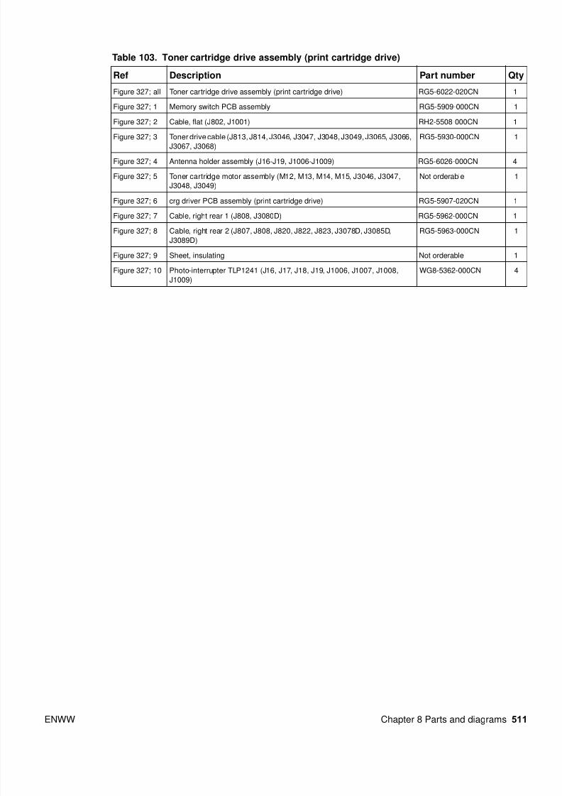
Table 103. Toner cartridge drive assembly (print cartridge drive)
Ref Description Part number Qty
Figure 327; all Toner cartridge drive assembly (print cartridge drive) RG5-6022-020CN 1
Figure 327; 1 Memory switch PCB assembly RG5-5909-000CN 1
Figure 327; 2 Cable, flat (J802, J1001) RH2-5508-000CN 1
Figure 327; 3 Toner drive cable (J813, J814, J3046, J3047, J3048, J3049, J3065, J3066,J3067, J3068)
RG5-5930-000CN 1
Figure 327; 4 Antenna holder assembly (J16-J19, J1006-J1009) RG5-6026-000CN 4
Figure 327; 5 Toner cartridge motor assembly (M12, M13, M14, M15, J3046, J3047,
J3048, J3049)
Not orderable 1
Figure 327; 6 crg driver PCB assembly (print cartridge drive) RG5-5907-020CN 1
Figure 327; 7 Cable, right rear 1 (J808, J3080D) RG5-5962-000CN 1
Figure 327; 8 Cable, right rear 2 (J807, J808, J820, J822, J823, J3078D, J3085D,
J3089D)
RG5-5963-000CN 1
Figure 327; 9 Sheet, insulating Not orderable 1
Figure 327; 10 Photo-interrupter TLP1241 (J16, J17, J18, J19, J1006, J1007, J1008,
J1009)
WG8-5362-000CN 4

8/18/2019 9500 Parts Catalog
http://slidepdf.com/reader/full/9500-parts-catalog 40/84
512 Chapter 8 Parts and diagrams ENWW
Fuser drive assembly
Figure 328. Fuser drive assembly
Note Callout numbers that are followed by a “T” indicate the number of teeth on the specified gear. Forexample, 21T is a gear with 21 teeth.

8/18/2019 9500 Parts Catalog
http://slidepdf.com/reader/full/9500-parts-catalog 41/84
ENWW Chapter 8 Parts and diagrams 513
Table 104. Fuser drive assembly
Ref Description Part number Qty
Figure 328; all Fuser drive assembly RG5-6018-000CN 1
Figure 328; 1 Motor, DC24 V (M10, J3035) RH7-1519-000CN 1
Figure 328; 2 Coupler Not orderable 1
Figure 328; 3 Spring, compression Not orderable 1

8/18/2019 9500 Parts Catalog
http://slidepdf.com/reader/full/9500-parts-catalog 42/84
514 Chapter 8 Parts and diagrams ENWW
Cassette assembly
Figure 329. Cassette assembly
Note Callout numbers that are followed by a “T” indicate the number of teeth on the specified gear. Forexample, 21T is a gear with 21 teeth.
8/18/2019 9500 Parts Catalog
http://slidepdf.com/reader/full/9500-parts-catalog 43/84
ENWW Chapter 8 Parts and diagrams 515
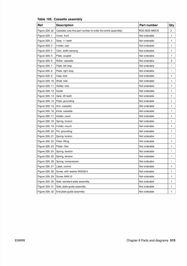
Table 105. Cassette assembly
Ref Description Part number Qty
Figure 329; all Cassette (use this part number to order the entire assembly) RG5-5635-080CN 2
Figure 329; 1 Cover, front Not orderable 1
Figure 329; 2 Gear, 11 teeth Not orderable 1
Figure 329; 3 Holder, rear Not orderable 1
Figure 329; 4 Cam, width sensing Not orderable 1
Figure 329; 5 Plate, coupler Not orderable 1
Figure 329; 6 Roller, cassette Not orderable 2
Figure 329; 7 Plate, left stop Not orderable 1
Figure 329; 8 Plate, right stop Not orderable 1
Figure 329; 9 Claw, lock Not orderable 1
Figure 329; 10 Shaft, lock Not orderable 1
Figure 329; 11 Holder, lock Not orderable 1
Figure 329; 12 Guide Not orderable 1
Figure 329; 13 Gear, 20 teeth Not orderable 1
Figure 329; 14 Plate, grounding Not orderable 1
Figure 329; 15 Arm, cassette Not orderable 1
Figure 329; 16 Knob, cassette Not orderable 1
Figure 329; 17 Holder, cover Not orderable 1
Figure 329; 18 Spring, torsion Not orderable 1
Figure 329; 19 Holder, mount Not orderable 1
Figure 329; 20 Pin, grounding Not orderable 1
Figure 329; 21 Spring, torsion Not orderable 1
Figure 329; 22 Plate, lifting Not orderable 1
Figure 329; 23 Plater, lifter Not orderable 1
Figure 329; 24 Spring, tension Not orderable 1
Figure 329; 25 Spring, tension Not orderable 1
Figure 329; 26 Spring, compression Not orderable 1
Figure 329; 27 Label, control Not orderable 1
Figure 329; 28 Screw, with washer M3X29.5 Not orderable 1
Figure 329; 29 Screw, M4X10 Not orderable 1
Figure 329; 30 Side, standard plate assembly Not orderable 1
Figure 329; 31 Side, plate guide assembly Not orderable 1
Figure 329; 32 End plate guide assembly Not orderable 1

8/18/2019 9500 Parts Catalog
http://slidepdf.com/reader/full/9500-parts-catalog 44/84
516 Chapter 8 Parts and diagrams ENWW
Paper pickup assembly (1 of 3)
Figure 330. Paper pickup assembly (1 of 3)
Note Callout numbers that are followed by a “T” indicate the number of teeth on the specified gear. Forexample, 21T is a gear with 21 teeth.

8/18/2019 9500 Parts Catalog
http://slidepdf.com/reader/full/9500-parts-catalog 45/84
ENWW Chapter 8 Parts and diagrams 517
Table 106. Paper pickup assembly (1 of 3)
Ref Description Part number Qty
Figure 330; all
Figure 331; all
Figure 332; all
Paper pickup assembly (use this part number to order the entire assembly) RG5-6196-000CN 1
Figure 330; 2 Motor, pickup assembly (M23, J11) Not orderable 1
Figure 330; 3 Screw, M4X10 Not orderable 5
Figure 330; 4 Screw, RS M3X6 Not orderable 5
Figure 330; 24 Screw, RS M3X8 Not orderable 12
Figure 330; 27 Lever, release Not orderable 2
Figure 330; 28 Flag, right cover assembly Not orderable 2
Figure 330; 29 Arm, lock Not orderable 2
Figure 330; 30 Spring, torsion Not orderable 1
Figure 330; 31 Spring, compression Not orderable 2
Figure 330; 32 Spring, tension Not orderable 2
Figure 330; 32 Screw, RS M3X8 Not orderable 5
Figure 330; 34 Holder, gear Not orderable 1
Figure 330; 36 Rod, pickup Not orderable 1
Figure 330; 37 Motor, DC24 V (M24, J12) (M25, J13) Not orderable 2
Figure 330; 46 Spring, tension Not orderable 1
Figure 330; 47 Screw, with washer RS M3X6 Not orderable 4
Figure 330; 48 Ring, E Not orderable 1
Figure 330; 49 Paper width sensor unit (SW5, J52, SW6, J54) Not orderable 1
Figure 330; 50 Flag, sensor Not orderable 2
Figure 330; 51 Holder, gear Not orderable 1
Figure 330; 52 Spring, torsion Not orderable 2
Figure 330; 115 Connector, 4P (J11) Not orderable 1

8/18/2019 9500 Parts Catalog
http://slidepdf.com/reader/full/9500-parts-catalog 46/84
518 Chapter 8 Parts and diagrams ENWW
Paper pickup assembly (2 of 3)
Figure 331. Paper pickup assembly (2 of 3)
Note Callout numbers that are followed by a “T” indicate the number of teeth on the specified gear. Forexample, 21T is a gear with 21 teeth.

8/18/2019 9500 Parts Catalog
http://slidepdf.com/reader/full/9500-parts-catalog 47/84
ENWW Chapter 8 Parts and diagrams 519
Table 107. Paper pickup assembly (2 of 3)
Ref Description Part number Qty
Figure 331; 1 Screw, RS M3X6 Not orderable 5
Figure 331; 6 Guide, pickup out Not orderable 1
Figure 331; 7 Plate, right support Not orderable 2
Figure 331; 8 Crossmember, pickup Not orderable 1
Figure 331; 20 Spring, tension Not orderable 2
Figure 331; 21 Spring, tension Not orderable 2
Figure 331; 22 Screw, M4X10 Not orderable 5
Figure 331; 23 Screw, RS M3X6 Not orderable 13
Figure 331; 24 Screw, RS M3X8 Not orderable 12
Figure 331; 80 Guide, right Not orderable 2
Figure 331; 81 Guide, feed out Not orderable 2
Figure 331; 82 Roller, feed Not orderable 4
Figure 331; 83 Shaft, feed roller Not orderable 2
Figure 331; 84 Holder, feed roller Not orderable 2
Figure 331; 85 Screw, RS M3X6 Not orderable 4
Figure 331; 86 Ring, E Not orderable 4
Figure 331; 87 Holder, retard Not orderable 2
Figure 331; 88 Plate, holder support Not orderable 2
Figure 331; 89 Shaft, retard Not orderable 2
Figure 331; 90 Bushing Not orderable 2
Figure 331; 92 Screw, M4X10 Not orderable 2
Figure 331; 93 Pin, dowel Not orderable 2
Figure 331; 94 Ring, E Not orderable 2
Figure 331; 107 Feed PCB assembly Not orderable 1
Figure 331; 108 Cable, pickup Not orderable 1
Figure 331; 109 Plate, front m-purpose support Not orderable 1
Figure 331; 112 Ring, E Not orderable 2

8/18/2019 9500 Parts Catalog
http://slidepdf.com/reader/full/9500-parts-catalog 48/84
520 Chapter 8 Parts and diagrams ENWW
Paper pickup assembly (3 of 3)
Figure 332. Paper pickup assembly (3 of 3)
Note Callout numbers that are followed by a “T” indicate the number of teeth on the specified gear. Forexample, 21T is a gear with 21 teeth.

8/18/2019 9500 Parts Catalog
http://slidepdf.com/reader/full/9500-parts-catalog 49/84
ENWW Chapter 8 Parts and diagrams 521
Table 108. Paper pickup assembly (3 of 3)
Ref Description Part number Qty
Figure 332; 5 Roller, vertical path Not orderable 2
Figure 332; 9 Guide, front inlet Not orderable 2
Figure 332; 10 Timing belt Not orderable 1
Figure 332; 11 Vertical path drive gear unit Not orderable 1
Figure 332; 12 Vertical Path pulley unit Not orderable 1
Figure 332; 13 Bushing Not orderable 2
Figure 332; 14 Bushing Not orderable 2
Figure 332; 15 Bushing Not orderable 2
Figure 332; 19 Spring, tension Not orderable 3
Figure 332; 23 Screw, RS M3X6 Not orderable 13
Figure 332; 24 Screw, RS M3X8 Not orderable 12
Figure 332; 25 Ring, E Not orderable 5
Figure 332; 26 Ring, E Not orderable 4
Figure 332; 56 Roller, feed Not orderable 1
Figure 332; 57 Guide, pickup feed Not orderable 1
Figure 332; 58 Holder, feed sensor Not orderable 1
Figure 332; 59 Flag, feed sensor Not orderable 2
Figure 332; 60 Spring, torsion Not orderable 2
Figure 332; 61 Bushing Not orderable 1
Figure 332; 62 Bushing Not orderable 1
Figure 332; 65 Screw, M4X10 Not orderable 2
Figure 332; 66 Pin, dowel Not orderable 1
Figure 332; 67 Ring, E Not orderable 2
Figure 332; 68 Roller, feed Not orderable 1
Figure 332; 69 Guide, feed roller Not orderable 1
Figure 332; 70 Holder, feed sensor Not orderable 1
Figure 332; 71 Flag, feed sensor Not orderable 2
Figure 332; 72 Spring, torsion Not orderable 2
Figure 332; 73 Bushing Not orderable 1
Figure 332; 74 Bushing Not orderable 1
Figure 332; 77 Screw, M4X10 Not orderable 2
Figure 332; 78 Pin, dowel Not orderable 1
Figure 332; 79 Ring, E Not orderable 2
Figure 332; 95 Flag, paper sensor Not orderable 2
Figure 332; 96 Guide, inlet Not orderable 2
Figure 332; 97 Holder, pickup Not orderable 2
Figure 332; 98 Holder, pickup roller Not orderable 2
Figure 332; 99 Flag, paper height Not orderable 2
Figure 332; 100 Shaft, pickup Not orderable 2
Figure 332; 101 Shaft, feed Not orderable 2
Figure 332; 102 Bushing Not orderable 4
Figure 332; 105 Ring, E Not orderable 2
Figure 332; 106 Ring, E Not orderable 2

8/18/2019 9500 Parts Catalog
http://slidepdf.com/reader/full/9500-parts-catalog 50/84
522 Chapter 8 Parts and diagrams ENWW
Manual feed pickup assembly (tray 1) (1 of 2)
Figure 333. Manual feed pickup assembly (tray 1) (1 of 2)
Note Callout numbers that are followed by a “T” indicate the number of teeth on the specified gear. Forexample, 21T is a gear with 21 teeth.
8/18/2019 9500 Parts Catalog
http://slidepdf.com/reader/full/9500-parts-catalog 51/84
ENWW Chapter 8 Parts and diagrams 523
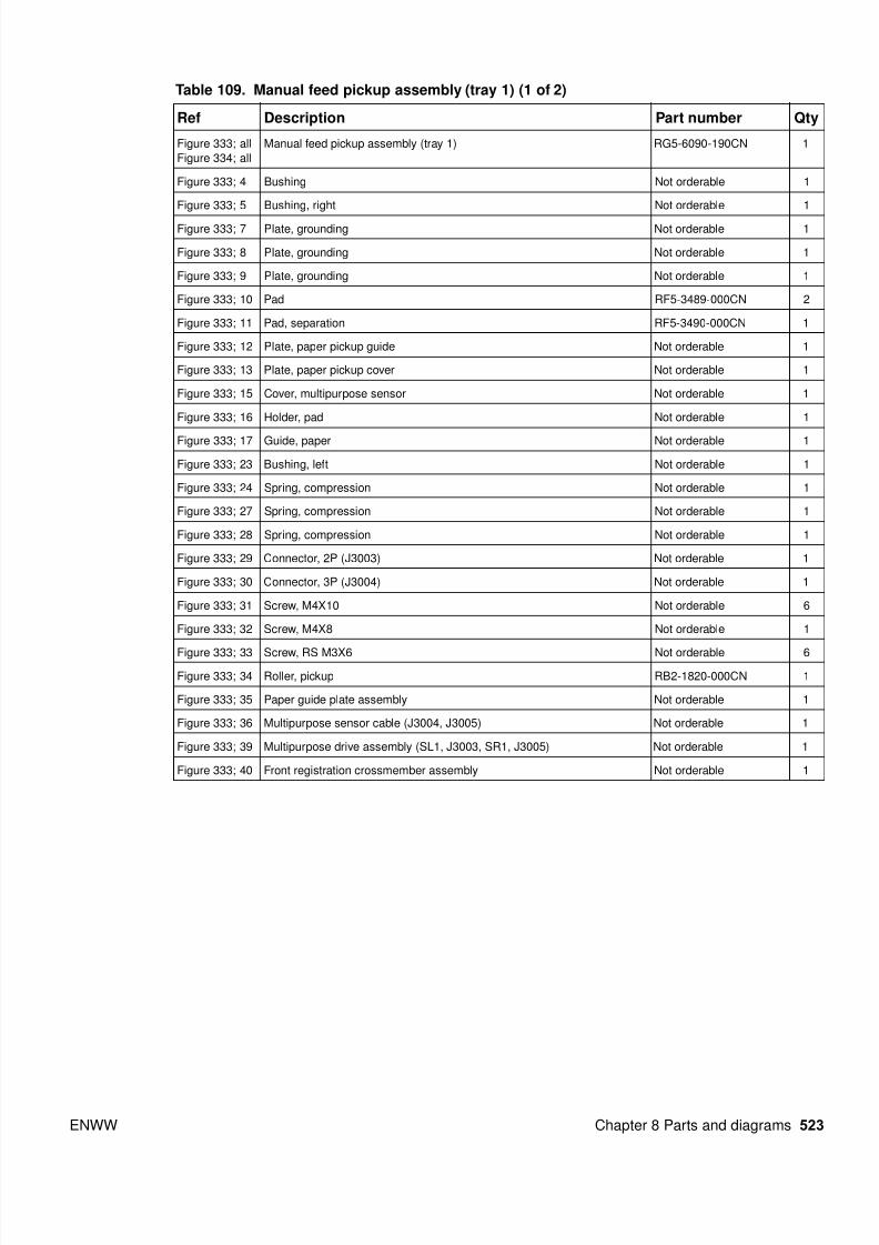
Table 109. Manual feed pickup assembly (tray 1) (1 of 2)
Ref Description Part number Qty
Figure 333; all
Figure 334; all
Manual feed pickup assembly (tray 1) RG5-6090-190CN 1
Figure 333; 4 Bushing Not orderable 1
Figure 333; 5 Bushing, right Not orderable 1
Figure 333; 7 Plate, grounding Not orderable 1
Figure 333; 8 Plate, grounding Not orderable 1
Figure 333; 9 Plate, grounding Not orderable 1
Figure 333; 10 Pad RF5-3489-000CN 2
Figure 333; 11 Pad, separation RF5-3490-000CN 1
Figure 333; 12 Plate, paper pickup guide Not orderable 1
Figure 333; 13 Plate, paper pickup cover Not orderable 1
Figure 333; 15 Cover, multipurpose sensor Not orderable 1
Figure 333; 16 Holder, pad Not orderable 1
Figure 333; 17 Guide, paper Not orderable 1
Figure 333; 23 Bushing, left Not orderable 1
Figure 333; 24 Spring, compression Not orderable 1
Figure 333; 27 Spring, compression Not orderable 1
Figure 333; 28 Spring, compression Not orderable 1
Figure 333; 29 Connector, 2P (J3003) Not orderable 1
Figure 333; 30 Connector, 3P (J3004) Not orderable 1
Figure 333; 31 Screw, M4X10 Not orderable 6
Figure 333; 32 Screw, M4X8 Not orderable 1
Figure 333; 33 Screw, RS M3X6 Not orderable 6
Figure 333; 34 Roller, pickup RB2-1820-000CN 1
Figure 333; 35 Paper guide plate assembly Not orderable 1
Figure 333; 36 Multipurpose sensor cable (J3004, J3005) Not orderable 1
Figure 333; 39 Multipurpose drive assembly (SL1, J3003, SR1, J3005) Not orderable 1
Figure 333; 40 Front registration crossmember assembly Not orderable 1

8/18/2019 9500 Parts Catalog
http://slidepdf.com/reader/full/9500-parts-catalog 52/84
524 Chapter 8 Parts and diagrams ENWW
Manual feed pickup assembly (tray 1) (2 of 2)
Figure 334. Manual feed pickup assembly (tray 1) (2 of 2)
Note Callout numbers that are followed by a “T” indicate the number of teeth on the specified gear. Forexample, 21T is a gear with 21 teeth.

8/18/2019 9500 Parts Catalog
http://slidepdf.com/reader/full/9500-parts-catalog 53/84
ENWW Chapter 8 Parts and diagrams 525
Table 110. Manual feed pickup assembly (tray 1) (2 of 2)
Ref Description Part number Qty
Figure 334; 2 Arm, sensor Not orderable 1
Figure 334; 3 Spring, torsion Not orderable 1
Figure 334; 6 Knob Not orderable 1
Figure 334; 18 Lever, sensor Not orderable 1
Figure 334; 19 Frame, paper sensor Not orderable 1
Figure 334; 20 Spring, torsion Not orderable 1
Figure 334; 21 Flag, sensor Not orderable 1
Figure 334; 22 Mount, shaft Not orderable 1
Figure 334; 37 Multipurpose tray assembly (SR43, J3084) Not orderable 1
Figure 334; 38 Multipurpose, cover assembly (J3002, J3003, J3004, J3006, J3084) Not orderable
8/18/2019 9500 Parts Catalog
http://slidepdf.com/reader/full/9500-parts-catalog 54/84

8/18/2019 9500 Parts Catalog
http://slidepdf.com/reader/full/9500-parts-catalog 55/84
ENWW Chapter 8 Parts and diagrams 527
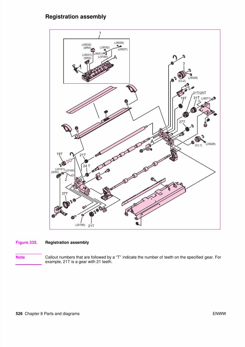
Table 111. Registration assembly
Ref Description Part number Qty
Figure 335; all Registration assembly (use this part number to order the entire assembly;
SR5)
RG5-6016-000CN 1
Figure 335; 1 Registration sensor holder assembly (SR4, J3032, SR3, J3031, J3027,
J3029, J3031, J3032, J3100)
Not orderable 1
Figure 335; 2 Cable, sensor (J3100, J3101) Not orderable 1
Figure 335; 3 Clutch, electrical mechanical (CL, J3029) Not orderable 1
Figure 335; 4 Clutch, electrical mechanical (CL1, J3028) Not orderable 1
8/18/2019 9500 Parts Catalog
http://slidepdf.com/reader/full/9500-parts-catalog 56/84
528 Chapter 8 Parts and diagrams ENWW
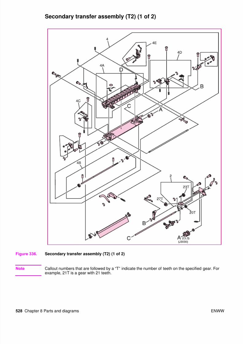
Secondary transfer assembly (T2) (1 of 2)
Figure 336. Secondary transfer assembly (T2) (1 of 2)
Note Callout numbers that are followed by a “T” indicate the number of teeth on the specified gear. Forexample, 21T is a gear with 21 teeth.
8/18/2019 9500 Parts Catalog
http://slidepdf.com/reader/full/9500-parts-catalog 57/84
ENWW Chapter 8 Parts and diagrams 529
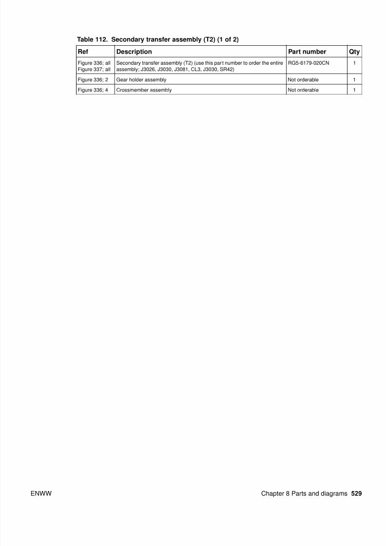
Table 112. Secondary transfer assembly (T2) (1 of 2)
Ref Description Part number Qty
Figure 336; all
Figure 337; all
Secondary transfer assembly (T2) (use this part number to order the entire
assembly; J3026, J3030, J3081, CL3, J3030, SR42)
RG5-6179-020CN 1
Figure 336; 2 Gear holder assembly Not orderable 1
Figure 336; 4 Crossmember assembly Not orderable 1

8/18/2019 9500 Parts Catalog
http://slidepdf.com/reader/full/9500-parts-catalog 58/84
530 Chapter 8 Parts and diagrams ENWW
Secondary transfer assembly (T2) (2 of 2)
Figure 337. Secondary transfer assembly (T2) (2 of 2)
Note Callout numbers that are followed by a “T” indicate the number of teeth on the specified gear. Forexample, 21T is a gear with 21 teeth.
Table 113. Secondary transfer assembly (T2) (2 of 2)
Ref Description Part number Qty
Figure 337; 1 Secondary transfer (T2) cable assembly (use this part number to order the
entire assembly)
RG5-6179-030CN 1
Figure 337; 3 Guide, holder assembly Not orderable 1
8/18/2019 9500 Parts Catalog
http://slidepdf.com/reader/full/9500-parts-catalog 59/84
ENWW Chapter 8 Parts and diagrams 531
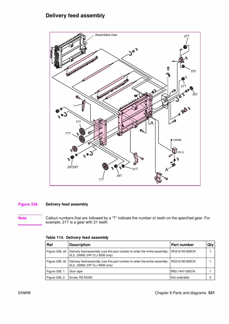
Delivery feed assembly
Figure 338. Delivery feed assembly
Note Callout numbers that are followed by a “T” indicate the number of teeth on the specified gear. Forexample, 21T is a gear with 21 teeth.
Assembled view
Table 114. Delivery feed assembly
Ref Description Part number Qty
Figure 338; all Delivery feed assembly (use this part number to order the entire assembly;
SL2, J3069) (HP CLJ 9500 only)
RG5-6150-000CN 1
Figure 338; all Delivery feed assembly (use this part number to order the entire assembly;
SL2, J3069) (HP CLJ 9500 only)
RG5-6190-000CN 1
Figure 338; 1 Door tape RB2-7447-000CN 1
Figure 338; 2 Screw, RS M3X6 Not orderable 2

8/18/2019 9500 Parts Catalog
http://slidepdf.com/reader/full/9500-parts-catalog 60/84
8/18/2019 9500 Parts Catalog
http://slidepdf.com/reader/full/9500-parts-catalog 61/84
ENWW Chapter 8 Parts and diagrams 533
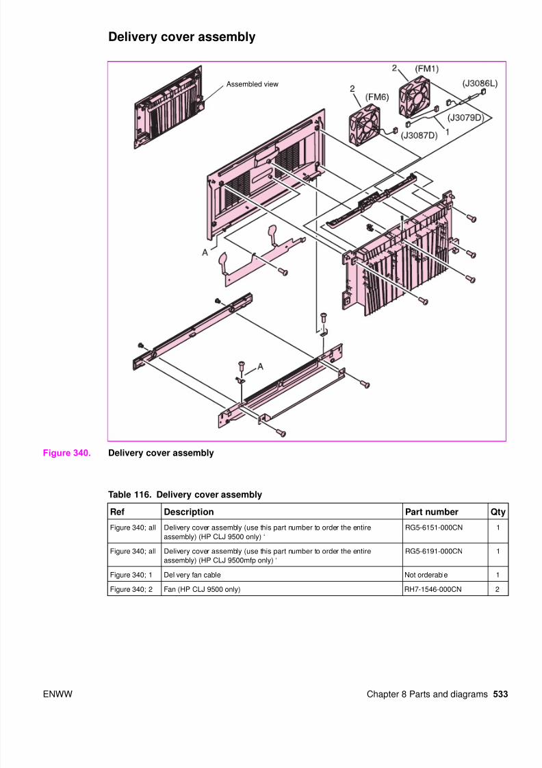
Delivery cover assembly
Figure 340. Delivery cover assembly
Assembled view
Table 116. Delivery cover assembly
Ref Description Part number Qty
Figure 340; all Delivery cover assembly (use this part number to order the entire
assembly) (HP CLJ 9500 only) ‘
RG5-6151-000CN 1
Figure 340; all Delivery cover assembly (use this part number to order the entire
assembly) (HP CLJ 9500mfp only) ‘
RG5-6191-000CN 1
Figure 340; 1 Delivery fan cable Not orderable 1
Figure 340; 2 Fan (HP CLJ 9500 only) RH7-1546-000CN 2
8/18/2019 9500 Parts Catalog
http://slidepdf.com/reader/full/9500-parts-catalog 62/84
534 Chapter 8 Parts and diagrams ENWW
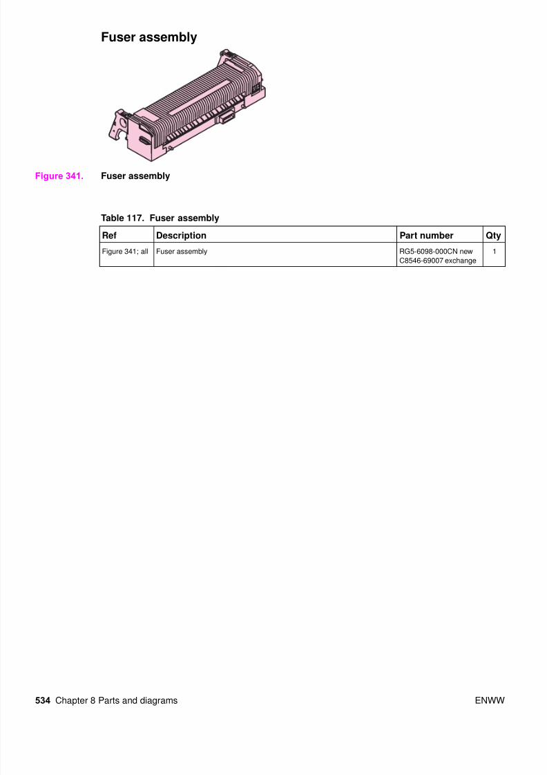
Fuser assembly
Figure 341. Fuser assembly
Table 117. Fuser assembly
Ref Description Part number Qty
Figure 341; all Fuser assembly RG5-6098-000CN new
C8546-69007 exchange
1

8/18/2019 9500 Parts Catalog
http://slidepdf.com/reader/full/9500-parts-catalog 63/84
ENWW Chapter 8 Parts and diagrams 535
PCB assemblies
Figure 342. PCB assemblies
Table 118. PCB assemblies
Ref Description Part number Qty
Figure 342; 1 DC controller PCB assembly RG5-5901-060CN 1
Figure 342; 2 Process cartridge (image drum) PCB assembly RG5-5905-000CN 1
Figure 342; 3 Memory switch PCB assembly Not orderable 1
Figure 342; 4 Feed PCB assembly Not orderable 1
Figure 342; 5 crg (print cartridge) driver assembly RG5-5907-020CN 1
8/18/2019 9500 Parts Catalog
http://slidepdf.com/reader/full/9500-parts-catalog 64/84
8/18/2019 9500 Parts Catalog
http://slidepdf.com/reader/full/9500-parts-catalog 65/84
ENWW Chapter 8 Parts and diagrams 537
Table 119. Tray 4 main body (1 of 2)
Ref Description Part number Qty
Figure 343; 1 Cover, front RB2-7648-000CN 1
Figure 343; 2 Cover, right RB2-7649-000CN 1
Figure 343; 3 Cover, right back RB2-7650-000CN 1
Figure 343; 4 Cover, left back RB2-7651-000CN 1
Figure 343; 5 Cover, center RB2-7652-000CN 1
Figure 343; 6 Cover, back RF5-3644-000CN 1
Figure 343; 7 Cover, left RF5-3645-000CN 1
Figure 343; 8 Screw, stepped RS5-9099-000CN
Figure 343; 9 Screw, W/W, M4 by 6 XA-0994-000CN
Figure 343; 10 Screw, M4 by 6 XB6-7400-000CN
Figure 343; 11 Paper path connection unit (PPCU) RG5-6227-000CN 1
Figure 343; 12 Paper input unit (PIU) RG5-6208-120CN 1
Figure 343; 13 Feed/separation rollers RF5-3338-000CN 3
Figure 343; 14 Tray 4 vertical registration assembly (VTU/VRA) RG5-6225-050CN 1
Figure 343; 15 Tray 4 RG5-6212-300CN 1
Figure 343; 16 Lever, standard/custom RB2-7762-000CN 1
Figure 343; 17 Caster RB2-7709-000CN 1
Figure 343; 18 Screw, M4 by 8 XA9-0732-000CN
Not shown Tray 4-to-engine stabilizing screws 0515-4318 2

8/18/2019 9500 Parts Catalog
http://slidepdf.com/reader/full/9500-parts-catalog 66/84
538 Chapter 8 Parts and diagrams ENWW
Figure 344. Tray 4 main body (2 of 2)

8/18/2019 9500 Parts Catalog
http://slidepdf.com/reader/full/9500-parts-catalog 67/84
ENWW Chapter 8 Parts and diagrams 539
Table 120. Tray 4 main body (2 of 2)
Ref Description Part number Qty
Figure 344; 1 Caster, back RB2-7678-000CN 2
Figure 344; 2 Caster, front swivel RB3-0304-040CN 2
Figure 344; 3 Screw, M5 by 12 XA9-0912-000CN
Figure 344; 6 Switch assembly (SW21) RG5-6206-000CN 1
Figure 344; 7 Paper size sensing assembly RG5-6207-040CN 1
Figure 344; 8 Screws, M4 by 8 XA9-0732-000CN
Figure 344; 9 Paper volume sensing assembly RG5-6229-000CN 1
Figure 344; 10 Screw, M4 by 6 XB6-7300-607CN
Figure 344; 11 Screw, M4 by 6 XA9-0994-000CN
Figure 344; 12 Power supply RG5-6250-000CN 1
Figure 344; 13 Jet-Link holder RB2-7662-000CN 1
Figure 344; 14 Jet-Link cable assembly RG5-6240-000CN 1
Figure 344; 15 Jet-Link grounding cable RG5-6249-000CN 1

8/18/2019 9500 Parts Catalog
http://slidepdf.com/reader/full/9500-parts-catalog 68/84
540 Chapter 8 Parts and diagrams ENWW
Tray 4 drive assembly
Figure 345. Tray 4 drive assembly
Table 121. Tray 4 drive assembly
Ref Description Part number Qty
Figure 345; all Tray 4 deck drive assembly RG5-6228-040CN 1
Figure 345; 1 Motor (M303) RH7-1481-000CN 1
Figure 345; 2 Screw, M3 by 6 XB2-6300-607CN

8/18/2019 9500 Parts Catalog
http://slidepdf.com/reader/full/9500-parts-catalog 69/84
ENWW Chapter 8 Parts and diagrams 541
Tray 4 PCA location
Figure 346. Tray 4 PCA location
Table 122. Tray 4 PCA location
Ref Description Part number Qty
Figure 346; 1 Paper size PCA RG5-6238-000CN 1
Figure 346; 2 Paper volume PCA RG5-6237-000CN 1
Figure 346; 3 Deck controller PCA RG5-6235-100CN 1
Figure 346; 4 LED PCA RG5-6239-000CN 1

8/18/2019 9500 Parts Catalog
http://slidepdf.com/reader/full/9500-parts-catalog 70/84
542 Chapter 8 Parts and diagrams ENWW
Pedestal
Pedestal main body (1 of 2)
Figure 347. Pedestal main body (1 of 2)
Table 123. Pedestal main body (1 of 2)l
Ref Description Part number Qty
Figure 347; 5 Screw, w washer M4X8 Not orderable 5
Figure 347; 6 Screw, TP M4X6 Not orderable 5
Figure 347; ;9 Support, PCA Not orderable 4
Figure 347; 13 Connector PCA assembly RG5-6979-000CN 1
Figure 347; 14 Cable holder assembly RG5-6981-000CN 1
Figure 347;
501
Washer toothhed lock Not orderable
8/18/2019 9500 Parts Catalog
http://slidepdf.com/reader/full/9500-parts-catalog 71/84
ENWW Chapter 8 Parts and diagrams 543
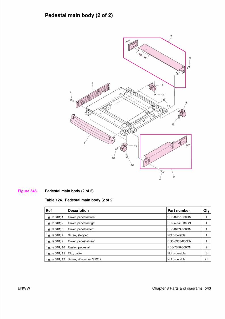
Pedestal main body (2 of 2)
Figure 348. Pedestal main body (2 of 2)
Table 124. Pedestal main body (2 of 2
Ref Description Part number Qty
Figure 348; 1 Cover, pedestal front RB3-0287-000CN 1
Figure 348; 2 Cover, pedestal right RF5-4254-000CN 1
Figure 348; 3 Cover, pedestal left RB3-0289-000CN 1
Figure 348; 4 Screw, stepped Not orderable 4
Figure 348; 7 Cover, pedestal rear RG5-6982-000CN 1
Figure 348; 10 Caster, pedestal RB3-7678-000CN 2
Figure 348; 11 Clip, cable Not orderable 3
Figure 348; 12 Screw, W washer M5X12 Not orderable 21

8/18/2019 9500 Parts Catalog
http://slidepdf.com/reader/full/9500-parts-catalog 72/84
544 Chapter 8 Parts and diagrams ENWW
Master parts lists
Alphabetical parts list
Note The master par ts tables (alphabetical and numerical) list FRUs available from HP. For a complete listof parts found in the HP LaserJet 9500 series printer, refer to the exploded view illustrations in thischapter. Parts not listed in this table might be part of a larger subassembly.
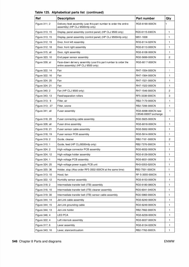
Table 125. Alphabetical parts list
Ref Description Part number Qty
Figure 326; 1 Antenna holder assembly RG5-6026-000CN 4
Figure 327; 4 Antenna holder assembly RG5-6026-000CN 4
Figure 321; 2 Block, damper RB2-7217-000CN 1
NA Cable, AC (HP CLJ 9500mfp only) RG5-5991-000CN 1
Figure 324; 23 Cable, flat RH2-5509-000CN 1
Figure 324; 24 Cable, flat RH2-5507-000CN 1
Figure 327; 2 Cable, flat RH2-5508-000CN 1
Figure 324; 17 Cable, formatter RG5-5933-000CN 1
Figure 324; 16 Cable, fuser motor RG5-5952-000CN 1
NA Cable, grounding (NHP CLJ 9500 only) RG5-5992-000CN 1
Figure 324; 18 Cable, high-voltage RG5-5937-000CN 1
Figure 324; 15 Cable, high-voltage control RG5-5940-000CN 1
Figure 347; 14 Cable holder assembly RG5-6981-000CN 1
Figure 322; 9 Cable, laser assembly RG5-6148-000CN 1
Figure 324; 27 Cable, post controller RG5-5966-000CN 1
Figure 324; 14 Cable, process cartridge RG5-5938-000CN 1
Figure 324; 22 Cable, rear holder assembly RG5-6159-000CN 1
Figure 324; 13 Cable, rear lower RG5-5919-000CN 1
Figure 324; 29 Cable, rear lower RG5-5975-000CN 1
Figure 324; 19 Cable, rear upper (HP CLJ 9500 only) RG5-5920-000CN 1
Figure 324; 19 Cable, rear upper (HP CLJ 9500mfp only) RG5-5990-000CN 1
Figure 327; 7 Cable, right rear 1 RG5-5962-000CN 1
Figure 327; 8 Cable, right rear 2 RG5-5963-000CN 1
Figure 321; 6 Cartridge, click support assembly RG5-6141-020CN 1
Figure 329; all Cassette (use this part number to order the entire assembly) RG5-5635-080CN 2
Figure 343; 17 Caster RB2-7709-000CN 1
Figure 344; 1 Caster, back RB2-7678-000CN 2
Figure 344; 2 Caster, front swivel RB3-0304-040CN 2
Figure 348; 10 Caster, pedestal RB3-7678-000CN 2
Figure 323; 9 Connector assembly RG5-5779-000CN 1
Figure 323; 16 Connector, 10P VS1-5057-010CN 1
Figure 323; 17 Connector, 20P VS1-5057-020CN 1
Figure 323; 14 Connector, 3P VS1-5057-003CN 1
Figure 323; 15 Connector, 5P VS1-5057-005CN 1

8/18/2019 9500 Parts Catalog
http://slidepdf.com/reader/full/9500-parts-catalog 73/84
ENWW Chapter 8 Parts and diagrams 545
Figure 347; 13 Connector PCA assembly RG5-6979-000CN 1
See table 85 on
page 479.
Control panel overlay NA 1
Figure 343; 6 Cover, back RF5-3644-000CN 1
Figure 343; 5 Cover, center RB2-7652-000CN 1
Figure 343; 1 Cover, front RB2-7648-000CN 1
Figure 312; 7 Cover, front left RB2-5683-000CN 1
Figure 312; 6 Cover, front right RB2-5682-000CN 1
Figure 343; 7 Cover, left RF5-3645-000CN 1
Figure 314; all Cover, left assembly RG5-6149-000CN 1
Figure 343; 4 Cover, left back RB2-7651-000CN 1
Figure 312; 16 Cover, left back assembly RG5-6111-000CN 1
Figure 312; 4 Cover, left front RB2-7335-000CN 1
Figure 312; 3 Cover, left lower RB2-5687-000CN 1
Figure 312; 1 Cover, left upper (HP CLJ 9500 only) RB2-7336-000CN 1
Figure 319; 31 Cover, rail RB2-7531-000CN 1
Figure 313; 20 Cover, rear assembly RG5-6042-000CN 1
Figure 343; 2 Cover, right RB2-7649-000CN 1
Figure 343; 3 Cover, right back RB2-7650-000CN 1
Figure 313; 8 Cover, right back RB2-7352-000CN 1
Figure 313; 23 Cover, right front RB2-7331-000CN 1
Figure 313; 5 Cover, right lower RB2-5689-000CN 1
Figure 313; 14 Cover, right upper RB2-7332-000CN 1
Figure 348; 1 Cover, pedestal front RB3-0287-000CN 1
Figure 348; 3 Cover, pedestal left RB3-0289-000CN 1
Figure 348; 7 Cover, pedestal rear RG5-6982-000CN 1
Figure 348; 2 Cover, pedestal right RF5-4254-000CN 1
Figure 313; 17 Cover, top left assembly (HP LJ 9500 only) RG5-6112-000CN 1
Figure 313; 13 Cover, top right (HP CLJ 9500 only) RB2-7321-000CN 1
Figure 323; 5 Cover, transfer cable RB2-7444-000CN 1
Figure 320; 34 Cover, transfer front RB2-7445-000CN 1
Figure 342; 5 crg (print cartridge) driver assembly RG5-5907-020CN 1
Figure 327; 6 crg driver PCB assembly (print cartridge drive) RG5-5907-020CN 1
Figure 314; 1 Dampener, left cover assembly RG5-6185-000CN 1
Figure 342; 1 DC controller PCB assembly RG5-5901-060CN new
C8546-69005 exchange
1
Figure 346; 3 Deck controller PCA RG5-6235-100CN 1
Figure 340; all Delivery cover assembly (use this part number to order the entire
assembly) (HP CLJ 9500 only)
RG5-6151-000CN 1
Figure 311; ; 1 Delivery cover assembly (use this part number to order the entire
assembly) (HP CLJ 9500mfp only)
RG5-6191-000CN
Figure 338; all Delivery feed assembly (use this part number to order the entire
assembly) (HP CLJ 9500 only)
RG5-6150-000CN 1
Table 125. Alphabetical parts list (continued)
Ref Description Part number Qty
8/18/2019 9500 Parts Catalog
http://slidepdf.com/reader/full/9500-parts-catalog 74/84
546 Chapter 8 Parts and diagrams ENWW
Figure 311; 2 Delivery feed assembly (use this part number to order the entire
assembly) (HP CLJ 9500mfp only)
RG5-6190-000CN 1
Figure 313; 15 Display, panel assembly (control panel) (HP CLJ 9500 only) RG5-6115-030CN 1
Figure 313; 15 Display, panel assembly (control panel) (HP CLJ 9500mfp only) 5851-1838 1
Figure 312; 19 Door, front left assembly RG5-6114-020CN 1
Figure 312; 18 Door, front right assembly RG5-6113-000CN 1
Figure 315; all Door, right assembly RG5-6108-000CN 1
Figure 323; 10 End paper sensor assembly RG5-5699-000CN 2
Figure 339; al Face-down delivery assembly (use this part number to order the
entire assembly) (HP CLJ 9500 only)
RG5-6017-000CN 1
Figure 322; 14 Fan RH7-1554-000CN 1
Figure 322; 16 Fan RH7-1564-000CN 1
Figure 324; 20 Fan RH7-1521-000CN 1
Figure 324; 21 Fan RH7-1522-000CN 1
Figure 340; 2 Fan (HP CLJ 9500 only) RH7-1546-000CN 2
Figure 343; 13 Feed/separation rollers RF5-3338-000CN 3
Figure 313; 9 Filter, air RB2-7170-000CN 1
Figure 313; 27 Filter, ozone RB2-7206-000CN 1
Figure 341; all Fuser assembly RG5-6098-000CN new
C8546-69007 exchange
1
Figure 318; 20 Fuser connecting cable assembly RG5-5925-000CN 1
Figure 328; all Fuser drive assembly RG5-6018-000CN 1
Figure 318; 21 Fuser sensor cable assembly RG5-5932-000CN 1
Figure 318; 19 Fuser sensor PCB assembly RG5-5914-000CN 1
Figure 319; 2 Guide, cleaner RB2-7181-000CN 2Figure 310; 1 Guide, feed (HP CLJ9500mfp only) RB2-7376-000CN 1
Figure 324; 2 High-voltage connector PCB assembly RG5-6032-000CN 1
Figure 324; 12 High-voltage holder assembly RG5-6129-000CN 1
Figure 324; 1 High-voltage PCB assembly RG5-6031-000CN 1
Figure 324; 25 High-voltage power supply PCB unit RH3-0353-020CN 1
Figure 320; 36 Holder, stop (Also order RF5-3502-000CN at the same time) RB2-7501-000CN 1
Figure 313; 10 Hood, fan RF-5-3555-000CN 1
Figure 322; 12 Humidity sensor assembly RG5-6153-000CN 1
Figure 318; 2 Intermediate transfer belt (ITB) assembly RG5-6180-080CN 1
Figure 316; 10 Intermediate transfer belt (ITB) cleaner assembly RG5-6041-040CN 1
Figure 319; 30 Intermediate transfer belt (ITB) sensor cable assembly RG5-5960-000CN 1
Figure 344; 14 Jet-Link cable assembly RG5-6240-000CN 1
Figure 344; 15 Jet-Link grounding cable RG5-6249-000CN 1
Figure 344; 13 Jet-Link holder RB2-7662-000CN 1
Figure 346; 4 LED PCA RG5-6239-000CN 1
Figure 322; 4 Left interlock assembly RG5-6037-000CN 1
Figure 317; 6 Lever assembly RG5-6134-020CN 1
Figure 343; 16 Lever, standard/custom RB2-7762-000CN 1
Table 125. Alphabetical parts list (continued)
Ref Description Part number Qty
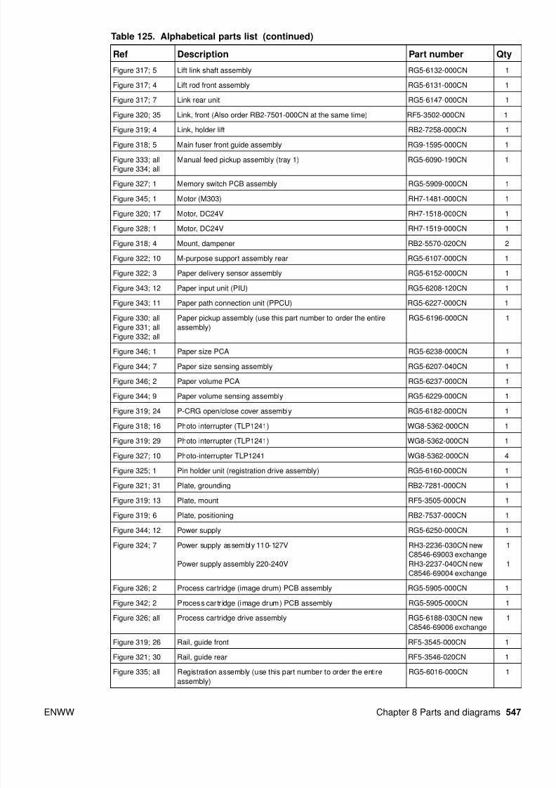
8/18/2019 9500 Parts Catalog
http://slidepdf.com/reader/full/9500-parts-catalog 75/84
ENWW Chapter 8 Parts and diagrams 547
Figure 317; 5 Lift link shaft assembly RG5-6132-000CN 1
Figure 317; 4 Lift rod front assembly RG5-6131-000CN 1
Figure 317; 7 Link rear unit RG5-6147-000CN 1
Figure 320; 35 Link, front (Also order RB2-7501-000CN at the same time) RF5-3502-000CN 1
Figure 319; 4 Link, holder lift RB2-7258-000CN 1
Figure 318; 5 Main fuser front guide assembly RG9-1595-000CN 1
Figure 333; all
Figure 334; all
Manual feed pickup assembly (tray 1) RG5-6090-190CN 1
Figure 327; 1 Memory switch PCB assembly RG5-5909-000CN 1
Figure 345; 1 Motor (M303) RH7-1481-000CN 1
Figure 320; 17 Motor, DC24V RH7-1518-000CN 1
Figure 328; 1 Motor, DC24V RH7-1519-000CN 1
Figure 318; 4 Mount, dampener RB2-5570-020CN 2
Figure 322; 10 M-purpose support assembly rear RG5-6107-000CN 1
Figure 322; 3 Paper delivery sensor assembly RG5-6152-000CN 1
Figure 343; 12 Paper input unit (PIU) RG5-6208-120CN 1
Figure 343; 11 Paper path connection unit (PPCU) RG5-6227-000CN 1
Figure 330; all
Figure 331; all
Figure 332; all
Paper pickup assembly (use this part number to order the entire
assembly)
RG5-6196-000CN 1
Figure 346; 1 Paper size PCA RG5-6238-000CN 1
Figure 344; 7 Paper size sensing assembly RG5-6207-040CN 1
Figure 346; 2 Paper volume PCA RG5-6237-000CN 1
Figure 344; 9 Paper volume sensing assembly RG5-6229-000CN 1
Figure 319; 24 P-CRG open/close cover assembly RG5-6182-000CN 1Figure 318; 16 Photo interrupter (TLP1241) WG8-5362-000CN 1
Figure 319; 29 Photo interrupter (TLP1241) WG8-5362-000CN 1
Figure 327; 10 Photo-interrupter TLP1241 WG8-5362-000CN 4
Figure 325; 1 Pin holder unit (registration drive assembly) RG5-6160-000CN 1
Figure 321; 31 Plate, grounding RB2-7281-000CN 1
Figure 319; 13 Plate, mount RF5-3505-000CN 1
Figure 319; 6 Plate, positioning RB2-7537-000CN 1
Figure 344; 12 Power supply RG5-6250-000CN 1
Figure 324; 7 Power supply assembly 110-127V
Power supply assembly 220-240V
RH3-2236-030CN new
C8546-69003 exchangeRH3-2237-040CN new
C8546-69004 exchange
1
1
Figure 326; 2 Process cartridge (image drum) PCB assembly RG5-5905-000CN 1
Figure 342; 2 Process cartr idge (image drum) PCB assembly RG5-5905-000CN 1
Figure 326; all Process cartridge drive assembly RG5-6188-030CN new
C8546-69006 exchange
1
Figure 319; 26 Rail, guide front RF5-3545-000CN 1
Figure 321; 30 Rail, guide rear RF5-3546-020CN 1
Figure 335; all Registration assembly (use this part number to order the entire
assembly)
RG5-6016-000CN 1
Table 125. Alphabetical parts list (continued)
Ref Description Part number Qty

8/18/2019 9500 Parts Catalog
http://slidepdf.com/reader/full/9500-parts-catalog 76/84
548 Chapter 8 Parts and diagrams ENWW
Figure 325; all Registration drive assembly RG5-6015-000CN 1
Figure 319; 25 Registration sensor assembly RG5-6123-020CN 1
Figure 324; 28 Regulator PCB assembly RG5-5971-000CN 1
Figure 322; 13 Right interlock assembly RG5-6036-000CN 1
Figure 321; 19 Right upper crossmember cable (HP CLJ 9500 only) RG5-5943-000CN 1
Figure 321; 19 Right upper crossmember cable (HP CLJ 9500mfp only) RG5-5974-000CN 1
Figure 323; 4 Rod, switch RB2-7354-000CN 1
Figure 320; 2 Roller RF5-3338-000CN 4
Figure 320; 3 Roller, pickup RF5-3340-000CN 2
Figure 320; 29 Scanner assembly RG5-6181-000CN 4
Figure 345; 2 Screw, M3 by 6 XB2-6300-607CN
Figure 344; 10 Screw, M4 by 6 XB6-7300-607CN
Figure 344; 11 Screw, M4 by 6 XA9-0994-000CN
Figure 343; 10 Screw, M4 by 6 XB6-7400-000CN
Figure 343; 18 Screw, M4 by 8 XA9-0732-000CN
Figure 344; 3 Screw, M5 by 12 XA9-0912-000CN
Figure 343; 8 Screw, stepped RS5-9099-000CN
Figure 343; 9 Screw, W/W, M4 by 6 XA-0994-000CN
Figure 344; 8 Screws, M4 by 8 XA9-0732-000CN
Figure 336; all
Figure 337; all
Secondary transfer assembly (T2) (use this part number to order the
entire assembly)
RG5-6179-030CN 1
Figure 322; 11 Slide arm assembly RG5-6130-000CN 1
Figure 317; 3 Soft link shaft assembly RG5-6122-000CN 1
Figure 320; 33 Spring, compression RS6-2840-000CN 1
Figure 318; 14 Spring, tension RS6-2442-000CN 1
Figure 318; 6 Sub fuser front guide assembly RG9-1596-000CN 1
Figure 319; 5 Support, cleaning front RB2-7570-000CN 1
Figure 319; 11 Support, cleaning front RB2-7515-000CN 1
Figure 319; 8 Support, side plate hinge RB2-7302-000CN 2
Figure 344; 6 Switch assembly (SW21) RG5-6206-000CN 1
Figure 321; 28 Toner cartridge cable RG5-5939-000CN 1
Figure 327; all Toner cartridge drive assembly (print cartridge drive) RG5-6022-020CN 1
Figure 316; 8 Toner cartridge lever assembly RG5-6121-000CN 4
Figure 327; 3 Toner drive cable RG5-5930-000CN 1
Figure 312; 26 Tongs, jam removal RF5-3535-000CN 1
Figure 320; 1 Torque limiter RB2-5759-000CN 1
Figure 317; 8 Transfer link front assembly RG5-6146-000CN 1
Figure 320; 6 Transfer roller assembly RG5-6178-030CN 1
Figure 343; 15 Tray 4 RG5-6212-230CN 1
Figure 345; all Tray 4 deck drive assembly RG5-6228-040CN 1
Figure 343; 14 Tray 4 vertical registration assembly (VTU/VRA) RG5-6225-050CN 1
Not shown Tray 4-to-engine stabilizing screws 0515-4318 2
Table 125. Alphabetical parts list (continued)
Ref Description Part number Qty

8/18/2019 9500 Parts Catalog
http://slidepdf.com/reader/full/9500-parts-catalog 77/84
ENWW Chapter 8 Parts and diagrams 549
Figure 312; 24 Tray face up delivery (HP CLJ 9500 only) RB2-5690-000CN 1
Figure 316; 13 Tray, catch RB2-7207-000CN 1
Figure 313; 12 Tray, delivery movable (HP CLJ 9500 only) RB2-7341-000CN 1
Figure 316; 7 Waste toner bottle assembly RG5-6040-020CN 1
Figure 316; 6 Waste toner sensor assembly RG5-6038-000CN 1
Table 125. Alphabetical parts list (continued)
Ref Description Part number Qty

8/18/2019 9500 Parts Catalog
http://slidepdf.com/reader/full/9500-parts-catalog 78/84

8/18/2019 9500 Parts Catalog
http://slidepdf.com/reader/full/9500-parts-catalog 79/84
ENWW Chapter 8 Parts and diagrams 551
Figure 343; 2 Cover, right RB2-7649-000CN 1
Figure 343; 3 Cover, right back RB2-7650-000CN 1
Figure 343; 4 Cover, left back RB2-7651-000CN 1
Figure 343; 5 Cover, center RB2-7652-000CN 1
Figure 344; 13 Jet-Link holder RB2-7662-000CN 1
Figure 344; 1 Caster, back RB2-7678-000CN 2
Figure 343; 17 Caster RB2-7709-000CN 1
Figure 343; 16 Lever, standard/custom RB2-7762-000CN 1
Figure 348; 1 Cover, pedestal front RB3-0287-000CN 1
Figure 348; 3 Cover, pedestal left RB3-0289-000CN 1
Figure 344; 2 Caster, front swivel RB3-0304-040CN 2
Figure 348; 10 Caster, pedestal RB3-7678-000CN 2
Figure 343; 13 Feed/separation rollers RF5-3338-000CN 3
Figure 320; 2 Roller RF5-3338-000CN 4
Figure 320; 3 Roller, pickup RF5-3340-000CN 2
Figure 320; 35 Link, front (Also order RB2-7501-000CN at the same time) RF5-3502-000CN 1
Figure 319; 13 Plate, mount RF5-3505-000CN 1
Figure 312; 26 Tongs, jam removal RF5-3535-000CN 1
Figure 319; 26 Rail, guide front RF5-3545-000CN 1
Figure 321; 30 Rail, guide rear RF5-3546-020CN 1
Figure 313; 10 Hood, fan RF-5-3555-000CN 1
Figure 343; 6 Cover, back RF5-3644-000CN 1
Figure 343; 7 Cover, left RF5-3645-000CN 1
Figure 348; 2 Cover, pedestal right RF5-4254-000CN 1
Figure 329; all Cassette (use this part number to order the entire assembly) RG5-5635-080CN 2
Figure 323; 10 End paper sensor assembly RG5-5699-000CN 2
Figure 323; 9 Connector assembly RG5-5779-000CN 1
Figure 342; 1 DC controller PCB assembly RG5-5901-060CN new
C8546-69005 exchange
1
Figure 326; 2 Process cartridge (image drum) PCB assembly RG5-5905-000CN 1
Figure 342; 2 Process cartr idge (image drum) PCB assembly RG5-5905-000CN 1
Figure 342; 5 crg (print cartridge) driver assembly RG5-5907-020CN 1
Figure 327; 6 crg driver PCB assembly (print cartridge drive) RG5-5907-020CN 1
Figure 327; 1 Memory switch PCB assembly RG5-5909-000CN 1
Figure 318; 19 Fuser sensor PCB assembly RG5-5914-000CN 1
Figure 324; 13 Cable, rear lower RG5-5919-000CN 1
Figure 324; 19 Cable, rear upper (HPCLJ 9500 only) RG5-5920-000CN 1
Figure 318; 20 Fuser connecting cable assembly RG5-5925-000CN 1
Figure 327; 3 Toner drive cable RG5-5930-000CN 1
Figure 318; 21 Fuser sensor cable assembly RG5-5932-000CN 1
Figure 324; 17 Cable, formatter RG5-5933-000CN 1
Figure 324; 18 Cable, high-voltage RG5-5937-000CN 1
Table 126. Numerical parts list (continued)
Ref Description Part number Qty

8/18/2019 9500 Parts Catalog
http://slidepdf.com/reader/full/9500-parts-catalog 80/84
552 Chapter 8 Parts and diagrams ENWW
Figure 324; 14 Cable, process cartridge RG5-5938-000CN 1
Figure 321; 28 Toner cartridge cable RG5-5939-000CN 1
Figure 324; 15 Cable, high-voltage control RG5-5940-000CN 1
Figure 321; 19 Right upper crossmember cable (HP CLJ 9500 only) RG5-5943-000CN 1
Figure 324; 16 Cable, fuser motor RG5-5952-000CN 1
Figure 319; 30 Intermediate transfer belt (ITB) sensor cable assembly RG5-5960-000CN 1
Figure 327; 7 Cable, right rear 1 RG5-5962-000CN 1
Figure 327; 8 Cable, right rear 2 RG5-5963-000CN 1
Figure 324; 27 Cable, post controller RG5-5966-000CN 1
Figure 324; 28 Regulator PCB assembly RG5-5971-000CN 1
Figure 321; 19 Right upper crossmember cable (HP CLJ 9500mfp only) RG5-5974-000CN 1
Figure 324; 29 Cable, rear lower RG5-5975-000CN 1
Figure 324; 19 Cable, rear upper (HP CLJ 9500mfp only) RG5-5990-000CN 1
NA Cable, AC (HP CLJ 9500mfp only) RG5-5991-000CN 1
NA Cable, grounding (HP CLJ 9500mfp only) RG5-5992-000CN 1
Figure 325; all Registration drive assembly RG5-6015-000CN 1
Figure 335; all Registration assembly (use this part number to order the entire
assembly)
RG5-6016-000CN 1
Figure 339; al Face-down delivery assembly (use this part number to order the
entire assembly) (HP CLJ 9500 only)
RG5-6017-000CN 1
Figure 328; all Fuser drive assembly RG5-6018-000CN 1
Figure 327; all Toner cartridge drive assembly (print cartridge drive) RG5-6022-020CN 1
Figure 326; 1 Antenna holder assembly RG5-6026-000CN 4
Figure 327; 4 Antenna holder assembly RG5-6026-000CN 4
Figure 324; 1 High-voltage PCB assembly RG5-6031-000CN 1
Figure 324; 2 High-voltage connector PCB assembly RG5-6032-000CN 1
Figure 322; 13 Right interlock assembly RG5-6036-000CN 1
Figure 322; 4 Left interlock assembly RG5-6037-000CN 1
Figure 316; 6 Waste toner sensor assembly RG5-6038-000CN 1
Figure 316; 7 Waste toner bottle assembly RG5-6040-020CN 1
Figure 316; 10 Intermediate transfer belt (ITB) cleaner assembly RG5-6041-040CN 1
Figure 313; 20 Cover, rear assembly RG5-6042-000CN 1
Figure 333; all
Figure 334; all
Manual feed pickup assembly (tray 1) RG5-6090-190CN 1
Figure 341; all Fuser assembly RG5-6098-000CN new
C8546-69007 exchange
1
Figure 322; 10 M-purpose support assembly rear RG5-6107-000CN 1
Figure 312; 16 Cover, left back assembly RG5-6111-000CN 1
Figure 313; 17 Cover, top left assembly (HP LJ 9500 only) RG5-6112-000CN 1
Figure 312; 18 Door, front right assembly RG5-6113-000CN 1
Figure 312; 19 Door, front left assembly RG5-6114-020CN 1
Figure 313; 15 Display, panel assembly (control panel) (HP CLJ 9500 only) RG5-6115-030CN 1
Figure 316; 8 Toner cartridge lever assembly RG5-6121-000CN 4
Figure 317; 3 Soft link shaft assembly RG5-6122-000CN 1
Table 126. Numerical parts list (continued)
Ref Description Part number Qty
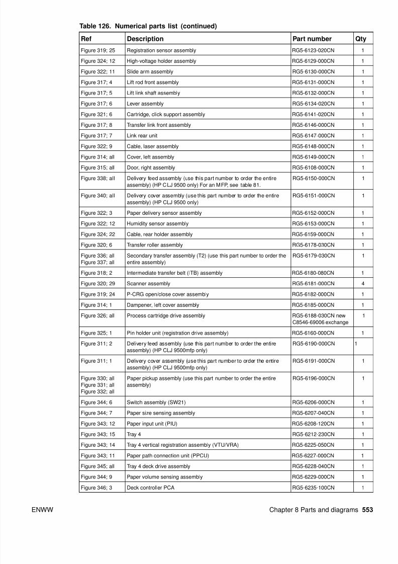
8/18/2019 9500 Parts Catalog
http://slidepdf.com/reader/full/9500-parts-catalog 81/84
ENWW Chapter 8 Parts and diagrams 553
Figure 319; 25 Registration sensor assembly RG5-6123-020CN 1
Figure 324; 12 High-voltage holder assembly RG5-6129-000CN 1
Figure 322; 11 Slide arm assembly RG5-6130-000CN 1
Figure 317; 4 Lift rod front assembly RG5-6131-000CN 1
Figure 317; 5 Lift link shaft assembly RG5-6132-000CN 1
Figure 317; 6 Lever assembly RG5-6134-020CN 1
Figure 321; 6 Cartridge, click support assembly RG5-6141-020CN 1
Figure 317; 8 Transfer link front assembly RG5-6146-000CN 1
Figure 317; 7 Link rear unit RG5-6147-000CN 1
Figure 322; 9 Cable, laser assembly RG5-6148-000CN 1
Figure 314; all Cover, left assembly RG5-6149-000CN 1
Figure 315; all Door, right assembly RG5-6108-000CN 1
Figure 338; all Delivery feed assembly (use this part number to order the entire
assembly) (HP CLJ 9500 only) For an MFP, see table 81.
RG5-6150-000CN 1
Figure 340; all Delivery cover assembly (use this part number to order the entireassembly) (HP CLJ 9500 only)
RG5-6151-000CN 1
Figure 322; 3 Paper delivery sensor assembly RG5-6152-000CN 1
Figure 322; 12 Humidity sensor assembly RG5-6153-000CN 1
Figure 324; 22 Cable, rear holder assembly RG5-6159-000CN 1
Figure 320; 6 Transfer roller assembly RG5-6178-030CN 1
Figure 336; all
Figure 337; all
Secondary transfer assembly (T2) (use this part number to order the
entire assembly)
RG5-6179-030CN 1
Figure 318; 2 Intermediate transfer belt (ITB) assembly RG5-6180-080CN 1
Figure 320; 29 Scanner assembly RG5-6181-000CN 4
Figure 319; 24 P-CRG open/close cover assembly RG5-6182-000CN 1Figure 314; 1 Dampener, left cover assembly RG5-6185-000CN 1
Figure 326; all Process cartridge drive assembly RG5-6188-030CN new
C8546-69006 exchange
1
Figure 325; 1 Pin holder unit (registration drive assembly) RG5-6160-000CN 1
Figure 311; 2 Delivery feed assembly (use this part number to order the entire
assembly) (HP CLJ 9500mfp only)
RG5-6190-000CN 1
Figure 311; 1 Delivery cover assembly (use this part number to order the entire
assembly) (HP CLJ 9500mfp only)
RG5-6191-000CN 1
Figure 330; all
Figure 331; all
Figure 332; all
Paper pickup assembly (use this part number to order the entire
assembly)
RG5-6196-000CN 1
Figure 344; 6 Switch assembly (SW21) RG5-6206-000CN 1
Figure 344; 7 Paper size sensing assembly RG5-6207-040CN 1
Figure 343; 12 Paper input unit (PIU) RG5-6208-120CN 1
Figure 343; 15 Tray 4 RG5-6212-230CN 1
Figure 343; 14 Tray 4 vertical registration assembly (VTU/VRA) RG5-6225-050CN 1
Figure 343; 11 Paper path connection unit (PPCU) RG5-6227-000CN 1
Figure 345; all Tray 4 deck drive assembly RG5-6228-040CN 1
Figure 344; 9 Paper volume sensing assembly RG5-6229-000CN 1
Figure 346; 3 Deck controller PCA RG5-6235-100CN 1
Table 126. Numerical parts list (continued)
Ref Description Part number Qty

8/18/2019 9500 Parts Catalog
http://slidepdf.com/reader/full/9500-parts-catalog 82/84
554 Chapter 8 Parts and diagrams ENWW
Figure 346; 2 Paper volume PCA RG5-6237-000CN 1
Figure 346; 1 Paper size PCA RG5-6238-000CN 1
Figure 346; 4 LED PCA RG5-6239-000CN 1
Figure 344; 14 Jet-Link cable assembly RG5-6240-000CN 1
Figure 344; 15 Jet-Link grounding cable RG5-6249-000CN 1
Figure 344; 12 Power supply RG5-6250-000CN 1
Figure 347; 13 Connector PCA assembly RG5-6979-000CN 1
Figure 347; 14 Cable holder assembly RG5-6981-000CN 1
Figure 348; 7 Cover, pedestal rear RG5-6982-000CN 1
Figure 318; 5 Main fuser front guide assembly RG9-1595-000CN 1
Figure 318; 6 Sub fuser front guide assembly RG9-1596-000CN 1
Figure 324; 24 Cable, flat RH2-5507-000CN 1
Figure 327; 2 Cable, flat RH2-5508-000CN 1
Figure 324; 23 Cable, flat RH2-5509-000CN 1
Figure 324; 25 High-voltage power supply PCB unit RH3-0353-020CN 1
Figure 324; 7 Power supply assembly 110-127V
Power supply assembly 220-240V
RH3-2236-030CN new
C8546-69003 exchange
RH3-2237-040CN new
C8546-69004 exchange
1
1
Figure 345; 1 Motor (M303) RH7-1481-000CN 1
Figure 320; 17 Motor, DC24V RH7-1518-000CN 1
Figure 328; 1 Motor, DC24V RH7-1519-000CN 1
Figure 324; 20 Fan RH7-1521-000CN 1
Figure 324; 21 Fan RH7-1522-000CN 1
Figure 340; 2 Fan (HP CLJ 9500 only) RH7-1546-000CN 2Figure 322; 14 Fan RH7-1554-000CN 1
Figure 322; 16 Fan RH7-1564-000CN 1
Figure 343; 8 Screw, stepped RS5-9099-000CN
Figure 318; 14 Spring, tension RS6-2442-000CN 1
Figure 320; 33 Spring, compression RS6-2840-000CN 1
Figure 323; 14 Connector, 3P VS1-5057-003CN 1
Figure 323; 15 Connector, 5P VS1-5057-005CN 1
Figure 323; 16 Connector, 10P VS1-5057-010CN 1
Figure 323; 17 Connector, 20P VS1-5057-020CN 1
Figure 318; 16 Photo interrupter (TLP1241) WG8-5362-000CN 1
Figure 319; 29 Photo interrupter (TLP1241) WG8-5362-000CN 1
Figure 327; 10 Photo-interrupter TLP1241 WG8-5362-000CN 4
Figure 343; 9 Screw, W/W, M4 by 6 XA-0994-000CN
Figure 343; 18 Screw, M4 by 8 XA9-0732-000CN NA
Figure 344; 8 Screws, M4 by 8 XA9-0732-000CN
Figure 344; 3 Screw, M5 by 12 XA9-0912-000CN
Figure 344; 11 Screw, M4 by 6 XA9-0994-000CN
Figure 345; 2 Screw, M3 by 6 XB2-6300-607CN
Table 126. Numerical parts list (continued)
Ref Description Part number Qty

8/18/2019 9500 Parts Catalog
http://slidepdf.com/reader/full/9500-parts-catalog 83/84
ENWW Chapter 8 Parts and diagrams 555
Figure 344; 10 Screw, M4 by 6 XB6-7300-607CN
Figure 343; 10 Screw, M4 by 6 XB6-7400-000CN
Table 126. Numerical parts list (continued)
Ref Description Part number Qty

8/18/2019 9500 Parts Catalog
http://slidepdf.com/reader/full/9500-parts-catalog 84/84


