
A Handbook onA Handbook onA Handbook onA Handbook on
DIESEL HYDRAULIC MULTIPLE UNITDIESEL HYDRAULIC MULTIPLE UNITDIESEL HYDRAULIC MULTIPLE UNITDIESEL HYDRAULIC MULTIPLE UNIT
By
B.Rajender, Senior Loco Inspector,
DIESEL LOCO SHED – MOULA – ALI, HYDERABAD DIVISION
SOUTH CENTRAL RAILWAY

2
INDEX
1. DHMU DATA
2. EACH UNIT CONSIST OF 3 COACHES
3. DHMU
4. PAC
5. MASTER CONTROLLER
6. AUTOMATIC SAFETY MEASURES
7. THE GUARD’S CONTROL SWITCH
8. THE VIOTH T211 R2 TURBO TRANSMISSION
9. EMERGENCY BELL
10. BELL CODE SYSTEM & BELL CODE
11. TELEPHONE
12. POLLUTION CONTROL
13. SHACO COUPLING
14. DRIVER’S CONTROL SWITCH BOX (DCS)
15. LED
16. GUAGE PANEL
17. METER PANEL
18. SPEEDOMETER
19. RELAYS & TIMERS
20. CONTROL AND AUXILIARY CIRCUITS MASTER CONTROL BREAKERS
21. ENGINE LOCAL ON AND OFF CONTROL
22. SWITHC OFF SEQUENCE
23. FAULT CONDITIONS
24. DE-ENERGISATION OF FAULT RELAYS
25. REMOTE OPERATIONS
26. DIRECTION SELECTION
27. MOVEMENT OF THE TRAIN
28. SYSTEM ABNORMALITIES
29. STOPPING OF THE TRAIN
30. LAMP TEST FACILITY
31. READY TO START
32. REMOTE ENGINE ON/OFF OPERATION
33. BUILDING UP OF AIR PRESSURE
34. PARKING BRAKE ON/OFF
35. DRIVER INTERLOCK RELAY
3
36. CONTRL SUPPLY INDICATION
37 .TROUBLE SHOOTING
38.TROUBLE – CAUSE – REMEDY
39.BELT DRIVES
40.ENSURE AFTER CRANKING
41.ABNORMALITY RELAYS
42.DHMU DRIVERS TO ENSURE
43.HOW TO START THE DHMU
44.DON’T ON DHMU FOR DRIVERS
45.HOW TO STOP THE DHMU

4
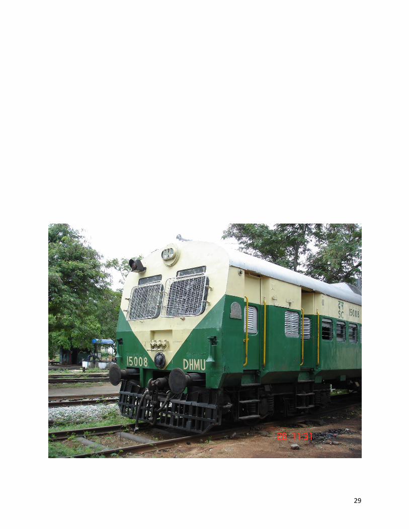
DIESEL HYDRAULIC MULTIPLE UNIT
(DHMU)
1. DATA: -
Track: 1676 mm
Composition: 3,6 or 9 coaches only duly consisting of 1 DPC,
1 TC and 1 DTC.
DPC – Driving Power Car
TC – Trailing Car.
DTC – Driving Trailing Car.
Estimated Weight DPC – 68 Te.
TC – 60 Te.
DTC – 60 Te.
Wheel arrangement: 1 A A 1.
Engine Make: Cummins Engine Nomenclature NTA – 855.
Firing Order: 1-5-3-6-2-4
Bore and Stroke 140 mm [5.5”] x 152 mm[6.0].
Maximum RPM 2450 (OSTA set at 2350 rpm)
Power Output of Engines 2 x 345 HP at 1900 RPM.
Transmission System: Hydro dynamic (T211 rz).
Clearance above rail level: 102 mm.
Brakes: Twin pipe graduated release air brake system.
Auxiliary Alternator
Capacity: 12 KW
Output Voltage: 130 V ± 5 %
Current: 92.3 Amps.
Minimum speed for pull out: 900 RPM
Drive ‘V’ belt drive.
Number of belts 4
5
Maximum pressure of
Compressor: 7 Kg/Cm2
Drive of Compressor: ‘V’ belt driver with 2 belts.
Cooling: Inter cooler provided.
Cooling System: Hydrostatic from drive.
Control and Auxiliary System: Alternator 110 V DC ‘V’ belt drive.
Rating: Continuous.
Transmission Output: 340 HP at 1900 RPM.
Maximum Operating Speed: 100 KMPH.
Compression type: 2 EC with 2 belts, ‘V’ drive.
Gear Box Type: Axle drive V17(M).
Gear Ratio: 4.07:1.
Starter Battery: Mono Block Lead Acid.
Voltage: 24 V (3.8)
Capacity: 290 Amps/Hour.
Control Supply Battery Type: Mono Block (VRLA).
Make: Amar Raja Batteries, Tirupathi.
Voltage: 110 V.
Capacity: 120 Amps/Hour.
Fuel Per One Hour per Power Pack in Idle condition : 6.5 Lts.
Minimum fuel oil balance 200 Lts.
Maximum fuel oil balance 1400 Lts.
Axle gearbox maximum oil
Capacity: 14 Lts.

6
Lubricants Used
S.No
Name of the Manufacturer Brand Name
1 Castrol Ltd. Beusol Super 20W-40
2 Tide Water Oil Company Ltd. Veedol 20W-40CD
3 Gulf Oil Company Ltd. Super Duty Motor Oil 20W-40
4 Hindustan Petroleum Corporation Ltd.
Hylube – Extra 20 W-40 Hylube (ICE category) LL 15W-40
5 Indian Oil Corporation Ltd. Servo Petroleum 20W-40
6 Chemoleum DLO 200 CD & SAE 20W-40
7 Bharat Petroleum Corporation
Ltd.
Ultra Super (TCA) 20W-40
Bharat Ultra Supreme 15W-40 ( CE
Category)
8 Pennzoil India Ltd. Pennzoil Long Life 20W-40
9 ELF Lubricants India Ltd. ELF performance – JDC 20W-40
Product Manufacturer Brand Name
Compressor 2EC-38 (Sump capacity 7
Liters)
IOCL Servo System – 317
Transmission T 211 RZ
(Sump capacity 70 Liters without piping &
cooler)
a) Caltex b) ESSO c) Indian oil d) Shell e) Elf
� Torque fluid – 32
� Esso – Torque fluid –
N-45 � Servo – Torque – 20
� Shell Tecula Oil -32 � ELF Transmission –
32
Axle Drive (Sump capacity 12 Liters)
a) HPCL b) BPCL c) Indrol d) IOCL
� HP gear oil EP-90 � Bharat spiral 90 – EP
� H – C-8- - W/90
� Servo Gear HP-90

7
2. Each Three-Coach Unit Consists of: -
a) 2 power packs
b) 2 transmission units
c) 2 axle drive gear boxes
d) 1 fuel tank of 1400 litres capacity
e) 1 or 2 WRA (Water Raising Apparatus – From this apparatus water will be
pumped to expansion tank with the help of 2.5 Kg/Cm2 of MR pressure on
the surface of water level)
f) 4 Cardon shafts
3. DHMU: -
Its full form is Diesel Hydraulic Multiple Unit. A versatile design
produced in 3 coaches, 6 coaches or 9 coaches formation. The study growth
of commuted traffic and to meet such demands for fast growing cities and
industrial towns in India, resulted in demand for sub-urban and short
distance passenger services introduced in the most economical and fuel
efficient rate.
To meet this demand the Indian Railways has geared up the resources
for the production of DHMU, which has the operational features of fast
acceleration and fast braking with air brake system enabling it to function as
stopping train but maintaining the average speed to match fast mail and
express trains. So that it does not slow down the speed .
The DHMU’s are of a self-propelled unit consisting of one Driving Power
Car (DPC), one Trailing Car (TC) and one Driving Trailing Car (DTC). The
control systems are made suitable for multiple operations of one, two and
three unit formations as mentioned above and cater to the demands of
commuted traffic on both the electrified and non-electrified sections.
The DHMU’s are designed for 101 seating capacity of passengers in
both DPC & DTC, 108 passengers in TC’s and liberal space for standing
passengers have also been provided, capable of carrying as many as 800
passengers under dense and crush load conditions. The coaches have been
provided with

8
Cushioned seats and tinted glasses on the windows for coolness, adequate
fans and florescent lights are also provided for the better comfort of the
passengers. The vestibule provided between the coaches enable the
passengers to board the train for the occupation of seats anywhere in the
train and also to detrain from any door of the train.
4. PAC (Passenger Alarm Control): -
The Passenger alarm system provided and used in this train is a
unique one. The system is provided with external indicator, one on each
sidewall of the coach, which will give you a visible indication on the coach via
electrical limit switches provided on the outside end walls. When the alarm
has been pulled, the visible indication and the alarm bell will ring. This can
be reset to its normal position by operating of mechanical hand operation on
each end wall after guard’s attention to that compartment. Then the train
can be brought to halt at a same place by the discretion of the driver and
guard duly eliminating the brake binding on the formation.
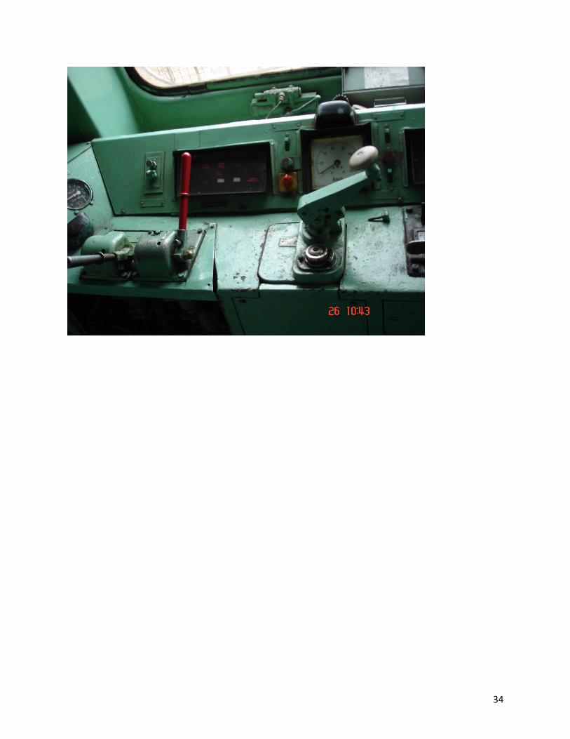
5.Master Controller: -
The commands for driving and discretion of DHMU are issued from the
master controller. There are two handles, 1) Train operating handle 2)
Reversing lever.
The train operating handle (throttle) with neutral position and 8
nothing positions i.e. 1 to 8 to energizes train line combination and the other
one is reversing lever for direction selection.
The reversing lever can be taken out of the reversing slot, only when
the train-operating handle is set to zero. The reversing lever is also called
as DCS (Direction Controller Switch).
The master controller is also mechanically interlocked in such a way
that it will not be possible to operate the train operating handle (throttle)
unless the reversing handle seated in its seat to move either Forward or
Reverse direction depending upon the direction of the drive selected. The
help of a double dog clutch does the main component of the reversing unit
for changing the direction and direction of travel.

9
Double Dog Clutch is provided inside the transmission unit and which can
only be operated at stand still. The actuation of sliding selector on the
sleeve is effected via the pneumatic reversing selector. In order to actuate
the reversing unit on the transmission the following requirements have to be
fulfilled.
a) The master controller should be in zero position.
b) The diesel engine is in idle condition.
c) The turbo transmission has been drained.
d) The vehicle must be stationary.
e) The compressed air has a minimum pressure of 4.5 Kg/Cm2.
The vehicle controlling is designed in such a way that reversing can only
be performed if all the above said requirements have been fulfilled.
6. Automatic Safety Measures: -
A dead man’s handle is also provided along with train operating handle and it’s knob to
be pressed during driving mode. If the dead man handle is released during driving mode
auxiliary air brake will be applied via relay valve provided inside the master controller which is
mechanically interlocked with dead man’s handle, thus the train comes to a halt automatically.
7.The Guard’s Control Switch:-
There is a new additional control provided on DHMU. A key operated
four pole switch is provided where two poles are used for switching on and
off compartment lights and fans under guard’s control and one pole for
interchanging between guard and driver to ascertain both are actually
(physically) present in coach, this eliminates the possibility of ‘guard left
behind’ cases.
8. The Voith T211 RZ Turbo Transmission: -
The function of a transmission to transmit the engine power to the
rails over the widest speed with minimum loses. The turbo transmission is a

10
fully automatic transmission for rail cars with diesel engine drive. The
present transmission is of converted coupling version. Its primary
components are a hydrodynamic torque converter and hydrodynamic
coupling which transmits power through the mass forces of the operating
fluid.
The torque converter and the fluid couplings are designed for
operation at different speed ranges (1st speed and the 2nd speed
respectively). The speed offering maximum efficiency in power transmission
for the prevailing speed is automatically engaged and taken –off is smooth
and without jerks and shifts from torque converter to fluid conversion
operator are effected equally smooth and without interruption of
transmission.
The circuits are automatically engaged and disengaged according to
the position of the master controller to control the speed via the main
control of the piston. The change over from converter to coupling takes
place at full load about 60-68 KMPH of maximum speed.
DHMU operation is very economical in terms of fuel economy. There
are two power packs of 345 HP of power engine consuming approximately
35 liters of HSD oil for the continuous run of 1 hour with full occupancy. The
fuel efficiency is more when the transmission change takes place as
mentioned above. It is an ideal and efficient operating temperatures are 90o
C to 110o C.
9. Telephone: -
A telephone is provided in both the driving cabs by introducing the
spare leads provided in MU jumper cables. This is specifically enables the
GDR to make conversation with each other even while on run and take lot of
train operational decision and convey each other.
10. Emergency Bell: -
An emergency bell is provided at both end cabs and with in reach of
driver and guard. On operation of this bell a loud continuous bell is heard in
both the driving cabs drawing each others attention for immediate reaction
to stop the train or to take safety measures.

11
10. Bell code system:-
A bell code system is provided for starting, stopping, acknowledging
the signals between the driver and guard in accordance with SR 4.51 is
made possible. The provision has minimized the use of conventional hand
signals.
11.Bell Code System
Bell
Code Meaning/Action
X Stop the train.
XX Start the train.
XXX a) Guard required by driver. b) Given on run by motorman – guard should acknowledge it
and apply his van valve brake to assist motorman in stopping the train.
XXXX Protect the train in rear.
XXXXX Commencement or completion of combined brake test.
X – X a) After passing caution spot. b) During combined brake test GDR may use this code to draw
each other’s attention in case of any lapse or abnormality.
XX – XX Passing automatic signals at ON. XXX – XXX Motorman not to exceed the prescribed speed. XXXX – XXXX Guard leaving the cab.
12. Pollution Control: -
This is an eco-friendly unit releasing the least possible minimum
exhaust, which anybody can feel. The environmental pollution is reduced to
large extant compared to the other diesel locomotives operation.
13. Schako Coupling: -
This coupling provided and eliminates slacks, gaps between the
coaches and the coupling enabling the units to stop and run & start without
any jerks on this account.
14. Driver’s Control Switch Box (DCS): -

12
It consists of 1 DCS program switch with 10 poles (8 N/o + 2 N/c) and
the switch is operated by inserting the driver’s key, this removable key is
inserted in position when driver is available in driving cab.
There are 16 numbers of lever operated cab switches, 11 numbers of
return spring loaded switches are provided for the operations like engine
start, engine stop, control supply on, parking brake on-off, lamp test,
instrument lamps, test sequence switch (TSS), building of fast air pressure
and reset/ready to start and 2 switches are spare for future use.
The top rows of switches are located in the off position of the DCS and
DCS key is inserted and operated by the driver. 2 numbers of 110 V/10 W
lamps are provided and below the nameplates are provided for clear visibility
for driver during the night service.
SS PANEL (DPC)
SS1 SS2 SS3 SS4 SS5 SS6 SS7 SS8
Parking Brake ON
Control Switch
Engine 1 ON
Engine 2 ON Engine 3 ON
Engine 4 ON
Engine 5 ON
Engine 6 ON
Lamp Test Fast Building
Air
Ready to Start
Instrument Lamp
Spare Test Sequence Switch
Spare DHMU Halt
SS9 SS10 SS 11 SS12 SS13 SS14 SS15 SS16
15. LED (Light Emitting Diode) Indicating Panels: -
There are two panels of 6 LED indications are provided and each one is
provided for identification of engine ON and Reversing ON indications.
There are two panels of 10 LED indications in which control indications
like 1) Traction Control supply on, 2) Drive function released, 3) Engine idle,
4) Engine tripped, 5) Parking brake applied, 6) Auxiliary alternator failure
no.1, 7) Auxiliary alternator failure no. 2, 8) Common Annunciator and two
spare LED’s for future use.
The other 10 LED indications are for fault indications like
1) HCWT (Hot Cooling Water Temperature)
2) HLOT (Hot Lube Oil Temperature)

13
3) HTOL (Hot Transmission Oil Temperature)
4) LLOP (Low Lube Oil Pressure)
5) OST (Over Speed Tripping)
6) LCWS (Low Cooling Water Level)
7) RI (Reverser Incomplete) and 3 spare LED’s for future use.
One panel with 2 LED indications are provided in engine to identify in
which engine circuit the sensitive faults are occurred.
16. Gauge Panel: -
There are gauges for lube oil pressure, water temperature,
transmission oil temperature, hour meter, engine RPM digital tachometer,
battery charging ammeter for individual engines 1 & 2 separately are
provided on panel in driver’s cab to monitor the condition of individual
engine.
17. Meter Panel: -
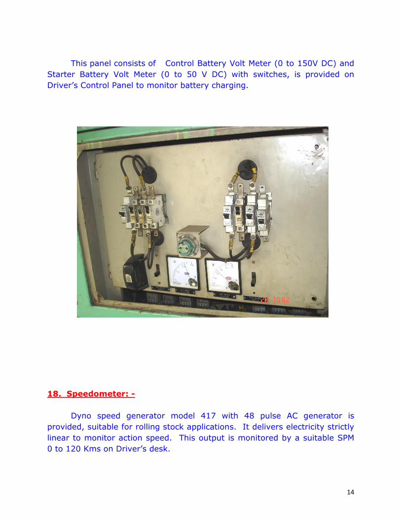
14
This panel consists of Control Battery Volt Meter (0 to 150V DC) and
Starter Battery Volt Meter (0 to 50 V DC) with switches, is provided on
Driver’s Control Panel to monitor battery charging.
18. Speedometer: -
Dyno speed generator model 417 with 48 pulse AC generator is
provided, suitable for rolling stock applications. It delivers electricity strictly
linear to monitor action speed. This output is monitored by a suitable SPM
0 to 120 Kms on Driver’s desk.

15
Now all the DHMU s are provided with MRT 918 (MEDHA) speed
recorders.
19. Relays and Timers: -
There are three sets of relay panels.
1) 110 V DC relay panel (Common for power packs 1 & 2).
2) 24 V DC relay panel for power pack 1.
3) 24 V DC relay panel for power pack 2.
20. Control and Auxiliary Circuits Master Control Breakers: -
There is a set of 110 V DC Master Control Breakers for control circuits;
auxiliary circuits and 24 V DC panels for individual engine controls are
provided separately on panels behind the Driver’s seat for easy
maintenance.
21. Engine Local ‘ON’ and ‘OFF’ Control: -
There is a 29 Amp/Hr, 24 V starter batteries with lead acid mono
blocks are provided in starter motor circuits with battery isolating switch CS-
2 (Control Switch.2).
A Starter Control switch (Engine Mounted) is provided to protect
against over cranking. The Magnetic switch is used for closing the main
contactor for energizing cranking servomotor. Battery charging alternator is
provided for starting battery charging while engine is running and ammeter
is provided in gauge panel for the indication of charging current.
A local ON/OFF and reset push buttons are provided in a box near each
engine for local ON/OFF operations.
When isolating switch (CS 2) is closed, the 24 V supply is ready for
engine starter motor and respective controls.
When local/remote rotary switch is operated to local position or when
local push button is pressed (near under frame), a relay LRR gets energized
in Driver’s Cab and its N/o contact are closed to energize relays for low lube
oil pressure and over speed. R41 & R 51 for engine 1 and R42 & 52 for
engine 2.

16
The contactors are in series with sensors for low lube oil pressure and
low cooling water level, over speed relays and relays R51 & R61 are for low
hydraulic oil level and low cooling water level (common for engine 1 & 2) to
protect engine during starting.
When local ON push button is pressed, local ON/OF relays R 81 is
energized and retained through its N/o contactor. At the same time 24 V
supply to starter motor is fed through magnetic switch via starter control
switch. When engine picks up speed and lube oil Pressure is built up, the
N/c contactor of starter control switch‘s interlock will open and 24 V supply
for the starter motor will get cut off. Same times idling solenoid valve SOV
51 is also energized to run the engine at idle speed (at 600 rpm).
The timer TR 11 & TR 12 for engine 1 & 2 will ensure that not more
than 3 starts of maximum period of 10 seconds are made.
In case there are no discrepancies and lube oil pressure builds up to its
optimum level, engine will continue to run at idle speed and hour meter
monitors it.
22. Switch OFF Sequences: -
The engine can be switched off by pressing the engine off push button
on local push button stationed near engine, which de-energizes the relay R
81. This results in operating of its contact in circuit of solenoid valve 51
pertaining to shut down valve. This in turn leads to cutting down of fuel to
diesel engine and engine stops.
23. Fault Conditions: -
During diesel engine running in local mode if anyone of the relays of
low lube oil pressure, low cooling water level, over speed and R41, R51, R
61 for engine no.1 and R42, R52, R62 for engine no.2 will get de-energized
and fault monitoring relays FC21 for engine 1 & FC22 for engine 2 will
energies, in turn de-energized the shut down circuit of diesel engine.
24. De-energizing of Fault Relays: -
When engine local/remote rotary switch is moved from Local position to OFF,
the 24 V supply to fault relay is switched off and relays get de-energized.

17
24. Remote Operations: -
When local / remote switch is selected to remote operation the engine
circuit is kept ready for engine remote operations.
25. Direction Selection: -
Keep MC (Master Controller) to zero position with dead man’s control
handle in pressed position and select reverse handle for either forward or
reverse.
The forward/reverse dog clutches are preset in the transmission to
match the directions of PP1 & PP2 in such manner that the control signals
make through their respective limit switches in transmission energizes the
relays C31, C32 or C41, C42 momentarily, which in turn energizes the
solenoid valves SOV 81, SOV 82 (Stand Still Detectors) or SOV 101, SOV
102 for forward direction depending upon the direction selective signal is
given.
As the piston starts moving in the transmission relays S51 & S52 de-
energizes and Reversing-ON indication disappears, within 2-3 seconds the
piston movements complete the direction selected and then the other end
limit switch is pressed inside the transmission and relays C21 & C22 once
again energizes by the appearance of Reversing-ON indication. Once a
particular direction is selected the transmission is automatically ready to
receive the signal for selecting the other direction through the actuation of
respective switches.
26. Movement of the Train: -
Actuation of the Master Controller from notch 1 to 8, relays C101/C102
get energized, which in turn actuates SOV 71/SOV72 and transmission filled
with oil and engine drive is connected to the wheels and train accelerates.
For any of the faults or abnormalities the relays FC31/FC32 get energized,
there by switching OFF the SOV 71 / SOV 72 and the respective transmission
comes to neutral (i.e. the oil is emptied and transmission comes to neutral),
notching also gets de-energized via FC31 / FC32.

18
For positions 1 to 8 of the Master Controller relays C51 / C52 and
C81 / C82 will get energized in local sequences there by energizing the
solenoid valves of the multiple unit throttle controller (MUTC) mounted on
engine in a similar logic way SOV11/ SOV 42. From notch 5 onwards SOV
61/SOV 62 (Solenoid Valves for primary influence) gets energized and
transmission works in Coupling Mode from Torque Converter Mode to get
optimum efficiency.
27. System Abnormalities: -
Each power pack is protected against the following faults automatically
with 7 faults along with auxiliary alternator 1 & 2.
They are as follows….
S.No Fault Result
1 High cooling water temperature Engine comes to idle (Transmission to
Neutral)
2 High transmission oil temperature
Engine comes to idle (Transmission to Neutral)
3 Reversing incomplete Engine comes to idle (Transmission to Neutral)
4 Low lube oil pressure Engine trips (Transmission to Neutral)
5 Over speed (Engine) Engine trips (Transmission to Neutral)
6 Low hydraulic oil level Engine trips (Transmission to Neutral)
7 Low cooling water level Engine trips (Transmission to Neutral)
6 & 7 � A common fault for Power Packs 1 & 2
With these 7 faults along with auxiliary alternators no. 1 & 2 failure,
the respective fault LED illuminates, power pack display in no. 1 & 2 also
illuminates and a common annunciation LED glows along with two side
lamps (UFIL) of respective DPC (i.e. unit fault indication lamp) to exactly
locate faulty PP. Depending upon the nature of the fault the indication of the

19
Engine Idle or Engine Trip gets illuminated on control indicator. In case of
Engine Trip indication respective Engine On disappears.
28. Stopping The Train: -
By actuating the selector switch SS 16 (DHMU
Halt) all the engines will get switched off simultaneously. Relay S2 is
energized momentarily and relay S11 / S12 will get de-energized, there by
switching off the relays R91/R92 and then engine stops working.
Note: - Selector with 14 test sequences is not to be used by the Driver. It is
only of the maintenance staff to check relay logic without train movement.
29. Lamp Test Facility: -
A lamp test switch is provided near Driver’s control switch box and is
pressed to glow all the lamps at initial to ascertain that all LED’s are
working.

20
30. Ready To Start: -
When control switch in Driver’s control box is in off position and Master
Controller is not operated and when ready to start the train, then push the
push button switch (i.e. Ready to Start switch – SS 11) in Driver’s control
box, the train line will get energized via N/c contacts of Master Controller.
Relay RR connected to train line energizes and its N/o contacts are closed in
power pack 1 & 2 circuit to energies the fault sensing relays like
• High cooling water temperature (R 11, R 12)
• High transmission oil temperature (R 31, R 32)
• Reversing incomplete (R 71, R 72)
• Low lube oil pressure (R 41, R 42)
• Over speed relays (R 51, R 52)
• Low hydraulic oil level (R 21, R 22) &
• low cooling water level relays R 61, R 62 for engine 1 & 2
And retained via their respective contacts in series with sensors for above
faults before engine starting. During the 3 faults high cooling water
temperature, high transmission oil temperatures & reversing incomplete.
The engine will come to idle and transmission to neutral signal and due to
low lube oil pressure, over speed, low cooling water level and low hydraulic
oil level the engine will trip and transmission comes to neutral.
31. Remote Engine ON/OFF Operation: -
To avoid starting of both the engines simultaneously, the N/c
interlocks of unit are connected to a push button in such a way that only one
engine can start at a time, when the spring return switch SS 3 in Driver’s
Control Switch Panel to keep engine 1 in ON condition through a 110 V
supply relay S 11 energizes, which in turn a 24 V supply relay R 91 will
energies the remote ON/OFF control by a relay, there by remote engine
starts via energizing of relay S 11 and R 91.

21
The N/o contacts of engine off relays S 2 to hold the energized series
relays S 11 & S 12 for keeping engines ON, then the respective engine ON
indication will glow on cab desk. When DHMU halt push switch is pressed in
DCS panel for remote off relay S 2 will energies and trips all engines as
whole in the formation.
32. Building Up of Air Pressure: -
When a spring return switch SS10 on DCS is operated, relays S51 &
C51 for power pack 1 and S52 & C 52 for power pack 2 energies. The N/c
contactor of S51/S52, in circuit C101/C102 will restrict energizing of
solenoid and transmission not filled. When C51/C52 energizes the speed
increases from 600 to 1900 RPM without load, then the main reservoir is
charged quickly via belt driven compressor and at 1000 RPM, 7 Kg/Cm2
pressure in MR gauge will been seen.
33. Parking Brake ON/OFF: -
When parking brake switch SS1 in DCS panel is switched ON the
parking brake cylinder is charged to release parking brake. A pressure-
operated brake is provided to park the vehicle at gradient when standing for
signal or at destination.
34. Driver Interlock Relay: -
When guard’s control switch is operated in Guard’s Control Switch
Panel in other cab, the Driver’s interlock relay S1 is energized in leading cab
via pressure switches, brake pipe control governor and parking brake closed
at 3.6 Kg/Cm2 respectively and parking then N/o interlocks of this relay gets
energize one in indication circuit to indicate ‘Drive function released’ and
other one master control to ‘Drive function’.
35. Control Supply Indication: -
When control switch is ON in DCS, the LED indication in cab lit to indicate
‘Control Supply ON’ and unit is ready for movement.

22
36. Trouble Shooting
Guidelines for Trouble Shooting in Electrical Control System
The below mentioned paragraphs describe briefly about the guidelines
for trouble shooting procedure in step by step to over come the
abnormalities which may appear in controls and instrumentation system
which may appear in diesel hydraulic multiple unit.
General Checks: -
1) 110 V DC supply should be available and indicated by Voltmeter on
Driver’s Control Panel.
2) 24 V DC supply shall be available and indicated by Voltmeter on Driver’s
Control Panel.
3) All the miniature circuit breakers shall be switched to ‘ON’ position.
Abnormality Probable Cause / Remedy
Engine Does Not
Start
1) ECS control switch CS 11/12 should be kept in proper position (i.e. remote).
2) Relays R81/82 or R91/92 should be ON. 3) Relay S11/12 should be ON for respective power packs. 4) Open the circuit between N/c contacts of Timer Relay (TR
11/12) to engine starter.
5) Solenoid valves (SOV 51/52) should be in energised condition.
6) Test sequence switch SS 14 should be in OFF position.
Appearance
of fault on Indicator
1) Actuate ‘Key switch control’ to its original position (i.e. in OFF position).
2) Put MC to zero position. 3) Actuate key switch ‘Ready to start’ (SS 11) once again. 4) Observe whether the fault indicating windows are
switched off or otherwise it may illuminates. 5) Observe the location of the fault (on power pack 1 & 2)
on control display.
6) Observe the respective gauge (Pressure/Temperature) of respective power pack as a cross check.
7) Check the 24 V DC coil of the respective faulty relay for open circuit/burnt out.
8) Check the wiring for open circuit between the respective engine/transmission sensors to fault relay.
9) After attending the fault, if the system does not get reset (i.e. fault indicator continues to show the fault) check
the healthiness of the respective relay (RR1, RR2, RR3).
23
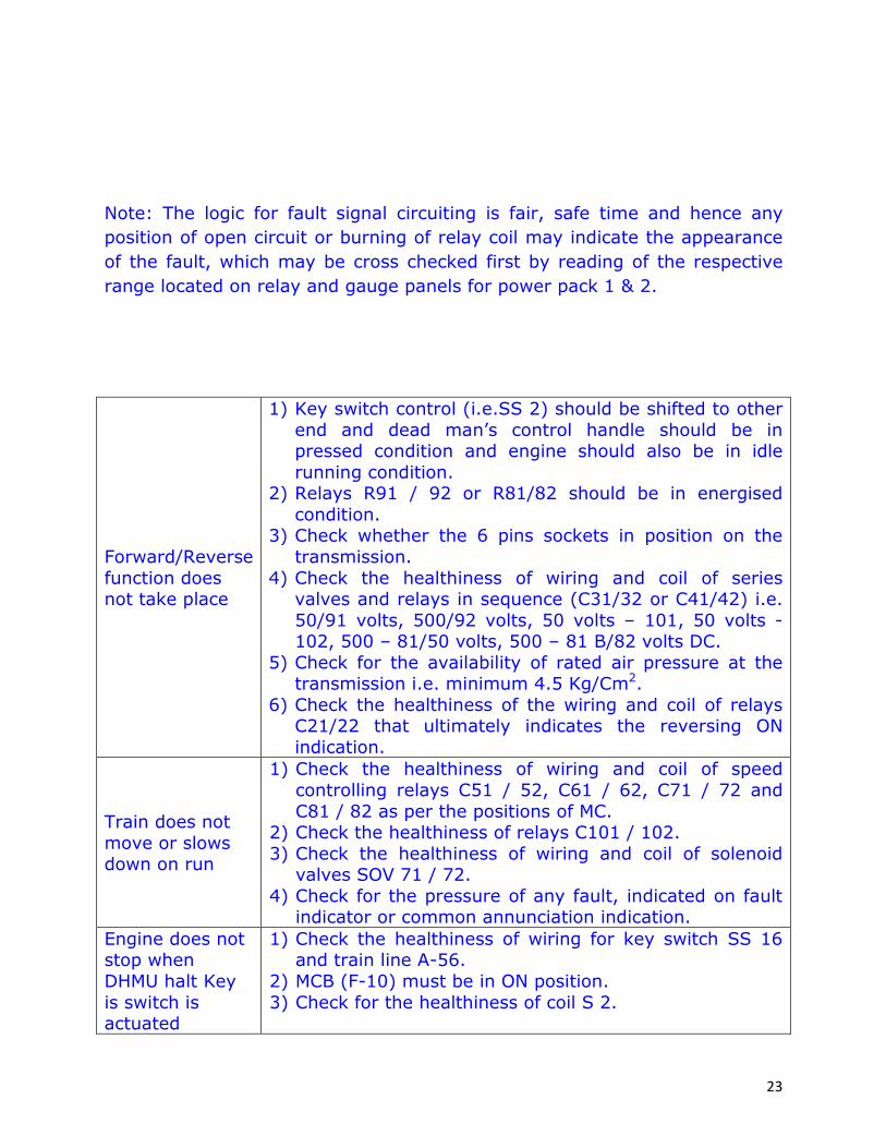
Note: The logic for fault signal circuiting is fair, safe time and hence any
position of open circuit or burning of relay coil may indicate the appearance
of the fault, which may be cross checked first by reading of the respective
range located on relay and gauge panels for power pack 1 & 2.
Forward/Reverse
function does not take place
1) Key switch control (i.e.SS 2) should be shifted to other end and dead man’s control handle should be in pressed condition and engine should also be in idle
running condition. 2) Relays R91 / 92 or R81/82 should be in energised
condition. 3) Check whether the 6 pins sockets in position on the
transmission.
4) Check the healthiness of wiring and coil of series valves and relays in sequence (C31/32 or C41/42) i.e.
50/91 volts, 500/92 volts, 50 volts – 101, 50 volts -102, 500 – 81/50 volts, 500 – 81 B/82 volts DC.
5) Check for the availability of rated air pressure at the transmission i.e. minimum 4.5 Kg/Cm2.
6) Check the healthiness of the wiring and coil of relays C21/22 that ultimately indicates the reversing ON
indication.
Train does not
move or slows down on run
1) Check the healthiness of wiring and coil of speed controlling relays C51 / 52, C61 / 62, C71 / 72 and
C81 / 82 as per the positions of MC. 2) Check the healthiness of relays C101 / 102. 3) Check the healthiness of wiring and coil of solenoid
valves SOV 71 / 72.
4) Check for the pressure of any fault, indicated on fault indicator or common annunciation indication.
Engine does not stop when
DHMU halt Key
is switch is actuated
1) Check the healthiness of wiring for key switch SS 16 and train line A-56.
2) MCB (F-10) must be in ON position.
3) Check for the healthiness of coil S 2.

24
Vehicle fails to pull away
although brakes are released and
MC set to traction
1) Too little oil in transmission.
2) Oil too cold (guaranteed tractive effort not obtained until oil is warmer than 70o C.
3) Incorrect or over aged oil. 4) Water in oil (where oil is cooled by heat exchanger).
5) MC position remains in Idle position. 6) Main control piston or pilot control piston sticking. 7) Grooved rings on pilot control piston leaking. 8) No control air pressure or pressure is too low.
9) Filling pump pressure is low, even through oil is in
order.
Inadequate
Tractive Effort
1) Too little oil in transmission. 2) Water in oil (where oil is cooled by heat exchanger.
3) Main control piston sticking in speed-II. 4) Incorrect or over aged oil. 5) Engine does not reach its full load speed. 6) Air pressure drops off. 7) Labyrinth seals worn out, filling pump pressure at test
point adequate but drops of rapidly.
MR & BP
Pressure not Building Up.
1) Check for MR leakage if any. 2) Ensure trailing DPC/DTC A9, SA9, BP & FP pipes are in
closed condition.
3) FP pressure should be above 5 Kg/CM2. 4) Check the unloader for any leakages, if leaking close
COC.
MR or BP Pressure
Dropping on Run
1) Check un-loader valve for any leakage, if leakage found close the COC.
2) Put ON parking brake switch when train is stopped and check parking brake pipes leakage or close the COC of parking brake in drivers Cab.
3) Raise the throttle in stand still condition by putting off the breaker of converter filling of PP1 and PP2 check if any leakage from drivers dead man emergency valve,
if any leakage found close the COC near the valve.
Brakes Not Releasing
1) Ensure BP pressure is 5 Kg/CM2 and brake cylinder
pressure is zero. Parking brake is ON. 2) Rear DPC A9 & SA9 COC should be in closed condition. 3) Check C3W valve of DPC.
Brakes Not
Applying
1) Ensure A9 & SA9 COC is opened in leading DPC and closed in rear DPC.

25
Engine Not
Cranking
1) Check 4 way rotary switch 110V at 3’ O clock position and 24V at 6’ O clock position.
2) Remote knob of engine should be in 2 position. 2) ‘Ready to Start’ (SS11) switch to be operated before
cranking the engine 4) Open the middle cover of the relay panel board and
operate ‘ready to start switch’ and observe RR1 and RR2 are picking up and dropping condition and check if
any breakers are tripping.
Low Cooling
Water Level
1) Check water level in expansion tank on the compartment if water is less, pump water from WRA
tank. If water is full… 2) Check for any water leakages and attend. 3) ‘Ready to start’ switch to be operated and afterwards
also if indication is not going pack relays R61 and R62 of PP2 and proceed.
High Cooling Water
Temperature
1) Check the temperature gauge reading (max 100o C).
2) Check the water level in expansion tank. 3) If the above 1 & 2 are OK, then pack relay R11 & R12
of PP1 & PP2 and proceed.
Low Hydraulic Oil Level
1) Check the oil level in hydraulic oil tank. If oil level is full and indication is coming, pack relay R21 and proceed.
2) If oil level is less check for the leakages and attend and proceed or inform PCOR/DLS.
Low Lube Oil Pressure
1) Check the lube oil pressure in the gauge (Min. 1.8 Kg/Cm2).
2) If pressure is OK, pack relays R41 & R42 of PP1 and PP2.
High Hydraulic Oil Temperature
1) Check the temperature on the hydraulic oil tank. 2) Check the oil level in the tank. 3) Check whether the radiator fan is rotating or not, if not
rotating stop the particular engine and clear the
section with other engines.
High Transmission Oil
Temperature
1) Check the temperature in the gauge (below 120o C).
2) Check the oil level in transmission unit. 3) Check whether radiator fan working or not. 4) If above 1, 2 & 3 are OK, pack the relays R31 & R32 of
PP1 or PP2 and proceed further.
Over Speed Detector
1) Press the knob on the OSD and operate ‘Ready to Start’ switch. If light indication goes proceed further, otherwise pack the relay R51 or R52 of the particular

26
engine and proceed further and inform PCOR/DLS.
Reversing Incomplete
1) Check the MR pressure, this should not be less than 4 Kg/Cm2.
2) Check the COC of transmission air tank reservoir; it should be in open condition.
3) Shut down the engine and re-crank the engine. 4) Operate ‘Ready to Start’ switch and move the
forward/reverse handle once or twice.
5) Check any other indication is coming on the faulty indication panel or if any breaker is tripping.
6) Check the relays R71 & R72 is operated or not, else pack them.
Drive Function Not Released
1) Check the BP pressure; it should not be less than 3.5 Kg/Cm2.
2) Check the relay panel, if S1 relay is not picking up, pack it.
3) If pressure is OK and S1 relay is picking up operate Guard’s emergency switch and proceed further and inform PRC/DLS.
Engine Not Shut Down.
1) Check the shut down valve knob to be in open condition
MR Pressure not
building
1) Check the relay C51, S51 for PP1 and C52, S52 for PP2, if relays are not picking up, pack them.
Parking Brake
Indication Continuously
Glowing
1) Check the parking brake pressure (3.5 Kg/Cm2) and
magnet valve condition. 2) Isolate the parking brake by opening the COC.
Drivers Dead man Vale
operating and Brakes applying
1) Check the control stand drum interlocks (DMC); it should be in closed condition. If in open condition
adjust the interlocks.
24V Alternator Discharge Lamp
Glowing
1) Check the alternator belt (2 Nos) if any belts are broken, inform PCOR/DLS and proceed.
2) Voltage to be checked and should be minimum 15V.
110V Alternator Failure
Indication
1) Check whether the 110V alternator is working or not. If any belts are broken inform PRC/DLS

27
37. Belt Drives Used in DHMU: -
Totally 9 belt drives are there, they are
1. Alternator (110V)is driven by 4 belts.
2. Compressor is driven by 2 belts.
3. Water pump is driven by 2 belts.
4. Alternator (24V) is driven by 1 belt.
38. To resume normal working after engine cranking, ensure: -
1. MR pressure should be 7 to 8 Kg/Cm2.
2. BP pressure should be 5 Kg/Cm2.
3. Brake cylinder pressure should be 1.6 Kg/Cm2.
4. Parking brake cylinder pressure should be 3.5 Kg/Cm2.
5. A9 & SA9 COC’s should be open in working cab and to be closed in non-
working cab.
6. Ensure ‘control supply on’ and ‘drive function released’ indications on
Control stand panel.
7. Ensure all engines crank illumination (as per formation) on ‘engine on
Indication’.
8. Ensure ‘reversing on’ indication illumination on reversing on panel.
9. Ensure power pack 1 & 2 illumination to be extinguished on power pack
display 1 & 2 units.

28
39. Abnormality - Wedging of Concern Relay: -
On PP1 on PP2
High Cooling Water Temperature
R11 R12
Low Hydraulic Oil Level R21 R22
High Transmission Oil Temperature
R31 R32
Low Lube Oil Level R41 R42
Over Speed Tripping R51 R52
Low Cooling Water
Temperature
R61 R62
Reverser Incomplete R71 R72
Elaborated Layout of L1 Panel (Top Panel) in Driving Power Car
(DPC)
Battery
+ve
Light Circuit
Spare EML Circuit
HC &
PAC
HL &
TL
Spare Cab Fan
1
Cab Fan
2
Cab FL
1
Cab FL
2 & CL
2
Spare
F1 F2 FL1 FL2 CL
29
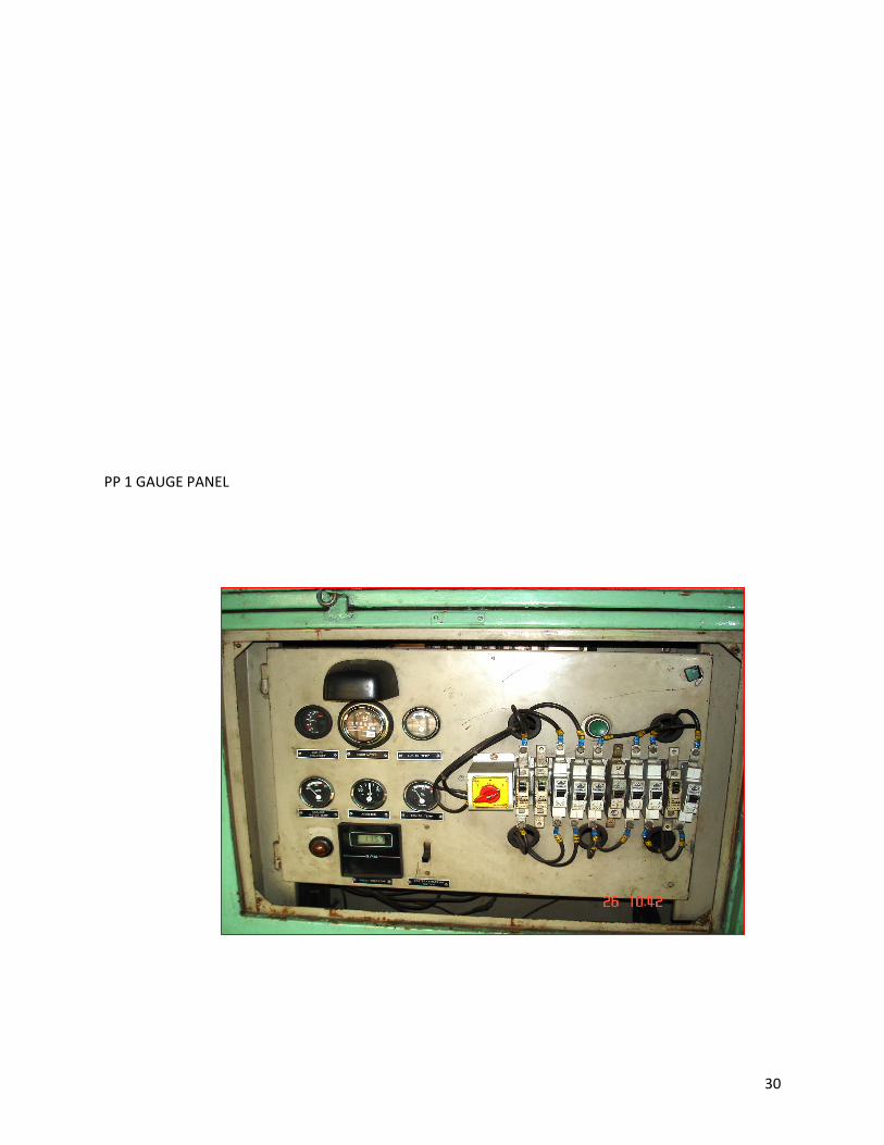
30
PP 1 GAUGE PANEL

31
VOLT METER GAUGE PANEL

32
CS 1 & CS 2

33
34

35

36

37

38


