
A NEW HYBRID MULTIAXIAL FATIGUE LIFE MODEL BASED ON CRITICAL
PLANE, CONTINUUM DAMAGE MECHANICS AND GENETIC ALGORITHM
MASOOD KAMAL
Thesis submitted in fulfilment of the requirements
for the award of the degree of
Doctor of Philosophy in Mechanical Engineering
Faculty of Mechanical Engineering
UNIVERSITI MALAYSIA PAHANG
NOVEMBER 2015
vi
ABSTRACT
Multiaxial fatigue is one of the most common failure mechanisms encountered by the
mechanical components during service life. For reliability assessment of the
components under real-life service conditions, and maintenance, the understanding of
multiaxial fatigue phenomenon is essential. Despite extensive research in this area, the
fatigue life prediction is still a challenging task. The application of analytical and
numerical methods in fatigue life analysis under real-life service conditions is becoming
more significant, given the time and costs considerations in experimental testing. This
study aims to develop a hybrid multiaxial fatigue model capable of estimating fatigue
life independent of applied loading-path-shape with the application of the most
commonly available material property. A new fatigue parameter is formulated based on
stress-strain variables identified from various fatigue life models in order to deal with
mean stress effects and non-proportional hardening. Continuum damage mechanics
approach is applied to develop damage expression as a continuously damage-
accumulative function in terms of fatigue parameter. Genetic algorithm is also applied
for the calibration of proposed model in terms of calibrated coefficients. The developed
hybrid model is calibrated using complex profiles for proportional and non-proportional
loading under in-phase and out-of-phase loading conditions. The model is validated
against the published experimental results under various loading and material conditions
including SS304, carbon steel C40, EN3B, Steel20 and Titanium alloy BT9.
Interpolation scheme for calibrated model coefficients is applied for loading cases with
same profiles and different magnitude. For in-phase and out-of-phase loading with zero
and positive mean stress the proposed model provides good correlation with
experimental data (min. 4% diff.) for C40, EN3B and Steel 20. For SS304 predicted
fatigue life from proposed model for complex profiles, calibrated with characteristic
profiles, correlates well with the experimental data with an agreeable difference
(min.6%). The results of the proposed model for Titanium alloy BT9 and steel 20 with
block loading correlates reasonably well with experimental data (min. 4-10% diff.). The
proposed model serves as path-independent fatigue life estimating tool hence can be
used with any type of loading conditions. The notion of characteristic profiles for the
calibration of the model is also coherent with the application of equivalent fatigue
loading in generating experimental data for calibration. The model is simple in
application with the use of genetic algorithm for model calibration making use of only
the material fatigue limit. Thus the proposed model is more accurate for variety of
loading and material conditions. The hybrid approach of critical plane, continuum
damage mechanics and calibration through genetic algorithm provided a strong basis for
a universally accepted multiaxial fatigue life model. Interpolation scheme based on the
multiaixality of stresses is suggested for the determination of coefficients of the model
for different loading paths. Material parameter including stress sensitivity factor for
normal or shear stress can be incorporated to improve the calibration process. The
proposed model can serve as an efficient tool for multiaxial fatigue life analysis in
academics as well as commercial applications, especially automotive and aircraft
industry, due to inherent flexibility of the model for accommodating different loading
conditions.

vii
ABSTRAK
Kelesuan berbilang paksi adalah salah satu mekanisma kegagalan biasa yang terjadi ke
atas komponen mekanikal semasa digunakan. Kefahaman yang mendalam untuk
fenomena kelesuan berbilang paksi adalah amat penting apabila pengukuran
kebolehpercayaan komponen di buat dalam keadaan pengunaan sebenar dan proses
membaikpulih. Walaupun banyak kajian telah di lakukan untuk bidang ini, kajian
jangkaan hayat kelesuan masih merupakan satu tugas yang mencabar. Penggunaan
kaedah analisis dan berangka dalam analisis ketahanan keleusuan di dalam keadaan
pengunaan sebenar menjadi lebih penting dan diberi pertimbangan masa dan kos dalam
kajian. Kajian ini bertujuan untuk membangunkan model kelesuan berbilang paksi
hibrid yang mampu menganggarkan kelesuan yang bebas daripada beban gunaan laluan-
bentuk dengan sifat bahan yang sedia ada. Parameter keletihan baru digubal berdasarkan
pembolehubah tegasan-terikan yang dikenal pasti dari pelbagai model keleusuan yang
sedia ada untuk menangani kesan-kesan tekanan yang minima dan pengerasan bukan
berkadar. Pendekatan kontinum mekanik digunakan untuk membangunkan kerosakan
terkumpul secara berterusan sahaja kerosakan dari segi parameter kelesuan. Algoritma
genetik juga digunakan untuk penentukuran model yang dicadangkan dari segi pekali-
terukur. Model hibrid yang telah di bina ditentukur menggunakan profil kompleks untuk
bebanan berkadar dan bukan berkadar di dalam dan di luar fasa benanan tersebut. Model
yang telah disahkan dengan keputusan ujikaji yang diterbitkan di bawah pelbagai
keadaan bebanan dan bahan termasuk SS304, keluli karbon C40, EN3B, Steel20 dan
Titanium aloi BT9. Sisipan skim bagi model pekali yang telah disahkan telah digunakan
untuk bebanan kes profil yang sama dan berlainan magnitud. Bagi di dalam dan di luar
fasa bebanan sifar dan positif bermaksud tekanan model cadangan memberi hubungan
yang baik dengan data ujikaji (minima kelainan 4%) untuk bahan C40, EN3B dan
Steel20. Untuk SS304 tahap kelesuan diramalkan dari model yang dicadangkan untuk
profil kompleks, ditentukan dengan ciri-ciri profil, di sahkan dengan data ujikaji dengan
perbezaan yang di persetujui (minima 6%). Keputusan untuk model yang
dicadangkan untuk bahan BT9 aloi dan Steel20 adalah di sahlkan dengan baik dengan
data ujikaji (minima kelainan 4%). Model yang dicadangkan telah digunakan sebagai
kaedah kelesuan bebas untuk membuat pengganggaran dengan mana-mana jenis
bebanan. Konsep ciri-ciri profil untuk penentukuran model ini juga koheren dengan
kelesuan bebanan setara untuk menjana data-data ujikaji penentukuran. Model yang
mudah dalam aplikasi menggunakan algoritma genetik untuk penentukuran model
menggunakan hanya had lesu bahan. Oleh itu model yang dicadangkan adalah lebih
tepat bagi pelbagai jenis pembebanan dan keadaan bahan. Pendekatan hibrid satah
kritikal, mekanik kontinum dan penentukuran melalui algoritma genetik memberikan
asas yang kukuh untuk penerimaan universal untuk kelesuan berbilang paksi. Skim
sisipan yang berdasarkan tegasan berbilang paksi dicadangkan untuk penentuan pekali
untuk model bagi bebanan yang berbeza. Parameter bahan termasuk faktor sensitiviti
tekanan biasa atau tegasan ricih boleh digunakan bersama untuk meningkatkan kuality
proses penentukuran. Model yang dicadangkan boleh dijadikan cara yang cekap untuk
menanalisa kelesuan berbilang paksi di dalam kajian akademik serta penggunaan
komersil, terutama di dalam bidang automotif dan industri pesawat, kerana model ini
memberikan keadaan fleksibiliti bagi menampung bebanan yang pelbagai.

viii
TABLE OF CONTENTS
Page
SUPERVISOR’S DECLARATION ii
STUDENT’S DECLARATION iii
DEDICATION iv
ACKNOWLEDGEMENTS v
ABSTRACT vi
ABSTRAK vii
TABLE OF CONTENTS viii
LIST OF TABLES xii
LIST OF FIGURES xiv
LIST OF SYMBOLS xvii
LIST OF ABBREVIATIONS xxii
CHAPTER 1 INTRODUCTION
1.1 Introduction 1
1.2 Research Motivations 3
1.3 Problem Statement 4
1.4 Objectives of the Study 6
1.5 Scope of the Study 7
1.6 Overview of the Thesis 8
CHAPTER 2 LITERATURE REVIEW
2.1 Introduction 9
2.2 Fatigue Life Estimation 9
2.3 Multiaxial Material Fatigue Modelling 10
2.4 Classical Multiaxial Fatigue Life Estimation Models 12
2.4.1 Stress based Models 12
2.4.2 Strain based Models 14
2.4.3 Strain Energy based Models 14
2.5 Advances in Multiaxial Fatigue Life Estimation Models 18
2.5.1 Critical Plane Models 18
ix
2.5.2 Enclosed Surface Models 24
2.5.3 Integral Type Models 26
2.5.4 Material Structure based Models 29
2.5.5 Stress Invariants based Models 30
2.5.6 Statistical Assessment Models 31
2.5.7 Plasticity Framework Models 31
2.6 Optimization Algorithm in Fatigue Analysis 33
2.7 Finite Element Analysis in Fatigue Life Estimation 37
2.8 Summary 38
CHAPTER 3 METHODOLOGY
3.1 Introduction 40
3.2 Flow Chart of the Study 40
3.3 Stress and Strain Parameters 42
3.3.1 Selection of Stress and Strain Parameters 42
3.3.2 Stress and Strain on a Plane 44
3.3.3 Stress Strain Plasticity Modelling 45
3.4 Proposed Multiaxial Fatigue Models 49
3.5 Working of Proposed Fatigue Model 52
3.6 Multi-Objective Genetic Algorithm 56
3.7 Model Calibration Method 58
3.7.1 Incremental Angle Method 61
3.7.2 Critical Plane Method 62
3.8 Development of Damage Estimation Code 64
3.9 Development of Genetic Algorithm Model 67
3.9.1 Initialization 68
3.9.2 Convergence Criteria 68
3.9.3 Determination of Calibrated Coefficients 69
3.10 Fatigue Life Estimation Procedure 70
3.11 Validation of Model 72
3.11.1 Load Cases 73
3.11.2 Materials Properties 73
3.12 Finite Element Analysis Modelling 76
3.12.1 EN3B Specimen 76
3.12.2 C40 Specimen 77
3.12.3 SS304 Specimen 78
3.12.4 Low Carbon Steel (steel 20) Specimen 80
3.12.5 Titanium alloy (BT9) specimen 81
x
3.13 Mesh Convergence of Finite Element Models 83
3.13.1 Mesh Type Selection 83
3.13.2 Identification of Mesh Size 84
3.13.3 Verification of FEA Models 87
3.14 Summary 87
CHAPTER 4 RESULTS AND DISCUSSION
4.1 Introduction 88
4.2 Comparative Analysis of Proposed Multiaxial Fatigue Models 88
4.3 Performance of Proposed Model with Different Materials and Loading
Conditions
95
4.3.1 C40 Carbon Steel with In-phase and Out of Phase Loading 95
4.3.2 EN3B Steel Alloy with In-phase and Out of Phase Loading 99
4.3.3 Low Carbon Steel (Steel 20) with Axial and Torsion Loading 103
4.3.4 Low Carbon Steel (Steel 20) with Blocks of Axial and Torsion
Loads
108
4.3.5 Stainless Steel SS304 with Complex Profiles 111
4.3.6 Titanium alloy BT9 with Combination of Axial, Shear and Out of
Phase Axial and Shear Load
116
4.4 Evaluation of Proposed Model Results With Common Multiaxial Fatigue
Models
124
4.5 Performance of Developed Critical Plane Estimation Technique 134
4.6 Summary 146
CHAPTER 5 CONCLUSIONS AND RECOMMENDATIONS
5.1 Introduction 147
5.2 Summary of Findings 147
5.2.1 Modelling of Fatigue Parameter Expressions 147
5.2.2 GA based Model Calibration 148
5.2.3 Performance Analysis 148
5.2.4 Critical Plane Estimation Method 149
5.3 Contributions of the Study 150
5.4 Recommendations for Future Work 151
REFERENCES 152
LIST OF PUBLICATIONS 166
xi
APPENDICES
A1 Incremental Angle Method for Critical Plane 168
A2 Single Parameter GA Based Critical Plane Method 172
A3 Implementation of Maximum Variance of Shear 176
A4 Extraction of Stress-Strain Quantities on Critical Plane 181
A5 Coding for Damage Estimation in Calibration Phase 184
A6 Coding for Fatigue Life Estimation 186

xii
LIST OF TABLES
Table No. Title Page
2.1 Classification of various types of fatigue analysis 11
3.1 List of stress / strain components used in fatigue models 43
3.2 Direction cosines for coordinate transformation 45
3.3 Loading and material detail used in the study 74
3.4 Profile paths for SS 304 (ε – x axis and γ – y axis) 74
3.5 Properties of materials used in the study 75
3.6 Fatigue limit of materials 76
3.7 Comparison of calculated and actual stresses in considered
specimens
87
4.1 Applied axial and shear strain load sets for SS304 specimen 89
4.2 Predicted fatigue life by Model-1 and Model-2 with respective
loading for SS304 specimen
90
4.3 Calibrated coefficients from genetic algorithm for SS304 91
4.4 No. of iterations for calibration of model using GA 91
4.5 Predicted fatigue life of C40 steel 96
4.6 Calibrated coefficients from genetic algorithm for C40 Carbon
steel
97
4.7 Calibrated coefficients from genetic algorithm for EN3B steel
alloy
100
4.8 Predicted fatigue life for EN3B steel 101
4.9 Predicted fatigue life for low carbon steel (Steel 20) 106
4.10 Calibrated coefficients from genetic algorithm for low carbon
steel (Steel 20)
106
4.11 Fatigue life for block loads with respect to each calibration for
low carbon steel (Steel 20)
109
xiii
Table No. Title Page
4.12 Fatigue life predicted for SS304 113
4.13 Specimen and loads used for calibration for Titanium Alloy BT9 118
4.14 Calibrated coefficients from genetic algorithm for Titanium Alloy
BT9
118
4.15 Fatigue life for block loads with respect to each calibration for
Titanium Alloy BT9
119
4.16 Predicted fatigue life for C40 specimen 126
4.17 Predicted fatigue life for SS304 specimen 127
4.18 Estimated locations of critical planes for SS304 specimen 128
4.19 Critical planes for C40 specimen 135
4.20 Critical planes for SS304 specimen 136
4.21 Critical plane with fatigue parameter and variance of shear stress
maximized on SS304 specimen
140
xiv
LIST OF FIGURES
Figure No. Title Page
3.1 Flow chart of the study 41
3.2 Plane location defined by angle θ and ϕ 46
3.3 Yield surface after Isotropic hardening 48
3.4 Yield surface after Kinematic hardening 49
3.5 Fatigue life estimation process for the proposed model 54
3.6 MOGA-II algorithm flow chart 58
3.7 Calibration process flow chart for proposed model 60
3.8 Incremental angle method flow chart 61
3.9 GA-based critical plane setup diagram 63
3.10 GA-based critical plane method flow chart 63
3.11 Two parameter GA-based critical plane setup diagram 64
3.12 Combined flow chart for Incremental angle and GA-based critical
plane methods
65
3.13 Process flow chart for calibration of fatigue model 66
3.14 GA workflow diagrams for calibration of fatigue model
(a) Model-1; (b) Model-2
67
3.15 Flow chart of fatigue life estimation process 71
3.16 Normal strain (x-axis) and shear strain (y-axis) loading profile
(a) Fully proportional; (b) Nearly proportional with small steps
72
3.17 Geometry detail of EN3B specimen with notch radius – 1.25 mm 77
3.18 Structural and finite element model for EN3B specimens with
loading and boundary conditions
77
3.19 Geometry detail of C40 specimen with length – 200 mm 78
3.20 Structural and finite element model for C40 specimen with loading
and boundary conditions
78
xv
Figure No. Title Page
3.21 Geometry detail of SS304 specimen 79
3.22 Structural and finite element model for SS304 specimen with
loading and boundary conditions
79
3.23 Geometry detail of low carbon steel (Steel 20) specimen 80
3.24 Structural and finite element model for low carbon steel (Steel 20)
specimen with loading and boundary conditions
80
3.25 Geometry detail of Titanium Alloy BT9 tubular specimen 81
3.26 Structural and finite element model for Titanium Alloy BT9
tubular specimen with loading and boundary conditions
82
3.27 Structural and finite element model for Alloy BT9 solid specimen
with dia. 4 mm and 19 mm gauge length specimen with loading
and boundary conditions
82
3.28 Mesh size versus calculated FEA stresses (a-e) mesh size versus
no. of nodes and elements of FEA model (f-j)
86
4.1 Applied axial and shear strain load sets for SS304 specimen 89
4.2 Predicted fatigue life (cycles) versus experimental fatigue for
SS304 specimen against various profiles and applied strain
loadings
93
4.3 Predicted versus experimental life for C40 steel with respect to
stress ratio (R) and phase difference
98
4.4 Predicted versus experimental life against applied normal stress
for EN3B steel with respect to stress ratio (R) and phase difference
102
4.5 Stress distribution, angle designation and crack locations around
notch hole
105
4.6 Predicted versus experimental fatigue life for low carbon steel
(Steel 20) with applied normal and shear stress
107
4.7 Predicted and experimental fatigue life for block loading for
carbon steel (Steel 20)
109
4.8 Predicted versus experimental life for SS304 with respect to
applied strain load, calibration load and load profile used for
calibration
114
xvi
Figure No. Title Page
4.9 Loading blocks composed of different combinations of axial,
torsion and 90° out-of-phase axial–torsion strain paths
117
4.10 Experimental and predicted fatigue life of Titanium Alloy BT9 for
block loads with different calibrations
120
4.11 Fatigue parameter variation of proposed and Fatemi-Socie model
for Titanium Alloy BT9 with respect to plane angle
122
4.12 Critical plane orientation for each block loading by proposed
model, Fatemi-Socie model and experimentally determined for
Titanium Alloy BT9
124
4.13 Resolution of normal stress for critical plan 125
4.14 Fatigue life of C40 from various models versus experimental life 130
4.15 Fatigue life of SS304 form various models versus experimental
life
131
4.16 Proposed and Fatemi-Socie parameter variations with plane angle
for SS304 and Set 2
133
4.17 Fatigue parameter estimation for C40 steel with R-1-Ph90-199.7
MPa loading case (a) with incremental angle (b) GA
137
4.18 Proposed fatigue parameter and variance of shear with plane
angles for SS304 specimen, Set 1 strains for profile Paths 1 - 13
141
xvii
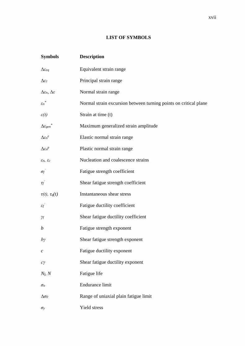
LIST OF SYMBOLS
Symbols Description
∆εeq Equivalent strain range
∆ε1 Principal strain range
∆εn, ∆ε Normal strain range
εn* Normal strain excursion between turning points on critical plane
ε(t) Strain at time (t)
∆εgen* Maximum generalized strain amplitude
∆εne Elastic normal strain range
∆εnp Plastic normal strain range
εn, εc Nucleation and coalescence strains
σf’ Fatigue strength coefficient
τf’ Shear fatigue strength coefficient
τ(t), τq(t) Instantaneous shear stress
εf’ Fatigue ductility coefficient
γf Shear fatigue ductility coefficient
b Fatigue strength exponent
bγ Shear fatigue strength exponent
c Fatigue ductility exponent
cγ Shear fatigue ductility exponent
Nf, N Fatigue life
σo Endurance limit
∆σ0 Range of uniaxial plain fatigue limit
σy Yield stress
xviii
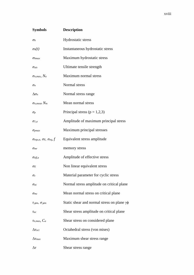
Symbols Description
σh Hydrostatic stress
σh(t) Instantaneous hydrostatic stress
σhmax Maximum hydrostatic stress
σuts Ultimate tensile strength
σn,max, Na Maximum normal stress
σn Normal stress
∆σn Normal stress range
σn,mean Nm Mean normal stress
σp Principal stress (p = 1,2,3)
σ1,a Amplitude of maximum principal stress
σpmax Maximum principal stresses
σequ,a, σE, σeq, f Equivalent stress amplitude
σmr memory stress
σeff,a Amplitude of effective stress
σE Non linear equivalent stress
σc Material parameter for cyclic stress
σac Normal stress amplitude on critical plane
σmc Mean normal stress on critical plane
τϕm, σϕm Static shear and normal stress on plane ϕ
τac Shear stress amplitude on critical plane
τn,max, Ca Shear stress on considered plane
∆τoct Octahedral stress (von mises)
∆τmax Maximum shear stress range
∆τ Shear stress range
xix
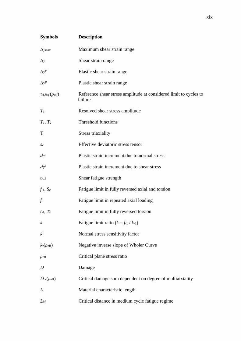
Symbols Description
∆γmax Maximum shear strain range
∆γ Shear strain range
∆γe Elastic shear strain range
∆γp Plastic shear strain range
τA,Ref (ρeff) Reference shear stress amplitude at considered limit to cycles to
failure
Ta Resolved shear stress amplitude
T1, T2 Threshold functions
T Stress triaxiality
se Effective deviatoric stress tensor
dεp Plastic strain increment due to normal stress
dγp Plastic strain increment due to shear stress
tA,B Shear fatigue strength
f-1, Se Fatigue limit in fully reversed axial and torsion
f0 Fatigue limit in repeated axial loading
t-1, Te Fatigue limit in fully reversed torsion
k Fatigue limit ratio (k = f-1 / k-1)
k’ Normal stress sensitivity factor
kτ(ρeff) Negative inverse slope of Wholer Curve
ρeff Critical plane stress ratio
D Damage
Dcr(ρeff) Critical damage sum dependent on degree of multiaixiality
L Material characteristic length
LM Critical distance in medium cycle fatigue regime
xx
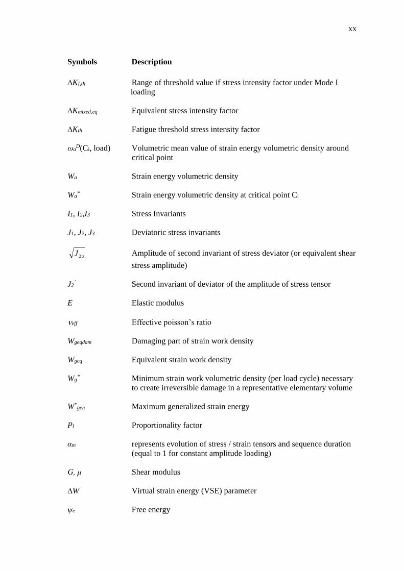
Symbols Description
∆KI,th Range of threshold value if stress intensity factor under Mode I
loading
∆Kmixed,eq Equivalent stress intensity factor
∆Kth Fatigue threshold stress intensity factor
ωaD(Ci, load) Volumetric mean value of strain energy volumetric density around
critical point
Wa Strain energy volumetric density
Wa* Strain energy volumetric density at critical point Ci
I1, I2,I3 Stress Invariants
J1, J2, J3 Deviatoric stress invariants
aJ 2 Amplitude of second invariant of stress deviator (or equivalent shear
stress amplitude)
J2’ Second invariant of deviator of the amplitude of stress tensor
E Elastic modulus
eff Effective poisson’s ratio
Wgeqdam Damaging part of strain work density
Wgeq Equivalent strain work density
Wg* Minimum strain work volumetric density (per load cycle) necessary
to create irreversible damage in a representative elementary volume
W*gen Maximum generalized strain energy
Pl Proportionality factor
αm represents evolution of stress / strain tensors and sequence duration
(equal to 1 for constant amplitude loading)
G, μ Shear modulus
∆W Virtual strain energy (VSE) parameter
ψe Free energy
xxi
Symbols Description
λae (a=1,2,3) Eigen values of elastic finger tensor
kB Bulk modulus
η(t) void nucleation at time ‘t’
KIC Critical stress intensity factor
fNf Normal stress at Nf cycles
tNf Shear stress at Nf cycles
ai, 1-5 Amplitude of deviatoric stresses
a1, a2 Half-length of sides of rectangular hull loading path
l, m, n Directional cosines of vector normal to plane
ϕ, θ, ψ Angle locating material plane
χ Angle between major axis and resolved shear stress
V*(Ci) Volume at critical point
d Length scale parameter
αd, αp Damage and plastic internal variables
α’ Slip system index
dD(α) Damage parameter increment on slip system (α)
dY(α) Plastic strains energy increment on slip system (α)
G’ Notch gradient correction factor
k1, k2, kH Loading related parameter
t time
a, b, m, n, A, B, Material parameters / model constants
S, Ccoeff, σc, m’
δ’, d1, d2, a0 – a3
σ0, γ1, γ2, γ3’, ηNf,
ac, bc, α, β, γ, δ, k,
f, a,, b,, c, m, n, λ
xxii
LIST OF ABBREVIATIONS
ANN Artificial Neural Network
APDL Ansys Parametric Design Language
CARLOS Car Loading Standard
CPU Central Processing Unit
DASA Differential Ant Stigmergy Algorithm
EFL Equivalent Fatigue Loads
FE Finite Element
FEA Finite Element Analysis
FEM Finite Element Method
GA Genetic Algorithm
MOGA-II Multi Objective Genetic Algorithm II
SAE Society of Automotive Engineers
VB Visual Basic
CHAPTER 1
INTRODUCTION
1.1 INTRODUCTION
Fatigue is a common phenomenon during the service life of machines,
equipment, vehicles, buildings, aircraft and several other structures subjected to time
variable combined tension, bending and torsion load. These complex cyclic loadings are
defined as multiaxial loadings, where the principal stresses rotate and change their
magnitude non-proportionally during loading (Suman, 2013). The fatigue is classified
on the basis of the state of stress and the load level. On the basis of the stress state,
fatigue is divided into the two categories of uniaxial and multiaxial fatigue (Milella,
2013). For uniaxial fatigue, the cyclic stresses do not change direction, such as in the
case of axial and bending loadings. In the case of multiaxial fatigue, the time-varying
loads in the cyclic stress change direction and act as combined axial and torsion out-of-
phase loading. Moreover, based on the level of loading, fatigue is classified as either
low-cycle fatigue (LCF) or high-cycle fatigue (HCF). For LCF, the amplitude of loading
is high enough that the component fails in less than approximately 103–104 cycles.
However, fatigue life greater than 104-106 cycles is referred to as HCF due to the low
magnitude of the applied loading (Manson and Halford, 2006). During HCF,
deformations in components are mainly elastic, but for LCF deformations can be both
elastic and plastic. As multiaxial fatigue is a time-dependent phenomenon, the
modelling of physical conditions with mathematical models to predict the damage is
certainly a challenging task (Sun et al., 2013). Unfortunately, the combination of
multiaxial loading paths and complex geometries of components cannot be avoided in
real-world scenarios and durability test experiments in most situations are not feasible
due to time and cost considerations (Ince, 2013). Therefore, analytical and numerical

2
methods are an essential approach to perform fatigue and durability analysis in
designing mechanical components.
A number of studies for the estimation of multiaxial fatigue life have been
performed by researchers over the past 60 years. Various innovative techniques and
approaches have been proposed during this period to address the complex phenomenon
of multiaxial fatigue (Kenmeugne et al., 2012; Macha and Niesłony, 2012). These
approaches include continuum damage mechanics (CDM) (Khandelwal and El-Tawil,
2014), modified rainflow cycle counting (Meggiolaro and de Castro, 2012),
optimization algorithms (Klemenc and Fajdiga, 2013) and critical-plane based fatigue
life estimation models (Ince and Glinka, 2014). CDM is based on the framework of the
thermodynamics of an irreversible process with damage as an irreversible and
continuously increasing function (Chaboche, 1998a, b; Ottosen et al., 2008; Khandelwal
and El-Tawil, 2014). Cycle counting methods are used to identify individual cycles
from a variable loading history. Fatigue life is then estimated for the cycles identified
from the fatigue data and curves obtained with simple constant amplitude load cycles
(Manson and Halford, 2006; Meggiolaro and de Castro, 2012), however with the loss of
the sequence of loading information (Anes et al., 2014).
Optimization is the act of obtaining the best solution under given circumstances
(Pinto, 2007), and in the last decade evolutionary optimization algorithms have gained
popularity in formulating fatigue life estimation methodologies (Krishnapillai and
Jones, 2009; Brighenti and Carpinteri, 2012; Klemenc and Fajdiga, 2013). Critical plane
models are based on experimental observations that cracks nucleate and grow on
specific planes known as critical planes, and these models relate fatigue damage to
stresses and strains on these planes. These models can predict fatigue life as well as the
orientation of the cracks (Stephens et al., 2000). With all these efforts, the need to fully
understand the multiaxial behaviour of different materials under various loading
conditions is a special focus of this research. In spite of the importance of
understanding multiaxial fatigue behaviour, limited literature exists on the subject due
to the inherent complexities in studying this topic (Shamsaei, 2010; Gates and Fatemi,
2014).

3
Considering the effectiveness of the CDM and critical plane methods, a hybrid
approach with the flexibility of evolutionary optimization algorithms has been proposed
to estimate the multiaxial fatigue life. The proposed methodology does not require cycle
counting and thus avoids the loss of loading sequence data by treating the damage as a
continuously increasing function as the load time history advances. The proposed
method incorporates the benefits of the critical plane estimation to predict the fatigue
life as well as the direction of crack growth. Multi-objective optimization based on
genetic algorithm (GA) has been used to calibrate the model coefficients as well as to
predict the critical plane using more than one critical plane determination criterion.
1.2 RESEARCH MOTIVATIONS
Most components in real-life scenarios have a multiaxial state of stress and are
subjected to random loading conditions. Therefore, the study of multiaxial fatigue under
complex loading conditions is of great practical significance (Reis et al., 2003; Rahman
et al., 2009; Marquis, 2010; Gates et al., 2014). Models for fatigue life prediction in the
case of uniaxial loadings are well established; however, for multiaxial as well as random
amplitude loading conditions, research is still in progress. Very few methods are
proposed in the literature addressing fatigue life estimation for non-proportional
multiaxial loading (Shamsaei, 2010; Gates and Fatemi, 2014). However, while many
fatigue parameters to address multiaxial fatigue have been proposed during recent
decades, due to the challenging nature of the problem, a universally accepted model
which can be used in various loading and material conditions is still needed for reliable
multiaxial fatigue life estimation (Ganjidoust and Shariyat, 2009; Fatemi and Shamsaei,
2011; Gómez et al., 2011; Ince, 2013; Ince and Glinka, 2014). The requirement to
produce highly reliable products, with a cost-effective design process in terms of
prototyping and testing is always the prime concern of design engineers (Ince, 2012).
Testing and analysis are two essentials tools for design against fatigue failure. In order
to reduce the design cost, it is essential to reduce the experimental testing and
prototyping cost (Shamsaei, 2010). This goal can be achieved by replacing experimental
testing with accurate analysis, especially in the early design stages. In order to evaluate
fatigue life accurately, a technique is required which is capable of handling various
4
loading and material conditions and is adaptable for both academic and industrial
applications.
1.3 PROBLEM STATEMENT
Most machine components are subjected to combined cyclic tension, bending
and torsional loads during their service life. In addition, many machine components
have complex geometries as per design requirements, which can cause stress
concentration areas (Acevedoa and Nussbaumer, 2009). With multiaxial loads, complex
stress–strain states occur around stress concentration points and can cause fatigue
failure without any apparent large-scale plastic deformations (Schijve, 2009; Schmid et
al., 2013). To address this issue, various models have been proposed for multiaxial
fatigue life estimation. However, most of these work accurately only for certain material
and loading conditions (Marquis, 2010; Gómez et al., 2011; Ince and Glinka, 2014). In
addition, as experimental testing for fatigue life becomes unfeasible in most situations,
especially in the early design stages, the requirement for a fatigue life model that can
serve as a general purpose model as well as for various materials and loading conditions
is therefore indispensable to bring down the cost of product design (Ince, 2012; Suman,
2013).
While the development of uniaxial fatigue models is at a quite mature stage, the
modelling of multiaxial fatigue damage is still an active area of research (Liu, 2006;
Habtour et al., 2014). Multiaxial fatigue modelling can generally be classified in three
major categories: equivalent stress/strain-based, energy-based and critical plane-based.
Equivalent stress/strain theories use the von Mises or Tresca failure criterion for an
equivalent representation of stress and strain. These criteria cannot distinguish between
proportional and non-proportional loading. Energy-based theories determine the strain
energy within a material during the loading cycle and compare it with a critical value.
Since energy is a scalar quantity, these criteria do not provide physical interpretations of
the process by which fatigue cracks initiate and propagate along certain directions or
planes in the material (Suman, 2013). The third theory was initially proposed by Findley
(1959), based on orientation planes having cracks in the material, and is thus named
critical plane methodology. This technique has gained widespread acceptance and many

5
improvements have been proposed by researchers, including Brown and Miller (1973),
Fatemi and Socie (1988), Dang Van (1993), Lazzarin and Susmel (2003) and Susmel
(2010), to name a few. Thus the critical plane concept is a better option to use as the
basis of new fatigue life models.
Real-life loading conditions are variable in amplitude, while most multiaxial
fatigue life models are formulated on the basis of constant amplitude loading (Suman,
2013). In order to estimate the fatigue life for variable amplitude loading, cycle
counting methods are applied to compare the effect of variable amplitude loading
histories to fatigue data obtained with simple constant amplitude load cycles (Stephens
et al., 2000). Fatigue life is estimated for each of the counted constant amplitude cycle
set and cumulative damage is determined with respect to the number of cycles counted
for each magnitude determined from the variable loading history. The main drawback of
the cycle counting method is the loss of the sequence of loading data, which can lead to
ignoring any effect it might have on fatigue life (Gao et al., 2014). The concept of
continuum damage mechanics deals with fatigue damage as a constantly increasing
function, where the damage is accumulated as the loading history progresses with time
(Bobyr et al., 2014). The essential feature of CDM theory is that it is formulated by
means of incremental relations and not changes per cycle, so it contains in itself the
damage accumulation; thus the cycle counting method is no longer required and the loss
of data can be avoided (Ottosen et al., 2008).
The application of evolutionary optimization algorithms in fatigue life
estimation is a relatively new research domain (Zhou et al., 2012). Approaches like
genetic algorithms (GA) and artificial neural networking (ANN) are employed to
estimate the model parameters. Complex interrelationships can be established between
physical and theoretical correlations with experimental observations (Bukkapatnam and
Sadananda, 2005; Roux et al., 2013). These approaches can be termed as material-
independent data-driven methods correlating input and output parameters and
establishing the relationship between them. Thus, with an adequate amount of data,
these models can be used with any material and loading configurations (Vassilopoulos
et al., 2008; Brighenti and Carpinteri, 2012; Klemenc and Fajdiga, 2013).
6
This research aims at finding a hybrid approach incorporating the multi-
objective optimization algorithm with a critical plane-based fatigue estimation model.
The model should be independent of the loading path shape and work with various
material conditions. Implementation of the model should be easy enough to make it
easily adaptable by industry. To achieve this, a methodology is proposed to integrate the
benefits of the concepts which have been successfully applied before for various
specific loading and material conditions but were not suitable as a general purpose or
universal approach. The first step is the proposal of a new fatigue parameter expression
based on the stress–strain parameters identified from the earlier published fatigue
models, which are used to handle the effects of mean stress, high-cycle and low-cycle
fatigue and non-proportional hardening. The proposed model is developed on the basis
of the critical plane method, where the fatigue parameter is maximized as a whole to
locate the critical plane. Secondly the calibration methodology is proposed to estimate
the coefficients of the fatigue model expressions with the application of optimization
algorithms by using the known experimental data about fatigue life and fatigue limit.
This formulation is proposed on the assumption that, as per the continuum damage
mechanics approach, damage is a continuously increasing function until unity or failure.
This approach will allow the damage estimation to be independent of the loading path,
as damage will follow the loading path as it progresses and not depend on the cycle
counting methods. In the case of loading blocks or constant amplitude cycles, the
Palmgren–Miner linear damage rule will be applied to determine the number of cycles
or blocks of loading to failure.
1.4 OBJECTIVES OF THE STUDY
The objectives of the study are summarized as follows:
i. To develop a multiaxial fatigue life estimation model based on the continuum
damage mechanics approach and critical plane method.
ii. To determine calibrated coefficients for the proposed model utilizing
optimization algorithms.


