A probabilistic ontology-based platform for self-learning
context-aware healthcare applications
Femke Ongenaea,∗, Maxim Claeysa, Thomas Duponta, Wannes Kerckhovea,Piet Verhoeveb, Tom Dhaenea, Filip De Turcka
aDepartment of Information Technology (INTEC), Ghent University - iMinds, GastonCrommenlaan 8 bus 201, B-9050 Ghent, Belgium
biMinds VZW, Gaston Crommenlaan 8 bus 102, B-9050 Ghent, Belgium
Abstract
Context-aware platforms consist of dynamic algorithms that take the context
information into account to adapt the behavior of the applications. The
relevant context information is modeled in a context model. Recently, a trend
has emerged towards capturing the context in an ontology, which formally
models the concepts within a certain domain, their relations and properties.
Although much research has been done on the subject, the adoption of
context-aware services in healthcare is lagging behind what could be ex-
pected. The main complaint made by users is that they had to significantly
alter workflow patterns to accommodate the system. When new technology is
introduced, the behavior of the users changes to adapt to it. Moreover, small
differences in user requirements often occur between different environments
where the application is deployed. However, it is difficult to foresee these
∗Corresponding author: Tel.: +32 9 331 49 38, Fax: +32 9 331 48 99Email addresses: [email protected] (Femke Ongenae),
[email protected] (Maxim Claeys), [email protected](Thomas Dupont), [email protected] (Wannes Kerckhove),[email protected] (Piet Verhoeve), [email protected] (TomDhaene), [email protected] (Filip De Turck)
Preprint submitted to Expert Systems with Applications September 12, 2013
changes in workflow patterns and requirements at development time. Con-
sequently, the context-aware applications are not tuned towards the needs
of the users and they are required to change their behavior to accommodate
the technology instead of the other way around.
To tackle this issue, a self-learning, probabilistic, ontology-based frame-
work is proposed, which allows context-aware applications to adapt their
behavior at run-time. It exploits the context information gathered in the
ontology to mine for trends and patterns in the behavior of the users. These
trends are then prioritized and filtered by associating probabilities, which ex-
press their reliability. This new knowledge and their associated probabilities
are then integrated into the context model and dynamic algorithms. Finally,
the probabilities are in- or decreased, according to context and behavioral
information gathered about the usage of the learned information.
A use case is presented to illustrate the applicability of the framework,
namely mining the reasons for patients’ nurse call light use to automatically
launch calls. Detecting Systemic Inflammatory Response Syndrome (SIRS)
as a reason for nurse calls is used as a realistic scenario to evaluate the
correctness and performance of the proposed framework. It is shown that
correct results are achieved when the dataset contains at least 1,000 instances
and the amount of noise is lower than 5%. The execution time and memory
usage are also negligible for a realistic dataset, i.e., below 100 ms and 10 MB.
Keywords:
Context-aware, Self-learning, Ontology, Probability, eHealth, Nurse call
system
2
1. Introduction1
Computerized tools, health monitoring devices and sensors are being ac-2
tively adopted in modern healthcare settings, especially to support adminis-3
trative tasks, data management and patient monitoring (Orwat et al., 2008;4
Colpaert et al., 2009). Today, caregivers are directly faced with these tech-5
nologies, which increases the complexity of their daily activities (Tentori6
et al., 2009). The caregiver has to use several devices to manually consult,7
insert and combine data, even when carrying out a single task. This is very8
time-consuming. Due to this inadequate integration of the technology, as well9
as the large amount of data being generated by the devices and the heavy10
workload of staff members, it is not rare for important events to be missed,11
e.g., early indications of worsening condition of a patient. To resolve this12
issue, context-aware techniques are often proposed to automatically exploit13
the medical information available to improve continuous care and personalize14
healthcare (Burgelman and Punie, 2006).15
Although much research has been done on the subject, the adoption of16
context-aware services is lagging behind what could be expected. Most of17
the projects are prototypes and real applications are still difficult to find.18
Whereas the healthcare industry is quick to exploit the latest medical technol-19
ogy, they are reluctant adopters of modern health information systems (Chin,20
2004). Half of all computer-based information systems fail due to user resis-21
tance and staff interference (Anderston and Aydin, 1997). The main com-22
plaint made against mobile, context-aware systems is that users had to sig-23
nificantly alter workflow patterns to accommodate the system (Jahnke et al.,24
2004). This is due to inadequate techniques for personalization of the ser-25
3
vices, a lack of focus on the soft aspects of interaction, e.g., automated and26
personalized alerts, and the lack of tackling problems such as the need of the27
users for control (Criel and Claeys, 2008).28
The context-aware platforms use dynamic algorithms, which take the con-29
text information into account, to adapt the behavior of the applications ac-30
cording to the context and offer personalized services to the users. However,31
these algorithms are defined at development time. When new technology32
is introduced, the behavior of the users changes to adapt to it. Moreover,33
different environments in which the application is deployed, e.g., different34
nursing units or hospital departments, might have slightly different require-35
ments pertaining to how the context information is taken into account. It is36
difficult to foresee these changes in behavior and small nuances in workflows37
at development time. This means that the context model might be incom-38
plete or the algorithms of the applications built on it may no longer apply.39
As the applications do not adapt to the requirements and workflow patterns40
of the users, they feel less in control of the technology and have to adapt their41
behavior to accommodate the technology instead of the other way around.42
To tackle this issue, this paper proposes a self-learning framework, which43
allows the context-aware applications to adapt their behavior at run-time to44
accommodate the changing requirements of the users. The proposed frame-45
work consist of the following techniques. First, an ontology-based context46
model with accompanying rule-based context-aware algorithms is used to47
capture the behavior of the user and the context in which it is exhibited.48
This captured information is then filtered, cleaned and structured so that it49
can be used as input for data mining techniques. The results of these data50
4
mining techniques are then prioritized and filtered by associating probabil-51
ities with the obtained results expressing how reliable or accurate they are.52
These results and their associated probabilities are then integrated into the53
context model and dynamic algorithms. These probabilities clarify to the54
stakeholders that this new knowledge has not been confirmed by rigorous55
evaluation. Finally, the probabilities are adapted, i.e., in- or decreased, ac-56
cording to context and behavioral information gathered about the usage of57
the learned information.58
The remainder of this article is organized as follows. In Section 2 the59
relevant related work is discussed and our contribution is highlighted. Sec-60
tion 3 presents the architecture of the proposed probabilistic ontology-based61
framework for self-learning context-aware healthcare applications. Section 462
discusses the generic implementation of the framework, i.e., the classes that63
can be extended to implement the specific use cases. The implementation64
of a specific use case, namely mining the reasons for patients’ call light use65
to automatically launch calls, is presented in Section 5. Finally, the main66
conclusions of this research are highlighted and the future work is discussed67
in Section 6.68
2. Related work69
2.1. Context-aware systems70
Dey and Abowd (2000) refer to context as “any information that can be71
used to characterize the situation of entities (i.e., whether a person, place or72
object) that are considered relevant to the interaction between a user and an73
application, including the user and the application themselves”. A system74
5
may be labeled as “context-aware” if it can acquire, interpret and use context75
information to adapt its behavior to the current context in use (Byun and76
Cheverst, 2004). A number of generic context platforms have been developed77
to relieve application developers from the aggregation and abstraction of con-78
text information and the derivation of high-level contexts (Hong et al., 2009a;79
Baldauf et al., 2007; Xue and Pung, 2012; Yilmaz and Erdur, 2012). Unor-80
ganized, unprocessed raw data can be voluminous, but has no meaning on81
itself as it has no relationships or context. Information is data that has been82
given meaning by defining relational connections. The proposed platforms83
employ several techniques to model this context information, i.e., key-value,84
markup scheme, graphical, object-oriented, logic-based and ontology-based85
models (Strang and Linnhoff-Popien, 2004). A notable trend is emerging to-86
wards ontology-based context-aware platforms (Gu et al., 2005; Chen, 2004;87
Santos et al., 2007; Roman et al., 2002).88
To write the dynamic algorithms, which take the context information89
captured in the ontology into account to achieve personalized and context-90
aware applications, two approaches are commonly used, namely rules or ma-91
chine learning techniques (Tsang and Clarke, 2008). Rules are manually con-92
structed at development time and thus require developers to foresee all pos-93
sible situations that can occur at runtime and define the appropriate corre-94
sponding actions. Rules are difficult to modify, maintain and scale (Prentzas95
and Hatzilygeroudis, 2007). Machine learning techniques, e.g., Bayesian net-96
works and neural networks, are also trained at development time. Bayesian97
networks suffer from similar maintenance and scalability problems as the rule-98
based approach and acquiring accurate probabilities is a tedious job (Russell99
6
and Norvig, 2003). Neural Networks require a lot of processing power and100
have consequently only been sparsely applied in context-aware applications.101
Their black-box nature also makes it difficult to gain insight into relations102
between context and actions, increasing the fear of technology and loss of103
control from the users. Consequently, with each of these approaches, the104
context-aware system is only able to cope with a fixed set of context changes105
that were taken into accounted during the design of the system.106
As mentioned previously, run-time adaptation of the dynamic algorithms107
is needed to adapt to changing behavior of the stakeholders and to truly offer108
personalized services tuned to the work practices of the specific environment109
where the application is deployed. A couple of context-aware systems exist110
that try to tackle this problem by mining historical information (Tsang and111
Clarke, 2008; Baralis et al., 2011; Strobbe et al., 2012a; Hong et al., 2009b).112
However, most of the research focusses on the development of data mining113
techniques, which can be used to learn the patterns and requirements, or use114
a black-box approach. Litte research has been done on the development of a115
complete framework for self-learning, context-aware applications and on how116
the learned knowledge should be integrated in an ontology-based platform.117
2.2. Context-aware systems in healthcare118
The use of context and context-awareness in healthcare is an active re-119
search area (Bricon-Souf and Newman, 2007; Varshney, 2009). First, there120
is a large amount of available information, specific healthcare situations and121
related tasks, which create a potentential for cognitive overload amongst the122
caregivers. Second, the patients, healthcare professionals and some equip-123
ment are fairly mobile, which requires accurate localization and adaptation124
7
of the healthcare services to the environment. Third, the financial and human125
resources are limited. This implies a need to cut cost while improving the126
quality of service to an increased number of people. Context-aware and per-127
vasive prototypes have been developed for a number of hospital (Bardram,128
2004; Skov and Hoegh, 2006; Mitchell et al., 2000; Stanford, 2003; Munoz129
et al., 2003) and homecare & residential care (Fishkin et al., 2003; Floerke-130
meier and Siegemund, 2003; Korhonen et al., 2003; de Toledo et al., 2006;131
Hu et al., 2010; Mihailidis et al., 2003; Suzuki and Doi, 2001; Jansen and132
Deklerck, 2006) use cases. Examples of context-aware healthcare systems133
based on ontologies can also be found in literature (Fook et al., 2006; Zhang134
et al., 2005; Paganelli and Giuli, 2011; Ongenae et al., 2011d).135
2.3. eHealth ontologies136
An ontology (Gruber, 1993) is a semantic model that formally describes137
the concepts in a certain domain, their relationships and attributes. In this138
way, an ontology encourages re-use and integration. By managing the data139
about the current context in an ontology, intelligent algorithms that take ad-140
vantage of this information to optimize and personalize the context-aware141
applications, can more easily be defined. The Web Ontology Language142
(OWL) (McGuinness and Harmelen, 2004) is the leading language for en-143
coding these ontologies. Because of the foundation of OWL in Description144
Logics (DLs) (Baader et al., 2003), which are a family of logics that are de-145
cidable fragments of first-order logic, the models and description of data in146
these models can be formally proved. It can also be used to detect inconsis-147
tencies in the model as well as infer new information out of the correlation of148
this data. This proofing and classification process is referred to as Reason-149
8
ing. Reasoners are implemented as generic software-modules, independent150
of the domain-specific problem. Ontologies thus effectively separate the do-151
main knowledge, which can be re-used across different applications, from the152
application logic, which can be written as rules on top of the ontology.153
The definition and use of ontologies in the medical domain is an ac-154
tive research field, as it has been recognized that ontology-based systems155
can be used to improve the management of complex health systems (Valls156
et al., 2010). Most of the developed ontologies focus on biomedical research157
and are mainly employed to clearly define medical terminology (Ongenae158
et al., 2011b), e.g., Galen Common Reference Model (Rector et al., 2003),159
the Foundational Model of Anatomy Ontology (FMA) (Rosse and Jr, 2008)160
or the Gene Ontology (Blake and Harris, 2008). Little work has been done161
on developing high-level ontologies, which can be used to model context162
information and knowledge utilized across the various continuous care set-163
tings (Ongenae et al., 2011a). However, ontologies have been developed for164
specific subdomains of continuous care, e.g., ontologies for structuring organi-165
zation knowledge in homecare assistance (Valls et al., 2010), representing the166
context of the activity in which the user is engaged (Rodrıguez et al., 2011)167
and modeling chronic disease management in homecare settings (Paganelli168
and Giuli, 2011).169
2.4. Our contribution170
In this paper, we propose a self-learning and probabilistic framework171
to adapt the behavior of ontology-based, context-aware applications to the172
changing requirements of the users and their workflow patterns. To our173
knowledge, little previous research has been done on how discovered trends174
9
and patterns can be integrated into ontology-based platforms without making175
the existing model inconsistent. To tackle this issue, we use a probabilistic176
approach, which conveys the reliability of the learned knowledge to the users177
and ensures the compatibility with existing knowledge in the context model.178
Moreover, the existing research on self-learning, context-aware applications179
concentrates on exploring data mining techniques, which can be used to dis-180
cover the trends and patterns. Our research focuses on the development181
of a complete framework to enable self-learning, context-aware healthcare182
applications.183
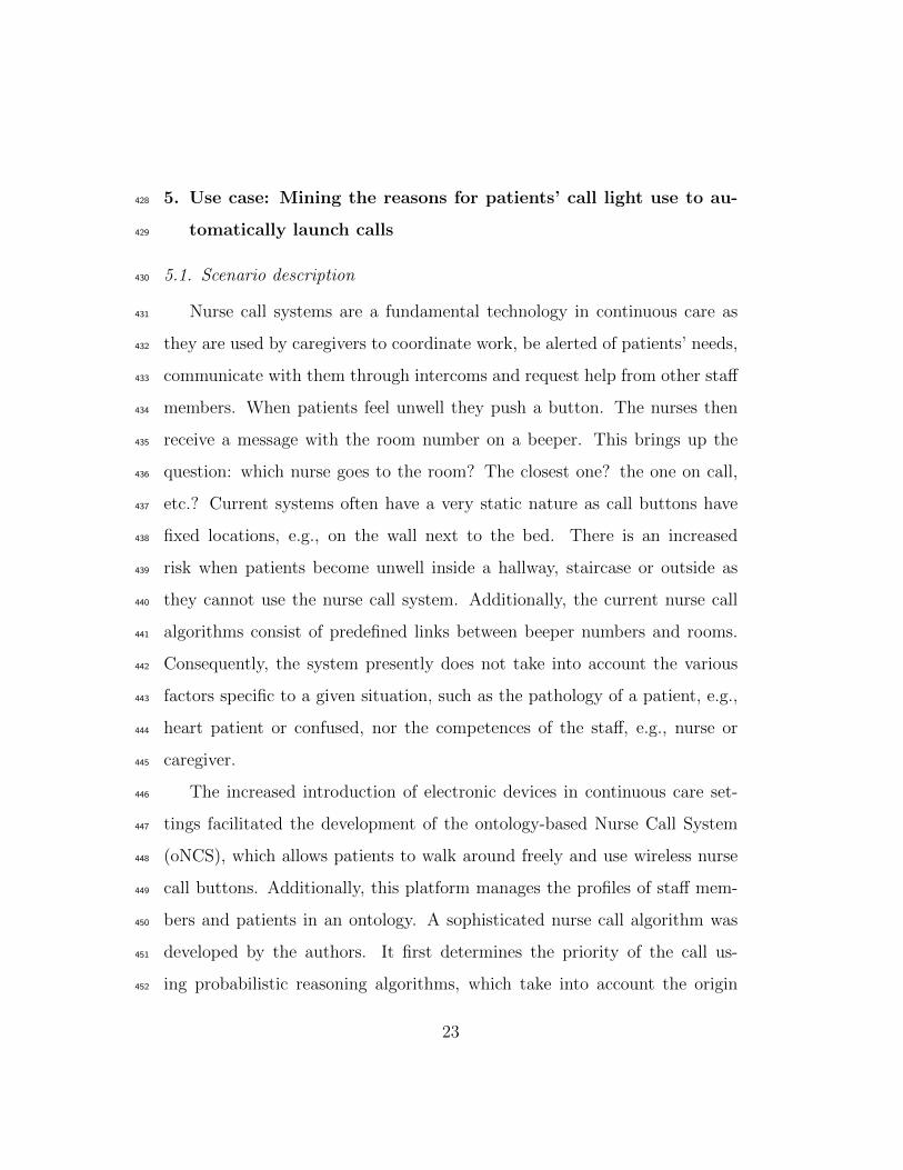
3. Architecture of the self-learning, context-aware framework184
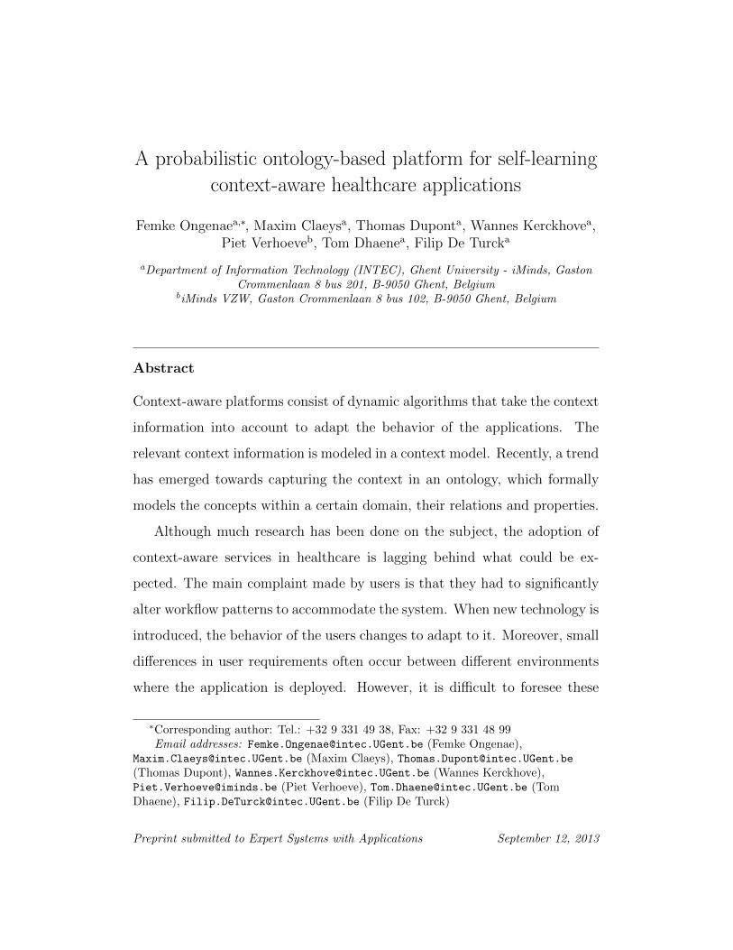
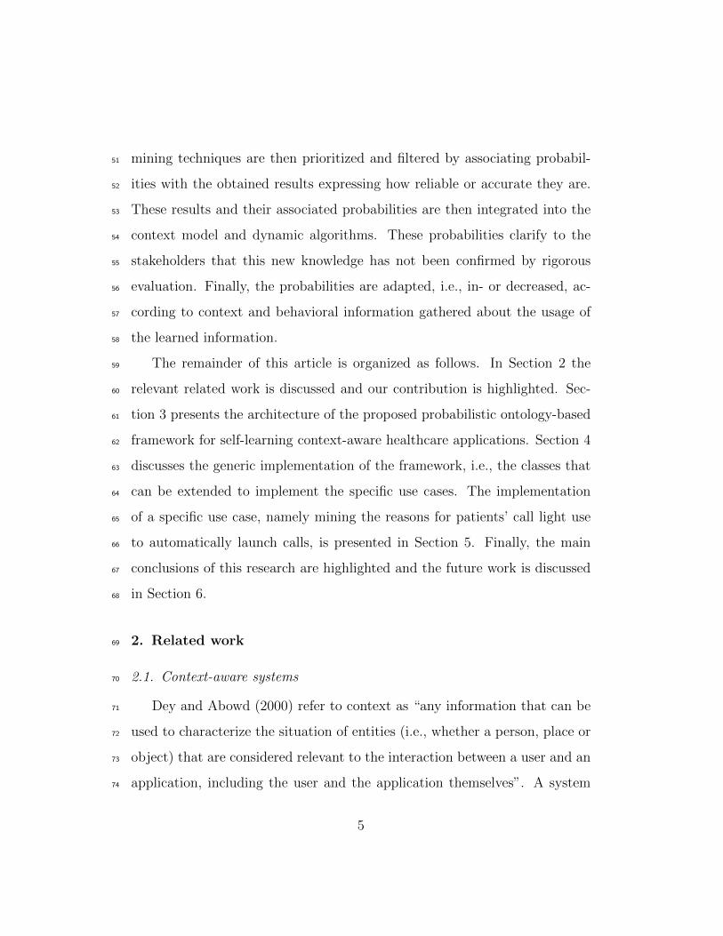
The general architecture of the proposed self-learning, context-aware frame-185
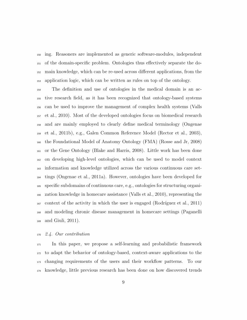
work is visualized in Figure 1. The following subsections discuss the different186
components and modules of this framework in more detail.187
3.1. Context-aware platform188
The general architecture of a context-aware, ontology-based platform can189
be split up into five layers. The Device Layer includes all the devices and190
the software on those devices that deliver context information. The modern191
healthcare settings contains a plethora of computerized medical equipment192
to convey the condition of a patient, e.g., monitoring equipment, electronic193
patient records and laboratory results stored in a database, and support the194
caregivers in their daily activities, e.g., nurse call systems and task manage-195
ment and planning tools.196
The Context Provider Layer takes care of the acquisition of specific con-197
text information, e.g., location or presence information, and translates it to198
10
Context-Aware Platform
Knowledge base
Medical
OntologiesContext-
Aware
Ontologies
Probabilistic
Domain
Ontologies
Learning
Ontology
Rules
Semantic Reasoning Layer
Context Provider Layer
Application Developers
Reasoning
Description
Logic (DL)
Reasoner
Probabilistic
Reasoner
Rule-based
Reasoning
Sensors e.g. light
sensor or
temperature sensor
RFID Equipment
e.g. PDA or nurse
call buttons
Databases
Location Presence Time Environment Person ...
Knowledge Query Layer
Location Presence Time Environment Person ...
Change status equipment
e.g. light or radiator
Alerting e.g. PDA,
displays or beepers
Intelligent furniture
e.g. bed or chair
Learning Engine
Da
ta C
olle
ctio
n M
od
ule
Inp
ut C
on
ve
rto
r
Integration
Module
Pre-Processor
Remove
outliers
Scale
Interpolation
Feature
Selection
...
Configuration
module
Monitoring
Algorithms
Stakeholders
Device Layer
Application Layer
Pe
rsis
ten
ce
La
ye
r
Data Mining
Decision Tree
Classification
Rules
Bayesian
Network
Clustering
Post-Processor
Rule
Extractor
Threshold
Extractor
...
...
Decision Module
Filter
Algorithms
Probabilistic
Relevance
Algorithms
Learning pipeline
Figure 1: General architecture of the self-learning, context-aware framework
ontology instances. These ontology instances are then added to the Knowl-199
edge Base in the Semantic Reasoning Layer. This Knowledge Base aggre-200
gates all the relevant context information into a formal context model, i.e.,201
an ontology. Existing Medical and Context-Aware Ontologies are integrated202
into the platform and extended with Domain Ontologies which model the203
information specific to a particular healthcare setting, e.g., the specific roles204
and competences of the caregivers and how they map on each other, the205
available monitoring equipment and their threshold values and specific tasks206
that need to be performed. These Domain Ontologies can also contain prob-207
abilistic information, e.g., a call made by patient with a heart disease has208
25% chance of being urgent.209
Reasoning components are then used to derive new, high-level knowledge210
11
from the information aggregated in the Knowledge Base. Due to the foun-211
dation of ontologies in Description Logics (DL), the models can be formally212
proofed by using a DL Reasoner. This DL Reasoner is used to detect incon-213
sistencies in the model as well as infer new information from the correlation of214
the data. For example, a concept Fever is created in the ontology, which au-215
tomatically detects patients with a temperature above 38 ◦C. More complex216
logic is expressed by defining Rules on top of this ontology and performing217
Rule-based Reasoning.218
The Knowledge Query Layer facilitates the retrieval of context informa-219
tion such that it can be used by the different applications and services. The220
Application Layer includes all the devices and the software on those devices221
that use the (derived) context information to adapt their behavior.222
Finally, the Persistence Layer ensures the persistence of context informa-223
tion. Static contextual information about users, devices and the environment224
can be easily obtained from these databases. More importantly, the Persis-225
tence Layer can also be used to store more dynamic information, such as226
previous locations of caregivers and patients or actions taken by the users.227
The Semantic Reasoning and Persistence Layers are the most important228
layers to facilitate a self-learning Context-Aware Platform. As the Knowledge229
Base integrates all the context information, it gives insight into the behavior230
and changing requirements of the users. All the collected context information231
and the knowledge derived from it is then persisted in the databases from232
the Persistence Layer. This lets the Learning Engine exploit this history of233
context information to derive trends and patterns and adapt the information234
in the ontology and accompanying rules accordingly.235
12
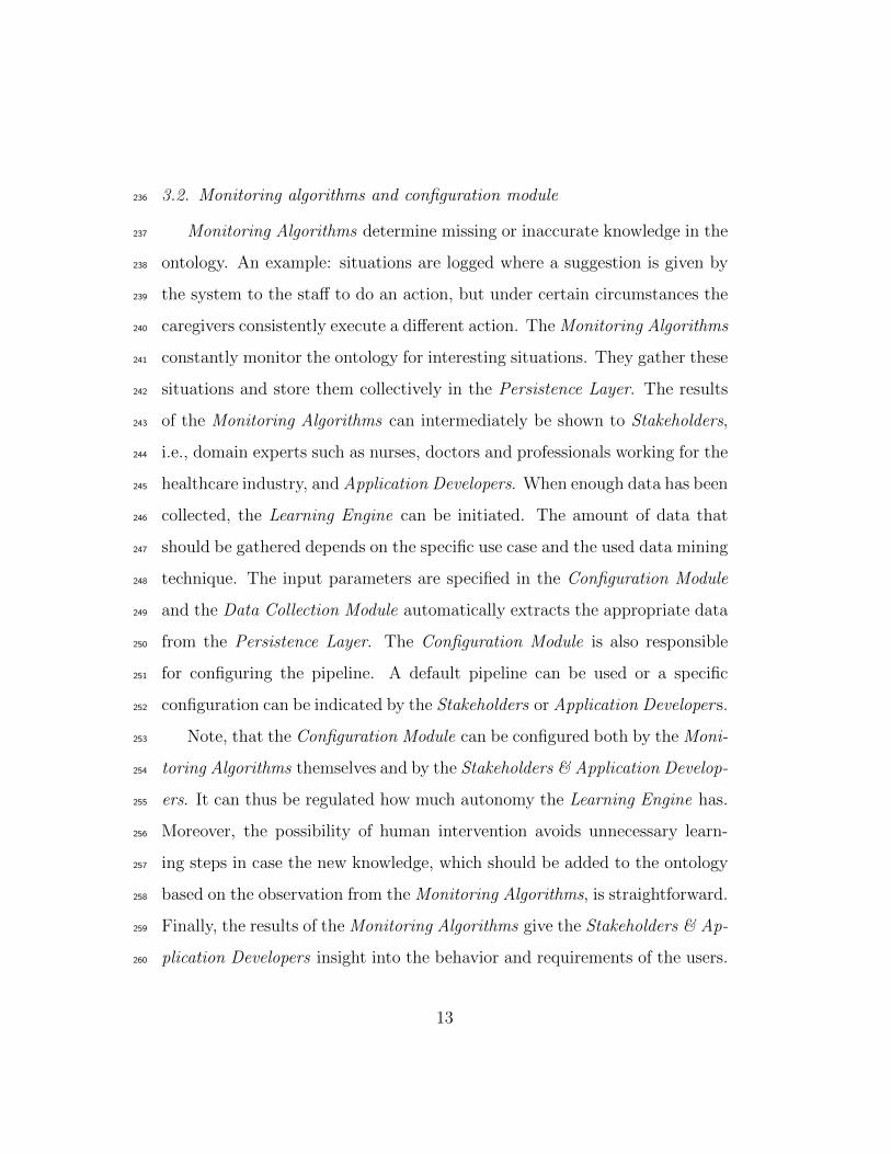
3.2. Monitoring algorithms and configuration module236
Monitoring Algorithms determine missing or inaccurate knowledge in the237
ontology. An example: situations are logged where a suggestion is given by238
the system to the staff to do an action, but under certain circumstances the239
caregivers consistently execute a different action. The Monitoring Algorithms240
constantly monitor the ontology for interesting situations. They gather these241
situations and store them collectively in the Persistence Layer. The results242
of the Monitoring Algorithms can intermediately be shown to Stakeholders,243
i.e., domain experts such as nurses, doctors and professionals working for the244
healthcare industry, and Application Developers. When enough data has been245
collected, the Learning Engine can be initiated. The amount of data that246
should be gathered depends on the specific use case and the used data mining247
technique. The input parameters are specified in the Configuration Module248
and the Data Collection Module automatically extracts the appropriate data249
from the Persistence Layer. The Configuration Module is also responsible250
for configuring the pipeline. A default pipeline can be used or a specific251
configuration can be indicated by the Stakeholders or Application Developers.252
Note, that the Configuration Module can be configured both by the Moni-253
toring Algorithms themselves and by the Stakeholders & Application Develop-254
ers. It can thus be regulated how much autonomy the Learning Engine has.255
Moreover, the possibility of human intervention avoids unnecessary learn-256
ing steps in case the new knowledge, which should be added to the ontology257
based on the observation from the Monitoring Algorithms, is straightforward.258
Finally, the results of the Monitoring Algorithms give the Stakeholders & Ap-259
plication Developers insight into the behavior and requirements of the users.260
13
3.3. Learning engine261
The Pipes-and-Filters architectural design pattern (Bass et al., 2003) was262
used to design the Learning Engine. This data-driven pattern divides a263
larger processing task into a sequence of smaller, independent processing264
steps, called filters, that are connected by channels, called pipes. Each filter265
provides a simple interface, namely it receives messages on the incoming pipe,266
processes them and provides the results to the outgoing pipe. A filter is thus267
unaware of its position in the pipeline and which filter precedes and follows268
it. Because all the filters use similar interfaces they can be combined into269
different pipelines. Filters can thus easily be added, omitted or rearranged.270
As a result, the architecture becomes very modular, extensible, re-usable and271
flexible.272
3.3.1. Data collection & input conversion273
To be able to use a flexible Pipes-and-Filters architecture, the data ex-274
changed between the filters needs to be expressed in the same format. A275
format was developed, which allows expressing both the information which276
is used as input and the knowledge that is obtained as output, e.g., rules.277
The format is largely based on the Attribute-Relation File Format (ARFF),278
which is the text file format used by WEKA (Witten et al., 2011).279
The Data Collection Module is responsible for gathering the necessary280
input information for the Learning Engine from the Persistence Layer. The281
Input Convertor converts this data to the data format used by the Learning282
Pipeline. The Data Collection Module and Input Convertor cannot be con-283
sidered as actual filters for two reasons. First, for any use case scenario they284
will always appear as the first two steps of the pipeline. Second, the input285
14
and output format of these modules is dependent on the source from which286
the information is collected, e.g., a triple store.287
3.3.2. Learning pipeline288
The Pre-Processor contains several modules to clean up the data. For289
example, the Remove Outliers component removes unrealistic entries from290
the input data, e.g., impossible sensor values. The Scale component centers291
the input values at zero. This is often beneficial for the learning algorithms292
of various machine learning techniques. Feature Selection can be used to293
reduce the size of the input data set and thus speed up the data mining.294
Other examples of pre-processing techniques can easily be integrated into295
the pipeline as new Filters.296
The cleaned data is then passed to the Data Mining component that pro-297
vides several techniques to discover trends, e.g., classification rules, decision298
trees, Bayesian networks or clustering. The results of the Data Mining are299
then processed by the Post-Processor to derive the actual information which300
can be added to the ontology, e.g., rules or thresholds can be derived from a301
decision tree by the Rule or Threshold Extractor.302
The conclusions of the Post-Processor are studied further by the Decision303
Module. To ensure that the Knowledge Base does not become inconsistent304
when the new knowledge is added, i.e., because it contradicts with already305
defined knowledge, probabilistic relations are defined between the new and306
existing knowledge. Moreover, this probability also makes clear to the Stake-307
holders that the new knowledge has not been confirmed by rigorous evalua-308
tion yet. The Probabilistic Relevance Algorithms are used to determine the309
initial probability that should be associated with this new knowledge. For310
15
hasConfiguration
ThingaddedBy
addedBy
Person
Learning
Engine
Pipeline
hasPipeline
Filter
composedOf
Pre
Processor
DataMining
Technique
Post
Processor
Decision
Module
hasNextFilter
Configuration
hasDataSetURL
addedAtTp
temp:ValidInstant
probabilityChangedBy
probabilityChangedBy
double
associated
Probability
hasInputConvertor
hasDataCollectionModule
hasIntegrationModule
DataCollectionModule
InputConvertor
IntegrationModule
FileDataCollector
ARFFInputConvertor
ContextCall
IntegrationModule
TreeMiner BooleanRule
Extractor
CounterRelevance
Algorithm
ThresholdFilter
Algorithm
ARFFDecision
TreeEngine
85
Legend
Ontology Concept
Object Property/Relation
Datatype Property
Inheritance
Instantiation
Concept
relation
property data
type
Individual
Figure 2: The Learning Ontology
example, it can be calculated how many times a derived rule occured in the311
data set on which the data mining technique was trained. However, wrong312
trends can easily be detected because of skewed or too small data sets. It313
is also important to only include trends that reflect good and general work314
practices. Wrong information could clutter the Knowledge Base and make315
the context-aware platform less useable. The Filter Algorithms are responsi-316
ble for detecting and removing these anomolies, e.g., by removing knowledge317
that received a too low probability by the Probabilistic Relevance Algorithms.318
The Learning Pipeline cannot only be used to learn new information, but319
also to reassess knowledge that has been previously added to the Knowledge320
Base. In this case, the Probabilistic Relevance Algorithms are responsible321
for in- or decreasing the probability depending on the new information that322
becomes available about the usage of this knowledge.323
16

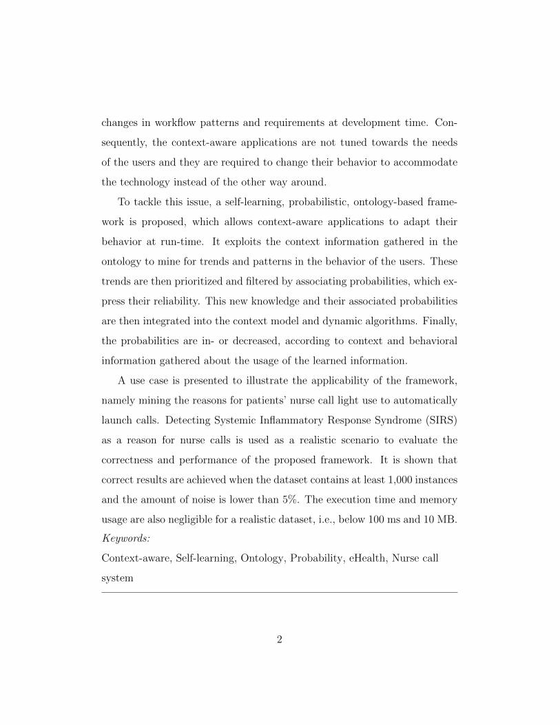
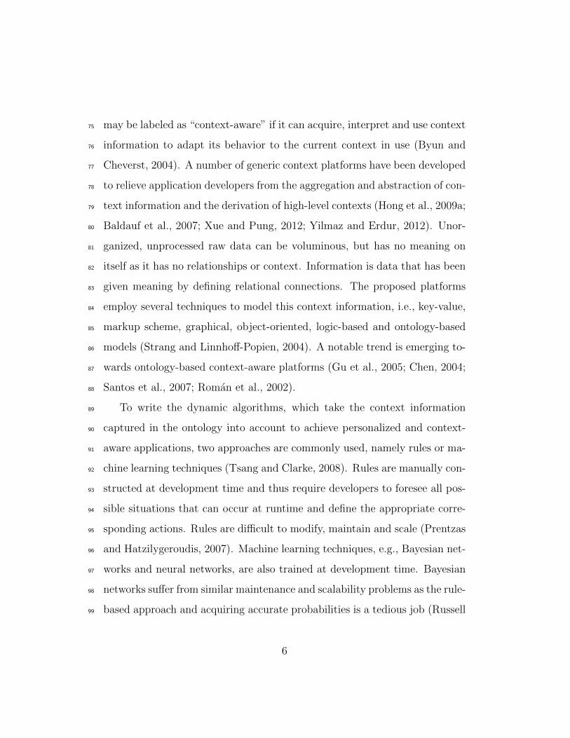
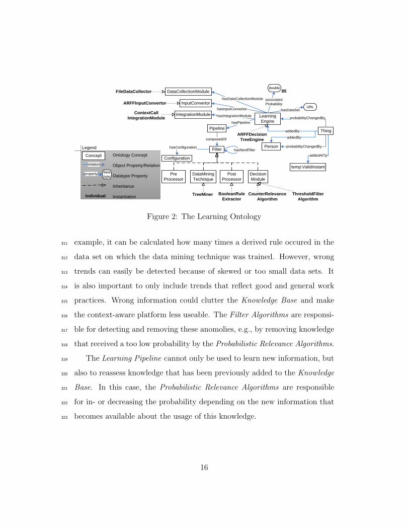
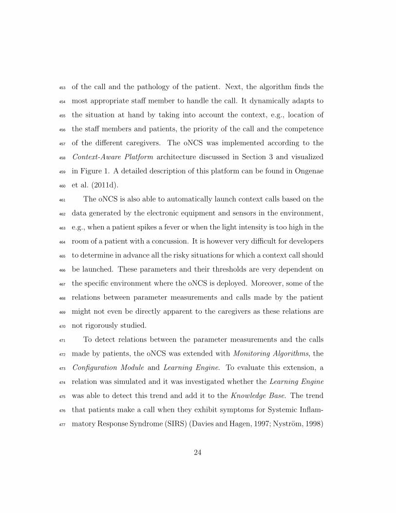
3.3.3. Integration module & adapting the probabilities324
Finally, the Integration Module is responsible for defining the probabilis-325
tic relations that connect the new knowledge to the existing knowledge in326
the Knowledge Base. For the same reasons as were already explained in Sec-327
tion 3.3.1 for the Data Integration and Input Convertor Modules, this module328
cannot really be considered a filter.329
For new knowledge, the probability calculated by the Probabilistic Rel-330
evance Algorithms is used. When the Stakeholders are confronted with a331
probabilistic decision in their daily work practices, they might be interested332
in the origin of the information, i.e., how the information was learned, be-333
fore deciding to follow the recommendation of the context-aware platform or334
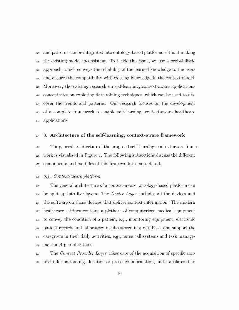
not. Therefore, the Learning Ontology was created, which allows associat-335
ing the learned knowledge with its origin. The most important concepts of336
this ontology are visualized in Figure 2. This ontology also allows Applica-337
tion Developers to easily identify learned knowledge. This enables them to338
treat this knowledge differently if needed, e.g., ignore it in reliability critical339
applications or highlight it for the users.340
For reassessed knowledge, two thresholds are checked. If the probability341
calculated by the Probabilistic Relevance Algorithms falls below the lowest342
threshold, the knowledge is removed from the Knowledge Base as it is clearly343
not being used or confirmed by the stakeholders. If the probability exceeds344
the highest threshold, the knowledge is added to the ontology as generally345
accepted knowledge, i.e., without an associated probability. Finally, if the346
probability lies between the two thresholds, the probabilitiy of the reassessed347
knowledge is updated to this probability to reflect its changed reliability. As348
17
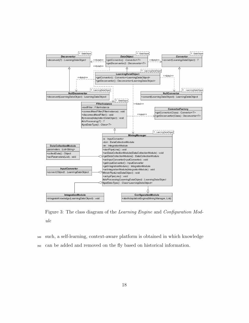
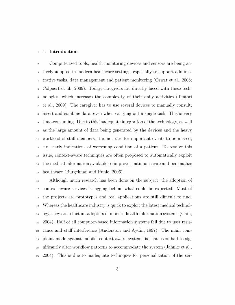
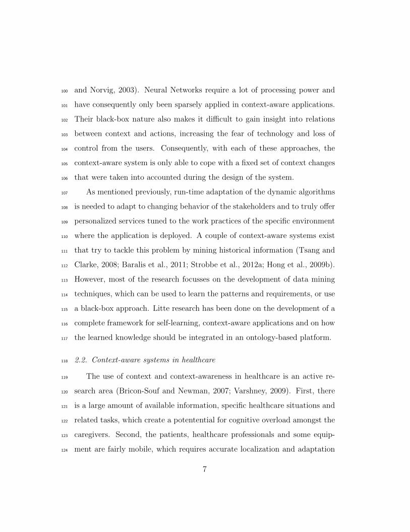
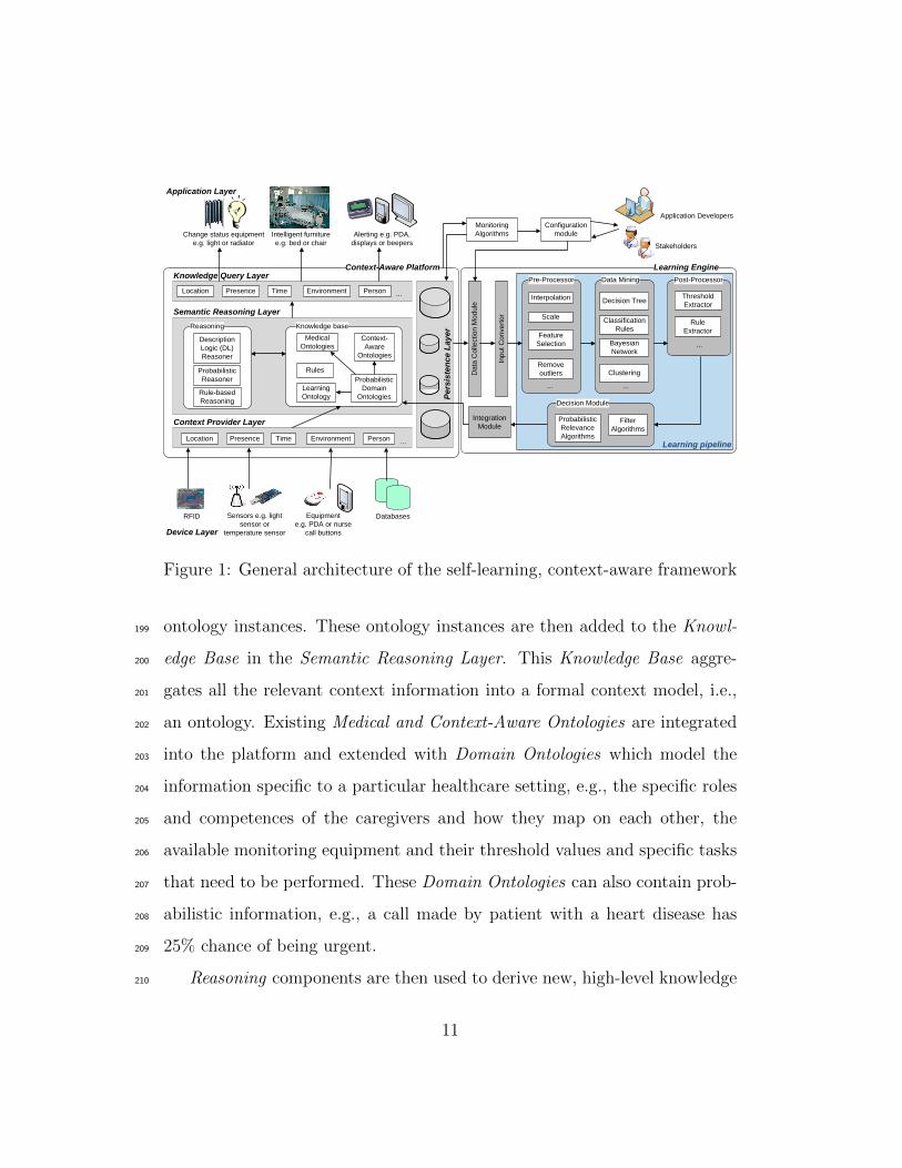
Figure 3: The class diagram of the Learning Engine and Configuration Mod-
ule
such, a self-learning, context-aware platform is obtained in which knowledge349
can be added and removed on the fly based on historical information.350
18
4. Implementation details351
The implementation details of the Context-Aware Platform are described352
in Strobbe et al. (2007, 2012b). The platform uses OWL (McGuinness and353
Harmelen, 2004) as ontology language, Pellet (Sirin et al., 2007) as DL Rea-354
soner, Jena Rules (Carroll et al., 2004) and SWRL (Horrocks et al., 2004)355
to express the Rules and SPARQL (Prud’hommeaux and Seaborne, 2008) to356
query the context information. The platform was extended with the Proba-357
bilistic Reasoner Pronto (Klinov, 2008) to enable probabilistic reasoning on358
the ontologies. Jena is used to manage and persist the ontologies.359
The Learning Engine, Monitoring Algorithms and Configuration Module360
were implemented in Java. The class diagram of the Learning Engine is361
visualized in Figure 3. These are the (abstract) classes, which can be used for362
any scenario. To implement a specific use case, subclasses can be created that363
implement the specific requirements of the scenario, e.g., a specific pipeline364
configuration or a specific input convertor. An example of how a specific use365
case can be implemented is thoroughly explained in Section 5. How these366
classes can be used to construct and use a specific Learning Pipeline with367
associated Data Collection Module, Input Convertor and Integration Module368
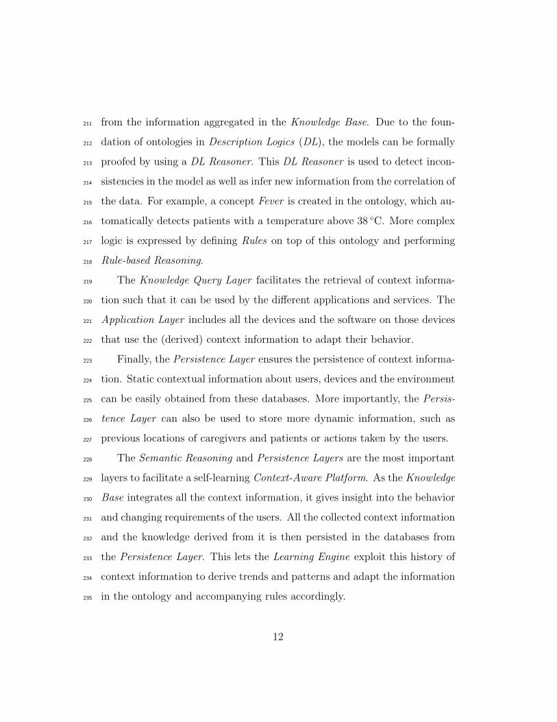
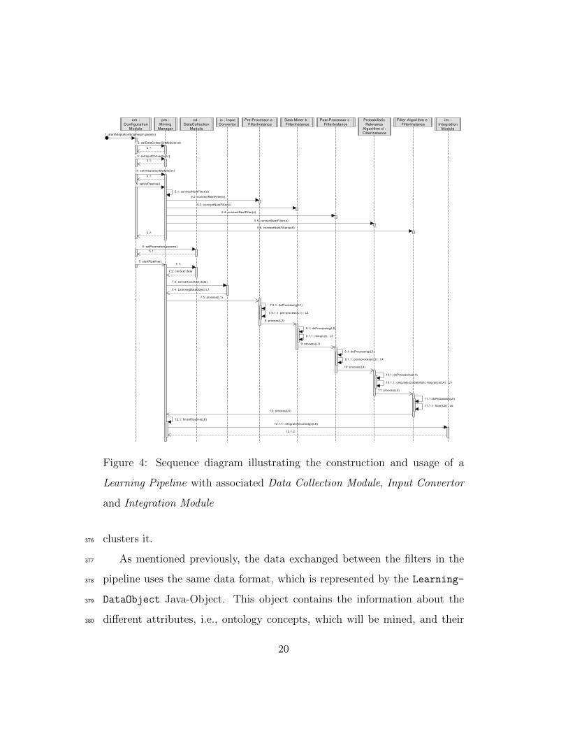
is visualized with a sequence diagram in Figure 4.369
As can be seen, the different filters in the Learning Pipeline are resp-370
resented by FilterInstance objects. Specific filters, e.g., pre- and post-371
processors, filter algorithms and data mining techniques, are created as sub-372
classes of this FilterInstance class by implementing the doProcessing373
method. This method specifies how the data is processed by the specific374
filter, e.g., a ScalingFilter that scales the data or a ClusterFilter that375
19
cm :Configuration
Module
im :Integration
Module
Filter Algorithm e :FilterInstance
ProbabilisticRelevance
Algorithm d :FilterInstance
Post-Processor c :FilterInstance
Data Miner b :FilterInstance
Pre-Processor a :FilterInstance
ic : InputConvertor
cd :DataCollection
Module
pm :Mining
Manager
1: startAdaptationEngine(pm,params)
7: startPipeline()
6: setParameters(params)
5: setUpPipeline()
4: setIntegrationModule(im)
3: setInputConvertor(ic)
2: setDataCollectionModule(cd)
6.1:
5.7:
4.1:
3.1:
2.1:
12.1.2:
12.1.1: integrateKnowledge(L6)
12: process(L6)
11.1.1: filter(L5) : L6
11.1: doProcessing(L5)
11: process(L5)
5.6: connectNextFilter(self)
10.1.1: calculate probabilistic relevance(L4) : L5
10.1: doProcessing(L4)
10: process(L4)
5.5: connectNextFilter(e)
9.1.1: post-process(L3) : L4
9.1: doProcessing(L3)
9: process(L3)
5.4: connectNextFilter(d)
8.1.1: mine(L2) : L3
8.1: doProcessing(L2)
8: process(L2)
5.3: connectNextFilter(c)
7.5.1.1: pre-process(L1) : L2
7.5.1: doProcessing(L1)
7.5: process(L1)
5.2: connectNextFilter(b)
7.4: LearningDataObject L1
7.3: convert(context data)
7.2: context data
7.1:
12.1: finishPipeline(L6)
5.1: connectNextFilter(a)
Figure 4: Sequence diagram illustrating the construction and usage of a
Learning Pipeline with associated Data Collection Module, Input Convertor
and Integration Module
clusters it.376
As mentioned previously, the data exchanged between the filters in the377
pipeline uses the same data format, which is represented by the Learning-378
DataObject Java-Object. This object contains the information about the379
different attributes, i.e., ontology concepts, which will be mined, and their380
20
data instances. However, to enable logging of the data at any point during381
the pipeline, this object can easily be serialized to XML.382
As can be seen, (de)convertors can be used to translate the specific data383
format to other formats. This is not only necessary to convert the context384
data gathered by the Context-Aware Platform to the data format used by385
the pipeline, but also to allow the usage of external libraries, e.g., WEKA for386
data mining. The (de)convertors allow to transform the LearningDataOb-387
ject to the format used by the external libraries, e.g., the ARFF format388
used by WEKA. Each FilterInstance indicates which datatype it employs389
to process the data by using ‘generic types ’. Based on the indicated type,390
the framework is able to automatically find the appropriate Convertor and391
Deconvertor. This eases the development of specific use cases and the usage392
of external libraries. The Application Developers only have to develop Con-393
vertor and Deconvertor subclasses that implement the conversion to the394
specific file format used by the FilterInstance.395
To manage the complete pipeline, a special type of FilterInstance was396
created, namely the MiningManager. This class is responsible for construct-397
ing the Learning Pipeline out of the separate filters, starting it and processing398
the results. To implement a specific Learning Pipeline, a subclass of the Mi-399
ningManager needs to be constructed that implements the setupPipeline400
method. This method initializes the different filters of the pipeline and con-401
nects them to each other. Each FilterInstance is connected to the next402
FilterInstance in the pipeline by using the connectNextFilter method.403
The first FilterInstance is connected to the MiningManager, while the last404
FilterInstance indicates the MiningManager as next filter to ensure proper405
21

processing of the result of the Learning Pipeline.406
The ConfigurationModule is notified of which data should be collected407
for the mining process, either by the Stakeholders and Application Develop-408
ers or by the Monitoring Algorithms. It configures the MiningManager to409
use the appropriate DataCollectionModule, InputConvertor and Integra-410
tionModule that suits this type of data. It also passes the correct parameters411
to the DataCollectionModule, which are needed to retrieve the data from412
the Persistency Layer. Next, the ConfigurationModule calls the setup-413
Pipeline and startPipeline methods of the MiningManager to create the414
pipeline and start the learning process. The latter method first collects the415
necessary data by using the associated DataCollectionModule and converts416
it to the LearningDataObject format with the InputConvertor. Next, the417
MiningManager calls the process method of the first FilterInstance in the418
pipeline. This FilterInstance processes the data with its doProcessing419
method and then calls the process method of the next FilterInstance in420
the pipeline. This continues until the last FilterInstance calls the process421
method of the MiningManager. The MiningManger then finishes the learning422
process by calling the IntegrationModule to integrate the knowledge in the423
Knowledge Base.424
It can be noted that the implemented framework is very extensible, mod-425
ular and flexible, which allows easy adoption for any use case, as illustrated426
in the following section.427
22
5. Use case: Mining the reasons for patients’ call light use to au-428
tomatically launch calls429
5.1. Scenario description430
Nurse call systems are a fundamental technology in continuous care as431
they are used by caregivers to coordinate work, be alerted of patients’ needs,432
communicate with them through intercoms and request help from other staff433
members. When patients feel unwell they push a button. The nurses then434
receive a message with the room number on a beeper. This brings up the435
question: which nurse goes to the room? The closest one? the one on call,436
etc.? Current systems often have a very static nature as call buttons have437
fixed locations, e.g., on the wall next to the bed. There is an increased438
risk when patients become unwell inside a hallway, staircase or outside as439
they cannot use the nurse call system. Additionally, the current nurse call440
algorithms consist of predefined links between beeper numbers and rooms.441
Consequently, the system presently does not take into account the various442
factors specific to a given situation, such as the pathology of a patient, e.g.,443
heart patient or confused, nor the competences of the staff, e.g., nurse or444
caregiver.445
The increased introduction of electronic devices in continuous care set-446
tings facilitated the development of the ontology-based Nurse Call System447
(oNCS), which allows patients to walk around freely and use wireless nurse448
call buttons. Additionally, this platform manages the profiles of staff mem-449
bers and patients in an ontology. A sophisticated nurse call algorithm was450
developed by the authors. It first determines the priority of the call us-451
ing probabilistic reasoning algorithms, which take into account the origin452
23
of the call and the pathology of the patient. Next, the algorithm finds the453
most appropriate staff member to handle the call. It dynamically adapts to454
the situation at hand by taking into account the context, e.g., location of455
the staff members and patients, the priority of the call and the competence456
of the different caregivers. The oNCS was implemented according to the457
Context-Aware Platform architecture discussed in Section 3 and visualized458
in Figure 1. A detailed description of this platform can be found in Ongenae459
et al. (2011d).460
The oNCS is also able to automatically launch context calls based on the461
data generated by the electronic equipment and sensors in the environment,462
e.g., when a patient spikes a fever or when the light intensity is too high in the463
room of a patient with a concussion. It is however very difficult for developers464
to determine in advance all the risky situations for which a context call should465
be launched. These parameters and their thresholds are very dependent on466
the specific environment where the oNCS is deployed. Moreover, some of the467
relations between parameter measurements and calls made by the patient468
might not even be directly apparent to the caregivers as these relations are469
not rigorously studied.470
To detect relations between the parameter measurements and the calls471
made by patients, the oNCS was extended with Monitoring Algorithms, the472
Configuration Module and Learning Engine. To evaluate this extension, a473
relation was simulated and it was investigated whether the Learning Engine474
was able to detect this trend and add it to the Knowledge Base. The trend475
that patients make a call when they exhibit symptoms for Systemic Inflam-476
matory Response Syndrome (SIRS) (Davies and Hagen, 1997; Nystrom, 1998)477
24

was chosen as simulated relation. This medically relevant use case could be478
easily generated, but is challenging for the Learning Engine to detect. SIRS479
is a generalized inflammatory reaction of the organism to a severe medical480
condition such as acute pancreatitis, severe burn injury, trauma, surgical481
procedure or infection. If SIRS is the response to an infection, the patient482
is diagnosed with sepsis. Sepsis has a high mortality rate (30%-40%). The483
criteria for diagnosing a patient with SIRS are:484
• Tachycardia: heart rate > 90 beats per minute (bpm)485
• Fever or hypothermia: body temperature > 38 ◦C or < 36 ◦C486
• Tachypnea: arterial partial pressure of carbon dioxide (PaCO2) < 32487
mmHg488
• White Blood Cell (WBC) count < 4,000 cells/mm3 or > 12,000 cells/mm3489
For the diagnosis of SIRS, two or more of these criteria must be fulfilled. This490
is a challenging scenario for the Learning Engine as it involves both param-491
eters measured at regular intervals by sensors, i.e., the heart rate and body492
temperature, as well as parameters obtained through the analysis of a blood493
sample by the laboratory, i.e., WBC and PaCO2. Moreover, a combination494
of conditions needs to be fulfiled before the call should be launched.495
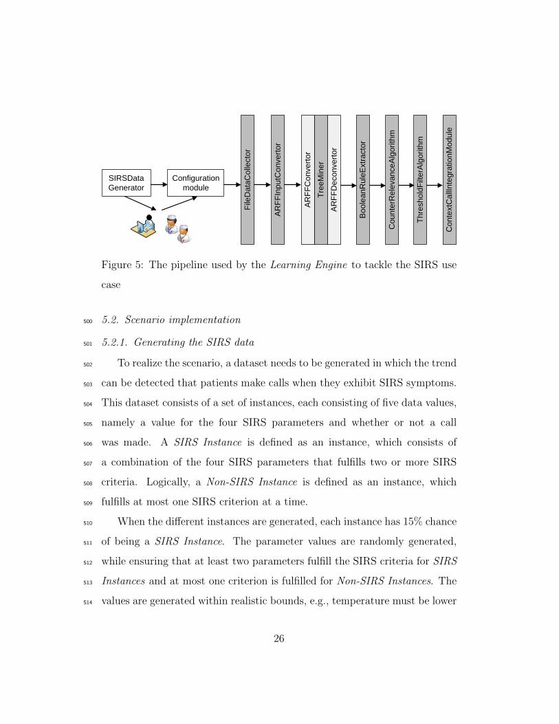
The following sections illustrate how the Learning Engine was imple-496
mented and the Learning Pipeline was constructed, using the (abstract)497
classes discussed in Section 4, to detect this relation and add it to the Knowl-498
edge Base. The resulting pipeline is visualized in Figure 5.499
25
Configuration
module
SIRSData
Generator
File
Da
taC
olle
cto
r
AR
FF
Inp
utC
on
ve
rto
r
Tre
eM
ine
r
AR
FF
Co
nve
rto
r
AR
FF
De
co
nve
rto
r
Th
resh
old
Filt
erA
lgo
rith
m
Co
nte
xtC
allI
nte
gra
tio
nM
od
ule
Co
un
terR
ele
va
nce
Alg
orith
m
Bo
ole
an
Ru
leE
xtr
acto
r
Figure 5: The pipeline used by the Learning Engine to tackle the SIRS use
case
5.2. Scenario implementation500
5.2.1. Generating the SIRS data501
To realize the scenario, a dataset needs to be generated in which the trend502
can be detected that patients make calls when they exhibit SIRS symptoms.503
This dataset consists of a set of instances, each consisting of five data values,504
namely a value for the four SIRS parameters and whether or not a call505
was made. A SIRS Instance is defined as an instance, which consists of506
a combination of the four SIRS parameters that fulfills two or more SIRS507
criteria. Logically, a Non-SIRS Instance is defined as an instance, which508
fulfills at most one SIRS criterion at a time.509
When the different instances are generated, each instance has 15% chance510
of being a SIRS Instance. The parameter values are randomly generated,511
while ensuring that at least two parameters fulfill the SIRS criteria for SIRS512
Instances and at most one criterion is fulfilled for Non-SIRS Instances. The513
values are generated within realistic bounds, e.g., temperature must be lower514
26
than 43 ◦C. Whether the SIRS Instance fulfills two, three or four criteria515
and whether the Non-SIRS Instance fulfills one criterion or none, is also516
randomly chosen.517
Finally, each instance needs to be associated with a context call or not.518
To achieve a realistic dataset, noise is introduced by wrongly classifying the519
instances, i.e., associating Non-SIRS Instances with a call and vice versa. A520
noise percentage of x means that each Non-SIRS Instance has x% chance of521
being associated with a call and vice versa.522
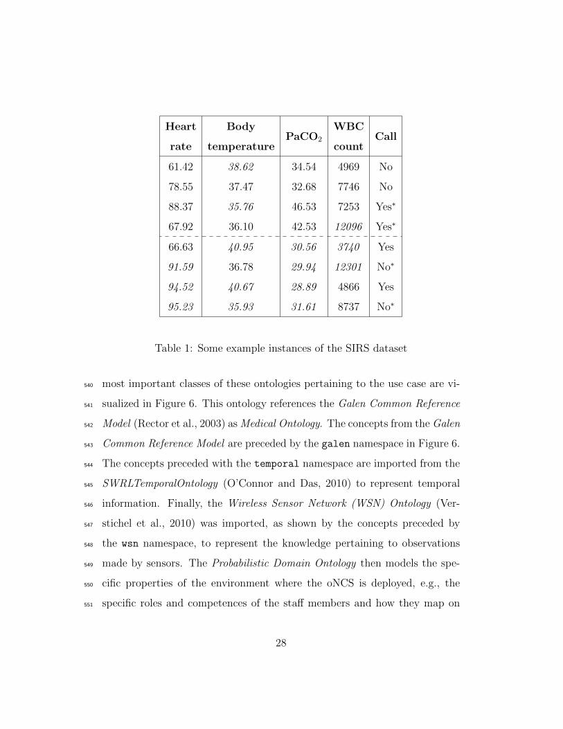
Some example instances are illustrated in Table 1. The first four instances523
are Non-SIRS Instances, while the latter four are SIRS Instances. The pa-524
rameter values that fulfill SIRS criteria are indicated in italic. The calls525
marked with a ∗-symbol represent noise. A Data Generator was written to526
create the needed instances and provide them in the ARFF format, i.e., the527
data format used by WEKA. The resulting file is stored in the Persistence528
Layer.529
5.2.2. The oNCS and continuous care ontologies530
As mentioned in Section 2, little work has been done on the development531
of high-level ontologies, which can be used to model context information and532
knowledge utilized across the various continuous care settings, e.g., hospitals,533
homecare and residential care settings. Therefore we developed the Continu-534
ous Care Ontology, which models the generic context information gathered by535
the various sensors and devices, the different devices, the various staff mem-536
bers and patients and their profile information, medical conditions, roles and537
competences and the variety of tasks that need to be performed. A detailed538
description of this ontology can be found in Ongenae et al. (2011a). The539
27
Heart BodyPaCO2
WBCCall
rate temperature count
61.42 38.62 34.54 4969 No
78.55 37.47 32.68 7746 No
88.37 35.76 46.53 7253 Yes∗
67.92 36.10 42.53 12096 Yes∗
66.63 40.95 30.56 3740 Yes
91.59 36.78 29.94 12301 No∗
94.52 40.67 28.89 4866 Yes
95.23 35.93 31.61 8737 No∗
Table 1: Some example instances of the SIRS dataset
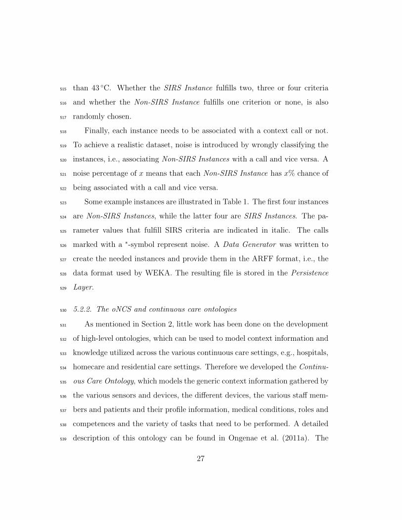
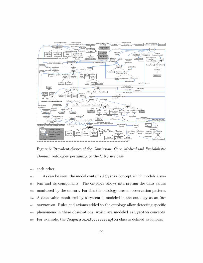
most important classes of these ontologies pertaining to the use case are vi-540
sualized in Figure 6. This ontology references the Galen Common Reference541
Model (Rector et al., 2003) as Medical Ontology. The concepts from the Galen542
Common Reference Model are preceded by the galen namespace in Figure 6.543
The concepts preceded with the temporal namespace are imported from the544
SWRLTemporalOntology (O’Connor and Das, 2010) to represent temporal545
information. Finally, the Wireless Sensor Network (WSN) Ontology (Ver-546
stichel et al., 2010) was imported, as shown by the concepts preceded by547
the wsn namespace, to represent the knowledge pertaining to observations548
made by sensors. The Probabilistic Domain Ontology then models the spe-549
cific properties of the environment where the oNCS is deployed, e.g., the550
specific roles and competences of the staff members and how they map on551
28
wsn:hasobservation
(inverse: isObservationOf)
wsn:Actionwsn:Fault
wsn:Observation
wsn:Solutionwsn:Symptom
wsn:Threshold
Symptom
Temperature
Above38Symptom
wsn:hasFault (inverse:
isFaultOf)
wsn:hasSymptom
(inverse: isSymptomOf)wsn:requiresAction
(inverse: isActionOf)
wsn:hasSolution
(inverse:
isSolutionForFault)
temporal:
ValidInstant
wsn:observed
AtTimepoint
xsd:floatwsn:hasValue
wsn:System
wsn:
Sensor
Body:
Temperature
Sensor
Heart
Rate
Sensor
wsn:hasSensorPart
(inverse: isSensor
PartOf)
Body
Temperature
Observation
Actuator
Light
xsd:string
Magnetic
Lock
xsd:floathasValue
hasUnit
xsd:string
hasUnit
Nurse
CallButton
Pressed
NurseCall
Button
Normal
CallButton
Urgency
CallButton
Device
Portable
Electronic
Device
CellPhone
TV
hasStatus
Smart
PhonePDA
Device
Status
on off
Status
Location
ZoneCoordinate
DepartmentRoom
containsRoom
hasCentre
Coordinate
isOnDepartment
xsd:double
radius
hasLocation
(inverse:
isLocationOf)constainsSystem
Heart
Rate
Observation
xsd:dateTime
temporal:
hasTime
Person
Competence RolehasCompetence
(inverse:
belongsToRole)
Staff
MedicalRole
CareRole
Patient
hasExperience
CompetencehasDiploma
Competence
hasRole
(inverse: isRoleOf)
hasLocation
(inverse:
isLocationOf)
loggedInto
Device
owns
Device
associatedWith
family:Family
galen:Named
Disorder
MeasureType
DerivedLaboratoryObserved MonitoredMedical
Parameter
PaCO2WBC galen:Body
Temperature
Armpit
Temperature
Blood
Temperature
Rectal
Temperature
Diagnosis
Medical
Diagnosis
Sample
galen:Urine
Sample
galen:Blood
Sample
galen:has_diagnosis
(inverse: diagnosisOf)hasMedicalParamEter
(inverse: isMedicalParameterOf)
diagnosedBy
Fever Diabetes
hasAssociated
Pathology
hasSample
(inverse: isSampleOf)
hasAssociated
SamplehasMeasurement
Type
Derived
Medical
Parameter
Labo
Medical
Parameter
Observed
Medical
Parameter
Monitored
Medical
Parameter
analyzedByLabo
AtTimepoint
MonitoredAt
Timepoint xsd:float
xsd:string
hasUnit
PlannedTaskUnPlannedTask
Call
AssistanceCallNormalCall
Task
Priority hasPriority
Normal
Priority
Urgent
Priority
VeryUrgent
Priority
Task
Status
AssignedFinished Active
Reason
Medical
Reason
Care
Reason
HotelFunction
Reason
hasReason
UrgencyCall ContextCall
Medical
Context
Call
Care
Context
Call
HotelFunction
ContextCall
Accepted
isAssignedTo
(inverse: assignedTo)
makesCall
(inverse:
callMadeBy)
requiresCompetence
hasSequenceNumber
executedByexecutedOn
hasTODOTaskshasCurrentTask
acceptedBy
makesCall
(inverse: callMadeBy)
Fever
ContextCallhasReason
hasReason
hasReasonhasReason
hasStatus
ID
xsd:string
hasIDType hasID
xsd:string
hasValue
Heart
Rate
xsd:boolean
hasAssociatedCall
HeartRateAbove
90Symptom
PaCO2Below
32Symptom
WBCBelow
4000Symptom
hasNextObservation
hasNextValue
SIRS
ContextCall
SIRS
Reason
85%
Legend
Ontology Concept
Object Property/Relation
Datatype Property
Inheritance
Instantiation
Concept
relation
property data
type
Individual
Figure 6: Prevalent classes of the Continuous Care, Medical and Probabilistic
Domain ontologies pertaining to the SIRS use case
each other.552
As can be seen, the model contains a System concept which models a sys-553
tem and its components. The ontology allows interpreting the data values554
monitored by the sensors. For this the ontology uses an observation pattern.555
A data value monitored by a system is modeled in the ontology as an Ob-556
servation. Rules and axioms added to the ontology allow detecting specific557
phenomena in these observations, which are modeled as Symptom concepts.558
For example, the TemperatureAbove38Symptom class is defined as follows:559
29
BodyTemperatureObservation AND ∃hasValue “ > 38”
This axiom ensures that a BodyTemperatureObservation of more than560
38 ◦C is reclassified as a TemperatureAbove38Symptom. Similarly, symptoms561
can also be reclassified as faults and even as solutions and actions that should562
be taken.563
People are modelled through the Person concept and their roles and564
competences can be indicated. It can also be indicated with which person565
the sensors are associated through the associatedWith relationship. The566
medical parameters collected about a patient, either by sensors, the obser-567
vations of staff members or the analysis of blood samples, are modelled as568
MedicalParameters. Similar to observations, these parameters can also be569
reclassified as symptoms. The medical condition of a person can also be570
modeled, e.g., Fever.571
To model the daily activities of the caregivers and patients, the Task572
concept is used, which is further divided into planned and unplanned tasks.573
Each task can be assigned a Status, e.g., Active or Finished, a Priority574
and the competences which are needed to execute the task. People can be575
connected to the tasks through various relationships, e.g., hasCurrentTask,576
isAssignedTo or executedBy. A Call is modelled as an unPlannedTask. A577
call can be associated with a Reason, e.g., Fever. Four types of calls can be578
discerned. A NormalCall is a call made by a patient, while an Assistance-579
Call is launched by a caregiver to request help from another staff member.580
An UrgencyCall is only used for emergency situations, e.g., when a patient581
needs to be reanimated. Finally, a ContextCall is call that is automatically582
30
generated by the oNCS as a consequence of certain conditions being fulfilled.583
Consider for example the following Jena rule:584
[FeverContextCall:
(?symp rdf:type oncs:TemperatureAbove38Symptom)
noValue(?symp task:hasAssociatedCall)
(?symp wsn:isObservationOf ?system)
(?kind rdf:type oncs:FeverContextCall)
→
createContextCall(?system, ?kind)
(?symp task:hasAssociatedCall ‘true’ xsd:boolean)]
The first line represents the name of the rule. First, it is sought if a585
body temperature of more than 38 ◦C was observed for which a call has not586
been launched yet. Next, the system that made the observation is retrieved.587
Finally, the type of call that should be created is specified. As a result, the588
functor createContextCall is called, which creates a ContextCall of type589
FeverContextCall and associates the system that made the observation with590
this call. The functor also assigns the status Active to the call. Moreover,591
the hasAssociatedCall relationship is set to true to make sure that the592
rule does not fire again.593
The oNCS contains rules that fire when active calls are added to the594
ontology. Based on the context information, these rules assign the most ap-595
propriate staff member to the call. More information about these assignment596
31
rules can be found in Ongenae et al. (2011d).597
Similar to how the fever example was modeled, the SIRS use case can598
be easily represented using these classes. Individuals of type BodyTempera-599
tureSensor and HeartRateSensor are created to represent the sensors that600
measure the medical parameters of the patients. These sensors make obser-601
vations of type BodyTemperatureObservation and HeartRateObservation602
respectively, which are associated with their sensors through the hasObser-603
vation relation. The measured value is indicated with the hasValue relation.604
Individuals of type BloodSample are created, that represent the blood sam-605
ples analyzed by the laboratory to determine the WBC count and PaCO2 of606
the patient. These results are captured in the ontology as medical parameters607
of type WBC and PaCO2. They are associated with their blood sample through608
the hasAssociatedSample relationship. Finally, when a patient makes a call609
by pressing a button, an individual of type Call is created in the ontology,610
which is connected through the callMadeBy relationship with the patient.611
Through reasoning, this call is reclassified as a NormalCall as it is made by612
a person with as role Patient.613
A mobile nurse call application was also developed, which is used by the614
caregivers to receive, assess and accept, i.e., indicate that they are going to615
handle, calls. A nurse can also use the application to contact other staff616
members or the patient, e.g., to request the reason for the call or to give617
feedback. Before a nurse is able to indicate a call as finished, the reason for618
the call must be indicated either on the mobile application or the terminal619
next to the bed of the patient. This reason is also entered in the ontology.620
The mobile application is further explained in Ongenae et al. (2011c).621
32
5.2.3. Collecting the data & input conversion622
As the data is generated, no Monitoring Algorithms are needed. However,623
a Monitoring Algorithm could easily be written as follows. Relationships624
need to be found between medical parameters of patients and the calls that625
they make. The Context Call Monitoring Algorithm, monitors the ontology626
for calls of type NormalCall. When such a call is added to the ontology,627
the algorithm collects the most recent value for each medical parameter that628
is measured about the patient who made the call. This information can629
easily be retrieved using SPARQL queries. As not every medical parameter630
is measured for every patient, the dataset possibly contains missing values.631
When the call has been completely handled by the caregiver, the algorithm632
also retrieves the reason, which was attached to the call. As such, different633
data sets can be created, grouping calls together which have similar reasons.634
These datasets can differ in granularity of the reason. For example, a dataset635
could be created for all the calls with a MedicalReason or for all the calls636
with the more specific reason Fever. All calls of the second dataset would637
also be part of the first dataset, as Fever is a subclass of MedicalReason.638
Each of these datasets could be used as input for the Learning Engine. Other639
ways of grouping the data instances can also be employed, e.g., grouped per640
patient or grouping the instances of patients that have a similar pathology.641
The Context Call Monitoring Algorithm keeps track of how many instances642
have been collected for each dataset. When a representative amount has been643
gathered, the dataset is expanded with negative examples. For example, the644
medical parameters of the patients already present in the dataset can be645
collected at a timepoint when they have not seen a caregiver or made a call646
33
for a while or at a timepoint they made a call for a different reason. Finally,647
the Monitoring Algorithms invoke the Configuration Module to initiate the648
Learning Engine. The datasets can also be intermediately shown to the649
Stakeholders and Application Developers for inspection. In this use case, the650
Data Generator takes on the role of the Monitoring Algorithm.651
The Monitoring Algorithms can store the datasets in the Persistence652
Layer in a format that best suits their needs. For the Data Generator,653
the ARFF format was chosen. Ontology individuals could also be directly654
stored in a triple store. The Monitoring Algorithm or the Data Generator655
indicates the location of the data and its format to the Configuration Mod-656
ule. They also indicate which MiningManager should be used to process the657
data. Different types of Learning Pipelines, which each consist of a combina-658
tion of filters that suit the needs of a particular use case, can be created by659
implementing several subclasses of the MiningManager. This allows multiple660
Monitoring Algorithms to run at the same time and the collected data to be661
processed by the MiningManager, and thus Learning Pipeline, that matches662
with the goal of the algorithm.663
The Configuration Manager configures the MiningManager to use the ap-664
propriate DataCollectionModule and InputConvertor that suits the format665
of the data. The subclass FileDataCollector of the DataCollectionMod-666
ule class was implemented, which is able to read the data from a file at667
a specified location. The result is a String, which is provided to the ap-668
propriate ARFFInputConvertor. This subclass of InputConvertor is able669
to translate this ARFF-String to the LearningDataObject format, which is670
used by the Learning Pipeline. During the translation it also checks if the671
34
specified value for an attribute, e.g., 38 for the body temperature param-672
eter, is compatible with the type of this attribute. For example, it is not673
allowed to assign a String to a numerical attribute. Illegal data instances674
are discarded.675
5.2.4. Mining the sensor data using a C4.5 decision tree676
A Pre-Processing filter was not implemented for this use case, as it works677
on generated data. If the previously discussed Context Call Monitoring Al-678
gorithm was used, several Pre-Processing filters could be used. For example,679
a RemoveOutliers filter could be employed to remove outliers or impossi-680
ble parameter values in the dataset. Moreover, the number of features, i.e.,681
measured medical parameters, in the dataset would be relatively high. A682
FeatureSelection filter could be used to select the most interesting fea-683
tures for the Data Mining step. Finally, a MissingValues filter would be684
able to deal with the missing values in the dataset.685
The Data Mining filter needs to find relations in the generated dataset be-686
tween the sensor measurements and the occurence of a call. Supervised (Wit-687
ten et al., 2011) classification techniques (Kotsiantis, 2007) consider a set of688
input attributes, e.g., the different sensor types, and a output attribute, also689
called the class attribute or the label, e.g., whether a call was made or not.690
These techniques then try to build a model that fits this data set and derives691
relationships between the input attributes and the label. Building a decision692
tree (Kotsiantis, 2013) based on the information captured in the dataset is693
a well-known and easy supervised classification technique. A decision tree is694
a tree structure in which each leaf represents a value that the label can as-695
sume, e.g., Yes or No. The internal nodes of the tree represent the attributes696
35
Heart Rate
Body Temperature
PaCO2
WBC …
… …
…
> 90 bpm ≤ 90 bpm
> 38°C ≤ 36°C > 36°C AND ≤ 38°C
< 32 mmHg ≥ 32 mmHg
Yes Yes No
< 4000 cells/mm3 > 12,000 cells/mm3 ≥ 4000 cells/mm3 AND ≤ 12,000 cells/mm3
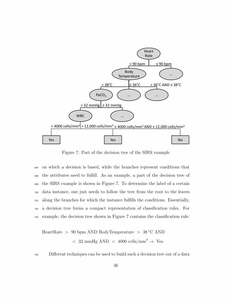
Figure 7: Part of the decision tree of the SIRS example
on which a decision is based, while the branches represent conditions that697
the attributes need to fulfill. As an example, a part of the decision tree of698
the SIRS example is shown in Figure 7. To determine the label of a certain699
data instance, one just needs to follow the tree from the root to the leaves700
along the branches for which the instance fulfills the conditions. Essentially,701
a decision tree forms a compact representation of classification rules. For702
example, the decision tree shown in Figure 7 contains the classification rule:703
HeartRate > 90 bpm AND BodyTemperature > 38 ◦C AND
< 32 mmHg AND < 4000 cells/mm3 → Yes
Different techniques can be used to build such a decision tree out of a data704
36
set, e.g., the Iterative Dichotomiser 3 (ID3) (Quinlan, 1986) or C4.5 (Quinlan,705
1993) algorithm. The latter is a more sophisticated algorithm as it allows706
that attributes have numeric values (Quinlan, 1996), is able to handle missing707
values and prunes the tree in order to make it more compact and avoid708
overfitting (Everitt and Skrondal, 2010).709
To implement the C4.5 decision tree, an external library is used, namely710
WEKA. WEKA provides its own implementation of the C4.5 algorithm,711
namely J4.8, which was used in this research. A subclass of the Fil-712
terInstance abstract class was implemented, called TreeMiner. As pre-713
viously mentioned, WEKA uses the ARFF data format to represent data.714
Therefore, an ARFFDataObject was created as a subclass of DataObject and715
(de)convertors were implemented that are able to translate the internal data716
format of the Learning Engine, i.e., LearningDataObject, to and from the717
ARFF data format. As mentioned in Section 4, it is enough to indicate in718
the TreeMiner that the filter uses the ARFFDataObject in the getDataType719
method and the framework will automatically use the correct (de)convertors720
to transform the data. Which attribute should be used as label can be indi-721
cated in the TreeMiner class. In case the label is not indicated, the TreeM-722
iner assumes that the last attribute in the data format is the label. The723
ARFFInputConvertor, discussed in the previous section, makes sure that the724
last attribute is indeed the label. The doProcessing method then calls the725
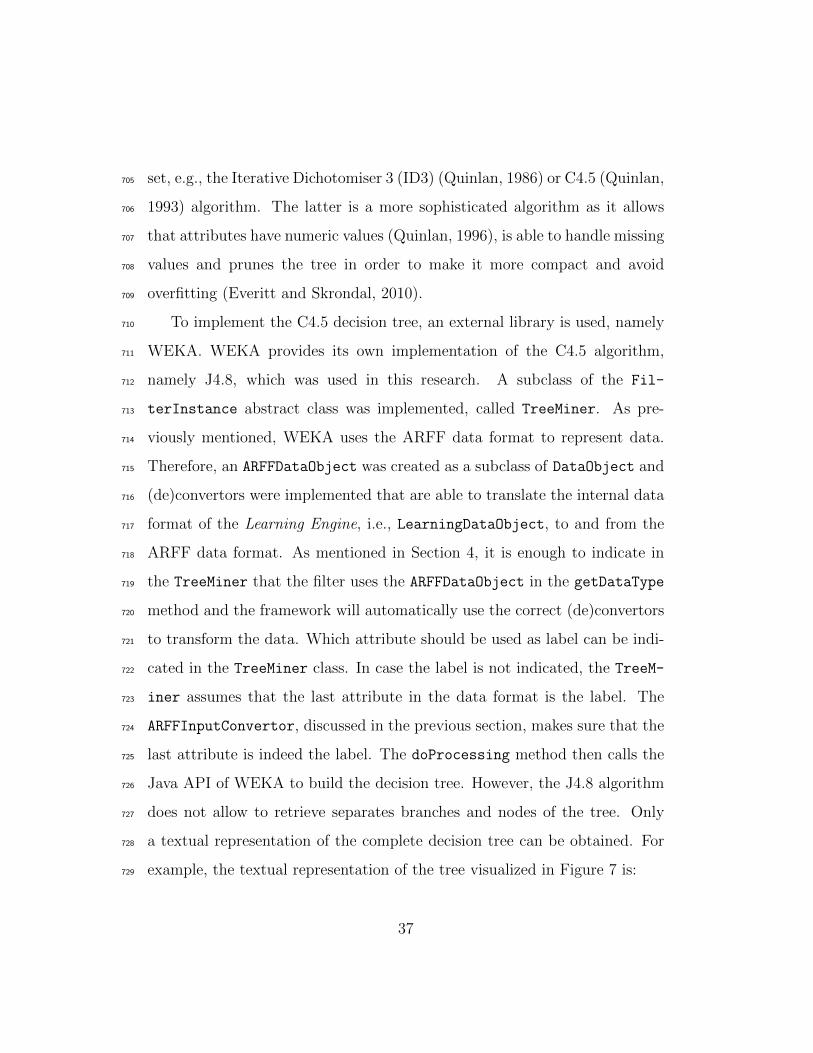
Java API of WEKA to build the decision tree. However, the J4.8 algorithm726
does not allow to retrieve separates branches and nodes of the tree. Only727
a textual representation of the complete decision tree can be obtained. For728
example, the textual representation of the tree visualized in Figure 7 is:729
37

N0 [label=“HeartRate” ]
N0→ N1 [label=“ > 90”]
N1 [label=“BodyTemperature” ]
N1→ N2 [label=“ > 38”]
N2 [label=“PaCO2” ]
N2→ N3 [label=“ < 32”]
N3 [label=“WBC” ]
N3→ N4 [label=“ < 4000”]
N4 [label=“Yes”]
The nodes and branches are identified and translated to the Learning-730
DataObject format such that the result can be forwarded to the next step731
in the pipeline. It is important to note that new results are always added to732
the data being exchanged, so that the original data set also stays available733
for the following steps in the pipeline.734
The Post-Processing filter is responsible for deriving the rules out of the735
textual representation of the decision tree provided by the J4.8 algorithm.736
Therefore, the BooleanRuleExtractor subclass of the FilterInstance class737
was implemented. The implemented doProcessing method takes into ac-738
count that the label has a boolean value, i.e., Yes or No. Only the branches739
that result in a positive leaf need to be translated into a rule, as only those740
rules will result in calls. The doProcessing method starts from a positive741
leaf and follows the branches until the root is reached. Each branch that is742
crossed is added as a condition in the rule. The iterative build-up of the rule743
38
according to the output of the J4.8 algorithm illustrated in Figure 7 is as744
follows:745
Step 1: → Y es
Step 2: WBC < 4000 → Yes
Step 3: PaCO2 < 32 AND WBC < 4000 → Yes
Step 4: BodyTemperature > 38 AND PaCO2 < 32 AND
WBC < 4000 → Yes
Step 5: HeartRate > 90 AND BodyTemperature > 38 AND
PaCO2 < 32 AND WBC < 4000 → Yes
The resulting rules are represented in the LearningDataObject format746
such that they can be processed by the Decision Module.747
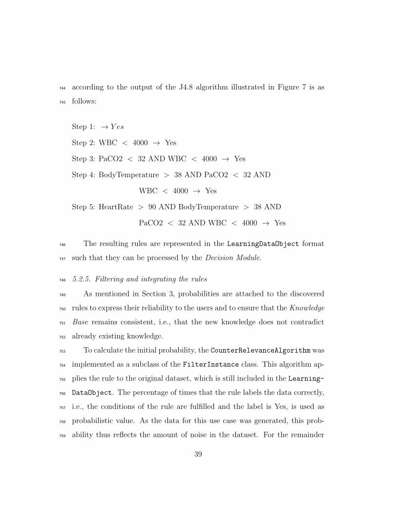
5.2.5. Filtering and integrating the rules748
As mentioned in Section 3, probabilities are attached to the discovered749
rules to express their reliability to the users and to ensure that the Knowledge750
Base remains consistent, i.e., that the new knowledge does not contradict751
already existing knowledge.752
To calculate the initial probability, the CounterRelevanceAlgorithm was753
implemented as a subclass of the FilterInstance class. This algorithm ap-754
plies the rule to the original dataset, which is still included in the Learning-755
DataObject. The percentage of times that the rule labels the data correctly,756
i.e., the conditions of the rule are fulfilled and the label is Yes, is used as757
probabilistic value. As the data for this use case was generated, this prob-758
ability thus reflects the amount of noise in the dataset. For the remainder759
39

of the text, it assumed that the rule, which was presented in the previous760
section, receives a probability of 85%.761
A simple filter algorithm, namely the ThresholdFilterAlgorithm was762
implemented as subclass of the FilterInstance class. This algorithm filters763
the rules for which the probability is lower than a specified probability, e.g.,764
50%. This rule is thus not added to the Knowledge Base. However, the rule765
and its associated probability is archived in the Persistence Layer.766
Finally, the ContextCallIntegrationModule, a subclass of the Inte-767
grationModule class, is responsible for integrating the rules and associated768
probabilities in the Knowledge Base. First, new subclasses of ContextCall769
and Reason are introduced in the ontology, with as name the condition of770
the rule added before the suffix ContextCall and Reason respectively. For771
brevity, SIRSContextCall and SIRSReason are used to refer to the concepts772
that are created for the rule, which is used as running example, i.e., the rule773
that fulfills each of the four criteria. These concepts are visualized in grey in774
Figure 6. Pronto is used to represent and reason on the probabilistic infor-775
mation in the ontology. To express generic probabilistic knowledge, Pronto776
uses Generic Conditional Constraints (GCCs) (Lukasiewicz, 2007). Generic777
means that the knowledge does not apply to any specific individual but rather778
to a fresh, randomly chosen one. A GCC is of the form (D—C)[l,u] where D779
and C are classes in the ontology and [l,u] is a closed subinterval of [0,1]. To780
represent these GCCs in the ontology, Pronto employs subsumption axiom781
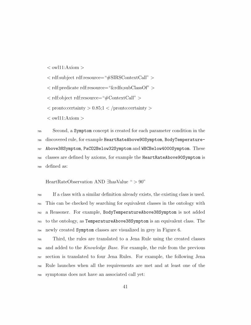
annotations. For example, to express the fact that the SIRSContextCall is782
a ContextCall with only 85% probability, the following subsumption axiom783
annotation is added to the ontology:784
40
< owl11:Axiom >
< rdf:subject rdf:resource=“#SIRSContextCall” >
< rdf:predicate rdf:resource=“&rdfs;subClassOf” >
< rdf:object rdf:resource=“#ContextCall” >
< pronto:certainty > 0.85;1 < /pronto:certainty >
< owl11:Axiom >
Second, a Symptom concept is created for each parameter condition in the785
discovered rule, for example HeartRateAbove90Symptom, BodyTemperature-786
Above38Symptom, PaCO2Below32Symptom and WBCBelow4000Symptom. These787
classes are defined by axioms, for example the HeartRateAbove90Symptom is788
defined as:789
HeartRateObservation AND ∃hasValue “ > 90”
If a class with a similar definition already exists, the existing class is used.790
This can be checked by searching for equivalent classes in the ontology with791
a Reasoner. For example, BodyTemperatureAbove38Symptom is not added792
to the ontology, as TemperatureAbove38Symptom is an equivalent class. The793
newly created Symptom classes are visualized in grey in Figure 6.794
Third, the rules are translated to a Jena Rule using the created classes795
and added to the Knowledge Base. For example, the rule from the previous796
section is translated to four Jena Rules. For example, the following Jena797
Rule launches when all the requirements are met and at least one of the798
symptoms does not have an associated call yet:799
41
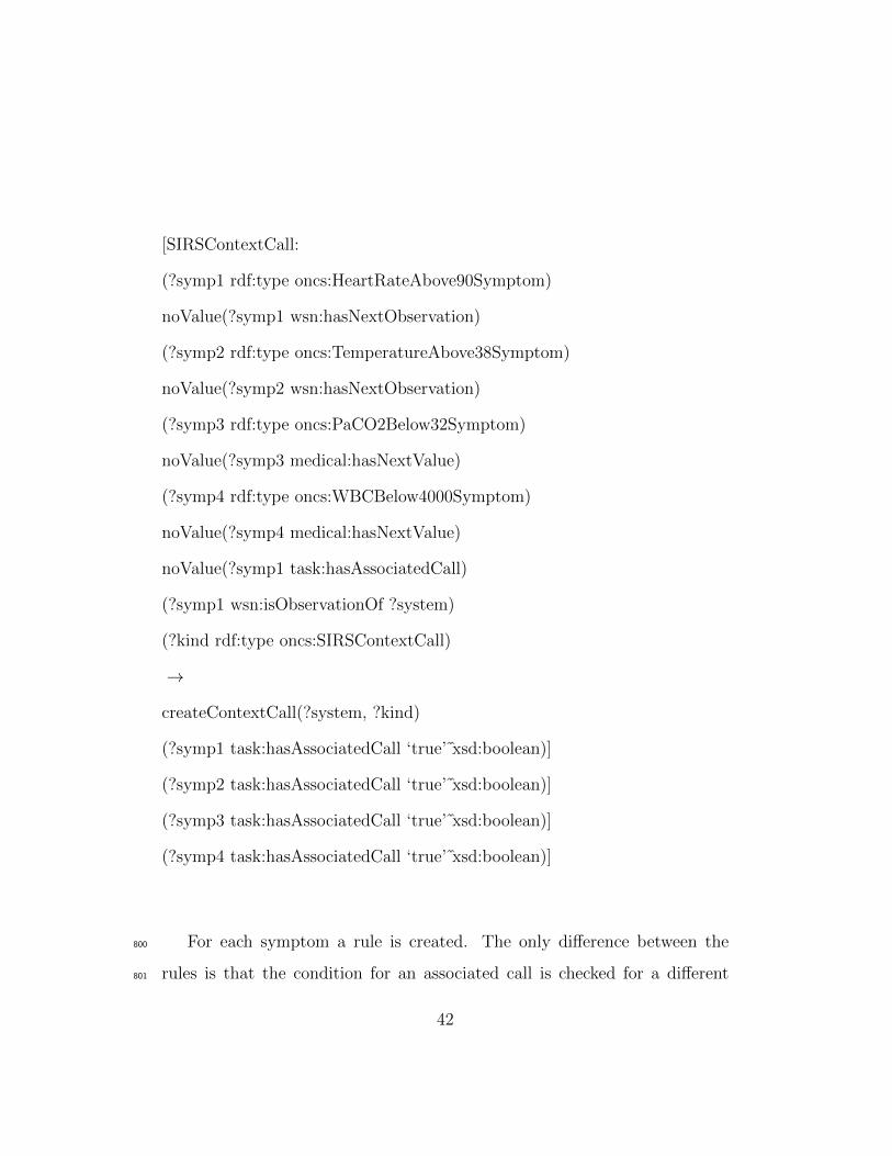
[SIRSContextCall:
(?symp1 rdf:type oncs:HeartRateAbove90Symptom)
noValue(?symp1 wsn:hasNextObservation)
(?symp2 rdf:type oncs:TemperatureAbove38Symptom)
noValue(?symp2 wsn:hasNextObservation)
(?symp3 rdf:type oncs:PaCO2Below32Symptom)
noValue(?symp3 medical:hasNextValue)
(?symp4 rdf:type oncs:WBCBelow4000Symptom)
noValue(?symp4 medical:hasNextValue)
noValue(?symp1 task:hasAssociatedCall)
(?symp1 wsn:isObservationOf ?system)
(?kind rdf:type oncs:SIRSContextCall)
→
createContextCall(?system, ?kind)
(?symp1 task:hasAssociatedCall ‘true’ xsd:boolean)]
(?symp2 task:hasAssociatedCall ‘true’ xsd:boolean)]
(?symp3 task:hasAssociatedCall ‘true’ xsd:boolean)]
(?symp4 task:hasAssociatedCall ‘true’ xsd:boolean)]
For each symptom a rule is created. The only difference between the800
rules is that the condition for an associated call is checked for a different801
42
symptom each time. This is because the different symptoms on their own802
might already have launched context calls for other reasons, e.g., the Temper-803
atureAbove38Symptom might already have launched a FeverContextCall.804
Afterwards, all the symptoms are associated with a call to ensure that only805
one context call is launched. The rule also ensures that the most recent806
parameter values are taken into account by checking whether there are no807
next observations or parameter values through the hasNextObservation and808
hasNextValue relations.809
When the rule is fulfilled, a new context call is added to the Knowledge810
Base. Consequently, the oNCS will detect the new context call and assign811
a staff member to it. The Pronto reasoner can then be used to retrieve the812
probabilistic information associated with the call. This information can then813
be conveyed to the assigned caregiver through the mobile application.814
As only subclasses are added to the ontology and no knowledge is re-815
moved, it is unlikely that the ontology will become inconsistent. However,816
if the ontology does become inconsistent, the following solution can be em-817
ployed. When new information is added to the ontology, the consistency is818
checked. If the ontology is no longer consistent, the information is identified819
with which the new knowledge conflicts. Pronto allows that different chunks820
of probabilistic information conflict with each other. For example, a bird is821
flying object with high probability and all penguins are birds, but a penguin822
has a low probability of flying. More specific probabilistic constraints are thus823
allowed to override more generic ones. The conflicting information is anno-824
tated with the probabilistic interval [1,1], which indicates that the knowledge825
is generally true. Consequently, we are now dealing with conflicting, proba-826
43
bilistic knowledge and the rule of increasing specificity can be employed to827
resolve the conflict. As such, we ensure that the ontology remains consistent.828
Finally, the Integration Module also associates the learned knowledge with829
information about the Learning Engine that created it by using concepts830
from the Learning Ontology. The individuals, which are created to realize831
this goal, are visualized in bold in Figure 2.832
Note that ContextCall, Symptom and Reason concepts and an associated833
probabilistic annotation axiom and Jena Rule are created for each discovered834
rule.835
5.2.6. Adapting the probabilities836
This step was not implemented as it requires the system to be deployed837
such that information about the usage of the new knowledge by the caregivers838
can be acquired. However, it is briefly discussed how this task of adapting839
the probabilities could be realized for this use case.840
A Monitoring Algorithm could be implemented, which takes as parame-841
ter the newly created context call, e.g., in this case SIRSContextCall. The842
algorithm monitors the Knowledge Base and collects calls of this type, which843
have been launched by the system. For each call, its reason and the symp-844
toms that caused the calls to be launched are retrieved. When nurses handle845
calls, they need to input the reason for the call. For context calls, they can846
affirm the reason, which was assigned by the framework, e.g., SIRS. They can847
also choose to change it, e.g., to false because the call was unnecessary. As848
such a dataset is created for each rule, which maps the values of the medical849
parameters on the associated reason. When a representative amount of data850
has been collected, this dataset can be retrieved by the FileDataCollector851
44
and converted by the ARFFInputConvertor. The output can then be pro-852
cessed by a Learning Pipeline consisting of only one filter. This filter is a853
Probabilistic Relevance Algorithm, which simply calculates the percentage of854
calls for each rule for which the reason was not changed. This means that855
caregivers deemed the reason to be correct. This percentage is than given856
to the Integration Module, which adapts the probability for this rule in the857
ontology to this calculated percentage. As explained in Section 3.3.3, if the858
calculated percentage exceeds or falls below the probability thresholds spec-859
ified in the Integration Module, the knowledge is removed from the ontology860
or added as generally accepted knowledge without a probability.861
5.3. Evaluation set-up862
To evaluate the applicability of the framework, it is important to assess863
the correctness of the derived rules. The correctness of the used data mining864
techniques is influenced by the size of the dataset and the amount of noise.865
To assess the influence of the latter, the Learning Pipeline was consecutively866
applied to datasets of the same size, but with an increasing amount of noise.867
The amount of noise is varied from 0% to 50% in steps of 1%. As mentioned in868
Section 5.2.1, a noise percentage of x means that each Non-SIRS Instance has869
x% chance of being associated with a call and vice versa. It is unnecessary to870
increase the noise percentage beyond 50% as a random label is assigned at this871
point and the dataset becomes meaningless. The amount of noise needs to872
be increased in a dataset of realistic size. The WBC and PaCO2 parameters873
are derived by the laboratory by analyzing a blood sample. Consequently,874
it is unlikely that more than two different values for these parameters will875
be generated per patient per day. If we assume that a department contains876
45

on average 30 patients and that we want to wait at most 28 days before we877
run the self-learning framework for the first time, a realistic dataset contains878
1,680 instances, i.e., 30 patients x 28 days x 2 entries per patient per day.879
The influence of the size of the dataset on the correctness is evaluated by880
consecutively applying the Learning Pipeline to datasets of increasing size.881
The dataset sizes range from 100 to 2,000 instances in steps of 100 instances.882
It can be noted that this range also contains the size of the dataset used for883
the correctness tests that evaluate the influence of noise, i.e., 1,680 instances.884
It is also important to evaluate the performance, i.e., execution time and885
memory usage, of the developed Learning Engine. Although, the learning886
process will mostly run in the background, it is important to assess the887
amount of resource usage. Most healthcare environments have a limited888
amount of resources and delegating the processing to the cloud is often dif-889
ficult because of privacy issues. To evaluate the influence of noise on the890
performance, the same datasets were used as for the correctness tests. How-891
ever, to assess the influence of the size of the dataset, datasets were generated892
with sizes ranging from 1,000 to 30,000 in steps of 1,000 instances. Bigger893
datasets were used as it is important to explore the limits of the proposed894
framework.895
To achieve reliable results, each test was repeated 35 times, of which the896
first three and the last two were omitted during processing. For each run,897
a new dataset was generated. Finally, the averages across the 30 remaining898
runs are calculated and visualized in the form of graphs. The tests were899
performed on a computer with the following specifications: 4096 megabyte900
(MB) (2 x 2048 MB) 1067 megahertz (MHz) Double Data Rate Type Three901
46

Synchronous Dynamic Random Access Memory (DDR3 SDRAM) and an902
Intel Core i5-430 Central Processing Unit (CPU) (2 cores, 4 threads, 2.26903
gigahertz (GHz), 3 MB cache).904
The term detection rate is introduced to assess the correctness. The SIRS905
use case is detected when the criteria for each of the four parameters of the906
SIRS use case are discovered. If one or more criteria is not learned, the SIRS907
use case is considered undetected. The detection rate of a dataset with a908
particular size is defined as the percentage of the 30 test runs for this size for909
which the SIRS use case was completely detected. For example, a detection910
rate of 50% for a dataset of 100 instances means that for 15 test runs of this911
dataset size the SIRS criteria were detected.912
To assess the correctness, the relative error of the SIRS criteria is calcu-913
lated. The relative error expresses how much the learned criterion deviates914
from the actual SIRS criterion. For example, a relative error of 5% for the915
“heart rate > 90 ” criterion indicates that the discovered threshold deviates916
from 90 by 5%. Note that the body temperature and WBC parameters have917
both an upper and lower threshold, while the heart rate and PaCO2 have918
only one threshold.919
5.4. Results920
5.4.1. Correctness921
Figure 8 depicts the detection rate as a function of the size of the dataset.922
The detection rate is relatively low for small datasets, but it quickly increases923
and reaches 100% for a dataset with 800 instances. When a dataset contains924
at least 1,000 instances, the detection rate is always 100%.925
The detection rate is off course related to the relative error. In Figure 9926
47
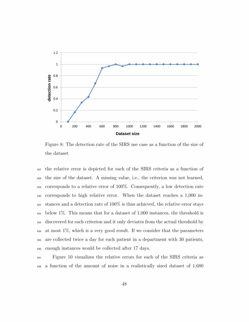
0
0.2
0.4
0.6
0.8
1
1.2
0 200 400 600 800 1000 1200 1400 1600 1800 2000
dete
cti
on
rate
Dataset size
Figure 8: The detection rate of the SIRS use case as a function of the size of
the dataset
the relative error is depicted for each of the SIRS criteria as a function of927
the size of the dataset. A missing value, i.e., the criterion was not learned,928
corresponds to a relative error of 100%. Consequently, a low detection rate929
corresponds to high relative error. When the dataset reaches a 1,000 in-930
stances and a detection rate of 100% is thus achieved, the relative error stays931
below 1%. This means that for a dataset of 1,000 instances, the threshold is932
discovered for each criterion and it only deviates from the actual threshold by933
at most 1%, which is a very good result. If we consider that the parameters934
are collected twice a day for each patient in a department with 30 patients,935
enough instances would be collected after 17 days.936
Figure 10 visualizes the relative errors for each of the SIRS criteria as937
a function of the amount of noise in a realistically sized dataset of 1,680938
48
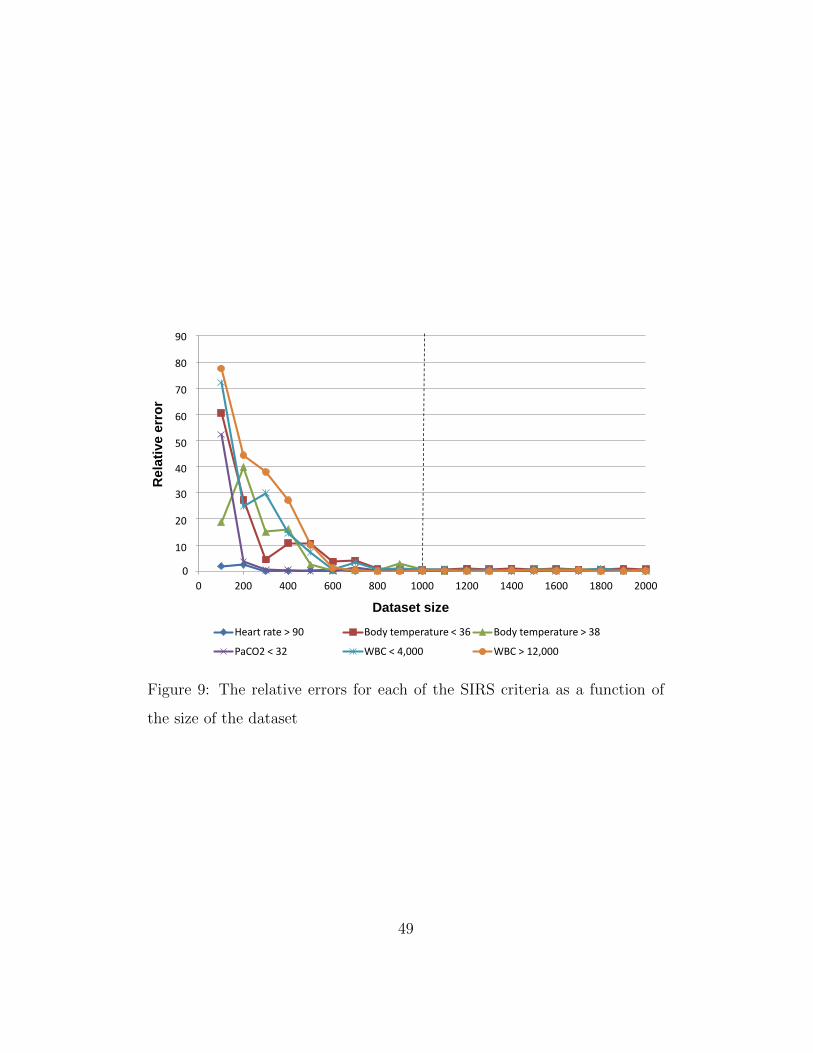
0
0.1
0.2
0.3
0.4
0.5
0.6
0.7
0.8
0.9
0 200 400 600 800 1000 1200 1400 1600 1800 2000
Re
lati
ve
err
or
Dataset size
Heart rate > 90 Body temperature < 36 Body temperature > 38
PaCO2 < 32 WBC < 4,000 WBC > 12,000
90
80
70
60
50
40
30
20
10
Figure 9: The relative errors for each of the SIRS criteria as a function of
the size of the dataset
49
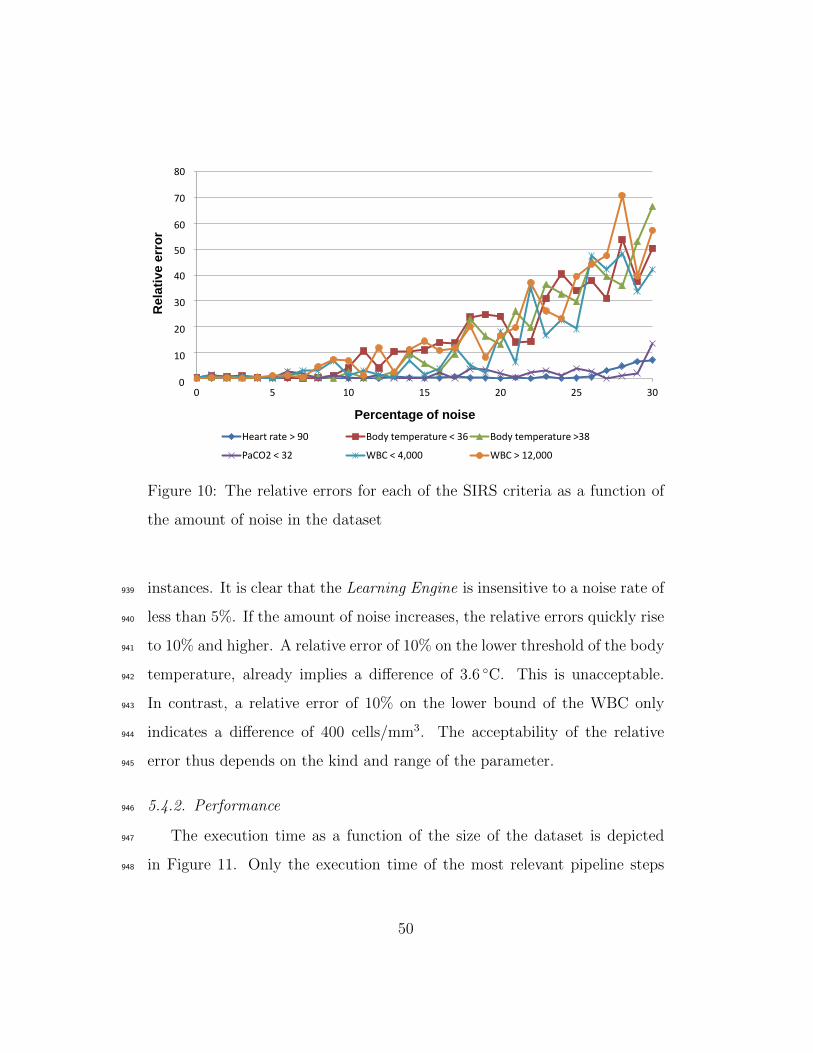
0
0.1
0.2
0.3
0.4
0.5
0.6
0.7
0.8
0 5 10 15 20 25 30
Re
lati
ve
err
or
Percentage of noise
Heart rate > 90 Body temperature < 36 Body temperature >38
PaCO2 < 32 WBC < 4,000 WBC > 12,000
80 70 60
50
40 30 20 10 0
Figure 10: The relative errors for each of the SIRS criteria as a function of
the amount of noise in the dataset
instances. It is clear that the Learning Engine is insensitive to a noise rate of939
less than 5%. If the amount of noise increases, the relative errors quickly rise940
to 10% and higher. A relative error of 10% on the lower threshold of the body941
temperature, already implies a difference of 3.6 ◦C. This is unacceptable.942
In contrast, a relative error of 10% on the lower bound of the WBC only943
indicates a difference of 400 cells/mm3. The acceptability of the relative944
error thus depends on the kind and range of the parameter.945
5.4.2. Performance946
The execution time as a function of the size of the dataset is depicted947
in Figure 11. Only the execution time of the most relevant pipeline steps948
50
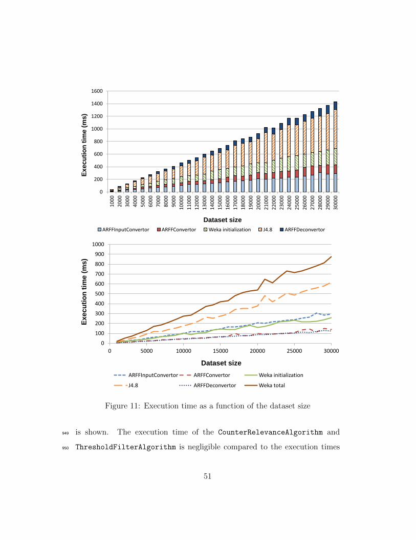
0
200
400
600
800
1000
1200
1400
1600
10
00
20
00
30
00
40
00
50
00
60
00
70
00
80
00
90
00
10
00
0
11
00
0
12
00
0
13
00
0
14
00
0
15
00
0
16
00
0
17
00
0
18
00
0
19
00
0
20
00
0
21
00
0
22
00
0
23
00
0
24
00
0
25
00
0
26
00
0
27
00
0
28
00
0
29
00
0
30
00
0
Ex
ec
uti
on
tim
e (
ms
)
Dataset size
ARFFInputConvertor ARFFConvertor Weka initialization J4.8 ARFFDeconvertor
0
100
200
300
400
500
600
700
800
900
1000
0 5000 10000 15000 20000 25000 30000
Exec
uti
on
tim
e (
ms)
Dataset size
ARFFInputConvertor ARFFConvertor Weka initialization
J4.8 ARFFDeconvertor Weka total
Figure 11: Execution time as a function of the dataset size
is shown. The execution time of the CounterRelevanceAlgorithm and949
ThresholdFilterAlgorithm is negligible compared to the execution times950
51
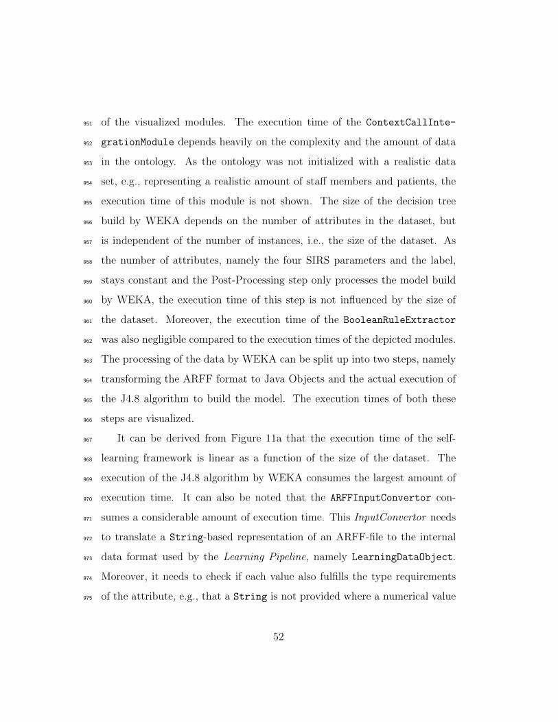
of the visualized modules. The execution time of the ContextCallInte-951
grationModule depends heavily on the complexity and the amount of data952
in the ontology. As the ontology was not initialized with a realistic data953
set, e.g., representing a realistic amount of staff members and patients, the954
execution time of this module is not shown. The size of the decision tree955
build by WEKA depends on the number of attributes in the dataset, but956
is independent of the number of instances, i.e., the size of the dataset. As957
the number of attributes, namely the four SIRS parameters and the label,958
stays constant and the Post-Processing step only processes the model build959
by WEKA, the execution time of this step is not influenced by the size of960
the dataset. Moreover, the execution time of the BooleanRuleExtractor961
was also negligible compared to the execution times of the depicted modules.962
The processing of the data by WEKA can be split up into two steps, namely963
transforming the ARFF format to Java Objects and the actual execution of964
the J4.8 algorithm to build the model. The execution times of both these965
steps are visualized.966
It can be derived from Figure 11a that the execution time of the self-967
learning framework is linear as a function of the size of the dataset. The968
execution of the J4.8 algorithm by WEKA consumes the largest amount of969
execution time. It can also be noted that the ARFFInputConvertor con-970
sumes a considerable amount of execution time. This InputConvertor needs971
to translate a String-based representation of an ARFF-file to the internal972
data format used by the Learning Pipeline, namely LearningDataObject.973
Moreover, it needs to check if each value also fulfills the type requirements974
of the attribute, e.g., that a String is not provided where a numerical value975
52
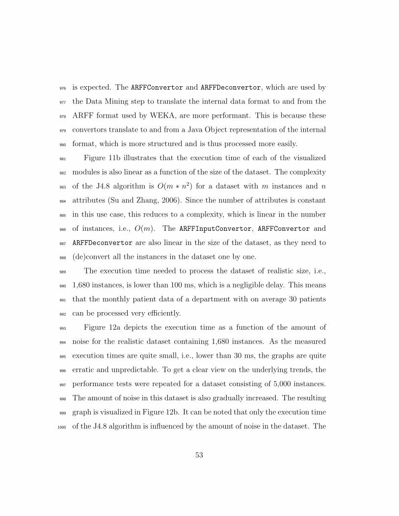
is expected. The ARFFConvertor and ARFFDeconvertor, which are used by976
the Data Mining step to translate the internal data format to and from the977
ARFF format used by WEKA, are more performant. This is because these978
convertors translate to and from a Java Object representation of the internal979
format, which is more structured and is thus processed more easily.980
Figure 11b illustrates that the execution time of each of the visualized981
modules is also linear as a function of the size of the dataset. The complexity982
of the J4.8 algorithm is O(m ∗ n2) for a dataset with m instances and n983
attributes (Su and Zhang, 2006). Since the number of attributes is constant984
in this use case, this reduces to a complexity, which is linear in the number985
of instances, i.e., O(m). The ARFFInputConvertor, ARFFConvertor and986
ARFFDeconvertor are also linear in the size of the dataset, as they need to987
(de)convert all the instances in the dataset one by one.988
The execution time needed to process the dataset of realistic size, i.e.,989
1,680 instances, is lower than 100 ms, which is a negligible delay. This means990
that the monthly patient data of a department with on average 30 patients991
can be processed very efficiently.992
Figure 12a depicts the execution time as a function of the amount of993
noise for the realistic dataset containing 1,680 instances. As the measured994
execution times are quite small, i.e., lower than 30 ms, the graphs are quite995
erratic and unpredictable. To get a clear view on the underlying trends, the996
performance tests were repeated for a dataset consisting of 5,000 instances.997
The amount of noise in this dataset is also gradually increased. The resulting998
graph is visualized in Figure 12b. It can be noted that only the execution time999
of the J4.8 algorithm is influenced by the amount of noise in the dataset. The1000
53
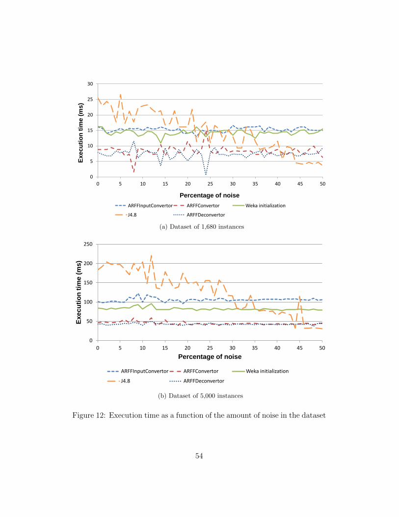
0
5
10
15
20
25
30
0 5 10 15 20 25 30 35 40 45 50
Ex
ec
uti
on
tim
e (
ms
)
Percentage of noise
ARFFInputConvertor ARFFConvertor Weka initialization
J4.8 ARFFDeconvertor
(a) Dataset of 1,680 instances
0
50
100
150
200
250
0 5 10 15 20 25 30 35 40 45 50
Execu
tio
n t
ime (
ms)
Percentage of noise
ARFFInputConvertor ARFFConvertor Weka initialization
J4.8 ARFFDeconvertor
(b) Dataset of 5,000 instances
Figure 12: Execution time as a function of the amount of noise in the dataset
54
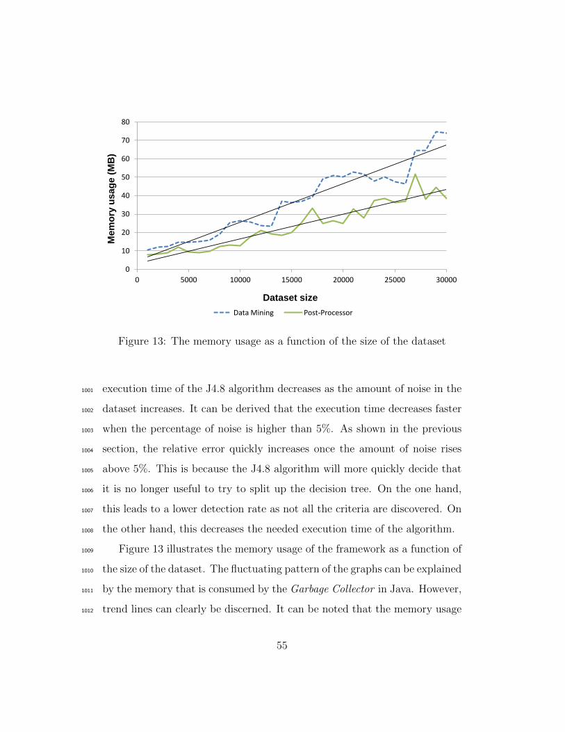
0
10
20
30
40
50
60
70
80
0 5000 10000 15000 20000 25000 30000
Mem
ory
usag
e (
MB
)
Dataset size
Data Mining Post-Processor
Figure 13: The memory usage as a function of the size of the dataset
execution time of the J4.8 algorithm decreases as the amount of noise in the1001
dataset increases. It can be derived that the execution time decreases faster1002
when the percentage of noise is higher than 5%. As shown in the previous1003
section, the relative error quickly increases once the amount of noise rises1004
above 5%. This is because the J4.8 algorithm will more quickly decide that1005
it is no longer useful to try to split up the decision tree. On the one hand,1006
this leads to a lower detection rate as not all the criteria are discovered. On1007
the other hand, this decreases the needed execution time of the algorithm.1008
Figure 13 illustrates the memory usage of the framework as a function of1009
the size of the dataset. The fluctuating pattern of the graphs can be explained1010
by the memory that is consumed by the Garbage Collector in Java. However,1011
trend lines can clearly be discerned. It can be noted that the memory usage1012
55
is linear as a function of the amount of instances. Moreover, the total amount1013
of consumed memory stays quite low, i.e., at most 80 MB. For the realistic1014
dataset of 1,680 instances the memory usage is negligible, namely about 101015
MB.1016
It can be concluded that a dataset of realistic size for the SIRS use case1017
can be processed by any modern PC or server and no cloud-based solutions1018
are needed to run the framework.1019
6. Conclusions1020
In this paper a self-learning, probabilistic, ontology-based framework was1021
presented, which allows context-aware applications to adapt their behavior at1022
run-time. The proposed framework consists of the following steps. First, an1023
ontology-based context model with accompanying rule-based context-aware1024
algorithms is used to capture the behavior of the user and the context in1025
which it is exhibited. Historical information is then gathered by algorithms1026
that identify missing or inaccurate knowledge in the context-aware platform.1027
This historical information is filtered, cleaned and structured so that it can1028
be used as input for data mining techniques. The results of these data min-1029
ing techniques are then prioritized and filtered by associating probabilities,1030
which express how reliable or accurate they are. These results and the asso-1031
ciated probabilities are then integrated into the context model and dynamic1032
algorithms. These probabilities clarify to the stakeholders that this new1033
knowledge has not been confirmed by rigorous evaluation. Finally, these1034
probabilities are adapted, i.e., in- or decreased, according to context and1035
behavioral information gathered about the usage of the learned information.1036
56
The pipeline architecture of the framework was presented and its imple-1037
mentation was detailed. Finally, a representative use case was presented to1038
illustrate the applicability of the framework, namely mining the reasons for1039
patients’ nurse call light use to automatically launch calls. More specifically,1040
detecting SIRS as a reason for nurse calls was used as a realistic scenario to1041
evaluate the correctness and performance of the proposed framework. It is1042
shown that correct results are achieved when the dataset contains at least1043
1,000 instances and the amount of noise is lower than 5%. The execution1044
time and memory usage are also negligible for a realistic dataset, i.e., below1045
100 ms and 10 MB.1046
Future work will mainly focus on the development of more intricate moni-1047
toring, probabilistic relevance and filter algorithms. Moreover, a prototype of1048
the proposed framework will be deployed and evaluated in a real-life setting.1049
Acknowledgements1050
We would like to acknowledge that part of this research was supported by1051
the iMinds Project ACCIO co-funded by the IWT, iMinds and the following1052
partners: Televic NV, Boone NV, Dominiek Savio Instituut and In-Ham.1053
F. Ongenae and M. Claeys would like to thank the IWT for financial support1054
through their Ph.D. grant. The authors thank F. De Backere for support in1055
constructing the figures.1056
References1057
Anderston, J., Aydin, C., 1997. Evaluating the impact of health care infor-1058
mation systems. International Journal Technology Assessment in Health1059
57
Care 13 (2), 380–393.1060
Baader, F., Calvanese, D., McGuinness, D. L., Nardi, D., Patel-Schneider,1061
P., 2003. The Description Logic Handbook: Theory, Implementation and1062
Applications. Cambridge University Press.1063
Baldauf, M., Dustdar, S., Rosenberg, F., 2007. A survey on context-aware1064
systems. International Journal of Ad Hoc and Ubiquitous Computing 2 (4),1065
263–277.1066
Baralis, E., Cagliero, L., Cerquitelli, T., Garza, P., Marchetti, M., 2011.1067
Cas-mine: providing personalized services in context-aware applications1068
by means of generalized rules. Knowledge and Information Systems 28 (2),1069
283–310.1070
Bardram, J., 14-17 March 2004. Applications of context-aware computing1071
in hospital work - Examples and design principles. In: Proceedings of the1072
Annual ACM Symposium on Applied Computing. New York, NY, USA:1073
ACM Press;, Nicosia, Cyprus, pp. 1574–1579.1074
Bass, L., Clements, P., Kazman, R., 2003. Software Architecture in Practice,1075
2nd Edition. Addison-Wesley Professional.1076
Blake, J. A., Harris, M. A., 2008. The Gene Ontology (GO) project: struc-1077
tured vocabularies for molecular biology and their application to genome1078
and expression analysis. Current Protocols in Bioinformatics 23 (7.2.1-1079
7.2.9), 1472–6947, http://www.geneontology.org/.1080
Bricon-Souf, N., Newman, C. R., 2007. Context awareness in health care: A1081
review. International Journal of Medical Informatics 76 (1), 2–12.1082
58
Burgelman, J.-C., Punie, Y., 2006. Close encounters of a different kind: am-1083
bient intelligence in Europe. True Vision: The Emergence of Ambient In-1084
telligence, 19–35.1085
Byun, H., Cheverst, K., 2004. Utilizing context history to provide dynamic1086
adaptations. Applied Artificial Intelligence 18 (6), 533–548.1087
Carroll, J. J., Dickinson, I., Dollin, C., Reynolds, D., Seaborne, A., Wilkin-1088
son, K., May 17–22 2004. Jena: implementing the semantic web recom-1089
mendations. In: Proceedings of the 13th international conference on World1090
Wide Web, Alternate track papers & posters. New York, NY, USA, pp.1091
74–83.1092
Chen, H., 2004. An intelligent broker architecture for pervasive context-aware1093
systems. Ph.D. thesis, University of Maryland, Baltimore County.1094
Chin, T., 2004. Technology valued, but implementing it into practice is1095
slow. American Medical News, http://www.ama-assn.org/amednews/1096
2004/01/19/bisb0119.htm.1097
Colpaert, K., Belleghem, S. V., Benoit, D., Steurbaut, K., Turck, F. D.,1098
Decruyenaere, J., October 11-14 2009. Has information technology finally1099
been adopted in intensive care units? In: 22nd Annual Congress of the1100
European Society of Intensive Care Medicine. Vienna, Austria, p. 235.1101
Criel, J., Claeys, L., 2008. A transdisciplinary study design on context-aware1102
applications and environments. a critical view on user participation within1103
calm computing. Observatorio 2 (2), 57–77.1104
59
Davies, M. G., Hagen, P. O., 1997. Systematic inflammatory response syn-1105
drome. The British Journal of Surgery 84 (7), 920–935.1106
de Toledo, P., Jimenez, S., del Pozo, F., Roca, J., Alonso, A., Hernandez, C.,1107
2006. Telemedicine experience for chronic care in copd. IEEE Transactions1108
on Information Technology in Biomedicine 10 (3), 567–573.1109
Dey, A. K., Abowd, G. D., 1-6 April 2000. Towards a better understanding1110
of context and context-awareness. In: Morse, D. R., Dey, A. K. (Eds.),1111
Proceedings of the CHI Workskhop on the What, Who, Where, When and1112
How of Context-Awareness. New York, NY, USA: ACM Press, The Hague,1113
The Netherlands, pp. 304–307.1114
Everitt, B. S., Skrondal, A., 2010. The Cambridge Dictionary of Statistics,1115
4th Edition. Cambridge University Press, New Yor, USA.1116
Fishkin, K., Wang, M., Fishkin, K. P., Wang, M., 2003. A flexible, low-1117
overhead ubiquitous system for medication monitoring. Tech. rep., Intel1118
Research Seattle, Technical Memo IRS-TR-03-011.1119
Floerkemeier, C., Siegemund, F., 25 October 2003. Improving the effective-1120
ness of medical treatment with pervasive computing technologies. In: Pro-1121
ceedings of the 2nd International Workshop on Ubiquitous Computing for1122
Pervasive Healthcare Applications at International Conference on Ubiqui-1123
tous Intelligence and Computing. Seattle, Washington, USA.1124
Fook, V. F. S., Tay, S. C., Jayachandran, M., Biswas, J., Zhang, D., 13-171125
March 2006. An ontology-based context model in monitoring and handling1126
agitation behaviour for persons with dementia. In: Proceedings of the 4th1127
60
IEEE International Conference on Pervasive Computing and Commununi-1128
cations Workshops (PERCOMW). Washington, DC, USA: IEEE Com-1129
puter Society;, Pisa, Italy, pp. 560–564.1130
Gruber, T., 1993. A translation approach to portable ontology specifications.1131
Knowledge Acquisition 5 (2), 199–220.1132
Gu, T., Pung, H. K., Zhang, D. Q., 2005. A service-oriented middleware for1133
building context-aware services. Journal of Network and Computer Appli-1134
cations (JNCA) 28 (1), 1–18.1135
Hong, J., Suh, E., Kim, S., 2009a. Context-aware systems: A literature1136
review and classification. Expert Systems with Applications 36 (4), 8509–1137
8522.1138
Hong, J., Suh, E.-H., Kim, J., Kim, S., 2009b. Context-aware system for1139
proactive personalized service based on context history. Expert Systems1140
with Applications 36 (4), 7448–7457.1141
Horrocks, I., Patel-Schneider, P. F., Boley, H., Tabet, S., Grosof, B., Dean,1142
M., 2004. SWRL: A semantic web rule language combining OWL and1143
RuleML. Tech. rep., http://www.w3.org/Submission/SWRL/.1144
Hu, B., Hu, B., Wan, J., Dennis, M., Chen, H.-H., Li, L., Zhou, Q., 2010.1145
Ontology-based ubiquitous monitoring and treatment against depression.1146
Wireless Communications & Mobile Computing 10 (10), 1303–1319.1147
Jahnke, J. H., Bychkov, Y., Dahlem, D., Kawasme, L., 2004. Context-aware1148
information services for health care. In: Proc. of the Workshop on Modeling1149
and Retrieval of Context. pp. 73–84.1150
61
Jansen, B., Deklerck, R., November 29 2006. Context aware inactivity recog-1151
nition for visual fall detection. In: Proceedings of the Pervasive Health1152
Conference and Workshops. Innsbruck, Austria, pp. 1–4.1153
Klinov, P., June 1-5 2008. Pronto: A non-monotonic probabilistic descrip-1154
tion logic reasoner. In: Proceedings of the 5th European Semantic Web1155
Conference. Tenerife, Spain, pp. 822–826.1156
Korhonen, I., Paavilainen, P., Sarela, A., 25 October 2003. Application of1157
ubiquitous computing technologies for support of independent living of1158
the elderly in real life settings. In: Proceedings of the 2nd International1159
Workshop on Ubiquitous Computing for Pervasive Healthcare Applications1160
at International Conference on Ubiquitous Intelligence and Computing.1161
Seattle, Washington, USA.1162
Kotsiantis, S. B., 2007. Supervised machine learning: A review of classifica-1163
tion techniques. Informatica 31 (3), 249–268.1164
Kotsiantis, S. B., 2013. Decision trees: a recent overview. Artificial Intelli-1165
gence Review 39 (4), 261–283.1166
Lukasiewicz, T., 2007. Probabilistic description logics for the semantic web.1167
Tech. rep., Technical University of Wien, Institute for Information Sys-1168
tems, Wien, Austria.1169
McGuinness, D. L., Harmelen, F. v., February 10 2004. Owl web ontology1170
language overview. Tech. Rep. REC-owl-features-20040210, World Wide1171
Web Consortium, http://www.w3.org/TR/owl-features/.1172
62
Mihailidis, A., Carmichael, B., Boger, J., Fernie, G., 25 October 2003. An1173
intelligent environment to support aging-in-place, safety, and independence1174
of older adults with dementia. In: Proceedings of the 2nd International1175
Workshop on Ubiquitous Computing for Pervasive Healthcare Applications1176
at International Conference on Ubiquitous Intelligence and Computing.1177
Seattle, Washington, USA.1178
Mitchell, S., Spiteri, M. D., Bates, J., Coulouris, G., 17-20 September 2000.1179
Context-aware multimedia computing in the intelligent hospital. In: Pro-1180
ceedings of the 9th workshop on ACM SIGOPS European workshop: be-1181
yond the PC: new challenges for the operating system. New York, NY,1182
USA: ACM;, Kolding, Denmark, pp. 13–18.1183
Munoz, M. A., Rodrıguez, M., Favela, J., Martinez-Garcia, A. I., Gonzalez,1184
V. M., 2003. Context-aware mobile communication in hospitals. Computer1185
36 (9), 38–46.1186
Nystrom, P. O., 1998. The systemic inflammatory response syndrome: defi-1187
nitions and aetiology. Journal of Antimicrobial Chemotherapy 41, 1–7.1188
O’Connor, M. J., Das, A. K., 2010. A lightweight model for representing and1189
reasoning with temporal information in biomedical ontologies. In: Interna-1190
tional Conference on Health Informatics (HEALTHINF). Valencia, Spain,1191
pp. 90–97.1192
Ongenae, F., Bleumers, L., Sulmon, N., Verstraete, M., Jacobs, A., Van Gils,1193
M., Ackaert, A., De Zutter, S., Verhoeve, P., De Turck, F., 26-29 Octo-1194
ber 2011a. Participatory design of a continuous care ontology: Towards1195
63
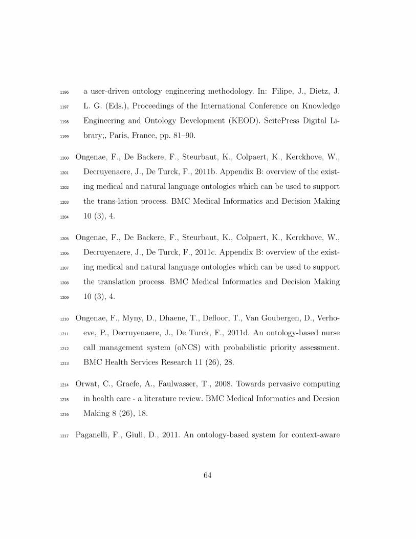
a user-driven ontology engineering methodology. In: Filipe, J., Dietz, J.1196
L. G. (Eds.), Proceedings of the International Conference on Knowledge1197
Engineering and Ontology Development (KEOD). ScitePress Digital Li-1198
brary;, Paris, France, pp. 81–90.1199
Ongenae, F., De Backere, F., Steurbaut, K., Colpaert, K., Kerckhove, W.,1200
Decruyenaere, J., De Turck, F., 2011b. Appendix B: overview of the exist-1201
ing medical and natural language ontologies which can be used to support1202
the trans-lation process. BMC Medical Informatics and Decision Making1203
10 (3), 4.1204
Ongenae, F., De Backere, F., Steurbaut, K., Colpaert, K., Kerckhove, W.,1205
Decruyenaere, J., De Turck, F., 2011c. Appendix B: overview of the exist-1206
ing medical and natural language ontologies which can be used to support1207
the translation process. BMC Medical Informatics and Decision Making1208
10 (3), 4.1209
Ongenae, F., Myny, D., Dhaene, T., Defloor, T., Van Goubergen, D., Verho-1210
eve, P., Decruyenaere, J., De Turck, F., 2011d. An ontology-based nurse1211
call management system (oNCS) with probabilistic priority assessment.1212
BMC Health Services Research 11 (26), 28.1213
Orwat, C., Graefe, A., Faulwasser, T., 2008. Towards pervasive computing1214
in health care - a literature review. BMC Medical Informatics and Decsion1215
Making 8 (26), 18.1216
Paganelli, F., Giuli, D., 2011. An ontology-based system for context-aware1217
64
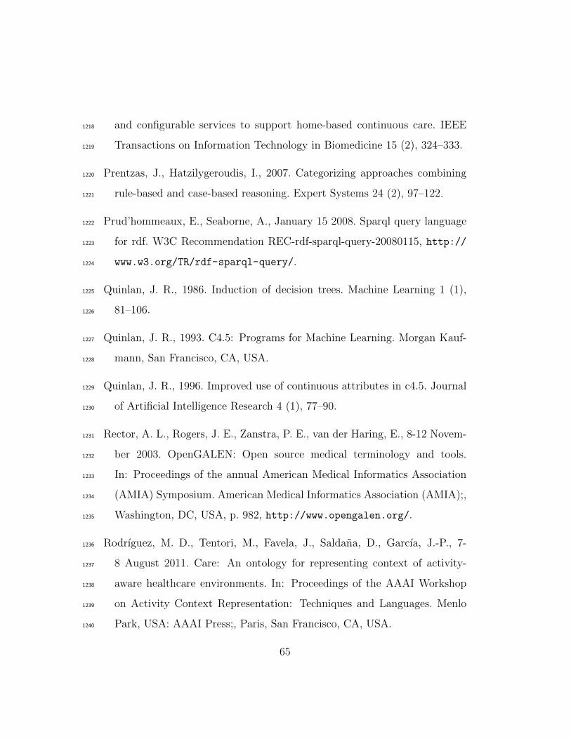
and configurable services to support home-based continuous care. IEEE1218
Transactions on Information Technology in Biomedicine 15 (2), 324–333.1219
Prentzas, J., Hatzilygeroudis, I., 2007. Categorizing approaches combining1220
rule-based and case-based reasoning. Expert Systems 24 (2), 97–122.1221
Prud’hommeaux, E., Seaborne, A., January 15 2008. Sparql query language1222
for rdf. W3C Recommendation REC-rdf-sparql-query-20080115, http://1223
www.w3.org/TR/rdf-sparql-query/.1224
Quinlan, J. R., 1986. Induction of decision trees. Machine Learning 1 (1),1225
81–106.1226
Quinlan, J. R., 1993. C4.5: Programs for Machine Learning. Morgan Kauf-1227
mann, San Francisco, CA, USA.1228
Quinlan, J. R., 1996. Improved use of continuous attributes in c4.5. Journal1229
of Artificial Intelligence Research 4 (1), 77–90.1230
Rector, A. L., Rogers, J. E., Zanstra, P. E., van der Haring, E., 8-12 Novem-1231
ber 2003. OpenGALEN: Open source medical terminology and tools.1232
In: Proceedings of the annual American Medical Informatics Association1233
(AMIA) Symposium. American Medical Informatics Association (AMIA);,1234
Washington, DC, USA, p. 982, http://www.opengalen.org/.1235
Rodrıguez, M. D., Tentori, M., Favela, J., Saldana, D., Garcıa, J.-P., 7-1236
8 August 2011. Care: An ontology for representing context of activity-1237
aware healthcare environments. In: Proceedings of the AAAI Workshop1238
on Activity Context Representation: Techniques and Languages. Menlo1239
Park, USA: AAAI Press;, Paris, San Francisco, CA, USA.1240
65
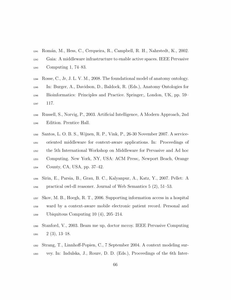
Roman, M., Hess, C., Cerqueira, R., Campbell, R. H., Nahrstedt, K., 2002.1241
Gaia: A middleware infrastructure to enable active spaces. IEEE Pervasive1242
Computing 1, 74–83.1243
Rosse, C., Jr, J. L. V. M., 2008. The foundational model of anatomy ontology.1244
In: Burger, A., Davidson, D., Baldock, R. (Eds.), Anatomy Ontologies for1245
Bioinformatics: Principles and Practice. Springer;, London, UK, pp. 59–1246
117.1247
Russell, S., Norvig, P., 2003. Artificial Intelligence, A Modern Approach, 2nd1248
Edition. Prentice Hall.1249
Santos, L. O. B. S., Wijnen, R. P., Vink, P., 26-30 November 2007. A service-1250
oriented middleware for context-aware applications. In: Proceedings of1251
the 5th International Workshop on Middleware for Pervasive and Ad hoc1252
Computing. New York, NY, USA: ACM Press;, Newport Beach, Orange1253
County, CA, USA, pp. 37–42.1254
Sirin, E., Parsia, B., Grau, B. C., Kalyanpur, A., Katz, Y., 2007. Pellet: A1255
practical owl-dl reasoner. Journal of Web Semantics 5 (2), 51–53.1256
Skov, M. B., Hoegh, R. T., 2006. Supporting information access in a hospital1257
ward by a context-aware mobile electronic patient record. Personal and1258
Ubiquitous Computing 10 (4), 205–214.1259
Stanford, V., 2003. Beam me up, doctor mccoy. IEEE Pervasive Computing1260
2 (3), 13–18.1261
Strang, T., Linnhoff-Popien, C., 7 September 2004. A context modeling sur-1262
vey. In: Indulska, J., Roure, D. D. (Eds.), Proceedings of the 6th Inter-1263
66
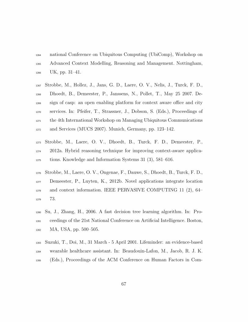
national Conference on Ubiquitous Computing (UbiComp), Workshop on1264
Advanced Context Modelling, Reasoning and Management. Nottingham,1265
UK, pp. 31–41.1266
Strobbe, M., Hollez, J., Jans, G. D., Laere, O. V., Nelis, J., Turck, F. D.,1267
Dhoedt, B., Demeester, P., Janssens, N., Pollet, T., May 25 2007. De-1268
sign of casp: an open enabling platform for context aware office and city1269
services. In: Pfeifer, T., Strassner, J., Dobson, S. (Eds.), Proceedings of1270
the 4th International Workshop on Managing Ubiquitous Communications1271
and Services (MUCS 2007). Munich, Germany, pp. 123–142.1272
Strobbe, M., Laere, O. V., Dhoedt, B., Turck, F. D., Demeester, P.,1273
2012a. Hybrid reasoning technique for improving context-aware applica-1274
tions. Knowledge and Information Systems 31 (3), 581–616.1275
Strobbe, M., Laere, O. V., Ongenae, F., Dauwe, S., Dhoedt, B., Turck, F. D.,1276
Demeester, P., Luyten, K., 2012b. Novel applications integrate location1277
and context information. IEEE PERVASIVE COMPUTING 11 (2), 64–1278
73.1279
Su, J., Zhang, H., 2006. A fast decision tree learning algorithm. In: Pro-1280
ceedings of the 21st National Conference on Artificial Intelligence. Boston,1281
MA, USA, pp. 500–505.1282
Suzuki, T., Doi, M., 31 March - 5 April 2001. Lifeminder: an evidence-based1283
wearable healthcare assistant. In: Beaudouin-Lafon, M., Jacob, R. J. K.1284
(Eds.), Proceedings of the ACM Conference on Human Factors in Com-1285
67
puting Systems. New York, NY, USA: ACM, Seattle, Washington, USA,1286
pp. 127–128.1287
Tentori, M., Segura, D., Favela, J., 2009. Chapter VIII: Monitoring hospi-1288
tal patients using ambient displays. In: Olla, P., Tan, J. (Eds.), Mobile1289
Health Solutions for Biomedical Applications, 1st Edition. Vol. 1. Medical1290
Information Science Reference;, Hershey, New York, USA, pp. 143–158.1291
Tsang, S. L., Clarke, S., 2008. Mining user models for effective adaptation1292
of context-aware applications. International Journal of Security and its1293
Applications 2 (1), 53–62.1294
Valls, A., Gibert, K., Sanchez, D., , Bateta, M., 2010. Using ontologies for1295
structuring organizational knowledge in home care assistance. Internation1296
Journal of Medical Informatics 79 (5), 370–387.1297
Varshney, U., 2009. Chapter 11: Context-awareness in healthcare. In: Perva-1298
sive Healthcare Computing: EMR/EHR, Wireless and Health Monitoring,1299
1st Edition. Springer Science + Business Media, LLC;, New York, NY,1300
USA, pp. 231–257.1301
Verstichel, S., De Poorter, E., De Pauw, T., Becue, P., Volckaert, B., De1302
Turck, F., Moerman, I., Demeester, P., 2010. Distributed ontology-based1303
monitoring on the IBBT WiLab.t infrastructure. In: Proceedings of the1304
6th International Conference on Testbeds and Research Infrastructures1305
for the Development of Networks and Communities (TridentCom). Berlin,1306
Germany, pp. 509–525.1307
68
Witten, I. H., Frank, E., Hall, M., 2011. Data Mining: Practical Machine1308
Learning Tools and Techniques, 3rd Edition. Morgan-Kaufmann.1309
Xue, W., Pung, H. K., 2012. Chapter 8: Context-Aware middleware for1310
supporting mobile applications and services. In: Kamur, A., Xie, B.1311
(Eds.), Handbook of Mobile Systems Applications and Services, 1st Edi-1312
tion. Vol. 1. CRC Press;, Florida, USA, pp. 269–304.1313
Yilmaz, O., Erdur, R. C., 2012. iconawa - an intelligent context-aware system.1314
Expert Systems with Applications 39 (3), 2907–2918.1315
Zhang, D., Yu, Z., Chin, C.-Y., 2005. Context-aware infrastructure for per-1316
sonalized healthcare. Studies in Health Technology and Informatics 117,1317
154–163.1318
69


