
A TUTORIAL ON THE FUNTIONALITY
ON CORE NETWORK MOBILITY
by
JATINDER JASBIR SINGH
Presented to the Faculty of the Graduate School of
The University of Texas at Arlington in Partial Fulfillment
of the Requirements
for the Degree of
MASTER OF SCIENCE IN ELECTRICAL ENGINEERING
THE UNIVERSITY OF TEXAS AT ARLINGTON
DECEMBER 2010

Copyright © by Jatinder Jasbir Singh 2010
All Rights Reserved

iii
ACKNOWLEDGEMENTS
The writing of this thesis has been one of the most significant academic challenges I
have ever had to face. Without the support, patience and guidance of the following people, this
study would not have been completed. It is to them that I owe my deepest gratitude. Dr.
Stephen Ralph Gibbs who undertook to act as my supervisor despite his many other academic
and professional commitments, his wisdom, knowledge and commitment to the highest
standards inspired and motivated me. My friends and colleagues Prashant Srivastava, Dhruv
Shah, Ayush Maheshwari, and Amay Umradia, who inspired my final effort despite the
enormous work pressures we were facing together. Jasbir Singh Saini and Anand Kaur Saini,
my parents, who have always supported, encouraged and believed in me, in all my endeavors.
November 19, 2010

iv
ABSTRACT
A TUTORIAL ON THE FUNCTIONALITY
ON CORE NETWORK MOBILITY
Jatinder Jasbir Singh, M.S.
The University of Texas at Arlington, 2010
Supervising Professor: Ralph Stephen Gibbs
Long Term Evolution (LTE) is next generation Mobile Broadband Technology, which
promises to offer significantly higher data rates, better quality, and more economical. Many of
the service providers are planning to offer this service by 2010-2012. LTE is vast change in the
telecommunication industry from circuit switched network to packet switched network and now
all IP-network. In the fast changing mobile telecommunications seamless handover is important
for any technology to succeed. It is desirable and beneficial from operator as well as user
perspective to have seamless handover with cost effectiveness, enhanced features, and
location independence not only in the case of Intra LTE network but also with the legacy
networks like UMTS, GSM and CDMA that is Inter-RAT handovers.
This tutorial introduces the evolution of the system and then focuses on the Evolved
Packet Core, then it explains various core mobility supporting states and entities. From chapter
4 it explains in detail Intra EPC mobility like initial attach, tracking area procedures, detach
procedures initiated by different entities in the core network. Finally in chapter 5 it explains in
detail the Inter-RAT handovers like from E-UTRAN to UTRAN, UTRAN to E-UTRAN, E-UTRAN
to GERAN, and GERAN to E-UTRAN.

v
TABLE OF CONTENTS
ACKNOWLEDGEMENTS ................................................................................................................iii ABSTRACT ..................................................................................................................................... iv LIST OF ILLUSTRATIONS.............................................................................................................. ix LIST OF ABBREVIATIONS ............................................................................................................. xi Chapter Page
1. INTRODUCTION……………………………………..………..….. ..................................... 1
1.1 Mobile Broadband ............................................................................................ 1
2. EVOLVED PACKET SYSTEM ....................................................................................... 3
2.1 EPS Architecture Layout .................................................................................. 3
2.1.1 Bridging Radio Access networks to EPC ......................................... 4
2.1.1.1 Mobile radio networks/ Cellular Networks ........................ 5 2.1.1.2 Functionality of the Radio Networks ................................ 8 2.1.1.3 Overview of Global System of Mobile ............................ 10 2.1.1.4 Overview of WCDMA ..................................................... 11 2.1.1.5 Overview of LTE ............................................................. 12
3. EVOLVED PACKET CORE ......................................................................................... 16
3.1 Introduction..................................................................................................... 16
3.1.1 GSM core network used for WCDMA/HSPA ................................. 19
3.1.2 WCMA/HSPA connected to EPC ................................................... 20 3.1.3 The Roaming Architecture ............................................................. 21
3.2 EPS Mobility Management and connection Management states .................. 24
3.2.1 Definition of States ......................................................................... 25
3.2.1.1 EMM-DEREGISTERED ................................................. 25

vi
3.2.1.2 EMM-REGISTERED ...................................................... 25
3.2.1.3 ECM-IDLE ...................................................................... 25 3.2.1.4 ECM-CONNECTED ....................................................... 26
3.2.2 Transitions of States ...................................................................... 26
3.3 Traffic Management in MME .......................................................................... 27
3.3.1 Load balancing between MMEs ..................................................... 27
3.3.2 Load rebalancing between MMEs .................................................. 28
3.3.3 MME control of Overload ............................................................... 28 3.4 Policy Charging and Control (PCC) architecture ........................................... 29
3.4.1 Reference Architecture .................................................................. 29
3.4.2 Reference Points ............................................................................ 32
3.4.2.1 Rx reference point .......................................................... 32 3.4.2.2 Gx reference point.......................................................... 33 3.4.2.3 Sp reference point .......................................................... 33 3.4.2.4 Gy reference point.......................................................... 33
3.4.2.5 Gz reference point.......................................................... 33
3.4.2.6 S9 reference point .......................................................... 33
3.4.2.7 Gxx reference point ........................................................ 33
4. AUTHENTICATION AND MOBILITY MANAGEMENT ................................................ 36
4.1 Attach/Track/Detach procedure ..................................................................... 36
4.1.1 E-UTRAN Initial Attach ................................................................... 36 4.1.2 E-UTRAN Tracking Area Update Procedures................................ 45
4.1.2.1 Tracking Area Update with SGW change ...................... 45 4.1.2.2 Tracking Area Update without SGW change ................. 50
4.1.3 Service Request Procedures ......................................................... 55
4.1.3.1 UE triggered Service Request ....................................... 55

vii
4.1.3.2 Network triggered Service Request ............................... 57
4.1.4 Detach Procedure .......................................................................... 58
4.1.4.1 UE initiated Detach Procedure ....................................... 59
4.1.4.1.1 Case when UE is connected to E-UTRAN ..... 59 4.1.4.1.2 Case when UE is connected to GERAN/UTRAN with ISR Activated .............................. 61
4.1.4.2 MME initiated Detach Procedure ................................... 63 4.1.4.3 SGSN initiated Detach Procedure with ISR Activated ... 65 4.1.4.4 HSS initiated Detach Procedure .................................... 67
4.2 TCP Performance Analysis ............................................................................ 68
5. HANDOVERS ............................................................................................................... 73
5.1 E-UTRAN to UTRAN Inter Rat handover ....................................................... 75
5.1.1 Preparation Phase ......................................................................... 75 5.1.2 Execution Phase ............................................................................ 78 5.1.3 Reject Phase .................................................................................. 81
5.2 UTRAN to E-UTRAN Inter Rat handover ....................................................... 84
5.2.1 Preparation Phase ......................................................................... 84 5.2.2 Execution Phase ............................................................................ 87 5.2.3 Reject Phase .................................................................................. 90
5.3 E-UTRAN to GERAN Inter Rat handover ...................................................... 92
5.3.1 Preparation Phase ......................................................................... 92 5.3.2 Execution Phase ............................................................................ 95 5.3.3 Reject Phase .................................................................................. 99
5.4 GERAN to E-UTRAN Inter Rat handover .................................................... 101
5.4.1 Preparation Phase ....................................................................... 101 5.4.2 Execution Phase .......................................................................... 104 5.4.3 Reject Phase ................................................................................ 107

viii
6. CONCLUSION ........................................................................................................... 110
REFERENCES ............................................................................................................................. 111 BIOGRAPHICAL INFORMATION ................................................................................................ 113

ix
LIST OF ILLUSTRATIONS
Figure Page 2.1 3GPP architecture domains ....................................................................................................... 3 2.2 Frequency Reuse ....................................................................................................................... 6 2.3 Determining Cluster Size............................................................................................................ 7 2.4 Connection of the LTE radio access network to core network ................................................. 13 3.1 Basic Structure of EPC............................................................................................................. 16 3.2 CDMA/HSPA core network ...................................................................................................... 19 3.3 WCDMA/HSPA connected to EPC .......................................................................................... 21 3.4 Roaming architecture with home routed traffic ........................................................................ 22 3.5 Roaming architecture with local break through traffic .............................................................. 23 3.6 Roaming in LTE/EPC ............................................................................................................... 23 3.7 EMM and ECM state transitions in the MME ........................................................................... 26 3.8 EMM and ECM state transitions in the UE ............................................................................... 27 3.9 Overall PCC logical Architecture (non roaming) ...................................................................... 30 3.10 Overall PCC Architecture (roaming with home routed access) ............................................. 31 3.11 Overall PCC architecture for roaming with OCEF in visited network (local breakout) ........... 32 4.1 E-UTRAN initial Attach Procedure ........................................................................................... 37 4.2 Tracking area update procedure with SGW change ................................................................ 45 4.3 Tracking Area Update without Serving GW change ................................................................ 50 4.4 UE triggered Service ................................................................................................................ 55 4.5 Network Triggered Service Request ........................................................................................ 57 4.6 UE Initiated detach Procedure with E-UTRAN ......................................................................... 59

x
4.7 UE Initiated Detach Procedure when UE is connected to GERAN/UTRAN with ISR activated ................................................................. 61 4.8 MME Initiated Detach Procedure ............................................................................................. 63 4.9 SGSN initiated detach procedure with ISR mode .................................................................... 65 4.10 HSS-initiated Detach Procedure ............................................................................................ 67 4.11 Without eNodeB reordering .................................................................................................... 71 4.12 With eNodeB reordering ......................................................................................................... 71 4.13 TCP throughput with/without reordering................................................................................. 72 5.1 E-UTRAN to UTRAN preparation phase .................................................................................. 75 5.2 E-UTRAN to UTRAN Execution phase .................................................................................... 78 5.3 Inter RAT handover Reject ....................................................................................................... 81 5.4 UTRAN to E-UTRAN Preparation Phase ................................................................................. 84 5.5 UTRAN to E-UTRAN Execution phase .................................................................................... 87 5.6 UTRAN to E-UTRAN Reject phase .......................................................................................... 90 5.7 E-UTRAN to GERAN Preparation Phase................................................................................. 92 5.8 E-UTRAN to GERAN Execution Phase ................................................................................... 95 5.9 E-UTRAN to GERAN Reject Phase ......................................................................................... 99 5.10 GERAN to E-UTRAN Preparation phase ............................................................................. 101 5.11 GERAN to E-UTRAN Execution Phase ............................................................................... 104 5.12 GERAN to E-UTRAN Reject Phase ..................................................................................... 107

xi
LIST OF ABBREVIATIONS
3GPP = 3rd Generation Partnership Project
AMBR = Aggregate Maximum Bit Rate
AMPS = Analog Mobile Phone System
APN = Access Point Name
ARQ = Automatic Repeat Request
AuC = Authentication Center
BBERF = Bearer Binding and Event Reporting Function
BER = Bit Error Rate
BSS = Base Station System
CDMA = Code Division Multiple Access
CSG = Closed Subscriber Group
ECGI = E-UTRAN Cell Global Identifier
ECM = EPC Connection Management
EIR = Equipment Identity Register
EMM = EPC Mobility Management
EPC = Evolved Packet Core
EPS = Evolved Packet System
ESM = EPS Session Management
E-UTRAN = Evolved UMTS Terrestrial Radio Access Network
FDMA = Frequency Division Multiple Access
FEC = Forward Error Correction
GBR = Guaranteed Bit Rate
GERAN = GSM EDGE Radio Access Network
GSM = Global System of Mobile
GTP = GPRS Tunneling Protocol
GUMMEI = Globally Unique MME Identification
GUTI = Globally Unique Temporary Identification
HLR = Home Location Register
HOM = Higher Order Modulation
HSPA = High Speed Packet Access Network
HSS = Home Subscriber Server
IMEI = International Mobile Equipment Identity
ISR = Idle state Signaling Reduction
LAC = Location Area Code

xii
LTE = Long Term Evolution
MBR = Maximum Bit Rate
MCC = Mobile Country Code
ME = Mobile Equipment
MIMO = Multiple Input Multiple Output
MME = Mobility Management Entity
MMEI = MME Identification
MNC = Mobile Country Code
MSISDN = Mobile Subscriber ISDN Number
NAS = Non Access Stratum
OFDM = Orthogonal Frequency Division Multiplexing
PCC = Policy and Control and Charging
PCEF = Policy and Charging Enforcement Function
PCRF = Policy and Charging Rules Function
PDN = Packet Data Network
PDNGW = PDN Gate Way
PDU = Packet Data Unit
QCI = QoS Class Identifier
RAN = Radio Access Network
RNC = Radio Network Control
RRC = Radio Resources Control
SAE = System Architecture Evolution SC-FDMA = Single Carrier Frequency Multiplexing Access
SDF = Service Data Flow
SGSN = Serving GPRS Support Node
SGW = Serving Gate Way
SPR = Subscription Profile Repository
STBC = Space Time Block Coding
STTC = Space Time Trellis Coding
TAI = Tracking Area Identity
TAU = Tracking Area Update
TEID = Tunnel Endpoint Identifier
UE = User Equipment
UMTS = Universal Mobile Telecommunications System
UTRAN = UMTS Terrestrial Radio Access Network

1
CHAPTER 1
INTRODUCTION
1.1 Mobile Broadband
Since several decades’ telephony or telecommunication system has under gone several
changes, in other words there have been several stages of development as compared to
present working system. Telephony basically started with the aim of voice communication
between two persons, later this system developed in all the aspects either physical or system
level. Telephones sincerely became smaller in their physical size and the system from static
telephone went to mobile/wireless telephone. Bell Labs of USA developed a concept of cells in
1947, this cells based system concept increased the capacity of mobile communications
network by dividing the complete coverage area into smaller cells with each of one having its
own base station operating at different frequencies.
In 1980s the mobile communications saw a huge commercial growth which was called as ‘First
Generation’ systems, in America this system was known as AMPS (Analog Mobile Phone
System), using analog technology. Further development in wireless communication came in the
face of ‘Second Generation’ which was capable of global roaming, this second generation was
known as GSM (Global System for Mobile Communications). The GSM was based on circuit
switching technology and was most successful system in the wireless communication systems,
becoming a robust, interoperable and widely-acceptable standard. As the usage of internet
came into communication world soon the demand for mobile internet increased. The wireless
telecommunication system came under radical change and met internet, this was one of the
major step in the telecomm world it merged the voice and data communications in one system
and became most valuable thing in the daily life for every user. The primary such service was
limited with various reasons like less processing capacity of terminals and limited bandwidth on
2
the radio interface. These limitations became more severe since the demand and hunger of the
bandwidth and high processing rate started increasing tremendously by every passing year.
This hunger and demand is satisfied with the evolution of radio access networks with the high
data rates delivered by High Speed Packet Access and Long Term Evolution systems. Since
several decades the mobile telephony worked on circuit switching technique, but there was a
very fundamental shift which promised to give high data rates with good voice quality and less
latency time and to be most promising mobile network system. This change is from circuit
switched system towards all Internet Protocol (IP) network architecture.
3
CHAPTER 2
EVOLVED PACKET SYSTEM
2.1 EPS Architecture Layout
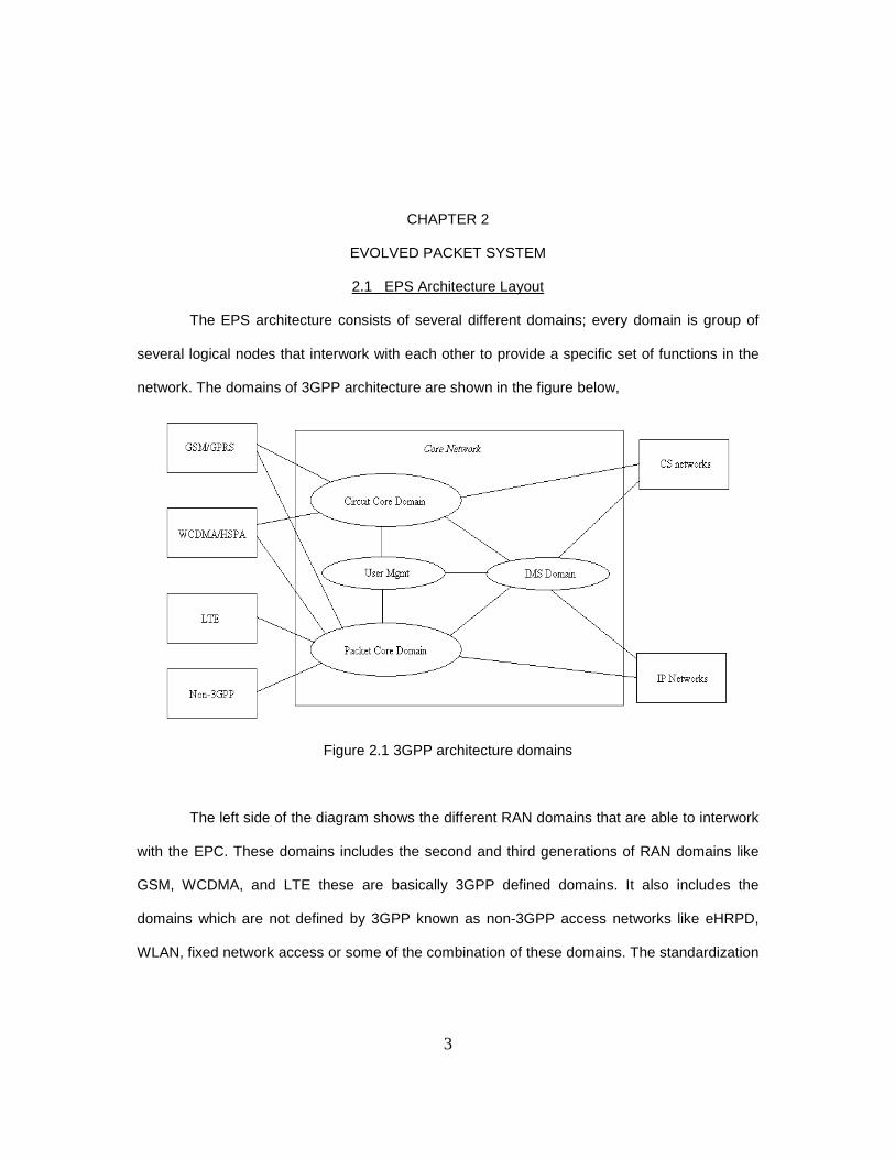
The EPS architecture consists of several different domains; every domain is group of
several logical nodes that interwork with each other to provide a specific set of functions in the
network. The domains of 3GPP architecture are shown in the figure below,
Figure 2.1 3GPP architecture domains
The left side of the diagram shows the different RAN domains that are able to interwork
with the EPC. These domains includes the second and third generations of RAN domains like
GSM, WCDMA, and LTE these are basically 3GPP defined domains. It also includes the
domains which are not defined by 3GPP known as non-3GPP access networks like eHRPD,
WLAN, fixed network access or some of the combination of these domains. The standardization

4
process for these non-3GPP access networks are handled by standardization for a like
3GPP2, IEEE or Broadband Forum.
The Core Network as shown in the figure 2.1 is divided into several domains like circuit
core domain, packet core domain, user management, and IMS domain. The circuit core domain
provides the support for network access like GSM and WCDMA type circuit switched services.
The packet core domain handles the IP connectivity for the services like GSM, WCDMA, and
HSPA. The access networks packet core domain also support management type functions like
user management and policy and law enforcement in the access networks. The IMS domain
supports the multimedia sessions based on Session Initiated Protocol, which uses the packet
core domain function for the IP connectivity.
The term system architecture describes the allocation of necessary functions to logical
notes and the required interfaces between the nodes. The services: charging is needed for the
operator to charge a user; authentication is needed to ensure that the user is valid user; service
setup is needed to ensure that there is end to end connection; etc. These functions are not
directly related to the radio access network instead these functions are called as core functions
and are handled by the Core Network. System architecture is basically divided in two different
parts namely Radio Access Network and Core Network.
2.1.1. Bridging Radio Access networks to EPC
For WCDMA/HSPA, the philosophy behind the functionality split is to keep the core
network unaware of the radio access technology and its layout. In GSM architecture the core
network had the full visibility in the radio access network i.e. the cells in the system, thus when
adding a new cell or removing a cell the core network is needed to be updated. Retransmission
protocols and data buffers were placed in the core network of the GSM, while in the case of
WCDMA/HSPA since the retransmission protocols were used for radio access technology so
they were placed in radio access network instead of the core network.
RAN function includes:

5
• Coding, interleaving, modulation, and other typical physical layer functions.
• ARQ, header compression, and other typical link layer functions.
• Radio Resource Management, handover and other typical radio resource functions.
• Security functions (ciphering and integrity protection).
CN function for LTE includes:
• Charging
• Subscriber management
• Mobility management (keeping track of users roaming around in the network and in
other networks)
• Bearer management and quality of service handling
• Policy control of user data flows
• Interconnection to external networks.
2.1.1.1 Mobile radio networks/ Cellular Networks
Base stations play one the prime role in any radio access network or cellular network,
each of them serve the reception and transmission of the wireless information signals in the
cells covered by each one. Basic cellular structure comprises of three cells for one base station.
The number of cells covered by a single base station depends on the network designing, and
geographical locations the network is serving.
The terminal power of the base station, frequency bands used to propagate signals,
and antenna configurations are among the factors which controls the size of each cell. Apart
from them the environment in which the radio waves are propagating, the geographical
locations like natural walls like mountains, hills, or forests will see more attenuation of signal as
compared to the plains or fairly flat. Signal attenuation is seen more in the downtown of the big
cities because of the presence of the tall buildings as compared to the country side of the cities.
In order to improve the efficiency of the networks various schemes are used one of the
basic technique is named frequency reuse. In frequency reuse the same frequency is used in

6
multiple cells. It is made sure that the cells using same frequency never come in contact with
each other; one of the reuse techniques is shown in the figure below,
Figure 2.2 Frequency Reuse
When numbers of cells are grouped together they form a cluster. Each cluster serves
the complete set of frequencies ranging from the entire allocated spectrum of the operator. In
order to cover the complete coverage area of the operator it repeats this cluster throughout the
coverage area. These cluster patter are derived by formula, N = i2 + ij + j2. Most common
configuration used is of 7-cell cluster. In the formula shown above I and j are depicted in the
diagram below,

7
Figure 2.3 Determining Cluster Size [25]
The above shown formula to calculate the cluster size is very general, but in order to
have more accurate cluster size the following formula is used by the engineers for planning the
cluster size,
Where, C is desired carrier power
Ii is signal power of the interferes
R is the radius of cells
Di is the frequency reuse distance. [25]
While this frequency reuse distance is calculated by the formula, D = SQRT [3C]. [26]
Now since the frequency can be re used in multiple cells it means the total network capacity is
greatly increased. However the functionality to use same frequency in the adjacent channels is
present. The size of the cell is determined by careful observation of the number of users in the
particular cell or area. If the cell is in city downtown then more base stations are required to
handle the traffic, on the other hand if it’s the country side less number of base stations can
easily handle the traffic as compared to other scenario. So the cell size in the city downtown will

8
be smaller than the size of cell in the country side where the number of users is fairly below.
Smaller cell size does also mean more handoffs and hand on, so a careful study is done by
network engineers to carefully determine the exact position of the base stations to optimize the
better performance of the cellular network.
The GSM and WCDMA radio networks the base stations are connected to radio
network backhaul network, unlike in LTE the base stations are supposed to perform all the radio
network functions on its own with the help of the core network. The base stations in LTE are
known as eNodeBs, these eNodeBs handle all the functions related to the radio network, these
functions are discussed in detail in the later part of the report. Since the basic idea of the LTE
architecture was to have fewer nodes as possible so the designers instead of creating more
nodes in radio network developed a complex single node eNodeB to handle the complete radio
network for the LTE systems.
2.1.1.2 Functionality of the Radio Networks
All the three radio technologies by 3GPP share the common fundamental functionality if
the radio network.
Wireless transmission of the data or in other words transmitting and receiving of the
data over wireless channel is the prime feature of the radio networks. The performance of any
radio network depends on the several factors like the distance from the transmitter, frequency
which is used, if the receiver unit is stationary or mobile, transmissions power used by the base
stations and the mobile equipment, height of the base station, geographical location in the
plains or in hilly region, and so on.
Modulating and demodulating the information signal over radio carriers is also
fundamental feature of any wireless radio network either analog or digital. Analog systems are
obviously being replaced by the digital systems because of the advantages in digital systems
over the analog systems. In digital systems the flow of bits are related to the specific service
9
that is being used or provided like voice or video which have different requirements of the bits
flow also.
In case of multiple users the scheduling of the data transmission like buffering or
queuing techniques are used to provide information transmission when the radio channel is free
for the transmission, these techniques also includes different priorities in the queue according to
the QoS to applied for the particular transmission or user. There are various different algorithms
proposed by engineers for the better transmission techniques are still being improved as the
number are users are increasing every second.
Error detection and error correction are techniques that determine in any transmitted
data the bits in error are as low as possible to perform correct information or data transfer from
source to the destination. FEC is abbreviation for Forward Error Correction and ARQ for
Automatic Repeat reQuest are two main error correction and detection techniques which are
used in the real world cellular networks for proper transmission of the data. In the FEC
technique some extra bits known as redundancy bits are added to the information bits, these
redundancy bits helps in detection as well as correction of the one or multiple bits in error. In
ARQ the received bits are checked with the help of the checksum to detect bits in error, if large
group of bits are found in error then the receiver requests the transmitter or sender to resend
the data. In real world of telecommunication both the FEC and ARQ are combined to give better
performance of the radio channels. The smaller errors can be corrected by the FEC while the
larger errors can be taken care of by using the retransmission technique by ARQ. Adaptive
coding schemes are also being deployed by the radio communication systems which decreases
the BER abbreviation for Bits in Error, some of the classic examples of these coding schemes
are Space Time Block Coding (STBC), Space Time Trellis Coding (STTC), Convolution Coding,
Walsh Codes, and so on.
Idle Mode allows the terminals to save the battery power by giving the terminal merit of
not contacting terminal when not using any service either uploading or downloading of any data
10
from the network. In this mode the terminal can move freely in the coverage area specified by
the network without contacting the network and can be mobile in larger geographical area and
saves a huge amount of the battery power at user equipment side. In case of the service
triggered either by network or by the terminal itself it is asked to reconnect the network and give
the complete location information. In the case of network triggered service (in case of incoming
call) the terminal is paged at broadcasting channel and is asked to re attach the network, in the
case of terminal initiated service (outgoing call) the terminal connects to the nearest base
station and provides the information of its last connected base station and updates its location
as to in which cell it is preset. These all attach and detach procedures are explained in detail in
later part of the report.
Mobility is one the most important characteristics of any radio network, it provides the
mobility to the end user even when user is moving from one cell coverage area to another cell
by the means of hand off and hand on procedure. In present telecommunication network the
mobility is even possible from one type of access network to completely different type of access
network. This is one the important technique used in LTE to bridge with the legacy networks like
GSM, or WCDMA.
Apart from all these important characteristics some other common characteristics are
the interference management between the multiple users on the adjacent frequency bands,
security of the information signal in wireless medium by encryption and decryption techniques,
also power utilizing techniques in different frequencies to minimize the interference.
2.1.1.3 Overview of Global System of Mobile
Global System of Mobile well known as GSM was first generation of the digital
communication systems. Since the first generation of the communication systems were analog
systems the GSM is known as second generation or 2G of cellular networks. GSM cellular
networks were designed as the networks which are accepted globally by most of the vendors
and operators, and have the global standards. GSM cellular networks have seen a tremendous

11
acceptance all through the world as the most widely used cellular networks. Since 1991 when
first GSM networks were completely functional the number of users rose to 2.3 billion in April
2009. In the world of telecommunication GSM systems are considered to be as the most
successful cellular networks and most widely used one across the globe.
The radio channel is divided into radio frames, in this technique which is known as
TDMA abbreviation of Time Division Multiple Access technology a radio frame is frame
consisting of the exact number bits in one frame as in the case of GSM it is eight. Every user is
allocated these radio frames according to the need, as if for voice telephony each user is
allocated one slot, this means GSM systems can accommodate eight users in single radio
frame. By using half rate coding technique the operators can squeeze up to sixteen users in one
radio frame, but this is achieved at the expense of fewer bits available to single user and it
degrades the voice quality.
GSM systems also have the add-on of the packet data services known as GPRS
services or General Packet Radio Service. In the GPRS service the user is allocated more than
one slot in the radio frame for the packet data services since in the GSM systems the number of
bits that can be transmitted is small because of the smaller bandwidth. In order to take care of
this more than one slot in the radio frame is allocated to the user according to the user
requirements. The packet data services in GSM cellular networks were enhanced by the
addition of the new technology known as EDGE or Enhanced Data rates for GSM Evolution. In
this technology single user is allocated all the eight slots in the radio frame or in words single
user utilizes the complete radio frame, with this technology the data rates above 400kbits/s are
achieved under favorable conditions.
2.1.1.4 Overview of WCDMA
In comparison to the GSM systems which were specified for 200 kHz spectrum the
WCDMA is specified for 5MHz wide channels. Since the channels are wider in WCDMA as
compared to GSM they support higher data rate transmission through the network. WCDMA

12
was referred to as third generation of the cellular communication commonly known as 3G
mobile networks. There are various other differences between the GSM and WCDMA systems
like in WCDMA the technique TDMA is not used as in GSM instead in WCDMA the concept of
CDMA is applied in this concept the traffic is not separated as per time interval as in TDMA,
every terminal is specified with the code. The code is used in modulation process to be added
with the data to be transmitted or the information signal. In WCDMA al the terminals transmit at
the same 5MHz channel and they are separated by individual codes attached to it, unlike the
case where the terminals are separated either by time slots or different frequencies. Another
fascinating feature of WCMA is that it supports the soft handovers and macro diversity
techniques this allows terminals to communicate with more than one base stations at the same
time, this helps the terminals to get better signal strength even in at outer edges or at
boundaries of the cell, which in turn enhances the performance at user end.
Same as in case of GSM where later add-ons were added to include the packet data
services like GPRS and EDGE, in case of WCDMA it was HSPA technologies. By this addition
of HSPA the data rates increased up to 40Mbits/s at downlink. There was introduction of the
new and advanced modulation technique known as MIMO (Multiple Input Multiple Output), this
MIMO technique plays vital role even in the LTE which is explained in the later part of the same
chapter. Combination of WCDMA and HSPA improved data rates by huge amount and it
became popular as WCDMA/HSPA cellular networks and more than on WCDMA carrier was
used later on to give much higher downlink data transmission rate.
2.1.1.5 Overview of LTE
Work on LTE began in late 2004 and early 2005; it was a work by 3GPP System
Architecture Evolution. Several targets were framed for LTE some of the important targets were
the peak data rate for download should be at least 100 Mbits/s and 50Mbits/s as upload data
rate with the 20 MHz spectrum, Idle mode in LTE is used to reduce terminal power consumption
time taken by user device from idle mode to active mode should be less than 100ms, latency

13
time shall not be more than 5ms in the radio network, handover from legacy networks should be
maximum 300 ms for non real time and 500 ms for real time services, should support both the
FDD and TDD technologies, also support to have the scalable bandwidth ranging from 1.4 MHz
to 20 MHz. LTE promises to improve the spectral efficiency, lowering costs, improving services,
making use of new spectrum, and better internetworking with other networks standards. The
architecture is referred as the EPS (Evolved Packet System) and comprises the E-UTRAN
(Evolved UTRAN) on the radio access network side and EPC (Evolved Packet Core) by the
SAE (System Architecture Evolution) concept on the core network side.
The radio network of the LTE is connected to the core network by interface known as
S1 interface, this S1 interface is the key interface in the EPS architecture. LTE base stations
known as eNodeBs are interconnected to each other by X2 interface to optimize performance in
situations like handovers between eNodeBs or cells.
Figure 2.4 Connection of the LTE radio access network to core network
14
The S1 interface shown in the diagram 2.3 is divided into two different parts according
to the connection. Towards MME the S1 interface is called as S1-MME interface, this interface
carries the data from the RAN to the MME also the NAS signals from the terminals to the MME,
the RAN acts as transparent to the NAS signaling, the detailed description is explained in the
later part of the report. Second type of S1 interface is known as S1-U, this interface carries the
data between the radio networks to the Serving Gateway. The core network part with MME is
known as Control plane while the part with the Serving gateway is called as User plane.
The key technology used in the radio access network for LTE is known as OFDM
(Orthogonal Frequency Division Multiplexing) for the downlink and SC-FDMA (Single carrier
FDMA) for the uplink and uses the MIMO technology for better performance at the antennas at
base stations called as eNodeBs. The proposed coding scheme used in LTE is turbo coding
couple with a contention free quadratic permutation polynomial turbo code internal interleaver.
OFDM follows the concept of dividing the total available spectrum into different sub
carriers each of around 15kHz channels. The available channels capacity can be controlled in
time as well as frequency since the LTE supports both TDD and FDD. OFDM also reduces the
multipath fading problem; multipath problem is most common problem in any cellular wireless
network. OFDM proves to be very robust to any such problem, in which the signals from
transmitter or base station travel to the user terminal by various paths at the same time.
Reflection from various objects in the way means various copies of the same signal arriving at
the user terminal at different time which are not synchronized, but OFDM technology used in
LTE is very robust against any such problem.
In the uplink case from the user terminal to eNodeB SC-FDMA scheme is used unlike in
downlink direction where OFDM is used. Uplink transmission in LTE relies only on one single
carrier, this allows to have lower peak to average ratio this means that the power of signal does
not varies much as in the case of OFDM. This property helps in lower the battery consumption
on the user terminal side and thus providing higher battery life. Apart from these Uplink and
15
downlink techniques higher order of modulation schemes are used in LTE in order to provide
higher data rates abbreviated as HOM. 64QAM is one the higher order modulation schemes
used in this 64QAM allows to send six bits in every symbol change on the radio carrier signal.
Other technique used in both uplink and downlink is known as MIMO (Multiple Input Multiple
Output), MIMO technique allows taking advantage of the multiple antennas for the transmission
of data transmission, this increase the signal to ratio as well as decreases the bit error rate. The
combination of the HOM and MIMO in the transmission of the data provides data rate high as
300Mbits/s in the downlink direction while 75Mbits/s in the uplink direction.
Further in next chapter reader can find explanation of the Core Network as over all,
since by now we had idea of LTE and we have seen the different cellular technologies and
improvement made in every development as to the point LTE stands out every legacy network.
So now we will dig deep into the core network and discuss every entity involved in the core
network functions. The core network functions are summarized in chapter two, which gives
reader idea as to what exactly EPC is going to do and effects of its on overall network. Some
new terms will be introduced in later chapters which are basically connected to legacy networks
and various bridges between the LTE and legacy networks like 3GPP defined networks such as
GSM, and WCMA, also networks not defined by 3GPP. We will further explore as to how this
LTE can handover between all these networks and which entities are involved and exact
procedures network goes through step by step in detail.

16
CHAPTER 3
EVOLVED PACKET CORE
3.1 Introduction
The standardization work of the LTE core network is called the System Architecture
Evolution (SAE). The core network defined in the SAE work is a radical evolution from the
GGSM/GPRS core network and therefore it has got a new name, Evolved Packet Core (EPC).
The overview of the LTE core network is shown in the figure below,
Figure 3.1 Basic Structure of EPC [6]
The SAE network comprises of the eNodeB, the mobility management entity (MME),
the Serving GW, the PDN GW, and PCRF. Each these entities has a distinct role in the
architecture.
17
eNodeB
The eNodeB provides the interface to the radio access network and performs the radio
resource management for LTE. Apart from this eNodeB also performs the radio bearer control,
radio admission control and scheduling of uplink and downlink radio resources for individual
user equipments (UEs). Encryption of user data plane and compression of IP header are also
controlled by eNodeB. Interface X2 is used to interconnect the eNodeBs. The eNodeBs are
connected to the Core Network via S1 interface. The control plane interface is referred to as S1-
MME while the user plane interface is S1-U. The S1 interface supports the pooling, and network
sharing. This pooling feature is done by S1 Flex, which enables a more robust core network. If
one of the EPC nodes is unavailable then another EPC node of same type can take over it.
Mobility management entity
The mobility management entity (MME) is in charge of all the control plane functions
related to the subscriber and network management. MME performs the function of selecting the
serving GW for a UE at initial attach and even during the handover. By interacting with the HSS
MME is responsible for authenticating the end user, during the roaming the MME enforces any
roaming restrictions that the UE may have. MME provides the control plane functionality for
mobility between the LTE and 2G/3G access networks, the S3 interface terminates at MME
from SSGN, this will be explained ahead in the later roaming section. In the case where several
MMEs serve the area the MME is selected on the few of the basic criteria such that reduces the
need to change it later or perhaps the load balancing needs. The MME acts as the terminating
point in the network for the security of NAS signaling, handling the ciphering protection and
management of security keys.
Serving GW
The serving gateway is the termination point of the packet data interface towards
EUTRAN. As the UE is attached to the Serving GW it serves as the local anchor point in the
case of the inter eNodeB handover. In the case of the handover from LTE to other 3GPP

18
technologies the serving GW terminates the S4 interface and provides a connection for the
transfer of the user traffic from 2G/3G network and the PDN GW. Serving GW sends one or
more end marker to the source eNodeB, RNC, or SSGN in the case of inter-NodeB or inter-RAT
handovers, in order to assist the re-ordering function in the eNodeB. The serving GW
terminates the downlink path for the data when the UE is in the Idle state. It is function of the
serving GW to trigger paging signal to the UE as the new packets arrive. So serving GW stores
as well as manages the UE related information such as parameters of IP bearer service or
internal routing information.
Packet Data Network GW
Similar to the serving GW the PDN GW is the termination point of the packet data
interface towards the packet data network. It acts as an anchor point for sessions towards the
external Packet Data Networks. In its role as gateway the PDN GW may perform deep packet
inspection, or packet filtering on a per user basis. The PDN GW also performs service level
gating control and rate enforcement through rate policing and shaping. From a QoS
perspective, the PDN GW also marks the uplink and downlink packets with the DiffServ Code
Point. In the case of mobility between 3GPP and non-3GPP technologies such as WiMAX the
PDN GW serves as the anchor point.
The HSS (Home Subscriber Server)
The HSS is the connection of the HLR (Home Location Register) and the AuC
(Authentication Center) – two functions being already present in pre-IMS 2G/GSM and
3G/UMTS networks. The HLR part of the HSS stores all the user subscription information
including:
User identification and addressing, this includes the IMSI (International Mobile Subscriber
Identity) and MSISDN (Mobile Subscriber ISDN Number) or mobile telephone number.
User profile information which includes service subscription states and the Quality of Service
that user has subscribed to.

19
The AuC part of the HSS is in charge of generating security information from user identity keys.
Security is mainly used for the purposes like, Mutual network terminal authentication, Radio
path ciphering and integrity protection, to make sure the data transferred between the network
and terminal is neither eavesdropped nor altered, HSS is interrogated as the user attempts to
register to network in order to check the user subscription rights, as the terminal changes its
location areas the HSS is kept updated about the same and it maintains a reference of the last
known area.
3.1.1. GSM core network used for WCDMA/HSPA
The core network consists of two distinct domains:
The circuit Switched (CS) domain with Mobile Switching Center (MSC).
The Packet Switched (PS) domain with the serving GPRS support node (SGSN) and gateway
GPRS support node (GGSN).
Home Location Register (HLR) is a database common for the two domains. It keeps track of the
subscriber of that operator. The following figure 3 shows the WCDMA/HSPA core network,
Figure 3.2 CDMA/HSPA core network [6]

20
In WCDMA/HSPA the RAN is connected to the MSC by Iu_cs interface, while the
SGSN is connected by Iu_ps interface. In circuit switch domain the MSC is used for connecting
phone calls to Public Switched Telecommunications Network (PSTN). In packet switch domain
SGSN is connected to GGSN by Gn/Gp interface, while the GGSN uses Gi interface to connect
external packet networks to the operator’s service domain or the IP Multimedia Subsystem
(IMS).
3.1.2. WCDMA/HSPA connected to Evolved Packet Core
WCDMA/HSPA is connected to the EPC network; it is the SGSN of the GSM core
network used for WCDMA/HSPA that is connected to the EPC at the Serving GW and Packet
Data Network Gate Way. When the traffic is routed through the LTE Ran the PDN GW acts as
normal PDN GW, but when the traffic is routed through the WCDMA/HSPA RAN the PDN GW
acts as GGSN using the S4 interface. The SGSN must be capable to distinguish between those
terminals which are currently connected to WCDMA/HSPA and are not capable to link LTE,
from those which are currently linked to WCDMA/HSPA due to lack of radio coverage of LTE
and can later move on to it. For the latter case the PDN GW must always be used as the anchor
point and never GGSN, since there is no logical connection between the LTE core network and
the GGSN. If any such incorrect IP anchor point is chosen then the IP sessions would be
dropped while changing access network to LTE. The following figure shows the WCDMA/HSPA
connection to the LTE core network,

21
Figure 3.3 WCDMA/HSPA connected to EPC [6]
Consider two terminals X and Y, terminal X has WCDMA/HSPA support but is not
capable of utilizing the LTE access, while the terminal Y is capable of doing the same. So when
the terminal Y has LTE coverage it will be served by the MME and PDN GW, while when
terminal Y does not have LTE access at that time it will be served by SGSN, but still the IP
anchor point for the traffic would be PDN GW. The SGSN have several ways of choosing the
PDN GW or GGSN as the anchor point. One way is the APN (Access Point Name); APN is a
part of configuration data related to user subscription and points the preferred external
networks. This helps SGSN to choose the IP anchor point for terminal Y as the PDN GW
instead of GGSN.
3.1.3. The Roaming Architecture
Consider two subscribers ‘a’ and ‘b’, both are registered to two different networks,
‘network a’ and ‘network b’ respectively. Now consider the case when user ‘a’ is currently under
the coverage area of ‘network b’. In this situation a part of the session is handled by the visited
network. The part of session handled by the visited network includes EUTRAN access network
support, session signaling handling by the MME, and User plane routing the local serving GW
nodes. The entities MME and serving GW of the visited then communicates with the home
22
network operator, corresponding to the amount of data transferred and Quality of service
allocated to the subscriber by the home operator.
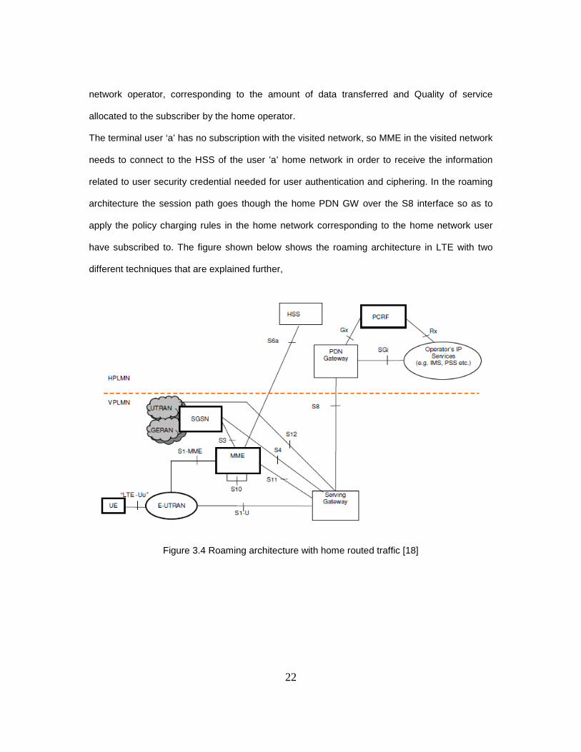
The terminal user ‘a’ has no subscription with the visited network, so MME in the visited network
needs to connect to the HSS of the user ’a’ home network in order to receive the information
related to user security credential needed for user authentication and ciphering. In the roaming
architecture the session path goes though the home PDN GW over the S8 interface so as to
apply the policy charging rules in the home network corresponding to the home network user
have subscribed to. The figure shown below shows the roaming architecture in LTE with two
different techniques that are explained further,
Figure 3.4 Roaming architecture with home routed traffic [18]

23
Figure 3.5 Roaming architecture with local breakthrough traffic [18]
Figure 3.6 Roaming in LTE/EPC [6]

24
The S8 interface shown in figure above model supports both signaling and data transfer
between the Serving GW and the home Packet Data Network GW. The S8 interface is based on
the Gp interface used in 2G and 3G packet core roaming architecture. In such a model the
access connectivity is provided by the visited network, while the connection to the external
networks is provided by the home network, external networks like IMS based services. The
anchor point in such model is home PDN GW, so it is known as ‘Home Routed Traffic’. However
this scheme or model proves to be inefficient in the case where the Home network and the
visited allows the possibility network is far away from each other, in the terms of cost and
network resources the inefficiency is observed. The Home Routed Traffic is also known as
traditional way of routing is also supported by Evolved Packet Core. 3GPP standard for the
same reason of inefficiency allows the possibility of routing the packets through the visited
network instead of routing through the home network. This type of service is also known as local
breakout it is also supported by Evolved Packet Core. Local traffic routing avoids the delay
caused by routing of the traffic to home network so its avoids the complete round trip and
preserves the network resources and this type of routing proves quite cost effective as
compared to Home routed traffic, especially in the case where the home network is far away
from the visited network. The visited PCRF retrieves the quality of service policy and charging
information from the home PCRF with the help of new interface S9.
3.2 EPS Mobility Management and connection Management states
The EMM is the abbreviation of the EPS Mobility Management States these states are
result of mobility management procedures such as tracking area update or attach procedures.
There are two different kinds of the EMM states, EMM- DEREGISTERED and EMM-
REGISTERED. While the states defined by the connection of the UE to EPC are known as ECM
(EPS Connection management states), there are two types of ECM states, namely ECM-IDLE
and ECM-CONNECTED. Basically EMM and ECM states are independent of each other, that is
transitions between the EMM states from registered to deregistered state can occur with any
25
concern of the ECM state, but on the other hand transition from the EMM-DEREGISTERD to
EMM-REGISTERED the UE is supposed to be in ECM-CONNECTED state. Further we will
describe each of the state as in definition and then explanation of the transitions.
3.2.1. Definitions of States
3.2.1.1 EMM-DEREGISTERED
In this deregistered state the MME holds no valid data for UE such as locating or
routing information, since the location of the UE is not known by the MME so it is not reachable
in this state. Still some of the UE context are stored in MME to avoid delay during the attach
procedure of the UE.
3.2.1.2 EMM-REGISTERED
In order for UE to enter EMM-REGISTERED state it has to do a successful registration
by doing the attach procedure either to E-UTRAN or GERAN/UTRAN. In this state the MME
holds the contents related to UE like MME is aware of the location of the UE to at least an
accuracy of the tracking areas list allocated to the UE. In this state the UE always have an
active PDN connection, and has setup the EPS security context. In the case when UE receives
the Attach reject message or TAU reject message the UE enters into the EMM-
DEREGISTERED state in the MME and in the UE. In case when all the bearers related to UE
are released the MME changes its EMM state to de registered for the UE. In the case when UE
try to connect to EUTRAN and detects that its bearers are released then the UE shall change its
state to EMM-DEREGISTERED.
3.2.1.3 ECM-IDLE
In ECM-IDLE mode in UE there does not exist any NAS signaling between the UE and
network, network does not hold any context related to UE also the interfaces S1-MME and S1-U
are not connected. In the case when UE is in EMM-REGISTERED and ECM-IDLE mode the UE
is supposed to update to update its location if it is in the tracking area other than its list, in order
to let network aware of availability of the UE, in the case when the RRC connection was

26
released with the cause of load balancing TAU required, UE is required to answer back the
paging messages from the MME in case to network initiated connection, and to request the
establishment of connection in order to perform the service request procedure in case to user
initiated connection. Both the UE and MME perform the transition from the IDLE state to
CONNECTED state when the signaling connection is established between the UE and the
network.
3.2.1.4 ECM-CONNECTED
In this state the UE is connected to the network, the MME is completely aware of the
UE related information with accuracy. In the case when the connection between the UE and
network is released or broken the UE shall enter in ECM-IDLE mode.
3.2.2. Transitions of States
The diagram below shows state transitions in EMM and ECM states. The first part of
diagram depicts the states in the MME, while the second diagram in this section depicts the
same for the UE. Diagrams are self explanatory.
Figure 3.7 EMM and ECM state transitions in the MME [18]

27
Figure 3.8 EMM and ECM state transitions in the UE [18]
3.3 Traffic management in MME
3.3.1 Load balancing between MMEs
When the UE attempts to connect to EUTRAN eNodeB connects the UE to MME via
S1-MME interface. The eNodeB is supposed to pick MME from the pool of MMEs, this
functionality of load balancing helps eNodeB to select appropriate MME from the pool of MME.
Every user terminal stores the address of its last attached MME and sends the same to the
access network at time of attach procedure (Attach procedures are explained in detail in later
part of the report) and network tries to attach terminal to same MME to which it was attached
last time of its connection. But in some of the scenarios like roaming or lost data or MME out of
service or MME overload, various other reasons eNodeB is not able to attach the UE to same
MME so it has to pick up new appropriate MME for the UE. For this function weight factor is
provided to every MME in pool, this weight factor helps eNodeB to determine which MME can
handle new attachments on itself, this weight factor determines the load on every MME in the
pool. So this weight factor is typically set according to the capacity of an MME node relative to
other MME nodes. The eNodeB is aware of this weight factor since MME sends it via S1-AP
messages.

28
3.3.2 Load re-balancing between MMEs
This functionality provides UE function that is connected on an MME to be moved to
any other MME. In the case when MME is doing load re-balancing that is dropping or releasing
some of the connections, MME has to make sure to do this by minimal impacts on the network
and users so it offloads the users with low activity instead of the high activity users. Offloading
process of any MME is a gradual procedure since if it offloads large number of users at same
time it can cause overload on other MME s in the pool area. In the case when the UE is in ECM-
CONNECTED mode MME initiates the S1 release procedure with a cause load balancing TAU
required. In the scenario when the MME is ready to offload the users due to over loading
problem it should not release all S1 connections immediately, instead it waits until S1 release is
performed due to inactivity, but in the case when MME has to be offloaded completely it can
enforce an S1 release for all UEs. UEs which are performing the tracking update procedure or
attach procedure initiated in the ECM-IDLE mode the MME completes this procedure and ends
with the MME releasing S1 with release cause load balancing TAU required. So the S1 and
RRC connections are released from MME side but the UE does the TAU update procedure and
connects the eNodeB without any registered MME information, so the eNodeB take the weight
factor into account and connects the UE to new MME in the pool area.
3.3.3 MME control of overload
In certain conditions the MME get overloaded with the high amount of the traffic trying
to connect the network via a particular MME. In such scenarios MME is capable with the
functionality to self control the overload by using the NAS signaling which connects the MME
with user terminal directly without any connection of the RAN, MME can reject these NAS
requests from the UE in the case of overload. In case hen the load is being generated by
eNodeB MME can start the overload procedure on S1 interface towards eNodeB in order to
control the situation. To control this MME selects any random eNodeB and starts sending
OVERLOADSTART message the particular eNodeB in order to let that particular eNodeB about
29
the overload situation. By sending this OVERLOADSTART message MME asks eNodeB to
reject all new RRC connection requests that are for non-emergency mobile originated services
or reject all new RRC connections requests for EPS Mobility Management signaling for that
MME or permit only those RRC connections which requests for emergency sessions and mobile
terminations requests for that MME. In the process of the OVERLOADSTART eNodeB rejects
the new non emergency RRC connections from UE and sends the appropriate reason to the UE
and starts the timer value for which limits RRC connection for a while, or can look for any other
MME in the pool which has not started OVERSTART message and is capable to establishing
new connection. During the overload situation MME tries to maintain support for emergency
bearer services. When MME is out of overload situation and it can handle new connections and
is ready to handle then, it sends OVERLOADSTOP message to eNodeB(s) which allows
eNodeB(s) to process new RRC connections for that MME.
3.4 Policy Charging and Control (PCC) architecture
Charging control by PCC is done by indentifying the service data flow and parameters
related to that service. These parameters are also known as charging identifiers these charging
identifiers are available to PCC architecture which are related to application level. There are
basically five different types of charging models available in PCC architecture namely, Volume,
Time, Volume and Time, Event based charging, and finally No charging. It is also possible to
apply different charging rates according to the user location that is home network or roaming
network. Charging also depends on the volume of the data flow or time of the day.
3.4.1 Reference Architecture
The Policy Charging and Control (PCC) functionality is comprised by the Policy and
Charging Enforcement function, the Bearer Binding and Event Reporting Function (BBERF), the
Policy and charging Rules Function, the Application Function, the Online Charging System, the
Offline Charging System, and the Subscription Profile Repository. The basic architecture

30
models are shown below which follows the detailed description of each reference points,
entities, and architectures.
Figure 3.9 Overall PCC logical Architecture (non roaming) [22]

31
Figure 3.10 Overall PCC Architecture (roaming with home routed access) [22]

32
Figure 3.11 Overall PCC architecture for roaming with OCEF in visited network (local breakout) [22]
3.4.2 Reference Points
3.4.2.1Rx reference point
The Rx reference point is the interface between the AF and the PCRF. Transportation
of application level session information from AF to PCRF is enabled by this reference point. This
information includes, but is not limited to: IP filter information which helps in identification of the
service data flow for control and/or charging mechanisms, and for QoS control the requirements
of the Bandwidth for certain application or media.

33
3.4.2.2 Gx reference point
The reference point that resides between the PCRF and the PCEF is Gx reference
point. This reference point enables dynamic control from PCRF over the PCC behavior at a
PCEF, and the signaling of PCC decision which governs the PCC behavior. This reference point
supports various functions such as the request for PCC decision from PCEF to PCRF, and
provision of the decision in vice versa direction, it also delivers the IP-CAN specific parameters
between PCRF and PCEF, negotiation of IP-CAN bearer establishment mode, and finally the
termination of the Gx session.
3.4.2.3 Sp reference point
The Sp reference point allows the PCRF to request the subscription information related
to the IP-CAN transport level policies from the SPR based on the subscriber ID, a PDN
identifier. Thus it resides between the PCRF and SPR. The SPR notifies any change in
subscriber profile via this reference point to PCRF if the PCRF requests any such notification.
3.4.2.4 Gy reference point
The reference point Gy resides between the OCS and PCEF, it allows online credit
control for service data flow based charging.
3.4.2.5 Gz reference point
This reference point connects the OFCS and the PCEF to enable transport of service
data flow based offline charging information.
3.4.2.6 S9 reference point
The reference point resides between the H-PCRF and the V-PCRF for the roaming with
home routed access and the local breakout access.
3.4.2.7 Gxx reference point
This reference point lies between the PCRF and the BBERF; it provides a PCRF to
have dynamic control over the BBERF behavior.

34
The PCRF entity in the EPS system controls policy control decisions and charging
control functions. The network controls the service data flow detection, gating, QoS and flow
based charging with the help of the PCRF towards the PCEF. PCRF accepts the service
information from the AF after applying the security procedures decided by operator. The PCRF
entity makes sure that the PCEF user plane traffic mapping and treatment is as it is in
subscription’s profile, and thus controls the treatment of the service data flow in the PCEF. The
PCRF controls the IP-CAN session with the specific restrictions, operator policy, SPR data,
permitted QCIs, and associated GBR and MBR limits.
The PCRF can reject a request received from the AF is the service information does not
match with the provided subscription profile or the operator defined policies. So the PCRF will
indicate that the particular service is not covered in the subscription information. The PCRF also
controls the authorization of the QoS resources from the information received from the AF
and/or from SPR to calculate the proper QoS class identifier, bitrates.
The PCRF can accept the input for OCC decision-making from the OCEF, the BBERF,
the SPR, and the AF (If AF and BBERF are present), the PCRF may use its own pre-defined
information.
The PCEF and/or BBERF provide the information to PCRF is needed like Subscriber
Identity, IP address (es) of the UE, IP-CAN bearer attributes, request type, type of IP-CAN,
location of the subscriber , a PDN ID, a PLMN identifier, and IP-CAN bearer establishment
mode.
The SPR connecting to a specific PDN can provide the information about a subscriber
like subscribers allowed services, for each allowed service a pre-emption priority, subscriber
allowed guaranteed bandwidth QoS, a list QCI together with the MBR limit and for real time
QoS class identifiers, GBR limit, charging related information, category of the subscriber, and
subscriber usage related monitoring information.

35
The application related information based on SIP and SDP is provided by the
Application Function (AF) if involved. This information includes subscriber identity, IP address of
the UE, Media type, media format, Bandwidth, source and destination IP address and port
numbers and the protocol, AF application identifier, AF communication service identifier, AF
record information, priority indicator, and emergency indicator.
The PCC architecture is responsible for providing the policy, charging control as well as
reporting an event for service data flows. The functional description includes binding
mechanism, reporting, credit management, event trigger, policy control, service prioritization
and conflict handling.

36
CHAPTER 4
AUTHETICATION AND MOBILITY MANAGEMENT
This chapter covers in detail Attach, Tracking area Update procedures, Service request
procedures, and Detach Procedure with different scenarios. All of the above mentioned
procedures user terminal goes through while maintaining mobility management.
4.1 Attach/ Track/ Detach procedure
4.1.1 E-UTRAN Initial Attach
Any user equipment or terminal if want to access the network services has to first
register itself on access network in order to utilize services provided by network. This
registration is known as Network Attachment. The network through this attach procedure
dedicates bearers in the network for that UE, PCC rules are applied during this bearer
establishment procedure. An UE can request for IP address allocation to the network during this
network attach procedure. User terminal provides Mobile Equipment Identity to the network, this
ME is used by MME and is verified with EIR in order to know the user terminal is in roaming or
is in the home network, the MME is supposed to pass this ME identity to the HSS, and if a PDN
GW outside of the VPLMN that is in Home routed traffic in roaming scenario
Initial attach procedure is done as emergency attach and is done for emergency
services but cannot gain normal services from the network. In the case when UE is trying to
attach network to access the normal services and do not have emergency bearers established
should initiate attach procedure indicating that attach is to receive emergency services. UEs
which are not camped on any cell and are not in limited service state, should initiate normal
initial attach that is the UE Requested PDN connectivity procedure to receive emergency EPS
bearer services.

37
Figure 4.1 E-UTRAN Initial Attach Procedure [18]
1. In the first step user equipment initiates the attach procedure by sending request to
eNodeB. This request is known as Attach request which comprises of information

38
related to UE as well as its last connection to the network if UE is not attaching to the
network as new user. The attach request includes IMSI or old GUTI, last visited TAI, UE
Core Network Capability, UE specific DRZ parameters, Attach Type, ESM message
container, KSIASME, NAS sequence number, NAS-MAC, additional GUTI, P-TMSI
signature message together with RRC parameters indicating the Selected Network and
the old GUMMEI. If UE provides P-TMSI and RAI then old GUTI may be derived from
them, IMSI is included in case when P-TMSI is not available. If UE hold a valid GUTI
and old GUTI indicates a GUTI mapped from a P-TMSI and RAI, then UE indicates
GUTI as additional GUTI. In the case when UE holds the old lists of TAIs it provides it to
the MME in order to produce good list of TAIs for new connection establishment for
same UE under same area. For security measurements UE includes security
parameters in order to protect integrity of Attach Request message by the NAS-MAC.
KSI, NAS sequence and NAS-MAC are included when UE has valid EPS security
parameters. In the case when UE does not have valid EPS parameters then Attach
Request message is not protected. If the UE has capabilities to connect
GERAN/UTRAN then it indicates it by sending NRSU in the Protocol Configuration
Option to indicate the support of the network requested bearer control in
UTRAN/GERAN. In case of Emergency Attach the UE sets the Attach type and
Request type to Emergency and includes IMSI in case it does not have valid GUTI or P-
TMSI. In case when UE does not have even valid IMSI then it includes IMEI.
2. The eNodeB is capable of deriving MME from the RRC parameters included which
carries old GUMMEI. In case when the MME indicates is not associated with eNodeB,
then it selects new MME by the MME selection functions as explained earlier. Then
after selecting this new MME eNodeB forwards the Attach Request to MME via S1-
MME together with selected network, CSG access mode, CSG ID, and TAI+ECGI of the
cell from where it receives the message to the new MME.

39
3. In scenario when UE claims to have GUTI and is clamped on new MME, then the new
MME utilizes GUTI to find old MME and sends the Identification Request to old MME to
request the IMSI. The old MME first verifies the request by NAS-MAC and then
responds with IMSI and MM context. IN case if the request is send to old SGSN it uses
P-TMSI to verify request and then responds with IMSI and MM context. If the UE is
unknown in old MME/SGSN or if in integrity check or in P-TMSI check it fails then old
MME/SGSN responds with error message with appropriate cause for it. This additional
GUTI helps new MME to find any already existing UE context stored in old MME. In
case of emergency attach request UE identifies itself with a temporary identity which is
not known to MME. MME in this case requests the UE itself for IMSI. UE if not aware of
IMSI then it can respond with IMEI.
4. When new MME figures it out that UE is unknown to old MME/SGSN then it sends
request message to UE asking for its IMSI. UE then responds with Identity Response
(IMSI).
5. A) If there not context related to UE is available in network, or if the integrity protection
failed then authentication and NAS security setup to activate integrity protection and
NAS ciphering are mandatory, or it is optional. The NAS security setup is performed in
this setup. If the Attach request is for Emergency support then the MME skips the
authentication and security setup or the MME accepts that the authentication may fail
and continues the attach procedure. After this step all the messages are NAS protected
unless it is for emergency attached.
B) In this step ME identity is requested from the UE, this can be done with the NAS
security set up to minimize signaling delays. Then MME sends this ME identity to EIR to
check ME identity and acknowledge same. According to the respond from the EIR MME
40
Decides if it continues with attach procedure with UE or reject it. In case of Emergency
attach the IMEI check may be performed with EIR and according to operator’s policies it
either continues with attach procedure or to reject the UE.
6. During the attach request if the UE has set the ciphered transfer flag, then MME
retrieves PCO or APN or both from UE. In case when UE has connection to multiple
PDNs then it is supposed to send the APN to the MME it is trying to establish
connection.
7. During this attach procedure if the UE is trying to connect same MME it was connect
before and there are some active bearers handled by the MME for this particular UE, it
sends Delete session request to all the gateways involved in the connection to delete all
the bearer context related to particular UE’s last connection. In the case when the
PCRF is deployed PDN GW initiated IP-CAN session termination procedure to let
PCRF know that all resources or bearers for this particular UE are released.
8. MME sends update location request message to HSS which includes MME identity,
IMSI, ME Identity, MME capabilities, and Update type in the case when MME is
changed to particular UE since last detach procedure or MME does not hold any valid
content for particular UE or if ME identity has changed or if UE provides IMSI or GUTI
which does not refer to valid context anywhere on the network. While if the attach type
is Emergency Attach then MME skips this message to HSS even the UE was not
successfully authenticated.
9. In this case when UE is attached to new MME since its last detach HSS sends the
Cancel Location to old MME, old MME responds with the Cancel Location acknowledge
to HSS and deletes all MM and bearer context related to particular UE. Same holds for
SGSN if UE was camped on SGSN in its last connection.
10. Since old MME/SGSN are supposed to delete all the MM and Bearer contexts it sends
Delete Session Request to all the gateways involved. As response all the gateways

41
acknowledge this request from old MME/SGSN by sending Delete Session Response.
PDN GW deploys IP-CAN Session Termination procedure if PCRF was involved.
11. In response to the Update location request sent by MME to HSS in step 8 HSS
acknowledges it by sending Update Location Ack message to MME. This ack contains
IMSI, and subscription data, this subscription data contains PDN subscription context
like ‘EPS subscribed QoS profile’ and subscribed APN-AMBR. In the case UE is not
allowed to attach in the tracking area provided or if the subscription procedure fails then
MME rejects the Attach request, but if all the checks are cleared then MME constructs a
context for the UE. In case of Emergency attach MME does not checks for access
restrictions, or subscription restrictions and ignores any unsuccessful update from HSS
and continues with the attach procedure.
12. In this step MME selects the Serving GW on serving gateway selection function and
allocates an EPS Bearer Identity for the Default Bearer associated with the UE, and
sends the Create Session Request which includes IMSI, MSISDN, MME TEID for
control plane, PDN GW address, PDN Address, APN, RAT type, Default EPS Bearer,
QoS, PDN type, APN-AMBR, EPS Bearer Identity, Protocol Configuration Options,
Handover Indication, ME Identity, User Location Information, User CSG information, MS
info Change reporting support indication, Selection Mode, Charging characteristics,
Trace reference, Trace type, trigger Id, OMC Identity, Maximum APN Restriction, the
protocol Type over S5/S8, Serving Network.
13. In this step Serving GW creates new entry in the EPS bearer table and sends the
create session request to the PDN GW. This address of PDN GW was provided by
MME to serving GW. Now serving GW receives some downlink packets from PDN GW
for the MME but it buffers this data and does not sends any downlink data notification
message to MME until it receives Modify Bearer Request message.
42
14. PDN GW contacts PCC and establishes IP-CAN Session and derives default PCC rules
for the UE. If PDN GW was provided with IMSI, APN, UE IP address, User location
Information, Serving Network, RAT type, APN-AMBR, and default EPS bearer QoS
then it provides these to PCRF. IMEI is used as identity instead of IMSI in case of
emergency attach by UE. This procedure is done when the Handover indication is not
present, but in the case where handover indication is present PDN GW executes a
PCEF Initiated IP-CAN Session Modification procedure with PCRF to report the new IP-
CAN type. Now if the dynamic PCC is not deployed then the PDN GW applies local
QoS policy.
15. After the establishment of IP-CAN Session Establishment PDN GW creates a new entry
in its EPS bearer context table and generates a Charging ID, and routes user plane
PDU from Serving GW to the packet data network, and start charging accordingly. In
order to respond to the request of Create Session Request from Serving GW PDN GW
sends Create Session Response to Serving GW. This response includes PDN GW
Address, PDN GW TEID, PDN Type, PDN Address, EPS Bearer Identity, EPS Bearer
QoS, Protocol Configuration Options, Charging ID, Prohibit Payload Compression, APN
restriction, MS Info change reporting.
16. The serving GW after receiving this Create Session Response from PDN GW sends a
create session response to new MME also. This message includes PDN Type, PDN
Address, Serving GW address, Serving GW TEID, EPS Bearer Identity, EPS Bearer
QoS, PDN GWs Address and TEID, Protocol Configuration Options, Prohibit payload
compression, APN Restriction, MS Info change Reporting Action, and APN-AMBR. In
case when Serving GW receives the MS info change reporting action start from PDN
GW it stores this bearer context and reports to PDN GW whenever a UE’s location
information change occurs that meets the PDN GW request.
43
17. MME sends an Attach Accept message to eNodeB which includes APN, GUTI, PDN
Address, TAI list, EPS Bearer Identity, Session Management request, Protocol
Configuration Options, NAS sequence number, NAS-MAC, IMS voice over PS session
supported Indication, Emergency Service Support Indicator. The GUTI is included in the
case when new MME allocates new GUTI and is sent via S1-MME control message
Initial context Setup Request. If the UE has UTRAN or GERAN capabilities and the
network also supports the mobility towards them then MME uses the EPS bearer QoS
information to derive the corresponding PDP context parameters. But if the case is vice
versa then MME shall not include the packet flow ID. For Emergency attach request no
AS security context is included in the S1 control messages and if the UE is not
authenticated then there is no NAS level security too. In these services UE is allowed
only to request PDN connectivity for emergency services.
18. RRC Connection Reconfiguration message including the EPS radio bearer identity is
sent to UE by eNodeB with the Attach accept message. The UE can store the QoS
Negotiated, Radio Priority, Packet Flow ID and TI, which it receives in session
management request.
19. UE responds to eNodeB with the RRC connection Reconfiguration Complete message.
20. The new MME receives the initial context response message from the eNodeB, this
message includes temporary ID of eNodeB and address of eNodeB used for downlink
traffic on the S1_U reference point.
21. Attach complete message along with Direct Transfer message is sent by UE to
eNodeB, this attach complete message includes EPS Bearer Identity, NAS sequence
number, and NAS-MAC.
22. This attach accept is forwarded to the MME by eNodeB. After the attach procedure is
done UE has got the PDN Address, so UE is now capable to send data on Uplink which
will go through Serving GW and PDN GW. In case when UE requested for dual address

44
that is IPv4v6 but has received only single address PDN type like either IPv4 or IPv6,
then UE can request for one more time for one more address which is going to be other
than type that it is already granted.
23. New MME after receiving Attach accept and Initial context response message sends a
modify bearer request which includes EPS Bearer Identity, eNodeB address, eNodeB
TEID, handover indication.
24. Serving GW after receiving Modify bearer response from PDN GW sends it to MME,
after doing this it can send its buffered downlink packets which were buffered in step
13.
25. MME sends a Notify request message to HSS after receiving Modify Bearer Response,
which if indicates no handover and an EPS bearer was established and the subscription
data indicates that the user is allowed to perform handover to non-3GPP accesses, and
if MME selected a PDN GW that is different from the PDN GW identity which was
indicated by HSS in the PDN subscription context. For an Emergency Attach it does not
sends any type of Notify request.
26. The HSS responds to MME after storing the APN and PDN GW identity pair.
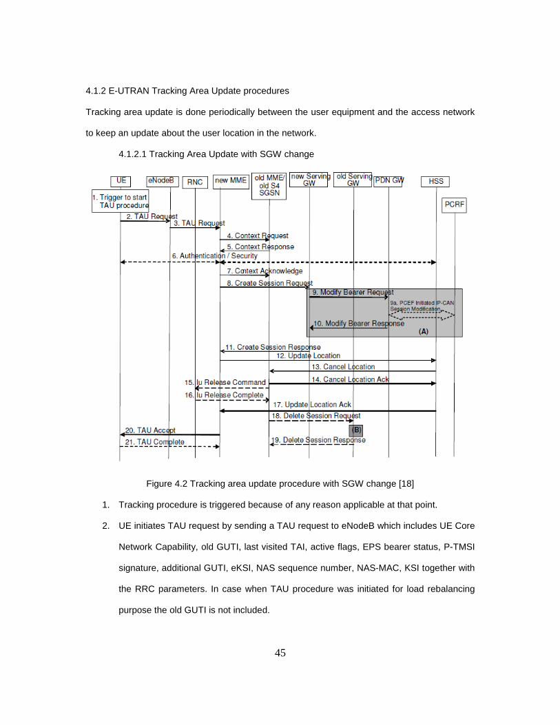
45
4.1.2 E-UTRAN Tracking Area Update procedures
Tracking area update is done periodically between the user equipment and the access network
to keep an update about the user location in the network.
4.1.2.1 Tracking Area Update with SGW change
Figure 4.2 Tracking area update procedure with SGW change [18]
1. Tracking procedure is triggered because of any reason applicable at that point.
2. UE initiates TAU request by sending a TAU request to eNodeB which includes UE Core
Network Capability, old GUTI, last visited TAI, active flags, EPS bearer status, P-TMSI
signature, additional GUTI, eKSI, NAS sequence number, NAS-MAC, KSI together with
the RRC parameters. In case when TAU procedure was initiated for load rebalancing
purpose the old GUTI is not included.

46
3. Now eNodeB derives the MME from the RRC parameters which includes old GUMMEI
and indicated Selected Network. If in case eNodeB is not able to find the MME derived
from the RRC parameters then it selects MME by the MME selection function. The
eNodeB is unable to find the MME stated in the RRC parameters if the MME is not
associated with the eNodeB or the GUMMEI is not available or the UE indicates that
TAU procedure was initiated because of the load re-balancing procedure. After finding
the MME eNodeB forwards the TAU Request message to MME.
4. The new MME uses the GUTI provided by UE to find old MME/SGSN and sends a
context request message to old MME/SGSN in order to retrieve the user related
information. Old MME uses the TAU context request message to validate new MME to
have user related information, while SGSN uses the P-TMSI Signature and if any error
found it responds it with a cause as error. Now the new MME runs the security function,
and if this function validates the UE completely then it sends the context request
message with the UE validated set. Now out of two possibilities if the new MME
indicates it has authenticated the UE or if the old MME/SGSN correctly validates the
UE, the old MME/SGSN runs a timer. In case of emergency type of connection request
the old MME/SGSN continues to send user related Context response even if it does not
authenticate the UE, this is done in the network that supports unauthenticated UEs.
5. The old MME responds to the context request from new MME with a Context Response
which includes IMSI, ME Identity, MSISDN, MM Context, EPS Bearer Context, Serving
GW signaling Address and TEIDs, ISR Supported, MS info change Reporting Action if
available, UE core Network Capability, UE specific DRX parameters. While SGSN
responds it with message that includes MM Context, EPS Bearer Contexts, Serving
Gateway Signaling address and TEIDs, ISR supported, MS info change if available, UE
core network capability, and UE specific DRX parameters. IN the case when the UE is
47
not known to old MME/SGSN it responds with the error message with the specific
cause.
6. In the case when UE fails the integrity check in step 2 then it is mandatory to run the
authentication function, while if the UE is only using the emergency services then the
authentication can be skipped by the MME.
7. The new MME determines if the Serving GW is relocated this could be if old Serving
GW cannot serve the UE, or if the new serving GW is expected to serve the UE for
longer time or with more optimal UE to PDN GW path, or if the new serving GW can be
co-located with PDN GW. This new MME then sends the Context Acknowledge
message to old MME/SGSN indicating that the Serving GW is changed. This leads the
old MME/SGSN to mark that GWs in UE contexts in HSS are invalid. So old
MME/SGSN decides to update these contexts whenever the UE initiates TAU request
back to them before completing the ongoing request. In the case when UE is not
authenticated even by new MME then it rejects the TAU request from UE and sends a
reject indication to old MME/SGSN which allows old MME/SGSN to continue as if the
Identification and context request was never made.
8. The new MME sends the create session request to new Serving GW which includes
IMSI, bearer contexts, MME address and TEID, Type, the Protocol type over S5/S8,
RAT type, Serving Network. Type indicates SGW to send the create Session request to
PDN GW.
9. If there is any change like RAT type then Serving GW informs that to PDN GW or any
change which is concerned to PDN GW.
A. In the case that there is change in RAT type then PDN GW sends this information
to PCRF by sending Modify Bearer Request per PDN Connection, this request
includes Serving GW Address and TEID, RAT type, and Serving Network.

48
10. PDN GW to update its own Bearer Contexts and sends the Modify Bearer Response to
Serving GW.
11. The Serving gateway respond to the Create Session Request with a response which
includes Serving GW address and TEIDs and PDN GW TEIDs, GRE keys for uplink
traffic to the new MME. Serving GW also updates its Bearer contexts this allows
Serving GW to route the bearer PDUs to the PDN GW.
12. The new MME verifies if it holds the subscription for UE identified by GUTI, additional
GUTI, or by IMSI received from the context response from the old MME/SGSN. If the
new MME does not find any subscription data for the particular UE then it sends the
Update Location Request to the HSS. In the case of Emergency MME can skip this
update location process and can continue with TAU procedure.
13. The HSS sends the Cancel Location message to old MME which has Cancellation type
set to update procedure.
14. The timer which was started in step 4 by the old MME if this timer is no more running
then the old MME deletes bearer context related to UE, or if the timer expires then it
performs same action. The timer ensures that the old MME holds MM context related to
the UE in the case when UE initiates new Tau procedure before completing the ongoing
TAU procedure with new MME. Old MME acknowledges this with Cancel Location Ack.
15. In the case of old SGSN if it receives the Context Acknowledge message it sends
command to RNC to release Iu connection if the timer started in step 4 has expired.
16. The RNC acknowledge this release command from old SGSN with Iu Release
Complete message.
17. In this step HSS responds to new MME for Update Location Request with an Update
Location Acknowledge message, in case if the Update location request was rejected by
HSS then MME would have rejected the TAU request from UE with an appropriate
cause.

49
18. Old MME/SGSN waits for timer started in step 4 after it expires it releases any local
MME or SGSN bearer resources and sends a Delete Session Request to old Serving
Gateway since there is change in Serving Gateway. This prompts old Serving Gateway
to initiate delete procedure towards the PDN GW.
19. The serving GW responds to the request made in step 18 by sending a Delete Session
Response message and discards any packets for the UE.
20. MME sends a TAU accept message to UE, this message includes GUTI, TAI List, EPS
bearer status, NAS sequence number, NAS-MAC, IMS Voice over PS session
supported, Emergency Service Support indicator, LCS Support Indication. MME provide
the eNodeB with Handover Restriction Lists. In case if due to regional subscription
restrictions UE is not allowed to access the TA then MME sends the TAU Update
Reject to the UE with appropriate cause.
21. UE responds to new MME with acknowledgement by sending TAU complete message
to the MME if the GUTI was included in TAU accept message.

50
4.1.2.2 Tracking Area Update without SGW change
Figure 4.3 Tracking Area Update without Serving GW change [18]
1. Tracking procedure is triggered because of any reason applicable at that point.
2. UE initiates TAU request by sending a TAU request to eNodeB which includes UE Core
Network Capability, old GUTI, last visited TAI, active flags, EPS bearer status, P-TMSI

51
signature, additional GUTI, eKSI, NAS sequence number, NAS-MAC, KSI together with
the RRC parameters. In case when TAU procedure was initiated for load rebalancing
purpose the old GUTI is not included.
3. Now eNodeB derives the MME from the RRC parameters which includes old GUMMEI
and indicated Selected Network. If in case eNodeB is not able to find the MME derived
from the RRC parameters then it selects MME by the MME selection function. The
eNodeB is unable to find the MME stated in the RRC parameters if the MME is not
associated with the eNodeB or the GUMMEI is not available or the UE indicates that
TAU procedure was initiated because of the load re-balancing procedure. After finding
the MME eNodeB forwards the TAU Request message to MME.
4. The new MME uses the GUTI provided by UE to find old MME/SGSN and sends a
context request message to old MME/SGSN in order to retrieve the user related
information. Old MME uses the TAU context request message to validate new MME to
have user related information, while SGSN uses the P-TMSI Signature and if any error
found it responds it with a cause as error. Now the new MME runs the security function,
and if this function validates the UE completely then it sends the context request
message with the UE validated set. Now out of two possibilities if the new MME
indicates it has authenticated the UE or if the old MME/SGSN correctly validates the
UE, the old MME/SGSN runs a timer. In case of emergency type of connection request
the old MME/SGSN continues to send user related Context response even if it does not
authenticate the UE, this is done in the network that supports unauthenticated UEs.
5. The old MME responds to the context request from new MME with a Context Response
which includes IMSI, ME Identity, MSISDN, MM Context, EPS Bearer Context, Serving
GW signaling Address and TEIDs, ISR Supported, MS info change Reporting Action if
available, UE core Network Capability, UE specific DRX parameters. While SGSN
responds it with message that includes MM Context, EPS Bearer Contexts, Serving

52
Gateway Signaling address and TEIDs, ISR supported, MS info change if available, UE
core network capability, and UE specific DRX parameters. IN the case when the UE is
not known to old MME/SGSN it responds with the error message with the specific
cause.
6. In the case when UE fails the integrity check in step 2 then it is mandatory to run the
authentication function, while if the UE is only using the emergency services then the
authentication can be skipped by the MME.
7. The new MME determines if the Serving GW is relocated this could be if old Serving
GW cannot serve the UE, or if the new serving GW is expected to serve the UE for
longer time or with more optimal UE to PDN GW path, or if the new serving GW can be
co-located with PDN GW. This new MME then sends the Context Acknowledge
message to old MME/SGSN indicating that the Serving GW is changed. This leads the
old MME/SGSN to mark that GWs in UE contexts in HSS are invalid. So old
MME/SGSN decides to update these contexts whenever the UE initiates TAU request
back to them before completing the ongoing request. In the case when UE is not
authenticated even by new MME then it rejects the TAU request from UE and sends a
reject indication to old MME/SGSN which allows old MME/SGSN to continue as if the
Identification and context request was never made.
8. VOID
9. The new MME derives the Contexts related to UE from old MME/SGSN and establishes
the EPS bearers in the indicated order and sends a Modify Bearer to Serving GW which
includes new MME address and TEID, Serving Network identity, ISR activated, RAT
type message as per PDN connection.
10. If there is any change like RAT type then Serving GW informs that to PDN GW or any
change which is concerned to PDN GW.

53
11. In the case that there is change in RAT type then PDN GW sends this information to
PCRF by sending Modify Bearer Request per PDN Connection, this request includes
Serving GW Address and TEID, RAT type, and Serving Network.
12. PDN GW sends a Modify Bearer Response to Serving GW and updates its own context
field in order to route the DL PDUs to correct Serving GW.
13. In this step Serving GW responds to new MME with a Modify Bearer Response and
updates its own bearer context. Serving GW updates its context related to MME control
plane stored locally and keeps the SGSN related information unchanged. The Modify
Bearer Response from Serving GW to new MME includes Serving GW address and
TEID for uplink Traffic, this allows serving GW to route Bearer PDUs to the PDN GW
when received from eNodeB.
14. The new MME verifies if it holds the subscription for UE identified by GUTI, additional
GUTI, or by IMSI received from the context response from the old MME/SGSN. If the
new MME does not find any subscription data for the particular UE then it sends the
Update Location Request to the HSS. In the case of Emergency MME can skip this
update location process and can continue with TAU procedure.
15. The HSS sends the Cancel Location message to old MME which has Cancellation type
set to update procedure.
16. The timer which was started in step 4 by the old MME if this timer is no more running
then the old MME deletes bearer context related to UE, or if the timer expires then it
performs same action. The timer ensures that the old MME holds MM context related to
the UE in the case when UE initiates new Tau procedure before completing the ongoing
TAU procedure with new MME. Old MME acknowledges this with Cancel Location Ack.
17. In the case of old SGSN if it receives the Context Acknowledge message it sends
command to RNC to release Iu connection if the timer started in step 4 has expired.

54
18. The RNC acknowledge this release command from old SGSN with Iu Release
Complete message.
19. In this step HSS responds to new MME for Update Location Request with an Update
Location Acknowledge message, in case if the Update location request was rejected by
HSS then MME would have rejected the TAU request from UE with an appropriate
cause.
20. MME sends a TAU accept message to UE, this message includes GUTI, TAI List, EPS
bearer status, NAS sequence number, NAS-MAC, IMS Voice over PS session
supported, Emergency Service Support indicator, LCS Support Indication. MME provide
the eNodeB with Handover Restriction Lists. In case if due to regional subscription
restrictions UE is not allowed to access the TA then MME sends the TAU Update
Reject to the UE with appropriate cause.
21. UE responds to new MME with acknowledgement by sending TAU complete message
to the MME if the GUTI was included in TAU accept message.

55
4.1.3 Service Request procedures
There are basically two types of service triggers depending on the initiation of the trigger namely
UE triggered Service Request and Network triggered Service Request.
4.1.3.1 UE triggered Service Request
Figure 4.4 UE triggered Service [18]
1. UE triggers service request by sending NAS request towards MME with RRC message
to eNodeB.
2. Since Radio network acts as transparent to NAS messages it forwards to particular
MME, this NAS request consists of NAS message, TAI+ECGI of the serving cell, S-
TMSI, CSG ID, CSG access Mode. In case of emergency EPS bearers MME shall
deactivate all non emergency bearers and accept the Service Request.
3. In this step Authentication/Security procedures are performed.
4. MME sends the Initial Context setup request to eNodeB, this request includes Serving
GW address, S1-TEIDs, EPS Bearer QoS, Security Context, MME Signaling
56
Connection ID, Handover Restriction List, and CSG Member ship indication. S1 bearers
and radio bearers are activated in this step. In case of emergency of connection MME
requests only to establish bearers for emergency EPS bearers.
5. Radio bearer establishment is done by eNodeB and the user plane security is
established, in case when the EPS bearers are already established the synchronization
process is performed between the UE and network.
6. UE sends the uplink data to eNodeB which routes to the particular serving gateway
address which was provided to it in step 4. This serving GW then forward the data to
the associated PDN GW.
7. In response to Initial Context request from MME eNodeB responds with Initial Context
Setup Complete response which includes eNodeB address, List of accepted EPS
bearers, List of rejected EPS bearers, S1 TEID for Downlink to the MME.
8. Serving GW is now capable to send the downlink packet data since it had received
Modify Bearer Request Message per PDN Connection from the MME, this message
includes eNodeB address, S1 TEID for downlink, Delay Downlink Packet Notification
Request information.
9. Serving GW sends the bearer modification request to PDN GW in case if there is any
change serving GW in RAT type or in UE location as compared to last time.
10. PDN GW gets the PCC rules from PCRF by IP-CAN session modification process if the
dynamic PCC is deployed. In case when dynamic PCC is not deployed then it may
apply local QoS policy.
11. PDN GW responds to the serving GW with Modify Bearer Response.
12. Serving GW responds to the MME with Modify Bearer Response.
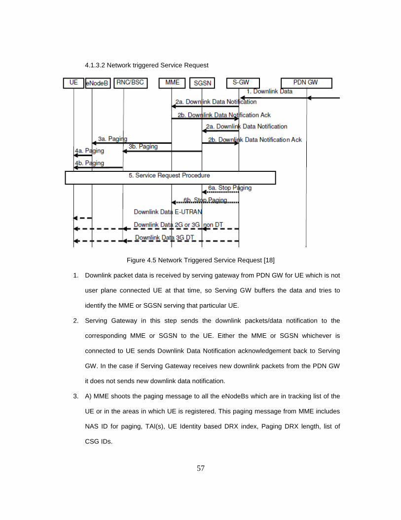
57
4.1.3.2 Network triggered Service Request
Figure 4.5 Network Triggered Service Request [18]
1. Downlink packet data is received by serving gateway from PDN GW for UE which is not
user plane connected UE at that time, so Serving GW buffers the data and tries to
identify the MME or SGSN serving that particular UE.
2. Serving Gateway in this step sends the downlink packets/data notification to the
corresponding MME or SGSN to the UE. Either the MME or SGSN whichever is
connected to UE sends Downlink Data Notification acknowledgement back to Serving
GW. In the case if Serving Gateway receives new downlink packets from the PDN GW
it does not sends new downlink data notification.
3. A) MME shoots the paging message to all the eNodeBs which are in tracking list of the
UE or in the areas in which UE is registered. This paging message from MME includes
NAS ID for paging, TAI(s), UE Identity based DRX index, Paging DRX length, list of
CSG IDs.

58
B) In the case when UE is registered under SGSN it sends the paging message to the
RNC/BSS
4. A. eNodeB after receiving paging message from the MME pages for the particular UE.
B. RNC/BSS in case when UE is registered at SGSN sends the paging message for
UE.
5. UE upon reception of the paging message initiates UE triggered Service request in case
when it is in ECM-IDLE mode, since MME already posses a signaling connection for the
UE it starts establishing bearers for the UE. Both MME and SGSN starts timer as soon
as they sends a paging message for the particular UE, as the timer expires they again
retransmits the paging message the repetition of the paging message depends on the
operator’s policies. In case when MME/SGSN does not receive any response from UE
for the paging message they it notifies SGW about the paging failure. The Serving GW
then deletes the any buffered packets for the UE or rejects the service triggered
procedure.
6. A. After receiving response from the MME or in other words when serving GW realizes
that the UE is clamped on E-UTRAN it sends a paging stop message to SGSN.
B. Same as in case when Serving GW is responded from the UTRAN/GERAN it sends
stop paging message to MME.
4.1.4 Detach Procedure
Whenever UE no longer wants any service from network it triggers a detach procedure, in
the case when Network decides that the UE no longer can have access to E-UTRAN it
initiates detach procedure. The detach procedure in which network or UE requests detach
from each other known as Explicit Detach, while in the case neither UE or network does
detach without notifying each other known as Implicit Detach. Commonly there are four
different types of detach scenarios namely UE Initiated Detach Procedure, MME-Initiated

59
Detach procedure, SGSN Initiated procedure with ISR activated, and HSS- Initiated Detach
procedure. These detach procedures are explained in detail below.
4.1.4.1 UE initiated Detach Procedure
4.1.4.1.1 Case when UE is connected to E-UTRAN
Figure 4.6 UE Initiated detach Procedure with E-UTRAN [18]
1. UE sends a Detach request to MME which includes GUTI and switch off. The eNodeB
forwards this message to MME including TAI+ECGI parameters. If the request sent to
MME is from CGS cell with Switch off parameter indicating that the detach procedure is
initiated because of a switch off situation where CSG subscription or CSG ID is not
present or had expired then MME initiates the Detach procedure.
2. As MME receives the Detach Request it sends a Delete Session request to Serving GW
as per PDN connection and requests SGW to deactivate the active bearers for this
particular UE.
3. As the Serving GW receives the Delete Session Request from the MME/SGSN it
checks for the ISR mode of the UE. If the ISR mode is activated then it first deactivates

60
the ISR mode of the UE and then releases the EPS bearers related to that particular UE
and responds with the Delete Session Response. In the case where ISR mode was not
activated Serving GW directly deletes the EPS bearers and jumps to step 6 and sends
a Delete Session request to PDN GW per PDN connection.
4. In the case when ISR mode is activated MME sends a Delete Indication to SGSN
associated to it.
5. SGSN deletes the PDP contexts related to particular UE in the Serving GW by sending
a Delete Session Request per PDN connection.
6. This step is initiated in step 2 in case where ISR mode was not deactivated where SGW
sends the delete Session Request to PDN GW per PDN connection.
7. In this step it is PDN GW that acknowledges SGW with a Delete Session Response
with a cause.
8. PDN GW contacts PCRF to initiate the PCEF initiated IP-CAN Session Termination
Procedure to indicate PCRF that the bearers related to particular UE are released.
9. Serving performs function of acknowledgement by sending a Delete Session Response
to the SGSN.
10. SGSN acknowledges the MME by sending a Detach Acknowledge Message.
11. In the case when detach was not done because of switch off condition MME sends a
Detach Accept message to UE.
12. In order to finish the detach procedure MME initiates releasing S1-MME signaling
connection by sending S1 Release Procedure.
13. MME notifies HSS to remove APN and PDN GW identity pairs for this UE as soon as it
receives Delete Session Response from Serving Gateway.
14. HSS sends the response to MME after deleting APN and PDN GW pairs for this
particular UE.

61
4.1.4.1.2 Case when UE is connected to GERAN/UTRAN with ISR Activated
Figure 4.7 UE Initiated Detach Procedure when UE is connected to GERAN/UTRAN with ISR activated. [18]
1. UE sends a Detach request to SGSN which includes Detach type, P-TMSI and switch
off. If the request sent to SGSN is from CGS cell with Switch off parameter indicating
that the detach procedure is initiated because of a switch off situation where CSG
subscription or CSG ID is not present or had expired then SGSN initiates the Detach
procedure.
2. As SGSN receives the Detach Request it sends a Delete Session request to Serving
GW as per PDN connection and requests SGW to deactivate the active bearers for this
particular UE.
3. As the Serving GW receives the Delete Session Request from the SGSN it checks for
the ISR mode of the UE. Since the ISR mode is activated it deactivates the ISR mode
of the UE and then releases the EPS bearers related to that particular UE and responds
with the Delete Session Response.
62
4. Since in this case when ISR mode is activated SGSN sends a Delete Indication to MME
associated to it.
5. MME deletes the PDP contexts related to particular UE in the Serving GW by sending a
Delete Session Request per PDN connection.
6. This step is initiated in step 2 in case where ISR mode was not deactivated where SGW
sends the delete Session Request to PDN GW per PDN connection.
7. In this step it is PDN GW that acknowledges SGW with a Delete Session Response
with a cause.
8. PDN GW contacts PCRF to initiate the PCEF initiated IP-CAN Session Termination
Procedure to indicate PCRF that the bearers related to particular UE are released.
9. Serving performs function of acknowledgement by sending a Delete Session Response
to the MME.
10. MME acknowledges the SGSN by sending a Detach Acknowledge Message.
11. In the case when detach was not done because of switch off condition SGSN sends a
Detach Accept message to UE.
12. In order to finish the detach procedure SGSN initiates releasing PS signaling
connection if the MS was GPRS detached.
13. SGSN notifies HSS to remove APN and PDN GW identity pairs for this UE as soon as it
receives Delete Session Response from Serving Gateway.
14. HSS sends the response to SGSN after deleting APN and PDN GW pairs for this
particular UE.

63
4.1.4.2 MME initiated Detach Procedure
Figure 4.8 MME Initiated Detach Procedure [18]
1. MME initiated Detach procedure and either be Implicit or explicit, in the case when UE
has no communication with the access network for long period of time MME can
implicitly detach UE and does not sends any kind of detach request to UE. On the other
hand if UE is in ECM-CONNECTED mode and MME wants to detach UE then it starts
detach procedure and explicitly detach UE from the network and sends detach request
to UE. In case of emergency attached UE MME detaches UE implicitly because of long
inactivity period.
2. If there are any active EPS bearer related to particular UE in SGW then MME sends a
Delete Session Request to Serving Gateway and requests SGW to delete all the EPS
context bearers related to UE per PDN connection.
3. If SGW receives Delete Session Request when ISR mode is activated it first
deactivates ISR mode and then deletes EPS bearers and responds with Delete Session

64
Response to MME. In case when ISR mode is not activated it directly deletes EPS
bearer contexts and jumps to step 6 by sending a Delete Session Request to PDN GW.
4. When ISR mode active is found then MME sends Detach Notification to associated
SGSN and let SGSN know if it a local or complete detach request.
5. If cause sent by MME indicates complete detach request then it sends a Delete Session
Request to SGW or if it is local detach then it deactivates ISR and jumps to step 10.
6. Since ISR is not activated SGW sends a Delete Bearer Request to PDN GW per PDN
connection.
7. PDN GW responds to SGW by sending a Delete Session Response message.
8. If PCRF is configured then PDN GW makes sure that it sends IP-CAN Session
Termination Request to PCRF and notifies it of releasing EPS Bearers related to
particular UE.
9. In this step SGW responds to SGSN by sending Delete Session Response message.
10. SGSN in this step responds to MME by sending a Detach Acknowledge message.
11. UE sends a Detach accept message to MME as NAS signaling message, eNodeB
transfers this NAS signal to MME by adding TAI+ECGI to MME.
12. MME now releases S1-MME signaling message by sending a S1-Release Message to
eNodeB, in the case when detach request asks UE to make a new attach then UE
performs a reattach procedure as soon as the RRC connections are completely
removed.
13. As MME receives a Delete Session response from SGW and it recognizes that UE is
allowed to perform non-3GPP handover then it sends a Notify Request to HSS and
requests HSS to remove the APN and PDN GW identity pairs.
14. HSS responds to MME after removing APN and PDN GW identity pairs with a Notify
Response.
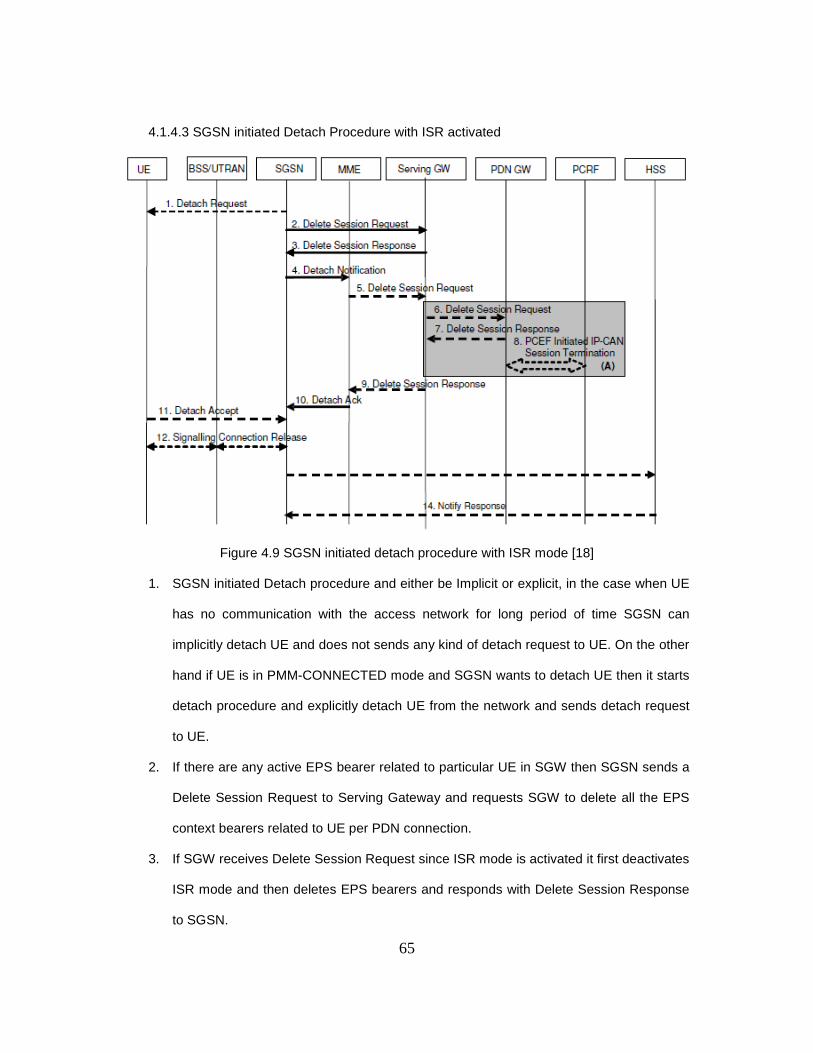
65
4.1.4.3 SGSN initiated Detach Procedure with ISR activated
Figure 4.9 SGSN initiated detach procedure with ISR mode [18]
1. SGSN initiated Detach procedure and either be Implicit or explicit, in the case when UE
has no communication with the access network for long period of time SGSN can
implicitly detach UE and does not sends any kind of detach request to UE. On the other
hand if UE is in PMM-CONNECTED mode and SGSN wants to detach UE then it starts
detach procedure and explicitly detach UE from the network and sends detach request
to UE.
2. If there are any active EPS bearer related to particular UE in SGW then SGSN sends a
Delete Session Request to Serving Gateway and requests SGW to delete all the EPS
context bearers related to UE per PDN connection.
3. If SGW receives Delete Session Request since ISR mode is activated it first deactivates
ISR mode and then deletes EPS bearers and responds with Delete Session Response
to SGSN.

66
4. When ISR mode active is found then SGSN sends Detach Notification to associated
MME and let MME know if it a local or complete detach request.
5. If cause sent by SGSN indicates complete detach request then it sends a Delete
Session Request to SGW or if it is local detach then it deactivates ISR and jumps to
step 10.
6. Since ISR is not activated now SGW sends a Delete Bearer Request to PDN GW per
PDN connection.
7. PDN GW responds to SGW by sending a Delete Session Response message.
8. If PCRF is configured then PDN GW makes sure that it sends IP-CAN Session
Termination Request to PCRF and notifies it of releasing EPS Bearers related to
particular UE.
9. In this step SGW responds to MME by sending Delete Session Response message.
10. MME in this step responds to SGSN by sending a Detach Acknowledge message.
11. UE sends a Detach accept message to SGSN.
12. SGSN now releases PS signaling message in the case when detach request does not
requests UE to make a new attach.
13. As MME receives a Delete Session response from SGW and it recognizes that UE is
allowed to perform non-3GPP handover then it sends a Notify Request to HSS and
requests HSS to remove the APN and PDN GW identity pairs.
14. HSS responds to MME after removing APN and PDN GW identity pairs with a Notify
Response.

67
4.1.4.4 HSS initiated Detach Procedure
Figure 4.10 HSS-initiated Detach Procedure [18]
1. In this procedure the HSS initiates the Detach Procedure for any particular UE whose
MM contexts and EPS Bearers are to be removed. SO HSS sends a Cancel Location
message with cancellation type to MME or SGSN whichever is registered or both in
case ISR is activated.
2. MME/SGSN sends a Detach Request to UE which is in ECM-CONNECTED mode and
informs UE that it has been detached from the network. In case when UE is in ECM-
IDLE mode then MME pages the UE.
3. A. If there are any active EPS bearer related to particular UE in SGW then MME sends
a Delete Session Request to Serving Gateway and requests SGW to delete all the EPS
context bearers related to UE per PDN connection.

68
B. If there are any active EPS bearer related to particular UE in SGW then SGSN sends
a Delete Session Request to Serving Gateway and requests SGW to delete all the EPS
context bearers related to UE per PDN connection.
4. When the Serving Gateway receives Delete Session Request from MME/SGSN when
ISR mode is activated it deactivates the ISR mode and responds with Delete Session
Response. In the case when ISR mode is deactivated it releases EPS bearer contexts
and forwards a delete session request to PDN GW.
5. The PDN GW acknowledges serving gateway request by sending a Delete Session
Response with a cause.
6. PDN GW initiated IP-CAN Session termination procedure towards PCEF in order to let
PCRF know that the EPS bearer contexts related to particular UE are released.
7. Serving GW sends a Delete Session Response to MME/SGSN according to the
connectivity.
8. UE responds to Detach Request sent by MME/SGSN by sending a Detach Accept
Message to either MME or SGSN depending on the access network UE is camping on.
9. MME/SGSN sends a confirmation to HSS by sending a Cancel Location Ack message.
10. As MME receives detach accept message from UE it releases S1-MME connection by
initiating S1 Release Procedure. In the case of SGSN it releases PS signaling
connection to complete the detach procedure initiated by HSS.
4.2 TCP Performance Analysis
Many industrial researchers are performing tests on LTE; one such test is performed by
Andras Racz from Ericsson, with Andras Temesvary, and Norbert Reider from Budapest
University of Technology and Economics. In this paper namely “Handover Performance in
3GPP Long Term Evolution (LTE) Systems”, authors had talked about the problem related to
the handover process in LTE when eNodeB change occurs. In this particular paper authors
provide an overview of the LTE intra-access handover procedure and evaluate its performance
69
focusing on the user perceived performance aspects of it. Whenever any handover procedure is
performed and if the eNodeB is moved to new eNodeB then protocol endpoints in source
eNodeB are required to transmit to new target eNodeB. As we have seen in earlier part of report
source initiates the handover procedure in this case source eNodeB performs this action and
sends the handover command message to UE. After sending the handover command source
eNodeB suspends the RLC/MAC protocols and it starts transmitting the SDUs towards target
eNodeB that have not been successfully send to UE. After executing the handover procedure
UE sends a handover complete message to target eNodeB. In this execution procedure UE
performs a random access procedure in which it gets the uplink time alignment and performs
time synchronization between the UE and the target eNodeB. As target eNodeB receives
handover complete message from UE it starts sending downlink data and it sends a path
switching message to gateway it is connected in core network and finally makes sure the
resources in source eNodeB are released. Here is the point where problem rises, there can be
a time interval after the path switch when packets both on the direct path (GW to target
eNodeB) and also on the forwarding path (GW to source eNodeB to target eNodeB). This raises
problem of receiving packets out of order. Since the packets on direct path will reach earlier
then the forwarding path. These out of order packets degrade the performance of TCP
performance and may result in loss of system utilization. Authors in order to explain this
problem and to analyze this situation take in account two different cases. In case1 the downlink
packets suffering out of order arrival were generated at the correspondent node in response to
the last TCP ACK that was sent via source eNodeB prior to the handover. While in case 2 these
out of order packets were generated after the handover in other words in response to a TCP
ACK sent via the target eNodeB. In mathematics Case 1 is explained as,
Where, is delay between eNodeB and Gateway, is Internet delay, and is radio
interruption delay during handover. This inequality shows that when path switching command

70
reaches to GW there are packets in the tunnel above gateway, so during the path switching last
packet was sent on forwarding path while the very next packet is sent on the direct path. So
since we know delay on forwarding path is greater that direct path packets reach out of order at
target eNodeB. This delay can be represented by mathematical equation as,
Case 2 can be represented as the following equation,
In the above equation left hand side of inequality is delay till the last packet that was
generated in response to last TCP ACK sent via forwarding path to target eNodeB, while right
hand side represents the delay till the first packet generated in response to TCP ACK sent via
direct path to the target eNodeB. This leads to problem of packets arriving out of order at target
eNodeB. If we combine both the cases out of order packets can occur only if the following
conditions hold,
In order to solve this problem authors proposes a simple and effective solution based
on reordering scheme in the target eNodeB, this mechanism first priority queen maintained for
the forwarded packets and a second priority queue for the packets arriving on the direct path.
The MAC layer at target eNodeB serves first all the packets from forwarding path and forwards
them to the UE, and it continues with the packets on direct path only after it finishes sending all
the packets in queue on forwarding path. The following figures from simulation results show that
applying this mechanism improves the system performance and removes out of ordering packet
problem which degrades TCP performance.

71
Figure 4.11 Without eNodeB reordering
Figure 4.12 With eNodeB reordering
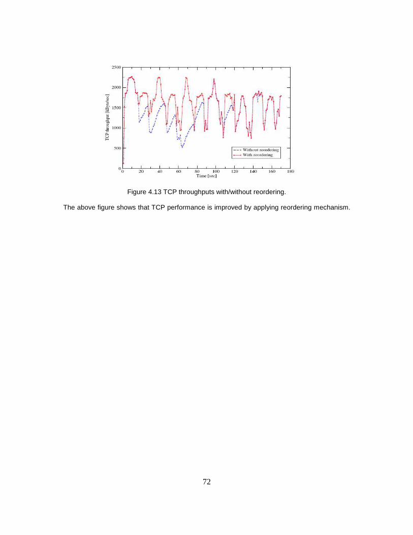
72
Figure 4.13 TCP throughputs with/without reordering.
The above figure shows that TCP performance is improved by applying reordering mechanism.
73
CHAPTER 5
HANDOVERS
This chapter covers in detail Inter RAT handovers. Specifically this chapter explains
handover from E-UTRAN to UTRAN with preparation, execution, and reject phase, UTRAN to
E-UTRAN with preparation, execution, and reject phase, E-UTRAN to GERAN with preparation,
execution, and reject phase, GERAN to E-UTRAN preparation, execution, and reject phase.
When an UE performs handover between E-UTRAN to GERAN/UTRAN it maps
parameter GUTI to an RAI, a P-TMSI, and a P-TMSI Signature, or vice versa in the case when
an UE handovers from GERAN/UTRAN to E-UTRAN. Before understanding this mapping
procedure between these parameters let us take a deep look to understand parameter GUTI.
GUTI (Globally Unique Temporary UE Identity) is identity which provides unambiguous
information about the UE, it does not provide UE’s or user’s permanent Identity in the EPS, it
instead provides identity of the network and MME connected to particular UE. GUTI comprises
of two main components one uniquely identifies the MME which allocated GUTI and second that
uniquely identifies the UE within MME that allocated GUTI. GUTI is constructed with the
combination of GUMMEI and M-TMSI. This GUMMEI (Globally Unique MME Identifier) is
constructed with the combination of Mobile Country Code (MCC), Mobile Network Code (MNC),
and MME Identifier (MMEI). The MMEI comprises of MME Group ID and MME Code.
Now let us understand mapping of these parameters when UE performs handover
operation from E-UTRAN to GERAN/UTRAN. In this scenario the mapping of GUTI shall be
done to the combination of RAI of GERAN/UTRAN and the P-TMSI,
E-UTRAN <MCC> maps to GERAN/UTRAN <MCC>
E-UTRAN <MNC> maps to GERAN/UTRAN <MNC>
E-UTRAN <MME Group ID> maps to GERAN/UTRAN <LAC>

74
E-UTRAN <MME Code> maps to GERAN/UTRAN <RAC> and is also copied into the 8 most
significant bits of the NRI field within the P-TMSI;
E-UTRAN <M-TMSI> maps as follows:
- 6 bits of the E-UTRAN <M-TMSI> starting at bit 29 and down to bit 24 are mapped into
bit 29 and down to bit 24 of the GERAN/UTRAN <P-TMSI>
- 16 bits of the E-UTRAN <M-TMSI> starting at bit 15 and down to bit 0 are mapped into
bit 15 and down to bit 0 of the GERAN/UTRAN <P-TMSI>
- and the remaining 8 bits of the E-UTRAN <M-TMSI> are mapped into the 8 MBS bits of
the <P-TMSI signature> field
Now in the case when UE performs handover operation from GERAN/UTRAN to E-UTRAN the
UE performs mapping from RAI and P-TMSI to GUTI to be sent to target MME. This mapping is
performed as follows:
GERAN/UTRAN <MCC> maps to E-UTRAN <MCC>
GERAN/UTRAN <MNC> maps to E-UTRAN <MNC>
GERAN/UTRAN <LAC> maps to E-UTRAN <MME Group ID>
GERAN/UTRAN <RAC> maps into bit 23 and down to bit 16 of the M-TMSI
The 8 MSBs of the GERAN/UTRAN <NRI> map to the MME Code.
GERAN/UTRAN <P-TMSI> maps as follows:
- 6 bits of the GERAN/UTRAN <P-TMSI> starting at bit 29 and down to bit 24 are
mapped into bit 29 and down to bit 24 of the E-UTRAN <M-TMSI>
- 16 bits of the GERAN/UTRAN <P-TMSI> starting at bit bit 15 and down to bit 0 are
mapped into bit 15 and down to bit 0 of the E-UTRAN <M-TMSI>.
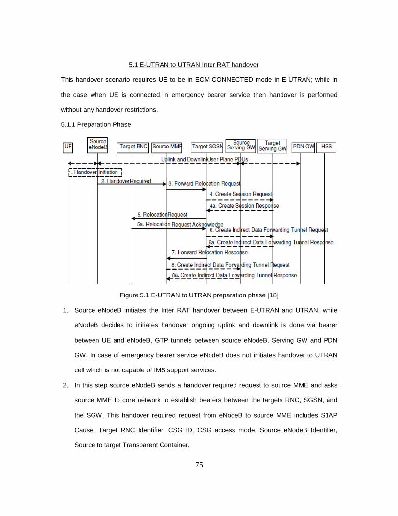
75
5.1 E-UTRAN to UTRAN Inter RAT handover
This handover scenario requires UE to be in ECM-CONNECTED mode in E-UTRAN; while in
the case when UE is connected in emergency bearer service then handover is performed
without any handover restrictions.
5.1.1 Preparation Phase
Figure 5.1 E-UTRAN to UTRAN preparation phase [18]
1. Source eNodeB initiates the Inter RAT handover between E-UTRAN and UTRAN, while
eNodeB decides to initiates handover ongoing uplink and downlink is done via bearer
between UE and eNodeB, GTP tunnels between source eNodeB, Serving GW and PDN
GW. In case of emergency bearer service eNodeB does not initiates handover to UTRAN
cell which is not capable of IMS support services.
2. In this step source eNodeB sends a handover required request to source MME and asks
source MME to core network to establish bearers between the targets RNC, SGSN, and
the SGW. This handover required request from eNodeB to source MME includes S1AP
Cause, Target RNC Identifier, CSG ID, CSG access mode, Source eNodeB Identifier,
Source to target Transparent Container.
76
3. Source MME utilizes the Target RNC identifier sent to it by eNodeB to determine the type
of handover requested by eNodeB, and then it contacts the target SGSN in order to do
resource allocation for the particular UE by sending a Forward Relocation Request which
includes IMSI, Target Identification, CSG ID, CSG membership Indication, MM Context,
PDN Connections, MME tunnel endpoint identifier for control plane, MME address for
control plane, Source to target Transparent Container, RAN Cause, MS Info Change
Reporting action in case when available, and ISR supported. This ISR supported indication
is sent by source MME to target SGSN if the source MME is capable of activating ISR
mode for UE. Source MME performs a check on the allowed CSG subscription for
particular UE in case when there is no data available or the CSG ID is expired then it
rejects the handover request with appropriate cause.
4. Target SGSN at this point decides if the Serving Gateway needs to be relocated , in the
case when SGW needs to be relocated target SGSN selects new target serving GW with
SGW selection function and requests this target SGW to create session by sending a
Create Session Request which includes IMSI, SGSN Tunnel endpoint Identifier for Control
Plane, SGSN Address for Control Plane, PDN GW address for user plane, PDN GW UL
TEID(s) for user plane, PDN GW address for control plane, protocol type over the serving
Network.
A. Serving GW responds to this request made by target SGSN by sending a Create
Session Response to it.
5. Target RNC in this step is requested by target SGSN to establish radio network resources
by the Relocation Request message. This message includes UE Identifier, Cause, CN
Domain Indicator, Integrity protection information, Encryption information, RAB to be setup
list, CSG ID, CSG Membership Indication, Source RNC to Target RNC Transparent
Container, Service Handover related information.
77
Service Handover related information is included by target SGSN in the case when service
area restrictions are present in order to limit the UE in connected mode to handover to the
RAT prohibited by access restrictions. Ciphering and integrity protection keys are present
in the message in order to prevent UE from having a new Authentication and Key
Agreement procedure. Cause indicated in the message from target SGSN to target RNC
indicates the cause RAT sent by source MME to target SGSN. In the case when the target
cell is in the closed subscriber group it verifies CSG ID provided by the target SGSN if it
does not matches then it rejects handover with appropriate cause of the rejection.
A. Target RNC in this step responds to target SGSN’s request with a Relocation Request
Acknowledge after allocating the resources were requested. As soon as target RNC
sends this acknowledge towards target SGSN it becomes ready to accept any downlink
GTP PDUs from serving GW.
6. In the case when SGW is relocated and Indirect forwarding applies then target SGSN
sends a Create Indirect Data Forwarding Tunnel Request message to serving GW.
A. Serving GW responds to this request message with a Create Indirect Data Forwarding
Tunnel Response which includes cause, Serving GW address, and TEID(s) for data
forwarding to the target SGSN
7. In this step target SGSN responds to source MEM with Forward Relocation Response
which includes parameters like cause, SGSN Tunnel Endpoint Identifier for Control Plane,
SGSN Address for Control Plane, Target to source Transparent Container, RAB Setup
Information, address(s) and TEID(s) used for User Traffic Data Forwarding, Serving GW
change Indication.
8. In the case when the indirect forwarding applies then Source MME sends the message
Create Indirect Data Forwarding Tunnel Request and it responds for the same with Create
Indirect Data Forwarding Tunnel Response. In the case when SGW does not support this it
rejects the request with an appropriate cause to source MME.

78
5.1.2 Execution Phase
Figure 5.2 E-UTRAN to UTRAN Execution phase [18]
1. Source MME sends a message to source eNodeB as Handover Command to complete the
preparation phase. The source eNodeB initiates the Data forwarding it may directly go to
target RNC or alternatively via SGW as decided by source MME and target SGSN in the
preparation phase.

79
2. Source eNodeB commands UE to perform handover with HO message from E-UTRAN.
This message provides UE with transparent container including radio aspect parameters
that the target RNC has set up in the preparation phase. Now UE associates it bearer IDs
to the respective RABs and shall suspend any uplink transmission of the user plane.
3. Void.
4. UE in this step moves to the target access network that is UTRAN (3G) system and
performs handover with specified parameters in the preparation procedure.
5. After parameters like RNC-ID and S-RNTI are successfully exchanged between UE and
target RNC it sends a Relocation Complete Message to the target SGSN. This enables
target SGSN to receive data from target RNC and directly forward it to the SGW.
6. When SGSN realizes that UE has camped on UTRAN and has accepted the handover
message from E-UTRAN then it sends a Forward Relocation Complete Notification to
source MME. This message includes information about ISR if it is activated or not, in the
case when ISR is shown activated to source MME by target SGSN it maintains the UE
context and activates ISR mode for UE and this case is possible only when the Serving
GW is not changed. The source MME starts a Timer to supervise the UE contexts in
source eNodeB and source Serving GW. MME deletes all the EPS bearers if the ISR
mode is indicated as not activated and timer also expires. In the case when Serving GW
change is indicated MME does not hold any UE related context information, in the case of
SGW change source SGW is notified about it and it shall delete the bearer resources.
7. Handover procedure is completed by target SGSN by informing the SGW that all the EPS
bearers for the particular UE are now handled by target SGSN by sending a Modify bearer
Request to SGW. This request includes SGSN Tunnel Endpoint Identifier for Control
Plane, NSAPI(s), and SGSN Address for control Plane, SGSN Address(s) and TEID(s) for
User Traffic for the accepted EPS bearer or RNC Address(s), RAT Type, and ISR
Activated. SGSN includes user location information in this message if it is requested by

80
PDN GW. In the case when ISR mode is not activated and SGW is not changed then it
sends a delete bearer context to other CN node which had bearer resources on the SGW
reserved.
8. SGW sends a Modify Bearer Request to PDN GW per PDN connection in case when the
SGW is changed or RAT type has changed to help PDN GW in charging process
according to the Rat type UE is using or any other services in which RAT type plays role in
PDN GW. PDN GW acknowledges SGW with the Modify Bearer Response and updates
its own context fields in case when SGW is relocated or changed in this handover process.
9. SGW responds to target SGSN with the Modify Bearer Response and after this user plane
path is established for all EPS Bearers. This response includes Cause, Serving gateway
Tunnel Endpoint Identifier for Control Plane, Serving GW Address for Control Plane,
Protocol Configuration Options. In the case when SGW is not changed it sends end marker
packets on old path after switching the path.
10. Since the routing area is not registered with the network for UE it initiates Routing Area
Update Procedure with the target SGSN and this informs target SGSN that the UE is
located in new routing area.
11. As the timer in source MME expires it sends the Release Resources message to source
eNodeB which releases resources for that particular UE. Also source MME sends Delete
Session Request to source SGW in the case when there is change or relocation of the
SGW occurs. The source SGW responds to the source MME with Delete Session
Response and also deletes bearer resources on the other old CN node.
12. In the case when indirect forwarding was used and timer in the source MME expires it
sends a Delete Indirect Data Forwarding Tunnel Request message to the SGW and
requests it to release resources for indirect forwarding.

81
13. Since SGW is relocated and timer started at target SGSN expires is sends a Delete
Indirect Data Forwarding Tunnel Request message to target SGW to release resources
used in indirect forwarding.
5.1.3 Reject Phase
Figure 5.3 Inter RAT handover Reject [18]
1. Source eNodeB initiates the Inter RAT handover between E-UTRAN and UTRAN, while
eNodeB decides to initiates handover ongoing uplink and downlink is done via bearer
between UE and eNodeB, GTP tunnels between source eNodeB, Serving GW and PDN
GW. In case of emergency bearer service eNodeB does not initiates handover to UTRAN
cell which is not capable of IMS support services.
2. In this step source eNodeB sends a handover required request to source MME and asks
source MME to core network to establish bearers between the targets RNC, SGSN, and
the SGW. This handover required request from eNodeB to source MME includes S1AP
Cause, Target RNC Identifier, CSG ID, CSG access mode, Source eNodeB Identifier,
Source to target Transparent Container.
3. Source MME utilizes the Target RNC identifier sent to it by eNodeB to determine the type
of handover requested by eNodeB, and then it contacts the target SGSN in order to do

82
resource allocation for the particular UE by sending a Forward Relocation Request which
includes IMSI, Target Identification, CSG ID, CSG membership Indication, MM Context,
PDN Connections, MME tunnel endpoint identifier for control plane, MME address for
control plane, Source to target Transparent Container, RAN Cause, MS Info Change
Reporting action in case when available, and ISR supported. This ISR supported
indication is sent by source MME to target SGSN if the source MME is capable of
activating ISR mode for UE. Source MME performs a check on the allowed CSG
subscription for particular UE in case when there is no data available or the CSG ID is
expired then it rejects the handover request with appropriate cause.
4. Target SGSN at this point decides if the Serving Gateway needs to be relocated , in the
case when SGW needs to be relocated target SGSN selects new target serving GW with
SGW selection function and requests this target SGW to create session by sending a
Create Session Request which includes IMSI, SGSN Tunnel endpoint Identifier for Control
Plane, SGSN Address for Control Plane, PDN GW address for user plane, PDN GW UL
TEID(s) for user plane, PDN GW address for control plane, protocol type over the serving
Network.
B. Serving GW responds to this request made by target SGSN by sending a Create
Session Response to it.
5. Target RNC in this step is requested by target SGSN to establish radio network resources
by the Relocation Request message. This message includes UE Identifier, Cause, CN
Domain Indicator, Integrity protection information, Encryption information, RAB to be setup
list, CSG ID, CSG Membership Indication, Source RNC to Target RNC Transparent
Container, Service Handover related information.
Service Handover related information is included by target SGSN in the case when service
area restrictions are present in order to limit the UE in connected mode to handover to the
RAT prohibited by access restrictions. Ciphering and integrity protection keys are present

83
in the message in order to prevent UE from having a new Authentication and Key
Agreement procedure. Cause indicated in the message from target SGSN to target RNC
indicates the cause RAT sent by source MME to target SGSN. In the case when the target
cell is in the closed subscriber group it verifies CSG ID provided by the target SGSN if it
does not matches then it rejects handover with appropriate cause of the rejection.
6. Now in this case target RNC fails to allocate requested resources it responds with a
Relocation Failure message to the Target SGSN. As target SGSN receives this message it
clears all the reserved resources for the particular UE.
7. Target SGW receives Delete Session Request from the target SGSN and it responds with
Delete Session Response message to target SGSN. This is done in the case when SGW
is relocated.
8. Source MME is notified about the rejection in Forward Relocation response from target
SGSN.
9. Now as the source MME realizes the failure of the handover procedure it notifies source
eNodeB about the same by sending a Handover Preparation Failure message to source
eNodeB.
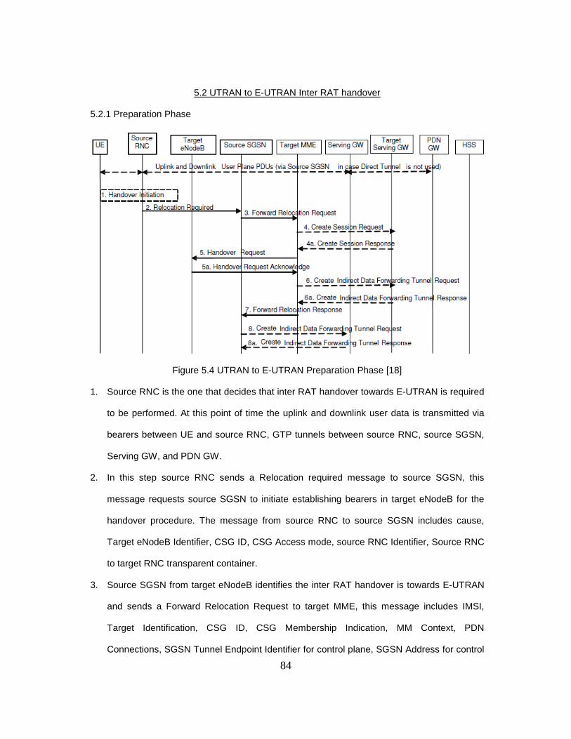
84
5.2 UTRAN to E-UTRAN Inter RAT handover
5.2.1 Preparation Phase
Figure 5.4 UTRAN to E-UTRAN Preparation Phase [18]
1. Source RNC is the one that decides that inter RAT handover towards E-UTRAN is required
to be performed. At this point of time the uplink and downlink user data is transmitted via
bearers between UE and source RNC, GTP tunnels between source RNC, source SGSN,
Serving GW, and PDN GW.
2. In this step source RNC sends a Relocation required message to source SGSN, this
message requests source SGSN to initiate establishing bearers in target eNodeB for the
handover procedure. The message from source RNC to source SGSN includes cause,
Target eNodeB Identifier, CSG ID, CSG Access mode, source RNC Identifier, Source RNC
to target RNC transparent container.
3. Source SGSN from target eNodeB identifies the inter RAT handover is towards E-UTRAN
and sends a Forward Relocation Request to target MME, this message includes IMSI,
Target Identification, CSG ID, CSG Membership Indication, MM Context, PDN
Connections, SGSN Tunnel Endpoint Identifier for control plane, SGSN Address for control
85
plane, Source to Target Transparent Container, RAN cause, MS Info Change Reporting
action if available, ISR support Indication. In the case when ISR support is activated that
means source SGSN is capable of activating ISR mode this message is sent to target
MME that maintains ISR for the UE. Target MME sends the NAS ciphering and integrity
protection algorithms to use to UE. Target MME receives APN restriction of each bearer in
the Forward Relocation Request and determines and stores this new maximum APN
restriction value.
4. Target MME decides if the SGW relocation is to be performed because of PLMN change,
in the case when SGW is relocated target MME selects target SGW and sends the Create
Session Request to target SGW. This message includes IMSI, MME Address and TEID,
MME Tunnel Endpoint Identifier for Control Plane, PDN GW address for control plane,
PDN GW TEID(s) for control plane, the protocol type over S5/S8, and serving network.
A. Target Serving GW responds to target MME by sending Create Session Response
message; this message includes SGW Address(s) for user plane, SGW UL TEID(s) for
user plane, SGW Address for control plane, and SGW TEID for control plane.
5. Target MME sends a Handover Request message to target eNodeB, this message
requests target eNodeB to establish the bearers for a particular UE performing handover.
This message includes UE Identifier, S1AP Cause, KeNB, allowed AS integrity Protection
and ciphering algorithms, NAS security parameters to E-UTRAN, EPS bearers to be setup
list, CSG ID, CSG Membership Indication, Source to target Transparent Container.
A. Target eNodeB allocates the requested bearers in the message from target MME and
responds the same with handover Request Acknowledge. In the case when number
radio bearers are different in source to target transparent container it will allocate the
number of bearers according to request by target MME. As eNodeB sends this
acknowledge it becomes ready to accept downlink GTP PDUs from the SGW.

86
6. In the case when Indirect Forwarding and Relocation of SGW is supported target MME
sends a Create Indirect Data Forwarding Tunnel Request message to SGW.
A. SGW responds to target MME with a Create Indirect data Forwarding Tunnel
Response.
7. Target MME responds to the request made by source SGSN in step 3 with a Forward
Relocation Response message towards source SGSN, this message includes Cause, List
of Set Up RABs, EPS Bearers setup list, MME Tunnel Endpoint Identifier for control plane,
RAN cause, MME address for control plane, Target to Source Transparent Container,
Address(s) and TEID(s) for data Forwarding, SGW change indication.
8. Source SGSN in case of Indirect Forwarding sends a Create Indirect Data Forwarding
Tunnel Request to SGW used n this indirect process.
A. SGW responds to this request by sending a Create Indirect Data Forwarding Tunnel
Response to source SGW.

87
5.2.2 Execution Phase
Figure 5.5 UTRAN to E-UTRAN Execution phase [18]
1. In the Execution phase Source SGSN sends a relocation command to Source RNC as mark
of completion of the preparation phase. This relocation command includes Source RNC to
Target RNC Transparent Container, RABs to be released List, RABs Subject to data
forwarding list.
88
2. Source RNC commands UE to perform Handover operation by sending HO message from
UTRAN. This message commands UE to perform handover to Target eNodeB, this
message provides UE with the specific parameters that eNodeB has already setup for UE in
preparation phase. Source RNC at this point initiate data forwarding towards target eNodeB
directly or indirectly through serving GW as decided in preparation phase.
3. Void
4. UE follows E-UTRAN access procedures and initiates the connection towards E-UTRAN as
initial attach procedure with parameters setup in preparation phase between UTRAN and E-
UTRAN.
5. As UE get access to target eNodeB it sends a HO complete message for E-UTRAN to
source eNodeB.
6. eNodeB informs target MME about the handover performed by UE with a Handover Notify
message towards target MME.
7. When target MME realizes that UE has camped on E-UTRAN and has accepted the
handover message from UTRAN then it sends a Forward Relocation Complete Notification
to source SGSN. This message includes information about ISR if it is activated or not, in the
case when ISR is shown activated to source SGSN by target MME it maintains the UE
context and activates ISR mode for UE and this case is possible only when the Serving GW
is not changed. The source SGSN starts a Timer to supervise the UE contexts in source
RNC and source Serving GW. Source SGSN responds to this message with acknowledge
and target MME starts a timer upon reception of this ack from source SGSN in the case
when indirect forwarding is applied.
8. Target MME notifies target SGW (if SGW is relocated or else it would be SGW instead of
target SGW) that Inter-RAT handover procedure is complete and target MME will be now
responsible to hold all UE related bearers ahead. In order to perform this operation target
MME sends a Modify Bearer Request to target SGW per PDN connection which includes

89
Cause, MME Tunnel Endpoint Identifier for Control Plane, EPS Bearer ID, MME Address for
control plane, eNodeB address and TEID(s) for user traffic, RAT type, and ISR activated if
applicable. IN the case when ISR mode is not activated this is possible only when SGW is
not relocated then SGW sends Delete Bearer Request to other CN node that has bearer
resources reserved on SGW.
9. SGW sends a Modify Bearer Request to PDN GW per PDN connection in case when the
SGW is changed or RAT type has changed to help PDN GW in charging process according
to the Rat type UE is using or any other services in which RAT type plays role in PDN GW.
PDN GW acknowledges SGW with the Modify Bearer Response and updates its own
context fields in case when SGW is relocated or changed in this handover process.
10. SGW responds to target MME with the Modify Bearer Response and after this user plane
path is established for all EPS Bearers. This response includes Cause, Serving gateway
Tunnel Endpoint Identifier for Control Plane, Serving GW Address for Control Plane,
Protocol Configuration Options. In the case when SGW is not changed it sends end marker
packets on old path after switching the path.
11. At this point of time UE initiate Tracking Area Update Procedure towards E-UTRAN, since
target MME is aware of the Handover operation just performed with particular UE so is
performs only a subset of the tracking are update procedure.
12. The timer in source SGSN which was started in step 7 gets expired source SGSN performs
Iu release procedure in order to delete all its resources towards source RNC. Source RNC
also deletes its resources for particular UE and responds to source SGSN with Iu Release
Complete Message.
13. In the case when Indirect Data Forwarding Tunnel is used as the timer in source SGSN is
expired it sends a message to SGW to delete the temporary bearers/resources related to
indirect tunneling.

90
14. In scenario when SGW is relocated and Indirect tunnel is used for data forwarding and timer
in target MME expires it sends a message to target SGW to release temporary resources
used in indirect tunneling.
5.2.3 Reject Phase
Figure 5.6 UTRAN to E-UTRAN Reject phase [18]
1. Source RNC is the one that decides that inter RAT handover towards E-UTRAN is required
to be performed. At this point of time the uplink and downlink user data is transmitted via
bearers between UE and source RNC, GTP tunnels between source RNC, source SGSN,
Serving GW, and PDN GW.
2. In this step source RNC sends a Relocation required message to source SGSN, this
message requests source SGSN to initiate establishing bearers in target eNodeB for the
handover procedure. The message from source RNC to source SGSN includes cause,
Target eNodeB Identifier, CSG ID, CSG Access mode, source RNC Identifier, Source RNC
to target RNC transparent container.
3. Source SGSN from target eNodeB identifies the inter RAT handover is towards E-UTRAN
and sends a Forward Relocation Request to target MME, this message includes IMSI,
Target Identification, CSG ID, CSG Membership Indication, MM Context, PDN Connections,

91
SGSN Tunnel Endpoint Identifier for control plane, SGSN Address for control plane, Source
to Target Transparent Container, RAN cause, MS Info Change Reporting action if available,
ISR support Indication. In the case when ISR support is activated that means source SGSN
is capable of activating ISR mode this message is sent to target MME that maintains ISR for
the UE. Target MME sends the NAS ciphering and integrity protection algorithms to use to
UE. Target MME receives APN restriction of each bearer in the Forward Relocation
Request and determines and stores this new maximum APN restriction value.
4. Target MME decides if the SGW relocation is to be performed because of PLMN change, in
the case when SGW change is occurred target MME selects target SGW and sends the
Create Session Request to target SGW. This message includes IMSI, MME Address and
TEID, MME Tunnel Endpoint Identifier for Control Plane, PDN GW address for control
plane, PDN GW TEID(s) for control plane, the protocol type over S5/S8, and serving
network.
A. Target Serving GW responds to target MME by sending Create Session Response
message; this message includes SGW Address(s) for user plane, SGW UL TEID(s) for
user plane, SGW Address for control plane, and SGW TEID for control plane.
5. Target MME sends a Handover Request message to target eNodeB, this message requests
target eNodeB to establish the bearers for a particular UE performing handover. This
message includes UE Identifier, S1AP Cause, KeNB, allowed AS integrity Protection and
ciphering algorithms, NAS security parameters to E-UTRAN, EPS bearers to be setup list,
CSG ID, CSG Membership Indication, Source to target Transparent Container.
6. Now in this case target eNodeB fails to allocate requested resources it responds with a
Relocation Failure message to the Target MME. As target MME receives this message it
clears all the reserved resources for the particular UE.

92
7. Target SGW receives Delete Session Request from the target MME and it responds with
Delete Session Response message to target MME. This is done in the case when SGW is
relocated.
8. Source SGSN is notified about the rejection in Forward Relocation response from target
MME.
9. Now as the source SGSN realizes the failure of the handover procedure it notifies source
RNC about the same by sending a Handover Preparation Failure message to source RNC.
5.3 E-UTRAN to GERAN Inter RAT handover
5.3.1 Preparation Phase
Figure 5.7 E-UTRAN to GERAN Preparation Phase [18]
1. Source initiates the handover procedure from E-UTRAN to GERAN (2G) system. At this
point of time the user data is transmitted via bearers between UE and Source eNodeB,
GTP Tunnel(s) between Source eNodeB, SGW and PDN GW.
2. Source eNodeB in order to initiate handover procedure it sends a Handover required
message to source MME, this message includes S1AP Cause, target System Identifier,
Source eNodeB Identifier, Source to Target Transparent container. This message

93
requests source MME and CN nodes to establish required bearer settings in the target
system entities like target BSS, target SGSN, and the Serving GW.
3. Source MME utilizes the Target RNC identifier sent to it by eNodeB to determine the
type of handover requested by eNodeB, and then it contacts the target SGSN in order
to do resource allocation for the particular UE by sending a Forward Relocation
Request which includes IMSI, Target Identification, MM Context, PDN Connections,
MME tunnel endpoint identifier for control plane, MME address for control plane, Source
to target Transparent Container, Packet Flow ID, XID parameters, RAN Cause, and ISR
supported. This ISR supported indication is sent by source MME to target SGSN if the
source MME is capable of activating ISR mode for UE. IN the case when ISR mode is
activated it should be notified to target SGSN that maintains ISR for the UE when this
SGSN is serving the target.
4. Target SGSN at this point decides if the Serving Gateway needs to be relocated , in the
case when SGW needs to be relocated target SGSN selects new target serving GW
with SGW selection function and requests this target SGW to create session by sending
a Create Session Request which includes IMSI, SGSN Tunnel endpoint Identifier for
Control Plane, SGSN Address for Control Plane, PDN GW address for user plane, PDN
GW UL TEID(s) for user plane, PDN GW address for control plane, protocol type over
the serving Network.
A. Serving GW responds to this request made by target SGSN by sending a Create
Session Response to it.
5. As in the forward relocation request target SGSN establishes the EPS bearer context(s)
in required order it now request target BSS to establish required resources for this
handover operation of UE from E-UTRAN to GERAN by sending PS Handover Request
which includes Local TLLI, IMSI Cause, Target Cell Identifier, PFCs to be set-up list,

94
Source RNC to Target BSS Transparent Container, NAS container fro handover,
Reliable Inter Rat Handover Info.
A. As target BSS receives this request it allocates the required resources and responds
to the target SGSN as PS Handover Request Acknowledge, after sending this
message target BSS is ready to receive downlink LLC PDUs from the target SGSN.
6. In the case when Indirect Forwarding is applicable to the scenario and relocation of
SGW occur then target SGSN requests SGW used in indirect packet forwarding by
sending a Create Indirect Data Forwarding.
A. SGW responds to this request from target SGSN with an Indirect Data Forwarding
Tunnel Response message to target SGSN.
7. Source MME receives forward relocation response from source SGSN which includes
parameters like Cause, SGSN Tunnel Endpoint Identifier for Control Plane, SGSN
Address for Control Plane, Target to Source Transparent Container, RAN Cause, List of
set-up PFIs, Address(s) and TEID(s) for User Traffic Forwarding, Serving GW change
indication.
8. In the case when Indirect Forwarding is applied then serving GW receives a Create
Indirect Data Forwarding Tunnel Request by source MME.
A. If SGW supports the Indirect Data Forwarding then it responds to source MME with a
Create Indirect Data Forwarding Tunnel Response or otherwise it returns the
message with appropriate cause to it.

95
5.3.2 Execution Phase
Figure 5.8 E-UTRAN to GERAN Execution Phase [18]
96
1. Source eNodeB receives Handover command from source MME as the completion of
the preparation phase; this message includes Target to Source Transparent container,
E-RABs to release List, Bearers Subject to Data Forwarding List, S1AP Cause.
2. UE receives this handover command from source eNodeB as the E-UTRAN HO
Command message. As soon as UE receives this HO command message from E-
UTRAN it associates its bearers IDs to respective PFIs and suspends any uplink
transmission to the user plane.
3. VOID
4. As UE receives HO command from E-UTRAN it moves to the target GERAN system
and performs execution of the parameters provided to it by the E-UTRAN preparation
phase. (This step basically performs initial attach procedure towards GERAN).
5. As UE realizes it has got access to the cell using access bursts it sends a XID response
to target SGSN via target BSS. UE after sending this XID response it resumes sending
user data for which radio resources are allocated in target cell.
6. Target BSS waits till it receives first correct RLC/MAC block from UE as soon as it
receives this block correctly it informs target SGSN by sending the message PS
Handover Complete. This message includes IMSI, and Local TLLI, request for Inter
RAT Handover Info.
7. In this step target BSS sends XID Response to target SGSN.
8. Now target SGSN is aware of the fact that UE has camped on GERAN access system
and had performed handover as requested by E-UTRAN so it notifies same to target
MME by sending the Forward Relocation Complete Notification message. In the case
when ISR mode active is indicated in the message then MME retains the UE related
bearer contexts and activates ISR, this is possible only when SGW does not relocates.
Now source MME activates a timer to supervise resources in source eNodeB and
source SGW (SGW in case when SGW is not relocated). Source MME now
97
acknowledges target SGSN by sending Forward Relocation Complete Acknowledge
message. Upon reception of this acknowledge source SGSN starts a timer if the target
SGSN allocated SGW resources for indirect forwarding.
9. Target SGSN sends a Modify Bearer Request per PDN connection to Serving GW. By
sending this message target SGSN completes handover procedure and informs SGW
that all the EPS bearers are handled by target SGSN. This Modify Bearer Request
includes SGSN Tunnel Endpoint Identifier for Control Plane, NSA PI(s), SGSN Address
for Control Plane, SGSN Address(s) and TEID(s) for User Traffic for the accepted EPS
bearers and RAT type, ISR Activated. In the case hen this message indicates ISR
mode is not activated and SGW change is not performed then the SGW deletes any
ISR resources by sending a Delete Bearer Request to the other CN node.
10. SGW sends a Modify Bearer Request to PDN GW per PDN connection in case when
the SGW is changed or RAT type has changed to help PDN GW in charging process
according to the Rat type UE is using or any other services in which RAT type plays
role in PDN GW. PDN GW acknowledges SGW with the Modify Bearer Response and
updates its own context fields in case when SGW is relocated or changed in this
handover process.
11. Modify Bearer Response is sent as acknowledgement from SGW to Target SGSN at
this step user plane path is established for all EPS bearers contexts between the UE,
Target BSS, Target SGSN, SGW and PDN GW. This response includes Cause, SGW
Tunnel Endpoint Identifier for Control Plane, SGW address for Control Plane, Protocol
Configuration Options.
12. VOID
13. As UE completes this reconfiguration procedure it initiates Routing Area Update
procedure towards target SGSN, now since target SGSN already knows handover
98
procedure done for particular UE it specifically excludes the context transfer procedures
between source MME and target SGSN.
A. Target SGSN sends a PS Handover Complete Acknowledge message to target
BSS, as soon as target BSS receives his message it sets the Reliable Inter RAT
Handover to ‘1’.
14. Now a timer was started in source MME to supervise resources in source eNodeB now
when the timer expires source MME sends a Release Resources to source eNodeB for
particular UE. In the case SGW is changed then source MME notifies same to source
SGW in order to delete the EPS bearer resources. SGW further acknowledge this
notification for source MME by sending Delete Session Response message.
15. In the case when Indirect Data Forwarding Tunnel is used as the timer in source MME
is expired it sends a message to SGW to delete the temporary bearers/resources
related to indirect tunneling.
16. In scenario when SGW is relocated and Indirect tunnel is used for data forwarding and
timer in target SGSN expires it sends a message to target SGW to release temporary
resources used in indirect tunneling.
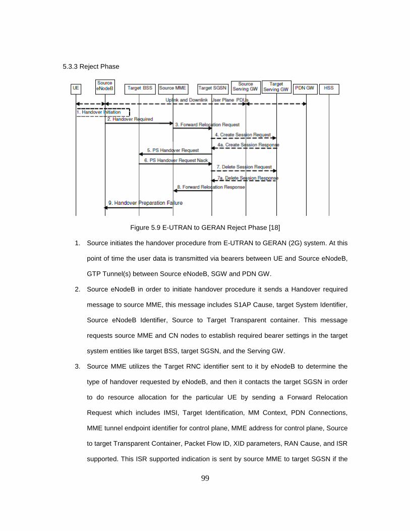
99
5.3.3 Reject Phase
Figure 5.9 E-UTRAN to GERAN Reject Phase [18]
1. Source initiates the handover procedure from E-UTRAN to GERAN (2G) system. At this
point of time the user data is transmitted via bearers between UE and Source eNodeB,
GTP Tunnel(s) between Source eNodeB, SGW and PDN GW.
2. Source eNodeB in order to initiate handover procedure it sends a Handover required
message to source MME, this message includes S1AP Cause, target System Identifier,
Source eNodeB Identifier, Source to Target Transparent container. This message
requests source MME and CN nodes to establish required bearer settings in the target
system entities like target BSS, target SGSN, and the Serving GW.
3. Source MME utilizes the Target RNC identifier sent to it by eNodeB to determine the
type of handover requested by eNodeB, and then it contacts the target SGSN in order
to do resource allocation for the particular UE by sending a Forward Relocation
Request which includes IMSI, Target Identification, MM Context, PDN Connections,
MME tunnel endpoint identifier for control plane, MME address for control plane, Source
to target Transparent Container, Packet Flow ID, XID parameters, RAN Cause, and ISR
supported. This ISR supported indication is sent by source MME to target SGSN if the

100
source MME is capable of activating ISR mode for UE. IN the case when ISR mode is
activated it should be notified to target SGSN that maintains ISR for the UE when this
SGSN is serving the target.
4. Target SGSN at this point decides if the Serving Gateway needs to be relocated , in the
case when SGW needs to be relocated target SGSN selects new target serving GW
with SGW selection function and requests this target SGW to create session by sending
a Create Session Request which includes IMSI, SGSN Tunnel endpoint Identifier for
Control Plane, SGSN Address for Control Plane, PDN GW address for user plane, PDN
GW UL TEID(s) for user plane, PDN GW address for control plane, protocol type over
the serving Network.
A. Serving GW responds to this request made by target SGSN by sending a Create
Session Response to it.
5. As in the forward relocation request target SGSN establishes the EPS bearer context(s)
in required order it now request target BSS to establish required resources for this
handover operation of UE from E-UTRAN to GERAN by sending PS Handover Request
which includes Local TLLI, IMSI Cause, Target Cell Identifier, PFCs to be set-up list,
Source RNC to Target BSS Transparent Container, NAS container fro handover,
Reliable Inter Rat Handover Info.
6. Now in this case target BSS fails to allocate requested resources it responds with a PS
Handover Request NACK (Cause) message to the Target SGSN. As target SGSN
receives this message it clears all the reserved resources for the particular UE.
7. Target SGW receives Delete Session Request from the target SGSN and it responds
with Delete Session Response message to target SGSN. This is done in the case when
SGW is relocated.
8. Source MME is notified about the rejection in Forward Relocation response from target
SGSN.

101
9. Now as the source MME realizes the failure of the handover procedure it notifies source
eNodeB about the same by sending a Handover Preparation Failure message to source
eNodeB.
5.4 GERAN to E-UTRAN Inter RAT handover
5.4.1 Preparation Phase
Figure 5.10 GERAN to E-UTRAN preparation phase [18]
1. Source BSS initiates the handover procedure towards the E-UTRAN, at this point of time
the uplink and downlink user data is transmitted on the bearers between UE and source
BSS, BSSGP PFC tunnel(s) between source BSS and source SGSN, GTP tunnel(s)
between Source SGSN, Serving GW and PDN GW.
2. In order to perform the Inter Rat handover operation source BSS requests source SGSN
to establish resources in target eNodeB, target MME, and SGW by sending PS handover
required message. This message includes TLLI, Cause, Source Cell Identifier, Target
eNodeB Identifier, Source BSS to target RNC transparent container and active PFCs list.
3. Handover operation is towards E-UTRAN is determined by source SGSN by target eNodeB
Identifier and sends a Forward Relocation request to target MME. This message initiates
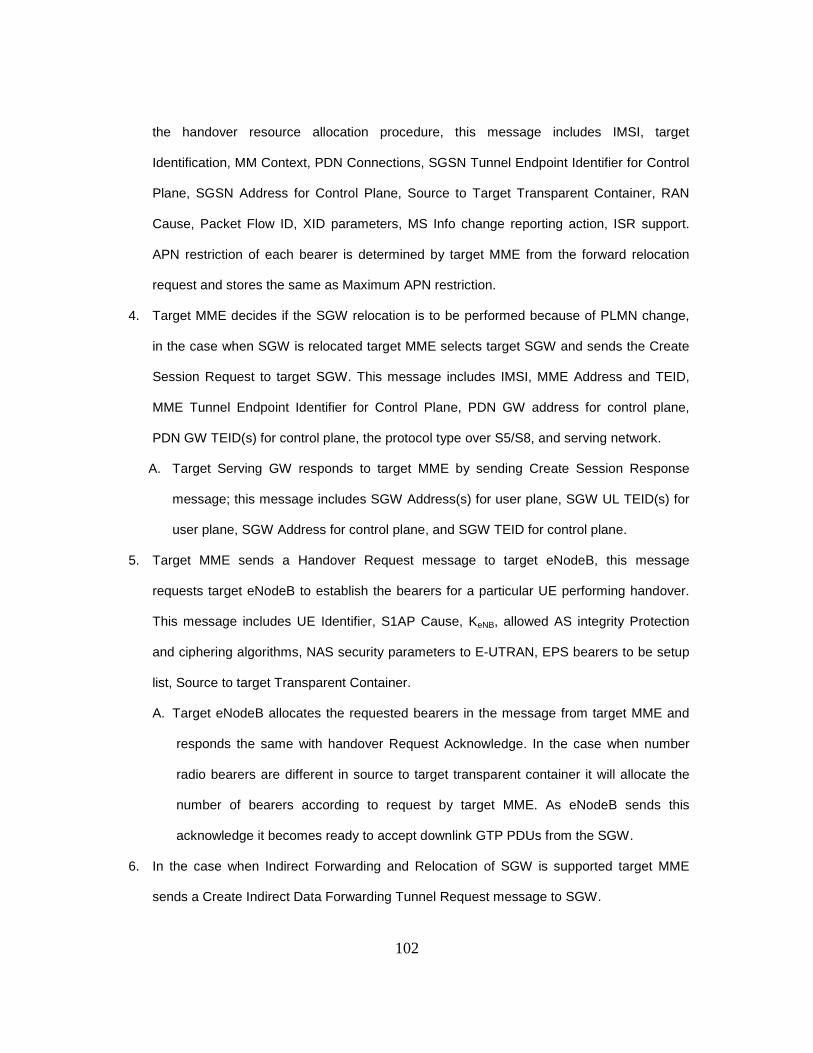
102
the handover resource allocation procedure, this message includes IMSI, target
Identification, MM Context, PDN Connections, SGSN Tunnel Endpoint Identifier for Control
Plane, SGSN Address for Control Plane, Source to Target Transparent Container, RAN
Cause, Packet Flow ID, XID parameters, MS Info change reporting action, ISR support.
APN restriction of each bearer is determined by target MME from the forward relocation
request and stores the same as Maximum APN restriction.
4. Target MME decides if the SGW relocation is to be performed because of PLMN change,
in the case when SGW is relocated target MME selects target SGW and sends the Create
Session Request to target SGW. This message includes IMSI, MME Address and TEID,
MME Tunnel Endpoint Identifier for Control Plane, PDN GW address for control plane,
PDN GW TEID(s) for control plane, the protocol type over S5/S8, and serving network.
A. Target Serving GW responds to target MME by sending Create Session Response
message; this message includes SGW Address(s) for user plane, SGW UL TEID(s) for
user plane, SGW Address for control plane, and SGW TEID for control plane.
5. Target MME sends a Handover Request message to target eNodeB, this message
requests target eNodeB to establish the bearers for a particular UE performing handover.
This message includes UE Identifier, S1AP Cause, KeNB, allowed AS integrity Protection
and ciphering algorithms, NAS security parameters to E-UTRAN, EPS bearers to be setup
list, Source to target Transparent Container.
A. Target eNodeB allocates the requested bearers in the message from target MME and
responds the same with handover Request Acknowledge. In the case when number
radio bearers are different in source to target transparent container it will allocate the
number of bearers according to request by target MME. As eNodeB sends this
acknowledge it becomes ready to accept downlink GTP PDUs from the SGW.
6. In the case when Indirect Forwarding and Relocation of SGW is supported target MME
sends a Create Indirect Data Forwarding Tunnel Request message to SGW.

103
A. SGW responds to target MME with a Create Indirect data Forwarding Tunnel
Response.
7. Target MME responds to the request made by source SGSN in step 3 with a Forward
Relocation Response message towards source SGSN, this message includes Cause, List
of Set Up RABs, EPS Bearers setup list, MME Tunnel Endpoint Identifier for control plane,
RAN cause, MME address for control plane, Target to Source Transparent Container,
Address(s) and TEID(s) for data Forwarding, SGW change indication.
8. Source SGSN in case of Indirect Forwarding sends a Create Indirect Data Forwarding
Tunnel Request to SGW used n this indirect process.
A. SGW responds to this request by sending a Create Indirect Data Forwarding Tunnel
Response to source SGW.
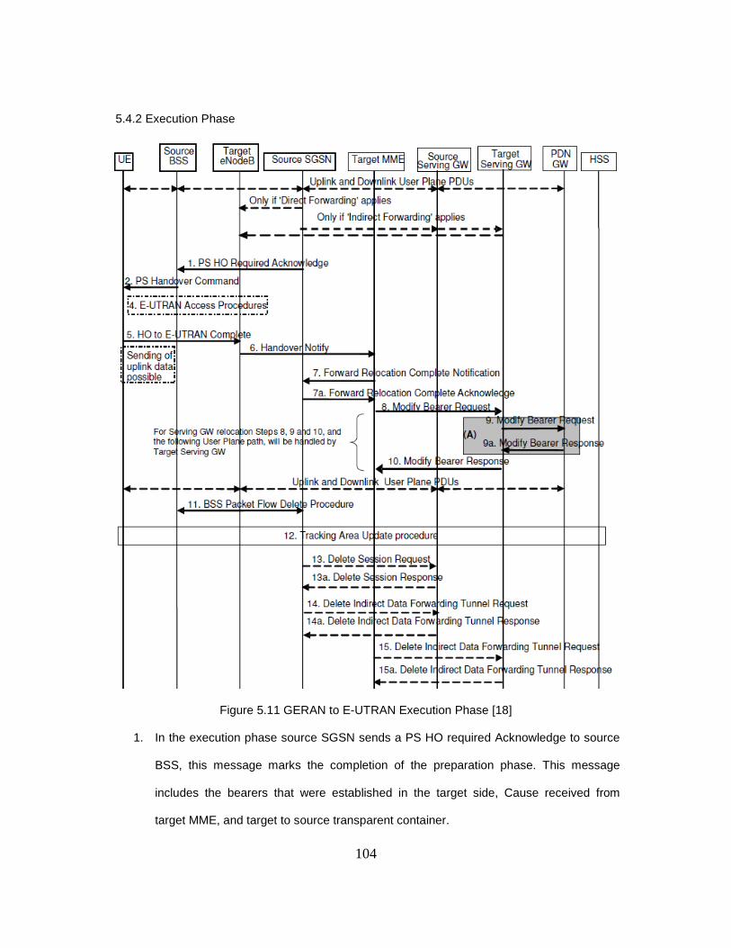
104
5.4.2 Execution Phase
Figure 5.11 GERAN to E-UTRAN Execution Phase [18]
1. In the execution phase source SGSN sends a PS HO required Acknowledge to source
BSS, this message marks the completion of the preparation phase. This message
includes the bearers that were established in the target side, Cause received from
target MME, and target to source transparent container.
105
2. Source BSS upon reception of the acknowledge message from source SGSN sends a
PS handover Command towards the UE requesting UE to perform handover towards
target eNodeB.
3. VOID
4. UE after receiving handover command perform access procedure towards target
eNodeB in order to camp on E-UTRAN. This access procedure was explained in detail
in attach procedure part of report.
5. As UE gets access towards E-UTRAN after performing access procedure it sends a HO
to E-UTRAN Complete message to target eNodeB.
6. Target eNodeB after receiving this message in step 5 realizes that UE has attached
itself to target eNodeB so it informs target MME about the same by sending Handover
message which includes TAI and ECGI.
7. When target MME realizes that UE has camped on E-UTRAN and has accepted the
handover message from UTRAN then it sends a Forward Relocation Complete
Notification to source SGSN. This message includes information about ISR if it is
activated or not, in the case when ISR is shown activated to source SGSN by target
MME it maintains the UE context and activates ISR mode for UE and this case is
possible only when the Serving GW is not changed. The source SGSN starts a Timer to
supervise the UE contexts in source RNC and source Serving GW. Source SGSN
responds to this message with acknowledge and target MME starts a timer upon
reception of this ack from source SGSN in the case when indirect forwarding is applied.
8. Target MME notifies target SGW (if SGW is relocated or else it would be SGW instead
of target SGW) that Inter-RAT handover procedure is complete and target MME will be
now responsible to hold all UE related bearers ahead. In order to perform this operation
target MME sends a Modify Bearer Request to target SGW per PDN connection which
includes Cause, MME Tunnel Endpoint Identifier for Control Plane, EPS Bearer ID,

106
MME Address for control plane, eNodeB address and TEID(s) for user traffic, RAT type,
and ISR activated if applicable. IN the case when ISR mode is not activated this is
possible only when SGW is not relocated then SGW sends Delete Bearer Request to
other CN node that has bearer resources reserved on SGW.
9. SGW sends a Modify Bearer Request to PDN GW per PDN connection in case when
the SGW is changed or RAT type has changed to help PDN GW in charging process
according to the Rat type UE is using or any other services in which RAT type plays
role in PDN GW. PDN GW acknowledges SGW with the Modify Bearer Response and
updates its own context fields in case when SGW is relocated or changed in this
handover process.
10. SGW responds to target MME with the Modify Bearer Response and after this user
plane path is established for all EPS Bearers. This response includes Cause, Serving
gateway Tunnel Endpoint Identifier for Control Plane, Serving GW Address for Control
Plane, Protocol Configuration Options. In the case when SGW is not changed it sends
end marker packets on old path after switching the path.
11. Timer in source SGSN which was started in step 7 if expires then it initiate BSS Packet
Flow Delete Procedure towards source BSS in order to clean up all the resources in
source BSS for the particular UE.
12. At this point of time UE initiate Tracking Area Update Procedure towards E-UTRAN,
since target MME is aware of the Handover operation just performed with particular UE
so is performs only a subset of the tracking are update procedure.
13. The timer in source SGSN which was started in step 7 gets expired source and source
SGSN is aware that SGW is relocated then it deletes the EPS bearer resources by
sending Delete Session Request message to source SGW. Source SGW responds to
this request by sending a Delete Session Response towards the source SGSN.

107
14. In the case when Indirect Data Forwarding Tunnel is used as the timer in source SGSN
is expired it sends a message to SGW to delete the temporary bearers/resources
related to indirect tunneling.
15. In scenario when SGW is relocated and Indirect tunnel is used for data forwarding and
timer in target MME expires it sends a message to target SGW to release temporary
resources used in indirect tunneling.
5.4.3 Reject Phase
Figure 5.12 GERAN to E-UTRAN Reject Phase [18]
1. Source BSS initiates the handover procedure towards the E-UTRAN, at this point of time
the uplink and downlink user data is transmitted on the bearers between UE and source
BSS, BSSGP PFC tunnel(s) between source BSS and source SGSN, GTP tunnel(s)
between Source SGSN, Serving GW and PDN GW.
2. In order to perform the Inter Rat handover operation source BSS requests source SGSN
to establish resources in target eNodeB, target MME, and SGW by sending PS handover
required message. This message includes TLLI, Cause, Source Cell Identifier, Target
eNodeB Identifier, Source BSS to target RNC transparent container and active PFCs list.
108
3. Handover operation is towards E-UTRAN is determined by source SGSN by target eNodeB
Identifier and sends a Forward Relocation request to target MME. This message initiates
the handover resource allocation procedure, this message includes IMSI, target
Identification, MM Context, PDN Connections, SGSN Tunnel Endpoint Identifier for Control
Plane, SGSN Address for Control Plane, Source to Target Transparent Container, RAN
Cause, Packet Flow ID, XID parameters, MS Info change reporting action, ISR support.
APN restriction of each bearer is determined by target MME from the forward relocation
request and stores the same as Maximum APN restriction.
4. Target MME decides if the SGW relocation is to be performed because of PLMN change,
in the case when SGW is relocated target MME selects target SGW and sends the Create
Session Request to target SGW. This message includes IMSI, MME Address and TEID,
MME Tunnel Endpoint Identifier for Control Plane, PDN GW address for control plane,
PDN GW TEID(s) for control plane, the protocol type over S5/S8, and serving network.
A. Target Serving GW responds to target MME by sending Create Session Response
message; this message includes SGW Address(s) for user plane, SGW UL TEID(s) for
user plane, SGW Address for control plane, and SGW TEID for control plane.
5. Target MME sends a Handover Request message to target eNodeB, this message
requests target eNodeB to establish the bearers for a particular UE performing handover.
This message includes UE Identifier, S1AP Cause, KeNB, allowed AS integrity Protection
and ciphering algorithms, NAS security parameters to E-UTRAN, EPS bearers to be setup
list, Source to target Transparent Container.
6. Now in this case target eNodeB fails to allocate requested resources it responds with a
Relocation Failure message to the Target MME. As target MME receives this message it
clears all the reserved resources for the particular UE.

109
7. Target SGW receives Delete Session Request from the target MME and it responds with
Delete Session Response message to target MME. This is done in the case when SGW is
relocated.
8. Source SGSN is notified about the rejection in Forward Relocation response from target
MME.
9. Now as the source SGSN realizes the failure of the handover procedure it notifies source
BSS about the same by sending a PS Handover Preparation Negative Acknowledge
message to source BSS.

110
CHAPTER 6
CONCLUSION
Finally from this tutorial the reader gets complete understanding of both Intra and Inter-
RAT handovers. Long Term Evolution provides seamless handover with all the legacy systems
GERAN and UTRAN. Basic philosophy behind this Evolved Packet Core is to keep the nodes
as less as possible, even in the RAN part of the access network. As in legacy networks air
interface includes several entities with RNC, but in case of the LTE it is only eNodeB. Thus this
single entity eNodeB is much more complex as compared to other older access network air
interface entity. Same goes for core network where HLR and authentication servers are
combined together to form a single entity named as HSS (Home Subscriber Server), this HSS
not only provide user subscription data also provides the authentication and security
procedures. Basic core network is divided into two parts control plane and user plane; entity
MME is in control plane while serving gateway and packet data network gateway are in user
plane. In roaming architecture local break through is supported which provides many
advantages over traditional roaming scenarios where the home routed access is used.
LTE is basically right now under the deployment process and still many research and
development procedures are going on industrial level. OPNET has decided to provide operators
with a LTE module but this module is still in development phase, still OPNET is developing this
module to perform tests, various operators and carriers like Ericsson, Nokia Siemens, Anritsu,
Agilent technologies, etc are still working on the development and testing of the LTE. Recently
in April 2010 Polaris networks has provided an LTE Emulator in order to perform testing on
Long Term Evolution. Telecommunication future is looking towards LTE as most promising
telecommunication technology to date. It promises high data rates, less latency time and
various other desirable features both from operator and user perspective.

111
REFERENCES
1. 3GPP TR 21.905: “Vocabulary for 3GPP Specifications”.
2. 3GPP TS 23.303: “Policy and Charging control architecture”.
3. 3GPP TS 23.003: “Numbering, addressing and identification”
4. 3GPP TS 43.022: “Functions related to MS in idle mode and group receive mode”.
5. “SAE and the Evolved Packet Core – Driving the Mobile Broadband Revolution”, by
Magnus Olsson, Shabnam Sultana, Stefan Rommer, Lars Frid, and Catherine Mulligan.
6. “3G Evolution – HSPA and LTE for Mobile Broadband”, by Erik Dahlman, Stefan
Parkvall, Johan Skold, and Per Beming.
7. “LTE for 4G Mobile Broadband”, by Farooq Khan.
8. 3GPP TS 43.051: “GERAN Overall description”.
9. 3GPP TS 25.401: “UTRAN overall description”.
10. 3GPP TS 23.221: “Architectural requirements”.
11. 3GPP TS 23.008: “Organization of subscriber data”.
12. 3GPP TS 36.304: “EUTRA and UE procedures in idle mode”.
13. 3GPP TS 29.118: “MME-VLR SGs interface specification”.
14. 3GPP TS 23.236: “Intra-Domain connection of RAN nodes to multiple CN Nodes”.
15. 3GPP TS 24.301: “NAS protocol for Evolved Packet System-Stage 3”.
16. 3GPP TS 32.250: “Telecommunication management - charging management”.
17. 3GPP TS 32.422: “Telecommunication management – Subscriber and equipment trace
and trace control and configuration management”.
18. 3GPP TS 23.401: “GPRS enhancements for E-UTRAN Access Network”.
19. 3GPP TS 23.246: “MBMS Architecture and functional description”.
112
20. “Wireless Backhaul for LTE – Requirements, Challenges and Options”, by G Kalimani
Venkatesan, and Kishor Kulkarni for Wipro Technologies.
21. 3GPP TS 29.118: “Mobility Management Entity - -visitor Location Register SGs
interface specification”.
22. 3GPP TS 23.203: “Policy and charging control architecture”.
23. “Signaling Procedures in LTE” white paper by V. Srinivasa Rao and Rambabu G.
24. 3GPP TS 24.301: “Non-Access-Stratum (NAS) protocol for Evolved Packet System”.
25. “Selection of Frequency Reuse Patterns” by Tan Yong Sheng
26. “The Capacity gain from intercell scheduling in multi antenna systems”, by Wan Choi
27. “Evolution in Communication - LTE”, by Antonis Hontzeas.
28. 3GPP TS 32.240: “Charging architecture and principles”.
29. 3GPP TS 24.285: “Allowed Closed Subscriber Group List Management Object”.
30. “Handover Performance in 3GPP Long Term Evolution (LTE) Systems”, by Andras
Racz, Andras Temesvary, and Norbert Reider.
113
BIOGRAPHICAL INFORMATION
Jatinder J Singh joined University of Texas at Arlington in August 2008 as a graduate
student in Electrical Engineering Department. He has earned undergraduate degree in
Electronics and Telecommunication from North Maharashtra University, India. During his
masters degree at UTA he has worked in the fields of wireless communication, data
communication, RFID, Micro Electro Mechanical Devices. Presently Jatinder is working as
Network and Computer Administrator Engineer-1 in RF Services Department for Ericsson,
Plano, TX, USA.


![[PPT]GSM (2G), 3G and LTE (4G) - UNT Computer Sciencerdantu/FALL_2014_WIRELESS_NETWORKS/2G_3... · Web viewTitle GSM (2G), 3G and LTE (4G) Author Jinteng Last modified by rdantu Created](https://cdn.vdocuments.net/doc/165x107/5b053da07f8b9aba168e4557/pptgsm-2g-3g-and-lte-4g-unt-computer-rdantufall2014wirelessnetworks2g3web.jpg)


