
www.sonardyne.com
Acoustic (Subsea)
Positioning Systems
Hydrofest 2012 The Hydrographic Society in Scotland
11th April 2012
Aberdeen
Edward Moller Survey Support Manager

www.sonardyne.com
Acoustic Positioning Hydrofest
1. An Introduction to Acoustic Positioning
• Why, Where and How
• Simple Terminology
• Acoustic Signals
• Acoustic Positioning Methods
2. Long BaseLine (LBL)
• Hardware Setup
• Calibration
• Accuracy and Update rates
3. Ultra Short BaseLine (USBL)
• Hardware Setup
• Calibration
• Accuracy and Update rates
4. Aided Inertial Navigation Systems
5. Choosing a System
www.sonardyne.com

www.sonardyne.com
Acoustic Positioning Hydrofest
1. An Introduction to Acoustic Positioning
• Why, Where and How
• Simple Terminology
• Acoustic Signals
• Acoustic Positioning Methods
2. Long BaseLine (LBL)
3. Ultra Short BaseLine (USBL)
4. Aided Inertial Navigation Systems
5. Choosing a System
www.sonardyne.com

www.sonardyne.com
Acoustic Positioning
Spheres of Operation
The Offshore Industry utilise Acoustics
in a whole host of operations:
• Exploration
• Hydrographic Survey
• Drilling
• Construction Survey
• Dynamic Positioning
• Production
• Decommissioning

www.sonardyne.com
Acoustic Positioning Spheres of Operation
Non Oil and Gas operations
include;
• Civil Engineering
• Defence
• Communications
• Ocean Science
• Search and Recovery

www.sonardyne.com
Acoustic Positioning What is it used for?
Examples of Acoustic Positioning
• Towfish Tracking
• ROV, Plough and AUV Tracking
• Structure Installation and Monitoring
• Vessels and Drilling Platforms DP
• Civil Engineering
• Bundle Tows

www.sonardyne.com
Acoustic Positioning Hydrofest
1. An Introduction to Acoustic Positioning
• Why, Where and How
• Simple Terminology
• Acoustic Signals
• Acoustic Positioning Methods
2. Long BaseLine (LBL)
3. Ultra Short BaseLine (USBL)
4. Aided Inertial Navigation Systems
5. Choosing a System
www.sonardyne.com
www.sonardyne.com
Acoustic Positioning Simple Terminology
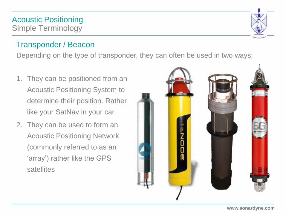
Transponder / Beacon
Depending on the type of transponder, they can often be used in two ways:
1. They can be positioned from an
Acoustic Positioning System to
determine their position. Rather
like your SatNav in your car.
2. They can be used to form an
Acoustic Positioning Network
(commonly referred to as an
‘array’) rather like the GPS
satellites
www.sonardyne.com
Acoustic Positioning Simple Terminology
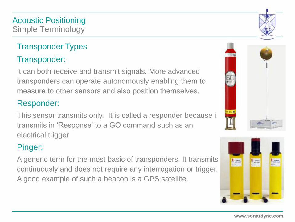
Transponder Types
Transponder:
It can both receive and transmit signals. More advanced
transponders can operate autonomously enabling them to
measure to other sensors and also position themselves.
Responder:
This sensor transmits only. It is called a responder because it
transmits in ‘Response’ to a GO command such as an
electrical trigger
Pinger:
A generic term for the most basic of transponders. It transmits
continuously and does not require any interrogation or trigger.
A good example of such a beacon is a GPS satellite.

www.sonardyne.com
Acoustic Positioning Simple Terminology
Transceivers
Transceivers are typically wired sensors capable of
receiving information from, and transmitting information
to transponders.
1. Basic transceivers can be used much like the
antenna inside your SatNav to receive signals
from transponders
2. Advanced, multi-element transceivers can
determine range and bearing and hence calculate
the relative position of a transponder
3. Transceivers can also be used as modems
www.sonardyne.com
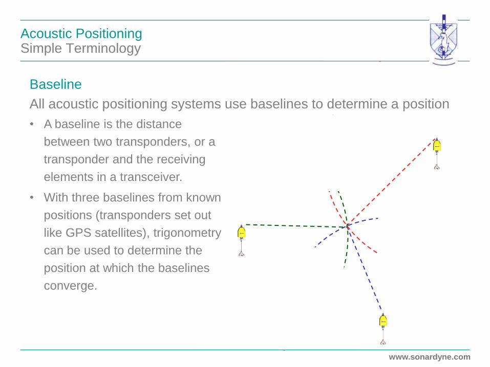
Acoustic Positioning Simple Terminology
• A baseline is the distance
between two transponders, or a
transponder and the receiving
elements in a transceiver.
• With three baselines from known
positions (transponders set out
like GPS satellites), trigonometry
can be used to determine the
position at which the baselines
converge.
Baseline
All acoustic positioning systems use baselines to determine a position

www.sonardyne.com
Acoustic Positioning Hydrofest
1. An Introduction to Acoustic Positioning
• Why, Where and How
• Simple Terminology
• Acoustic Signals
• Acoustic Positioning Methods
2. Long BaseLine (LBL)
3. Ultra Short BaseLine (USBL)
4. Aided Inertial Navigation Systems
5. Choosing a System
www.sonardyne.com

www.sonardyne.com
Acoustic Positioning Baseline Measurement
Acoustic Positioning Systems Measure Time, Not Distance
1. A signal is sent from the transceiver or transponder and an internal clock is
started.
2. The reply signal is received from the target, the clock stops and the total time
for the signal cycle is logged.
3. Add the Speed of Sound along with the TurnAround Time (TAT) and you
have distance
Note: Sound Speed constantly changes so has
to be measured on a regular basis
Turnaround
Time (TAT)

www.sonardyne.com
Acoustic Positioning Tone Signal – Correlation Processing
Tone Signal
good time of
arrival estimation
Analogue is traditional acoustic signal technology
• One transmission per carrier frequency, means limited number
of channels
• Processing affected by high noise
• Range determination can be better than 20cm

www.sonardyne.com
Acoustic Positioning Digital Signal – Correlation Processing
Digital Acoustic Signal Technology
• Unique codes rather like serial numbers, meaning hundreds of channels
• Digital signals are more robust than analogue in high noise
• Range determination can be better than 1cm
Wideband Signal
excellent time of
arrival estimation

www.sonardyne.com
Acoustic Positioning Hydrofest
1. An Introduction to Acoustic Positioning
• Why, Where and How
• Simple Terminology
• Acoustic Signals
• Acoustic Positioning Methods
2. Long BaseLine (LBL)
3. Ultra Short BaseLine (USBL)
4. Aided Inertial Navigation Systems
5. Choosing a System
www.sonardyne.com

www.sonardyne.com
Techniques Subsea Positioning is similar to…

www.sonardyne.com
LBL - Theory of Operation How do we obtain positioning on land?
• GPS Network

www.sonardyne.com
LBL - Theory of Operation Vessel Tracking
100s/1000s of Metres
• Seabed transponder array
at known co-ordinates
• Single element Transceiver
• Ranges are derived and
position calculated
• Up to Centrimetric
accuracy
• Accuracy independent of
water depth

www.sonardyne.com
LBL - Theory of Operation Subsea Vehicle Tracking
Seabed transponder array
can also be used to position
subsea vehicles such as an
ROV
www.sonardyne.com
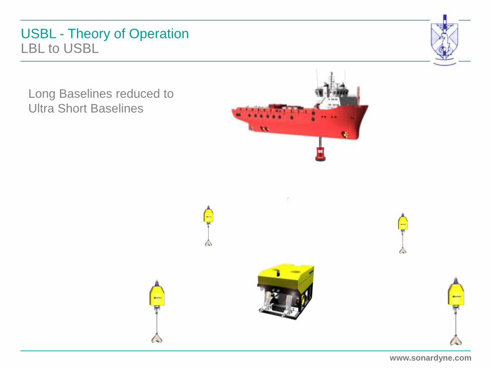
USBL - Theory of Operation LBL to USBL
Long Baselines reduced to
Ultra Short Baselines
www.sonardyne.com
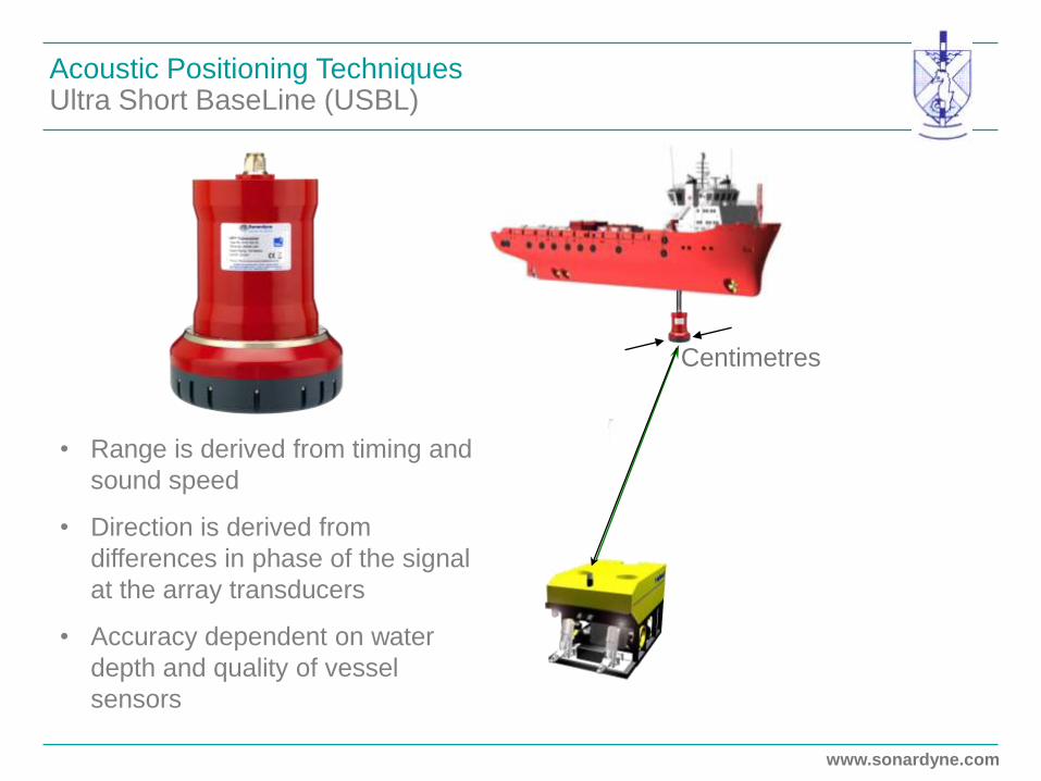
Acoustic Positioning Techniques Ultra Short BaseLine (USBL)
• Range is derived from timing and
sound speed
• Direction is derived from
differences in phase of the signal
at the array transducers
• Accuracy dependent on water
depth and quality of vessel
sensors
Centimetres
www.sonardyne.com
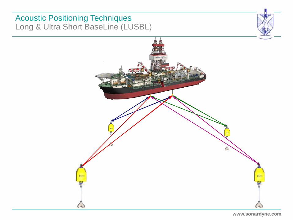
Acoustic Positioning Techniques Long & Ultra Short BaseLine (LUSBL)
www.sonardyne.com
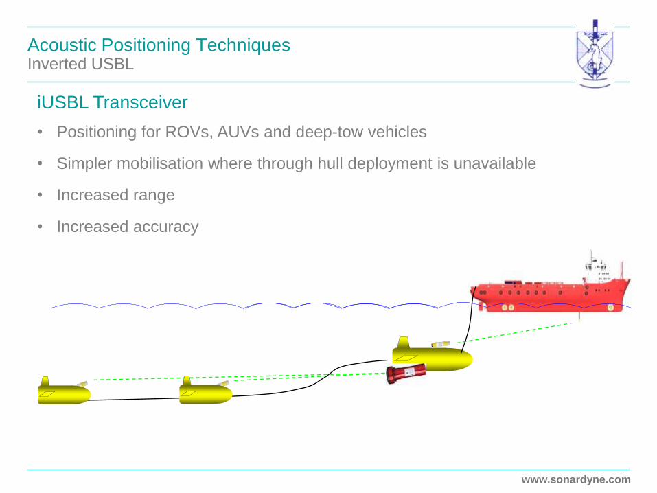
Acoustic Positioning Techniques Inverted USBL
iUSBL Transceiver
• Positioning for ROVs, AUVs and deep-tow vehicles
• Simpler mobilisation where through hull deployment is unavailable
• Increased range
• Increased accuracy

www.sonardyne.com
Acoustic Positioning Hydrofest
1. An Introduction to Acoustic Positioning
2. Long BaseLine (LBL)
• Hardware Setup
• Calibration
• Accuracy and Update rates
3. Ultra Short BaseLine (USBL)
4. Aided Inertial Navigation Systems
5. Choosing a System
www.sonardyne.com
www.sonardyne.com
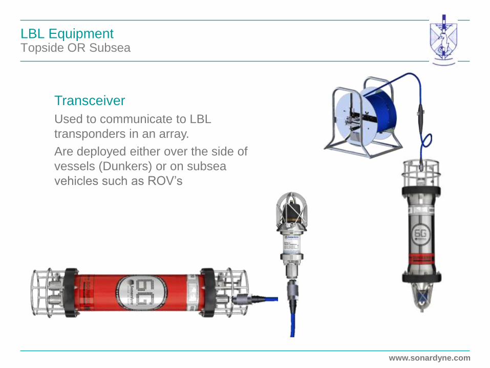
LBL Equipment Topside OR Subsea
Transceiver
Used to communicate to LBL
transponders in an array.
Are deployed either over the side of
vessels (Dunkers) or on subsea
vehicles such as ROV’s

www.sonardyne.com
LBL Equipment Subsea
1. Collect data or configure operational settings
2. Measure acoustic travel time to a second transponder
3. Respond as an array transponder
4. Observe and report two-way travel times to an array of
Compatts
5. Respond to an interrogation from a USBL system
An Intelligent Transponder that can;

www.sonardyne.com
Long BaseLine (LBL) System Overview
Vessel Equipment
ROV Equipment
Seabed
Equipment
+
+
www.sonardyne.com
Acoustic Positioning Hydrofest
1. An Introduction to Acoustic Positioning
2. Long BaseLine (LBL)
• Hardware Setup
• Calibration
• Accuracy and Update rates
3. Ultra Short BaseLine (USBL)
4. Aided Inertial Navigation Systems
5. Choosing a System
www.sonardyne.com

www.sonardyne.com
Acoustic Positioning LBL Calibration
Observations
• Depth
• Baselines Distances
• Trial Positions

www.sonardyne.com
Acoustic Positioning LBL Calibration – Relative Array Positions
Least squares
adjustment to
derive best
estimate of
transponder
positions and
depths
www.sonardyne.com
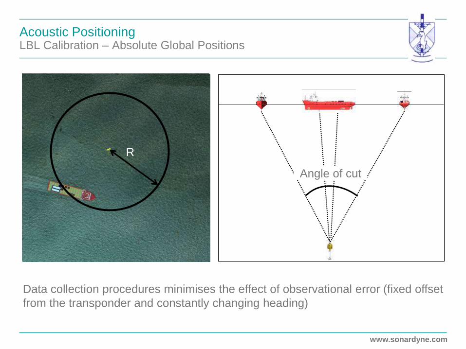
Acoustic Positioning LBL Calibration – Absolute Global Positions
Angle of cut
Data collection procedures minimises the effect of observational error (fixed offset
from the transponder and constantly changing heading)
R
www.sonardyne.com
Acoustic Positioning Hydrofest
1. An Introduction to Acoustic Positioning
2. Long BaseLine (LBL)
• Hardware Setup
• Calibration
• Accuracy and Update rates
3. Ultra Short BaseLine (USBL)
4. Aided Inertial Navigation Systems
5. Choosing a System
www.sonardyne.com
www.sonardyne.com
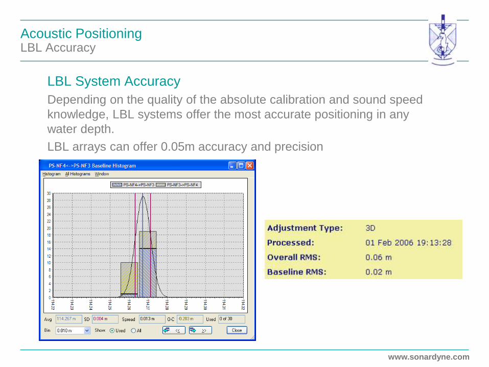
Acoustic Positioning LBL Accuracy
LBL System Accuracy
Depending on the quality of the absolute calibration and sound speed
knowledge, LBL systems offer the most accurate positioning in any
water depth.
LBL arrays can offer 0.05m accuracy and precision

www.sonardyne.com
Acoustic Positioning Update Rate
Update Rates
Acoustic positioning systems vary in their update rate and tend to
provide slower update rates than surface based positioning sensors.
This is due to the fact that acoustic
signals travel at approximately
1,500m/sec through seawater. This
means that for a 1,500m baseline, the
acoustic signal would take 2 seconds
to travel to and from the transponder.

www.sonardyne.com
Acoustic Positioning LBL Update Rate
LBL Systems Update Rate
Using digital signals, the signals themselves can be interleaved allowing
simultaneous transmission of signals from all the array transponders. In the
past, tone signal based transponder replies had to be delayed to avoid any
signal overlap.
700 800 900 1000 1100 1200 1300 1400 1500 16000
0.1
0.2
0.3
0.4
0.5
0.6
0.7
0.8
0.9
1
Same code four orthogonal carriers
Pinger type LBL systems can transmit
acoustic signals once a second
allowing an update rate of once per
second.
Modern LBL systems utilising
transponders can provide update rates
between 1 and 3 seconds depending
on the physical size of the array.

www.sonardyne.com
Acoustic Positioning Hydrofest
1. An Introduction to Acoustic Positioning
2. Long BaseLine (LBL)
3. Ultra Short BaseLine (USBL)
• Hardware Setup
• Calibration
• Accuracy and Update rates
4. Aided Inertial Navigation Systems
5. Choosing a System
www.sonardyne.com

www.sonardyne.com
USBL Equipment Topside
USBL Transceiver
A single unit which contains a minimum of three elements to form the
Ultra Short Baseline
www.sonardyne.com
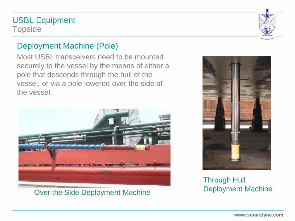
USBL Equipment Topside
Through Hull
Deployment Machine Over the Side Deployment Machine
Deployment Machine (Pole)
Most USBL transceivers need to be mounted
securely to the vessel by the means of either a
pole that descends through the hull of the
vessel, or via a pole lowered over the side of
the vessel.
www.sonardyne.com
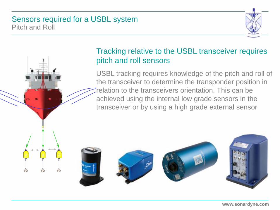
Sensors required for a USBL system Pitch and Roll
Tracking relative to the USBL transceiver requires
pitch and roll sensors
USBL tracking requires knowledge of the pitch and roll of
the transceiver to determine the transponder position in
relation to the transceivers orientation. This can be
achieved using the internal low grade sensors in the
transceiver or by using a high grade external sensor
www.sonardyne.com
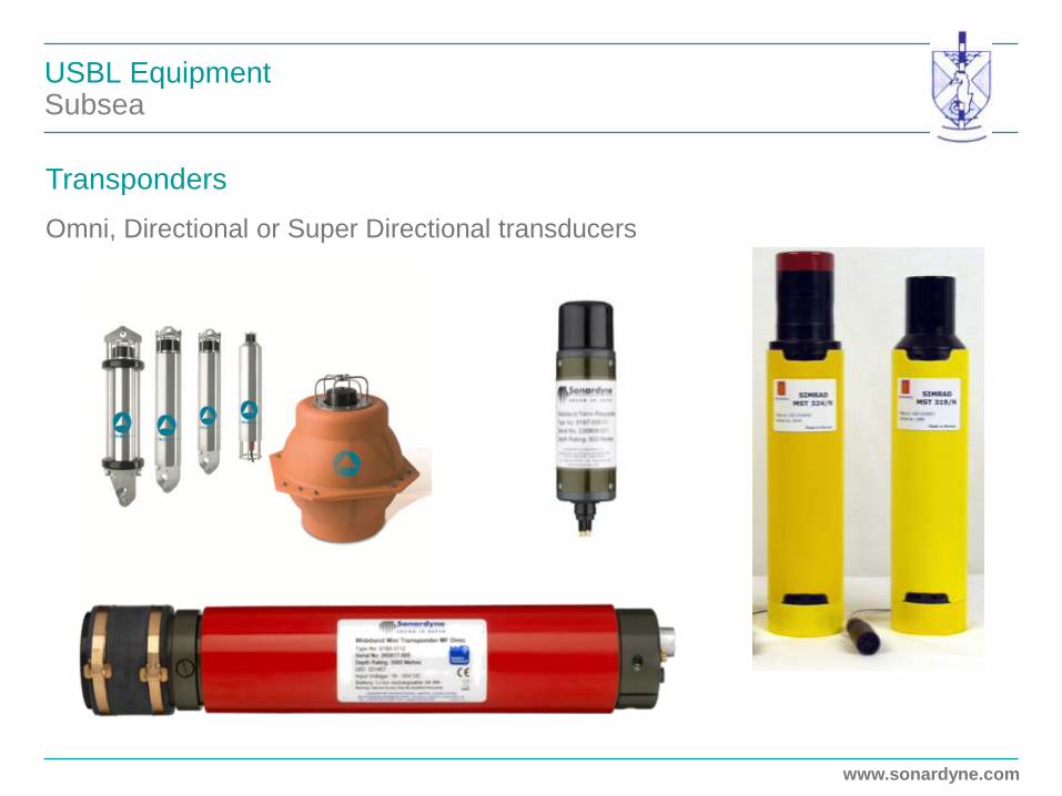
USBL Equipment Subsea
Transponders
Omni, Directional or Super Directional transducers

www.sonardyne.com
Ultra Short BaseLine (USBL) System Overview
Vessel Equipment
Seabed Equipment
+ + +
+ or or

www.sonardyne.com
Sensors required for a USBL system Heading
Tracking relative to the vessel also requires a
heading sensor
To determine the relative position of the transponder in
relation to the vessel, a heading instrument aligning
the transceiver to the ships forward axis is required.
This is achieved using an external gyrocompass or
equivalent
Zoomed In
NORTH

www.sonardyne.com
Sensors required for a USBL system GPS
Tracking with absolute co-ordinates or calibrating requires a position
sensor
To determine the absolute co-ordinates of the transponder, and to calibrate the
interfaced sensors, a position instrument is required. This is achieved by
interfacing a GPS instrument
NORTH
X
Y Lat 57.2897º N
Long 2.3881º W
GPS enables
absolute
positioning
NORTH
Lat 57.2903º N
Long 2.3897º W

www.sonardyne.com
Acoustic Positioning Hydrofest
1. An Introduction to Acoustic Positioning
2. Long BaseLine (LBL)
3. Ultra Short BaseLine (USBL)
• Hardware Setup
• Calibration
• Accuracy and Update rates
4. Aided Inertial Navigation Systems
5. Choosing a System
www.sonardyne.com

www.sonardyne.com
Acoustic Positioning USBL Calibration
USBL Calibration
A USBL system for calibration consists of:
• USBL software
• USBL transceiver
• Vessel Attitude sensors (pitch, roll and heading)
• GPS
• Seabed transponder
A calibration routine is required to ensure
all these sensors are precisely aligned and
offset from each.
The better the calibration (system
alignment), then the more accurate the
system performance will be High precision with no
systematic or gross errors

www.sonardyne.com
Acoustic Positioning CASIUS – Calibration of Attitude Sensors In USBL System
The process starts by
deploying a reference
acoustic transponder on to
the seabed
The vessel then sails in a pre-
determined calibration pattern
over and around the
transponder whilst
simultaneously collecting
DGPS, USBL, and attitude
data
During this process, the data
is logged by the USBL
system.

www.sonardyne.com
Acoustic Positioning CASIUS – Calibration of Attitude Sensors In the USBL System
CASIUS Calibration
Data Collection
N
S
E W

www.sonardyne.com
Acoustic Positioning Hydrofest
1. An Introduction to Acoustic Positioning
2. Long BaseLine (LBL)
3. Ultra Short BaseLine (USBL)
• Hardware Setup
• Calibration
• Accuracy and Update rates
4. Aided Inertial Navigation Systems
5. Choosing a System
www.sonardyne.com

www.sonardyne.com
Acoustic Positioning USBL Accuracy
USBL System Accuracy
USBL transducers offer positioning precision that deteriorates the further the
transponder is from the array.
System accuracy is dependent on the quality and calibration of all the integrated
sensors.
USBL system accuracy is normally quoted in terms of a percentage of slant range.
Survey grade USBL systems can offer up to 0.1% of slant range (1m in 1,000m)
A CASIUS in 4,870m Water Depth – Bay of Biscay
Statistic CASIUS Results
1 DRMS (63.2%) of
observations
7.2m (0.12% of slant range)
+ + +

www.sonardyne.com
Acoustic Positioning USBL Update Rate
USBL System Update Rate
USBL systems are also dependent on the speed of sound.
Responders do not require the interrogation signal so the update rate will be half
that of a transponder.
Techniques such as ‘Ping Stacking’ and the use
of digital signals, modern USBL systems can
achieve updates rates of 1 second in any water
depth and with any number of simultaneous
received transponders

www.sonardyne.com
Acoustic Positioning Hydrofest
1. An Introduction to Acoustic Positioning
2. Long BaseLine (LBL)
3. Ultra Short BaseLine (USBL)
4. Aided Inertial Navigation Systems
5. Choosing a System
www.sonardyne.com

www.sonardyne.com
Inertial Navigation Systems
It’s Not New
• Commercial, Military, Space Aircraft
• Submarines, AUV, ROV
• Tanks – Payload Stabilisation
• Mobile Remote Sensing Survey
• Airborne Survey and Inspection

www.sonardyne.com
Track Performance Improvement Through Aided INS
What it Does
••••••• Actual vehicle track
••••••• USBL generated track
••••••• INS dead reckoning track
••••••• AINS track
Simulated data
N
E
www.sonardyne.com
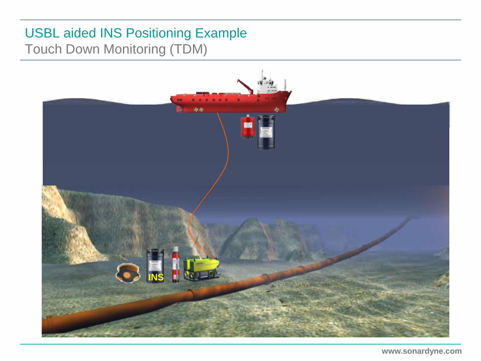
USBL aided INS Positioning Example
Touch Down Monitoring (TDM)
INS

www.sonardyne.com
ROV INS - SPRINT
Sparse LBL aided INS Example

www.sonardyne.com
USBL aided INS Positioning Example
ROV Transiting Along Pipe to Touch Down Point
• USBL + DVL +
Depth
• INS filling in the
gaps

www.sonardyne.com
USBL aided INS Positioning Example
ROV relocates to next Field Joint
• ROV static on a
field joint
• USBL (5s) +
DVL + Depth
aiding
• Range 400m
• Depth 100m

www.sonardyne.com
Acoustic Positioning Hydrofest
1. An Introduction to Acoustic Positioning
2. Long BaseLine (LBL)
3. Ultra Short BaseLine (USBL)
4. Aided Inertial Navigation Systems
5. Choosing a System
www.sonardyne.com

www.sonardyne.com
Acoustic Positioning Choosing a System
The accuracy requirements of the task to be carried out will determine
the Acoustic System that should be used.
For example;
Pipelay Operations
Often this would
require high update
rates over high
accuracy. Therefore a
USBL system would
be considered.
www.sonardyne.com
Acoustic Positioning Choosing a System
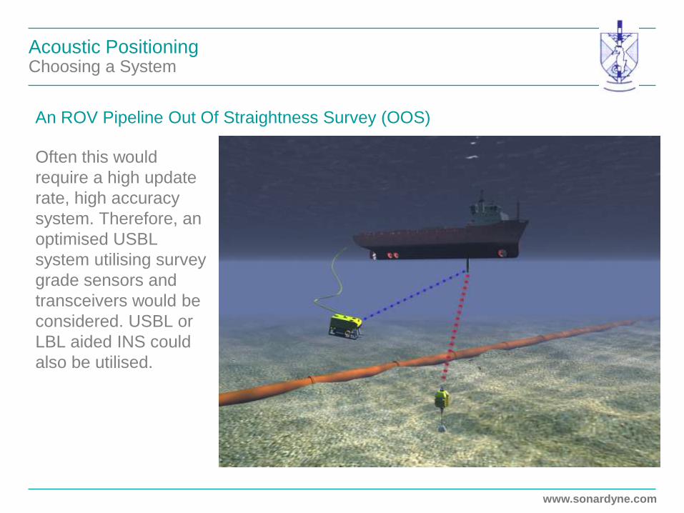
Often this would
require a high update
rate, high accuracy
system. Therefore, an
optimised USBL
system utilising survey
grade sensors and
transceivers would be
considered. USBL or
LBL aided INS could
also be utilised.
An ROV Pipeline Out Of Straightness Survey (OOS)

www.sonardyne.com
Acoustic Positioning Choosing a System
A Deepwater Structure Installation
This operation would require increased accuracy over update rate.
Therefore, LBL would be considered.

www.sonardyne.com
Head Office
Sonardyne International Limited T. +44 (0) 1252 872288
Blackbushe Business Park F. +44 (0) 1252 876100
Yateley, Hampshire, GU46 6GD E. [email protected]
United Kingdom www.sonardyne.com


