CSI
AL-6XN® AlloyTechnical Data & Product Catalog
Bringing Innovation to Process Systems
General Properties . . . . . . . . . . . . . . . . . . . . . . . . . . . . . . . . . . . . . . . . . . . . . . . . . . . . . . . . . . . . . . . . . . . . . . . .1
Specifications . . . . . . . . . . . . . . . . . . . . . . . . . . . . . . . . . . . . . . . . . . . . . . . . . . . . . . . . . . . . . . . . . . . . . . . . . .1
Physical Properties . . . . . . . . . . . . . . . . . . . . . . . . . . . . . . . . . . . . . . . . . . . . . . . . . . . . . . . . . . . . . . . . . . . . . . . .2
Surface Finish Designator . . . . . . . . . . . . . . . . . . . . . . . . . . . . . . . . . . . . . . . . . . . . . . . . . . . . . . . . . . . . . . . . . . .3
Designator Location . . . . . . . . . . . . . . . . . . . . . . . . . . . . . . . . . . . . . . . . . . . . . . . . . . . . . . . . . . . . . . . . . . . . .3
Surface Finish Options. . . . . . . . . . . . . . . . . . . . . . . . . . . . . . . . . . . . . . . . . . . . . . . . . . . . . . . . . . . . . . . . . . . .3
CSI Quality Standards . . . . . . . . . . . . . . . . . . . . . . . . . . . . . . . . . . . . . . . . . . . . . . . . . . . . . . . . . . . . . . . . . . . . .4
Mechanically Polished “P7 and 7” Designations. . . . . . . . . . . . . . . . . . . . . . . . . . . . . . . . . . . . . . . . . . . . . . . . . .4
Electropolished “P25” Designations . . . . . . . . . . . . . . . . . . . . . . . . . . . . . . . . . . . . . . . . . . . . . . . . . . . . . . . . . .5
Product Catalog . . . . . . . . . . . . . . . . . . . . . . . . . . . . . . . . . . . . . . . . . . . . . . . . . . . . . . . . . . . . . . . . . . . . . . . . . .6
AL-6XN Alloy Tubing . . . . . . . . . . . . . . . . . . . . . . . . . . . . . . . . . . . . . . . . . . . . . . . . . . . . . . . . . . . . . . . . . . . . .6
Weld Insert Rings. . . . . . . . . . . . . . . . . . . . . . . . . . . . . . . . . . . . . . . . . . . . . . . . . . . . . . . . . . . . . . . . . . . . . . . .6
Standard Items . . . . . . . . . . . . . . . . . . . . . . . . . . . . . . . . . . . . . . . . . . . . . . . . . . . . . . . . . . . . . . . . . . . . . . . . .7
Ferrules . . . . . . . . . . . . . . . . . . . . . . . . . . . . . . . . . . . . . . . . . . . . . . . . . . . . . . . . . . . . . . . . . . . . . . . . . . .7
Elbows . . . . . . . . . . . . . . . . . . . . . . . . . . . . . . . . . . . . . . . . . . . . . . . . . . . . . . . . . . . . . . . . . . . . . . . . . . . .9
Tees . . . . . . . . . . . . . . . . . . . . . . . . . . . . . . . . . . . . . . . . . . . . . . . . . . . . . . . . . . . . . . . . . . . . . . . . . . . . .11
Instrument Tees . . . . . . . . . . . . . . . . . . . . . . . . . . . . . . . . . . . . . . . . . . . . . . . . . . . . . . . . . . . . . . . . . . . . .14
True and Lateral Ys . . . . . . . . . . . . . . . . . . . . . . . . . . . . . . . . . . . . . . . . . . . . . . . . . . . . . . . . . . . . . . . . . .15
Reducers . . . . . . . . . . . . . . . . . . . . . . . . . . . . . . . . . . . . . . . . . . . . . . . . . . . . . . . . . . . . . . . . . . . . . . . . .16
Sanitary Pipe Adapters and Caps . . . . . . . . . . . . . . . . . . . . . . . . . . . . . . . . . . . . . . . . . . . . . . . . . . . . . . . .20
Clamps . . . . . . . . . . . . . . . . . . . . . . . . . . . . . . . . . . . . . . . . . . . . . . . . . . . . . . . . . . . . . . . . . . . . . . . . . .21
Applications and Additional Options. . . . . . . . . . . . . . . . . . . . . . . . . . . . . . . . . . . . . . . . . . . . . . . . . . . . . . . . .22
Standard Transfer Panel Configurations . . . . . . . . . . . . . . . . . . . . . . . . . . . . . . . . . . . . . . . . . . . . . . . . . . . . . . .23
Jacketed Tubing . . . . . . . . . . . . . . . . . . . . . . . . . . . . . . . . . . . . . . . . . . . . . . . . . . . . . . . . . . . . . . . . . . . . . . .24
Welding AL-6XN Alloy . . . . . . . . . . . . . . . . . . . . . . . . . . . . . . . . . . . . . . . . . . . . . . . . . . . . . . . . . . . . . . . . . . . .25
General Welding Recommendations . . . . . . . . . . . . . . . . . . . . . . . . . . . . . . . . . . . . . . . . . . . . . . . . . . . . . . . . .25
Special Welding Requirements . . . . . . . . . . . . . . . . . . . . . . . . . . . . . . . . . . . . . . . . . . . . . . . . . . . . . . . . . . . . .27
Autogenous Welding . . . . . . . . . . . . . . . . . . . . . . . . . . . . . . . . . . . . . . . . . . . . . . . . . . . . . . . . . . . . . . . . . . . .27
Weld Appearance . . . . . . . . . . . . . . . . . . . . . . . . . . . . . . . . . . . . . . . . . . . . . . . . . . . . . . . . . . . . . . . . . . . . . .28
Weld Test and Analysis. . . . . . . . . . . . . . . . . . . . . . . . . . . . . . . . . . . . . . . . . . . . . . . . . . . . . . . . . . . . . . . . . . .28
AL-6XN® Alloy Technical Data & Product Catalog
Table of Contents
www.al6xn.com 1
It is now possible to extend the life of system com-ponents that may experience problems with chlo-ride induced corrosion by using AL-6XN® (UNS N08367) alloy sanitary tubing and fittings supplied by CSI. AL-6XN alloy is a “superaustenitic,” low carbon stainless steel containing chromium, nickel, molybdenum, and nitrogen.
AL-6XN� DOOR\� LV� PHWDOOXUJLFDOO\� VWDEOH� WR� ����Ý)�����Ý&�� DQG� KDV� QR� SKDVH� WUDQVIRUPDWLRQ� HYHQ� after extensive deformation. Long term exposure in the WHPSHUDWXUH�UDQJH�RI�����²����Ý)�����²����Ý&��may result in the formation of a secondary phase (chi or sigma phase) along the grain boundaries. These secondary phases may adversely affect corrosion re-sistance and should be avoided.
Nitrogen is added to the alloy to minimize secondary phase formation, improve its corrosion resistance, in-crease its strength over a broad temperature range, and retain the superior formability of austenitic
stainless steel. AL-6XN alloy has a face-centered cu-bic crystal structure similar to other austenitic stain-less steels. The AL-6XN alloy is non-magnetic, and its magnetic permeability remains low even after se-vere cold forming.
General
ProductSpecifications
ASME ASTM
Plate, Sheet & StripSA 240
SB-688
A 240
B 688
Rod, Bar & Wire SB-691 B 691
Welded Pipe SB-675 B 675
Heat Exchanger Tubing SA-249 A 249
Sanitary Tubing A 270
Welded Tube (General Applications) SB-676B 676
A 269
Seamless Pipe & Tube SB-690 B 690
Billets and Bars for Reforging B 472
Forged Pipe Flanges, Fittings & Valves SB-462 B 462
Wrought Nickel Alloy Welded Fittings SB-366 B 366
Nickel Alloy Forgings SB-564 B 564
Pipe Welded w/ Filler SB-804 B 804
Castings (CN-3MN, UNS J94651) SA-351A 743
A 744
MZ[e^�BB3�:LF>���:LMF�Li^\bÛ\Zmbhgl�!NGL�G)1,/0"
September 2012
Properties
Element Typical AllowableCarbon 0.02 0.03 maximum
Manganese 0.40 2.00 maximum
Phosphorus 0.020 0.040 maximum
Sulfur 0.001 0.030 maximum
Silicon 0.40 1.00 maximum
Chromium 20.5 20.00 / 22.00
Nickel 24.00 23.50 / 25.50
Molybdenum 6.20 6.00 / 7.00
Nitrogen 0.22 0.18 / 0.25
Copper 0.2 0.75
Iron Balance Balance
Table I: Chemical Composition of AL-6XN® Alloy
Disclaimer: Always consult current standards.
SpecificationsThe American Society of Mechanical Engineers (ASME) and the American Society for Testing and Materials (ASTM) specifications for the wide range of AL-6XN alloy forms are listed in table II. AL-6XN alloy is approved for ASME Boiler and Pres-sure Vessel Code construction (Section VIII Div. 1) as Code Case 1997.
Source: ATI Allegheny Ludlum

Physical
AlloyElastic Modulus Ma^kfZe�<hg]n\mbobmr�Zm�+*+ì? >qiZglbhg�<h^_Û\b^gm�_khf�00�mh�+*+ì?
ilb�q�*)6 GPa ;mn(ak���_m���ì? P(!f�D" *)-6(ì? *)-6(ì<Type 316L 29.0 200 9.2 16.0 8.5 15.3
AL-6XN® +1', 195 0'. *,') 0'2 *-'+Alloy 904L 28.3 195 7.6 13.2 8.3 15.0Alloy 625 29.7 205 6.2 10.7 7.1 12.8Nickel 200 30.0 207 38.8 67.1 7.4 13.4
C-276 29.8 205 6.4 9.9 6.2 11.2
C-22® 29.9 206 6.4 11.1 6.9 12.4Titanium 15.0 103 9.5 16.4 5.0 9.1
Table III: Comparison of Physical Properties
Property Value Units
Density0.291 lb/in3
8.06 g/cm3
Modulus of Elasticity28.3 x 106 psi
195 GPa
Melting Range2410 to 2550 Ý)1320 to 1400 Ý&
Thermal Conductivity���WR����Ý)���WR����Ý&
7.5 Btu/hr���ft���Ý)14.1 :��P�.�
Coefficient of Expansion���WR����Ý)���WR����Ý&
7.9 10-6�Ý)14.2 10-6�Ý&
Specific Heat capacity0.11 Btu/lb���Ý)500 J/kg���.
Electrical Resistivity535 Ohm ��circ mil/ft0.89 �P
Scaling temperature1885 Ý)1030 Ý&
Table IV: Physical Properties of AL-6XN® Alloy at Room Temperature
The physical properties of AL-6XN® alloy are similar to those of other austenitic stainless steels (table III). The elastic modulus values of AL-6XN alloy are lower than those for Type 316L and Alloy 625. However, these moduli are high in comparison to such non-ferrous alloys
as titanium. The thermal conductivity and coeffi-cient of expansion values are lower than those for Type 316L but are higher than Alloy 625. Physical properties of AL-6XN alloy at room temperature are presented in table IV.
Bringing Innovation to Process Systems2
September 2012
Properties
Sources: ATI Allegheny Ludlum and Haynes International
Source: ATI
Surface Finish
Finish Code
Product Contact Max Ra*
Product Contact Surface Finish Treatment (ID)
Non-Product Contact Max Ra*
Non-Product Contact Surface Finish Treat-
ment (OD)
P7 32 µ-inch 0.8 µm Mechanical Polish 32 µ-inch 0.8 µm Mechanical Polish7 32 µ-inch 0.8 µm Mechanical Polish 32 µ-inch 0.8 µm Mechanical Polish
P25 25 µ-inch 0.6 µm Electropolished 32 µ-inch 0.8 µm Mechanical Polish
Table V: Surface Finish Designator Code
*A 32 µ-inch (0.8 µm) surface finish is comparable to a 150 grit or better and considered to be equivalent to a No. 4 finish as defined in 3-A Sanitary Standards. 32 µ-inch Max Ra is an approximate value and is not guaranteed. Surface finish roughness shall be physically examined for “P25” using a profilometer calibrated to standards traceable to NIST. Surface finish roughness shall NOT be subject to physi-cal examination for “P7” or “7”.
The finish designator is indicated in the CSI part number as a suffix. The suffix will define the fin-ishing requirements for that process component. Each part number can have several finish desig-nators applied to it. Figure 1 is an example of a
part number with a specified finish designator of “7.” Each finish designator in table V indicates the roughness average (Ra) specifications for the product and non-product contact surfaces.
Mechanically Polished Tubing & Fittings !I0���0"
The outside of the tube shall be mechanically pol-ished to a surface finish comparable to 0.8 µm or better and considered to be equivalent to a No. 4 finish as defined in 3-A Sanitary Standards.
The interior surfaces shall be drawn or mechani-cally polished to a 32 µ-inch Ra maximum finish for sizes 1/2” through 4” diameter. No interior sur-face finish reading above 32 µ-inch Ra is accept-able unless dimensionally defined in the table V.
Electropolished Tubing & Fittings !I+."
The outside of tubing and fittings shall be mechani-cally polished to a 32 µ-inch Ra maximum finish.
The interior surfaces shall be mechanically pol-ished, or as drawn, to a 25 µ-inch Ra maximum finish for sizes 1/2” through 4” diameter. The elec-tropolishing process may increase the Ra values post electropolishing and have areas of preferential etching (e.g., frosting or shadowing). Final Ra val-ues for electropolished tubing and fittings shall not be used as criteria of acceptance for this product.
Designator
Product Group
;,* &�,Q+'. - AL6XN�&�0Figure 1
Nominal Size
Reduced Size
Material
Finish Designator Code
Surface Finish Options
Designator Location
ZZZ�DO�[Q�FRP����������������� 3
September 2012
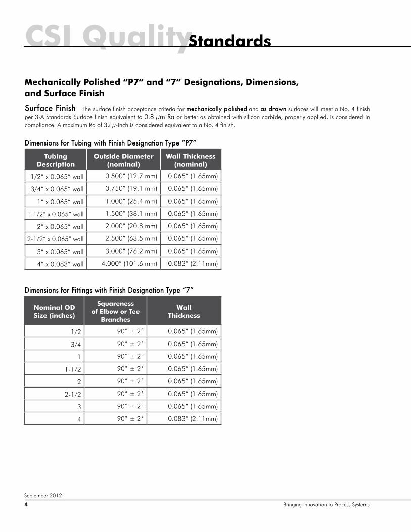
StandardsCSI QualityMechanically Polished “P7” and “7” Designations, Dimensions, and Surface Finish
Tubing Description
Outside Diameter (nominal)
Wall Thickness (nominal)
1/2” x 0.065” wall 0.500” (12.7 mm) 0.065” (1.65mm)
3/4” x 0.065” wall 0.750” (19.1 mm) 0.065” (1.65mm)
1” x 0.065” wall 1.000” (25.4 mm) 0.065” (1.65mm)
1-1/2” x 0.065” wall 1.500” (38.1 mm) 0.065” (1.65mm)
2” x 0.065” wall 2.000” (20.8 mm) 0.065” (1.65mm)
2-1/2” x 0.065” wall 2.500” (63.5 mm) 0.065” (1.65mm)
3” x 0.065” wall 3.000” (76.2 mm) 0.065” (1.65mm)
4” x 0.083” wall 4.000” (101.6 mm) 0.083” (2.11mm)
Dimensions for Tubing with Finish Designation Type “P7”
Nominal OD Size (inches)
Squareness of Elbow or Tee
Branches
Wall Thickness
1/2 90˚ ± 2˚ 0.065” (1.65mm)
3/4 90˚ ± 2˚ 0.065” (1.65mm)
1 90˚ ± 2˚ 0.065” (1.65mm)
1-1/2 90˚ ± 2˚ 0.065” (1.65mm)
2 90˚ ± 2˚ 0.065” (1.65mm)
2-1/2 90˚ ± 2˚ 0.065” (1.65mm)
3 90˚ ± 2˚ 0.065” (1.65mm)
4 90˚ ± 2˚ 0.083” (2.11mm)
Dimensions for Fittings with Finish Designation Type “7”
Surface Finish The surface finish acceptance criteria for mechanically polished and as drawn surfaces will meet a No. 4 finish per 3-A Standards. Surface finish equivalent to 0.8 µm Ra or better as obtained with silicon carbide, properly applied, is considered in compliance. A maximum Ra of 32 µ-inch is considered equivalent to a No. 4 finish.
Bringing Innovation to Process Systems4
September 2012
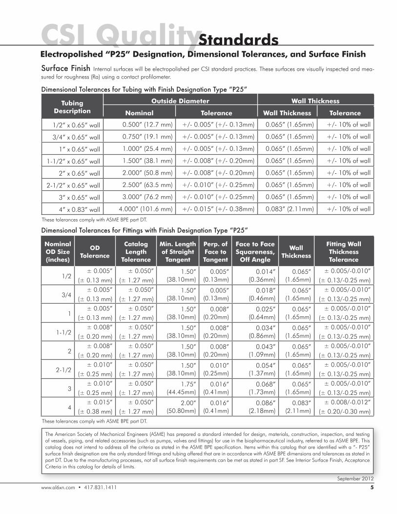
StandardsCSI QualityElectropolished “P25” Designation, Dimensional Tolerances, and Surface Finish
Surface Finish Internal surfaces will be electropolished per CSI standard practices. These surfaces are visually inspected and mea-sured for roughness (Ra) using a contact profilometer.
The American Society of Mechanical Engineers (ASME) has prepared a standard intended for design, materials, construction, inspection, and testing of vessels, piping, and related accessories (such as pumps, valves and fittings) for use in the biopharmaceutical industry, referred to as ASME BPE. This catalog does not intend to address all the criteria as stated in the ASME BPE specification. Items within this catalog that are identified with a “- P25” surface finish designation are the only standard fittings and tubing offered that are in accordance with ASME BPE dimensions and tolerances as stated in part DT. Due to the manufacturing processes, not all surface finish requirements can be met as stated in part SF. See Interior Surface Finish, Acceptance Criteria in this catalog for details of limits.
Tubing
Description
Outside Diameter Wall Thickness
Nominal Tolerance Wall Thickness Tolerance
1/2” x 0.65” wall 0.500” (12.7 mm) +/- 0.005” (+/- 0.13mm) 0.065” (1.65mm) +/- 10% of wall
3/4” x 0.65” wall 0.750” (19.1 mm) +/- 0.005” (+/- 0.13mm) 0.065” (1.65mm) +/- 10% of wall
1” x 0.65” wall 1.000” (25.4 mm) +/- 0.005” (+/- 0.13mm) 0.065” (1.65mm) +/- 10% of wall
1-1/2” x 0.65” wall 1.500” (38.1 mm) +/- 0.008” (+/- 0.20mm) 0.065” (1.65mm) +/- 10% of wall
2” x 0.65” wall 2.000” (50.8 mm) +/- 0.008” (+/- 0.20mm) 0.065” (1.65mm) +/- 10% of wall
2-1/2” x 0.65” wall 2.500” (63.5 mm) +/- 0.010” (+/- 0.25mm) 0.065” (1.65mm) +/- 10% of wall
3” x 0.65” wall 3.000” (76.2 mm) +/- 0.010” (+/- 0.25mm) 0.065” (1.65mm) +/- 10% of wall
4” x 0.83” wall 4.000” (101.6 mm) +/- 0.015” (+/- 0.38mm) 0.083” (2.11mm) +/- 10% of wall
Dimensional Tolerances for Tubing with Finish Designation Type “P25”
These tolerances comply with ASME BPE part DT.
Nominal
OD Size
(inches)
OD
Tolerance
Catalog
Length
Tolerance
Min. Length
of Straight
Tangent
Perp. of
Face to
Tangent
Face to Face
Squareness,
Off Angle
Wall
Thickness
Fitting Wall
Thickness
Tolerance
1/2± 0.005”
(± 0.13 mm)
± 0.050”
(± 1.27 mm)1.50”
(38.10mm)0.005”
(0.13mm)0.014”
(0.36mm)0.065”
(1.65mm)± 0.005/-0.010”
(± 0.13/-0.25 mm)
3/4± 0.005”
(± 0.13 mm)
± 0.050”
(± 1.27 mm)1.50”
(38.10mm)0.005”
(0.13mm)0.018”
(0.46mm)0.065”
(1.65mm)± 0.005/-0.010”
(± 0.13/-0.25 mm)
1± 0.005”
(± 0.13 mm)
± 0.050”
(± 1.27 mm)1.50”
(38.10mm)0.008”
(0.20mm)0.025”
(0.64mm)0.065”
(1.65mm)± 0.005/-0.010”
(± 0.13/-0.25 mm)
1-1/2± 0.008”
(± 0.20 mm)
± 0.050”
(± 1.27 mm)1.50”
(38.10mm)0.008”
(0.20mm)0.034”
(0.86mm)0.065”
(1.65mm)± 0.005/-0.010”
(± 0.13/-0.25 mm)
2± 0.008”
(± 0.20 mm)
± 0.050”
(± 1.27 mm)1.50”
(38.10mm)0.008”
(0.20mm)0.043”
(1.09mm)0.065”
(1.65mm)± 0.005/-0.010”
(± 0.13/-0.25 mm)
2-1/2± 0.010”
(± 0.25 mm)
± 0.050”
(± 1.27 mm)1.50”
(38.10mm)0.010”
(0.25mm)0.054”
(1.37mm)0.065”
(1.65mm)± 0.005/-0.010”
(± 0.13/-0.25 mm)
3± 0.010”
(± 0.25 mm)
± 0.050”
(± 1.27 mm)1.75”
(44.45mm)0.016”
(0.41mm)0.068”
(1.73mm)0.065”
(1.65mm)± 0.005/-0.010”
(± 0.13/-0.25 mm)
4± 0.015”
(± 0.38 mm)
± 0.050”
(± 1.27 mm)2.00”
(50.80mm)0.016”
(0.41mm)0.086”
(2.18mm)0.083”
(2.11mm)± 0.008/-0.012”
(± 0.20/-0.30 mm)
Dimensional Tolerances for Fittings with Finish Designation Type “P25”
These tolerances comply with ASME BPE part DT.
www.al6xn.com • 417.831.1411 5
September 2012
Product Catalog
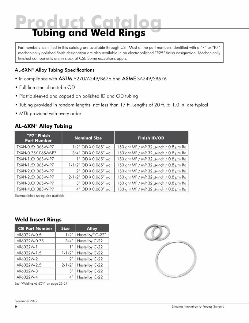
AL-6XN®�:eehr�Mn[bg`�Li^\bÛ\Zmbhgl
��,Q�FRPSOLDQFH�ZLWK�ASTM A270/A249/B676 and ASME SA249/SB676
��)XOO�OLQH�VWHQFLO�RQ�WXEH�2'
��3ODVWLF�VOHHYHG�DQG�FDSSHG�RQ�SROLVKHG�,'�DQG�2'�WXELQJ
��7XELQJ�SURYLGHG�LQ�UDQGRP�OHQJWKV��QRW�OHVV�WKDQ����IW��/HQJWKV�RI����IW��± 1.0 in. are typical
��075�SURYLGHG�ZLWK�HYHU\�RUGHU
Weld Insert Rings
CSI Part Number Size Alloy
AR6022W-0.5 1/2” Hastelloy® C-22®
AR6022W-0.75 3/4” Hastelloy C-22AR6022W-1 1” Hastelloy C-22AR6022W-1.5 1-1/2” Hastelloy C-22AR6022W-2 2” Hastelloy C-22AR6022W-2.5 2-1/2” Hastelloy C-22AR6022W-3 3” Hastelloy C-22AR6022W-4 4” Hastelloy C-22
Part numbers identified in this catalog are available through CSI. Most of the part numbers identified with a “7” or “P7” mechanically polished finish designation are also available in an electropolished “P25” finish designation. Mechanically finished components are in stock at CSI. Some exceptions apply.
AL-6XN® Alloy Tubing
“P7” Finish Part Number Nominal Size Finish ID/OD
T6XN-0.5X.065-W-P7 1/2” OD X 0.065” wall 150 grit MP / MP 32 µ-inch / 0.8 µm RaT6XN-0.75X.065-W-P7 3/4” OD X 0.065” wall 150 grit MP / MP 32 µ-inch / 0.8 µm RaT6XN-1.0X.065-W-P7 1” OD X 0.065” wall 150 grit MP / MP 32 µ-inch / 0.8 µm RaT6XN-1.5X.065-W-P7 1-1/2” OD X 0.065” wall 150 grit MP / MP 32 µ-inch / 0.8 µm RaT6XN-2.0X.065-W-P7 2” OD X 0.065” wall 150 grit MP / MP 32 µ-inch / 0.8 µm RaT6XN-2.5X.065-W-P7 2-1/2” OD X 0.065” wall 150 grit MP / MP 32 µ-inch / 0.8 µm RaT6XN-3.0X.065-W-P7 3” OD X 0.065” wall 150 grit MP / MP 32 µ-inch / 0.8 µm RaT6XN-4.0X.083-W-P7 4” OD X 0.083” wall 150 grit MP / MP 32 µ-inch / 0.8 µm Ra
Tubing and Weld Rings
Bringing Innovation to Process Systems6
September 2012
Electropolished tubing also available
See “Welding AL-6XN” on page 25-27
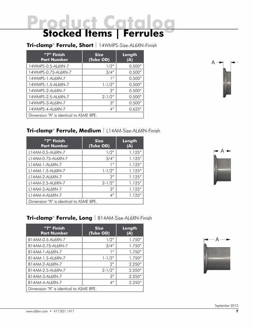
Product CatalogTri-clamp® Ferrule, Short | 14WMPS-Size-AL6XN-Finish
Tri-clamp® Ferrule, Medium | L14AM-Size-AL6XN-Finish
Tri-clamp® Ferrule, Long | B14AM-Size-AL6XN-Finish
“7” Finish Part Number
Size (Tube OD)
Length (A)
B14AM-0.5-AL6XN-7 1/2” 1.750”B14AM-0.75-AL6XN-7 3/4” 1.750”B14AM-1-AL6XN-7 1” 1.750”B14AM-1.5-AL6XN-7 1-1/2” 1.750”B14AM-2-AL6XN-7 2” 2.250”B14AM-2.5-AL6XN-7 2-1/2” 2.250”B14AM-3-AL6XN-7 3” 2.250”B14AM-4-AL6XN-7 4” 2.250”Dimension “A” is identical to ASME BPE.
“7” Finish Part Number
Size (Tube OD)
Length (A)
14WMPS-0.5-AL6XN-7 1/2” 0.500”14WMPS-0.75-AL6XN-7 3/4” 0.500”14WMPS-1-AL6XN-7 1” 0.500”14WMPS-1.5-AL6XN-7 1-1/2” 0.500”14WMPS-2-AL6XN-7 2” 0.500”14WMPS-2.5-AL6XN-7 2-1/2” 0.500”14WMPS-3-AL6XN-7 3” 0.500”14WMPS-4-AL6XN-7 4” 0.625”Dimension “A” is identical to ASME BPE.
“7” Finish Part Number
Size (Tube OD)
Length (A)
L14AM-0.5-AL6XN-7 1/2” 1.125”L14AM-0.75-AL6XN-7 3/4” 1.125”L14AM-1-AL6XN-7 1” 1.125”L14AM-1.5-AL6XN-7 1-1/2” 1.125”L14AM-2-AL6XN-7 2” 1.125”L14AM-2.5-AL6XN-7 2-1/2” 1.125”L14AM-3-AL6XN-7 3” 1.125”L14AM-4-AL6XN-7 4” 1.125”Dimension “A” is identical to ASME BPE.
Stocked Items | Ferrules
ZZZ�DO�[Q�FRP����������������� 7
September 2012
Product Catalog
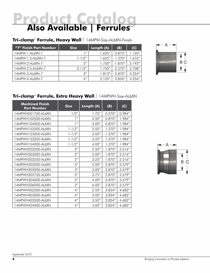
Tri-clamp® Ferrule, Extra Heavy Wall | 14MPWH-Size-AL6XN
Machined Finish Part Number Size Length (A) (B) (C)
14MPWH051750-AL6XN 1/2” 1.75” 0.370” 0.984”14MPWH102500-AL6XN 1” 2.50” 0.870” 1.984”14MPWH104000-AL6XN 1” 4.00” 0.870” 1.984”14MPWH152500-AL6XN 1-1/2” 2.50” 1.370” 1.984”14MPWH153000-AL6XN 1-1/2” 3.00” 1.370” 1.984”14MPWH153250-AL6XN 1-1/2” 3.25” 1.370” 1.984”14MPWH154000-AL6XN 1-1/2” 4.00” 1.370” 1.984”14MPWH202500-AL6XN 2” 2.50” 1.870” 2.516”14MPWH203000-AL6XN 2” 3.00” 1.870” 2.516”14MPWH203250-AL6XN 2” 3.25” 1.870” 2.516”14MPWH302000-AL6XN 3” 2.00” 2.870” 3.579”14MPWH303000-AL6XN 3” 3.00” 2.870” 3.579”14MPWH303750-AL6XN 3” 3.75” 2.870” 3.579”14MPWH304000-AL6XN 3” 4.00” 2.870” 3.579”14MPWH306000-AL6XN 3” 6.00” 2.870” 3.579”14MPWH402500-AL6XN 4” 2.50” 3.834” 4.682”14MPWH403000-AL6XN 4” 3.00” 3.834” 4.682”14MPWH403500-AL6XN 4” 3.50” 3.834” 4.682”14MPWH404000-AL6XN 4” 4.00” 3.834” 4.682”
Tri-clamp® Ferrule, Heavy Wall | 14MPW-Size-AL6XN-Finish
“7” Finish Part Number Size Length (A) (B) (C)
14MPW-1-AL6XN-7 1” 1.625” 0.870” 1.160”14MPW-1.5-AL6XN-7 1-1/2” 1.625” 1.370” 1.676”14MPW-2-AL6XN-7 2” 1.750” 1.870” 2.192”14MPW-2.5-AL6XN-7 2-1/2” 1.750” 2.370” 2.708”14MPW-3-AL6XN-7 3” 1.813” 2.870” 3.224”14MPW-4-AL6XN-7 4” 2.125” 3.834” 4.256”
Also Available | Ferrules
Bringing Innovation to Process Systems8
September 2012

���:HOG�(OO | B2S-Size-AL6XN-Finish
���:HOG�(OO |�%�.6�6L]H�$/�;1�)LQLVK
“7” Finish Part Number
Size (Tube OD)
Length (A)
%�.6�����$/�;1�� 1/2” 2.250”%�.6������$/�;1�� 3/4” 2.250”%�.6���$/�;1�� 1” 2.250”%�.6�����$/�;1�� 1-1/2” 2.500”%�.6���$/�;1�� 2” 3.000”%�.6�����$/�;1�� 2-1/2” 3.375”%�.6���$/�;1�� 3” 3.625”%�.6���$/�;1�� 4” 4.500”Dimension “A” is identical to ASME BPE.
“7” Finish Part Number
Size (Tube OD)
Length (A)
B2S-0.5-AL6XN-7 1/2” 3.000”B2S-0.75-AL6XN-7 3/4” 3.000”B2S-1-AL6XN-7 1” 3.000”B2S-1.5-AL6XN-7 1-1/2” 3.750”B2S-2-AL6XN-7 2” 4.750”B2S-2.5-AL6XN-7 2-1/2” 5.500”B2S-3-AL6XN-7 3” 6.250”B2S-4-AL6XN-7 4” 8.000”Dimension “A” is identical to ASME BPE.
Product CatalogStocked Items | Elbows
ZZZ�DO�[Q�FRP����������������� 9
September 2012
��Ý�7UL�FODPS® x Weld Ell |�%�.0:�6L]H�$/�;1�)LQLVK
“7” Finish Part Number
Size (Tube OD)
Length (A)
(B)
%�.0:�����$/�;1�� 1/2” 2.250” 1.000”%�.0:������$/�;1�� 3/4” 2.250” 1.000”%�.0:���$/�;1�� 1” 2.250” 1.125”%�.0:�����$/�;1�� 1-1/2” 2.500” 1.438”%�.0:���$/�;1�� 2” 3.000” 1.750”%�.0:�����$/�;1�� 2-1/2” 3.375” 2.063”%�.0:���$/�;1�� 3” 3.625” 2.375”%�.0:���$/�;1�� 4” 4.500” 3.125”Dimensions “A” and “B” are identical to ASME BPE.
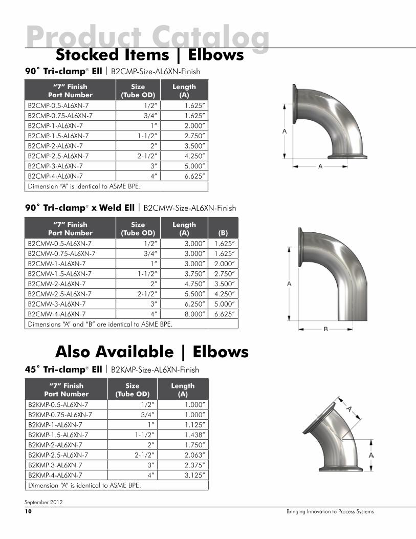
��Ý�7UL�FODPS® Ell | B2CMP-Size-AL6XN-Finish
��Ý�7UL�FODPS® x Weld Ell | B2CMW-Size-AL6XN-Finish
“7” Finish Part Number
Size (Tube OD)
Length (A)
B2CMP-0.5-AL6XN-7 1/2” 1.625”B2CMP-0.75-AL6XN-7 3/4” 1.625”B2CMP-1-AL6XN-7 1” 2.000”B2CMP-1.5-AL6XN-7 1-1/2” 2.750”B2CMP-2-AL6XN-7 2” 3.500”B2CMP-2.5-AL6XN-7 2-1/2” 4.250”B2CMP-3-AL6XN-7 3” 5.000”B2CMP-4-AL6XN-7 4” 6.625”Dimension “A” is identical to ASME BPE.
“7” Finish Part Number
Size (Tube OD)
Length (A)
(B)
B2CMW-0.5-AL6XN-7 1/2” 3.000” 1.625”B2CMW-0.75-AL6XN-7 3/4” 3.000” 1.625”B2CMW-1-AL6XN-7 1” 3.000” 2.000”B2CMW-1.5-AL6XN-7 1-1/2” 3.750” 2.750”B2CMW-2-AL6XN-7 2” 4.750” 3.500”B2CMW-2.5-AL6XN-7 2-1/2” 5.500” 4.250”B2CMW-3-AL6XN-7 3” 6.250” 5.000”B2CMW-4-AL6XN-7 4” 8.000” 6.625”Dimensions “A” and “B” are identical to ASME BPE.
Product CatalogStocked Items | Elbows
Bringing Innovation to Process Systems10
September 2012
��Ý�7UL�FODPS® Ell |�%�.03�6L]H�$/�;1�)LQLVK
“7” Finish Part Number
Size (Tube OD)
Length (A)
%�.03�����$/�;1�� 1/2” 1.000”%�.03������$/�;1�� 3/4” 1.000”%�.03���$/�;1�� 1” 1.125”%�.03�����$/�;1�� 1-1/2” 1.438”%�.03���$/�;1�� 2” 1.750”%�.03�����$/�;1�� 2-1/2” 2.063”%�.03���$/�;1�� 3” 2.375”%�.03���$/�;1�� 4” 3.125”Dimension “A” is identical to ASME BPE.
Also Available | Elbows
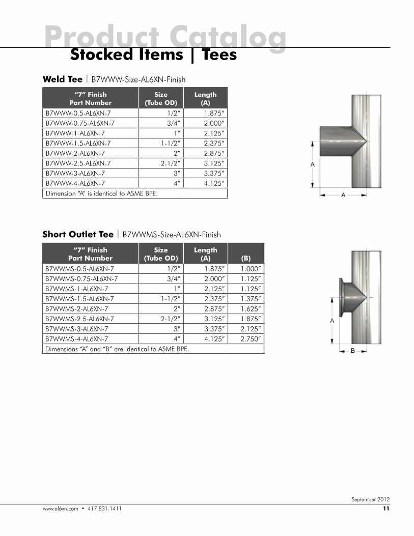
Weld Tee | B7WWW-Size-AL6XN-Finish
Short Outlet Tee | B7WWMS-Size-AL6XN-Finish
“7” Finish Part Number
Size (Tube OD)
Length (A)
B7WWW-0.5-AL6XN-7 1/2” 1.875”B7WWW-0.75-AL6XN-7 3/4” 2.000”B7WWW-1-AL6XN-7 1” 2.125”B7WWW-1.5-AL6XN-7 1-1/2” 2.375”B7WWW-2-AL6XN-7 2” 2.875”B7WWW-2.5-AL6XN-7 2-1/2” 3.125”B7WWW-3-AL6XN-7 3” 3.375”B7WWW-4-AL6XN-7 4” 4.125”Dimension “A” is identical to ASME BPE.
“7” Finish Part Number
Size (Tube OD)
Length (A)
(B)
B7WWMS-0.5-AL6XN-7 1/2” 1.875” 1.000”B7WWMS-0.75-AL6XN-7 3/4” 2.000” 1.125”B7WWMS-1-AL6XN-7 1” 2.125” 1.125”B7WWMS-1.5-AL6XN-7 1-1/2” 2.375” 1.375”B7WWMS-2-AL6XN-7 2” 2.875” 1.625”B7WWMS-2.5-AL6XN-7 2-1/2” 3.125” 1.875”B7WWMS-3-AL6XN-7 3” 3.375” 2.125”B7WWMS-4-AL6XN-7 4” 4.125” 2.750”Dimensions “A” and “B” are identical to ASME BPE.
Stocked Items | TeesProduct Catalog
ZZZ�DO�[Q�FRP����������������� 11
September 2012
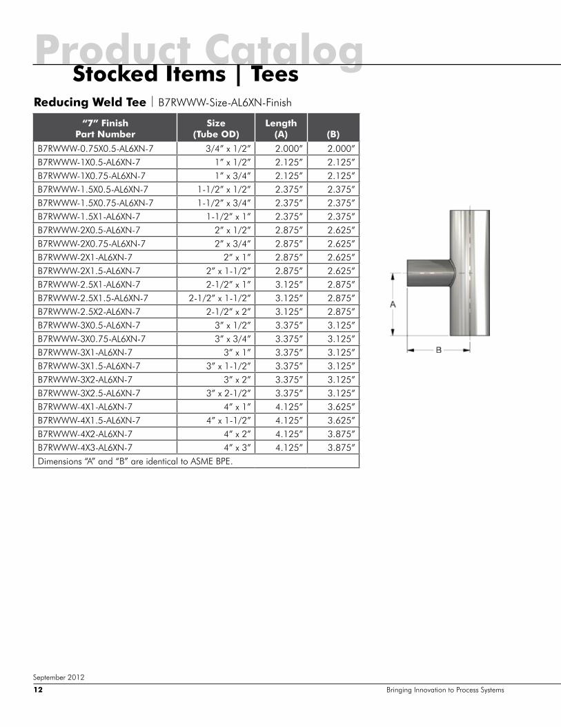
Reducing Weld Tee | B7RWWW-Size-AL6XN-Finish
“7” Finish Part Number
Size (Tube OD)
Length (A)
(B)
B7RWWW-0.75X0.5-AL6XN-7 3/4” x 1/2” 2.000” 2.000”B7RWWW-1X0.5-AL6XN-7 1” x 1/2” 2.125” 2.125”B7RWWW-1X0.75-AL6XN-7 1” x 3/4” 2.125” 2.125”B7RWWW-1.5X0.5-AL6XN-7 1-1/2” x 1/2” 2.375” 2.375”B7RWWW-1.5X0.75-AL6XN-7 1-1/2” x 3/4” 2.375” 2.375”B7RWWW-1.5X1-AL6XN-7 1-1/2” x 1” 2.375” 2.375”B7RWWW-2X0.5-AL6XN-7 2” x 1/2” 2.875” 2.625”B7RWWW-2X0.75-AL6XN-7 2” x 3/4” 2.875” 2.625”B7RWWW-2X1-AL6XN-7 2” x 1” 2.875” 2.625”B7RWWW-2X1.5-AL6XN-7 2” x 1-1/2” 2.875” 2.625”B7RWWW-2.5X1-AL6XN-7 2-1/2” x 1” 3.125” 2.875”B7RWWW-2.5X1.5-AL6XN-7 2-1/2” x 1-1/2” 3.125” 2.875”B7RWWW-2.5X2-AL6XN-7 2-1/2” x 2” 3.125” 2.875”B7RWWW-3X0.5-AL6XN-7 3” x 1/2” 3.375” 3.125”B7RWWW-3X0.75-AL6XN-7 3” x 3/4” 3.375” 3.125”B7RWWW-3X1-AL6XN-7 3” x 1” 3.375” 3.125”B7RWWW-3X1.5-AL6XN-7 3” x 1-1/2” 3.375” 3.125”B7RWWW-3X2-AL6XN-7 3” x 2” 3.375” 3.125”B7RWWW-3X2.5-AL6XN-7 3” x 2-1/2” 3.375” 3.125”B7RWWW-4X1-AL6XN-7 4” x 1” 4.125” 3.625”B7RWWW-4X1.5-AL6XN-7 4” x 1-1/2” 4.125” 3.625”B7RWWW-4X2-AL6XN-7 4” x 2” 4.125” 3.875”B7RWWW-4X3-AL6XN-7 4” x 3” 4.125” 3.875”Dimensions “A” and “B” are identical to ASME BPE.
Product CatalogStocked Items | Tees
Bringing Innovation to Process Systems12
September 2012
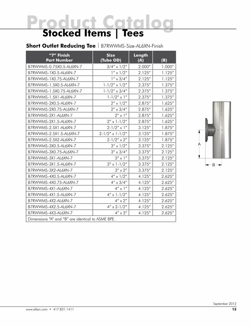
Short Outlet Reducing Tee | B7RWWMS-Size-AL6XN-Finish
“7” Finish Part Number
Size (Tube OD)
Length (A)
(B)
B7RWWMS-0.75X0.5-AL6XN-7 3/4” x 1/2” 2.000” 1.000”B7RWWMS-1X0.5-AL6XN-7 1” x 1/2” 2.125” 1.125”B7RWWMS-1X0.75-AL6XN-7 1” x 3/4” 2.125” 1.125”B7RWWMS-1.5X0.5-AL6XN-7 1-1/2” x 1/2” 2.375” 1.375”B7RWWMS-1.5X0.75-AL6XN-7 1-1/2” x 3/4” 2.375” 1.375”B7RWWMS-1.5X1-AL6XN-7 1-1/2” x 1” 2.375” 1.375”B7RWWMS-2X0.5-AL6XN-7 2” x 1/2” 2.875” 1.625”B7RWWMS-2X0.75-AL6XN-7 2” x 3/4” 2.875” 1.625”B7RWWMS-2X1-AL6XN-7 2” x 1” 2.875” 1.625”B7RWWMS-2X1.5-AL6XN-7 2” x 1-1/2” 2.875” 1.625”B7RWWMS-2.5X1-AL6XN-7 2-1/2” x 1” 3.125” 1.875”B7RWWMS-2.5X1.5-AL6XN-7 2-1/2” x 1-1/2” 3.125” 1.875”B7RWWMS-2.5X2-AL6XN-7 2-1/2” x 2” 3.125” 1.875”B7RWWMS-3X0.5-AL6XN-7 3” x 1/2” 3.375” 2.125”B7RWWMS-3X0.75-AL6XN-7 3” x 3/4” 3.375” 2.125”B7RWWMS-3X1-AL6XN-7 3” x 1” 3.375” 2.125”B7RWWMS-3X1.5-AL6XN-7 3” x 1-1/2” 3.375” 2.125”B7RWWMS-3X2-AL6XN-7 3” x 2” 3.375” 2.125”B7RWWMS-4X0.5-AL6XN-7 4” x 1/2” 4.125” 2.625”B7RWWMS-4X0.75-AL6XN-7 4” x 3/4” 4.125” 2.625”B7RWWMS-4X1-AL6XN-7 4” x 1” 4.125” 2.625”B7RWWMS-4X1.5-AL6XN-7 4” x 1-1/2” 4.125” 2.625”B7RWWMS-4X2-AL6XN-7 4” x 2” 4.125” 2.625”B7RWWMS-4X2.5-AL6XN-7 4” x 2-1/2” 4.125” 2.625”B7RWWMS-4X3-AL6XN-7 4” x 3” 4.125” 2.625”Dimensions “A” and “B” are identical to ASME BPE.
Product CatalogStocked Items | Tees
ZZZ�DO�[Q�FRP����������������� 13
September 2012
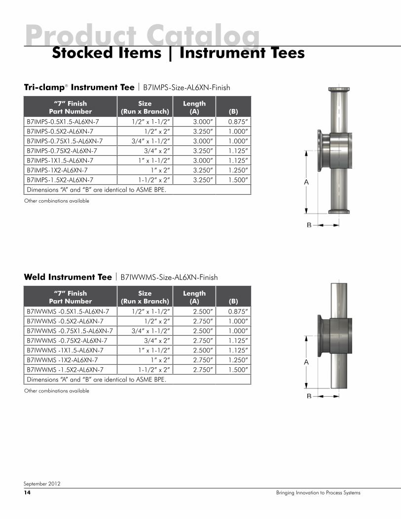
Tri-clamp® Instrument Tee | B7IMPS-Size-AL6XN-Finish
Weld Instrument Tee | B7IWWMS-Size-AL6XN-Finish
“7” Finish Part Number
Size (Run x Branch)
Length (A)
(B)
B7IMPS-0.5X1.5-AL6XN-7 1/2” x 1-1/2” 3.000” 0.875”B7IMPS-0.5X2-AL6XN-7 1/2” x 2” 3.250” 1.000”B7IMPS-0.75X1.5-AL6XN-7 3/4” x 1-1/2” 3.000” 1.000”B7IMPS-0.75X2-AL6XN-7 3/4” x 2” 3.250” 1.125”B7IMPS-1X1.5-AL6XN-7 1” x 1-1/2” 3.000” 1.125”B7IMPS-1X2-AL6XN-7 1” x 2” 3.250” 1.250”B7IMPS-1.5X2-AL6XN-7 1-1/2” x 2” 3.250” 1.500”Dimensions “A” and “B” are identical to ASME BPE.
“7” Finish Part Number
Size (Run x Branch)
Length (A)
(B)
B7IWWMS -0.5X1.5-AL6XN-7 1/2” x 1-1/2” 2.500” 0.875”B7IWWMS -0.5X2-AL6XN-7 1/2” x 2” 2.750” 1.000”B7IWWMS -0.75X1.5-AL6XN-7 3/4” x 1-1/2” 2.500” 1.000”B7IWWMS -0.75X2-AL6XN-7 3/4” x 2” 2.750” 1.125”B7IWWMS -1X1.5-AL6XN-7 1” x 1-1/2” 2.500” 1.125”B7IWWMS -1X2-AL6XN-7 1” x 2” 2.750” 1.250”B7IWWMS -1.5X2-AL6XN-7 1-1/2” x 2” 2.750” 1.500”Dimensions “A” and “B” are identical to ASME BPE.
Product CatalogStocked Items | Instrument Tees
Bringing Innovation to Process Systems14
September 2012
Other combinations available
Other combinations available

Weld True Y | 28BW-Size-AL6XN-Finish
Tri-clamp® True Y | 28BMP-Size-AL6XN-Finish
Weld Lateral | 28WA-Size-AL6XN-Finish
Tri-clamp® Lateral | 28AMP-Size-AL6XN-Finish
“7” Finish Part Number Size (Tube OD) Length (A)
28BW-1-AL6XN-7 1” 2.000”28BW-1.5-AL6XN-7 1-1/2” 3.000”28BW-2-AL6XN-7 2” 4.000”28BW-2.5-AL6XN-7 2-1/2” 4.500”28BW-3-AL6XN-7 3” 5.000”28BW-4-AL6XN-7 4” 7.000”
“7” Finish Part Number Size (Tube OD) Length (A)
28BMP-1-AL6XN-7 1” 2.500”28BMP-1.5-AL6XN-7 1-1/2” 3.500”28BMP-2-AL6XN-7 2” 4.500”28BMP-2.5-AL6XN-7 2-1/2” 5.000”28BMP-3-AL6XN-7 3” 5.500”28BMP-4-AL6XN-7 4” 7.625”
“7” Finish Part Number Size (Tube OD) Length (A) (B)
28WA-1-AL6XN-7 1” 5.000” 7.500”28WA-1.5-AL6XN-7 1-1/2” 5.000” 7.500”28WA-2-AL6XN-7 2” 6.000” 9.000”28WA-2.5-AL6XN-7 2-1/2” 6.500” 9.750”28WA-3-AL6XN-7 3” 7.000” 10.500”28WA-4-AL6XN-7 4” 9.000” 13.500”
“7” Finish Part Number
Size (Tube OD) Length (A) (B)
28AMP-1-AL6XN-7 1” 5.500” 8.500”28AMP-1.5-AL6XN-7 1-1/2” 5.500” 8.500”28AMP-2-AL6XN-7 2” 6.500” 10.000”28AMP-2.5-AL6XN-7 2-1/2” 7.000” 10.750”28AMP-3-AL6XN-7 3” 7.500” 11.500”28AMP-4-AL6XN-7 4” 9.625” 14.750”
Product CatalogAlso Available | True and Lateral Ys
ZZZ�DO�[Q�FRP����������������� 15
September 2012
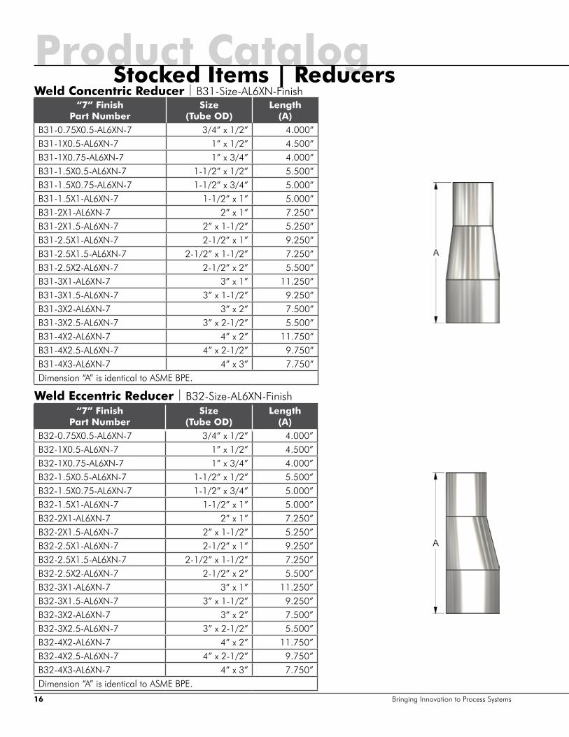
Weld Concentric Reducer | B31-Size-AL6XN-Finish
Weld Eccentric Reducer | B32-Size-AL6XN-Finish
“7” Finish Part Number
Size (Tube OD)
Length (A)
B31-0.75X0.5-AL6XN-7 3/4” x 1/2” 4.000”B31-1X0.5-AL6XN-7 1” x 1/2” 4.500”B31-1X0.75-AL6XN-7 1” x 3/4” 4.000”B31-1.5X0.5-AL6XN-7 1-1/2” x 1/2” 5.500”B31-1.5X0.75-AL6XN-7 1-1/2” x 3/4” 5.000”B31-1.5X1-AL6XN-7 1-1/2” x 1” 5.000”B31-2X1-AL6XN-7 2” x 1” 7.250”B31-2X1.5-AL6XN-7 2” x 1-1/2” 5.250”B31-2.5X1-AL6XN-7 2-1/2” x 1” 9.250”B31-2.5X1.5-AL6XN-7 2-1/2” x 1-1/2” 7.250”B31-2.5X2-AL6XN-7 2-1/2” x 2” 5.500”B31-3X1-AL6XN-7 3” x 1” 11.250”B31-3X1.5-AL6XN-7 3” x 1-1/2” 9.250”B31-3X2-AL6XN-7 3” x 2” 7.500”B31-3X2.5-AL6XN-7 3” x 2-1/2” 5.500”B31-4X2-AL6XN-7 4” x 2” 11.750”B31-4X2.5-AL6XN-7 4” x 2-1/2” 9.750”B31-4X3-AL6XN-7 4” x 3” 7.750”Dimension “A” is identical to ASME BPE.
“7” Finish Part Number
Size (Tube OD)
Length (A)
B32-0.75X0.5-AL6XN-7 3/4” x 1/2” 4.000”B32-1X0.5-AL6XN-7 1” x 1/2” 4.500”B32-1X0.75-AL6XN-7 1” x 3/4” 4.000”B32-1.5X0.5-AL6XN-7 1-1/2” x 1/2” 5.500”B32-1.5X0.75-AL6XN-7 1-1/2” x 3/4” 5.000”B32-1.5X1-AL6XN-7 1-1/2” x 1” 5.000”B32-2X1-AL6XN-7 2” x 1” 7.250”B32-2X1.5-AL6XN-7 2” x 1-1/2” 5.250”B32-2.5X1-AL6XN-7 2-1/2” x 1” 9.250”B32-2.5X1.5-AL6XN-7 2-1/2” x 1-1/2” 7.250”B32-2.5X2-AL6XN-7 2-1/2” x 2” 5.500”B32-3X1-AL6XN-7 3” x 1” 11.250”B32-3X1.5-AL6XN-7 3” x 1-1/2” 9.250”B32-3X2-AL6XN-7 3” x 2” 7.500”B32-3X2.5-AL6XN-7 3” x 2-1/2” 5.500”B32-4X2-AL6XN-7 4” x 2” 11.750”B32-4X2.5-AL6XN-7 4” x 2-1/2” 9.750”B32-4X3-AL6XN-7 4” x 3” 7.750”Dimension “A” is identical to ASME BPE.
Product CatalogStocked Items | Reducers
Bringing Innovation to Process Systems16
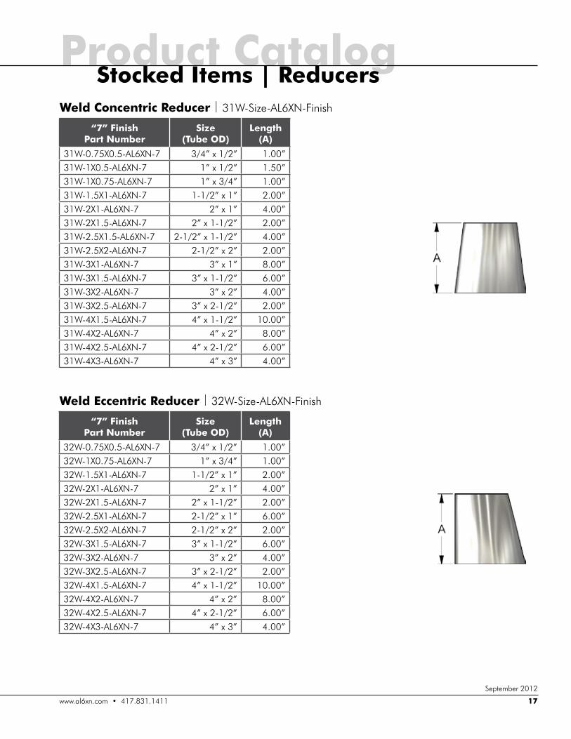
Weld Concentric Reducer | 31W-Size-AL6XN-Finish
Weld Eccentric Reducer | 32W-Size-AL6XN-Finish
“7” Finish Part Number
Size (Tube OD)
Length (A)
31W-0.75X0.5-AL6XN-7 3/4” x 1/2” 1.00”31W-1X0.5-AL6XN-7 1” x 1/2” 1.50”31W-1X0.75-AL6XN-7 1” x 3/4” 1.00”31W-1.5X1-AL6XN-7 1-1/2” x 1” 2.00”31W-2X1-AL6XN-7 2” x 1” 4.00”31W-2X1.5-AL6XN-7 2” x 1-1/2” 2.00”31W-2.5X1.5-AL6XN-7 2-1/2” x 1-1/2” 4.00”31W-2.5X2-AL6XN-7 2-1/2” x 2” 2.00”31W-3X1-AL6XN-7 3” x 1” 8.00”31W-3X1.5-AL6XN-7 3” x 1-1/2” 6.00”31W-3X2-AL6XN-7 3” x 2” 4.00”31W-3X2.5-AL6XN-7 3” x 2-1/2” 2.00”31W-4X1.5-AL6XN-7 4” x 1-1/2” 10.00”31W-4X2-AL6XN-7 4” x 2” 8.00”31W-4X2.5-AL6XN-7 4” x 2-1/2” 6.00”31W-4X3-AL6XN-7 4” x 3” 4.00”
“7” Finish Part Number
Size (Tube OD)
Length (A)
32W-0.75X0.5-AL6XN-7 3/4” x 1/2” 1.00”32W-1X0.75-AL6XN-7 1” x 3/4” 1.00”32W-1.5X1-AL6XN-7 1-1/2” x 1” 2.00”32W-2X1-AL6XN-7 2” x 1” 4.00”32W-2X1.5-AL6XN-7 2” x 1-1/2” 2.00”32W-2.5X1-AL6XN-7 2-1/2” x 1” 6.00”32W-2.5X2-AL6XN-7 2-1/2” x 2” 2.00”32W-3X1.5-AL6XN-7 3” x 1-1/2” 6.00”32W-3X2-AL6XN-7 3” x 2” 4.00”32W-3X2.5-AL6XN-7 3” x 2-1/2” 2.00”32W-4X1.5-AL6XN-7 4” x 1-1/2” 10.00”32W-4X2-AL6XN-7 4” x 2” 8.00”32W-4X2.5-AL6XN-7 4” x 2-1/2” 6.00”32W-4X3-AL6XN-7 4” x 3” 4.00”
Product CatalogStocked Items | Reducers
ZZZ�DO�[Q�FRP����������������� 17
September 2012
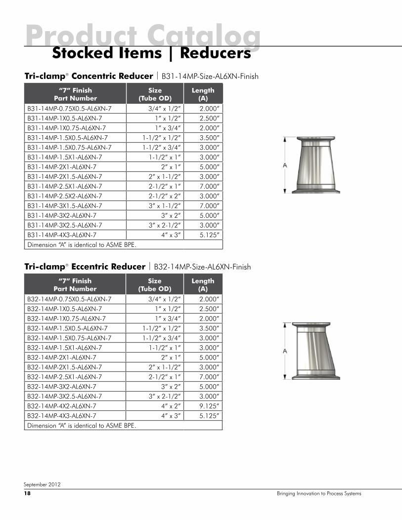
Tri-clamp® Concentric Reducer | B31-14MP-Size-AL6XN-Finish
Tri-clamp® Eccentric Reducer | B32-14MP-Size-AL6XN-Finish
“7” Finish Part Number
Size (Tube OD)
Length (A)
B31-14MP-0.75X0.5-AL6XN-7 3/4” x 1/2” 2.000”B31-14MP-1X0.5-AL6XN-7 1” x 1/2” 2.500”B31-14MP-1X0.75-AL6XN-7 1” x 3/4” 2.000”B31-14MP-1.5X0.5-AL6XN-7 1-1/2” x 1/2” 3.500”B31-14MP-1.5X0.75-AL6XN-7 1-1/2” x 3/4” 3.000”B31-14MP-1.5X1-AL6XN-7 1-1/2” x 1” 3.000”B31-14MP-2X1-AL6XN-7 2” x 1” 5.000”B31-14MP-2X1.5-AL6XN-7 2” x 1-1/2” 3.000”B31-14MP-2.5X1-AL6XN-7 2-1/2” x 1” 7.000”B31-14MP-2.5X2-AL6XN-7 2-1/2” x 2” 3.000”B31-14MP-3X1.5-AL6XN-7 3” x 1-1/2” 7.000”B31-14MP-3X2-AL6XN-7 3” x 2” 5.000”B31-14MP-3X2.5-AL6XN-7 3” x 2-1/2” 3.000”B31-14MP-4X3-AL6XN-7 4” x 3” 5.125”Dimension “A” is identical to ASME BPE.
“7” Finish Part Number
Size (Tube OD)
Length (A)
B32-14MP-0.75X0.5-AL6XN-7 3/4” x 1/2” 2.000”B32-14MP-1X0.5-AL6XN-7 1” x 1/2” 2.500”B32-14MP-1X0.75-AL6XN-7 1” x 3/4” 2.000”B32-14MP-1.5X0.5-AL6XN-7 1-1/2” x 1/2” 3.500”B32-14MP-1.5X0.75-AL6XN-7 1-1/2” x 3/4” 3.000”B32-14MP-1.5X1-AL6XN-7 1-1/2” x 1” 3.000”B32-14MP-2X1-AL6XN-7 2” x 1” 5.000”B32-14MP-2X1.5-AL6XN-7 2” x 1-1/2” 3.000”B32-14MP-2.5X1-AL6XN-7 2-1/2” x 1” 7.000”B32-14MP-3X2-AL6XN-7 3” x 2” 5.000”B32-14MP-3X2.5-AL6XN-7 3” x 2-1/2” 3.000”B32-14MP-4X2-AL6XN-7 4” x 2” 9.125”B32-14MP-4X3-AL6XN-7 4” x 3” 5.125”Dimension “A” is identical to ASME BPE.
Product CatalogStocked Items | Reducers
Bringing Innovation to Process Systems18
September 2012

Tri-clamp® x Butt Weld Concentric Reducer | B31M-Size-AL6XN-Finish
Tri-clamp® x Butt Weld Eccentric Reducer | B32M-Size-AL6XN-Finish
“7” Finish Part Number
Size (Tube OD)
Length (A)
B31M-0.75X0.5-AL6XN-7 3/4” x 1/2” 3.000”B31M-1X0.5-AL6XN-7 1” x 1/2” 3.500”B31M-1X0.75-AL6XN-7 1” x 3/4” 3.000”B31M-1.5X0.75-AL6XN-7 1-1/2” x 3/4” 4.000”B31M-1.5X1-AL6XN-7 1-1/2” x 1” 4.000”B31M-2X1-AL6XN-7 2” x 1” 6.000”B31M-2X1.5-AL6XN-7 2” x 1-1/2” 4.000”B31M-2.5X1.5-AL6XN-7 2-1/2” x 1-1/2” 6.000”B31M-2.5X2-AL6XN-7 2-1/2” x 2” 4.250”B31M-3X2-AL6XN-7 3” x 2” 6.250”B31M-3X2.5-AL6XN-7 3” x 2-1/2” 4.250”B31M-4X2.5-AL6XN-7 4” x 2-1/2” 8.375”B31M-4X3-AL6XN-7 4” x 3” 6.375”Dimension “A” is identical to ASME BPE.
“7” Finish Part Number
Size (Tube OD)
Length (A)
B32M-0.75X0.5-AL6XN-7 3/4” x 1/2” 3.000”B32M-1X0.5-AL6XN-7 1” x 1/2” 3.500”B32M-1X0.75-AL6XN-7 1” x 3/4” 3.000”B32M-1.5X0.75-AL6XN-7 1-1/2” x 3/4” 4.000”B32M-1.5X1-AL6XN-7 1-1/2” x 1” 4.000”B32M-2X1-AL6XN-7 2” x 1” 6.000”B32M-2X1.5-AL6XN-7 2” x 1-1/2” 4.000”B32M-2.5X1.5-AL6XN-7 2-1/2” x 1-1/2” 6.000”B32M-2.5X2-AL6XN-7 2-1/2” x 2” 4.250”B32M-3X2-AL6XN-7 3” x 2” 6.250”B32M-3X2.5-AL6XN-7 3” x 2-1/2” 4.250”B32M-4X2.5-AL6XN-7 4” x 2-1/2” 8.375”B32M-4X3-AL6XN-7 4” x 3” 6.375”Dimension “A” is identical to ASME BPE.
Product CatalogStocked Items | Reducers
ZZZ�DO�[Q�FRP����������������� 19
September 2012
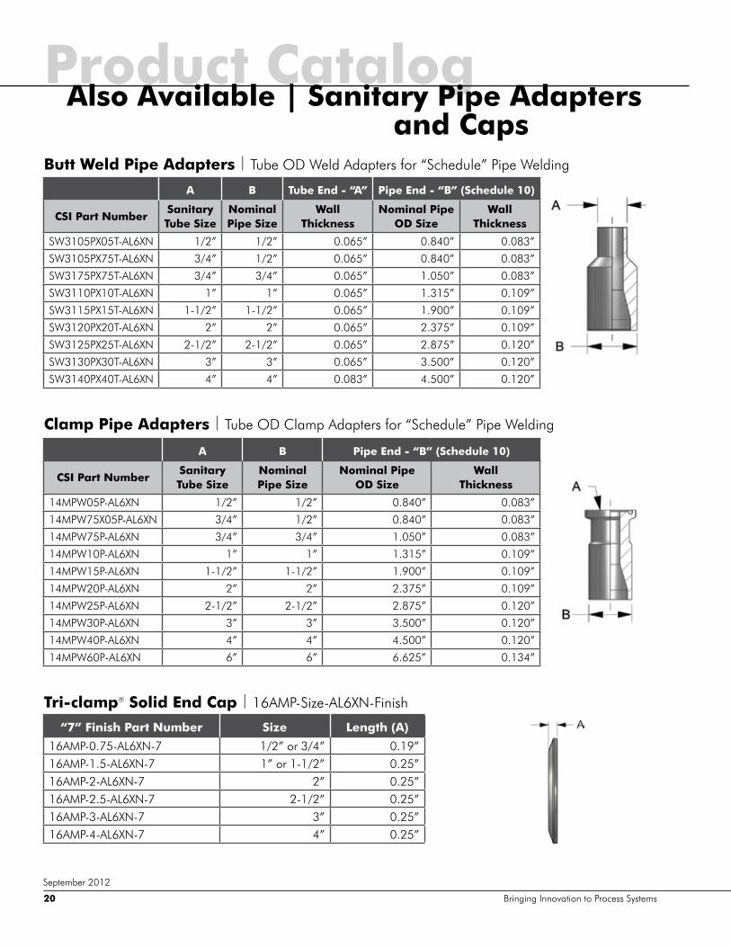
Butt Weld Pipe Adapters | Tube OD Weld Adapters for “Schedule” Pipe Welding
A B Tube End - “A” Pipe End - “B” (Schedule 10)
CSI Part NumberSanitary Tube Size
Nominal Pipe Size
Wall Thickness
Nominal Pipe OD Size
Wall Thickness
SW3105PX05T-AL6XN 1/2” 1/2” 0.065” 0.840” 0.083”
SW3105PX75T-AL6XN 3/4” 1/2” 0.065” 0.840” 0.083”
SW3175PX75T-AL6XN 3/4” 3/4” 0.065” 1.050” 0.083”
SW3110PX10T-AL6XN 1” 1” 0.065” 1.315” 0.109”
SW3115PX15T-AL6XN 1-1/2” 1-1/2” 0.065” 1.900” 0.109”
SW3120PX20T-AL6XN 2” 2” 0.065” 2.375” 0.109”
SW3125PX25T-AL6XN 2-1/2” 2-1/2” 0.065” 2.875” 0.120”
SW3130PX30T-AL6XN 3” 3” 0.065” 3.500” 0.120”
SW3140PX40T-AL6XN 4” 4” 0.083” 4.500” 0.120”
Clamp Pipe Adapters | Tube OD Clamp Adapters for “Schedule” Pipe Welding
A B Pipe End - “B” (Schedule 10)
CSI Part NumberSanitary Tube Size
Nominal Pipe Size
Nominal Pipe OD Size
Wall Thickness
14MPW05P-AL6XN 1/2” 1/2” 0.840” 0.083”
14MPW75X05P-AL6XN 3/4” 1/2” 0.840” 0.083”
14MPW75P-AL6XN 3/4” 3/4” 1.050” 0.083”
14MPW10P-AL6XN 1” 1” 1.315” 0.109”
14MPW15P-AL6XN 1-1/2” 1-1/2” 1.900” 0.109”
14MPW20P-AL6XN 2” 2” 2.375” 0.109”
14MPW25P-AL6XN 2-1/2” 2-1/2” 2.875” 0.120”
14MPW30P-AL6XN 3” 3” 3.500” 0.120”
14MPW40P-AL6XN 4” 4” 4.500” 0.120”
14MPW60P-AL6XN 6” 6” 6.625” 0.134”
Product CatalogAlso Available | Sanitary Pipe Adapters and Caps
Tri-clamp® Solid End Cap | 16AMP-Size-AL6XN-Finish
“7” Finish Part Number Size Length (A)
16AMP-0.75-AL6XN-7 1/2” or 3/4” 0.19”16AMP-1.5-AL6XN-7 1” or 1-1/2” 0.25”16AMP-2-AL6XN-7 2” 0.25”16AMP-2.5-AL6XN-7 2-1/2” 0.25”16AMP-3-AL6XN-7 3” 0.25”16AMP-4-AL6XN-7 4” 0.25”
Bringing Innovation to Process Systems20
September 2012
ZZZ�DO�[Q�FRP����������������� 21
6HSWHPEHU�����
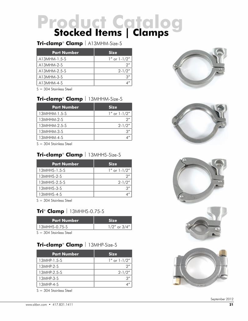
Tri-clamp® Clamp |���0++6�6L]H�6
6� �����6WDLQOHVV�6WHHO
Part Number Size
��0++6�����6 �µ�RU������µ��0++6���6 �µ��0++6�����6 �����µ��0++6���6 �µ��0++6���6 �µ
Tri® Clamp |���0++6������6
6� �����6WDLQOHVV�6WHHO
Part Number Size
��0++6������6 ���µ�RU����µ
Tri-clamp® Clamp |���0+3�6L]H�6
6� �����6WDLQOHVV�6WHHO
Part Number Size
��0+3�����6 �µ�RU������µ��0+3���6 �µ��0+3�����6 �����µ��0+3���6 �µ��0+3���6 �µ
Tri-clamp® Clamp |�$��0+0�6L]H�6
6� �����6WDLQOHVV�6WHHO
Part Number Size
$��0+0�����6 �µ�RU������µ$��0+0���6 �µ$��0+0�����6 �����µ$��0+0���6 �µ$��0+0���6 �µ
Product CatalogStocked Items | Clamps
Tri-clamp® Clamp |���0++0�6L]H�6
6� �����6WDLQOHVV�6WHHO
Part Number Size
��0++0�����6 �µ�RU������µ��0++0���6 �µ��0++0�����6 �����µ��0++0���6 �µ��0++0���6 �µ
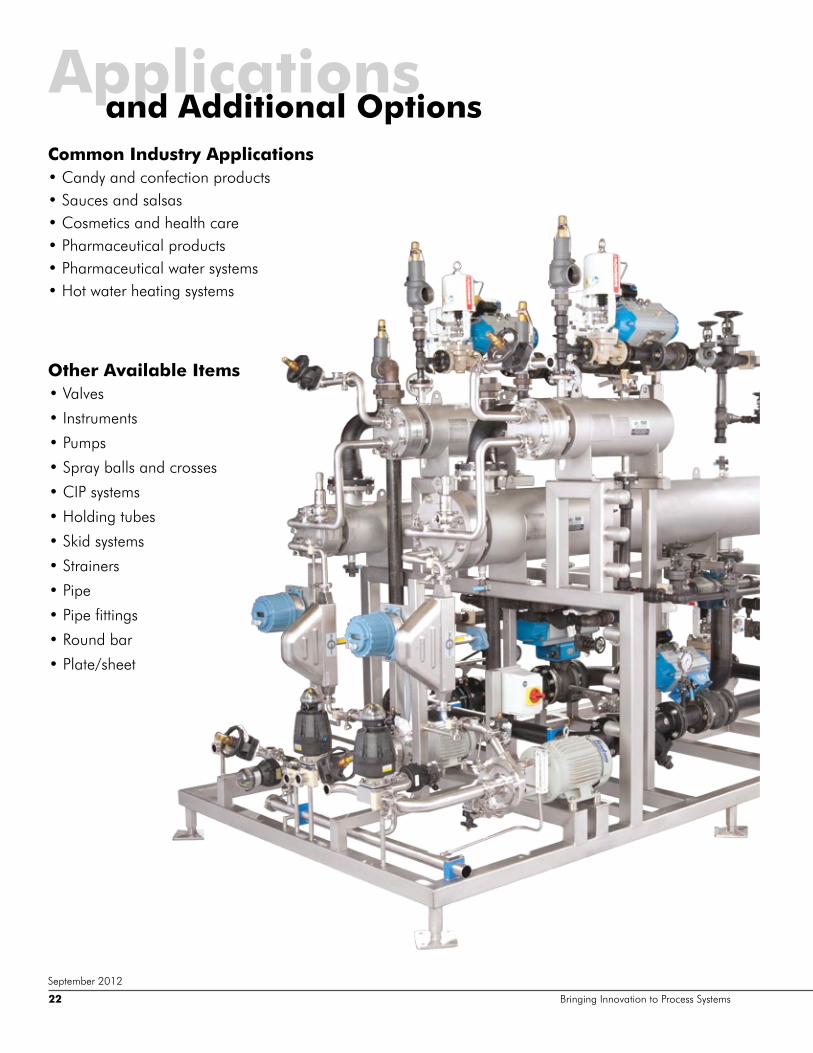
Applicationsand Additional Options
Bringing Innovation to Process Systems22
September 2012
Common Industry Applications��&DQG\�DQG�FRQIHFWLRQ�SURGXFWV��6DXFHV�DQG�VDOVDV��&RVPHWLFV�DQG�KHDOWK�FDUH��3KDUPDFHXWLFDO�SURGXFWV��3KDUPDFHXWLFDO�ZDWHU�V\VWHPV ��+RW�ZDWHU�KHDWLQJ�V\VWHPV�
Other Available Items��9DOYHV
��,QVWUXPHQWV
��3XPSV
��6SUD\�EDOOV�DQG�FURVVHV
��&,3�V\VWHPV
��+ROGLQJ�WXEHV
��6NLG�V\VWHPV
��6WUDLQHUV�
��3LSH
��3LSH�ILWWLQJV
��5RXQG�EDU
��3ODWH�VKHHW
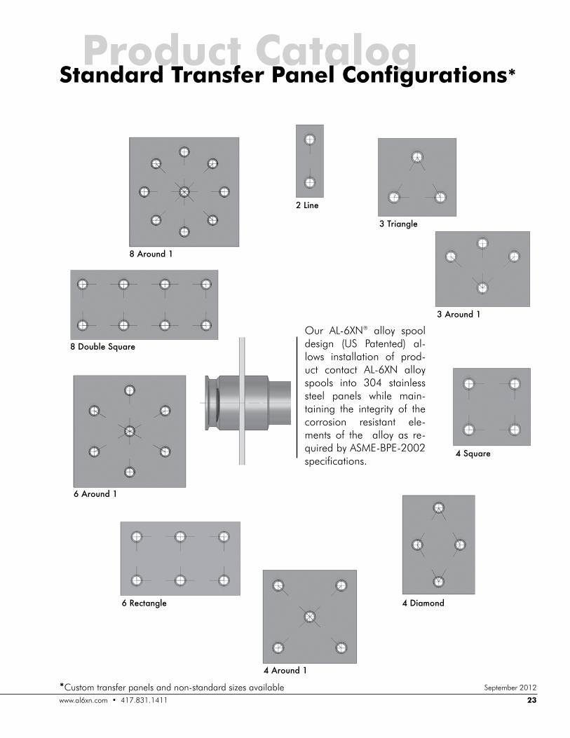
Our AL-6XN® alloy spool design (US Patented) al-lows installation of prod-uct contact AL-6XN alloy spools into 304 stainless steel panels while main-taining the integrity of the corrosion resistant ele-ments of the alloy as re-quired by ASME-BPE-2002 specifications.
2 Line
,�MkbZg`e^
,�:khng]�*
4 Square
4 Diamond
4 Around 1
6 Rectangle
6 Around 1
1�=hn[e^�LjnZk^
1�:khng]�*
Product CatalogStandard Transfer Panel Configurations*
*Custom transfer panels and non-standard sizes availableZZZ�DO�[Q�FRP����������������� 23
September 2012
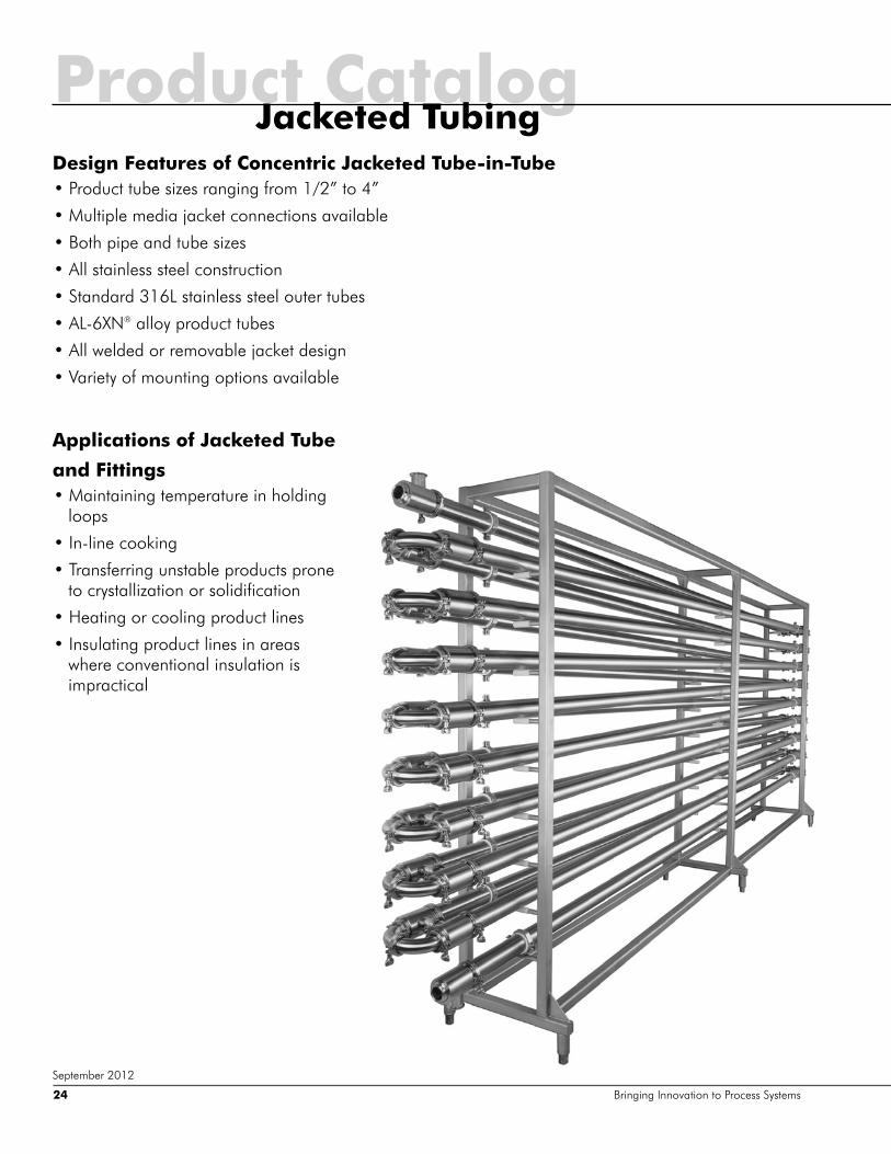
Design Features of Concentric Jacketed Tube-in-Tube��3URGXFW�WXEH�VL]HV�UDQJLQJ�IURP����µ�WR��µ
��0XOWLSOH�PHGLD�MDFNHW�FRQQHFWLRQV�DYDLODEOH
��%RWK�SLSH�DQG�WXEH�VL]HV
��$OO�VWDLQOHVV�VWHHO�FRQVWUXFWLRQ
��6WDQGDUG����/�VWDLQOHVV�VWHHO�RXWHU�WXEHV
��$/��;1® alloy product tubes
��$OO�ZHOGHG�RU�UHPRYDEOH�MDFNHW�GHVLJQ
��9DULHW\�RI�PRXQWLQJ�RSWLRQV�DYDLODEOH
Applications of Jacketed Tube
and Fittings��0DLQWDLQLQJ�WHPSHUDWXUH�LQ�KROGLQJ�
loops
��,Q�OLQH�FRRNLQJ
��7UDQVIHUULQJ�XQVWDEOH�SURGXFWV�SURQH�to crystallization or solidification
��+HDWLQJ�RU�FRROLQJ�SURGXFW�OLQHV
��,QVXODWLQJ�SURGXFW�OLQHV�LQ�DUHDV�where conventional insulation is impractical
Product CatalogJacketed Tubing
Bringing Innovation to Process Systems24
September 2012
WeldingAL-6XN®
General Welding Recommendations
AL-6XN alloy is easily welded using similar weld parameters as Type 316L stainless steel, including travel speed (IPM) and weld current. It is typically suggested to use weld inserts for additional alloy-ing when orbital or manual welding in the field.
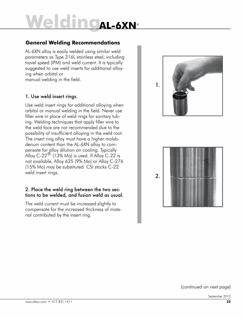
*'�Nl^�p^e]�bgl^km�kbg`l'
Use weld insert rings for additional alloying when orbital or manual welding in the field. Never use filler wire in place of weld rings for sanitary tub-ing. Welding techniques that apply filler wire to the weld face are not recommended due to the possibility of insufficient alloying in the weld root. The insert ring alloy must have a higher molyb-denum content than the AL-6XN alloy to com-pensate for alloy dilution on cooling. Typically Alloy C-22® (13% Mo) is used. If Alloy C-22 is not available, Alloy 625 (9% Mo) or Alloy C-276 (15% Mo) may be substituted. CSI stocks C-22 weld insert rings.
+'�Place the weld ring between the two sec-mbhgl�mh�[^�p^e]^]%�Zg]�_nlbhg�p^e]�Zl�nlnZe'
The weld current must be increased slightly to compensate for the increased thickness of mate-rial contributed by the insert ring.
*'
+'
ZZZ�DO�[Q�FRP����������������� 25
September 2012
(continued on next page)
WeldingAL-6XN®
,'
-'
Bringing Innovation to Process Systems26
General Welding Recommendations(continued)
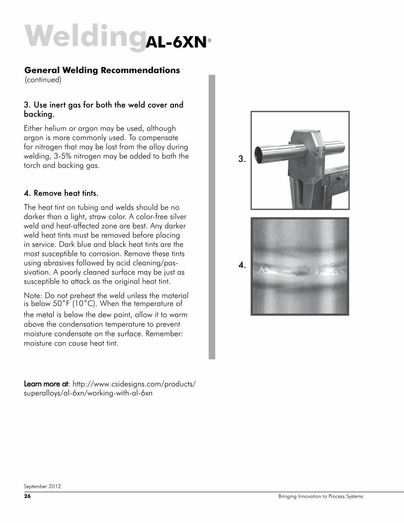
,'�Nl^�bg^km�`Zl�_hk�[hma�ma^�p^e]�\ho^k�Zg]� [Z\dbg`'
Either helium or argon may be used, although argon is more commonly used. To compensate for nitrogen that may be lost from the alloy during welding, 3-5% nitrogen may be added to both the torch and backing gas.
-'�K^fho^�a^Zm�mbgml'
The heat tint on tubing and welds should be no darker than a light, straw color. A color-free silver weld and heat-affected zone are best. Any darker weld heat tints must be removed before placing in service. Dark blue and black heat tints are the most susceptible to corrosion. Remove these tints using abrasives followed by acid cleaning/pas-sivation. A poorly cleaned surface may be just as susceptible to attack as the original heat tint.
Note: Do not preheat the weld unless the material LV�EHORZ���Ý)����Ý&���:KHQ�WKH�WHPSHUDWXUH�RI�the metal is below the dew point, allow it to warm above the condensation temperature to prevent moisture condensate on the surface. Remember: moisture can cause heat tint.
Learn more at: http://www.csidesigns.com/products/superalloys/al-6xn/working-with-al-6xn
September 2012

WeldingSpecial Welding RequirementsIf post-weld annealing is not possible, then an addi-tional alloy must be added to the weld. We call this an over-alloyed weld. Although AL-6XN alloy is classified as a single-phase alloy, when it is melted—as in weld-ing—it will solidify as a three-phase alloy: austenite, chi phase, and delta ferrite.
Chi phase, a chromium-iron-molybdenum com-pound, depletes the grain boundary in molybdenum and chromium, which reduces corrosion resistance. Delta ferrite also exhibits poor corrosion resistance. When over-alloyed by using weld insert rings or fill-er, the alloy balance and, therefore, the corrosion resistance of the weld is equal to or better than the base alloy.
When autogenous welding, chemical microsegregation in welds causes regions to be more susceptible to local-ized corrosion. Autogenous welding may be used with the following precautions:
��3RVW�ZHOG�DQQHDOLQJ�LV�UHTXLUHG��$QQHDO�DERYH�����Ý)������Ý&�� IROORZHG�E\� UDSLG�FRROLQJ�DQG�SLFNOLQJ� LI�D�protective annealing atmosphere is not used.
��7KH�GXUDWLRQ�RI�DQQHDO��DW�OHDVW�ILYH�PLQXWHV�DW�WHPSHUD-ture, must be sufficient to re-homogenize the weld seg-regation and to dissolve any chi phase.
��8VH�PL[HG�JDVHV�ZLWK�D�QLWURJHQ�YROXPH�RI������ IRU�weld shielding.
�� 7KH� *���%� FUHYLFH� WHVW� PD\� EH� XVHG� WR� DVVHVV� WKH�quality of autogenously welded and annealed AL-6XN alloy.
In many applications, a post-weld anneal and pickle may not be possible, like in large vessel fabrication or field welding of piping systems. In these cases, the ex-posure conditions must be carefully reviewed to deter-mine if autogenous welds are satisfactory. Autogenous AL-6XN alloy welds are more resistant to corrosion than similar welds in Types 316L, 317L, and 904L. Such au-togenous AL-6XN alloy welds have a corrosion resis-tance that is approximately the same as that of Alloy 904L base metal, and superior to that of Types 316L and 317L base metal.
AL-6XN®
Autogenous Welding (without filler)
ZZZ�DO�[Q�FRP����������������� 27
September 2012
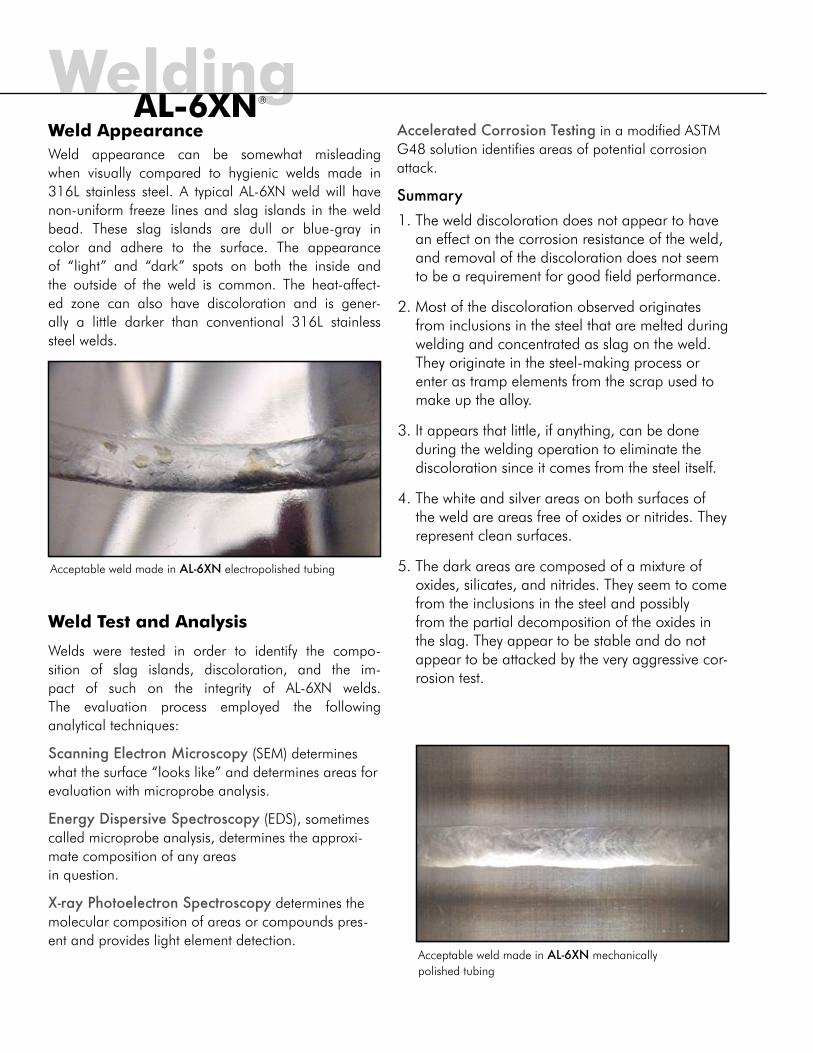
WeldingWeld AppearanceWeld appearance can be somewhat misleading when visually compared to hygienic welds made in 316L stainless steel. A typical AL-6XN weld will have non-uniform freeze lines and slag islands in the weld bead. These slag islands are dull or blue-gray in color and adhere to the surface. The appearance of “light” and “dark” spots on both the inside and the outside of the weld is common. The heat-affect-ed zone can also have discoloration and is gener-ally a little darker than conventional 316L stainless steel welds.
Weld Test and Analysis
Welds were tested in order to identify the compo-sition of slag islands, discoloration, and the im-pact of such on the integrity of AL-6XN welds. The evaluation process employed the following analytical techniques:
Scanning Electron Microscopy (SEM) determines what the surface “looks like” and determines areas for evaluation with microprobe analysis.
Energy Dispersive Spectroscopy (EDS), sometimes called microprobe analysis, determines the approxi-mate composition of any areas in question.
X-ray Photoelectron Spectroscopy determines the molecular composition of areas or compounds pres-ent and provides light element detection.
Accelerated Corrosion Testing in a modified ASTM G48 solution identifies areas of potential corrosion attack.
Summary1. The weld discoloration does not appear to have
an effect on the corrosion resistance of the weld, and removal of the discoloration does not seem to be a requirement for good field performance.
2. Most of the discoloration observed originates from inclusions in the steel that are melted during welding and concentrated as slag on the weld. They originate in the steel-making process or enter as tramp elements from the scrap used to make up the alloy.
3. It appears that little, if anything, can be done during the welding operation to eliminate the discoloration since it comes from the steel itself.
4. The white and silver areas on both surfaces of the weld are areas free of oxides or nitrides. They represent clean surfaces.
5. The dark areas are composed of a mixture of oxides, silicates, and nitrides. They seem to come from the inclusions in the steel and possibly from the partial decomposition of the oxides in the slag. They appear to be stable and do not appear to be attacked by the very aggressive cor-rosion test.
Acceptable weld made in AL-6XN electropolished tubing
Acceptable weld made in AL-6XN mechanically polished tubing
AL-6XN®

Trademarks1. AL-6XN is a registered trademark of ATI Properties, Inc., licensed to Allegheny Ludlum Group.2. Hastelloy and C-22 are registered trademarks of Haynes International.
©2012 Central States Industrial Equipment & Service, Inc. All rights reserved. No reproduction without permission of the author.
References1. AL-6XN® alloy PHYSICAL, MECHANICAL and CORROSION PROPERTIES, Bulletin No. 210, Rolled Alloys2. Hastelloy®�DOOR\�&������%XOOHWLQ�+�����%��+D\QHV�,QWHUQDWLRQDO��.RNRPR��,QGLDQD3. INCONEL alloy 625, Bulletin T-42, Huntington Alloys Inc., Huntington, West Virginia4. Private correspondence, Carpenter Technology Corporation, 1991
Bringing Innovation To Process Systems
CSI’s experience, knowledge, and commitment of resources have put us in a unique position to serve and support customers with special alloy needs. We are constantly seeking to improve our understanding of corrosion problems faced by processors and how we can provide solutions.
Our three facilities located in Springfield, MO; Fowler, CA; and Morrisville, NC enable us to ship our products coast to coast in a timely manner. To find out more about CSI, our products and services, or how we can help you succeed, give us a call at 417.831.1411 or toll free at 800.654.5635.
CSI | 2700 N Partnership Blvd Springfield, Missouri 65803 | www.al6xn.com
CSI
AL 08/12 5H


