AFRL-RQ-WP-TR-2017-0047
ALTERNATIVE AVIATION FUELS FOR USE IN
MILITARY APUS AND ENGINES VERSATILE AFFORDABLE ADVANCED TURBINE ENGINE (VAATE), PHASE II AND IIIDelivery Order 0007: Alternative Aviation Fuels for Use in Military Auxiliary Power Units (APUs) and Engines
Brad Culbertson and Randy Williams
Honeywell International Inc.
MARCH 2017
Final Report
DISTRIBUTION STATEMENT A: Approved for public release. Distribution is unlimited.
See additional restrictions described on inside pages.
AIR FORCE RESEARCH LABORATORY
AEROSPACE SYSTEMS DIRECTORATE
WRIGHT-PATTERSON AIR FORCE BASE, OH 45433-7542
AIR FORCE MATERIEL COMMAND
UNITED STATES AIR FORCE
NOTICE AND SIGNATURE PAGE
Using Government drawings, specifications, or other data included in this document for any purpose other than Government procurement does not in any way obligate the U.S. Government. The fact that the Government formulated or supplied the drawings, specifications, or other data does not license the holder or any other person or corporation; or convey any rights or permission to manufacture, use, or sell any patented invention that may relate to them.
This report was cleared for public release by the USAF 88th Air Base Wing (88 ABW) Public Affairs Office (PAO) and is available to the general public, including foreign nationals.
Copies may be obtained from the Defense Technical Information Center (DTIC) (http://www.dtic.mil).
AFRL-RQ-WP-TR-2017-0047 has been reviewed and is approved for publication in accordance with assigned distribution statement.
JAMES T. EDWARDS MIGUEL A. MALDONADO, Chief Program Manager Fuels and Energy Branch Fuels and Energy Branch Turbine Engine Division Turbine Engine Division
CHARLES W. STEVENS, Lead Engineer Turbine Engine Division Aerospace Systems Directorate
This report is published in the interest of scientific and technical information exchange, and its publication does not constitute the Government’s approval or disapproval of its ideas or findings.
X X
X

Primary contractor first REPORT DOCUMENTATION PAGE Form Approved
OMB No. 0704-0188
The public reporting burden for this collection of information is estimated to average 1 hour per response, including the time for reviewing instructions, searching existing data sources, gathering and maintaining the data needed, and completing and reviewing the collection of information. Send comments regarding this burden estimate or any other aspect of this collection of information, including suggestions for reducing this burden, to Department of Defense, Washington Headquarters Services, Directorate for Information Operations and Reports (0704-0188), 1215 Jefferson Davis Highway, Suite 1204, Arlington, VA 22202-4302. Respondents should be aware that notwithstanding any other provision of law, no person shall be subject to any penalty for failing to comply with a collection of information if it does not display a currently valid OMB control number. PLEASE DO NOT RETURN YOUR FORM TO THE ABOVE ADDRESS.
1. REPORT DATE (DD-MM-YY) 2. REPORT TYPE 3. DATES COVERED (From - To)
March 2017 Final 11 May 2010 – 30 Sep 2016
4. TITLE AND SUBTITLE
ALTERNATIVE AVIATION FUELS FOR USE IN MILITARY APUS AND ENGINES VERSATILE AFFORDABLE ADVANCED TURBINE ENGINE (VAATE), PHASE II AND IIIDelivery Order 0007: Alternative Aviation Fuels for Use in Military Auxiliary Power Units (APUs) and Engines
5a. CONTRACT NUMBER
FA8650-09-D-2925-0007
5b. GRANT NUMBER
5c. PROGRAM ELEMENT NUMBER
64796F
6. AUTHOR(S)
Brad Culbertson and Randy Williams
5d. PROJECT NUMBER
5287
5e. TASK NUMBER
5f. WORK UNIT NUMBER
Q0EA
7. PERFORMING ORGANIZATION NAME(S) AND ADDRESS(ES) 8. PERFORMING ORGANIZATIONREPORT NUMBER
21-16000B Honeywell International Inc.
111 South 34th Street
Phoenix, AZ 85034 9. SPONSORING/MONITORING AGENCY NAME(S) AND ADDRESS(ES) 10. SPONSORING/MONITORING
Air Force Research Laboratory
Aerospace Systems Directorate
Wright-Patterson Air Force Base, OH 45433-7542
Air Force Materiel Command
United States Air Force
AGENCY ACRONYM(S)
AFRL/RQTF
11. SPONSORING/MONITORINGAGENCY REPORT NUMBER(S)
AFRL-RQ-WP-TR-2017-0047
12. DISTRIBUTION/AVAILABILITY STATEMENT
DISTRIBUTION STATEMENT A: Approved for public release. Distribution is unlimited. 13. SUPPLEMENTARY NOTES
PA Case Number: 88ABW-2017-1165; Clearance Date: 20 Mar 201714. ABSTRACT
Evaluations of various alternative jet fuel blends have been evaluated at Honeywell Aerospace sites in Phoenix, Arizona.
Evaluations included component, combustor rig, and engine testing on Honeywell military engines and Auxiliary Power
Units (APUs). This report summarizes and references reports prepared for a Defense Logistics Agency (DLA) Energy
evaluation, Green Diesel (GD) blend evaluation, and a fully synthetic fuel atomizer spray evaluation in conjunction with
the US Navy. The DLA Energy tests were evaluating fuels relative to the National Jet Fuel Combustion Program
(NJFCP). The Green Diesel evaluations were performed with both high freeze point and low freeze point Green Diesel
fuels blended with Jet A and JP-8 petroleum derived fuels. The fully synthetic fuel used for the atomizer spray
evaluation was 100 percent Catalytic Hydrothermolysis Jet made to JP-5 specifications (CHCJ-5).
15. SUBJECT TERMS
fuel development, fuel systems, fuels, combustion, APU
16. SECURITY CLASSIFICATION OF: 17. LIMITATIONOF ABSTRACT:
SAR
18. NUMBER OFPAGES
107
19a. NAME OF RESPONSIBLE PERSON (Monitor)
a. REPORT
Unclassified
b. ABSTRACT
Unclassified
c. THIS PAGE
Unclassified
James T. Edwards
19b. TELEPHONE NUMBER (Include Area Code)
N/AStandard Form 298 (Rev. 8-98) Prescribed by ANSI Std. Z39-18
--Use --Verify All
i
DISTRIBUTION STATEMENT A: Approved for public release. Distribution is unlimited.
Table of Contents
Section Page
Table of Contents LIST OF FIGURES .................................................................................................................................. III LIST OF TABLES ................................................................................................................................... IV 1.0 EXECUTIVE SUMMARY ............................................................................................................... 1 2.0 INTRODUCTION - GENERAL METHODS, ASSUMPTIONS, AND PROCEDURES ................................ 2
2.1 FAA Substantiation Requirements ......................................................................................... 4 2.2 ASTM Standard Practice ........................................................................................................ 5 2.3 Military Handbook – Aerospace Fuel Certification ................................................................ 5 2.4 Facilities ................................................................................................................................. 5
2.4.1 Combustion Test Facility ...................................................................................... 5 2.4.2 Atomizer Spray Test Facility ................................................................................. 6
2.5 Instrumentation Requirements ............................................................................................. 6 2.6 Inspection Requirements ....................................................................................................... 6 2.7 Emissions Test Equipment ..................................................................................................... 6 2.8 Test Fuels ............................................................................................................................... 7 2.9 Fuel Analysis .......................................................................................................................... 8
3.0 ATOMIZER AND CHECK VALVE BENCH TESTING (TASK 1.1) ......................................................... 9 3.1 Test Fuels ............................................................................................................................... 9 3.2 Atomizer Spray Bench Testing ............................................................................................. 10
3.2.1 Fuel Atomizer Configuration .............................................................................. 10 3.2.2 Test Facility ........................................................................................................ 11 3.2.3 Test Conditions .................................................................................................. 13 3.2.4 Test Results ........................................................................................................ 13
3.3 Summary .............................................................................................................................. 13 4.0 131-9 COMBUSTOR RIG TESTS (TASK 6.2) ................................................................................. 14
4.1 Introduction and Test Summary .......................................................................................... 14 4.1.1 General Information .......................................................................................... 14 4.1.2 Combustion System Hardware .......................................................................... 14 4.1.3 Fuel System ........................................................................................................ 15 4.1.4 Test Objectives ................................................................................................... 15
4.2 Hardware and Rig Inspections ............................................................................................. 15 4.2.1 Rig and Relevant Hardware ................................................................................ 15 4.2.2 Instrumentation Check ...................................................................................... 15 4.2.3 Standard Instrumentation ................................................................................. 15 4.2.4 Data Acquisition ................................................................................................. 15 4.2.5 Test Fuels ........................................................................................................... 16 4.2.6 Fuel Sample Analysis .......................................................................................... 16
4.3 Test Results .......................................................................................................................... 16 4.4 Conclusions .......................................................................................................................... 17
5.0 CONCLUSIONS AND RECOMMENDATIONS ............................................................................... 18

ii
DISTRIBUTION STATEMENT A: Approved for public release. Distribution is unlimited.
REFERENCES ....................................................................................................................................... 19 APPENDIX 1. DEFENSE LOGISTICS AGENCY (DLA) ENERGY FUEL EVALUATIONS: PRESENTATION
OF ATOMIZER SPRAY AND COMBUSTOR RIG TESTING .............................................................. 21 APPENDIX 2. HONEYWELL RIG AND ENGINE TESTS USING GREEN DIESEL FUEL BLENDS ...................... 59 APPENDIX 3. HONEYWELL TESTS TO EVALUATE A LOW FREEZE POINT GREEN DIESEL FUEL
BLEND ...................................................................................................................................... 79 LIST OF ACRONYMS AND ABBREVIATIONS ......................................................................................... 95

iii
DISTRIBUTION STATEMENT A: Approved for public release. Distribution is unlimited.
LIST OF FIGURES Figure Page
1. Honeywell Emissions Truck. ......................................................................................................7
2. Malvern Test Stand Schematic. ................................................................................................12
3. Updated Malvern Test Stand. ...................................................................................................12
4. 131-9 Combustor Rig Installed in C-100 Test Cell. .................................................................14
iv
DISTRIBUTION STATEMENT A: Approved for public release. Distribution is unlimited.
LIST OF TABLES Table Page
1. Summary of the Military APU and Engine Fuel Evaluation Tests. ............................................2
2. Summary of Honeywell APUs in USAF Inventory. ...................................................................3
3. Fuel Use Summary. .....................................................................................................................7
4. Atomization Test Fuel Properties. ............................................................................................10
5. Combustor Rig Test Fuel Properties. ........................................................................................16

1
DISTRIBUTION STATEMENT A: Approved for public release. Distribution is unlimited.
1.0 EXECUTIVE SUMMARY
Evaluations of various alternative jet fuel blends have been evaluated at Honeywell Aerospace sites in
Phoenix, Arizona. Evaluations included component, combustor rig, and engine testing on Honeywell
military engines and Auxiliary Power Units (APUs). This report summarizes and references reports
prepared for a Defense Logistics Agency (DLA) Energy evaluation, Green Diesel (GD) blend evaluation,
and a fully synthetic fuel atomizer spray evaluation in conjunction with the US Navy. The DLA Energy
tests were evaluating fuels relative to the National Jet Fuel Combustion Program (NJFCP). The Green
Diesel evaluations were performed with both high freeze point and low freeze point Green Diesel fuels
blended with Jet A and JP-8 petroleum derived fuels. The fully synthetic fuel used for the atomizer spray
evaluation was 100 percent Catalytic Hydrothermolysis jet fuel made to JP-5 specifications (CHCJ-5).
These new evaluations follow the successful Fischer-Tropsch Synthetic Paraffinic Kerosene (FT-SPK),
Hydroprocessed Esters and Fatty Acids SPK (HEFA-SPK), and Alcohol-to-Jet SPK (ATJ-SPK) fuel blend
evaluation programs that were all efforts to approve the fuel blends up to 50 percent of the synthetic
component when blended with conventional petroleum derived fuel. The full fuel evaluations used a
combination of APU, engine, rig, and component testing to evaluate the fuel blends. Final reports for
each of these full fuel evaluations are listed in Section 0 REFERENCES.
For the DLA Energy and the Green Diesel evaluations, a 131-9[B] APU (C-40) combustor rig test
evaluated combustion system performance, ignition, and lean blowout (operability). DLA Energy rig test
results illustrated the similarity of several fuels and test fluids for pattern factor and radial profile but
showed significant differences in operability (LBO and ignition) results. The GD rig tests showed no
adverse fuel effect on combustion system performance (pattern factor and profile), ignition
characteristics. The low freeze point GD blend appeared to decrease the lean blowout margin when
compared to baseline petroleum derived fuel.
Atomizer spray testing was conducted on the DLA Energy fuels, the GD blends, and 100 percent CHCJ-5
fuel. DLA Energy sprays resulted in significant impact to droplet sizes and spray angles when fuels were
chilled to cold conditions. The 100 percent CHCJ-5 showed acceptable atomizer spray characteristics,
with results similar to baseline petroleum derived fuel. Some of the GD fuel blend results appeared to
deviate from the baseline fuel with some hardware at some conditions, which suggests that the fuel
needs to be reevaluated.
2
DISTRIBUTION STATEMENT A: Approved for public release. Distribution is unlimited.
2.0 INTRODUCTION - GENERAL METHODS, ASSUMPTIONS, AND PROCEDURES
This report, prepared by Honeywell Aerospace, Phoenix, AZ, hereinafter referred to as Honeywell,
summarizes the evaluation of several different fuels, fluids, and fuel blends on combustor rig and
atomizer component testing. Testing the fuel and fuel blends was part of a United States Air Force
(USAF) funded effort titled “Evaluation of Alternative Aviation Fuels for Use in Military Auxiliary Power
Units and Engines” for contract FA8650-09-D-2925 Task Order 0007. This summary report is submitted
to the Air Force Research Laboratory (AFRL) in accordance with contract data requirements.
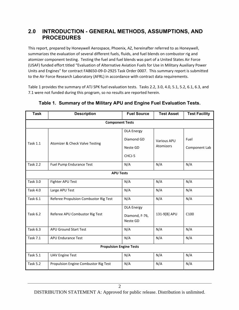
Table 1 provides the summary of ATJ SPK fuel evaluation tests. Tasks 2.2, 3.0, 4.0, 5.1, 5.2, 6.1, 6.3, and
7.1 were not funded during this program, so no results are reported herein.
Table 1. Summary of the Military APU and Engine Fuel Evaluation Tests.
Task Description Fuel Source Test Asset Test Facility
Component Tests
Task 1.1 Atomizer & Check Valve Testing
DLA Energy
Diamond GD
Neste GD
CHCJ-5
Various APU
Atomizers
Fuel
Component Lab
Task 2.2 Fuel Pump Endurance Test N/A N/A N/A
APU Tests
Task 3.0 Fighter APU Test N/A N/A N/A
Task 4.0 Large APU Test N/A N/A N/A
Task 6.1 Referee Propulsion Combustor Rig Test N/A N/A N/A
Task 6.2 Referee APU Combustor Rig Test
DLA Energy
Diamond, F-76,
Neste GD
131-9[B] APU C100
Task 6.3 APU Ground Start Test N/A N/A N/A
Task 7.1 APU Endurance Test N/A N/A N/A
Propulsion Engine Tests
Task 5.1 UAV Engine Test N/A N/A N/A
Task 5.2 Propulsion Engine Combustor Rig Test N/A N/A N/A

3
DISTRIBUTION STATEMENT A: Approved for public release. Distribution is unlimited.
Many military APUs in the USAF inventory do not have commercial equivalents and are not qualified to
Federal Aviation Administration (FAA) Technical Standard Order (TSO) requirements. Approval of new
fuels for these APUs would be based on Honeywell and USAF requirements. However, a number of
military APUs do have commercial equivalents with FAA TSO approval, and commercial requirements for
fuel approval must be considered. Table 2 provides a summary of the Honeywell APUs in the USAF
inventory.
Table 2. Summary of Honeywell APUs in USAF Inventory.
Aircraft Model Designation Honeywell APU
A-10 Thunderbolt 36-50
B-1
B-1A 165-7
B-1B Lancer 165-9
B-2 Spirit 131-3A
C-130 Hercules 85-71A
C-130H Hercules 85-180L
C-130J 85-180L(A)
WC-130 Hercules 85-98
KC/RC/WC-135
KC-135 Stratotanker 85-180L
RC-135U Combat Sent JFS100-135
WC-135 Constant Phoenix 85-98CK
C-17 Globemaster III 331-250[G]
C-20
C-20B 36-100G
C-20H 36-100G
C-22
C-22B 85-98
C-22C 85-98
C-25 660-4
C-32 331-200[E]

4
DISTRIBUTION STATEMENT A: Approved for public release. Distribution is unlimited.
Aircraft Model Designation Honeywell APU
C-37A RE220[GV]
C-38 36-150W
C-40B/C 131-9B
C-5
C-5A 165-1A
C-5B Galaxy 165-1B
C-9A Nightingale 85-98D
E-3 Sentry (AWACS) 165-1
E-4B 660-4
E-8C Joint STARS 331-350[J]
F-15 Eagle JSF190-1
F-22A Raptor G250
F-35 Lightning II G230
H-60 Black Hawk 36-150[BH]
KC-10 Extender 700-4B
T-43A 85-129
VC-25A Air Force One 331-200[P]
2.1 FAA Substantiation Requirements
FAA substantiation requirements for new fuels and additives are detailed in FAA Advisory Circular
AC20-24C. The material outlined in this document is intended for evaluation of fuels and oils new to the
market.
The advisory material requires that the suitability and durability of all new material (fuel or oil) be
established on the basis of experience or test and that the material conform to an approved
specification. ASTM D1655 and MIL-DTL-83133 are listed as examples of historically accepted aviation
fuel specifications. The fuel specifications are identified as operating limitations for fuel.
ASTM D4054 is listed as providing a suitable procedure for evaluating new jet fuels. The laboratory, rig
and engine tests specified in D4054 are noted to be sufficient to fully evaluate the fit for purpose or
suitability of new fuels. The U.S. Department of Defense (DOD) document MIL-HDBK-510-1 was noted
to be similar to the D4054 specification.

5
DISTRIBUTION STATEMENT A: Approved for public release. Distribution is unlimited.
New fuels found to possess performance characteristics and chemical compositions essentially identical
to conventional jet fuel are called drop-in fuels. For fuels considered drop-in jet fuels and where current
operating limitations are adequate to accommodate the fuel (as in D7566 or D1655), then the AC notes
further FAA testing is not required. SAIB NE-11-56 clarifies that fuel produced to D7566 requirements
and released as D1655 fuel is acceptable for use on aircraft and engines certified for operation on D1655
fuels, provided it is re-identified as D1655 fuel.
2.2 ASTM Standard Practice
ASTM D4054 provides laboratory procedures for the qualification and approval of new fuels and fuel
additives for use in commercial and military gas turbine engines. The document provides detailed test
requirements to establish fuel compatibility with other turbine fuels, approved additives, fuel system
components, and aircraft engines. The Original Equipment Manufacturer (OEM) review process and the
process to change the ASTM fuel specification to include a new fuel are also outlined.
2.3 Military Handbook – Aerospace Fuel Certification
The MIL-HDBK-510-1A Aerospace Fuel Certification Handbook documents the USAF process to evaluate
and approve new fuels and fuel additives for Air Force equipment. The document defines the process to
assure a new kerosene type fuel is suitable for aviation, support equipment and vehicles, is
interchangeable with the logistics infrastructure (i.e., a drop-in fuel) and meets USAF standards for
environment, safety and health. Any new fuel is compared to the baseline JP-8 fuel. The USAF approval
process requires each weapon system manager to independently determine if a new fuel is fit for
purpose, and meets operational, performance, durability, safety, and other weapon system
considerations. The handbook also contains an extensive collection of specification and fit for purpose
data for aviation jet fuels.
2.4 Facilities
2.4.1 Combustion Test Facility
The C-100 combustion test facility, located at the Phoenix site, was designed for the full range of
combustor operation from sub-atmospheric (high altitude), cold air and fuel, to high-pressure,
high-temperature test conditions. The central facility air supply and an inline pre-heater/heat exchanger
provide non-vitiated inlet air up to 1,000 °F and 250 psia with airflow rates up to 20 lb/s. Intake air is
filtered to remove atmospheric particulates, pressurized in a central compressor room, and heated with
an indirect fired heater to the desired operating conditions. The combustor rig exhaust is ducted
through an exhaust stack to ambient conditions for performance testing and to a central vacuum system
for altitude ignition or relight testing. Downstream of the combustion system, a computer-controlled
temperature, pressure and emissions rake allows for complete mapping of the combustor exit plane.
The control room houses the required equipment for processing, recording, and displaying analog and
digital test data.

6
DISTRIBUTION STATEMENT A: Approved for public release. Distribution is unlimited.
2.4.2 Atomizer Spray Test Facility
The atomizer bench testing was completed in the fuel component laboratory at the Honeywell facility in
Phoenix, Arizona. Tests were completed in the Malvern test stand which allows various fuels to be
tested at ambient and cold conditions. A heat exchanger is used to chill the fuel to a temperature of
40°C. Fuel temperatures and pressures were measured at the atomizer inlet (as well as throughout the
fuel system) and fuel flow is measured using a Micro Motion mass flow meter upstream of the heat
exchanger.
Spray droplet size is measured with a Malvern Spraytec particle analyzer. The Spraytec determines the
spray droplet size distribution by analyzing the diffraction pattern produced by a laser beam passing
through the spray. The Malvern Spraytec software includes corrections for multiple scattering in high
concentration sprays. Drop size data is presented as SMD, which is a droplet with the same
volume-to-surface area ratio as the entire spray. SMD has been shown to provide a good indication of
atomization quality for correlating gas turbine combustor ignition and lean stability characteristics.
2.5 Instrumentation Requirements
Instrumentation sufficient to demonstrate compliance with the test requirements was included in each
test. Standard engine instrumentation related to fuel type would include engine inlet fuel pressure and
temperature, and fuel flow. For each test, the required special instrumentation to monitor and evaluate
fuel effects on engine performance, operability, or emissions was added. This equipment was certifiable
and traceable by Honeywell Quality and Laboratory Procedural Standards to the National Institute of
Standards and Technology (NIST). Details on instrumentation for any particular test can be found in the
applicable test plan or test report.
2.6 Inspection Requirements
Following the completion of each test, the component, engine, or APU was either disassembled for
inspection by Honeywell engineering, or borescope inspected to check for any distress. In general, there
were no fuel problems reported on any engine or APU related to the 50/50 ATJ blend fuels.
2.7 Emissions Test Equipment
Gaseous and smoke emissions were measured during the 131-9[B] APU combustor rig using averaging
probes, heated sample line, and a mobile emissions truck (Figure 1). Exhaust samples analyzed for
gaseous emissions were measured in accordance with the procedures specified in International Civil
Aviation Organization (ICAO) Annex 16 Appendix 3 and Society of Automotive Engineers (SAE)
ARP1256D. Gaseous emissions were measured with gaseous emission analyzers which were calibrated
prior to and after sampling. Non-Dispersive Infra-Red (NDIR) analyzers were used to measure carbon
dioxide (CO2) and carbon monoxide (CO) emissions. Chemiluminescence type instruments were used to
measure oxides of nitrogen (NOx) emissions. Unburned hydrocarbons (HC) were measured using a
Flame Ionization Detector (FID) and oxygen (O2) paramagnetic type analyzer. Gaseous emissions were
reduced using the procedures from SAE ARP1533B. Optical smoke emissions were measured with a

7
DISTRIBUTION STATEMENT A: Approved for public release. Distribution is unlimited.
Rotadata optical smoke meter and reported as SAE smoke number.
Figure 1. Honeywell Emissions Truck.
2.8 Test Fuels
Rig and component testing were completed with numerous fuels in support of several different
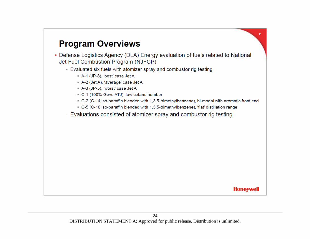
agendas. The DLA Energy evaluation, closely aligned with the NJFCP, evaluated six fuels. Three of those
fuels were petroleum derived and three were experimental fluids or blending components. The two
Green Diesel efforts utilized GDs from both high freeze point and low freeze point type Green Diesels.
The Navy CHCJ-5 evaluation utilized the AFRL contract to obtain atomizer spray data on 100 percent
CHCJ-5. Table 3 summarizes which ATJ SPK feedstocks were used for the various tests. The neat ATJ
evaluated were fully additized by the USAF with Fuel System Icing Inhibitor (FSII), Static Dissipator
Additive (SDA), Corrosion Inhibitor/Lubricity Improver (CI/LI) and Anti-Oxidant (AO) per the MIL-DTL-
83133 specification, prior to shipment to Honeywell.
Table 3. Fuel Use Summary.
Test DLA Energy Green Diesel Navy CHCJ-5
Atomizer Spray Test A-1, A-2, A-3
C-1, C-2, C-5
2% Diamond
30% Neste 100% CHCJ-5
131-9[B] APU
Combustor Rig Test
A-1, A-2, A-3
C-1, C-2, C-5 30% Neste N/A
AFRL supplied the six fuels under evaluation for the DLA Energy program. Detailed information for the
fuels can be found in the individual reports, referenced in Section 0 REFERENCES. In general the
Category A fuels represent the best-case (A-1), nominal (A-2), and the worst-case (A-3) fuels found in

8
DISTRIBUTION STATEMENT A: Approved for public release. Distribution is unlimited.
current use. The A-1 fuel was sought to have low aromatic content, low viscosity, and was desired to be
relatively volatile. This fuel happened to be a JP-8 fuel. The A-2 fuel was average in aromatic content,
viscosity, and volatility, and happened to be a nominal Jet A fuel. The A-3 had higher aromatic content,
higher viscosity, and a relatively low volatility; this fuel was a JP-5 fuel.
The three Category C fluids were meant to probe various physical and chemical characteristics of the
fuels and their influences on combustion parameters. The C-1 fluid is 100 percent Gevo ATJ which has a
low cetane number and composed of primarily two iso-paraffin molecules (C-12 and C-16). The C-2 fluid
was a blend of C-14 iso-paraffin with 1,3,5-trimethylbenzene, which is a bi-modal fluid with an aromatic
front end of distillation. The C-5 fluid was a blend of C-10 iso-paraffin with 1,3,5-trimethylbenzene,
which has a flat distillation range and a high aromatic content. One other unique characteristic of the
C-5 fuel was the relatively low viscosity of the fluid, on the order of 25-30 percent of A-2 viscosity at cold
temperatures.
For the Green Diesel evaluations, the individual fuel producers supplied drums of Green Diesel blending
components, with the help of the Federal Aviation Administration (FAA) and AFRL. The GD fuels were
evaluated in different efforts. At the time of the initial evaluation, the high freeze point GDs from a
Valero refinery (Diamond GD, DGD) and a Solazyme refinery (F-76) were blended at low blend ratios (2
to 5 percent) with Honeywell Jet A. Later evaluations, a low freeze point GD from Neste was blended at
30 percent with Honeywell JP-8.
For the CHCJ-5 atomizer spray evaluations, the US Navy supplied the 100 percent CHCJ-5 which was
produced by Applied Research Associates (ARA) – Chevron. The CHCJ-5 was evaluated as received from
the Navy.
All testing was conducted at the Phoenix site, where the standard laboratory Jet A or JP-8 was used for
baseline testing and blending. When changing fuels, the cell fuel systems were purged and flushed with
the next fuel to be tested. Prior to testing, a fuel sample was obtained at the rig or component inlet and
analyzed for specific gravity to ensure the fuel system was purged, the correct fuel was being used, and
to obtain the fuel properties needed to conduct the test. At the completion of the testing with each
fuel, another sample was obtained for more extensive fuel analysis.
The data from tests with Jet A and JP-8 fuel formed the baseline for comparison with the GD blends.
The data from tests with JP-5 (DLA Energy A-3) formed the baseline for comparison with the 100 percent
CHCJ-5 fuel. Key fuel properties for the individual fuel evaluations are found in respective reports,
Appendix 2 and Appendix 3 for the GD blends and 21-15778 for the CHCJ-5 fuel.
2.9 Fuel Analysis
Samples were obtained from the fuel tanks, drums, or at the test rig inlet and analyzed to confirm the
specification fuel properties. Pretest samples were analyzed to verify the correct test fuel was being
used and the test cell had been thoroughly purged of the previous fuel, and to provide fuel properties
needed to run the test. Posttest fuel samples were analyzed in more detail, to verify critical fuel
properties and fuel quality. Fuel samples were taken in standard laboratory polyethylene sample
bottles.

9
DISTRIBUTION STATEMENT A: Approved for public release. Distribution is unlimited.
3.0 ATOMIZER AND CHECK VALVE BENCH TESTING (TASK 1.1)
APUs used in military transport and tanker service are similar to those used in commercial transport
aircraft. These APUs are typically operated to provide a power source for the aircraft air conditioning
units and electrical systems on the ground, and for main engine starting. These APUs are also used
in-flight as an alternate electrical power source in the event of a main engine system failure. APU start
times are typically 30-60 seconds, though more rapid starts are required for some applications. In-flight
starting of APUs can be challenging, especially at higher altitudes or after a long flight that cold soaks
both the APU and fuel.
APUs used in fighters and bombers, such as the JFS190 (F-15), 36-200 (F-18), 85-series (C-130J), 165-9
(B-1B), G250 (F-22), G230 (JSF), and 131-3[A] (B-2), are very different from commercial APUs. These
units typically have very rapid start requirements and are used to start the main engines on the ground,
for emergency main engine starting, or to recover aircraft control in-flight. To achieve these rapid
starts, properly atomized fuel must be delivered to the combustion chamber and ignited before the APU
accelerates through the combustor ignition window.
Proper atomizer performance is a critical aspect to reliable cold and altitude starting for both transport
and fighter APUs. Pressure atomizers, which are sensitive to fuel properties, are used in most military
APUs to ensure adequate atomization over the flight envelope. Several fuels were evaluated with
atomizer spray bench testing at ambient and cold conditions to assess their impact on APU atomizer
performance.
3.1 Test Fuels
Over the course of three separate efforts, eleven fluids were used for spray characterization testing
which included standard calibrating fluid (MIL-PRF-7024 Type II), Viscor 12 cSt fluid, the six DLA Energy
fuels (A-1, A-2, A-3, C-1, C-2, and C-5), 100 percent CHCJ-5, and two Green Diesel blends (2 percent DGD
and 30 percent Neste GD).
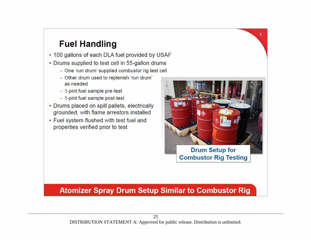
The 7024 calibrating fluid and the Viscor 12 cSt fluid were supplied from the test facility in 30-gallon
storage reservoirs. The test fuels and fuel blends were supplied to the Malvern test stand in 55-gallon
barrels. The DLA Energy fuels and the 100 percent CHCJ-5 fuels were evaluated as delivered to
Honeywell; these fuels were evaluated neat or were pre-blended, so no blending was required. The GD
blends were prepared using 55-gallon drums. For the 2 percent DGD blend, approximately 1 gallon of
neat Diamond GD was added to an empty, clean, and dry 55-gallon barrel. A graduated aluminum
measuring stick was used to gauge the height of the fuel in the drum (~0.75 inch), 49 gallons of Jet A was
then added to the drum order to achieve a 2/98 mixture of DGD and Jet A. The 30 percent Neste GD
blend was created similarly but with 15 gallons of the neat Neste GD (~10 in) with 35 gallons of JP-8
(~24 in). Prior to blending the Neste GD with JP-8 rather than Jet A, OEM consensus was sought and
achieved. Prior to obtaining spray data, fuel properties for each fluid under test were verified by the
Honeywell Chemistry Laboratory. Detailed fuel properties can be found in their respective test reports,
but a summary of fuel properties can be found in Table 4.

10
DISTRIBUTION STATEMENT A: Approved for public release. Distribution is unlimited.
Table 4. Atomization Test Fuel Properties.
Fluid Specific Gravity Freeze Point
°C
Viscosity
at 25°C, cSt
Viscosity
at -40°C, cSt
DLA A-1 0.781 -50 1.40 6.6
DLA A-2 0.803 -49 1.65 9.3
DLA A-3 0.827 -59 2.00 13.4
DLA C-1 0.762 <-80 1.92 10.2
DLA C-2 0.782 -45 1.75 10.6
DLA C-5 0.773 -80 0.95 2.9
100% CHCJ-5 0.803 -52 1.67 9.1
2% DGD 0.817 -41 1.81 11.2
30% Neste GD 0.781 -44 1.90 12.0
3.2 Atomizer Spray Bench Testing
Honeywell completed fuel atomizer bench testing of ambient and cold fuels and fuel blends. Atomizer
performance parameters, including flow and spray characteristics, were measured over a range of
typical APU engine start and operating conditions. Test results show that both the ambient and cold
atomization characteristics of the fuels and fuel blends are very similar to the petroleum-derived
baselines and appear to be driven by fluid viscosity.
3.2.1 Fuel Atomizer Configuration
Pressure type fuel atomizers are used in most APUs to ensure reliable starting and operation up to
maximum start altitude after an extended cold soak. Depending on the particular evaluation, either two
or three representative pressure-type fuel atomizers were selected for testing. For the DLA Energy
evaluation, a small flow number (FN) atomizer and a large FN atomizer were evaluated. For the
100 percent CHCJ-5 and Green Diesel evaluations, a medium FN atomizer was added to the small and
large FN atomizer evaluations.
Atomizer FN (Equation 1) is an indication of the size of the atomizer and is relatively constant for
different operating conditions.
FN = Wf / Pf 0.5 [1]
Where:
Wf = fuel flow, pph (lb/h)
Pf = differential fuel pressure, psid

11
DISTRIBUTION STATEMENT A: Approved for public release. Distribution is unlimited.
Droplet size, or Sauter Mean Diameter (SMD), is an indication of atomizer performance. The SMD
indicates the size of the droplets in the spray generated by the atomizer, thus providing a relative
indication of atomizer performance when comparing results from the test fluids. Fluid properties and
atomizer operating conditions can affect SMD by the general expression (Lefebvre, Gas Turbine
Combustion, 1983) of:
SMD = (K*(**SG)0.25*Wf0.25)/(air
0.25Pf0.5) [2]
Where:
K = constant
= fuel surface tension, dynes/cm
= fuel viscosity, cSt
SG = fuel specific gravity
air = air density, lb/ft3
For additional detail on the atomizer hardware used to evaluate the fuels and fuel blends, Honeywell
Documents 21-15778 and 21-15991 detail the hardware and fuels under test.
3.2.2 Test Facility
All of the atomizer bench testing was completed in the fuel component laboratory at the Honeywell
facility in Phoenix, Arizona. Tests were completed in the Malvern test stand which allows various fuels
to be tested at ambient and cold conditions. A schematic of the test setup is shown in Figure 2 and a
photograph of the facility is shown in Figure 3.
Needle valves were employed to either bypass or route fuel through a heat exchanger when testing
ambient or cold fuel. The heat exchanger was used to chill the fuel to a temperature of -40°C.
Duratherm Heat Transfer Fluid was circulated through a counter-flow heat exchanger setup with the
test fuel. The Duratherm fluid was chilled by flowing through a methanol containing cold cart. The cold
cart was chilled by a liquid nitrogen (LN2) coil used to continuously maintain the methanol bath
temperature with precise control. This setup was new for the spray lab and was a vast improvement on
previous fuel chilling techniques. The counter-flowing Duratherm strategy allowed for precise
temperature control of the test fluids without over-chilling the fluid. Over chilling has previously been
used to ensure -40°F fuel temperatures at the atomizer exit and is not desirable, as it has the potential
to cause wax crystals in the fuel and impact the atomization results.
Fuel temperatures and pressures were measured at the atomizer inlet (as well as throughout the fuel
system) and fuel flow was measured using a Micro Motion mass flow meter upstream of the heat
exchanger.
Spray droplet size was measured with a Malvern Spraytec particle analyzer. The Spraytec determines
the spray droplet size distribution by analyzing the diffraction pattern produced by a laser beam passing
through the spray. The Malvern Spraytec software includes corrections for multiple scattering in high
concentration sprays. Drop size data is presented as SMD, which is a droplet with the same volume-to-

12
DISTRIBUTION STATEMENT A: Approved for public release. Distribution is unlimited.
surface area ratio as the entire spray. SMD has been shown to provide a good indication of atomization
quality for correlating gas turbine combustor ignition and lean stability characteristics.
Figure 2. Malvern Test Stand Schematic.
Figure 3. Updated Malvern Test Stand.
Spraytec Transmitter
Spraytec Receiver
Fuel Spray and Laser
Heat Exchanger
Tubing

13
DISTRIBUTION STATEMENT A: Approved for public release. Distribution is unlimited.
3.2.3 Test Conditions
Each atomizer was tested over a range of conditions representative of APU operation. For pressure
atomizers, this requires a range of inlet fuel pressures. Measurements were taken with the fuels and
atomizers at room temperature and at -40°F (-40°C) to simulate cold operation. For the Viscor
calibration fluid only, the fluid temperature was controlled to achieve a 12 cSt viscosity during
evaluation. Prior to testing, the Viscor fluid was sampled and analyzed for its 12 cSt temperature. That
temperature (77°F or 74°F depending on batch) was maintained throughout testing to provide 12 cSt
viscosity fluid to the atomizers under evaluation.
3.2.4 Test Results
The atomization and spray characteristics using the DLA Energy fuels, the Green Diesel fuel blends, and
the 100 percent CHCJ-5 are detailed in their individual Honeywell Documents, 21-15991, Appendix 2 and
Appendix 3, and 21-15778, respectively. Overall, warm fuels and fuel blends appear to behave similarly.
However, at cold fuel (-40°C) conditions, the fuels and fuel blend droplet sizes and spray angles are
predominantly driven by the fluid viscosity, with larger droplets and narrow spray angles occurring with
higher viscosity fluids.
3.3 Summary
Atomizer spray performance at ambient and cold conditions was shown to not significantly degrade with
use of the DLA Energy Category C fuels, the Green Diesel blends, nor the 100 percent CHCJ-5 fuel. Some
fuels resulted atomizer performance decreasing at low pressures under cold fuel conditions due to
viscosity near the 12 cSt limit at the -40°C test temperature. Fuel low temperature operating limits are
typically set to a maximum viscosity of 12 cSt to ensure reliable APU cold starting.
Data for all fluids tested showed that increasing fuel pressure improves atomizer performance, thus
generating smaller drop sizes and wider spray angles. This trend is due to the increase in pressure
forces that overcome the fluid surface tension and viscosity. Cold sprays generated larger drop sizes
due to the higher surface tension and viscosity occurring at low fuel temperatures.

14
DISTRIBUTION STATEMENT A: Approved for public release. Distribution is unlimited.
4.0 131-9 COMBUSTOR RIG TESTS (TASK 6.2)
The 131-9 APU combustor rig evaluated combustor performance, lean stability and ignition performance
of all six DLA Energy fuels and a 30 percent Neste Green Diesel blend with 70 percent petroleum-derived
JP-8. There were no significant effects on combustor performance including thermodynamic pattern
factor (PF) and radial profile due to fuel type. There were no significant differences in lean blowout
fuel-air ratios or lean ignition fuel-air ratios for the Neste GD fuel blend evaluation, though some of the
DLA Energy fuels did vary in operability results.
4.1 Introduction and Test Summary
The 131-9[B] combustor rig tests were conducted by Honeywell Aerospace, Phoenix, Arizona, supporting
multiple efforts the contract, “Evaluation of Alternative Fuels for Use in Military Auxiliary Power Units
and Engines Program” funded by USAF/AFRL Contract No. FA8650-09-D-2925 Task Order 0007.
4.1.1 General Information
Figure 4 shows a photograph of the combustor rig installed in the C-100 test cell. The rig is operated at
full-engine conditions and is designed to duplicate the 131-9[B] engine combustion system
aerodynamics from the deswirl exit to the turbine stator inlet plane. Engine components include the
axial deswirl, combustor, outer transition liner, fuel atomizers, fuel manifolds, igniter plugs, ignition
exciter, and inner transition liner.
The standard 131-9 ignition system, consisting of an igniter exciter and igniter was used. The igniter is
located at roughly the 8 o’clock position, viewed from aft, looking forward. A dummy igniter position for
instrumentation purposes is located near bottom dead center.
Figure 4. 131-9 Combustor Rig Installed in C-100 Test Cell.
4.1.2 Combustion System Hardware
The 131-9 combustor rig was used for multiple development tests in between DLA Energy and Neste GD
blend evaluations. It was necessary to disassemble the rig in order to reassemble it as a 131-9[B]

15
DISTRIBUTION STATEMENT A: Approved for public release. Distribution is unlimited.
configuration for each fuel evaluation. The aero hardware that was utilized for this testing included the
deswirl, combustor, containment ring, and the combustor case.
4.1.3 Fuel System
The 131-9[B] production fuel system, which consists of the fuel flow-divider and fuel atomizers, was
used for this rig test. Fuel atomizers were flow tested prior to rig testing and after the test was
completed. The multiple rig builds were required to complete the multiple test series, the atomizers
were installed in the same locations and are documented in their respective test reports, which can be
found in Honeywell Document 21-15989, Appendix 2 and Appendix 3.
4.1.4 Test Objectives
The overall goal of the DLA Energy combustor rig test was to probe various chemical and physical fuel
properties and their impact on combustor performance and operability. For the Neste GD blend
evaluation, the intent of the test was to determine if the 30 percent Neste GD blend resulted in any
adverse effects on the 131-9 combustion system.
4.2 Hardware and Rig Inspections
4.2.1 Rig and Relevant Hardware
Standard pretest procedures were followed in order to ensure test hardware was ready for test and met
specifications. Hardware was checked to make sure that the part and serial numbers were correct.
Basic functionality checks were performed during assembly, such as verifying that the rotating drum
turned freely and the igniter box was working properly.
4.2.2 Instrumentation Check
Instrumentation was also checked for basic functionality, which included thermocouple (TC) resistance
to ground checks. All leads were securely tacked down with the proper identification names. Upon
arriving at the test cell, a final instrumentation inspection was completed during the rig installation
ensuring the test setup was complete.
4.2.3 Standard Instrumentation
Standard cell instrumentation was used during this test to monitor the usual rig test parameters such as
inlet and exit conditions of airflow, temperature, pressure, and fuel flow.
4.2.4 Data Acquisition
Digital data acquisition recorded all measured parameters. Temperature and pressure traverses of the
combustor exit gas path were performed with a rotating drum bearing a pressure rake and a
temperature rake to cover the entire exit annulus. The fast-scan method was employed for all cases
using both forward and reverse traverses in order to ensure repeatable data.

16
DISTRIBUTION STATEMENT A: Approved for public release. Distribution is unlimited.
4.2.5 Test Fuels
Over the course of two separate efforts, nine fuels were evaluated on the 131-9 APU combustor rig
which included the six DLA Energy fuels (A-1, A-2, A-3, C-1, C-2, and C-5) as well as the 30 percent Neste
GD blend Jet A and JP-8 baselines.
The test fuels and fuel blends were supplied to the C-100 combustor test cell in 55-gallon barrels. The
DLA Energy fuels were evaluated as delivered to Honeywell; these fuels were evaluated neat or were
pre-blended, so no blending at Honeywell was required. The 30 percent Neste GD blend was prepared
using 55-gallon drums. The 30 percent Neste GD blend was created by filling an empty, clean, and dry
55-gallon drum with 15 gallons of the neat Neste GD. A graduated aluminum measuring stick was used
to gauge the height of the fuel in the drum (~10 in). The drum was then filled with 35 gallons of JP-8
(~24 in). Prior to collecting rig test data, fuel properties for each fluid under test were verified by the
Honeywell Chemistry Laboratory. Detailed fuel properties can be found in their respective test reports,
but a summary of fuel properties from the combustor rig tests can be found in Table 5.
4.2.6 Fuel Sample Analysis
Before testing with each fuel, the test cell fuel system was flushed with the new test fuel. Fuel samples
were obtained at the beginning and the end of the rig tests. Samples were analyzed confirming the fuel
system was thoroughly flushed.
Table 5. Combustor Rig Test Fuel Properties.
Fluid Specific Gravity LHV
MJ/kg
Freeze Point
°C
Viscosity
at 25°C, cSt
Aromatics
%t
DLA A-1 0.781 43.5 -50 1.40 10.0
DLA A-2 0.804 43.2 -49 1.65 15.0
DLA A-3 0.827 43.1 -50 2.01 15.0
DLA C-1 0.761 44.0 < -80 1.93 1.0
DLA C-2 0.782 43.5 -45 1.75 14.5
DLA C-5 0.772 43.3 -58 0.93 26.0
30% Neste GD 0.780 43.7 -44 1.89 7.0
4.3 Test Results
Test results are detailed in the individual reports found in 21-15989 and Appendix 3. DLA Energy
combustor rig test results illustrated that viscosity appeared to play a primary role in both ignition and
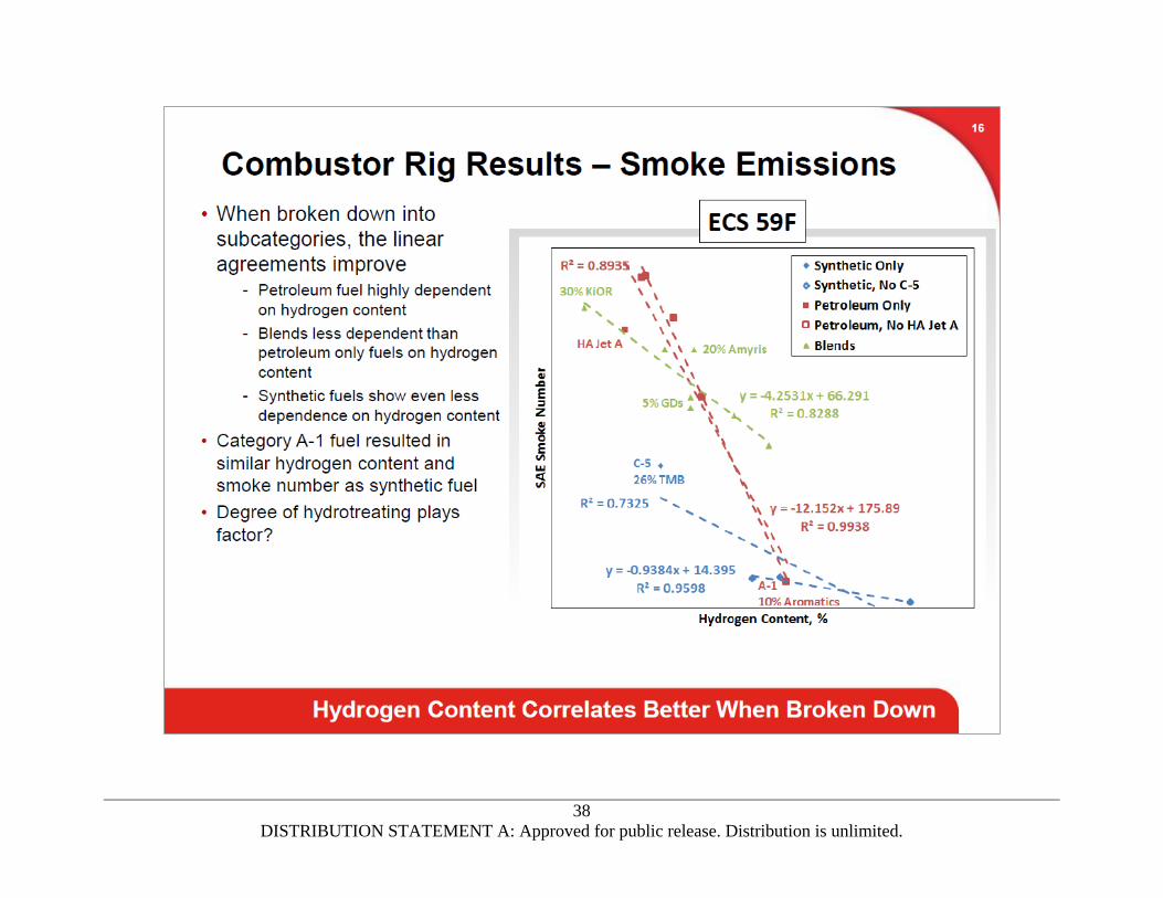
lean blowout results. Smoke emissions appeared to have additional drivers other than aromatic content
or hydrogen-to-carbon ratio. Combustor performance parameters like pattern factor, radial profile, and
gaseous emissions appeared to be rather insensitive to the various fuel properties.

17
DISTRIBUTION STATEMENT A: Approved for public release. Distribution is unlimited.
As for the 30 percent Neste GD blend evaluation, the GD blend performed similarly to the Jet A and JP-8
baseline fuels with respect the combustor performance (pattern factor and radial profile), gaseous, and
smoke emissions as well as cold and altitude ignition. However, there were a few lean blowout
conditions that the 30 percent-Neste GD blend performed worse than the baseline Jet A fuel.
4.4 Conclusions
For the DLA Energy evaluation, six fuels with varying physical and chemical properties were evaluated to
determine their impact on 131-9[B] APU combustion system performance, gaseous and smoke
emissions, operability (LBO), and ignition characteristics. Combustion performance measurement
results indicated that all fuels were acceptable and showed no adverse effects on combustion system
performance (pattern factor and radial profile). The fuels did produce different smoke emissions which
were largely correlated to the fuel hydrogen content. Gaseous emissions were similar with all fuels.
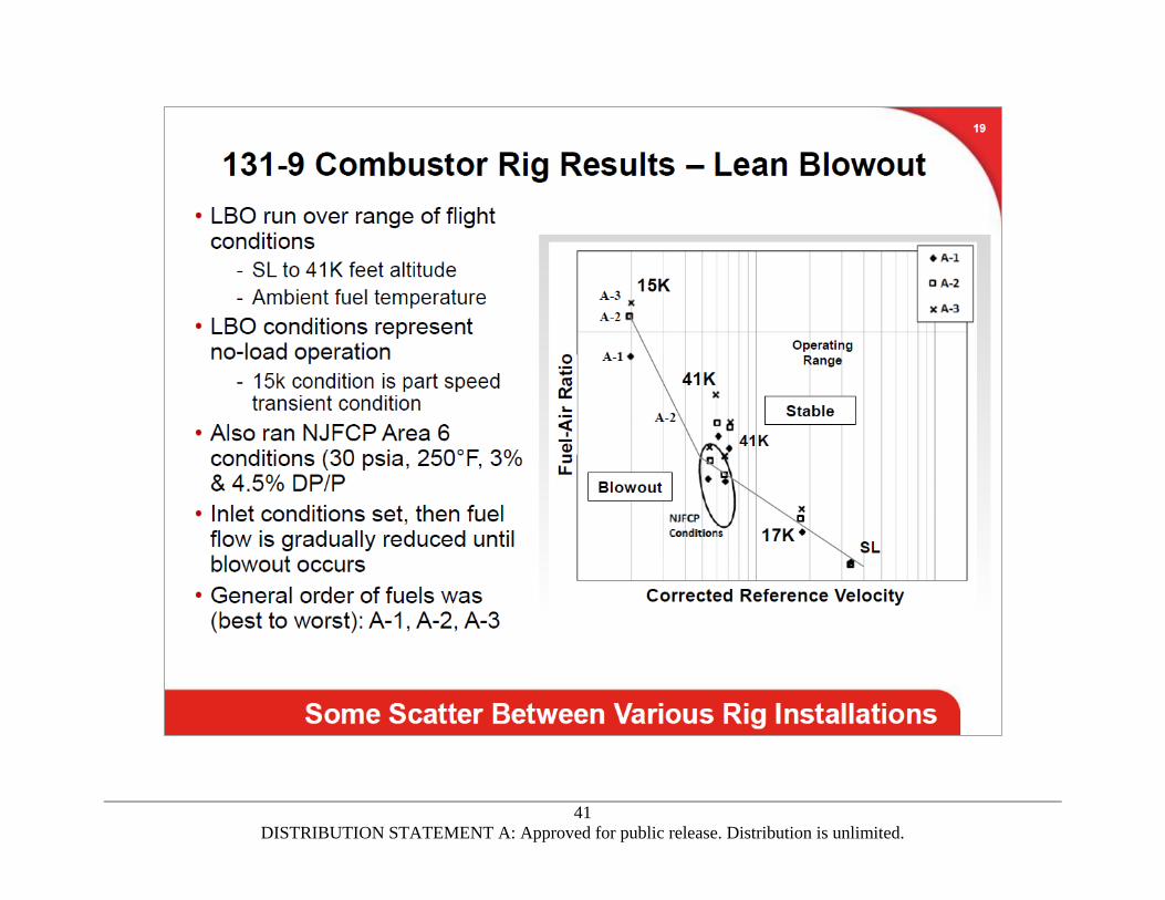
Ignition and LBO characteristics appeared to be primarily based on the fuel viscosities with the lowest
viscosities resulting in the lowest LBO and ignition FARs.
For the Neste GD evaluation, combustor rig test results showed there was no adverse effect of a
30 percent blend of low freeze point GD SPK and conventional petroleum derived jet fuel on combustion
performance (pattern factor and profile), ignition characteristics, and exhaust gaseous emissions, with a
significant reduction in exhaust smoke emissions. However, a few lean blowout conditions resulted in
higher blowout FARs when compared to the baseline Jet A fuel.

18
DISTRIBUTION STATEMENT A: Approved for public release. Distribution is unlimited.
5.0 CONCLUSIONS AND RECOMMENDATIONS
This report, prepared by Honeywell Aerospace (Phoenix, Arizona), summarizes testing and analysis of
multiple fuel evaluation efforts. Fuel evaluations for DLA Energy, multiple Green Diesel evaluations, and
a 100 percent CHCJ-5 fuel effort supporting a Navy fuel evaluation were all part of the USAF contract
FA8650-09-D-2925 Task Order 0007. As part of the USAF contract, Honeywell conducted atomizer spray
tests and 131-9 APU combustor rig tests using several fuels and fuel blends.
Atomization spray characteristics were evaluated using multiple fuels and fuel blends. The droplet sizes
and spray angles appeared to be attributed to fuel viscosities; with the higher the fuel viscosity resulting
in the larger droplets. The greatest differences were observed in smaller atomizers where viscosity
effects were pronounced. There were no adverse effects on atomizer performance with the GD blends.
Atomizer spray performance at ambient and cold conditions was shown to not significantly degrade with
use of the GD blends. This difference in droplet size was well correlated to the fluid viscosities.
The DLA Energy fuels and a Neste GD fuel blend were used with a 131-9 APU combustor rig test in order
to evaluate their impact to combustor performance, operability, and ignition characteristics. The
performance (pattern factor and radial profile) of all fuels were similar. For the DLA Energy evaluation,
combustor operability appeared to be impacted by the fuel viscosities. Results from the 30 percent
Neste GD blend were compared to results with a baseline Jet A and baseline JP-8 fuel and results
indicated that the Neste blend was similar at most conditions but appeared to be worse than the
baseline Jet A fuel for multiple LBO conditions.

19
DISTRIBUTION STATEMENT A: Approved for public release. Distribution is unlimited.
REFERENCES
Document Number Title
FAA Advisory Circular
AC20-24C Approval of Propulsion Fuels and Lubricating Oils
SAE and ASTM Documents
ASTM D1655 Standard Specification for Aviation Turbine Fuels
ASTM D4054 Standard Practice for Qualification and Approval of New Aviation Fuels and Fuel Additives
ASTM D7566 Standard Specification for Aviation Turbine Fuel Containing Synthesized Hydrocarbons
SAE ARP1179D
SAE ARP1256D
SAE ARP1533B
Aircraft Gas Turbine Engine Exhaust Smoke Measurement
Procedure for the Continuous sampling and Measurement of Gaseous
Emissions from Aircraft Turbine Engines
Procedure for the Analysis and Evaluation of Gaseous Emissions from
Aircraft Engines
Military Documents
MIL-DTL-5624 Turbine Fuel, Aviation, Grades JP-4 and JP-5
MIL-DTL-83133 Turbine Fuels, Aviation, Kerosene Types, NATO F-34 (JP-8), NATO F-35, and JP-8+100
MIL-HDBK-510-1
MIL-PRF-7024
MIL-PRF-7808
MIL-STD-45662
Aerospace Fuel Certification
Calibrating Fluids, Aircraft Fuel System Components
Lubricating Oil, Aircraft Turbine Engine, Synthetic Base
Calibration System Requirements
Misc. Documents
ICAO Annex 16
Volume II Aircraft Engine Emissions
Honeywell Documents
21-14520 Summary of USAF Evaluation of Fischer-Tropsch Jet Fuel for Use in Military Auxiliary Power Units and Military Engines
21-15351B Evaluation of Hydroprocessed Esters and Fatty Acids (HEFA) for Use in Military Auxiliary Power Units and Engines
21-15516 Evaluation of Alternative Fuels for Use in Military Auxiliary Power Units and Engines

20
DISTRIBUTION STATEMENT A: Approved for public release. Distribution is unlimited.
Document Number Title
21-15778 Navy Aircraft Biofuels Program Atomizer Spray Bench Test Results Using 100 Percent CHCJ-5 Fuel
21-15989 Test Report: DLA Fuel Evaluation in the 131-9 APU Combustor Rig
21-15990 Test Report: DLA Fuel Evaluation in the 131-9 APU Combustor Rig – Unlimited Rights
21-15991 DLA Energy Atomizer Spray Bench Test Report Using Alternative Fuels
21-15992 DLA Energy Atomizer Spray Bench Test Report Using Alternative Fuels – Unlimited Rights
Appendix 1 Defense Logistics Agency (DLA) Energy Fuel Evaluations: Presentation of Atomizer Spray and Combustor Rig Testing
Appendix 2 Honeywell Rig and Engine Tests Using Green Diesel Fuel Blends
Appendix 3 Honeywell Tests to Evaluate a Low Freeze Point Green Diesel Fuel Blend

21
DISTRIBUTION STATEMENT A: Approved for public release. Distribution is unlimited.
APPENDIX 1. DEFENSE LOGISTICS AGENCY (DLA) ENERGY FUEL
EVALUATIONS: PRESENTATION OF ATOMIZER SPRAY AND
COMBUSTOR RIG TESTING
(37 pages)

22
DISTRIBUTION STATEMENT A: Approved for public release. Distribution is unlimited.
23
DISTRIBUTION STATEMENT A: Approved for public release. Distribution is unlimited.
24
DISTRIBUTION STATEMENT A: Approved for public release. Distribution is unlimited.
25
DISTRIBUTION STATEMENT A: Approved for public release. Distribution is unlimited.

26
DISTRIBUTION STATEMENT A: Approved for public release. Distribution is unlimited.

27
DISTRIBUTION STATEMENT A: Approved for public release. Distribution is unlimited.

28
DISTRIBUTION STATEMENT A: Approved for public release. Distribution is unlimited.

29
DISTRIBUTION STATEMENT A: Approved for public release. Distribution is unlimited.

30
DISTRIBUTION STATEMENT A: Approved for public release. Distribution is unlimited.

31
DISTRIBUTION STATEMENT A: Approved for public release. Distribution is unlimited.

32
DISTRIBUTION STATEMENT A: Approved for public release. Distribution is unlimited.

33
DISTRIBUTION STATEMENT A: Approved for public release. Distribution is unlimited.

34
DISTRIBUTION STATEMENT A: Approved for public release. Distribution is unlimited.

35
DISTRIBUTION STATEMENT A: Approved for public release. Distribution is unlimited.

36
DISTRIBUTION STATEMENT A: Approved for public release. Distribution is unlimited.

37
DISTRIBUTION STATEMENT A: Approved for public release. Distribution is unlimited.
38
DISTRIBUTION STATEMENT A: Approved for public release. Distribution is unlimited.

39
DISTRIBUTION STATEMENT A: Approved for public release. Distribution is unlimited.

40
DISTRIBUTION STATEMENT A: Approved for public release. Distribution is unlimited.
41
DISTRIBUTION STATEMENT A: Approved for public release. Distribution is unlimited.

42
DISTRIBUTION STATEMENT A: Approved for public release. Distribution is unlimited.

43
DISTRIBUTION STATEMENT A: Approved for public release. Distribution is unlimited.

44
DISTRIBUTION STATEMENT A: Approved for public release. Distribution is unlimited.

45
DISTRIBUTION STATEMENT A: Approved for public release. Distribution is unlimited.

46
DISTRIBUTION STATEMENT A: Approved for public release. Distribution is unlimited.

47
DISTRIBUTION STATEMENT A: Approved for public release. Distribution is unlimited.
48
DISTRIBUTION STATEMENT A: Approved for public release. Distribution is unlimited.

49
DISTRIBUTION STATEMENT A: Approved for public release. Distribution is unlimited.

50
DISTRIBUTION STATEMENT A: Approved for public release. Distribution is unlimited.

51
DISTRIBUTION STATEMENT A: Approved for public release. Distribution is unlimited.

52
DISTRIBUTION STATEMENT A: Approved for public release. Distribution is unlimited.

53
DISTRIBUTION STATEMENT A: Approved for public release. Distribution is unlimited.

54
DISTRIBUTION STATEMENT A: Approved for public release. Distribution is unlimited.
55
DISTRIBUTION STATEMENT A: Approved for public release. Distribution is unlimited.

56
DISTRIBUTION STATEMENT A: Approved for public release. Distribution is unlimited.
57
DISTRIBUTION STATEMENT A: Approved for public release. Distribution is unlimited.

58
DISTRIBUTION STATEMENT A: Approved for public release. Distribution is unlimited.

59
DISTRIBUTION STATEMENT A: Approved for public release. Distribution is unlimited.
APPENDIX 2. HONEYWELL RIG AND ENGINE TESTS
USING GREEN DIESEL FUEL BLENDS
(16 pages)

60
DISTRIBUTION STATEMENT A: Approved for public release. Distribution is unlimited.
Honeywell Rig and Engine Tests of Green Diesel Fuel Blends
Rig and engine testing of high freeze point hydroprocessed esters and fatty acids (HEFA) fuel blends, also
called Green Diesel (GD) blends, was completed at the Honeywell Aerospace facility in Phoenix, Arizona.
Funding for the testing was provided by the Federal Aviation Administration (FAA) and the Volpe
National Transportation Systems Center under the Office of the Secretary of Transportation, FAA
Continuous Lower Energy Emissions and Noise (CLEEN) I, and DLA Energy/Air Force Research Laboratory
(AFRL). All findings and conclusions expressed are those of the authors (Honeywell) and do not
necessarily reflect the views of the contracting agencies.
The purpose of the testing was to evaluate the effect of GD fuel blends on the performance, operability,
and emissions of aircraft gas turbine engines. Blends from two different high freeze point HEFA
synthetic paraffinic kerosene (SPK) blending components with conventional Jet A petroleum derived fuel
were evaluated.
The following evaluation tests were completed using the two GD fuel blends:
131-9 auxiliary power unit (APU) combustor rig performance, emissions, lean blowout (LBO), and
cold and altitude ignition tests
Fuel atomizer cold plugging test
Fuel atomizer cold spray test
131-9 APU cold and altitude starting test
Green Diesel Blending Components
The neat Diamond Green Diesel (DGD) SPK was provided by Valero’s Diamond Green Diesel facility in
Louisiana and produced from recycled animal fat and used cooking oil. The neat F-76 GD SPK provided
by the U.S. Navy (HRD-76) was produced by a toll facility to MIL-DTL-16884 (Naval Distillate)
requirements for Solazyme. Two 55-gallon drums of each GD SPK was provided. Selected properties of
the neat GD SPKs are shown in Table 1. The GD SPK blending component freeze point (cloud point),
distillation end point, and density were above the current HEFA SPK limits (D7566-16). However, if
blended into Jet A fuel in a low enough concentration (depending on properties of the GD and
petroleum derived fuel blending components) the final fuel blend could meet D7566 Table 1
requirements. Fuel for each test series was blended just prior to the test, so there were some test-to-
test variations in both the Jet A and blend properties.
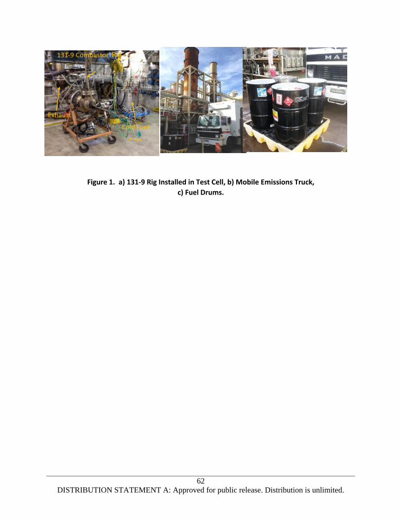
131-9 Combustor Rig Testing
131-9 combustor rig testing was completed to determine the effect of the GD fuel blends on combustion
system performance. A full-scale 131-9 combustor rig was installed in the combustion test facility
(Figure 1) in Phoenix, Arizona with ignition and blowout tests completed in July 2014 and performance
and emissions tests in November 2015.

61
DISTRIBUTION STATEMENT A: Approved for public release. Distribution is unlimited.
The GD SPKs were blended 5 percent by volume with Honeywell Jet A (D1655) for combustor rig testing
at customer request. The test fuels for combustor rig testing consisted of a Jet A baseline, a 5 percent
blend of DGD and Jet A, and a 5 percent blend of Navy F-76 GD and
Jet A.
Table 1. Green Diesel SPK Properties.
Fuel Property 100% DGD 100% F-76 GD
Specific Gravity (D1298) 0.780 0.780
Temp, °C for 12 cSt viscosity (1) -14 -13
Viscosity, cSt at +25°C (D445) 3.7 3.8
Dist IBP, °C (D86) 148 184
10% Dist Temp, °C (D86) 226 234
20% Dist Temp, °C (D86) 253 260
50% Dist Temp, °C (D86) 280 277
90% Dist Temp, °C (D86) 293 290
Dist FBP, °C (D86) 312 308
LHV, MJ/kg (D240) 43.92 43.99
Smoke Point, mm (D1322) 49.5 >50
Aromatics, %v (D1319) 0.0 0.0
Cloud Point, °C (D2500) -4 -8
Water, ppmw (E1064) 25 31
(1) Calculated
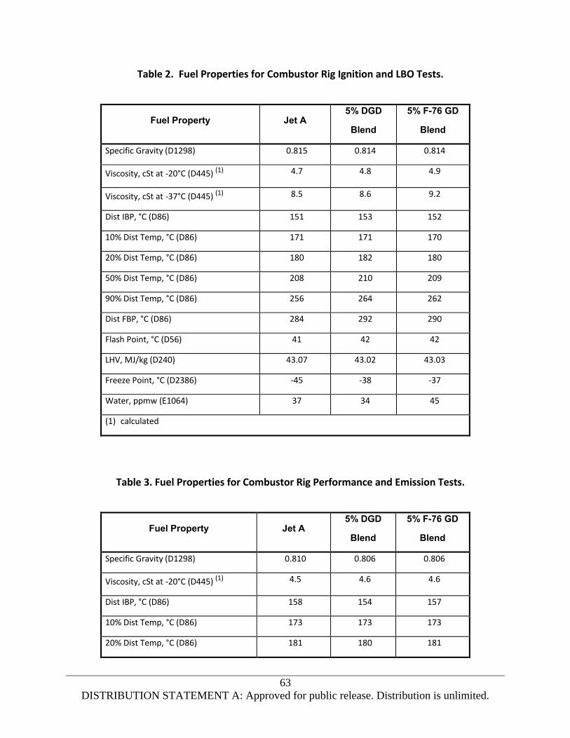
The 5 percent GD blends were supplied to the test cell from 55-gallon drums, while the Jet A was
provided from the standard laboratory fuel supply. Table 2 provides properties of the Jet A and GD
blends used for combustor rig ignition and LBO testing, while Table 3 provides properties used for
combustor rig performance and emissions testing.
62
DISTRIBUTION STATEMENT A: Approved for public release. Distribution is unlimited.
Figure 1. a) 131-9 Rig Installed in Test Cell, b) Mobile Emissions Truck,
c) Fuel Drums.
131-9 Combustor Rig
Exhaust
63
DISTRIBUTION STATEMENT A: Approved for public release. Distribution is unlimited.
Table 2. Fuel Properties for Combustor Rig Ignition and LBO Tests.
Fuel Property Jet A 5% DGD
Blend
5% F-76 GD
Blend
Specific Gravity (D1298) 0.815 0.814 0.814
Viscosity, cSt at -20°C (D445) (1) 4.7 4.8 4.9
Viscosity, cSt at -37°C (D445) (1) 8.5 8.6 9.2
Dist IBP, °C (D86) 151 153 152
10% Dist Temp, °C (D86) 171 171 170
20% Dist Temp, °C (D86) 180 182 180
50% Dist Temp, °C (D86) 208 210 209
90% Dist Temp, °C (D86) 256 264 262
Dist FBP, °C (D86) 284 292 290
Flash Point, °C (D56) 41 42 42
LHV, MJ/kg (D240) 43.07 43.02 43.03
Freeze Point, °C (D2386) -45 -38 -37
Water, ppmw (E1064) 37 34 45
(1) calculated
Table 3. Fuel Properties for Combustor Rig Performance and Emission Tests.
Fuel Property Jet A 5% DGD
Blend
5% F-76 GD
Blend
Specific Gravity (D1298) 0.810 0.806 0.806
Viscosity, cSt at -20°C (D445) (1) 4.5 4.6 4.6
Dist IBP, °C (D86) 158 154 157
10% Dist Temp, °C (D86) 173 173 173
20% Dist Temp, °C (D86) 181 180 181

64
DISTRIBUTION STATEMENT A: Approved for public release. Distribution is unlimited.
Fuel Property Jet A 5% DGD
Blend
5% F-76 GD
Blend
50% Dist Temp, °C (D86) 202 201 202
90% Dist Temp, °C (D86) 253 252 256
Dist FBP, °C (D86) 286 287 287
Flash Point, °C (D56) 43 43 43
LHV, MJ/kg (D240) 43.11 43.17 43.10
Smoke Point, mm (D1322) 24 25 25
Aromatics, %v (D1319) 17.0 16.0 16.5
Freeze Point, °C (D2386) -46 -39 -38
Water, ppmw (E1064) 53 45 32
(1) Calculated
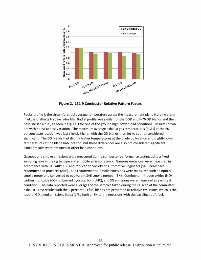
Performance tests were completed over a range of operating conditions from idle to maximum power
conditions including sea level standard (SLS) day No-Load (NL), SLS and hot day ECS (Environmental
Control System), sea level hot day main engine start (MES) and 41,000 feet altitude hot day generator
load. All tests were run at actual engine conditions (not scaled). Fuel flows were adjusted to provide a
constant heat input (MJ/hr) to the combustor, to account for the varying fuel lower heating value (LHV).
There was no fuel effect on combustor pattern factor (PF) (Figure 2) or radial profile (Figure 3). PF and
radial profile are measures of the temperature distribution at the turbine stator inlet plane (combustor
exit). PF is the ratio of the difference between the maximum and average temperature at the turbine
inlet plane to the combustor temperature rise, and affects turbine stator life. PF with the DGD and F-76
GD blends were similar to the baseline Jet A fuel at all high power load conditions, and slightly higher
than the Jet A baseline at the sea level (SL) NL condition. PF at NL or idle conditions are not significant
due to the low turbine inlet temperatures. All PFs were well below the design limit.
65
DISTRIBUTION STATEMENT A: Approved for public release. Distribution is unlimited.
Figure 2. 131-9 Combustor Relative Pattern Factor.
Radial profile is the circumferential average temperature across the measurement plane (turbine stator
inlet), and affects turbine rotor life. Radial profile was similar for the DGD and F-76 GD blends and the
baseline Jet A fuel, as seen in Figure 3 for one of the ground high power load conditions. Results shown
are within test-to-test variation. The maximum average exhaust gas temperatures (EGTs) at the 60
percent span location was just slightly higher with the GD blends than Jet A, but not considered
significant. The GD blends had slightly higher temperatures at the blade tip location and slightly lower
temperatures at the blade hub location, but these differences are also not considered significant.
Similar results were obtained at other load conditions.
Gaseous and smoke emissions were measured during combustor performance testing using a fixed
sampling rake in the rig tailpipe and a mobile emissions truck. Gaseous emissions were measured in
accordance with SAE ARP1156 and reduced to Society of Automotive Engineers (SAE) aerospace
recommended practices (ARP) 1533 requirements. Smoke emissions were measured with an optical
smoke meter and converted to equivalent SAE smoke number (SN). Combustor nitrogen oxides (NOx),
carbon monoxide (CO), unburned hydrocarbon (UHC), and SN emissions were measured at each test
condition. The data reported were averages of the samples taken during the PF scan of the combustor
exhaust. Test results with the 5 percent GD fuel blends are presented as relative emissions, which is the
ratio of GD blend emissions index (g/kg fuel) or SN to the emissions with the baseline Jet A fuel.

66
DISTRIBUTION STATEMENT A: Approved for public release. Distribution is unlimited.
Figure 3. 131-9 Radial Profile at SL 39°C MES Load Condition.
The NOx, CO, and UHC emissions with the DGD and F-76 GD blends were comparable at all conditions to
results with the baseline Jet A fuel. NOx emissions were similar for both fuels at all conditions (Figure 4).
The UHC and CO emissions were also similar at all loaded conditions (Figure 5). UHC and CO emissions
are significant only at the NL and altitude generator load condition. CO and UHC variations at the high
power conditions [environmental control system (ECS) and MES] are not considered significant due to
the very low emissions levels, and since small changes in measured values result in large percent
changes. Smoke emissions with the GD blends were reduced approximately 20 percent at most higher
power conditions (Figure 6), but fuel aromatic content which normally correlates well with SN decreased
less than 6%v due to the low blend ratio. Smoke emissions were very low (SN < 10) at all conditions with
all fuels, so small variation in SN with the GD blends can lead to large changes relative to the baseline.
Smoke emissions at the altitude generator load condition (41K shp) were not reported as they were
below the instrument detection limit.
Test results showed no adverse effect of the 5 percent GD fuel blends on engine gaseous emissions, with
a slight reduction in smoke emissions at high power conditions which could improve local air quality
near the airport.

67
DISTRIBUTION STATEMENT A: Approved for public release. Distribution is unlimited.
Figure 4. 131-9 Rig NOx Relative Emissions.
Figure 5. a) 131-9 Rig CO and b) UHC Relative Emissions.

68
DISTRIBUTION STATEMENT A: Approved for public release. Distribution is unlimited.
Figure 6. 131-9 Rig Relative Smoke Emissions.
LBO tests were run at simulated engine NL (idle) conditions over the operating envelope (SL up to
41,000 feet altitude). After stabilizing at each condition, the fuel flow rate was slowly decreased while
holding combustor inlet conditions constant and continuously recording data. Blowout was detected
when the measured combustor exit temperatures suddenly dropped. Blowout test results were
correlated against a corrected reference velocity (corrected airflow). Test results (Figure 7) showed no
significant difference in LBO fuel-air ratios (FARs) due to fuel type over the range of test conditions, and
no loss in blowout margin (difference between NL fuel flows and the LBO line). LBO characteristics with
both the baseline and 5 percent GD blends were consistent with expectations based on previous
Honeywell rig testing.
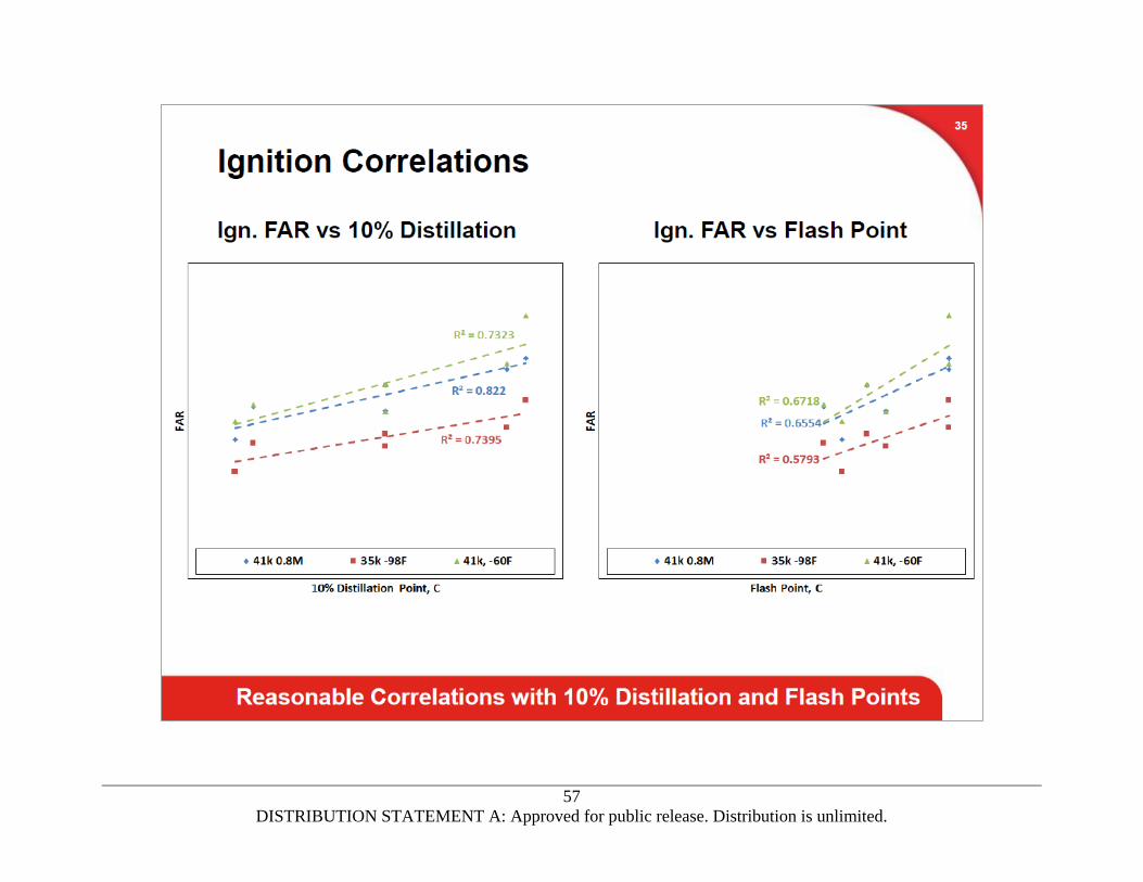
Lean ignition tests were run at simulated APU ground and altitude start conditions from SL up to 41,000
feet altitude. Fuel temperatures varied at each test condition, and ranged from ambient to -37°C. After
stabilizing at each condition, an ignition attempt was performed at varying fuel flows until the minimum
fuel flow for acceptable ignition delay was found. Fuel temperatures and flows were preset in a bypass
circuit, and then directed to the combustor through a three-way solenoid valve. Ignition delay is defined
as the time from when the fuel is introduced and the igniter switched on until ignition was detected by a
rise in combustor exit temperature. The lean ignition FAR is reported as a function of corrected
reference velocity (corrected airflow). Test results (Figure 8) show lean ignition FARs with the 5 percent
GD blends were the same or slightly lower than the baseline Jet A fuel, presumably due to the same
front end distillation (from Jet A). Even though the 5 percent GD blend freeze points were above the
D1655 specification maximum (-40°C), there were no difficulties is setting up and running the cold
ignition tests at -37°C fuel temperature. Ignition characteristics with the baseline and GD blends were
consistent with expectations based on previous Honeywell rig testing, which were run with slightly
warmer fuel temperatures (ambient to -27°C).

69
DISTRIBUTION STATEMENT A: Approved for public release. Distribution is unlimited.
Figure 7. 131-9 Rig Lean Blowout Results.
Figure 8. 131-9 Rig Lean Ignition Results.
Combustor rig test results showed there was no adverse effect of 5 percent GD blends on combustion
performance, exhaust emissions, LBO, or lean ignition characteristics.

70
DISTRIBUTION STATEMENT A: Approved for public release. Distribution is unlimited.
Atomizer Cold Plugging Test
Atomizer cold plugging tests were run in April 2014 to evaluate if high freeze point hydrocarbons or
contaminants in the 5 percent GD blends would cause atomizer plugging when cold soaked at -40°C.
This test was originally run in 2010 on a contaminated HEFA fuel that caused plugging during an ONERA
cold ignition bench test. The ONERA plugging results were duplicated on the Honeywell test setup with
the ONERA HEFA fuel blend, and showed no plugging after the high boiling contaminant was removed.
The test is run in a simple pipe rig installed in the C-100 combustor test facility, with a medium-sized
pressure atomizer setup to spray horizontally. The fuel was pre-conditioned to -15°C in a bypass loop,
with an APU fuel control providing a constant pre-set fuel flow. The rig air flowing past the atomizer
was chilled to -40°C at half an atmosphere pressure and moderate velocity. The test is performed by
directing the fuel flow to the atomizer for approximately 10 seconds, then diverting the fuel back to the
bypass circuit for 10 minutes. The atomizer is cold soaked during the entire test period. The cycle was
repeated six times to see if any atomizer plugging was observed. Plugging would be observed by an
increase in fuel pressure at the atomizer inlet for a constant fuel flow.
Test fuels included baseline Jet A (D1655), 5 percent DGD blend, and 5 percent F-76 GD blend. Key fuel
properties are shown in Table 4.
Table 4. Fuel Properties for Atomizer Plugging Test.
Specific
Gravity
Viscosity
at 25° (cSt)
Freeze Point
(°C)
Water Content
(ppm)
Jet A Baseline 0.817 1.69 -45 39
5% Diamond GD 0.814 1.78 -39 36
5% Navy F-76 GD 0.815 1.77 -38 36
(1) Calculated
Test results showed no indication of plugging with the Jet A or the two 5 percent GD blends, with fuel
pressure constant for each fuel pulse.
Atomizer plugging was not observed with any of the test fuels, including the GD blends with freeze point
(D2386) slightly above the cold soak temperatures.
Atomizer Cold Spray Testing
Onboard APUs are required to provide reliable cold and high altitude starting if there is a main engine
generator failure or an in-flight shutdown of a main engine. Since the APU is normally off in-flight, the
APU and its fuel supply can be cold-soaked which makes atomization of the fuel critical to reliable

71
DISTRIBUTION STATEMENT A: Approved for public release. Distribution is unlimited.
starting. In contrast, most main engines have a fuel-oil heat exchanger (HX) which warms the fuel prior
to the inlet fuel filter. The APU and main engine have similar ground cold start requirements.
Honeywell completed atomizer cold bench spray tests to determine fuel effects on atomization and
spray quality, and by inference, APU or engine cold ignition. Pressure atomizers typical of those used on
APUs and small propulsion engines, or as start injectors for main propulsion engines were selected for
testing. Atomizer performance parameters including fuel flow, spray droplet size, and spray
characteristics were measured over a range of conditions.
Two pressure atomizers were used for testing. Atomizer A was a small flow number (FN) atomizer
typical of those used on newer transport and military APUs. Atomizer B was a large FN atomizer typical
of secondary atomizers used on older commercial and military transport APUs or on can-type
combustion systems. FN is an indication of the atomizer size, and is the fuel flow (lb/hr) divided by the
square root of the fuel pressure (psid). Small FN atomizers are normally the most sensitive to fuel
property variations.
Four test fluids were used for testing including standard calibrating fluid (MIL-PRF-7024 Type II), Jet A
(D1655), a 2 percent DGD fuel blend, and Viscor 12 cSt calibrating fluid. The Jet A provided by
Honeywell was from the standard laboratory facility fuel supply.
Table 5 summarizes fuel properties important to atomization, including specific gravity (D1298) and
viscosity (D445). Freeze point was measured by D2386. Spray tests were conducted with warm 2
percent F-76 GD blend, but cold spray tests were not conducted with this fluid due to budget limitations.
Spray results with the warm 2 percent F-76 GD blend were similar to the results with warm 2 percent
DGD, so are not shown.
Each atomizer was tested over a range of conditions representative of typical engine start conditions.
For pressure atomizers, this required a range of inlet fuel pressures. The fuels were all run at ambient
~27°C (80°F) and -40°C (-40°F) fluid temperatures. The Viscor fluid was run at a temperature to provide
12 cSt viscosity (around 27°C). Sauter mean diameter (SMD) was used as a measure of atomization
quality, which has been shown to correlate well with engine ignition and blowout characteristics. SMD
measurements (microns) were obtained with a Malvern Spraytec particle analyzer. Test results are
presented with spray SMD normalized to 7024 II calibrating fluid.
Table 5. Atomization Test Fluid Properties.
Fluid
Specific Gravity
Viscosity
(cSt at 25oC)
Viscosity
(cSt at -40oC) (1)
Freeze Point
(oC)
7024 II 0.766 1.2 n/a na
Jet A 0.814 1.7 9.5 -46
2% DGD Blend 0.817 1.8 11.2 -41

72
DISTRIBUTION STATEMENT A: Approved for public release. Distribution is unlimited.
Fluid
Specific Gravity
Viscosity
(cSt at 25oC)
Viscosity
(cSt at -40oC) (1)
Freeze Point
(oC)
Viscor 0.874 11.9 n/a na
(1) calculated
Figure 9(a) shows the warm 2 percent DGD blend had spray droplet size (SMD) for atomizer A (smallest
FN) similar to that of Jet A, while cold 2 percent DGD had much larger (worse) SMD over the entire
pressure range tested. SMDs with the 2 percent DGD blend were also much larger than the Viscor 12
cSt fluid. The reason the atomizer A spray droplet size increased so significantly with the cold 2 percent
DGD blend is not known, as the fluid viscosity was calculated to be less than 12 cSt at the -40°C test
temperature. There could have been an instrument calibration or measurement error, or small wax
particles may have formed between the fuel chiller and the atomizer. Spray angles for atomizer A
presented in Figure 9(b) show spray angles for both cold Jet A and 2 percent DGD similar to spray angles
for the more viscous Viscor 12 cSt fluid at higher fuel pressures, but the 2 percent DGD spray angle
drops below the Viscor values at low fuel pressures. Figure 10 shows photographs of the cold spray at
50 psid with Viscor, Jet A, and the 2 percent DGD, where the narrow angle for the DGD blend is clearly
evident. Spray collapse with viscous fluids at low fuel pressures is normal, but the sharp drop in spray
angle with cold 2 percent DGD fuel is a concern. Due to the irregularities in both droplet size and spray
angle measurements with the 2 percent DGD blend, it is recommended that the cold spray tests with
the 2 percent DGD blend be repeated with the small pressure atomizer, and cold spray tests run with
the 2 percent F-76 GD blend.
Figure 9. Comparison of Small Atomizer a) Droplet Size, b) Spray Angle.

73
DISTRIBUTION STATEMENT A: Approved for public release. Distribution is unlimited.
Figure 10. Cold Spray Photographs at 50 psid for a) Viscor, b) Jet A, c) 2% DGD.
SMD results for the larger pressure atomizers (atomizer B) presented in Figure 11(a) were similar for Jet
A and the 2 percent DGD blend, and below values for the Viscor 12 cSt fluid. Spray angle with the larger
atomizer B presented in Figure 11(b) shows a smaller spray angle for the 2 percent DGD blend at most
fuel pressures, but all angles are acceptable with no sharp collapse in angle at lower fuel pressures.
Figure 11. Comparison of Large Atomizer a) Droplet Size, b) Spray Angle.
Atomizer cold (-40°C) spray tests showed spray characteristics with the small pressure atomizer and 2
percent DGD blend were acceptable at higher pressure, but degraded below conventional Jet A fuel and
the Viscor calibrating fluid at lower pressures. Cold spray tests with the larger pressure atomizer
showed similar results for Jet A, the 2 percent DGD blend, and Viscor 12 cSt fluid. It is recommended
that the cold spray tests with the 2 percent DGD blend be repeated with the small pressure atomizer,
and tests run with the 2 percent F-76 GD blend.

74
DISTRIBUTION STATEMENT A: Approved for public release. Distribution is unlimited.
131-9 APU Cold and Altitude Start Testing
The objectives of this test were to determine the effects of a 2percent DGD blend on the cold and
altitude start capability of the 131-9 APU. The 131-9 APU is a small gas turbine engine used in a number
of commercial (B737, A320) and military (C-40, P-8) applications. The 131-9 APU (Figure 12) is a
constant speed, load compressor type engine with a pressure ratio (PR) of approximately 7, and a
reverse flow annular combustion system with dual-orifice pressure type fuel atomizers. APUs are used
to provide aircraft secondary power (bleed air for cabin conditioning and generator load for electrical
power) and MES capability on the ground and
in flight.
Figure 12. 131-9 APU.
A development 131-9A APU was installed in large altitude cold chamber No. 1 (LACC 1) test cell (Figure
13a). APU starts (Table 6) were run at base level cold day (-40°C), standard day (15°C), and hot day
(55°C) conditions on the ground, and cold day (-70°C) and hot day (-14°C) at the 39,000 feet maximum
start altitude. The engine was installed in a cold box inside the altitude chamber to simulate the APU
compartment in the aircraft, and soaked at the start temperature as required (up to 6 hours) prior to
initiating the start to allow the engine, oil, and fuel to stabilize at the desired temperatures. A fuel coil
located inside the cold box provides enough conditioned fuel for the start transient and initial APU on-
speed operation. The APU had a ducted inlet to match the aircraft installation, with APU inlet pressure,
air temperature, and ram air pressure drop (airflow) adjusted to simulate the APU inlet conditions in
flight. The
131-9A APU has an electric starter, with the battery power provided matching previous testing.
Tests with the 2 percent DGD fuel and the baseline Jet A fuels were conducted in December 2015. Tests
with the 2 percent F-76 GD blend were not run due to funding limitations and the similarity to the 2
percent DGD blend.
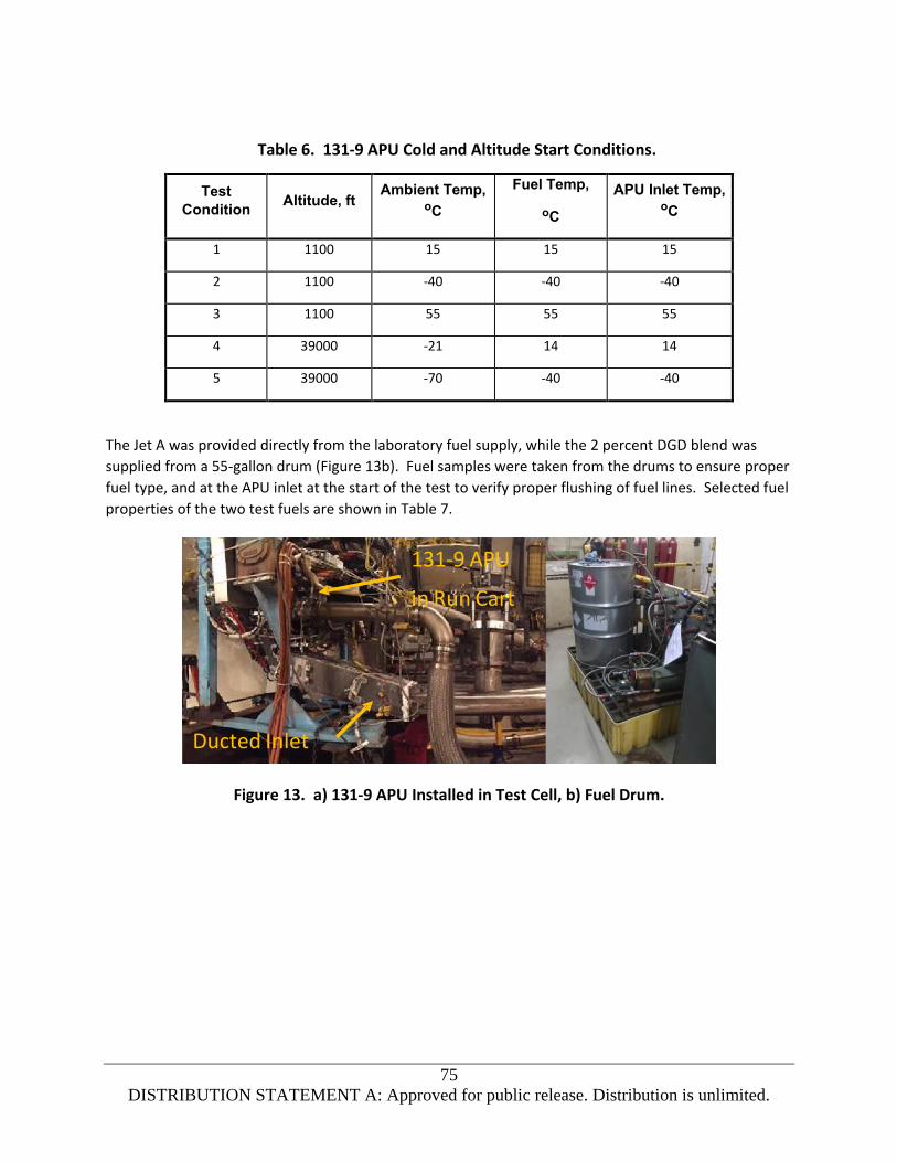
75
DISTRIBUTION STATEMENT A: Approved for public release. Distribution is unlimited.
Table 6. 131-9 APU Cold and Altitude Start Conditions.
Test
Condition Altitude, ft
Ambient Temp, oC
Fuel Temp,
oC
APU Inlet Temp, oC
1 1100 15 15 15
2 1100 -40 -40 -40
3 1100 55 55 55
4 39000 -21 14 14
5 39000 -70 -40 -40
The Jet A was provided directly from the laboratory fuel supply, while the 2 percent DGD blend was
supplied from a 55-gallon drum (Figure 13b). Fuel samples were taken from the drums to ensure proper
fuel type, and at the APU inlet at the start of the test to verify proper flushing of fuel lines. Selected fuel
properties of the two test fuels are shown in Table 7.
Figure 13. a) 131-9 APU Installed in Test Cell, b) Fuel Drum.
131-9 APU
in Run Cart
Ducted Inlet

76
DISTRIBUTION STATEMENT A: Approved for public release. Distribution is unlimited.
Table 7. Fuel Properties for APU Cold and Altitude Start Test.
Fuel Property Jet A 2% DGD
Specific Gravity (D1298) 0.818 0.817
Viscosity, cSt at -40°C (D445) (1) 10.8 11.2
10% Dist Temp, °C (D86) 176 172
Freeze Point, °C (D2386) -43 -41
Water, ppmw (E1064) 45 30
(1) calculated
All starts from base level to 39,000 feet altitude and from hot to cold day with the 2 percent DGD fuel
were successful, and similar to starts with the baseline Jet A fuel. Only normal start-to-start differences
were seen between the Jet A and 2 percent DGD blend, with similar start times, combustor ignition
delays, fuel flows (WF), primary fuel pressures (PFPRIM), and maximum EGTs (TTDEA). Figure 14 shows
start traces for base level -40°C for Jet A, and Figure 15 for 39K feet altitude -40°C condition.
Figure 14. Start Traces for Base Level -40°C with a) Jet A, and b) 2% DGD.

77
DISTRIBUTION STATEMENT A: Approved for public release. Distribution is unlimited.
Figure 15. Start Traces for 39K Feet Altitude -40°C with a) Jet A, and b) 2% DGD.
There was a fluctuation in fuel flow at the 39K foot cold condition with the 2 percent DGD fuel when the
fuel flow was trimmed to the minimum fuel schedule, which may be an indication of marginal
atomization or the combustor near blowout.
APU cold and altitude starts tests were successful with a 2 percent DGD fuel blend over a range of
ground and altitude start conditions. Start times, combustor ignition delay times, and EGTs during the
start were similar for the 2 percent DGD blend and the Jet A baseline fuel at all test conditions. Test
results show there would be no adverse effect of a 2 percent DGD fuel blend on APU cold or altitude
start reliability, but there were fuel flow fluctuations with the DGD blend at maximum altitude cold start
conditions that may be due to marginal atomization. It is recommended that the viscosity of GD fuel
blends be limited to 12 cSt maximum at -40°C for Jet A fuel in the D7566 specification to ensure there is
no increase in viscosity relative the current jet fuel pool.
The viscosity of Jet A-1 blends should be limited to 10 cSt maximum at -40°C. This corresponds to 12 cSt
maximum at -44°C, which is the low temperature operating limit for
Jet A-1 fuel in most aircraft. The freeze point of GD blends should be well below the specification
minimum (-40°C for Jet A, -47°C for Jet A-1) to provide margin for long flights where fuel in the APU
compartment can be cold soaked.
Summary
Combustor rig tests completed with 5 percent GD blends showed there was no adverse impact on
combustor performance (PF or profile), exhaust emissions, LBO, or lean ignition. Atomizer cold plugging
tests with 5 percent GD blends showed no plugging from high boiling hydrocarbons or contaminants.
APU cold and altitude start tests completed with a 2 percent DGD blend showed successful starting over
the start envelope, but did have fuel flow fluctuations at high altitude cold start conditions that may be
due to marginal atomization. Cold spray tests with a 2 percent DGD blend showed droplet size much
larger than cold Jet A and the Viscor 12 cSt calibrating fluid, possibly due to wax formation in the
78
DISTRIBUTION STATEMENT A: Approved for public release. Distribution is unlimited.
upstream fuel chiller. It is recommended that the cold spray tests with the 2 percent DGD blend be
repeated, and cold spray tests run with the 2 percent F-76 blend.
It is recommended that the viscosity of the GD blends be limited in the D7566 specification to 12 cSt
maximum at -40°C for Jet A and 10 cSt maximum for Jet A-1 to ensure there is no increase in viscosity
relative to the current jet fuel pool. The freeze point of GD blends should be well below the D7566
specification minimum (-40°C for Jet A, -47°C for Jet A-1) to provide margin for long flights where fuel in
the APU compartment can be cold soaked.

79
DISTRIBUTION STATEMENT A: Approved for public release. Distribution is unlimited.
APPENDIX 3. HONEYWELL TESTS TO EVALUATE
A LOW FREEZE POINT GREEN DIESEL FUEL BLEND
(13 pages)

80
DISTRIBUTION STATEMENT A: Approved for public release. Distribution is unlimited.
Honeywell Tests to Evaluate a Low Freeze Point Green Diesel Fuel Blend
Component and combustor rig tests of a low freeze point hydroprocessed esters and fatty acids (HEFA)
fuel blend, also called Green Diesel (GD) blend, was completed at the Honeywell Aerospace facility in
Phoenix, Arizona. Funding for the testing was provided by the Air Force Research Laboratory (AFRL). All
findings and conclusions expressed are those of the authors (Honeywell) and do not necessarily reflect
the views of the contracting agency.
The purpose of the testing was to evaluate the effect of GD fuel blends on the performance, operability,
and emissions of aircraft gas turbine engines. Blends of a low freeze point HEFA synthetic paraffinic
kerosene (SPK) in the diesel fuel boiling range with conventional petroleum derived jet fuel were
evaluated.
The following evaluation tests were completed using the GD fuel blend and a baseline fuel:
131-9 APU combustor rig performance, emissions, lean blowout (LBO), and lean ignition tests
Fuel atomizer cold spray test
Green Diesel Blending Component
The low freeze point GD SPK was provided by Neste Corporation in Finland. Two 55-gallon drums of the
Neste GD SPK were provided, with select properties shown in Table 1. The density, freeze point,
distillation 10 percent point, and distillation end point of the GD SPK blending component were above
the current HEFA SPK specification limits (D7566-16). A GCxGC gas chromatography analysis of the neat
GD SPK was performed by AFRL, with the chromatogram shown in Figure 1.
Figure 1. Neste Green Diesel Synthetic Paraffinic Kerosene GCxGC Chromatogram.
12866 NEXBTL Diesel

81
DISTRIBUTION STATEMENT A: Approved for public release. Distribution is unlimited.
The Neste GD SPK is primarily (>92 percent by weight) iso-paraffins with carbon numbers up to 27 (small
quantities), with higher concentrations up to a carbon number of 20.
When a low freeze point GD SPK is blended into jet fuel in varying concentrations depending on the
properties of the petroleum derived jet fuel blending component, the final blended fuel can meet all
D7566 Table 1 requirements.
Fuel for each Honeywell test series was blended just prior to the test, so there were some test to test
variations in both the baseline fuel and GD blend properties. The 30 percent Neste GD blends tested
met specification requirements for all properties tested. The low freeze point Neste GD SPK was blended
with a light JP-8 fuel to maximize the amount of GD SPK in the blend. The final blend ratio was 30
percent by volume GD SPK, which was set by viscosity limitations (12 cSt maximum at -40oC).
Table 1. Green Diesel SPK Properties
Fuel Property 100% Neste
Green Diesel
D7566 Annex A2
(HEFA SPK) Spec
Limits
D7566 Table 1
(HEFA Blend) Spec
Limits
Density (D1298) 781 730 to 770 775 to 840
Temp, oC for 12 cSt viscosity (1) -10
Viscosity, cSt at -20oC (D445) (1) 18.7 8 max
Viscosity, cSt at -20oC (D445) 19.2 8 max
Dist IBP, oC (D86) 158
10% Dist Temp, oC (D86) 260 205 max 205 max
20% Dist Temp, oC (D86) 271
50% Dist Temp, oC (D86) 281 report report
90% Dist Temp, oC (D86) 291 report report
Dist FBP, oC (D86) 306 300 max 300 max
Dist T50-T10, oC (D86) 21 15
Dist T90-T10, oC (D86) (1) 31 20 40
Flash Point, oC (D56) (1) 64 38 min 38 min
LHV, MJ/kg (D240) 43.97 42.8 min
Smoke Point, mm (D1322) >50 25.0 min
Aromatics, %v (D1319) 0.0 0.5 max 8 to 25
Freeze Point, oC (D2386) -30 -40 max -40 max

82
DISTRIBUTION STATEMENT A: Approved for public release. Distribution is unlimited.
Fuel Property 100% Neste
Green Diesel
D7566 Annex A2
(HEFA SPK) Spec
Limits
D7566 Table 1
(HEFA Blend) Spec
Limits
Freeze Point, oC (D5972) -29 -40 max -40 max
(1) Calculated
131-9 Combustor Rig Testing
131-9 combustor rig testing was completed to determine the effect of the GD fuel blend on combustion
system performance. A full scale 131-9 combustor rig was installed in the combustion test facility
(Figure 2) in Phoenix, Arizona with tests completed in August of 2016.
The test fuels for combustor rig testing consisted of a Jet A baseline, the JP-8 blending component, and
the 30 percent GD blend.
The 30 percent GD blend was supplied to the test cell from a 55-gallon drum, while the Jet A and JP-8
were provided from the standard laboratory fuel supply. Jet A is the normal baseline fuel and was run
for all tests, while JP-8 was run for performance and emissions tests since it was the major blending
component in the 30 percent GD blend. Table 2 provides properties of the Jet A and GD blend used for
combustor rig ignition testing, while Table 3 provides Jet A, JP-8, and GD blend properties used for
combustor rig performance, lean blowout, and emissions testing.
The 30 percent GD blend met all specification properties tested, except for aromatics which was slightly
below the current D7566 specification limit due to the relatively low aromatics of the JP-8 blending
component.
Figure 2. a) 131-9 Rig Installed in Test Cell, b) Mobile Emissions Truck, c) Fuel Drums.
131 - 9 Combustor Rig
Inlet
Exhaust
Cold Fuel Cart
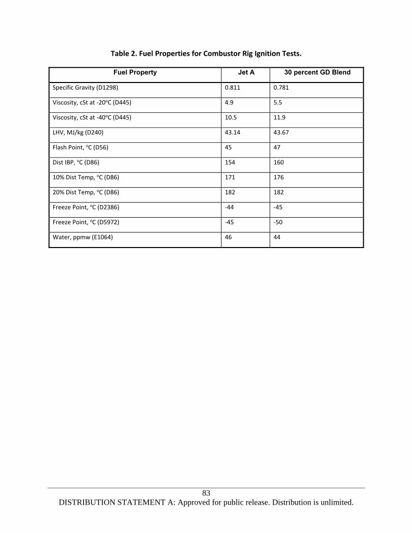
83
DISTRIBUTION STATEMENT A: Approved for public release. Distribution is unlimited.
Table 2. Fuel Properties for Combustor Rig Ignition Tests.
Fuel Property Jet A 30 percent GD Blend
Specific Gravity (D1298) 0.811 0.781
Viscosity, cSt at -20oC (D445) 4.9 5.5
Viscosity, cSt at -40oC (D445) 10.5 11.9
LHV, MJ/kg (D240) 43.14 43.67
Flash Point, oC (D56) 45 47
Dist IBP, oC (D86) 154 160
10% Dist Temp, oC (D86) 171 176
20% Dist Temp, oC (D86) 182 182
Freeze Point, oC (D2386) -44 -45
Freeze Point, oC (D5972) -45 -50
Water, ppmw (E1064) 46 44

84
DISTRIBUTION STATEMENT A: Approved for public release. Distribution is unlimited.
Table 3. Fuel Properties for Combustor Rig Performance and Emission Tests.
Fuel Property Jet A JP-8 30 percent GD Blend
Specific Gravity (D1298) 0.811 0.780 0.780
Viscosity, cSt at -20oC (D445) 4.9 3.6 5.5
Dist IBP, oC (D86) 160 160 160
10% Dist Temp, oC (D86) 172 170 177
20% Dist Temp, oC (D86) 182 177 183
50% Dist Temp, oC (D86) 204 188 209
90% Dist Temp, oC (D86) 249 216 284
Dist FBP, oC (D86) 282 242 298
Flash Point, oC (D56) 46 47 49
LHV, MJ/kg (D240) 43.11 43.51 43.71
Smoke Point, mm (D1322) 23 30 32
Aromatics, %v (D1319) 18.0 11.5 7.0
Naphthalenes, %v (D1840) 0.15 - - 0.03
Freeze Point, oC (D2386) -48 -55 -44
Freeze Point, oC (D5972) -47 -55 -48
Water, ppmw (E1064) 68 71 104
GCxGC chromatograms for the Jet A and 30 percent GD blend are shown in Figures 3 and 4 respectively.

85
DISTRIBUTION STATEMENT A: Approved for public release. Distribution is unlimited.
Figure 3. Jet A GCxGC Chromatogram.
Figure 4. 30 Percent Low Freeze Point Green Diesel Blend Chromatogram.
Performance tests were completed over a range of operating conditions from idle to maximum power
conditions including sea level standard day No-Load (NL), sea level standard and hot day ECS
(Environmental Control System), sea level hot day MES (Main Engine Start) and 41,000 feet altitude hot
day generator load. All tests were run at actual engine conditions (not scaled). Fuel flows were adjusted
to provide a constant heat input (MJ/hr) to the combustor, to account for the varying fuel lower heating
value (LHV).
There was no fuel effect on combustor pattern factor (Figure 5) or radial profile (Figure 6). Pattern
factor (PF) and radial profile are measures of the temperature distribution at the turbine stator inlet
plane (combustor exit). PF is the ratio of the difference between the maximum and average
12865 – Jet A
12869 JP-8 / 30%
NEXBTL Diesel

86
DISTRIBUTION STATEMENT A: Approved for public release. Distribution is unlimited.
temperature at the turbine inlet plane to the combustor temperature rise, and affects turbine stator life.
Pattern factor with the 30 percent GD blend was similar to the baseline Jet A and JP-8 fuels at all high
power load conditions, within normal test to test variation. All pattern factors were well below the
design limit.
Figure 5. 131-9 Combustor Relative Pattern Factor.
Radial profile is the circumferential average temperature across the measurement plane (turbine stator
inlet), and affects turbine rotor life. Radial profile was similar for the 30 percent GD blend and the
baseline Jet A and JP-8 fuels, as seen in Figure 6 for one of the ground high power load conditions.
Results shown are within test to test variation. The GD blend had slightly higher temperatures at the
blade tip location and slightly lower temperatures at the blade hub location, but these differences are
not considered significant. Similar results were obtained at other load conditions.
MES Deteriorated Engine 103°F
0.0
0.2
0.4
0.6
0.8
1.0
1.2
1.4
1.6
1.8
2.0
JP-8
30 % Neste GD

87
DISTRIBUTION STATEMENT A: Approved for public release. Distribution is unlimited.
Figure 6. 131-9 Radial Profile at SL 39°C MES Load Condition.
Gaseous and smoke emissions were measured during combustor performance testing using a fixed
sampling rake in the rig tailpipe and a mobile emissions truck. Gaseous emissions were measured in
accordance with SAE ARP1156 and reduced to SAE ARP 1533 requirements. Smoke number (SN)
emissions were measured with an optical smoke meter and converted to equivalent SAE smoke number.
Combustor nitrogen oxides (NOx), carbon monoxide (CO), unburned hydrocarbon (UHC), and SN
emissions were measured at each test condition. Test results with the JP-8 and 30 percent GD blend are
presented as relative emissions, which is the ratio of emissions index (g/kg fuel) or smoke number to
emissions with the baseline Jet A fuel.
NOx emissions with the 30 percent GD blend were the same as JP-8 and the baseline Jet A fuel at all
conditions (Figure 7). The UHC and CO emissions of the 30 percent GD blend and JP-8 were similar at all
conditions (Figure 8), with both slightly lower than the baseline Jet A. The CO emissions for the GD
blend were slightly higher than JP-8 at all conditions, but both were below Jet A values. CO and UHC
variations at the high power conditions (ECS and MES) are not considered significant due to the very low
emissions levels, and since small changes in measured values results in large percent changes. UHC and
CO emissions are significant only at the No-Load and altitude generator load conditions.
Smoke emissions with JP-8 and the GD blend were reduced over 55 and 70 percent respectively from
the baseline Jet A fuel at all higher power conditions (Figure 9) due to the lower fuel aromatic content
(Jet A 18.0 percent v, JP-8 11.5 percent v, GD blend 8.0 percent v). SN emissions were very low (SN < 10)
at all conditions with all fuels, so small changes in measured smoke emission values result in large
percentage changes. SN emissions at the altitude generator load condition (41K shp) were not reported
as they were below the instrument detection limit.
0
10
20
30
40
50
60
70
80
90
100
-80 -60 -40 -20 0 20 40
T-T39 AVE, °F
Jet A Baseline
JP-8
30% Neste GD
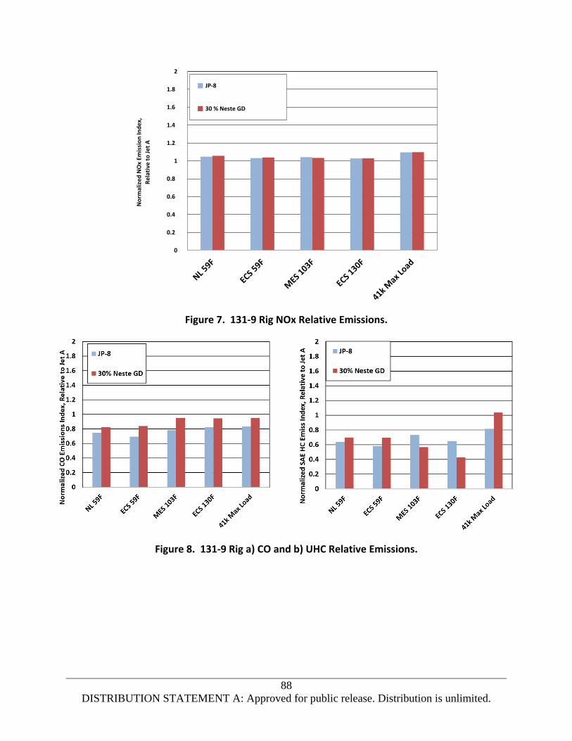
88
DISTRIBUTION STATEMENT A: Approved for public release. Distribution is unlimited.
Figure 7. 131-9 Rig NOx Relative Emissions.
Figure 8. 131-9 Rig a) CO and b) UHC Relative Emissions.
0
0.2
0.4
0.6
0.8
1
1.2
1.4
1.6
1.8
2
JP-8
30 % Neste GD

89
DISTRIBUTION STATEMENT A: Approved for public release. Distribution is unlimited.
Figure 9. 131-9 Rig Relative Smoke Emissions.
Emission test results showed no adverse effect of the 30 percent GD fuel blend on engine gaseous
emissions, with a reduction in smoke emissions which could improve local air quality near the airport.
Lean blowout tests were run at simulated engine No-Load (idle) conditions or part speed conditions over
the operating envelope (sea level up to 41,000 feet altitude). After stabilizing at each condition, the fuel
flow rate was slowly decreased while holding combustor inlet conditions constant and continuously
recording data. Blowout was detected when the measured combustor exit temperatures suddenly
dropped. Ambient fuel temperatures were used for blowout testing. Blowout test results were
correlated against a corrected reference velocity (corrected airflow). Test results (Figure 10) showed a
small increase in lean blowout fuel-air ratio with the 30 percent GD blend at the two high altitude
conditions, which is a small loss of blowout margin.
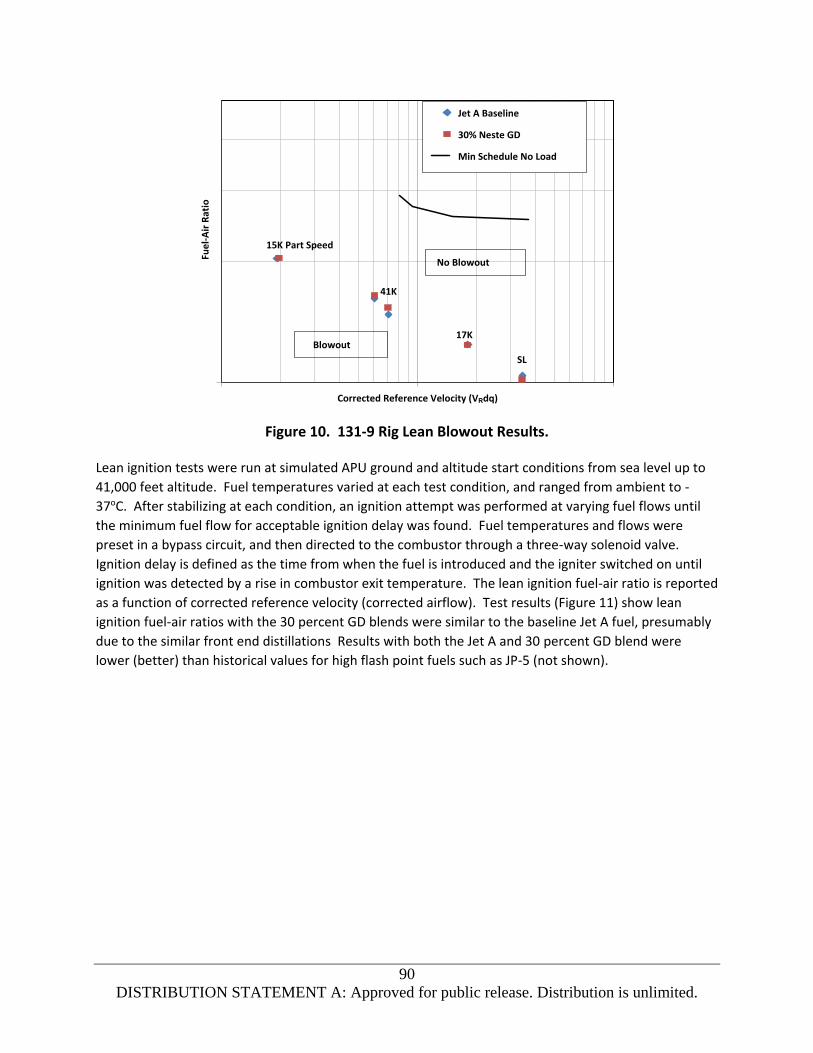
90
DISTRIBUTION STATEMENT A: Approved for public release. Distribution is unlimited.
Figure 10. 131-9 Rig Lean Blowout Results.
Lean ignition tests were run at simulated APU ground and altitude start conditions from sea level up to
41,000 feet altitude. Fuel temperatures varied at each test condition, and ranged from ambient to -
37oC. After stabilizing at each condition, an ignition attempt was performed at varying fuel flows until
the minimum fuel flow for acceptable ignition delay was found. Fuel temperatures and flows were
preset in a bypass circuit, and then directed to the combustor through a three-way solenoid valve.
Ignition delay is defined as the time from when the fuel is introduced and the igniter switched on until
ignition was detected by a rise in combustor exit temperature. The lean ignition fuel-air ratio is reported
as a function of corrected reference velocity (corrected airflow). Test results (Figure 11) show lean
ignition fuel-air ratios with the 30 percent GD blends were similar to the baseline Jet A fuel, presumably
due to the similar front end distillations Results with both the Jet A and 30 percent GD blend were
lower (better) than historical values for high flash point fuels such as JP-5 (not shown).
Jet A Baseline
30% Neste GD
Min Schedule No Load
No Blowout
Blowout
41K
17K
SL
15K Part Speed
Corrected Reference Velocity (VRdq)

91
DISTRIBUTION STATEMENT A: Approved for public release. Distribution is unlimited.
Figure 11. 131-9 Rig Lean Ignition Results.
Combustor rig test results showed there was no adverse effect of a 30 percent blend of low freeze point
GD SPK and conventional petroleum derived jet fuel on combustion performance (pattern factor and
profile), ignition characteristics, and exhaust gaseous emissions, with a significant reduction in exhaust
smoke emissions. There was a small degradation in lean blowout at several high altitude conditions.
Atomizer Cold Spray Testing
Onboard APUs are required to provide reliable cold and high altitude starting if there is a main engine
generator failure or an in-flight shutdown of a main engine. Since the APU is normally off in-flight, the
APU and its fuel supply can be cold-soaked which makes atomization of the fuel critical to reliable
starting. In contrast, most main engines have a fuel-oil heat exchanger which warms the fuel prior to
the inlet fuel filter. The APU and main engine have similar ground cold start requirements.
Honeywell completed atomizer cold bench spray tests to determine fuel effects on atomization and
spray quality, and by inference, APU or engine cold ignition. Pressure atomizers typical of those used on
APUs and small propulsion engines, or as start injectors for main propulsion engines were selected for
testing. Atomizer performance parameters including fuel flow, spay droplet size, and spray
characteristics were measured over a range of conditions.
Three pressure atomizers were used for testing. Atomizer A was a small FN atomizer typical of those
used on newer transport and military APUs. Atomizer B was a mid-sized FN atomizer typical of primary

92
DISTRIBUTION STATEMENT A: Approved for public release. Distribution is unlimited.
atomizers used on older commercial and military transport APUs, and smaller APUs used on regional
aircraft. Atomizer C was a large FN atomizer typical of secondary atomizers used on older commercial
and military transport APUs or on can-type combustion systems. FN is an indication of the atomizer size,
and is the fuel flow (lb/hr) divided by the square root of the fuel pressure (psid).
Small FN atomizers are normally the most sensitive to fuel property variations.
Four test fluids were used for testing including standard calibrating fluid (MIL-PRF-7024 Type II), Jet A
(D1655), the 30 percent GD fuel blend, and Viscor 12 cSt calibrating fluid. The Jet A provided by
Honeywell was from the standard laboratory facility fuel supply. Table 4 summarizes fuel properties
important to atomization, including specific gravity (D1298) and viscosity (D445).
Each atomizer was tested over a range of conditions representative of typical engine start conditions.
For pressure atomizers, this required a range of inlet fuel pressures. The fuels were all run at ambient
~27oC (80oF) and -40oC (-40oF) fluid temperatures. The Viscor fluid was run at a temperature to provide
12 cSt viscosity (around 27oC). Sauter mean diameter (SMD) was used as a measure of atomization
quality, which has been shown to correlate well with engine ignition and blowout characteristics. SMD
measurements (microns) were obtained with a Malvern Spraytec particle analyzer. Test results are
presented with spray SMD normalized to 7024 II calibrating fluid.
Table 4. Atomization Test Fluid Properties.
Fluid Specific Gravity Viscosity
(cSt at 25oC)
Viscosity
(cSt at -40oC)
Freeze Point
(oC)
Freeze Point
(oC)
D1298 D445 D445 D2386 D5972
7024 II 0.766 1.2 n/a n/a n/a
Jet A 0.803 1.7 9.5 -50 -50
30% GD Blend 0.781 1.9 12.0 -44 -48
Viscor 0.874 11.9 n/a n/a n/a
Figure 12(a) shows the cold 30 percent GD blend had spray droplet size (SMD) for atomizer A (smallest
FN) similar to that of the Viscor 12 cSt fluid for higher pressures tested, but slightly higher (worse) at
lower fuel pressures. SMDs with Jet A were significantly lower than the 30 percent GD blend or Viscor
due to the lower viscosity. Spray angles for atomizer A presented in Figure 12(b) show spray angles for
the 30 percent GD blend were wider (better) than the spray angles for the Viscor 12 cSt fluid above 60
psid, then the spray collapses quickly (Viscor spray collapses below 50 psid). Spray collapse with viscous
fluids at low fuel pressures is normal, but early collapse leads to cold starting concerns. Figure 13 shows
photographs of the cold spray at 50 psid with Viscor, Jet A, and the 30 percent GD blend, where the
narrow angle for the GD blend is clearly evident.

93
DISTRIBUTION STATEMENT A: Approved for public release. Distribution is unlimited.
Results for the other two pressure atomizers (atomizers B and C) showed spray droplet size (SMD) and
spray angle for the 30 percent GD blend were the same or better than values for the Viscor 12 cSt fluid.
Atomizer cold (-40oC) spray tests showed spray characteristics with the small pressure atomizer and 30
percent GD blend were acceptable at higher pressure, but degraded below conventional Jet A fuel and
the Viscor 12 cSt calibrating fluid at lower pressures.
Figure 12. a) Comparison of Small Atomizer Droplet Size, b) Spray Angle.
Figure 13. a) Cold Spray Photographs at 50 psid for Viscor, b) Jet A,
c) 30 percent GD Blend.
Summary
Combustor rig tests completed with 30 percent low freeze point GD blend showed there was no adverse
impact on combustor performance (pattern factor or profile), ignition characteristics or exhaust
emissions, but there was a small degradation in lean blowout characteristics at some test conditions.
Cold spray tests with the medium and large atomizer showed no adverse effect with the 30 percent GD
Viscor Jet A 30% GD

94
DISTRIBUTION STATEMENT A: Approved for public release. Distribution is unlimited.
blend, but with the smallest atomizer both droplet size and spray angle were degraded at low fuel
pressures.
Based on the degradation in lean stability (lean blowout) at high altitude conditions and in spray
characteristics at low fuel pressures for the smallest atomizer, it is recommended that APU system level
start tests be conducted with the 30 percent Neste GD blend to verify there is no adverse effect on APU
cold and altitude start reliability.
Another issue is the 4o to 5oC difference in freeze point between D2386 (manual method) and D5972
(Phase Technology) methods, with D5972 the lower value. Additional laboratory testing is
recommended to determine freeze point with Green Diesel blends with all approved freeze point
instruments.
It is recommended that the viscosity of Green Diesel blends be limited in the D7566 specification to 12
cSt maximum at -40oC for Jet A, to ensure there is no increase in viscosity relative the current jet fuel
pool. A 10 cSt maximum viscosity at -40oC (corresponds to 12 cSt at -44oC) should be imposed for Jet A-
1. This would limit the blend viscosity to the maximum viscosity for reliable engine and APU cold
starting (12 cSt) 3oC below the -47oC freeze point for Jet A-1. The freeze point of GD blends should be
well below the D7566 specification maximum (-40oC for Jet A, -47oC for Jet A-1) to account for
uncertainty in freeze point measurements and to provide margin for long flights where fuel in the APU
compartment can be cold soaked.

95
DISTRIBUTION STATEMENT A: Approved for public release. Distribution is unlimited.
LIST OF ACRONYMS AND ABBREVIATIONS AFRL Air Force Research Laboratory
AO anti-oxidant
APU auxiliary power unit
ARA Applied Research Associates
ARP Aerospace Recommended Practices
CHCJ-5 Catalytic Hydrothermolysis Jet Made to JP-5 Specifications
CI/LI Inhibitor/Lubricity Improver
CLEEN Continuous Lower Energy Emissions and Noise
CO2 carbon dioxide
CO carbon monoxide
DGD Diamond Green Diesel
DLA Defense Logistics Agency
DOD Department of Defense
ECS environmental control system
EGT exhaust gas temperature
FAA Federal Aviation Administration
FID flame ionization detector
FN flow number
FSII fuel system icing inhibitor
GD Green Diesel
HC hydrocarbons
HEFA hydroprocessed esters and fatty acids
HX heat exchanger
ICAO International Civil Aviation Organization

96
DISTRIBUTION STATEMENT A: Approved for public release. Distribution is unlimited.
LACC large altitude cold chamber
lb/hr pounds per hour
LBO lean blowout
LHV lower heating value
LN2 liquid nitrogen
MES main engine start
NDIR non-dispersive infra-red
NIST National Institute of Standards and Technology
NJFCP National Jet Fuel Combustion Program
NL no-load
NOx oxides of nitrogen
OEM original equipment manufacturer
O2 oxygen
PF pattern factor
PR pressure ratio
psid pound(s) per square inch, differential
SAE Society of Automotive Engineers
SDA static dissipator additive
shp shaft horsepower
SL sea level
SLS sea level standard
SMD Sauter mean diameter
SN smoke number
SPK synthetic paraffinic kerosene
TC thermocouple

97
DISTRIBUTION STATEMENT A: Approved for public release. Distribution is unlimited.
TSO Technical Standard Order
UHC unburned hydrocarbon
USAF United States Air Force


