
An Analytical Solution of Shield Tunnel based on
Force Method
Xiaomin You Zixin ZhangYongsheng Li
Dept. of Geotechnical EngineeringTongji University
3nd Sino-Japan Joint Seminarfor the Graduate Students

ITA ( 2000 )Guidelines for the Design of Shield Tunnel Lining


Tunnel projects constructed in Shanghai in recent years
Project Dcal* (m) Thickness (m)
Shanghai Subway Tunnels 5.85 0.35
East Yanan Rd. Tunnel 10.45 0.55
Dalian Rd. Tunnel 10.52 0.48
East Fuxing Rd. Tunnel 10.52 0.48
Xiangyin Rd. Tunnel 10.88 0.48
Shangzhong Rd. Tunnel 13.90 0.60
South Xizang Rd. Tunnel 10.86 0.50
Shanghai Yangtse River Tunnel 14.35 0.65
Large section → low ratio of thickness vs. diameter
Large section → shallow embedded depth

Conventional Model
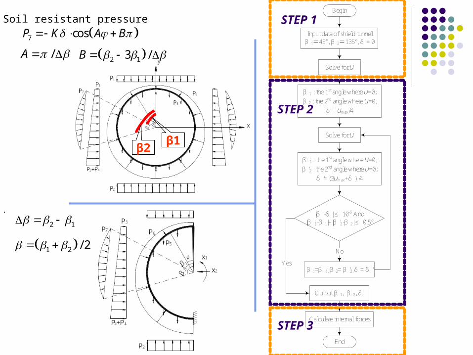
Soil resistant pressure
7 cosP K A B
Begin
Input data of shield tunnelβ 1=45°, β 2=135°, δ = 0
Solve for u
β 1 : the 1st angle where u=0;
β 2 : the 2nd angle where u=0;
δ = umax/4
Solve for u
β '1 : the 1st angle where u=0;
β '2 : the 2nd angle where u=0;
δ '= (3umax+δ ) /4
|δ '-δ | ≤ 10-5 And|β '1-β 1|+|β '2-β 2| ≤ 0.5°
Output β 1, β 2, δ
Calculate internal forces
End
β 1=β '1, β 2= β '2, δ = δ '
No
Yes
/A 2 13 /B
2 1 .
1 2 / 2
STEP 1
STEP 2
STEP 3
β1β2

Deduction based on Force-Method
1st step: Force method equation11 1 1
22 2 2
0
0p
p
x
x
21
11 0
2 32
22 0
M Rds
EI EI
M Rds
EI EI
7
1 11
7
2 21
p pjj
p pjj
0
i pjipj
M Mds
EI
1 2
1 2
1 1 17 7 71 7 0
3 2
1 22 2
2cos cos 2
p p pp
M M M M M Mds ds ds
EI EI EI
K R
EI
1 2
1 2
2 2 27 7 72 7 0
241 2
1 1 2 22 22 2
2 cos cossin sin
2
p p pp
M M M M M Mds ds ds
EI EI EI
K R
EI

2nd step: to solve β1 and β2 7
1
cospj x oj
u u u v
u xpx
M Mu Rd
EI
u pjpj
M Mu Rd
EI

2nd step: to solve β1 and β2
7
1o opj ox
j
v v v
2 2
1 sinvo pj pjopj
M M R Mv ds ds
EI EI
4 2 2
7 22 22 2
1 1 2 2 2
1 sin sin sin2 2
1 1 1sin 1 cos sin 1 cos
2 4 2 2 2
op
K R A Av B B
EI
2 31 21 20 1 2
2 2
1 sin1
2 2v x
ox
R M x M xM M x R x Rv ds ds
EI EI EI EI
3rd step: Internal force
1 21 2
1 21 2
1 21 2
p
p
p
M M x M x M
N N x N x N
Q Q x Q x Q
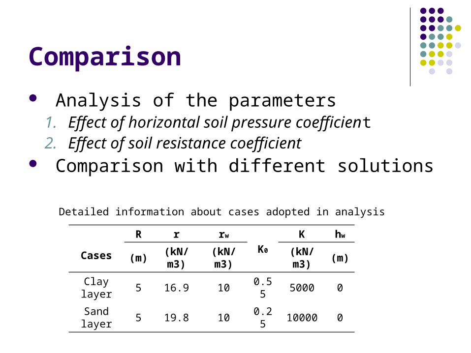
Comparison
Detailed information about cases adopted in analysis
Cases
R r rw
K0
K hw
(m) (kN/m3) (kN/m3) (kN/m3) (m)
Clay layer 5 16.9 10 0.55 5000 0
Sand layer 5 19.8 10 0.25 10000 0
Analysis of the parameters 1. Effect of horizontal soil pressure coefficient2. Effect of soil resistance coefficient
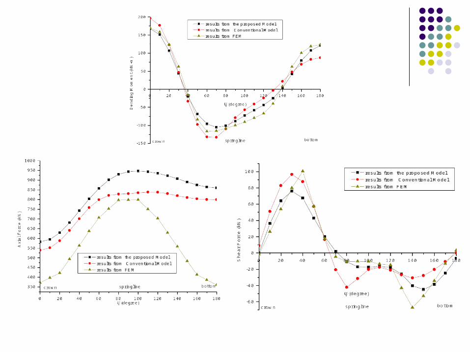
Comparison with different solutions

Effect of horizontal soil pressure coefficient
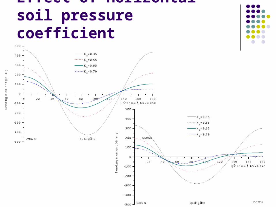
Effect of horizontal soil pressure coefficient
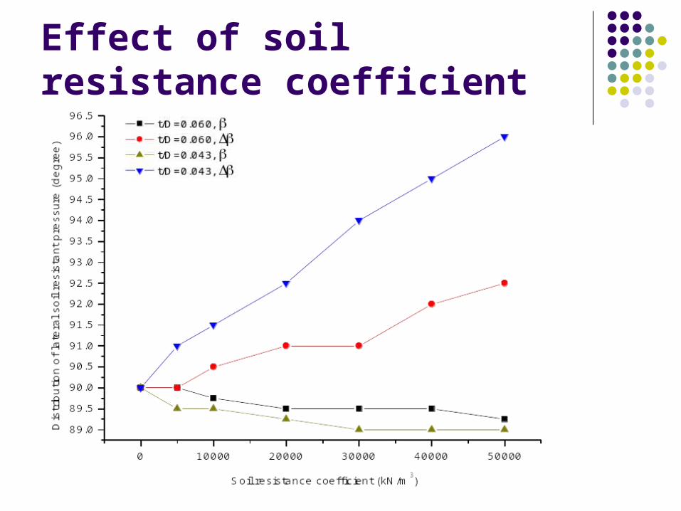
Effect of soil resistance coefficient

Effect of soil resistance coefficient
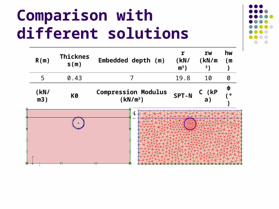
Comparison with different solutions
R(m)Thickness
(m)Embedded depth (m)
r(kN/m3)
rw(kN/m
3)
hw(m)
5 0.43 7 19.8 10 0
(kN/m3)
K0Compression Modulus
(kN/m3)SPT-N
C (kPa)
Φ(º)
20000 0.33 22000 18.7 1 38
x
y

CONCLUSION For a given soil resistance coefficient and a shallow embedded
depth, the distribution of soil resistant pressure is significantly effected by the value of horizontal soil pressure coefficient, and also the ratio of thickness versus diameter is a influencing factor.
For a given horizontal soil pressure coefficient and a shallow embedded depth, the distribution of soil resistant pressure is significantly effected by the value of soil resistance coefficient, and also the ratio of thickness versus diameter is a influencing factor.
The results predicted by the proposed analytical solution are compared with those of numerical simulation and the conventional model solution. The comparison indicates that the proposed solution agrees more reasonably, and it provides a new approach to better predict and make the preliminary design of shield tunnel lining

ThankYou!


