Download - antenna theory
What is an Antenna?
An antenna is defined by the IEEE as a “transmitting
or receiving system that is designed to radiate or receive
electromagnetic waves” . An antenna can be of any
shape or size. A list of some common types of antennas
is wire, aperture, microstrip, reflector, and arrays. Each
antenna configuration has a radiation pattern and design
parameters, in addition to their benefits and
drawbacks. In this section we will describe common
antenna types and their benefits and drawbacks. In
addition, we will discuss fundamental parameters of each
antenna configuration.
Types of Antennas
The “IEEE Standard of Terms for Antennas” has not
been updated since 1983 and the terms/definitions do
not describe many of the new antennas discovered
since, according to David V. Thiel of the Griffith
University .
He proposes antennas should be grouped by
categories. The following are the proposed grouping:
wire antennas (e.g., dipoles and loops), aperture
antennas (e.g., pyramidal horns), reflector antennas
(e.g., parabolic dish antennas), microstrip antennas
(e.g., patches), dielectric antennas (e.g., dielectric
resonant antennas), and active integrated antennas,
lens antennas (sphere), and antenna arrays.
Wire Antenna
A wire antenna is an antenna that is made of a
conductive wire. Wire antennas can come in different
configurations and some of these configurations are
dipoles, helix, and loop . Wire antennas can be seen
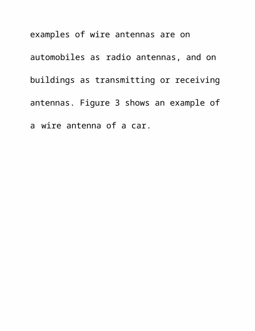
everywhere in daily lives. Some examples of wire
antennas are on automobiles as radio antennas, and on
buildings as transmitting or receiving antennas. Figure 3
shows an example of a wire antenna of a car.
Example of Wire Antenna
Wired antennas have an omni-directional radiation
pattern and the monopole antenna, a type of wire
antenna, comes standard with wireless routers.
Dipole Antenna
A dipole defined by the Merriam Webster Diction is
“a pair of equal and opposite electric charges or
magnetic poles of opposite signs separated especially by
a small distance” .
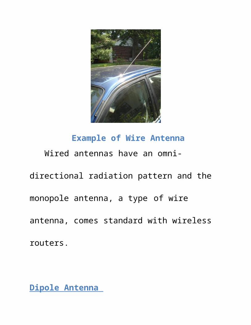
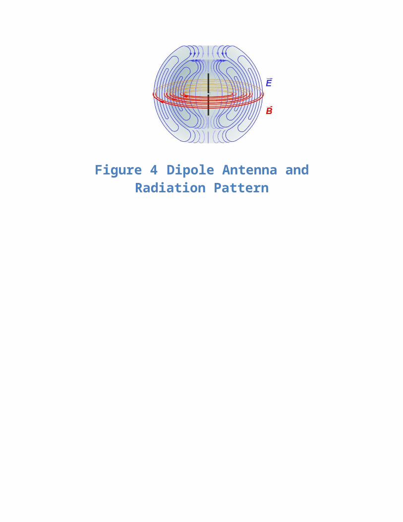
A simple design and radiation pattern of a
dipoleantenna can be shown as:-
Figure 4 Dipole Antenna and Radiation Pattern
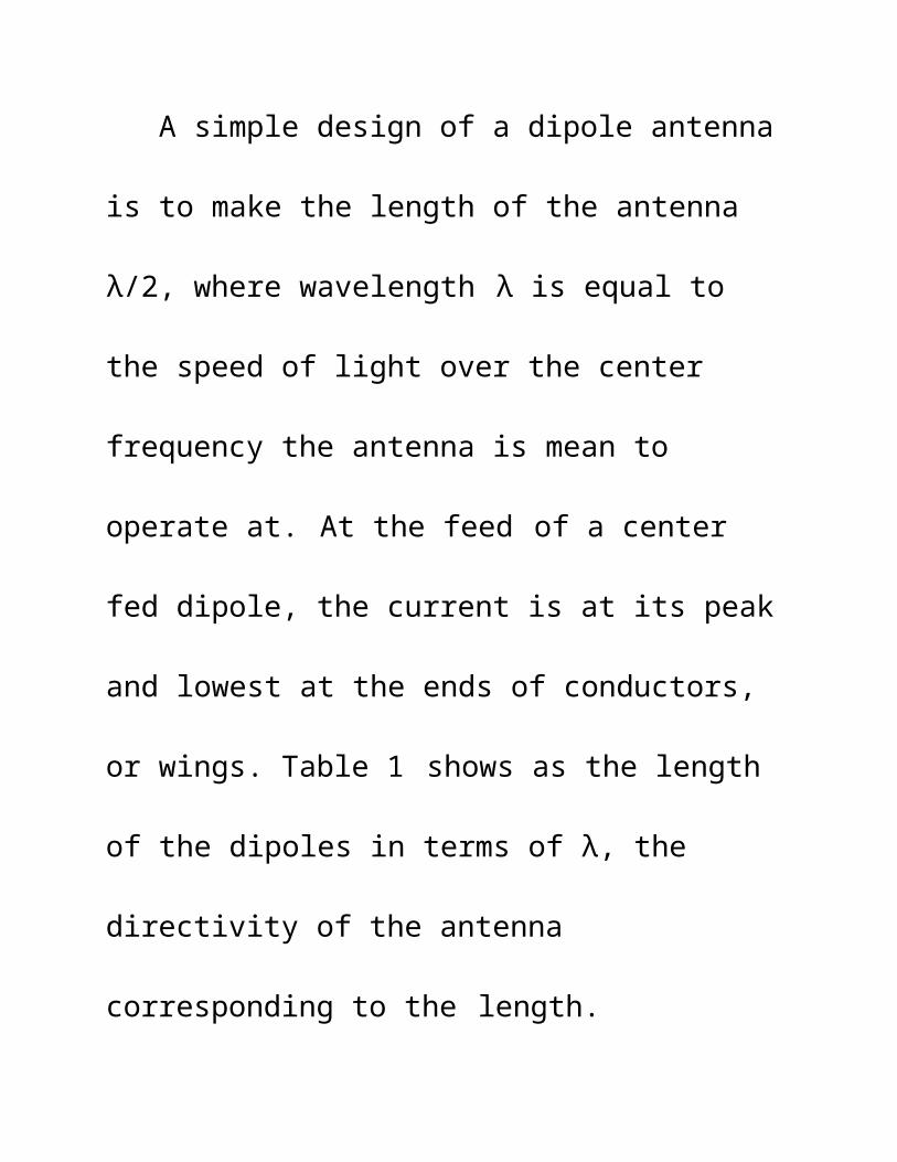
A simple design of a dipole antenna is to make the
length of the antenna λ/2, where wavelength λ is equal
to the speed of light over the center frequency the
antenna is mean to operate at. At the feed of a center
fed dipole, the current is at its peak and lowest at the
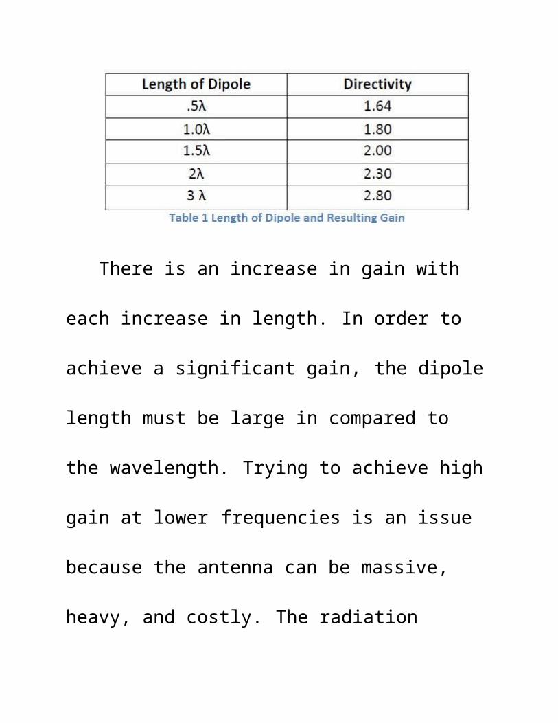
ends of conductors, or wings. Table 1 shows as the
length of the dipoles in terms of λ, the directivity of the
antenna corresponding to the length.
There is an increase in gain with each increase in
length. In order to achieve a significant gain, the dipole
length must be large in compared to the wavelength.
Trying to achieve high gain at lower frequencies is an
issue because the antenna can be massive, heavy, and
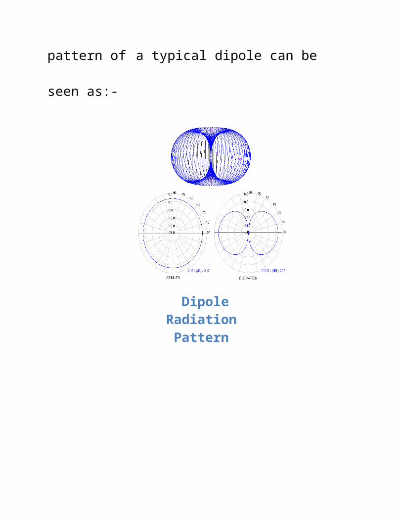
costly. The radiation pattern of a typical dipole can be
seen as:-
Dipole Radiation Pattern
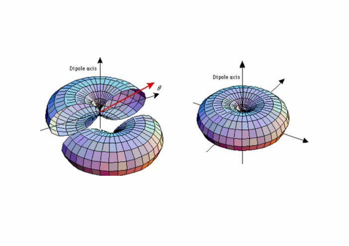
The radiation pattern of a dipole is in all directions.
In addition, the radiation pattern looks similar to that of
a donut. There are many different variations of dipole
antennas and some common types are biconical,
bowtie, and blade dipoles.
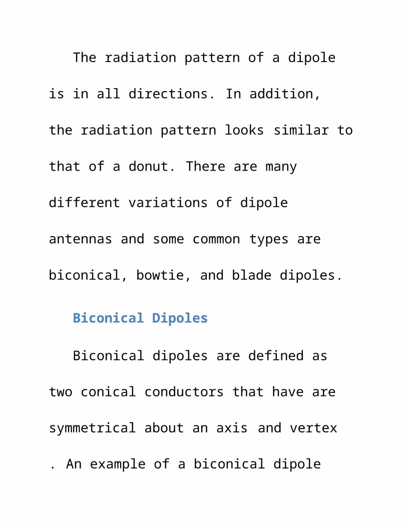
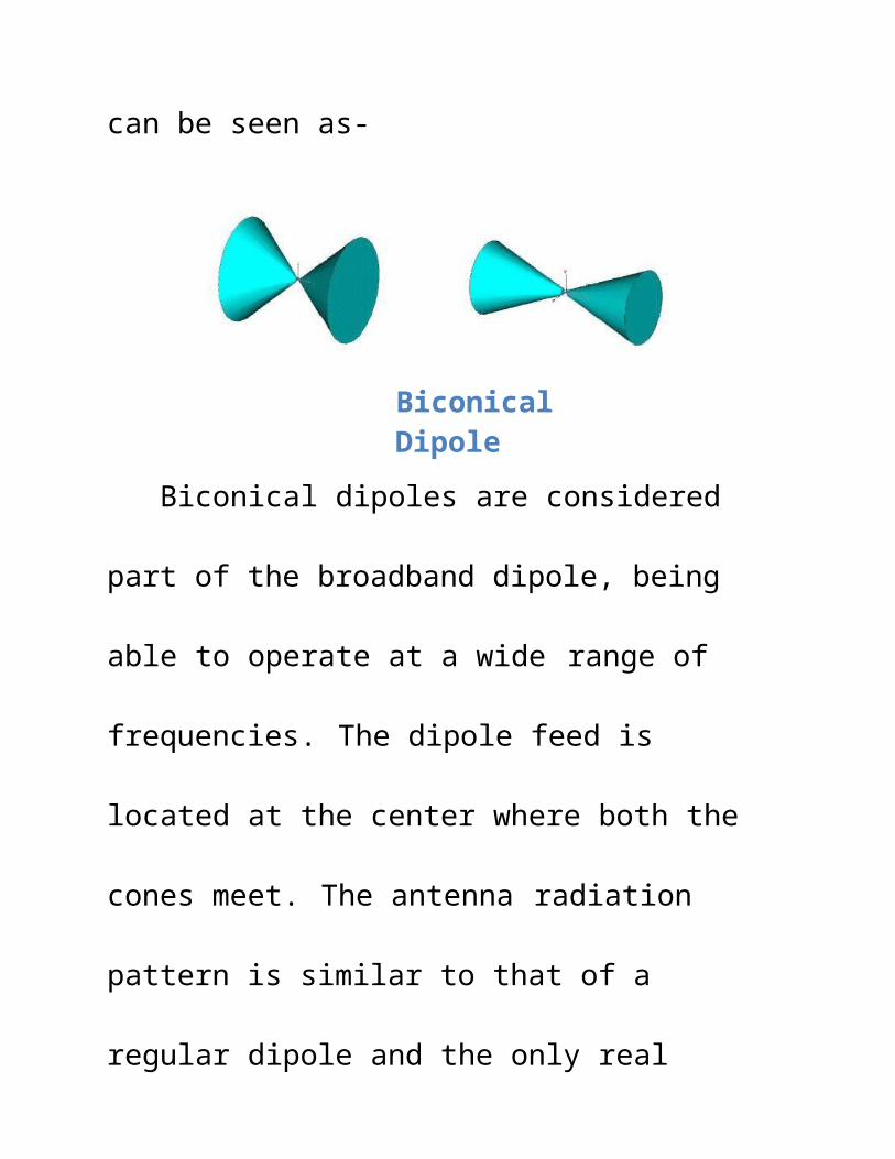
Biconical Dipoles
Biconical dipoles are defined as two conical
conductors that have are symmetrical about an axis
and vertex . An example of a biconical dipole can be
seen as-
Biconical Dipole
Biconical dipoles are considered part of the
broadband dipole, being able to operate at a wide range
of frequencies. The dipole feed is located at the center
where both the cones meet. The antenna radiation
pattern is similar to that of a regular dipole and the only
real difference is the allowable bandwidth of this
antenna is considerably higher than the dipole and can
commonly achieve bandwidths of four to one.
Sometimes these cones are made out of a solid
metal conductor which can be heavy and costly.
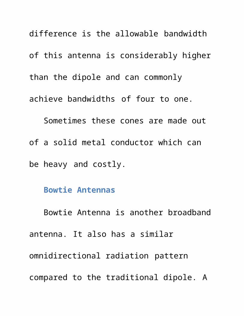
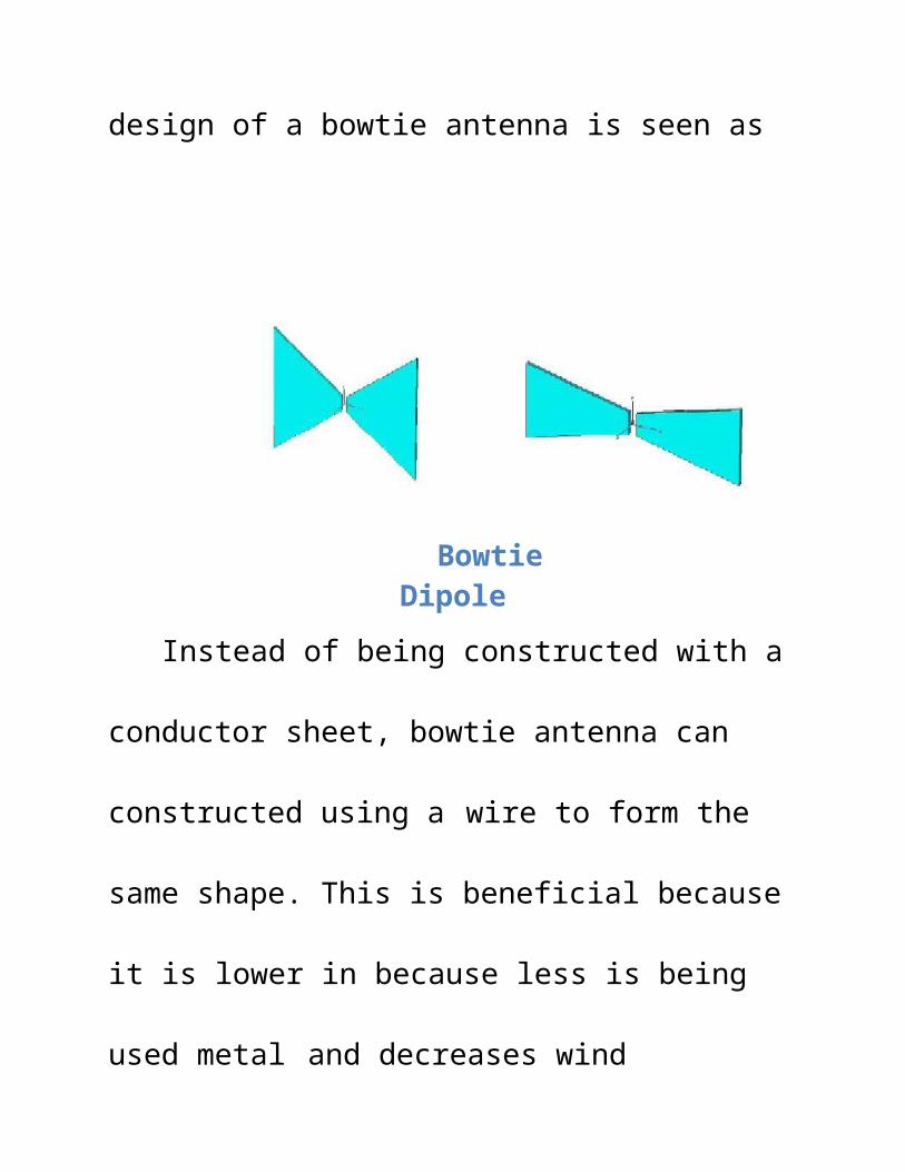
Bowtie Antennas
Bowtie Antenna is another broadband antenna. It
also has a similar omnidirectional radiation pattern
compared to the traditional dipole. A design of a bowtie
antenna is seen as
Bowtie Dipole
Instead of being constructed with a conductor
sheet, bowtie antenna can constructed using a wire to
form the same shape. This is beneficial because it is
lower in because less is being used metal and decreases
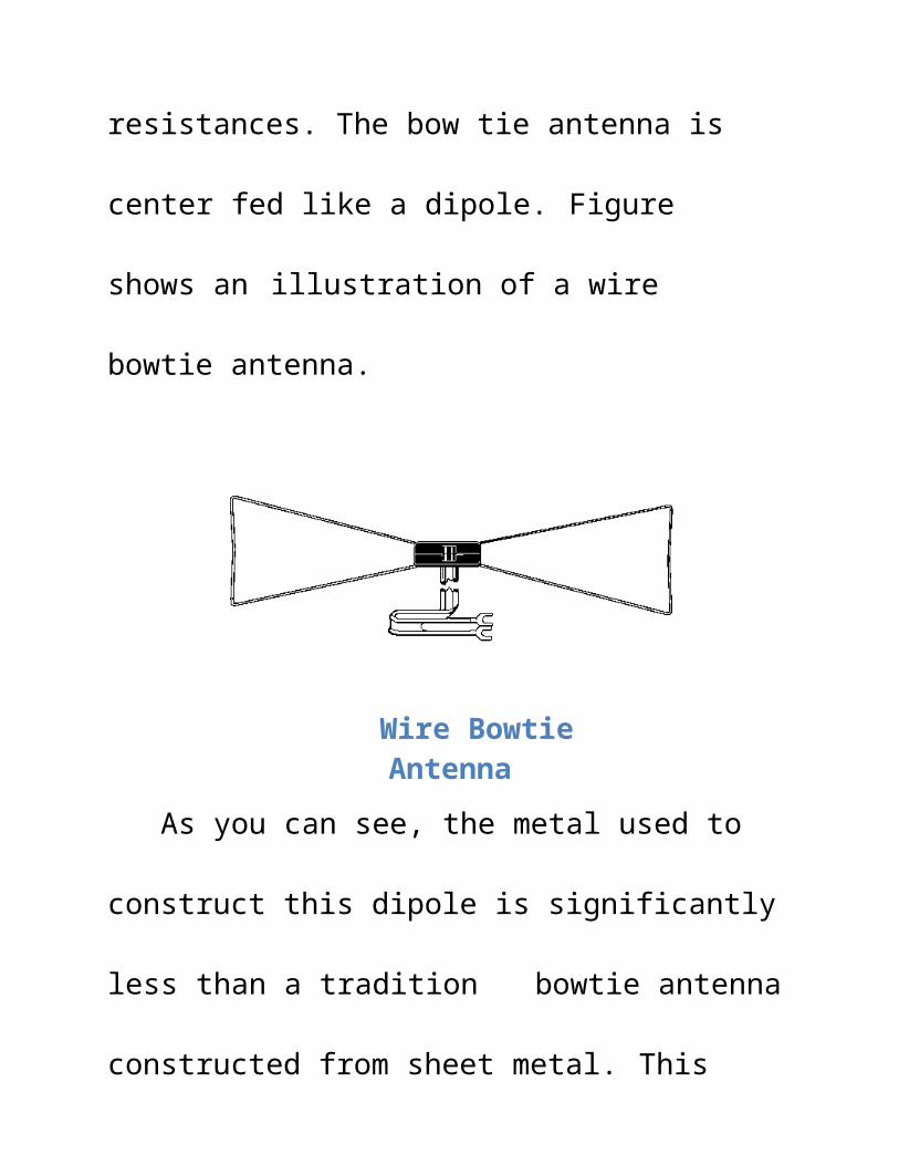
wind resistances. The bow tie antenna is center fed like
a dipole. Figure shows an illustration of a wire bowtie
antenna.
Wire Bowtie Antenna
As you can see, the metal used to construct this
dipole is significantly less than a tradition bowtie
antenna constructed from sheet metal. This method will
lower production cost and decrease the weight of
antenna.
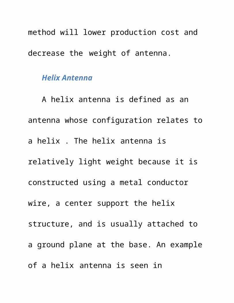
Helix Antenna
A helix antenna is defined as an antenna whose
configuration relates to a helix . The helix antenna is
relatively light weight because it is constructed using a
metal conductor wire, a center support the helix
structure, and is usually attached to a ground plane at
the base. An example of a helix antenna is seen in
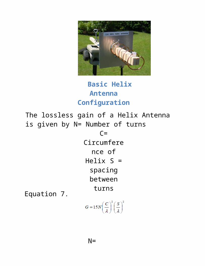
Basic Helix Antenna Configuration
The lossless gain of a Helix Antenna is given by N= Number of turns
C= Circumference
of Helix S = spacing
between turnsEquation 7.
N= Number of turns C=Circumference of Helix S = spacing between turns
The gain is dependent of the number of turns, the
circumference of the helix, the spacing between turns,
and the wavelength. Designers can increase the gain of
the antenna by adding additional turns which will
increase the length of the antenna. Another key
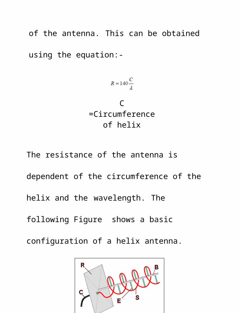
characteristic is the input impedance of the antenna.
This can be obtained using the equation:-
C =Circumference of helix
The resistance of the antenna is dependent of the
circumference of the helix and the wavelength. The
following Figure shows a basic configuration of a helix
antenna.
Figure:-Basic Helix Antenna Configuration
The coaxial cable is connected to the feed is label as
C, R is the reflector base, B is the center support, E is the
support for the helix, and S is the wire of the helix
antenna that is radiating or receiving electromagnetic
waves. Other design parameters that needs to be
consider when designing a helix antenna are the pitch
angle (arctan (S/ pi*D)), the total length of the antenna
(NS), and total length of wire (N*Length of one turn)
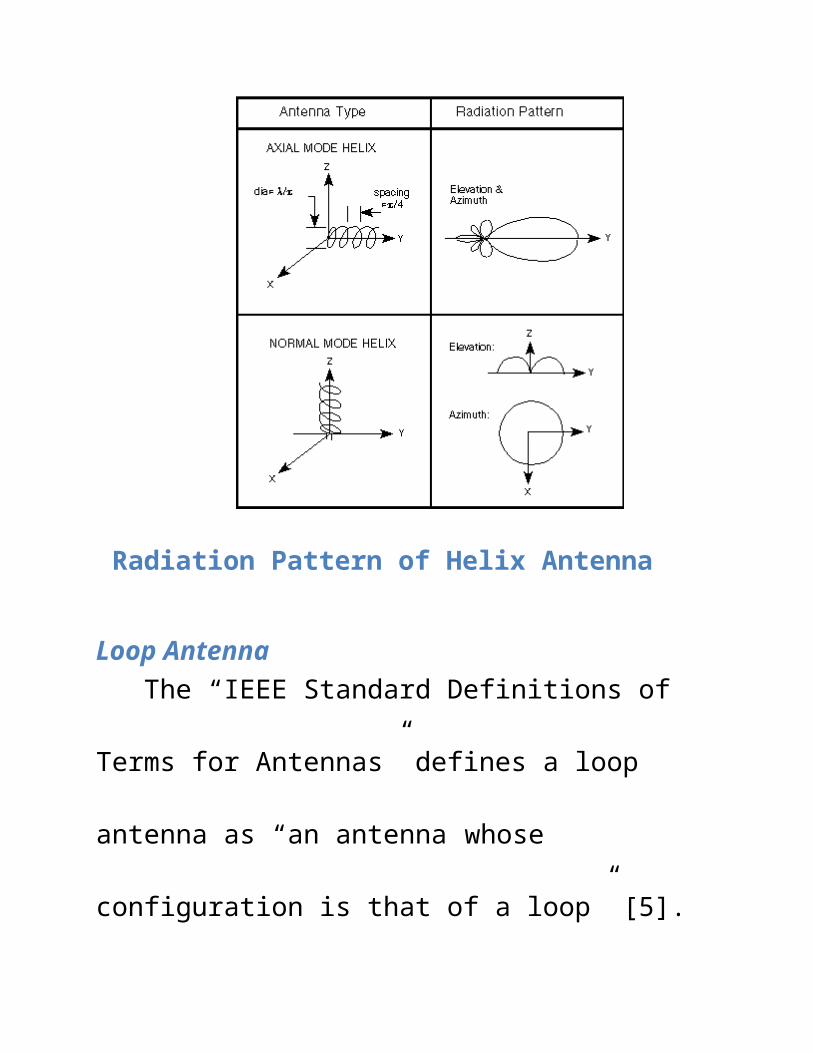
There are two operational modes for a helix
antenna: axial mode, and normal mode. In normal
mode the spacing between helixes and the diameter of
the helixes are small in comparison with the
wavelength. The radiation pattern is along the helical
direction and it is similar to that of a dipole. In axial
mode, the antenna functions like a directional antenna
and the spacing between elements is λ/4. The antenna
radiates at the top of the helix along the axis of the
antenna. The radiation pattern of both operation modes
can be seen in
Radiation Pattern of Helix Antenna
Loop AntennaThe “IEEE Standard Definitions of Terms for
Antennas” defines a loop antenna as “an antenna
whose configuration is that of a loop” [5]. This loop can
be in the shape of a square, rectangle, circle trip, and
many other geometric shapes. There are two different
categories to loop antennas: electrically small or
electrically large . Electrically small antennas are defined
as antennas that loop length is less than one-tenth of
wavelength. Wavelength, λ, is the ratio of the speed of
light over the frequency at which the antenna is
designed to operate at. Small loop antennas are
sometimes called the magnetic loop because it acts like
an inductor.
Electrically large loop antennas are defined as
antennas that have a loop length of approximately λ.
Figure shows examples of loop antennas.
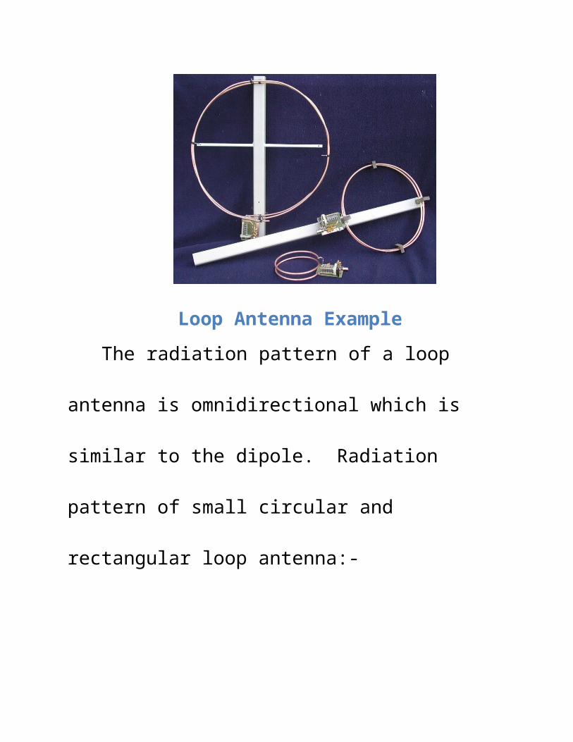
Loop Antenna Example
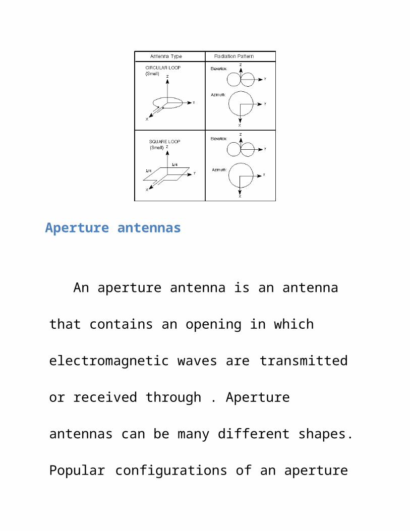
The radiation pattern of a loop antenna is
omnidirectional which is similar to the dipole. Radiation
pattern of small circular and rectangular loop antenna:-
Aperture antennas
An aperture antenna is an antenna that contains an
opening in which electromagnetic waves are transmitted
or received through . Aperture antennas can be many
different shapes. Popular configurations of an aperture
antenna are waveguides and horns . Aperture antennas
are used widely in aircrafts because the can be covered
with a dielectric. This dielectric protects the antenna
from the environments that an aircraft is exposed to. A
waveguide is an antenna that guides an electromagnetic
wave. It consists of a conductive wall that is hollow in
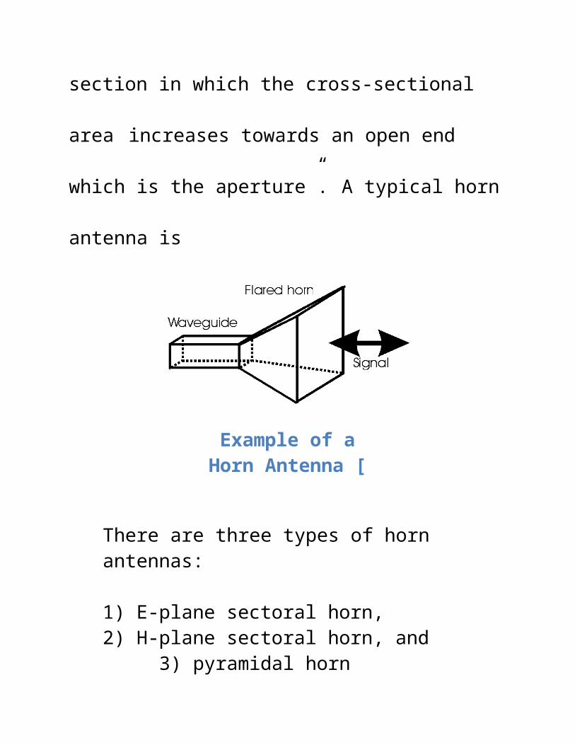
the inside for the wave to travel. A horn antenna is “an
antenna consisting of a waveguide section in which the
cross-sectional area increases towards an open end
which is the aperture”. A typical horn antenna is
Example of a Horn Antenna [
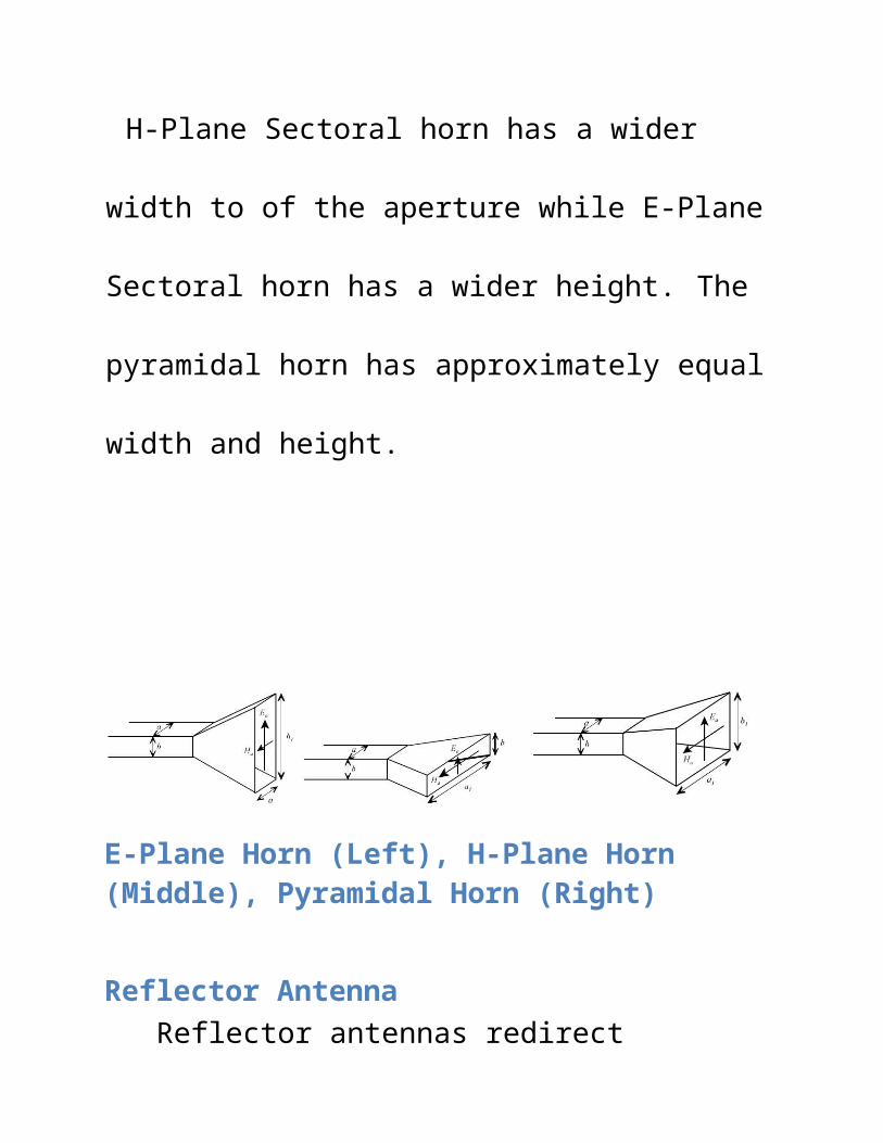
There are three types of horn antennas: 1) E-plane sectoral horn, 2) H-plane sectoral horn, and
3) pyramidal horn
H-Plane Sectoral horn has a wider width to of the
aperture while E-Plane Sectoral horn has a wider
height. The pyramidal horn has approximately equal
width and height.
E-Plane Horn (Left), H-Plane Horn (Middle), Pyramidal Horn (Right)
Reflector AntennaReflector antennas redirect electromagnetics and
refocus it in a certain direction. This type of antenna is
commonly used for space crafts for long distance
communication . Several common types of reflector
antennas are the plane reflector, the corner reflector,
and the parabolic reflector. A plane reflector is flat
reflector made of a conductor. The electromagnetic
waves redirects concept can be compared to sunlight
hitting a mirror.
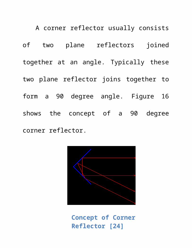
A corner reflector usually consists of two plane
reflectors joined together at an angle. Typically these
two plane reflector joins together to form a 90 degree
angle. Figure 16 shows the concept of a 90 degree
corner reflector.
Concept of Corner Reflector [24]
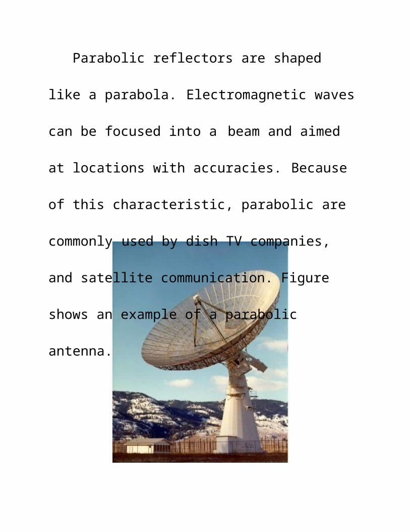
Parabolic reflectors are shaped like a parabola.
Electromagnetic waves can be focused into a beam and
aimed at locations with accuracies. Because of this
characteristic, parabolic are commonly used by dish TV
companies, and satellite communication. Figure shows
an example of a parabolic antenna.
The losses gain or directivity of a reflector antenna
can be found by knowing the wavelength and the cross-
sectional aperture.
The following Equation is the equation for the
directive for a reflector antenna.
Directivity of a reflector antenna
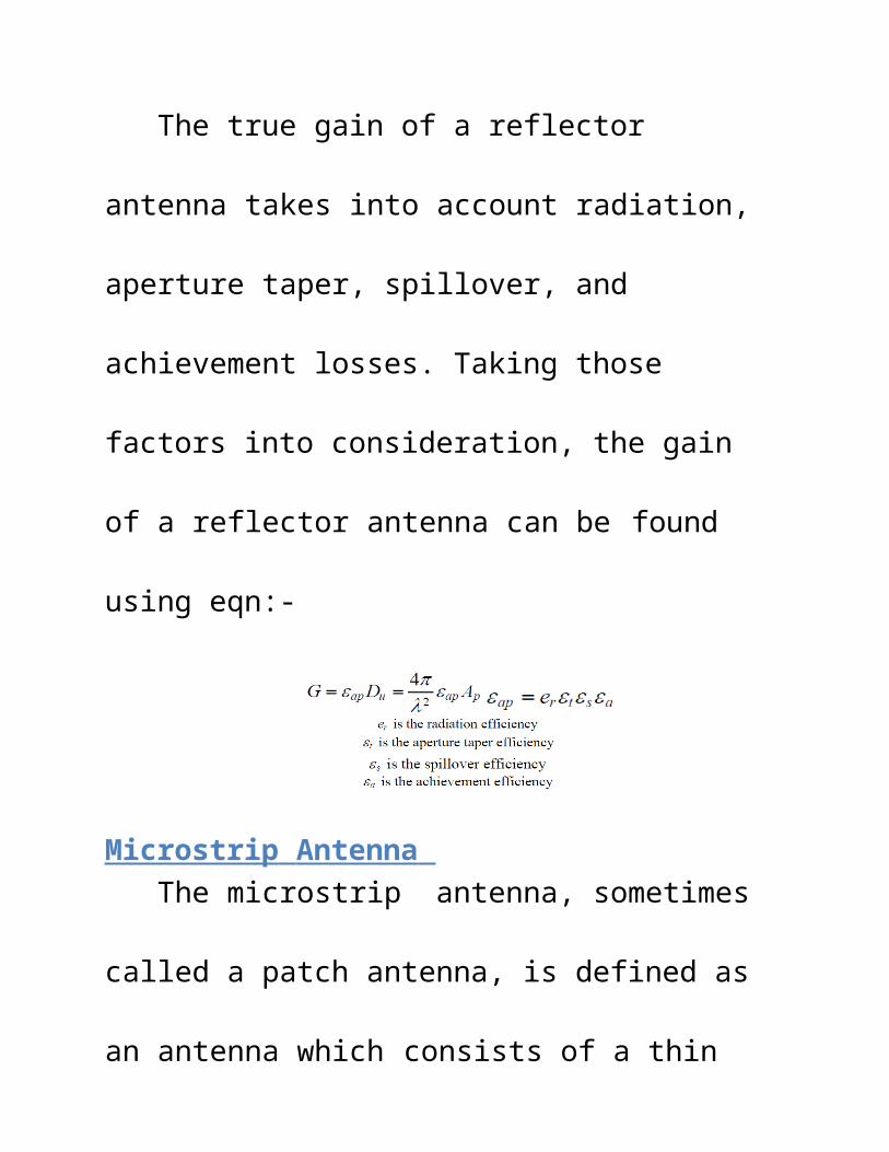
The true gain of a reflector antenna takes into
account radiation, aperture taper, spillover, and
achievement losses. Taking those factors into
consideration, the gain of a reflector antenna can be
found using eqn:-
Microstrip Antenna The microstrip antenna, sometimes called a patch
antenna, is defined as an antenna which consists of a
thin metallic conductor bonded to a thin grounded
dielectric substrate . Microstrip antennas are low
profile, small in volume, and have low production cost .
The feed can be connected directly to the conductor on
the same substrate. The antenna design can be printed
onto ceramic substrate which eliminates the need for
an adhesive to bond the conductor to the substrate.
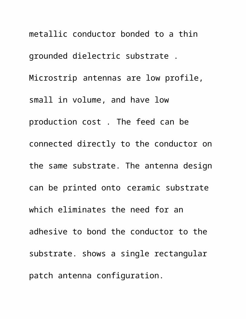
shows a single rectangular patch antenna configuration.
Basic Patch Antenna Design
The patch antenna can operate from the ranges from 1GHz to 6GHz. At lower frequency the antenna can be
large in size and may not be practical.
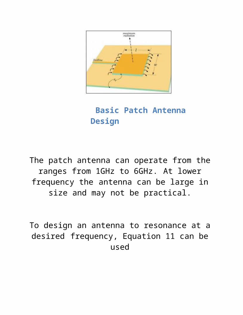
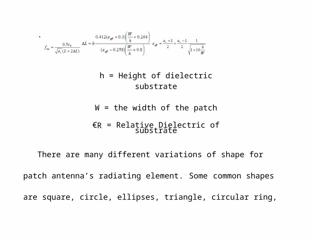
To design an antenna to resonance at a desired frequency, Equation 11 can be used
.
h = Height of dielectric substrate
W = the width of the patch
€R = Relative Dielectric of substrate
There are many different variations of shape for patch antenna’s radiating
element. Some common shapes are square, circle, ellipses, triangle, circular ring,
and dipole. The more commonly used shapes are square, rectangle, dipole, and
circle are used because they are easier to analyze than other shapes.
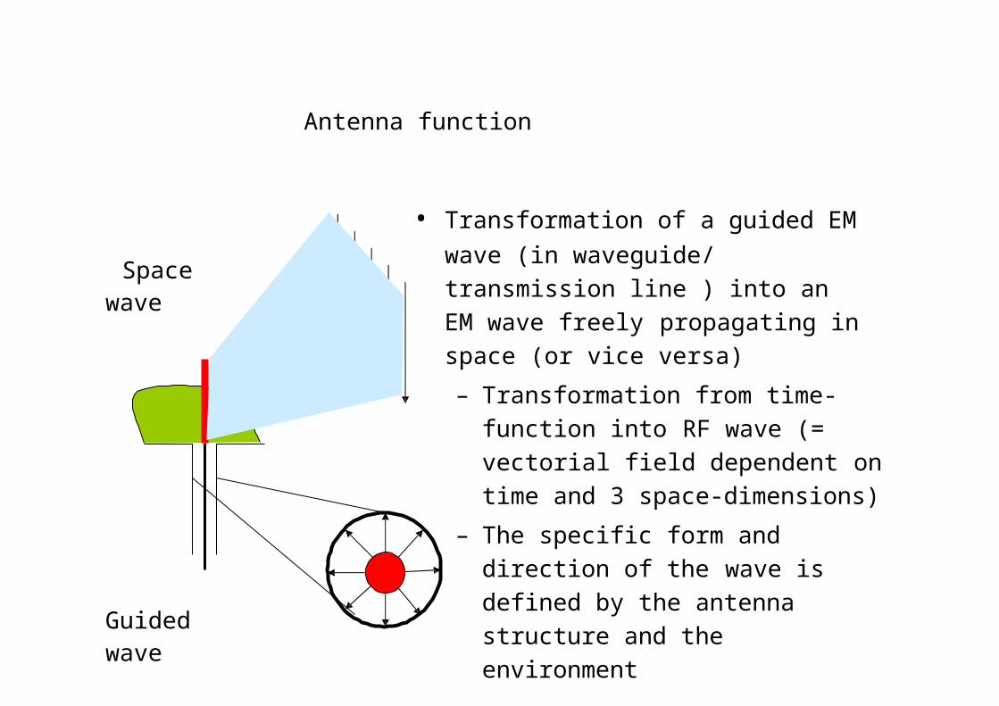
Antenna function
Space wave
Guided wave
• Transformation of a guided EM wave (in waveguide/ transmission line ) into an EM wave freely propagating in space (or vice versa)
– Transformation from time-function into RF wave (= vectorial field dependent on time and 3 space-dimensions)
– The specific form and direction of the wave is defined by the antenna structure and the environment
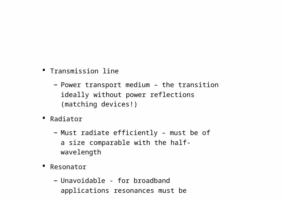
• Transmission line
– Power transport medium – the transition ideally without power reflections (matching devices!)
• Radiator
– Must radiate efficiently – must be of a size comparable with the half-wavelength
• Resonator
– Unavoidable - for broadband applications resonances must be attenuated
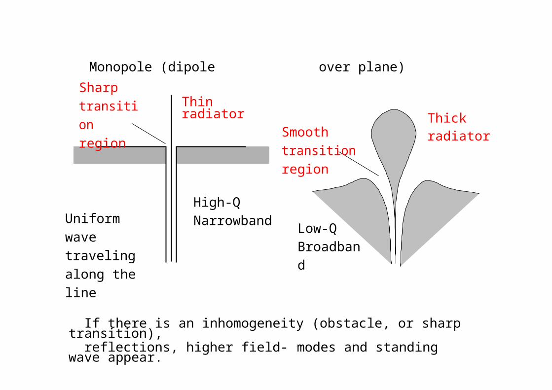
Monopole (dipole over plane)
Sharptransition region
Uniform wave traveling along the line
Thin radiator
High-Q Narrowband
Smooth transition region
Low-Q Broadband
Thick radiator
If there is an inhomogeneity (obstacle, or sharp transition), reflections, higher field- modes and standing wave appear.
With standing wave, the energy is stored in, and oscillates from electric energy to magnetic one and back. This can be modeled as a resonating LC circuit with
Q = (energy stored per cycle) / (energy lost per cycle)
Dipole, Slot & INF antennas
• Slot antenna: a slot is cut from a large (relative to the slot length) metal plate.
• The center conductor of the feeding coaxial cable is connected to one side of the slot, and the outside conductor of the cable - to the other side of the slot.
– The slot length is some (/2) for the slot antenna and (/4) long for the INF antenna.
• The INF and the slot antennas behave similarly.• The slot antenna can be considered as a loaded version of
the INF antenna. The load is a quarter-wavelength stub, i.e. a narrowband device.
• When the feed point is moved to the short-circuited end of the slot (or INF) antenna, the impedance decreases. When it is moved to the slot center (or open end of the INF antenna), the impedance increases
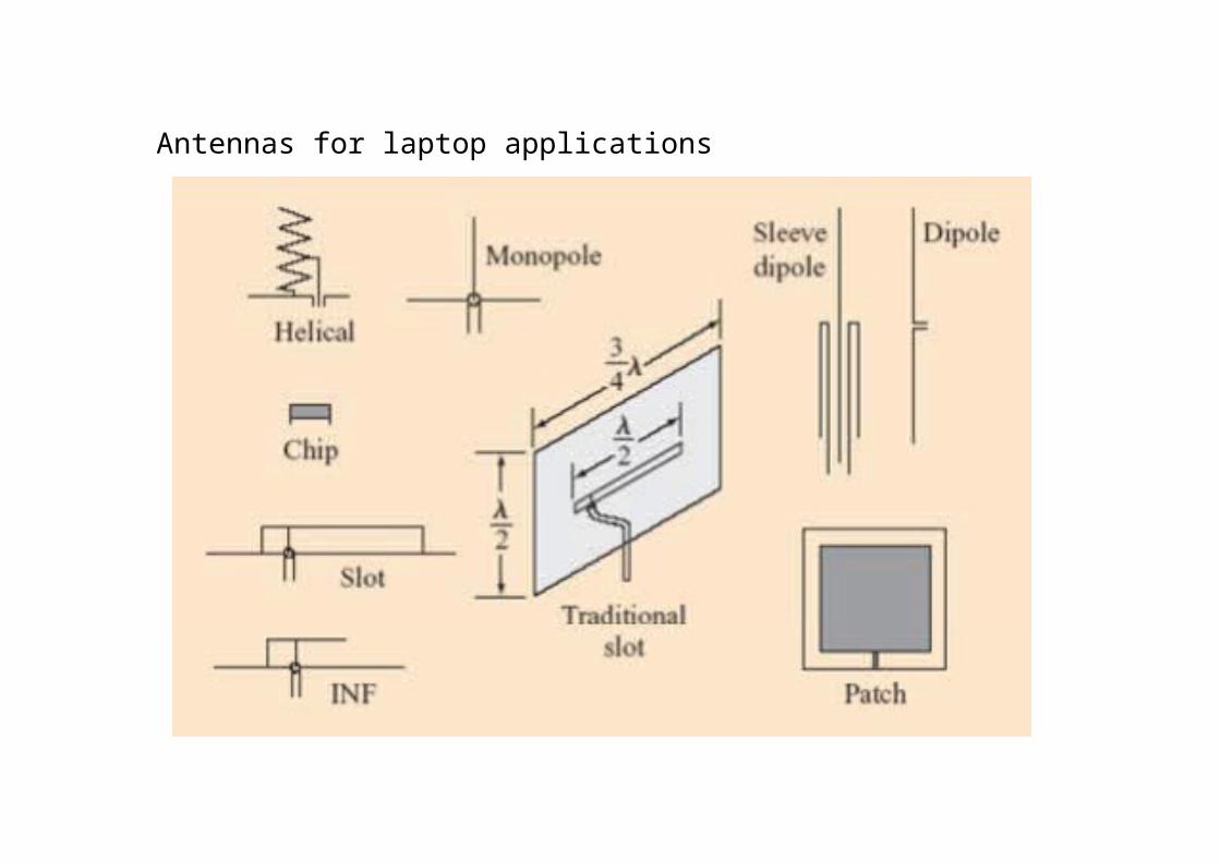
Antennas for laptop applications
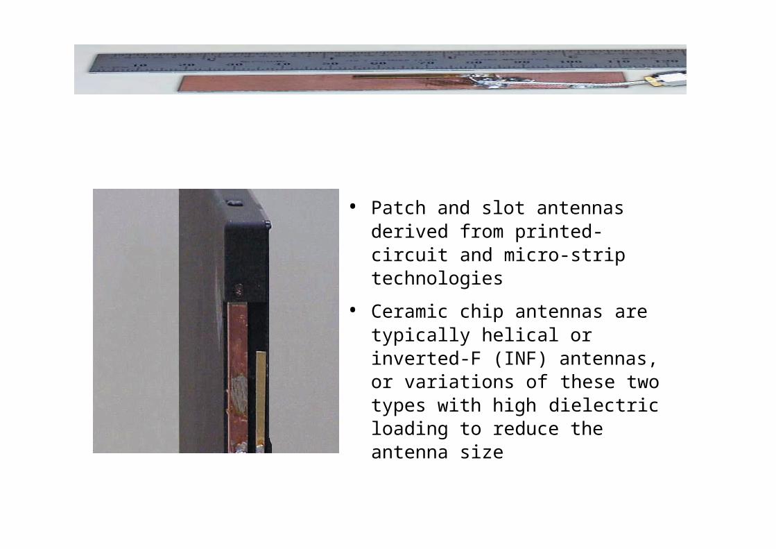
• Patch and slot antennas derived from printed-circuit and micro-strip technologies
• Ceramic chip antennas are typically helical or inverted-F (INF) antennas, or variations of these two types with high dielectric loading to reduce the antenna size

• Patch and slot antennas are
– Cheap and easy to fabricate and to mount
– Suited for integration
– Light and mechanically robust
– Have low cross-polarization
– Low-profile - widely used in antenna arrays
spacec–rafts, satellites, missiles, cars and other mobile applications
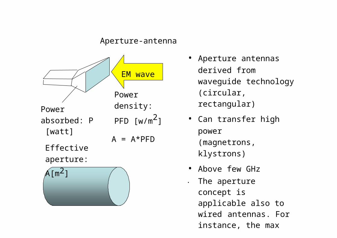
Aperture-antenna
• Aperture antennas
Powerabsorbed: P
[watt]
Effective aperture:
A[m2]
EM wave
Power density:
PFD [w/m2]
A = A*PFD
derived from waveguide technology (circular, rectangular)
• Can transfer high power (magnetrons, klystrons)
• Above few GHz• The aperture concept is
applicable also to wired antennas. For instance, the max effective aperture of linear /2 wavelength dipole antenna is 2/8
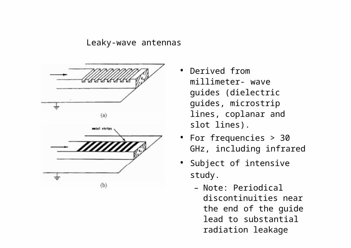
Leaky-wave antennas
• Derived from millimeter- wave guides (dielectric guides, microstrip lines, coplanar and slot lines).
• For frequencies > 30 GHz, including infrared
• Subject of intensive study.– Note: Periodical
discontinuities near the end of the guide lead to substantial radiation leakage (radiation from the dielectric surface).
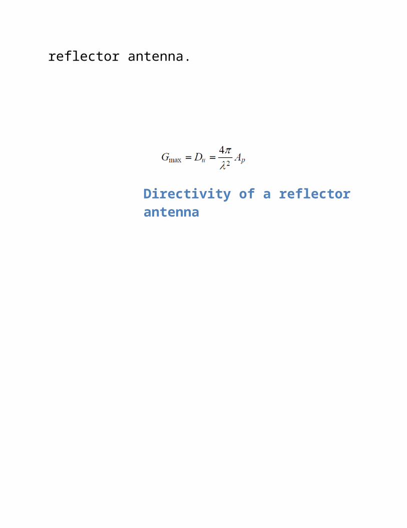
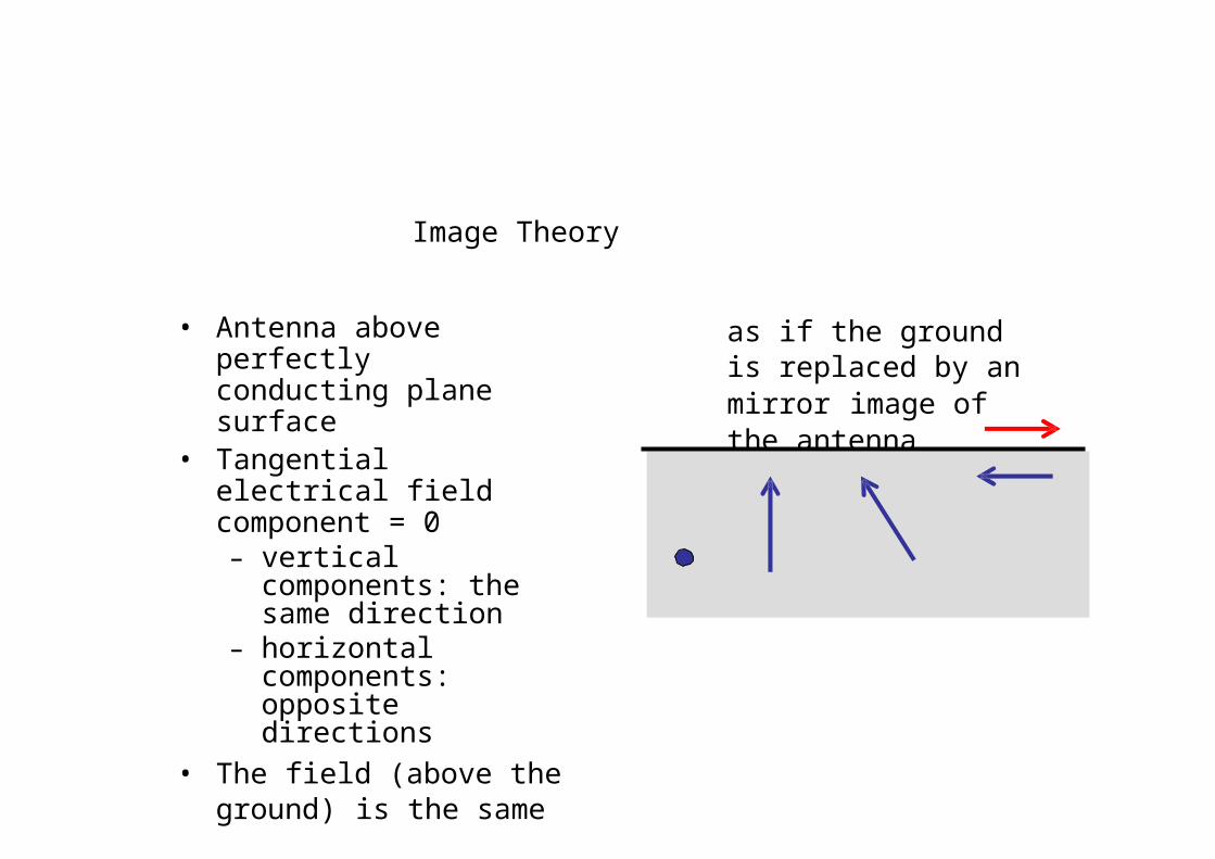
Image Theory
• Antenna above perfectly conducting plane surface
• Tangential electrical field component = 0– vertical components:
the same direction– horizontal
components: opposite directions
• The field (above the ground) is the same as if the ground is replaced by an mirror image of the antenna
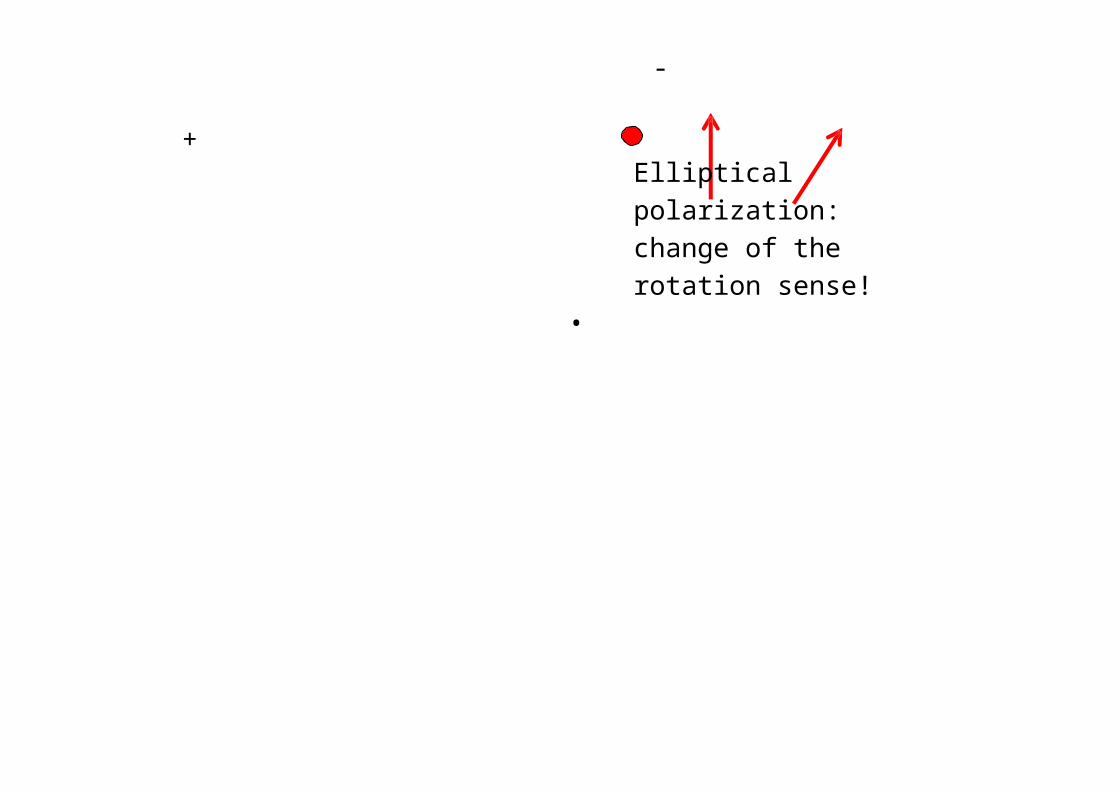
+
-
Elliptical polarization: change of the rotation sense!
•
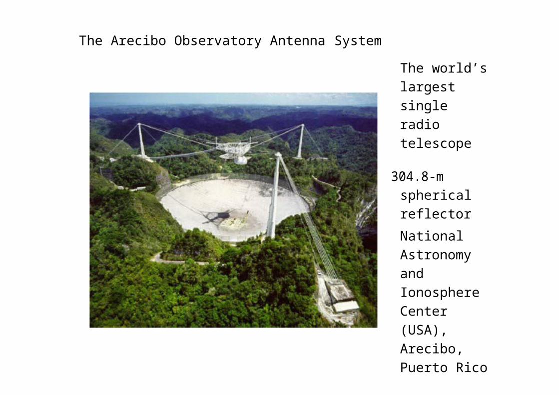
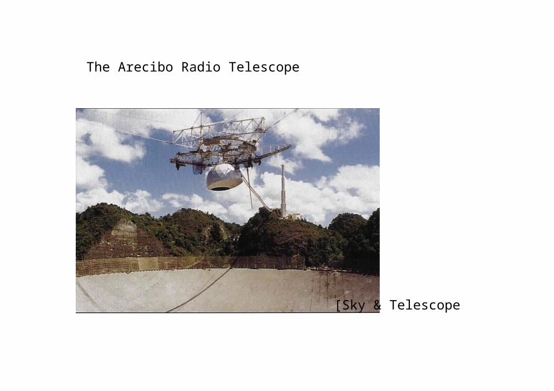
The Arecibo Observatory Antenna System
The world’s largest single radio telescope
304.8-mspherical reflector
National Astronomy and Ionosphere Center (USA), Arecibo, Puerto Rico
The Arecibo Radio Telescope
[Sky & Telescope
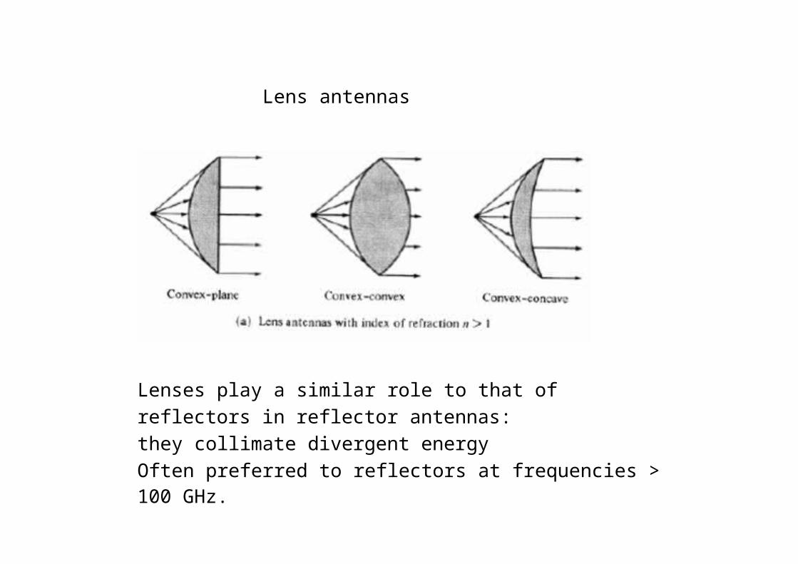
Lens antennas
Lenses play a similar role to that of reflectors in reflector antennas: they collimate divergent energyOften preferred to reflectors at frequencies > 100 GHz.
Radiation pattern
• The radiation pattern of antenna is a representation (pictorial or mathematical) of the distribution of the power out-flowing (radiated) from the antenna (in the case of transmitting antenna), or inflowing (received) to the antenna (in the case of receiving antenna) as a function of direction angles from the antenna
• Antenna radiation pattern (antenna pattern):– is defined for large distances from the antenna,
where the spatial (angular) distribution of the radiated power does not depend on the distance from the radiation source
– is independent on the power flow direction: it is the same when the antenna is used to transmit and when it is used to receive radio waves
– is usually different for different frequencies and different polarizations of radio wave radiated/ received
Power- orfield-strength meter
Turntable
ant
Generator
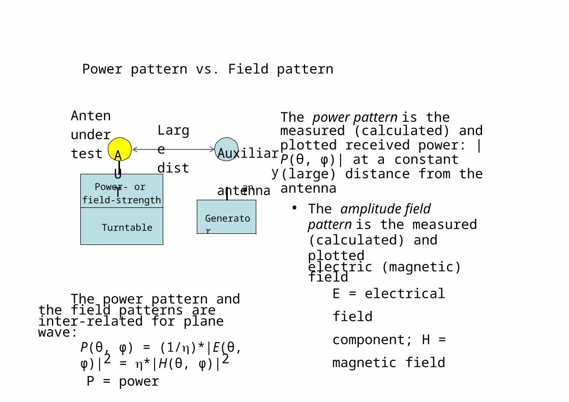
Power pattern vs. Field pattern
Anten under test
AUT
Large dist Auxiliary
antenna
The power pattern is the measured (calculated) and plotted received power: |P(θ, ϕ)| at a constant (large) distance from the antenna
• The amplitude field pattern is the measured (calculated) and plottedelectric (magnetic) field
The power pattern and the field patterns are inter-related for plane wave:
P(θ, ϕ) = (1/)*|E(θ, ϕ)|2 = *|H(θ, ϕ)|2
P = powerE = electrical field
component; H = magnetic
field component vector
= 377 ohm (free-space, plane wave impedance)
intensity, |E(θ, ϕ)| or|H(θ, ϕ)| at a constant (large) distance from theantenna

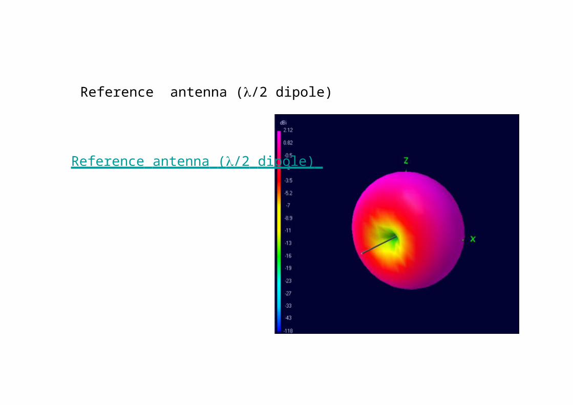
Reference antenna (/2 dipole)
Reference antenna ( /2 dipole)

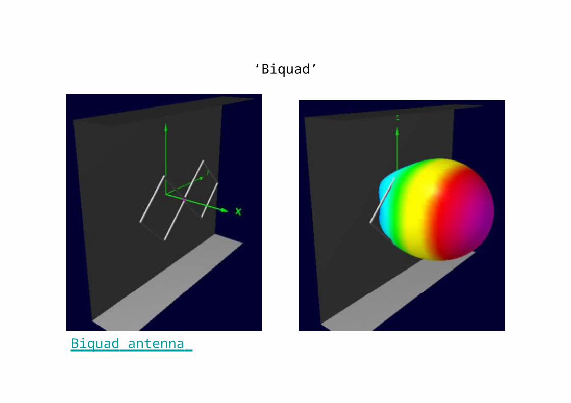
‘Biquad’
Biquad antenna
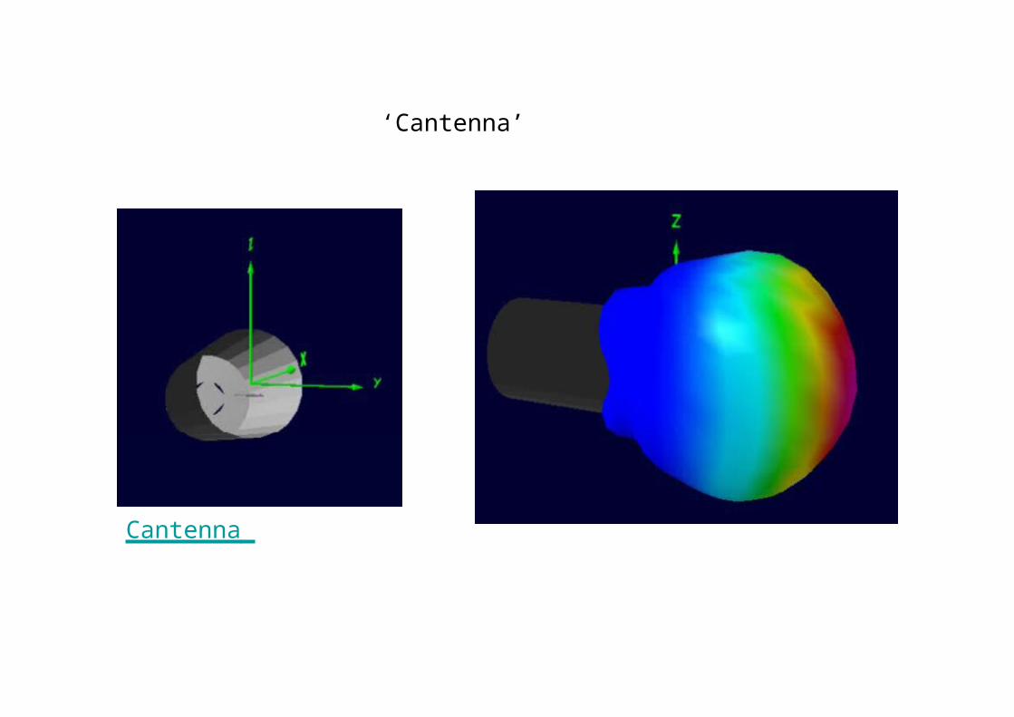
‘Cantenna’
Cantenna
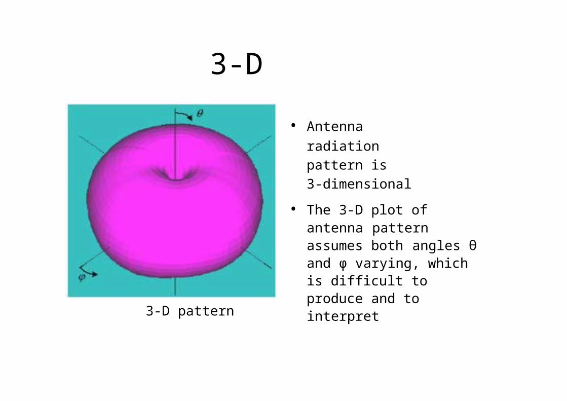
3-D pattern
3-D pattern
• Antenna radiation pattern is3-dimensional
• The 3-D plot of antenna pattern assumes both angles θ and ϕ varying, which is difficult to produce and to interpret
2-D pattern
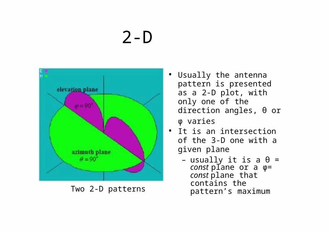
Two 2-D patterns
• Usually the antenna pattern is presented as a 2-D plot, with only one of the direction angles, θ orϕ varies
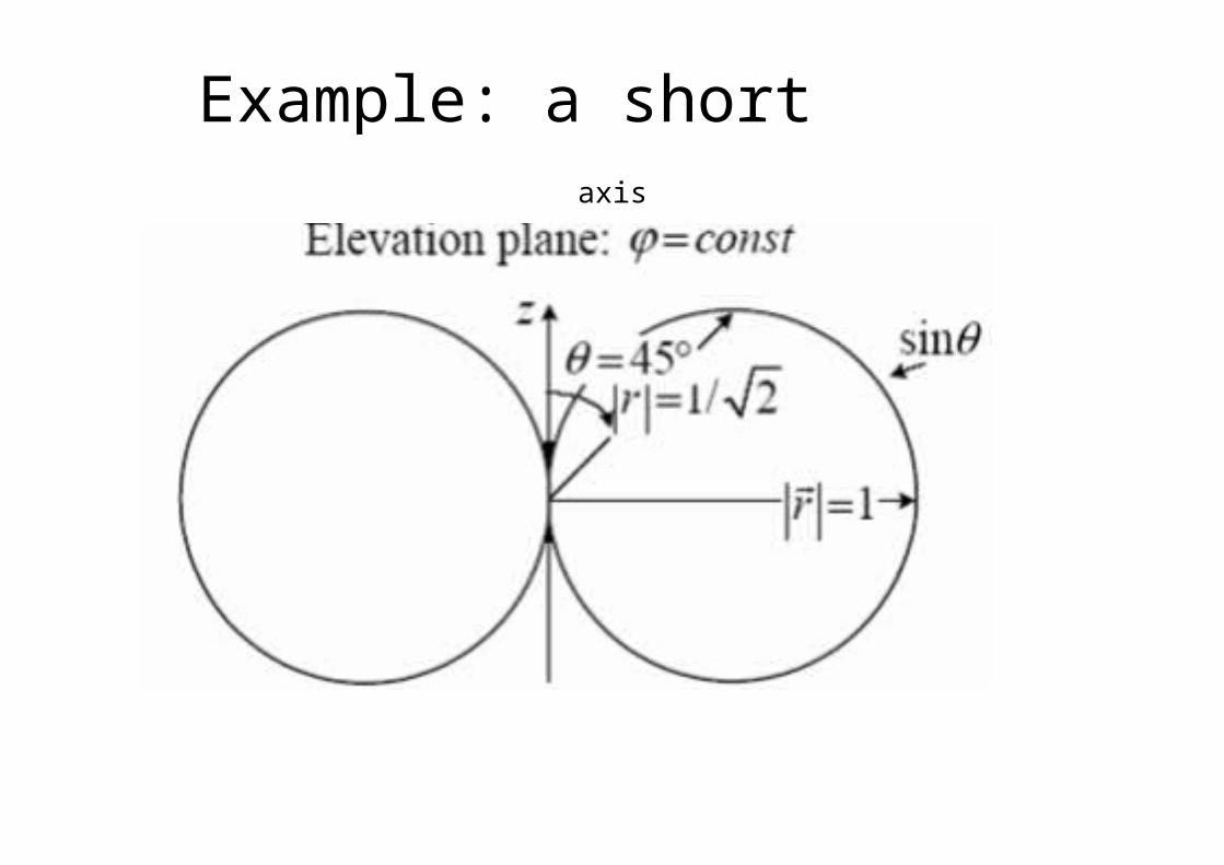
• It is an intersection of the 3-D one with a given plane– usually it is a θ = const
plane or a ϕ= const plane that contains the pattern’s maximum
Example: a short dipole on z-axis
Principal patterns• Principal patterns are the 2-D patterns of linearly polarized
antennas, measured in 2 planes
1. the E-plane: a plane parallel to the E vector and containing the direction of maximum radiation, and
2. the H-plane: a plane parallel to the H vector, orthogonal to the E-plane, and containing the direction of maximum radiation
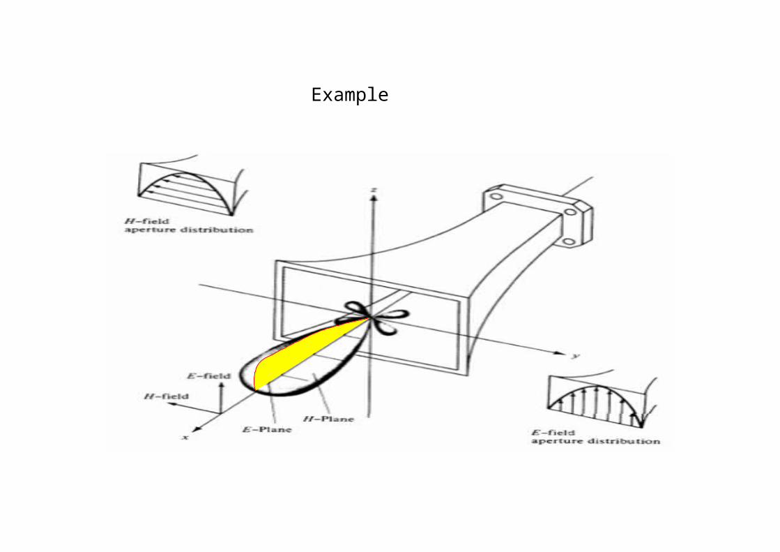
Example
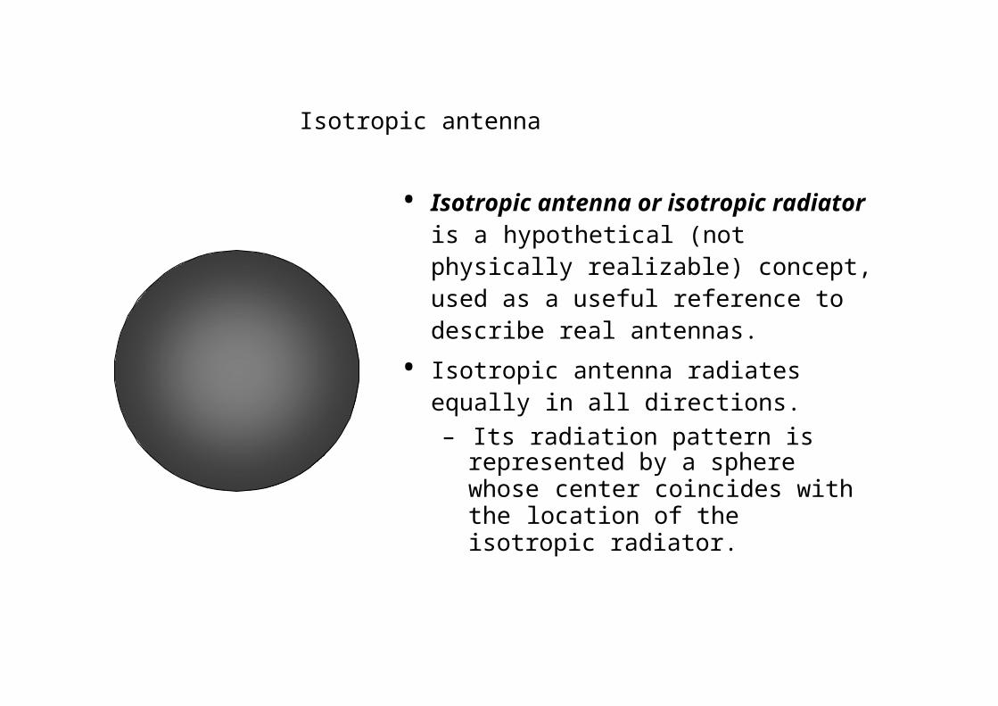
Isotropic antenna
• Isotropic antenna or isotropic radiator is a hypothetical (not physically realizable) concept, used as a useful reference to describe real antennas.
• Isotropic antenna radiates equally in all directions.– Its radiation pattern is represented by
a sphere whose center coincides with the location of the isotropic radiator.
Directional antenna
• Directional antenna is an antenna, which radiates (or receives) much more power in (or from) some directions than in (or from) others.
– Note: Usually, this term is applied to antennas whose directivity is much higher than that of a half-wavelength dipole.
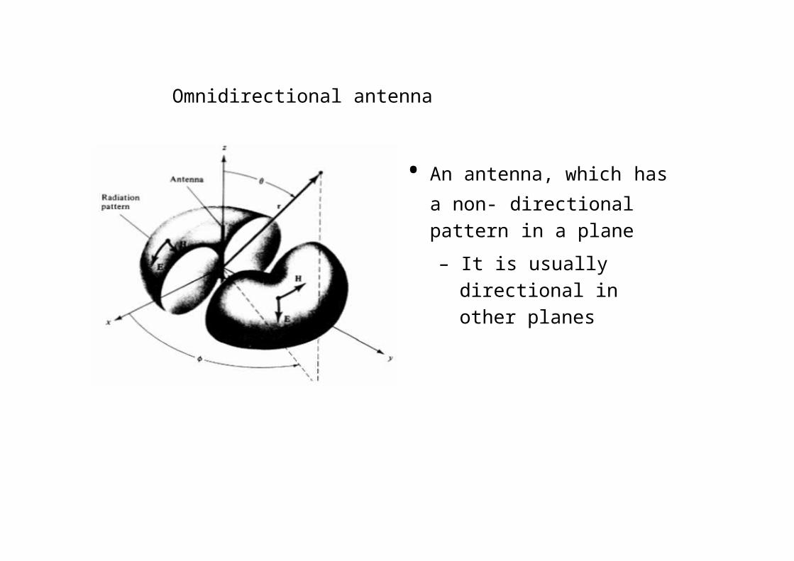
Omnidirectional antenna
• An antenna, which has a non- directional pattern in a plane
– It is usually directional in other planes
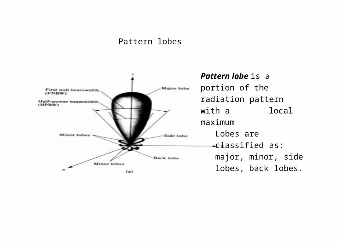
Pattern lobes
Pattern lobe is a portion of the radiation pattern with a local maximum
Lobes are classified as: major, minor, side lobes, back lobes.
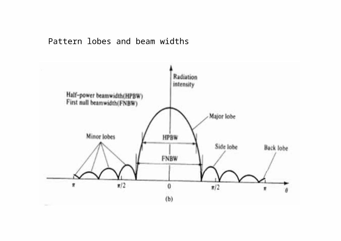
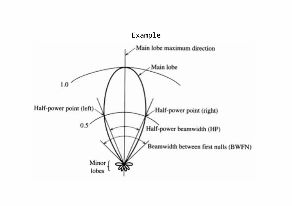
Pattern lobes and beam widths
Example
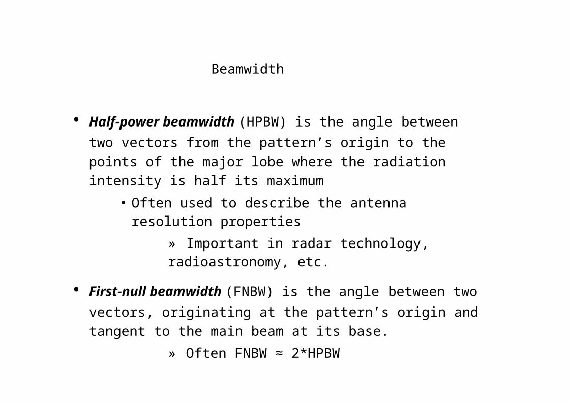
Beamwidth
• Half-power beamwidth (HPBW) is the angle between two vectors from the pattern’s origin to the points of the major lobe where the radiation intensity is half its maximum
• Often used to describe the antenna resolution properties
» Important in radar technology, radioastronomy, etc.
• First-null beamwidth (FNBW) is the angle between two vectors, originating at the pattern’s origin and tangent to the main beam at its base.
» Often FNBW ≈ 2*HPBW
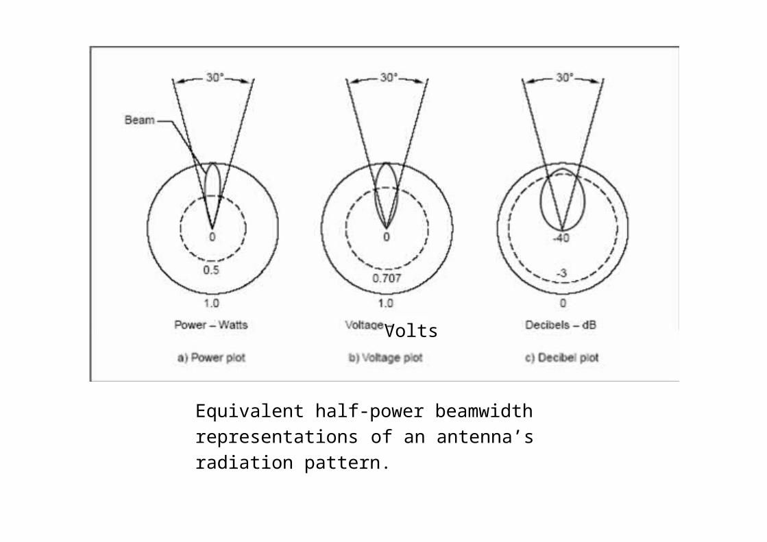
Volts
Equivalent half-power beamwidth representations of an antenna’s radiation pattern.
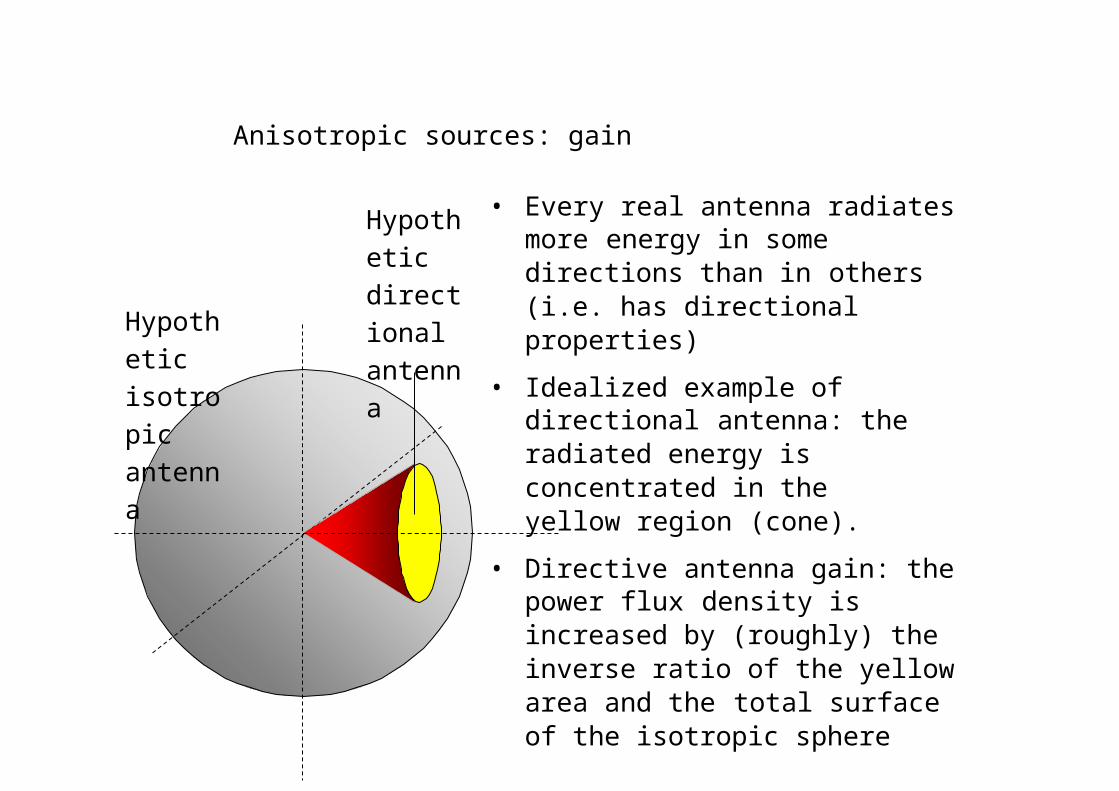
Anisotropic sources: gain
Hypothetic isotropic antenna
Hypothetic directional antenna
• Every real antenna radiates more energy in some directions than in others (i.e. has directional properties)
• Idealized example of directional antenna: the radiated energy is concentrated in the yellow region (cone).
• Directive antenna gain: the power flux density is increased by (roughly) the inverse ratio of the yellow area and the total surface of the isotropic sphere
– Gain in the field intensity may also be considered - it is equal to the square root of the power gain.
ω
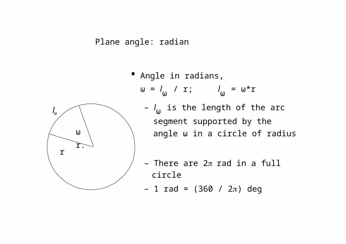
Plane angle: radian
• Angle in radians,ω = lω / r; lω = ω*r
l – lω is the length of the arc segment
supported by theω angle ω in a circle of radius r.
r– There are 2rad in a full
circle
– 1 rad = (360 / 2) deg
•
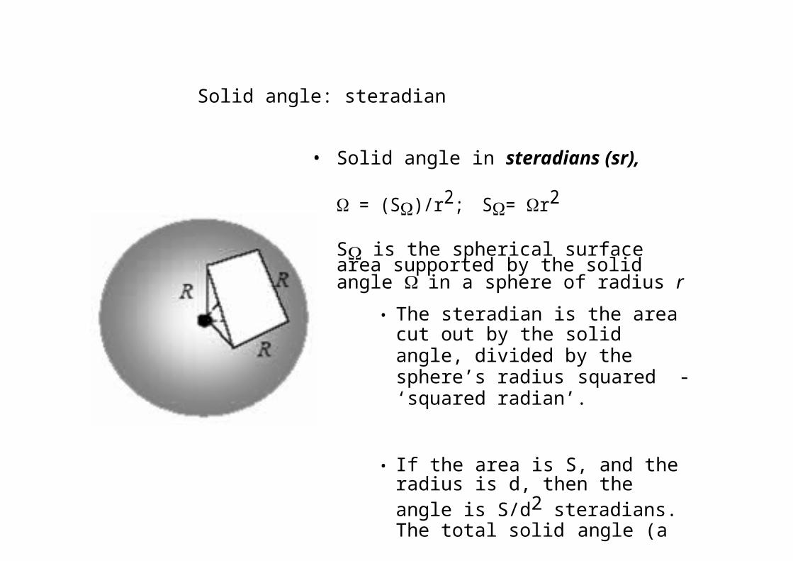
Solid angle: steradian
• Solid angle in steradians (sr),
= (S)/r2; S= r2
S is the spherical surface area supported by the solid angle in a sphere of radius r
• The steradian is the area cut out by the solid angle, divided by the sphere’s radius squared - ‘squared radian’.
• If the area is S, and the radius is d, then the angle is S/d2 steradians. The total solid angle (a full sphere) is thus 4steradians.
As one radian is 180/π = 57.3 degrees, the total solid angle is 4x (57.3)2 41253 square degrees, one steradian is 3282.806 square degrees, and one square degree is about 305 x 10-6 steradians
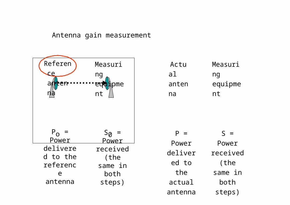
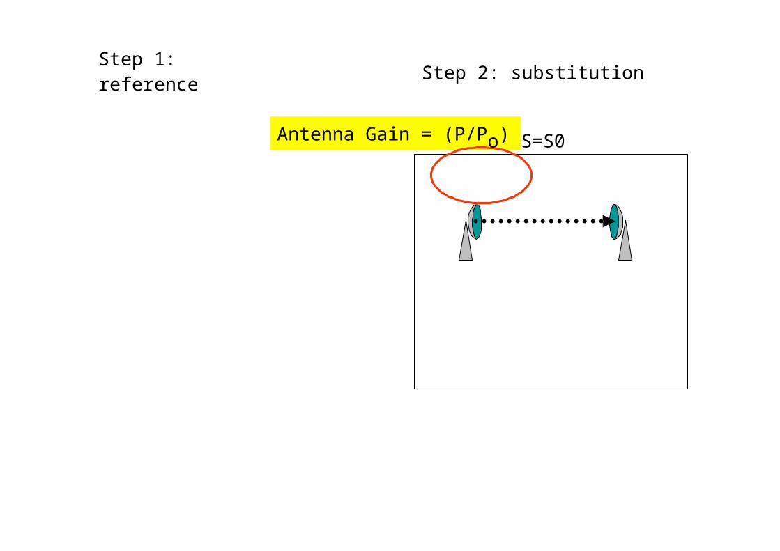
Antenna gain measurement
Reference antenna
Measuring equipment
Actual antenna
Measuring equipment
Po = Power delivered to
the reference antenna
S0 = Power received (the same in both steps)
P = Power delivered to the actual antenna
S = Power received
(the same in both steps)
Step 1: reference Step 2: substitution
Antenna Gain = (P/Po) S=S0
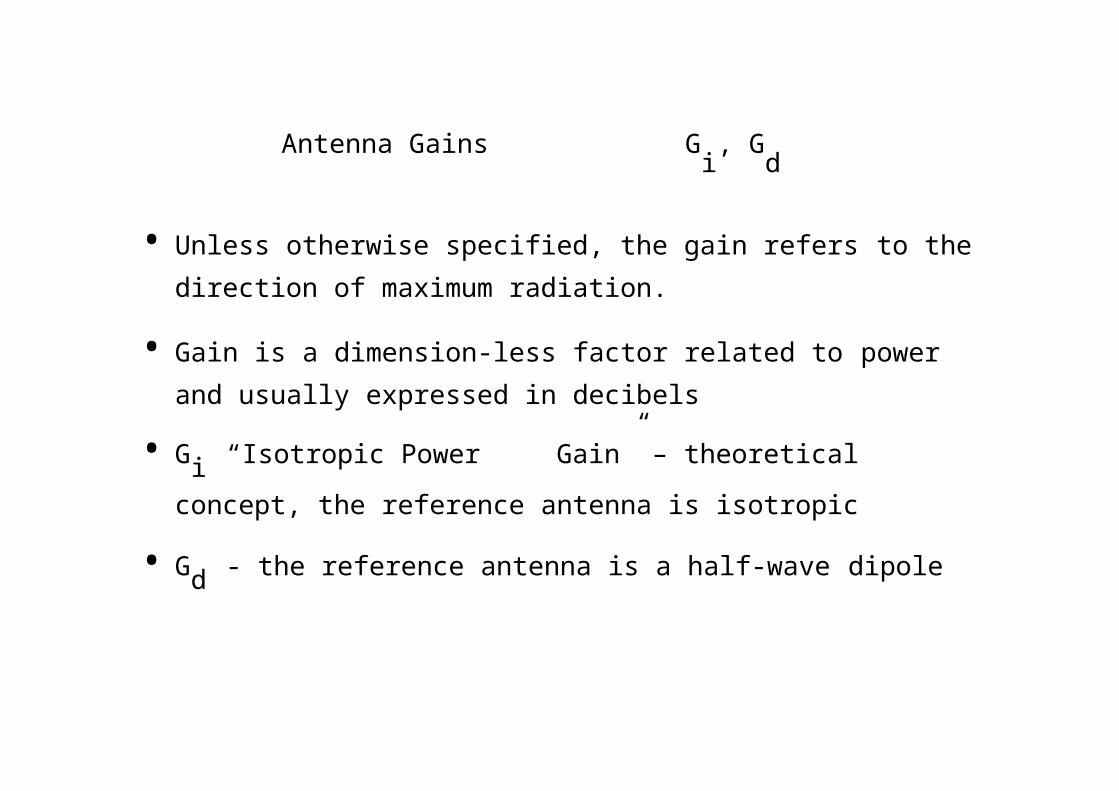
Antenna Gains Gi, G
d
• Unless otherwise specified, the gain refers to the direction of maximum radiation.
• Gain is a dimension-less factor related to power and usually expressed in decibels
• Gi “Isotropic Power Gain” – theoretical concept, the
reference antenna is isotropic
• Gd - the reference antenna is a half-wave dipole
Typical Gain and Beamwidth
Type of antenna Gi [dB] BeamW.
Isotropic 0 3600x3600
Half-wave Dipole 2 3600x1200
Helix (10 turn) 14 350x350
Small dish 16 300x300
Large dish 45 10x10
Gain, Directivity, Radiation Efficiency
• The radiation intensity, directivityG( ,) D( ,)
and gain are measures of the ability of an antenna to concentrate power in a particular direction.
• Directivity relates to the power radiated by antenna (P0 )
• Gain relates to the power delivered to antenna (PT)
PT
P0
• : radiation efficiency (0.5 - 0.75)
Antenna gain and effective area
• Effective area: Measure of the effective absorption area presented by an antenna to an incident plane wave.
• Depends on the antenna gain and wavelength2
Ae
4G(, ) [m
2 ]
Aperture efficiency: a = Ae / AA: physical area of antenna’s aperture, square meters
e.i.r.p.
• Equivalent Isotropically Radiated Power (in a given direction):
e.i.r. p. PGi
• The product of the power supplied to the antenna and the antenna gain (relative to an isotropic antenna) in a given direction
Linear Polarization
In a linearly polarized
plane wave the direction of the E (or
H) vector is constant .
Polarization ellipse
Ex• The superposition of two
coherent plane-wave
M components results in an
Ey elliptically polarized wave
•
N The polarization ellipse is• defined by its axial ratio
N/M (ellipticity), tilt angle
and sense of rotation
Elliptical Polarization
LHC
Ex = cos (wt) Ey = cos (wt)
Ex = cos (wt)Ey = cos (wt+pi/4)
Ex = cos (wt) Ey = -sin (wt)
Ex = cos (wt)Ey = cos (wt+3pi/4)
Ex = cos (wt)Ey = -cos (wt+pi/4)
RHCEx = cos (wt) Ey = sin (wt)
:
• At any moment in a chosen reference point in space, there is actually a single electric vector E (and associated magnetic vector H).
• This is the result of superposition (addition) of the instantaneous fields E (and H) produced by all radiation sources active at the moment.
• The separation of fields by their wavelength, polarization, or direction is the result of ‘filtration’.
Polarization Efficiency
• The power received by an antennafrom a particular direction is maximal if the polarization of the incident wave and the polarization of the antenna in the wave arrival direction have:
– the same axial ratio
– the same sense of polarization
– the same spatial orientation
.
2
Polarization filters/ reflectors
Wall of thin parallel wires (conductors)
|E1|>0 |E | = 0
|E1|
>0|E2| ~ |E2|
Vector E wires
Vector E wires
Reflecting
Wire distance ~ 0.1
Transparent
• At the surface of ideal conductor the tangential electrical field component = 0
Gen
erat
or
Transmitting antenna equivalent circuit
Transmitter Transm. line Radio wave
jXG
RG
VG
jXA
Rr
Rl
The transmitter with the transmission line is represented by an (Thevenin) equivalent
generatorThe antenna is represented by its input impedance
(which is frequency-dependent and is
influenced by objects nearby) as seem from the generator
jXA represents energy stored in electric (Ee) and magnetic (Em) near-field components; if |Ee| = |Em| then XA = 0 (antenna resonance)
Rr represents energy radiated into space (far-field components)Rl represents energy lost, i.e. transformed
2
Power vs. field strength
Pr E E
Z0
Pr Z0
E E2 E
2
EH
Z0Z0 377 ohms
for plane wave in free
space
Ant
enna
Receiving antenna equivalent circuit
Radio wave
Antenna
Transm.line
Receiver
jXA
Rr
Rl
VA
jXL
RL
The antenna with the transmission line is represented by an (Thevenin) equivalent generator
The receiver is represented by its input impedance as seen from the antenna terminals (i.e. transformed by the transmission line)
VA is the (induced by the incident wave) voltage at the antenna terminals determined when the antenna is open circuited
PA
/ P
Am
ax
Power transfer
1
0.5
0 0.1 110
RA / RG; (XA+XG = 0)
• The maximum power is delivered to (or from) the antenna when the antenna impedance and the impedance of the equivalent generator (or load) are matched
• When the impedances are matched
– Half of the source power is delivered to the load and half is dissipated within the (equivalent) generator as heat
– In the case of receiving antenna, a part (Pl) of the power captured is lost as heat in the antenna elements, the other part being reradiated (scattered) back into space
• Even when the antenna losses tend to zero, still only half of the power captured is delivered to the load (in the case of conjugate matching), the other half being scattered back into space
Satellite antennas (TV)
• Not an array!
Owens Valley Radio
Observatory Array
The Earth’s atmosphere is transparent in the narrow visible-light window(4000-7000angstroms) and the radio band between 1 mmand 10 m.

New Mexico Very Large Array
27 antennas along 3 railroad tracks provide baselines up to 35 km. Radio images are formed by correlating the signals garnered by each antenna.
R Struzak
2 GHz adaptive antenna array
• A set of 48 2 GHz antennas
• Switched beam antennas
– Based on switching function between separate directive antennas or predefined beams of an array
• Space Division Multiple Access (SDMA) = allocating an angle direction sector to each user– In a TDMA system, two users will be
allocated to the same time slot and the same carrier frequency
– They will be differentiated by different direction angles
Adaptive (“Intelligent”) Antennas
• Array of N antennas in a linear, circular, or planar configuration
• Used for selection signals from desired sources and suppress incident signals from undesired sources
• The antenna pattern track the sources
• It is then adjusted to null out the interferers and to maximize the signal to interference ratio (SIR)
• Able to receive and combine constructively multipath signals
Relative distance, Br
Z /
377
Field impedance
100
10
1
0.1
0.01
Short dipole
Small loop
Field impedanc e
Z = E/Hdepends
on the antennatype and
0.01 0.1 1 10100
Distance / (lambda/ 2Pi)
on distance
Far-Field, Near-Field
• Near-field region:
– Angular distribution of energy depends on distance from the antenna;
– Reactive field components dominate (L, C)
• Far-field region:
– Angular distribution of energy is independent on distance;
– Radiating field component dominates (R)
– The resultant EM field can locally be treated as uniform (TEM)
• The EM field at large distances from an antenna can be treated as originated at a point source - fictitious volume-less emitter.
• The EM field in a homogenous unlimited medium at large distances from an antenna can be approximated by an uniform plane TEM wave


