1
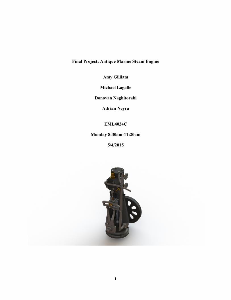
Final Project: Antique Marine Steam Engine
Amy Gilliam
Michael Lagalle
Donovan Naghitorabi
Adrian Neyra
EML4024C
Monday 8:30am-11:20am
5/4/2015
2
Table of Contents
I. Introduction 3
II. Mechanical Design: Parts 4
1. Case Sub-Assembly Parts 4 2. Powertrain Sub-Assembly Parts 6 3. Cylinder Sub-Assembly Parts 12 4. Valve Sub-Assembly Parts 19 5. Piston Sub-Assembly Parts 22 6. Link Sub-Assembly Parts 24 7. Handle Sub-Assembly Parts 27
III. Mechanical Design: Assembly 29
1. Case Sub-Assembly 29 2. Powertrain Sub-Assembly 33 3. Cylinder Sub-Assembly 36 4. Valve Sub-Assembly 39 5. Piston Sub-Assembly 43 6. Link Sub-Assembly 44 7. Handle Sub-Assembly 49 8. Final Assembly 53
IV. Mechanism Model Mechanics 57
V. Mechanism Kinematics 57
VI. Structural Analysis 58
VII. Conclusion 60
VIII. References 60
3
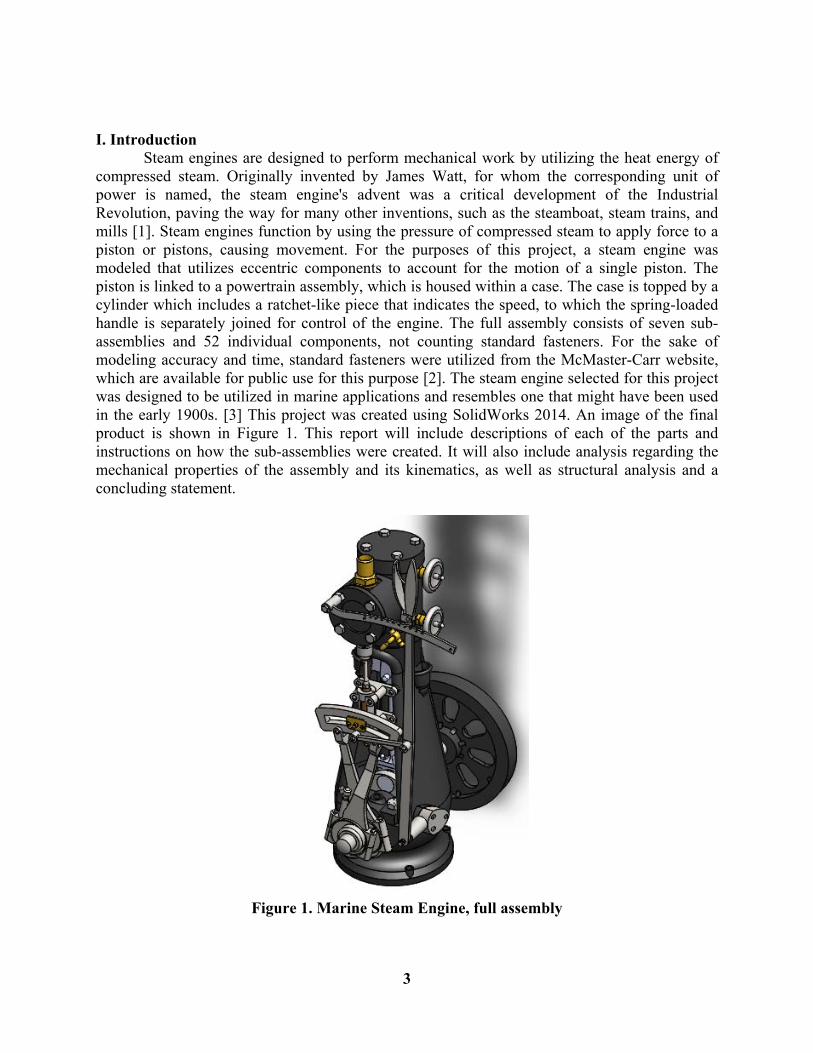
I. Introduction Steam engines are designed to perform mechanical work by utilizing the heat energy of compressed steam. Originally invented by James Watt, for whom the corresponding unit of power is named, the steam engine's advent was a critical development of the Industrial Revolution, paving the way for many other inventions, such as the steamboat, steam trains, and mills [1]. Steam engines function by using the pressure of compressed steam to apply force to a piston or pistons, causing movement. For the purposes of this project, a steam engine was modeled that utilizes eccentric components to account for the motion of a single piston. The piston is linked to a powertrain assembly, which is housed within a case. The case is topped by a cylinder which includes a ratchet-like piece that indicates the speed, to which the spring-loaded handle is separately joined for control of the engine. The full assembly consists of seven sub-assemblies and 52 individual components, not counting standard fasteners. For the sake of modeling accuracy and time, standard fasteners were utilized from the McMaster-Carr website, which are available for public use for this purpose [2]. The steam engine selected for this project was designed to be utilized in marine applications and resembles one that might have been used in the early 1900s. [3] This project was created using SolidWorks 2014. An image of the final product is shown in Figure 1. This report will include descriptions of each of the parts and instructions on how the sub-assemblies were created. It will also include analysis regarding the mechanical properties of the assembly and its kinematics, as well as structural analysis and a concluding statement.
Figure 1. Marine Steam Engine, full assembly
4
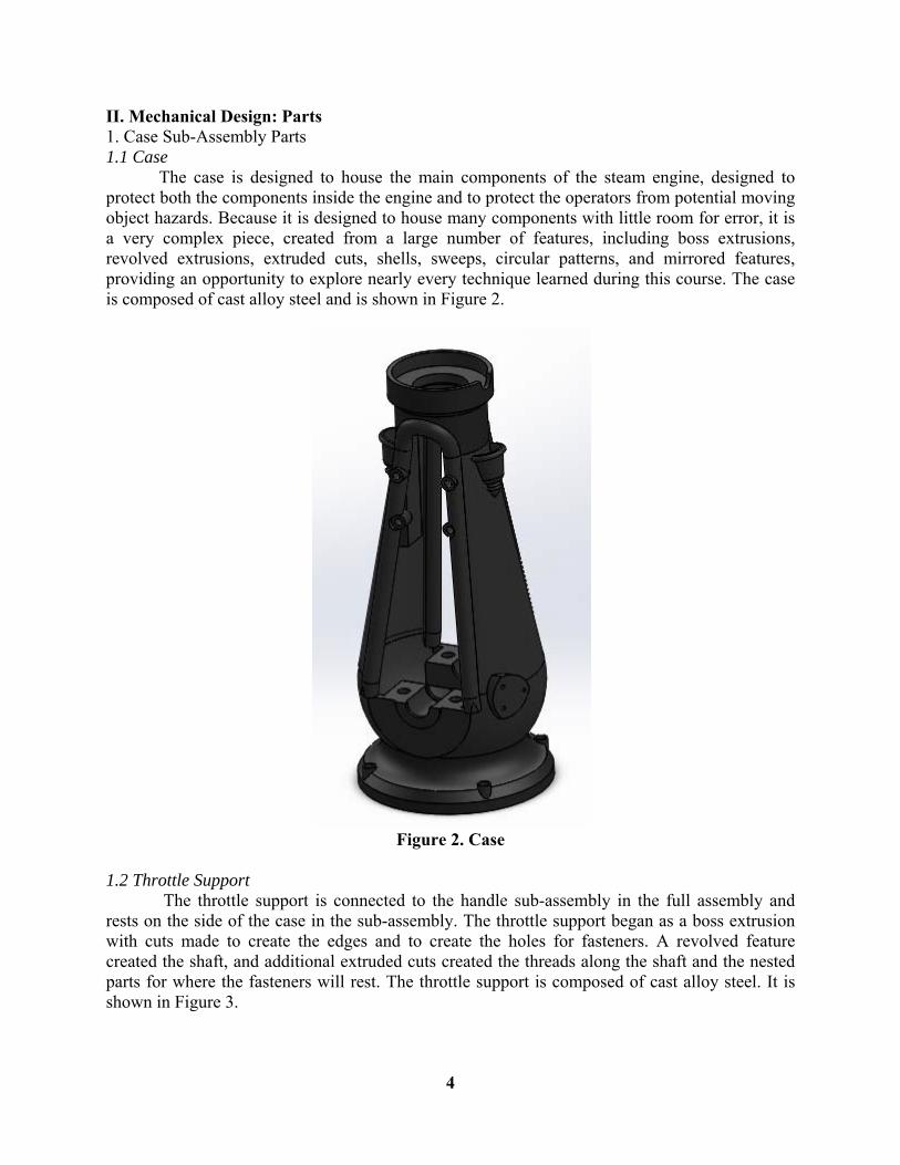
II. Mechanical Design: Parts 1. Case Sub-Assembly Parts 1.1 Case The case is designed to house the main components of the steam engine, designed to protect both the components inside the engine and to protect the operators from potential moving object hazards. Because it is designed to house many components with little room for error, it is a very complex piece, created from a large number of features, including boss extrusions, revolved extrusions, extruded cuts, shells, sweeps, circular patterns, and mirrored features, providing an opportunity to explore nearly every technique learned during this course. The case is composed of cast alloy steel and is shown in Figure 2.
Figure 2. Case
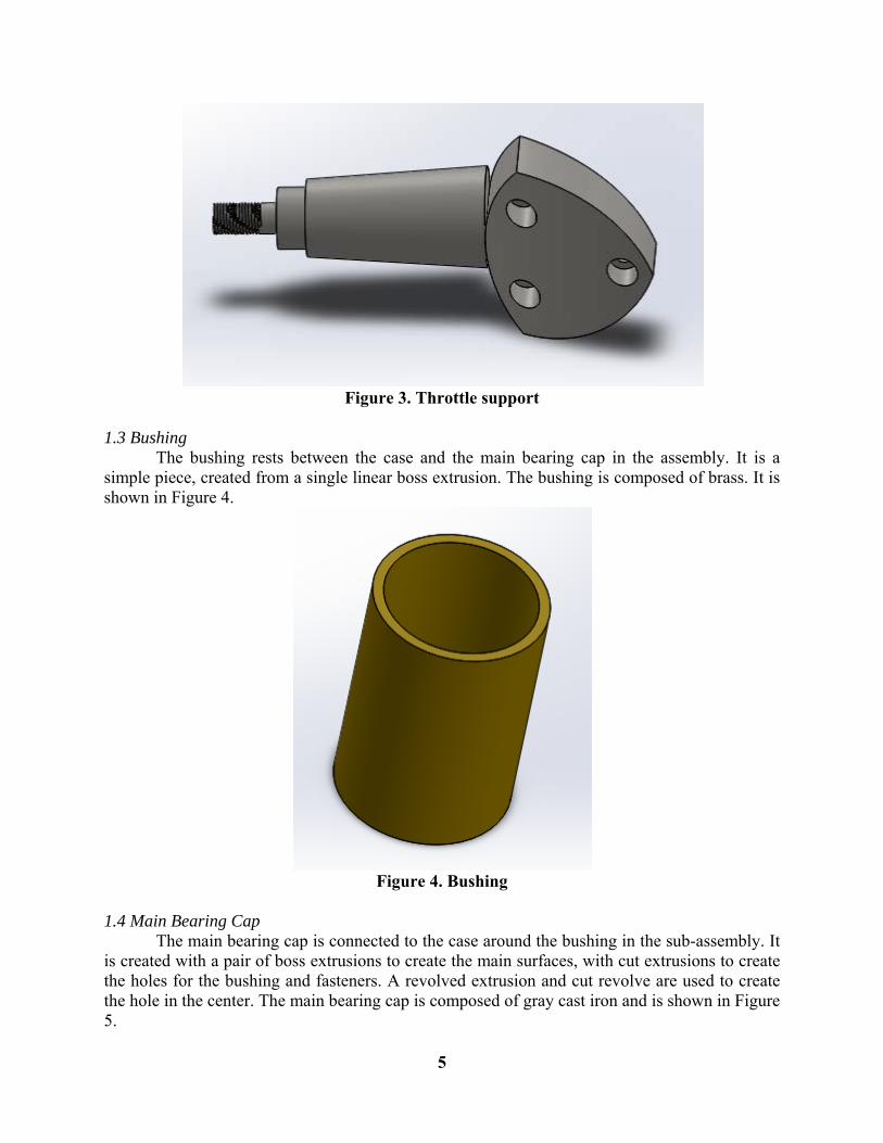
1.2 Throttle Support The throttle support is connected to the handle sub-assembly in the full assembly and rests on the side of the case in the sub-assembly. The throttle support began as a boss extrusion with cuts made to create the edges and to create the holes for fasteners. A revolved feature created the shaft, and additional extruded cuts created the threads along the shaft and the nested parts for where the fasteners will rest. The throttle support is composed of cast alloy steel. It is shown in Figure 3.
5
Figure 3. Throttle support
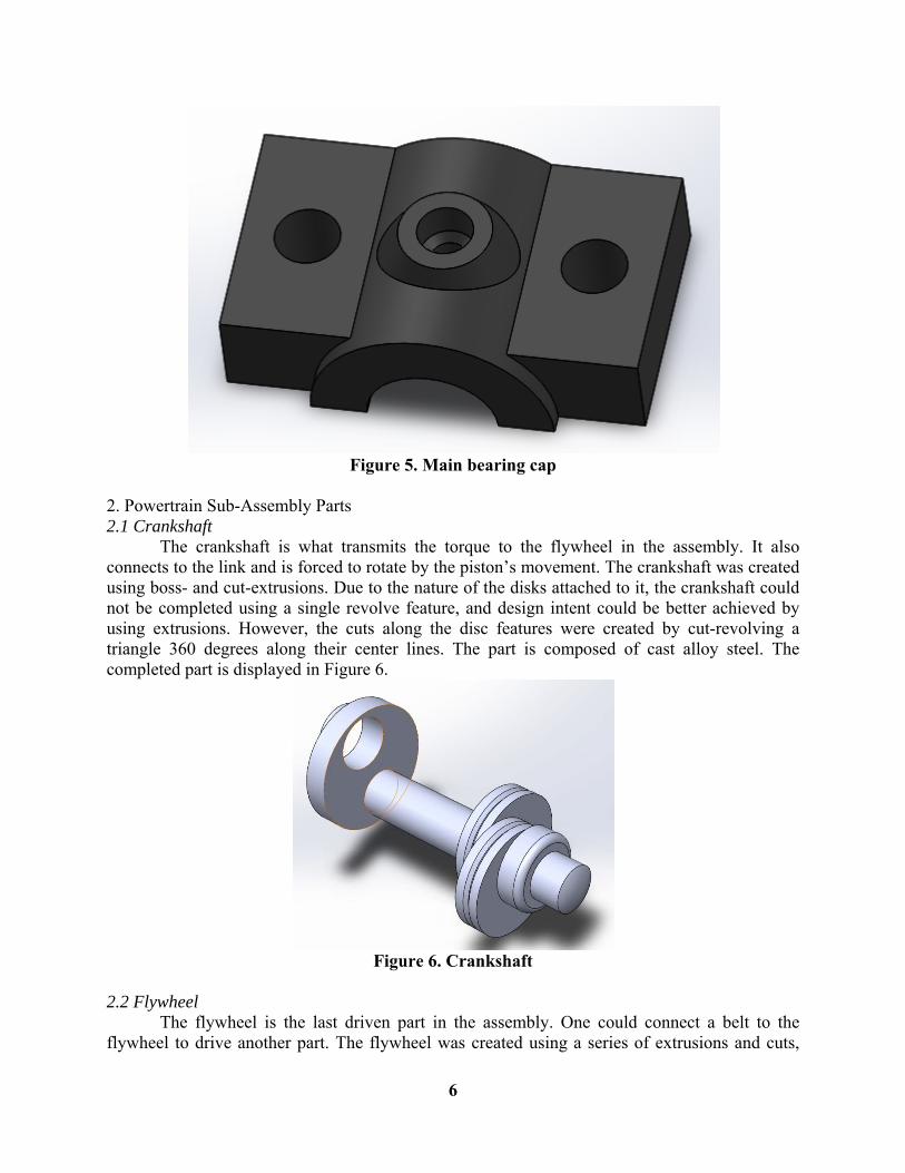
1.3 Bushing The bushing rests between the case and the main bearing cap in the assembly. It is a simple piece, created from a single linear boss extrusion. The bushing is composed of brass. It is shown in Figure 4.
Figure 4. Bushing
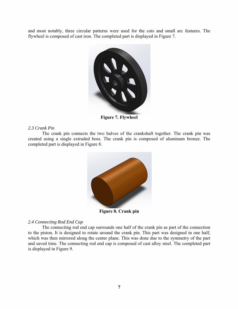
1.4 Main Bearing Cap The main bearing cap is connected to the case around the bushing in the sub-assembly. It is created with a pair of boss extrusions to create the main surfaces, with cut extrusions to create the holes for the bushing and fasteners. A revolved extrusion and cut revolve are used to create the hole in the center. The main bearing cap is composed of gray cast iron and is shown in Figure 5.
6
Figure 5. Main bearing cap
2. Powertrain Sub-Assembly Parts 2.1 Crankshaft
The crankshaft is what transmits the torque to the flywheel in the assembly. It also connects to the link and is forced to rotate by the piston’s movement. The crankshaft was created using boss- and cut-extrusions. Due to the nature of the disks attached to it, the crankshaft could not be completed using a single revolve feature, and design intent could be better achieved by using extrusions. However, the cuts along the disc features were created by cut-revolving a triangle 360 degrees along their center lines. The part is composed of cast alloy steel. The completed part is displayed in Figure 6.
Figure 6. Crankshaft
2.2 Flywheel The flywheel is the last driven part in the assembly. One could connect a belt to the flywheel to drive another part. The flywheel was created using a series of extrusions and cuts,
7
and most notably, three circular patterns were used for the cuts and small arc features. The flywheel is composed of cast iron. The completed part is displayed in Figure 7.
Figure 7. Flywheel
2.3 Crank Pin
The crank pin connects the two halves of the crankshaft together. The crank pin was created using a single extruded boss. The crank pin is composed of aluminum bronze. The completed part is displayed in Figure 8.
Figure 8. Crank pin
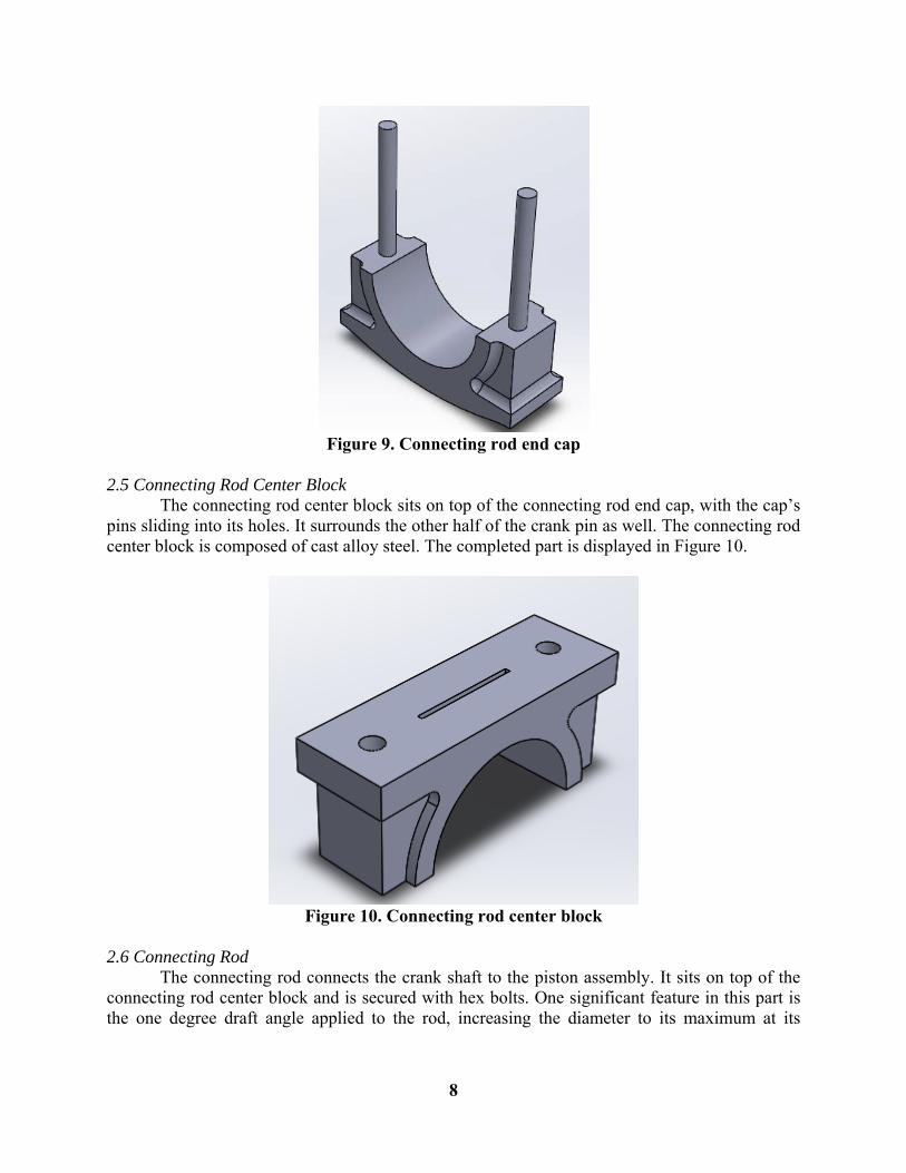
2.4 Connecting Rod End Cap The connecting rod end cap surrounds one half of the crank pin as part of the connection to the piston. It is designed to rotate around the crank pin. This part was designed in one half, which was then mirrored along the center plane. This was done due to the symmetry of the part and saved time. The connecting rod end cap is composed of cast alloy steel. The completed part is displayed in Figure 9.
8
Figure 9. Connecting rod end cap
2.5 Connecting Rod Center Block
The connecting rod center block sits on top of the connecting rod end cap, with the cap’s pins sliding into its holes. It surrounds the other half of the crank pin as well. The connecting rod center block is composed of cast alloy steel. The completed part is displayed in Figure 10.
Figure 10. Connecting rod center block
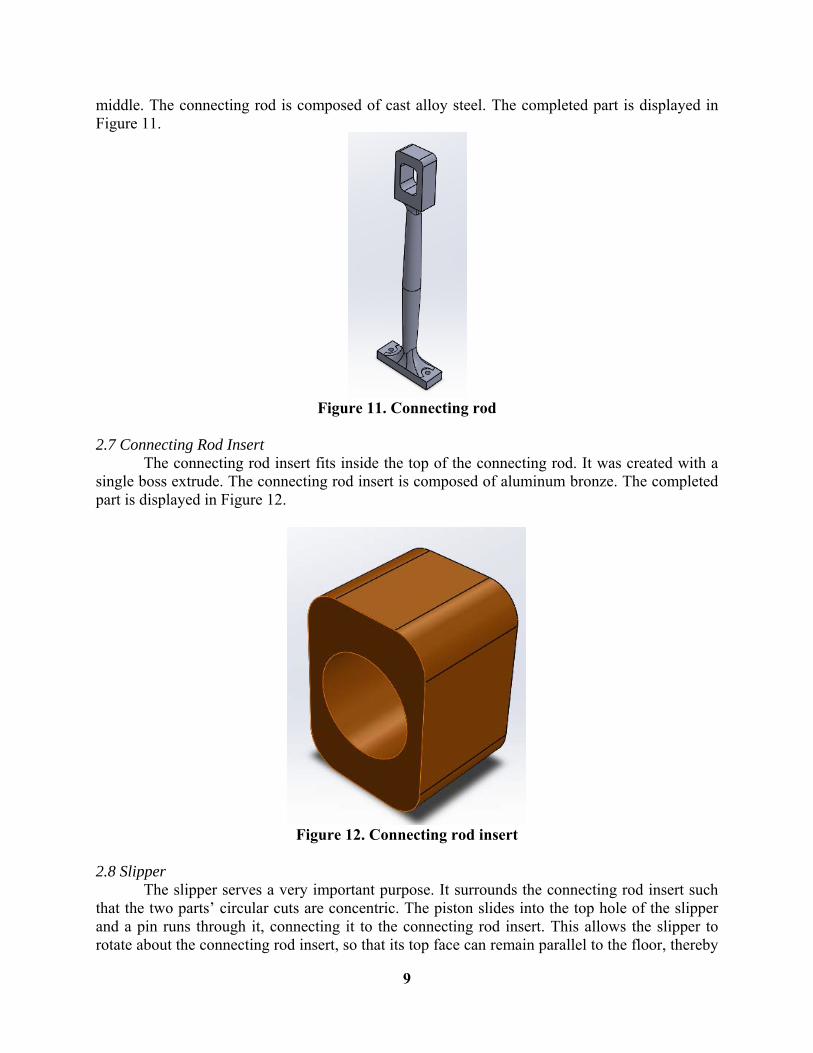
2.6 Connecting Rod The connecting rod connects the crank shaft to the piston assembly. It sits on top of the connecting rod center block and is secured with hex bolts. One significant feature in this part is the one degree draft angle applied to the rod, increasing the diameter to its maximum at its
9
middle. The connecting rod is composed of cast alloy steel. The completed part is displayed in Figure 11.
Figure 11. Connecting rod
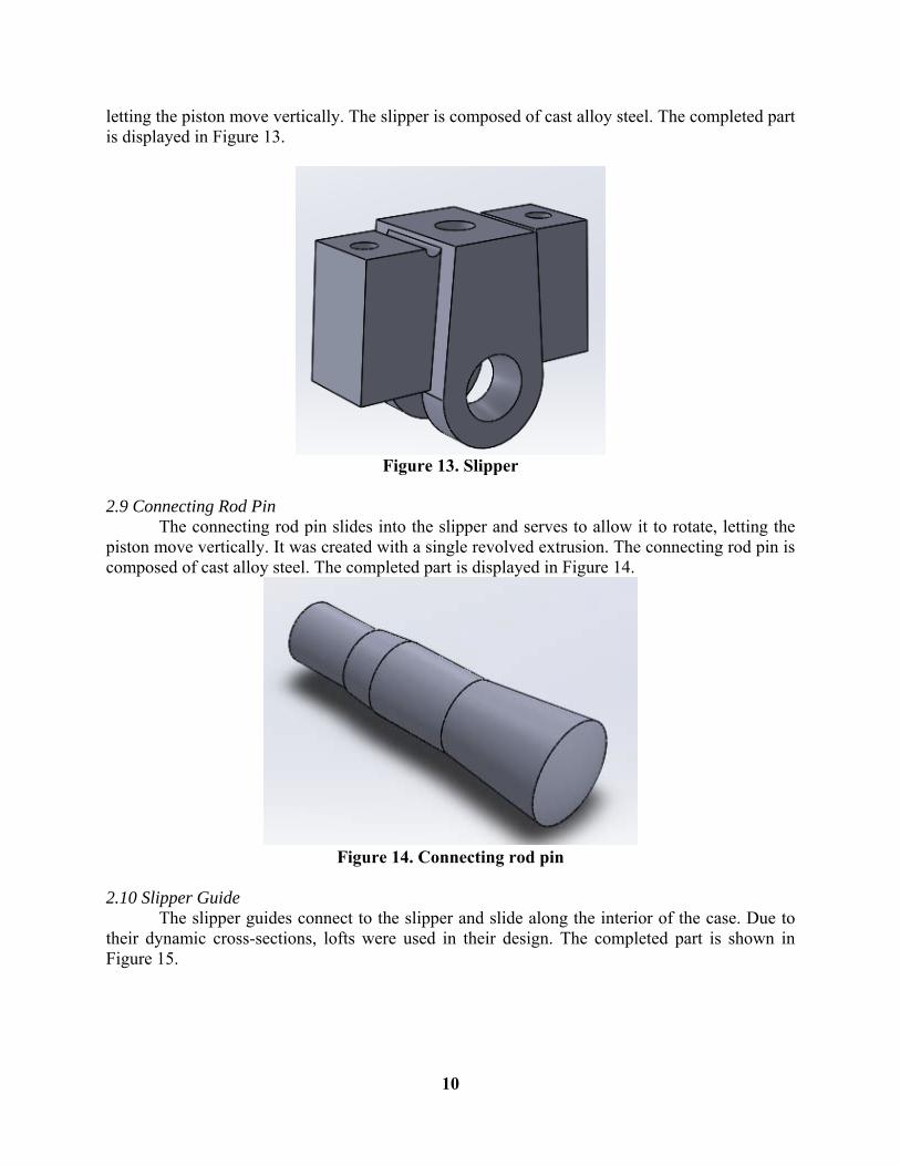
2.7 Connecting Rod Insert The connecting rod insert fits inside the top of the connecting rod. It was created with a single boss extrude. The connecting rod insert is composed of aluminum bronze. The completed part is displayed in Figure 12.
Figure 12. Connecting rod insert
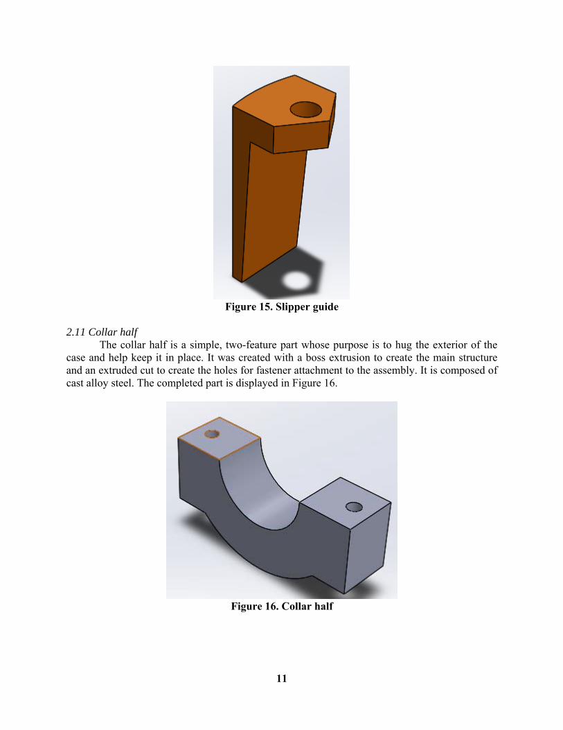
2.8 Slipper
The slipper serves a very important purpose. It surrounds the connecting rod insert such that the two parts’ circular cuts are concentric. The piston slides into the top hole of the slipper and a pin runs through it, connecting it to the connecting rod insert. This allows the slipper to rotate about the connecting rod insert, so that its top face can remain parallel to the floor, thereby
10
letting the piston move vertically. The slipper is composed of cast alloy steel. The completed part is displayed in Figure 13.
Figure 13. Slipper
2.9 Connecting Rod Pin
The connecting rod pin slides into the slipper and serves to allow it to rotate, letting the piston move vertically. It was created with a single revolved extrusion. The connecting rod pin is composed of cast alloy steel. The completed part is displayed in Figure 14.
Figure 14. Connecting rod pin
2.10 Slipper Guide The slipper guides connect to the slipper and slide along the interior of the case. Due to their dynamic cross-sections, lofts were used in their design. The completed part is shown in Figure 15.
11
Figure 15. Slipper guide
2.11 Collar half The collar half is a simple, two-feature part whose purpose is to hug the exterior of the case and help keep it in place. It was created with a boss extrusion to create the main structure and an extruded cut to create the holes for fastener attachment to the assembly. It is composed of cast alloy steel. The completed part is displayed in Figure 16.
Figure 16. Collar half
12
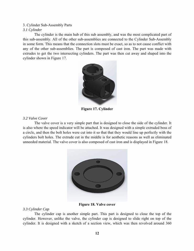
3. Cylinder Sub-Assembly Parts 3.1 Cylinder The cylinder is the main hub of this sub assembly, and was the most complicated part of this sub-assembly. All of the other sub-assemblies are connected to the Cylinder Sub-Assembly in some form. This means that the connection slots must be exact, so as to not cause conflict with any of the other sub-assemblies. The part is composed of cast iron. The part was made with extrudes to get the two intersecting cylinders. The part was then cut away and shaped into the cylinder shown in Figure 17.
Figure 17. Cylinder
3.2 Valve Cover The valve cover is a very simple part that is designed to close the side of the cylinder. It is also where the speed indicator will be attached. It was designed with a simple extruded boss of a circle, and then the bolt holes were cut into it so that that they would line up perfectly with the cylinders bolt holes. The extrude cut in the middle is for aesthetic reasons as well as eliminated unneeded material. The valve cover is also composed of cast iron and is displayed in Figure 18.
Figure 18. Valve cover
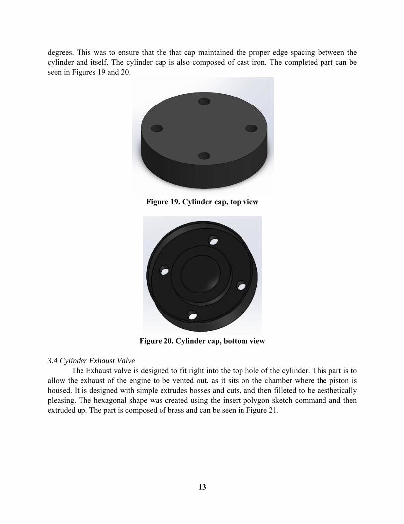
3.3 Cylinder Cap The cylinder cap is another simple part. This part is designed to close the top of the cylinder. However, unlike the valve, the cylinder cap is designed to slide right on top of the cylinder. It is designed with a sketch of a section view, which was then revolved around 360
13
degrees. This was to ensure that the that cap maintained the proper edge spacing between the cylinder and itself. The cylinder cap is also composed of cast iron. The completed part can be seen in Figures 19 and 20.
Figure 19. Cylinder cap, top view
Figure 20. Cylinder cap, bottom view
3.4 Cylinder Exhaust Valve The Exhaust valve is designed to fit right into the top hole of the cylinder. This part is to allow the exhaust of the engine to be vented out, as it sits on the chamber where the piston is housed. It is designed with simple extrudes bosses and cuts, and then filleted to be aesthetically pleasing. The hexagonal shape was created using the insert polygon sketch command and then extruded up. The part is composed of brass and can be seen in Figure 21.

14
Figure 21. Cylinder exhaust valve
3.5 Bottom of Cylinder Packing Gland The bottom of the packing gland is a simple part composed of cast alloy steel. It is designed to close the gland and seal the cylinder holding a smaller rubber cylinder that serves as a seal. It was designed with two simple extruded bosses, and then three holes extrude cut down into the part. The beveling on the top face was done with a simple sketch that was revolved around the central axis. The completed part is displayed in Figure 22.
Figure 22. Bottom of cylinder packing gland
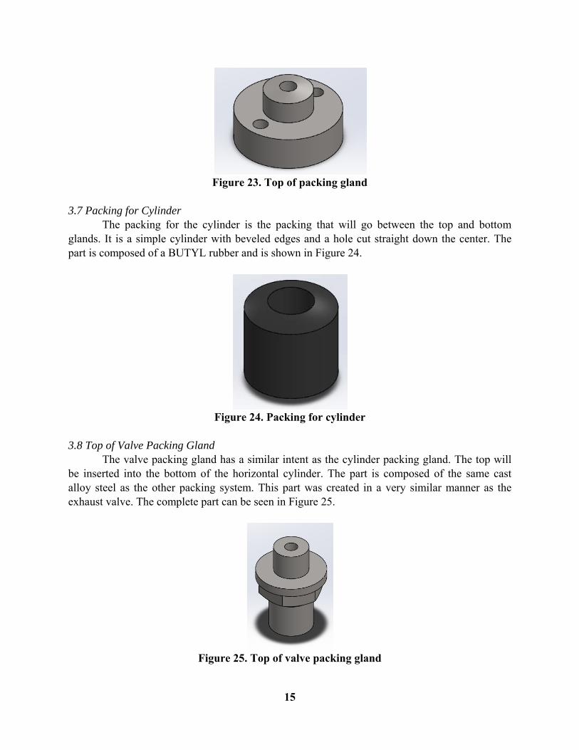
3.6 Top of Cylinder Packing Gland The top of the packing gland is also combined of cast alloy steel. It is designed to fit right into the bottom of the main cylinder. It has a hollowed center, where the cylindrical packaging will slide right into. It has two bolt holes that will align with bottom bolt holes of the cylinder as well as the bolt holes on the bottom of the packing gland. The holes were created using extruded cuts, and the detailed beveled work was done with revolved cuts. The final part can be seen in Figure 23.
15
Figure 23. Top of packing gland
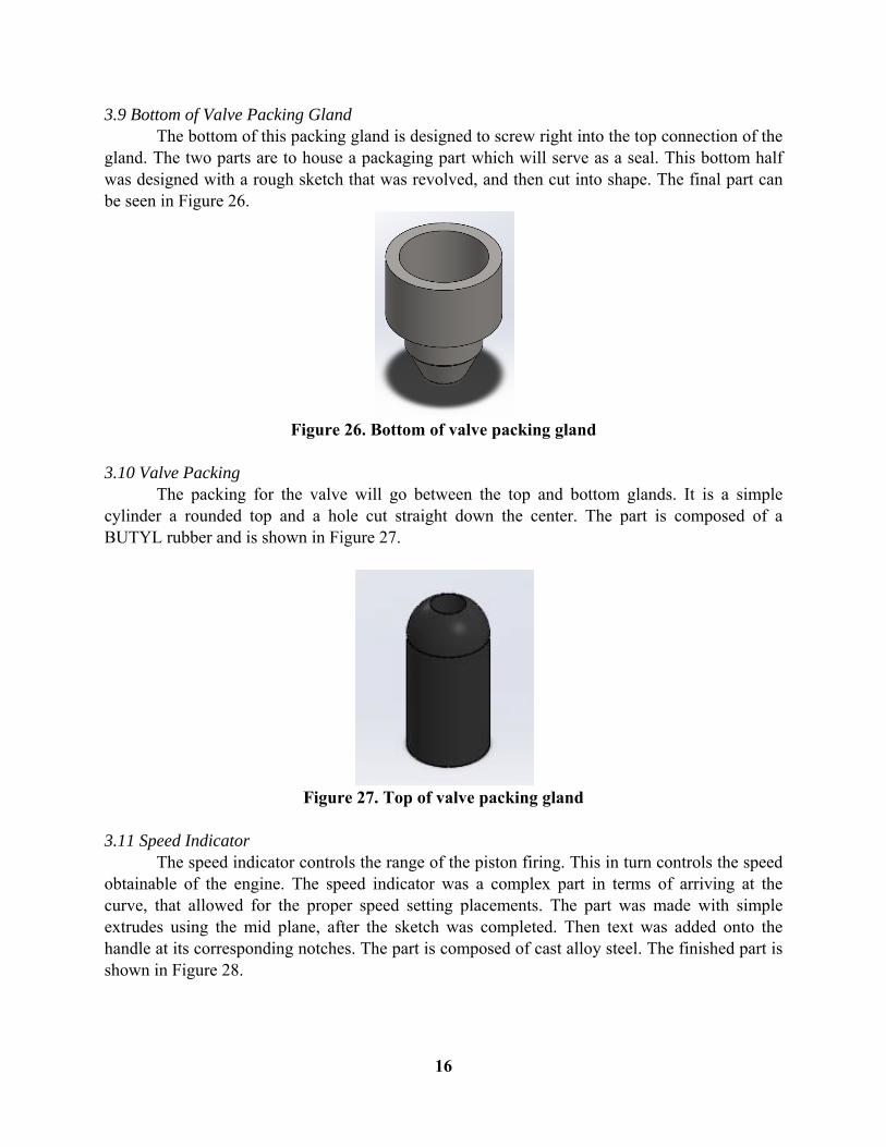
3.7 Packing for Cylinder The packing for the cylinder is the packing that will go between the top and bottom glands. It is a simple cylinder with beveled edges and a hole cut straight down the center. The part is composed of a BUTYL rubber and is shown in Figure 24.
Figure 24. Packing for cylinder
3.8 Top of Valve Packing Gland The valve packing gland has a similar intent as the cylinder packing gland. The top will be inserted into the bottom of the horizontal cylinder. The part is composed of the same cast alloy steel as the other packing system. This part was created in a very similar manner as the exhaust valve. The complete part can be seen in Figure 25.
Figure 25. Top of valve packing gland
16
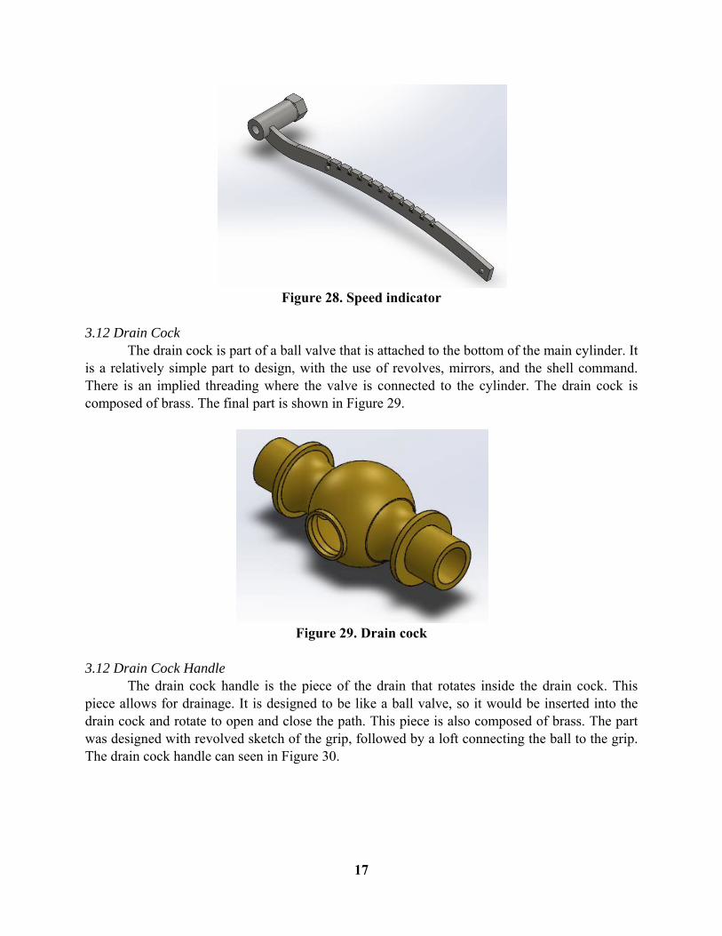
3.9 Bottom of Valve Packing Gland The bottom of this packing gland is designed to screw right into the top connection of the gland. The two parts are to house a packaging part which will serve as a seal. This bottom half was designed with a rough sketch that was revolved, and then cut into shape. The final part can be seen in Figure 26.
Figure 26. Bottom of valve packing gland
3.10 Valve Packing The packing for the valve will go between the top and bottom glands. It is a simple cylinder a rounded top and a hole cut straight down the center. The part is composed of a BUTYL rubber and is shown in Figure 27.
Figure 27. Top of valve packing gland
3.11 Speed Indicator The speed indicator controls the range of the piston firing. This in turn controls the speed obtainable of the engine. The speed indicator was a complex part in terms of arriving at the curve, that allowed for the proper speed setting placements. The part was made with simple extrudes using the mid plane, after the sketch was completed. Then text was added onto the handle at its corresponding notches. The part is composed of cast alloy steel. The finished part is shown in Figure 28.
17
Figure 28. Speed indicator
3.12 Drain Cock The drain cock is part of a ball valve that is attached to the bottom of the main cylinder. It is a relatively simple part to design, with the use of revolves, mirrors, and the shell command. There is an implied threading where the valve is connected to the cylinder. The drain cock is composed of brass. The final part is shown in Figure 29.
Figure 29. Drain cock
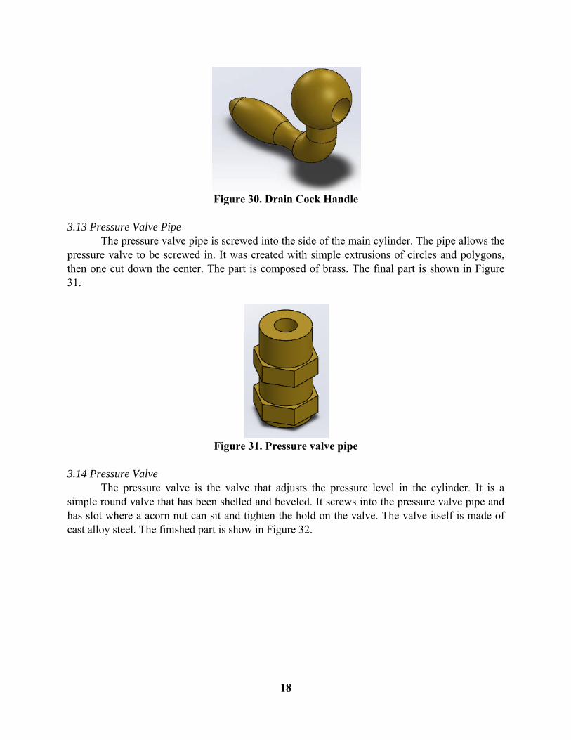
3.12 Drain Cock Handle The drain cock handle is the piece of the drain that rotates inside the drain cock. This piece allows for drainage. It is designed to be like a ball valve, so it would be inserted into the drain cock and rotate to open and close the path. This piece is also composed of brass. The part was designed with revolved sketch of the grip, followed by a loft connecting the ball to the grip. The drain cock handle can seen in Figure 30.
18
Figure 30. Drain Cock Handle
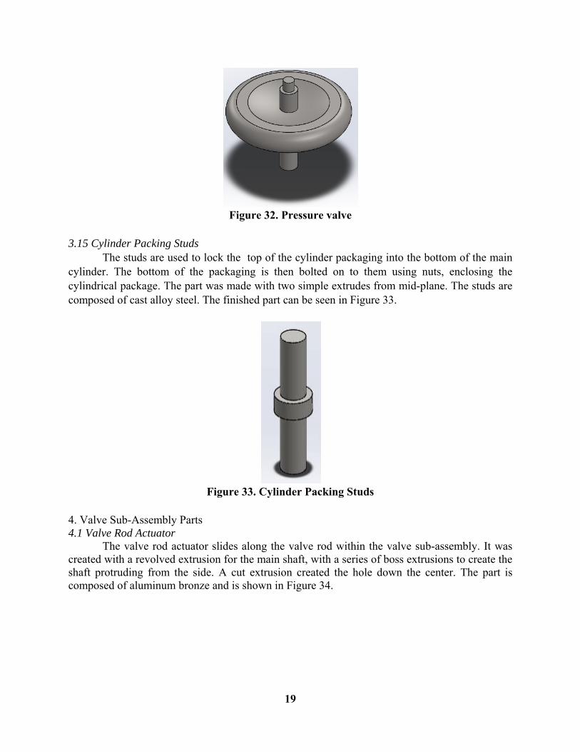
3.13 Pressure Valve Pipe The pressure valve pipe is screwed into the side of the main cylinder. The pipe allows the pressure valve to be screwed in. It was created with simple extrusions of circles and polygons, then one cut down the center. The part is composed of brass. The final part is shown in Figure 31.
Figure 31. Pressure valve pipe
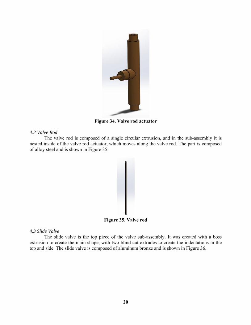
3.14 Pressure Valve The pressure valve is the valve that adjusts the pressure level in the cylinder. It is a simple round valve that has been shelled and beveled. It screws into the pressure valve pipe and has slot where a acorn nut can sit and tighten the hold on the valve. The valve itself is made of cast alloy steel. The finished part is show in Figure 32.
19
Figure 32. Pressure valve
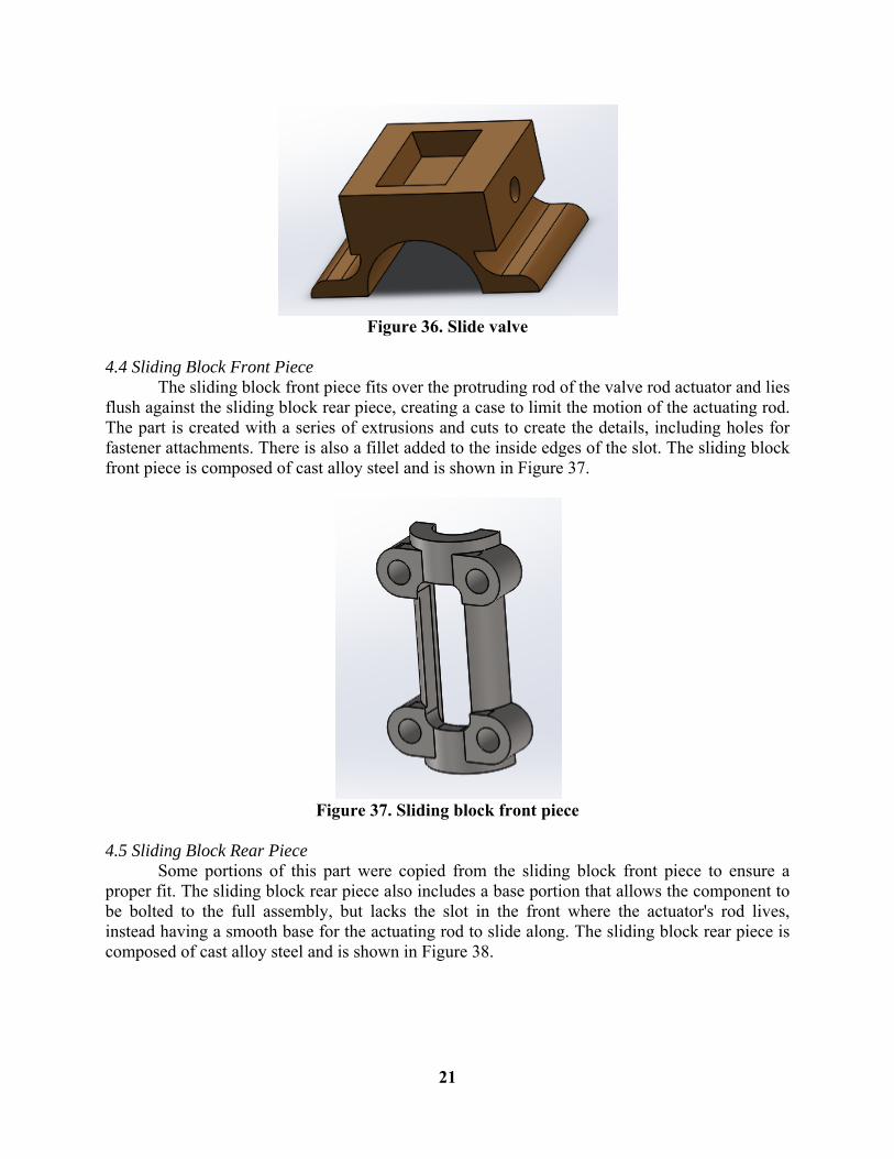
3.15 Cylinder Packing Studs The studs are used to lock the top of the cylinder packaging into the bottom of the main cylinder. The bottom of the packaging is then bolted on to them using nuts, enclosing the cylindrical package. The part was made with two simple extrudes from mid-plane. The studs are composed of cast alloy steel. The finished part can be seen in Figure 33.
Figure 33. Cylinder Packing Studs
4. Valve Sub-Assembly Parts 4.1 Valve Rod Actuator The valve rod actuator slides along the valve rod within the valve sub-assembly. It was created with a revolved extrusion for the main shaft, with a series of boss extrusions to create the shaft protruding from the side. A cut extrusion created the hole down the center. The part is composed of aluminum bronze and is shown in Figure 34.
20
Figure 34. Valve rod actuator
4.2 Valve Rod The valve rod is composed of a single circular extrusion, and in the sub-assembly it is nested inside of the valve rod actuator, which moves along the valve rod. The part is composed of alloy steel and is shown in Figure 35.
Figure 35. Valve rod
4.3 Slide Valve The slide valve is the top piece of the valve sub-assembly. It was created with a boss extrusion to create the main shape, with two blind cut extrudes to create the indentations in the top and side. The slide valve is composed of aluminum bronze and is shown in Figure 36.
21
Figure 36. Slide valve
4.4 Sliding Block Front Piece The sliding block front piece fits over the protruding rod of the valve rod actuator and lies flush against the sliding block rear piece, creating a case to limit the motion of the actuating rod. The part is created with a series of extrusions and cuts to create the details, including holes for fastener attachments. There is also a fillet added to the inside edges of the slot. The sliding block front piece is composed of cast alloy steel and is shown in Figure 37.
Figure 37. Sliding block front piece
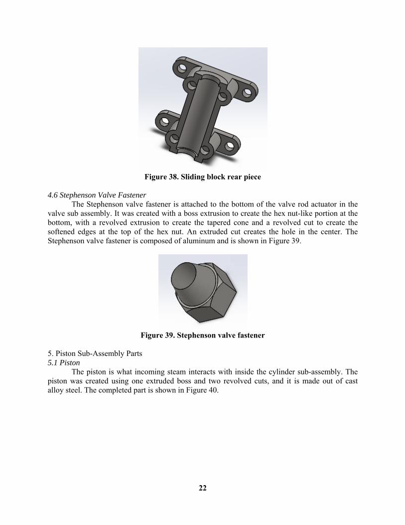
4.5 Sliding Block Rear Piece Some portions of this part were copied from the sliding block front piece to ensure a proper fit. The sliding block rear piece also includes a base portion that allows the component to be bolted to the full assembly, but lacks the slot in the front where the actuator's rod lives, instead having a smooth base for the actuating rod to slide along. The sliding block rear piece is composed of cast alloy steel and is shown in Figure 38.
22
Figure 38. Sliding block rear piece
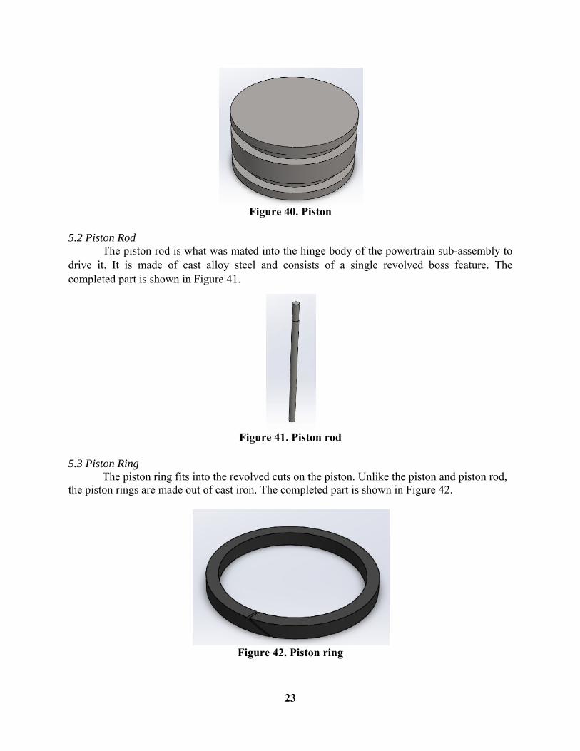
4.6 Stephenson Valve Fastener The Stephenson valve fastener is attached to the bottom of the valve rod actuator in the valve sub assembly. It was created with a boss extrusion to create the hex nut-like portion at the bottom, with a revolved extrusion to create the tapered cone and a revolved cut to create the softened edges at the top of the hex nut. An extruded cut creates the hole in the center. The Stephenson valve fastener is composed of aluminum and is shown in Figure 39.
Figure 39. Stephenson valve fastener
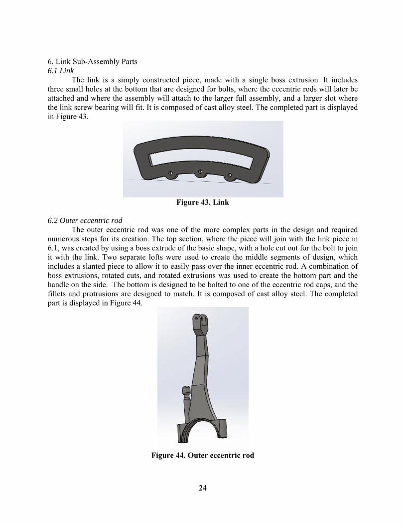
5. Piston Sub-Assembly Parts 5.1 Piston The piston is what incoming steam interacts with inside the cylinder sub-assembly. The piston was created using one extruded boss and two revolved cuts, and it is made out of cast alloy steel. The completed part is shown in Figure 40.
23
Figure 40. Piston
5.2 Piston Rod The piston rod is what was mated into the hinge body of the powertrain sub-assembly to drive it. It is made of cast alloy steel and consists of a single revolved boss feature. The completed part is shown in Figure 41.
Figure 41. Piston rod
5.3 Piston Ring The piston ring fits into the revolved cuts on the piston. Unlike the piston and piston rod, the piston rings are made out of cast iron. The completed part is shown in Figure 42.
Figure 42. Piston ring
24
6. Link Sub-Assembly Parts 6.1 Link The link is a simply constructed piece, made with a single boss extrusion. It includes three small holes at the bottom that are designed for bolts, where the eccentric rods will later be attached and where the assembly will attach to the larger full assembly, and a larger slot where the link screw bearing will fit. It is composed of cast alloy steel. The completed part is displayed in Figure 43.
Figure 43. Link
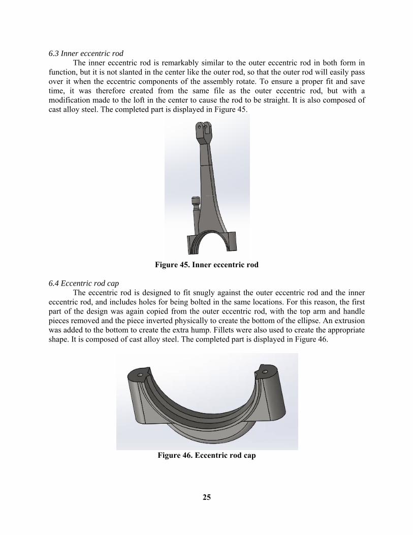
6.2 Outer eccentric rod The outer eccentric rod was one of the more complex parts in the design and required numerous steps for its creation. The top section, where the piece will join with the link piece in 6.1, was created by using a boss extrude of the basic shape, with a hole cut out for the bolt to join it with the link. Two separate lofts were used to create the middle segments of design, which includes a slanted piece to allow it to easily pass over the inner eccentric rod. A combination of boss extrusions, rotated cuts, and rotated extrusions was used to create the bottom part and the handle on the side. The bottom is designed to be bolted to one of the eccentric rod caps, and the fillets and protrusions are designed to match. It is composed of cast alloy steel. The completed part is displayed in Figure 44.
Figure 44. Outer eccentric rod
25
6.3 Inner eccentric rod The inner eccentric rod is remarkably similar to the outer eccentric rod in both form in function, but it is not slanted in the center like the outer rod, so that the outer rod will easily pass over it when the eccentric components of the assembly rotate. To ensure a proper fit and save time, it was therefore created from the same file as the outer eccentric rod, but with a modification made to the loft in the center to cause the rod to be straight. It is also composed of cast alloy steel. The completed part is displayed in Figure 45.
Figure 45. Inner eccentric rod
6.4 Eccentric rod cap The eccentric rod is designed to fit snugly against the outer eccentric rod and the inner eccentric rod, and includes holes for being bolted in the same locations. For this reason, the first part of the design was again copied from the outer eccentric rod, with the top arm and handle pieces removed and the piece inverted physically to create the bottom of the ellipse. An extrusion was added to the bottom to create the extra hump. Fillets were also used to create the appropriate shape. It is composed of cast alloy steel. The completed part is displayed in Figure 46.
Figure 46. Eccentric rod cap
26
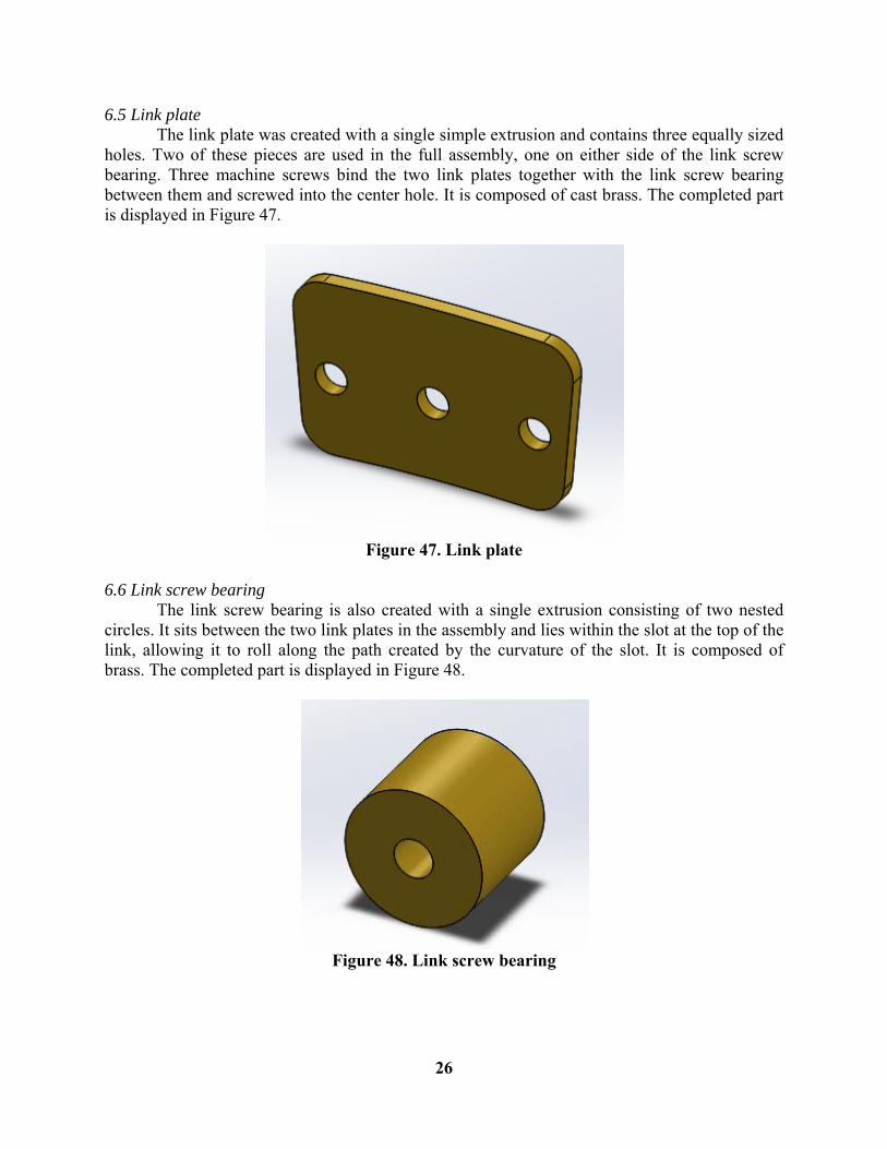
6.5 Link plate The link plate was created with a single simple extrusion and contains three equally sized holes. Two of these pieces are used in the full assembly, one on either side of the link screw bearing. Three machine screws bind the two link plates together with the link screw bearing between them and screwed into the center hole. It is composed of cast brass. The completed part is displayed in Figure 47.
Figure 47. Link plate
6.6 Link screw bearing The link screw bearing is also created with a single extrusion consisting of two nested circles. It sits between the two link plates in the assembly and lies within the slot at the top of the link, allowing it to roll along the path created by the curvature of the slot. It is composed of brass. The completed part is displayed in Figure 48.
Figure 48. Link screw bearing
27
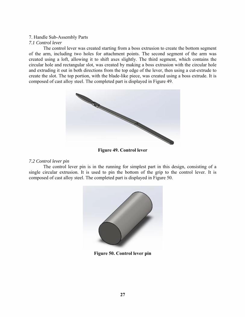
7. Handle Sub-Assembly Parts 7.1 Control lever The control lever was created starting from a boss extrusion to create the bottom segment of the arm, including two holes for attachment points. The second segment of the arm was created using a loft, allowing it to shift axes slightly. The third segment, which contains the circular hole and rectangular slot, was created by making a boss extrusion with the circular hole and extruding it out in both directions from the top edge of the lever, then using a cut-extrude to create the slot. The top portion, with the blade-like piece, was created using a boss extrude. It is composed of cast alloy steel. The completed part is displayed in Figure 49.
Figure 49. Control lever
7.2 Control lever pin The control lever pin is in the running for simplest part in this design, consisting of a single circular extrusion. It is used to pin the bottom of the grip to the control lever. It is composed of cast alloy steel. The completed part is displayed in Figure 50.
Figure 50. Control lever pin
28
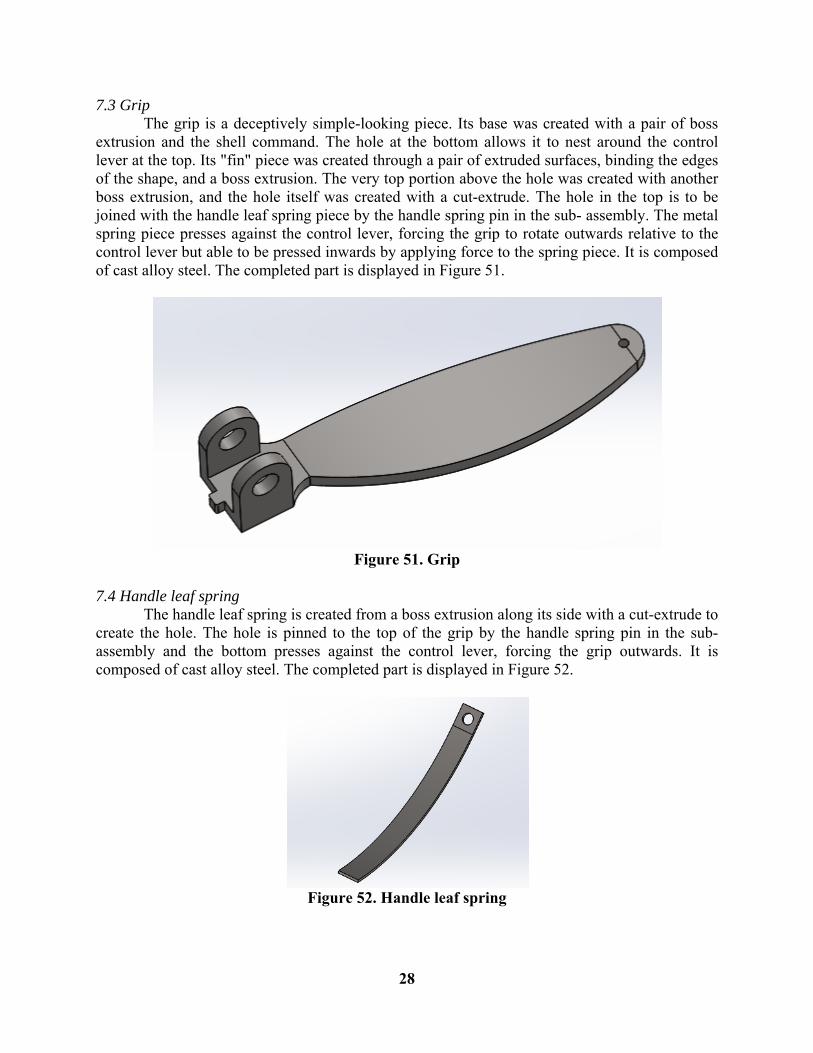
7.3 Grip The grip is a deceptively simple-looking piece. Its base was created with a pair of boss extrusion and the shell command. The hole at the bottom allows it to nest around the control lever at the top. Its "fin" piece was created through a pair of extruded surfaces, binding the edges of the shape, and a boss extrusion. The very top portion above the hole was created with another boss extrusion, and the hole itself was created with a cut-extrude. The hole in the top is to be joined with the handle leaf spring piece by the handle spring pin in the sub- assembly. The metal spring piece presses against the control lever, forcing the grip to rotate outwards relative to the control lever but able to be pressed inwards by applying force to the spring piece. It is composed of cast alloy steel. The completed part is displayed in Figure 51.
Figure 51. Grip
7.4 Handle leaf spring The handle leaf spring is created from a boss extrusion along its side with a cut-extrude to create the hole. The hole is pinned to the top of the grip by the handle spring pin in the sub-assembly and the bottom presses against the control lever, forcing the grip outwards. It is composed of cast alloy steel. The completed part is displayed in Figure 52.
Figure 52. Handle leaf spring
29
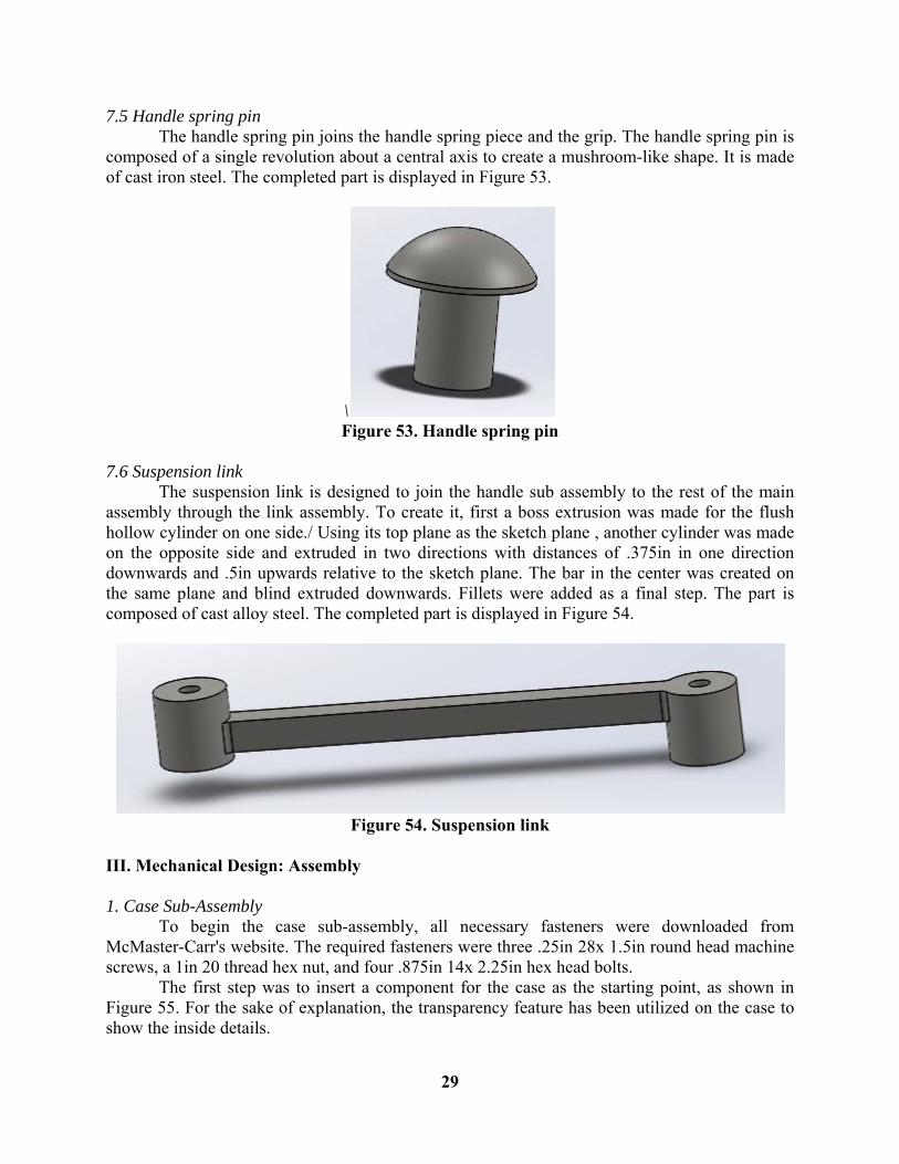
7.5 Handle spring pin The handle spring pin joins the handle spring piece and the grip. The handle spring pin is composed of a single revolution about a central axis to create a mushroom-like shape. It is made of cast iron steel. The completed part is displayed in Figure 53.
\ Figure 53. Handle spring pin
7.6 Suspension link The suspension link is designed to join the handle sub assembly to the rest of the main assembly through the link assembly. To create it, first a boss extrusion was made for the flush hollow cylinder on one side./ Using its top plane as the sketch plane , another cylinder was made on the opposite side and extruded in two directions with distances of .375in in one direction downwards and .5in upwards relative to the sketch plane. The bar in the center was created on the same plane and blind extruded downwards. Fillets were added as a final step. The part is composed of cast alloy steel. The completed part is displayed in Figure 54.
Figure 54. Suspension link
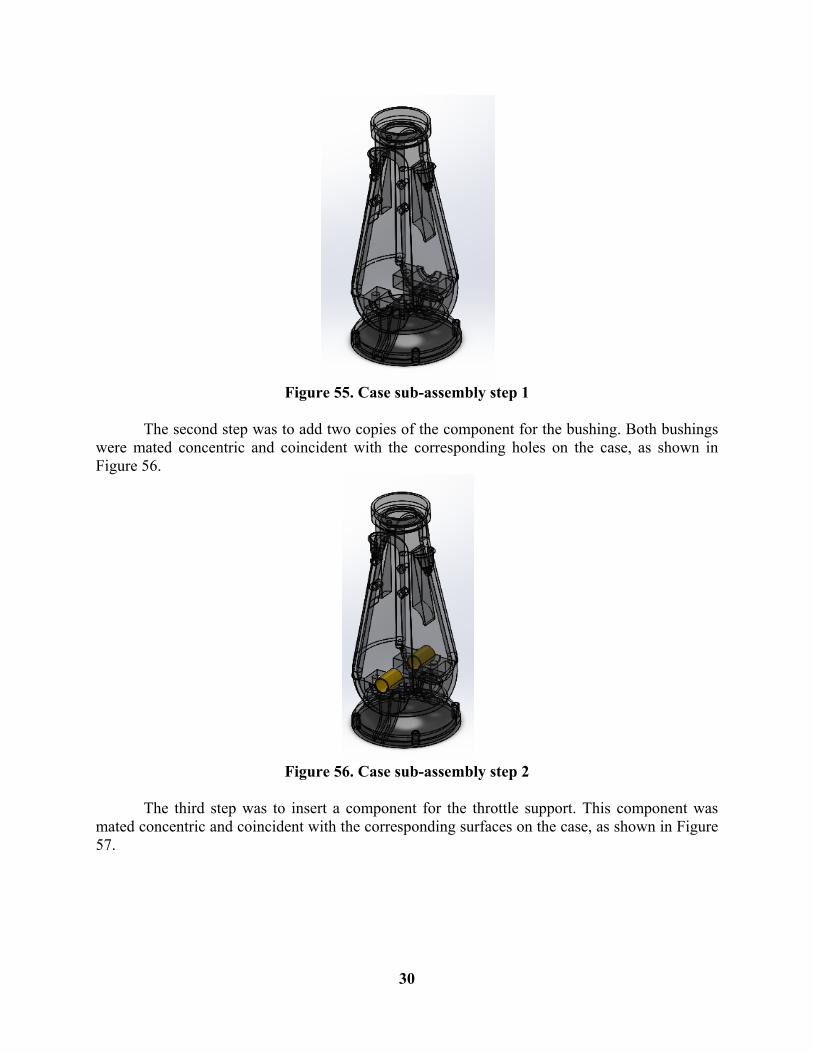
III. Mechanical Design: Assembly 1. Case Sub-Assembly To begin the case sub-assembly, all necessary fasteners were downloaded from McMaster-Carr's website. The required fasteners were three .25in 28x 1.5in round head machine screws, a 1in 20 thread hex nut, and four .875in 14x 2.25in hex head bolts. The first step was to insert a component for the case as the starting point, as shown in Figure 55. For the sake of explanation, the transparency feature has been utilized on the case to show the inside details.
30
Figure 55. Case sub-assembly step 1
The second step was to add two copies of the component for the bushing. Both bushings were mated concentric and coincident with the corresponding holes on the case, as shown in Figure 56.
Figure 56. Case sub-assembly step 2
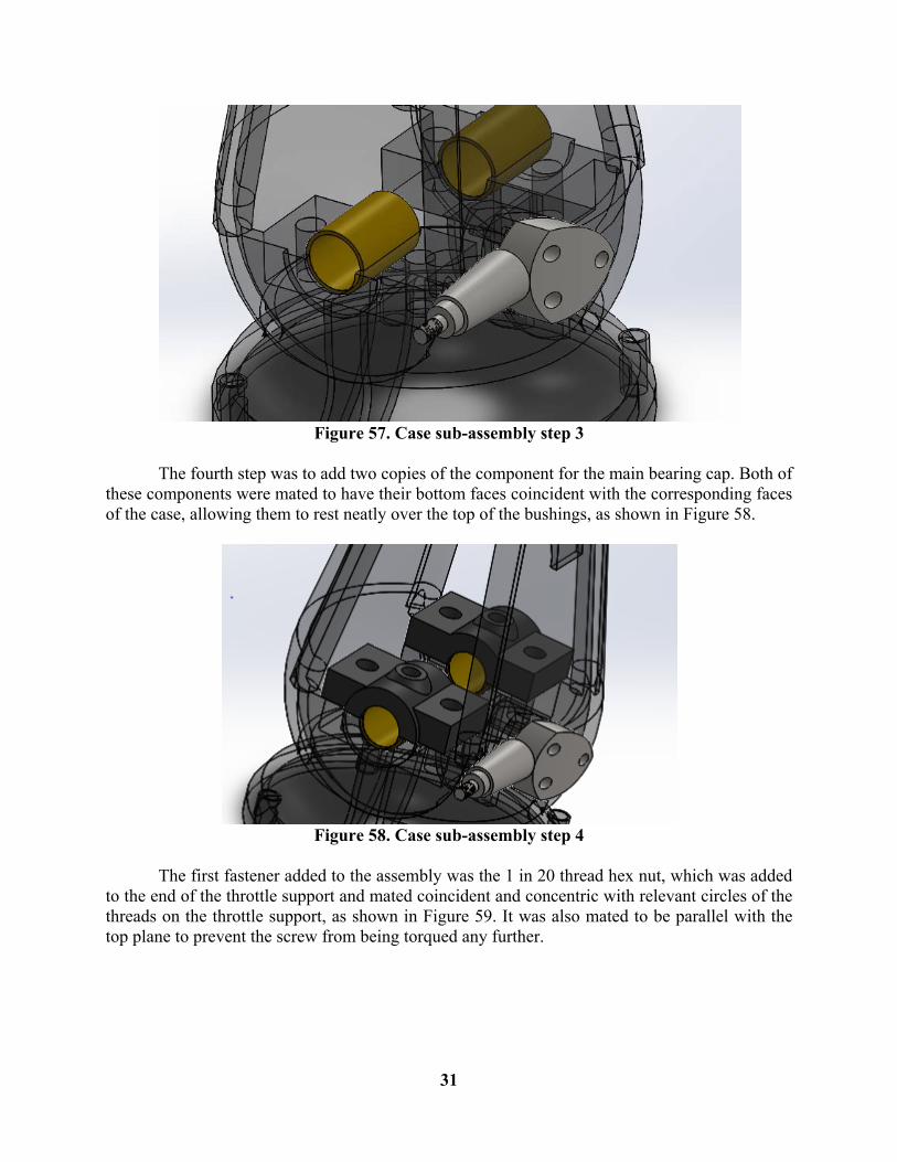
The third step was to insert a component for the throttle support. This component was mated concentric and coincident with the corresponding surfaces on the case, as shown in Figure 57.
31
Figure 57. Case sub-assembly step 3
The fourth step was to add two copies of the component for the main bearing cap. Both of these components were mated to have their bottom faces coincident with the corresponding faces of the case, allowing them to rest neatly over the top of the bushings, as shown in Figure 58.
Figure 58. Case sub-assembly step 4
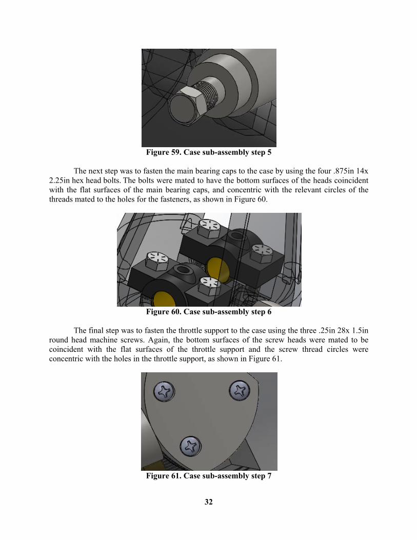
The first fastener added to the assembly was the 1 in 20 thread hex nut, which was added to the end of the throttle support and mated coincident and concentric with relevant circles of the threads on the throttle support, as shown in Figure 59. It was also mated to be parallel with the top plane to prevent the screw from being torqued any further.
32
Figure 59. Case sub-assembly step 5
The next step was to fasten the main bearing caps to the case by using the four .875in 14x 2.25in hex head bolts. The bolts were mated to have the bottom surfaces of the heads coincident with the flat surfaces of the main bearing caps, and concentric with the relevant circles of the threads mated to the holes for the fasteners, as shown in Figure 60.
Figure 60. Case sub-assembly step 6
The final step was to fasten the throttle support to the case using the three .25in 28x 1.5in round head machine screws. Again, the bottom surfaces of the screw heads were mated to be coincident with the flat surfaces of the throttle support and the screw thread circles were concentric with the holes in the throttle support, as shown in Figure 61.
Figure 61. Case sub-assembly step 7
33
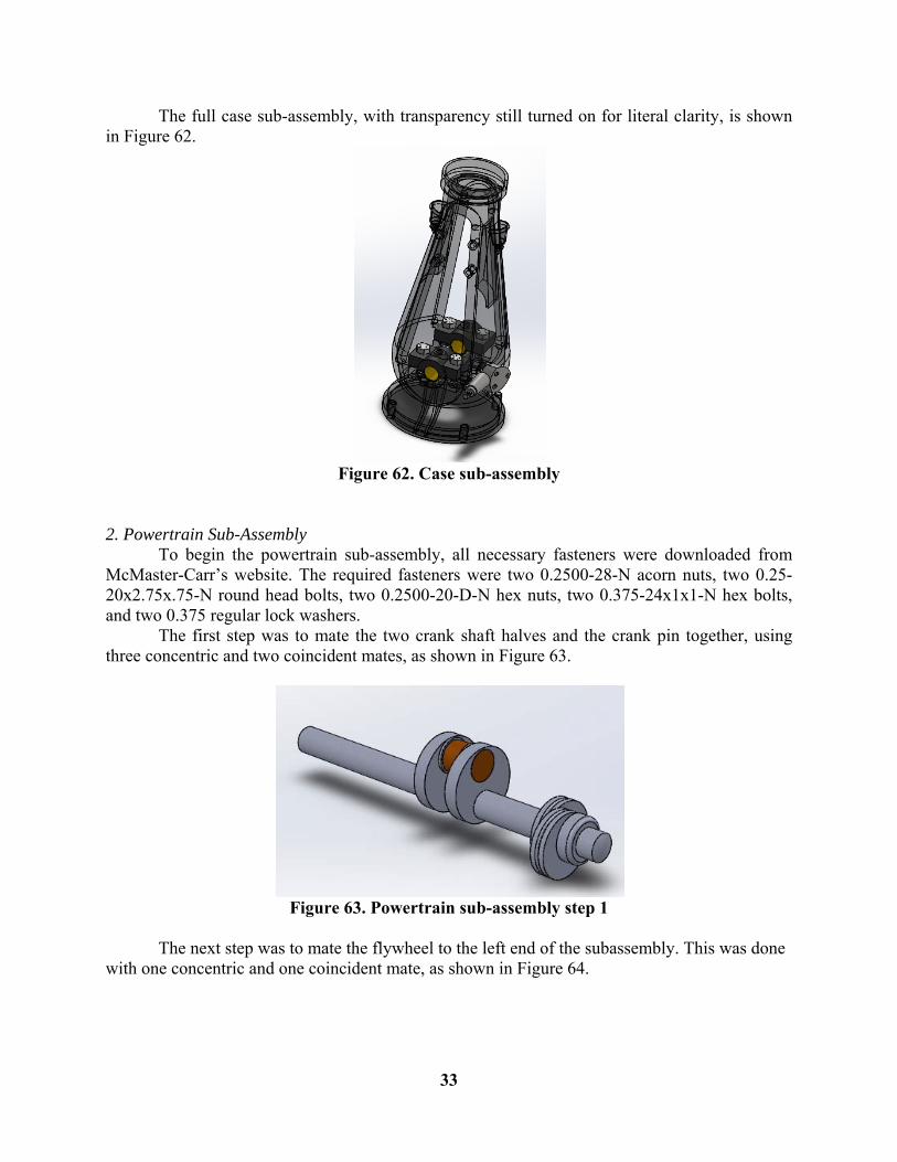
The full case sub-assembly, with transparency still turned on for literal clarity, is shown in Figure 62.
Figure 62. Case sub-assembly
2. Powertrain Sub-Assembly To begin the powertrain sub-assembly, all necessary fasteners were downloaded from McMaster-Carr’s website. The required fasteners were two 0.2500-28-N acorn nuts, two 0.25-20x2.75x.75-N round head bolts, two 0.2500-20-D-N hex nuts, two 0.375-24x1x1-N hex bolts, and two 0.375 regular lock washers. The first step was to mate the two crank shaft halves and the crank pin together, using three concentric and two coincident mates, as shown in Figure 63.
Figure 63. Powertrain sub-assembly step 1
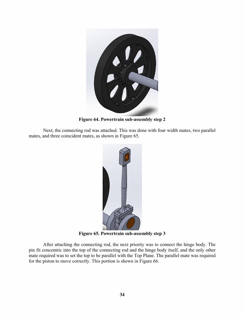
The next step was to mate the flywheel to the left end of the subassembly. This was done with one concentric and one coincident mate, as shown in Figure 64.
34
Figure 64. Powertrain sub-assembly step 2
Next, the connecting rod was attached. This was done with four width mates, two parallel mates, and three coincident mates, as shown in Figure 65.
Figure 65. Powertrain sub-assembly step 3
After attaching the connecting rod, the next priority was to connect the hinge body. The pin fit concentric into the top of the connecting rod and the hinge body itself, and the only other mate required was to set the top to be parallel with the Top Plane. The parallel mate was required for the piston to move correctly. This portion is shown in Figure 66.
35
Figure 66. Powertrain sub-assembly step 4
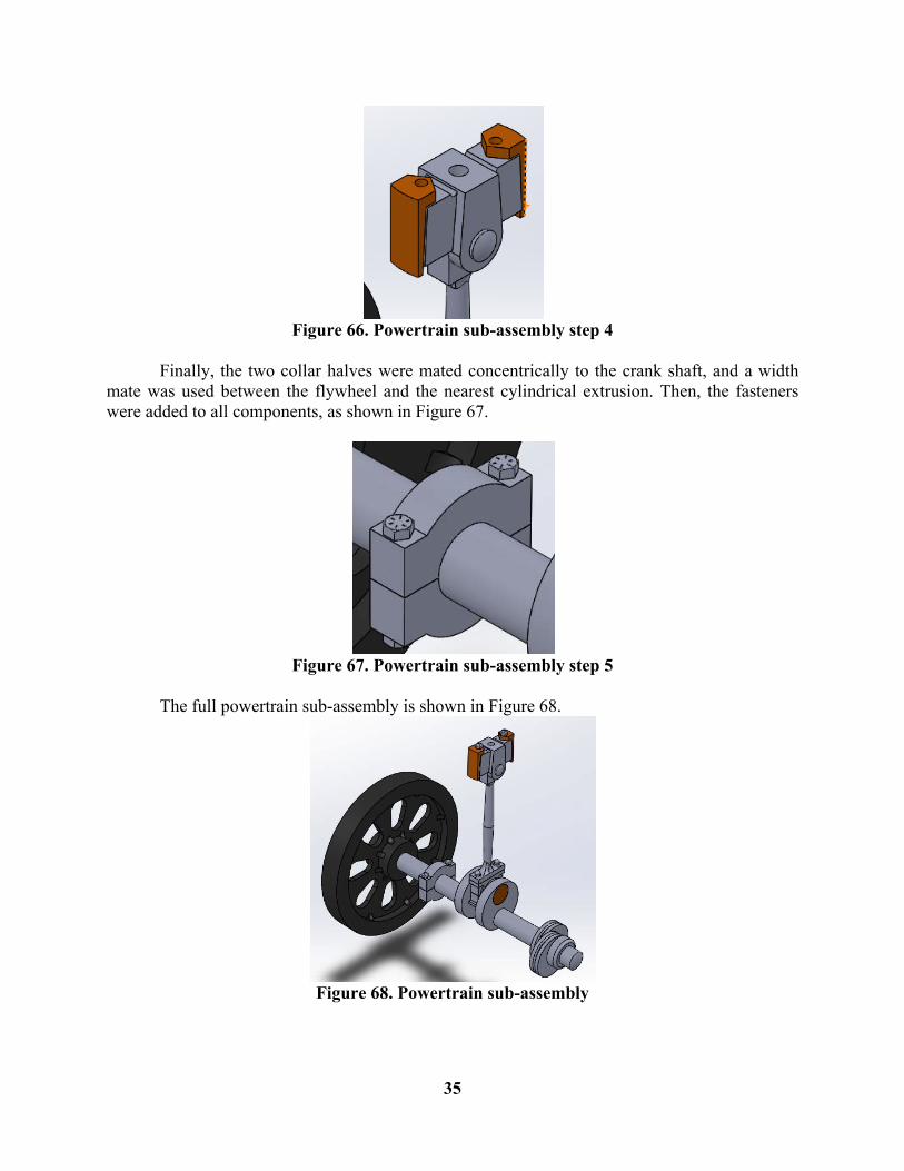
Finally, the two collar halves were mated concentrically to the crank shaft, and a width mate was used between the flywheel and the nearest cylindrical extrusion. Then, the fasteners were added to all components, as shown in Figure 67.
Figure 67. Powertrain sub-assembly step 5
The full powertrain sub-assembly is shown in Figure 68.
Figure 68. Powertrain sub-assembly
36
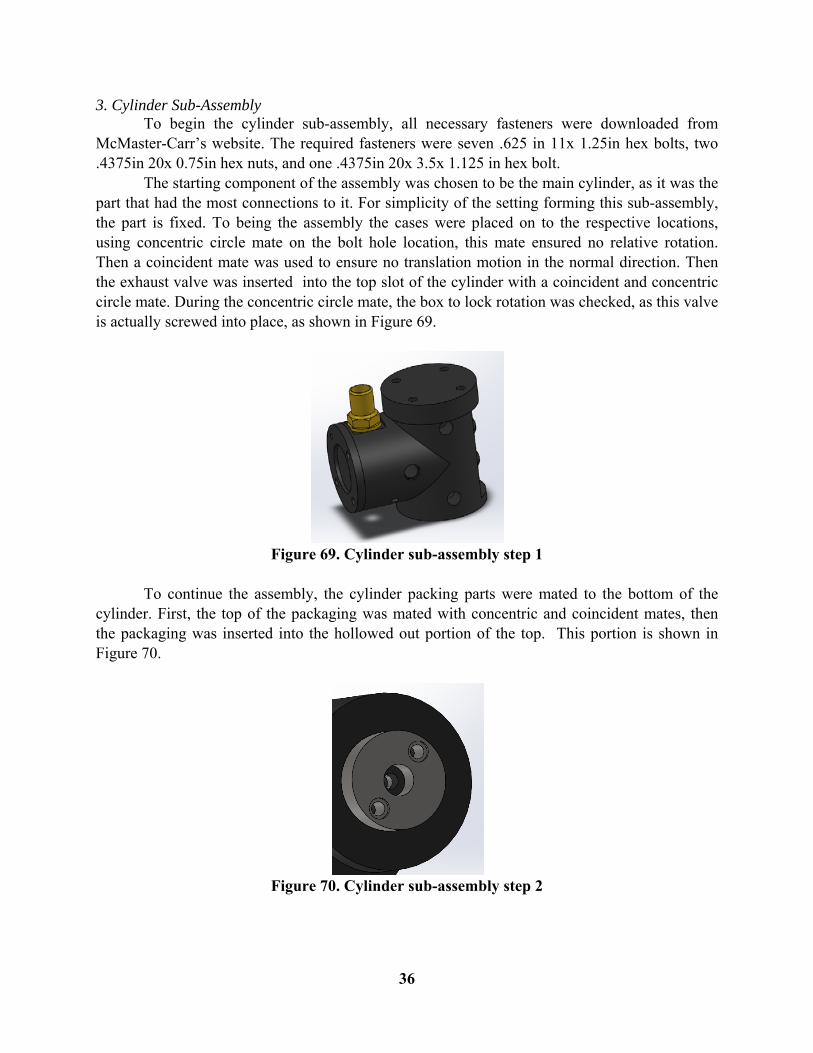
3. Cylinder Sub-Assembly To begin the cylinder sub-assembly, all necessary fasteners were downloaded from McMaster-Carr’s website. The required fasteners were seven .625 in 11x 1.25in hex bolts, two .4375in 20x 0.75in hex nuts, and one .4375in 20x 3.5x 1.125 in hex bolt. The starting component of the assembly was chosen to be the main cylinder, as it was the part that had the most connections to it. For simplicity of the setting forming this sub-assembly, the part is fixed. To being the assembly the cases were placed on to the respective locations, using concentric circle mate on the bolt hole location, this mate ensured no relative rotation. Then a coincident mate was used to ensure no translation motion in the normal direction. Then the exhaust valve was inserted into the top slot of the cylinder with a coincident and concentric circle mate. During the concentric circle mate, the box to lock rotation was checked, as this valve is actually screwed into place, as shown in Figure 69.
Figure 69. Cylinder sub-assembly step 1
To continue the assembly, the cylinder packing parts were mated to the bottom of the cylinder. First, the top of the packaging was mated with concentric and coincident mates, then the packaging was inserted into the hollowed out portion of the top. This portion is shown in Figure 70.
Figure 70. Cylinder sub-assembly step 2
37
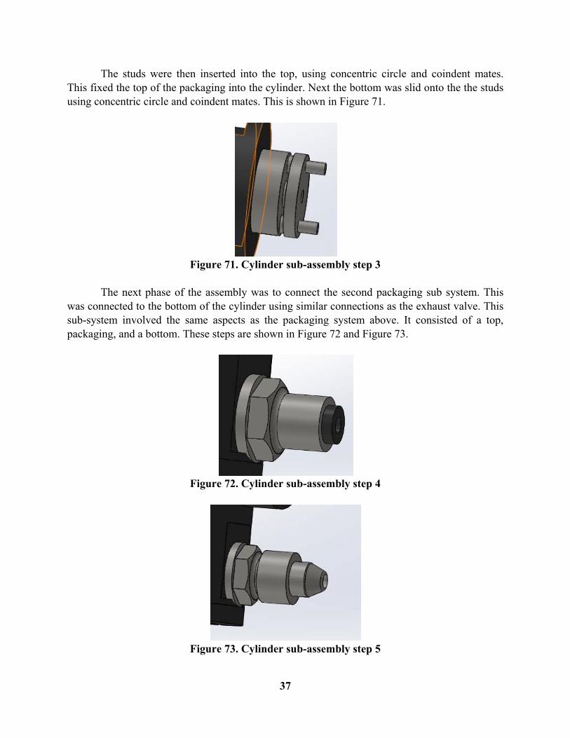
The studs were then inserted into the top, using concentric circle and coindent mates. This fixed the top of the packaging into the cylinder. Next the bottom was slid onto the the studs using concentric circle and coindent mates. This is shown in Figure 71.
Figure 71. Cylinder sub-assembly step 3
The next phase of the assembly was to connect the second packaging sub system. This was connected to the bottom of the cylinder using similar connections as the exhaust valve. This sub-system involved the same aspects as the packaging system above. It consisted of a top, packaging, and a bottom. These steps are shown in Figure 72 and Figure 73.
Figure 72. Cylinder sub-assembly step 4
Figure 73. Cylinder sub-assembly step 5
38
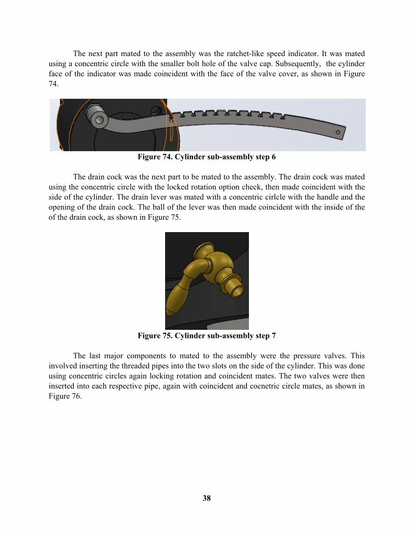
The next part mated to the assembly was the ratchet-like speed indicator. It was mated using a concentric circle with the smaller bolt hole of the valve cap. Subsequently, the cylinder face of the indicator was made coincident with the face of the valve cover, as shown in Figure 74.
Figure 74. Cylinder sub-assembly step 6
The drain cock was the next part to be mated to the assembly. The drain cock was mated using the concentric circle with the locked rotation option check, then made coincident with the side of the cylinder. The drain lever was mated with a concentric cirlcle with the handle and the opening of the drain cock. The ball of the lever was then made coincident with the inside of the of the drain cock, as shown in Figure 75.
Figure 75. Cylinder sub-assembly step 7
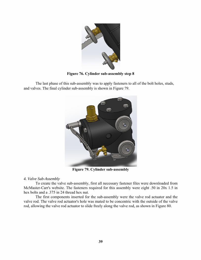
The last major components to mated to the assembly were the pressure valves. This involved inserting the threaded pipes into the two slots on the side of the cylinder. This was done using concentric circles again locking rotation and coincident mates. The two valves were then inserted into each respective pipe, again with coincident and cocnetric circle mates, as shown in Figure 76.
39
Figure 76. Cylinder sub-assembly step 8
The last phase of this sub-assembly was to apply fasteners to all of the bolt holes, studs, and valves. The final cylinder sub-assembly is shown in Figure 79.
Figure 79. Cylinder sub-assembly
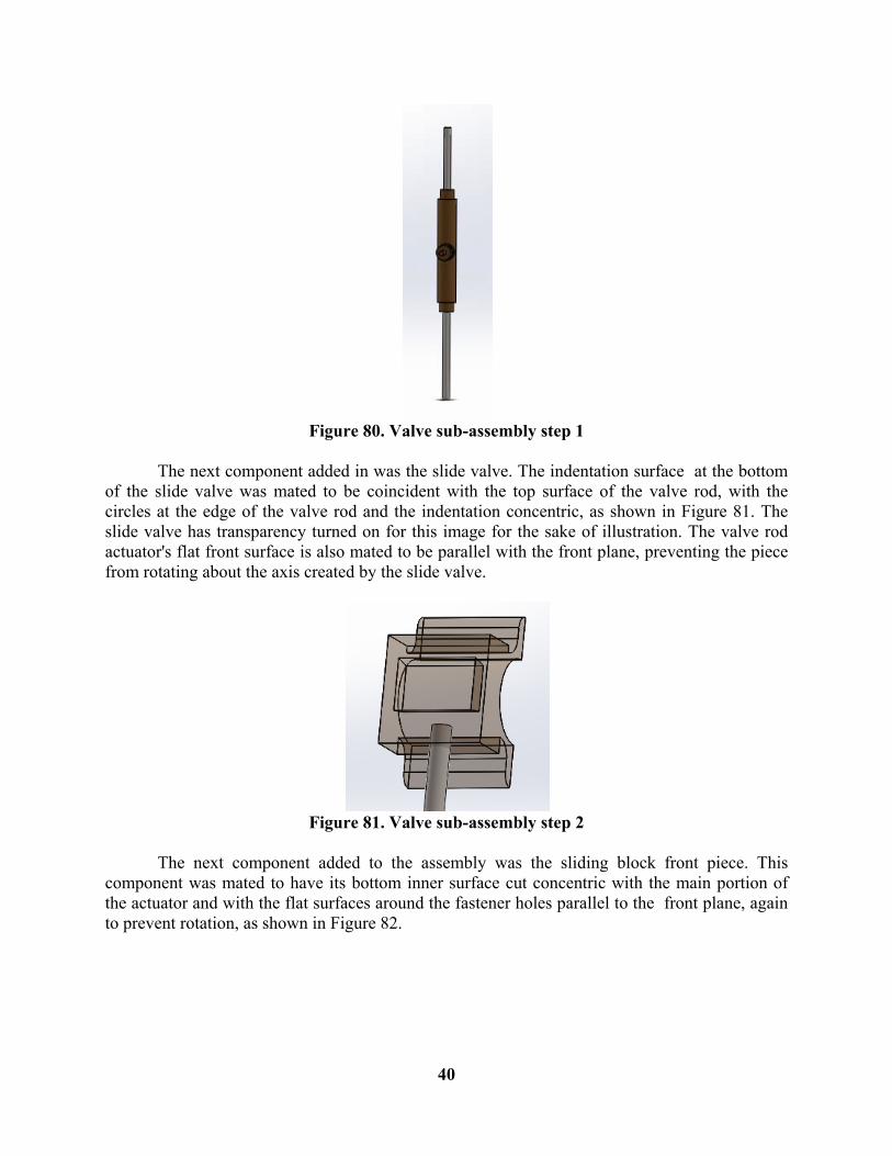
4. Valve Sub-Assembly To create the valve sub-assembly, first all necessary fastener files were downloaded from McMaster-Carr's website. The fasteners required for this assembly were eight .50 in 20x 1.5 in hex bolts and a .375 in 24 thread hex nut. The first components inserted for the sub-assembly were the valve rod actuator and the valve rod. The valve rod actuator's hole was mated to be concentric with the outside of the valve rod, allowing the valve rod actuator to slide freely along the valve rod, as shown in Figure 80.
40
Figure 80. Valve sub-assembly step 1
The next component added in was the slide valve. The indentation surface at the bottom of the slide valve was mated to be coincident with the top surface of the valve rod, with the circles at the edge of the valve rod and the indentation concentric, as shown in Figure 81. The slide valve has transparency turned on for this image for the sake of illustration. The valve rod actuator's flat front surface is also mated to be parallel with the front plane, preventing the piece from rotating about the axis created by the slide valve.
Figure 81. Valve sub-assembly step 2
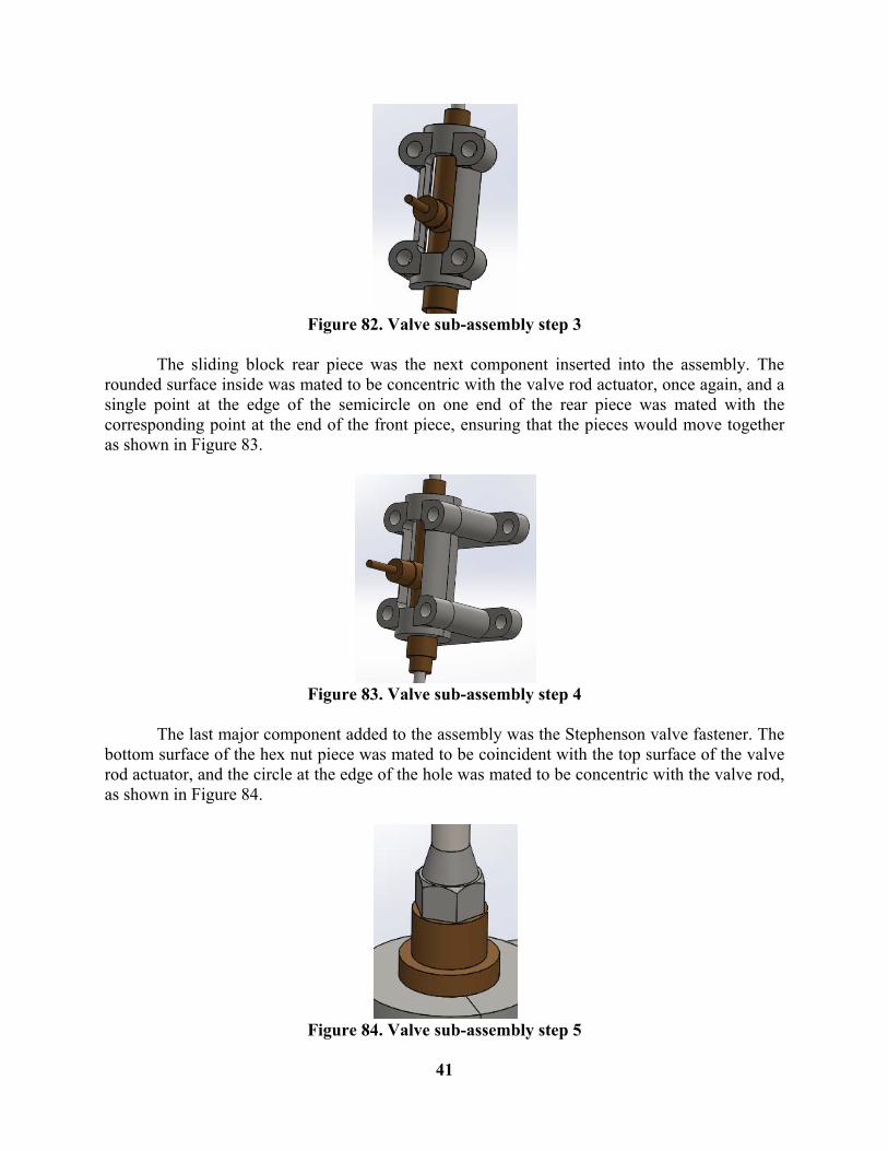
The next component added to the assembly was the sliding block front piece. This component was mated to have its bottom inner surface cut concentric with the main portion of the actuator and with the flat surfaces around the fastener holes parallel to the front plane, again to prevent rotation, as shown in Figure 82.
41
Figure 82. Valve sub-assembly step 3
The sliding block rear piece was the next component inserted into the assembly. The rounded surface inside was mated to be concentric with the valve rod actuator, once again, and a single point at the edge of the semicircle on one end of the rear piece was mated with the corresponding point at the end of the front piece, ensuring that the pieces would move together as shown in Figure 83.
Figure 83. Valve sub-assembly step 4
The last major component added to the assembly was the Stephenson valve fastener. The bottom surface of the hex nut piece was mated to be coincident with the top surface of the valve rod actuator, and the circle at the edge of the hole was mated to be concentric with the valve rod, as shown in Figure 84.
Figure 84. Valve sub-assembly step 5
42
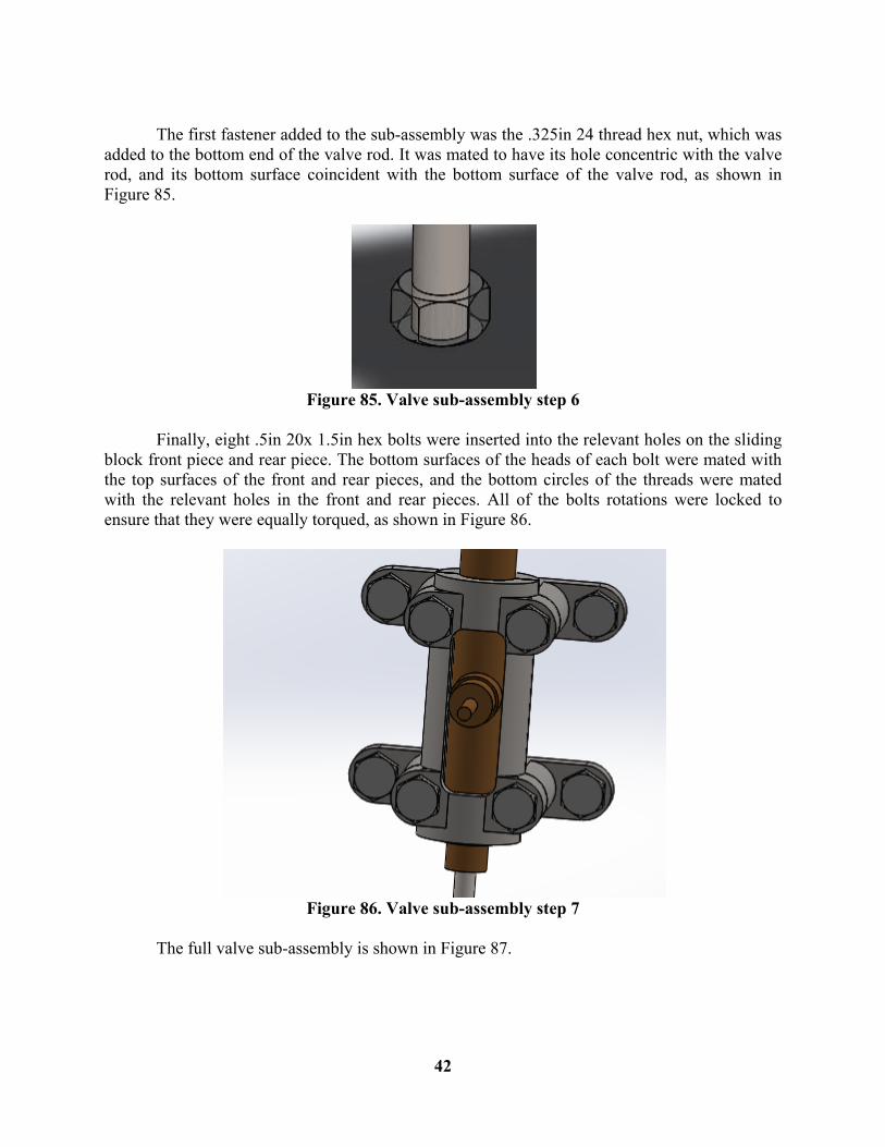
The first fastener added to the sub-assembly was the .325in 24 thread hex nut, which was added to the bottom end of the valve rod. It was mated to have its hole concentric with the valve rod, and its bottom surface coincident with the bottom surface of the valve rod, as shown in Figure 85.
Figure 85. Valve sub-assembly step 6
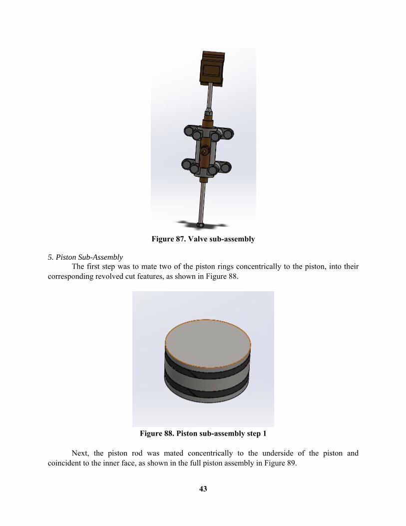
Finally, eight .5in 20x 1.5in hex bolts were inserted into the relevant holes on the sliding block front piece and rear piece. The bottom surfaces of the heads of each bolt were mated with the top surfaces of the front and rear pieces, and the bottom circles of the threads were mated with the relevant holes in the front and rear pieces. All of the bolts rotations were locked to ensure that they were equally torqued, as shown in Figure 86.
Figure 86. Valve sub-assembly step 7
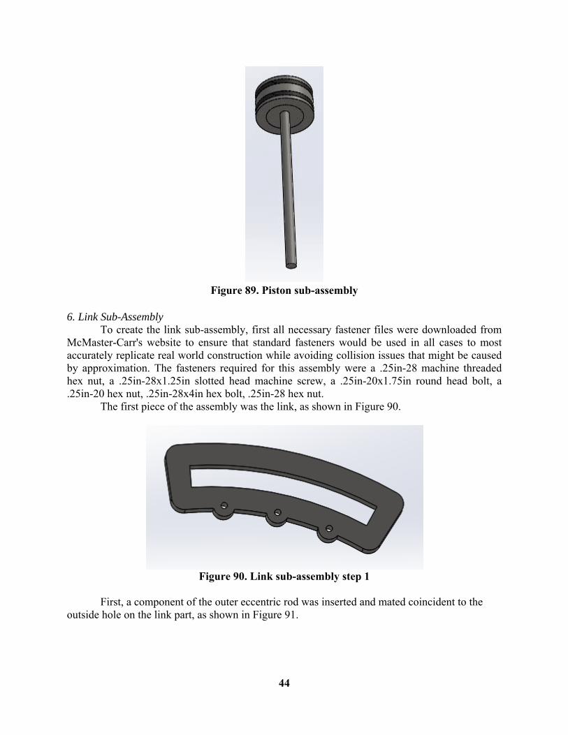
The full valve sub-assembly is shown in Figure 87.
43
Figure 87. Valve sub-assembly
5. Piston Sub-Assembly The first step was to mate two of the piston rings concentrically to the piston, into their corresponding revolved cut features, as shown in Figure 88.
Figure 88. Piston sub-assembly step 1
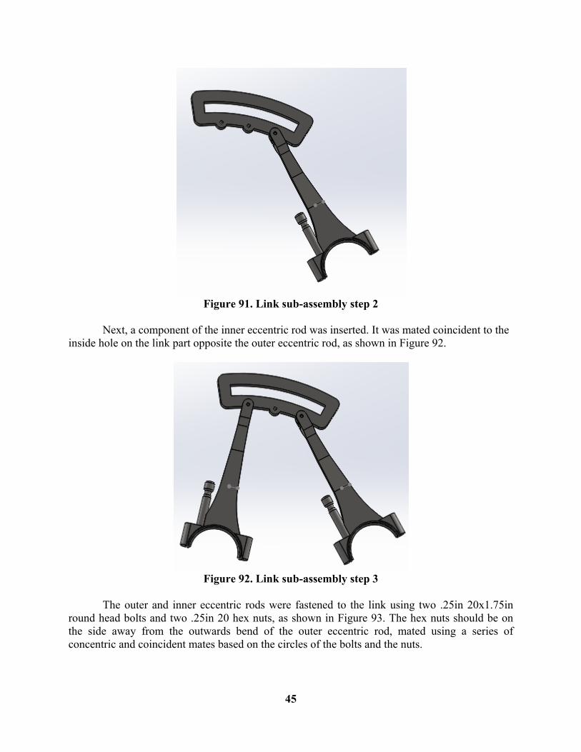
Next, the piston rod was mated concentrically to the underside of the piston and coincident to the inner face, as shown in the full piston assembly in Figure 89.
44
Figure 89. Piston sub-assembly
6. Link Sub-Assembly To create the link sub-assembly, first all necessary fastener files were downloaded from McMaster-Carr's website to ensure that standard fasteners would be used in all cases to most accurately replicate real world construction while avoiding collision issues that might be caused by approximation. The fasteners required for this assembly were a .25in-28 machine threaded hex nut, a .25in-28x1.25in slotted head machine screw, a .25in-20x1.75in round head bolt, a .25in-20 hex nut, .25in-28x4in hex bolt, .25in-28 hex nut. The first piece of the assembly was the link, as shown in Figure 90.
Figure 90. Link sub-assembly step 1
First, a component of the outer eccentric rod was inserted and mated coincident to the outside hole on the link part, as shown in Figure 91.
45
Figure 91. Link sub-assembly step 2
Next, a component of the inner eccentric rod was inserted. It was mated coincident to the inside hole on the link part opposite the outer eccentric rod, as shown in Figure 92.
Figure 92. Link sub-assembly step 3
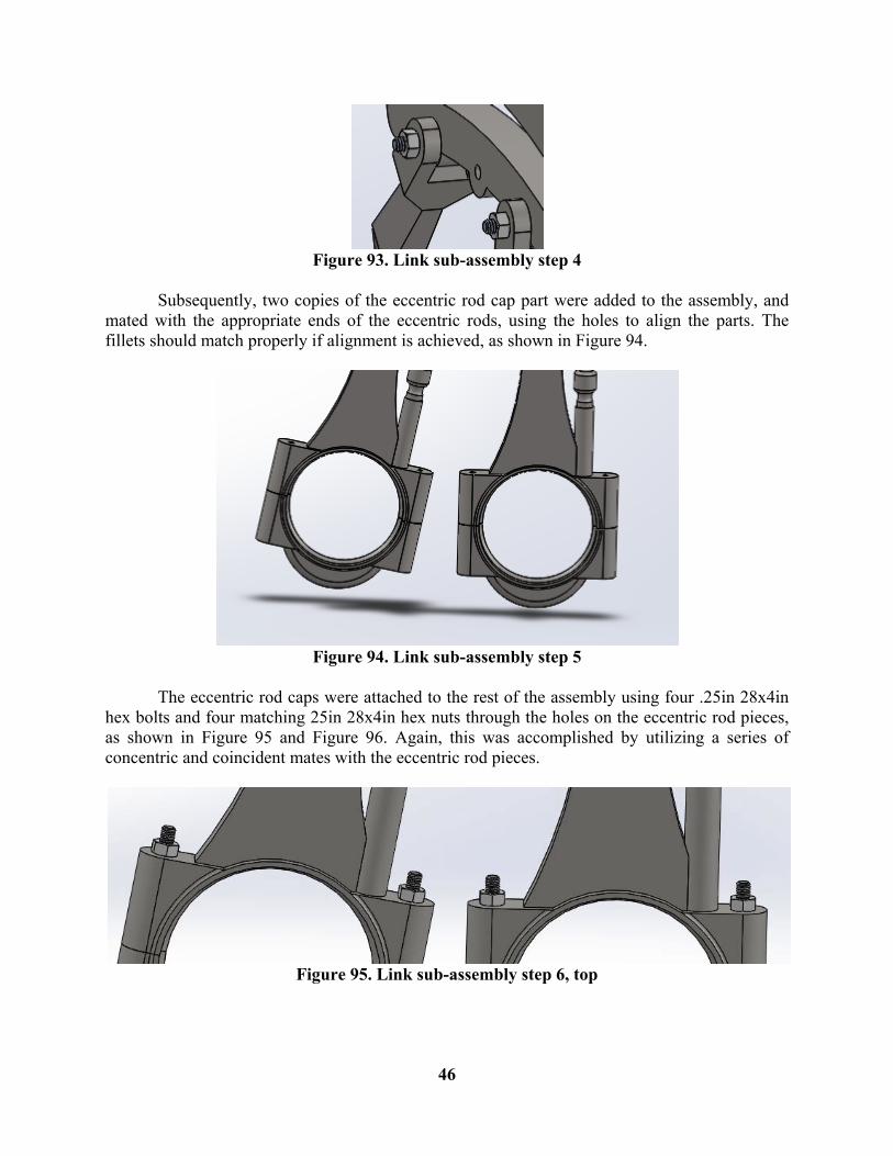
The outer and inner eccentric rods were fastened to the link using two .25in 20x1.75in round head bolts and two .25in 20 hex nuts, as shown in Figure 93. The hex nuts should be on the side away from the outwards bend of the outer eccentric rod, mated using a series of concentric and coincident mates based on the circles of the bolts and the nuts.
46
Figure 93. Link sub-assembly step 4
Subsequently, two copies of the eccentric rod cap part were added to the assembly, and mated with the appropriate ends of the eccentric rods, using the holes to align the parts. The fillets should match properly if alignment is achieved, as shown in Figure 94.
Figure 94. Link sub-assembly step 5
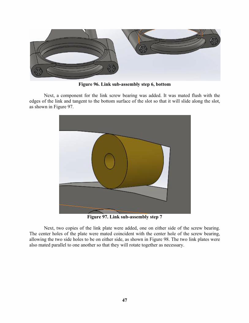
The eccentric rod caps were attached to the rest of the assembly using four .25in 28x4in hex bolts and four matching 25in 28x4in hex nuts through the holes on the eccentric rod pieces, as shown in Figure 95 and Figure 96. Again, this was accomplished by utilizing a series of concentric and coincident mates with the eccentric rod pieces.
Figure 95. Link sub-assembly step 6, top
47
Figure 96. Link sub-assembly step 6, bottom
Next, a component for the link screw bearing was added. It was mated flush with the edges of the link and tangent to the bottom surface of the slot so that it will slide along the slot, as shown in Figure 97.
Figure 97. Link sub-assembly step 7
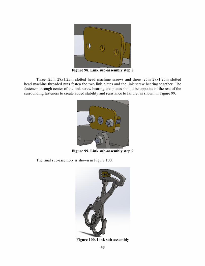
Next, two copies of the link plate were added, one on either side of the screw bearing. The center holes of the plate were mated coincident with the center hole of the screw bearing, allowing the two side holes to be on either side, as shown in Figure 98. The two link plates were also mated parallel to one another so that they will rotate together as necessary.
48
Figure 98. Link sub-assembly step 8
Three .25in 28x1.25in slotted head machine screws and three .25in 28x1.25in slotted head machine threaded nuts fasten the two link plates and the link screw bearing together. The fasteners through center of the link screw bearing and plates should be opposite of the rest of the surrounding fasteners to create added stability and resistance to failure, as shown in Figure 99.
Figure 99. Link sub-assembly step 9
The final sub-assembly is shown in Figure 100.
Figure 100. Link sub-assembly
49
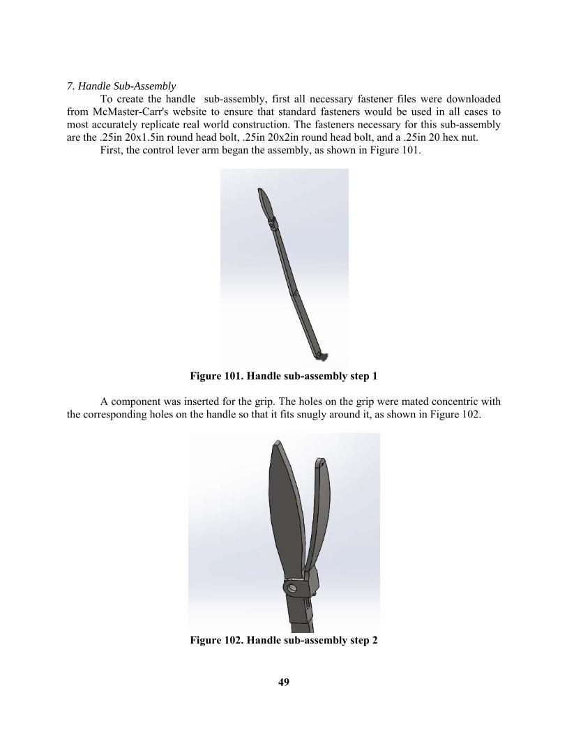
7. Handle Sub-Assembly To create the handle sub-assembly, first all necessary fastener files were downloaded from McMaster-Carr's website to ensure that standard fasteners would be used in all cases to most accurately replicate real world construction. The fasteners necessary for this sub-assembly are the .25in 20x1.5in round head bolt, .25in 20x2in round head bolt, and a .25in 20 hex nut. First, the control lever arm began the assembly, as shown in Figure 101.
Figure 101. Handle sub-assembly step 1
A component was inserted for the grip. The holes on the grip were mated concentric with the corresponding holes on the handle so that it fits snugly around it, as shown in Figure 102.
Figure 102. Handle sub-assembly step 2
50
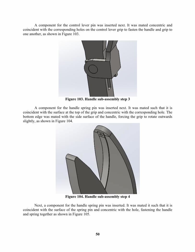
A component for the control lever pin was inserted next. It was mated concentric and coincident with the corresponding holes on the control lever grip to fasten the handle and grip to one another, as shown in Figure 103.
Figure 103. Handle sub-assembly step 3
A component for the handle spring pin was inserted next. It was mated such that it is coincident with the surface at the top of the grip and concentric with the corresponding hole. The bottom edge was mated with the side surface of the handle, forcing the grip to rotate outwards slightly, as shown in Figure 104.
Figure 104. Handle sub-assembly step 4
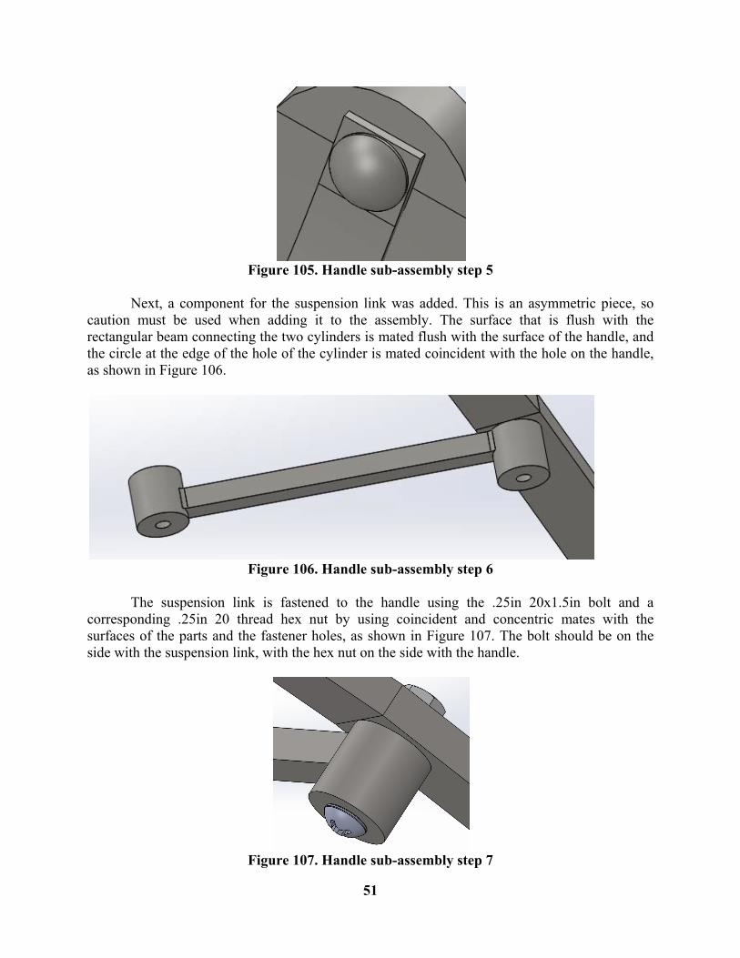
Next, a component for the handle spring pin was inserted. It was mated it such that it is coincident with the surface of the spring pin and concentric with the hole, fastening the handle and spring together as shown in Figure 105.
51
Figure 105. Handle sub-assembly step 5
Next, a component for the suspension link was added. This is an asymmetric piece, so caution must be used when adding it to the assembly. The surface that is flush with the rectangular beam connecting the two cylinders is mated flush with the surface of the handle, and the circle at the edge of the hole of the cylinder is mated coincident with the hole on the handle, as shown in Figure 106.
Figure 106. Handle sub-assembly step 6
The suspension link is fastened to the handle using the .25in 20x1.5in bolt and a corresponding .25in 20 thread hex nut by using coincident and concentric mates with the surfaces of the parts and the fastener holes, as shown in Figure 107. The bolt should be on the side with the suspension link, with the hex nut on the side with the handle.
Figure 107. Handle sub-assembly step 7
52
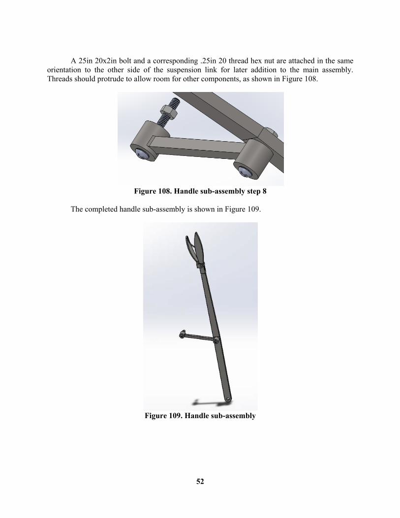
A 25in 20x2in bolt and a corresponding .25in 20 thread hex nut are attached in the same orientation to the other side of the suspension link for later addition to the main assembly. Threads should protrude to allow room for other components, as shown in Figure 108.
Figure 108. Handle sub-assembly step 8
The completed handle sub-assembly is shown in Figure 109.
Figure 109. Handle sub-assembly
53
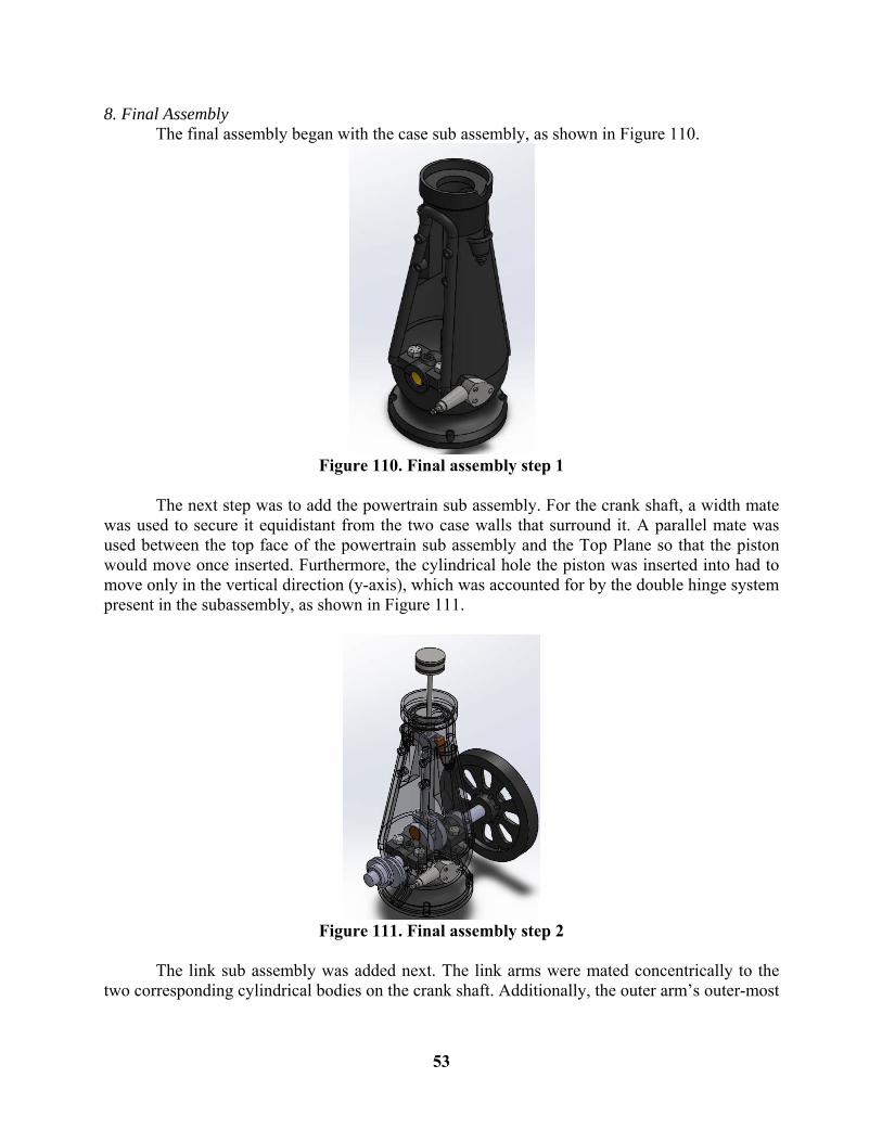
8. Final Assembly The final assembly began with the case sub assembly, as shown in Figure 110.
Figure 110. Final assembly step 1
The next step was to add the powertrain sub assembly. For the crank shaft, a width mate was used to secure it equidistant from the two case walls that surround it. A parallel mate was used between the top face of the powertrain sub assembly and the Top Plane so that the piston would move once inserted. Furthermore, the cylindrical hole the piston was inserted into had to move only in the vertical direction (y-axis), which was accounted for by the double hinge system present in the subassembly, as shown in Figure 111.
Figure 111. Final assembly step 2
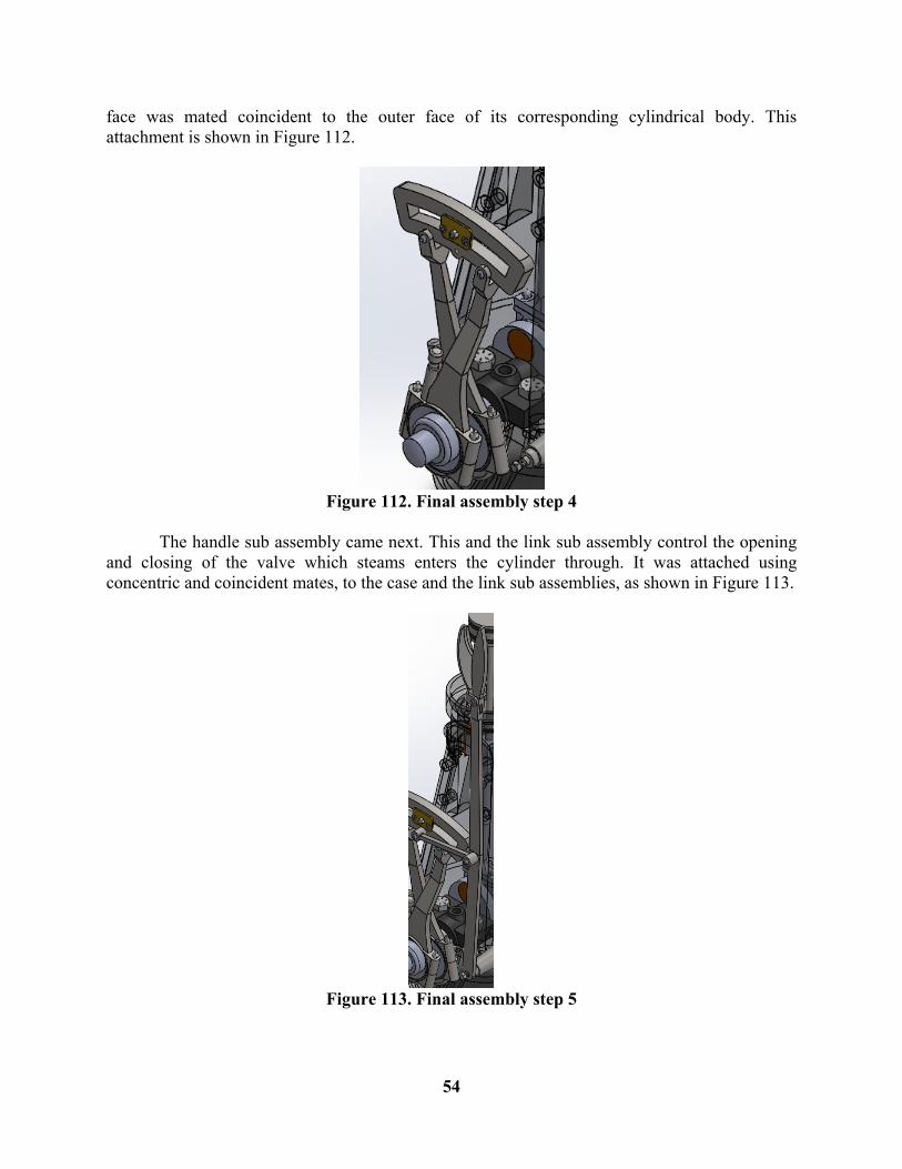
The link sub assembly was added next. The link arms were mated concentrically to the two corresponding cylindrical bodies on the crank shaft. Additionally, the outer arm’s outer-most
54
face was mated coincident to the outer face of its corresponding cylindrical body. This attachment is shown in Figure 112.
Figure 112. Final assembly step 4
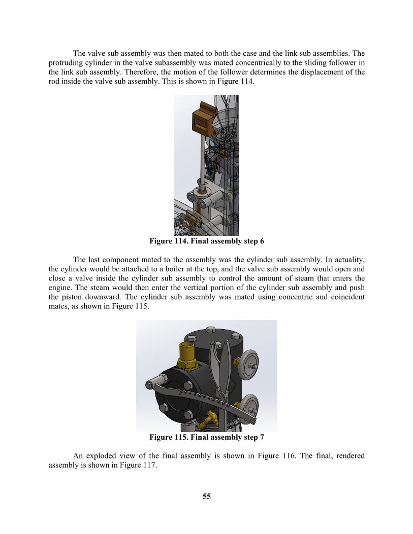
The handle sub assembly came next. This and the link sub assembly control the opening and closing of the valve which steams enters the cylinder through. It was attached using concentric and coincident mates, to the case and the link sub assemblies, as shown in Figure 113.
Figure 113. Final assembly step 5
55
The valve sub assembly was then mated to both the case and the link sub assemblies. The protruding cylinder in the valve subassembly was mated concentrically to the sliding follower in the link sub assembly. Therefore, the motion of the follower determines the displacement of the rod inside the valve sub assembly. This is shown in Figure 114.
Figure 114. Final assembly step 6
The last component mated to the assembly was the cylinder sub assembly. In actuality, the cylinder would be attached to a boiler at the top, and the valve sub assembly would open and close a valve inside the cylinder sub assembly to control the amount of steam that enters the engine. The steam would then enter the vertical portion of the cylinder sub assembly and push the piston downward. The cylinder sub assembly was mated using concentric and coincident mates, as shown in Figure 115.
Figure 115. Final assembly step 7
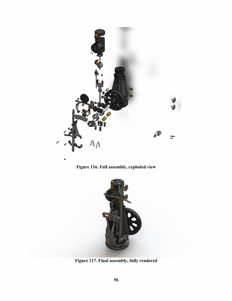
An exploded view of the final assembly is shown in Figure 116. The final, rendered assembly is shown in Figure 117.
56
Figure 116. Full assembly, exploded view
Figure 117. Final assembly, fully rendered
IV. Mech Tincluded were stanbe machimass proaligned to TSolidWowas stucanalysis moved fr
V. Mech Twhich capowertraallow thethrough contains
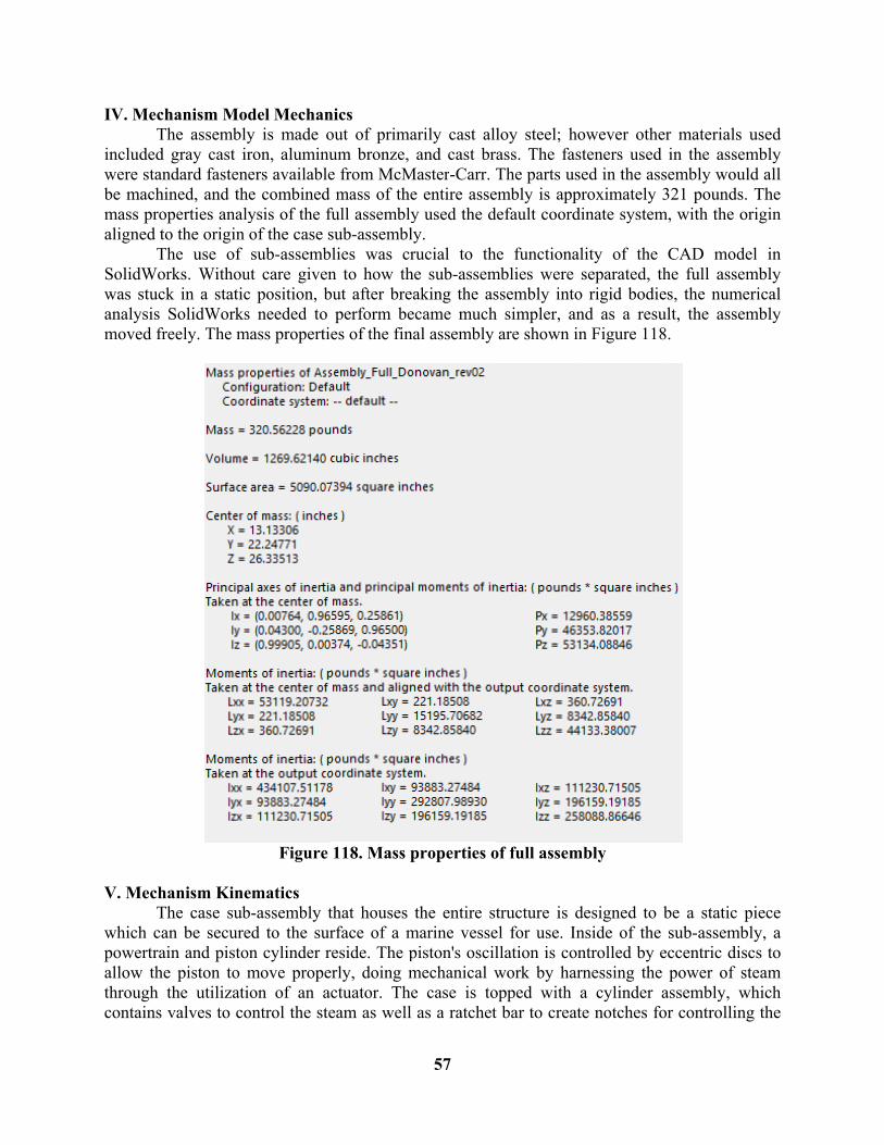
hanism MoThe assembly
gray cast irndard fastenined, and th
operties analyo the origin
The use of rks. Withouk in a staticSolidWorks
reely. The m
hanism KineThe case suban be secureain and pistoe piston to mthe utilizativalves to co
del Mechany is made oron, aluminuers availablee combined ysis of the fof the case ssub-assemb
ut care givenc position, bs needed to
mass properti
Figure
ematics b-assembly ted to the suron cylinder rmove propeion of an aontrol the ste
nics out of primaum bronze, e from McMmass of the
full assemblysub-assemblylies was crn to how thbut after brea
perform bees of the fina
118. Mass p
that houses rface of a mreside. The perly, doing mctuator. Theeam as well
57
arily cast alland cast br
Master-Carr. Te entire assey used the dy. rucial to th
he sub-assemaking the as
ecame muchal assembly
properties o
the entire stmarine vessepiston's oscilmechanical we case is toas a ratchet
loy steel; hoass. The fasThe parts us
embly is appdefault coord
e functionamblies were ssembly intoh simpler, an
are shown in
of full assem
tructure is del for use. Inllation is conwork by haropped with t bar to creat
owever othesteners usedsed in the assproximately dinate system
ality of the separated, t
o rigid bodiend as a resun Figure 118
mbly
designed to nside of the ntrolled by ernessing thea cylinder te notches fo
er materials d in the assesembly wou321 pounds
m, with the o
CAD modthe full assees, the numeult, the asse8.
be a static sub-assemb
eccentric dise power of sassembly, wor controllin
used embly uld all . The
origin
del in embly erical
embly
piece bly, a scs to steam which ng the
58
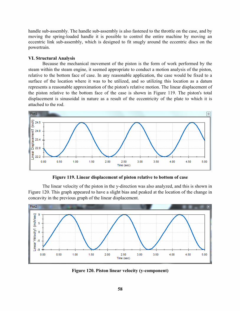
handle sub-assembly. The handle sub-assembly is also fastened to the throttle on the case, and by moving the spring-loaded handle it is possible to control the entire machine by moving an eccentric link sub-assembly, which is designed to fit snugly around the eccentric discs on the powertrain. VI. Structural Analysis Because the mechanical movement of the piston is the form of work performed by the steam within the steam engine, it seemed appropriate to conduct a motion analysis of the piston, relative to the bottom face of case. In any reasonable application, the case would be fixed to a surface of the location where it was to be utilized, and so utilizing this location as a datum represents a reasonable approximation of the piston's relative motion. The linear displacement of the piston relative to the bottom face of the case is shown in Figure 119. The piston's total displacement is sinusoidal in nature as a result of the eccentricity of the plate to which it is attached to the rod.
Figure 119. Linear displacement of piston relative to bottom of case
The linear velocity of the piston in the y-direction was also analyzed, and this is shown in Figure 120. This graph appeared to have a slight bias and peaked at the location of the change in concavity in the previous graph of the linear displacement.
Figure 120. Piston linear velocity (y-component)
59
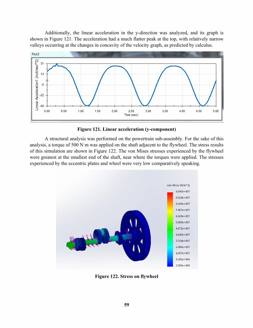
Additionally, the linear acceleration in the y-direction was analyzed, and its graph is shown in Figure 121. The acceleration had a much flatter peak at the top, with relatively narrow valleys occurring at the changes in concavity of the velocity graph, as predicted by calculus.
Figure 121. Linear acceleration (y-component)
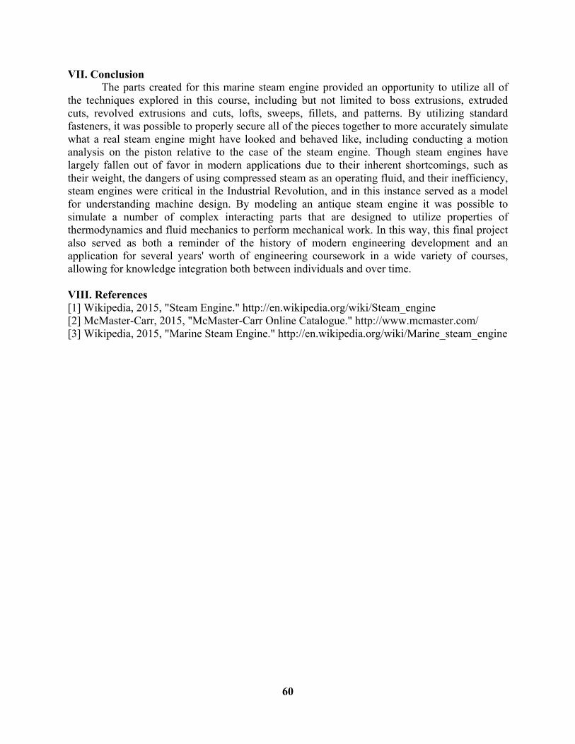
A structural analysis was performed on the powertrain sub-assembly. For the sake of this analysis, a torque of 500 N m was applied on the shaft adjacent to the flywheel. The stress results of this simulation are shown in Figure 122. The von Mises stresses experienced by the flywheel were greatest at the smallest end of the shaft, near where the torques were applied. The stresses experienced by the eccentric plates and wheel were very low comparatively speaking.
Figure 122. Stress on flywheel
60
VII. Conclusion The parts created for this marine steam engine provided an opportunity to utilize all of the techniques explored in this course, including but not limited to boss extrusions, extruded cuts, revolved extrusions and cuts, lofts, sweeps, fillets, and patterns. By utilizing standard fasteners, it was possible to properly secure all of the pieces together to more accurately simulate what a real steam engine might have looked and behaved like, including conducting a motion analysis on the piston relative to the case of the steam engine. Though steam engines have largely fallen out of favor in modern applications due to their inherent shortcomings, such as their weight, the dangers of using compressed steam as an operating fluid, and their inefficiency, steam engines were critical in the Industrial Revolution, and in this instance served as a model for understanding machine design. By modeling an antique steam engine it was possible to simulate a number of complex interacting parts that are designed to utilize properties of thermodynamics and fluid mechanics to perform mechanical work. In this way, this final project also served as both a reminder of the history of modern engineering development and an application for several years' worth of engineering coursework in a wide variety of courses, allowing for knowledge integration both between individuals and over time. VIII. References [1] Wikipedia, 2015, "Steam Engine." http://en.wikipedia.org/wiki/Steam_engine [2] McMaster-Carr, 2015, "McMaster-Carr Online Catalogue." http://www.mcmaster.com/ [3] Wikipedia, 2015, "Marine Steam Engine." http://en.wikipedia.org/wiki/Marine_steam_engine


