APPENDIX A
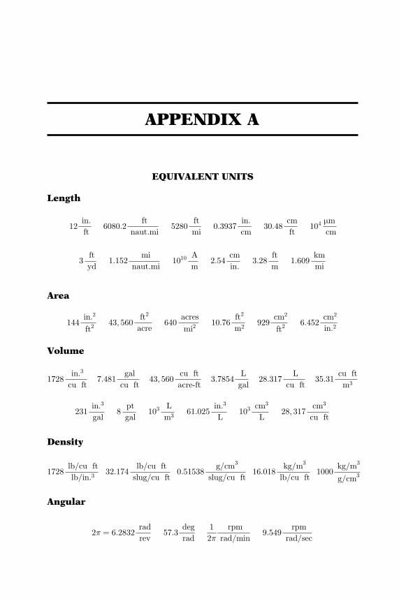
EQUIVALENT UNITS
Length
12in:
ft6080:2
ft
naut:mi5280
ft
mi0:3937
in:
cm30:48
cm
ft104
mmcm
3ft
yd1:152
mi
naut:mi1010
A
m2:54
cm
in:3:28
ft
m1:609
km
mi
Area
144in:2
ft243; 560
ft2
acre640
acres
mi210:76
ft2
m2929
cm2
ft26:452
cm2
in.2
Volume
1728in:3
cu ft7:481
gal
cu ft43; 560
cu ft
acre-ft3:7854
L
gal28:317
L
cu ft35:31
cu ft
m3
231in.3
gal8
pt
gal103
L
m361:025
in.3
L103
cm3
L28; 317
cm3
cu ft
Density
1728lb/cu ft
lb/in.332:174
lb/cu ft
slug/cu ft0:51538
g/cm3
slug/cu ft16:018
kg/m3
lb/cu ft1000
kg/m3
g/cm3
Angular
2� ¼ 6:2832rad
rev57:3
deg
rad
1
2�
rpm
rad/min9:549
rpm
rad/sec
Downloaded From: http://ebooks.asmedigitalcollection.asme.org/ on 09/05/2018 Terms of Use: http://www.asme.org/about-asme/terms-of-use
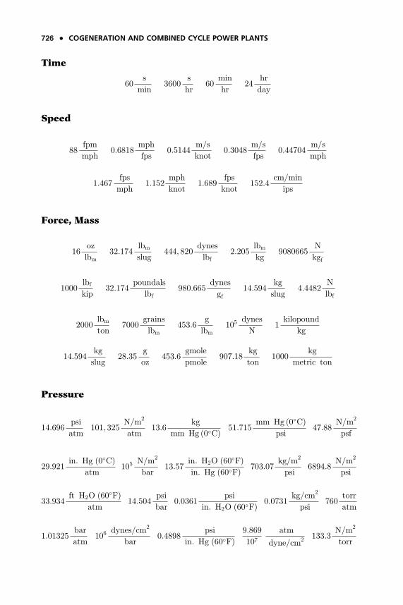
Time
60s
min3600
s
hr60
min
hr24
hr
day
Speed
88fpm
mph0:6818
mph
fps0:5144
m/s
knot0:3048
m/s
fps0:44704
m/s
mph
1:467fps
mph1:152
mph
knot1:689
fps
knot152:4
cm/min
ips
Force, Mass
16oz
lbm32:174
lbmslug
444; 820dynes
lbf2:205
lbmkg
9080665N
kgf
1000lbfkip
32:174poundals
lbf980:665
dynes
gf14:594
kg
slug4:4482
N
lbf
2000lbmton
7000grains
lbm453:6
g
lbm105
dynes
N1kilopound
kg
14:594kg
slug28:35
g
oz453:6
gmole
pmole907:18
kg
ton1000
kg
metric ton
Pressure
14:696psi
atm101; 325
N/m2
atm13:6
kg
mm Hg ð0�CÞ 51:715mm Hg ð0�CÞ
psi47:88
N/m2
psf
29:921in. Hg ð0�CÞ
atm105
N/m2
bar13:57
in: H2O ð60�FÞin: Hg ð60�FÞ 703:07
kg/m2
psi6894:8
N/m2
psi
33:934ft H2O ð60�FÞ
atm14:504
psi
bar0:0361
psi
in. H2O ð60�FÞ 0:0731kg/cm2
psi760
torr
atm
1:01325bar
atm106
dynes/cm2
bar0:4898
psi
in. Hg ð60�FÞ9:869
107atm
dyne/cm2133:3
N/m2
torr
o COGENERATION AND COMBINED CYCLE POWER PLANTS
33:934ft H2O ð60�CÞ
atm760
mm Hg ð0�CÞatm
406:79in. H2O ð39:2�FÞ
atm
0:1dyne/cm2
N/m21:0332
kg/cm2
atm
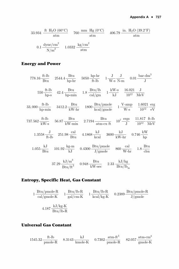
Energy and Power
778:16ft-lb
Btu2544:4
Btu
hp-hr5050
hp-hr
ft-lb1
J
W-s
J
N-m0:01
bar-dm3
J
550ft-lb
hp-s42:4
Btu
hp-min1:8
Btu/lb
cal/gm1kW-s
kJ
16:021
1012J
MeV
33; 000ft-lb
hp-min3412:2
Btu
kW-hr1800
Btu/pmole
kcal/gmole1V-amp
W-s
1:6021
1012erg
eV
737:562ft-lb
kW-s56:87
Btu
kW-min2:7194
Btu
atm-cu ft107
ergs
J
11:817
1012ft-lb
MeV
1:3558J
ft-lb251:98
cal
Btu4:1868
kJ
kcal3600
kJ
kW-hr0:746
kW
hp
1:055kJ
Btu101:92
kg-m
kJ0:4300
Btu/pmole
J/gmole860
cal
W-hr1:8
Btu
chu
37:29kJ/m3
Btu/ft30:948
Btu
kW-sec2:33
kJ/kg
Btu/lbm
Entropy, Specific Heat, Gas Constant
1Btu/pmole-R
cal/gmole-K1
Btu/lb-R
gal/cm-K1
Btu/lb-R
kcal/kg-K0:2389
Btu/pmole-R
J/gmole
4:187kJ/kg-K
Btu/lb-R
Universal Gas Constant
1545:32ft-lb
pmole-R8:3143
kJ
kmole-K0:7302
atm-ft3
pmole-R82:057
atm-cm3
gmole-K
Appendix A o 533726
Downloaded From: http://ebooks.asmedigitalcollection.asme.org/ on 09/05/2018 Terms of Use: http://www.asme.org/about-asme/terms-of-use
Time
60s
min3600
s
hr60
min
hr24
hr
day
Speed
88fpm
mph0:6818
mph
fps0:5144
m/s
knot0:3048
m/s
fps0:44704
m/s
mph
1:467fps
mph1:152
mph
knot1:689
fps
knot152:4
cm/min
ips
Force, Mass
16oz
lbm32:174
lbmslug
444; 820dynes
lbf2:205
lbmkg
9080665N
kgf
1000lbfkip
32:174poundals
lbf980:665
dynes
gf14:594
kg
slug4:4482
N
lbf
2000lbmton
7000grains
lbm453:6
g
lbm105
dynes
N1kilopound
kg
14:594kg
slug28:35
g
oz453:6
gmole
pmole907:18
kg
ton1000
kg
metric ton
Pressure
14:696psi
atm101; 325
N/m2
atm13:6
kg
mm Hg ð0�CÞ 51:715mm Hg ð0�CÞ
psi47:88
N/m2
psf
29:921in. Hg ð0�CÞ
atm105
N/m2
bar13:57
in: H2O ð60�FÞin: Hg ð60�FÞ 703:07
kg/m2
psi6894:8
N/m2
psi
33:934ft H2O ð60�FÞ
atm14:504
psi
bar0:0361
psi
in. H2O ð60�FÞ 0:0731kg/cm2
psi760
torr
atm
1:01325bar
atm106
dynes/cm2
bar0:4898
psi
in. Hg ð60�FÞ9:869
107atm
dyne/cm2133:3
N/m2
torr
532 o COGENERATION AND COMBINED CYCLE POWER PLANTS
33:934ft H2O ð60�CÞ
atm760
mm Hg ð0�CÞatm
406:79in. H2O ð39:2�FÞ
atm
0:1dyne/cm2
N/m21:0332
kg/cm2
atm
Energy and Power
778:16ft-lb
Btu2544:4
Btu
hp-hr5050
hp-hr
ft-lb1
J
W-s
J
N-m0:01
bar-dm3
J
550ft-lb
hp-s42:4
Btu
hp-min1:8
Btu/lb
cal/gm1kW-s
kJ
16:021
1012J
MeV
33; 000ft-lb
hp-min3412:2
Btu
kW-hr1800
Btu/pmole
kcal/gmole1V-amp
W-s
1:6021
1012erg
eV
737:562ft-lb
kW-s56:87
Btu
kW-min2:7194
Btu
atm-cu ft107
ergs
J
11:817
1012ft-lb
MeV
1:3558J
ft-lb251:98
cal
Btu4:1868
kJ
kcal3600
kJ
kW-hr0:746
kW
hp
1:055kJ
Btu101:92
kg-m
kJ0:4300
Btu/pmole
J/gmole860
cal
W-hr1:8
Btu
chu
37:29kJ/m3
Btu/ft30:948
Btu
kW-sec2:33
kJ/kg
Btu/lbm
Entropy, Specific Heat, Gas Constant
1Btu/pmole-R
cal/gmole-K1
Btu/lb-R
gal/cm-K1
Btu/lb-R
kcal/kg-K0:2389
Btu/pmole-R
J/gmole
4:187kJ/kg-K
Btu/lb-R
Universal Gas Constant
1545:32ft-lb
pmole-R8:3143
kJ
kmole-K0:7302
atm-ft3
pmole-R82:057
atm-cm3
gmole-K
Appendix A o 727
Downloaded From: http://ebooks.asmedigitalcollection.asme.org/ on 09/05/2018 Terms of Use: http://www.asme.org/about-asme/terms-of-use
1:9859Btu
pmole-R1:9859
cal
gmole-K10:731
psi-ft3
pmole-R83:143
bar-cm3
gmole-K
8:3143J
gmole-K8:3149� 107
erg
gmole-K0:08206
atm-m3
kgmole-K
0:083143bar-l
gmole-K
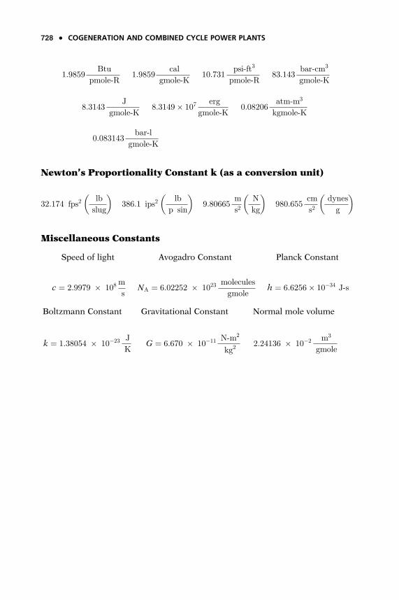
Newton’s Proportionality Constant k (as a conversion unit)
32:174 fps2lb
slug
� �386:1 ips2
lb
p sin
� �9:80665
m
s2N
kg
� �980:655
cm
s2dynes
g
� �
Miscellaneous Constants
Speed of light Avogadro Constant Planck Constant
c ¼ 2:9979 � 108m
sNA ¼ 6:02252 � 1023
molecules
gmoleh ¼ 6:6256� 10�34 J-s
Boltzmann Constant Gravitational Constant Normal mole volume
k ¼ 1:38054 � 10�23 J
KG ¼ 6:670 � 10�11 N-m2
kg22:24136 � 10�2 m3
gmole
o COGENERATION AND COMBINED CYCLE POWER PLANTS728
Downloaded From: http://ebooks.asmedigitalcollection.asme.org/ on 09/05/2018 Terms of Use: http://www.asme.org/about-asme/terms-of-use
APPENDIX B
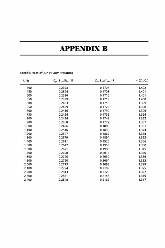
Specific Heat of Air at Low Pressures
T, 8R Cp, Btu/lbm 8R Cv, Btu/lbm 8R � (Cp /Cv)
400 0.2393 0.1707 1.402450 0.2394 0.1708 1.401500 0.2396 0.1710 1.401550 0.2399 0.1713 1.400600 0.2403 0.1718 1.399650 0.2409 0.1723 1.398700 0.2416 0.1730 1.396750 0.2424 0.1739 1.394800 0.2434 0.1748 1.392900 0.2458 0.1772 1.387
1,000 0.2486 0.1800 1.3811,100 0.2516 0.1830 1.3741,200 0.2547 0.1862 1.3681,300 0.2579 0.1894 1.3621,400 0.2611 0.1926 1.3561,500 0.2642 0.1956 1.3501,600 0.2671 0.1985 1.3451,700 0.2698 0.2013 1.3401,800 0.2725 0.2039 1.3361,900 0.2750 0.2064 1.3322,000 0.2773 0.2088 1.3282,100 0.2794 0.2109 1.3252,200 0.2813 0.2128 1.3222,300 0.2831 0.2146 1.3192,400 0.2848 0.2162 1.317
Downloaded From: http://ebooks.asmedigitalcollection.asme.org/ on 09/05/2018 Terms of Use: http://www.asme.org/about-asme/terms-of-use
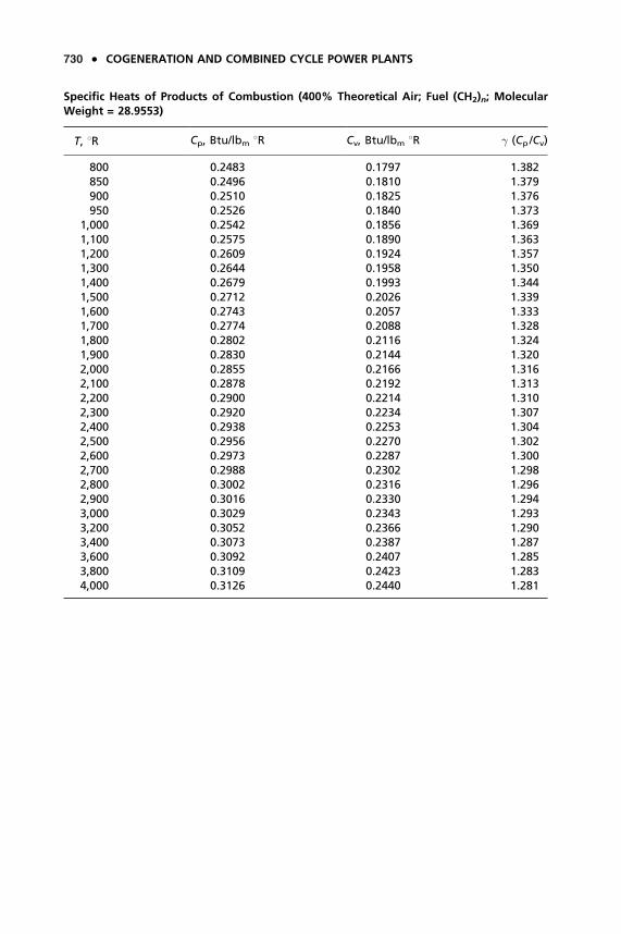
Specific Heats of Products of Combustion (400% Theoretical Air; Fuel (CH2)n; MolecularWeight = 28.9553)
T, 8R Cp, Btu/lbm 8R Cv, Btu/lbm 8R � (Cp /Cv)
800 0.2483 0.1797 1.382850 0.2496 0.1810 1.379900 0.2510 0.1825 1.376950 0.2526 0.1840 1.373
1,000 0.2542 0.1856 1.3691,100 0.2575 0.1890 1.3631,200 0.2609 0.1924 1.3571,300 0.2644 0.1958 1.3501,400 0.2679 0.1993 1.3441,500 0.2712 0.2026 1.3391,600 0.2743 0.2057 1.3331,700 0.2774 0.2088 1.3281,800 0.2802 0.2116 1.3241,900 0.2830 0.2144 1.3202,000 0.2855 0.2166 1.3162,100 0.2878 0.2192 1.3132,200 0.2900 0.2214 1.3102,300 0.2920 0.2234 1.3072,400 0.2938 0.2253 1.3042,500 0.2956 0.2270 1.3022,600 0.2973 0.2287 1.3002,700 0.2988 0.2302 1.2982,800 0.3002 0.2316 1.2962,900 0.3016 0.2330 1.2943,000 0.3029 0.2343 1.2933,200 0.3052 0.2366 1.2903,400 0.3073 0.2387 1.2873,600 0.3092 0.2407 1.2853,800 0.3109 0.2423 1.2834,000 0.3126 0.2440 1.281
o COGENERATION AND COMBINED CYCLE POWER PLANTS730
Downloaded From: http://ebooks.asmedigitalcollection.asme.org/ on 09/05/2018 Terms of Use: http://www.asme.org/about-asme/terms-of-use
BIBLIOGRAPHY
CHAPTER 1 — AN OVERVIEW OF POWER GENERATION
[1] Alderfer, R., Eldridge, M., Starrs, T., 2000, ‘‘Making Connections: Case Studies of Interconnection Barriers and their Impact on Distributed Power Projects,’’ NREL/SR-200-28053.
[2] Boyce, M. P., July 1995, Chapter 1, ‘‘An Overview of Gas Turbines,’’ Gas Turbine Engineering Handbook, 7th Edition, Gulf Publishing Company.
[3] Clean Air Act, 1990, United States Environmental Protection Agency, Washington, D.C.
[4] ‘‘Cogeneration System Package for Micro-Turbines,’’ 2000 Sales Literature-Ingersoll-Rand Corporation, Portsmouth, New Hampshire.
[5] ‘‘Distributed Generation: Understanding The Economics,’’ May/June 2000 Distributed Power.
[6] ‘‘Kyoto Protocol of 1997,’’ 1997, United Nations Framework Convention on Climate Change, N.Y., N.Y., United Nations.
[7] Leo., A. J., Ghezel-Ayagh, H., Sanderson, R., ‘‘Ultra High Efficiency Hybrid Direct Fuel Cell/Turbine Power Plant,’’ ASME Paper No. 2000-GT-0552, ASME.
[8] ‘‘Simple Cycle Micro Turbine Power Generation System,’’ 2000, Sales Literature-Capstone Micro Turbine, Chatsworth, CA.
[9] ‘‘Solid Oxide Fuel Cell, Passing The Learning Curve,’’ May/June 2000 Distributed Power.
CHAPTER 2 — CYCLES
[1] Boyce, M. P., November/December 2000, Advanced Cycles for Combined Cycle Power Plants, Russia Gas Turbo-Technology Publication.
[2] Boyce, M. P., September/October 2000, Turbo-Machinery for the Next Millennium, Russia Gas Turbo-Technology Publication.
[3] Boyce, M. P., Meher-Homji, C. B, Lakshminarasimha, A. N., ‘‘Gas Turbine and Combined Cycle Technologies for Power and Efficiency enhancement in Power Plants,’’ ASME Paper No. 94-GT-435, ASME.
[4] Boyce, M. P., July 1995, Chapter 2, ‘‘Theoretical and Actual Cycle Analysis,’’ Gas Turbine Engineering Handbook, 7th Edition, Gulf Publishing Company.
Downloaded From: http://ebooks.asmedigitalcollection.asme.org/ on 09/05/2018 Terms of Use: http://www.asme.org/about-asme/terms-of-use
732 • COGENERATION AND COMBINED CYCLE POWER PLANTS
[5] Chodkiewicz, R., Porochnicki, J., Potapczyk, A., 1998, ‘‘Electric Power And Nitric Acid Coproduction — A New Concept In Reducing The Energy Costs.’’ Powergen Europe’98, Milan, Italy, Vol. iii, pp. 611-625.
[6] Chodkiewicz, R., ‘‘A Recuperated Gas Turbine Incorporating External Heat Sources in the Combined Gas-Steam Cycle,’’ ASME Paper No. 2000-GT- 0593, ASME.
[7] Holden, P., Moen, D., DeCorso, M., ‘‘Alabama Electric Cooperative Compressed Air Energy Storage (CAES) Plant Improvements,’’ ASME Paper No. 2000-GT-0595, ASME.
[8] Kehlhofer, R. H., et. al., 1999, Combined Cycle Gas & Steam Turbine Power Plants, 2nd Edition, PennWell, Tulsa, Oklahoma.
[9] Lane, A. W., Hoffman, P. A., 1998, ‘‘The U.S. Dep. of Energy Advanced Turbine System. Program,’’ ISROMAC-7, Hawaii, D. O. E.
[10] Miller, H. F., 1989, Blade Erosion — FCCU Power Recovery Expanders, D-R Turbo Products Division, Olean, N.Y.
[11] Nakhamkin, M., ‘‘Increasing Gas Turbine or Combined Cycle Power Production With Compressed Air to Meet Peak Power Demands,’’ ASME Paper No. 2000-GT-0596, ASME.
[12] Ram, N., ‘‘The Single-Shaft Combined Cycle Myth,’’ ASME Paper No. 2000-GT-0594, ASME.
[13] Wieler, C. L., 1998, WR-21 Intercooled Recuperated Gas Turbine, http://www. Gas-Turbines.Com.Randd/Icr-Wrds.Htm.
[14] Ullman Encyclopaedia of Industrial Chemistry, 1991, Vol. A17.
CHAPTER 3 — PERFORMANCE AND MECHANICAL EQUIPMENT STANDARDS
[1] ANSI/API, August 1995, Centrifugal Pumps for Petroleum, Heavy Duty Chemical and Gas Industry Services, 8th Edition, API Std 610, API.
[2] ANSI/API, November 1993, Vibration, Axial-Position, and Bearing-Tempera-ture Monitoring Systems, 3rd Edition, API Std 670, API.
[3] API, January 1995, Heat Recovery Steam Generators, 1st Edition, Publication 534, API.
[4] API, May 1997, Fired Heaters & Steam Generators, 1st Edition, RP 556, API.[5] API, June 1997, General Purpose Steam Turbines for Petroleum, Chemical,
and Gas Industry Services, 4th Edition, API Std 611, API.[6] API, June 1995, Special Purpose Gear Units for Petroleum, Chemical and Gas
Industry Services, 4th Edition, API Std 613, API.[7] API, April 1999, Lubrication, Shaft-Sealing, and Control-Oil Systems and
Auxiliaries for Petroleum, Chemical and Gas Industry Services, 4th Edition, API Std 614, API.
[8] API, August 1998, Gas Turbines for the Petroleum, Chemical and Gas Industry Services, 4th Edition, API Std 616, API.
Downloaded From: http://ebooks.asmedigitalcollection.asme.org/ on 09/05/2018 Terms of Use: http://www.asme.org/about-asme/terms-of-use
Bibliography • 733
[9] API, February 1995, Centrifugal Compressors for Petroleum, Chemical and Gas Industry Services, 6th Edition, API Std 617, API.
[10] API, June 1995, Reciprocating Compressors for Petroleum, Chemical and Gas Industry Services, 4th Edition, API Std 618, API.
[11] API, June 1997, Rotary-Type Positive Displacement Compressors for Petroleum, Chemical, and Gas Industry Services, 3rd Edition, API Std 619, API.
[12] API, October 1998, Special Purpose Couplings for Petroleum Chemical and Gas Industry Services, 3rd Edition, API Std 671, API.
[13] API, September 1996, Packaged, Integrally Geared Centrifugal Air Compres-sors for Petroleum, Chemical, and Gas Industry Services, 3rd Edition, API Std 672, API.
[14] API, July 1997 (Reaffirmed March 2000), General-Purpose Gear Units for Petroleum, Chemical and Gas Industry Services, 2nd Edition, API Std 677, API.
[15] API, February 1996, Liquid Ring Vacuum Pumps and Compressors, 1st Edition, API Std 681, API.
[16] ASME, 1977 (Reaffirmed 1997), Basic Gas Turbines, B133.2, ASME. [17] ASME, 1978 (Reaffirmed 1997), Gas Turbine Control And Protection Systems,
B133.4, ASME. [18] ASME, 1985 (Reaffirmed 1992), Gas Turbine Fuels, B133.7M, ASME. [19] ASME, 1977 (Reaffirmed 1989), Gas Turbine Installation Sound Emissions,
B133.8, ASME. [20] ASME, 1994, Measurement Of Exhaust Emissions From Stationary Gas
Turbine Engines, B133.9, ASME. [21] ASME, 1981 (Reaffirmed 1994), Procurement Standard For Gas Turbine
Auxiliary Equipment, B133.3, ASME. [22] ASME, 1978 (Reaffirmed 1997), Procurement Standard For Gas Turbine
Electrical Equipment, B133.5, ASME. [23] ASME, 1997, Performance Test Code on Atmospheric Water Cooling
Equipment, ASME PTC 23, ASME. [24] ASME, 1981 (Reaffirmed 1992), Performance Test Code on Gas Turbine Heat
Recovery Steam Generators, ASME PTC 4.4, ASME. [25] ASME, 1997, Performance Test Code on Gas Turbines, ASME PTC 22, ASME. [26] ASME, 1996, Performance Test Code on Overall Plant Performance, ASME
PTC 46, ASME. [27] ASME, 1983, Performance Test Code on Steam Condensing Apparatus, ASME
PTC 12.2, ASME.[28] ASME, 1996, Performance Test Code on Steam Turbines, ASME PTC 6,
ASME. [29] ASME, 1988, Performance Test Code on Test Uncertainty: Instruments and
Apparatus, ASME PTC 19.1, ASME.[30] ISO 10436:1993 Petroleum and Natural Gas Industries — General Purpose
Steam Turbine for Refinery Service, 1st Edition, ISO.
Downloaded From: http://ebooks.asmedigitalcollection.asme.org/ on 09/05/2018 Terms of Use: http://www.asme.org/about-asme/terms-of-use
734 • COGENERATION AND COMBINED CYCLE POWER PLANTS
[31] ISO, 1983, Natural Gas — Calculation of Calorific Value, Density and Relative Density, ISO 6976-(E), International Organization for Standardization.
[32] Table of Physical Constants of Paraffin Hydrocarbons and other components of Natural Gas — Gas Producers Association Standard 2145-94.
CHAPTER 4 — AN OVERVIEW OF GAS TURBINES
[1] Abidat, C., Baines, N. C., Firth, M. R., 1992, ‘‘Design of a highly loaded mixed flow turbine,’’ Proc. Inst. Mechanical Engineers, Journal Power 8 Energy, 206:95-107.
[2] Anderson, R. J., Ritter, W. K., Dildine, D. M., 1947, ‘‘An Investigation of the Effect of Blade Curvature on Centrifugal Impeller Performance,’’ NACA TN-1313.
[3] Arcoumanis, C., Martinez-Botas, R. F., Nouri, J. M., Su, C. C., 1997. ‘‘Performance and exit flow characteristics of mixed flow turbines,’’ International Journal of Rotating Machinery, 3(4):277-293.
[4] Baines, N. A., Hajilouy-Benisi, A., Yeo, J. H., 1994, ‘‘The pulse flow performance and modeling of radial inflow turbines.’’ IMechE, Paper No. a405/017.
[5] Balje, O. E., Binsley, R. L., 1960, ‘‘Axial Turbine Performance Evalua-tion,’’ Journal of Engineering for Power, ASME Transactions, 90A:217-232, ASME.
[6] Balje, O. E., 1964, ‘‘A Study of Reynolds Number Effects in Turbomachin-ery,’’ Journal of Engineering for Power, ASME Transactions, 86(A):227, ASME.
[7] Balje, O. E., 1968, ‘‘Axial Cascade Technology and Application to Flow Path Designs,’’ Journal of Engineering for Power, ASME Transactions, 90A:309-340, ASME.
[8] Balje, O.E., 1952, ‘‘A Contribution to the Problem of Designing Radial Turbomachines,’’ Transactions of the ASME, 74:451, ASME.
[9] Ballal, D. R., Lefebvre, A. H., ‘‘A Proposed Method for Calculating Film Cooled Wall Temperatures in Gas Turbine Combustor Chambers,’’ ASME Paper No. 72-WA/HT-24, ASME.
[10] Bammert, K., Rautenberg, M., ‘‘On the Energy Transfer in Centrifugal Compressors,’’ ASME Paper No. 74-GT-121, ASME.
[11] Barker, T., Jan/Feb 1995, ‘‘Siemens’ New Generation,’’ Turbomachinery International.
[12] Behning, F. P., Schum, H. J., Szanca, E. M., 1971, ‘‘Cold-Air Investigation of a Turbine with Transpiration-Cooled Stator Blades, IV-Stage Performance with Wire-Mesh Shell Blading,’’ NASA, TM X-2176, NASA.
[13] Benign, F. O. P., Rust, H. O. W., Jr., Moffitt, T. P., 1971, ‘‘Cold-Air Investigation of a Turbine with Transpiration-Cooled Stator Blades, III —
Downloaded From: http://ebooks.asmedigitalcollection.asme.org/ on 09/05/2018 Terms of Use: http://www.asme.org/about-asme/terms-of-use
Bibliography • 735
Performance of Stator with Wire-Mesh Shell Blading,’’ NASA, TM X- 2166, NASA.
[14] Benisek, E., 1998, ‘‘Experimental and analytical investigation for the flow field of a turbocharger turbine,’’ IMechE, Paper No. 0554/027/98.
[15] Benson, R. S., 1970, ‘‘A Review of Methods for Assessing Loss Coefficients in Radial Gas Turbines,’’ International Journal of Mechanical Sciences, 12:905-932.
[16] Bernstien, H.L., 1998, ‘‘Materials Issues for users of Gas Turbines,’’ Proceedings of the 27th Texas A&M Turbomachinery Symposium.
[17] Boyce, M .P., Oct. 1972, ‘‘New Developments in Compressor Aerody-namics,’’ Proceedings of the 1st Turbomachinery Symposium, Texas A&M.
[18] Boyce, M. P., Oct. 1988, ‘‘Rerating of Centrifugal Compressors — Part I.’’ Diesel and Gas Turbine Worldwide. 46-50.
[19] Boyce, M. P., Jan.-Feb. 1989, ‘‘Rerating of Centrifugal Compressors — Part II.’’ Diesel and Gas Turbine Worldwide. pp. 8-20.
[20] Boyce, M. P., October/November 1999, ‘‘Cutting Edge Turbine Technology, ’’ Middle East Electricity.
[21] Boyce, M. P., Bale, V. S., ‘‘A New Method for the Calculations of Blade Loadings in Radial-Flow Compressors,’’ ASME Paper No. 71-GT-60, ASME.
[22] Boyce, M. P., Bale, Y. S., Sept. 1972, ‘‘Diffusion Loss in a Mixed-Flow Compressor,’’ Intersociety Energy Conversion Engineering Conference, San Diego, Paper No. 729061.
[23] Boyce, M. P., Desai, A. R., Aug. 1973, ‘‘Clearance Loss in a Centrifugal Impeller,’’ Proc. of the 8th Intersociety Energy Conversion Engineering Conference, Paper No. 7391 26, p. 638.
[24] Boyce, M. P., Nishida, A., May 1977, ‘‘Investigation of Flow in Centrifugal Impeller with Tandem Inducer,’’ ASME Paper, Tokyo, Japan, ASME.
[25] Boyce, M. P., Sept. 1993, ‘‘Principles of Operation and Performance Estimation of Centrifugal Compressors,’’ Proceedings of the 22nd Turbo-machinery Symposium, 14-16 161-78, Dallas, TX.
[26] Boyce, M. P., ‘‘A Practical Three-Dimensional Flow Visualization Approach to the Complex Flow Characteristics in a Centrifugal Impeller,’’ ASME Paper No. 66-GT-83, ASME.
[27] Boyce, M. P., ‘‘Secondary flows in Axial-Flow Compressors with Treated Blades,’’ AGARD-CCP-214 pp. 5–1 to 5–13.
[28] Boyce, M. P., ‘‘Transonic Axial-Flow Compressor,’’ ASME Paper No. 67-GT-47, ASME.
[29] Boyce, M. P., June 1978, ‘‘How to Achieve On-Line Availability of Centrifugal Compressors,’’ Chemical Weekly, pp. 115-127.
[30] Boyce, M. P., Schiller, R. N., Desai, A. R., ‘‘Study of Casing Treatment Effects in Axial-flow Compressors,’’ ASME Paper No. 74-GT-89, ASME.
[31] Brown, L.E., 1972, ‘‘Axial Flow Compressor and Turbine Loss Coefficients: A Comparison of Several Parameters,’’ Journal of Engineering for Power, ASME Transactions, 94A:193-201, ASME.
Downloaded From: http://ebooks.asmedigitalcollection.asme.org/ on 09/05/2018 Terms of Use: http://www.asme.org/about-asme/terms-of-use
736 • COGENERATION AND COMBINED CYCLE POWER PLANTS
[32] Clarke, J. S., Lardge, H. E., ‘‘The Performance and Reliability of Aero-Gas Turbine Combustion Chambers,’’ ASME Paper No. 58-GTO-13, ASME.
[33] Dalla, B., Ralph, A., Nickolas, S. G., Weakley, C. K., Lundberg, K., Caron, T. J., Chamberlain, J., Greeb, K., ‘‘Field Test of a 1.5 MW Industrial Gas Turbine with a Low Emissions Catalytic combustion System,’’ ASME Paper No. 99-GT-295, ASME.
[34] Dallenback, F., Jan. 1961, ‘‘The Aerodynamic Design and Performance of Centrifugal and Mixed-Flow Compressors,’’ SAE International Congress.
[35] Dawes, W., 1995, ‘‘A Simulation of the Unsteady Interaction of a Centrifugal Impeller with its Vaned Diffuser: Flows Analysis,’’ ASME Journal of Turbomachinery, 117:213-222, ASME.
[36] Deniz, S., Greitzer, E. Cumpsty, N., ‘‘Effects of Inlet Flow Field Conditions on the Performance of Centrifugal Compressor Diffusers Part 2: Straight-Channel Diffuser,’’ ASME Paper No. 98-GT-474, ASME.
[37] Domercq, O., Thomas, R., ‘‘Unsteady Flow Investigation in a Transonic Centrifugal Compressor Stage,’’ AIAA Paper No. 97-2877, AIAA.
[38] Dutta, P., Cowell, L. H., Yee, D. K., Dalla Betta, R. A., ‘‘Design and Evaluation of a Single-Can Full Scale Catalytic combustion System for Ultra-Low Emissions Industrial Gas Turbines,’’ ASME 97-GT-292, ASME.
[39] Editor, August 1994, ‘‘Steam cooled 60 Hz W501G generates 230 MW,’’ Modern Power Systems.
[40] Faires, V. M., Simmang, C. M., 1978, ‘‘Reactive Systems,’’ Thermodynamics, 6th Edition, pp. 345-347, The Macmillan Co., New York.
[41] Farmer, R., May/ June 1995, ‘‘Design 60% net efficiency in Frame 7/9H steam cooled CCGT,’’ Gas Turbine World.
[42] Filipenco, V., Deniz, S., Johnston, J., Greitzer, E., Cumpsty, N., 1998, ‘‘Effects of Inlet Flow Field Conditions on the Performance of Centrifugal Compressor Diffusers Part 1: Discrete Passage Diffuser,’’ ASME Paper No. 98-GT-473, ASME.
[43] Gehring, S., Riess, W., March 1999, ‘‘Through flow Analysis for cooled Turbines,’’ London 3rd Conference on Turbomachinery — Fluid Dynamics and Thermodynamics.
[44] Giamati, C. C., Finger, H. B., 1965, ‘‘Design Velocity Distribution in Meridional Plane,’’ NASA SP 36, Chapter VIII, p. 255, NASA.
[45] Glassman, A. J., Moffitt, T. P., 1972, ‘‘New Technology in Turbine Aerodynamics,’’ Proceedings of the 1st Turbomachinery Symposium, p. 105 Texas A&M University.
[46] Graham, R. W., Guentert, E. C., 1965, ‘‘Compressor Stall and Blade Vibration,’’ NASA SP 36, Chapter XI, p. 311, NASA.
[47] Grahman, J., Jones, R. E., Mayek, C. J., Niedzwicki, R. W., ‘‘Aircraft Propulsion,’’ Chapter 4, NASA SP-259, NASA.
[48] Greenwood, S. A., September 2000, ‘‘Low Emission Combustion Technology for Stationary Gas Turbine Engines,’’ Proceedings of the 29th Turbomachinery Symposium.
Downloaded From: http://ebooks.asmedigitalcollection.asme.org/ on 09/05/2018 Terms of Use: http://www.asme.org/about-asme/terms-of-use
Bibliography • 737
[49] Hatch, J. E., Giamati, C. C., Jackson, R. J., 1954, ‘‘Application of Radial Equilibrium Condition to Axial-flow Turbomachine Design Including Consideration of Change of Entropy with Radius Downstream of Blade Row,’’ NACA RM E54A20.
[50] Hawthorne, W. R., Olsen, W .T., Editors, 1960, Design and Performance of Gas Turbine Plants, Vol. II, pp. 563-590. Princeton University Press.
[51] Herrig, L. J., Emery, J. C., Erwin, J. R., 1955, ‘‘Systematic Two Dimensional Cascade Tests of NACA 65 Series Compressor Blades at Low Speed,’’ NACA R.M. E 55HII.
[52] Hilt, M. B., Johnson, R. H., 1972, ‘‘Nitric Oxide Abatement in Heavy Duty Gas Turbine Combustors by Means of Aerodynamics and Water Injection,’’ ASME Paper, No. 72-GT-22, ASME.
[53] Horlock, J. H., 1973, Axial Flow Compressors, Robert E. Krieger Publishing Company.
[54] Horlock, J. H., 1966, Axial Flow Turbines, London, Butterworth and Company Ltd.
[55] Horner, M. W., August 1996, ‘‘GE Aeroderivative Gas Turbines — Design and Operating Features’’ 39th GE Turbine State-of-the-Art Technology Seminar.
[56] Johnston, R., Dean, R., 1966, ‘‘Losses in Vaneless Diffusers o Centrifugal Compressors and Pumps,’’ ASME Journal of Basic Engineering, 88:49-60, ASME.
[57] Karamanis, N., Martinez-Botas, R.F., Su, C.C., 2000, ‘‘Mixed Flow Turbines: Inlet and Exit flow under steady and pulsating conditions,’’ ASME Paper No. 2000-GT-470, ASME.
[58] Klassen, H. A., Jan. 1975, ‘‘Effect of Inducer Inlet and Diffuser Throat Areas on Performance of a Low-Pressure Ratio Sweptback Centrifugal Compres-sor,’’ NASA TM X-3148, Lewis Research Center, NASA.
[59] Knoernschild, E. M., 1961, ‘‘The Radial Turbine for Low Specific Speeds and Low Velocity Factors,’’ Journal of Engineering for Power, Transactions of the ASME, 83(A):1-8, ASME.
[60] Koller, U., Monig, R., Kosters, B., Schreiber, H-A, ‘‘Development of Advanced Compressor Airfoils for Heavy-Duty Gas Turbines Part I: Design and Optimization’’, ASME Paper No. 99-GT-95, ASME.
[61] Lakshminarayana, B., 1996, Fluid Dynamics and Heat Transfer of Turbomachinery, John Wiley & Sons Inc., New York.
[62] Lavoie, R., McMordie, B. G., April 1994, ‘‘Measuring Surface Finish of Compressor Airfoils protected by Environmentally resistant Coatings,’’ 30th Annual Aerospace/Airline Plating and Metal Finishing Forum.
[63] Lieblein, S., Schwenk, F. C., Broderick, R. L., 1953, ‘‘Diffusion Factor for Estimating Losses and Limiting Blade Loading in Axial-Flow Compressor Blade Elements,’’ NACA RM No. 53001.
[64] Maurice, L. Q. W., Blust, J.W., 1999, ‘‘Emission from Combustion of Hydrocarbons in a Well Stirred Reactor,’’ AIAA.
Downloaded From: http://ebooks.asmedigitalcollection.asme.org/ on 09/05/2018 Terms of Use: http://www.asme.org/about-asme/terms-of-use
738 • COGENERATION AND COMBINED CYCLE POWER PLANTS
[65] McMordie, B. G., March 2000, ‘‘Impact of Smooth Coatings on the Efficiency of Modern Turbomachinery,’’ Cincinnati, Ohio, 2000 Aerospace/Airline Plating & Metal Finishing Forum.
[66] Mellor, G., 1957, ‘‘The Aerodynamic Performance of Axial Compressor Cascades with Application to Machine Design,’’ Sc. D. Thesis, M.I.T. Gas Turbine Lab, M.I.T. Rep. No. 38.
[67] Moffitt, T. P., Prust, H. W., Jr., Szanca, E. M., Schum, H. J., 1971, ‘‘Summary of Cold-Air Tests of a Single-Stage Turbine with Various Stator Cooling Techniques,’’ NASA, TM X-52969, NASA.
[68] O’Brien, W. J., 1975, ‘‘Temperature Measurement for Gas Turbine Engines,’’ SAE Paper No. 750207, SAE.
[69] Owczarek, J. A., 1968, Fundamentals of Gas Dynamics, pp. 165-197, International Textbook Company, Pennsylvania.
[70] Paul, T. C., Schonewald, R. W., Marolda, P. J., August 1996, ‘‘Power System for the 21st Century — H Gas Turbine Combined Cycles,’’ 39th GE Turbine State-of-the-Art Technology Seminar.
[71] Petrovic, M., Riess, W., 1995, ‘‘Through-Flow Calculation in Axial Turbines at Part Load and Low Load. Is,’’ Erlangen, Conference on Turbomachinery — Fluid Dynamics and Thermodynamics.
[72] Phillips, M., 1997, ‘‘Role of Flow Alignment and Inlet Blockage on Vaned Diffuser Performance,’’ Report No. 229, Gas Turbine Laboratory, Massa-chusetts Institute of Technology.
[73] Prust, H. W., Jr., Schum, H. J., Szanca, E. M., 1970, ‘‘Cold-Air Investigation of a Turbine with Transpiration-Cooled Stator Blades, I — Performance of Stator with Discrete Hole Blading,’’ NASA, TX X-2094, NASA.
[74] Prust, H. W., Jr., Behning, F. P., Bider, B., 1970, ‘‘Cold-Air Investigation of a Turbine with Stator Blade Trailing Edge Coolant Ejection, II — Detailed Stator Performance,’’ NASA, TM X-1963, NASA.
[75] Prust, H. W., Jr., Schum, H. J., Behning, F. P., 1968, ‘‘Cold-Air Investigation of a Turbine for High-Temperature Engine Application, II — Detailed Analytical and Experimental Investigation of Stator Performance,’’ NASA, TN D-4418, NASA.
[76] Rodgers, C., Shapiro, L., ‘‘Design Considerations for High-Pressure-Ratio Centrifugal Compressors,’’ ASME Paper No. 73-GT-31, ASME.
[77] Rodgers, C., Oct. 1966, ‘‘Efficiency and Performance Characteristics of Radial Turbines,’’ SAE Paper 660754, SAE.
[78] Rodgers, C., Jan. 1961, ‘‘Influence of Impeller and Diffuser Characteristics and Matching on Radial Compressor Performance,’’ SAE Preprint 268B, SAE.
[79] Rodgers, C., ‘‘Effect of Blade Numbers on the Efficiency of a Centrifugal Impeller,’’ ASME Paper No. 2000-GT-0455, ASME.
[80] Rodgers, C., ‘‘The Performance of Centrifugal Compressor Channel Diffusers,’’ ASME Paper No. 82-GT-10, ASME.
[81] Schilke, P. W., August 1996, ‘‘Advanced Gas Turbine Materials and Coatings,’’ 39th GE Turbine State-of the-Art Technology Seminar.
Downloaded From: http://ebooks.asmedigitalcollection.asme.org/ on 09/05/2018 Terms of Use: http://www.asme.org/about-asme/terms-of-use
Bibliography • 739
[82] Schlatter, J. C., Dalla Betta, R. A., Nickolas, S. G., Cutrone, M. B., Beebe, K. W., Tsuchiya, T., ‘‘Single-Digit Emissions in a full Scale Catalytic Combustor,’’ ASME Paper No. 97-GT-57.
[83] Schlichting, H., 1962, Boundary Layer Theory, 4th Edition, pp. 547–550, McGraw-Hill Book Co.
[84] Senoo, V., Nakase, V., ‘‘An Analysis of Flow Through a Mixed Flow Impeller,’’ ASME Paper No. 71-GT-2, ASME.
[85] Shahpar, S., ‘‘A Comparative Study of Optimization Methods for Aero-dynamic Design of Turbomachinery Blades,’’ ASME Paper No. 2000-GT-523, ASME.
[86] Shepherd, D.G., 1956, Principles of Turbomachinery, The Macmillan Company, New York.
[87] Shouman, A. R., Anderson, J. R., 1964, ‘‘The Use of Compressor-lnlet Prewhirl for the Control of Small Gas Turbines,’’ Journal of Engineering for Power, Transactions of the ASME, 86(A):136-140, ASME.
[88] Stewart, W. L., 1954, ‘‘Investigation of Compressible Flow Mixing Losses Obtained Downstream of a Blade Row,’’ NACA RM E54120.
[89] Szanca, E. M., Schum, H. J., Behnong, F. P., 1970, ‘‘Cold-Air Investigation of a Turbine with Transpiration-Cooled Stator Blades, II — Stage Perfor-mance with Discrete Hole Stator Blades,’’ NASA, TM X-2133, NASA.
[90] Szanca, E. M., Schum, H. J., Prust, H. W., Jr., 1970, ‘‘Cold-Air Investigation of a Turbine with Transpiration-Cooled Stator Blades, I — Performance of Stator with Discrete Hole Blading,’’ NASA, TM X-2094, NASA.
[91] Talceishi, K., Matsuura, M., Aoki, S. Sato, T., 1989, ‘‘An Experimental Study of heat transfer and Film Cooling on Low Aspect Ratio Turbine Nozzles,’’ ASME Paper No. 89-GT-187, ASME.
[92] Thompson, W. E., 1972, ‘‘Aerodynamics of Turbines,’’ Proceedings of the 1st Turbo-machinery Symposium, p. 90, Texas A&M University.
[93] Traupel, W., 1988, Thermische Turbomaschinen, Vol. 1., Springer-Verlag, Berlin.
[94] Valenti, M., September 1998, ‘‘A Turbine for Tomorrows Navy,’’ ASME Mechanical Engineering.
[95] Vavra, M. H., March, 1968, ‘‘Radial Turbines,’’ Pt. 4., AGARD-VKI Lecture Series on Flow in Turbines (Series No. 6).
[96] Vincent, E.T., 1950, Theory and Design of Gas Turbines and Jet Engines, New York, McGraw-Hill.
[97] Wallace, F. J., Pasha, S. G. A., 1972. Design, construction and testing of a mixed-flow Turbine.
[98] Warnes, B. M., Hampson, L. M., ‘‘Extending the Service Life of Gas Turbine Hardware,’’ ASME Paper No. 2000-GT-559, ASME.
[99] Whitney, W. J., 1969, ‘‘Analytical Investigation of the Effect of Cooling Air on Two- Stage Turbine Performance,’’ NASA, TM X-1728, NASA.
[100] Whitney, W. J., 1968, ‘‘Comparative Study of Mixed and Isolated Flow Methods for Cooled Turbine Performance Analysis,’’ NASA, TM X-1572, NASA.
Downloaded From: http://ebooks.asmedigitalcollection.asme.org/ on 09/05/2018 Terms of Use: http://www.asme.org/about-asme/terms-of-use
740 • COGENERATION AND COMBINED CYCLE POWER PLANTS
[101] Whitney, W. J., Szanca, E. M., Behning, F. P., 1969, ‘‘Cold-Air Investigation of a Turbine with Stator Blade Trailing Edge Coolant-Ejection, I — Overall Stator Performance,’’ NASA, TM X-1901, NASA.
[102] Whitney, W. J., Szanca, E. M., Bider, B., Monroe, D. E., 1968, ‘‘Cold- Air Investigation of a Turbine for High-Temperature Engine Application III — Overall Stage Performance,’’ NASA, TN D-4389, NASA.
[103] Whitney, W. J., Szanca, E. M., Moffitt, T. P., Monroe, D. E., 1967, ‘‘Cold-Air Investigation of a Turbine for High-Temperature Engine Application,’’ I — Turbine Design and Overall Stator Performance, NASA, TN D-3751, NASA.
[104] Winterbone, D. E., Nikpour, B., Alexander, G. L., 1990. ‘‘Measurement of the performance of a radial inflow turbine in conditional steady and unsteady flow.’’ IMechE, Paper No. 0405/015.
[105] Wood, M. I., March 1999, ‘‘Developments in Blade Coatings: Extending the life of blades? Reducing Lifetime costs?,’’ CCGT Generation, IIR Ltd.
[106] Wu, C. H., 1952, ‘‘A General Theory of Three-Dimensional Flow in Subsonic and Supersonic Turbomachines of Axial, Radial, and Mixed-Flow Type,’’ NACA TN-2604.
[107] Yee, D. K., Lundberg, K., Weakley, C. K., ‘‘Field Demonstration of a 1.5 MW Industrial Gas Turbine with a Low Emissions Catalytic Combustion System,’’ ASME Paper No. 2000-GT-88, ASME.
CHAPTER 5 — AN OVERVIEW OF STEAM TURBINES
[1] Cotton, K. C., 1993, Evaluating and Improving Steam Turbine Performance, Cotton Fact, Inc., Rexford, NY.
[2] Craig, H. R. M., Hobson, G., 1973, ‘‘The Development of Long Last-Stage Turbine Blades,’’ GEC Journal of Science and Technology, 40(2):65-71.
[3] Craig, H. R. M., Kalderon, D., 1973, ‘‘Research and Development for Large Steam Turbines,’’ Proc. American Power Conference.
[4] Leyzerovich, A., 1997, Large Power Steam Turbines, Volume 1: Design and Operation, Volume 2: Operations, PennWell Books, Tulsa OK.
[5] McCloskey, T. H., et. al., 1999, ‘‘Turbine Steam Path Damage: Theory & Practice, Volume 1:Turbine Fundamentals,’’ EPRI.
[6] McCloskey, T. H., et. al., 1999, ‘‘Turbine Steam Path Damage: Theory & Practice, Volume 2:Damage Mechanisms,’’ EPRI.
[7] Petrovic, M., Riess, W., ‘‘Off-Design Flow Analysis and Performance Prediction of Axial Turbines,’’ ASME Paper No. 97-GT-55, ASME.
[8] Petrovic, M., Riess, W., 1997, ‘‘Off-Design Flow Analysis of LP Steam Turbines,’’ Amsterdam, 2nd Conference on Turbomachinery — Fluid Dynamics and Thermodynamics.
[9] Sanders, W. P., December 1998, Turbine Steam Path Engineering for Operations and Maintenance Staff, Turbo-Technic Services Incorporated, Toronto Ontario, Canada.
Downloaded From: http://ebooks.asmedigitalcollection.asme.org/ on 09/05/2018 Terms of Use: http://www.asme.org/about-asme/terms-of-use

Bibliography • 741
[10] Trumpler, W. E., Owens H. M., ‘‘Turbine Blade Vibration and Strength,’’ Transactions of the ASME, 77:337-341, ASME.
CHAPTER 6 — AN OVERVIEW OF PUMPS
[1] Boyce, M. P., 1977, Chapter 10, ‘‘Transport and Storage of Fluids-Pumping of Liquids and Gases,’’ Perry’s Chemical Engineers’ Handbook, 7th Edition, McGraw-Hill.
[2] Brown, R. D., 1975, Vibration Phenomena in Boiler Feed Pumps Originating from Fluid Forces, Vibrations and Noise in Pump Fan and Compressor Installations, CP9, Mech. Eng. Publ., Ltd., New York.
[3] Corley, J. E., 1978, ‘‘Subsynchronous Vibration in a Large Water Flood Pump,’’ Proceedings of the Seventh Turbomachinery Symposium, College Station, Texas, Texas A&M University.
[4] Fraser, W. H., ‘‘Recirculation in Centrifugal Pumps,’’ ASME Winter Meeting 81-WA- 465, ASME.
[5] Hergt, P., Krieger, J., 1970 ‘‘Radial Forces in Centrifugal Pumps with Guide Vanes,’’ London, I. Mech. E., Convention on Advanced Class Boiler Feed Pumps.
[6] Massey, I. C., 1985, ‘‘Subsynchronous Vibration Problems in High Speed Multistage Centrifugal Pumps,’’ Proceedings of the Fourteenth Turbomachinery Symposium.
CHAPTER 7 — HEAT RECOVERY STEAM GENERATORS
[1] Aalborg Industries Inc., 2000, ‘‘High Performance Heat Recovery Steam Generators,’’ Erie, PA.
[2] Boyce, M. P., Meher-Homji, C. B., Focke, A. B., Nov. 1984, ‘‘An Overview of Cogeneration Technology Design Operations and Maintenance,’’ Proc. of the 13th TurboMachinery Symposium, Houston, TX, 13-15, 3-24, Texas A & M University.
[3] Brady, M. F., 1999, ‘‘Differences Between once Through Steam Generators and Drum-Type HRSG’s and Their Suitability for Barge Mounted Combined Cycles,’’ Asia, POWER-Gen.
[4] Dooley R. B., Cycle Chemistry Guidelines for Combined Cycle/Heat Recovery Steam Generators (HRSGs), Report Number 1010438, 2006; EPRI, Palo Alto, CA.
[5] Duffy, T. E., 2000, ‘‘Heat Recovery for Steam Injected Gas Turbine Application,’’ Cambridge, Ontario, Innovative Steam Technologies.
[6] Duffy, T. E., 2000, ‘‘Once Through Heat Recovery Steam Generators Evaluation Criteria for Combined Cycles,’’ Cambridge, Ontario, Innovative Steam Technologies.
[7] Ganapathy, V., August 1987, ‘‘HRSGs for Gas Turbine Application,’’ Hydro-carbon Processing.
Downloaded From: http://ebooks.asmedigitalcollection.asme.org/ on 09/05/2018 Terms of Use: http://www.asme.org/about-asme/terms-of-use
742 • COGENERATION AND COMBINED CYCLE POWER PLANTS
[8] George, N. S., et al., ‘‘Dynamic Behavior of a Vertical Natural Circulation Two Pressure Stage HRSG Behind a Heavy Duty Gas Turbines,’’ ASME Paper No. 2000-GT-0592, ASME.
[9] Jeffs, E., January/February 1998, ‘‘ABB Brings GT 24 and Once-Through Boiler to New England Merchant Plant,’’ Turbomachinery International.
[10] Johns, W. D., 1995, ‘‘Enhanced Combined Cycle Technology,’’ Eleventh Symposium on Industrial Applications of Gas Turbines.
CHAPTER 8 — CONDENSERS AND COOLING TOWERS
[1] Addison D. R., Lloyd L., 2008, “The Unique Application of a Separate Bed Condensate Poloshing System (TRIPOL) in a 400 MW Combined Cycle Gas Turbine Power Plant — The Huntly Power Station Experience,” IEX2008, Recent Advances in Ion Exchange Theory and Practice, Fitzwilliam College, Cambridge, UK.
[2] ASME, 1983, Performance Test Code on Steam Condensing Apparatus, ASME PTC 12.2, ASME.
[3] Aull, R. J., Wallis, J. S., 2000, Brentwood Industries, Sales Documentation. [4] Burger, R., Chapter 6, ‘‘Thermal Evaluation Cooling Tower,’’ Cooling Tower
Technology Textbook, 3rd Edition. [5] Burger, R., July, 2000, ‘‘Cooling Tower Fill: The Neglected Moneymaker,’’
Hydrocarbon Processing , Cooling Tower Institute Material Standard STD-136. [6] Dooley, B. R., Aspden, D. J., Howell A. G., du Preez F., Assessing and
Controlling Corrosion in Air-Cooled Condensers, PowerPlant Chemistry 2009, 11(5).
[7] Kennicott, C., http://www.kennicott.co.uk/EN/Technologies/Conesep/, 2009. [8] Meek, G., 1967, ‘‘Cellular Cooling Tower Fill,’’ CTI Paper TP-32A. [9] Phelps, P., 1979, ‘‘Cooling Tower — Waste Heat Superstar,’’ CTI Paper TP
76-06.[10] Shields, K. J., Mathews J. A., 2008, “Condensate Polishing Performance
Assessment: Use of Separate Bed Single Vessel Designs,” Report No. 1014130, 1-7, EPRI, Palo Alto, CA.
[11] Shields, K. J., et al., 2006, “Condensate Polishing Guidelines for Fossil Plants,” Report Number 101018, 2-1, EPRI, Palo Alto, CA.
[12] Shields K. J. et al., 2006, “Condensate Polishing Guidelines for Fossil Plants,” Report No. 101018, 2-10, EPRI, Palo Alto, CA.
CHAPTER 9 — GENERATORS, MOTORS AND SWITCH GEARS
[1] ASME, 1978 (Reaffirmed 1997), Procurement Standard For Gas Turbine Electrical Equipment, B133.5, ASME.
Downloaded From: http://ebooks.asmedigitalcollection.asme.org/ on 09/05/2018 Terms of Use: http://www.asme.org/about-asme/terms-of-use
Bibliography • 743
[2] Daugherty, R. H., 1997, ‘‘Chapter 29 Electric Motors and Auxiliaries,’’ Perry’s Chemical Engineers’ Handbook, 7th Edition, McGraw-Hill.
[3] Hargett, Y. S., ‘‘Large Steam turbine Driven Generators,’’ Large Steam Turbine Generator Department-Schenectady N.Y.
[4] McNeely, M., May/June 2000, ‘‘New Switchgear Targeted at DG Applications,’’ Distributed Power.
[5] Nippes, P. I., 2000, ‘‘Synchronous Machinery,’’ The Electric Power Engineering Handbook, CRC Press LLC.
[6] Wright, J., ‘‘A Practical Solution to Transient Torsional Vibration in Synchronous Motor Drive Systems,’’ Pub. 75-DE-15, ASME.
CHAPTER 10 — FUELS, FUEL PIPING AND FUEL STORAGE
[1] Bahr, D. W., Smith, J. R., Kenworthy, N. J., ‘‘Development of Low Smoke Emission Combustors for Large Aircraft Turbine Engines,’’ AIAA Paper No. 69-493.
[2] Boyce, M. P., 1997, Chapter 10, ‘‘Transport and Storage of Fluids — Process —Plant Piping,’’ Perry’s Chemical Engineers’ Handbook, 7th Edition, McGraw- Hill.
[3] Boyce, M. P., Trevillion, W., Hoehing, W. W., March 1978 (Reprint), ‘‘A New Gas Turbine Fuel,’’ Diesel & Gas Turbine Progress.
CHAPTER 11 — BEARINGS, SEALS AND LUBRICATION SYSTEMS
[1] Abramovitz, S., December, 1977, ‘‘Fluid Film Bearings, Fundamentals and Design Criteria and Pitfalls,’’ Proceedings of the 6th Turbomachinery Symposium, pp. 189–204, Texas A & M University.
[2] API, April 1999, Lubrication, Shaft-Sealing, and Control-Oil Systems and Auxiliaries for Petroleum, Chemical and Gas Industry Services, 4th Edition, API Std 614, API.
[3] Boyce, M. P., Morgan, E., White, G., 1978, ‘‘Simulation of Rotor Dynamics of High- Speed Rotating Machinery,’’ Madras, India, pp. 6–32, Proceedings of the First International Conference in Centrifugal Compressor Technology.
[4] Clapp, A. M., 1972, ‘‘Fundamentals of Lubricating Relating to Operating and Maintenance of Turbomachinery,’’ Proceedings of the 1st Turbomachinery Symposium, Texas A&M University.
[5] Egli, 1935, ‘‘The Leakage of Steam through Labyrinth Seals,’’ Transactions of the ASME, pp. 115-122.
[6] Fuller, D. D., 1956, Theory & Practice of Lubrication for Engineers, Wiley Inter-science.
[7] Herbage, B. S., October 1972, ‘‘High Speed Journal and Thrust Bearing Design,’’ Proceedings of the 1st Turbomachiery Symposium, pp. 56-61. Texas A&M University.
Downloaded From: http://ebooks.asmedigitalcollection.asme.org/ on 09/05/2018 Terms of Use: http://www.asme.org/about-asme/terms-of-use
744 • COGENERATION AND COMBINED CYCLE POWER PLANTS
[8] Herbage, B., December, 1977, ‘‘High Efficiency Fluid Film Thrust Bearings for Turbomachinery,’’ 6th Proceedings of the Turbomachinery Symposium, pp. 33-38, Texas A&M University.
[9] King, T. L., Capitao, J. W., October 1975, ‘‘Impact on Recent Tilting Pad Thrust Bearing Tests on Steam Turbine Design and Performance,’’ Proceed-ings of the 4th Turbomachinery Symposium, pp. 1-8, Texas A&M University.
[10] Leopard, A. J., December 1977, ‘‘Principles of Fluid Film Bearing Design and Application,’’ Proceedings of the 6th Turbomachinery Symposium, pp. 207-230, Texas AM University.
[11] Reynolds, O., 1886, Theory of Lubrication, Part I, Trans. Royal Society, London.
[12] ‘‘Rolling Bearing Damage,’’ 1995, FAG Publication No. WL 82 102/2 Esi. [13] ‘‘Rolling Bearings,’’ 1996, Fundamentals, Types, Design, FAG Publication
No. WL 43 1190 EA. [14] Shapiro, W., Colsher, R., December, 1977, ‘‘Dynamic Characteristics of Fluid
Film Bearings,’’ Proceedings of the 6th Turbomachinery Symposium, pp. 39-53, Texas A&M University.
[15] Tessarzik, J. M., Badgley, R. H., Anderson, W. J., February 1972, ‘‘Flexible Rotor Balancing by the Exact-Point Speed Influence Coefficient Method,’’ Transactions of the ASME, Institute of Engineering for Industry, 94 B(1):148, ASME.
CHAPTER 12 — CONTROL SYSTEMS, AND CONDITION MONITORING
[1] ASME, 1978 (Reaffirmed 1997), Gas Turbine Control And Protection Systems, B133.4, ASME.
[2] Boyce, M. P., Cox, W. M., August 1997, ‘‘Condition Monitoring Management-Strategy,’’ Presented at The Intelligent Software Systems in Inspection and Life Management of Power and Process Plants in Paris, France.
[3] Boyce, M. P., Herrera, G., Sept. 1993, ‘‘Health Evaluation of Turbine Engines Undergoing Automated FAA Type Cyclic Testing,’’ Presented at the SAE International Ameritech ’93. Costa Mesa, CA, 27-30. SAE Paper No. 932633, SAE.
[4] Boyce, M. P., Venema, J., June 1997, ‘‘Condition Monitoring and Control Center,’’ Presented at the Power Gen Europe in Madrid, Spain, Power Gen.
[5] Boyce, M. P., July/August 1999, ‘‘Condition Monitoring of Combined Cycle Power Plants,’’ pp. 35-36, Asian Electricity.
[6] Boyce, M. P., December 1994, ‘‘Control and Monitoring an Integrated Approach,’’ pp. 17-20, Middle East Electricity.
[7] Boyce, M. P., Gabriles, G. A., Meher-Homji, C. B., 3-5 Nov. 1993, ‘‘Enhancing System Availability and Performance in Combined Cycle Power Plants by the Use of Condition Monitoring,’’ Presented at the European Conference and Exhibition Cogeneration of Heat and Power, Athens, Greece.
Downloaded From: http://ebooks.asmedigitalcollection.asme.org/ on 09/05/2018 Terms of Use: http://www.asme.org/about-asme/terms-of-use
Bibliography • 745
[8] Boyce, M. P., Gabriles, G. A., Meher-Homji, C.B., Lakshminarasimha, A.N. Meher-Homji, F. J., 14-16 Sept. 1993, ‘‘Case Studies in Turbomachinery Operation and Maintenance using Condition Monitoring,’’ Proc. of the 22nd Turbomachinery Symposium. Dallas, TX, pp. 101-12, Texas A & M University.
[9] Boyce, M. P., March, 1999, ‘‘How to Identify and Correct Efficiency Losses through Modeling Plant Thermodynamics,’’ Proceedings of the CCGT Generation Power Conference, London, U.K.
[10] Boyce, M. P., March/April 1996, ‘‘Improving Performance with Condition Monitoring,’’ Power Plant Technology Economics and Maintenance, pp. 52-55.
[11] Meher-Homji, C. B., Boyce, M. P. Lakshminarasimha, A. N., Whitten, J. A. Meher-Homji, F. J., Sept. 21-23, 1993, ‘‘Condition Monitoring and Diagnostic Approaches for Advanced Gas Turbines,’’ pp. 347-55, Proc. ASME Cogen Turbo Power 1993. 7th Congress and Exposition on Gas Turbines in Cogeneration and Utility. Sponsored by ASME in participation of BEAMA. IGTI-Vol. 8 Bournemouth, United Kingdom, ASME.
CHAPTER 13 — PERFORMANCE TESTING OF A COMBINED CYCLE POWER PLANT
[1] ASME, 1981 (Reaffirmed 1992), Performance Test Code on Gas Turbine Heat Recovery Steam Generators, ASME PTC 4.4, ASME.
[2] ASME, 1983, Performance Test Code on Steam Condensing Apparatus, ASME PTC 12.2 1, ASME.
[3] ASME, 1985 (Reaffirmed 1992), Gas Turbine Fuels, B 133.7M., ASME. [4] ASME, 1988, Performance Test Code on Test Uncertainty: Instruments and
Apparatus, ASME PTC 19.1, ASME. [5] ASME, 1996, Performance Test Code on Overall Plant Performance, ASME
PTC 46, ASME. [6] ASME, 1996, Performance Test Code on Steam Turbines, ASME PTC 6,
ASME. [7] ASME, 1997, Performance Test Code on Gas Turbines, ASME PTC 22,
ASME. [8] ASME, 1997, Performance Test Code on Atmospheric Water Cooling Equipment,
PTC 23, ASME. [9] Boyce, M. P., August 1999, ‘‘Performance Characteristics of a Steam Turbine
in a Combined Cycle Power Plant,’’ Proceedings of the 6th EPRI Steam Turbine Generator /Workshop, EPRI.
[10] Boyce, M. P., July, 1999, ‘‘Performance Monitoring of Large Combined Cycle Power Plants,’’ Proceedings of the ASME 1999 International Joint Power Generation Conference, San Francisco CA. Vol. 2 pp. 183-190, ASME.
[11] ISO, 1983, Natural Gas — Calculation of Calorific Value, Density and Relative Density, International Organization for Standardization, ISO 6976-1983(E).
[12] Table of Physical Constants of Paraffin Hydrocarbons and other components of Natural Gas — Gas Producers Association Standard 2145-94.
Downloaded From: http://ebooks.asmedigitalcollection.asme.org/ on 09/05/2018 Terms of Use: http://www.asme.org/about-asme/terms-of-use
746 • COGENERATION AND COMBINED CYCLE POWER PLANTS
CHAPTER 14 — MAINTENANCE TECHNIQUES
[1] Boyce, M. P., July 1999, ‘‘Managing Power Plant Life Cycle Costs,’’ pp. 21-23, International Power Generation.
[2] Herbage, B. S., 1977, ‘‘High Efficiency Film Thrust Bearings for Turboma-chinery,’’ pp. 33-38, Proceedings of the 6th Turbomachinery Symposium, Texas A&M University.
[3] Nakajima, Seiichi, Total Productive Maintenance, Productivity Press, Inc.[4] Nelson, E., 1973, ‘‘Maintenance Techniques for Turbomachinery,’’ Proceedings
of the 2nd Turbomachinery Symposium, Texas A&M University.[5] Sohre, J., ‘‘Reliability Evaluation for Trouble-Shooting of High-Speed Turbo-
machinery,’’ ASME Petroleum Mechanical Engineering Conference, Denver, CO., ASME.
[6] Sohre, J., Sept. 1968, ‘‘Operating Problems with High-Speed Turbomachinery — Causes and Correction,’’ 23rd Annual Petroleum Mechanical Engineering Conference.
[7] VanDrunen, G., Liburdi, J., 1977, ‘‘Rejuvenation of Used Turbine Blades by Host Isostatic Processing,’’ pp. 55-60, Proceedings of the 6th Turbomachinery Symposium, Texas A&M University.
CHAPTER 15 — MAINTENANCE TECHNIQUES
[1] Addison D. R., 2003, “Oxygenated Treatment in 2-Shifting Plants: The Huntly Power Station, New Zealand, Experience,” EPRI International Conference on Power Station Chemistry, 2003.
[2] Dooley R.B., Tilley R., 2005, “Guidelines for Controlling Flow-Accelerated Corrosion in Fossil and Combined Cycle Plants,” Report No. 1008082, 2-16, EPRI, Palo Alto, CA.
[3] Dr. J. Stoiber, Allianz Zentrum Fur Technik GmbH, VGB PowerTech 2/2002[4] Electrical Power Research Institute (EPRI), 1998, “Flow-Accelerated
Corrosion in Power Plants,” Report TR-106611-R1 Revision 1.[5] Electrical Power Research Institute (EPRI), 1998, “Flow-Accelerated
Corrosion in Power Plants,” Report TR-106611-R1 Revision 1, pp. 2–18.[6] Electrical Power Research Institute (EPRI), 1998, “Flow-Accelerated
Corrosion in Power Plants,” Report TR-106611-R1 Revision 1, pp. 5–12.
Downloaded From: http://ebooks.asmedigitalcollection.asme.org/ on 09/05/2018 Terms of Use: http://www.asme.org/about-asme/terms-of-use
A
Absolute velocity, 177, 181, 183–184, 213, 215, 219, 559, 573
Absorption coolers, 23Absorption Cooling Systems, 66Absorption refrigeration, 66Accelerometers, 146, 148, 237Acid gas corrosion, 111Acid gas removal (AGR), 59Acid Phosphate Corrosion (APC), 688–689Acoustic velocity, 177, 553, 572Actual, 63, 84, 86, 89, 128, 133, 146, 159, 163,
175, 189, 191, 193, 195, 204, 227, 300, 397, 450, 454, 528, 536, 546, 555, 559, 575, 577, 583, 589
Adiabatic, 70, 76, 86, 176–178, 201, 208–209, 526, 552–553, 555, 573–574
Adiabatic processes, 70, 76, 176–177, 552–553
Advanced combined cycle power plants (ACCP), 15
Advanced Gas Turbine, 81, 155, 164–165, 237Advanced gas turbine cycles, 81Aero-derivative, 117, 119, 122, 128, 142,
152, 155, 506, 541Aero-dynamic Cross Coupling Whirl, 142Aerothermal Analysis, 524, 526Affinity laws, 299, 312AGMA, 147Air-cooled condensers (ACCs), 369–371Air-cooled generators, 400–401Air Inlet Filter, 539Air Pollution, 196Air separation unit (ASU), 52, 53Aircraft-Derivative Gas Turbine, 156, 168Alabama Electric Cooperative, 82Alarm/System Logs, 526Alternating Current Squirrel-Cage
Induction, 396
American Petroleum Institute (API), 136, 459American Water Works Association, 459Ammonia, 66Ammonia slip, 352Amplification factor, 143Analysis Programs, 526Annular, 165, 169, 173, 175, 191, 193–196,
310, 396, 426, 446, 460, 487Annular combustors, 165, 196, 426, 634–635,
645ANSI/API, 139–140, 586API Publication, 140, 586API RP, 140, 586API Standard, 141, 143–146, 148–149, 151,
460–461, 465API Standards, 151, 460, 465API Std, 136, 138–141, 586Approach Temperature, 48, 109, 324–325Arc of Peripheral Admission, 254ASME Code for Boiler and Pressure
Vessels, 346, 349ASME Performance Test Codes, 131, 558ASME PTC, 131–134, 146, 536–538, 542,
544, 546, 584ASME PTC 12., 134, 546, 584ASME PTC 12.3, 349ASME PTC 4., 133, 536, 542, 584ASME STS-1-2000, 351Aswan Dam hydroelectric plant, 8Aswan High Dam hydroelectric plant, 8Asymmetrical stage, 184Atmospheric, 135, 141, 198, 299, 459–461,
465, 489, 496, 498–499, 522, 546, 584Atmospheric Tanks, 459–460Attemperators, 346–348Austenitic stainless steels, 280Auto-ignition, 205–207Automatic transfer switch, 419–420Automatic transfer switching equipment,
419
INDEX
Downloaded From: http://ebooks.asmedigitalcollection.asme.org/ on 09/05/2018 Terms of Use: http://www.asme.org/about-asme/terms-of-use
748 • COGENERATION AND COMBINED CYCLE POWER PLANTS
Automatic Voltage Regulating System, 410Automatic voltage regulation, 402, 408Automotive regenerators, 73Auxiliary systems, 138, 163–164, 169Availability, 44–46, 119, 131, 136, 156, 159,
163–165, 419, 427, 429, 505, 524, 529, 533, 535, 577, 589–591, 594
Avoided cost, 33Axial flow compressor, 159, 165, 168,
173–175, 180, 182, 184–185, 519, 609Axial flow compressors, 607, 608–611, 626Axial flow pumps, 297, 302Axial-Flow Turbines, 215, 247, 248,
653–662
B
Babbitt, Isaac, 479Backpressure, 48, 109, 569Backward-curved, 188–189Backward-swept vanes, 188Ball, 142, 467, 469, 473, 583Barrel roller, 469, 473Base, 66, 119, 129–130, 132, 146, 156, 217,
227, 235–236, 305, 426, 439, 448, 465, 492, 497, 512, 521, 526, 587
Bearing Lubrication Oil, 409Bearing rings, 469, 471, 474Bearings, 139, 142–144, 147–148, 150,
152–153, 165, 308, 403, 409, 467–479, 481–483, 485–487, 489, 491, 493, 495–497, 499–501, 503, 520, 582, 585, 587, 594, 598, 715–722
Biased Differential, 414–415Biomass plants, 27Black start, 395Blade attachment, 272Blade coatings, 164, 235Blade life, 163Blade materials, 279–282blades, 63, 111, 128, 141–143, 152–153,
155, 159, 165, 173, 178, 180–181, 183–185, 188–189, 212, 215, 219, 221–222, 225–232, 234–237, 297, 308, 395, 430, 441, 447–448, 520–521, 525, 528, 591, 594, 598
Blast furnace gas, 425Bleed points, 246Blending, 425, 439, 442Bond coat, 662Bottoming cycle, 25, 31, 37, 39, 107, 434Brayton Cycle, 2, 3, 39, 317
Brayton-Rankine Cycle, 100, 104Buchholz, 414, 416Buffered gas, 489Buggenum IGCC, 60Bunker C oil, 240
C
Cages, 471, 473Camber of the blades, 183Campbell diagrams, 276Can-annular, 165, 169, 190, 195–196, 207Can-annular combustors, 165, 196, 207,
635–636, 637–638, 641, 646–647Capacity, 74, 97, 133, 149, 159, 163, 185,
195, 226, 298–300, 302, 305–306, 310, 314, 451, 454–455, 469, 471, 473–474, 476–477, 486, 492, 494, 498, 501, 529, 589–590, 594
Capacity payments, 163, 590Capital cost, 65, 156, 412, 441Carbon capture, 15, 57–59Carbon deposits, 193, 432, 446Carbon Island concept, 59Carbon Monoxide, 193, 198–199Carbon sequestration, 57–58Carnot cycle, 76, 91Casing Insulation, 339Catalytic cleanup, 198Catalytic combustion, 208, 210Catalytic converters, 198Catalytic reactor, 211–212Catalytica, 210–211Catastrophic oxidation, 434Caustic gouging, 689Cavern, 82, 84Cavern recharging, 84Cavitation, 297–298, 302, 314, 594Centrifugal compressor, 66, 171, 173–175,
185, 188, 214–215, 310, 399, 443–444, 586
Centrifugal Flow Compressors, 185Centrifugal pumps, 139, 297, 306–307,
310–312, 495, 586Centrifuges, 146, 499, 509Chemical Storage and Dosing, 359Chevron-Texaco Gasifier, 54–55Chlorofluorocarbon (CFC), 66Choke point, 174–175, 519Circular casing, 310Circumferential grooved, 474Cleanliness, 134–135, 427, 429, 473, 523
Downloaded From: http://ebooks.asmedigitalcollection.asme.org/ on 09/05/2018 Terms of Use: http://www.asme.org/about-asme/terms-of-use
Index • 749
Cleanliness factor, 134–135, 523Coal, 10, 15, 137, 240, 425, 434Coal-based plants, 9Coal gasifiers, 54–57Coalescers, 366Coatings, 155, 215, 232, 235–237, 465, 521Coefficient of performance, 70Cogeneration, 3–4, 29, 31–39, 62, 64, 66,
68, 70, 72, 74, 76, 78, 80, 82, 84, 86, 88, 90, 92, 94, 96, 98, 100, 102, 104, 106, 108, 110, 112, 114, 117–118, 120, 122, 124, 126, 128, 130–132, 134, 136, 138, 140, 142, 144, 146, 148, 150, 152, 156, 158, 160, 162, 164, 166, 168–170, 172, 174, 176, 178, 180, 182, 184, 186, 188, 190, 192, 194, 196, 198, 200, 202, 204, 206, 208, 210, 212, 214, 216, 218, 220, 222, 224, 226, 228, 230, 232, 234, 236, 238, 298, 300, 302, 304, 306, 308, 310, 312, 314, 396, 398, 400, 402, 404, 406, 408, 410, 412, 414, 416, 418, 420, 422, 424–426, 428, 430, 432, 434, 436, 438, 440, 442, 444, 446, 448, 450, 452, 454, 456, 458, 460, 462, 464, 468, 470, 472, 474, 476, 478, 480, 482, 484, 486, 488, 490, 492, 494, 496, 498, 500, 502, 505, 536, 538, 540, 542, 544, 546, 548, 550, 552, 554, 556, 558, 560, 562, 564, 566, 568, 570, 572, 574, 576, 578, 580, 582, 584, 586, 588, 590, 592, 594, 596, 598, 600
Cogeneration qualifications, 34–35Coke oven gas, 425Collector, 185Combined cycleCombined cycle plant, 61, 104, 110, 117,
518, 549, 564Combined cycle power plant, 3, 10, 13,
15, 39–44, 62, 64, 66, 68, 70, 72, 74, 76, 78, 80, 82, 84, 86, 88, 90, 92, 94, 96, 98, 100, 102, 104, 106–108, 110–112, 114, 117–120, 122, 124–126, 128–132, 134, 136, 138–142, 144, 146, 148, 150, 152, 155–156, 158, 160, 162, 164–166, 168, 170, 172, 174, 176, 178, 180, 182, 184, 186, 188, 190, 192, 194, 196, 198, 200, 202, 204, 206, 208, 210, 212, 214, 216–218, 220, 222, 224, 226, 228, 230–232, 234, 236, 238, 298, 300, 302, 304, 306–308, 310, 312, 314, 317, 333, 395–396, 398, 400, 402, 404, 406, 408, 410, 412, 414, 416, 418, 420, 422, 424–426,
428, 430, 432, 434, 436, 438, 440, 442, 444, 446, 448, 450, 452, 454, 456, 458, 460, 462, 464, 468, 470, 472, 474, 476, 478, 480, 482, 484, 486, 488, 490, 492, 494, 496, 498, 500, 502, 505–506, 508, 510–512, 514, 516, 518, 520, 522, 524, 526, 528–530, 532, 535–572, 574, 576, 578, 580, 582, 584, 586, 588–592, 594, 596, 598, 600
Combined heat power, 31, 37, 173Combustion Analysis, 525Combustion efficiency, 191, 199Combustion instability, 205, 207Combustion Systems problems, 634–650Combustor, 61, 77, 79–81, 84, 91, 93, 97,
104, 145–146, 152, 164–165, 169, 171, 175, 189–197, 199–201, 203–207, 209–212, 226, 237, 315, 395, 426, 429, 436, 446, 506, 518, 521, 525, 528, 539, 541, 558, 562, 573–574, 591
Combustor Design, 193–194, 196, 211, 562Combustor Module, 541Combustor performance, 191, 195Compound-Flow/Tandem Compound
Turbine, 260Compressed Air Energy Storage, 81Compressed air injection, 79Compressor, 61–63, 65–66, 70, 72, 75–77,
79–82, 84, 86–89, 91, 93, 97, 100, 104, 136, 138, 141–142, 146, 152, 155, 159, 165, 168–169, 171, 173–175, 178–181, 183–186, 188–193, 195–196, 204, 206, 210, 215, 217, 225–226, 236–237, 315, 395, 399, 410, 434, 442–445, 448–449, 476, 496, 509–510, 516, 518–521, 523, 526, 528, 530, 532, 535, 539–541, 547, 553–555, 558–559, 562, 571–574, 584–585, 587
Compressor blade coating, 616Compressor blade problems, 616–631Compressor blades, 611, 616Compressor problems, 604, 615–616Compressor washing, 448Condensate heaters, 343Condensate Make-Up Flow, 290Condensate Polisher Systems, 371–380Condenser, 66, 104, 109, 111, 118, 119,
128–129, 134, 139, 153, 306–307, 312, 314, 367–383, 510, 512, 517, 518, 522, 522–524, 537, 544, 546, 546–547, 564, 569, 571–572, 594
Condenser back pressure, 290
Downloaded From: http://ebooks.asmedigitalcollection.asme.org/ on 09/05/2018 Terms of Use: http://www.asme.org/about-asme/terms-of-use

750 • COGENERATION AND COMBINED CYCLE POWER PLANTS
Condenser dearation, 109Condenser fouling, 381–383Condensing Cycle, 239–240Condensing steam turbine, 118, 522Condition-monitoring system, 508, 517,
524, 527–528, 530–533CONESEP mixed-bed systems, 376,
378–379, 380Conoco-Phillips (E-Gas) gasifier, 55Constant Speed Motors, 396Contact angle, 469, 473Continuity equation, 177Continuous Electrical De-ionization
(CEDI), 357Continuous emission monitoring (CEM),
351Continuous oil flow, 501Control rods, 6Control systems, 148, 156, 163–164, 497,
505–507, 509, 511, 513, 515, 517, 519, 521, 523–525, 527, 529, 531, 533, 590
Control-vortex prewhirl, 188Convection cooling, 225–227Cooling, 63, 65–66, 70, 75, 89, 109, 111,
118, 128–129, 135, 138–139, 147, 149, 155–156, 163–164, 169, 190, 194–195, 198–199, 207–208, 215, 217, 225–232, 234, 305, 307, 312, 314, 399–401, 403–405, 409–410, 412, 414, 416–417, 426, 444, 446, 474, 501, 509, 517, 521–524, 532, 539, 542, 546, 555, 559, 569, 572, 584, 588
Cooling Air contamination, 631–634Cooling Towers, 128, 135, 383–393, 517Cooling Water Pumps, 312, 314Copper-backing, 486Corona, 406Corrected, 159, 163, 430, 526, 536,
562–563, 589Corrected fuel flow, 563Corrected power, 563Corrected speed, 563Corrected temperature, 563Corrosion, 91, 97, 100, 104, 108, 110, 129,
195, 231–232, 234–237, 297, 302, 314, 429–430, 432, 434, 441–442, 446, 449, 456, 464, 479, 497–498, 517, 521, 524–525, 530, 598
Corrosion Analysis, 525, 530Corrosion fatigue, 687–688Corrosivity, 427, 429, 525Coulomb Whirl, 142, 479
Coupling lubrication, 501Couplings, 117, 138, 140, 145–146, 148,
152–153, 477, 501–503, 586, 588Creep fatigue in superheaters/reheaters,
686–687Critical speeds, 142, 147, 477Cross Compound Turbines, 260Cross-over tubes, 638Crude, 118, 128, 155, 425, 427, 431, 434,
436, 438–439, 441, 450Curtis stages, 251Curtis turbines, 251Curtis-type impulse turbines, 247, 251Cycle analysis, 84, 104Cycle Chemistry guidelines, 354–355Cylindrical rollers, 469
D
D-CS, 410, 505–506, 509–510, 524, 527, 529Dampers, 37Deaerators, 348–351Dearation, 108–109Dearator, 109, 564Degree of reaction, 183–184, 212–213, 221,
249Deposition, 236–237, 427, 429–430,
441–442, 445Deposition and fouling tendencies, 427Desalination plants, 33–34Design, 82, 86, 101, 104, 107, 111, 132,
139–141, 144–145, 147–149, 155–156, 159, 163–165, 168–170, 173, 179, 181, 185, 188, 191, 193–196, 198–199, 201, 205–206, 215, 219, 225, 227, 230, 234–235, 298–302, 307, 310, 312, 314, 395–396, 398, 401–402, 419, 425, 432, 445–446, 457, 459–461, 465, 467, 473, 476–477, 479, 485, 487, 512, 522–524, 526, 528–533, 535–537, 546, 548, 562–564, 566–567, 571, 577–578, 581–583, 589, 591, 594, 600
Desuperheaters (DSH), 262, 348Diagnosis, 525Diagnostic Analysis, 527Diaphragm seals, 277, 615Diaphragms, 266, 267, 268, 611, 614, 615,
629–631, 695Diesel and gasoline engines, 21Diesel Cycle, 3Diesel engine efficiency, 1Diesel plants, 9
Downloaded From: http://ebooks.asmedigitalcollection.asme.org/ on 09/05/2018 Terms of Use: http://www.asme.org/about-asme/terms-of-use
Index • 751
Diffuser, 97, 104, 152–153, 171, 179, 185, 187–189, 194, 306, 310
Diffuser casing, 310Diffusion type blading, 185Diffusion-type Combustors, 637–641Direct fuel cells (DFC), 25–26Direct water fogging, 63Directional solidification, 234Directionally solidified blade materials,
654Directionally solidified blades, 215, 234Distillate fuel, 137, 425, 442Distillate oil fuels, 84Distributed Generation, 417Distributed generation (DG), 17–28Diverters, 337–338DLE, 199, 201, 203, 205, 207, 637, 642–644Domestic object damage (DOD), 606, 619,
621, 706–708 double-flow low-pressure (DFLP), 260Double-Flow Turbines, 260–261Downtime of, 591Drift eliminators, 386Droop, 512Drum-type HRSG, 129Dry Low NOx, 164, 199, 201, 517–518, 525,
541, 591Dry Low NOx Combustors, 164, 517–518,
541, 591, 604, 605–606, 637, 641–648Dual Fuel Nozzles, 80Duct burners, 337Duct work, 336–337, 362–366Duplex stainless steels, 281Dynamic combustion monitors, 648–650Dynamic pressure transducers, 237, 517, 525
E
Economizer, 108–109, 314, 522, 542, 544, 564–567
Eductor, 489Edwardsport, Indiana, IGCC Plant, 59Effective forced outage hours, 159, 589Efficiency, 62–63, 66, 70, 72, 76–77, 84,
86, 89, 91, 93, 95, 100, 102, 104, 109, 111, 119, 122, 125, 128–129, 131–133, 145, 151, 153, 155–156, 159, 169–171, 173, 175, 185, 189, 191–192, 195, 198, 215, 218–219, 225, 230–232, 297, 299, 310–311, 396, 398, 400–402, 427, 434, 442, 451, 457, 467, 476, 487, 489, 505, 518–522, 524, 527–533, 535–536, 539,
541, 546, 548, 553–555, 558–559, 567, 569, 573–574, 576–577, 589–591, 594, 600
Electric tracing, 452, 454–459Electrical motor, 131, 395Electrostatic separators, 441Elevated Tanks, 459–460Elliptical, 474Emergency generation, 17, 19Emergency oil pump, 494Emissions, 137, 193, 198–199, 201, 206,
208, 586Enclosures, 119, 130, 138, 410End seals, 277Enercon E-126, Emden, Germany, 27, 29Energy equation, 176, 549Energy marketplace, 1Environmental considerations, 164Environmental Effects, 50Environmental Protection Agency, 198EPRI, 517, 678Euler turbine equation, 182–183, 552Europe, 122, 156, 512Evaporative coolers, 63, 65Evaporative Cooling, 65–66, 70, 81–82,
607–608, 615Evaporative Regenerative Cycle, 100–101Evaporator, 48, 66, 100, 108–109, 111,
312, 314, 343–344, 522, 542, 544, 564, 566–567, 687–688
Excitation System, 399, 402, 408–411Exhaust Guide Vanes (EGV), 608Exhaust manifold problems, 672–676Expander Module, 541Expansion joint failures, 676–677External, 142, 171, 191, 410, 415, 461, 469,
492, 499, 502, 517, 523Extraction Flow Turbines, 260
F
Failures, 150, 237, 454, 457, 503, 512, 577–578, 590, 594, 599, 723
Fan Units, 371Feedback, 505–506Feedforward, 505–506Feedwater, 108–109, 134, 510, 522, 564Feedwater heater, 564Feedwater tank, 108–109Film cooling, 194–195, 225–227, 229–230Filter Housing, 362–366Filter Selection, 498
Downloaded From: http://ebooks.asmedigitalcollection.asme.org/ on 09/05/2018 Terms of Use: http://www.asme.org/about-asme/terms-of-use
752 • COGENERATION AND COMBINED CYCLE POWER PLANTS
Filtration, 144, 149, 152, 429, 442, 448, 496, 502, 519, 526
“fir-tree” blade configuration, 272Firing Temperature, 62–63, 81, 155–156,
159, 163, 211, 215, 217–218, 227, 232, 235, 426–427, 434, 512, 518, 532, 535, 541–542, 553–555, 558–559, 567, 590
Fixed Roof Tanks, 460Flash-back, 205, 646–648Flexible diaphragm coupling, 145Flexible shaft, 142Flow-Accelerated Corrosion (FAC), 341,
351, 369, 374, 380, 680–686Fog, 66, 70For low Btu gases, 426Forced Circulation System, 48, 340Forced-vortex prewhirl, 187Foreign object damage (FOD), 617, 706–708Foremen and lead machinist, 584Forward-curved, 188–189Forward-swept, 188Fouling resistance, 134Frame Type, 117, 119, 122, 128, 142, 152,
191, 196, 226, 474France, nuclear power, 5Free-vortex prewhirl, 187Freeze protection, 691–692Frequency response, 512Fuel, 61, 72, 76, 86–87, 89, 93, 97, 104,
111, 118–119, 128–129, 133, 136–138, 143, 145–146, 152, 155–156, 164, 171, 173, 189–196, 198–201, 203–210, 212, 236, 238, 307, 312, 315, 422, 425–427, 429–439, 441–447, 449–451, 453, 455, 457, 459, 461, 463, 465, 506, 508–511, 519–521, 523, 526, 528–529, 531, 536–537, 541, 547, 553, 555, 558, 565, 571–573, 591
Fuel cells, 23–26Fuel Economics, 449Fuel Pumps, 312, 315Fuel treatment, 425, 427, 430, 434, 436,
446, 450, 509Fuel Washing Systems, 441FuelCell Energy, 25Full admission turbines, 247, 256–257Fundamental natural frequency, 142
G
Gas Producers Association, 135Gas turbine cogeneration, 33
Gas turbine cycle, in cogeneration mode, 35–39
Gas Turbine Exhaust, 46–47, 70, 109, 133Gas turbine heat recovery, 47–49Gas-Turbine Performance Calculation,
554Gas turbine power plants, 9Gas turbine problems, 603–677Gas Turbines, 66, 70, 80, 84, 89, 91, 119,
122, 125, 128, 130, 132–133, 136–138, 141–144, 155–157, 159, 161, 163–165, 167–171, 173–175, 177, 179, 181, 183, 185, 187, 189, 191, 193, 195–199, 201, 203, 205, 207, 209, 211–213, 215, 217, 219, 221, 223, 225–227, 229–235, 237, 307, 395, 426, 448–450, 467, 474, 487, 497, 512, 518–519, 527, 532, 535–538, 542, 554, 584, 586, 590–591, 594
Gasifier, 164, 169, 237, 510, 541, 555, 558–559, 562–563
Gasifier turbine, 169, 237, 510, 541, 558–559, 562
GE Frame 7FA, 649GE gasifier, 55GE LMS100 Gas Turbine, 356Gear Pumps, 307Gear-type coupling, 145, 501–502Gear-type pumps, 297, 314Gears, 722–723Generator bearings, 403Gland Seal Systems, 277, 708–709Grand Coulee hydroelectric plant, 8Graphic User Interface (GUI), 524–525Grease-packed, 501–502“green power” laws, 13Guri hydroelectric plant, 8
H
Half-frequency whirl, 479Hatfield IGCC project, 13Head, 135, 170–171, 174, 182–183,
185–186, 189, 205, 213, 297–302, 305–306, 308, 310–311, 314–315, 425, 463–464, 489, 491, 495, 509, 526, 528
Heat added, 61, 100, 565Heat balance, 522, 553, 558–559Heat exchangers, 72–73, 108, 193, 525Heat rate, 14, 122, 134, 156, 214, 216, 243,
286, 520, 537, 539, 541, 547–549, 562, 571–572
Downloaded From: http://ebooks.asmedigitalcollection.asme.org/ on 09/05/2018 Terms of Use: http://www.asme.org/about-asme/terms-of-use
Index • 753
Heat-Recovery Steam Generator, 77, 107, 122, 129, 133, 140, 395, 517–518, 521, 535, 544, 564, 584, 586
Heat Tracing, 450–452, 455, 457Heated Compressed Air, 77, 79Heating value, 191, 427, 429–431, 528, 555,
573Heavy Fuels, 122, 128, 438–439, 442, 450Helical gear pump, 307High Cycle Fatigue (HCF) fracture,
627–628High Efficiency Filters, 144, 366High-pressure compressor, 168, 179High-pressure turbine, 86, 89, 168High-pressure turbine stage (HP), 246,
249, 258–259, 263, 318, 651, 678, 693, 694–699
High-voltage insulation, 406Historical Data Management, 527Hot corrosion, 164–165, 232, 234–235, 430HP Circulating Pumps, 312, 314HP Economizers, 343HP Feed Water Pumps, 312–313HP rotor (HPR), 694HP steam-turbine power, 567HRSG, 36, 39–41, 52, 61, 77, 79–80,
107–112, 114, 118, 122, 128–130, 133, 136, 140, 262, 312, 314, 317–366, 339, 424, 506, 510–512, 516–517, 520–521, 523–524, 537–538, 542, 544, 547, 564–567, 571–572, 591, 594
HRSG Chemical Cleaning, 359–362HRSG economizers, 342–343HRSG Effectiveness, 336, 523, 542, 567,
571HRSG Exhaust Fired, 327HRSG Exhaust Stack, 351HRSG Horizontal, 318–320, 330HRSG Once Through Steam Generators
(OTSG), 322–323, 331–333HRSG problems, 677–692HRSG Vertical, 321–322, 329–330“Huff and Puff ” type Filters, 365–366, 606,
607Humidified, 77, 79Hybrid, 70, 441Hybrid power plants (HPP), 15Hybrid system, 70, 441Hydraulic power plants, 7–8Hydrodynamic Whirl, 142Hydroelectric power plants, 7–8, 9Hydrogen, 193, 200, 400–402, 430–431, 445
Hydrogen-cooled generators, 400–401Hysteretic Whirl, 142
I
Ice, 70IGVs, 185–186Impeller, 171, 185–186, 188–189, 212, 215,
297, 299–300, 302, 305–308, 310, 444, 594
Impeller eye, 185Impingement cooling, 225–228Impulse and reaction combination, 254Impulse Turbines, 212, 247Impulse type, 215, 522Impulse/reaction blades, 263, 268–271, 669IN 738 blades, 234Incidence angle, 183, 186Independent power producers, 165India, 15Inducer, 185–188Industrial cogeneration, 33Industrial Heavy-Duty Gas Turbines, 156,
165Inertial Filters, 366Injection of Steam in, 80–81Inlet air fogging systems, 607Inlet Cooling, 63Inlet Filtration problems, 606–607Inlet fogging, 66Inlet guide vanes, 40, 107, 178, 184–185,
204, 317, 335, 426, 510, 521, 553, 608, 611, 613, 615
Insulation, 236, 402, 406, 412–414, 416, 452, 454–457, 464–465
Integral shroud blade (ISB) structure, 268–269
Integrated gasification combined cycle (IGCC) power plants, 13, 15, 50–53, 59, 59–60
Intercooled Regenerative Reheat Cycle, 91Intercooled simple cycle, 89Intercooler, 76, 82, 89, 91, 633Intercooling, 66, 74–77, 89, 91, 104Intercooling regenerative cycle, 89Intermediate-pressure turbine stage (IP),
246, 250, 258, 263, 318, 349, 653, 678, 693, 699–701
Interstage Seals, 277–278IP Economizers, 343IP-LP Circulating Pump, 312, 314Isentropic processes, 61, 552
Downloaded From: http://ebooks.asmedigitalcollection.asme.org/ on 09/05/2018 Terms of Use: http://www.asme.org/about-asme/terms-of-use
754 • COGENERATION AND COMBINED CYCLE POWER PLANTS
ISO 10436, 140, 586Isobaric process, 61Isolated Phase Bus-Duct, 402, 407, 410Isothermal, 77, 91Isothermal compression, 77, 91
J
Jet gas turbines, 168Jethete M152, 281Journal bearings, 409, 467, 474–477
K
Kinetic, 61, 75, 183, 188–189, 213, 218–219, 489, 552, 573
Kinetic energy, 75, 188–189, 213, 218–219, 489, 552, 573
“Kingsbury”-type tilting pad thrust bearings, 720–721
Knockout drums, 146
L
Labyrinth lands, 489Labyrinth Seals, 142, 267, 277, 487–490Larson-Miller, 235, 521, 528Larson-Miller parameter, 235, 521, 528Latent heat of vaporization, 65, 77Leading-edge lockup, 478Lemon bore, 474Life Cycle Analysis, 527, 535Life cycle cost, 129, 155, 334, 518, 531–533,
535, 575, 583Life Cycle Costs, 531–533, 535, 583Liquid fuels, 133, 136, 146, 425–427, 429,
434, 509, 520Lithium-bromide, 66Lithuania, nuclear power, 5Ljongstrom turbine, 248–249Load rating, 473Losses, 74, 84, 104, 135, 193, 224, 231–232,
299, 310, 401, 404–406, 408, 412, 414, 434, 460, 476, 486, 518, 521, 523–524, 539–540, 542, 546–547, 552, 571–572, 577–578, 581
Losses in a Combined Cycle Power Plants, 518
Louvers, 364Low-cycle fatigue, 234–235Low humidity, 65
Low NOx combustors, 41, 143, 164, 207, 237
Low-pressure compressor, 168, 179Low-pressure turbine, 168, 522–523, 572,
594Low-pressure turbine stage (LP), 246, 250,
259, 318, 678, 693, 702–706Lower heating value, 135, 191, 523, 555,
571–573LP Blades, 272–276LP Economizers, 343, 687LP steam-turbine power, 569Lubricant Selection, 497Lubrication Management Program,
502–503Lubrication Oil, 409, 492, 508–510Lubrication Pumps, 312, 314Lubrication System failures, 709–715Lubrication systems, 139–140, 144,
148–149, 152, 164, 174, 314, 467, 469, 471, 473, 475, 477, 479, 481, 483, 485, 487, 489, 491, 493, 495, 497, 499, 501, 503, 508, 516, 583
Lukens Inc., 463Luminosity, 434
M
Mach number, 177, 184–185, 187–189, 553, 573
Magnesium, 128, 438, 441–442, 446–447, 456, 520
Main fuel, 203, 211–212Main fuel injector, 211–212Main stop valve (MSV), 265Maintenance, 66, 128–131, 136, 140, 156,
163–164, 169, 196, 308, 396, 417, 423, 427, 441, 449–450, 455, 498, 502–503, 505–506, 516–518, 524, 528–532, 535, 541, 575–585, 587–591, 593–595, 597–601
Maintenance Communications, 599Maintenance costs, 156, 449–450, 455, 516,
531–532, 535, 575, 590Maintenance engineers, 531, 583, 594Maintenance Scheduling, 506, 583, 598Man Service Platforms, 690–691Martensitic stainless steels, 280Materials, 129, 140, 146, 155, 164, 209,
225, 232, 297, 302–303, 305, 308, 408, 460, 464–465, 471, 479, 486, 489, 497, 517, 521, 528, 532, 542, 599–600
Downloaded From: http://ebooks.asmedigitalcollection.asme.org/ on 09/05/2018 Terms of Use: http://www.asme.org/about-asme/terms-of-use
Index • 755
Maximum unbalance, 143Maximum work, 63, 65, 86, 89, 155Mechanical Analysis, 525–526Mechanical efficiency, 244Mechanical Refrigeration, 66, 70Meridional velocity, 181MI Cables, 456Micro gas turbines, 17Micro-turbines, 19, 22–23Micro-Turbines, 156Mid compressor Flashing of Water, 77Mineral oils, 497Misalignment, 140, 142, 147, 473, 476–477,
594Mixed fills, 388Mixed flow, 247, 249Mixed-Flow Turbine, 215, 247Mollier diagram, 282, 284Momentum Equation, 182, 552Monitoring Software, 525Motors, 131, 138, 145, 165, 314, 395–399,
401, 403, 405, 407, 409, 411, 413, 415, 417, 419, 421, 423–424, 494, 527
Multi-pressure Steam Generators, 48, 324Multi-shaft combined cycle power, 117,
119, 130Multistage turbines, 247, 251
N
NACA, 184Nakoso, Japan, IGCC, 60NASA, 145, 184Natural, 84, 111, 118, 122, 128, 135,
137–138, 140, 142, 147, 155, 193, 412, 423, 425–427, 430–431, 434, 450, 477, 521, 584, 586
Natural gas, 10, 12, 13, 84, 111, 118, 122, 128, 135, 137–138, 140, 155, 193, 425–427, 430–431, 434, 450, 521, 584, 586
Natural gas reciprocating engines, 21NEC (NFPA 70), 420Needle rollers, 469Negative prewhirl, 186–187Net positive suction head, 298No. 2 distillate, 84, 128, 425, 450No. 6 Residual Oil, 128, 450Noise, 130, 137, 164–165, 297, 342, 400,
467Non-Condensing Cycle, 239Non-contacting probes, 146Non-contacting Seals, 486–487
Non-salient pole, 408Norway, river hydro power plants, 7NOx Emissions, 97, 100, 164, 199, 203,
207–208, 212, 525Nozzle vane problems, 656–662Nuclear fission, 4, 5Nuclear fusion, 4Nuclear power plants, 4–7, 9, 43
O
Off-Design Performance, 48Oil, 15Oil Contamination, 497–498Oil coolers, 149, 495–496, 498–500Oil-filled, 413, 501Oil Sampling and Testing, 497Oil Whirl, 142, 476, 479, 482, 594, 715–717On-line monitoring, 164, 237, 505On-line turbine wash, 128Once through heat recovery steam
generator, 125, 129Open Tanks, 460, 465Optimization Analysis, 527Optimum pressure, 63, 75, 86, 89, 114, 159Optimum pressure ratio, 63, 86, 89, 159Organic bottoming cycles, 37, 39OSTG, 125Overall thermal efficiency, 95, 215, 553,
562Overcurrent, 415–416Oxides of Nitrogen, 198
P
Palladium, 211Partial admission turbines, 247, 257Peak shaving, 17, 19Peaking, 81, 119, 130, 156, 417, 419–422,
427, 521Performance analysis, 508, 535–536, 581,
583Performance-Based Total Productive
Maintenance, 576–577, 580, 598–599Performance Curves, 153, 299, 311, 508,
536, 546Performance Maps, 525–526, 528, 530Photovoltaic cells, 27Physical Constants of Paraffin
Hydrocarbons, 135Pilot fuel, 203Pinch point, 109, 542, 544
Downloaded From: http://ebooks.asmedigitalcollection.asme.org/ on 09/05/2018 Terms of Use: http://www.asme.org/about-asme/terms-of-use
756 • COGENERATION AND COMBINED CYCLE POWER PLANTS
Pinch Point, 48, 324, 330Pitting, 689Plain Journal, 474Plant Location, 119, 122Plant Losses, 571Plant Power Optimization, 529Pocket guide, 599–600Polytropic compression, 75Positive displacement compressors, 138,
174, 586Positive displacement-type pump, 297Positive prewhirl, 186Potassium, 425, 430–431, 434Potential energy, 61, 552, 573Pour point, 429–431, 465Power, 66, 74, 77, 79–82, 84, 86–87, 89, 91,
97, 104, 107–111, 117, 121–122, 128–133, 135–140, 145–147, 150, 152, 155–156, 159, 163–164, 168–169, 173, 191–192, 195, 199, 205–208, 211, 214, 216–217, 221, 225, 227, 230, 232, 237, 297, 299–300, 302, 305–308, 310, 314, 395–398, 400–403, 411–414, 416–424, 426, 434, 443–444, 447, 451, 454, 456–458, 467, 476, 479, 486, 488, 494, 505–506, 510–512, 516–520, 522–526, 528–529, 531, 536–539, 541, 546–549, 553, 555, 558, 562–564, 567, 569, 571–573, 576, 578, 584–585, 588–590, 594, 599
Power-Factor, 398Practical training, 585Pre-burner, 210–212Pre-heater, 79, 108Pre-mixing chamber, 203Prefilters, 366Preload, 477–478Pressure dam, 474, 594Pressure ratio, 62–63, 65, 86, 89, 91, 95,
100, 104, 152, 155–156, 159, 165, 169, 171, 174–175, 179, 183–185, 189, 191, 215, 226, 443–444, 510, 518–519, 521, 526, 535, 553–554, 562, 590–591
Pressure Tanks, 461Preventive, 163, 499, 517, 575–578, 590Preventive maintenance programs, 163, 590Privatization schemes, 1Process gas, 136–137, 425, 427, 489, 494Process Pumps, 302, 305Producer gas, 425Protective Load Shedding (PLS), 345Proximity Probes, 151Psychrometric Chart, 66, 67–69, 70, 384PTC, 132–133, 135, 536, 538, 546, 584
PTC 19., 132, 584Public Utility Regulatory Policies Act
(PURPA), 31–32Pulverized coal plants (PC), 13Pump, 93, 100, 108, 139, 141, 149,
297–303, 305–308, 310–314, 436, 438, 460, 492–496, 500, 509, 521, 526, 564, 584, 588, 594
Purging, 145PURPA Efficiency, 34–35Pyrometer technology, 237Pyrometers, 237, 510, 517, 525
R
Raceway, 469, 472–473Radial flow turbines, 23, 247, 248–249Radial-Inflow Turbine, 171, 212, 214Radial vanes, 188Radioactive waste, 7Rain Screens, 364Rankine Cycle, 2, 3, 39, 46, 61, 239,
240–243, 244, 262, 282, 317, 518, 567Rateau stages, 251Rateau turbine, 251, 253Rateau-type impulse turbines, 247, 251–252Reaction type, 212, 215Reaction/Parsons turbines, 212–213, 215,
222, 224–225, 247, 252–253, 522Reciprocating, 66, 91, 138, 586Reciprocating engines, 91Recuperative, 15, 72, 74, 170–171Recuperative gas turbine (RGT) plants, 15Recuperative heat exchanger, 74, 170Recuperator, 82Reference velocity, 191, 194Refinery gas, 425Refrigerated inlet, 65–66, 70, 540Regenerated gas turbines, 36Regeneration, 70, 89Regeneration Effect, 70Regenerative, 72–73, 76, 87–89, 95, 100,
104, 136, 159, 170, 189, 191, 198, 306, 436
Regenerative cycle, 72, 87, 89, 100, 104, 159, 198
Regenerative gas turbine, 73, 76, 88, 189Regenerative heat exchanger, 72, 170Regenerative Pumps, 306Regenerative–Reheat Cycle, 104, 244–245Regenerator, 35, 72, 74, 76–77, 87–89, 93,
100, 104, 170, 189–190
Downloaded From: http://ebooks.asmedigitalcollection.asme.org/ on 09/05/2018 Terms of Use: http://www.asme.org/about-asme/terms-of-use

Index • 757
Regenerator and reheater, 77Regenerator effectiveness, 72, 74Reheat Effects, 75Reheat steam pressure, 290Reheat steam temperature, 288–290Reheat stop valves (RSV), 266Relative velocity, 181, 183, 185–187, 213,
218, 221Reliability, 45–46, 136, 141, 151, 155–156,
163–164, 185, 195, 206, 396, 400–402, 412, 417, 451, 454, 456–457, 467, 487–488, 501, 527, 529, 531–532, 583, 589–591
Reliability of Combustors, 195Remote operations, 19Renewable energy power plants, 8–9Reservoir, 145, 149, 235–236, 492, 494–496,
498–501Residual Fuel, 118, 425, 434, 521Residual nitrogen injection, 53–54Residual unbalance, 143, 148Restricted Earth Fault, 414–415River hydro power plants, 7Roller bearings, 467, 469, 472–473Roof Tanks, 460–461Rotor unbalance, 142, 147Rotor velocity, 181Rotors, 246
S
Saturation temperature, 109Scale Control for Cooling Towers, 390–391Schikorr Reaction, 683Screw Pumps, 307Scroll, 185, 188, 215Seal Leakage, 487Seals, 108, 142, 148, 153, 305, 467, 469,
471, 473–475, 477, 479, 481, 483, 485–489, 491, 493, 495, 497–499, 501, 503, 520, 582, 585, 587, 598
Selective Catalytic Reduction (SCR), 323, 351–353
Self-equalizing tilting-pad thrust bearing, 485Seminars and workshops, 600–601Service Manuals, 599Serviceability, 164Severity charts, 482Shell gasifier, 56Shrouds, 268, 275, 629, 631, 695–697Side combustors, 165, 169, 190, 196Silencers, 119, 144–145, 164, 338
Simple cycle, 74, 76–77, 84, 86, 89, 91, 95, 101, 104, 130, 159, 562
Simple cycle gas turbine, 2–3, 15, 21, 74, 159Single crystal blade materials, 653Single crystal blades, 146, 215, 234Single-Flow Single Casing Turbines,
259–260Single line diagram, 423Single-shaft combined cycle power plant,
117, 119, 122, 125, 128, 130Single-stage/simple impulse turbine, 247,
250Site Configuration, 119Skin-Effect Current Tracing, 456Slip catalysts, 352Slip-ring assembly, 403Slip-rings, 409Smoke, 164, 193, 196, 430, 445–446Sodium, 146, 425, 430–431, 434, 436, 439, 449Solar cells, 37Solar energy, 27Solid oxide fuel cell (SOFC), 24–25Solid polymer electrolyte cells, 24Spare Parts Inventory, 583, 588Special base load application, 17, 19Specific gravity, 297, 311, 425, 432, 439,
449Specific heat, 62, 76, 299, 412, 539, 552,
558, 569, 573Specific speed, 301–302Splash fills, 388Split-shaft cycle, 86–87, 89, 104Split-shaft gas turbine, 87, 95, 558Split-shaft simple cycle, 86Spur gears, 307Squealer blades, 142Squealer tips, 620Squirrel-cage, 397–398Stack temperatures, 111, 429Stacks of fuel cells, 24Standard, 61–62, 76, 79, 131, 133, 135–141,
145–148, 150, 195, 234, 236, 303, 419, 425, 430, 434, 442, 446, 452, 456, 459–460, 463–465, 485, 512, 586
Start-up, 119, 131, 143, 247, 395, 426, 438–439, 442, 492, 506, 508
Starting reliability (SR), 45Stator, 178, 182–184, 225, 231–232,
396–397, 399, 401, 403–408, 486Stator Magnetic Core, 403–404Stator Windings, 397, 401, 403–406Stators, 246
Downloaded From: http://ebooks.asmedigitalcollection.asme.org/ on 09/05/2018 Terms of Use: http://www.asme.org/about-asme/terms-of-use
758 • COGENERATION AND COMBINED CYCLE POWER PLANTS
Steam cooling, 165, 207–208, 217, 225–227, 231–232
Steam Drums, 344–345Steam flow, 288Steam generation calculations, 47Steam Injection, 77, 79–82, 91, 95, 97, 100,
102, 104, 133, 138, 199, 230, 516, 594Steam Injection Cycle, 91, 97, 100, 102Steam pressure, 288Steam rate, 243Steam temperature, 286–288Steam-Tracing, 452, 454–455, 457–458Steam Turbine, 2, 13, 15, 43, 61, 100–101,
104, 107–112, 114, 117–118, 122, 125, 128–131, 134, 136, 140, 145, 151, 153, 156, 165, 230, 310, 314, 395, 399–400, 409, 424, 467, 493–494, 496–498, 506, 508–512, 516–518, 521–523, 527, 535–537, 544, 546–548, 559, 566–567, 569, 572, 584–587, 594
Steam turbine nozzles, 246, 247, 254–256, 267–268
Steam turbine performance, 282–296Steam turbine plant, 2, 13, 15, 43, 512Steam turbine problems, 692–723Steam turbines, 239, 246–263Steel-backing, 486Stiff shaft, 142Stoichiometric, 193–194, 199, 207Stone wall, 175Storage of Liquids, 459Strouhal Number, 342Suction specific speed, 302Sulfur, 111, 198, 429–432, 594Sump Pumps, 139, 305Supercritical pulverized coal (SCPC)
plants, 15Superheater, 111–112, 346, 354, 522, 542,
566–567, 591, 686, 688Supplementary Firing, 50, 325–327, 516Support, 129, 147, 403–404, 406–407, 414,
464–465, 467, 477, 485–486Surface Treatments, 281Surge point, 174Surge-to-choke margin, 185Switchgear, 417Symmetrical stage, 184Synchronous, 131, 147, 395, 397–399, 407, 424Synchronous motors, 395, 397–399Synchronous rotor, 407Synchronous whirl, 147Synthetic oil, 496–497
T
Tangential flow, 247, 249Tank Volume, 461, 464Tanks, 149, 438, 442, 449, 459–461,
463–465, 496Tap Changer, 413, 415–416Tapered-land thrust bearing, 485Tapered roller, 469Theoretical head, 188–189Thermal barrier coating, 208, 236–237Thermal barrier coatings (TBC), 653–657,
662–663, 665–667Thermal efficiency, 76–77, 89, 91, 100, 102,
104, 110, 132, 155–156, 159, 205, 518Thermal energy storage, 65, 70Thermal Energy Storage Systems, 65, 70Thermal fatigue in economizers/
superheaters/reheaters, 686–687Thermal power plants, 2–3, 9Three Gorges Dam hydroelectric plant, 8Three-lobe bearing, 476Throat, 256Throttle valve assembly, 265Thrust Bearings, 63, 145, 152–153, 159,
467, 473, 482, 485–486, 488, 528, 594Tilting pad bearings, 142, 476, 594Tip rubs, 617, 619Tip shrouds, 653, 667, 669–670Titanium, 195, 522Titanium alloys, 281–282Tools and Shop Equipment, 587Tooth pitting index, 147Topping cycles, 39Total energy, 31Total Productive Maintenance, 575–576, 578Tracing Systems, 452, 456–457Traditional utilities, 1Trailing edge slots, 231Training Materials, 599–600Training of Personnel, 583Transformer, 118, 125, 137, 399, 402,
408–417, 424, 455Transition pieces, 650–653Transpiration Cooling, 225, 227Transpose power output, 564Transposed, 406, 536, 564Trending and Prognosis, 525TRIPOL Single Vessel Separate Bed
Systems, 376, 379–381Tubing, 340–342Tubing Heat Transfer, 341–342
Downloaded From: http://ebooks.asmedigitalcollection.asme.org/ on 09/05/2018 Terms of Use: http://www.asme.org/about-asme/terms-of-use
Index • 759
Tubular, 190, 195–196Turbine Blade Cooling, 225, 227Turbine blade problems, 662–671Turbine casings, 263–265Turbine component efficiency, 243–244Turbine efficiency, 1, 80, 231, 486, 520,
539, 546, 548, 554, 562Turbine firing temperature, 62, 159, 164,
232, 510, 519, 521, 535, 548, 553, 555, 558–559, 563, 572
Turbine inlet temperature, 63, 66, 76, 86, 95, 100, 104, 152, 156, 159, 165, 169, 173, 191–192, 208–209, 214, 225, 231, 510, 541, 558, 590
Turbine Pumps, 302, 306, 310Turbine Wash, 446, 451Turbochargers, 214Turbomachinery, 181, 212, 486–487, 497,
499–502, 517, 575, 578, 583, 587, 594, 598Turbosplash fills, 389Turnaround, 578, 588, 598–599Turning gears, 145Type of Fuel, 117, 119, 122, 128, 152, 163,
521, 527–528, 532, 542, 590
U
UK, IGCC power plant, 13UL 142, 459–460UL 58, 459–460Unburnt Hydrocarbons, 198–199Underdeposit corrosion, 688United States, 156Update training, 585Uranium, 5–6, 10U.S. Department of Energy’s (DOE)
Advanced Gas Turbine Program, 50U.S. Rural Electrification Agency (REA), 17Utility cogeneration, 33Utilization factor, 213, 218, 221–222, 224
V
Valves wide open (VWO), 266Vanadium, 128, 146, 425, 430–431, 434,
436, 438, 441–442, 447, 520Vanes, 364Vapor pressure, 297–299Velocity transducers, 146Vertical fills, 386–388Vertical/side combustors, 636Vibration, 342, 622–623
Vibration Analysis, 524–525, 527Vibration limit, 143Vibration Measurements, 145, 149Viscosity, 297, 306, 310, 406, 425, 429–432,
434, 439, 441–443, 449–451, 473, 476, 478, 497, 502
Volute casings, 310
W
Wabash, River Basin Plant, 59–60Waste heat boilers (WHB), 36Water chemistry, 354, 358–359, 681Water contamination, 498–499Water cooled condenser, 118, 129, 369Water-cooled generators, 400Water Injection, 77, 80, 100, 104, 199, 434,
547Water treatment criteria, 354Water treatment for Cooling Towers,
389–393Water Treatment Plants, 356–359Wear, 473, 495, 498, 501–502, 575Wet combustor, 164, 201Wetting, 386Wheel space, 671Whirl, 184, 186–187, 476, 479, 594Whirling mechanisms, 142Wind energy, 27–28Winding Temperature, 415–416Wobbe Number, 194Work, 61, 65, 70, 74–77, 84, 86, 89, 91, 93,
95, 100–102, 104, 109, 111, 145, 149, 159, 173, 177, 183–184, 186, 192, 205, 213, 218–219, 221, 225, 299, 308, 421, 426, 448, 520, 523, 541–542, 552–555, 558–559, 569, 573, 580, 584–585, 587, 598
Work of the compressor, 555Work of turbine, 61, 573World energy consumption, 1–2World energy production, 8–9, 27Written memos, 599–600
Y
Ytrium, 236
Z
Zero Exit Swirl, 218, 221Zero Reaction, 213, 222
Downloaded From: http://ebooks.asmedigitalcollection.asme.org/ on 09/05/2018 Terms of Use: http://www.asme.org/about-asme/terms-of-use

Downloaded From: http://ebooks.asmedigitalcollection.asme.org/ on 09/05/2018 Terms of Use: http://www.asme.org/about-asme/terms-of-use
ABOUT THE AUTHOR
Dr. Meherwan P. Boyce, P.E., Fellow ASME & IDGTE, has over 35 years ofexperience in the field of TurboMachinery in both industry and academia. Hisindustrial experience covers 20 years as Chairman and CEO of Boyce EngineeringInternational, and 5 years as a designer of compressors and turbines for gasturbines for various gas turbine manufacturers. His academic experience covers a15-year period, which includes the position of Professor of Mechanical Engineer-ing at Texas A&M University and Founder of the TurboMachinery Laboratoriesand The TurboMachinery Symposium, which is now in its 30th year. He is theauthor of several books such as the Gas Turbine Engineering Handbook(Butterworth & Heinemann), Cogeneration & Combined Cycle Power Plants(ASME Press), and Centrifugal Compressors, A Basic Guide (PennWellBooks). He is a contributor to several Handbooks; his latest contribution is to thePerry’s Chemical Engineering Handbook Seventh Edition (McGraw Hill) inthe areas of Transport and Storage of Fluids, and Gas Turbines. Dr. Boycehas taught over 100 short courses around the world attended by over 3000 studentsrepresenting over 400 companies. He is a Consultant to the Aerospace,Petrochemical and Utility Industries globally, and is a much-requestedspeaker at Universities and Conferences throughout the world.
Dr. Boyce was the pioneer of On-Line Condition Based PerformanceMonitoring. He has developed models for various types of Power Plants andPetrochemical Complexes. His programs are being used around the world inPower Plants, Offshore Platforms, and Petrochemical Complexes. He is aconsultant forMajor Airlines in the area of Engine Selection, Noise and Emissions.
Dr. Boyce has authored more than 100 technical papers and reports on GasTurbines, Compressors Pumps, Fluid mechanics, and TurboMachinery. He is aFellow of the ASME (USA) and the Institution of Diesel and Gas TurbineEngineers (UK), and member of SAE, NSPE, and several other professional andhonorary societies such as Sigma Xi, Pi Tau Sigma, Phi Kappa Phi, and Tau BetaPhi. He is the recipient of the ASME award for Excellence in Aerodynamics and theRalph Teetor Award of SAE for enhancement in Research and Teaching. He is alsoa Registered Professional Engineer in the State of Texas.
Dr. Boyce received his B.S. and M.S. degrees in mechanical engineering fromthe South Dakota School of Mines and Technology and the State University of NewYork, respectively, and Ph.D. degree (Aerospace and Mechanical engineering)from the University of Oklahoma.
Downloaded From: http://ebooks.asmedigitalcollection.asme.org/ on 09/05/2018 Terms of Use: http://www.asme.org/about-asme/terms-of-use

Downloaded From: http://ebooks.asmedigitalcollection.asme.org/ on 09/05/2018 Terms of Use: http://www.asme.org/about-asme/terms-of-use


