Applying Advanced Technics and New Materials for building
of S4A Glider’s Wing
Stoil Avramov N A R 9 2 9 8 8
2 / 1 6 / 2 0 1 7
N A R C O N 2 0 1 7 V i r g i n i a
Applying Advanced Technics and New Materials for building of S4A Glider’s Wing
1 | P a g e
Table of Contents
Background and Introduction .............................................................................................. 2
Goals .................................................................................................................................... 2
Option of Technology and Materials ................................................................................... 2
Building Processes ............................................................................................................... 3
Creating a Layout of Composite Materials .......................................................................... 9
Steps for Vacuum Bagging ................................................................................................ 10
Structural Analysis Data .................................................................................................... 16
Source of Project Cost ........................................................................................................ 19
Competition Accomplishments Done By Composite S4A Gliders ...................................... 19
Conclusions and Recommendations .................................................................................. 20
Applying Advanced Technics and New Materials for building of S4A Glider’s Wing
2 | P a g e
Background and Introduction
Rocket gliders are one of the most sophisticated classes in model rocketry. Throughout the years of rocket gliders, their designs and mechanical components have evolved/changed. The one thing that has not really changed is having balsa as a main material component. Balsa is an organic wood which has three dimensional properties as like all other wood materials. Also balsa comes in different densities, but it is very difficult to find on market a light weight balsa. To work with balsa wood is not complicated. It requires basic wood working skills however if working on an airfoil, it is very difficult to accomplish a “perfectly formed airfoil”. Even with applying the best finish, the balsa wood would still have a rough surface. Also adding finishing components would increase the models weight. Balsa wood is a very hydroscopic material, and it absorbs and releases water easily even through nitro lacquer finish which is not water proof. In order to eliminate all the flaws of the traditional balsa material and improve the overall wing quality, a new technology with a new material is necessary.
This research is based on the performance/competition experience for the past five years. One relevant application from it is applying advanced technics and new materials to design and build full composite wings for FAI class S4A rocket glider.
Wings are key components in aircraft design and determine competitive success. Wing’s weight is a substantial contributor to the overall weight and the necessity of a lightweight structure with reliable performance.
Goals
• Eliminate organic materials • Creating Perfect Airfoil (Same airfoil for all other wings) • Lightweight Mass (Same wing mass for all wing) • Perfect Finish • Integrate All Moving Parts
Option of Technology and Materials
Vacuum bagging technique (VBT) works very well in aero modeling for more than 20 years. The molding process allows you to complete the laminating process efficiently and is used for making small to large model airplanes, and more. Also, the vacuum bagging is a familiar technique in model rocketry for developing of wings for FIA classes S8D and S8E/P. Mark Della and Phil Barnes are well-known as vacuum bagging developers to the rocketry community.
Applying Advanced Technics and New Materials for building of S4A Glider’s Wing
3 | P a g e
VBT provides a variety of options for uses of laminate materials such as Carbon, Fiber Glass, and Kevlar. In some cases could be used a combination of laminates. This process helps to reach the desirable properties of final product. Materials used for this project:
Core materials – solids with closet sells and that provide a smooth and precise cutting with hot wire. • Low density insulation foam, pink foam • High density insulation foam, blue foam
Laminating materials – • Lightweight Carbon tissue, provides a light and smooth surface • Fiber Glass , provide leading edge rein enforcement • Kevlar, very good material for the hinges
Epoxy Resin – • Laminated Epoxy, provides a light and strong surface.
Building Processes
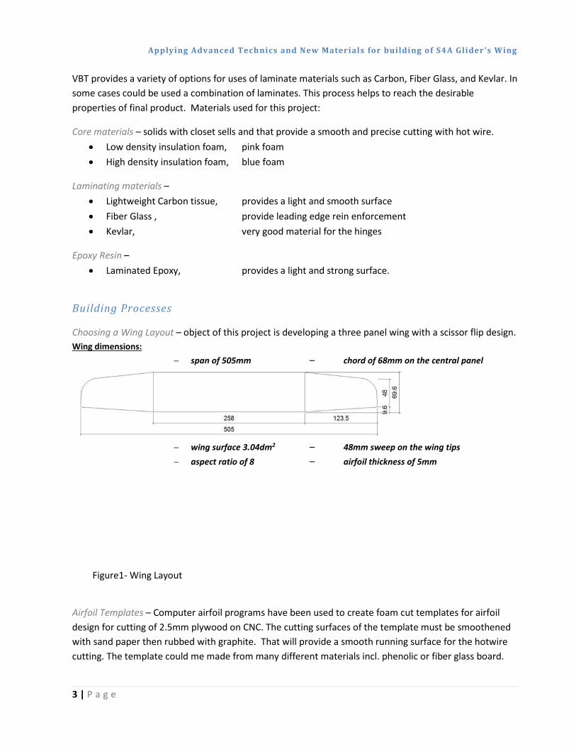
Choosing a Wing Layout – object of this project is developing a three panel wing with a scissor flip design. Wing dimensions:
− span of 505mm – chord of 68mm on the central panel
− wing surface 3.04dm2 – 48mm sweep on the wing tips − aspect ratio of 8 – airfoil thickness of 5mm
Figure1- Wing Layout
Airfoil Templates – Computer airfoil programs have been used to create foam cut templates for airfoil design for cutting of 2.5mm plywood on CNC. The cutting surfaces of the template must be smoothened with sand paper then rubbed with graphite. That will provide a smooth running surface for the hotwire cutting. The template could me made from many different materials incl. phenolic or fiber glass board.
Applying Advanced Technics and New Materials for building of S4A Glider’s Wing
4 | P a g e
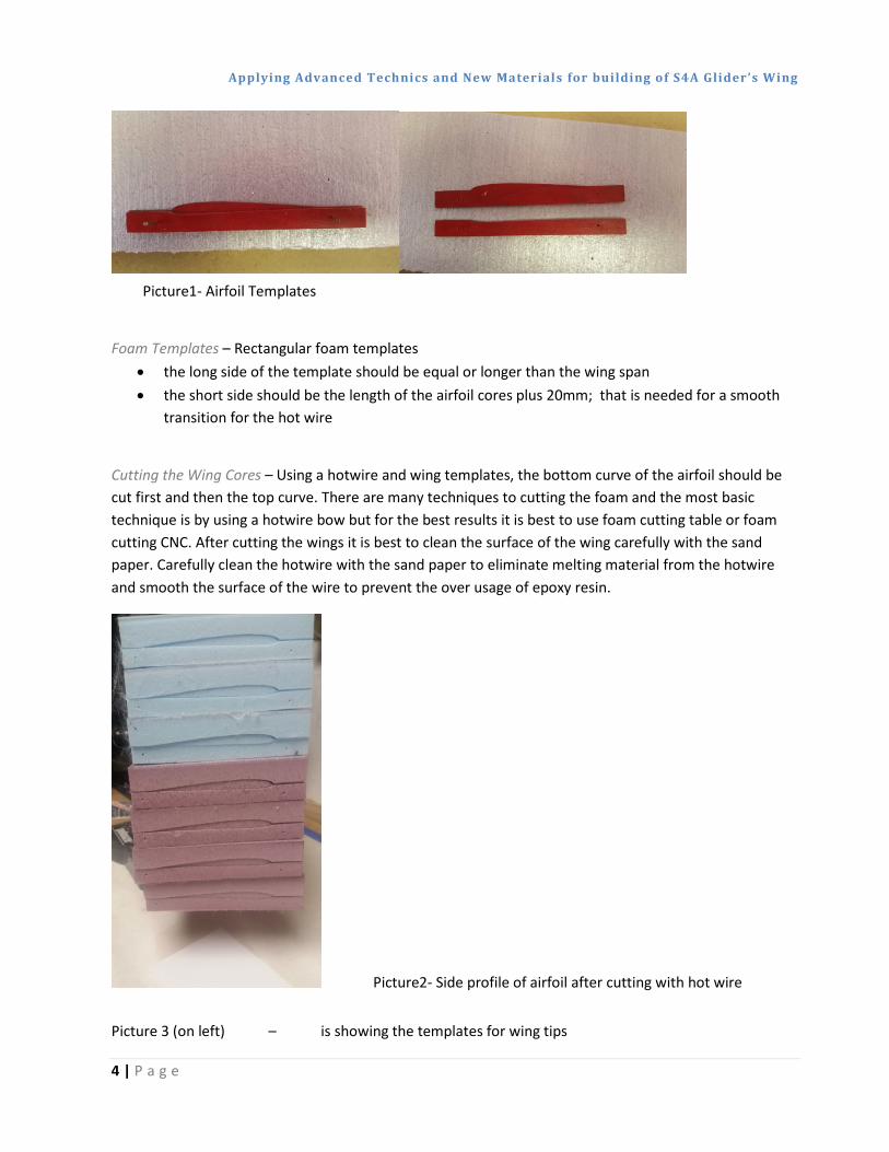
Picture1- Airfoil Templates
Foam Templates – Rectangular foam templates • the long side of the template should be equal or longer than the wing span • the short side should be the length of the airfoil cores plus 20mm; that is needed for a smooth
transition for the hot wire
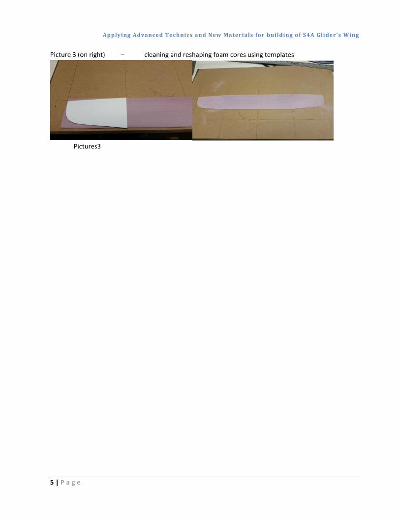
Cutting the Wing Cores – Using a hotwire and wing templates, the bottom curve of the airfoil should be cut first and then the top curve. There are many techniques to cutting the foam and the most basic technique is by using a hotwire bow but for the best results it is best to use foam cutting table or foam cutting CNC. After cutting the wings it is best to clean the surface of the wing carefully with the sand paper. Carefully clean the hotwire with the sand paper to eliminate melting material from the hotwire and smooth the surface of the wire to prevent the over usage of epoxy resin.
Picture2- Side profile of airfoil after cutting with hot wire
Picture 3 (on left) – is showing the templates for wing tips
Applying Advanced Technics and New Materials for building of S4A Glider’s Wing
5 | P a g e
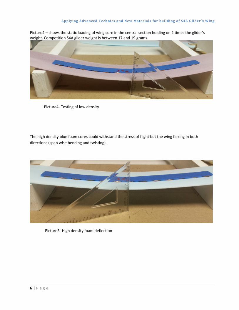
Picture 3 (on right) – cleaning and reshaping foam cores using templates
Pictures3
Applying Advanced Technics and New Materials for building of S4A Glider’s Wing
6 | P a g e
Picture4 – shows the static loading of wing core in the central section holding on 2 times the glider’s weight. Competition S4A glider weight is between 17 and 19 grams.
Picture4- Testing of low density
The high density blue foam cores could withstand the stress of flight but the wing flexing in both directions (span wise bending and twisting).
Picture5- High density foam deflection
Applying Advanced Technics and New Materials for building of S4A Glider’s Wing
7 | P a g e
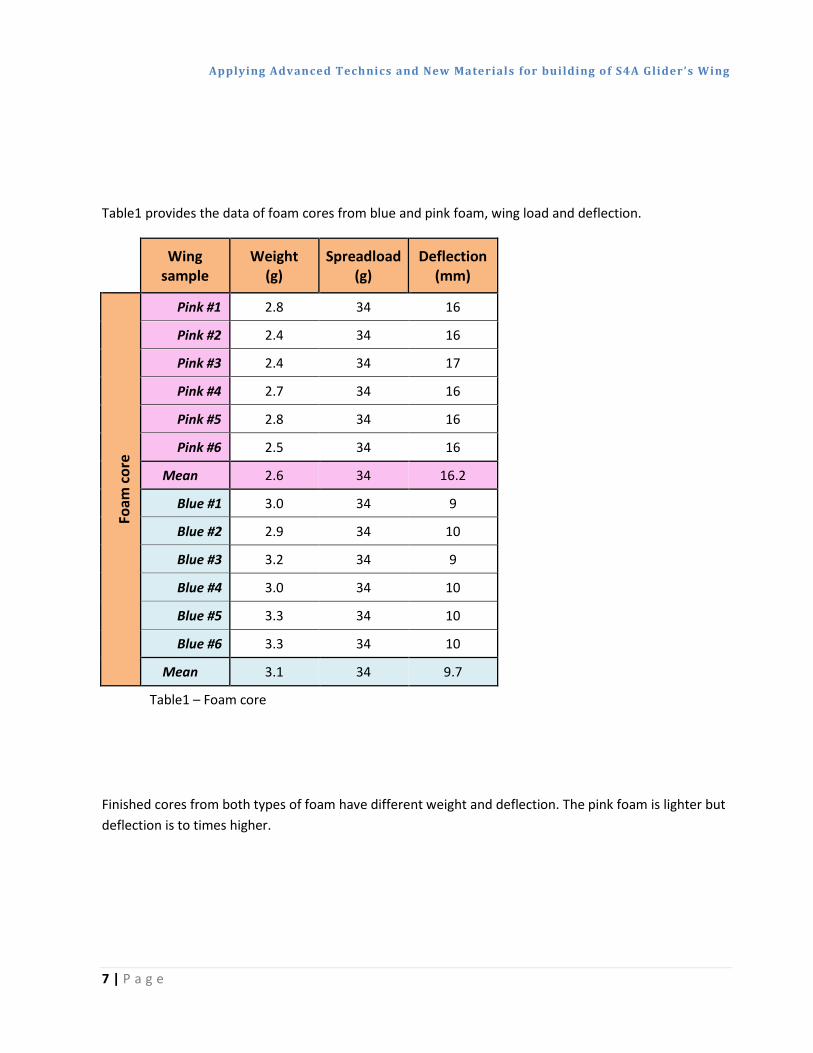
Table1 provides the data of foam cores from blue and pink foam, wing load and deflection.
Wing sample
Weight (g)
Spreadload (g)
Deflection (mm)
Foam
cor
e
Pink #1 2.8 34 16
Pink #2 2.4 34 16
Pink #3 2.4 34 17
Pink #4 2.7 34 16
Pink #5 2.8 34 16
Pink #6 2.5 34 16
Mean 2.6 34 16.2
Blue #1 3.0 34 9
Blue #2 2.9 34 10
Blue #3 3.2 34 9
Blue #4 3.0 34 10
Blue #5 3.3 34 10
Blue #6 3.3 34 10
Mean 3.1 34 9.7
Table1 – Foam core
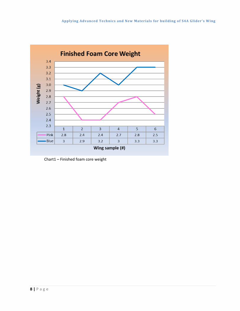
Finished cores from both types of foam have different weight and deflection. The pink foam is lighter but deflection is to times higher.
Applying Advanced Technics and New Materials for building of S4A Glider’s Wing
8 | P a g e
Chart1 – Finished foam core weight
Applying Advanced Technics and New Materials for building of S4A Glider’s Wing
9 | P a g e
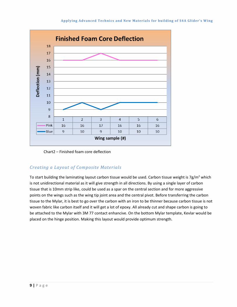
Chart2 – Finished foam core deflection
Creating a Layout of Composite Materials
To start building the laminating layout carbon tissue would be used. Carbon tissue weight is 7g/m2 which is not unidirectional material as it will give strength in all directions. By using a single layer of carbon tissue that is 10mm strip like, could be used as a spar on the central section and for more aggressive points on the wings such as the wing tip joint area and the central pivot. Before transferring the carbon tissue to the Mylar, it is best to go over the carbon with an iron to be thinner because carbon tissue is not woven fabric like carbon itself and it will get a lot of epoxy. All already cut and shape carbon is going to be attached to the Mylar with 3M 77 contact enhancive. On the bottom Mylar template, Kevlar would be placed on the hinge position. Making this layout would provide optimum strength.
Applying Advanced Technics and New Materials for building of S4A Glider’s Wing
10 | P a g e
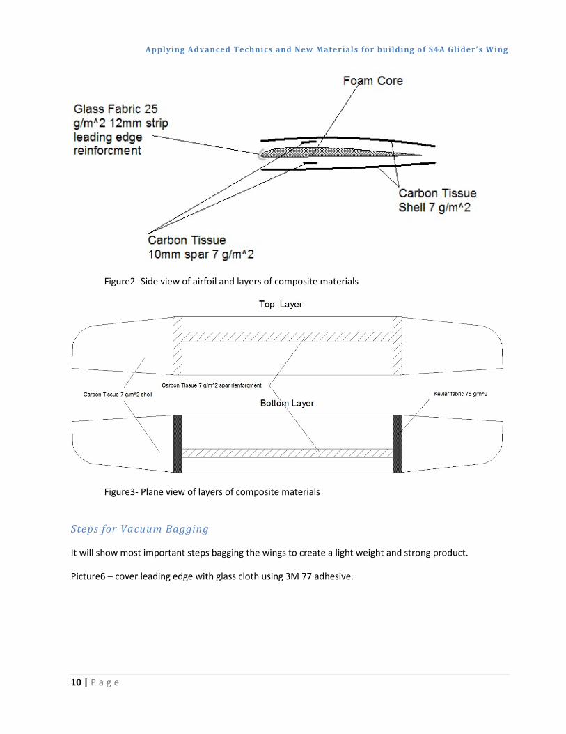
Figure2- Side view of airfoil and layers of composite materials
Figure3- Plane view of layers of composite materials
Steps for Vacuum Bagging
It will show most important steps bagging the wings to create a light weight and strong product.
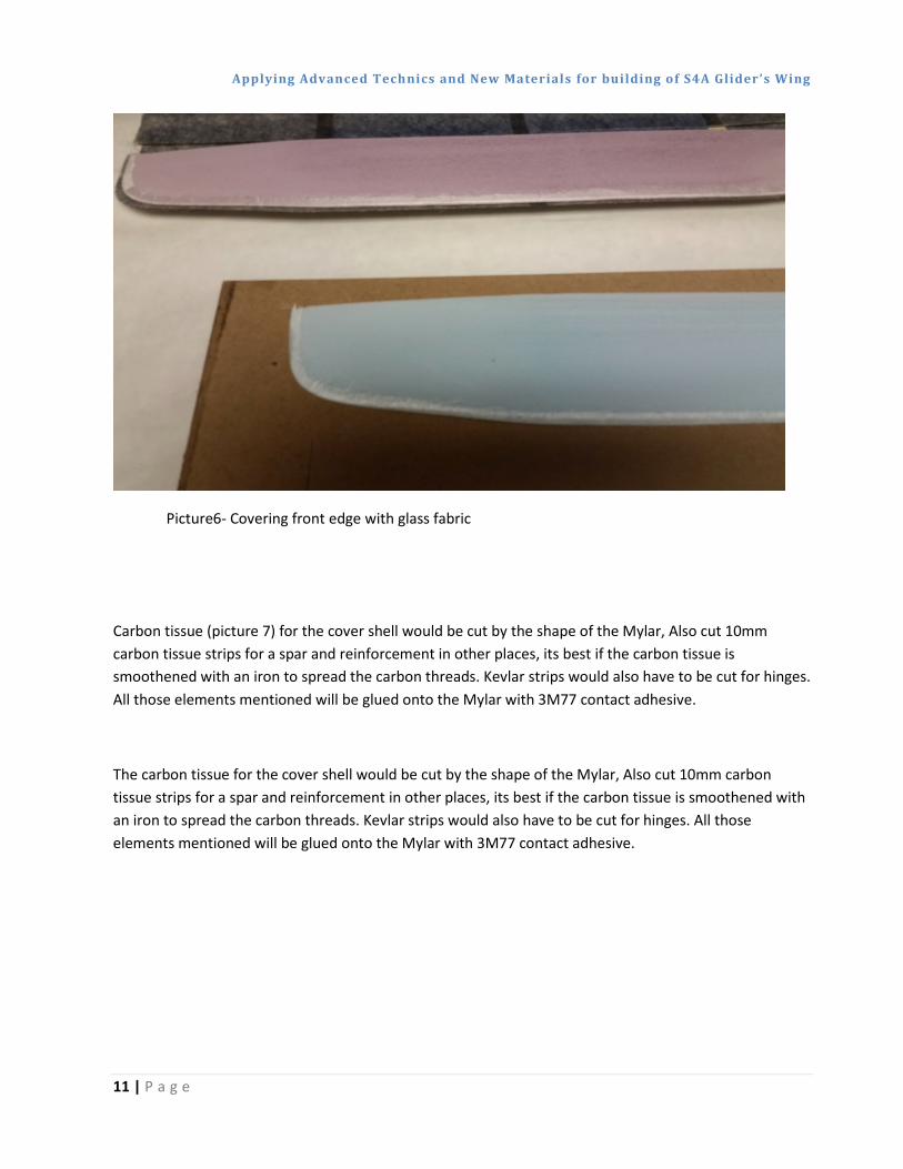
Picture6 – cover leading edge with glass cloth using 3M 77 adhesive.
Applying Advanced Technics and New Materials for building of S4A Glider’s Wing
11 | P a g e
Picture6- Covering front edge with glass fabric
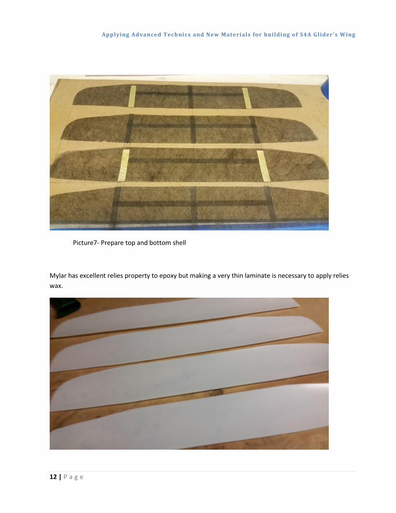
Carbon tissue (picture 7) for the cover shell would be cut by the shape of the Mylar, Also cut 10mm carbon tissue strips for a spar and reinforcement in other places, its best if the carbon tissue is smoothened with an iron to spread the carbon threads. Kevlar strips would also have to be cut for hinges. All those elements mentioned will be glued onto the Mylar with 3M77 contact adhesive.
The carbon tissue for the cover shell would be cut by the shape of the Mylar, Also cut 10mm carbon tissue strips for a spar and reinforcement in other places, its best if the carbon tissue is smoothened with an iron to spread the carbon threads. Kevlar strips would also have to be cut for hinges. All those elements mentioned will be glued onto the Mylar with 3M77 contact adhesive.
Applying Advanced Technics and New Materials for building of S4A Glider’s Wing
12 | P a g e
Picture7- Prepare top and bottom shell
Mylar has excellent relies property to epoxy but making a very thin laminate is necessary to apply relies wax.
Applying Advanced Technics and New Materials for building of S4A Glider’s Wing
13 | P a g e
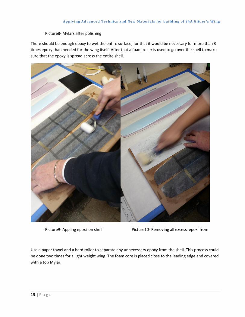
Picture8- Mylars after polishing
There should be enough epoxy to wet the entire surface, for that it would be necessary for more than 3 times epoxy than needed for the wing itself. After that a foam roller is used to go over the shell to make sure that the epoxy is spread across the entire shell.
Picture9- Appling epoxi on shell Picture10- Removing all excess epoxi from
Use a paper towel and a hard roller to separate any unnecessary epoxy from the shell. This process could be done two times for a light weight wing. The foam core is placed close to the leading edge and covered with a top Mylar.
Applying Advanced Technics and New Materials for building of S4A Glider’s Wing
14 | P a g e
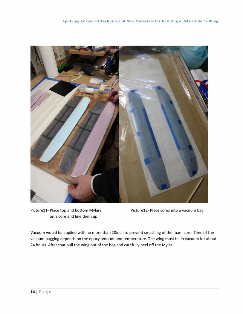
Picture11- Place top and bottom Mylars Picture12- Place cores into a vacuum bag on a core and line them up
Vacuum would be applied with no more than 20inch to prevent smashing of the foam core. Time of the vacuum bagging depends on the epoxy amount and temperature. The wing must be in vacuum for about 24 hours. After that pull the wing out of the bag and carefully peel off the Mylar.
Applying Advanced Technics and New Materials for building of S4A Glider’s Wing
15 | P a g e
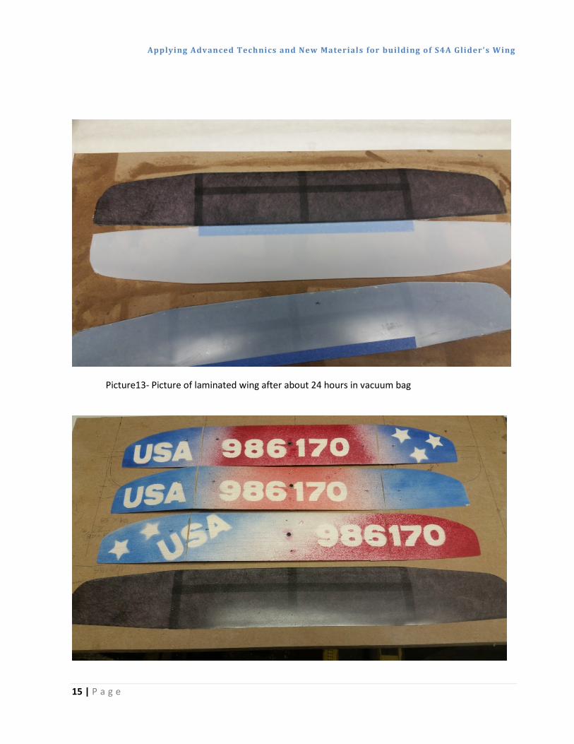
Picture13- Picture of laminated wing after about 24 hours in vacuum bag
Applying Advanced Technics and New Materials for building of S4A Glider’s Wing
16 | P a g e
Picture14- Different design and size of laminated wings
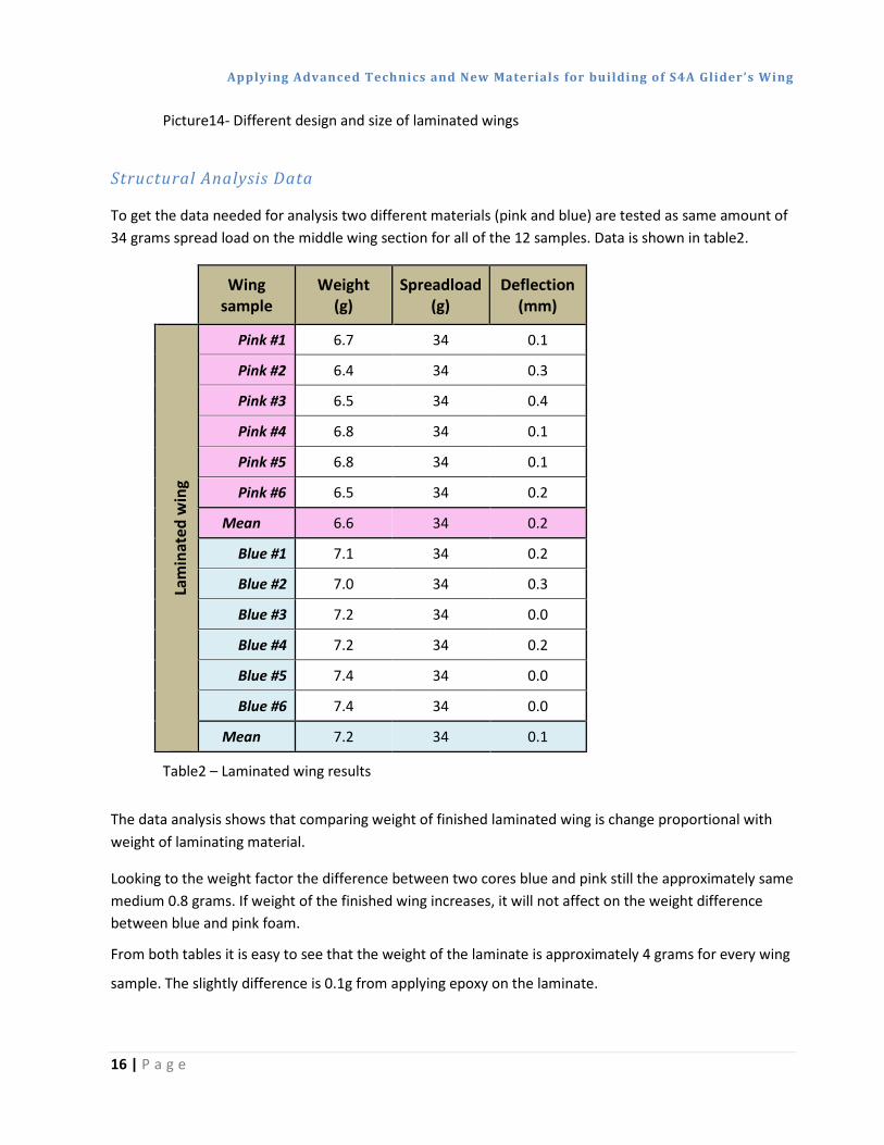
Structural Analysis Data
To get the data needed for analysis two different materials (pink and blue) are tested as same amount of 34 grams spread load on the middle wing section for all of the 12 samples. Data is shown in table2.
Wing
sample Weight
(g) Spreadload
(g) Deflection
(mm)
Lam
inat
ed w
ing
Pink #1 6.7 34 0.1
Pink #2 6.4 34 0.3
Pink #3 6.5 34 0.4
Pink #4 6.8 34 0.1
Pink #5 6.8 34 0.1
Pink #6 6.5 34 0.2
Mean 6.6 34 0.2
Blue #1 7.1 34 0.2
Blue #2 7.0 34 0.3
Blue #3 7.2 34 0.0
Blue #4 7.2 34 0.2
Blue #5 7.4 34 0.0
Blue #6 7.4 34 0.0
Mean 7.2 34 0.1
Table2 – Laminated wing results
The data analysis shows that comparing weight of finished laminated wing is change proportional with weight of laminating material.
Looking to the weight factor the difference between two cores blue and pink still the approximately same medium 0.8 grams. If weight of the finished wing increases, it will not affect on the weight difference between blue and pink foam.
From both tables it is easy to see that the weight of the laminate is approximately 4 grams for every wing
sample. The slightly difference is 0.1g from applying epoxy on the laminate.

Applying Advanced Technics and New Materials for building of S4A Glider’s Wing
17 | P a g e
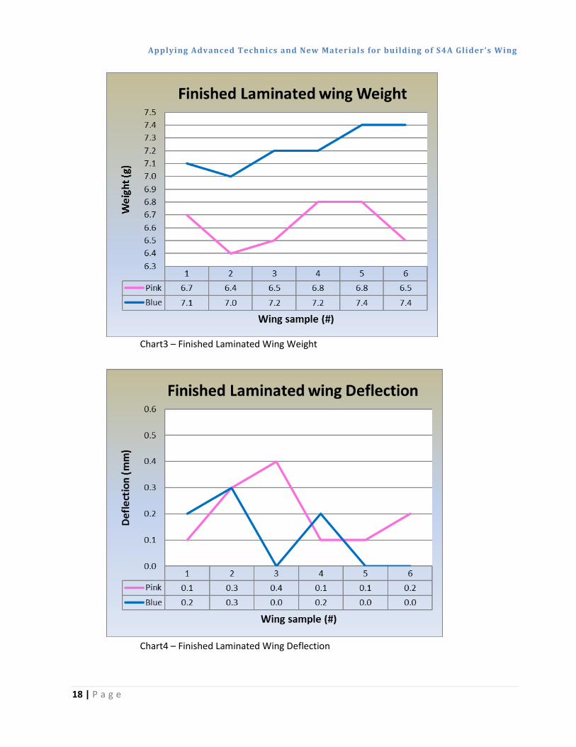
The wing stiffness is increased significantly. Results are showing that both wing cores materials laminating in same way have very close or equal numbers. As for deflection, the laminated wing deflection is 0.2 mm for pink and 0.1 mm for blue foam.
Applying Advanced Technics and New Materials for building of S4A Glider’s Wing
18 | P a g e
Chart3 – Finished Laminated Wing Weight
Chart4 – Finished Laminated Wing Deflection
Applying Advanced Technics and New Materials for building of S4A Glider’s Wing
19 | P a g e
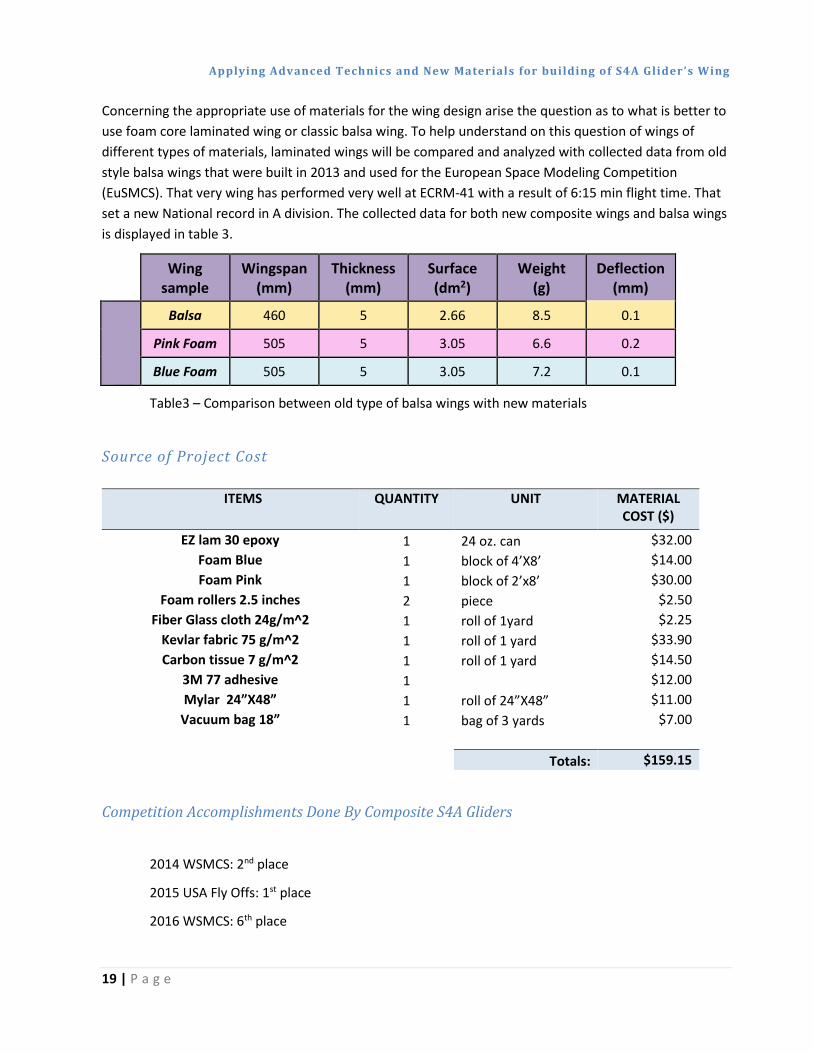
Concerning the appropriate use of materials for the wing design arise the question as to what is better to use foam core laminated wing or classic balsa wing. To help understand on this question of wings of different types of materials, laminated wings will be compared and analyzed with collected data from old style balsa wings that were built in 2013 and used for the European Space Modeling Competition (EuSMCS). That very wing has performed very well at ECRM-41 with a result of 6:15 min flight time. That set a new National record in A division. The collected data for both new composite wings and balsa wings is displayed in table 3.
Wing
sample Wingspan
(mm) Thickness
(mm) Surface (dm2)
Weight (g)
Deflection (mm)
Balsa 460 5 2.66 8.5 0.1
Pink Foam 505 5 3.05 6.6 0.2
Blue Foam 505 5 3.05 7.2 0.1
Table3 – Comparison between old type of balsa wings with new materials
Source of Project Cost
ITEMS QUANTITY UNIT MATERIAL COST ($)
EZ lam 30 epoxy 1 24 oz. can $32.00 Foam Blue 1 block of 4’X8’ $14.00 Foam Pink 1 block of 2’x8’ $30.00
Foam rollers 2.5 inches 2 piece $2.50 Fiber Glass cloth 24g/m^2 1 roll of 1yard $2.25
Kevlar fabric 75 g/m^2 1 roll of 1 yard $33.90 Carbon tissue 7 g/m^2 1 roll of 1 yard $14.50
3M 77 adhesive 1
$12.00 Mylar 24”X48” 1 roll of 24”X48” $11.00
Vacuum bag 18” 1 bag of 3 yards $7.00
Totals: $159.15
Competition Accomplishments Done By Composite S4A Gliders
2014 WSMCS: 2nd place
2015 USA Fly Offs: 1st place
2016 WSMCS: 6th place
Applying Advanced Technics and New Materials for building of S4A Glider’s Wing
20 | P a g e
Conclusions and Recommendations
Based on the experience of developing the laminated wing, testing and performing in competitions from past years could state that the wing has never suffered a flaw. For this time period there has been produced over 22 laminated wings with more than 20 flights on most of them.
The use of laminated wing is more reliable for S4A gliders since it has a more precise airfoil, lighter weight, and an option for a larger wing surface area if chosen to.


