Download - APX 320/530/740 - Operating instructions

Operating InstructionsAPX 320/530/740
1APX 320/530/740
Operating Instructions
ForewordWe are pleased to welcome you as a new Sophos APX Series customer.
Sophos APX Series access points are high performance wireless products using
the latest 802.11ac Wave 2 technology for a best-in-class user experience. The
APX Series models can be easily managed in Sophos Central, our cloud-based
security management platform. All you need to do is set up a Sophos Central
account and plug in the device anywhere in your network. The access point
will find the cloud-based controller automatically and become operable within
seconds. Management of these APX Series models in Sophos XG Firewall will be
available in a maintenance release of version 17.5.
These operating instructions will help you setup your Sophos Central account,
install and configure your Sophos APX Series access point and also provide
detailed technical specifications. In addition, please also see the following
documents that contain useful information on safety, regulatory compliance, and
configuration options:
Ì Sophos APX Series Safety Instructions and Regulatory Information
Ì Sophos APX Series Quick Start Guide
The instructions must be read carefully prior to using the device and should
be kept in a safe place. You can download all user manuals and additional
documentation from the Sophos Knowledgebase under
www.sophos.com/en-us/support/knowledgebase.aspx or from
www.sophos.com/get-started-ap.
Security SymbolsThe following symbol and its meaning appears in the Quick Start Guide, Safety
Instructions and in these Operating Instructions.
Caution and Important Note. If these notes are not correctly observed:
Ì This is dangerous to life and the environment
Ì The access point may be damaged
Ì The functions of the access point will be no longer guaranteed
Ì Sophos shall not be liable for damages arising from a
failure to comply with the Safety Instructions
Designed UseThe access point must be installed pursuant to the current installation notes.
Otherwise failure-free and safe operation cannot be guaranteed. The EU
declaration of conformity is available upon request from the following address:
Sophos Technology GmbH Amalienbadstr. 41/Bau 52 76227 Karlsruhe Germany
2APX 320/530/740
Operating Instructions
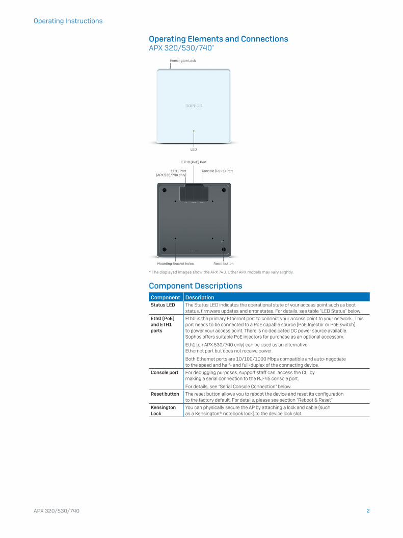
Operating Elements and ConnectionsAPX 320/530/740*
LED
Kensington Lock
ETH1 Port (APX 530/740 only)
ETH0 (PoE) Port
Console (RJ45) Port
Reset buttonMounting Bracket holes
* The displayed images show the APX 740. Other APX models may vary slightly.
Component DescriptionsComponent DescriptionStatus LED The Status LED indicates the operational state of your access point such as boot
status, firmware updates and error states. For details, see table “LED Status” below.
Eth0 (PoE) and ETH1 ports
Eth0 is the primary Ethernet port to connect your access point to your network. This port needs to be connected to a PoE capable source (PoE Injector or PoE switch) to power your access point. There is no dedicated DC power source available. Sophos offers suitable PoE injectors for purchase as an optional accessory.
Eth1 (on APX 530/740 only) can be used as an alternative Ethernet port but does not receive power.
Both Ethernet ports are 10/100/1000 Mbps compatible and auto-negotiate to the speed and half- and full-duplex of the connecting device.
Console port For debugging purposes, support staff can access the CLI by making a serial connection to the RJ-45 console port.
For details, see “Serial Console Connection” below.
Reset button The reset button allows you to reboot the device and reset its configuration to the factory default. For details, please see section “Reboot & Reset”
Kensington Lock
You can physically secure the AP by attaching a lock and cable (such as a Kensington® notebook lock) to the device lock slot.
3APX 320/530/740
Operating Instructions
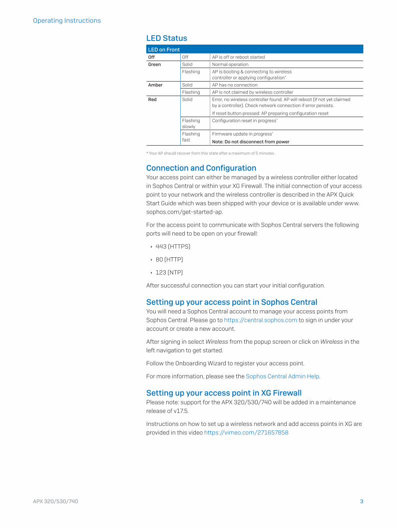
LED StatusLED on FrontOff Off AP is off or reboot started
Green Solid Normal operation
Flashing AP is booting & connecting to wireless controller or applying configuration*
Amber Solid AP has no connection
Flashing AP is not claimed by wireless controller
Red Solid Error, no wireless controller found. AP will reboot (if not yet claimed by a controller). Check network connection if error persists.
If reset button pressed: AP preparing configuration reset
Flashing slowly
Configuration reset in progress*
Flashing fast
Firmware update in progress*
Note: Do not disconnect from power
* Your AP should recover from this state after a maximum of 5 minutes.
Connection and ConfigurationYour access point can either be managed by a wireless controller either located
in Sophos Central or within your XG Firewall. The initial connection of your access
point to your network and the wireless controller is described in the APX Quick
Start Guide which was been shipped with your device or is available under www.
sophos.com/get-started-ap.
For the access point to communicate with Sophos Central servers the following
ports will need to be open on your firewall:
Ì 443 (HTTPS)
Ì 80 (HTTP)
Ì 123 (NTP)
After successful connection you can start your initial configuration.
Setting up your access point in Sophos CentralYou will need a Sophos Central account to manage your access points from
Sophos Central. Please go to https://central.sophos.com to sign in under your
account or create a new account.
After signing in select Wireless from the popup screen or click on Wireless in the
left navigation to get started.
Follow the Onboarding Wizard to register your access point.
For more information, please see the Sophos Central Admin Help.
Setting up your access point in XG FirewallPlease note: support for the APX 320/530/740 will be added in a maintenance
release of v17.5.
Instructions on how to set up a wireless network and add access points in XG are
provided in this video https://vimeo.com/271657858

4APX 320/530/740
Operating Instructions
Reboot & ResetYour access point can be rebooted with the installed configuration or reset to the
factory default configuration depending on how long you press and hold the reset
button.
Reboot with current image and configuration1. Press reset button
2. Release reset button
3. AP reboots (LED will go off, then will turn to solid green)
Reboot with current image and clear configuration1. Press and hold reset button
2. AP reboots (LED will go off and then switch to green briefly)
3. LED will turn solid red for 5 sec. You can still cancel
the configuration clearance process by releasing the
reset button before the LED starts blinking
4. LED will blink red (configuration will be cleared)
5. Release reset button
6. AP reboots with factory default settings
Reset Button
Status LED
Released
Pressed
Solid Solid Blinking
Reboot Reboot clear config
5 Sec
Off

5APX 320/530/740
Operating Instructions
Technical specificationsAPX 320Environment
Power consumption 11.5 W (max.)
Power over Ethernet (PoE) requirements
802.3af
Operating temperature 0°-40° C
Storage temperature -40°-70° C
Humidity 10-95% non-condensing
Hazardous substances RoHS-2 and REACH compliant
Physical specification
I/O ports 1x RJ45 connector console serial port
1x RJ45 10/100/1000 Ethernet w/PoE (802.3af)
1x Reset button
1x Kensington security slot
Memory 512 MByte DDR3L
512 Mbyte NAND Flash
4 Mbyte SPI NOR Flash
Mounting Desktop
Wall-mount hang
Ceiling (15/16, 9/16, 3/8 inch ceiling tracks)
Dimensions (Width x Depth x Height)
155x155x38 mm
Weight 0,474 kg
Wireless specification
Radios 1x 2.4 GHz/5 GHz dual-band
1x 5 GHz single band
1x Bluetooth low energy (BLE)
Antennas 2x internal dual band antenna for Radio-1 (omni-directional)
2x internal 5 GHz antenna for Radio-2 (omni-directional)
1x internal 2.4 GHz antenna for BLE
Antenna Peak Gain 3.7 dBi at 2.4 GHz, 6.7 dBi at 5 GHz
MIMO capabilities 2x2:2
Supported WLAN standards IEEE 802.11 a/b/g/n/ac Wave 2
SSIDs 8 per radio, 16 in total
Max. Throughput 867 Mbps (5G) + 867 Mbps (5G)
APX 320Band/Mode Data Rate TX Power
Maximum EIRP (dBm)
RX Sensitivity(dBm)
2.412-2.472 GHz (11b)
1 Mbps 23 -99
2 Mbps 23 -96
5.5 Mbps 23 -94
11 Mbps 23 -91
2.412-2.472 GHz (11g)
6 Mbps 23 -94
9 Mbps 23 -92
12 Mbps 22 -91
18 Mbps 22 -89
24 Mbps 21 -86
36 Mbps 21 -82
48 Mbps 19 -78
54 Mbps 19 -76

6APX 320/530/740
Operating Instructions
APX 3202.412-2.472 GHz (11n HT20)
MCS 0 23 -93
MCS 1 23 -90
MCS 2 22 -88
MCS 3 22 -85
MCS 4 21 -82
MCS 5 21 -78
MCS 6 19 -76
MCS 7 19 -75
MCS 8 18 -71
5.180-5.825 GHz (11a)
6 Mbps 22 -91
9 Mbps 22 -90
12 Mbps 21 -90
18 Mbps 21 -88
24 Mbps 20 -85
36 Mbps 20 -82
48 Mbps 18 -77
54 Mbps 18 -76
5.180-5.825 GHz (11ac VHT20)
MCS0 22 -91
MCS1 22 -89
MCS2 21 -87
MCS3 21 -85
MCS4 20 -82
MCS5 20 -78
MCS6 18 -76
MCS7 18 -74
MCS8 17 -70
5.180-5.825 GHz (11ac VHT40)
MCS0 22 -89
MCS1 22 -86
MCS2 21 -85
MCS3 21 -82
MCS4 20 -79
MCS5 20 -75
MCS6 18 -73
MCS7 18 -72
MCS8 17 -68
MCS9 17 -66
5.180-5.825 GHz (11ac VHT80)
MCS0 22 -87
MCS1 22 -84
MCS2 21 -82
MCS3 21 -79
MCS4 20 -76
MCS5 20 -72
MCS6 18 -70
MCS7 18 -69
MCS8 15 -65
MCS9 14 -63
7APX 320/530/740
Operating Instructions
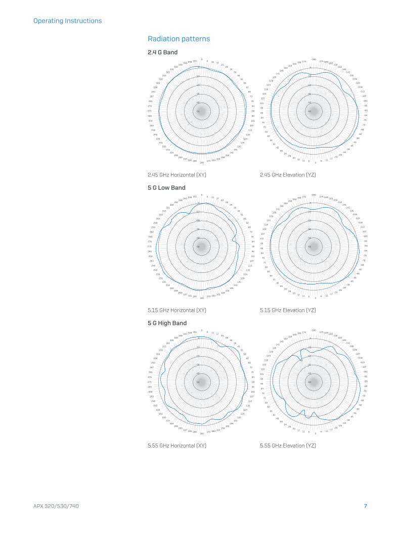
Radiation patterns
2.4 G Band
-50
-40
-30
-20
-10
0
06 11 17
2328
3439
45
51
56
62
68
73
79
84
90
96
101
107
113
118
124
129
135
141146
152158
163169174180
186191197203
208214
219
225
231
236
242
248
253
259
265
270
276
281
287
293
298
304
310
315
321326
332338
343 349 355
56
62
68
73
79
84
90
96
101
107
113
118
124
129
135
141146
152158
163169 174
-180-174-169-163
-158-152
-146-141
-135
-129
-124
-118
-113
-107
-101
-96
-90
-84
-79
-73
-68
-62
-56
-51
-45
-39-34
-28-23
-17-11-6
061117
2328
3439
45
51
-50
-40
-30
-20
-10
0
2.45 GHz Horizontal (XY) 2.45 GHz Elevation (YZ)
5 G Low Band
-50
-40
-30
-20
-10
0
06 11 17
2328
3439
45
51
56
62
68
73
79
84
90
96
101
107
113
118
124
129
135
141146
152158
163169174180
186191197203
208214
219
225
231
236
242
248
253
259
265
270
276
281
287
293
298
304
310
315
321326
332338
343 349 355
56
62
68
73
79
84
90
96
101
107
113
118
124
129
135
141146
152158
163169 174
-180-174-169-163
-158-152
-146-141
-135
-129
-124
-118
-113
-107
-101
-96
-90
-84
-79
-73
-68
-62
-56
-51
-45
-39-34
-28-23
-17-11-6
061117
2328
3439
45
51
-50
-40
-30
-20
-10
0
5.15 GHz Horizontal (XY) 5.15 GHz Elevation (YZ)
5 G High Band
-50
-40
-30
-20
-10
0
06 11 17
2328
3439
45
51
56
62
68
73
79
84
90
96
101
107
113
118
124
129
135
141146
152158
163169174180
186191197203
208214
219
225
231
236
242
248
253
259
265
270
276
281
287
293
298
304
310
315
321326
332338
343 349 355
56
62
68
73
79
84
90
96
101
107
113
118
124
129
135
141146
152158
163169 174
-180-174-169-163
-158-152
-146-141
-135
-129
-124
-118
-113
-107
-101
-96
-90
-84
-79
-73
-68
-62
-56
-51
-45
-39-34
-28-23
-17-11-6
061117
2328
3439
45
51
-50
-40
-30
-20
-10
0
5.55 GHz Horizontal (XY) 5.55 GHz Elevation (YZ)

8APX 320/530/740
Operating Instructions
APX 530Environment
Power consumption 16.7 W (max.)
Power over Ethernet (PoE) requirements
802.3at
Operating temperature 0°-40° C
Storage temperature -40°-70° C
Humidity 10-95% non-condensing
Hazardous substances RoHS-2 and REACH compliant
Physical specification
I/O ports 1x RJ45 connector console serial port
1x RJ45 10/100/1000 Ethernet port
1x RJ45 10/100/1000 Ethernet w/PoE (802.3at)
1x Reset button
1x Kensington security slot
Memory 1 Gbyte DDR3L
512 Mbyte NAND Flash
4 Mbyte SPI NOR Flash
Mounting Desktop
Wall-mount hang
Ceiling (15/16, 9/16, 3/8 inch ceiling tracks)
Dimensions (Width x Depth x Height)
183x183x39 mm
Weight 0,922 kg
Wireless specification
Radios 1x 2.4 GHz single band
1x 5 GHz single band
1x Bluetooth low energy (BLE)
Antennas 3x internal 2.4 GHz antenna for Radio-1 (omni-directional)
3x internal 5 GHz antenna for Radio-2 (omni-directional)
1x internal 2.4 GHz antenna for BLE
Antenna Peak Gain 4.7 dBi at 2.4 GHz, 5.9 dBi at 5 GHz
MIMO capabilities 3x3:3
Supported WLAN standards IEEE 802.11 a/b/g/n/ac Wave 2
SSIDs 8 per radio, 16 in total
Max. Throughput 1300 Mbps (5G) + 450 Mbps (2.4G)
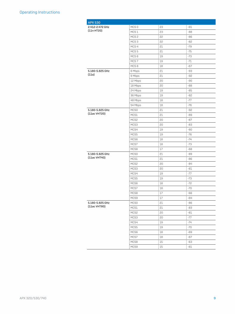
APX 530Band/Mode Data Rate TX Power
Maximum EIRP (dBm)
RX Sensitivity(dBm)
2.412-2.472 GHz (11b)
1 Mbps 24 -97
2 Mbps 24 -94
5.5 Mbps 24 -92
11 Mbps 24 -89
2.412-2.472 GHz (11g)
6 Mbps 23 -92
9 Mbps 23 -90
12 Mbps 23 -89
18 Mbps 23 -87
24 Mbps 22 -84
36 Mbps 22 -81
48 Mbps 20 -76
54 Mbps 20 -75
9APX 320/530/740
Operating Instructions
APX 5302.412-2.472 GHz (11n HT20)
MCS 0 23 -91
MCS 1 23 -88
MCS 2 22 -86
MCS 3 22 -82
MCS 4 21 -79
MCS 5 21 -75
MCS 6 19 -73
MCS 7 19 -71
MCS 8 18 -67
5.180-5.825 GHz (11a)
6 Mbps 21 -93
9 Mbps 21 -92
12 Mbps 20 -90
18 Mbps 20 -88
24 Mbps 19 -85
36 Mbps 19 -82
48 Mbps 18 -77
54 Mbps 18 -76
5.180-5.825 GHz (11ac VHT20)
MCS0 21 -92
MCS1 21 -89
MCS2 20 -87
MCS3 20 -83
MCS4 19 -80
MCS5 19 -76
MCS6 18 -74
MCS7 18 -73
MCS8 17 -68
5.180-5.825 GHz (11ac VHT40)
MCS0 21 -89
MCS1 21 -86
MCS2 20 -84
MCS3 20 -81
MCS4 19 -77
MCS5 19 -73
MCS6 18 -72
MCS7 18 -70
MCS8 17 -66
MCS9 17 -64
5.180-5.825 GHz (11ac VHT80)
MCS0 21 -86
MCS1 21 -83
MCS2 20 -81
MCS3 20 -77
MCS4 19 -74
MCS5 19 -70
MCS6 18 -69
MCS7 18 -67
MCS8 15 -63
MCS9 15 -61

10APX 320/530/740
Operating Instructions
Radiation patterns
2.4 G Band
-50
-40
-30
-20
-10
0
06 11 17
2328
3439
45
51
56
62
68
73
79
84
90
96
101
107
113
118
124
129
135
141146
152158
163169174180
186191197203
208214
219
225
231
236
242
248
253
259
265
270
276
281
287
293
298
304
310
315
321326
332338
343 349 355
56
62
68
73
79
84
90
96
101
107
113
118
124
129
135
141146
152158
163169 174
-180-174-169-163
-158-152
-146-141
-135
-129
-124
-118
-113
-107
-101
-96
-90
-84
-79
-73
-68
-62
-56
-51
-45
-39-34
-28-23
-17-11-6
061117
2328
3439
45
51
-50
-40
-30
-20
-10
0
2.45 GHz Horizontal (XY) 2.45 GHz Elevation (YZ)
5 G Band
-50
-40
-30
-20
-10
0
06 11 17
2328
3439
45
51
56
62
68
73
79
84
90
96
101
107
113
118
124
129
135
141146
152158
163169174180
186191197203
208214
219
225
231
236
242
248
253
259
265
270
276
281
287
293
298
304
310
315
321326
332338
343 349 355
56
62
68
73
79
84
90
96
101
107
113
118
124
129
135
141146
152158
163169 174
-180-174-169-163
-158-152
-146-141
-135
-129
-124
-118
-113
-107
-101
-96
-90
-84
-79
-73
-68
-62
-56
-51
-45
-39-34
-28-23
-17-11-6
061117
2328
3439
45
51
-50
-40
-30
-20
-10
0
5.55 GHz Horizontal (XY) 5.55 GHz Elevation (YZ)

11APX 320/530/740
Operating Instructions
Technical specificationsAPX 740Environment
Power consumption 22.4 W
Power over Ethernet (PoE) requirements
802.3at
Operating temperature 0°-40° C
Storage temperature -40°-70° C
Humidity 10-95% non-condensing
Hazardous substances RoHS-2 and REACH compliant
Physical specification
I/O ports 1x RJ45 connector console serial port
1x RJ45 10/100/1000 Ethernet port
1x RJ45 10/100/1000 Ethernet w/PoE (802.3at)
1x Reset button
1x Kensington security slot
Memory 1 Gbyte DDR3L
512 Mbyte NAND Flash
4 Mbyte SPI NOR Flash
Mounting Desktop
Wall-mount hang
Ceiling (15/16, 9/16, 3/8 inch ceiling tracks)
Dimensions (Width x Depth x Height)
195x195x43 mm
Weight 1.012 kg
Wireless specification
Radios 1x 2.4 GHz single band
1x 5 GHz single band
1x Bluetooth low energy (BLE)
Antennas 4x internal 2.4 GHz antenna for Radio-1 (omni-directional)
4x internal 5 GHz antenna for Radio-2 (omni-directional)
1x internal 2.4 GHz antenna for BLE
Antenna Peak Gain 4.1 dBi at 2.4 GHz, 5.7 dBi at 5 GHz
MIMO capabilities 4x4:4
Supported WLAN standards IEEE 802.11 a/b/g/n/ac Wave 2
SSIDs 8 per radio, 16 in total
Max. Throughput 1733 Mbps (5G) + 600 Mbps (2.4G)
APX 740Band/Mode Data Rate TX Power
Maximum EIRP (dBm)
RX Sensitivity(dBm)
2.412-2.472 GHz (11b)
1 Mbps 24 -99
2 Mbps 24 -96
5.5 Mbps 24 -94
11 Mbps 24 -91
2.412-2.472 GHz (11g)
6 Mbps 23 -94
9 Mbps 23 -93
12 Mbps 22 -92
18 Mbps 22 -90
24 Mbps 21 -86
36 Mbps 21 -83
48 Mbps 20 -79
54 Mbps 20 -77

12APX 320/530/740
Operating Instructions
APX 7402.412-2.472 GHz (11n HT20)
MCS 0 23 -94
MCS 1 23 -90
MCS 2 22 -88
MCS 3 22 -84
MCS 4 21 -81
MCS 5 21 -77
MCS 6 19 -75
MCS 7 19 -74
MCS 8 18 -70
5.180-5.825 GHz (11a)
6 Mbps 22 -92
9 Mbps 22 -91
12 Mbps 21 -89
18 Mbps 21 -87
24 Mbps 20 -84
36 Mbps 20 -81
48 Mbps 19 -76
54 Mbps 19 -74
5.180-5.825 GHz (11ac VHT20)
MCS0 22 -92
MCS1 22 -88
MCS2 22 -86
MCS3 22 -82
MCS4 20 -79
MCS5 20 -74
MCS6 18 -73
MCS7 18 -72
MCS8 17 -67
5.180-5.825 GHz (11ac VHT40)
MCS0 22 -89
MCS1 22 -85
MCS2 22 -83
MCS3 22 -79
MCS4 20 -76
MCS5 20 -72
MCS6 18 -71
MCS7 18 -69
MCS8 17 -65
MCS9 17 -63
5.180-5.825 GHz (11ac VHT80)
MCS0 22 -86
MCS1 22 -82
MCS2 22 -80
MCS3 22 -76
MCS4 20 -73
MCS5 20 -69
MCS6 18 -67
MCS7 18 -66
MCS8 15 -62
MCS9 15 -60

13APX 320/530/740
Operating Instructions
Radiation patterns
2.4 G Band
-50
-40
-30
-20
-10
0
06 11 17
2328
3439
45
51
56
62
68
73
79
84
90
96
101
107
113
118
124
129
135
141146
152158
163169174180
186191197203
208214
219
225
231
236
242
248
253
259
265
270
276
281
287
293
298
304
310
315
321326
332338
343 349 355
56
62
68
73
79
84
90
96
101
107
113
118
124
129
135
141146
152158
163169 174
-180-174-169-163
-158-152
-146-141
-135
-129
-124
-118
-113
-107
-101
-96
-90
-84
-79
-73
-68
-62
-56
-51
-45
-39-34
-28-23
-17-11-6
061117
2328
3439
45
51
-50
-40
-30
-20
-10
0
2.45 GHz Horizontal (XY) 2.45 GHz Elevation (YZ)
5G Band
-50
-40
-30
-20
-10
0
06 11 17
2328
3439
45
51
56
62
68
73
79
84
90
96
101
107
113
118
124
129
135
141146
152158
163169174180
186191197203
208214
219
225
231
236
242
248
253
259
265
270
276
281
287
293
298
304
310
315
321326
332338
343 349 355
56
62
68
73
79
84
90
96
101
107
113
118
124
129
135
141146
152158
163169 174
-180-174-169-163
-158-152
-146-141
-135
-129
-124
-118
-113
-107
-101
-96
-90
-84
-79
-73
-68
-62
-56
-51
-45
-39-34
-28-23
-17-11-6
061117
2328
3439
45
51
-50
-40
-30
-20
-10
0
5.55 GHz Horizontal (XY) 5.55 GHz Elevation (YZ)

14APX 320/530/740
Operating Instructions
Mounting instructionsThere are various mounting options available allowing you to hang your access
point on the wall or mount it to various ceiling types. The following sections
provide detailed instructions for the various options which are available today.
Standard wall and ceiling rails mountEach Sophos Access Point APX 320, APX 530, and APX 740 ships with a
mounting bracket that supports the following mounting options:
Ì Ceiling mount for 15/16’’, 3/8’’ and 9/16’’ ceiling track, flush ceiling tiles
Ì Wall mount hang
Screw hole for product fixing
Wall mount keyholes
3/8‘‘ ceiling rails support
15/16‘‘ and 9/16‘‘ ceiling rails support
Spring Lock

15APX 320/530/740
Operating Instructions
APX 320/530/740 Mounting templateDo not shrink to fit when printing
4.08cm (1.6in)
16APX 320/530/740
Operating Instructions
Wall Wall
Wall
6.7mm ±2.0
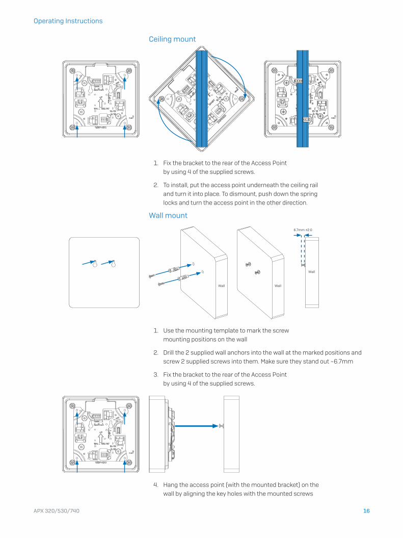
Ceiling mount
1. Fix the bracket to the rear of the Access Point
by using 4 of the supplied screws.
2. To install, put the access point underneath the ceiling rail
and turn it into place. To dismount, push down the spring
locks and turn the access point in the other direction.
Wall mount
1. Use the mounting template to mark the screw
mounting positions on the wall
2. Drill the 2 supplied wall anchors into the wall at the marked positions and
screw 2 supplied screws into them. Make sure they stand out ~6.7mm
3. Fix the bracket to the rear of the Access Point
by using 4 of the supplied screws.
4. Hang the access point (with the mounted bracket) on the
wall by aligning the key holes with the mounted screws

17APX 320/530/740
Operating Instructions
Flat ceiling mountTo mount your access point to a flat ceiling, please use the “flat ceiling & plenum
mounting kit” which is available as an option from your Sophos partner.
The kit consists of the following components:
Mounting instructions
1. Place the fix-plate on the rear of the Access Point. Make
sure it’s positioned in the right direction as indicated.
2. Install 4 step-screws (M3) from the supply into the bracket holes.
3. Fix the main bracket to a concrete ceiling by using 4 wall anchors and
screws or to a ceiling tile by using 4 screws and nuts (not supplied).
4. Align the Access Point (with fix-plate) via the key holes to the
main bracket and push it to the end in the sliding-slot.
Main bracket (to be fixed to the ceiling)
Keyholes
Screw holes for ceiling mount
Springs
4x M3 strep screws
Plenum mount clip plus 2x M4 screws and nuts
(not needed for ceiling mount)
Fix-plate (to be fixed to the rear of the access point)
Screw hole for product fixing
Spring lock
18APX 320/530/740
Operating Instructions
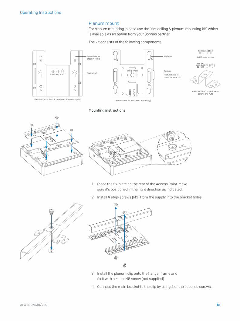
Plenum mountFor plenum mounting, please use the “flat ceiling & plenum mounting kit” which
is available as an option from your Sophos partner.
The kit consists of the following components:
Mounting instructions
1. Place the fix-plate on the rear of the Access Point. Make
sure it’s positioned in the right direction as indicated.
2. Install 4 step-screws (M3) from the supply into the bracket holes.
3. Install the plenum clip onto the hanger frame and
fix it with a M4 or M5 screw (not supplied)
4. Connect the main bracket to the clip by using 2 of the supplied screws.
Main bracket (to be fixed to the ceiling)
Keyholes
Springs
Feature holes for plenum mount clip
4x M3 strep screws
Plenum mount clip plus 2x M4 screws and nuts
Fix-plate (to be fixed to the rear of the access point)
Screw hole for product fixing
Spring lock
19APX 320/530/740
Operating Instructions
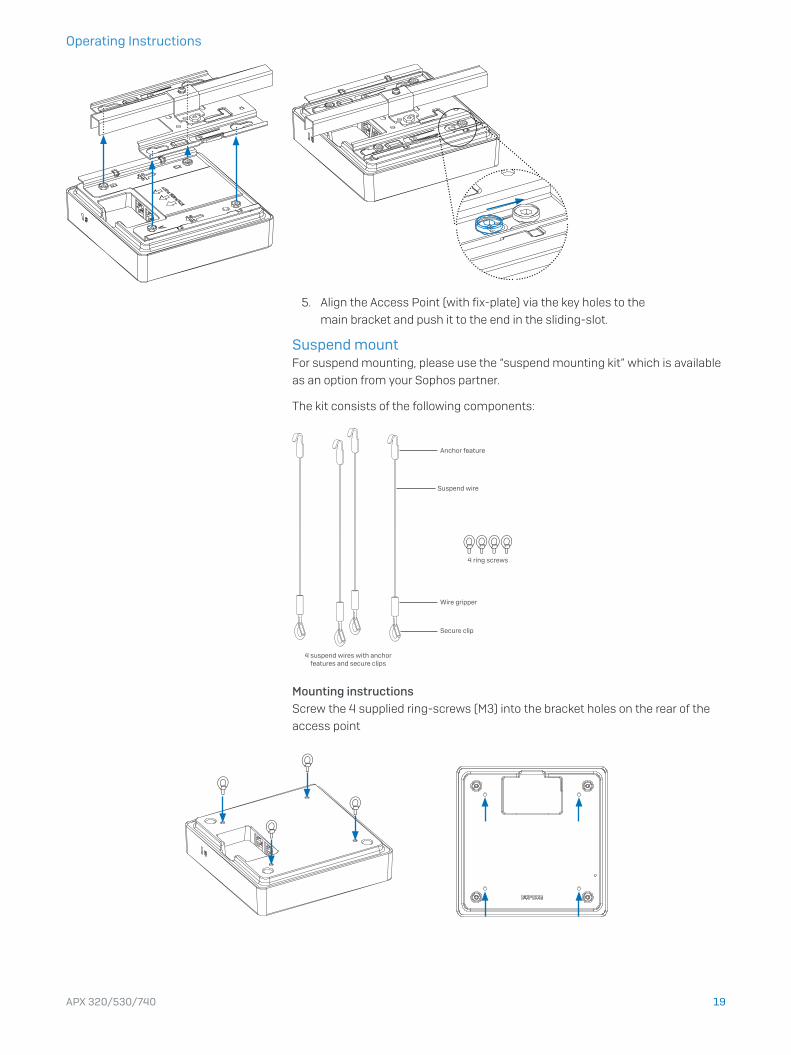
5. Align the Access Point (with fix-plate) via the key holes to the
main bracket and push it to the end in the sliding-slot.
Suspend mountFor suspend mounting, please use the “suspend mounting kit” which is available
as an option from your Sophos partner.
The kit consists of the following components:
Mounting instructionsScrew the 4 supplied ring-screws (M3) into the bracket holes on the rear of the
access point
4 ring screws
Anchor feature
Wire gripper
Suspend wire
Secure clip
4 suspend wires with anchor features and secure clips

20APX 320/530/740
Operating Instructions
Find a suitable place on the ceiling to hang the 4 suspend-wires by using the
anchor feature
Lift the AP up, open the secure-clips, attach the hooks to the rings, and release
the secure-clips to lock it
In order to adjust the height of the AP upwards, pull the end of the string further
out of the wire gripper. To adjust it downwards, press the top of the wire gripper to
release the wire first.
Pull end of string downwards
Press downwards to release string
Move string upwards
21APX 320/530/740
Operating Instructions
Armstrong interlude and silhouette mount
An optional mounting kit will be made available soon.
Serial Console ConnectionYou can connect a serial console to the RJ45 COM port of your Access Point.
For example, you can use the HyperTerminal program which is included with
most versions of Microsoft Windows to log onto the appliance console. Use an
appropriate adapter to connect the console to your hardware appliance.
The required connection settings are:
Ì Bits per second: 38,400
Ì Data bits: 8
Ì Parity: N (none)
Ì Stop bits: 1
Access via the serial console is activated by default on ttyS1.
Operating Instructions
United Kingdom and Worldwide SalesTel: +44 (0)8447 671131Email: [email protected]
North American SalesToll Free: 1-866-866-2802Email: [email protected]
Australia and New Zealand SalesTel: +61 2 9409 9100Email: [email protected]
Asia SalesTel: +65 62244168Email: [email protected]
© Copyright 2020. Sophos Ltd. All rights reserved.Registered in England and Wales No. 2096520, The Pentagon, Abingdon Science Park, Abingdon, OX14 3YP, UKSophos is the registered trademark of Sophos Ltd. All other product and company names mentioned are trademarks or registered trademarks of their respective owners.
2020-03-06 OINA (PC)


