
1
Arduino Internet Connectivity: Maintenance Manual
Julian Ryan
Draft No. 7
April 24, 2015
CEN 4935 Senior Software Engineering Project
Instructor: Dr. Janusz Zalewski
Software Engineering Program
Florida Gulf Coast University
Ft. Myers, FL 33965
2
1. Introduction
1.1 General Overview
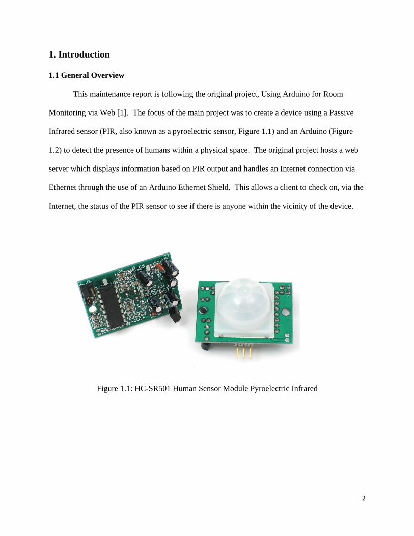
This maintenance report is following the original project, Using Arduino for Room
Monitoring via Web [1]. The focus of the main project was to create a device using a Passive
Infrared sensor (PIR, also known as a pyroelectric sensor, Figure 1.1) and an Arduino (Figure
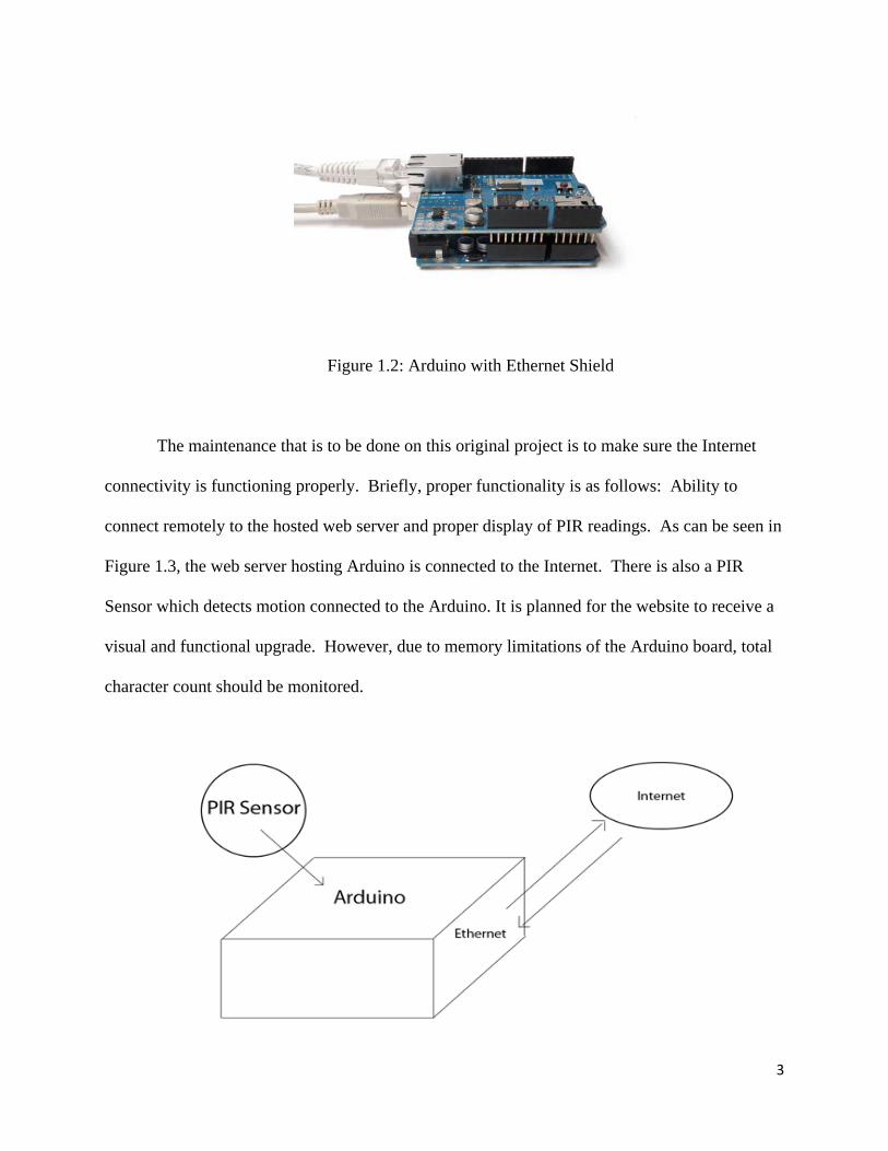
1.2) to detect the presence of humans within a physical space. The original project hosts a web
server which displays information based on PIR output and handles an Internet connection via
Ethernet through the use of an Arduino Ethernet Shield. This allows a client to check on, via the
Internet, the status of the PIR sensor to see if there is anyone within the vicinity of the device.
Figure 1.1: HC-SR501 Human Sensor Module Pyroelectric Infrared
3
Figure 1.2: Arduino with Ethernet Shield
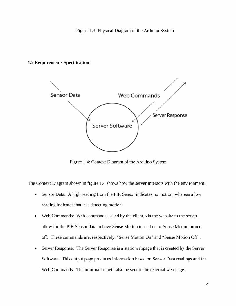
The maintenance that is to be done on this original project is to make sure the Internet
connectivity is functioning properly. Briefly, proper functionality is as follows: Ability to
connect remotely to the hosted web server and proper display of PIR readings. As can be seen in
Figure 1.3, the web server hosting Arduino is connected to the Internet. There is also a PIR
Sensor which detects motion connected to the Arduino. It is planned for the website to receive a
visual and functional upgrade. However, due to memory limitations of the Arduino board, total
character count should be monitored.
4
Figure 1.3: Physical Diagram of the Arduino System
1.2 Requirements Specification
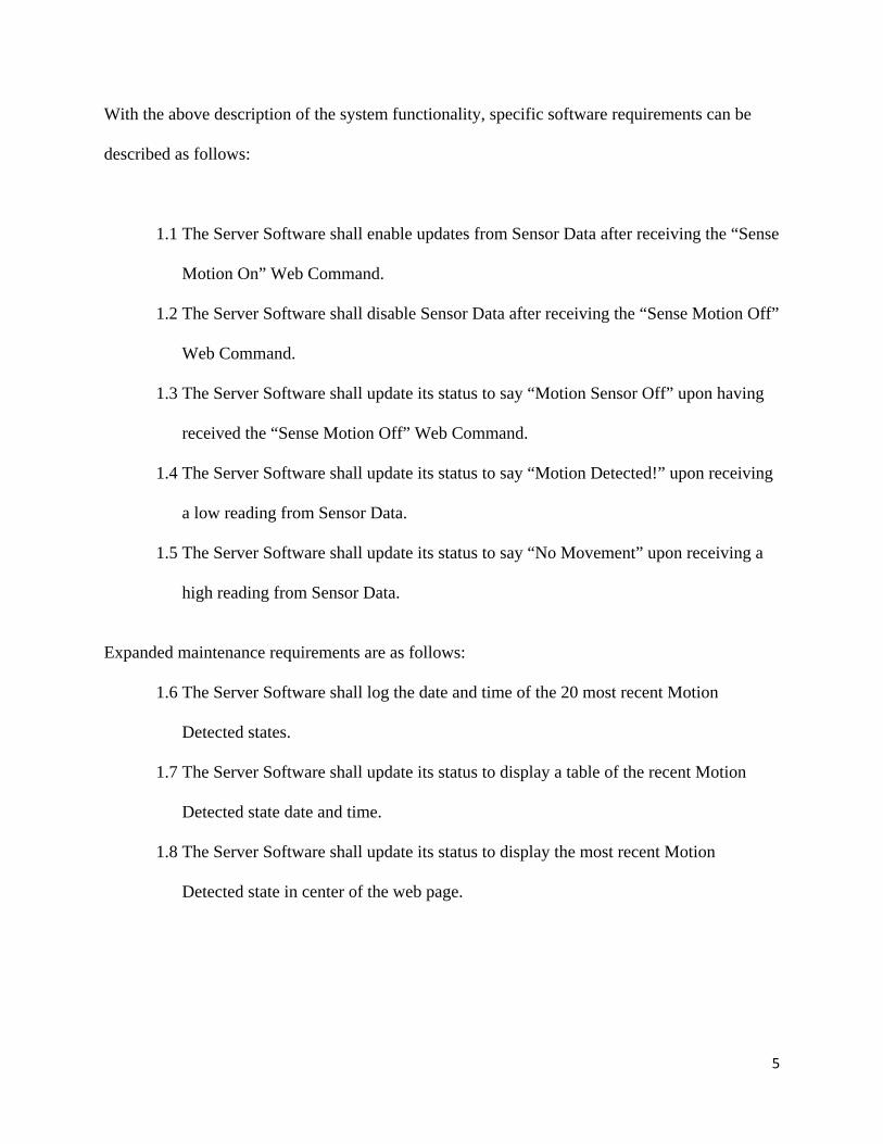
Figure 1.4: Context Diagram of the Arduino System
The Context Diagram shown in figure 1.4 shows how the server interacts with the environment:
Sensor Data: A high reading from the PIR Sensor indicates no motion, whereas a low
reading indicates that it is detecting motion.
Web Commands: Web commands issued by the client, via the website to the server,
allow for the PIR Sensor data to have Sense Motion turned on or Sense Motion turned
off. These commands are, respectively, “Sense Motion On” and “Sense Motion Off”.
Server Response: The Server Response is a static webpage that is created by the Server
Software. This output page produces information based on Sensor Data readings and the
Web Commands. The information will also be sent to the external web page.
5
With the above description of the system functionality, specific software requirements can be
described as follows:
1.1 The Server Software shall enable updates from Sensor Data after receiving the “Sense
Motion On” Web Command.
1.2 The Server Software shall disable Sensor Data after receiving the “Sense Motion Off”
Web Command.
1.3 The Server Software shall update its status to say “Motion Sensor Off” upon having
received the “Sense Motion Off” Web Command.
1.4 The Server Software shall update its status to say “Motion Detected!” upon receiving
a low reading from Sensor Data.
1.5 The Server Software shall update its status to say “No Movement” upon receiving a
high reading from Sensor Data.
Expanded maintenance requirements are as follows:
1.6 The Server Software shall log the date and time of the 20 most recent Motion
Detected states.
1.7 The Server Software shall update its status to display a table of the recent Motion
Detected state date and time.
1.8 The Server Software shall update its status to display the most recent Motion
Detected state in center of the web page.
6
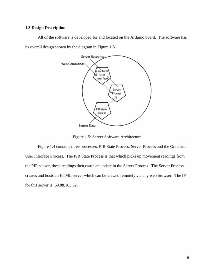
1.3 Design Description
All of the software is developed for and located on the Arduino board. The software has
its overall design shown by the diagram in Figure 1.5.
Figure 1.5: Server Software Architecture
Figure 1.4 contains three processes: PIR State Process, Server Process and the Graphical
User Interface Process. The PIR State Process is that which picks up movement readings from
the PIR sensor, these readings then cause an update in the Server Process. The Server Process
creates and hosts an HTML server which can be viewed remotely via any web browser. The IP
for this server is: 69.88.163.52.
7
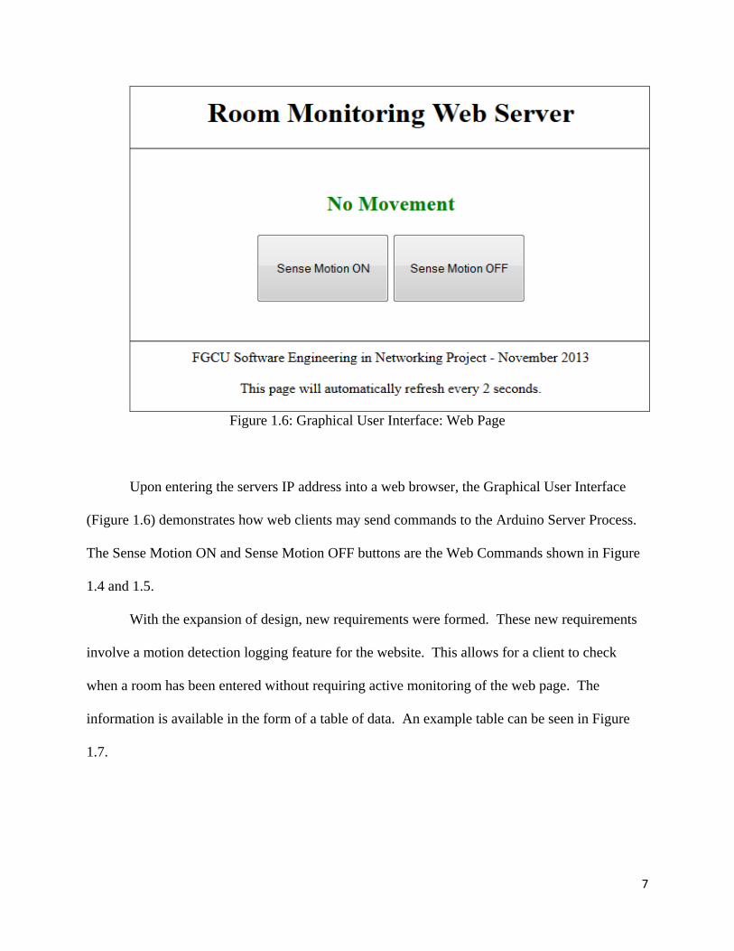
Figure 1.6: Graphical User Interface: Web Page
Upon entering the servers IP address into a web browser, the Graphical User Interface
(Figure 1.6) demonstrates how web clients may send commands to the Arduino Server Process.
The Sense Motion ON and Sense Motion OFF buttons are the Web Commands shown in Figure
1.4 and 1.5.
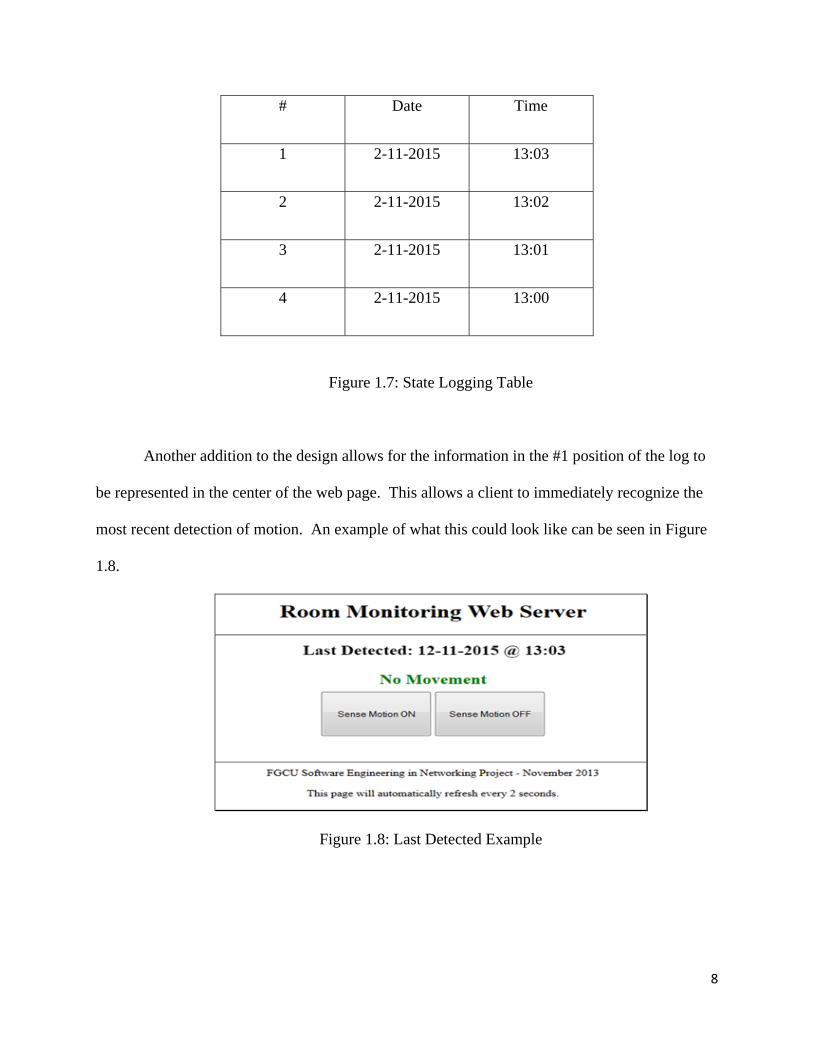
With the expansion of design, new requirements were formed. These new requirements
involve a motion detection logging feature for the website. This allows for a client to check
when a room has been entered without requiring active monitoring of the web page. The
information is available in the form of a table of data. An example table can be seen in Figure
1.7.
8
# Date Time
1 2-11-2015 13:03
2 2-11-2015 13:02
3 2-11-2015 13:01
4 2-11-2015 13:00
Figure 1.7: State Logging Table
Another addition to the design allows for the information in the #1 position of the log to
be represented in the center of the web page. This allows a client to immediately recognize the
most recent detection of motion. An example of what this could look like can be seen in Figure
1.8.
Figure 1.8: Last Detected Example
9
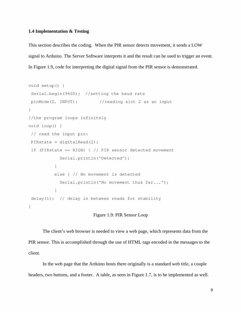
1.4 Implementation & Testing
This section describes the coding. When the PIR sensor detects movement, it sends a LOW
signal to Arduino. The Server Software interprets it and the result can be used to trigger an event.
In Figure 1.9, code for interpreting the digital signal from the PIR sensor is demonstrated.
void setup() {
Serial.begin(9600); //setting the baud rate
pinMode(2, INPUT); //reading slot 2 as an input
}
//the program loops infinitely
void loop() {
// read the input pin:
PIRstate = digitalRead(2);
if (PIRstate == HIGH) { // PIR sensor detected movement
Serial.println("Detected");
}
else { // No movement is detected
Serial.println("No movement thus far...");
}
delay(1); // delay in between reads for stability
}
Figure 1.9: PIR Sensor Loop
The client’s web browser is needed to view a web page, which represents data from the
PIR sensor. This is accomplished through the use of HTML tags encoded in the messages to the
client.
In the web page that the Arduino hosts there originally is a standard web title, a couple
headers, two buttons, and a footer. A table, as seen in Figure 1.7, is to be implemented as well.

10
The two buttons allow for the client to turn the motion sensing off or on. Figure 1.10
demonstrates how the buttons control the sensing of the PIR. The code in Figure 1.10 loops
infinitely, constantly updating whether the on-off switch is on or off.
int onOffSwitch = 0; ... if (onOffSwitch = HIGH) { // code for motion detection // see Figure 10 } ... // button functions client.println("<form method=get name=form>"); client.println("<button name=b value=1 type=submit>Sense Motion
On</button>"); client.println("<button name=b value=2 type=submit>Sense Motion
Off</button>"); client.println("</form><br />"); ... if (!strcmp(command, "1")) { onOffSwitch = 1; } else if (!strcmp(command, "2")) { onOffSwitch = 0; }
Figure 1.10: Code for On-Off Buttons
It should be noted that the web page is a static web page, instead of a dynamic or active
web page. This has implications in the overall implementation. In order to update the client on
any movement in the room, the Arduino has a need to constantly refresh the page. In the current
revision, the website has a refresh rate of 0.5 seconds.
With the addition of the logging table (Figure 1.7), there is a need to set system time so
that logged times are accurate. To do this, a connection with the time.nist.gov servers are
required upon initialization of the software. In this projects particular case, the NTP server
11
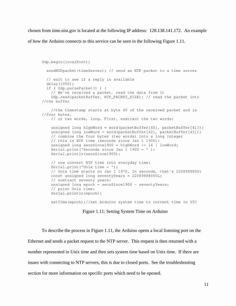
chosen from time.nist.gov is located at the following IP address: 128.138.141.172. An example
of how the Arduino connects to this service can be seen in the following Figure 1.11.
Udp.begin(localPort); sendNTPpacket(timeServer); // send an NTP packet to a time server // wait to see if a reply is available delay(1000); if ( Udp.parsePacket() ) { // We've received a packet, read the data from it Udp.read(packetBuffer, NTP_PACKET_SIZE); // read the packet into //the buffer //the timestamp starts at byte 40 of the received packet and is //four bytes, // or two words, long. First, esxtract the two words: unsigned long highWord = word(packetBuffer[40], packetBuffer[41]); unsigned long lowWord = word(packetBuffer[42], packetBuffer[43]); // combine the four bytes (two words) into a long integer // this is NTP time (seconds since Jan 1 1900): unsigned long secsSince1900 = highWord << 16 | lowWord; Serial.print("Seconds since Jan 1 1900 = " ); Serial.println(secsSince1900); // now convert NTP time into everyday time: Serial.print("Unix time = "); // Unix time starts on Jan 1 1970. In seconds, that's 2208988800: const unsigned long seventyYears = 2208988800UL; // subtract seventy years: unsigned long epoch = secsSince1900 - seventyYears; // print Unix time: Serial.println(epoch); setTime(epoch);//set Arduino system time to current time in UTC
Figure 1.11: Setting System Time on Arduino
To describe the process in Figure 1.11, the Arduino opens a local listening port on the
Ethernet and sends a packet request to the NTP server. This request is then returned with a
number represented in Unix time and then sets system time based on Unix time. If there are
issues with connecting to NTP servers, this is due to closed ports. See the troubleshooting
section for more information on specific ports which need to be opened.
12
Testing the software relies on checking the response when a person comes within a two
meter radius of the PIR sensor. When the radius is entered, what is to be observed is whether or
not software will respond. This can be viewed in two different ways. One method is referred to
as a local operation. The local operation is viewed through an LED that lights up in response to
a HIGH signal from the PIR sensor.
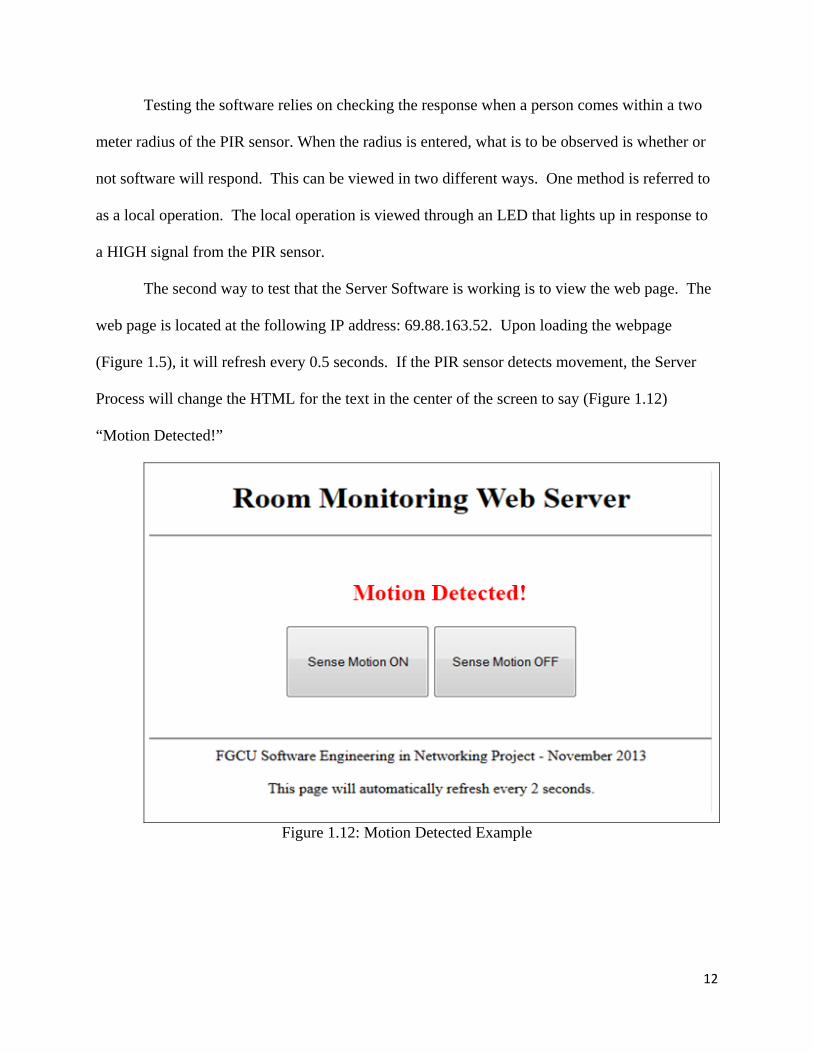
The second way to test that the Server Software is working is to view the web page. The
web page is located at the following IP address: 69.88.163.52. Upon loading the webpage
(Figure 1.5), it will refresh every 0.5 seconds. If the PIR sensor detects movement, the Server
Process will change the HTML for the text in the center of the screen to say (Figure 1.12)
“Motion Detected!”
Figure 1.12: Motion Detected Example

13
With the full implementation of the Server Software seen in Figure 1.13, a new test case
is needed, as it implements the motion logging table (Figure 1.7). Upon detecting movement, the
currently logged times are pushed down a position in the table, putting the newly detected date
into row #1. Testing of these features requires the tester to be testing both locally, due to the two
meter limitation of the PIR sensor, as well as remotely via the website to see the table update. A
successful test can be seen in Figure 1.13.
Figure 1.13: Successful Test of Server Software with Logging.
14
2. Maintenance Instructions
2.1 Developers Instructions
The hardware needs to be setup as follows:
Step 1: Plug Ethernet cable into Arduino Ethernet Shield Port and into Internet capable
Ethernet port.
Step 2: Plug power cable into Arduino Device.
For developing on the Arduino please see reference [2].
2.2 Operating Instructions
The following steps show how to operate the device remotely:
Step 1: Open a web browser.
Step 2: Enter IP address 69.88.163.52 into address bar.
Step 3: Click the Sense Motion On button.
15
3. Troubleshooting
The following are possible issues that can be encountered and, if possible, a resolution.
1. Arduino does not immediately update movement for a short moment after losing
movement. It is suggested that putting a resistor between the HR-501 sensor and the
PIN2 on the Arduino should help to reduce lag from inputs.
2. The PIR sensor has a limited range of around two meters. This can be an issue for
larger rooms. Even if there are people in the same room as the PIR sensor, it would
not be able to pick them up if they are outside of the mentioned two meter range.
Some solutions would be to have multiple PIR sensors or to use PIR sensors with a
larger radius. Another method would be to keep a sensor near the entrance of a door
which could log when a person entered the room and at what time rather than posting
real time data (log table can be seen in Figure 1.7).
3. If the web page is down, but the Arduino is online two things may have happened.
The first issue would be that the Arduino, on initialization of the web server, did not
establish a connection with the time.nist.gov server to synchronize system time with
real time. This is caused by the following unopened ports: TCP/UDP 123, TCP/UDP
13 and TCP/UDP 37. The second issue would be that TCP/UDP port 80 is unopened
and is disabling the web server from being accessed.
16
4. Conclusion
The Arduino PIR sensor software is suitable for small rooms that require real time motion
detection. This is provided that the device, as mentioned in the part two of the troubleshooting
section, be setup as suggested. The design meets all requirements as described in the Software
Requirements Specification section. However, just because requirements are met, does not mean
that there is no room for improvement. Further maintenance reports could incorporate more
powerful hardware which would allow for expansion of project features. A suggestion would be
to use a Raspberry Pi to host instead of an Arduino. This would give the developer a more
powerful device capable of hosting dynamic web pages as well as having larger logs.
17
5. References
[1] Serrano, Jessel. Using Arduino for Room Monitoring via Web. Ft. Myers, FL: Florida
Gulf Coast University Computer Science & Software Engineering, 2013.
[2] "Arduino – How To." Arduino. Arduino, n.d. Web. 18 February 2015.
<http://www.arduino.cc/en/Main/Howto>.

18
6. Appendix
The following (Pages 18-23) is the code for the full implementation of the updated Server
Software. It is loaded directly onto the Arduino via instructions available in section 2.1.
// this program uses an Arduino and an Arduino Ethernet Shield to host // a web page that displays if there is movement in a room. It detects // movement by reading the digital signal given off by a PIR sensor on // PIN2. #include <Time.h> #include <SPI.h> #include <Ethernet.h> #include <EthernetUdp.h> //Time Setup unsigned int localPort = 8888; // local port to listen for UDP packets char timeServer[] = " 128.138.141.172"; // time.nist.gov NTP server const int timeZone = -5; const int NTP_PACKET_SIZE= 48; // NTP time stamp is in the first 48 bytes of the message byte packetBuffer[ NTP_PACKET_SIZE]; //buffer to hold incoming and outgoing packets String timeString; const int loggerSize = 15; class dateHolder{ public: int s = 0; int m = 0; int h = 0; int d = 0; int mn = 0; int y = 0; dateHolder(){ } dateHolder(int s, int m, int h, int d, int mn, int y){ this->s = s; this->m = m; this->h = h; this->d = d; this->mn = mn; this->y = y; } };

19
// ethernet configuration byte mac[] = { 0x90, 0xA2, 0xDA, 0x0E, 0xD0, 0xE6 }; IPAddress ip(69,88,163,52); // IP address of Arduino EthernetServer server(80); // port 80 is default for HTTP EthernetUDP Udp; // initial int LED = 7; // led is connected to digital pin 7 int PIR = 2; // PIR sensor is connected to digital pin 2 int PIRstate = 0; // variable for PIR sensor status char c = 0; // received data char command[2] = "\0"; // command char onOffSwitch = 1; // switch for motion sensor // send an NTP request to the time server at the given address unsigned long sendNTPpacket(char* address) { // set all bytes in the buffer to 0 memset(packetBuffer, 0, NTP_PACKET_SIZE); // Initialize values needed to form NTP request packetBuffer[0] = 0b11100011; // LI, Version, Mode packetBuffer[1] = 0; // Stratum, or type of clock packetBuffer[2] = 6; // Polling Interval packetBuffer[3] = 0xEC; // Peer Clock Precision // 8 bytes of zero for Root Delay & Root Dispersion packetBuffer[12] = 49; packetBuffer[13] = 0x4E; packetBuffer[14] = 49; packetBuffer[15] = 52; // all NTP fields have been given values, now // you can send a packet requesting a timestamp: Udp.beginPacket(address, 123); //NTP requests are to port 123 Udp.write(packetBuffer, NTP_PACKET_SIZE); Udp.endPacket(); } void setup(){ Serial.begin(9600); Ethernet.begin(mac, ip); Serial.println(Ethernet.localIP()); Udp.begin(localPort); sendNTPpacket(timeServer); // send an NTP packet to a time server // wait to see if a reply is available delay(1000); if ( Udp.parsePacket() ) {
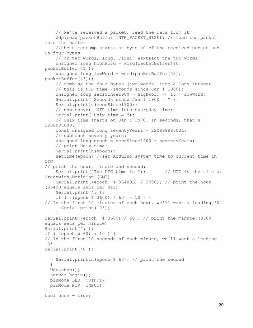
20
// We've received a packet, read the data from it Udp.read(packetBuffer, NTP_PACKET_SIZE); // read the packet into the buffer //the timestamp starts at byte 40 of the received packet and is four bytes, // or two words, long. First, esxtract the two words: unsigned long highWord = word(packetBuffer[40], packetBuffer[41]); unsigned long lowWord = word(packetBuffer[42], packetBuffer[43]); // combine the four bytes (two words) into a long integer // this is NTP time (seconds since Jan 1 1900): unsigned long secsSince1900 = highWord << 16 | lowWord; Serial.print("Seconds since Jan 1 1900 = " ); Serial.println(secsSince1900); // now convert NTP time into everyday time: Serial.print("Unix time = "); // Unix time starts on Jan 1 1970. In seconds, that's 2208988800: const unsigned long seventyYears = 2208988800UL; // subtract seventy years: unsigned long epoch = secsSince1900 - seventyYears; // print Unix time: Serial.println(epoch); setTime(epoch);//set Arduino system time to current time in UTC // print the hour, minute and second: Serial.print("The UTC time is "); // UTC is the time at Greenwich Meridian (GMT) Serial.print((epoch % 86400L) / 3600); // print the hour (86400 equals secs per day) Serial.print(':'); if ( ((epoch % 3600) / 60) < 10 ) { // In the first 10 minutes of each hour, we'll want a leading '0' Serial.print('0'); } Serial.print((epoch % 3600) / 60); // print the minute (3600 equals secs per minute) Serial.print(':'); if ( (epoch % 60) < 10 ) { // In the first 10 seconds of each minute, we'll want a leading '0' Serial.print('0'); } Serial.println(epoch % 60); // print the second } Udp.stop(); server.begin(); pinMode(LED, OUTPUT); pinMode(PIR, INPUT); } bool once = true;

21
time_t t; dateHolder detections[loggerSize]; void loop(){ if(once){ for(int n = 0; n < loggerSize; n++){ detections[n] = dateHolder(); } once = false; } EthernetClient client = server.available(); // detect if current is the first line boolean current_line_is_first = true; if (client) { // an http request ends with a blank line boolean current_line_is_blank = true; while (client.connected()) { if (client.available()) { char c = client.read(); // if we've gotten to the end of the line (received a newline // character) and the line is blank, the http request has ended, // so we can send a reply if (c == '\n' && current_line_is_blank) { // send a standard http response header client.println("HTTP/1.1 200 OK"); client.println("Content-Type: text/html"); client.println(); Serial.println(); // auto reload webpage every 2 second client.println("<META HTTP-EQUIV=REFRESH CONTENT=4 URL=>"); webpage title client.println("<center><p><h1>Room Monitoring Web Server </h1></p><center><hr><br />"); //latest detection
client.print("<p>Last Detected "); client.print(detections[0].mn); client.print("/");client.print(detections[0].d); client.print("/");client.print(detections[0].y); client.print(" @ "); client.print(detections[0].h);client.print(":"); client.print(detections[0].m); client.print(":"); client.print(detections[0].s); client.print(" UTC</p>");
// motion sensor is on if (onOffSwitch == HIGH) { // read digital pin 13 for the state of PIR sensor PIRstate = digitalRead(2); if (PIRstate == HIGH) { // PIR sensor detected movement client.println("<p><h2><font color=red>Motion Detected!</font></h2></p>"); }else{ // No movement is detected
22
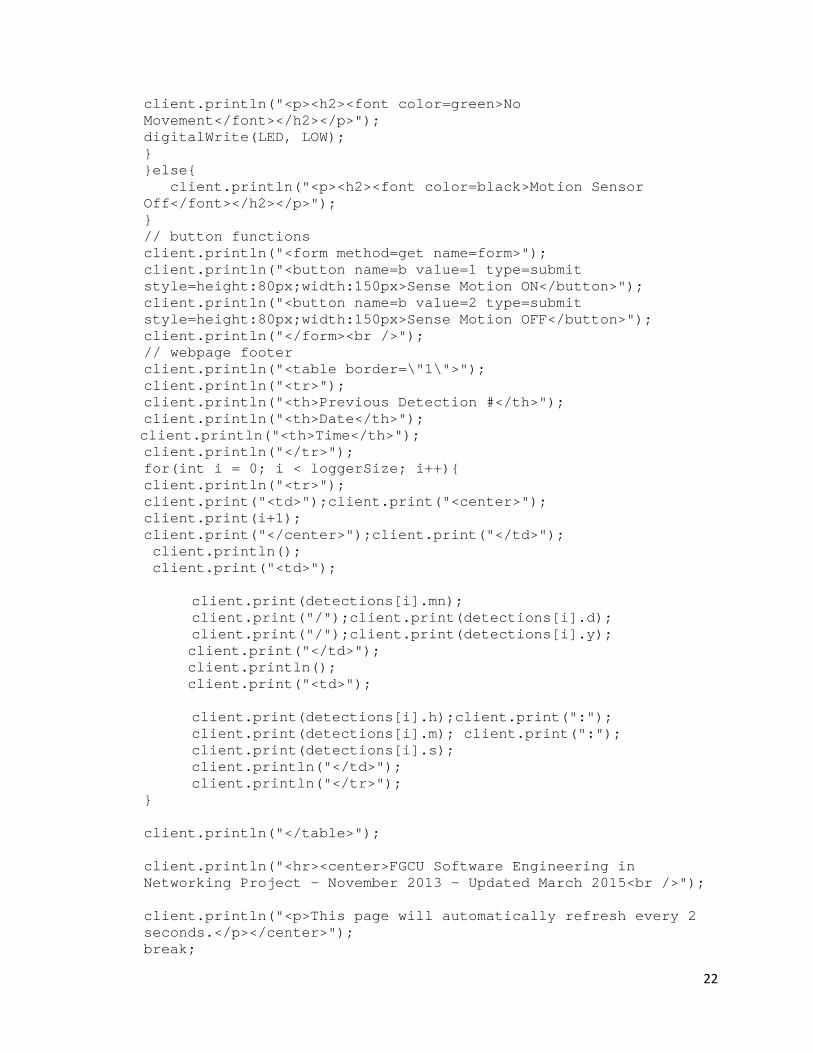
client.println("<p><h2><font color=green>No Movement</font></h2></p>"); digitalWrite(LED, LOW); } }else{ client.println("<p><h2><font color=black>Motion Sensor Off</font></h2></p>"); } // button functions client.println("<form method=get name=form>"); client.println("<button name=b value=1 type=submit style=height:80px;width:150px>Sense Motion ON</button>"); client.println("<button name=b value=2 type=submit style=height:80px;width:150px>Sense Motion OFF</button>"); client.println("</form><br />"); // webpage footer client.println("<table border=\"1\">"); client.println("<tr>"); client.println("<th>Previous Detection #</th>"); client.println("<th>Date</th>");
client.println("<th>Time</th>"); client.println("</tr>"); for(int i = 0; i < loggerSize; i++){ client.println("<tr>"); client.print("<td>");client.print("<center>"); client.print(i+1); client.print("</center>");client.print("</td>"); client.println(); client.print("<td>");
client.print(detections[i].mn); client.print("/");client.print(detections[i].d); client.print("/");client.print(detections[i].y);
client.print("</td>"); client.println(); client.print("<td>");
client.print(detections[i].h);client.print(":"); client.print(detections[i].m); client.print(":"); client.print(detections[i].s); client.println("</td>"); client.println("</tr>");
} client.println("</table>"); client.println("<hr><center>FGCU Software Engineering in Networking Project - November 2013 - Updated March 2015<br />"); client.println("<p>This page will automatically refresh every 2 seconds.</p></center>"); break;
23
} if (c == '\n') { // we're starting a new line current_line_is_first = false; current_line_is_blank = true; }else if (c != '\r') { // received a character that's a blank line current_line_is_blank = false; } // get the first http request if (current_line_is_first && c == '=') { for (int i = 0; i < 1; i++) { c = client.read(); command[i] = c; } // Motion Sensor control if (!strcmp(command, "1")) { onOffSwitch = 1; }else if (!strcmp(command, "2")) { onOffSwitch = 0; } } } } // give the web browser time to receive the data delay(1); client.stop(); }else{ PIRstate = digitalRead(2); if (PIRstate == HIGH && onOffButton == 1) { digitalWrite(LED, HIGH); for (int i = loggerSize - 1; i > 0; i--){ if( t+2 <= now() ){ detections[i] = detections[i - 1]; Serial.println(t); } } t = now(); detections[0] = dateHolder(second(), minute(), hour(), day(), month(), year()); }else{ // No movement is detected digitalWrite(LED, LOW); } delay(3); }
}


