Download - AVFM-II Manual Series A12
USER’S GUIDE
Installation & Operation Instructions
Area-Velocity Flow MeterModel AVFM-II
Manual Series A.12

Note: This page has been left blank intentionally.
IMPORTANT NOTE: This instrument is manufactured and calibrated to meet product specifications.Please read this manual carefully before installation and operation. Any unauthorized repairs ormodifications may result in a suspension of the warranty.
Available in Adobe Acrobat pdf format
Page 3
AVFM-II Area-Velocity Flow Meter
Manual Series A.12
INDEX
Function Test · · · · · · · · · · · · · · · · · · · · · · · · · · · · · · · · · · · · · · · · · · · · · · · · · · · · · 4Connections · · · · · · · · · · · · · · · · · · · · · · · · · · · · · · · · · · · · · · · · · · · · · · · · · · · · · · 4Keypad System · · · · · · · · · · · · · · · · · · · · · · · · · · · · · · · · · · · · · · · · · · · · · · · · · · · 4Menu - Flow Chart· · · · · · · · · · · · · · · · · · · · · · · · · · · · · · · · · · · · · · · · · · · · · · · · · 5Run· · · · · · · · · · · · · · · · · · · · · · · · · · · · · · · · · · · · · · · · · · · · · · · · · · · · · · · · · · · · · 7Totalizer · · · · · · · · · · · · · · · · · · · · · · · · · · · · · · · · · · · · · · · · · · · · · · · · · · · · · · · · 8Password · · · · · · · · · · · · · · · · · · · · · · · · · · · · · · · · · · · · · · · · · · · · · · · · · · · · · · · · 8Units / Mode · · · · · · · · · · · · · · · · · · · · · · · · · · · · · · · · · · · · · · · · · · · · · · · · · · · · · 9Calibration - for Open Channel Flow· · · · · · · · · · · · · · · · · · · · · · · · · · · · · · · · · · 124-20mA Outputs· · · · · · · · · · · · · · · · · · · · · · · · · · · · · · · · · · · · · · · · · · · · · · · · · · 13Relay Parameters · · · · · · · · · · · · · · · · · · · · · · · · · · · · · · · · · · · · · · · · · · · · · · · · · 14Special Functions · · · · · · · · · · · · · · · · · · · · · · · · · · · · · · · · · · · · · · · · · · · · · · · · · 15Sensor Location · · · · · · · · · · · · · · · · · · · · · · · · · · · · · · · · · · · · · · · · · · · · · · · · · · 17Enclosure Installation· · · · · · · · · · · · · · · · · · · · · · · · · · · · · · · · · · · · · · · · · · · · · · 21Field Troubleshooting · · · · · · · · · · · · · · · · · · · · · · · · · · · · · · · · · · · · · · · · · · · · · 23Sensor Cleaning Instructions · · · · · · · · · · · · · · · · · · · · · · · · · · · · · · · · · · · · · · · · 24Applications Hotline · · · · · · · · · · · · · · · · · · · · · · · · · · · · · · · · · · · · · · · · · · · · · · 25Product Return Procedure · · · · · · · · · · · · · · · · · · · · · · · · · · · · · · · · · · · · · · · · · · 26Warranty · · · · · · · · · · · · · · · · · · · · · · · · · · · · · · · · · · · · · · · · · · · · · · · · · · · · · · · 27Appendix A - Options · · · · · · · · · · · · · · · · · · · · · · · · · · · · · · · · · · · · · · · · · · · · · 28Data Logger · · · · · · · · · · · · · · · · · · · · · · · · · · · · · · · · · · · · · · · · · · · · · · · · · · · · · 34RS232C Serial Output · · · · · · · · · · · · · · · · · · · · · · · · · · · · · · · · · · · · · · · · · · · · · 40Conversion Guide · · · · · · · · · · · · · · · · · · · · · · · · · · · · · · · · · · · · · · · · · · · · · · · · 42Specifications· · · · · · · · · · · · · · · · · · · · · · · · · · · · · · · · · · · · · · · · · · · · · · · · · · · · 43
INTRODUCTION:
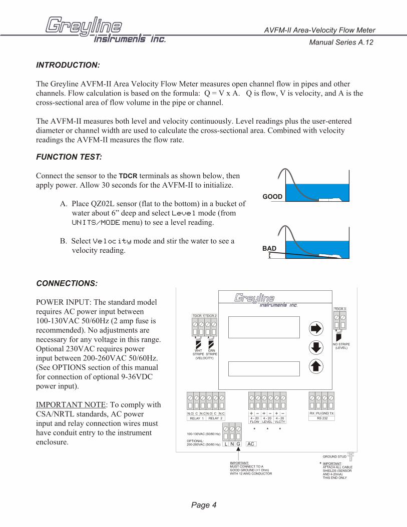
The Greyline AVFM-II Area Velocity Flow Meter measures open channel flow in pipes and other channels. Flow calculation is based on the formula: Q = V x A. Q is flow, V is velocity, and A is thecross-sectional area of flow volume in the pipe or channel.
The AVFM-II measures both level and velocity continuously. Level readings plus the user-entereddiameter or channel width are used to calculate the cross-sectional area. Combined with velocityreadings the AVFM-II measures the flow rate.
FUNCTION TEST:
Connect the sensor to the TDCR terminals as shown below, thenapply power. Allow 30 seconds for the AVFM-II to initialize.
A. Place QZ02L sensor (flat to the bottom) in a bucket ofwater about 6” deep and select Level mode (fromUNITS/MODE menu) to see a level reading.
B. Select Velocity mode and stir the water to see avelocity reading.
CONNECTIONS:
POWER INPUT: The standard modelrequires AC power input between100-130VAC 50/60Hz (2 amp fuse isrecommended). No adjustments arenecessary for any voltage in this range. Optional 230VAC requires powerinput between 200-260VAC 50/60Hz. (See OPTIONS section of this manualfor connection of optional 9-36VDCpower input).
IMPORTANT NOTE: To comply with CSA/NRTL standards, AC powerinput and relay connection wires musthave conduit entry to the instrumentenclosure.
Manual Series A.12
AVFM-II Area-Velocity Flow Meter
Page 4
BAD
GOOD
L N G AC
IMPORTANT:MUST CONNECT TO AGOOD GROUND (<1 Ohm)WITH 12 AWG CONDUCTOR
100-130VAC (50/60 Hz)
OPTIONAL:200-260VAC (50/60 Hz)
* * *
N.O C N.C N.O C N.C
RELAY 1 RELAY 2
RX PU GND TX
RS 2324 - 20FLOW
4 - 20VLCTY
GROUND STUD
IMPORTANT:ATTACH ALL CABLE SHIELDS (SENSORAND 4-20mA)THIS END ONLY
*
TDCR.3
TDCR.1 TDCR.2
WHTSTRIPE
GRNSTRIPE
(VELOCITY)
NO STRIPE(LEVEL)
4 - 20LEVEL
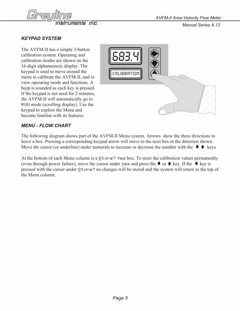
KEYPAD SYSTEM
The AVFM-II has a simple 3-buttoncalibration system. Operating andcalibration modes are shown on the16-digit alphanumeric display. Thekeypad is used to move around themenu to calibrate the AVFM-II, and toview operating mode and functions. Abeep is sounded as each key is pressed.If the keypad is not used for 2 minutes,the AVFM-II will automatically go toRUN mode (scrolling display). Use thekeypad to explore the Menu andbecome familiar with its features.
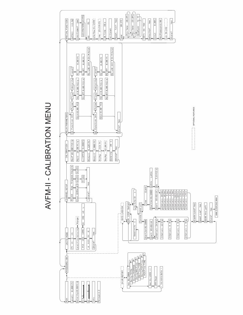
MENU - FLOW CHART
The following diagram shows part of the AVFM-II Menu system. Arrows show the three directions toleave a box. Pressing a corresponding keypad arrow will move to the next box in the direction shown.Move the cursor (or underline) under numerals to increase or decrease the number with the È Ç keys.
At the bottom of each Menu column is a Store? Yes box. To store the calibration values permanently (even through power failure), move the cursor under Yes and press the È or Ç key. If the È key ispressed with the cursor under Store? no changes will be stored and the system will return to the top of the Menu column.
AVFM-II Area-Velocity Flow Meter
Manual Series A.12
Page 5
PA
SS
WO
RD
: 0
0
OP
TIO
NA
L F
EA
TU
RE
S
RU
N
2
4 H
R R
EP
OR
T
J
an
0
1/
20
00
-
>
D
ai
ly
TO
TA
L
D
ai
ly
AV
ER
AG
E
D
ai
ly
MA
X F
lo
w
M
AX
Fl
ow
TI
ME
D
ai
ly
MI
N F
lo
w
M
IN
Fl
ow
TI
ME
D
ec
31
/1
99
9 -
>
2
55
Da
ys
-
no
mo
re
da
ta
-
AV
FM
-II -
CA
LIB
RA
TIO
N M
EN
U
Ve
lo
ci
ty
:0
.0
0f
t/
s
Le
ve
l:
0
.0
00
ft
C
AL
IB
RA
TI
ON
D
AT
A L
OG
GI
NG
Lo
g S
it
e I
D 1
Se
ss
io
n N
o 1 F
or
mt
d T
re
nd
L
VT
RU
N S
TO
P S
et
up
St
ar
tJ
an
01
/2
00
0
St
ar
t 0
3:
02
:1
6
In
te
rv
al
: 2
4 H
rs
In
te
rv
al
: 1
2 H
rs
In
te
rv
al
: 1
H
rs
Ti
me
E
ve
nt H
iA
lm
L
oA
lm
At
: 5
.0
ft
3/
s
St
ar
tJ
an
01
/2
00
0
St
ar
t
03
:0
2:
16
In
te
rv
al
: 8
H
rs
In
te
rv
al
: 4
H
rs
In
te
rv
al
:
30
Se
c
In
te
rv
al
:
10
Se
c
In
te
rv
al
:
5
Se
c
In
te
rv
al
:
2
Se
c
In
te
rv
al
:
1
Se
c
In
te
rv
al
: 3
0 M
in
In
te
rv
al
: 1
0 M
in
In
te
rv
al
:
5 M
in
In
te
rv
al
:
2 M
in
In
te
rv
al
:
1 M
in
**
* S
TO
RI
NG
**
*
Re
se
t L
og
? Y
es
26
64
0 H
rs
L
ef
t
St
or
e?
Y
es
Wr
ap
Ar
ou
nd
? Y
es
St
or
e?
Y
es
CH
AN
NE
L S
ET
UP
Ro
un
d
Wi
dt
hW
id
th
U
NI
TS
/M
OD
E
ft
i
n m
c
m
Ra
ng
e
St
or
e?
Y
es
ft
3 U
SG
U
SM
GI
G I
MG
m
3 L
s m
in
h
r d
Ch
an
ID
Sq
ua
re
Le
ve
l F
lo
w V
el
oc
it
y
Tr
ap
ez
d
Sl
op
e
Eg
g
He
ig
ht
Ma
xV
1
0.
00
ft
/s
Ma
xF
10
.0
00
ft
3/
s
Mi
nR
g 1
.3
33
ft
Ma
xR
g 3
2.
00
ft
Da
mp
in
g 2
0 %
St
or
e?
Y
es
Ma
xL
vl
3
.0
00
ft
Mi
nL
vl
0
.1
25
ft
Re
la
ys
:1
2
To
t:
SC
v
EC
8
SP
EC
IA
L F
UN
CT
IO
N
AV
FM
II
V
2.
92
RE
LA
Y P
AR
AM
ET
ER
S
Pu
ls
eR
1 F
un
ct
io
n O
ff
R1
on
0.
00
f
t3
Fl
ow
R1
on
0.
00
ft
3/
s
R1
OF
F 0
.0
0 f
t3
/s
R1
L
OE
O
ff
On
St
or
e?
Y
es
Ho
ld
Ta
g 0
1
Da
te
Ma
y 3
1/
19
99
Ti
me
2
3:
39
:5
1
Vi
ew
Co
de
s?
Ye
s
12
34
56
78
90
12
34
56
LO
E T
im
e 3
0 s
Re
se
t T
ot
? Y
es
Te
mp
20
.3
Cº
Mi
n T
em
p 2
0.
0Cº
Ma
x T
em
p 2
3.
0Cº
DI
SP
LA
Y
C
Fº
º
Ca
l C
on
st
Ve
lo
ci
ty
Le
ve
l
Fl
ow
Ve
lo
ci
ty
R1
on
0
.0
0 f
t
R1
OF
F
0.
00
ft
Pu
ls
eR
2 F
un
ct
io
n O
ff
R2
on
0.
00
f
t3
R2
on
0.
00
ft
3/
s
R2
OF
F 0
.0
0 f
t3
/s
R2
L
OE
O
ff
On
Ho
ld
Le
ve
l
R2
on
0.
00
ft
R2
OF
F 0
.0
0 f
t
IS
B?
: N
o
Ye
s
De
fa
ul
ts
?
Ye
s
Si
mu
l 0
.0
0%
Ne
w P
as
sw
or
d:
00
Co
m 9
6 1
92
St
or
e?
Ye
s
Lv
lO
FF
SE
T 0
.0
00
ft
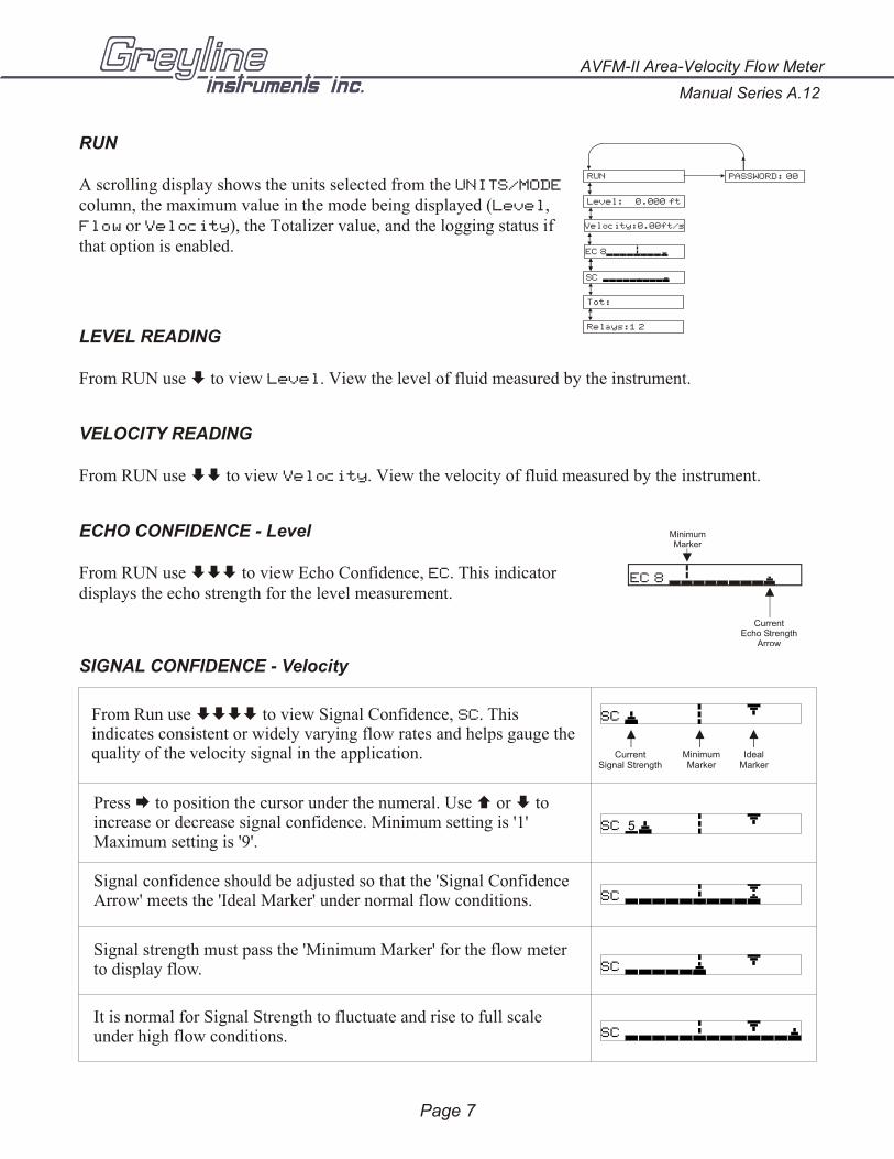
RUN
A scrolling display shows the units selected from the UNITS/MODE
column, the maximum value in the mode being displayed (Level,Flow or Velocity), the Totalizer value, and the logging status ifthat option is enabled.
LEVEL READING
From RUN use È to view Level. View the level of fluid measured by the instrument.
VELOCITY READING
From RUN use ÈÈ to view Velocity. View the velocity of fluid measured by the instrument.
ECHO CONFIDENCE - Level
From RUN use ÈÈÈ to view Echo Confidence, EC. This indicatordisplays the echo strength for the level measurement.
SIGNAL CONFIDENCE - Velocity
AVFM-II Area-Velocity Flow Meter
Manual Series A.12
Page 7
CurrentEcho Strength
Arrow
MinimumMarker
EC 8
PASSWORD: 00RUN
Velocity:0.00ft/s
Level: 0.000 ft
Relays:1 2
Tot:
SC v
EC 8
SC
CurrentSignal Strength
MinimumMarker
IdealMarker
SC 5
SCv
SCv
SCv
Press Æ to position the cursor under the numeral. Use Ç or È to increase or decrease signal confidence. Minimum setting is '1' Maximum setting is '9'.
Signal confidence should be adjusted so that the 'Signal Confidence Arrow' meets the 'Ideal Marker' under normal flow conditions.
Signal strength must pass the 'Minimum Marker' for the flow meter to display flow.
It is normal for Signal Strength to fluctuate and rise to full scale under high flow conditions.
From Run use ÈÈÈÈ to view Signal Confidence, SC. This indicates consistent or widely varying flow rates and helps gauge the quality of the velocity signal in the application.
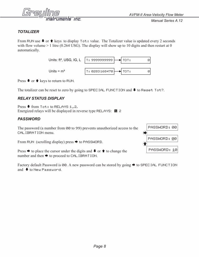
TOTALIZER
From RUN use È or Ç keys to display Tot: value. The Totalizer value is updated every 2 secondswith flow volume > 1 litre (0.264 USG). The display will show up to 10 digits and then restart at 0automatically.
Press È or Ç keys to return to RUN.
The totalizer can be reset to zero by going to SPECIAL FUNCTION and È to Reset Tot?.
RELAY STATUS DISPLAY
Press È from Tot: to RELAYS 1,2.Energized relays will be displayed in reverse type RELAYS:
PASSWORD
The password (a number from 00 to 99) prevents unauthorized access to theCALIBRATION menu.
From RUN (scrolling display) press Æ to PASSWORD.
Press Æ to place the cursor under the digits and È or Ç to change thenumber and then Æ to proceed to CALIBRATION.
Factory default Password is 00. A new password can be stored by going Æ to SPECIAL FUNCTION
and È to New Password.
Manual Series A.12
AVFM-II Area-Velocity Flow Meter
Page 8
1 3 2
T: 9999999999
T: 0283168470
TOT: 0
TOT: 0
Units: ft³, USG, IG, L
Units = m³
PASSWORD: 00
PASSWORD: 00
PASSWORD: 10
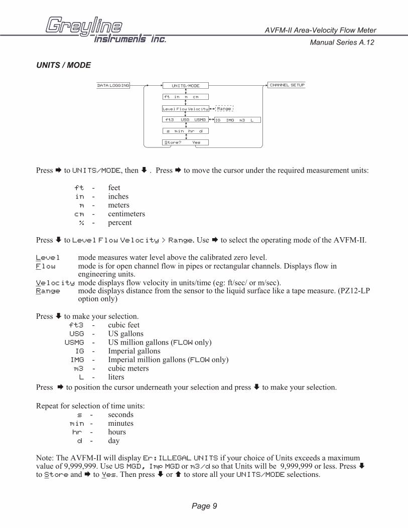
UNITS / MODE
Press Æ to UNITS/MODE, then È . Press Æ to move the cursor under the required measurement units:
ft - feetin - inches
m - meterscm - centimeters
% - percent
Press È to Level Flow Velocity > Range. Use Æ to select the operating mode of the AVFM-II.
Level mode measures water level above the calibrated zero level.Flow mode is for open channel flow in pipes or rectangular channels. Displays flow in
engineering units.Velocity mode displays flow velocity in units/time (eg: ft/sec/ or m/sec).Range mode displays distance from the sensor to the liquid surface like a tape measure. (PZ12-LP
option only)
Press È to make your selection.ft3 - cubic feetUSG - US gallons
USMG - US million gallons (FLOW only)IG - Imperial gallons
IMG - Imperial million gallons (FLOW only)m3 - cubic meters
L - liters
Press Æ to position the cursor underneath your selection and press È to make your selection.
Repeat for selection of time units:s - seconds
min - minuteshr - hours
d - day
Note: The AVFM-II will display Er:ILLEGAL UNITS if your choice of Units exceeds a maximumvalue of 9,999,999. Use US MGD, Imp MGD or m3/d so that Units will be 9,999,999 or less. Press Èto Store and Æ to Yes. Then press È or Ç to store all your UNITS/MODE selections.
AVFM-II Area-Velocity Flow Meter
Manual Series A.12
Page 9
DATA LOGGING CHANNEL SETUP UNITS/MODE
ft in m cm
Store? Yes
ft3 USG USMG IG IMG m3 L
s min hr d
RangeLevel Flow Velocity
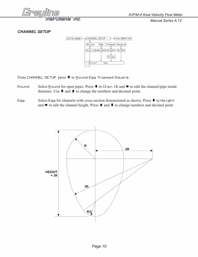
CHANNEL SETUP
From CHANNEL SETUP press È to Round Egg Trapezd Square.
Round Select Round for open pipes. Press È to Chan ID and Æ to edit the channel/pipe insidediameter. Use È and Ç to change the numbers and decimal point.
Egg Select Egg for channels with cross-section dimensioned as shown. Press È to Height
and Æ to edit the channel height. Press Ç and È to change numbers and decimal point.
Page 10
Manual Series A.12
AVFM-II Area-Velocity Flow Meter
R
3R
R/2
2R
HEIGHT= 3R
CALIBRATION
Store? Yes
CHANNEL SETUP
Round
Width Width
UNITS/MODE
Chan ID
SquareTrapezd
Slope
Egg
Height
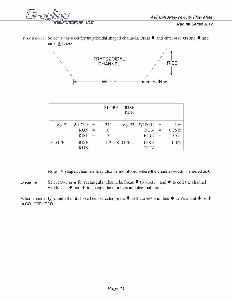
Trapezoid Select Trapezd for trapezoidal shaped channels. Press È and enter Width and È andenter Slope
Note - V shaped channels may also be monitored where the channel width is entered as 0.
Square Select Square for rectangular channels. Press È to Width and Æ to edit the channelwidth. Use È and Ç to change the numbers and decimal point.
When channel type and all units have been selected press È to Store? and then Æ to Yes and È or Çto CALIBRATION.
Page 11
AVFM-II Area-Velocity Flow Meter
Manual Series A.12
SLOPE = RISERUN
e.g.#1 WIDTHRUNRISE
===
24"10"12"
e.g.#2 WIDTHRUNRISE
===
1 m0.35 m0.5 m
SLOPE = RISERUN
= 1.2 SLOPE = RISERUN
= 1.429
TRAPEZOIDALCHANNEL
RUNWIDTH
RISE

CALIBRATION
From CALIBRATION press È to MaxF. Enter the maximum expected flow in your application. If themaximum expected flow is unknown, enter an estimated value.
Note: MaxF entry is only required to calibrate 20mA output at your maximum flow rate.
Press È to MaxV. Enter the maximum expected flow velocity in your application. If the maximumvelocity is unknown, enter an estimated value, e.g. 10 ft/s.
Note: MaxV entry is only required to calibrate velocity at 20mA output and to set the maximumvelocity measured in LVT logging mode.
Press È to LvlOFFSET. Set to 0.00 when sensor is mounted on the floor of the channel. When sensor is mounted above the floor of the channel enter the distance between channel floor and bottom of sensor.
Note: 4mA is not affected by LvlOFFSET settings. 4mA is the bottom of the channel or pipe.
Manual Series A.12
AVFM-II Area-Velocity Flow Meter
Page 12
RELAY PARAMETERSCHANNEL SETUP CALIBRATION
MaxV 10.00 ft/s
MaxF 10.000 ft3/s
MinRg 1.333 ft
MaxRg 32.00 ft
Damping 20 %
Store? Yes
MaxLvl 3.000 ft
MinLvl 0.125 ft
LvlOFFSET 0.000ft
SENSOR
END VIEWSIDE VIEW
TOP VIEW
SENSOR
U-SHAPE STAINLESS STEEL18 GA. RECOMMENDEDHEIGHT AS REQUIRED
USE THE MB-QZ STAINLESS STEELMOUNTING BRACKET(SUPPLIED)
SENSOR ELEVATED ABOVE FLOOR OF PIPE OR CHANNEL
LEVELSENSOR
Press È to MinLvl. Minimum level threshold. When the fluid “head” drops below MinLvl the flowmeasurement is forced to zero (4mA). MinLvl can be set between 1” and 6” (25.4 and 152.4 mm)above LvlOFFSET setting.
Press È to MaxLvl. Enter the maximum expected level in your application. If the maximum level isunknown, enter an estimated value, e.g. 6 ft.
Note: MaxLvl entry is only required to calibrate the level at 20mA output and to set the maximum
level measured in LVT logging mode.
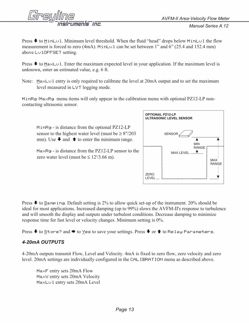
MinRg /MaxRg menu items will only appear in the calibration menu with optional PZ12-LP non-contacting ultrasonic sensor.
MinRg - is distance from the optional PZ12-LP
sensor to the highest water level (must be ≥ 8"/203mm). Use È and Ç to enter the minimum range.
MaxRg - is distance from the PZ12-LP sensor to the
zero water level (must be ≤ 12'/3.66 m).
Press È to Damping. Default setting is 2% to allow quick set-up of the instrument. 20% should beideal for most applications. Increased damping (up to 99%) slows the AVFM-II's response to turbulenceand will smooth the display and outputs under turbulent conditions. Decrease damping to minimizeresponse time for fast level or velocity changes. Minimum setting is 0%.
Press È to Store? and Æ to Yes to save your settings. Press È or Ç to Relay Parameters.
4-20mA OUTPUTS
4-20mA outputs transmit Flow, Level and Velocity. 4mA is fixed to zero flow, zero velocity and zerolevel. 20mA settings are individually configured in the CALIBRATION menu as described above.
MaxF entry sets 20mA FlowMaxV entry sets 20mA VelocityMaxLvl entry sets 20mA Level
AVFM-II Area-Velocity Flow Meter
Manual Series A.12
Page 13
SENSOR
ZEROLEVEL
MAXRANGE
MAX LEVEL
MINRANGE
OPTIONAL PZ12-LPULTRASONIC LEVEL SENSOR
RELAY PARAMETERS
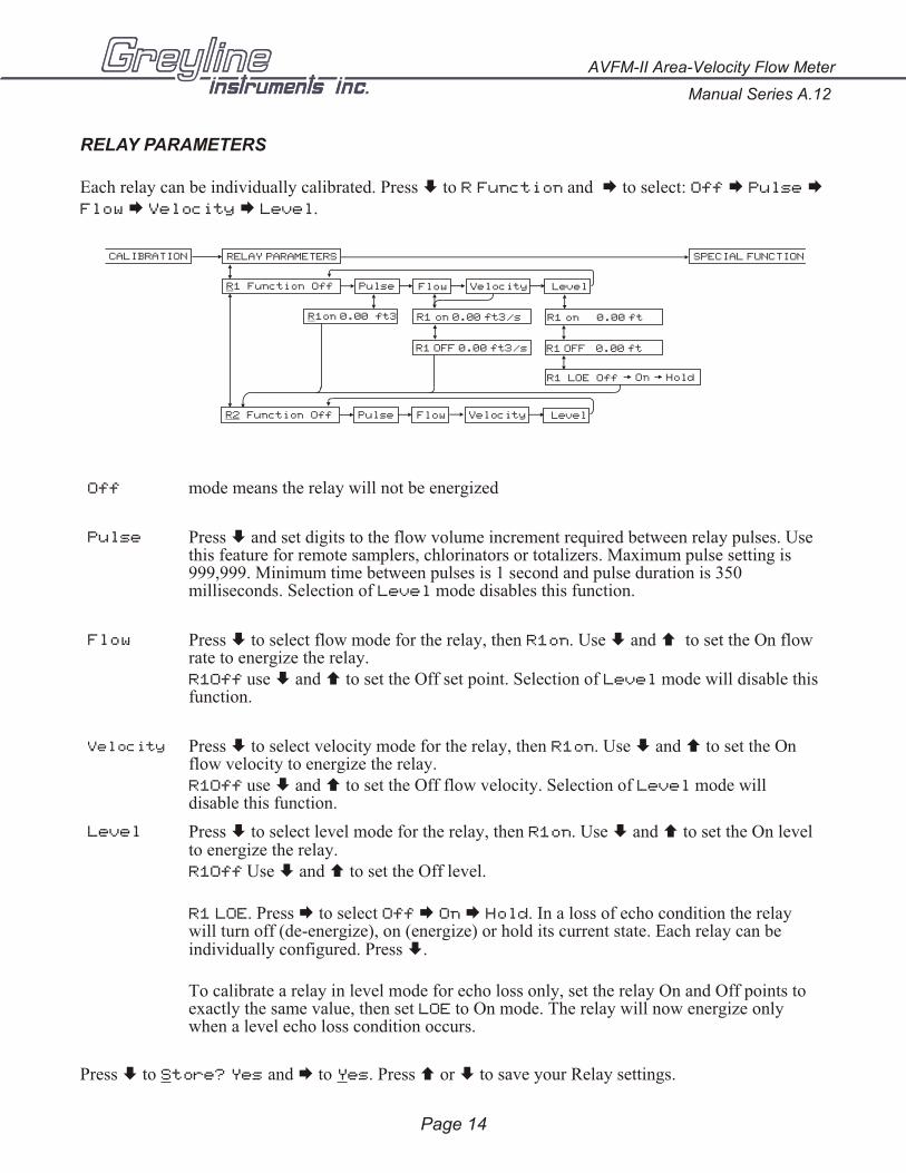
Each relay can be individually calibrated. Press È to R Function and Æ to select: Off Æ Pulse ÆFlow Æ Velocity Æ Level.
Off mode means the relay will not be energized
Pulse Press È and set digits to the flow volume increment required between relay pulses. Usethis feature for remote samplers, chlorinators or totalizers. Maximum pulse setting is999,999. Minimum time between pulses is 1 second and pulse duration is 350milliseconds. Selection of Level mode disables this function.
Flow Press È to select flow mode for the relay, then R1on. Use È and Ç to set the On flowrate to energize the relay. R1Off use È and Ç to set the Off set point. Selection of Level mode will disable this function.
Velocity Press È to select velocity mode for the relay, then R1on. Use È and Ç to set the Onflow velocity to energize the relay.R1Off use È and Ç to set the Off flow velocity. Selection of Level mode willdisable this function.
Level Press È to select level mode for the relay, then R1on. Use È and Ç to set the On levelto energize the relay.R1Off Use È and Ç to set the Off level.
R1 LOE. Press Æ to select Off Æ On Æ Hold. In a loss of echo condition the relaywill turn off (de-energize), on (energize) or hold its current state. Each relay can beindividually configured. Press È.
To calibrate a relay in level mode for echo loss only, set the relay On and Off points toexactly the same value, then set LOE to On mode. The relay will now energize onlywhen a level echo loss condition occurs.
Press È to Store? Yes and Æ to Yes. Press Ç or È to save your Relay settings.
Manual Series A.12
AVFM-II Area-Velocity Flow Meter
Page 14
CALIBRATION SPECIAL FUNCTIONRELAY PARAMETERS
PulseR1 Function Off
R1on 0.00 ft3
Flow
R1 on 0.00 ft3/s
R1 OFF 0.00 ft3/s
R1 LOE Off On Hold
Velocity Level
Flow Velocity
R1 on 0.00 ft
R1 OFF 0.00 ft
PulseR2 Function Off Level
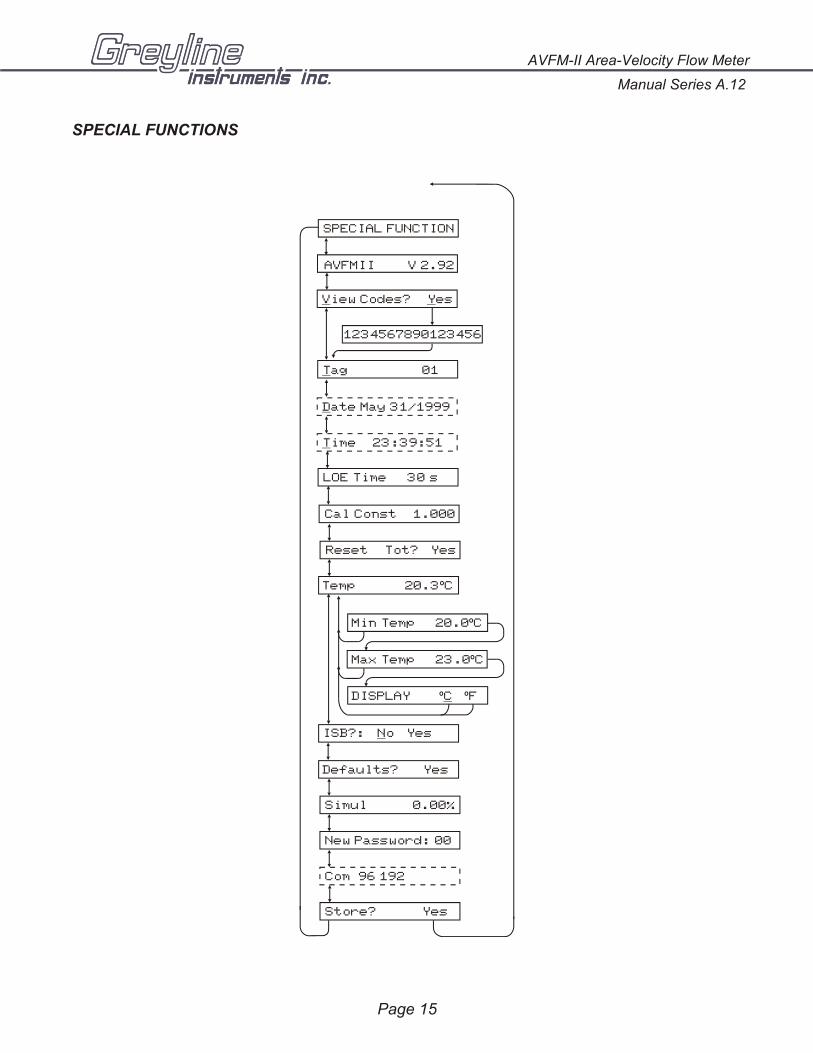
SPECIAL FUNCTIONS
AVFM-II Area-Velocity Flow Meter
Manual Series A.12
Page 15
SPECIAL FUNCTION
AVFMII V 2.92
Tag 01
Date May 31/1999
Time 23:39:51
View Codes? Yes
1234567890123456
LOE Time 30 s
Reset Tot? Yes
Temp 20.3 Cº
Min Temp 20.0 Cº
Max Temp 23.0 Cº
DISPLAY C Fº º
Cal Const 1.000
ISB?: No Yes
Defaults? Yes
Simul 0.00%
New Password: 00
Com 96 192
Store? Yes
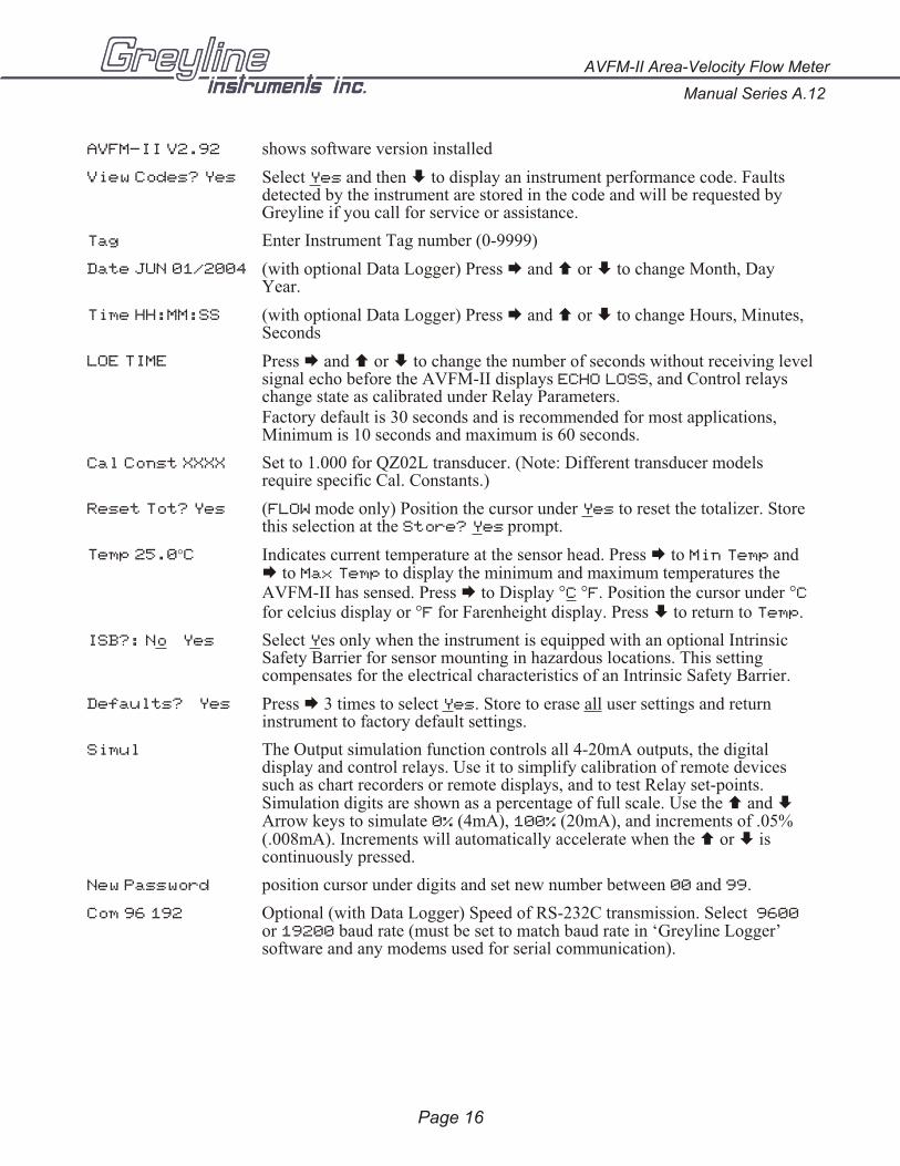
AVFM-II V2.92 shows software version installed
View Codes? Yes Select Yes and then È to display an instrument performance code. Faultsdetected by the instrument are stored in the code and will be requested byGreyline if you call for service or assistance.
Tag Enter Instrument Tag number (0-9999)
Date JUN 01/2004 (with optional Data Logger) Press Æ and Ç or È to change Month, DayYear.
Time HH:MM:SS (with optional Data Logger) Press Æ and Ç or È to change Hours, Minutes,Seconds
LOE TIME Press Æ and Ç or È to change the number of seconds without receiving level signal echo before the AVFM-II displays ECHO LOSS, and Control relayschange state as calibrated under Relay Parameters.Factory default is 30 seconds and is recommended for most applications,Minimum is 10 seconds and maximum is 60 seconds.
Cal Const XXXX Set to 1.000 for QZ02L transducer. (Note: Different transducer modelsrequire specific Cal. Constants.)
Reset Tot? Yes (FLOW mode only) Position the cursor under Yes to reset the totalizer. Storethis selection at the Store? Yes prompt.
Temp 25.0°C Indicates current temperature at the sensor head. Press Æ to Min Temp andÆ to Max Temp to display the minimum and maximum temperatures theAVFM-II has sensed. Press Æ to Display °C °F. Position the cursor under °Cfor celcius display or °F for Farenheight display. Press È to return to Temp.
ISB?: No Yes Select Yes only when the instrument is equipped with an optional IntrinsicSafety Barrier for sensor mounting in hazardous locations. This settingcompensates for the electrical characteristics of an Intrinsic Safety Barrier.
Defaults? Yes Press Æ 3 times to select Yes. Store to erase all user settings and returninstrument to factory default settings.
Simul The Output simulation function controls all 4-20mA outputs, the digitaldisplay and control relays. Use it to simplify calibration of remote devicessuch as chart recorders or remote displays, and to test Relay set-points.Simulation digits are shown as a percentage of full scale. Use the Ç and ÈArrow keys to simulate 0% (4mA), 100% (20mA), and increments of .05%(.008mA). Increments will automatically accelerate when the Ç or È iscontinuously pressed.
New Password position cursor under digits and set new number between 00 and 99.
Com 96 192 Optional (with Data Logger) Speed of RS-232C transmission. Select 9600or 19200 baud rate (must be set to match baud rate in ‘Greyline Logger’software and any modems used for serial communication).
Manual Series A.12
AVFM-II Area-Velocity Flow Meter
Page 16
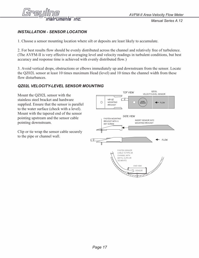
INSTALLATION - SENSOR LOCATION
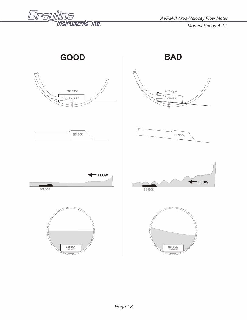
1. Choose a sensor mounting location where silt or deposits are least likely to accumulate.
2. For best results flow should be evenly distributed across the channel and relatively free of turbulence.(The AVFM-II is very effective at averaging level and velocity readings in turbulent conditions, but best accuracy and response time is achieved with evenly distributed flow.)
3. Avoid vertical drops, obstructions or elbows immediately up and downstream from the sensor. Locate the QZ02L sensor at least 10 times maximum Head (level) and 10 times the channel width from theseflow disturbances.
QZ02L VELOCITY-LEVEL SENSOR MOUNTING
Mount the QZ02L sensor with thestainless steel bracket and hardwaresupplied. Ensure that the sensor is parallel to the water surface (check with a level).Mount with the tapered end of the sensorpointing upstream and the sensor cablepointing downstream.
Clip or tie wrap the sensor cable securelyto the pipe or channel wall.
Page 17
AVFM-II Area-Velocity Flow Meter
Manual Series A.12
FASTEN SENSORCABLE TO PIPE ORCHANNEL WITHMETAL CLIPS ORTIE WRAPS
SENSOR
END VIEW
MB-QZMOUNTINGBRACKET
TOP VIEW
FLOW
SIDE VIEWFASTEN MOUNTING BRACKET WITH ASET SCREW
INSERT SENSOR INTOMOUNTING BRACKET
QZ02LVELOCITY/LEVEL SENSOR
FLOWLEVEL
SENSOR
Page 18
Manual Series A.12
AVFM-II Area-Velocity Flow Meter
GOOD BAD
SENSOR
END VIEW
SENSOREND VIEW
SENSOREND VIEW
SENSOR
END VIEW
SENSOR SENSOR
SENSOR
FLOW
SENSOR
FLOW
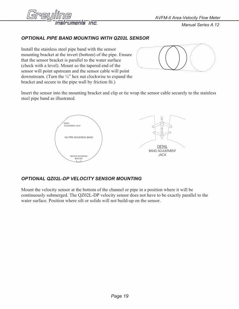
OPTIONAL PIPE BAND MOUNTING WITH QZ02L SENSOR
Install the stainless steel pipe band with the sensormounting bracket at the invert (bottom) of the pipe. Ensurethat the sensor bracket is parallel to the water surface(check with a level). Mount so the tapered end of thesensor will point upstream and the sensor cable will pointdownstream. (Turn the ¼” hex nut clockwise to expand the bracket and secure to the pipe wall by friction fit.)
Insert the sensor into the mounting bracket and clip or tie wrap the sensor cable securely to the stainlesssteel pipe band as illustrated.
OPTIONAL QZ02L-DP VELOCITY SENSOR MOUNTING
Mount the velocity sensor at the bottom of the channel or pipe in a position where it will becontinuously submerged. The QZ02L-DP velocity sensor does not have to be exactly parallel to thewater surface. Position where silt or solids will not build-up on the sensor.
Page 19
AVFM-II Area-Velocity Flow Meter
Manual Series A.12
DETAILBAND ADJUSTMENT
JACK
VSJ PIPE MOUNTING BAND
BANDADJUSTMENT JACK
SENSOR MOUNTINGBRACKET
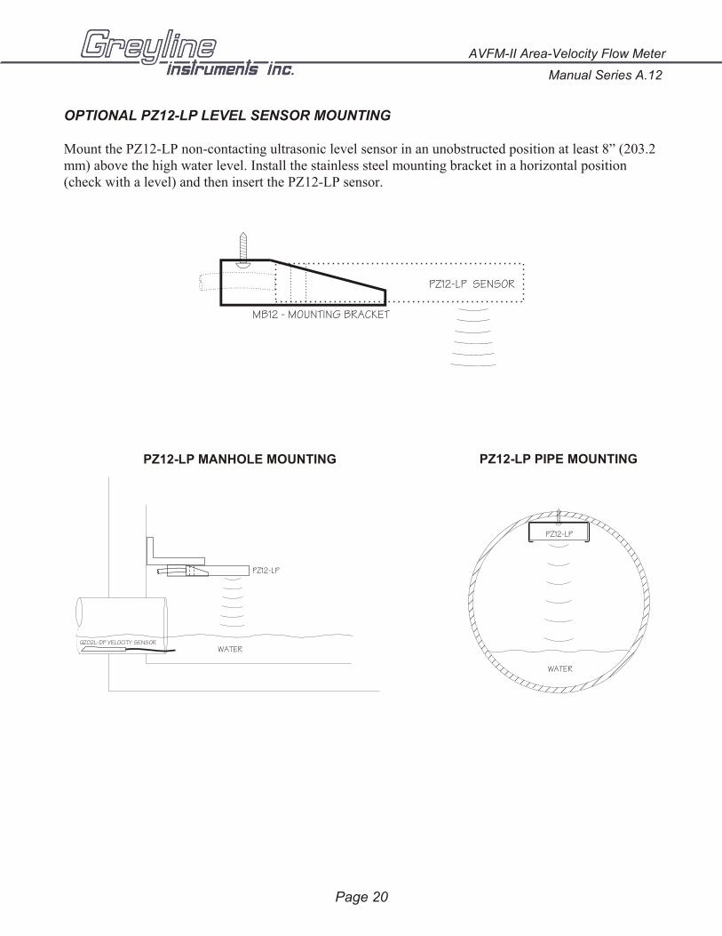
OPTIONAL PZ12-LP LEVEL SENSOR MOUNTING
Mount the PZ12-LP non-contacting ultrasonic level sensor in an unobstructed position at least 8” (203.2 mm) above the high water level. Install the stainless steel mounting bracket in a horizontal position(check with a level) and then insert the PZ12-LP sensor.
Page 20
Manual Series A.12
AVFM-II Area-Velocity Flow Meter
WATER
PZ12-LP
PZ12-LP MANHOLE MOUNTING
PZ12-LP
WATER
PZ12-LP PIPE MOUNTING
QZ02L-DP VELOCITY SENSOR
PZ12-LP SENSOR
MB12 - MOUNTING BRACKET
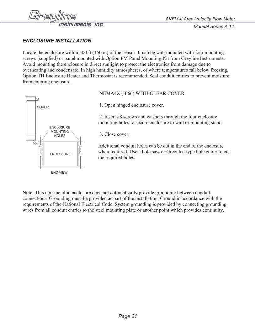
ENCLOSURE INSTALLATION
Locate the enclosure within 500 ft (150 m) of the sensor. It can be wall mounted with four mountingscrews (supplied) or panel mounted with Option PM Panel Mounting Kit from Greyline Instruments.Avoid mounting the enclosure in direct sunlight to protect the electronics from damage due tooverheating and condensate. In high humidity atmospheres, or where temperatures fall below freezing,Option TH Enclosure Heater and Thermostat is recommended. Seal conduit entries to prevent moisturefrom entering enclosure.
NEMA4X (IP66) WITH CLEAR COVER
1. Open hinged enclosure cover.
2. Insert #8 screws and washers through the four enclosuremounting holes to secure enclosure to wall or mounting stand.
3. Close cover.
Additional conduit holes can be cut in the end of the enclosurewhen required. Use a hole saw or Greenlee-type hole cutter to cutthe required holes.
Note: This non-metallic enclosure does not automatically provide grounding between conduitconnections. Grounding must be provided as part of the installation. Ground in accordance with therequirements of the National Electrical Code. System grounding is provided by connecting groundingwires from all conduit entries to the steel mounting plate or another point which provides continuity.
AVFM-II Area-Velocity Flow Meter
Manual Series A.12
Page 21
END VIEW
COVER
ENCLOSURE
ENCLOSURE
MOUNTINGHOLES
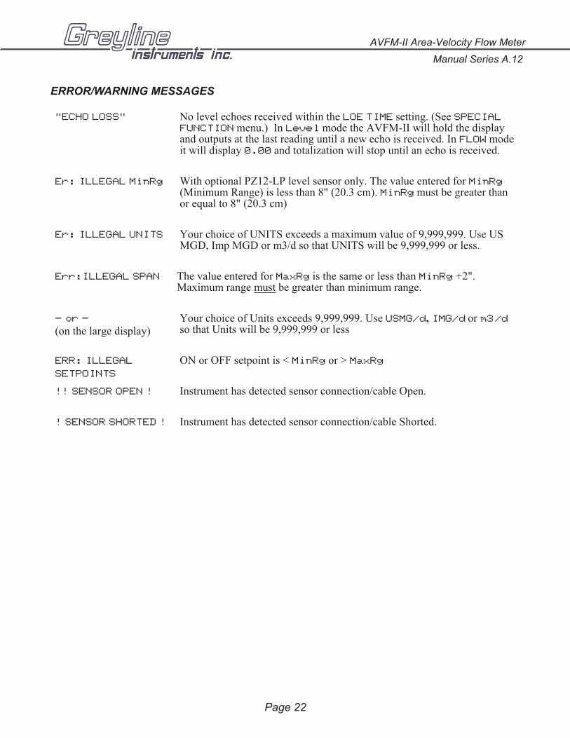
ERROR/WARNING MESSAGES
"ECHO LOSS" No level echoes received within the LOE TIME setting. (See SPECIALFUNCTION menu.) In Level mode the AVFM-II will hold the displayand outputs at the last reading until a new echo is received. In FLOW mode it will display 0.00 and totalization will stop until an echo is received.
Er: ILLEGAL MinRg With optional PZ12-LP level sensor only. The value entered for MinRg(Minimum Range) is less than 8" (20.3 cm). MinRg must be greater thanor equal to 8" (20.3 cm)
Er: ILLEGAL UNITS Your choice of UNITS exceeds a maximum value of 9,999,999. Use USMGD, Imp MGD or m3/d so that UNITS will be 9,999,999 or less.
Err:ILLEGAL SPAN The value entered for MaxRg is the same or less than MinRg +2".Maximum range must be greater than minimum range.
- or -
(on the large display)Your choice of Units exceeds 9,999,999. Use USMG/d, IMG/d or m3/dso that Units will be 9,999,999 or less
ERR: ILLEGAL
SETPOINTS
ON or OFF setpoint is < MinRg or > MaxRg
!! SENSOR OPEN ! Instrument has detected sensor connection/cable Open.
! SENSOR SHORTED ! Instrument has detected sensor connection/cable Shorted.
Page 22
Manual Series A.12
AVFM-II Area-Velocity Flow Meter
FIELD TROUBLESHOOTING
The AVFM-II uses an ultrasonic level sensor to determine channel AREA and an ultrasonic Dopplersensor to measure flow VELOCITY.
The QZ02L transducer combines both sensors in one housing.
An optional configuration uses the PZ12-LP “down-looking” level sensor and a QZ02L-DP velocitysensor.
To troubleshoot the AVFM-II, verify correct operation of LEVEL and VELOCITY measurementsseparately.
Note: Selecting “Defaults” in the SPECIAL FUNCTION menu will return the instrument to“as-shipped” factory settings.
LEVEL (QZ02L SENSOR)
SYMPTOMS FAULTS SOLUTIONS
EC bar graph at zero - very turbulent flow - Increase LOE time (SPECIALFUNCTION)
- very aerated flow - relocate sensor or use PZ12-LP
- sensor not level - level sensor with “Bullseye”level
- sediment/dirt/grease build-up onsensor
- clean sensor
- Level display reads 1.0inches
- Level less than 1.0 inches
VELOCITY (QZ02L SENSOR)
SYMPTOMS FAULTS SOLUTIONS
- No velocity reading - Grease/sediment on sensor- Improper hook-up
- Clean sensor with detergent- Check sensor connections
AVFM-II Area-Velocity Flow Meter
Manual Series A.12
Page 23
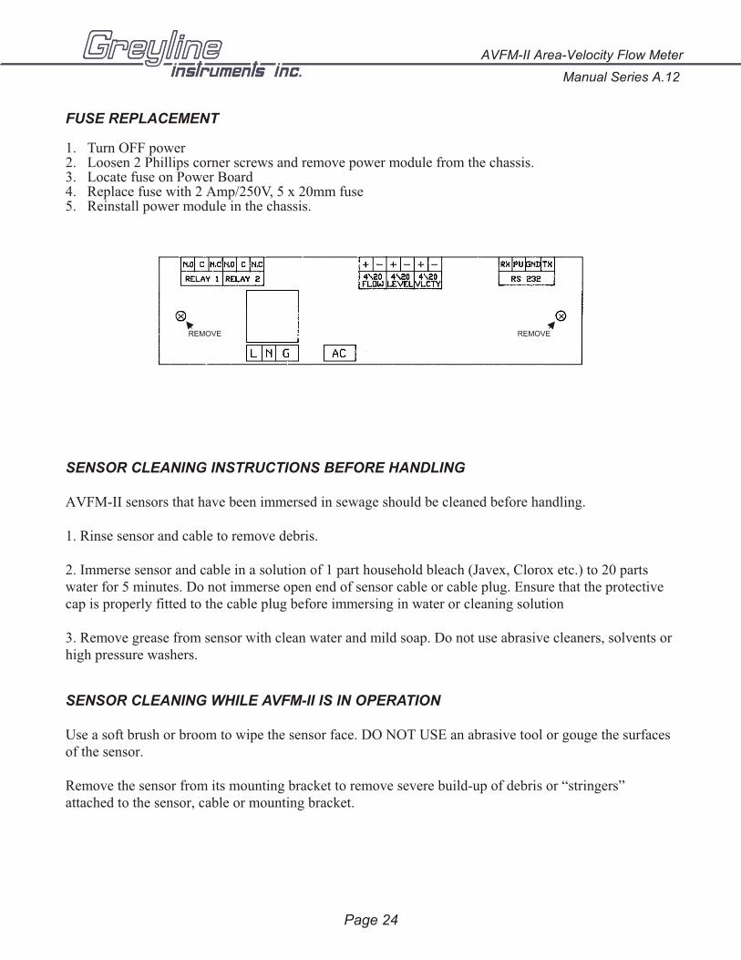
FUSE REPLACEMENT
1. Turn OFF power 2. Loosen 2 Phillips corner screws and remove power module from the chassis. 3. Locate fuse on Power Board4. Replace fuse with 2 Amp/250V, 5 x 20mm fuse5. Reinstall power module in the chassis.
SENSOR CLEANING INSTRUCTIONS BEFORE HANDLING
AVFM-II sensors that have been immersed in sewage should be cleaned before handling.
1. Rinse sensor and cable to remove debris.
2. Immerse sensor and cable in a solution of 1 part household bleach (Javex, Clorox etc.) to 20 partswater for 5 minutes. Do not immerse open end of sensor cable or cable plug. Ensure that the protectivecap is properly fitted to the cable plug before immersing in water or cleaning solution
3. Remove grease from sensor with clean water and mild soap. Do not use abrasive cleaners, solvents orhigh pressure washers.
SENSOR CLEANING WHILE AVFM-II IS IN OPERATION
Use a soft brush or broom to wipe the sensor face. DO NOT USE an abrasive tool or gouge the surfacesof the sensor.
Remove the sensor from its mounting bracket to remove severe build-up of debris or “stringers”attached to the sensor, cable or mounting bracket.
Page 24
Manual Series A.12
AVFM-II Area-Velocity Flow Meter
REMOVE REMOVE
APPLICATIONS HOTLINE
For applications assistance, advice or information on any Greyline Instrument contact your SalesRepresentative, write to Greyline or phone the Applications Hotline below:
United States: Tel: 315-788-9500 Fax: 315-764-0419
Canada: Tel: 613-938-8956 Fax: 613-938-4857
Toll Free: 888-473-9546
Email: [email protected]
Web Site: http://www.greyline.com
Greyline Instruments Inc.
Canada USA:
16456 Sixsmith Drive 105 Water Street
Long Sault, Ont. K0C 1P0 Massena, NY 13662
Page 25
AVFM-II Area-Velocity Flow Meter
Manual Series A.12

PRODUCT RETURN PROCEDUREInstruments may be returned to Greyline for service or warranty repair.
1 Obtain an RMA Number from Greyline -Before shipping a product to the factory please contact Greyline by telephone, fax or email to obtainan RMA number (Returned Merchandise Authorization). This ensures fast service and correctbilling or credit.
When you contact Greyline please have the following information available:
1. Model number / Software Version
2. Serial number
3. Date of Purchase
4. Reason for return (description of fault or modification required)
5. Your name, company name, address and phone number
2 Clean the Sensor/Product -Important: unclean products will not be serviced and will be returned to the sender at their expense.
1. Rinse sensor and cable to remove debris.
2. If the sensor has been exposed to sewage, immerse both sensor and cable in a solution of 1 parthousehold bleach (Javex, Clorox etc.) to 20 parts water for 5 minutes. Important: do not immerse openend of sensor cable.
3. Dry with paper towels and pack sensor and cable in a sealed plastic bag.
4. Wipe the outside of the enclosure to remove dirt or deposits.
5. Return to Greyline for service.
3 Ship to Greyline -After obtaining an RMA number please ship the product to the appropriate address below:
Canadian and International USACustomers: Customers:
Greyline Instruments Inc. Greyline Instruments Inc.16456 Sixsmith Drive 204 150th Avenue
Long Sault, Ont. K0C 1P0 Madeira Beach, FL 33708
RMA# RMA#
Page 26
Manual Series A.12
AVFM-II Area-Velocity Flow Meter
Page 27
AVFM-II Area-Velocity Flow Meter
Manual Series A.12
LIMITED WARRANTY______________________
Greyline Instruments warrants, to the original purchaser, itsproducts to be free from defects in material and workmanship for a period of one year from date of invoice. Greyline will replaceor repair, free of charge, any Greyline product if it has beenproven to be defective within the warranty period. This warranty does not cover any expenses incurred in the removal andre-installation of the product.
If a product manufactured by Greyline should prove defectivewithin the first year, return it freight prepaid to GreylineInstruments along with a copy of your invoice.
This warranty does not cover damages due to improperinstallation or handling, acts of nature, or unauthorized service.Modifications to or tampering with any part shall void thiswarranty. This warranty does not cover any equipment used inconnection with the product or consequential damages due to adefect in the product.
All implied warranties are limited to the duration of thiswarranty. This is the complete warranty by Greyline and noother warranty is valid against Greyline. Some states do notallow limitations on how long an implied warranty lasts orlimitation of incidental or consequential damages, so the abovelimitations or exclusions may not apply to you.
This warranty gives you specific legal rights, and you may alsohave other rights which vary from state to state.
Greyline Instruments Inc.
APPENDIX A - OPTIONS
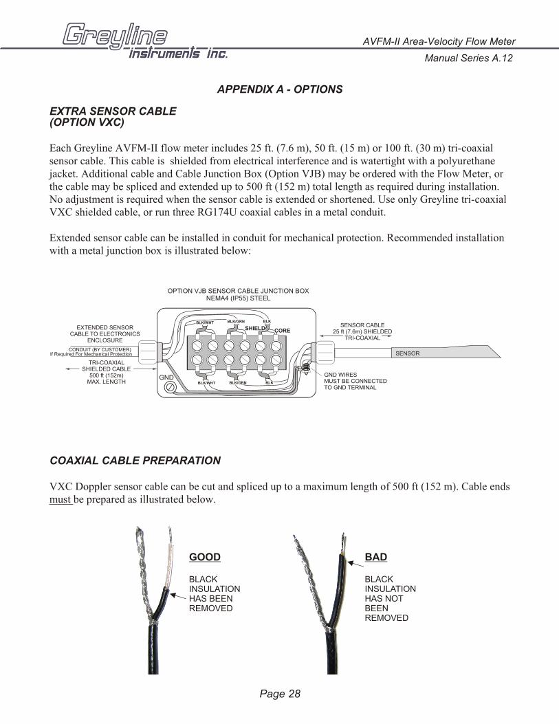
EXTRA SENSOR CABLE(OPTION VXC)
Each Greyline AVFM-II flow meter includes 25 ft. (7.6 m), 50 ft. (15 m) or 100 ft. (30 m) tri-coaxialsensor cable. This cable is shielded from electrical interference and is watertight with a polyurethanejacket. Additional cable and Cable Junction Box (Option VJB) may be ordered with the Flow Meter, orthe cable may be spliced and extended up to 500 ft (152 m) total length as required during installation.No adjustment is required when the sensor cable is extended or shortened. Use only Greyline tri-coaxialVXC shielded cable, or run three RG174U coaxial cables in a metal conduit.
Extended sensor cable can be installed in conduit for mechanical protection. Recommended installationwith a metal junction box is illustrated below:
COAXIAL CABLE PREPARATION
VXC Doppler sensor cable can be cut and spliced up to a maximum length of 500 ft (152 m). Cable ends must be prepared as illustrated below.
Manual Series A.12
AVFM-II Area-Velocity Flow Meter
Page 28
OPTION VJB SENSOR CABLE JUNCTION BOXNEMA4 (IP55) STEEL
GND
CONDUIT (BY CUSTOMER) If Required For Mechanical Protection
TRI-COAXIAL SHIELDED CABLE
500 ft (152m) MAX. LENGTH
EXTENDED SENSORCABLE TO ELECTRONICS
ENCLOSURE
SHIELD CORESENSOR CABLE
25 ft (7.6m) SHIELDEDTRI-COAXIAL
GND WIRESMUST BE CONNECTEDTO GND TERMINAL
SENSOR
BLK/WHT
BLK/WHT BLK/GRN BLK
BLK/GRN BLK
GOOD
BLACK INSULATION HAS BEEN REMOVED
BAD
BLACK INSULATION HAS NOT BEEN REMOVED
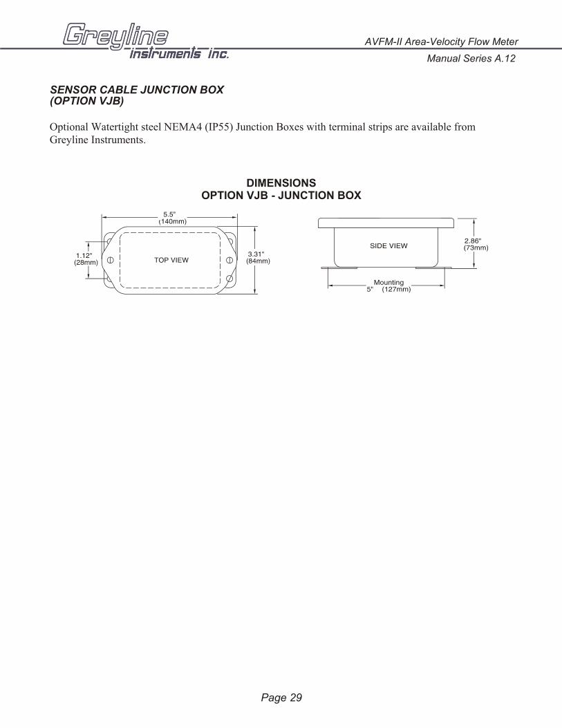
SENSOR CABLE JUNCTION BOX(OPTION VJB)
Optional Watertight steel NEMA4 (IP55) Junction Boxes with terminal strips are available fromGreyline Instruments.
AVFM-II Area-Velocity Flow Meter
Manual Series A.12
Page 29
DIMENSIONSOPTION VJB - JUNCTION BOX

SS PIPE MOUNTING BAND - OPTION VSJ
Manual Series A.12
AVFM-II Area-Velocity Flow Meter
Page 30
CODE BAND SIZE
VSJ6 6”/150 mm ID pipes
VSJ8 8”/200 mm ID pipes
VSJ10 10”/250 mm ID pipes
VSJ12 12”/300 mm ID pipes
VSJ14 14”/350 mm ID pipes
VSJ15 15”/375 mm ID pipes
VSJ16 16”/400 mm ID pipes
VSJ18 18”/450 mm ID pipes
VSJ20 20”/500 mm ID pipes
VSJ24 24”/600 mm ID pipes
VSJ30 30”/750 mm ID pipes
VSJ32-40 32-40” / 800-1000 mm ID pipesVSJ42-54 42-54” / 1100-1375 mm ID pipes
VSJ56-72 56-72” / 1400-1800 mm ID pipes
DETAILBAND ADJUSTMENT
JACK
Use optional VSJ stainless steel Pipe Mounting Bands for easy Sensor installation in round pipes.
Each Pipe Band includes:
! Band Adjustment Jack allowing ±0.5” (13 mm) adjustment from the nominal band size
! Stainless steel bracket for Sensor mounting! Pre-drilled for tie wraps (included) to secure Sensor cable
VSJ PIPE MOUNTING BAND
BANDADJUSTMENT JACK
SENSOR MOUNTINGBRACKET
Mounting Instructions:
Install the stainless steel pipe band with the sensor mounting bracket at the invert (bottom) of the pipe. Ensure that the sensor bracket is parallel to the water surface (check with a level). Mount so the tapered end of the sensor will point upstream and the sensor cable will point downstream. Turn the ¼” hex nut clockwise to expand the bracket and secure to the pipe wall by friction fit.
Insert the sensor into the mounting bracket and clip or tie wrap the sensor cable securely to the stainless steel pipe band.
FASTEN SENSORCABLE TO PIPE ORCHANNEL WITHMETAL CLIPS ORTIE WRAPS
SENSOR
END VIEW
VSJ HALF-PIPEMOUNTING BAND
ADJUSTMENTJACK
SENSOR MOUNTINGBRACKET
ENDBRACKET
FLOW
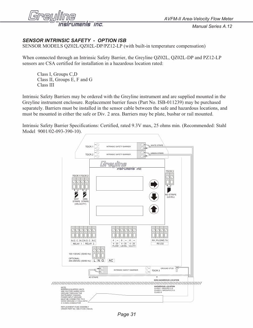
SENSOR INTRINSIC SAFETY - OPTION ISBSENSOR MODELS QZ02L/QZ02L-DP/PZ12-LP (with built-in temperature compensation)
When connected through an Intrinsic Safety Barrier, the Greyline QZ02L, QZ02L-DP and PZ12-LPsensors are CSA certified for installation in a hazardous location rated:
Class I, Groups C,DClass II, Groups E, F and GClass III
Intrinsic Safety Barriers may be ordered with the Greyline instrument and are supplied mounted in theGreyline instrument enclosure. Replacement barrier fuses (Part No. ISB-011239) may be purchasedseparately. Barriers must be installed in the sensor cable between the safe and hazardous locations, andmust be mounted in either the safe or Div. 2 area. Barriers may be plate, busbar or rail mounted.
Intrinsic Safety Barrier Specifications: Certified, rated 9.3V max, 25 ohms min. (Recommended: StahlModel 9001/02-093-390-10).
Page 31
AVFM-II Area-Velocity Flow Meter
Manual Series A.12
NOTE:BARRIER-EQUIPPED UNITSARE FACTORY-WIRED WITHGROUND THROUGH THEINSTRUMENT CHASSIS.POWER INPUT GROUNDMUST BE CONNECTED TO AGOOD GROUND (<1 Ohm) WITHA 12 AWG CONDUCTOR
REPLACEMENT FUSE ASSEMBLYORDER PART NO. ISB-011239 (160mA)
NON-HAZARDOUS LOCATION
HAZARDOUS LOCATIONCLASS I, GROUPS C,DCLASS II, GROUPS E,F,GCLASS III
33
44
11
22
INTRINSIC SAFETY BARRIER
INTRINSIC SAFETY BARRIER
INTRINSIC SAFETY BARRIER
SENSOR
TDCR.3
TDCR.1
TDCR.2
L N G AC
100-130VAC (50/60 Hz)
OPTIONAL:200-260VAC (50/60 Hz)
TDCR.3
TDCR.1 TDCR.2
*
43 1
2
WHITE STRIPE
GREEN STRIPE
NO STRIPE
WHTSTRIPE
GRNSTRIPE
(VELOCITY)
NO STRIPE(LEVEL)
GROUND STUD
N.O C N.C N.O C N.C
RELAY 1 RELAY 2
RX PU GND TX
RS 2324 - 20FLOW
4 - 20VLCTY
4 - 20LEVEL
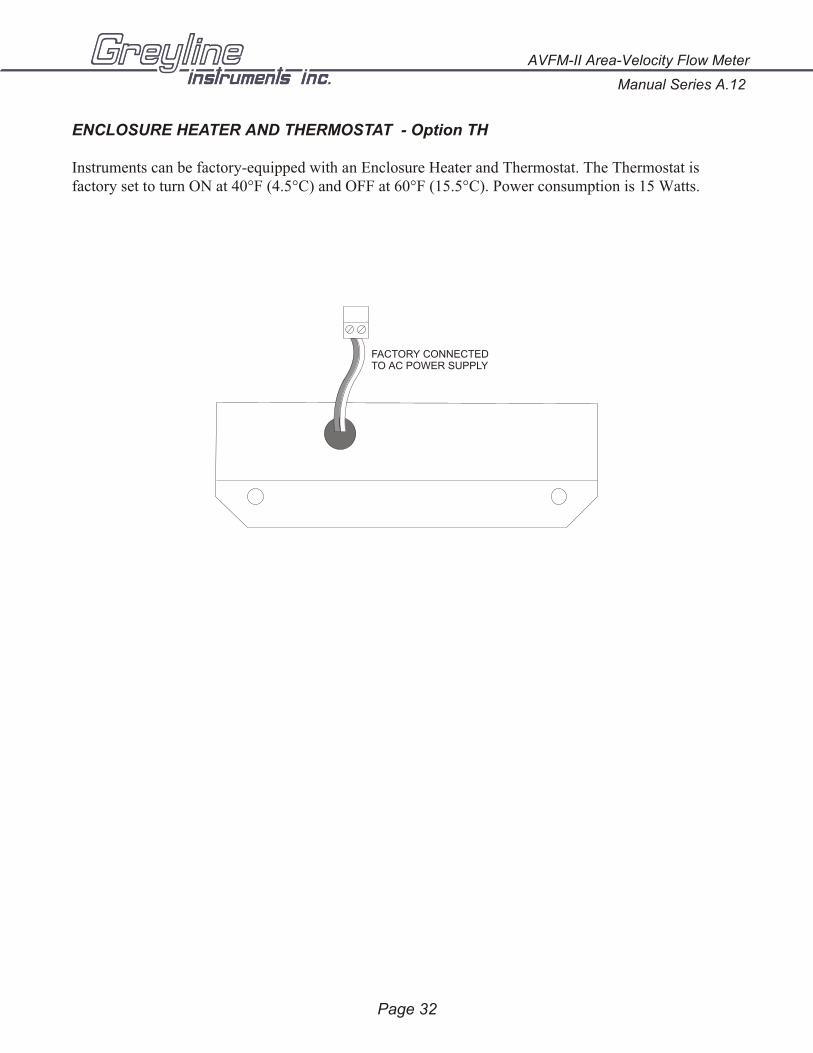
ENCLOSURE HEATER AND THERMOSTAT - Option TH
Instruments can be factory-equipped with an Enclosure Heater and Thermostat. The Thermostat isfactory set to turn ON at 40°F (4.5°C) and OFF at 60°F (15.5°C). Power consumption is 15 Watts.
Page 32
Manual Series A.12
AVFM-II Area-Velocity Flow Meter
FACTORY CONNECTEDTO AC POWER SUPPLY
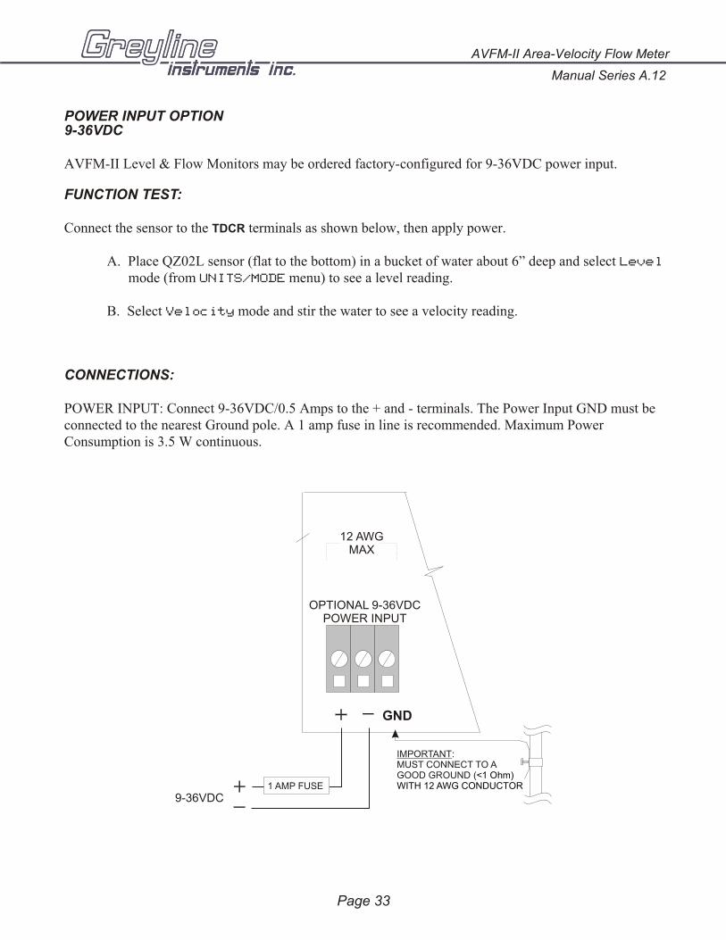
POWER INPUT OPTION9-36VDC
AVFM-II Level & Flow Monitors may be ordered factory-configured for 9-36VDC power input.
FUNCTION TEST:
Connect the sensor to the TDCR terminals as shown below, then apply power.
A. Place QZ02L sensor (flat to the bottom) in a bucket of water about 6” deep and select Level
mode (from UNITS/MODE menu) to see a level reading.
B. Select Velocity mode and stir the water to see a velocity reading.
CONNECTIONS:
POWER INPUT: Connect 9-36VDC/0.5 Amps to the + and - terminals. The Power Input GND must beconnected to the nearest Ground pole. A 1 amp fuse in line is recommended. Maximum PowerConsumption is 3.5 W continuous.
Page 33
AVFM-II Area-Velocity Flow Meter
Manual Series A.12
GND
12 AWGMAX
OPTIONAL 9-36VDCPOWER INPUT
IMPORTANT:MUST CONNECT TO AGOOD GROUND (<1 Ohm) WITH 12 AWG CONDUCTOR
9-36VDC1 AMP FUSE
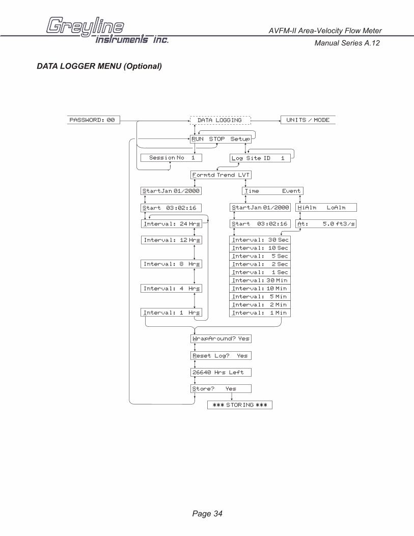
DATA LOGGER MENU (Optional)
Manual Series A.12
AVFM-II Area-Velocity Flow Meter
Page 34
DATA LOGGING
Log Site ID 1Session No 1
RUN STOP Setup
PASSWORD: 00 UNITS / MODE
StartJan 01/2000
Start 03:02:16
Interval: 24 Hrs
Interval: 12 Hrs
Interval: 1 Hrs
Time Event
HiAlm LoAlm
At: 5.0 ft3/s
StartJan 01/2000
Start 03:02:16
Interval: 8 Hrs
Interval: 4 Hrs
Interval: 30 Sec
Interval: 10 Sec
Interval: 5 Sec
Interval: 2 Sec
Interval: 1 Sec
Interval: 30 Min
Interval: 10 Min
Interval: 5 Min
Interval: 2 Min
Interval: 1 Min
*** STORING ***
Reset Log? Yes
26640 Hrs Left
Store? Yes
WrapAround? Yes
Formtd Trend LVT
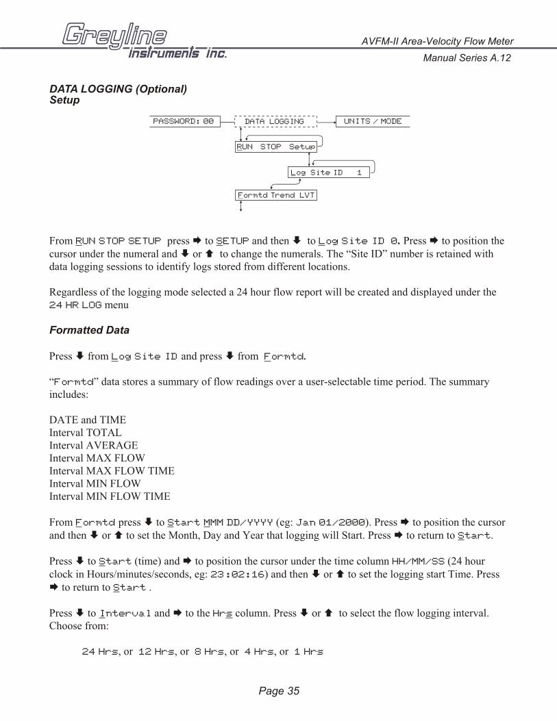
DATA LOGGING (Optional)Setup
From RUN STOP SETUP press Æ to SETUP and then È to Log Site ID 0. Press Æ to position thecursor under the numeral and È or Ç to change the numerals. The “Site ID” number is retained withdata logging sessions to identify logs stored from different locations.
Regardless of the logging mode selected a 24 hour flow report will be created and displayed under the24 HR LOG menu
Formatted Data
Press È from Log Site ID and press È from Formtd.
“Formtd” data stores a summary of flow readings over a user-selectable time period. The summaryincludes:
DATE and TIMEInterval TOTALInterval AVERAGEInterval MAX FLOWInterval MAX FLOW TIMEInterval MIN FLOWInterval MIN FLOW TIME
From Formtd press È to Start MMM DD/YYYY (eg: Jan 01/2000). Press Æ to position the cursorand then È or Ç to set the Month, Day and Year that logging will Start. Press Æ to return to Start.
Press È to Start (time) and Æ to position the cursor under the time column HH/MM/SS (24 hourclock in Hours/minutes/seconds, eg: 23:02:16) and then È or Ç to set the logging start Time. Press Æ to return to Start .
Press È to Interval and Æ to the Hrs column. Press È or Ç to select the flow logging interval.Choose from:
24 Hrs, or 12 Hrs, or 8 Hrs, or 4 Hrs, or 1 Hrs
AVFM-II Area-Velocity Flow Meter
Manual Series A.12
Page 35
DATA LOGGING
Log Site ID 1
RUN STOP Setup
PASSWORD: 00 UNITS / MODE
Formtd Trend LVT

Press Æ to return to Interval. Press È and the AVFM-II will report xxxxx Hrs Left indicatingthe amount of logging time available with your current set-up. You can also press Ç to return toprevious menu items and make changes.
Press È to WrapAround Yes?. Press Æ to Yes? and È to enable the logging wrap function. InWrapAround mode the oldest data will be overwritten by the newest. If WrapAround is not enabled thelogger will stop when its memory becomes full.
Press È to Reset Log? Yes. Press Æ to Yes and then È to reset the Log and erase all previoussessions and stored values. Or press È from Reset Log? to retain existing data in the Log. TheAVFM-II will display “xxxxx Hrs/Days Left.
From the xxxxx Hrs Left display press È to Store? Yes. Press Æ to Yes and then È to saveyour Data Logging setup, or press È from Store? to cancel changes made above and exit withoutstoring changes.
From the Data Logging Store? Yes prompt the menu will return to RUN STOP SETUP. Press Æ toposition the cursor under RUN and press È to activate the Data Logger to start at your selected startDate and Time. The AVFM-II will display SESSION NO. x. Press È to return to DATA LOGGING.
Viewing FORMATTED Data Logs on the AVFM-II Display
24 Hour Formatted logs can be viewed directly on the AVFM-II display regardless of the logging modeselected. From RUN press Æ to 24 HR LOG.
The 24 Hour Log Report is designed to be read one line at time using the Æ key. Using the È or Çkeys will return the display to the Date column.
TODAYS DATE DAILY TOTAL DAILY AVERAGE MAX FLOW MAX FLOW TIME MIN FLOW MIN FLOW TIME
PREVIOUS DATE “ “ “ “ “ “
PREVIOUS DATE “ “ “ “ “ “
PREVIOUS DATE “ “ “ “ “ “
PREVIOUS DATE “ “ “ “ “ “
PREVIOUS DATE “ “ “ “ “ “
The current day plus the past 255 days of data can be displayed. (Greyline Logger Windows softwarewill display up to 1300 days of data.)
Trend Data Logging - Setup
From RUN STOP SETUP press Æ to SETUP and then È to Log Site ID 0. Press Æ to position thecursor under the numeral and È or Ç to change the numerals. The “Site ID” number is retained withdata logging sessions to identify logs stored from different locations.
From Log Site ID press È to Formtd Trend LVT and press Æ to position the cursor underTrend. Then press È to select Time based logging.
Page 36
Manual Series A.12
AVFM-II Area-Velocity Flow Meter
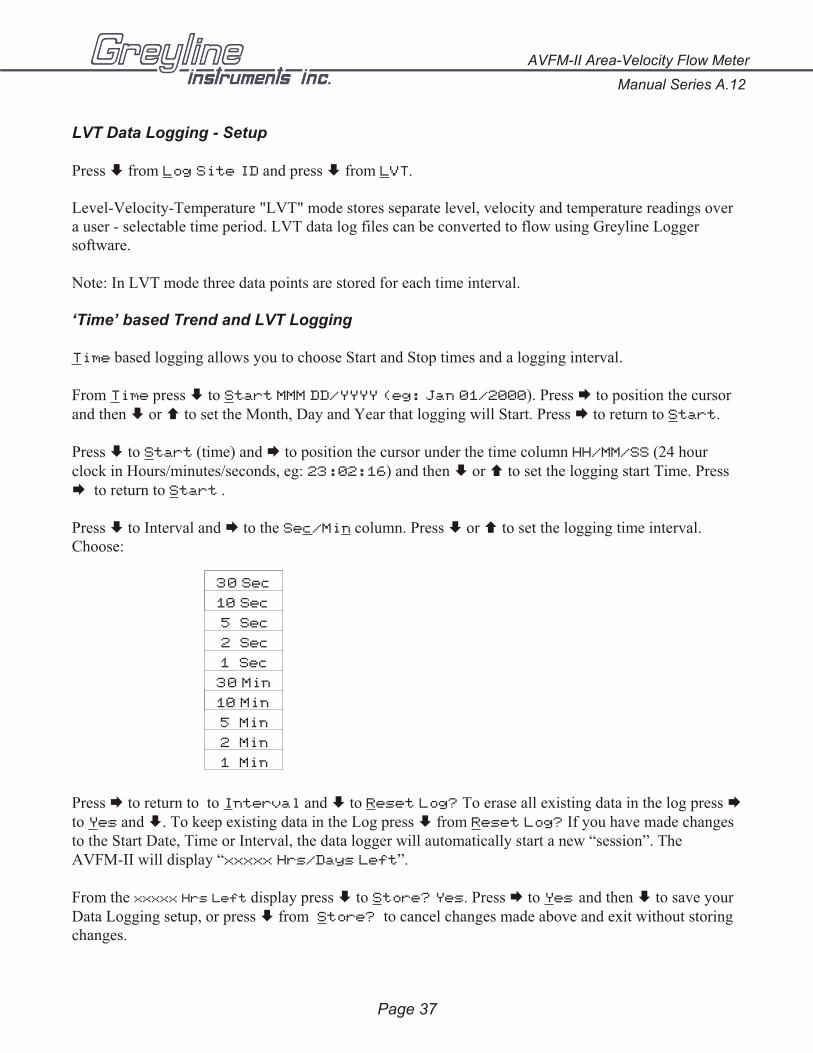
LVT Data Logging - Setup
Press È from Log Site ID and press È from LVT.
Level-Velocity-Temperature "LVT" mode stores separate level, velocity and temperature readings overa user - selectable time period. LVT data log files can be converted to flow using Greyline Loggersoftware.
Note: In LVT mode three data points are stored for each time interval.
‘Time’ based Trend and LVT Logging
Time based logging allows you to choose Start and Stop times and a logging interval.
From Time press È to Start MMM DD/YYYY (eg: Jan 01/2000). Press Æ to position the cursorand then È or Ç to set the Month, Day and Year that logging will Start. Press Æ to return to Start.
Press È to Start (time) and Æ to position the cursor under the time column HH/MM/SS (24 hourclock in Hours/minutes/seconds, eg: 23:02:16) and then È or Ç to set the logging start Time. PressÆ to return to Start .
Press È to Interval and Æ to the Sec/Min column. Press È or Ç to set the logging time interval.Choose:
30 Sec
10 Sec
5 Sec
2 Sec
1 Sec
30 Min
10 Min
5 Min
2 Min
1 Min
Press Æ to return to to Interval and È to Reset Log? To erase all existing data in the log press Æto Yes and È. To keep existing data in the Log press È from Reset Log? If you have made changesto the Start Date, Time or Interval, the data logger will automatically start a new “session”. TheAVFM-II will display “xxxxx Hrs/Days Left”.
From the xxxxx Hrs Left display press È to Store? Yes. Press Æ to Yes and then È to save yourData Logging setup, or press È from Store? to cancel changes made above and exit without storingchanges.
Page 37
AVFM-II Area-Velocity Flow Meter
Manual Series A.12

From the Data Logging Store? Yes prompt the menu will return to RUN STOP SETUP. Press Æ toposition the cursor under RUN and press È to activate the Data Logger to start at your selected startDate and Time. The AVFM-II will display SESSION NO. x. Press È to return to DATA LOGGING.
‘Event’ based Trend and LVT Logging
Event based logging stores data points only when a High or Low set point has been reached.
With cursor under Event press È to HiAlm LoAlm . HiAlm will log points above a selectable level,flow or velocity point rate, while LoAlm will log points below a selectable level, flow or velocity point.Position the cursor under HiAlm or LoAlm and press È to the At: prompt. Press Æ to the numeralscolumn and press È or Ç to set the alarm logging set point. Press Æ to return to At:
Press È to In ter val and Æ to the Sec/Min col umn. Press È or Ç to set the log ging time in ter val.
Choose:
30 Sec
10 Sec
5 Sec
2 Sec
1 Sec
30 Min
10 Min
5 Min
2 Min
1 Min
Press Æ to return to Interval and press È to WrapAround?. Press Æ to Yes to overwrite theoldest data point with each new data point stored when the logger storage capacity has been reached.
To retain all data points collected and stop logging when the logger storage capacity has been reachedpress È from WrapAround?.
From Reset Log? press Æ to erase all existing data in the log (including the on-screen 24 hr log)press Æ to Yes and È. To keep ex ist ing data in the Log press È from Re set Log? If you have madechanges to the Start Date, Time or In ter val, the data log ger will au to mat i cally start a new “ses sion”. TheAVFM-II will dis play “xxxxx Hrs/Days Left”.
From the xxxxx Hrs Left dis play press È to Store? Yes. Press Æ to Yes and then È to saveyour Data Logging setup, or press È from Store? to can cel changes made above and exit with outstor ing changes.
Manual Series A.12
AVFM-II Area-Velocity Flow Meter
Page 38
From the Data Logging Store? Yes prompt the menu will return to RUN STOP SETUP. Press Æ toposition the cursor under RUN and press È to ac ti vate the Data Log ger to start. The AVFM-II willdis play SESSION NO. x. Press È to re turn to DATA LOGGING.
Note: Greyline Logger software cannot accurately calculate totals from 'event' based log files. Use'trend' logging format if totals must be calculated.
Logging "Sessions"
Each time you select STOP in the DATA LOGGING menu, the Data Log ger stores the cur rent data inmem ory as a "SESSION NO" au to mat i cally num bered from "1" to "10". If you re sume log ging byse lect ing RUN, the Data Log ger will re port that a new log ging ses sion is started and ti tled "SESSION
NO xx". When you down load the log ger files to your PC us ing Greyline Log ger soft ware, each Ses sionwill open as a sep a rate graph/ta ble ti tled "Greyline Data Log xx".
Important:If you STORE instrument calibration changes under the UNITS/MODE or CALIBRATION menus,STOP the data logger and select RUN again to start a new logging Session with your new calibrationvalues.
AVFM-II Area-Velocity Flow Meter
Manual Series A.12
Page 39
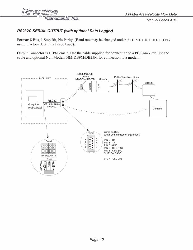
RS232C SERIAL OUTPUT (with optional Data Logger)
Format: 8 Bits, 1 Stop Bit, No Parity. (Baud rate may be changed under the SPECIAL FUNCTIONS
menu. Factory default is 19200 baud).
Output Connector is DB9-Female. Use the cable supplied for connection to a PC Computer. Use thecable and optional Null Modem NM-DB9M/DB25M for connection to a modem.
Page 40
Manual Series A.12
AVFM-II Area-Velocity Flow Meter
GreylineInstrument
RS23220' (6 m) cable
included
Detail
INCLUDED
RX
RS 232
PU GND TX
(GR
EE
N)
(WH
T)
(BL
K)
(RE
D)
Wired as DCE(Data Communication Equipment)
PIN 2 - RXPIN 3 - TXPIN 5 - GND
SHIELD - CASE
(PU = PULL-UP)
PIN 6 - DSR (PU)PIN 8 - CTS (PU)
54321
9876
Detail
DB
9F
DB
25F
Modem
Modem
Computer
DB
9M
DB
25M
Public Telephone Lines
NULL MODEMOption
NM-DB9M/DB25M

ENCLOSURE SUNSCREEN - OPTION SCR
Do not mount instrument electronics in direct sunlight. Overheating will reduce the life of electroniccomponents and condensate may form during the heat/cool cycles and cause electrical shorts.
AVFM-II Area-Velocity Flow Meter
Manual Series A.12
Page 41
Note:
Exposure to direct sunlight can causeoverheating and moisture condensationwhich will reduce the operating life ofelectronics.
Protect Instruments from direct sunlightwith this iridite finished aluminum sunscreen (Greyline Option SCR).
Seal conduit entries with caulkingcompound to further reduce moisturecondensation.
11" / 280 mm
5"127 mm
11"280 mm
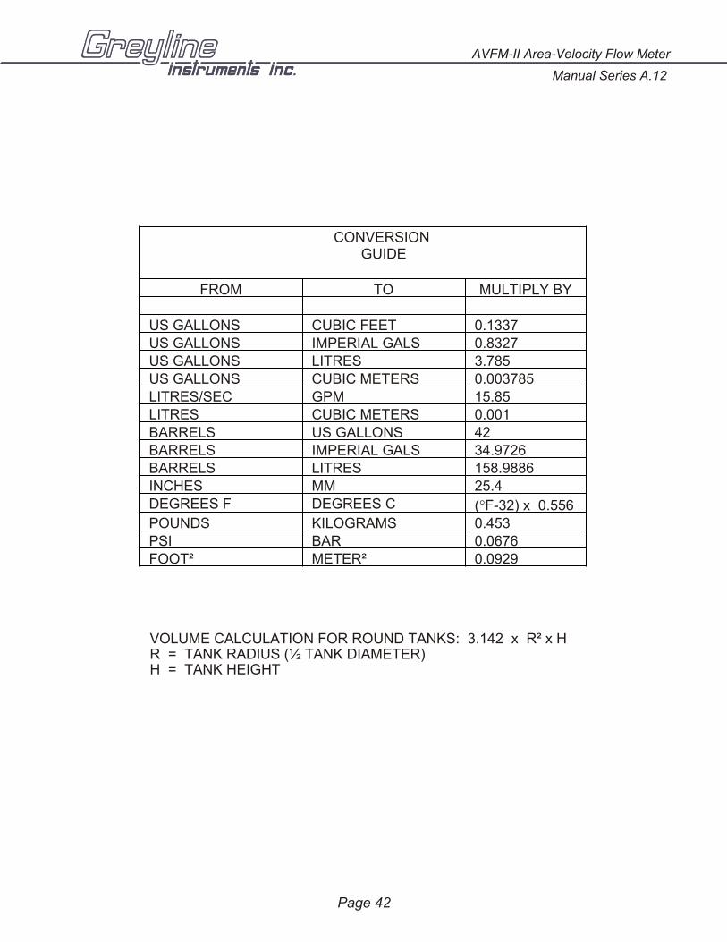
VOLUME CALCULATION FOR ROUND TANKS: 3.142 x R² x HR = TANK RADIUS (½ TANK DIAMETER)H = TANK HEIGHT
Page 42
Manual Series A.12
AVFM-II Area-Velocity Flow Meter
CONVERSION GUIDE
FROM TO MULTIPLY BY
US GALLONS CUBIC FEET 0.1337
US GALLONS IMPERIAL GALS 0.8327
US GALLONS LITRES 3.785
US GALLONS CUBIC METERS 0.003785
LITRES/SEC GPM 15.85
LITRES CUBIC METERS 0.001
BARRELS US GALLONS 42
BARRELS IMPERIAL GALS 34.9726
BARRELS LITRES 158.9886
INCHES MM 25.4
DEGREES F DEGREES C (°F-32) x 0.556
POUNDS KILOGRAMS 0.453
PSI BAR 0.0676
FOOT² METER² 0.0929
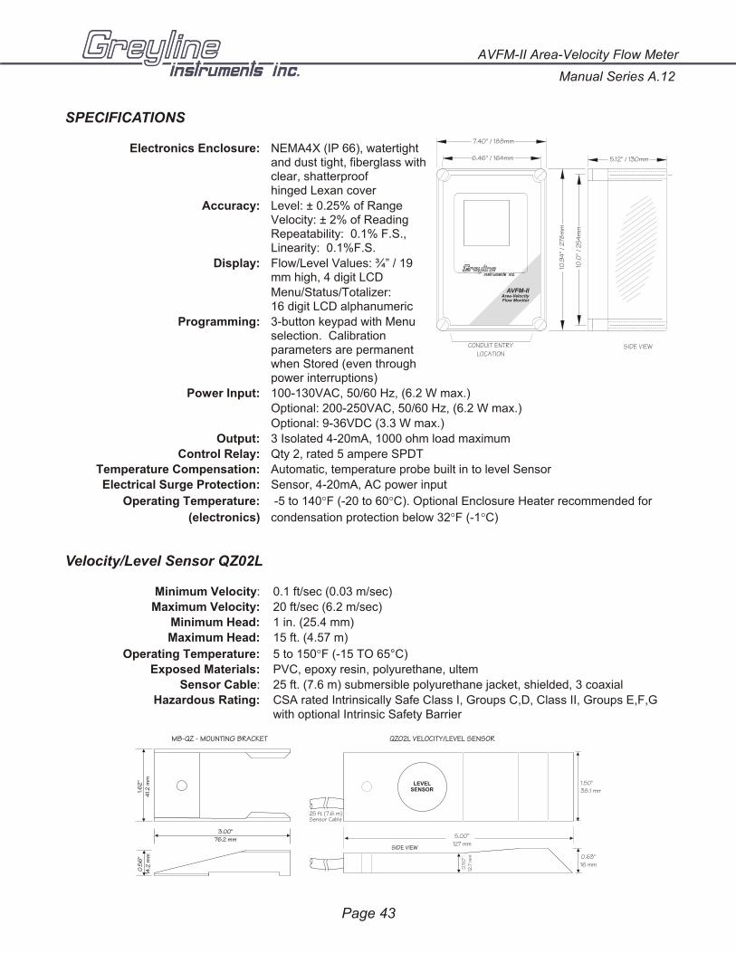
SPECIFICATIONS
Electronics Enclosure: NEMA4X (IP 66), watertightand dust tight, fiberglass with clear, shatterproofhinged Lexan cover
Accuracy: Level: ± 0.25% of RangeVelocity: ± 2% of ReadingRepeatability: 0.1% F.S.,Linearity: 0.1%F.S.
Display: Flow/Level Values: ¾” / 19mm high, 4 digit LCD
Menu/Status/Totalizer: 16 digit LCD alphanumeric
Programming: 3-button keypad with Menu selection. Calibration parameters are permanent when Stored (even through power interruptions)
Power Input: 100-130VAC, 50/60 Hz, (6.2 W max.)
Optional: 200-250VAC, 50/60 Hz, (6.2 W max.)
Optional: 9-36VDC (3.3 W max.)
Output: 3 Isolated 4-20mA, 1000 ohm load maximum
Control Relay: Qty 2, rated 5 ampere SPDT
Temperature Compensation: Automatic, temperature probe built in to level Sensor
Electrical Surge Protection: Sensor, 4-20mA, AC power input
Operating Temperature: -5 to 140°F (-20 to 60°C). Optional Enclosure Heater recommended for
(electronics) condensation protection below 32°F (-1°C)
Velocity/Level Sensor QZ02L
Minimum Velocity: 0.1 ft/sec (0.03 m/sec)
Maximum Velocity: 20 ft/sec (6.2 m/sec)
Minimum Head: 1 in. (25.4 mm)
Maximum Head: 15 ft. (4.57 m)
Operating Temperature: 5 to 150°F (-15 TO 65°C)
Exposed Materials: PVC, epoxy resin, polyurethane, ultem
Sensor Cable: 25 ft. (7.6 m) submersible polyurethane jacket, shielded, 3 coaxial
Hazardous Rating: CSA rated Intrinsically Safe Class I, Groups C,D, Class II, Groups E,F,G with optional Intrinsic Safety Barrier
AVFM-II Area-Velocity Flow Meter
Manual Series A.12
Page 43
SIDE VIEW
10.9
4"
/ 2
78m
m
10.0
" /
25
4m
m
7.40" / 188mm
6.46" / 164mm 5.12" / 130mm
CONDUIT ENTRYLOCATION
AVFM-IIArea-VelocityFlow Monitor
1.62
"4
1.2 m
m0
.56
"14
.2 m
m
3.00"76.2 mm
MB-QZ - MOUNTING BRACKET QZ02L VELOCITY/LEVEL SENSOR
25 ft (7.6 m)Sensor Cable
5.00”127 mm
1.5038.1 mm
"
0.63"16 mm
SIDE VIEW
0.5
0"
12.7
mm
LEVELSENSOR
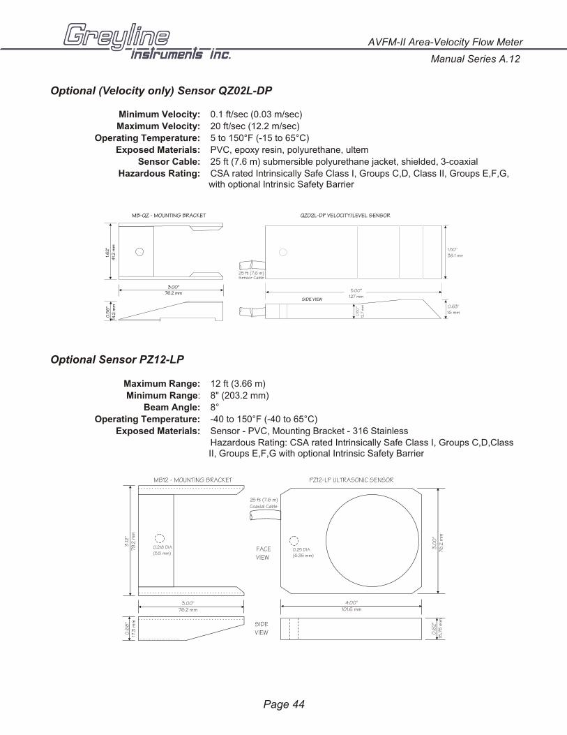
Optional (Velocity only) Sensor QZ02L-DP
Minimum Velocity: 0.1 ft/sec (0.03 m/sec)
Maximum Velocity: 20 ft/sec (12.2 m/sec)
Operating Temperature: 5 to 150°F (-15 to 65°C)
Exposed Materials: PVC, epoxy resin, polyurethane, ultem
Sensor Cable: 25 ft (7.6 m) submersible polyurethane jacket, shielded, 3-coaxial
Hazardous Rating: CSA rated Intrinsically Safe Class I, Groups C,D, Class II, Groups E,F,G,with optional Intrinsic Safety Barrier
Optional Sensor PZ12-LP
Maximum Range: 12 ft (3.66 m)
Minimum Range: 8" (203.2 mm)
Beam Angle: 8°
Operating Temperature: -40 to 150°F (-40 to 65°C)
Exposed Materials: Sensor - PVC, Mounting Bracket - 316 Stainless
Hazardous Rating: CSA rated Intrinsically Safe Class I, Groups C,D,ClassII, Groups E,F,G with optional Intrinsic Safety Barrier
Manual Series A.12
AVFM-II Area-Velocity Flow Meter
Page 44
QZ02L-DP VELOCITY/LEVEL SENSOR
25 ft (7.6 m)Sensor Cable
5.00”127 mm
1.5038.1 mm
"
0.63"16 mm
SIDE VIEW
0.5
0"
12.7
mm
1.62
"4
1.2 m
m0
.56
"14
.2 m
m
3.00"76.2 mm
MB-QZ - MOUNTING BRACKET
4.00"101.6 mm
3.0
0"
76.2
mm
0.6
2"
15.7
5 m
m
FACEVIEW
SIDEVIEW
0.25 DIA(6.35 mm)
MB12 - MOUNTING BRACKET PZ12-LP ULTRASONIC SENSOR
0.218 DIA(5.5 mm)
3.00"76.2 mm
0.6
8"
17.3
mm
3.12
"79
.2 m
m
25 ft (7.6 m)Coaxial Cable

PA
SS
WO
RD
: 0
0
OP
TIO
NA
L F
EA
TU
RE
S
RU
N
2
4 H
R R
EP
OR
T
J
an
0
1/
20
00
-
>
D
ai
ly
TO
TA
L
D
ai
ly
AV
ER
AG
E
D
ai
ly
MA
X F
lo
w
M
AX
Fl
ow
TI
ME
D
ai
ly
MI
N F
lo
w
M
IN
Fl
ow
TI
ME
D
ec
31
/1
99
9 -
>
2
55
Da
ys
- n
o m
or
e d
at
a -
AV
FM
-II -
CA
LIB
RA
TIO
N R
EC
OR
D
Ve
lo
ci
ty
:0
.0
0f
t/
s
Le
ve
l:
0
.0
00
ft
CA
LI
BR
AT
IO
N
D
AT
A L
OG
GI
NG
Lo
g S
it
e I
D 1
Se
ss
io
n N
o 1 F
or
mt
d T
re
nd
L
VT
RU
N
ST
OP
S
et
up
St
ar
tJ
an
01
/2
00
0
St
ar
t 0
3:
02
:1
6
In
te
rv
al
: 2
4 H
rs
In
te
rv
al
: 1
2 H
rs
In
te
rv
al
:
1 H
rs
Ti
me
E
ve
nt H
iA
lm
L
oA
lm
At
:
5
.0
ft
3/
s
St
ar
tJ
an
01
/2
00
0
St
ar
t
0
3:
02
:1
6
In
te
rv
al
: 8
H
rs
In
te
rv
al
: 4
H
rs
In
te
rv
al
: 3
0 S
ec
In
te
rv
al
: 1
0 S
ec
In
te
rv
al
: 5
Se
c
In
te
rv
al
: 2
Se
c
In
te
rv
al
: 1
Se
c
In
te
rv
al
: 3
0 M
in
In
te
rv
al
: 1
0 M
in
In
te
rv
al
: 5
Mi
n
In
te
rv
al
: 2
Mi
n
In
te
rv
al
: 1
Mi
n
**
* S
TO
RI
NG
**
*
Re
se
t L
og
? Y
es
26
64
0 H
rs
L
ef
t
St
or
e?
Y
es
St
or
e?
Ye
s
CH
AN
NE
L S
ET
UP
Ro
un
d
Wi
dt
hW
id
th
U
NI
TS
/M
OD
E
ft
i
n
m
cm
Ra
ng
e
St
or
e?
Ye
s
ft
3 U
SG
U
SM
GI
G I
MG
m
3 L
s m
in
h
r d
Ch
an
ID
Sq
ua
re
Le
ve
l F
lo
w V
el
oc
it
y
Tr
ap
ez
d
Sl
op
e
Eg
g
He
ig
ht
Mi
nR
g
1
.3
33
ft
Ma
xR
g
32
.0
0 f
t
Da
mp
in
g
2
0
%
St
or
e?
Ye
s
Ma
xL
vl
3
.0
00
ft
Ma
xV
1
0.
00
ft
/s
Ma
xF
10
.0
00
ft
3/
s
Mi
nL
vl
0
.1
25
ft
Re
la
ys
:1
2
To
t:
SC
v
EC
SP
EC
IA
L F
UN
CT
IO
N
AV
FM
II
V 2
.7
8
RE
LA
Y P
AR
AM
ET
ER
S
Pu
ls
e
R1
on
0.
00
f
t3
Fl
ow
R1
on
0.
00
ft
3/
s
R1
OF
F 0
.0
0 f
t3
/s
R1
L
OE
O
ff
On
St
or
e?
Y
es
Ho
ld
Ta
g
0
1
Da
te
Ma
y 3
1/
19
99
Ti
me
23
:3
9:
51
Vi
ew
Co
de
s?
Ye
s
LO
E T
im
e
3
0 s
Re
se
t
T
ot
?
Ye
s
Te
mp
20
.3
Cº
Mi
n T
em
p
2
0.
0Cº
Ma
x T
em
p
2
3.
0Cº
DI
SP
LA
Y
C
Fº
º
Ca
l C
on
st
Ve
lo
ci
ty
Le
ve
l
Fl
ow
Ve
lo
ci
ty
R1
on
0
.0
0 f
t
R1
OF
F
0.
00
ft
Pu
ls
e
R2
on
0.
00
f
t3
R2
on
0.
00
ft
3/
s
R2
OF
F 0
.0
0 f
t3
/s
R2
L
OE
O
ff
On
Ho
ld
Le
ve
l
R2
on
0
.0
0 f
t
R2
OF
F
0.
00
ft
De
fa
ul
ts
?
Ye
s
Si
mu
l
0.
00
%
Ne
w P
as
sw
or
d:
00
Co
m
96
19
2
St
or
e?
Y
es
R1
F
un
ct
io
n
Of
f
R2
F
un
ct
io
n
Of
f
IS
B?
: N
o
Ye
s
Wr
ap
Ar
ou
nd
? Y
es
Lv
lO
FF
SE
T
Se
ria
l # _
__
__
__
__
__
__
__
__
__
__
__
Da
te: _
__
__
__
__
__
__
__
__
__
__
__
__


