17 February 2015Basic Sanitary Wastewater TreatmentWater Arabia 2015
Basic Sanitary Wastewater Treatment
Nick Cooper – AECOM USA

Nick Cooper [email protected]– Vice President, Wastewater Technical Practice Leader
– Project Manager – Wastewater Treatment, Biosolids, Water Reuse, Industrial Treatment
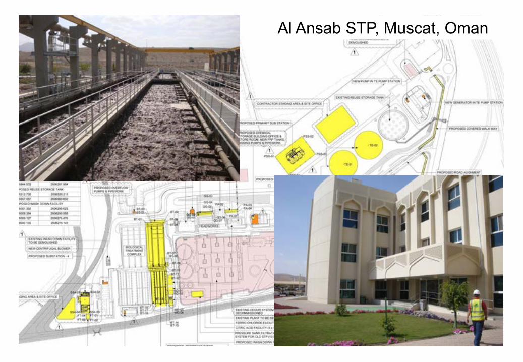
– Process Design Lead – Jebel Ali (Dubai) STP Phase 2 Expansion; Al Ansab (Oman) STP Expansion
– Experience – USA, Canada, Middle East, UK, Southeast Asia, South America
Contributing Author:Metcalf & Eddy – Water ReuseMOP 32 – Energy ConservationMOP 34 – Membrane BioreactorsMetcalf & Eddy – Wastewater
Engineering, 5th EditionBasic Sanitary Wastewater TreatmentWater Arabia 2015
March 12, 2015
Al Ansab STP, Muscat, Oman

March 12, 2015
Jebel Ali STP, Dubai UAE

Agenda
5Basic Sanitary Wastewater TreatmentWater Arabia 2015
08:30 Overview of Wastewater Treatment
09:30 Preliminary and Primary Treatment
10:00 – 10:30 Break
10:30 Biological Treatment Processes
11:30 – 13:00 Lunch Break
13:00 Clarification, Filtration and Disinfection
14:00 Odor Control and Treatment
14:30 – 15:00 Break
15:00 Sludge Handling and Treatment
15:30 – 16:00 Question Period
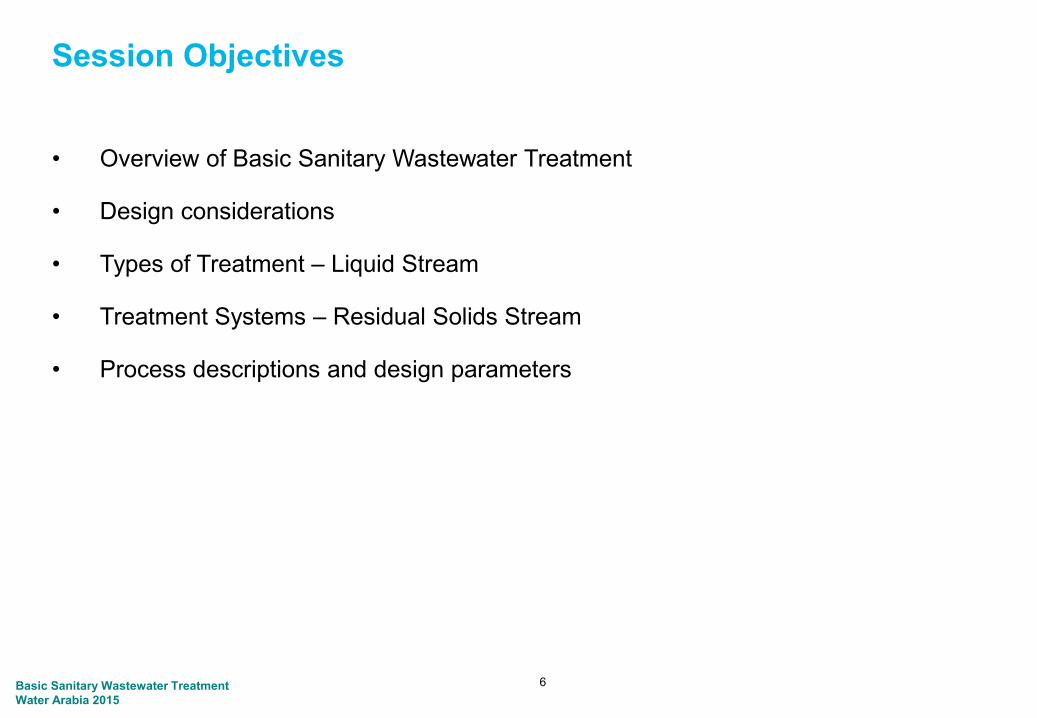
Session Objectives
• Overview of Basic Sanitary Wastewater Treatment
• Design considerations
• Types of Treatment – Liquid Stream
• Treatment Systems – Residual Solids Stream
• Process descriptions and design parameters
6Basic Sanitary Wastewater TreatmentWater Arabia 2015

References
7Basic Sanitary Wastewater TreatmentWater Arabia 2015

Basic Sanitary Wastewater TreatmentWater Arabia 2015
Overview of Wastewater Treatment

History of Wastewater Treatment
Screening
DisinfectionOxidation Ponds
ImhoffTanks
TricklingFilters
Activated Sludge1914
Rotating Biological Contactors
UV Disinfection
High Rate Activated
Sludge
Biological Nutrient Removal
1860 1870 1880 1900 1910 1920 1960 1970
Membrane Bioreactors
19901980
PL 92-500 October 1972
1890

Basic Sanitary Wastewater TreatmentWater Arabia 2015
1. Many Configurations and Processes in Wastewater Treatment

11Basic Sanitary Wastewater EngineeringWater Arabia 2013
DC WATER BLUE PLAINS WWTP, USA1400 MLD Capacity

F WAYNE HILL WRC, GEORGIA USA227 MLD Capacity
Basic Sanitary Wastewater TreatmentWater Arabia 2015

Basic Sanitary Wastewater EngineeringWater Arabia 2013
MALABAR STP, SYDNEY AUS1000 MLD Capacity

Compact Treatment
14
60 MLD Membrane Bioreactor STP
20 MLD Membrane Bioreactor STP
10 MLD Membrane Bioreactor STP
Basic Sanitary Wastewater TreatmentWater Arabia 2015

21 MLD Palm Jumeirah
WRF
Palm Jumeirah

Membrane Biological Reactors
Anoxic Tanks
Equalization Tanks Cassette Tanks
Anoxic Tanks

Where is the Treatment Plant?
17Basic Sanitary Wastewater EngineeringWater Arabia 2013

Suji STP (SAMSUNG Engineering)Yong-in City, Korea110 MLD
July 2007
February 2008

Basic Sanitary Wastewater TreatmentWater Arabia 2015
2. Terminology

Terminology– BOD – Biochemical Oxygen Demand
– COD – Chemical Oxygen Demand
– TSS – Total Suspended Solids
– Coliform - Bacteria Colony Forming Units
– DO – Dissolved Oxygen
– Screenings – Floating debris removed by screening units
– Grit – Inert debris (sand, coffee grounds, egg shells)
– FOG – Fats, Oils, Grease
– Sludge/Biosolids – Residual Waste from Biological Treatment
– TSE – Treated Sewage Effluent
– Mixed Liquor – Biomass in Activated Sludge Reactors
20Basic Sanitary Wastewater TreatmentWater Arabia 2015

Terminology, Cont’d
21
Preliminary Treatment
Primary Treatment
Secondary Treatment
Biological Treatment
Activated Sludge /Suspended Growth Processes
Fixed Film/ Attached Growth Processes
Tertiary Treatment
Nutrient Removal
Return Activated Sludge
Waste Activated Sludge
Basic Sanitary Wastewater TreatmentWater Arabia 2015

Overview of Basic Sanitary Wastewater Treatment
• Wastewater is 99.97% Pure Water
• Wastewater Treatment is a series of physical, chemical and biological processes to improve quality before reuse or disposal
• Wastewater Treatment can be to any level, even drinking water quality, with the right selection of processes
• Astronauts recycle wastewater for potable use every day
• Treatment depends on end use of the water and environmental impact
22Basic Sanitary Wastewater TreatmentWater Arabia 2015

Why treat it?• Reduce pollution in rivers• Reduce pollution in sea• Improve aesthetics• Bacteria and viruses are harmful to
people• Fish need oxygen to live• Reuse – valuable resource
Sewage
Basic Sanitary Wastewater TreatmentWater Arabia 2015
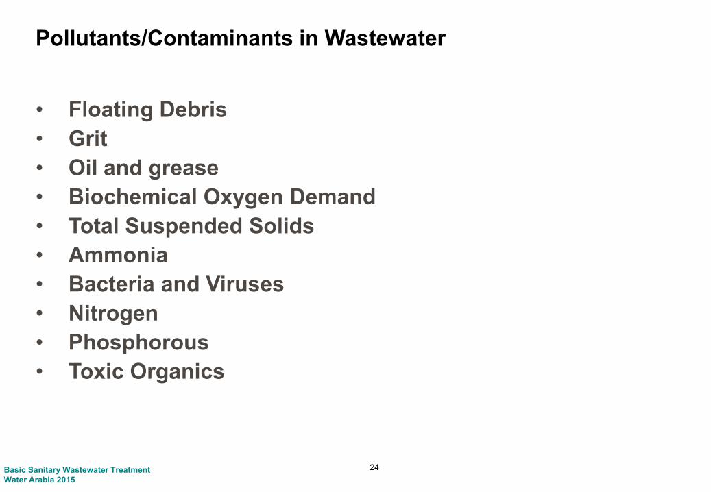
Pollutants/Contaminants in Wastewater
• Floating Debris• Grit • Oil and grease • Biochemical Oxygen Demand• Total Suspended Solids• Ammonia• Bacteria and Viruses• Nitrogen• Phosphorous• Toxic Organics
24Basic Sanitary Wastewater TreatmentWater Arabia 2015

Raw Sewage
Basic Sanitary Wastewater TreatmentWater Arabia 2015

Screenings
• Unsightly in discharge and residual solids• Can damage equipment in plant• Floating debris - plastics, sticks, paper
Basic Sanitary Wastewater TreatmentWater Arabia 2015

Grit
• Generally inert, not treatable• Damaging to equipment in plant• Sand, egg shells, plastic particles, coffee grounds
Basic Sanitary Wastewater TreatmentWater Arabia 2015

Fats, Oil & Grease
• Can affect settling of sewage• Creates foam, scum• Unsightly in discharge• Organic and inorganic sources
Basic Sanitary Wastewater TreatmentWater Arabia 2015

Pollutants/Contaminants in Wastewater
• BOD – Biochemical Oxygen Demando Removes oxygen from river watero Harmful to fish if depletes oxygen in aquatic environmento Organic compounds
• TSS – Total Suspended Solidso Affects water clarityo Can carry BODo Includes floating and colloidal materialo Organic and inorganic compounds
29Basic Sanitary Wastewater TreatmentWater Arabia 2015

Pollutants/Contaminants in Wastewater
• Nitrogeno Ammonia toxic in aquatic environmentso Promotes algae growth in water bodieso Ammonia, organic nitrogen, nitrates, nitrites
• Phosphorouso Promotes algae growth in aquatic environments
• Bacteria and viruseso Adverse health effects
• Toxic Materialso Can affect treatmento Toxic to humans and aquatic environmentso Phenols, organic compounds, medical wastes, metals
30Basic Sanitary Wastewater TreatmentWater Arabia 2015

Bacteria Toxic materials• Can affect treatment• Toxic to humans and
aquatic environments• Phenols, organic
compounds, medical wastes, metals
• Health effects
Basic Sanitary Wastewater TreatmentWater Arabia 2015

Basic Sanitary Wastewater TreatmentWater Arabia 2015
3. Effluent Disposal and Reuse

Sewage
Treatment
Works
BOD = 250 mg/L BOD < 25 mg/L
River /
Sea
BOD = 2.5 mg/L
Sludge
Disposal
Simplified Principle
Basic Sanitary Wastewater TreatmentWater Arabia 2015

Surface Water Discharge
Basic Sanitary Wastewater TreatmentWater Arabia 2015
35
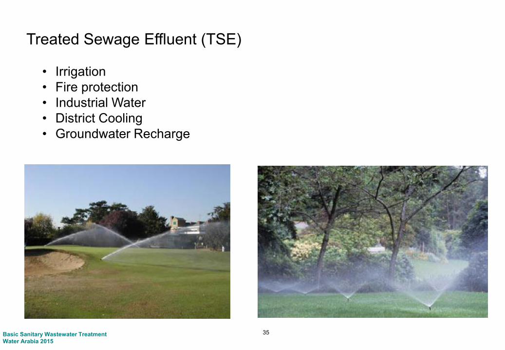
Treated Sewage Effluent (TSE)
• Irrigation• Fire protection• Industrial Water• District Cooling• Groundwater Recharge
Basic Sanitary Wastewater TreatmentWater Arabia 2015

Kranji – SINGAPOREWater reclamation for sustainable water supply
1. Rainwater
2.Raw water
Import
3. NEWater
Reservoir
Waterworks
PopulationIndustries
Commercial
Water
Reclamation
Plants
NEWaterFactories
Desalted Water4. Seawater
www.pub.gov.sg/NEWater


BrownwoodBig Spring
First US Cities to recycle water for potable use.
Wichita Falls

Basic Sanitary Wastewater TreatmentWater Arabia 2015
4. Types of Treatment

Types of Treatment
• Physical Treatment (Screening, settling, non-biological filters)o Removes debris, floatable material, coarse solids, fine solids
• Chemical Treatment (Disinfection, polymer, etc.)o Combines with soluble contaminantso Coagulation of solids for separationo Disinfectiono Water quality adjustment – pH, buffering
• Biological Treatment (Biological Filter, activated sludge, SBR, MBR)o Removes or converts biodegradable organicso Converts Ammonia and nitrogen compoundso Removes soluble Phosphates
40Basic Sanitary Wastewater TreatmentWater Arabia 2015

Process Flow Diagram – Activated Sludge with Filtration
FiltrationSecondary Settling
DisinfectionPrimary Settling
Biological Treatment
Screening
Influent Pumping
Screenings
Primary Sludge
Secondary Sludge
Grit
Grit/Grease Removal
Grease
41
Return Activated Sludge
Basic Sanitary Wastewater TreatmentWater Arabia 2015

Grit
Grit/Grease Removal
Grease
Process Flow Diagram – Trickling Filter
Secondary Clarifier
Chlorine Contact
Primary Settling
Screening
Influent Pumping
Screenings
Primary Sludge
Secondary Sludge
Trickling Filter
RecirculationPumping
42Basic Sanitary Wastewater TreatmentWater Arabia 2015

Grit
Grit/Grease Removal
Grease
Process Flow Diagram – Membrane Bioreactor
Ultraviolet Disinfection
Aeration TankScreening
Influent Pumping
Return Sludge
Screenings
Membrane Bioreactor
43Basic Sanitary Wastewater TreatmentWater Arabia 2015

Basic Sanitary Wastewater TreatmentWater Arabia 2015
5. Decision-making for Treatment
Wastewater Treatment Planning
– Population projections
– Location of treatment plants
– Disposal/reuse options
– Value of land
– Siting configurations (topography)
– Cost-effectiveness
45Basic Sanitary Wastewater TreatmentWater Arabia 2015

Population Projections
2000 2010 2020 2030
Lowest Growth Rate
Highest Growth Rate
?
Basic Sanitary Wastewater TreatmentWater Arabia 2015

47Basic Sanitary Wastewater TreatmentWater Arabia 2015

Water Network Existing
Water Network Future
Service Area Conditions and Expansion
Sewer Network Future
Sewer Network Existing
TSE Network Existing
TSE Network Future
Basic Sanitary Wastewater TreatmentWater Arabia 2015

Treatment Process Considerations
Treatment Process Decisions can be affected by:
• Site Configuration and Geology
• Initial and Future Capacity
• Effluent Standards
• Automation Required
• Flexibility of Treatment
• Proximity to Development
There are an infinite number of configurations in wastewater treatment
Basic Sanitary Wastewater TreatmentWater Arabia 2015

50
Decentralized Treatment – Satellite Plant
The Water Academy
Return Flow to Sewer
Reclaimed Water Distribution
Package Treatment BuildingExisting Park Maintenance Building
Extraction Pump Station
Reclamation of wastewater and treatment system located close to the point of reuse
Solids discharged back to a centralized collection system

Basic Sanitary Wastewater TreatmentWater Arabia 2015
Break

Basic Sanitary Wastewater TreatmentWater Arabia 2015
Preliminary and Primary Treatment

Basic Sanitary Wastewater TreatmentWater Arabia 2015
1. Preliminary Treatment

Influent Pumping/Flow Measurement
Influent Pumping sets the hydraulic profile for the treatment plant. It can provide dampened delivery of wastewater with large wetwell design and VFDs. Influent pumping stations often take plant recycles.Coarse screening ahead of pumps can remove large solids before pumping. Alternatively, grinder systems are designed to allow pumps to deliver solids to the plant headworks. Flow measurement may be provided with flumes upstream of the wetwell, or pump discharge meters.
54
FiltrationSecondary Settling
DisinfectionPrimary Settling
Biological Treatment
Grit/Grease Removal
Screening
Influent Pumping
Grit
Screenings
Primary Sludge
Secondary Sludge
Grease
Basic Sanitary Wastewater TreatmentWater Arabia 2015

Influent Pumping
• Required in many plants, where plant hydraulics not available naturally
• Submersible or wet well/dry well• Coarse screening frequently
used• Constant speed or variable
speed pumps• Odors and odor control• Health and safety
55Basic Sanitary Wastewater TreatmentWater Arabia 2015

Pump Station Scale
– Small – Less than 100 l/s
– Medium – 100 to 300 l/s
– Large – Greater than 300 l/sec
– Wet Well - Submersible
– Dry Well / Wet Well
– Dry Well
56Basic Sanitary Wastewater TreatmentWater Arabia 2015

Wet Wells
57Basic Sanitary Wastewater TreatmentWater Arabia 2015

Dry Well Installations
58Basic Sanitary Wastewater TreatmentWater Arabia 2015

Large Scale
59Basic Sanitary Wastewater TreatmentWater Arabia 2015

Influent Monitoring
• On pumped flow or in inlet works channel
• Flow monitoring with magnetic flow meter or Parshall flume
• Quality monitoring by influent sampling –Temperature, pH, TSS, BOD, Ammonia-N, alkalinity
60Basic Sanitary Wastewater TreatmentWater Arabia 2015

Preliminary Treatment
Preliminary treatment is required to remove inert materials that can be screened or settled from the raw sewage to prevent damage to equipment, and clogging of pipes and tanks (plastics, paper, inert floatables, etc.).
Preliminary Treatment includes pre-screening ahead of pumps, fine screens, grit removal and floatable grease removal.
61
FiltrationSecondary Settling
DisinfectionPrimary Settling
Biological Treatment
Grit/Grease Removal
Screening
Influent Pumping
Grit
Screenings
Primary Sludge
Secondary Sludge
Grease
Basic Sanitary Wastewater TreatmentWater Arabia 2015

Influent Screening
• Screen or bar racko A device with openings, generally of uniform size, that is used to retain solids o Screening element may consist of parallel bars, wire mesh, or perforated plateo Usually mechanically cleaned with automatic screenings removal
• Classification of screenso Bar Racks: Screens with large openings to capture large debris which cannot be pumped o Fine screens: Common in all treatment plants to remove debris as small as cigaretteso Ultrafine screens: Used ahead of membrane treatment systems for capture of small solids that
can accumulate in a membrane system
62
Item Location Opening Sizemm
Coarse Bar Racks/Trash Racks
Ahead of Influent Pumps 24 – 72
Fine Screens Headworks - Typical 6 - 12
Ultra Fine Screens Ahead of Membrane Systems 1 - 3
Basic Sanitary Wastewater TreatmentWater Arabia 2015

Coarse Screens (Bar Racks)
• Clear openings ranging from 6 to 150 mm
• Manually or mechanically, front (upstream) or back (downstream) cleaned
• Manually cleaned screens are usually used for small WWTPs or as standby/overflow in larger WWTPs
• Volume of screenings removed is 6 – 50 l/1,000 m3
• Might not be needed if provided at the pump stations upstream from the WWTP
63
Design Parameters
Clear opening 25 to 44 mm
Approach Velocity 0.3 to 0.6 m/sec
Width of the bar 5 to 15 mm
Basic Sanitary Wastewater TreatmentWater Arabia 2015

Fine Screens
• Clear openings less than 6 mm• Openings as small as 1 mm• Mechanically cleaned• Usually following coarse screening• Could remove up to 50% of TSS and BOD• Washing is critical for the operation
64Basic Sanitary Wastewater TreatmentWater Arabia 2015

Band Screens: 2 - 4 mm
• Flow goes in thru center and passes thru perforations on side screens
• Screenings are carried by lifting trays and are discharged via gravity/spray into a flume above deck level
• PE links form chains on either side to drive screen
• Screenings are dewatered in a screw compactor before discharging
65Basic Sanitary Wastewater TreatmentWater Arabia 2015

Drum Screens: 6 - 9 mm
• The screening medium is mounted on a cylinder (drum) that rotates in a flow channel
• Flow goes in thru both sides and passes thru perforations in the screen panels out of the drum
• Screenings are carried by elevating plates and are discharged via gravity/spray water into a flume Inside the drum
• External Bypass channel required (no integral bypass)
• Screenings discharge into a common wet well and are pumped (or flow by gravity) to a liquid-solids separator unit, where they are dewatered before discharging into a screenings skip
66Basic Sanitary Wastewater TreatmentWater Arabia 2015

Alternative Drum Screen
67Basic Sanitary Wastewater TreatmentWater Arabia 2015

Screening – Design Considerations
• Size (clear openings)• Approach velocity• Straight approach• Designed based on peak flow• Headloss• Head space required• Screenings handling (raking), processing and disposal• Duty and standby units• Odour control• Washing• Control (Differential headloss and timer)
68Basic Sanitary Wastewater TreatmentWater Arabia 2015

Grit Removal
• Grit Removal is done by gravity settling or by centrifugal separation of solids
• Located after bar screens and before primary sedimentation
• Types of Grit Removalo Aerated grit chambero Horizontal settlingo Vortex grit chamber
• Average grit removed is4 - 40 l/1,000 m3
69Basic Sanitary Wastewater TreatmentWater Arabia 2015

Aerated Grit Chambers
• Air is introduced along one side of a rectangular tank to create a spiral flow pattern
• Heavier grit particles settle to the bottom
• Lighter particles pass through the tank
• Organics create odors and attract insects
• The velocity of roll governs the size of particles removed
• Normally designed to remove 0.21 mm diameter (65 mesh) or larger with 2-5 minute detention time at the peak hourly flow
• Grit is removed through grab buckets or pumps from grit sumps– travelling on monorails, screw
conveyor, – grit pumps or airlift
• Covers maybe required if release of VOCs is a concern
70Basic Sanitary Wastewater TreatmentWater Arabia 2015

Aerated Grit Chamber Design Parameters
Parameters Range
Detention Time (Mins.) at Max. Flow 2 - 5
Depth (m) 2 - 5
Length (m) 7 - 20
Width (m) 2.5 - 7
Width - Depth Ratio 1:1 - 5:1
Length - Width Ratio 3:1 - 5:1
Air Supply (m3/hr./m of length) 10 – 25
Grit Quantities (l/1000 m3) 3.7 - 56
71Basic Sanitary Wastewater TreatmentWater Arabia 2015

Vortex Grit Removers
• Flow enters/exits chamber tangentially• Vortex induced naturally thru tangential
flow and by mechanical paddle at bottom of chamber, grit migrates to center of chamber and is stored in grit hopper
• Collector drive is on top of unit• Grit removed from grit hopper by
pumping to a cyclone separator and grit classifier
• Internal use water for grit washing• Grit pumps can be in basement or top-
mounted • Detention time ~ 30 sec range• Typically 1- 7 m in diameter and
2.5 – 5 m in depth
72Basic Sanitary Wastewater TreatmentWater Arabia 2015

Vortex Design Parameters
Parameters RangeDetention Time (s) 30Diameter (ft) 4 - 24Height (ft) 9 - 16
Removal Rates (%)50 mesh (0.3 mm) 95+70 mesh (0.24 mm) 85+100 mesh (0.15 mm) 65+
73Basic Sanitary Wastewater TreatmentWater Arabia 2015

Grit Removal Design Considerations
• Detention time - based on peak flow• Size of particle removed• Headloss• Grit handling (collection), dewatering and disposal• Duty and standby units• Oil and grease removal• Odor control
74Basic Sanitary Wastewater TreatmentWater Arabia 2015

Headworks Designs
75Basic Sanitary Wastewater TreatmentWater Arabia 2015
Basic Sanitary Wastewater TreatmentWater Arabia 2015
2. Primary Treatment

Primary Clarification
Primary Treatment is the physical separation of settleable solids in rectangular settling tanks or circular clarifiers, with detention time of 2 hours or more. Settled solids are removed mechanical sludge collectors, and sludge is further treated. Floating solids are skimmed from the surface.
77
FiltrationSecondary Settling
DisinfectionPrimary Settling
Biological Treatment
Grit/Grease Removal
Screening
Influent Pumping
Grit
Screenings
Primary Sludge
Secondary Sludge
Grease
Basic Sanitary Wastewater TreatmentWater Arabia 2015

Primary Treatment
78
Item Hydraulic Retention,
Hours
TSS Removal % BOD removal %
Circular Clarifiers 2 - 3 40 – 60 20 – 30
Rectangular Clarifiers 2 – 3 40 – 60 20 – 30
Lamella Clarifiers 1.5 – 2 40 – 70 25 – 40
Chemically Enhanced Primary Treatment (CEPT)
1.5 - 2 50 - 75 30 – 50
• Up to 70% removal of TSS and up to 50% removal of BOD• Reduce power cost associated with secondary treatment• Could be supplemented with chemical addition for enhanced sedimentation
and/or P removal• Mechanically cleaned sedimentation tanks of standardized circular or
rectangular design. • Multiple tanks should be provided so that the process may remain in
operation while one tank is out of service for maintenance
Basic Sanitary Wastewater TreatmentWater Arabia 2015

Rectangular Tanks
• Horizontal flow • Depth: 4 m; Width: 5 – 10 m;
Length: 25 – 40 m• Chain-and-flight solids collectors
or traveling-bridge-type collectors
79Basic Sanitary Wastewater TreatmentWater Arabia 2015

Circular Tanks
• Flow pattern is radial and wastewater is usually introduced in the center of the tank
• Require larger footprint• Depth: 4 m; Diameter: 12 - 45 m
80Basic Sanitary Wastewater TreatmentWater Arabia 2015

Lamella Clarifier/Plate Settlers
• Rack of inclined metal plates, which cause flocculated material to precipitate from water that flows across the plates.
• Smaller footprint than conventional clarification equipment for the same solids removal capacity
• Compact design eliminates hydraulic disturbances caused by wind or temperature changes.
• Balanced flow distribution ensures equal flow to each plate and across the plate surface area, preventing short-circuiting.
• Minimal moving parts means low maintenance costs.
81Basic Sanitary Wastewater TreatmentWater Arabia 2015

Primary Settling Design Considerations
• Surface overflow rate (m3/m2/d) - based on peak flowTypically 80 – 120 m3/m2/d
• Baffling to reduce short circuiting• Grit handling (collection), dewatering and disposal• Duty and standby units• Odor• Pumping of primary sludge (3 -5 % solids)• Scum removal• Detention times ranging between 2 to 5 hours use a settleometer to check
how long solids can be in the clarifier without floating
82Basic Sanitary Wastewater TreatmentWater Arabia 2015

Basic Sanitary Wastewater TreatmentWater Arabia 2015
Break
Basic Sanitary Wastewater TreatmentWater Arabia 2015
Biological Treatment Processes

Biological TreatmentFiltrationSecondary
SettlingDisinfectionPrimary
SettlingActivated Sludge
(Suspended Growth)Grit/Grease
RemovalScreening
Influent Pumping
Grit
Screenings
Primary Sludge
Secondary Sludge
Grease
Biological processes usually include a reactor and a solids separation step. Most commonly the separation system is a settling tank.
Biological processes: bacteria and protozoa to react with organic matter and nutrients, oxidizing them under controlled conditions. Biological treatment works because of high populations of bacteria (biomass) in relation to the food (organics, nutrients) that enter the treatment process.
Fixed Film (Attached Growth)
RecirculationPumping
Secondary Sludge

Biological Treatment Processes
• Removes or converts biodegradable organics
• Converts Ammonia and Nitrogen compounds
• Removes soluble Phosphates
Activated Sludge Processes• Extended aeration• Oxidation ditch• Step Feed• SBR’s
Fixed Film Processes• Trickling filters• Biological Aerated Filters (BAF’s)• Submerged Aerated Filters
(SAF’s)• Rotating Biological Contactors
86Basic Sanitary Wastewater TreatmentWater Arabia 2015

Basic Sanitary Wastewater TreatmentWater Arabia 2015
1. Activated Sludge Process

Activated Sludge Processes
• Activated sludge microbes (biomass) • Oxygen rich environment• Organic material in wastewater used
as food source• Generating growth of biomass and
clean water• Suspended growth process• Biomass in free suspension to ensure
adequate contact with wastewater• Correct microbes settle well• Settlement process allows treated
effluent to be drawn off and biomass to settle
• Biomass kept alive by recycling a portion of settled biomass to activated sludge tank as growth medium to generate more biomass
• Excess bacteria removed as sludge
88
Activated
Sludge
Microbe
Sewage
Oxygen
Basic Sanitary Wastewater TreatmentWater Arabia 2015

Activated Sludge Processes
• Many variations of activated sludge to treat municipal wastewaters• Typically follows primary sedimentation in order to reduce the solids and
organic (BOD and COD) loading• Process includes an aeration stage followed by a settlement tank
89
Influent MLSSEffluent
Surplus
sludge
Air
Aeration Tank Settling Tank
Recycled sludge
MLSS = Mixed Liquor Suspended Solids
Basic Sanitary Wastewater TreatmentWater Arabia 2015

Activated Sludge Processes
• Biomass is freely suspended in wastewater and feeds on the organic matter in the presence of oxygen
• Important operating and design parameters are HRT, MLSS, SRT, F/M, DO, SVI• Sludge is produced as BOD is removed and needs to be removed to maintain
optimum treatment conditions• The dissolved oxygen required for the process can be provided by
mechanical agitation or diffused air• Varying degrees of treatment can be achieved:
o Carbonaceous : BOD removalo Nitrification : Ammonia Removalo Denitrification : Nitrogen Removal
• There are many variants of the AS process which can be designed to achieve the required degree of treatment
• The sequencing batch reactor eliminates the requirement for primary and secondary settlement. All processes in one tank.
90Basic Sanitary Wastewater TreatmentWater Arabia 2015

March 12, 2015
Table 7-6 Classification of microorganisms
Type of Bacteria
Common reaction Name
Carbon Source
Electron donor (substrate oxidized)
Electron Acceptor
Products
Aerobicheterotrophic
Aerobicoxidation
Organic compounds
Organic compounds
O2 CO2, Hp
Aerobicautotrophic
Nitrification CO2 NH3, NO:; O2 NO:;, N03
Iron oxidation CO2 Fe(lI) O 2 Ferric Iron [Fe(llI)]
Sulfuroxidation CO2 H2S, S°, S2O3-- O2 SO2--
Facultativeheterotrophic
Denitrification anoxic reaction
Organic compounds
Organiccompounds
NO:;, NOj N2, CO2, H2O
Anaerobicheterotrophic
Acid fermentation Organic compounds
Organic compounds
Organic compounds
Volatile fatty acids(VFAs) {acetate, propionate, butyrate}
Iron reduction Organic compounds
Organic compounds
Fe(lIl} Fe {II}, CO2, H2O
Sulfate reduction Organic compounds
Organic compounds
S04 H2S, CO2, H2O
Methanogenesis Organic compounds
Volatile fattyacids {VFAs}
CO2 Methane

Activated Sludge Processes
– Step Feed• Modification of conventional plug flow process. The feed is introduced at a
number of places in the aeration tank. The concept is to even out F/M and reduce oxygen demand
– Extended Aeration• HRT and sludge age much higher than conventional process, encouraging
greater degradation of the MLSS. Less sludge for disposal and BOD removals of 98%
– Oxidation Ditch• Best known extended aeration system. Mixed liquor circulates in a
continuous channel or ‘race track’ aerated by a horizontal rotor which maintains velocity to prevent settlement
92Basic Sanitary Wastewater TreatmentWater Arabia 2015

Typical Design Parameters
Process SRT, d F/M kgBOD/kg MLVSS-d
Volumetric LoadingkgBOD/m3-d
MLSS mg/L RAS % of influent
Conventional 3 -15 0.2-0.6 0.3-1.6 1500-4000 25 - 100
Conventional plug flow
3 – 15 0.2 – 0.4 0.3 – 0.7 1000 – 3000 25 - 75
Step feed 3 – 15 0.2 – 0.4 0.7 – 1.0 1500 – 4000 25 - 75
Extended aeration 20 – 40 0.04 – 0.1 0.1 – 0.3 2000 – 5000 50 - 150
Oxidation ditch 15 – 30 0.04 – 0.1 0.1 – 0.3 3000 – 5000 75 - 150
93Basic Sanitary Wastewater TreatmentWater Arabia 2015

Activated Sludge Processes
– Aeration Techniques
• Surface Aeratorso Vertical shaft or Horizontal shafto Throw activated sludge into atmosphere
as fine droplets, the contact with the air allows the mass transfer of oxygen into the liquid phase
• Diffused Airo Compressed air is fed in to the bottom of
the tank through fine pore diffusers. o The mass transfer of oxygen into the liquid
phase is via bubbles traveling up through the tank
94Basic Sanitary Wastewater TreatmentWater Arabia 2015

17 February 2015Basic Sanitary Wastewater TreatmentWater Arabia 2015
Carbonaceous Organics Treatment
BOD 20mg/L, COD 60mg/L, SS 30 mg/LNo reduction of Amm. N, TN, TP
Settled Sewage
0.8QRAS
Aerobic Q Final
Effluent
BOD + bacteria + O2 Solids + CO2 + H2O + Energy
Single Reactor, Relatively Small Volume
FST

Basic Sanitary Wastewater TreatmentWater Arabia 2015
2. Nutrient Removal Processes

Ammonia(NH3/ NH4
+)Nitrite(NO2
- )
Ammonia
Oxidizers
(Nitrosomonas)
Oxygen(O2)
Nitrate(NO3
- )
Oxygen(O2)
Nitrite
Oxidizers
(Nitrobacter)
Autotrophic Autotrophic• Grow Faster than Ammonia
Oxidizers• Die Out Faster• More Sensitive to InhibitionAlkalinity
(HCO3 -) (H+)
Alkalinity Destruction
Biological Processes - Nitrification
97Basic Sanitary Wastewater TreatmentWater Arabia 2015
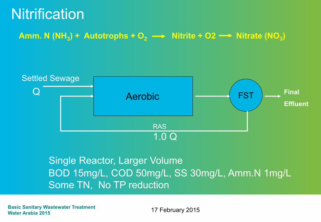
17 February 2015Basic Sanitary Wastewater TreatmentWater Arabia 2015
BOD 15mg/L, COD 50mg/L, SS 30mg/L, Amm.N 1mg/LSome TN, No TP reduction
Settled Sewage
FSTAerobicQ
NitrificationAmm. N (NH3) + Autotrophs + O2 Nitrite + O2 Nitrate (NO3)
Single Reactor, Larger Volume
1.0 QRAS
Final
Effluent

Biological Processes - Denitrification
99
Denitrifying Heterotrophs20-80% of Heterotrophic Bacteria
Nitrate(NO3
- )Nitrite(NO2
- )
Recovered Alkalinity(HCO3
-)
NitrogenGas(N2)
CarbonDioxide(CO2)
Organic Carbon Substrate
40% 60%
Basic Sanitary Wastewater TreatmentWater Arabia 2015

17 February 2015Basic Sanitary Wastewater TreatmentWater Arabia 2015
Denitrification
BOD 15mg/L, COD 50mg/L, SS 15mg/L, Amm. N <1mg/L, TN <10mg/L, No TP reduction
Settled Sewage
FST
Q RAS
Aerobic Q Final
Effluent
2 - 6 Q ML Recycle
Nitrate (NO3) + Heterotrophs + Carbon N2 (Gas)
Multiple Reactors, Larger Volume

Basic Sanitary Wastewater TreatmentWater Arabia 2015
Total Phosphorus Removal
BOD 10mg/L, COD 30mg/L, SS 10mg/L, Amm. N <1mg/L, TN <10mg/L, TP 0.5 – 1.5mg/L
Settled Sewage
FST
Q RAS
Aerobic Q Final
EffluentAnoxic
3-6Q ML Recycle
PAO + Carbon P release
PAO + O2 Enhanced P uptake1Q ML Recycle

Advanced Activated Sludge Processes
102Basic Sanitary Wastewater TreatmentWater Arabia 2015

Sequencing Batch Reactor
103Basic Sanitary Wastewater TreatmentWater Arabia 2015

Sequencing Batch Reactor
104
Basin Configuration
Basic Sanitary Wastewater TreatmentWater Arabia 2015

Sequencing Batch Reactor
105
Inflow
Mixed liquor
Inflow optional
2. React (2 hours)
1. Fill (2 hours)
Air on
Air optional
3. Settle (1 hour)
4. Decant & Idle (1 hour)
Decant
Waste sludgeMixed liquor
Basic Sanitary Wastewater TreatmentWater Arabia 2015

Sequencing Batch Reactor
106
Raised above liquid during aeration Follows liquid level down during decant
Effluent Decanter
Basic Sanitary Wastewater TreatmentWater Arabia 2015

Membrane BioReactor
107Basic Sanitary Wastewater TreatmentWater Arabia 2015

108Basic Sanitary Wastewater TreatmentWater Arabia 2015

Membrane Bioreactor
• Compact System
• No Clarifiers or Filters
• High Mixed Liquor
Concentrations Possible
• No TSS or bacteria in effluent
• Limits passage of viruses
• Small Footprint (0.3 ha/10 MLD)
• Highly automated
• Requires close monitoring
109Basic Sanitary Wastewater TreatmentWater Arabia 2015

Basic Sanitary Wastewater TreatmentWater Arabia 2015
Fixed Film Processes

What are biofilms?
–A cultured biomass attached to a support medium
–The biofilm develops according to the availability of particular wastewater components and will vary according to loading and configuration
–Aerobic biofilms require oxygen to function
–As biofilms grow via the degradation of organic compounds they produce excess biomass which need to be removed from the system
Basic Sanitary Wastewater TreatmentWater Arabia 2015

Biofilm Structure
MediaSurface
Biofilm Wastewater
Anaerobic
CO2
Aerobic
Plastic or Rock Media
O2
Basic Sanitary Wastewater TreatmentWater Arabia 2015
Fixed Film Reactors
–Also known as attached growth reactors to differentiate them from activated sludge or ‘suspended growth’ systems
–Biomass is cultured as a biofilm attached to a biomass support
–Biofilm can be applied across the whole spectrum of wastewater treatment from low rate traditional trickling filters to ultra high rate fluidised bed reactors
Fixed Film
Basic Sanitary Wastewater TreatmentWater Arabia 2015

Fixed Film Processes
• Non-submerged systemso Traditional approacho Biofilm wetted regularly but kept in an air environmento Developed in 1890’s as rock filterso Simple, low energy
• Submerged systemso Biofilm grows on media whilst completely wettedo Air supplied through aeration systemo High rate, small footprinto More complex with greater control required
114Basic Sanitary Wastewater TreatmentWater Arabia 2015

Fixed Film Processes
Trickling Filters• Non-submerged fixed film biological reactor using rock or plastic packing
over which wastewater is distributed continuously• Advantageso No aeration costso Simple to operateo Robusto Known processo Long-term experience
115Basic Sanitary Wastewater TreatmentWater Arabia 2015

Fixed Film Processes• Trickling Filters
• Media Propertieso High surface area – maximum
biofilm attachmento Voids – large pores for aerationo Non – toxic – biofilm growtho Strength – no crushingo Low Cost
• Distributiono Distribute wastewater evenly
over filtero 2 or 4 armso 30 – 55 mins / revolutiono Improved BOD removalo Insect controlo Hydraulic, motorized or static
116Basic Sanitary Wastewater TreatmentWater Arabia 2015

Fixed Film Processes
• Rotating Biological Contactorso More suitable for small workso Very low power requiremento Easily coveredo Mechanically simpleo Expensiveo Tend to have mechanical problemso Unreliable
117Basic Sanitary Wastewater TreatmentWater Arabia 2015

Biological Aerated Filter (BAF)
– Attached Growth Biological Process
– Upward Flow Through a Granular Media• Media - Surface for denitrifying
organisms• Media - Solids removal
Media Support System
Effluent
Influent
Media Retention System
Scour Air Grid
Influent Distribution Chamber
Filter Media
Basic Sanitary Wastewater TreatmentWater Arabia 2015
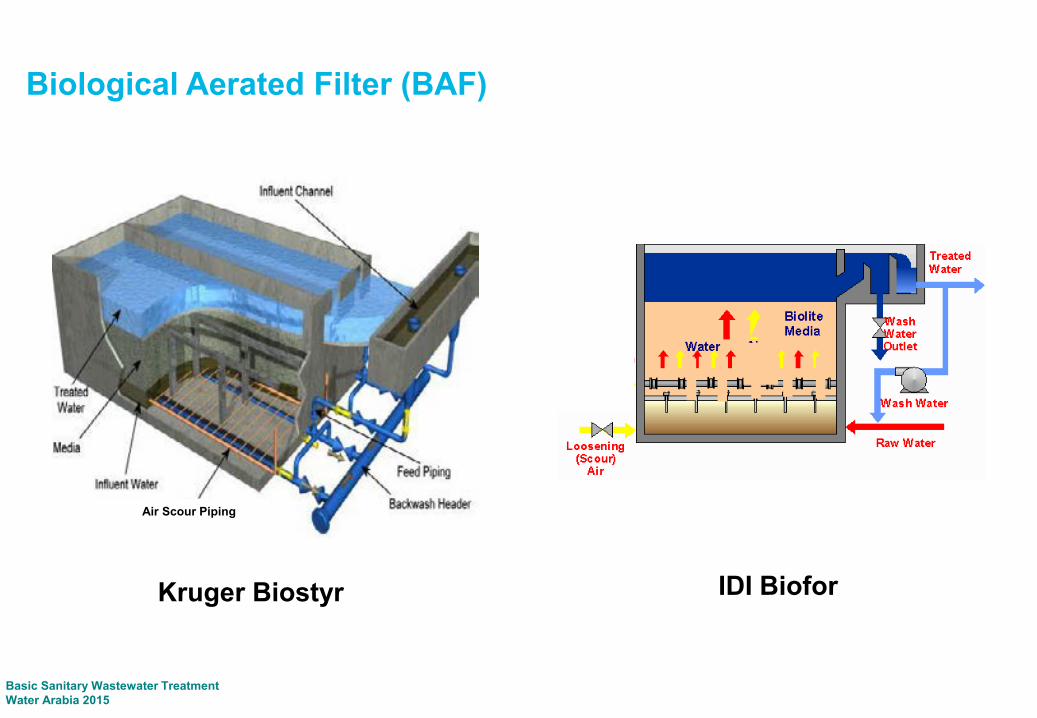
Kruger Biostyr IDI Biofor
Air Scour Piping
Biological Aerated Filter (BAF)
Basic Sanitary Wastewater TreatmentWater Arabia 2015

Basic Sanitary Wastewater TreatmentWater Arabia 2015
Hybrid Biological Processes

Moving Bed Biofilm Reactor (MBBR)
121Basic Sanitary Wastewater TreatmentWater Arabia 2015

Integrated Fixed Film Activated Sludge
122Basic Sanitary Wastewater TreatmentWater Arabia 2015
Basic Sanitary Wastewater TreatmentWater Arabia 2015
Break

17 February 2015Basic Sanitary Wastewater TreatmentWater Arabia 2015
Secondary Clarification

Secondary Clarification
• Tanks in which settleable solids from the biological treatment process are separated from the wastewater
• Design considerations and tanks are similar to those used for Primary Settlement Tanks
• Most common are circular o (10 to 50 m)
• Rectangular tanks can also be used
125Basic Sanitary Wastewater TreatmentWater Arabia 2015
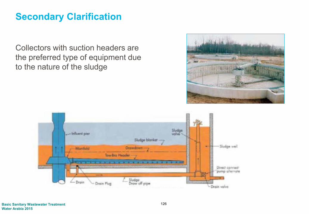
Secondary Clarification
Collectors with suction headers are the preferred type of equipment due to the nature of the sludge
126Basic Sanitary Wastewater TreatmentWater Arabia 2015

Basic Sanitary Wastewater TreatmentWater Arabia 2015
Filtration

Filtration
Filtration is used to remove small solids that may leave the secondary clarifiers. It is used to achieve TSS levels of less than 5 mg/L. Microfilters and ultrafiltration can achieve TSS levels less than 1 mg/L and turbidity less than 1 NTU.
Filtration can be used for tertiary treatment to remove contaminants such as phosphorus and nitrogen with chemicals or through biological activation.
128
FiltrationSecondary Settling
DisinfectionPrimary Settling
Biological Treatment
Grit/Grease Removal
Screening
Influent Pumping
Grit
Screenings
Primary Sludge
Secondary Sludge
Grease

Filtration
– Types of Filtration
• Sand Filterso Gravel, sand, other granulated materialo Dual, multi layer or multi media filters
• Membraneso Ultra filters, act as sieveso .001- 10 micron
• Biofilm Filtration (Disc or Trickling)o Biofilter using microorganism
129Basic Sanitary Wastewater TreatmentWater Arabia 2015

Disc Filters
130Basic Sanitary Wastewater TreatmentWater Arabia 2015

Deep Bed Filters
131Basic Sanitary Wastewater TreatmentWater Arabia 2015

Low Head Filters
132Basic Sanitary Wastewater TreatmentWater Arabia 2015

Fluidized Bed Filter
133Basic Sanitary Wastewater TreatmentWater Arabia 2015

Basic Sanitary Wastewater TreatmentWater Arabia 2015
Disinfection

Disinfection
Disinfection removes remaining bacteria and viruses that could be harmful to fish or humans if in great concentration. TSE is disinfected for health reasons and to reduce bacteria growth in reuse mains.
Disinfection is required ahead of disposal or reuse under most conditions. May not be required for dedicated land application, subsurface disposal or disposal to non-critical waterways.
135
FiltrationSecondary Settling
DisinfectionPrimary Settling
Biological Treatment
Grit/Grease Removal
Screening
Influent Pumping
Grit
Screenings
Primary Sludge
Secondary Sludge
Grease

Disinfection
Chlorination• Most commonly used
• 15 minutes contact time to remove most bacteria
• 30 minutes chlorine contact time to kill giardia cysts
Ultraviolet Radiation
• 20-30 second contact time
• Inactivates viruses
• No chemical addition
• No residual disinfectant
Ozone
• Strong Oxidant 136

137Basic Sanitary Wastewater TreatmentWater Arabia 2015
Ozonation

Basic Sanitary Wastewater TreatmentWater Arabia 2015
Odour Treatment

Classification of odours
Odour threshold (ppb)
Long Term OEL (8-Hour) (ppm)
Short term OEL (15 minutes) (ppm)
Hydrogen Sulphide 0.5 5 10Methyl Mercaptan(methanethiol)
0.0014-18 0.5 -
Ethylmercaptan(ethanethiol)
0.02 0.5 2
Ammonia 130-15300 25 35Methylamine 0.9-53 10 -Ethylamine 2400 10 -Dimethylamine 23-80 10 -
139Basic Sanitary Wastewater TreatmentWater Arabia 2015

Why Hydrogen Sulphide
WHO guidelines for H2S.
1000-2000 ppm Immediate collapse with paralysis of respiration
530-1000 ppm Strong Central Nervous system stimulation followed by respiratory arrest
320-530 ppm Risk of Death
150-250 ppm Loss of olfactory sense
50-100 ppm Serious eye damage
10-20 ppm Theshold for eye irritation
140Basic Sanitary Wastewater TreatmentWater Arabia 2015

Why Hydrogen Sulphide
The importance of Hydrogen Sulphide in odour work
• It is almost always a component of wastewater odour
• It is always a component of septic wastewater odour
• It can be measured at concentrations close to its threshold
• Predictive models can be used
• In 99 cases out of 100, if the generation and release of H2S is controlled so is the odour problem.
141Basic Sanitary Wastewater TreatmentWater Arabia 2015
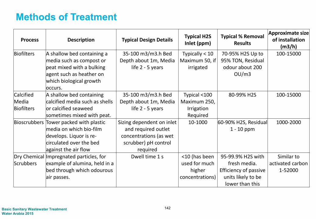
Methods of Treatment
Process Description Typical Design DetailsTypical H2S Inlet (ppm)
Typical % Removal Results
Approximate size of installation
(m3/h)Biofilters A shallow bed containing a
media such as compost or peat mixed with a bulking agent such as heather on which biological growth occurs.
35-100 m3/m3.h Bed Depth about 1m, Media
life 2 - 5 years
Typically < 10 Maximum 50, if
irrigated
70-95% H2S Up to 95% TON, Residual odour about 200
OU/m3
100-15000
Calcified Media Biofilters
A shallow bed containing calcified media such as shells or calcified seaweed sometimes mixed with peat.
35-100 m3/m3.h Bed Depth about 1m, Media
life 2 - 5 years
Typical <100 Maximum 250,
Irrigation Required
80-99% H2S 100-15000
Bioscrubbers Tower packed with plastic media on which bio-film develops. Liquor is re-circulated over the bed against the air flow
Sizing dependent on inlet and required outlet
concentrations (as wet scrubber) pH control
required
10-1000 60-90% H2S, Residual 1 - 10 ppm
1000-2000
Dry Chemical Scrubbers
Impregnated particles, for example of alumina, held in a bed through which odourousair passes.
Dwell time 1 s <10 (has been used for much
higher concentrations)
95-99.9% H2S with fresh media.
Efficiency of passive units likely to be lower than this
Similar to activated carbon
1-52000
142Basic Sanitary Wastewater TreatmentWater Arabia 2015

143
Process Description Typical Design DetailsTypical H2S Inlet (ppm)
Typical % Removal Results
Approximate size of installation
(m3/h)
Activated Carbon
Granules of high surface area carbon are held in a bed through which odourous air passes
Bed Depth about 0.25m Velocity 0.2-0.38 m/s,
Dwell time 2s, usually 2 or 3 beds
<10 95-99/9% H2S with fresh media.
Efficiency of passive units likely to be lower than this
Fan assisted 360-72000 Passice
1-1800
Catalytic Iron Filter
Iron Oxide held in a vertical or horizontal unit over which sulphide containing air passes.
500 50% 100-15000
Wet Chemical Scrubbers
Odourous air is contacted with a flow of recirculatingliquid which dissolves and removed the odourouschemicals.
Sizing dependent on inlet and required outlet
concentrations, pH control required
<10-1000 95-99% H2S 85-95% Odour
1000-100000
Basic Sanitary Wastewater TreatmentWater Arabia 2015

Activated Carbon Filters
144Basic Sanitary Wastewater TreatmentWater Arabia 2015

Chemical Scrubbers
145Basic Sanitary Wastewater TreatmentWater Arabia 2015

BioScruber
• Targets H2S specifically for oxidation.
• Fixed-film biological process which takes advantage of H2S’s water solubility.
• Designed to reduce H2S concentrations by 99% (12 to 15 sec.)
• Engineered inorganic media used as fixed bed material
• Microorganisms in Recirculating Water

Biotrickling Filter
• Media can be stacked, high void fraction –low resistance to air flow
• Higher air velocities – allowing smaller footprint than conventional biofilters
• Generally No recirculation• Higher Capital cost• Low operational cost• Low Maintenance• Media Replacement (10 – 25 years)• Can remove other odour compounds

Biofilter
• A biofilter odor control system is based on adsorption and bacterial decomposition of odorous compounds
• Modern media require no added chemicals for treatment
• Various system designs;• Custom Built in place• Custom Modular• Prefabricated units
• Organic Media (5 years)
• Inorganic media (10+ Years)

Basic Sanitary Wastewater TreatmentWater Arabia 2015
Break

Basic Sanitary Wastewater TreatmentWater Arabia 2015
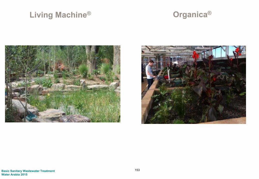
Small Treatment Systems

151Basic Sanitary Wastewater TreatmentWater Arabia 2015

152
Living Machine®
Basic Sanitary Wastewater TreatmentWater Arabia 2015
153
Living Machine® Organica®
Basic Sanitary Wastewater TreatmentWater Arabia 2015
Basic Sanitary Wastewater TreatmentWater Arabia 2015
Biological Process Modeling

Wastewater Process Modeling Software
155Basic Sanitary Wastewater TreatmentWater Arabia 2015

Biological Process Modeling
Different process units can be included to "build" a specific treatment plant configuration and model any condition
156Basic Sanitary Wastewater TreatmentWater Arabia 2015

BioWin Process Diagram
157Basic Sanitary Wastewater TreatmentWater Arabia 2015

Basic Sanitary Wastewater TreatmentWater Arabia 2015
Break

Basic Sanitary Wastewater TreatmentWater Arabia 2015
Sludge Treatment

Sludge Treatment
– What is Sludge?
• Wastewater sludge comes from:• Primary Sludge: Settled solids from raw wastewater, mostly TSS, from Primary
Settling Tanks• Secondary Sludge: Live and dead bacteria from biological treatment processes,
which are settled in the Secondary Settling Tanks
160Basic Sanitary Wastewater TreatmentWater Arabia 2015

Sludge Treatment
– Why treat sludge?
• Need to dispose of the sludge• Wastewater sludge smells• Contains high level of fecal bacteria
• Disposal Options• Burning• Recycle to land
• Sludge from the settlement tanks is low in solids contents, concentrations between 0.5% and 2% solids.
• Treatment will concentrate the solids and reduce the volume to be disposed
• Treatment will also reduce odors and the level of fecal bacteria
161Basic Sanitary Wastewater TreatmentWater Arabia 2015

Sludge Treatment
• Thickening• Gravity Thickening• Gravity Belt Thickening• Rotary Drum Thickening• Dissolved Air Flotation Thickening
• Digestion• Aerobic Digestion• Anaerobic Digestion
• Dewatering
• Drying
• Incineration
162Basic Sanitary Wastewater TreatmentWater Arabia 2015

Sludge Treatment – Aerobic Digestion
163
DisposalDewateringDigestionThickening
PS – Primary SludgeSS – Secondary SludgeTS – Thickened SludgeDS – Digested Sludge
Gravity Thickener
Aerobic Digester
Belt Filter Press
Centrifuge
SSPS
TS To LandfillOr Land
Application
Basic Sanitary Wastewater TreatmentWater Arabia 2015

Dewatering Incineration
DigestionThickening
Gravity Thickener
Gravity Belt Thickener
Anaerobic Digester
Centrifuge
Biogas Storage
Incinerator
Biogas-powered Engine/Generator
PS – Primary SludgeSS – Secondary SludgeTS – Thickened SludgeDS – Digested Sludge
SS
PS
Ash to Landfill
Dewatered Sludge to Land Application
Electricity to Plant
Sludge Treatment – Anaerobic Digestion
164Basic Sanitary Wastewater TreatmentWater Arabia 2015

Basic Sanitary Wastewater TreatmentWater Arabia 2015
Sludge Thickening

Sludge Thickening
• Gravity Thickening• Process similar to settlement tanks in
the liquid stream process• Works well for primary sludge but can
be used for secondary sludge with polymer addition
• Requires cover and odor control in case of process upset
• Can increase solids from 1.5 – 2% to 4 – 6%
166Basic Sanitary Wastewater TreatmentWater Arabia 2015

Sludge Thickening
• Gravity Thickening Design Parameters
167
Design Parameter RangeDiameter 10 – 25 mSidewater Depth 3 – 5 mSolids Loading Rate 100 – 150 kg/m2/d (PS)
25 – 70 kg/m2/d (Combined PS & SS)Hydraulic Overflow Rate 15.5 – 31 m3/m2/d (PS)
6 – 12 m3/m2/d (Combined PS & SS)Sludge Blanket Depth 0.5 – 2.5 m
Basic Sanitary Wastewater TreatmentWater Arabia 2015

Sludge Thickening
• Gravity Belt Thickening• Liquid from sludge is removed through
pores in woven plastic belt• Works well for secondary sludge• Polymer addition required for efficient
operation• Can increase solids from 0.5 – 2% to 4 –
8%
168Basic Sanitary Wastewater TreatmentWater Arabia 2015

Sludge Thickening
• Gravity Belt Thickening Design Parameters
169
Design Parameter Range
Belt Width 1 – 3 m
Solids Loading Rate 200 – 600 kg/m/hr
Hydraulic Overflow Rate 20 – 58 m3/m/hr
Polymer Dosage 3 – 7 kg of dry polymer/metric ton
Basic Sanitary Wastewater TreatmentWater Arabia 2015

Sludge Thickening
• Rotary Drum Thickening• Slowly rotating drum aids removal of liquid
from sludge and concentrates solids• Liquid from sludge is removed through
pores in metal screen inside drum• Works well for both primary and secondary
sludge• Polymer addition improves efficiency• Can increase solids from 0.5 – 2% to 4 –
8%• Up to 85 m3/hr capacity
170Basic Sanitary Wastewater TreatmentWater Arabia 2015

Sludge Thickening
• Dissolved Air Flotation Thickening• Uses small air bubbles to which
sludge particles attach and float to water surface
• Works well for secondary sludge• Polymer addition required for
efficient operation• Can increase solids from 0.5 – 2% to
4 – 8%• Requires additional support
equipment (pressure vessels, air compressors and circulation pumps)
• Solids loading rates• 1 – 6 kg/m2/hr without chemical
addition• Up to 10 kg/m2/hr with chemical
addition
171Basic Sanitary Wastewater TreatmentWater Arabia 2015

Sludge Thickening
• Centrifuge Thickener• Performance by percent capture• Liquid from sludge is removed through
centrifugal action• Works well for secondary sludge• Polymer addition required for increased
solids content• Can increase solids from 0.5 – 2% to 3 –
8%
172Basic Sanitary Wastewater TreatmentWater Arabia 2015

Basic Sanitary Wastewater TreatmentWater Arabia 2015
Digestion
Sludge Digestion
• Process• Reduces the concentration of organic solids in sludge• Results in less sludge to process, decreases operating time and reduces size
of dewatering equipment
• Anaerobic Digestion• Uses heated sludge in a tank with a low concentration of air• Process produces methane gas which can be utilized to heat the sludge and
for cogeneration• Results in varying degrees of destruction of harmful bacteria• Must be used if dewatered sludge is to be recycled
• Aerobic Digestion• Uses diffused air to reduce organic solids• Dewatered solids must be incinerated or transported to a landfill• Tanks can be either circular or rectangular
174Basic Sanitary Wastewater TreatmentWater Arabia 2015

Egg-shaped Digesters
175Basic Sanitary Wastewater TreatmentWater Arabia 2015

Conventional Anaerobic Digesters
176Basic Sanitary Wastewater TreatmentWater Arabia 2015

Sludge Digestion
– Anaerobic Digestion Design Parameters
• Mesophilic Process• Heated sludge temperature: 35°C• Solids retention time: 15 – 20 days• Solids Loading Rate: 1.6 – 4.8 kg/d/m3
• Thermophilic Process• Heated sludge temperature: 55°C• Solids retention time: 15 – 20 days
177
DigestedbiosolidsRaw sludge Heated
sludge
Gas
Basic Sanitary Wastewater TreatmentWater Arabia 2015

Sludge Digestion
– Aerobic Digestion Design Parameters
178
Design Parameter Range
Volatile Solids Loading Rate 1.6 – 4.8 kg/d/m3
Solids Retention Time 40 – 60 days
Diffused Air for Mixing 0.02 – 0.04 m3/min/m3
Basic Sanitary Wastewater TreatmentWater Arabia 2015

Basic Sanitary Wastewater TreatmentWater Arabia 2015
Sludge Dewatering

Sludge Dewatering
– Centrifuge• High speed rotating drum uses
centrifugal force to remove liquid from sludge
• High capacity is a small footprint• Solids and odors are completely
contained within the drum• Produces higher dry solids content
that Belt Filter Press• 70% moisture content cake
– Belt Filter Press• Uses pressure to squeeze liquid
through two woven plastic belts• Requires more maintenance• 70-80% moisture content cake
180Basic Sanitary Wastewater TreatmentWater Arabia 2015

Belt Filter Press Design Parameters
Sludge Dewatering
181
Design Parameter Range
Belt Width 0.5 – 3 mFeed Rate 5 – 12 m3/hr/mSolids Loading Rate 180 – 320 kg/hr/mPolymer Dosage 4 – 10 kg of dry polymer/metric ton
Basic Sanitary Wastewater TreatmentWater Arabia 2015

Sludge Dewatering
• Dewatered sludge from Centrifuges and Belt Filter Presses is usually in the range of 20 – 30% dry solids
• Sludge can burned in incinerators, trucked to a landfill or used as a soil amendment if it has been adequately digested
182Basic Sanitary Wastewater TreatmentWater Arabia 2015

Sludge Drying
• Increases Solids to 90% or greater• Reduces pathogens and vectors
183
In-vessel Thermal Drying Sand Bed Drying
Basic Sanitary Wastewater TreatmentWater Arabia 2015

Basic Sanitary Wastewater TreatmentWater Arabia 2015
Incineration

Sludge Incineration
• Burns the dewatered sludge to produce ash, reducing the volume for disposal
• Destroys pathogens and toxic compounds making disposal safer
185Basic Sanitary Wastewater TreatmentWater Arabia 2015

Sludge Incineration
186Basic Sanitary Wastewater TreatmentWater Arabia 2015

Basic Sanitary Wastewater TreatmentWater Arabia 2015
Cogeneration

Cogeneration
• Also called Combined Heat and Power (CHP)
• Provides the opportunity to use biogas generated in Anaerobic Digestion Process
• Biogas can be collected and stored for use to:• Heat water used to maintain a suitable temperature in the digesters to sustain
biological degradation• Power combustion engines to generate electricity which powers treatment
plant equipment• Heat water to maintain a comfortable environment in buildings in cold
climates
188Basic Sanitary Wastewater TreatmentWater Arabia 2015

Cogeneration
189
Biogas Storage Dome
Biogas Engine/Generator
Basic Sanitary Wastewater TreatmentWater Arabia 2015

Basic Sanitary Wastewater TreatmentWater Arabia 2015
Sludge Treatment Summary

Sludge Treatment Summary
• Sewage sludge generally comprises settled solids and dead and living biomass
• It is treated to reduce volume for disposal, kill bacteria and reduce odors
• Treated sludge can be burned to further reduce the volume for disposal or can be applied on land as a soil amendment
• Belt thickeners, centrifuges and belt presses are used to remove water from the sludge to thicken & dewater with the addition of polymer
• Sludge can be digested at elevated temperatures to break down the volatile solids and produce gas for power generation, producing a stable sludge for disposal
• Incineration and gasification are ultimate disposal options
191Basic Sanitary Wastewater TreatmentWater Arabia 2015


