Download - Bendix Coaxial Rotor

8/6/2019 Bendix Coaxial Rotor
http://slidepdf.com/reader/full/bendix-coaxial-rotor 1/26
Dec. 14, 1948. V. BENDIX 2,456,485
HE,LICOPTER WITH COAXIAL ROTORS
Filed Nov. 23, 1943 15 She ets-She et 1
~~
~
~~
~
.~
~ ~
INVESTOR,
/-'l/liCEIYT ...8EN.INX
BY~. ~ ~ 'f. fiu,,!,Ad-l
A.uAT70HNEYS

8/6/2019 Bendix Coaxial Rotor
http://slidepdf.com/reader/full/bendix-coaxial-rotor 2/26
Dec. 14, 1948. V. BENDIX 2,456,485
HELICOPTER WITH COAXIAL ROTORS
Filed Nov. 23, 1943 15 She e ts-She et 2
INVENTOR.
U.NCENT fiEN..D/X
BY
~. c:;{h~Y (try,!,/- 1'. ('
~4 ATTOHN.EY;I f

8/6/2019 Bendix Coaxial Rotor
http://slidepdf.com/reader/full/bendix-coaxial-rotor 3/26
Dec. 14, 1948. V. BENDIX 2,456,485
HELICOPTER WITH COAXIAL ROTORS
Filed N o v . 23, 1943 15 She'ets-Sheet 3
../-:
INVENTOR.
7!/vCEHT '&IY.PIX
BY II 4r~~,/"'j"d, .-_-"(j...~
~.:.ArrO.BUEYS'

8/6/2019 Bendix Coaxial Rotor
http://slidepdf.com/reader/full/bendix-coaxial-rotor 4/26
Dec. 14, 1948. V. BENDIX 2,456,485
HELICOPTER WITH COAXIAL ROTORS
Filed Nov. 23. 1943 1 5 She e ts-She e t 4
'I: I
~>II
'I~,'I
~,I,
II
~II
" ~I
"II
~~ ~
~
~
INVENTOR.
#NCEIVT .L7EIVPIXBY
~'~v-~

8/6/2019 Bendix Coaxial Rotor
http://slidepdf.com/reader/full/bendix-coaxial-rotor 5/26
Dec. 14, 1948. V. BENDIX 2,456,485
HELICOPTER WITH COAXIAL ROTORS
. Filed Nov. 23, 1943 15 Sheets-Sheet 5
INVENTOR.
l1/vcENT ..8E/v.z;J/X
BY14F'4.t~'I. (I~<.ef
kATTO.RNIf.'Y.>:

8/6/2019 Bendix Coaxial Rotor
http://slidepdf.com/reader/full/bendix-coaxial-rotor 6/26
Dec. 14, 1948. V. BENDIX 2,456,485
HELICOPTER WITH COAXIAL ROTORS
Filed Nov. 23, 1943 15 Shee ts-Shee t 6
INVENTOR.
#IVCEIVT .DEN.Z1IX
BY! 4 o u .o l .~ ~ ~
_,L,ATrOBNEY"s ,

8/6/2019 Bendix Coaxial Rotor
http://slidepdf.com/reader/full/bendix-coaxial-rotor 7/26
Dec. 14, 1948. V. BENDIX 2,456,485
HELICOPTER WITH COAXIAL ROTORS
Filed Nov. 23, 1943 15 She ets-She et 7
INVENTOR.
#NCENT .BEIV.oI'X
BY~'~'r~
~ .AT.r.o.BNEY~

8/6/2019 Bendix Coaxial Rotor
http://slidepdf.com/reader/full/bendix-coaxial-rotor 8/26
Dec . 14, 1948. v. BENDIX
HELICOPTER WITH COAXIAL ROTORS
2,456,485
Filed Nov. 23, 1943~ r ~ - - - - - " " ' ·-
~ - - :
~
1 5 She ets~She et 8
INVENTOR.
·/fNCENTBENDIXB Y
~~"r~
LATrOHNEYs·

8/6/2019 Bendix Coaxial Rotor
http://slidepdf.com/reader/full/bendix-coaxial-rotor 9/26
Dec . 14, 1948. v. aENDIX 2,456,485
HELICOPTER WITH COAXIAL ROTORS
Filed Nov. 23, 1943 15 Sheets-Sheet 9
1ZT
__FJ:g .1Z .
INVENTOR.
~NCENT .BEND/X
BY~.~y~
kAT..TOBNEY.s

8/6/2019 Bendix Coaxial Rotor
http://slidepdf.com/reader/full/bendix-coaxial-rotor 10/26
Dec. 14, 1948. V. BENDIX 2,456,485
HELICOPTER WITH COAXIAL ROTORS
F i l e d N o v . 2 3 , 1 9 4 3 15 She ets-Sheet 10
INVENTOR.
8/6/2019 Bendix Coaxial Rotor
http://slidepdf.com/reader/full/bendix-coaxial-rotor 11/26
Dec. 14, 1948. v. BENDIX
HELICOPTER WITH COAXIAL ROTORS
2,456,485 .
Filed Nov. 23. 1943 15 Sheets-Sheet 11
INVENTOR.
~N'a!"'N7 ..BEND/X
BY~.~.,_~
LATTORHEYJ

8/6/2019 Bendix Coaxial Rotor
http://slidepdf.com/reader/full/bendix-coaxial-rotor 12/26
Dec. 14, 1948. V. BENDIX 2,456,485
HELICOPTER WITH COAXIAL ROTORS
Filed Nov. 23. 1943 1 5 She e ts-She e t 1 2
INVENTOR.
UNCt:NT 2J£/Y.D/X
B Y~'~~~P
kATTORNEY.f'

8/6/2019 Bendix Coaxial Rotor
http://slidepdf.com/reader/full/bendix-coaxial-rotor 13/26
Dec. 14, 1948. V. BENDIX
HELICOPTER WITH COAXIAL ROTORS
2,456,485
Fi led Nov . 23. 1943 . 1 5 She ets-She et 1 3
1/13
Jt£g.2Z.
- - - - _
. J3 !J
INVENTOR.
#NCENT ..BEN..o/X
BY ~.4u.v,Y-~
kATTOBNEY.f

8/6/2019 Bendix Coaxial Rotor
http://slidepdf.com/reader/full/bendix-coaxial-rotor 14/26
Dec. 14, 1948. V. B.ENDIX
HELICOPTER WITH COAXIAL ROTORS
2,456,485 .
Filed Nov. 23, 1943 14
INVENTOR .
UIVC£NT LJEN.o/X
B Y~.~~~

8/6/2019 Bendix Coaxial Rotor
http://slidepdf.com/reader/full/bendix-coaxial-rotor 15/26
Dec. 14, 1948. V. BENDIX
HELICOPTER WITH COAXIAL ROTORS
2,456,485
Filed Nov. 23. 1943 15 Sheets-Sheet 1 5
. ~ .~ INVENTOR.
#/VCENT .BE/vP/XBY~.4lu...;Y-~
LATTOBNEY,s'

8/6/2019 Bendix Coaxial Rotor
http://slidepdf.com/reader/full/bendix-coaxial-rotor 16/26

8/6/2019 Bendix Coaxial Rotor
http://slidepdf.com/reader/full/bendix-coaxial-rotor 17/26
d,46d,48G
S ~to render the assembly unwieldy the tips of the copter In a direction opposite to the dlrdon ofupPer and lower rotors come dangerously close movement of the blade when projected. In op-together. eration, the blades on the wings may be movedS1m11ard1ftlculties and complexities have ap-. into projected position at will to obtain a row-
peared In the counter-rotating rotors of the hori- 6 1Dgand/or stablUzlng action which ca_ thezontally spaced type, as In the helicopter in which helicopter to move in the direction desired androtors have been disposed on elther side of the maintains it level In 1llghtfuselage. The helicopter is provided with mechanism forThe above-mentioned factors and others have varying the amount of projection of the propeller
retarded the development of safe and easily con- 10,blBdes and the position of the arc traversed whiletrolled helicopters. the propeller is projected, thereby permitting aAn object of the present invention is to pro- clos~ control over the planes ot r9tation of the
videa helicopter of the coaxial, counter-rotat- rotors and allowing close and accurate balancing1ng rotor type having all of the advantages in- of the torque impulses of the rotors.herent In such coaxial types of he1icopter. and 15 The propeller or control blades have the addi-
elimlnating the difficulties or disadvantages which tional function of varying the sectional shape ofhave hitherto been inherent In such coaxial types. the wings, end thereby varying the amount ofAnother object of the invention tsto provide lift Obtained by means of the wings. InasmUCh
a helicopter of the coaxial, counter-rotating ro- as the propeller blades may be projected duringtor type inwhich precise adjustment can be ob- 20 movement of the wings in a direction QPposltetotamed to counteract torque developed by the ro- the direction of fiight, the propeller blades maytors and the source of power. be used to provide increased lift. thereby oiIset-A further object of the invention is to provide ting the decreased lift caused by motion of the
a simple. eIDcient and sturdy mechanism for helicopter .. Moreover, these elements may betransmitting power from the power source to 25 ut1l1zedto stabUlze the helicopter and to correctthe rotors, in which power losses due to friction for unwanted tUting or pitching.and bending of the mechanism are largely el1m- Devices embodying the present invention aremated. further characterIZed by the mctuston of all of
A still further object of the invention is to the operating elements and the major portion ofprovide a power and transmission mechanism of 30 the controls for the device in a unitary construe-unitary nature in which all of the controls for tton, Thus, the rotors are mounted on counter-the rotors are centralized. rotating concentric tubular shafts which are sup-
An additional object of the invention is to pro- , ported on and driven bymeans of a transmissionvide a. power and transmission unit for aheli- that is connected to and operated by one or morecopter including a plurality of engines that are 35 engines, Overrunning clutches are interposedcapable, individually or collectively. of operating between the engines and the transmission in
the rotors or allowing the rotors to rotate freely. order to permit one or more of the engines to. thereby increasing the safety of the device. drive the shafts or permit the shafts to rotateA still further object of the invention is to pro- relatively to the engines if one or more of the
vide propulsion means in the rotors by means of 40 engines should be disabled.which higher flying speeds and more efficient use The control elements for varying the pitch. ofof power for propulsion are obtained. the wings of the rotors and for controlling theAnother object of the invention Is to provide extension and retraction of the propeller blades
propulsion means which permit a wide variation in the wings are mounted concentrically with·orof speeds and/or motions in various directions 45 are coaxial with the tubular drive shafts, therebyto be obtained. "providing a compact mechanism in which all-of
A further object of the invention is to provide the various elements act to .reinforce and stiffenpropulsion means which may be ut1lizedto equal- the other elements to provide a strong rigid
1z e the lift of the. wlnga while the helicopter is assembly of reasonable weight.in flight and stabUize or correct for tilting and 50 As willfurther appear from the following,morepitching in flight. detaUed description of my invention, the body of
Other objects of the invention will become ap- the helicopter can al~ays maintain a horizontal
parent from the following description of typical position no matter in which direction the craftforms of helicopters embodying the present in- is propelled, thus adding to the .comrort of thevention. 55 passengers and also eliminating the Increasem
In accordance with the present Invention, X drag which is produced by the inclination of the
have provided a helicopter in which the lifting body.action Is obtained by means of a pair of coaxial. Inasmuch as propulsion is merely a matter ofcounter-rotating, variable pitch, rotors. The ro- projecting blades on the retreating wings or the
tors of the deviceinclude at least twowings, pref- 60 upper and lower rotors and only·relatively smallerably of air-foil cross-section, which can be var- blades have to be moved, the effort required is
led in pitch in order to regulate the amount of small in order to establish propulsion in a desiredlift or to permit the rotors to turn freely dUring direction. Moreover, movement can be obtained
i t dirin a minimum amount of time and no' special
descent n he ection normally driven by the 65 skill is required since the h Ii t d t t·Itmotors ' e cop er oes no 1
. as a whole. By utilizing propeller blades and theIn order to propel the helicopter in a desired associated means for displacing them at appro-
direction, each wing of the rotor Is provided with priate points in the rotational CYcle,and in appro-
a propeller or control blade, in the na~ure of a prlate combination or association with one an-flap, which, is movable between a positlon with- 70 other, universal control of the movements and
in the section of the wing, 1.e., forming a part stabntty of the helicopter can be attained in a
of the wing contour, to a position prOjecting manner hitherto unavailable in either the air-beyond the section of the wing. These propeller plane or the helicopter. Thus appropriate rna-blades act upon the atmosphere during rotation nlpulatlon of these blades secures propulsion
and produce a reaction ten~ to force the hell- 75 and motion in any direction, along any of'the
8/6/2019 Bendix Coaxial Rotor
http://slidepdf.com/reader/full/bendix-coaxial-rotor 18/26
5three axes of the aircraft. Again by appropriatecoordination of the operation of the blades, acombination of turning and rolling can be ob-tained to give a perfect turn without skidding orslipping. Moreover, the pilot can produce a flat
,turn without any inclination of the aircraftwhatsoever. There can be attained also a truepitching motion about the transverse' axis, with-out either rolling or turning, or a true rclling
motion without pitching or turning, or any de-
sired combination of pitching and rolling, orpitching and turning. Helicopters embodyingthe present invention, it will be seen, have trueuniversality of control combined with complete
maneuverab1I1ty, two results that are most im-portant for the safety and effectiveness of the
helicopter and are particularly valuable in the
case of the military or naval helicopter.
In the present helicopter, equalization of liftand control is achieved by other means than
feathering or flapping and the wings of the rotorsare in normal operation given but a single direc-
tion of freedom, namely rotation about theverti-cal axis of the helicopter. Because of this single
direction of freedom in normal operation, therotor system can be made very strong and rigid
and free from vibration sothat the forward speed
of the helicopter is limited only by considerationsof engine power and the power required to rotate
the wings and blades. Again, because of thegreater rigidity of the rotors, all such effects asground resonance are eliminated.There are other advantages of helicopters em-
bodying the present invention which have animportant bearing on their usefulness and effec-tiveness. Thus, the propulsive effort of such
helicopters can be reversed very rapidly, inas-much as a corresponding change in the inclina-tion of the helicopter first in one direction andthen in the other is not required. Such rapidreversal of the propulsive effort is a safety meas-ure for civil flying, and a definite addition tomilitary maneuverability.For a better understanding of the present in-
vention, reference may behad to the accompany-ing drawings, in which:Figure 1is a view in front elevation of a typical
form of rotary wing aircraft embodying the pres-
entinvention;Figure 2 is a top plan view of the aircraft;Figure 3is a viewof the device in side elevation,
and partly broken away;·Figures 4a and 4b are views in vertical sectionand partly broken away of the power unit, trans-mission and certain of the operating controls forthe devicemounted in a modified form of frame;
Figures 5a and 5b are views in vertical sectionand partly broken away showing the transmission
and controls for the wings and propeller bladeson somewhat larger scale than in Figures 4a and4b; .
Figure 6 is a view inside elevation of a portion
of the mechanism for varying the pitch of one
of the wings;
Figure 7 is a view on line 7-1 of Figure 6;Figure 8 is a top plan view of the device of
Figures 6 and 7;
Figure 9 is a view inside elevation showing
the pitch-varying mechanism for the other wing;Figure 10 is a top plan view illustrating a por-
tion of a rotor wing, showing the mounting forthe propeller blade;
Figure 11 is an enlarged showing of a Portionof the wing of Figure 10, partly broken away to
Ulustrate details of the propeller 'blade mounting;
~,4lS6,48&
6Figure 12 Is a view in section taken on Hne
12-12 of Figure 11;Figure 13 is a top plan view, partly broken
away, of a portion of the operating mechanism5 for the propeller blade;
Figure 14is a view in side elevation illustratinga mounting for a portion of the operating mecha-nism for the propeller blade; .
Figure 15 is a view in cross-section on line10 15-1& of Figure 14;
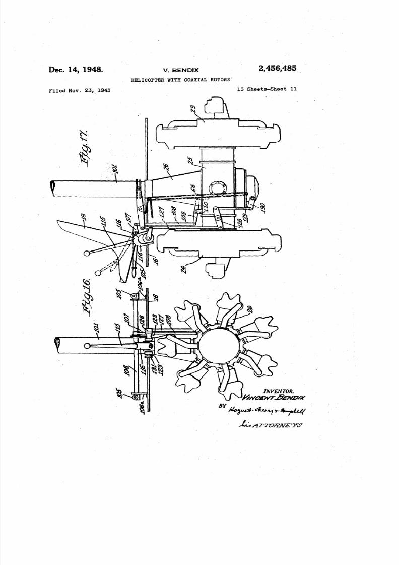
Figure 16 is a view in front elevation .illustrat-ing an engine and the control levers for control-ling the helicopter;Figure 17 is a side view illustrating the rela-
16 tionship between the control levers and the motorand transmission unit;Figure 18 is a top plan view of the motor and
transmission illustrating the connections between
the control levers and the operating mechanism20 for varying the positions of the propeller blades,
and varying the pitch of the Wings;Figure 19 is a view in front elevation of thegear box of one of the control levers;
Figure 20 is a view in cross-section taken on25 line 20-20 of Figure 19;
Figure 21 is a view in side elevation of the con-trol lever gear box illustrating the control leverpartly broken away; .
Figure 22 is a view in elevation of a portion of
30 the mechanism for attaining longitudinal pitchcontrol.
Figure 23 is a view in section taken on line23-23 of Figure 22.Figure 24 is a view in section taken on line
35 24-24 of Figure 22.
Figure 25 is a diagrammatic showing of the
control system for the rotary wings and propellerblades; and
Figure 26 is a view in side elevation of a modi-40 fled form of helicopter embodying the presentinvention.
The form of helicopter illustrated in F;gures I,2 and 3may consist of a fuselage, nacelle, or body10 of generally oval shape in front elevation and
45 in plan which consists largely of transparentpanels II of appropriate contour mounted in the
frames 12. As shown particularly in Figure 3, thebody 10 has a lower engine compartment 13 con-taining a framework 14 formed of steel tubing
liO or the like, shown in dotted lines, of generally
bridgework or triangulated structure. Above the
compartment 13 is a passenger compartment 15having a floor 16 upon whiCh are mounted pairsof oppositely facing seats 11 and 18. The body
5: 1 lOis generally symmetrical, affording visibility in
substantially all directions, thereby making thecabin particularly suitable for observation pur-poses.
The helicopter may be provided with landing(10gear of any desired type~ As illuatrated in Fig-ures 1, 2 and 3, the helicopter may be provided
With infiated pontoons 20 supported on outriggers
21 , on opposite sides of the body 10 which arejoined to the tubular frame 14 of the device.
n :; As illustrated in Figure 4a, landing gear wheels
22may be substituted for the pontoons 20, if de-
sired. The landing gear is conventional andforms no part of the present invention.
As shown in Figures 3 and 4a, a pair of radialiO engines 23 and 24 are supported in the frame 14
and have their respective crankshafts 23a and24a projecting inwardly in axial alignment into
a banjo type transmission gear box 25. The gearbox 25 is provided with an upwardly projecting
75 casing portion 26which acts to support and jour-

8/6/2019 Bendix Coaxial Rotor
http://slidepdf.com/reader/full/bendix-coaxial-rotor 19/26
~,466,48i. _, .. 8
na t a . number ot concentric shafts ~cluding the tating the rotors 21and 28. When a clutch intheshafts ~pon which the two rotors nand 28 are nature of a . friction clutch is provided, it maymounted. be manipulated to start the rotors and the starterAs best shownm Figure Sa, the gear box 2fl is Smay beomitted. Each engine may be equlpped
interposed between a tubular flanged member 29 5 Wltha starter.
which is bolted or otherwise secured to the motor As shown in Figure Sb, the upper end of the21and 8second s1m1la.rCYlindricalflanged mem- tubular drive shaft 48 is provided with a re-
bel' S @ which is secured to the motor l!4. At the ta.ln1ngflange portion ~ S a and a bearing retainerinner end of the member 211is secured a ring 4Gbsecured thereto which receives an anti-fric-gear S A having!!. rim portion interposed between 10 tion bearing l i S e engaging the shaft 42 so thatthe member 29 and a cup-shaped casing 22that these shafts are maintained in concentric re1a-forms a hous1ng for a reduction gear and forms tionship and are stiffened and strengthened byone end of the gear box 26. The reduction gear each other. The shaft 46 is further strengthenedincludes the ring gear 81, a plurality of planet and rigidified by means of the member 26 (Fig-gearsfl3 l'otatably mounted upon a . sleeve 34 and 15 ure 4a ) which Is provided at its upper end with·a sun gear ~3which includes a sleeve 3lia flxed anti-friction bearings 49 rotatably engaging the
to the drive shaft 230:for rotation thereWith. shaft 46.The sleeve 34 is concentric with the hub SSa of Below the flange 46 a is mounted the hub 10
a . bevel pinion 26 which is rotatably mounted on of the lower rotor 28. As best shown in Figuresthe sun gear sleeve 3l'ia by means of suitable needle 20 1and 2, the hub member 50 is of generally aero-or roller bearlngsln. The hub 3 6a forms with dynamic or oval crcss-secticn to reduce its Wind
the sleeve 8ti and suitable rollers 38 an overrun- resistance and is a parallelogram in plan. .Asning clutch permitting the pinion 36 to overrun shown in Figures 4b and 5b, the hub is of tubularthe sleeve 86a. The pinion 3Gis mounted In an or hollow construction and Is provided with ananti';'frictionbearing a s in the flange 320 ; of the 25 Internally threaded aperture 51 at its ·upper end
cup-shaped casing 32. With the construction de- which engages the threaded upper end of theSCribedthus far, rotation of the shaft 230 ; causes shaft 46. The hub li D ma.ybe locked to the shaftthe planet gears to roll upon the internal gear 31, ~6 by means of a suitable key. The flange 4S a iseffecting a reduction in speed of rotation of the bolted or otherwise secured to the hub 50. Thesleeve 3&and the pinion 36. 30 rotor hub lill is provided with a generally conicalThe pinion 36meshes with a pair of bevel gears casing member 52 secured to its upper surface
40 and t.llto cause them to rotate In opposite dl- which has an anti-friction bearing 53in its upperrections. The bevel gear 40is secured to a tubular end, bearing against and supporting the shaft
drive shaft 11i2which Is mounted in an antl-frtc- 42.tion bearing 43 in a detachable bottom section 44 35 The upper rotor :n is provided with a hub 54of the casing 2&. The upper bevel gear 41 is similar to the hub f iO of the rotor 28, but havingfixed to a tubular drive shaft 48 which is rotat- its end edges inclined oppositely to the end edgesablYmounted in anti-friction bearing 41in a de- of the rotor hub 50as shown particularly in Figuretachable section ti B at the upper end of the trans- 2 of the drawings. The hub 54 Is threaded onmission casing 25. Thus, upon operation of the 40"the upper end of the shaft 42.and is retaineddrive shaft 2 3a , the bevel gears 40 and 41 and· In fixed relatIonship to the shaft 42 by meansthe drive shaft 42and ~6 are rotated in opposite of a key and the sleeve 65 'which Is secured todirections and at reduced speed. the hub !i4.
The drive shaft Z4a Is connected to the ring The above-described assembly forms a verygears l iD and II! in exactly the same way as the 45 rigid and strong support for the wings and al-shaft 230 ; sothat when both of the motors 23and lows the rotor to be lightened considerably with-24are operating, their effects are exerted in the out loss of strength.
same direction to rotate the shafts 42 and' 46. Each of the rotors :n and 28, as illustrated, in-When one of the motors, for example, motor 23, eludes two wings, although more ..han two canis not operatlng or is disabled, the overrunning G O be provided if desired. The rotor 28 includes theclutch formed by the sleeves 34 and 3Sa and the hub 50 and the two wings :laa and 28b whichrollers 38 permits the motor 24 alone to drrve are of aero-dynamic cross-section, as best shownthe rotors in the same .dtrectton. If both of the in Figure 12of the drawings. That is, the wingsmotors 23and 21.lhould become inoperative, the 2 aa and : lOb are generally in the shape of an air-shafts 42 and ~6 can overrun and permit the 55 plane wing or air-ron. InasmUCh as the wingsrotors 28 and n, respecttvely, aIDxed thereto to 2 aa and 28b, as well as the wings 2 1 a and 21b ;windmill ann thus bring the helicopter to a safe are similar, only one of these wings wm be de- .landing: The free running characteristics of the scribed.
transmission make it possible to mount a starter As shown in Figures 5b, 10, 11 and 12, the
S (Figure 18>on the gear box 25 and to connect 60 W!<1g1lais provided with a tubular spar 5&whichthe starter to the gears 4D, tJ I by means of an extends substantially the length of the wing and
overrunnlngclutchand gear (not shown> or a con- is offset forwardly of the center line of the wing.
ventlonal starter clutch, thereby permitting the, The spar 56 extends radially from the axis of theinitiation of rotation of the rotors 21 and 28 be- shaft 42 and 46 and for that reason, the entirefore the engines 23and 24are started. 65 wing is offset slightly wIth respect to the axis of
The generator G for the engines 23 and 24 the shafts 42and 46, as shown in Figure 2. The
can also be geared to the transmission and spar 5&ts preferably formed of steel or othermounted on the gear box 25. ' strong material and is provided with a shank: por-
While overrunning clutches have 'been de- tion 5lia that is received in a roUer or needle bear-scribed,It wlll be understood ,that friction Or jaw 70 lng sleeve 51 of Circular cross-section that is
clutches may be substituted for the overrunning threaded Inthe outer end of the hub 50. An anti-
clutches or may be inserted between the motors friction thrust ,bearing 58 is disposed between the
23 and 24 and the overrunning clutches. The inner end of the sleeve 51and a shoulder 5Gbonfriction or jaw clutches have the. advantage of the spar and prevents the spar from moving out-
~rm!tt1ng the engines tobe operated without ro- 75 wardly under centrifugal force. The inner end

8/6/2019 Bendix Coaxial Rotor
http://slidepdf.com/reader/full/bendix-coaxial-rotor 20/26
9,458,4815
9of the spar 66 is received in a cylindrical socket Figure 12. The propeller blades 70 act as the
member 50a with needle bearings 69 interposed propulsion means for the deviceby rowing or re-therebetween to permit ready rotation of the spar acting against the air during the rotation of the56. rotors to force or move the helicopter generally
Each of the wings 28a. 28b, 21a, 2lb, is simi- 5 in a direction opposite to the direction of thrust
larly mounted in the hubs 60and 64with the lead- of the propeller blade. Thus, for forward :flight,ing edges of the wings facing in directions corre- the propeller or control blade 10 on the wing 2lbspondmg to the direction of rotation of the will be projected as this blade moves clockwise
rotors. from front to rear of the cabin 10, as viewed in
In order to vary the pitch of the wings to regu- 10 Figure 2, Whilethe propeller or control blade 70late the lifting characteristics of the device, each on the wing 28a will be projected as the rotor 28
of the spars 56, for example, that of the wing rotates in a counterclockwise direction from front2Sa, is provided with a pair of lugs 66c and 56d to rear of-the cabin 10, As rotation continuesprojecting inwardly from its inner end, as shown the propeller blade 70 on the wing 2la will be
in Figures 6, 7 and 8. The lugs 5 6c and 16dpass 16 projected as that wing traverses a clockwise arcthrough slots 46e and 46 d (Figure 5b) in the shaft from front to rear of the. body 10, while the46,these slots being arcuate about the axis of the propeller blade 10 on the wing 28b will be pro-spar, and are receivedin cam slots 60a and 60bof jected as the wing 28b traverses a counterclock-a sleeve 60, these slots being OPPOSitelyinclined wise arc from front to rear of the body 16.and symmetrical with respect to a common verti- 10 The propeller blades 10a!so are used to equal1ze
cal 11ne. The sleeve 60 is provided with axially the lifting effect of the wings. It willbeapparentextending slots 60efor receiving pins 461 · (Figure that while the helicopter is moving through the6) projecting inwardly from the drive shaft 46 air, the wings moving in the direction of flightso that the sleeve 60 rotates with the drive shaft will exert a greater 11ftthan the wings that are46. Inasmuch as the slots 60c are elongated, the 23 moving oppositely to the direction of flight.sleeve 60 can move axially of the drive shaft 46 When the propeller blades 10 are projected fromand in sodoing causes the spar 56to rotate about the wings, they act like flaps to increase theits longitudinal axis, thereby varying the pitch of 11ftof the wings. Thus, the projection of thethe wing 28a. propeller blade during rearward movement of aThe wing 2Sb is similarly connected to the 30 wing will increase the lift of the wing and offset,
sleeve60. The slots 60dand IDefor receiving the to a large extent, the loss of lift due to thespar lugs 5 6e and 56d are inclined in a direction motion of the helicopter. Inasmuch as the liftto cause the wings 2Saand 28b to rock in the op- exerted by the wings is substantially equalized,posite direction'to alter their pitch simultane- less flexing of the wings occurs and vibration isously and in the same sense. ; l 1 ' i correspondlng'v reduced.The wings 2la and 21b may be adjusted by . One type of mounting for the propeller blades
means of a sleeve 61 (Figures 5b and 9) similar '10 is 1llustrated in greater detail in Figures 10,to the sleeve 60, but of smaller diameter so that 11and 12of the drawings. Projecting rearwardlyit can be sl1dably received withtn and spl1nedto from the spar 56are a plurality of box-like mem-the drive shaft 42in the same manner as sleeve 40 bers 11 consisting of top and bottom plates lla60. and lIb of generally triangular shape which areThe sleeve 60 is secured to a tubular shaft 62 secured in spaced parallel relationship to the
which, as shown in Figure 5a, terminates between rear portion of the spar 56 in any suitable way,
the ends of the drive shafts 23a and 24a. such as, for example, by welding. As best shownThe pitch varying sleeve61is secured to a tubu- 45 in Figure 11, at the righthand end of the box-
Jar shaft 63 which terminates beneath the cap like member is a journal 12 comprising spacedmember 44 of the transmission. These shafts apart annular portions 72a and 12b in which is62 and 63have fixed on their lower extremities received a shaft 73 extending parallel with the
ring members 62a and 63a which are rotatably re- spar 66. The shaft 73is provided with a seriesceived within annular channels of rings 64' and 50 of brackets 74having forwardly projecting arms65, respectively. The rings U and 65, as shown 75 thereon, each arm carrying a roller 76. The
in Figure 5a, are connected by a shaft 66 having roller 76 is disposed between tracks 71c and 71doppositely threaded portions for receiving nuts on the plates 71a and 71b, respectively. Thethat engage the levers 64a and 65 a (Fig. 25) that brackets 74 are connected non-rotatably to the
are pivotally connected to the rings 64 and 65 so 55 shaft 13so that the shaft is capable of endwisethat upon rotation of the shaft the levers 64and movement, but cannot rotate. The shaft 73 is
65a are rocked in opposite directions. Endwise provided with a plurality of screw or helical gearsmovement of the shaft 66 moves the shafts 62 17 corresponding to the number of journalsand 63in unison. mounted on the spar 56. The gears 17 are re-
The shafts 62and 63may be shifted to vary the .60 ceived in internally threaded hubs 78 on rear-pitch of the wings in a manner and by a rnecha- wardly projecting arms 19 which form the ribs
nism to be described hereinafter. for the propeller blades 10. The ribs 79 are ofThe above-describedmechanism constitutes the skeleton formation, preferably having an upper
means for providing lift in a vertlcaj direction curved surface 19a, a fiat lower surface portionand for directional control. 05 19b and a forwardly curved portion 19c overIn order to propel the helicopter, propulsion which is secured a skin SOforming a cover for
means are provided which form a portion of the the propeller blade 10. The skin preferably. Is
rotor structure. formed of sheet metal in order to impart strengthAs shown in Figures 1and 2, each of the wings to the asembly, The exterior of the hub portion
21a, 2lb, 2Sa, and 211b is provided with one or 70 18 of the ribs 19 is provided with ball races 81
more fiapsl0, hereinafter referred to as a pro- and 82 which engage anti-friction journal and 'peller or control blade 70, The propeller or con- thrust bearings 83 mounted in the journal 12,trol blade 10 on each wing is movable between a thereby permitting easy pivoting of the propellerpositron within the section of the wing to a post- blade 10 within the journal while maintaining itnon projecting from the wing, as best shown in 75 against axial displacement,
10

8/6/2019 Bendix Coaxial Rotor
http://slidepdf.com/reader/full/bendix-coaxial-rotor 21/26
11The above-described construction provides a
mechanism whereby the propeller blade 10 maybe projected from and retracted within the sec-tion of the wing of the rotor 21 or 28. Endwisemovement of the shaft 13 toward the hub of 5
the rotor 21 or 28, as viewed in F'1gure11, willcause the propeller blade 10 to rock downwardlyto any desired position such as shown in Figure12,depending upon the distance that the shaft 13is moved. Outward movement of the shaft 13, 10as viewed in Figure 11, w1l1cause the propellerblade 10 to be retracted within the periphery ofthe wing. The above-described movements of theshaft 13 render the retraction of the propellerblades 10partially responsive to centrifugal force L'iso that more rapid action is obtained at higherrotor speeds. The shaft 13 is normally urgedoutwardly by centrifugal force, thereby tendingto rock the propeller blades 10 into retractedposition., .The mechanism for moving the shaft 13is dis-
closedmore particularly in Figures 4a, 4b, 5a, 5b,
13, 14 and 15. As shown in Figure 4b, the shaft13 extends inwardly to adjacent the end of thehub 50 or 54. The inner end of the shaft 13 isprovided with a flattened portion 85 (Figures 4b,
13,14 and 15) which is received between twopairsof rollers, 86,86 and 81, 81mounted on a bracket88 secured to the back of the spar 56. Therollers guide the endwise travel of the shaft 13and tend to prevent wobbling or buckling of theshaft. To allow for the pitch change of the wing,the link 84 is loosely pivotally connected at oneend to portion 85 and loosely pivotally connected
at the other end to a lever 89mounted pivotallyon the hub 50 and 54. A parallel shorter link
90 is also pivotally mounted on the hub 50 or 54.The lever 89and link 90 are. pivotally connectedto a bracket Sf having a bifurcated portion 91awithin which is received a cam-follower roller 92.The link construction will cause the axis of theroller 92 to remain substantiallY parallel withthe axis of the drive shafts 42 and 46. The camroller 92connected with each of the shafts 13ofthe wings 21a and 21b, for example, cooperates 4;;with a cam member 93 which is slidably axiallyof and rotatable relatively to the sleeve 55, anti-friction bearings 94being interposed between thecam member and sleeve.As shown in Figure 5b, the cam sleeve 93 is n o
provided with a conical cam lobe 93a on one side,normally on the same side of the fore and aft
axis as the wing which is retracting during for-ward movement of the craft. The cam 93 isillustrated as rotated 90° from ,the position nor- li;;
mally assumed for forward or reverse movementof the helicopter. Diametrically opposite the cam93a and at the upper end of the sleeve is anothershorter conical cam lobe 93b having the same in-
clination but reversed with respect to the lobe93a. 60
Cam lobe 93b is similar to cam lobe 93a, exceptof a height comparable with the desired reversespeed. With this arangement, as the rotor 21rotates, and with the cam sleeve 93 in the axialposition shown, the cam follower rollers 92on the 65wing 21a and on the wing 21b will merely rollaround a cylindrical portion of the sleeve 93be-
tween the cam lobes 93a and 93b. If the camsleeve 93 is moved upwardly so that the camrollers 92 engage a portion of the cam lobe 93a, 70
the cam follower roller 92 at the left hand sideof the device, as viewedinFigure 5b,willbemovedoutwardly slightly, thereby moving the shaft 13Inwardly and projecting the propeller blade 10out
of the section of the wing 21b . As the rotor Z1
2,408,486
12continues to rotate, the cam follower roller 92associated with the wing 21a will pass over thecam lobe raja and wlllproject the propeller blade1D carried by that wing.As the cam sleeve 93 is moved up further, for·
example, to maximum elevation, the cam followerroller 92 engaging the cam lobe 93a w11lbe de-flected outwardly a greater distance, therebyprojecting the propeller blade 10associated there-with farther from the Wing. In this way, the re-action of the propeller blade can be Varied inorder to control the speed or turning movementof the helicopter. Moreover, the' amount of liftof the wing can be varied considerably.The cam lobe 93b is ut1l1zedfor causing the
helicopter to move backwardly inasmuch as it ison the opposite side of the sleeve93from the camlobe 93a. Thus, when the 'cam follower roller 92engages the cam lobe 93b, the propeller blade 10
20 at the right-hand side of the arc of rotation, asviewed in Figure 5b, will be projected during
forward movement of the blade 0. e., with re-spect to the normally forward end of the body),causing the helicopter to move in the opposite
25 direction to what it is moved when the cam fol-lower roller 92 engages with the cam lobe 93a.
Usually it willbeunnecessary to provide springsor other additional mechanism for urging the camfollower roller 92 against the cam sleeve 93. As
30 described above, centrifugal force acts to movethe shaft 13 outwardly to retract the blade 10.Outward movement of the shaft 13 urges theroller 92 toward the cam sleeve 93. Moreover,the propeller blade 10Isaranged soas to be urged
3;; toward retracted position by the reaction of theair against its surface. These two forces arc
sufficient to cause the cam roller 92to follow thecontours of the cam sleeve 93under all operatingconditions.
40 The cam sleeve93is secured at its upper end toa cup-shaped member 95 which, in turn, is se-
cured to the upper end of a tubular shaft 96thatextends downwardly inside the pitch varying tube63and terminates beneath the transmission hous-ing 25. As shown in Figures 4a and 5a, the shaft96 is sl1dably and rotatably mounted in a cup-shaped casing 91 secured to the casing 25. Theend of the shaft 96 may be enclosed in a capmember 91b secured to the casing 91. The lowerend of the shaft 96 is provided with a flange 96a
that is received in the channel of a ring 99 bymeans of which the shaft 98can bemoved axially,
as w1ll be described presently.In addition to axial adjustment of the cam
sleeves 93 and 100, these sleeves maybe rotated
relatively to the shafts to vary the positions atwhich the propeller blades 10 are projected andretracted.As shown in Figures 5a, 22and 24,the shaft 96
is spl1ned to a worm gear 96b with capacity for
relative axial movement so that the shaft 96 canbe rotated by means of the worm 98 and shaft18ajournaled in the casing 91.
The cam follower rollers 92 on the rotor 28cooperate with a cam sleeve ID O similar to the
cam sleeve93and having cam lobes 100aand 100bthereon corresponding respectively to the cam
lobes 93a and 93b, but reversed end for end fromthe position of the corresponding cam lobes on
the sleeve93. Thus, when the cam follower roller92 associated with the wing 28a traverses the
cam lobe 100a, the propeller blade 10 w1l1be...projected from the wing 28a on the opposite side
of the shaft 46 from the propeller blade 10on the76 wing 2 1b . The cam sleeve 100 is mounted so

8/6/2019 Bendix Coaxial Rotor
http://slidepdf.com/reader/full/bendix-coaxial-rotor 22/26
13that upon downward movement, the extent ofprojection of the propeller blade 10 is increased.Upon upward movement of the cam sleeve I~O,areverse driving effect can be obtained by engage-
ment of the cam follower rollers 92 with the cam 6
lobe 100b .The cam sleeve 100 is mounted upon a sleeve
shaft 101 mounted externally of the drive shaft'46 and is sl1dably and rotatably received in anextension 102 at the upper end of the casing 10member 26 , as shown in Figure 4a. The shaft101 1s provided with a flange lO l a which is re-
ceived in the channel, of a ring 103 used for ad-justing the shaft 101 axially, as will be describedhereinafter. 15Within the extension 102 is a worm 102a
mounted on a shaft 102b that engages a wormgear 10 Ib that is slldably, but non-rotatablysplined to the shaft 101 (Figures 22 and 23).
Rotation of the worm 98 or 102a will cause ro- 20
tation of the corresponding shaft 96 or 10 I, there-by varying the position at. which the propeller
blades 10 carried by the rotors 2T and 28 areprojected. This construction also permits bal-ancing of the rotor torque, directional control and 25stabillzing of the helicopter as will be describedhereinafter.In order to control the operation of the hell-
copter, I have' provided a simplified control sys-
tem, shown diagrammatically in Figure 25 of the 30drawings, and in greater detail in Figures 16 to24. The control member for adjusting simulta-neously the pitch of the wings of the rotors 21and 28 and regulating the lift of the rotors isa lever IDSin the passenger compartment 15 of 3;;the body 10 . As shown in Figures 16, 17 and 18,actually two levers IDS may be used, one oneach side of the seats 18 so that an occupant ofeither seat can control the pitch of the wings.The levers 105 are connected by means of the 40shaft 106 sothat they move simultaneously. Theshaft 106 is supported in brackets 106a on thefioor 16and. has a nearly centrally located shortlever 101 which is connected by a link 108 to alever 109 which is supported on a fulcrum 110 45
projecttng upwardly from the transmission hous-ing 25. The inner end of the lever 109 is pro-vided with a sleeve 109a (Figs. 5a and 25) thatreceives the shaft 66 for rotation. Axial slid-ing movement of the shaft 66 and the sleeve 109a n ois prevented by means of the rings 66a fixed to
the shaft 66 on opposite sides of the sleeve 109a .Thus, upon downward or counterclockwise move-
ment of the pitch control lever lOS,the rod 66 ismoved downwardly, carrying the sleeves 60 and es61 therewith and rotating the wings 2la, 2lb,
28a and 28b to a neutral pitch position. In thisposition, the wings can windmill or spin freely
as the hellcopter descends while continuing torotate in the direction they are normally driven 60
by the engines 23 and/or 24 . As the pitch con-trol lever 105 is pulled upwardly in a clockwisedirection, the pitch of the wings of the rotors 21
and 28 changes toward a full positive pitch po-sition, as indicated in Figure 25, providing for G5
maximum lift.
The mechanism for controlling the speed andstability of the helicopter will now be described.
This mechanism includes a control lever or stick115 which is mounted for universal movement to
between the seats 18 , IBso as to be accessible tothe occupant of either seat. The stick 115has
a yoke 116 at its lower end, as best shown In Fig-ures 19 to 21. The yoke 116 has non-circularapertures 116a and 116b, in its opposite ends 75
:a,4lJ8,48lS
14which are adapted to receive the squared endsIll, 118 on the shaft 119 . The shaft 119 is ro-tatably mounted in a casing 120 formed of twosections 120a and 120b (Figure 21) which are
enlarged at one end to provide space for a bevelgear 121 on the shaft 119 . The casing sections120a and 120b are provided with split bearings120e and 12Dd for receiving the shaft 119 , asshown in FigUre20.
At right angles to the shaft 119 are disposeda pair of coaxial shafts 122 and 123 which aremounted in' split bearings 120e and 1201 in thecasing sections 120a and 120b . The inner endsof the shafts 122 and 123 are rotatably receivedin the socket portions 120g and 120h in the cas-ing 120 . The shaft 122 is provided with a seg-mental gear 124 which meshes with the gear 121and the shaft 123 is provided with a segmentalgear 125 , also meshing with the gear 121 . Withthe arrangement described above, when the lever
or stick 115 is rocked around the axis of theshafts 122 and 123 , these shafts also rotate withthe lever and the casing 120 . When the leveror stick I ISis rocked around the axis of theshaft 119 , the shafts 122 and 123 are rotated inopposite directions. The movements obtainedby controlled movement of the stick 115 are uti-lized to control the speed of the helicopter andtomaintain it in levelfiight.Referring now toFigure 25, the shafts 122 and
123 are received in suitable bearing supports inthe cabin of the helicopter to permit fore andaft rocking of the stick 1 IS, the casing 120 andthe shafts 122 and 123about the axis of the shafts122 and 123 . The shaft 122 is provided with alever 126fixed to its end, this lever being con-nected by means of a link In, a lever 128 pivot-ally mounted on part 3D , a link 129 and anotherlever 130 journaled in part 91b to the ring 99that is connected to the propeller control tube96 . Similarly, the shaft 123 is provided with alever 131 fixed thereto which is connected bymeans of a lever 132 pivotally mounted on part1 3 2 a to the ring 103 that engages the sleeveshaft101 . Thus, when the lever is pushed forward tothe dotted line position, identified as the "fullforward" position, the sleeve shaft j0I is moveddownwardly to a lower position, while the sleeveshaft 96 is moved upwardly to a higher position,thereby disposing higher portions of the cam lobes100 a , and 93 a in the path of the cam follower
rollers 92 on the rotors 21and 28.When the control stick 115is moved to the rearto the dotted line position, identified as full re-verse position, the cam sleeves 93 and 100 areshifted, to bring the reverse cam lobes 93b and100b into the path of rotation of the cam fol-lower rollers 92 .The 1inkages are such that upon equal rock-
ing of shafts 122 and 123 in opposite directions,tubes 96 and 101 are equally and oppositely dis-placed.
In order to compensate for or overcome tiltingof the helicopter about its longitudinal axis, the
stick 115 may be moved either to the right or
left. When the stick Is moved to the right, asviewed from the pilot's position, the shaft liS is
rocked counterclockwise, the lever 126 is movedclockwise, as viewed in Figure 25, and the lever
131 is moved counterclockwise, as viewed in.Fig-ure 25, thereby moving the shafts 96 and 101equally downwardly, As a result, the cam lobe100a is shifted to a position to cause the pro-peller blade associated therewith to exert a great-er reaction while the effect of the propeller blade
10 associated with the cam lobe Sia is either de-

8/6/2019 Bendix Coaxial Rotor
http://slidepdf.com/reader/full/bendix-coaxial-rotor 23/26
1,4158,0&81
15 16creased or the propeller blade Is projected by the end of a tiller bar liD fixed to the end of thecam lobe 91b. In the latter case, the propeller shaft II. The other end o t the t11lerbar liD Isblades 1Dact against each other on the same side connected by,a chain or cable III to a lever 148aof the body ID·and cause greatlY increased lift on the shaft . 4 . . The relationship of the foot
on the side at which they are projected. When 5 pedals to the shaft 68 Is such that when the leftthe stick III Is in neutral fore and aft pOSition, hand pedal .41a or 14Sa Is pushed forward themovement of the stick to the right will cause both clocitwfse rotating rotor 21 Is increased in pitchpropeller blades on the wings at the left hand side while the counterclockwise rotating rotor 28 Isof the cabin to be projected equallY,thereby t..lt- decreased in pitch. Due to torque reaction theing the cabin to the right or correcting for a 10 body IDof the helicopter Is rotated counterclock-tilt to the left. Similarly, tUts to the right can wise or to the left in the forward direction ofbe overcome by movmg the stick III to the .left. 1Ught. .Rotary movement of the cam sleeves 91aJ:!,dlDD The helicopter wlll also turn to the right when
is used to stabillZe he helicopter in a fore and the right hand pedal 141b or 14Gb Is depressed.aft direction or aoout the transverse axis. Thus, 15 From the preceding description of the controlsby adjusting the cam sleeves 93 and 100 to pro- of the helicopter disclosed herein, it w1l1be clearject the propeller blades on the rotors 21 and that e1Jectivecontroi of the helicopter about all28 simultaneously in the forward or rear arcs of . of the three axes of movement can be maintainedthe circle of rotation, an increased lift is given when the heliCOPteris in flight, Is hovering or isin that arc, thereby correcting for unbalance or 20 descending either freely or under power. More-
pitching about the transverse arcs. over, the helicopter can be turned or caused ,to .The mechanism for rotating the cam sleeves move in any desired direction with the engines
S~ and 10 0 Is shown more particularly in Figures not operatIng by contr.olling the action o t the22to 25. Each of the worm shafts 102b and 98a propeller blades 1Dand the pitch of the wings.
Is provided with a sprocket, 13 5 and 136 . respec- 2 1 1 This directional control, whUe the rotors aretively, over which is passed an endless chain In. s.utogyrating, provides a desirable safety factor
The shaft i02b Is provided with a second sprocket not obtainable with other aircraft.138 for receiving a chain 13 9 that has its ends As shown in Figure 26, the cabin of the hell-connected to a pitching control lever 140 on oppo- copter may be changed and rendered sim!la.r in 'site sides of the pivot 14 1 on which the lever 140 3 \J appearance and function to the fuselage of a con-is mounted. The worms 1 0 2 a and 98 are so ventional aeroplane. Thus, the cabin I G O may
formed that upon forward movement of the lever have a rounded nose portion I G I , having trans-140 , the shafts 96 and 101 are rotated In opposite parent panels extending from top to bottom, adirections to move the cam lobes 93 a and !1I0a passenger compartment I G 2 above the enginestoward the rear. As a result, the propeller blades 35 and around the drive shaft, an engine compart-70 are projected from the wings in the rear sec- ment 16 3 below the passenger compartment 16 2
tors of the circles of rotation and increased 11ft and a rearwardly extended tail portion !64 hav-is obtained in these sectors thereby tending to ing a rudder 165and an elevator 166. The ruddernose the helicopter down or to correct for rear- and elevator can be controlled in any desiredward pitch about the transverse axis. When the 40 way. for example, by means of the foot pedalspitching control1ever !.,tIDs pulled back, the cam and the pitching control stick 140, if desired.sleeves 9 3 and j 1 1 0 are rotated forwardly, thereby ':.i'heseelements can be used in conjunction withcausing the propeller blades if) to exert greater the rotors 21and 2.8and the propeller blades 10lift in the forward sectors or the arc. to control the direction of flight and the stabilityThe helicopter may be steered or turned by 4:5 of the helicopter. In flight for example, the
differentially varying the pitch of the blades of rudder can be used to steer the helicopter or tothe rotors 21 and 22. It wllI be apparent that offliet ally tendency of the helicopter to turn whenwhen the wings of one of the rotors have a greater eorrecttng for tilts and the elevator can be usedpitch than the wings of the other rotor a greater for correcting for pitching of the helicopter .mthrust results from the' rotor having the greater 50 conlunction with the propeller blades iO.
pitch. This unequal thrust tends to rotate the From the preceding description, it will be ap-
body III in a direction opposite to the direction parent that helicopters of the type disclosed aboveof rotation of the rotor having the greater thrust. have numerous advantages from the standpointAdvantage is taken of this action in the present of manufacture and use. All·of the controls, as
helicopter. 55 well as the operating elements, are centralizedAs described above, the shaft S6 has oppositely and form a . compact and extremely strong con-
threaded portions engaging the levers 64!a and structlon. Each of the various tubular shaftsl i5a so that rotation of the shaft will rock the making up the driving and control elements oflevers toward or away from each other, thereby .the helicopter tends to reinforce and strengthen
shifting the pitch control sleeves 60and 51in on- 60 the other elements against bending Or distortion.posite directions, thereby increasing the pitch of Therefore, these tubes may be made of a weIghtthe wings of one rotor and decreasing the pitch and size commensurate with the power that they
of the wing of the other rotor. Rotation of the are to transmit and need not be made so heavyshaft 66 is produced by means of two sets of foot as to render the entire assembly unwieldly andpedals 1 45 a, !~1 :ib and i4Ga and 14lib (Figures 65 of low load-carrying capacity.
·18and 25). The provision of overrunning clutches betweenThe pedals j i l 1 J a and 146a are connected by the engines and the rotors makes for increased
means of a . shaft In and the pedals 145b and safety inasmuch as the rotors 21 and 28 can be146b are connected by means of the shaft 148. drIven by one or both of the engines or can spin
The shafts In and S48 are suitably Journaled in 70 freely if both engines stop, Moreover, increasedbearings in the floor !6 o f the body 10. Thus the ease of starting can be accomplished by means of
pedals Ai lSa and Il;!l:lamove together while the the starter which spins the rotors 21and 28beforepedals 145band Ullib move together. the engines are started, thereby relievIng them ofThe shaft31rilis provided with an arm 141a starting load.
that is connected by a , chatn or cable •4 9 to one 70 A particUlar adv~ntage of the power ana trans ..

8/6/2019 Bendix Coaxial Rotor
http://slidepdf.com/reader/full/bendix-coaxial-rotor 24/26
2,468,486
17 18mission assembly described above is that a very drive shafts, each cam member having an axiallylow center of gravity can be obtained by locating tapered cam lobe, cam follower means carried bythe engines and transmission on the lower end of said rotors and engaging said cam members for
the drive shaft in spaced relationship to the moving said propeller blades between said post-planes of the rotors. In addition, it is most ad- .6 tions in proportion to deflection of said cam fol-vantageous to have the engines below, from the lower means by said cam lobes, means intercon-standpoint of safety, rather than above, the pas- nectIng said cam follower means and said blades,senser compartment. tubular shafts concentric with said drive shaftsIt will be understood, of course, that the con- fixed to said cam members, and unitary control
troIs for varying the pitch of the wingS and for 10 means for moving said last mentioned tubularcontrolling the operation of the propeller blades shafts selectively with relation to said drive1D can be modified considerably and that other shafts.mechanical equivalents than the mechanically 5. In a helicopter, the combination of a pair ofmovable tubular shafts may be used instead. concentric, tubular drive shafts, means for rotat-Thus, hydraulic or electrical power transmitting 15 ing said shafts in opposite directions, an uppersystems may be substituted for the mechanical rotor fiXedto one of said drive shafts, a lowersystem disclosed herein without departing from rotor fixed to the other drive shaft, each rotorthe invention. Also,irreversible connections may having at least. two wings, a propeller blade onbe provided between the control sticks ID5, 115, each wing movable -from a position in said wingand 140 and their associated mechanisms so that 20 to a position projecting from said wing, a thirdthey can be adjusted and will remain in adjusted shaft within said drive shafts, a cam member onpositions. Moreover, the shape and size of the said third shaft adjacent to the uppermost rotor,rotors may be modified, depending upon the size an axially tapered cam lobe on said cam mem-and load-carrying capacity of the helicopter andber, cam follower means engaging said camthe position of the propeller blades may bealtered 25 member for projecting' said propeller blades onto ut1l1zethe power of the engines most effective- said upper wings upon engagement with saidly, in propelling and stab1l1zingthe device. cam lobe, a fourth tubular shaft concentricAccordingly, it should be understood that the with and outside said drive shafts, a second cam
above-described embodiments of the invention member fixed to said fourth shaft and hav-are illustrative and should not be regarded as 30 ing an axially tapered cam lobe thereon inlimiting the scope of the following claims. angularly spaced relation to the lobeon said thirdI claim: shaft cam member, cam follower means on the1. In a helicopter, the combination of a pair of lower rotor engageable with said second cam
eccentric counter-rotatable drive shafts, a rotor member for projecting the propeller blades on the
mounted on each drive shaft, each rotor having 35 lower wings, and means for selectively adjustinga plurality of' variable pitch wings, means for said third and fourth shafts axially in the samevarying the pitch of the wings of said rotors se- or in opposite directions.lectively in the same or in the opposite sense, a 6. In a hellcopter, the combination of a pairpropeller blade extending longitudinally of each of counter-rotatable rotors having at least twowing, and means for intermittently projecting 40 variable pitch wings, control blades movablyand retracting said propeller blade with respect mounted in said wings, separate, concentric,to said wing. counter-rotatable drive shafts supporting satd ro-2. In a helicopter, the combination of a pair of tors, pitch control shafts concentric with the
counter-rotating rotors. each having a plurallty drive shafts and rotatable therewith for varyingof wings with longitudinally mounted movable 45 the pitch of said wings, operative connectionsblades, a plurality of vertical, concentric shafts between the wings and said pitch control shafts,comprlstng shafts for driving said rotors and con- a screw-threaded member mounted for axialtrol shafts movable relative to said drive shafts movement and non-rotatable relatively to eachfor changing the pitch of said wings and for mov- wing, means having screw-threaded engagement
Ing the blades attached to said wings and op- G O with said axially movable member for intermit-erative connections between said wingS and tently moving the control blades and meant; con-blades and said control shafts. centric with thedrrve shafts for intermittently3. In a helicopter, the combinatton of a pair moving said screw-threaded member to actuate
of counter-rotating rotors each having a plurality said control blades.of wings, control blades extending longitudinally 66 7. In a helicopter, the combination of a pairof and movable relatively to said wings and a of concentric, tubular drive shafts, means forplurality of vertical, concentric shafts compris- rotating said shafts in opposite directions, a rotoring shafts for' driving said rotors, and control having at least two variable pitch wings fixedshafts movable relative to said drive shafts for at its midportion to each drive shaft for rotationchanging the pitch of said wings, and for moving 60 therewith, means for varying the pitch of saidthe control blades, for the purpose of elevating, wings, a propeller blade adjacent the end of eachlowering and laterally moving said helicopter, and rotor wing movatle from a retracted positionfor controlling the stabilizing of the helicopter substantially within the periphery of said wingand operative connections between said wings toa position projecting from said wing. means
and blades and said control shafts. 66 for projecting and retracting said propeller blades4. In a helicopter, the combination of a pair of of one of said rotors as they traverse an arc onconcentric tubular drive shafts, means for rotat- one side of said drive shafts, means for protect-ing said drive shafts in OPPOSitedirections, a ing and retracting the propeller blades, on therotor fixed to each of said shafts, each rotor hav- other rotor as they traverse an arc em the op-ing at least two substantially radially extending 70 posfte side of: said drive shafts, and means forwings, a propeller blade carried by and extending shifting said arcs relative to one another. ,longitudinally of each wing and movable between 8. In a helicopter, the combination of a paira position in the wing and a posttton projecting ,of concentric tubular drive shafts, means forfrom said wing blade, a pair of cam members rotating said shafts in opposite directions, aspaced apart axially of and concentric with said 76 rotor fixed to each drive shaft for rotation there-

8/6/2019 Bendix Coaxial Rotor
http://slidepdf.com/reader/full/bendix-coaxial-rotor 25/26
19'with, each rotor having at least two variablepitch substantially radially extending wings,means for varying the pitch of the wings of each
rotor simultaneously, means for varying the pitchof the wings of one of said rotors relatively tothe pitch of the wings of the other rotor, a pro-peller blade extending longitudinally of each {Ifsaid rotor wings and movable between a positionin said wing blade and a position projecting fromthe wing blade, and means for moving the pro-peller blades between said positions intermit-tently. '9. In a helicopter, the combination of a pair of
concentric, tubular drive shafts, means for rotat-ing said shafts in opposite directions, a variablepitch rotor fixed at its midportion to each driveshaft for rotation therewith, means for varyingthe pitch of said rotors selectively in the same orin the opposite senses, a propeller blade ad-jacent to each end of each rotor movable froma retracted position substantially within theperiphery of said rotor to a position projectingfrom said rotor, spaced cam members adjacentto said rotors for projecting and retracting saidpropeller blades on said rotors, means connectedto said propeller blades and engaging said cammembers and means for adjusting said cams tovary the extent of projection of said propellerblades.10. In a helicopter, the combination of a pair
of concentric, tubular drive shafts, means for ro-tating said shafts in opposite directions, a vari-able pitch rotor fixed at its midportion to eachdrive shaft for rotation therewith, cam means
for varying the pitch of said rotors selectively inthe same or in opposite directions, a propellercontrol blade adjacent to each end of each rotormovable from a retracted position substantiallywithin the periphery of said wing to a positionprojecting from said wing, spaced cam membersadjacent tosaid rotors for projecting and retract-ing said control blades, cam followers operativelyconnected with said control blades and adaptedto engage said cam members, and shafts con-centric with said drive shafts for adjusting saidcams to vary the extent of projection of saidpropeller blades.11. In a helicopter, the combination of a
frame, at least one engine supported in saidframe, a transmission adjacent to said enginehaving a casing and a pair of gears connectedto said engine, for rotation at equal speed inopposite directions, a passenger compartmentabove said engine, a first tubular drive shaftJournaled in said casing and extending upwardlythrough said compartment and connected to oneof said gears, a second tubular drive shaft con-centric with said first shaft and connected tothe other gear, a variable-pitch multiple wingrotor fixed to each of said shafts, control bladesadjacent to the ends of said wings projectablefrom and retractable into said wings,controlshafts concentric with said tubular drive shaftsfor varying the pitch of the wings of said rotorsand for controlling the movements of said con-
trol blades and operative connections betweensaid rotor wings and control blades and said con-trol shafts.
12. In a helicopter, the subcombinatton of a ro-tary drive shaft, a hub fixed thereon having aplurality of substantially radially extending sock-ets, an elongated wing of aerodynamic cross-sec-tion rotatably mounted in each socket to permitvariation of the pitch of the wing, an axiallyshiftable member concentric and rotatable with
2,466,485
20said shaft, having cam surfaces engageable withthe wings for varying the pitch of said wings,means for shifting said member axially to vary
the pitch of said wings, control blades adjacentIS the outer ends of said wings and forming a por-tion of the periphery of said wings, means sup-porting said control blades for relative movementto a position projecting from the wings, and rela-tively movable cam means concentric with said
10 shaft for moving said control blades intermit-tently and cam followers operatively connectedwith said control blades and adapted to engagesaid cammeans.13. In a helicopter, the subcombmatton of a
15 tubular drive shaft, a hub fixed to said shaft hav-ing a plurality of substantially radially extendingsockets, an elongated wing for each socket, saidwing having a tubular spar, one end of which isrotatably mounted in a socket to permit varia-
20 tion of the pitCh of said wing, a cam memberconcentric and rotatable with and shiftable axi-ally of said drive shaft having inclined cam slotstherein, means on said wing spars extending intosaid cam slots, means for shifting said cam mem-
25 ber axially to vary the pitch of said wings, pro-peller blades pivotally mounted on each wing andmovable about an axis extending longitudinallyof said wing from a position in said wing to aposition projecting at an angle to the periphery
30 of said wing, and means for moving said propellerblades intermittently.14. In a helicopter, the subcombination 'of a
tubular drive shaft, a hub fixed to said shafthaving a plurality of substantially radially ex-
35 tending sockets, an elongated wing for eachsocket, each wing having a tubular spar, one endof which is rotatably mounted in a socket topermit variation of the prtch of said wing, a cam,member concentric with, non-rotatable relatively
40 to, and shiftable axially of said drive shaft hav-ing inclined cam slots therein, means on saidwing spars extending into said cam slots, meansfor shifting said cam member axially to vary thepitch of said wings, propeller blades pivotally
4li mounted on each wing and movable about an axisextending longitudinally of said wing to a positionprojecting at an angle to the periphery of saidwing, means for actuating said propeller blades,and cam means engaging said last-named
50 means, said cam means being concentric withsaid drive shaft and shiftable axially relativelythereto for 'moving said propeller blades inter-mittently.15. In a helicopter, the combination of a pair
55 of rotatable, concentric tubular drive shafts, avariable pitch, multiple wing rotor fixed to eachof said shafts adjacent one end thereof, meansat the other ends of said shafts for rotating themin opposite directions, separate tubular sleeves
60 concentric with said drive shafts, means engag-ing said sleeves and connected to the wings ofsaid rotors for varying the pitch of said wings,a control lever connected to said sleeves for shift-ing them tovary the pitch of saidwings, propeller
65 blades mounted on said wings for movement be-
tween a retracted position and a prolected po-sttton outside saidwings,separate cams concentric
with said drive shafts and adjustable axially ofsaid drive shafts, means engaging said cams and
70 connected to said propeller blades for intermit-tently projecting said propeller blades to varying
extents and retracting said propeller blades, tu-bular members concentric with said driveshaftsfixed to said cams and adjustable axially of said
75 shafts, and a universally movable lever connected

8/6/2019 Bendix Coaxial Rotor
http://slidepdf.com/reader/full/bendix-coaxial-rotor 26/26
21to said members for moving said members si-multaneously iIithe same direction and simul-taneously in opposite directions ..16. In a helleopter, the combination of a pair.
of rotatable, concentric tubular driveshafts, a Ii
variable pitch multiple wing rotor nxed'to eachof said shafts adjacent one' end thereof, meansat the other ends of said shafts for rotating themin opposite directions, propeller blades mountedon the wing blades of said rotors for movement 10
between a retracted position within the periph-eries of said wing blades and a projectedposition outside said peripheries, separate camsconcentric with said .driveshafts, means engagingsaid cams and connected to said propeller blades };)and adjustable axially of said driveshafts forintermittently projecting to varying extents andretracting said propeller blades, shaft membersconcentric with said driveshafts fixed to said camsand adjustable axially of said. shafts, and a 20
universally movable lever connected to said mem-bers for moving said members simultaneously inthe same direction and simultaneously in oPpositedirections.17. In I . l. helicopter, the combination of a pair
of vertical tubular, concentric driveshafts, a mul-tiple wing rotor fixed adjacent the upper end ofeach of said drlveshafts for rotation therewith,means adjacent to the lower end of said drive-shafts for rotating said shafts in opposite direc-tions, a propeller blade adjacent the outer end ofeach motor wing movable to a position projectingfrom the blades, a cam member having an axiallytapering lobe adjacent each rotor concentric withand disposed outside the corresponding tubular
shaft, means connected to said propeller bladesand engageable with said cam member to projectsaid propeller blades intermittently, tubularsleeves concentric with said shafts fixed to saidcam members, a control lever movable about tworight angularly related axes, and means connect-ing said lever to said tubular sleeves to move saidsleeves relatively axially upon movement of saidlever about one of said axes, and move said sleevesequally and in the same direction upon move-ment of the lever about the other axis.18. The combination set forth In claim 17 in
which the means connecting the lever to saidsleeves comprises a casing having a . first shafttherein connected to said lever, a gear on saidshaft, second and third aligned shafts projecting
into said casing from opposite Sides ata rightangle· to the first shaft, gears on said second andthird shafts meshing with the gear on the firstshaft, and levers 011 said second and third shafts 66
connected to di1rerent sleeves.19. In a helicopter, the combination of a pair
8,4156,4815
22of concentric driveshafts, a multiple wing, varia-ble pitch rotor fixed to each driveshaft, meansfor rotating said driveshafts in opposite direc-tions, a first pitch varying shaft concentric androtatable with and shiftable axially of one of
said driveshafts, a second pitch varying shaftconcentric and rotatable with, and shiftable axi-ally of, the other driveshaft, means engagingsaid pitch varying shafts and connected to thewings of said rotors, means for shifting said pitchvarying shafts simultaneously in the same axialdirection for varying the pitch of the wings inthe same sense, and means for shifting the pitchvarying shafts axially in opposite directions tovary the pitch of the wings of one rotor relativelyand in the opposite sense to the pitch of the wingsof the other rotor.
. VINCENT BENDIX.
REFERENCES CITED
The following. references are of record in thefile of this patent:
UNITED STATES PATENTS
Name DateLister Jan. 20, 1914Perry July 16, 1918
Perry June 29, 1920Hewitt Aug. 24, 1920
Pescara _-' Jan. 17, 1922Pescara Mar. 20, 1923Pescara July 14, 1925
MacNeil July 13, 1926Smith Dec. IS, 1931Ludlow July 26, 1932
Gillis et al. Dec. 20, 1932Goldman Feb. 'I, 1933
Breguet July 18, 1933Wick Dec. 5, 1933
Breguet et al. Jan. I, 1935Dormer Dec. 10, 1935Ware J a n . 21. 1941
Upson Feb. 18. 1941Lloyd Feb. 25• . 1941Bennett Jan. 27. 1942Nalllgner Dec. 15, 1942Barling Jan. 19, 1943Michelis Feb. 9, 1943Jensen Aug. 'I, 1945Wales Sept. 23, 194 '1
FOREIGN PATENTS
25 N!JlIlber1,084,8061,272,8461,345,1011,350,456
30 1,403,6241,449,1291,546,3131,592,7401,836,406
35 1,869,326
1,891,3841,896,5111,919,0891,938,091
40 1,896,7092,023,7602,229,1532,232,289
45 2,232,6832,271,4732,305,4542,308,8022,310,2202,381,596
50 2,427,936
Number125,202610,434695,918
Country :pateGermany Nov. 22. 1901Germany Mar. 12. 1936Germany sept. 5, 1940


