
IMPLEMENTATION GUIDE
Copyright © 2013, Juniper Networks, Inc. 1
Best PraCtICe GuIdelINes for dePloyING eX8200 VIrtual ChassIs CoNfIGuratIoNs
although Juniper Networks has attempted to provide accurate information in this guide, Juniper Networks does not warrant or guarantee the accuracy of the information provided herein. third party product descriptions and related technical details provided in this document are for information purposes only and such products are not supported by Juniper Networks. all information provided in this guide is provided “as is”, with all faults, and without warranty of any kind, either expressed or implied or statutory. Juniper Networks and its suppliers hereby disclaim all warranties related to this guide and the information contained herein, whether expressed or implied of statutory including, without limitation, those of merchantability, fitness for a particular purpose and noninfringement, or arising from a course of dealing, usage, or trade practice.

2 Copyright © 2013, Juniper Networks, Inc.
IMPLEMENTATION GUIDE - Best Practice Guidelines for Deploying EX8200 Virtual Chassis Configurations
Table of Contents
Introduction . . . . . . . . . . . . . . . . . . . . . . . . . . . . . . . . . . . . . . . . . . . . . . . . . . . . . . . . . . . . . . . . . . . . . . . . . . . . . . . . . . . . . . . . . . . . . . . . . . . . . 4
scope . . . . . . . . . . . . . . . . . . . . . . . . . . . . . . . . . . . . . . . . . . . . . . . . . . . . . . . . . . . . . . . . . . . . . . . . . . . . . . . . . . . . . . . . . . . . . . . . . . . . . . . . . . 4
terminology . . . . . . . . . . . . . . . . . . . . . . . . . . . . . . . . . . . . . . . . . . . . . . . . . . . . . . . . . . . . . . . . . . . . . . . . . . . . . . . . . . . . . . . . . . . . . . . . . . 4
design Considerations . . . . . . . . . . . . . . . . . . . . . . . . . . . . . . . . . . . . . . . . . . . . . . . . . . . . . . . . . . . . . . . . . . . . . . . . . . . . . . . . . . . . . . . . . . . 4
eX8200 Virtual Chassis Configurations . . . . . . . . . . . . . . . . . . . . . . . . . . . . . . . . . . . . . . . . . . . . . . . . . . . . . . . . . . . . . . . . . . . . . . . . . 4
eX8200 Virtual Chassis Ports . . . . . . . . . . . . . . . . . . . . . . . . . . . . . . . . . . . . . . . . . . . . . . . . . . . . . . . . . . . . . . . . . . . . . . . . . . . . . . . . . . 5
Virtual Chassis Ports on the Xre200 external routing engine . . . . . . . . . . . . . . . . . . . . . . . . . . . . . . . . . . . . . . . . . . . . . . . . . . . . 5
Virtual Chassis Ports on eX8200 Member Chassis . . . . . . . . . . . . . . . . . . . . . . . . . . . . . . . . . . . . . . . . . . . . . . . . . . . . . . . . . . . . . . 5
Comparison Between eX4200 and eX8200 Virtual Chassis Configurations . . . . . . . . . . . . . . . . . . . . . . . . . . . . . . . . . . . . . . . 6
eX8200 Virtual Chassis high availability and resiliency . . . . . . . . . . . . . . . . . . . . . . . . . . . . . . . . . . . . . . . . . . . . . . . . . . . . . . . . . . . .7
hardware redundancy . . . . . . . . . . . . . . . . . . . . . . . . . . . . . . . . . . . . . . . . . . . . . . . . . . . . . . . . . . . . . . . . . . . . . . . . . . . . . . . . . . . . . . . . .7
Control Plane redundancy . . . . . . . . . . . . . . . . . . . . . . . . . . . . . . . . . . . . . . . . . . . . . . . . . . . . . . . . . . . . . . . . . . . . . . . . . . . . . . . . . . . . . 8
Graceful routing engine switchover . . . . . . . . . . . . . . . . . . . . . . . . . . . . . . . . . . . . . . . . . . . . . . . . . . . . . . . . . . . . . . . . . . . . . . . . . . 8
Nonstop active routing . . . . . . . . . . . . . . . . . . . . . . . . . . . . . . . . . . . . . . . . . . . . . . . . . . . . . . . . . . . . . . . . . . . . . . . . . . . . . . . . . . . . . 8
data Plane redundancy . . . . . . . . . . . . . . . . . . . . . . . . . . . . . . . . . . . . . . . . . . . . . . . . . . . . . . . . . . . . . . . . . . . . . . . . . . . . . . . . . . . . . . . 8
Nonstop software upgrade (Nssu) . . . . . . . . . . . . . . . . . . . . . . . . . . . . . . . . . . . . . . . . . . . . . . . . . . . . . . . . . . . . . . . . . . . . . . . . . . . . 8
the Makeup of an eX8200 Virtual Chassis . . . . . . . . . . . . . . . . . . . . . . . . . . . . . . . . . . . . . . . . . . . . . . . . . . . . . . . . . . . . . . . . . . . . . . . 9
Xre200 external routing engines . . . . . . . . . . . . . . . . . . . . . . . . . . . . . . . . . . . . . . . . . . . . . . . . . . . . . . . . . . . . . . . . . . . . . . . . . . . . . . 9
eX8200 Chassis . . . . . . . . . . . . . . . . . . . . . . . . . . . . . . . . . . . . . . . . . . . . . . . . . . . . . . . . . . . . . . . . . . . . . . . . . . . . . . . . . . . . . . . . . . . . . . 9
Member Id and Interface Numbering . . . . . . . . . . . . . . . . . . . . . . . . . . . . . . . . . . . . . . . . . . . . . . . . . . . . . . . . . . . . . . . . . . . . . . . . . . . 9
Network Ports . . . . . . . . . . . . . . . . . . . . . . . . . . . . . . . . . . . . . . . . . . . . . . . . . . . . . . . . . . . . . . . . . . . . . . . . . . . . . . . . . . . . . . . . . . . . . . . . . 9
Virtual Chassis Ports . . . . . . . . . . . . . . . . . . . . . . . . . . . . . . . . . . . . . . . . . . . . . . . . . . . . . . . . . . . . . . . . . . . . . . . . . . . . . . . . . . . . . . . . . .10
Connecting an Xre200 into an eX8200 Virtual Chassis Configuration . . . . . . . . . . . . . . . . . . . . . . . . . . . . . . . . . . . . . . . . . . . .10
Building Virtual Chassis Configurations over long distances . . . . . . . . . . . . . . . . . . . . . . . . . . . . . . . . . . . . . . . . . . . . . . . . . . . . . . .10
New eX8200 Virtual Chassis Configuration steps . . . . . . . . . . . . . . . . . . . . . . . . . . . . . . . . . . . . . . . . . . . . . . . . . . . . . . . . . . . . . . . . . 11
upgrade all Xre200s and eX8200 switches to the same Version . . . . . . . . . . . . . . . . . . . . . . . . . . . . . . . . . . . . . . . . . . . . . . . 11
Prepare eX8200 switches to be Part of a Virtual Chassis Configuration . . . . . . . . . . . . . . . . . . . . . . . . . . . . . . . . . . . . . . . . . . 12
Create Preprovisioned Virtual Chassis Configuration on Master Xre200 . . . . . . . . . . . . . . . . . . . . . . . . . . . . . . . . . . . . . . . . . . 12
Connect the eX8200 switches to the Xre200s . . . . . . . . . . . . . . . . . . . . . . . . . . . . . . . . . . . . . . . . . . . . . . . . . . . . . . . . . . . . . . . . . 13
Interconnect the Xre200s . . . . . . . . . . . . . . . . . . . . . . . . . . . . . . . . . . . . . . . . . . . . . . . . . . . . . . . . . . . . . . . . . . . . . . . . . . . . . . . . . . . . . 13
Convert eX8200 switch 10Gbe Network Ports to Virtual Chassis Ports . . . . . . . . . . . . . . . . . . . . . . . . . . . . . . . . . . . . . . . . . . . 13
Interconnect the eX8200 switches via the Converted 10Gbe Virtual Chassis Ports . . . . . . . . . . . . . . . . . . . . . . . . . . . . . . . . 13
Virtual Chassis show Commands . . . . . . . . . . . . . . . . . . . . . . . . . . . . . . . . . . . . . . . . . . . . . . . . . . . . . . . . . . . . . . . . . . . . . . . . . . . . . . 13
Migrating eX8200 standalone switches to eX8200 Virtual Chassis Configurations . . . . . . . . . . . . . . . . . . . . . . . . . . . . . . . . .16
upgrade the switches to Junos os Version 11.1 . . . . . . . . . . . . . . . . . . . . . . . . . . . . . . . . . . . . . . . . . . . . . . . . . . . . . . . . . . . . . . . . . . 17
revert the access switch links Back to the first eX8208, Now in Virtual Chassis Mode . . . . . . . . . . . . . . . . . . . . . . . . . . . .19
attach the second eX8208 to the Pair of Xre200s and Configure It in Virtual Chassis Mode . . . . . . . . . . . . . . . . . . . . . 20
restore the access switch links Back to the second eX8208, Now in Virtual Chassis Mode . . . . . . . . . . . . . . . . . . . . . . . 21
disable VrrP on the eX8200 switches, Now in Virtual Chassis Mode . . . . . . . . . . . . . . . . . . . . . . . . . . . . . . . . . . . . . . . . . . . 22
Copyright © 2013, Juniper Networks, Inc. 3
IMPLEMENTATION GUIDE - Best Practice Guidelines for Deploying EX8200 Virtual Chassis Configurations
eX8200 Virtual Chassis high availability Best Practices . . . . . . . . . . . . . . . . . . . . . . . . . . . . . . . . . . . . . . . . . . . . . . . . . . . . . . . . . . 23
eX8200 Virtual Chassis failover Convergence times . . . . . . . . . . . . . . . . . . . . . . . . . . . . . . . . . . . . . . . . . . . . . . . . . . . . . . . . . . . . . 24
eX8200 Virtual Chassis over long distances Configuration steps . . . . . . . . . . . . . . . . . . . . . . . . . . . . . . . . . . . . . . . . . . . . . . . . . 25
Physical Connections of Xre200s and Intermediate switches . . . . . . . . . . . . . . . . . . . . . . . . . . . . . . . . . . . . . . . . . . . . . . . . . . 25
ufd Configuration on Intermediate switches . . . . . . . . . . . . . . . . . . . . . . . . . . . . . . . . . . . . . . . . . . . . . . . . . . . . . . . . . . . . . . . . . . 25
Xre200 Configuration . . . . . . . . . . . . . . . . . . . . . . . . . . . . . . . . . . . . . . . . . . . . . . . . . . . . . . . . . . . . . . . . . . . . . . . . . . . . . . . . . . . . . . . . 27
Conclusion . . . . . . . . . . . . . . . . . . . . . . . . . . . . . . . . . . . . . . . . . . . . . . . . . . . . . . . . . . . . . . . . . . . . . . . . . . . . . . . . . . . . . . . . . . . . . . . . . . . . . 28
about Juniper Networks . . . . . . . . . . . . . . . . . . . . . . . . . . . . . . . . . . . . . . . . . . . . . . . . . . . . . . . . . . . . . . . . . . . . . . . . . . . . . . . . . . . . . . . . . 28
Table of Figures
figure 1: eX8200 Virtual Chassis configuration with Xre200 connecting to every member . . . . . . . . . . . . . . . . . . . . . . . . . . 5
figure 2: eX8200 four-member Virtual Chassis configuration with full mesh connection
between every access switch and line card chassis. . . . . . . . . . . . . . . . . . . . . . . . . . . . . . . . . . . . . . . . . . . . . . . . . . . . . . . 6
figure 3: two-member eX8200 Virtual Chassis with Xre200s connected to each other
directly over a Gbe interface. . . . . . . . . . . . . . . . . . . . . . . . . . . . . . . . . . . . . . . . . . . . . . . . . . . . . . . . . . . . . . . . . . . . . . . . . . . . .10
figure 4: two-member eX8200 Virtual Chassis over long distance . . . . . . . . . . . . . . . . . . . . . . . . . . . . . . . . . . . . . . . . . . . . . . . . 11
figure 5: redundant pair of eX8200 running VrrP and rtG with all traffic flowing
over master eX8200 switch . . . . . . . . . . . . . . . . . . . . . . . . . . . . . . . . . . . . . . . . . . . . . . . . . . . . . . . . . . . . . . . . . . . . . . . . . . . . .16
figure 6: all traffic flows through the backup eX8200 switch while master is being
prepared to run eX8200 Virtual Chassis configuration . . . . . . . . . . . . . . . . . . . . . . . . . . . . . . . . . . . . . . . . . . . . . . . . . . . . 17
figure 7: single-member eX8200 Virtual Chassis is formed while all traffic flows
through the backup eX8200 . . . . . . . . . . . . . . . . . . . . . . . . . . . . . . . . . . . . . . . . . . . . . . . . . . . . . . . . . . . . . . . . . . . . . . . . . . . .18
figure 8: all traffic is migrated from backup eX8200 to the single-member eX8200 Virtual Chassis . . . . . . . . . . . . . . . . .19
figure 9: all traffic flows through single-member eX8200 Virtual Chassis while backup eX8200 is configured to join
eX8200 Virtual Chassis configuration . . . . . . . . . . . . . . . . . . . . . . . . . . . . . . . . . . . . . . . . . . . . . . . . . . . . . . . . . . . . . . . . . . 20
figure 10: traffic is load-balanced over both eX8200 switches migrated to two-member eX8200 Virtual Chassis . . . . 21
figure 11: logical network topology of eX8200 Virtual Chassis configuration . . . . . . . . . . . . . . . . . . . . . . . . . . . . . . . . . . . . . . . 22
figure 12: two-member eX8200 Virtual Chassis with dual-homed access devices. . . . . . . . . . . . . . . . . . . . . . . . . . . . . . . . . . 23
figure 13: a pair of two-member eX8200 Virtual Chassis configurations with dual-homed access devices
interconnected via MPls . . . . . . . . . . . . . . . . . . . . . . . . . . . . . . . . . . . . . . . . . . . . . . . . . . . . . . . . . . . . . . . . . . . . . . . . . . . . . . 24
figure 14: two Xre200s connected to each other via eX2200 over long distance . . . . . . . . . . . . . . . . . . . . . . . . . . . . . . . . . . 25

4 Copyright © 2013, Juniper Networks, Inc.
IMPLEMENTATION GUIDE - Best Practice Guidelines for Deploying EX8200 Virtual Chassis Configurations
Introduction
With the explosion of video, mobile services, and other real-time applications, network users now impose more
stringent requirements and have greater expectations about what networks can deliver. Modern enterprise networks
must deploy robust, loop-free, multipath technologies to meet user demands and to satisfy the increased reliance on
highly available network infrastructures, avoiding the high cost of downtime.
traditional laN designs depend on spanning tree Protocol (stP) to prevent logical loops in switched networks with
redundant links. In addition to being difficult to deploy, manage, and troubleshoot, technologies underutilize costly
network capacity, driving up costs. finally, running stP in a virtualized network with redundant switches requires
compute-intensive protocols such as Virtual router redundancy Protocol (VrrP) on each switch, limiting the number
of simultaneous logical connections that can be supported.
Juniper Networks Virtual Chassis technology provides an innovative technique for building highly available and resilient
layer 2 networks without having to rely on protocols like stP or VrrP.
Scope
the purpose of this guide is to provide network architects and engineers with best practice guidelines for designing,
deploying, and configuring Juniper Networks® eX8200 line of ethernet switches with Virtual Chassis technology.
the guide is divided into three parts: eX8200 Virtual Chassis architectures at the network operational level; deploying
Virtual Chassis technology using hardware components and connections; and migration, failover, and nonstop software
upgrade (Nssu) scenarios.
Terminology
• Xre200: Juniper Networks Xre200 external routing engine.
• lCC: line card chassis (used in this document to describe an eX8200 member chassis)
• sre: switch fabric and routing engine
• VCP: Virtual Chassis port
• Virtual Chassis Control Protocol
• fPC: flexible PIC Card (i.e., line card module)
• Network ports: Non-Virtual Chassis ports that carry only data traffic
• Pfe: Packet forwarding engine
Design Considerations
EX8200 Virtual Chassis Configurations
Virtual Chassis technology was first introduced on the Juniper Networks eX4200 line of ethernet switches. Virtual
Chassis technology allows up to 10 interconnected eX4200 switches to operate as a single, unified, high bandwidth
device. these interconnections can be made using any combination of dedicated high-speed Virtual Chassis ports
(VCPs) on the switch’s rear panel or front panel gigabit ethernet (Gbe) or 10Gbe fiber links.
eX8200 Virtual Chassis technology enables up to four eX8200 chassis to be interconnected as a single logical device.
the eX8200 Virtual Chassis architecture consists of redundant external routing engines, the Xre200 external routing
engine, capable of managing up to four chassis connected using 1Gbe or 10Gbe VCPs and operating as a single chassis.
unlike other virtual system technologies, eX8200 Virtual Chassis technology separates the controller of the virtual
system from the chassis routing engine. the Xre200s connect to the eX8200 chassis via the 1Gbe out-of-band
management ports on the routing engine modules installed in the modular switch, forming a single Virtual Chassis
configuration as shown in figure 1. these interconnections, known as dedicated VCP links, constitute the control plane
connection and do not carry data traffic.

Copyright © 2013, Juniper Networks, Inc. 5
IMPLEMENTATION GUIDE - Best Practice Guidelines for Deploying EX8200 Virtual Chassis Configurations
Figure 1: EX8200 Virtual Chassis configuration with XRE200 connecting to every member
figure 1 shows a fully meshed two-member Virtual Chassis configuration with two Xre200s and a single 10Gbe link
aggregation Group (laG) between lCCs.
In an eX8200 Virtual Chassis configuration, each eX8200 chassis becomes an lCC and are interconnected through
eX8200-8Xs line cards using either a 10Gbe link or a laG bundle with up to twelve 10Gbe line-rate links. this
connectivity serves two functions: to allow data traffic between lCCs for single homed access devices; and to pass
control traffic between the eX8200 chassis in case of the failure of all dedicated VCP links. since the eX8200-
8Xs line cards use small form-factor pluggable transceivers (sfP+) that can support connections up to 40 km in
distance, eX8200-based Virtual Chassis configurations can, for instance, span a large metropolitan area. If the Virtual
Chassis members are located in the same or adjacent racks, low-cost direct attach cables (daCs) can be used as
the interconnect mechanism. Members of an eX8200 Virtual Chassis configuration can include a mix of the Juniper
Networks eX8208 ethernet switch (eight-slot) and eX8216 ethernet switch (16-slot).
EX8200 Virtual Chassis Ports
a Virtual Chassis port (VCP) is any port that is capable of sending and receiving Virtual Chassis Control Protocol traffic
to create, monitor, and maintain the Virtual Chassis configuration.
there are three types of VCPs on the eX8200—Inter-Xre200, Xre-lCC, and intra-Virtual Chassis. the Inter-Xre200
and Xre-lCC are called “dedicated” VCPs as they carry control traffic, while intra-Virtual Chassis ports carry data
traffic between lCCs. In some cases, intra-Virtual Chassis ports may carry data as well as control traffic.
Virtual Chassis Ports on the XRE200 External Routing Engine
all Gbe ports on the Xre200 Virtual Chassis Control Interface (VCCI) modules are VCPs. any of the VCPs can be used
to connect eX8200 switches to the Xre200 to form a Virtual Chassis configuration and also to connect Xre200s
together to provide redundancy within the Virtual Chassis configuration. any link connecting an Xre200 to an eX8200
switch or to another Xre200, therefore, is a VCP link. No user configuration is required to configure these VCP links. all
VCP links on the Xre200 only carry Virtual Chassis Control Protocol traffic.
Virtual Chassis Ports on EX8200 Member Chassis
an eX8200 switch in standalone mode has no VCPs. When a standalone eX8200 switch is enabled to function as a
Virtual Chassis switch, the management ports on the switch’s routing engines are converted into dedicated Xre-lCC
EX8200 VirtualChassisMember Switch
Active XRE200 Backup XRE200
EX8200 VirtualChassis
Member Switch
EX8200 VirtualChassisMember Switch
Active XRE200 to internal RE connection (1GbE) - copperBackup XRE to internal RE connection (1GbE) - copper10GbE line rate intra-Virtual Chassis connection - fiberInter XRE200 connection - fiber
EX8200 VirtualChassis
Member Switch

6 Copyright © 2013, Juniper Networks, Inc.
IMPLEMENTATION GUIDE - Best Practice Guidelines for Deploying EX8200 Virtual Chassis Configurations
Virtual Chassis ports that carry the Virtual Chassis Control Protocol traffic over the Xre-lCC VCP links. No further
configuration is required to configure these VCP links.
lastly, the intra-Virtual Chassis ports, which can only reside on the eX8200 switches, can only be configured on the
10Gbe eX8200-8Xs line cards. VCPs on the 10Gbe eX8200-8Xs line card are enabled in pairs, i.e., ports that reside
on the same Packet forwarding engine (Pfe). the eX8200-8Xs line card offers eight ports—0 through 7—with two
contiguous ports residing on the same Pfe. If port 0 is enabled as a VCP, Junos os will automatically enable port 1 as a
VCP. Intra-Virtual Chassis links between member switches in Virtual Chassis configuration are automatically configured
to form a single laG; no further user configuration is required. It is possible to configure up to 12 ethernet ports as VCPs
to form a laG between member switches in a Virtual Chassis configuration.
for highest availability, it is recommended to have a two-member laG at a minimum. however, a four-member laG
with two pairs of port members residing on different line cards is preferred.
Comparison Between EX4200 and EX8200 Virtual Chassis Configurations
the eX4200 switch has inherent routing engine support for up to 10 switches in a Virtual Chassis configuration, while
the eX8200 uses two scalable external routing engines—the Xre200s—that allow four eX8200 chassis to form a
Virtual Chassis configuration. one of the Xre200s is a hot-standby backup that takes over in case of failure on the
active Xre200.
With the eX8200, the dedicated Inter-Xre200 and Xre-lCC VCPs carry control traffic only while the intra-VCPs carry
data traffic between lCCs. the intra-VCPs, which are also referred to as VCP-extension (VCPe) ports, carry control
traffic only in the event of a dedicated VCP failure. With the eX4200, the same VCP or VCPe ports carry both data and
control traffic. Note that eX4200 Virtual Chassis configurations can be built using dedicated high-speed (128 Gbps)
VCPs on the switch’s rear panel, or by using front panel Gbe or 10Gbe fiber links.
In an eX8200 Virtual Chassis configuration, mastership is limited to Xre200 members, as the mastership priority
setting on the eX8200 chassis themselves is fixed to 0, making them ineligible for mastership election. In an eX4200
Virtual Chassis configuration, any of the members are eligible for mastership.
to reduce the amount of traffic between lCCs over the VCP links, Virtual Chassis technology on the eX8200 switch
employs an intelligent chassis, local, load-balancing model, which is not present on the eX4200. figure 2 depicts a four-
member eX8200 Virtual Chassis configuration with full mesh connectivity between all lCCs and access switches. If the
source and destination reside on access switch 1 and access switch 4, the traffic between them will be directly switched
via a single node—say Node 4 of the eX8200 Virtual Chassis configuration. the traffic never crosses multiple nodes.
Figure 2: EX8200 four-member Virtual Chassis configuration with full mesh connection between every access switch and line card chassis.
AccessSwitch 1
AccessSwitch 2
AccessSwitch 3
AccessSwitch 4
Node 1
EX8200 Virtual Chassis
Tra�c flow between Access Switch 1 and Switch 2 is switched locally
Node 2 Node 3 Node 4

Copyright © 2013, Juniper Networks, Inc. 7
IMPLEMENTATION GUIDE - Best Practice Guidelines for Deploying EX8200 Virtual Chassis Configurations
table 1 lists a side-by-side comparison between eX4200 / eX4500 and eX8200 switches with Virtual Chassis technology.
Table 1: EX4200 / EX4500 vs. EX8200 Virtual Chassis Configuration Side-by-Side Comparison
CaTEgoRy EX4200 / EX4500 VIRTual ChaSSIS EX8200 VIRTual ChaSSIS
Native Virtual Chassis support Inherent support for Virtual Chassis by the
forwarding engine.
Virtual Chassis emulated using Xre200.
Virtual Chassis ports fixed Virtual Chassis ports. any 10Gbe port on 8Xs line card can be a
Virtual Chassis port.
Virtual Chassis mastership any member is eligible to be a master or
backup. routing engine has an election
mechanism to choose master and backup.
Master and backup is fixed to Xre200s.
Virtual Chassis management all members are managed from the master
member.
all members are managed from master
Xre200.
link aggregation Group laG load balancing is hash based. laG load balancing is chassis-local.
Virtual Chassis path calculation every Pfe is a node in the Virtual Chassis
topology.
every chassis is a node in the Virtual Chassis
topology.
EX8200 Virtual Chassis high availability and Resiliency
hardware Redundancy
any network design that is to provide high availability must be built on a solid foundation that offers stability, resiliency,
and redundancy. the hardware design of the eX8200 Virtual Chassis configuration separates control and data planes
through the use of separate hardware components—routing engines for control functions and flexible PIC Cards
(fPCs) for the data traffic.
Dual External Routing Engines (XRE200s): In eX8200 Virtual Chassis configurations, routing engine functionality
is externalized in a special, purpose-built, server-class appliance called the Xre200. With its 2.1 Ghz dual-core CPu, 4
GB draM, 160 GB raId hard disk, and dual redundant power supplies, the Xre200 supports control plane processing
requirements for large-scale systems such as eX8200 Virtual Chassis configurations, and also provides an extra layer
of availability and redundancy.
two Xre200s, running in active/hot standby mode, are required in an eX8200 Virtual Chassis configuration to provide
for data, control, and management plane redundancy. to achieve high availability (ha) and resiliency goals, the
eX8200 Virtual Chassis must connect in a fully meshed topology.
the master Xre200 plays the role of the protocol master and takes care of interface creation and management. all
control protocols such as osPf, Internet Group Management Protocol (IGMP), link aggregation Control Protocol
(laCP), 802.3ah, Virtual Chassis Control Protocol, etc., as well as all management plane functions, run or reside on the
master Xre200.
Junos os control plane ha features such as graceful routing engine switchover (Gres), nonstop active routing (Nsr),
and nonstop bridging (NsB) available in Junos os 11.3, are enabled on both Xre200s. In the event of an active Xre200
failure, the standby Xre200 takes over and Junos os ha features ensure that the state of the Virtual Chassis, l2/l3
protocols, and forwarding information are not lost.
Dual Switch Fabric and Routing Engines (SREs): redundant switch fabric and routing engines (sres) are supported
on the eX8200 switches in both the standalone and Virtual Chassis configuration modes. one routing engine
functions as the master, while the other is a hot standby should the master fail.
In the eX8200 Virtual Chassis configuration, dual routing engines are installed in each of the lCCs. the master
routing engine in the lCCs provides chassis control operations such as fPC power budgeting, power supply unit
(Psu) management, line card management, and environmental monitoring and control. It also provides network port
connectivity and data plane functionality while maintaining the Pfe forwarding tables. lastly, it acts as a conduit or a
relay agent for communications between the master Xre200 and the fPCs.
the Junos os Gres feature is enabled by default on the sres in the eX8200 Virtual Chassis configuration, so that the
backup sre stays in sync with the master routing engine in terms of line card states, Pfe forwarding tables, and so
forth. If the master becomes unavailable, the backup sre takes over the functions that the master sre performs.

8 Copyright © 2013, Juniper Networks, Inc.
IMPLEMENTATION GUIDE - Best Practice Guidelines for Deploying EX8200 Virtual Chassis Configurations
Control Plane Redundancy
graceful Routing Engine Switchover
In dual Xre200 and sre configurations, the Gres feature leverages the Junos os software’s separation of control and
data plane functionality to provide continuous packet forwarding even when one routing engine fails. Gres preserves
interface and kernel information so that traffic is not interrupted. however, Gres alone does not preserve the control
plane. even though the data traffic continues to flow through the device (switch or router) during and after switchover
between routing engines, the protocol timers expire, the neighbor relationship between routers is dropped, and traffic
is stopped at the neighbor device.
Neighboring devices detect that the eX8200 Virtual Chassis switch has experienced a restart and react to the event
in a manner prescribed by individual protocol specifications. to preserve all control plane functions during an Xre200
switchover, Gres must be combined with either graceful restart protocol or nonstop active routing (Nsr) and nonstop
bridging (NsB). any updates to the master Xre200 are replicated to the backup Xre200 as soon as they occur. If the
kernel on the master Xre200 stops operating, the master Xre200 experiences a hardware failure, or the administrator
initiates a manual switchover, mastership switches to the backup Xre200.
Nonstop active Routing
Nsr enables a routing device with redundant routing engines to switch from a primary routing engine to a backup
routing engine without alerting peer nodes/neighbors that a change has occurred. Nsr uses the same infrastructure as
Gres to preserve interface and kernel information.
Nsr preserves routing information and protocol sessions by running the routing protocol process on both routing
engines, so tracing options are replicated on the backup routing engine as well. In addition, Nsr preserves tCP
connections maintained in the kernel.
stateful replication of routing table adjacency information on standby routing engines uses routing protocol messages
such as routing updates, hello messages, and adjacency states so the standby can immediately take up adjacencies
without the disruption of protocol adjacencies. therefore, the switchover is transparent to neighbors.
Configuration of Nsr requires that Gres be enabled on the Xre200, with the default setting disabled.
With Junos os 11.3, Nsr supports the following routing protocols:
• rIP, osPf, Is-Is, BGP, IGMP and Bidirectional forwarding detection (Bfd) (for all IPv4 unicast protocols)
• osPfv3 and rIPng
IGMP snooping, Physical Interface Module (PIM), and Multicast listener discovery (Mld) will have Nsr capabilities at
a later time. these features can still be configured when Nsr is enabled but will be excluded from Nsr.
Data Plane Redundancy
Multi-lCC laGs: link aggregation on ethernet networks is a simple yet effective way to address bandwidth limitations
and lack of resilience. eX8200 Virtual Chassis technology supports combining up to 12 individual interfaces as a
single bundle known as a link aggregation Group (laG). Connecting access switches to the eX8200 Virtual Chassis
configuration over laGs whose members are connected to different lCC members ensures a redundant multipath
for the data plane. all links are active at the same time and traffic is load-balanced across them using the intelligent
chassis local load-balancing model explained earlier in this guide. this reduces the amount of traffic between lCCs
over the VCP links while ensuring resiliency.
Nonstop Software upgrade (NSSu)
Nonstop software upgrade (Nssu) provides a mechanism for upgrading Junos os on Juniper Networks eX series
ethernet switches (in standalone mode as well as Virtual Chassis mode) using a single command-line interface (ClI)
command with minimal traffic disruption. Nssu is available on eX8200 switches with redundant routing engines
and on eX8200 Virtual Chassis configurations with redundant Xre200 external routing engines. Nssu leverages the
underlying ha features such as Gres and Nsr to enable upgrading the Junos os version running on a switch or in a
Virtual Chassis configuration with no disruption to the control plane and sub-second interruption to the data plane.
In addition, Nssu upgrades line cards one at a time, permitting traffic to continue to flow through the line cards that
are not being upgraded. By configuring laGs such that the member links reside on different line cards, it is possible to
achieve sub-second traffic disruption when performing an Nssu.

Copyright © 2013, Juniper Networks, Inc. 9
IMPLEMENTATION GUIDE - Best Practice Guidelines for Deploying EX8200 Virtual Chassis Configurations
The Makeup of an EX8200 Virtual Chassis
as mentioned in the previous sections, the eX8200 Virtual Chassis configurations are formed using two Xre200
external routing engines and up to four eX8200 chassis with dual sres.
XRE200 External Routing Engines
the function of each hardware device in a Virtual Chassis configuration is determined by that device’s role. the master
role in an eX8200 Virtual Chassis configuration is assigned to an Xre200 external routing engine only. one of the
Xre200s will take the role of Junos os master routing engine and the other one will act as the Junos os backup
routing engine. the functions of the Xre200s include:
• Master Xre200 controls most routing engine functions for all switches in the Virtual Chassis configuration.
• Master Xre200 provides a single point for viewing and managing all functionality for all devices in the Virtual
Chassis configuration.
• Backup Xre200 maintains a state of readiness to take over the master role if the master fails.
EX8200 Chassis
all eX8200 switches in an eX8200 Virtual Chassis configuration are assigned a line card role. each switch is referred to
as a line card chassis, or lCC. the lCCs are excluded from running the chassis control protocols; their primary function
is to forward data traffic. the only role available for the switches in an eX8200 Virtual Chassis configuration is a line
card role.
Member ID and Interface Numbering
an eX8200 Virtual Chassis configuration contains member Ids 0 through 9. Member Ids 0 through 7 must be assigned
to eX8200 lCCs only. Member Ids 8 and 9 must be assigned to Xre200 external routing engines only.
table 2 summarizes the eX8200 Virtual Chassis member Ids and roles.
Table 2: EX8200 Virtual Chassis Member IDs and Roles
DEVICE RolE MEMBER IDS
eX8208 or eX8216 switch line card 0-7
Xre200 Master or backup routing engine 8-9
Network Ports
Interface numbering of the network ports on the eX8200 Virtual Chassis configuration follows the standard Junos os
interface nomenclature: type-<fpc>/<pic>/<port>, for example xe-0/0/0.
the fPC numbers are based on the member Id of the respective switch member and can be noncontiguous in a two-
member Virtual Chassis configuration. the value for PIC is always 0.
table 3 shows the fPC and interface numbering for eX8216 or eX8208 members for eX8200-8-Xs line card modules.
Table 3: EX8216 or EX8208 FPC and Interface Numbering
MEMBER ID FPC NuMBERINg NETwoRk PoRT INTERFaCE RaNgE
0 0 through 15 for eX8216
0 through 7 for eX8208
xe-0/0/0 to xe-15/0/7
xe-0/0/0 to xe-7/0/7
1 16 through 31 for eX8216
16 through 23 for eX8208
xe-16/0/0 to xe-31/0/7
xe-16/0/0 to xe-23/0/7
2 32 through 47 for eX8216
32 through 39 for eX8208
xe-32/0/0 to xe-47/0/7
xe-32/0/0 to xe-39/0/7
3 48 through 63 for eX8216
48 through 55 for eX8208
xe-48/0/0 to xe-63/0/7
xe-48/0/0 to xe-55/0/7

10 Copyright © 2013, Juniper Networks, Inc.
IMPLEMENTATION GUIDE - Best Practice Guidelines for Deploying EX8200 Virtual Chassis Configurations
Virtual Chassis Ports
Interface numbering of the VCPs on the eX8200 Virtual Chassis configuration varies with the type of the VCPs and the
member switches on which the ports reside.
When an eX8200 switch in standalone mode is enabled to function as a Virtual Chassis member, the management
ports on the sres installed in the switch are converted into the dedicated Xre-lCC VCPs. all VCPs on the sre follow
the nomenclature vcp-<slot>/<port>, for example vcp-0/0 for a port that resides on sre0. Intra-Virtual Chassis ports
that reside on eX8200-8Xs line cards follow nomenclature vcp-<fpc>/<pic>/<port>, for example vcp-2/0/0.
Connecting an XRE200 into an EX8200 Virtual Chassis Configuration
the Gbe interfaces on the active Xre200 (up to eight) can be used to connect to the active routing engines in each
of the eX8200 chassis participating in the Virtual Chassis configuration. similarly, the Gbe interfaces on the standby
Xre200 (again, up to eight) can be used to connect to the standby routing engines in each of the eX8200 chassis in
the Virtual Chassis configuration. the two Xre200s can also be connected to each other directly over any available
Gbe interface (figure 3).
Figure 3: Two-member EX8200 Virtual Chassis with XRE200s connected to each other directly over a gbE interface.
Building Virtual Chassis Configurations over long Distances
In large campus or data center environments where the distance between Xre200s and the eX8200 chassis exceeds
the maximum reach of a Cat5 or Cat6 cable, dedicated low-end layer 2 switches such as the Juniper Networks eX2200
ethernet switch can be deployed in each location to act as media converters, allowing the Xre200s to be connected
over fiber links. at a later time, the Xre200s will have sfP-based interface modules that will eliminate the need for
media converters.
Currently, a port pair consisting of an rJ-45 and an sfP port on each l2 switch is required for every long-distance
connection. all pair ports dedicated to supporting a long-distance connection are assigned to the same static VlaN.
this simple configuration enables users to easily deploy eX8200 Virtual Chassis configurations in a wide variety of
environments.
Intra-XRE connection for HA (1GbE)
Active XRE200
EX8200 VirtualChassis Switch
EX8200 VirtualChassis Switch
EX Series (10GbE)
Standby XRE200
Active XRE to Internal Routing Engine connection (1GbE)Standby XRE to Internal Routing Engine connection (1GbE)10GbE LAG intra-Virtual Chassis connection10GbE linksTra�c flow from access to access and access to core/WAN
EX Series (10GbE)

Copyright © 2013, Juniper Networks, Inc. 11
IMPLEMENTATION GUIDE - Best Practice Guidelines for Deploying EX8200 Virtual Chassis Configurations
the intermediate switches must be configured in l2 mode only with Jumbo frame support enabled and no stP or l3
protocols running.
all ports that form the VCP connections must belong to the same VlaN on the intermediate switches. It is
recommended that the unidirectional failure detection (ufd) protocol be run on the intermediate switches to detect
any inter-switch link failures and disable the VCPs to ensure fast convergence times. also, Ieee 802.3ah must be
configured on the intermediate switches to allow fiber cut detection.
Figure 4: Two-member EX8200 Virtual Chassis over long distance
the detailed steps required to set up the Xre200s and the intermediate switches for this deployment are provided
later in the “eX8200 Virtual Chassis over long distances Configuration steps” section.
New EX8200 Virtual Chassis Configuration Steps
the creation of a full mesh two-member eX8200 Virtual Chassis configuration involves the following steps. Please
refer to figure 1 for the physical topology network diagram.
1. upgrade all Xre200s and eX8200 switches to the same version
2. Prepare the eX8200 to be part of a Virtual Chassis configuration
3. Create preprovisioned Virtual Chassis configuration on the master Xre200
4. Connect the eX8200 switches to the Xre200s
5. Interconnect the Xre200s
6. Convert the eX8200 10Gbe network ports to Virtual Chassis ports
7. Interconnect the eX8200 switches via the converted 10Gbe VCPs
upgrade all XRE200s and EX8200 Switches to the Same Version
to form an eX8200 Virtual Chassis configuration, all Xre200s and the eX8200 lCCs must be upgraded to the same
Junos os version. an eX8200 two-member Virtual Chassis configuration is supported on Junos os 10.4 or later. as of
this writing, it is recommended to upgrade both the eX8200 lCCs and the Xre200s to Junos os 11.1.
If running Junos os 10.4, the Nssu on the eX8200 is also available. Please refer to the Junos os 10.4 release notes
to confirm if Nssu is supported without any caveats or bugs. alternately, the “standard” (non-Nssu) method of
upgrading must be performed. this may impact network traffic when switching over sres during the upgrade process.
Intra-XRE connection for HA (1GbE)
Active XRE200L2 switch A L2 switch B
EX8200 VirtualChassis Switch
EX8200 VirtualChassis Switch
Standby XRE200
1GbE BASE-T
1GbE BASE-T
1GbE BASE-T
1GbE BASE-T
Active XRE to Internal Routing Engine connection (1GbE)Standby XRE to Internal Routing Engine connection (1GbE)10GbE LAG intra-Virtual Chassis connection
1GbE BASE-T
1GbE BASE-T

12 Copyright © 2013, Juniper Networks, Inc.
IMPLEMENTATION GUIDE - Best Practice Guidelines for Deploying EX8200 Virtual Chassis Configurations
the upgrade steps are as follows:
1. disable Gres and Nsr:
deactivate chassis redundancy graceful
deactivate routing-options nonstop
2. upgrade backup sre (assuming that routing engine 1 is acting as backup:
request system software add re1 no-validate reboot <path>
3. from ClI request routing engine master switch:
request chassis routing-engine master switch
4. upgrade old master routing engine
5. re-enable Gres and Nsr
for more details on upgrading eX8200 switches, please refer to the appropriate technical documentation.
Prepare EX8200 Switches to be Part of a Virtual Chassis Configuration
use the following command to convert all eX8200s to Virtual Chassis mode:
root> set chassis virtual-chassis
This will reboot the RE(s)
Do you want to continue ? [yes, no] yes
Create Preprovisioned Virtual Chassis Configuration on Master XRE200
a preprovisioned configuration must be used to configure an eX8200 Virtual Chassis deployment. Non-provisioned
configurations are not supported.
1. log into the master external routing engine and specify the preprovisioned configuration mode:
[edit virtual-chassis]
root@external-routing-engine# set preprovisioned
2. specify all members for the Virtual Chassis, listing each switch’s or external routing engine’s serial number, member
Id, and role:
[edit virtual-chassis]
root@external-routing-engine# set member member-id serial-number serial-number role role
for the eX8200 line card chassis, the “Backplane” serial number displayed in the output of “show chassis hardware”
(not shown here) must be used.
[edit virtual-chassis] root@external-routing-engine# set member 8 serial-number 062010000001 root@external-routing-engine# set member 9 serial-number 062010000005 root@external-routing-engine# set member 0 serial-number BT0908500271 root@external-routing-engine# set member 1 serial-number BT0908500274 root@external-routing-engine# set member 2 serial-number xxxxxxxxxxxx root@external-routing-engine# set member 3 serial-number xxxxxxxxxxxx

Copyright © 2013, Juniper Networks, Inc. 13
IMPLEMENTATION GUIDE - Best Practice Guidelines for Deploying EX8200 Virtual Chassis Configurations
Connect the EX8200 Switches to the XRE200s
Connect the Xre200-lCC VCPs to build the links that will carry control or Virtual Chassis Control Protocol traffic
between the Xre200s and the line card chassis sres.
1. Connect the management port of master sre of each line card chassis to the Virtual Chassis ports on the master
Xre200
2. Connect the management port of backup sre of each line card chassis to the Virtual Chassis ports on the backup
Xre200
Interconnect the XRE200s
Connect the Inter-Xre200 VCPs to allow synchronization and control between Xre200 traffic to traverse directly
instead of using Xre200-lCC VCPs.
1. Connect one of the VCPs on the master sre to one of the VCPs on the backup Xre200.
Convert EX8200 Switch 10gbE Network Ports to Virtual Chassis Ports
With Junos os 10.4, only line-rate 10Gbe ports on the eX8200-8Xs line card support VCPs. the 10Gbe network ports
are converted to VCPs in pairs; for example, interfaces xe-0/0/0 and xe-0/0/1 are both converted to VCPs even though
the ClI request is to convert only one of them. from the master Xre200 operational mode, configure VCPs for both
eX8200 Virtual Chassis members.
root@ external-routing-engine > request virtual-chassis vc-port set fpc-slot 0 pic-slot 0 port 0 member 0This will also convert FPC slot 0 PIC slot 0 Port 1 to virtual chassis port.Do you want to continue ? [yes,no] (no) yes
root@ external-routing-engine > request virtual-chassis vc-port set fpc-slot 0 pic-slot 0 port 0 member 1This will also convert FPC slot 0 PIC slot 0 Port 1 to virtual chassis port.Do you want to continue ? [yes,no] (no) yes
It is highly recommended that both links between the line card chassis that form an automatic VCP laG be connected
to have multiple VCP laGs.
root@ external-routing-engine > request virtual-chassis vc-port set fpc-slot 6 pic-slot 0 port 0 member 0This will also convert FPC slot 6 PIC slot 0 Port 1 to virtual chassis port.
Do you want to continue ? [yes,no] (no) yes
root@ external-routing-engine > request virtual-chassis vc-port set fpc-slot 6 pic-slot 0 port 0 member 1This will also convert FPC slot 6 PIC slot 0 Port 1 to virtual chassis port.
Do you want to continue ? [yes,no] (no) yes
Interconnect the EX8200 Switches via the Converted 10gbE Virtual Chassis Ports
Connect the intra-VCP links that carry data traffic between lCCs. as mentioned previously, in some cases such as the
failure of Inter-Xre200 VCPs, the intra-VCPs carry data as well as control traffic.
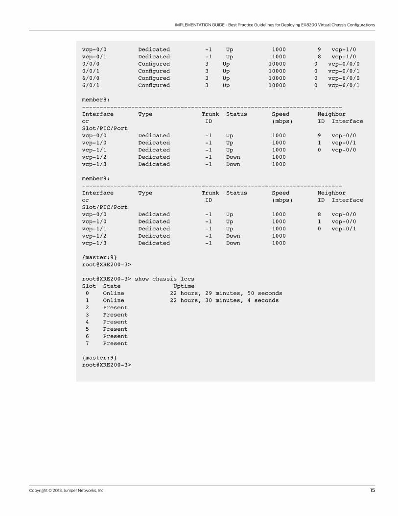
Virtual Chassis Show Commands
eX8200 Virtual Chassis status and topology information can be obtained from the following operational commands:
- show virtual-chassis
- show virtual-chassis vc-port
- show chassis lccs

14 Copyright © 2013, Juniper Networks, Inc.
IMPLEMENTATION GUIDE - Best Practice Guidelines for Deploying EX8200 Virtual Chassis Configurations
root@XRE200-3> show virtual-chassis
Preprovisioned Virtual ChassisVirtual Chassis ID: a72e.0aab.8526Virtual Chassis Mode: Enabled Mastership Neighbor List Member ID Status Serial No Model priority Role ID Interface0 (FPC 0-15) Prsnt BT0908500271 ex8208 0 Linecard 8 vcp-0/0 1 vcp-0/0/0 1 vcp-0/0/1 9 vcp-0/1 1 vcp-6/0/0 1 vcp-6/0/1 1 (FPC 16-31) Prsnt BT0908500274 ex8208 0 Linecard 9 vcp-0/0 0 vcp-0/0/0 0 vcp-0/0/1 8 vcp-0/1 0 vcp-6/0/0 0 vcp-6/0/1 8 (FPC 128-143) Prsnt 062010000001 ex-xre 129 Backup* 9 vcp-0/0 1 vcp-1/0 0 vcp-1/1 9 (FPC 144-159) Prsnt 062010000005 ex-xre 129 Master 8 vcp-0/0 1 vcp-1/0 0 vcp-1/1
{master:9}root@XRE200-3>
root@XRE200-3> show virtual-chassis vc-port member0:--------------------------------------------------------------------------Interface Type Trunk Status Speed Neighboror ID (mbps) ID InterfaceSlot/PIC/Portvcp-0/0 Dedicated -1 Up 1000 8 vcp-1/1vcp-0/1 Dedicated -1 Up 1000 9 vcp-1/10/0/0 Configured 3 Up 10000 1 vcp-0/0/00/0/1 Configured 3 Up 10000 1 vcp-0/0/16/0/0 Configured 3 Up 10000 1 vcp-6/0/06/0/1 Configured 3 Up 10000 1 vcp-6/0/1
member1:--------------------------------------------------------------------------Interface Type Trunk Status Speed Neighboror ID (mbps) ID InterfaceSlot/PIC/Port
Copyright © 2013, Juniper Networks, Inc. 15
IMPLEMENTATION GUIDE - Best Practice Guidelines for Deploying EX8200 Virtual Chassis Configurations
vcp-0/0 Dedicated -1 Up 1000 9 vcp-1/0vcp-0/1 Dedicated -1 Up 1000 8 vcp-1/00/0/0 Configured 3 Up 10000 0 vcp-0/0/00/0/1 Configured 3 Up 10000 0 vcp-0/0/16/0/0 Configured 3 Up 10000 0 vcp-6/0/06/0/1 Configured 3 Up 10000 0 vcp-6/0/1 member8:--------------------------------------------------------------------------Interface Type Trunk Status Speed Neighboror ID (mbps) ID InterfaceSlot/PIC/Portvcp-0/0 Dedicated -1 Up 1000 9 vcp-0/0vcp-1/0 Dedicated -1 Up 1000 1 vcp-0/1vcp-1/1 Dedicated -1 Up 1000 0 vcp-0/0vcp-1/2 Dedicated -1 Down 1000 vcp-1/3 Dedicated -1 Down 1000
member9:--------------------------------------------------------------------------Interface Type Trunk Status Speed Neighboror ID (mbps) ID InterfaceSlot/PIC/Portvcp-0/0 Dedicated -1 Up 1000 8 vcp-0/0vcp-1/0 Dedicated -1 Up 1000 1 vcp-0/0vcp-1/1 Dedicated -1 Up 1000 0 vcp-0/1vcp-1/2 Dedicated -1 Down 1000 vcp-1/3 Dedicated -1 Down 1000
{master:9}root@XRE200-3>
root@XRE200-3> show chassis lccs Slot State Uptime 0 Online 22 hours, 29 minutes, 50 seconds 1 Online 22 hours, 30 minutes, 4 seconds 2 Present 3 Present 4 Present 5 Present 6 Present 7 Present
{master:9}root@XRE200-3>

16 Copyright © 2013, Juniper Networks, Inc.
IMPLEMENTATION GUIDE - Best Practice Guidelines for Deploying EX8200 Virtual Chassis Configurations
Migrating EX8200 Standalone Switches to EX8200 Virtual Chassis Configurations
this section shows the sequence of steps required to migrate from a redundant standalone eX8200 configuration to a
Virtual Chassis configuration while in production to minimize the impact on active traffic flows.
In this test network, there are two traffic flows—a routed “l3” flow between tester ports 601/1 and 601/2 and a bridged/
switched “l2” flow between tester ports 601/3 and 601/4 connected to edge switches. the impact to the traffic flows
has been noted for each step.
the figure below shows the initial network configuration in the eX8200 standalone mode. the topology uses
redundant trunk group (rtG) laGs and VrrP to achieve loop-free forwarding paths.
switch eX8208-0 is the VrrP master and laGs between eX4200-0 and eX4200-1 are the rtG primary links.
Figure 5: Redundant pair of EX8200 running VRRP and RTg with all traffic flowing over master EX8200 switch
Migrating a pair of eX8200 standalone switches running VrrP to an eX8200 Virtual Chassis configuration involves the
following steps:
1. upgrade the switches to Junos os version 11.1
2. detach the first eX8200 switch from the access switches and the peer eX8200 switch
3. attach the first eX8200 switch to the pair of Xre200s and configure it in Virtual Chassis mode
4. revert the access switch links back to the first eX8200 switch, now in Virtual Chassis mode
5. attach the second eX8200 switch to the pair of Xre200s and configure it in Virtual Chassis mode
6. restore the access switch links back to the second eX8200 switch, now in Virtual Chassis mode
7. disable VrrP on the eX8200 switches, now in Virtual Chassis mode
EX8208-0
EX4200-0 EX4200-1
V110V200
xe-0/0/3xe-0/0/4xe-5/0/3xe-5/0/4
TestPort 601/310.1.200.63/24
TestPort 601/110.1.110.61/24
EX8208-1V30
V111V200
TestPort 601/410.1.200.64/24
TestPort 601/210.1.111.62/24
RTGAE to 8208-0 is primaryUplinks are non-revertive
OSPF Area 0Active on V30
Passive on V110-V111V200 – L2 VLAN
V110, V111 – VR IP .18202-0 is VRRP Master
.10 .11

Copyright © 2013, Juniper Networks, Inc. 17
IMPLEMENTATION GUIDE - Best Practice Guidelines for Deploying EX8200 Virtual Chassis Configurations
upgrade the Switches to latest Junos oS Version
see step 1 from the above section.
detach the first eX8208 from the access switches and the Peer eX8208
1. first increase the priority of eX8208-1 so that it preempts eX8208-0 and becomes the VrrP master. this will have
about one second impact on l3 traffic flows.
EX8208-0
EX4200-0 EX4200-1
V110V200
xe-0/0/3xe-0/0/4xe-5/0/3xe-5/0/4 ae2
ae0
ae0
xe-0/0/0 xe-1/0/0 xe-5/0/0
xe-4/0/0
ae1
EX8208-1
V111V200
V110, V111, V200, V30
set interfaces vlan unit 110 family inet address 10.1.110.11/24 vrrp-group 110 priority 250
set interfaces vlan unit 111 family inet address 10.1.111.11/24 vrrp-group 111 priority 250
2. on eX8208-0, disable edge facing aggregated ethernet (ae) interfaces and “commit” the changes. this will have
a sub-second impact on traffic flows. Next, disable the ae2 interface which interconnects the two chassis; this will
have zero impact on traffic flows.
set interface ae0 disable set interface ae1 disable commit set interface ae2 disable commit
3. on eX8208-1, disable the ae2 interface so that the VCP does not “come up” when configured on eX8208-0 in step 2.
set interfaces ae2 disable
Figure 6: all traffic flows through the backup EX8200 switch while master is being prepared to run EX8200 Virtual Chassis configuration
attach the first eX8208 to the Pair of Xre200s and Configure in Virtual Chassis Mode
1. from the console, load the factory default configuration on eX8208-0 and enable it to function in Virtual Chassis
mode:
root@8200-0>load factory-defaultroot@8200-0>set system root plainroot@8200-0>commit and-quit
root@switch>set chassis virtual-chassis

18 Copyright © 2013, Juniper Networks, Inc.
IMPLEMENTATION GUIDE - Best Practice Guidelines for Deploying EX8200 Virtual Chassis Configurations
2. Configure the master Xre200 (i.e., Xre200-8):
• the Xre200s must run the same version of software as the eX8208s.
• Create preprovisioned Virtual Chassis configuration on Xre200-8 for all members. for detailed steps, see “Create
Preprovisioned Virtual Chassis Configuration on Master Xre200” above.
• Interface me0 IP addressing from eX8208-0 can optionally be reused.
• Physically connect the Xre200s and verify that they are both “present.”
3. Configure the eX8200 switches via Xre200 configuration mode:
• Include the eX8208-1 configuration even though it is not yet physically connected.
• Note that ports on the second chassis start with fPC 16.
• there are now two laGs total in the Virtual Chassis. Because the rtG on the eX4200s is non-revertive, traffic
should not be received on these ports even though the links are “up.”
• VlaN: there is no need for an inter-chassis VlaN.
• IP: the IP addressing schemes do not change.
• VrrP: even though the eX8200 Virtual Chassis is one logical switch, this is required in the interim because
the hosts will continue to use the VrrP media access control (MaC) address, which is locally cached. to avoid
duplicate IP addresses between the eX8200 Virtual Chassis and eX8208-1.
• More details and a configuration example can be found here: www.juniper.net/techpubs/en_uS/junos/topics/
task/configuration/virtual-chassis-ex8200-cli.html.
• Physically connect the Xre200s and eX8208-0 routing engine management ports (which are now converted into
VCPs).
• from Xre200 operational mode, configure VCPs on eX8208-0 that interconnect the two chassis. Note that ports
on the eX8200-40Xs line card are not supported for VCP operation.
XRE200-9XRE200-8
EX8208-0Line Card 0
EX4200-0 EX4200-1
V110V200
xe-0/0/3
vcp-1/0
vcp-1/1
vcp-0/0 vcp-0/1
vcp-1/1
xe-0/0/4xe-5/0/3xe-5/0/4
VCP
ae1ae0
EX8208-1
V111V200
request virtual-chassis vc-port set fpc-slot 0 pic-slot 0 port 3 member 0 request virtual-chassis vc-port set fpc-slot 5 pic-slot 0 port 3 member 0
Figure 7: Single-member EX8200 Virtual Chassis is formed while all traffic flows through the backup EX8200

Copyright © 2013, Juniper Networks, Inc. 19
IMPLEMENTATION GUIDE - Best Practice Guidelines for Deploying EX8200 Virtual Chassis Configurations
Revert the access Switch links Back to the First EX8208, Now in Virtual Chassis Mode
1. Manually revert links on the eX4200s back to eX8208-0 via the ClI so that traffic flows through Virtual Chassis line
Card 0.
2. on the eX4200s, disable the ae1 interfaces connected to eX8208-1. use an application such as secureCrt,
Clusterssh, or Putty Connection Manager to execute a ClI command for multiple sessions simultaneously. this
will have a sub-second impact on the traffic flows.
set interface ae1 disable
commit
3. leave the ae1 ports disabled, as they will be reconfigured in the next step.
Figure 8: all traffic is migrated from backup EX8200 to the single-member EX8200 Virtual Chassis
XRE200-9XRE200-8
EX8208-0Line Card 0
EX4200-0 EX4200-1
V110V200
xe-0/0/3
vcp-1/0
vcp-1/1
vcp-0/0 vcp-0/1
vcp-1/1
xe-0/0/4xe-5/0/3xe-5/0/4
VCP
ae1 ae1ae0 ae1
EX8208-1
V111V200

20 Copyright © 2013, Juniper Networks, Inc.
IMPLEMENTATION GUIDE - Best Practice Guidelines for Deploying EX8200 Virtual Chassis Configurations
attach the Second EX8208 to the Pair of XRE200s and Configure It in Virtual Chassis Mode
Figure 9: all traffic flows through single-member EX8200 Virtual Chassis while backup EX8200 is configured to join EX8200 Virtual Chassis configuration
1. from the console, load the factory default setting on eX8208-1 and enable it to function in Virtual Chassis mode:
XRE200-9XRE200-8
EX8208-0Line Card 0
EX4200-0 EX4200-1
V110V200
xe-0/0/3
vcp-1/0
vcp-1/1 vcp-1/2
vcp-0/0 vcp-0/1
vcp-1/1 vcp-1/2
vcp-0/0 vcp-0/1
xe-0/0/4xe-5/0/3xe-5/0/4
VCP
ae1ae0
EX8208-1
V111V200
V110, V111
root@8200-1> load factory-default root@8200-1> set system root plain root@8200-1> commit and-quit root@switch> set chassis virtual-chassis
after eX8208-1 reboots, make the physical connections between the Xre200s and routing engine management ports
on eX8208-1.
from Xre200 operational mode, configure VCPs on eX8208-0 that interconnect the two chassis:
request virtual-chassis vc-port set fpc-slot 0 pic-slot 0 port 3 member 1 request virtual-chassis vc-port set fpc-slot 5 pic-slot 0 port 3 member 1

Copyright © 2013, Juniper Networks, Inc. 21
IMPLEMENTATION GUIDE - Best Practice Guidelines for Deploying EX8200 Virtual Chassis Configurations
Restore the access Switch links Back to the Second EX8208, Now in Virtual Chassis Mode
Figure 10: Traffic is load-balanced over both EX8200 switches migrated to two-member EX8200 Virtual Chassis
1. on each eX4200 switch, move the ports connected to eX8208-1 (ae1) into the laG that is connected to eX8208-0
(ae0).
2. remove rtG-related settings from the configuration:
XRE200-9XRE200-8
VirtualChassis
EX8208-0Line Card 0
EX8208-1Line Card 1
EX4200-0 EX4200-1
V110V200
xe-0/0/3
vcp-1/0
vcp-1/1 vcp-1/2
vcp-0/0 vcp-0/1
vcp-1/1 vcp-1/2
vcp-0/0 vcp-0/1
xe-0/0/4xe-5/0/3xe-5/0/4
VCP
ae0 ae0
V111V200
delete interfaces ae1
set interfaces xe-0/1/1 ether-options 802.3ad ae0 set interfaces xe-1/1/1 ether-options 802.3ad ae0 delete vlan v110 interface ae1.0 delete vlan v200 interface ae1.0 delete ethernet-switching-options redundant-trunk-group delete protocols rstp interface ae1.0
3. this re-enables the ports that were previously disabled in step 3. this will have zero to sub-second impact on all
traffic flows.

22 Copyright © 2013, Juniper Networks, Inc.
IMPLEMENTATION GUIDE - Best Practice Guidelines for Deploying EX8200 Virtual Chassis Configurations
the figure below depicts the logical network topology of the eX8200 Virtual Chassis configuration after the migration
is completed.
Figure 11: logical network topology of EX8200 Virtual Chassis configuration
Disable VRRP on the EX8200 Switches, Now in Virtual Chassis Mode
as mentioned earlier, one of the major advantages of the Virtual Chassis technology is to eliminate VrrP to provide
high availability and resiliency. so VrrP must be disabled on the eX8200s running in Virtual Chassis mode. however,
the existing VrrP virtual MaC address is cached in the access device’s arP tables, so they will continue to forward
traffic with the destination MaC of the VrrP virtual MaC address.
to refresh the arP tables of the end devices, VrrP must be deleted and its virtual IP addresses must be migrated to
the routed VlaN interfaces (rVIs). Next, to force the rVI interfaces to send out a gratuitous arP with the new MaC
address of the newly configured interface, the rVI interfaces must be disabled and re-enabled. as soon as the end
devices receive the G-arP messages, they will refresh their arP tables with the new MaC address of the rVI interface
and start forwarding traffic to the new destination MaC address. this may result in a traffic loss of 1 to 2 seconds.
step-by-step procedure to disable VrrP:
a) delete VrrP on rVI:
edit interfaces vlan unit 110 family inet delete address 10.1.110.11/24 vrrp-group 110 virtual-address 10.1.110.1
b) Configure VrrP virtual IP (VIP) address on the rVI:
set address 10.1.110.1/24 exit
c) disable the rVI and commit:
set interfaces vlan unit 110 disable
d) enable the rVI and commit:
delete interfaces vlan unit 110 disable
EX8208
EX4200-0 EX4200-1
V110V200
ae0
V111V200
ae0
ae1
TestPort 601/310.1.200.63/24
TestPort 601/110.1.110.61/24
TestPort 601/410.1.200.64/24
TestPort 601/210.1.111.62/24
.1

Copyright © 2013, Juniper Networks, Inc. 23
IMPLEMENTATION GUIDE - Best Practice Guidelines for Deploying EX8200 Virtual Chassis Configurations
EX8200 Virtual Chassis high availability Best Practices
eX8200 Virtual Chassis configurations are highly resilient, with no single point of failure. the eX8200 Virtual
Chassis architecture ensures that no single failure of an element—a chassis, a line card, a routing engine, or an
interconnection—can render the entire Virtual Chassis inoperable. this is achieved by the combination of hardware and
software architectures discussed in the early part of this document.
to achieve a highly resilient, fully redundant eX8200 Virtual Chassis configuration with no single point of failure in
hardware, control plane, and data plane, the following features must be configured:
1. fully meshed redundant eX8200 Virtual Chassis configuration with four-member, multi-fPC, intra-Virtual Chassis
interconnections as depicted in figure 12 below.
Figure 12: Two-member EX8200 Virtual Chassis with dual-homed access devices.
2. Gres on both Xre200s:
Intra-XRE connection for HA (1GbE)
xe-2/0/0xe-2/0/1xe-4/0/4xe-4/0/5
xe-7/0/0xe-4/0/0
ae0
xe-23/0/0xe-20/0/0
ae1
Active XRE200
EX8216-1Line Card 1
EX8216-0Line Card 0
Standby XRE200
EX4500-0 EX4500-1
Active XRE to internal Routing Engine connection (1GbE)Standby XRE to internal Routing Engine connection (1GbE)10GbE LAG intra-Virtual Chassis connection10GbE Links
set chassis redundancy graceful-switchover
3. Nsr for routing protocols:
set routing-options nonstop-routing
4. Multi-lCC laGs for access switches. In figure 12, eX4500-0 and eX4500-1 are connected to the eX8200 Virtual
Chassis configuration via multi-lCC laGs:
set interfaces xe-4/0/0 ether-options 802.3ad ae0 set interfaces xe-20/0/0 ether-options 802.3ad ae0 set interfaces xe-7/0/0 ether-options 802.3ad ae1 set interfaces xe-23/0/0 ether-options 802.3ad ae1
5. laCP on the laGs in slow periodic mode:
set interfaces ae0 aggregated-ether-options lacp active set interfaces ae0 aggregated-ether-options lacp periodic slow
6. xstP and VrrP are completely disabled.
7. the above mentioned steps allow users to achieve a sub-second traffic loss of around 650 to 850 milliseconds
during an Nssu operation.

24 Copyright © 2013, Juniper Networks, Inc.
IMPLEMENTATION GUIDE - Best Practice Guidelines for Deploying EX8200 Virtual Chassis Configurations
EX8200 Virtual Chassis Failover Convergence Times
this section describes the convergence times in the event of different types of failures for the topology shown in figure 13.
the configuration highlights of the eX8200 Virtual Chassis systems are as described in the “Best Practices” section above.
Figure 13: a pair of two-member EX8200 Virtual Chassis configurations with dual-homed access devices interconnected via MPlS
Table 4: high availability and Resiliency Convergence Test Results for Figure 13
EVENT RESulT
disconnect/restore single laG member from top-of-rack Virtual
Chassis #1 switch to eX8200 Virtual Chassis #1
disconnect: sub-second packet loss
restore: zero packet loss
disconnect/restore laG members so that all traffic is passing
through VCP ports on eX8200 Virtual Chassis1
disconnect: sub-second packet loss
restore: zero packet loss
Pull out line card on eX8200 Virtual Chassis1 on which one of
the laG members resides
Zero packet loss
Pull out re0 from eX8216-0 (Member0 of eX8200 Virtual
Chassis #1)
Zero packet loss
restore re0 from eX8216-0 Zero packet loss
Power off/on Xre200-1 (master) of eX8200 Virtual Chassis #1
laCP (slow interval) configured on all link bundles
Power off: sub-second packet loss
Power on: zero packet loss
Power on/off Xre200-0 (backup) of eX8200 Virtual Chassis #1
No laCP configured on all link bundles (static)
Zero packet loss
Pull out/restore sCB 0 of eX8216-0 (member0) sub-second packet loss
Zero packet loss
Power off/on member0
Power on eX8216-1
sub-second packet loss
sub-millisecond packet loss
Manual switchover of master routing engine (Xre200-0 >
Xre200-1, request chassis routing engine master switch)
sub-second packet loss
Nonstop upgrade eX8200 Virtual Chassis sub-second packet loss
VCP-LAG
LAGTest Port #2
Top of RackVirtual Chassis #3
Top of RackVirtual Chassis #4
Top of RackVirtual Chassis #1
Top of RackVirtual Chassis #2
EX8200Virtual Chassis #1
Dual Homed Servers Dual Homed Servers
EX8208-1
L3 LAG
LAG
LAG
VCP
LAG
EX8200Virtual Chassis #2
EX8208-2MPLS
L3 LAG
LAG
Test Port #3
Test Port #1
Test Port #4

Copyright © 2013, Juniper Networks, Inc. 25
IMPLEMENTATION GUIDE - Best Practice Guidelines for Deploying EX8200 Virtual Chassis Configurations
EX8200 Virtual Chassis over long Distances Configuration Steps
Physical Connections of XRE200s and Intermediate Switches
Figure 14: Two XRE200s connected to each other via EX2200 over long distance
1. assume that ports ge-0/0/0 and ge-0/0/1 on switch a in figure 5 are connected to ports vcp-0/0 and vcp-0/1
on the active Xre200 and are the inter-Xre and Xre-lCC1 VCPs, respectively. also, port ge-0/0/2 on switch a is
connected to port vcp-1/0 on lCC0.
2. assume that ports ge-0/0/0 and ge-0/0/1 on switch B are connected to ports vcp-0/0 and vcp-0/1 on the standby
Xre200. also, port ge-0/0/2 on switch B is connected to port vcp-1/0 on lCC1.
3. assume that fiber ports ge-0/1/0, ge-0/1/1, and ge-0/1/2 on switch a and switch B are interconnected.
4. therefore, on switches a and B, the copper ports ge-0/0/0 through ge-0/0/2 pair up with their respective fiber
ports ge-0/1/0 through ge-0/1/2 for unidirectional failure detection protocol (ufd) configuration.
Configuration on Intermediate Switches
switch a Configuration and Verification
1. Configure ports ge-0/0/0 and ge-0/1/0 in the same VlaN, say VlaN 10:
XRE200-8
To LCC0 Master To LCC0 Backup To LCC1 Master To LCC1 Backup
UFD on Switch A:ge-0/0/0 tracks ge-0/1/0ge-0/0/1 tracks ge-0/1/1ge-0/0/2 tracks ge-0/1/2
UFD on Switch B:ge-0/0/0 tracks ge-0/1/0ge-0/0/1 tracks ge-0/1/1ge-0/0/2 tracks ge-0/1/2
XRE200-9Switch A -EX2200vcp-0/0 ge-0/0/0 vcp-0/0ge-0/0/0
vcp-0/1ge-0/0/1
ge-0/1/0 ge-0/1/0
ge-0/1/3 ge-0/1/3
ge-0/1/2 ge-0/1/2
vcp-0/1vcp-1/0 ge-0/0/2 vcp-1/0ge-0/0/2
ge-0/0/1
Switch B -EX2200
root@SwitchA> configure root@SwitchA# set vlans vlan10 vlan-id 10root@SwitchA# set interfaces ge-0/0/0 unit 0 family ethernet-switchingroot@SwitchA# set interfaces ge-0/1/0 unit 0 family ethernet-switching root@SwitchA# set vlans vlan10 interface ge-0/0/0root@SwitchA# set vlans vlan10 interface ge-0/1/0
2. Configure ports ge-0/0/1 and ports ge-0/1/1 in the same VlaN, say VlaN 20:
root@SwitchA# set vlans vlan20 vlan-id 20root@SwitchA# set interfaces ge-0/0/1 unit 0 family ethernet-switchingroot@SwitchA# set interfaces ge-0/1/1 unit 0 family ethernet-switching root@SwitchA# set vlans vlan20 interface ge-0/0/1root@SwitchA# set vlans vlan20 interface ge-0/1/1
3. Configure ports ge-0/0/2 and ports ge-0/1/2 in the same VlaN, say VlaN 30:
root@SwitchA# set vlans vlan30 vlan-id 30root@SwitchA# set interfaces ge-0/0/2 unit 0 family ethernet-switchingroot@SwitchA# set interfaces ge-0/1/2 unit 0 family ethernet-switchingroot@SwitchA# set vlans vlan30 interface ge-0/0/2root@SwitchA# set vlans vlan30 interface ge-0/1/2

26 Copyright © 2013, Juniper Networks, Inc.
IMPLEMENTATION GUIDE - Best Practice Guidelines for Deploying EX8200 Virtual Chassis Configurations
4. Configure three ufd groups so that any failures of the fiber links will trigger the ufd protocol to disable the
corresponding copper Virtual Chassis link:
root@SwitchA# edit protocols uplink-failure-detection root@SwitchA# set group Inter-XRE link-to-monitor ge-0/1/0root@SwitchA# set group Inter-XRE link-to-disable ge-0/0/0root@SwitchA# set group XRE-Master-RE link-to-monitor ge-0/1/1root@SwitchA# set group XRE-Master-RE link-to-disable ge-0/0/1root@SwitchA# set group XRE-Backup-RE link-to-monitor ge-0/1/2root@SwitchA# set group XRE-Backup-RE link-to-disable ge-0/0/2root@SwitchA# commit
5. Verify the ufd configuration:
root@SwitchA> show uplink-failure-detection Group : Inter-XRE Uplink : ge-0/1/0 Downlink : ge-0/0/0 Failure Action : Inactive
Group : XRE-Master-RE Uplink : ge-0/1/1 Downlink : ge-0/0/1 Failure Action : Inactive
Group : XRE-Backup-RE Uplink : ge-0/1/2 Downlink : ge-0/0/2
Failure Action : Inactive
6. Configure 802.3ah on all of the fiber ports:
root@SwitchA# set protocols oam ethernet link-fault-management interface ge-0/1/0root@SwitchA# set protocols oam ethernet link-fault-management interface ge-0/1/1root@SwitchA# set protocols oam ethernet link-fault-management interface ge-0/1/2root@SwitchA# commit
7. Configure Jumbo frames on all interfaces.
root@SwitchA# set interface ge-0/0/0 mtu 9216root@SwitchA# set interface ge-0/0/1 mtu 9216root@SwitchA# set interface ge-0/0/2 mtu 9216root@SwitchA# set interface ge-0/1/0 mtu 9216root@SwitchA# set interface ge-0/1/1 mtu 9216root@SwitchA# set interface ge-0/1/2 mtu 9216root@SwitchA# commit
switch B Configuration and Verification
1. Configure ports ge-0/0/0 and ge-0/1/0 in the same VlaN, say VlaN 10:
root@SwitchB> configure root@SwitchB# set vlans vlan10 vlan-id 10root@SwitchB# set interfaces ge-0/0/0 unit 0 family ethernet-switchingroot@SwitchB# set interfaces ge-0/1/0 unit 0 family ethernet-switching root@SwitchB# set vlans vlan10 interface ge-0/0/0
root@SwitchB# set vlans vlan10 interface ge-0/1/0

Copyright © 2013, Juniper Networks, Inc. 27
IMPLEMENTATION GUIDE - Best Practice Guidelines for Deploying EX8200 Virtual Chassis Configurations
2. Configure ports ge-0/0/1 and ports ge-0/1/1 in the same VlaN, say VlaN 20:
root@SwitchB# set vlans vlan20 vlan-id 20root@SwitchB# set interfaces ge-0/0/1 unit 0 family ethernet-switchingroot@SwitchB# set interfaces ge-0/1/1 unit 0 family ethernet-switching root@SwitchB# set vlans vlan20 interface ge-0/0/1root@SwitchB# set vlans vlan20 interface ge-0/1/1
3. Configure ports ge-0/0/2 and ports ge-0/1/2 in the same VlaN, say VlaN 30:
root@SwitchB# set vlans vlan30 vlan-id 30root@SwitchB# set interfaces ge-0/0/2 unit 0 family ethernet-switchingroot@SwitchB# set interfaces ge-0/1/2 unit 0 family ethernet-switching root@SwitchB# set vlans vlan30 interface ge-0/0/2root@SwitchB# set vlans vlan30 interface ge-0/1/2
4. Configure three ufd groups so that any failures of the fiber links will trigger the ufd protocol to disable the
corresponding copper Virtual Chassis link:
root@SwitchB# edit protocols uplink-failure-detection [edit protocols uplink-failure-detection]root@SwitchB# set group Inter-XRE link-to-monitor ge-0/1/0root@SwitchB# set group Inter-XRE link-to-disable ge-0/0/0root@SwitchB# set group XRE-Master-RE link-to-monitor ge-0/1/1root@SwitchB# set group XRE-Master-RE link-to-disable ge-0/0/1root@SwitchB# set group XRE-Backup-RE link-to-monitor ge-0/1/2root@SwitchB# set group XRE-Backup-RE link-to-disable ge-0/0/2root@SwitchB# commit
5. Verify the ufd configuration:
root@SwitchB> show uplink-failure-detection
Group : Inter-XRE Uplink : ge-0/1/0 Downlink : ge-0/0/0 Failure Action : Inactive
Group : XRE-Master-RE Uplink : ge-0/1/1 Downlink : ge-0/0/1 Failure Action : Inactive
Group : XRE-Backup-RE Uplink : ge-0/1/2 Downlink : ge-0/0/2 Failure Action : Inactive
Note that the above configurations on switches a and B ensure that fiber breaks cause the copper ports to be disabled
and not vice versa. therefore, a copper port failure or an Xre200 reboot may result in up to one minute of traffic loss.
6. Configure 802.3ah on all of the fiber ports:
root@SwitchB# set protocols oam ethernet link-fault-management interface ge-0/1/0root@SwitchB# set protocols oam ethernet link-fault-management interface ge-0/1/1root@SwitchB# set protocols oam ethernet link-fault-management interface ge-0/1/2root@SwitchB# commit

28 Copyright © 2013, Juniper Networks, Inc.
IMPLEMENTATION GUIDE - Best Practice Guidelines for Deploying EX8200 Virtual Chassis Configurations
7. Configure Jumbo frames on all interfaces.
XRE200 Configuration
1. enable Gres and failover on loss of keepalive on both Xre200s:
root@SwitchB# set interface ge-0/0/0 mtu 9216root@SwitchB# set interface ge-0/0/1 mtu 9216root@SwitchB# set interface ge-0/0/2 mtu 9216root@SwitchB# set interface ge-0/1/0 mtu 9216root@SwitchB# set interface ge-0/1/1 mtu 9216root@SwitchB# set interface ge-0/1/2 mtu 9216root@SwitchB# commit
root@xre200-8# show chassis redundancyfailover on-loss-of-keepalives;graceful-switchover;
root@xre200-9# show chassis redundancyfailover on-loss-of-keepalives;graceful-switchover;
Conclusion
eX8200 switches with Virtual Chassis technology address the fundamental requirements of a core or collapsed core/
aggregation switch, delivering a solution for implementing a network fabric in campus and data center environments.
eX8200 Virtual Chassis configurations support multipathing and eliminate the inefficiencies associated with spanning
tree Protocol (stP), providing a highly resilient system, and simplifying management and control plane operations
at scale. Virtual Chassis technology on the eX8200 modular platforms also reduces the bandwidth inefficiencies
associated with stP to accelerate network convergence and simplify network architecture.
Virtual Chassis technology on the high capacity eX8200 line of ethernet switches delivers a cost-effective solution
that simultaneously achieves the following objectives:
• extending the core switching capacity beyond the eX8216 switch’s limit of 2.5 tbps
• Protecting the network against any single point of failure
• fully utilizing redundant paths of the network by eliminating the need for spanning tree Protocol and VrrP
Implicitly, the deployment of a Virtual Chassis configuration reduces the number of devices that need to be managed,
with all of the costs for power and maintenance that come with them. the simple steps and recommendations
outlined in this guide will help you take full advantage of these benefits.

Copyright © 2013, Juniper Networks, Inc. 29
IMPLEMENTATION GUIDE - Best Practice Guidelines for Deploying EX8200 Virtual Chassis Configurations
8010081-003-eN Jan 2013
Copyright 2013 Juniper Networks, Inc. all rights reserved. Juniper Networks, the Juniper Networks logo, Junos, Netscreen, and screenos are registered trademarks of Juniper Networks, Inc. in the united states and other countries. all other trademarks, service marks, registered marks, or registered service marks are the property of their respective owners. Juniper Networks assumes no responsibility for any inaccuracies in this document. Juniper Networks reserves the right to change, modify, transfer, or otherwise revise this publication without notice.
aPaC and EMEa headquarters
Juniper Networks International B.V.
Boeing avenue 240
1119 PZ schiphol-rijk
amsterdam, the Netherlands
Phone: 31.0.207.125.700
fax: 31.0.207.125.701
Corporate and Sales headquarters
Juniper Networks, Inc.
1194 North Mathilda avenue
sunnyvale, Ca 94089 usa
Phone: 888.JuNIPer (888.586.4737)
or 408.745.2000
fax: 408.745.2100
www.juniper.net
to purchase Juniper Networks solutions,
please contact your Juniper Networks
representative at 1-866-298-6428 or
authorized reseller.
Printed on recycled paper
about Juniper Networks
Juniper Networks is in the business of network innovation. from devices to data centers, from consumers to cloud
providers, Juniper Networks delivers the software, silicon and systems that transform the experience and economics
of networking. the company serves customers and partners worldwide. additional information can be found at
www.juniper.net.


