
Brief History of
e+e- Circular Colliders
Emphasizing Future Applications
John Seeman,
SLAC
IAS Workshop HKIST
January 2015

2
List of e+e- Colliders

3
List of e+e- Colliders (cont)
SuperKEKB KEK, Japan 7x 4 GeV Spring 2015!
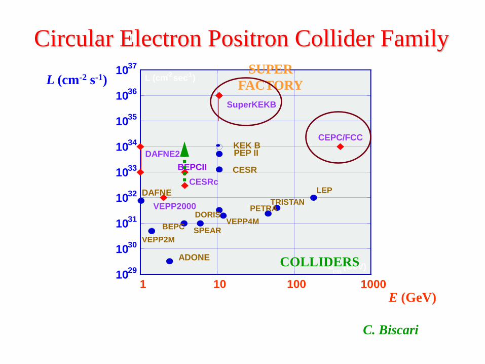
10 29
10 30
10 31
10 32
10 33
10 34
10 35
10 36
10 37
1 10 100 1000
CEPC/FCC
ADONE
VEPP2000
SuperKEKB
KEK B PEP II
CESR
DAFNE
DAFNE2
BEPCII
CESRc
E cm
(GeV)
L (cm -2
sec -1
)
VEPP2M
LEP
TRISTAN PETRA
VEPP4M DORIS
SPEAR BEPC
COLLIDERS
SUPER
FACTORY
Circular Electron Positron Collider Family
C. Biscari
L (cm-2 s-1)
E (GeV)

5
Luminosity Scaling with Beam Energy (M. Zanetti)

6
Earliest Colliders (Early 1960’s)
ADA e+e- Frascati
(Touschek scattering discovered)
CBX e-e- Stanford
(Stored 1 Amp/per beam,
beam-beam tune shift observed))

7
Low energy colliders (1970s)
ADONE Frascati
(Longitudinal feedback,
adjustable damping partitions)
ACO Orsay
(Ring based FEL studies)
8
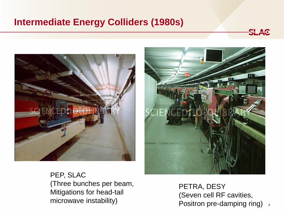
Intermediate Energy Colliders (1980s)
PEP, SLAC
(Three bunches per beam,
Mitigations for head-tail
microwave instability)
PETRA, DESY
(Seven cell RF cavities,
Positron pre-damping ring)

9
Phi-Tau-Charm Colliders
SPEAR
(Flexible
Lattice)
DAFNE
(Crab waist)
VEPP-2000
(Round beams)
BEPC-I&II
(SC RF)
10
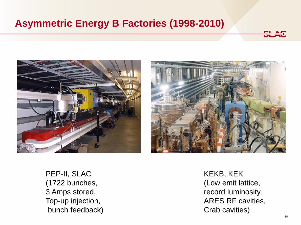
Asymmetric Energy B Factories (1998-2010)
PEP-II, SLAC
(1722 bunches,
3 Amps stored,
Top-up injection,
bunch feedback)
KEKB, KEK
(Low emit lattice,
record luminosity,
ARES RF cavities,
Crab cavities)

11
Z Colliders
LEP, CERN
(high beam energy 104 GeV
Pretzel orbit, concrete dipoles)
SLC, SLAC
(First linear collider,
BNS damping, e- polarization at IP)

SuperKEKB nearing completion
12
(nano-beam emittances, mm level IP vert betas)
13
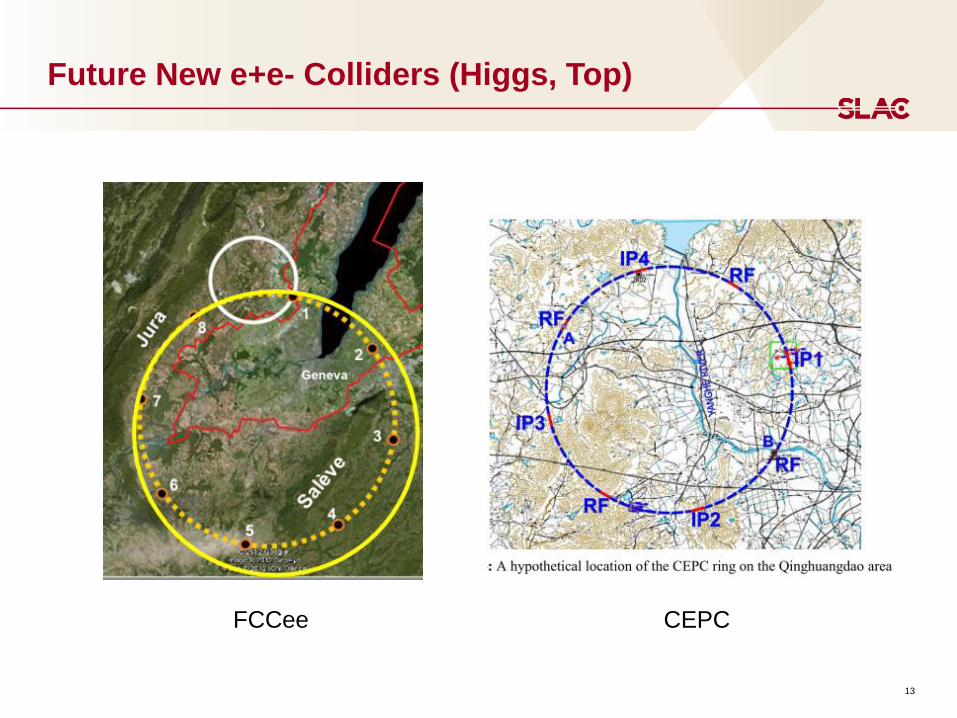
Future New e+e- Colliders (Higgs, Top)
CEPC FCCee
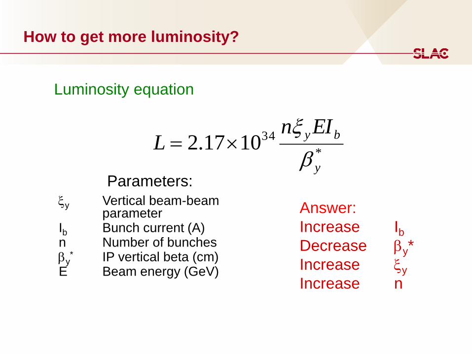
How to get more luminosity?
xy Vertical beam-beam parameter Ib Bunch current (A) n Number of bunches by
* IP vertical beta (cm) E Beam energy (GeV)
*
341017.2y
byEInL
b
x
Luminosity equation
Answer:
Increase Ib
Decrease by*
Increase xy
Increase n
Parameters:

15
General Observations e+e- Colliders (1)
Lattices:
x-y chromatic coupling in the IR is important: skew
sextupoles.
Sextupole and skew quadrupole coupling corrections in IR
More studies of IR error tolerances needed.
Instabilities:
More work on e-cloud to allow more bunches.
Beam-Beam Calculations:
Need mores studies of non-linear beam dynamics.
Parasitic crossing studies
Beam lifetimes:
Short beam lifetimes expected in the next collider (~10
minutes) with continuous top-off needed.

16
General Observations Lepton e+e- Colliders (2)
Tunes:
For best collisions: nx = ~0.505, ny = 0.512-0.518,
Crab cavities:
Crab cavities tilt bunches as expected at IP.
Expected luminosity gains not, so far, fully achieved.
Must include dynamic beta effects with respect to ring apertures.
Crab cavity trip rates need some additional study.
Large Piwinski Angle:
Works in a collider.
Allows nx >0.505
Crab waist:
Crab waist can potentially improve the luminosity.
Effects of crab sextupoles on dynamic aperture needs work.
Round beams:
Initial beam tests look promising.
Additional tolerance studies are needed.
17
Interaction Point Design
Key issues: 1 mm to 300 micron scale by*, large betas in IR quadrupoles,
quadrupoles inside the detector, collision feedback, vacuum chamber design,
magnet tolerances, alignment and jitter tolerances, crab cavities, crab waist
Test accelerators/facilities: SuperKEKB, CESR-TA, PETRA-3, vibration stabilization
facility
Technologies:
100+ Hz IP dither feedback on luminosity
Superconducting magnets
Permanent magnets
Power supply stability
Vibration control
Non-linear optics

18
SuperKEKB Interaction Region
Superconducting quadrupoles
In the interaction region
Two beam passages
Need to shield stray fields.
Magnet inner radius=22 mm,
Outer radius=27.86 mm
Magnet current=1622 A
Field gradient=80.63 T/m
19
Machine Detector Interface
Key issue: Synchrotron radiation backgrounds, lost particle backgrounds, SR
heating of vacuum chambers, radiation damage/lifetime of detectors, sensor
occupancy, luminosity measurement.
Test accelerators/facilities: SuperKEKB, LHC, lab tests of high power vacuum
chambers, lab tests of detector lifetime
Technologies:
IP vacuum pumping
Advanced masking
Rapid luminosity feedback
Detector design
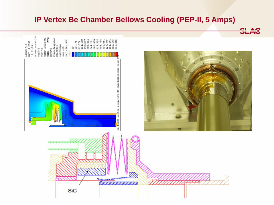
IP Vertex Be Chamber Bellows Cooling (PEP-II, 5 Amps)

21
SuperKEKB Fast Dither Feedback (Wienands, Funakoshi)
22
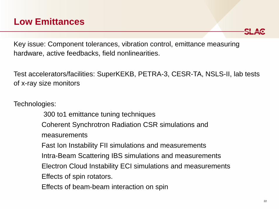
Low Emittances
Key issue: Component tolerances, vibration control, emittance measuring
hardware, active feedbacks, field nonlinearities.
Test accelerators/facilities: SuperKEKB, PETRA-3, CESR-TA, NSLS-II, lab tests
of x-ray size monitors
Technologies:
300 to1 emittance tuning techniques
Coherent Synchrotron Radiation CSR simulations and
measurements
Fast Ion Instability FII simulations and measurements
Intra-Beam Scattering IBS simulations and measurements
Electron Cloud Instability ECI simulations and measurements
Effects of spin rotators.
Effects of beam-beam interaction on spin

Comparison of Emittances of Colliders
Existing colliders
Future colliders
Courtesy of F. Zimmermann, H. Burkhardt and Q. Qin
LEP3
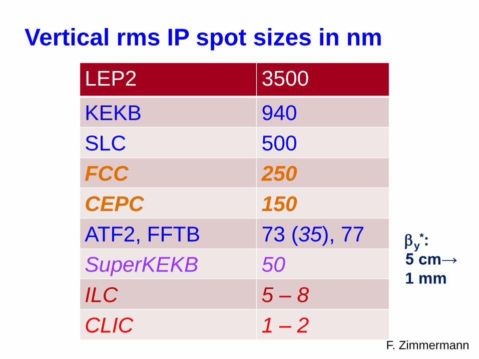
Vertical rms IP spot sizes in nm
LEP2 3500
KEKB 940
SLC 500
FCC 250
CEPC 150
ATF2, FFTB 73 (35), 77
SuperKEKB 50
ILC 5 – 8
CLIC 1 – 2
by*:
5 cm→
1 mm
F. Zimmermann

25
Lattice and Dynamic Aperture Calculations
Chao, Cai)
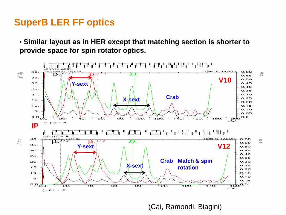
• Similar layout as in HER except that matching section is shorter to
provide space for spin rotator optics.
SuperB LER FF optics
IP
V10
Y-sext
X-sext
Crab
V12
Match & spin
rotation
Crab
X-sext
Y-sext
(Cai, Ramondi, Biagini)
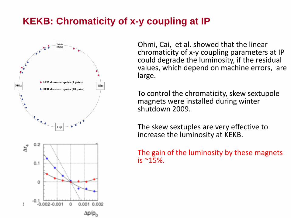
Ohmi, Cai, et al. showed that the linear chromaticity of x-y coupling parameters at IP could degrade the luminosity, if the residual values, which depend on machine errors, are large. To control the chromaticity, skew sextupole magnets were installed during winter shutdown 2009. The skew sextuples are very effective to increase the luminosity at KEKB. The gain of the luminosity by these magnets is ~15%.
Tsukuba
(Belle)
Nikko Oho
Fuji
LER skew-sextupoles (4 pairs)
HER skew-sextupoles (10 pairs)
KEKB: Chromaticity of x-y coupling at IP
28
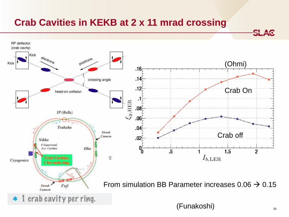
Crab Cavities in KEKB at 2 x 11 mrad crossing
Crab On
Crab off
From simulation BB Parameter increases 0.06 0.15
(Ohmi)
(Funakoshi)
x
y2
x
y2
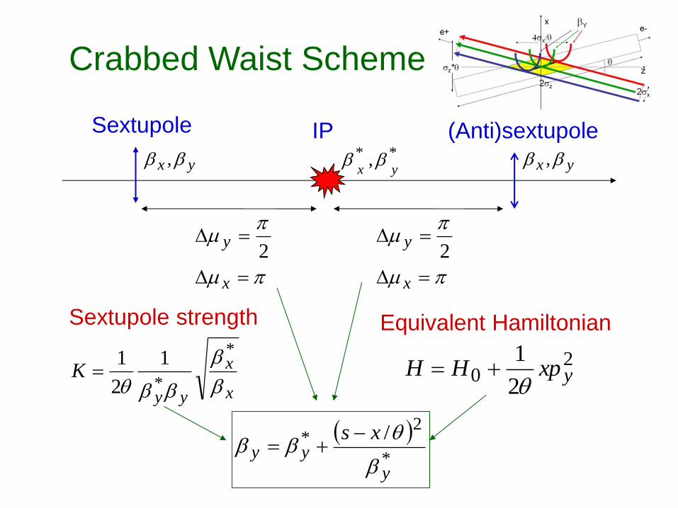
Crabbed Waist Scheme
x
x
yy
Kb
b
bb
*
*
1
2
1
Sextupole (Anti)sextupole
20
2
1yxpHH
Sextupole strength Equivalent Hamiltonian
IP
yx bb , yx bb ,** ,yx
bb
*
2* /
y
yyxs
b
bb

DAFNE Crab Waist:
1.Small emittance ex
2.Large Piwinski angle F >> 1
3.Larger crossing angle
4.Longer bunch length sz
5.Strong nonlinear elements (sextupoles)
(Zobov)

How the crabbed waist works Crab sextupoles OFF: Waist line is orthogonal to the axis of the beam
Crab sextupoles ON: Waist moves parallel to the axis of other beam:
maximum particle density in the overlap between bunches
Plots by E. Paoloni
All particles in both beams collide in the minimum by region,
with a net luminosity gain

32
Frascati: DAFNE: Large Piwinski angle and crab waist
DAFNE will run for luminosity for at least the next two to three years.

Dynamic aperture studies with crab waist (SuperB studies)
Piminov, Chancé
omparison (Piminov) codes
nd few discrepa-cies (MADX
more realistic model)
corrected, now in agreement
Found that, as expected, crab-waist sextupoles reduce dynamic aperturebetween MADX (Chancé) and Acceleraticum
K. Ohmi
34
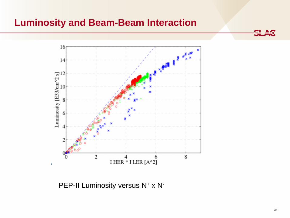
Luminosity and Beam-Beam Interaction
PEP-II Luminosity versus N+ x N-
35
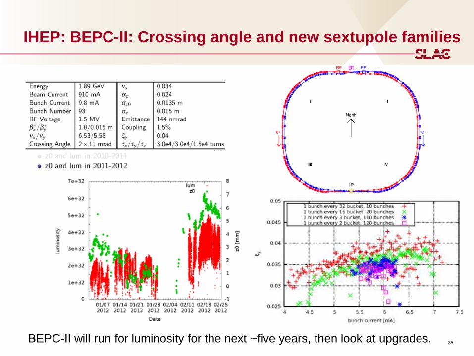
IHEP: BEPC-II: Crossing angle and new sextupole families
BEPC-II will run for luminosity for the next ~five years, then look at upgrades.

Simulations: Beam-beam tune plane scan
CDR, xy = 0.17 CDR2, xy = 0.097
L (red) = 1. ∙1036
0.5 0.52 0.54 0.56 0.58 0.6 0.62 0.64
0.5
0.52
0.54
0.56
0.58
0.6
0.62
0.64
0.5 0.52 0.54 0.56 0.58 0.6 0.62 0.64
0.5
0.52
0.54
0.56
0.58
0.6
0.62
0.64
Shatilov
Crab waist gives better performance.
Synchro-betatron resonances are still present.
37
High Current Effects
Key issues: Beam stability, high power RF, high power vacuum components, AC
wall efficiency, injector capabilities, I> 1 A.
Test accelerators/facilities: SuperKEKB, CESR-TA
Technologies:
Better bunch feedbacks
Electron cloud instability control
Intra-beam scattering mitigations
Fast ion instability mitigations
More efficient klystrons
High power cavities
Longitudinal beam feedback

New transverse kicker electrodes (SLAC, KEK)
Page 39
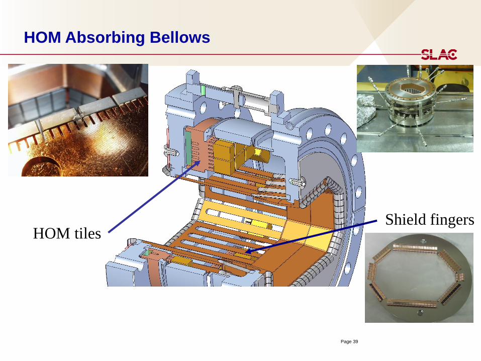
HOM Absorbing Bellows
HOM tiles Shield fingers

Intra Beam Scattering
Three methods used, all in good agreement:
• Allows for emittance growth rates estimate and for emittance time evolution estimate
• 6D MonteCarlo more accurate, all of above, will include non-gaussian tails
ex,z vs bunch current
Boscolo, Chao, Demma
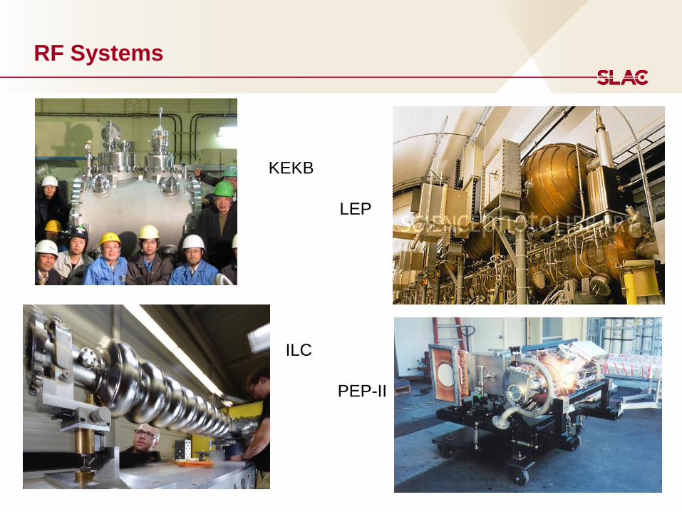
RF Systems
KEKB
LEP
ILC
PEP-II

High Beam Power Recipe
Higher currents and shorter bunches lead directly to much higher wake-field effects
• HOM power and CSR
Vacuum chamber impedances must be minimized
• Causes bunch lengthening
• Hard to do a lot better than present B-factories
All components must be water-cooled
• Again, difficult to do much better than present B-factories
SR power levels increase with higher beam currents causing higher total beam losses
• More RF power needed to restore the lost beam energy – more plug power

RF System Overall for FCC/CEPC
An RF system based on about 700 MHz SC cavity technology seems
reasonable.
• ongoing R&D at BNL, CERN, ESS for 704 MHz cavities and components
• RF wall-plug to beam efficiency around 55 % (w/o cryogenics)
Open questions and R&D necessary
• fundamental power couplers: R&D ongoing
• HOM damping scheme: study needed
• low level RF & feedback requirements: study needed
• construction and testing cost are an issue.
Butterworth, Jensen, etc
44
Longitudinally Polarized e- Beam at the Interaction Point
Key issue: Injected polarization, beam lifetime, polarization lifetime, spin
rotators, polarization measurements, effect on IP optics, beam-beam effect on
polarization.
Technologies:
Siberian snakes
Solenoidal rotators
Beam-beam depolarization diagnostics
Spin manipulation in the Damping Ring and Linac.
e- polarized source

Longitudinal Polarization at the Interaction Point with
Vertical in the ARCs needing Spin Rotation (SuperB)
IP HER
HER LER
LER
S.r. solenoids
(90° spin)
S.r. dipoles
(270° spin)
90° spin rotation about x axis
• 90° about z followed by 90° about y
“flat” geometry => no vertical emittance growth
Solenoid scales with energy => LER more economical
Solenoids are split & decoupling optics added.
Wienands)
CEPC-FCC:
Lifetime limit due to beam-beam, luminosity (Bhabha),
beamstrahlung, Touschek, and vacuum.
tbeam~16 minutes
Beam Lifetime
SuperKEKB: t~6-10 minutes!
Required: Full energy and Top-Up Injection.

47
Top-Up or Continuous Injection In PEP-II
U. Wienands
48
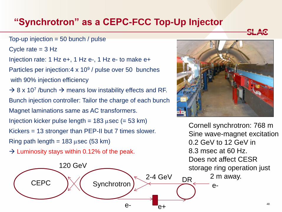
“Synchrotron” as a CEPC-FCC Top-Up Injector
Top-up injection = 50 bunch / pulse
Cycle rate = 3 Hz
Injection rate: 1 Hz e+, 1 Hz e-, 1 Hz e- to make e+
Particles per injection:4 x 10⁹ / pulse over 50 bunches
with 90% injection efficiency
8 x 10⁷ /bunch means low instability effects and RF.
Bunch injection controller: Tailor the charge of each bunch
Magnet laminations same as AC transformers.
Injection kicker pulse length = 183 sec (= 53 km)
Kickers = 13 stronger than PEP-II but 7 times slower.
Ring path length = 183 sec (53 km)
Luminosity stays within 0.12% of the peak.
Cornell synchrotron: 768 m
Sine wave-magnet excitation
0.2 GeV to 12 GeV in
8.3 msec at 60 Hz.
Does not affect CESR
storage ring operation just
2 m away. CEPC Synchrotron
e+
e- DR
e-
2-4 GeV
120 GeV

49
Conclusions
e+e- colliders have had a spectacular history.
Very mature knowledge base on which to design the next accelerator.
Many new accelerator physics and technology discoveries and solutions
were found over the years. We need to continue to pursue new R&D and
required technologies to make the next round of colliders viable.
Any new large accelerator should have a bold but achievable energy-
physics reach.
Every geographical region should design to world high energy physics
goals while making use of local advantages.


