Download - C04-Wireless Telecommunication Systems

4.1Prof. Dr.-Ing. Jochen H. Schiller www.jochenschiller.de MC - 2009
Mobile CommunicationsChapter 4: Wireless Telecommunication Systems
• Market
• GSM
• DECT
• TETRA
• UMTS/IMT-2000
4.2Prof. Dr.-Ing. Jochen H. Schiller www.jochenschiller.de MC - 2009
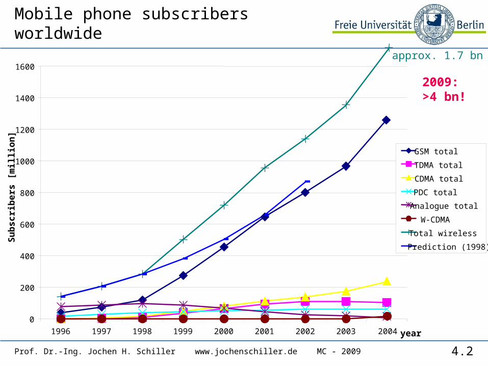
Mobile phone subscribers worldwide
year
Su
bsc
rib
ers
[mill
ion
]
0
200
400
600
800
1000
1200
1400
1600
1996 1997 1998 1999 2000 2001 2002 2003 2004
approx. 1.7 bn
GSM total
TDMA total
CDMA total
PDC total
Analogue total
W-CDMA
Total wireless
Prediction (1998)
2009:>4 bn!
4.3Prof. Dr.-Ing. Jochen H. Schiller www.jochenschiller.de MC - 2009
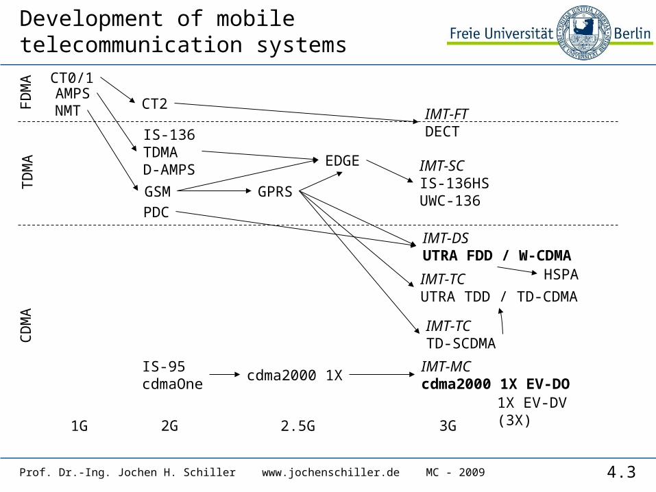
Development of mobile telecommunication systems
1G 2G 3G2.5G
IS-95cdmaOne
IS-136TDMAD-AMPS
GSM
PDC
GPRS
IMT-DSUTRA FDD / W-CDMA
EDGE
IMT-TCUTRA TDD / TD-CDMA
cdma2000 1X
1X EV-DV(3X)
AMPSNMT
IMT-SCIS-136HSUWC-136
IMT-TCTD-SCDMA
CT0/1
CT2IMT-FTDECT
CD
MA
TD
MA
FD
MA
IMT-MCcdma2000 1X EV-DO
HSPA
4.4
Some press news…
• 16th April 2008: The GSMA, the global trade group for the mobile industry, today announced that total connections to GSM mobile communications networks have now passed the 3 Billion mark globally. The third billion landmark has been reached just four years after the GSM industry surpassed its first billion, and just two years from the second billionth connection. The 3 Billion landmark has been surpassed just 17 years after the first GSM network launch in 1991. Today more than 700 mobile operators across 218 countries and territories of the world are adding new connections at the rate of 15 per second, or 1.3 million per day.
• 11 February 2009: The GSMA today announced that the mobile world has celebrated its four billionth connection, according to Wireless Intelligence, the GSMA’s market intelligence unit. This milestone underscores the continued strong growth of the mobile industry and puts the global market on the path to reach a staggering six billion connections by 2013.
• Check out www.gsmworld.com for more!
Prof. Dr.-Ing. Jochen H. Schiller www.jochenschiller.de MC - 2009
4.5Prof. Dr.-Ing. Jochen H. Schiller www.jochenschiller.de MC - 2009
How does it work?
• How can the system locate a user?
• Why don’t all phones ring at the same time?
• What happens if two users talksimultaneously?
• Why don’t I get the bill from my neighbor?
• Why can an Australian use her phone inBerlin?
• Why can’t I simply overhear the neighbor’s communication?
• How secure is the mobile phone system?
• What are the key components of the mobile phone network?
4.6Prof. Dr.-Ing. Jochen H. Schiller www.jochenschiller.de MC - 2009
GSM: Overview
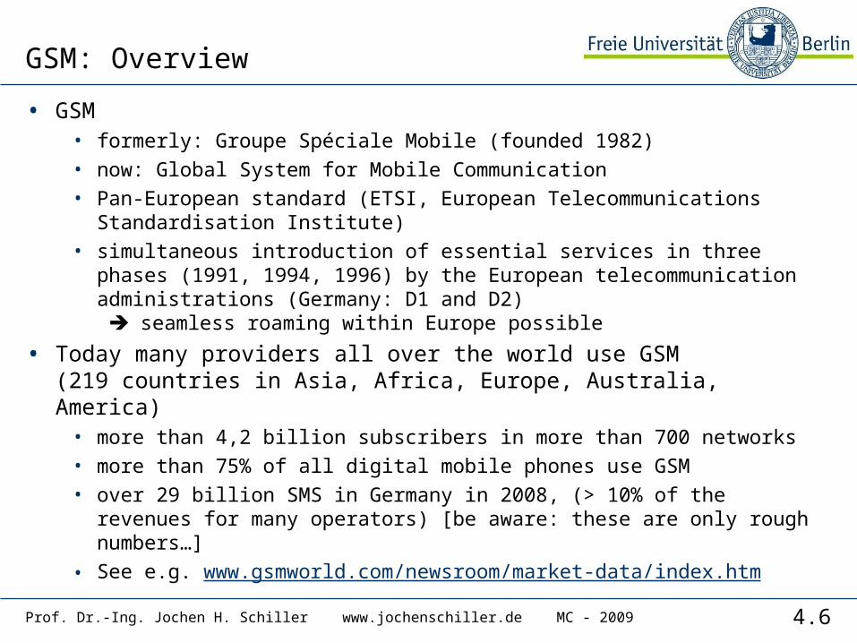
• GSM• formerly: Groupe Spéciale Mobile (founded 1982)• now: Global System for Mobile Communication• Pan-European standard (ETSI, European Telecommunications
Standardisation Institute)• simultaneous introduction of essential services in three phases
(1991, 1994, 1996) by the European telecommunication administrations (Germany: D1 and D2) seamless roaming within Europe possible
• Today many providers all over the world use GSM(219 countries in Asia, Africa, Europe, Australia, America)
• more than 4,2 billion subscribers in more than 700 networks• more than 75% of all digital mobile phones use GSM• over 29 billion SMS in Germany in 2008, (> 10% of the revenues
for many operators) [be aware: these are only rough numbers…]• See e.g. www.gsmworld.com/newsroom/market-data/index.htm
4.7Prof. Dr.-Ing. Jochen H. Schiller www.jochenschiller.de MC - 2009
Performance characteristics of GSM (wrt. analog sys.)
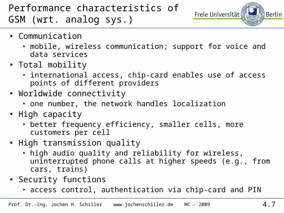
• Communication • mobile, wireless communication; support for voice and data
services
• Total mobility • international access, chip-card enables use of access points
of different providers
• Worldwide connectivity• one number, the network handles localization
• High capacity • better frequency efficiency, smaller cells, more customers
per cell
• High transmission quality• high audio quality and reliability for wireless, uninterrupted
phone calls at higher speeds (e.g., from cars, trains)
• Security functions • access control, authentication via chip-card and PIN
4.8Prof. Dr.-Ing. Jochen H. Schiller www.jochenschiller.de MC - 2009
Disadvantages of GSM
• There is no perfect system!!• no end-to-end encryption of user data• no full ISDN bandwidth of 64 kbit/s to the user, no
transparent B-channel
• reduced concentration while driving
• electromagnetic radiation
• abuse of private data possible
• roaming profiles accessible
• high complexity of the system
• several incompatibilities within the GSM standards

4.9Prof. Dr.-Ing. Jochen H. Schiller www.jochenschiller.de MC - 2009
GSM: Mobile Services
• GSM offers• several types of connections
• voice connections, data connections, short message service
• multi-service options (combination of basic services)
• Three service domains• Bearer Services• Telematic Services• Supplementary Services
GSM-PLMNtransit
network(PSTN, ISDN)
source/destination
networkTE TE
bearer services
tele services
R, S (U, S, R)Um
MT
MS
4.10Prof. Dr.-Ing. Jochen H. Schiller www.jochenschiller.de MC - 2009
Bearer Services
• Telecommunication services to transfer data between access points
• Specification of services up to the terminal interface (OSI layers 1-3)
• Different data rates for voice and data (original standard)• data service (circuit switched)
• synchronous: 2.4, 4.8 or 9.6 kbit/s• asynchronous: 300 - 1200 bit/s
• data service (packet switched)• synchronous: 2.4, 4.8 or 9.6 kbit/s• asynchronous: 300 - 9600 bit/s
• Today: data rates of approx. 50 kbit/s possible – will be covered later! (even more with new modulation)

4.11Prof. Dr.-Ing. Jochen H. Schiller www.jochenschiller.de MC - 2009
Tele Services I
• Telecommunication services that enable voice communication via mobile phones
• All these basic services have to obey cellular functions, security measurements etc.
• Offered services• mobile telephony
primary goal of GSM was to enable mobile telephony offering the traditional bandwidth of 3.1 kHz
• Emergency numbercommon number throughout Europe (112); mandatory for all service providers; free of charge; connection with the highest priority (preemption of other connections possible)
• Multinumberingseveral ISDN phone numbers per user possible
4.12Prof. Dr.-Ing. Jochen H. Schiller www.jochenschiller.de MC - 2009
Tele Services II
• Additional services• Non-Voice-Teleservices
• group 3 fax• voice mailbox (implemented in the fixed network supporting the
mobile terminals)• electronic mail (MHS, Message Handling System, implemented
in the fixed network)• ...
• Short Message Service (SMS)alphanumeric data transmission to/from the mobile terminal (160 characters) using the signaling channel, thus allowing simultaneous use of basic services and SMS(almost ignored in the beginning now the most successful add-on!)
4.13Prof. Dr.-Ing. Jochen H. Schiller www.jochenschiller.de MC - 2009
Supplementary services
• Services in addition to the basic services, cannot be offered stand-alone
• Similar to ISDN services besides lower bandwidth due to the radio link
• May differ between different service providers, countries and protocol versions
• Important services• identification: forwarding of caller number• suppression of number forwarding• automatic call-back• conferencing with up to 7 participants• locking of the mobile terminal (incoming or outgoing calls)• ...
4.14Prof. Dr.-Ing. Jochen H. Schiller www.jochenschiller.de MC - 2009
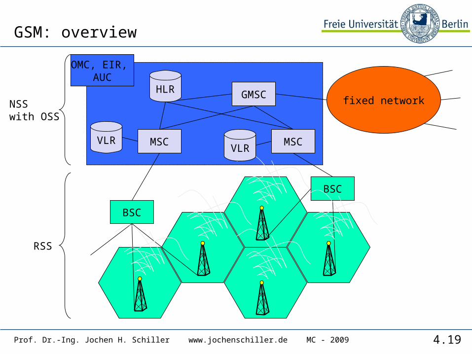
Architecture of the GSM system
• GSM is a PLMN (Public Land Mobile Network)• several providers setup mobile networks following the GSM
standard within each country• components
• MS (mobile station)• BS (base station)• MSC (mobile switching center)• LR (location register)
• subsystems• RSS (radio subsystem): covers all radio aspects• NSS (network and switching subsystem): call forwarding,
handover, switching• OSS (operation subsystem): management of the network
4.15Prof. Dr.-Ing. Jochen H. Schiller www.jochenschiller.de MC - 2009
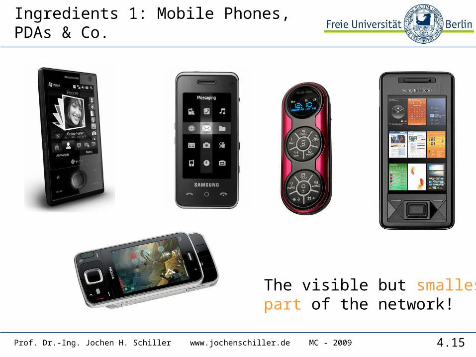
Ingredients 1: Mobile Phones, PDAs & Co.
The visible but smallestpart of the network!
4.16Prof. Dr.-Ing. Jochen H. Schiller www.jochenschiller.de MC - 2009
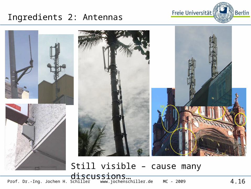
Ingredients 2: Antennas
Still visible – cause many discussions…

4.17Prof. Dr.-Ing. Jochen H. Schiller www.jochenschiller.de MC - 2009
Ingredients 3: Infrastructure 1Base Stations
Cabling
Microwave links
4.18Prof. Dr.-Ing. Jochen H. Schiller www.jochenschiller.de MC - 2009
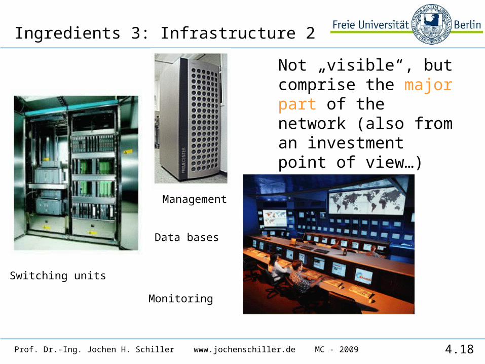
Ingredients 3: Infrastructure 2
Switching units
Data bases
Management
Monitoring
Not „visible“, but comprise the major part of the network (also from an investment point of view…)
4.19Prof. Dr.-Ing. Jochen H. Schiller www.jochenschiller.de MC - 2009
GSM: overview
fixed network
BSC
BSC
MSC MSC
GMSC
OMC, EIR, AUC
VLR
HLR
NSSwith OSS
RSS
VLR

4.20Prof. Dr.-Ing. Jochen H. Schiller www.jochenschiller.de MC - 2009
GSM: elements and interfaces
NSS
MS MS
BTS
BSC
GMSC
IWF
OMC
BTS
BSC
MSC MSC
Abis
Um
EIR
HLR
VLR VLR
A
BSS
PDN
ISDN, PSTN
RSS
radio cell
radio cell
MS
AUCOSS
signaling
O
4.21Prof. Dr.-Ing. Jochen H. Schiller www.jochenschiller.de MC - 2009
Um
Abis
ABSS
radiosubsystem
MS MS
BTSBSC
BTS
BTSBSC
BTS
network and switching subsystem
MSC
MSC
fixedpartner networks
IWF
ISDNPSTN
PSPDNCSPDN
SS
7
EIR
HLR
VLR
ISDNPSTN
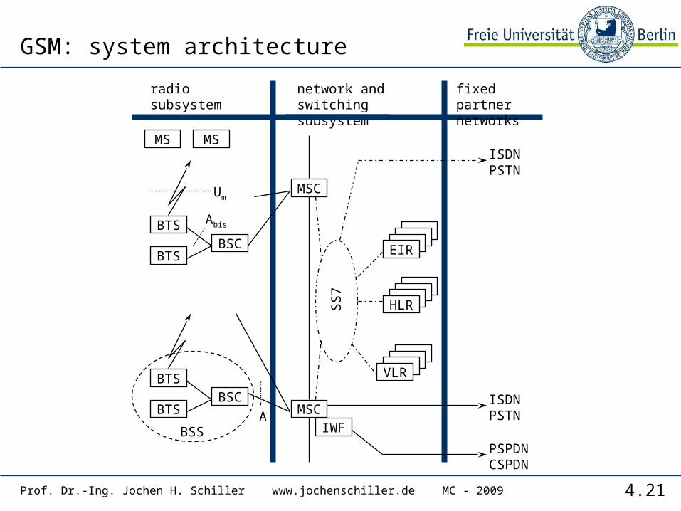
GSM: system architecture
4.22Prof. Dr.-Ing. Jochen H. Schiller www.jochenschiller.de MC - 2009
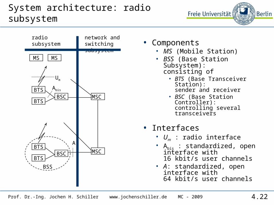
System architecture: radio subsystem
• Components• MS (Mobile Station)• BSS (Base Station Subsystem):
consisting of• BTS (Base Transceiver
Station):sender and receiver
• BSC (Base Station Controller):controlling several transceivers
• Interfaces• Um : radio interface• Abis : standardized, open
interface with 16 kbit/s user channels
• A: standardized, open interface with 64 kbit/s user channels
Um
Abis
A
BSS
radiosubsystem
network and switchingsubsystem
MS MS
BTSBSC MSC
BTS
BTSBSC
BTSMSC
4.23Prof. Dr.-Ing. Jochen H. Schiller www.jochenschiller.de MC - 2009
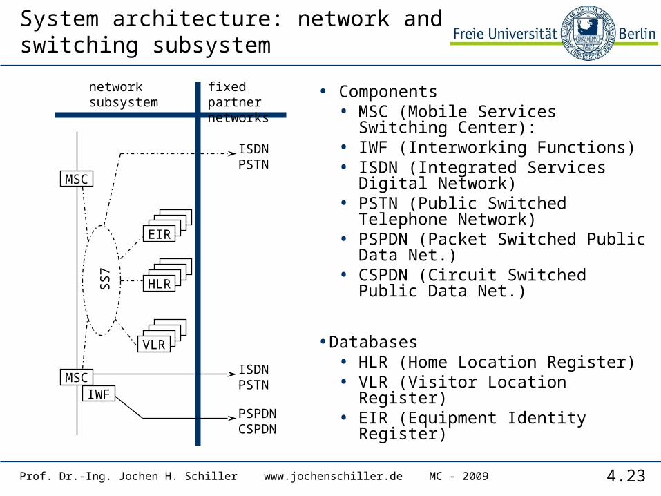
System architecture: network and switching subsystem
• Components• MSC (Mobile Services Switching
Center):• IWF (Interworking Functions)• ISDN (Integrated Services Digital
Network)• PSTN (Public Switched Telephone
Network)• PSPDN (Packet Switched Public
Data Net.)• CSPDN (Circuit Switched Public
Data Net.)
•Databases• HLR (Home Location Register)• VLR (Visitor Location Register)• EIR (Equipment Identity Register)
networksubsystem
MSC
MSC
fixed partnernetworks
IWF
ISDNPSTN
PSPDNCSPDN
SS
7
EIR
HLR
VLR
ISDNPSTN
4.24Prof. Dr.-Ing. Jochen H. Schiller www.jochenschiller.de MC - 2009
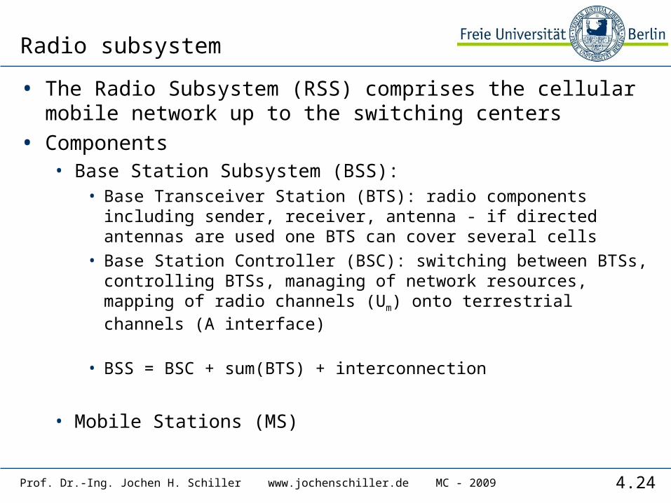
Radio subsystem
• The Radio Subsystem (RSS) comprises the cellular mobile network up to the switching centers
• Components• Base Station Subsystem (BSS):
• Base Transceiver Station (BTS): radio components including sender, receiver, antenna - if directed antennas are used one BTS can cover several cells
• Base Station Controller (BSC): switching between BTSs, controlling BTSs, managing of network resources, mapping of radio channels (Um) onto terrestrial channels (A interface)
• BSS = BSC + sum(BTS) + interconnection
• Mobile Stations (MS)
4.25Prof. Dr.-Ing. Jochen H. Schiller www.jochenschiller.de MC - 2009
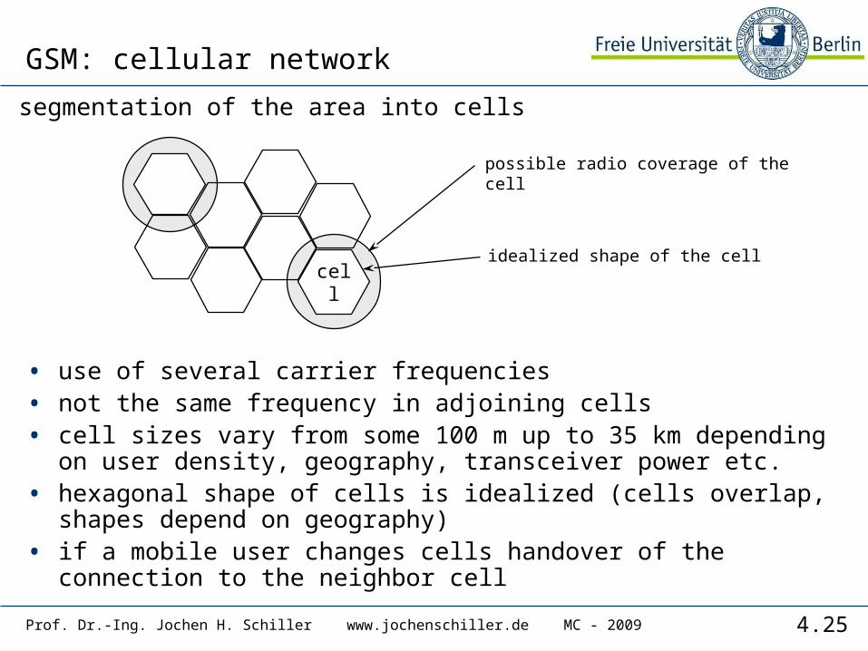
possible radio coverage of the cell
idealized shape of the cellcell
segmentation of the area into cells
GSM: cellular network
• use of several carrier frequencies• not the same frequency in adjoining cells• cell sizes vary from some 100 m up to 35 km depending on user
density, geography, transceiver power etc.• hexagonal shape of cells is idealized (cells overlap, shapes
depend on geography)• if a mobile user changes cells handover of the connection to the
neighbor cell
4.26Prof. Dr.-Ing. Jochen H. Schiller www.jochenschiller.de MC - 2009
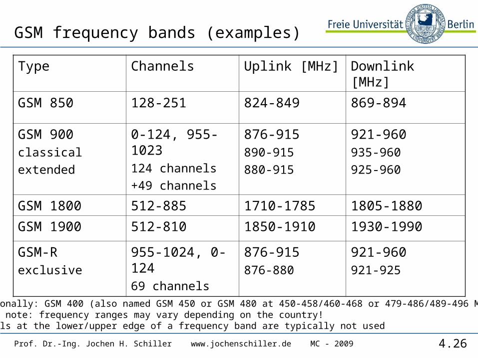
GSM frequency bands (examples)
Type Channels Uplink [MHz] Downlink [MHz]
GSM 850 128-251 824-849 869-894
GSM 900classicalextended
0-124, 955-1023124 channels+49 channels
876-915890-915880-915
921-960935-960925-960
GSM 1800 512-885 1710-1785 1805-1880
GSM 1900 512-810 1850-1910 1930-1990
GSM-Rexclusive
955-1024, 0-12469 channels
876-915876-880
921-960921-925
- Additionally: GSM 400 (also named GSM 450 or GSM 480 at 450-458/460-468 or 479-486/489-496 MHz)- Please note: frequency ranges may vary depending on the country!- Channels at the lower/upper edge of a frequency band are typically not used
4.27Prof. Dr.-Ing. Jochen H. Schiller www.jochenschiller.de MC - 2009
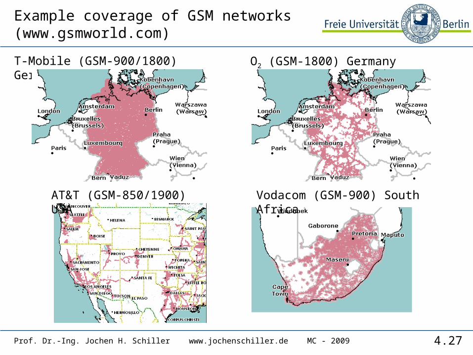
Example coverage of GSM networks (www.gsmworld.com)
T-Mobile (GSM-900/1800) Germany O2 (GSM-1800) Germany
AT&T (GSM-850/1900) USA Vodacom (GSM-900) South Africa
4.28Prof. Dr.-Ing. Jochen H. Schiller www.jochenschiller.de MC - 2009
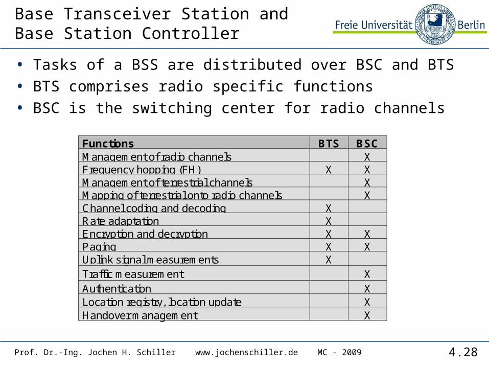
Base Transceiver Station and Base Station Controller
• Tasks of a BSS are distributed over BSC and BTS
• BTS comprises radio specific functions
• BSC is the switching center for radio channels
Functions BTS BSCManagement of radio channels XFrequency hopping (FH) X XManagement of terrestrial channels XMapping of terrestrial onto radio channels XChannel coding and decoding XRate adaptation XEncryption and decryption X XPaging X XUplink signal measurements XTraffic measurement XAuthentication XLocation registry, location update XHandover management X

4.29Prof. Dr.-Ing. Jochen H. Schiller www.jochenschiller.de MC - 2009
Mobile station
• Terminal for the use of GSM services
• A mobile station (MS) comprises several functional groups• MT (Mobile Terminal):
• offers common functions used by all services the MS offers• corresponds to the network termination (NT) of an ISDN access• end-point of the radio interface (Um)
• TA (Terminal Adapter):• terminal adaptation, hides radio specific characteristics
• TE (Terminal Equipment):• peripheral device of the MS, offers services to a user• does not contain GSM specific functions
• SIM (Subscriber Identity Module):• personalization of the mobile terminal, stores user parameters
R SUm
TE TA MT

4.30Prof. Dr.-Ing. Jochen H. Schiller www.jochenschiller.de MC - 2009
Network and switching subsystem
• NSS is the main component of the public mobile network GSM• switching, mobility management, interconnection to other
networks, system control
• Components• Mobile Services Switching Center (MSC)
controls all connections via a separated network to/from a mobile terminal within the domain of the MSC - several BSC can belong to a MSC
• Databases (important: scalability, high capacity, low delay)• Home Location Register (HLR)
central master database containing user data, permanent and semi-permanent data of all subscribers assigned to the HLR (one provider can have several HLRs)
• Visitor Location Register (VLR)local database for a subset of user data, including data about all user currently in the domain of the VLR
4.31Prof. Dr.-Ing. Jochen H. Schiller www.jochenschiller.de MC - 2009
Mobile Services Switching Center
• The MSC (mobile services switching center) plays a central role in GSM
• switching functions• additional functions for mobility support• management of network resources• interworking functions via Gateway MSC (GMSC)• integration of several databases
• Functions of a MSC• specific functions for paging and call forwarding• termination of SS7 (signaling system no. 7)• mobility specific signaling• location registration and forwarding of location information• provision of new services (fax, data calls)• support of short message service (SMS)• generation and forwarding of accounting and billing information
4.32Prof. Dr.-Ing. Jochen H. Schiller www.jochenschiller.de MC - 2009
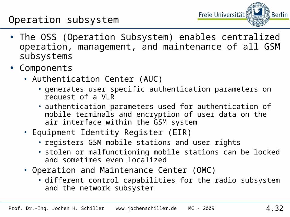
Operation subsystem
• The OSS (Operation Subsystem) enables centralized operation, management, and maintenance of all GSM subsystems
• Components• Authentication Center (AUC)
• generates user specific authentication parameters on request of a VLR
• authentication parameters used for authentication of mobile terminals and encryption of user data on the air interface within the GSM system
• Equipment Identity Register (EIR)• registers GSM mobile stations and user rights• stolen or malfunctioning mobile stations can be locked and
sometimes even localized• Operation and Maintenance Center (OMC)
• different control capabilities for the radio subsystem and the network subsystem

4.33Prof. Dr.-Ing. Jochen H. Schiller www.jochenschiller.de MC - 2009
1 2 3 4 5 6 7 8
higher GSM frame structures
935-960 MHz124 channels (200 kHz)downlink
890-915 MHz124 channels (200 kHz)uplink
frequ
ency
time
GSM TDMA frame
GSM time-slot (normal burst)
4.615 ms
546.5 µs577 µs
tail user data TrainingSguardspace S user data tail
guardspace
3 bits 57 bits 26 bits 57 bits1 1 3
GSM - TDMA/FDMA
4.34Prof. Dr.-Ing. Jochen H. Schiller www.jochenschiller.de MC - 2009
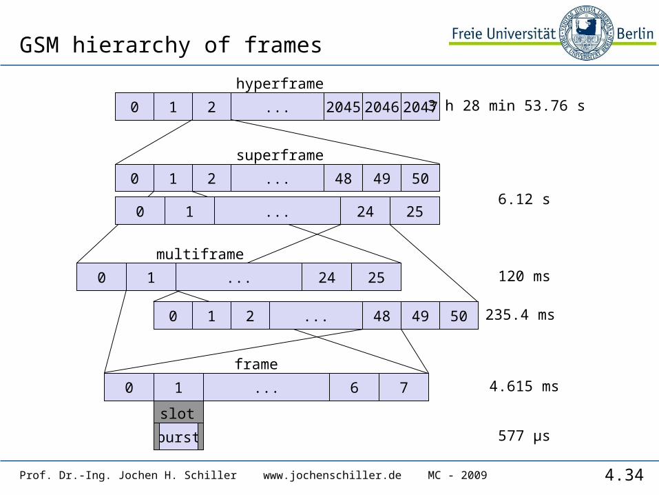
GSM hierarchy of frames
0 1 2 2045 2046 2047...
hyperframe
0 1 2 48 49 50...
0 1 24 25...
superframe
0 1 24 25...
0 1 2 48 49 50...
0 1 6 7...
multiframe
frame
burst
slot
577 µs
4.615 ms
120 ms
235.4 ms
6.12 s
3 h 28 min 53.76 s
4.35Prof. Dr.-Ing. Jochen H. Schiller www.jochenschiller.de MC - 2009
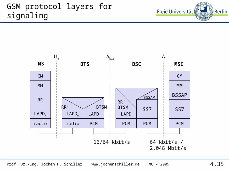
GSM protocol layers for signaling
CM
MM
RR
MM
LAPDm
radio
LAPDm
radio
LAPD
PCM
RR’ BTSM
CM
LAPD
PCM
RR’BTSM
16/64 kbit/s
Um Abis A
SS7
PCM
SS7
PCM
64 kbit/s /2.048 Mbit/s
MS BTS BSC MSC
BSSAP BSSAP
4.36Prof. Dr.-Ing. Jochen H. Schiller www.jochenschiller.de MC - 2009
Mobile Terminated Call
PSTNcallingstation
GMSC
HLR VLR
BSSBSSBSS
MSC
MS
1 2
3
4
5
6
7
8 9
10
11 12
1316
10 10
11 11 11
14 15
17
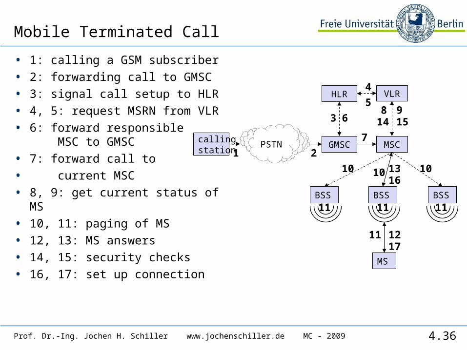
• 1: calling a GSM subscriber
• 2: forwarding call to GMSC
• 3: signal call setup to HLR
• 4, 5: request MSRN from VLR
• 6: forward responsible MSC to GMSC
• 7: forward call to
• current MSC
• 8, 9: get current status of MS
• 10, 11: paging of MS
• 12, 13: MS answers
• 14, 15: security checks
• 16, 17: set up connection
4.37Prof. Dr.-Ing. Jochen H. Schiller www.jochenschiller.de MC - 2009
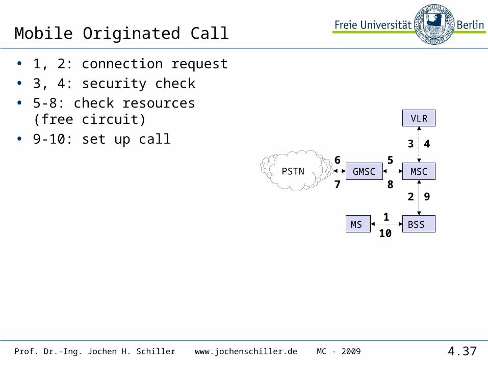
Mobile Originated Call
• 1, 2: connection request
• 3, 4: security check
• 5-8: check resources (free circuit)
• 9-10: set up call
PSTN GMSC
VLR
BSS
MSC
MS1
2
6 5
3 4
9
10
7 8
4.38Prof. Dr.-Ing. Jochen H. Schiller www.jochenschiller.de MC - 2009
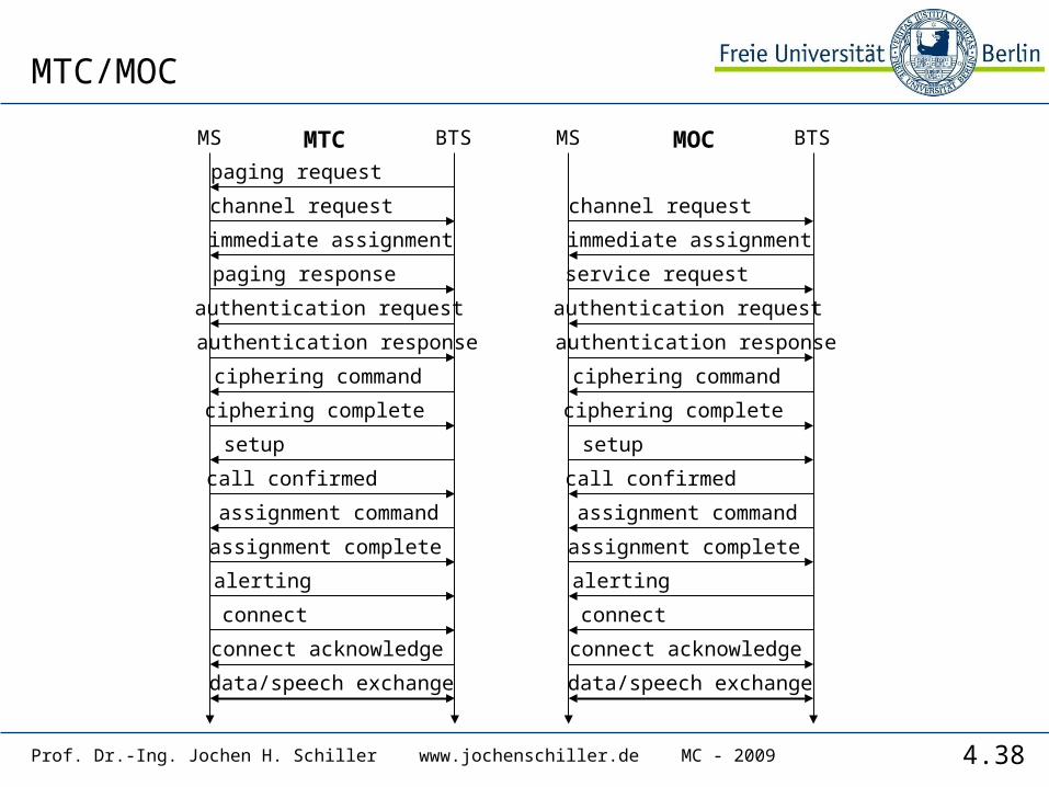
MTC/MOC
BTSMS
paging request
channel request
immediate assignment
paging response
authentication request
authentication response
ciphering command
ciphering complete
setup
call confirmed
assignment command
assignment complete
alerting
connect
connect acknowledge
data/speech exchange
BTSMS
channel request
immediate assignment
service request
authentication request
authentication response
ciphering command
ciphering complete
setup
call confirmed
assignment command
assignment complete
alerting
connect
connect acknowledge
data/speech exchange
MTC MOC
4.39Prof. Dr.-Ing. Jochen H. Schiller www.jochenschiller.de MC - 2009
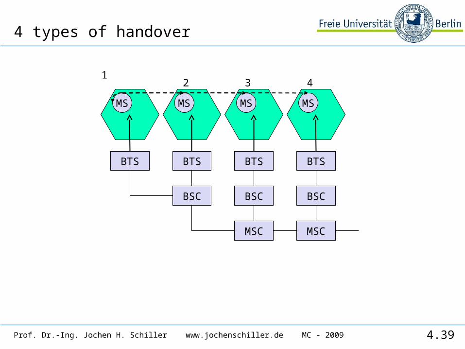
4 types of handover
MSC MSC
BSC BSCBSC
BTS BTS BTSBTS
MS MS MS MS
12 3 4
4.40Prof. Dr.-Ing. Jochen H. Schiller www.jochenschiller.de MC - 2009
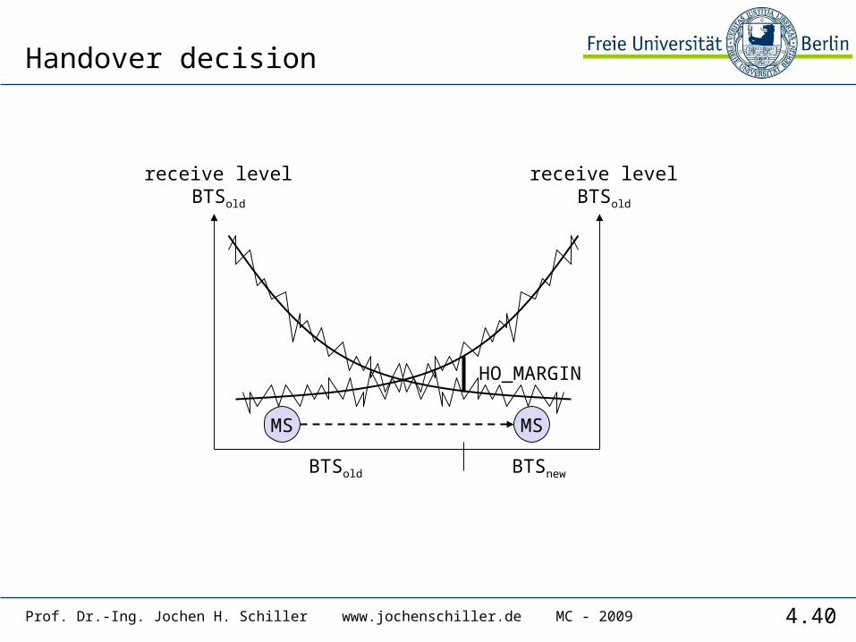
Handover decision
receive levelBTSold
receive levelBTSold
MS MS
HO_MARGIN
BTSold BTSnew
4.41Prof. Dr.-Ing. Jochen H. Schiller www.jochenschiller.de MC - 2009
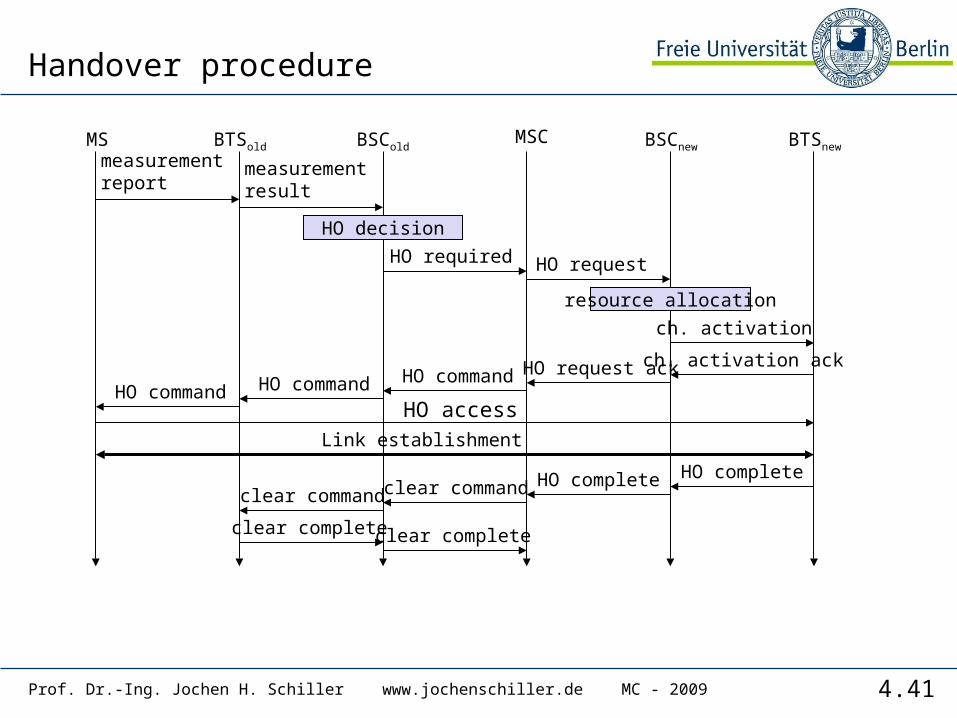
Handover procedure
HO access
BTSold BSCnew
measurementresult
BSCold
Link establishment
MSCMSmeasurementreport
HO decision
HO required
BTSnew
HO request
resource allocation
ch. activation
ch. activation ackHO request ackHO commandHO commandHO command
HO completeHO completeclear commandclear command
clear complete clear complete
4.42Prof. Dr.-Ing. Jochen H. Schiller www.jochenschiller.de MC - 2009
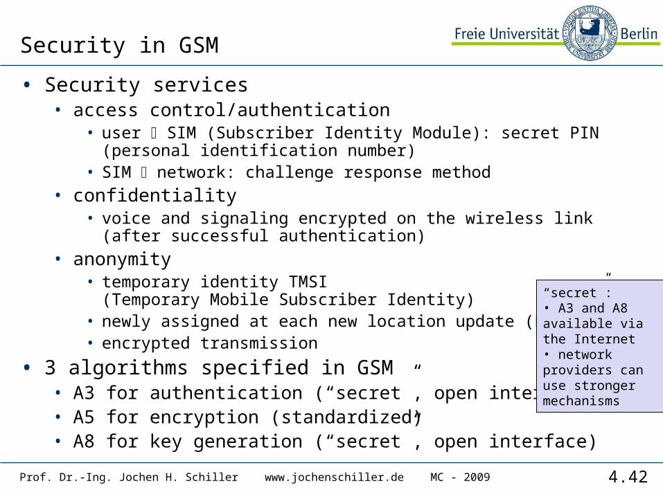
Security in GSM
• Security services• access control/authentication
• user SIM (Subscriber Identity Module): secret PIN (personal identification number)
• SIM network: challenge response method• confidentiality
• voice and signaling encrypted on the wireless link (after successful authentication)
• anonymity• temporary identity TMSI
(Temporary Mobile Subscriber Identity)• newly assigned at each new location update (LUP)• encrypted transmission
• 3 algorithms specified in GSM• A3 for authentication (“secret”, open interface)• A5 for encryption (standardized)• A8 for key generation (“secret”, open interface)
“secret”:• A3 and A8 available via the Internet• network providers can use stronger mechanisms

4.43Prof. Dr.-Ing. Jochen H. Schiller www.jochenschiller.de MC - 2009
GSM - authentication
A3
RANDKi
128 bit 128 bit
SRES* 32 bit
A3
RAND Ki
128 bit 128 bit
SRES 32 bit
SRES* =? SRES SRES
RAND
SRES32 bit
mobile network SIM
AC
MSC
SIM
Ki: individual subscriber authentication key SRES: signed response

4.44Prof. Dr.-Ing. Jochen H. Schiller www.jochenschiller.de MC - 2009
GSM - key generation and encryption
A8
RANDKi
128 bit 128 bit
Kc
64 bit
A8
RAND Ki
128 bit 128 bit
SRES
RAND
encrypteddata
mobile network (BTS) MS with SIM
AC
BSS
SIM
A5
Kc
64 bit
A5
MSdata data
cipherkey

4.45Prof. Dr.-Ing. Jochen H. Schiller www.jochenschiller.de MC - 2009
Data services in GSM I
• Data transmission standardized with only 9.6 kbit/s• advanced coding allows 14.4 kbit/s• not enough for Internet and multimedia applications
• HSCSD (High-Speed Circuit Switched Data)• mainly software update• bundling of several time-slots to get higher AIUR (Air
Interface User Rate, e.g., 57.6 kbit/s using 4 slots @ 14.4)• advantage: ready to use, constant quality, simple• disadvantage: channels blocked for voice transmission
AIUR [kbit/s] TCH/F4.8 TCH/F9.6 TCH/F14.44.8 19.6 2 1
14.4 3 119.2 4 228.8 3 238.4 443.2 357.6 4
4.46Prof. Dr.-Ing. Jochen H. Schiller www.jochenschiller.de MC - 2009
Data services in GSM II
• GPRS (General Packet Radio Service)• packet switching• using free slots only if data packets ready to send
(e.g., 50 kbit/s using 4 slots temporarily)• standardization 1998, introduction 2001• advantage: one step towards UMTS, more flexible• disadvantage: more investment needed (new hardware)
• GPRS network elements• GSN (GPRS Support Nodes): GGSN and SGSN• GGSN (Gateway GSN)
• interworking unit between GPRS and PDN (Packet Data Network)• SGSN (Serving GSN)
• supports the MS (location, billing, security)• GR (GPRS Register)
• user addresses
4.47Prof. Dr.-Ing. Jochen H. Schiller www.jochenschiller.de MC - 2009
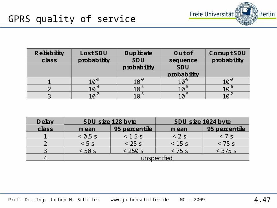
GPRS quality of service
Reliabilityclass
Lost SDUprobability
DuplicateSDU
probability
Out ofsequence
SDUprobability
Corrupt SDUprobability
1 10-9 10-9 10-9 10-9
2 10-4 10-5 10-5 10-6
3 10-2 10-5 10-5 10-2
Delay SDU size 128 byte SDU size 1024 byteclass mean 95 percentile mean 95 percentile
1 < 0.5 s < 1.5 s < 2 s < 7 s2 < 5 s < 25 s < 15 s < 75 s3 < 50 s < 250 s < 75 s < 375 s4 unspecified
4.48Prof. Dr.-Ing. Jochen H. Schiller www.jochenschiller.de MC - 2009
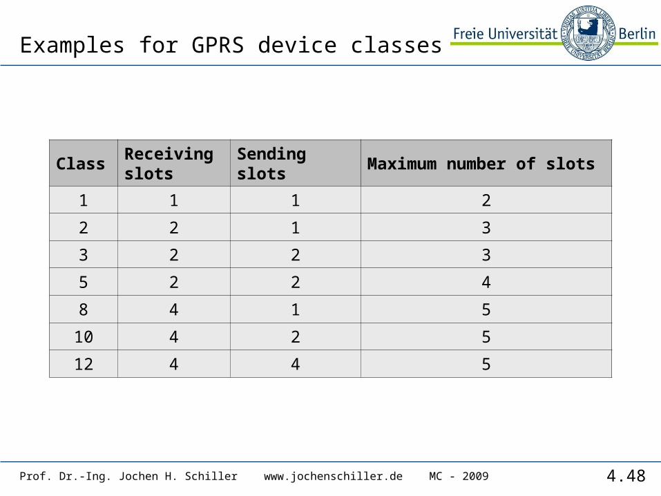
Examples for GPRS device classes
ClassReceiving slots
Sending slots
Maximum number of slots
1 1 1 2
2 2 1 3
3 2 2 3
5 2 2 4
8 4 1 5
10 4 2 5
12 4 4 5
4.49Prof. Dr.-Ing. Jochen H. Schiller www.jochenschiller.de MC - 2009
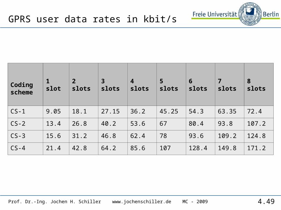
GPRS user data rates in kbit/s
Coding scheme
1 slot 2 slots 3 slots 4 slots 5 slots 6 slots 7 slots 8 slots
CS-1 9.05 18.1 27.15 36.2 45.25 54.3 63.35 72.4
CS-2 13.4 26.8 40.2 53.6 67 80.4 93.8 107.2
CS-3 15.6 31.2 46.8 62.4 78 93.6 109.2 124.8
CS-4 21.4 42.8 64.2 85.6 107 128.4 149.8 171.2
4.50Prof. Dr.-Ing. Jochen H. Schiller www.jochenschiller.de MC - 2009
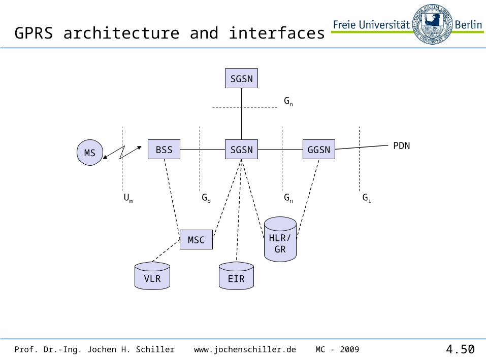
GPRS architecture and interfaces
MS BSS GGSNSGSN
MSC
Um
EIR
HLR/GR
VLR
PDN
Gb Gn Gi
SGSN
Gn
4.51Prof. Dr.-Ing. Jochen H. Schiller www.jochenschiller.de MC - 2009
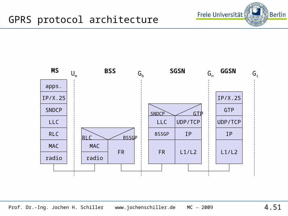
GPRS protocol architecture
apps.
IP/X.25
LLC
GTP
MAC
radio
MAC
radioFR
RLC BSSGP
IP/X.25
FR
Um Gb Gn
L1/L2 L1/L2
MS BSS SGSN GGSN
UDP/TCP
Gi
SNDCP
RLC BSSGP IP IP
LLC UDP/TCP
SNDCP GTP
4.52Prof. Dr.-Ing. Jochen H. Schiller www.jochenschiller.de MC - 2009
DECT
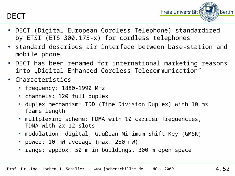
• DECT (Digital European Cordless Telephone) standardized by ETSI (ETS 300.175-x) for cordless telephones
• standard describes air interface between base-station and mobile phone
• DECT has been renamed for international marketing reasons into „Digital Enhanced Cordless Telecommunication“
• Characteristics• frequency: 1880-1990 MHz• channels: 120 full duplex• duplex mechanism: TDD (Time Division Duplex) with 10 ms frame
length• multplexing scheme: FDMA with 10 carrier frequencies,
TDMA with 2x 12 slots• modulation: digital, Gaußian Minimum Shift Key (GMSK)• power: 10 mW average (max. 250 mW)• range: approx. 50 m in buildings, 300 m open space
4.53Prof. Dr.-Ing. Jochen H. Schiller www.jochenschiller.de MC - 2009
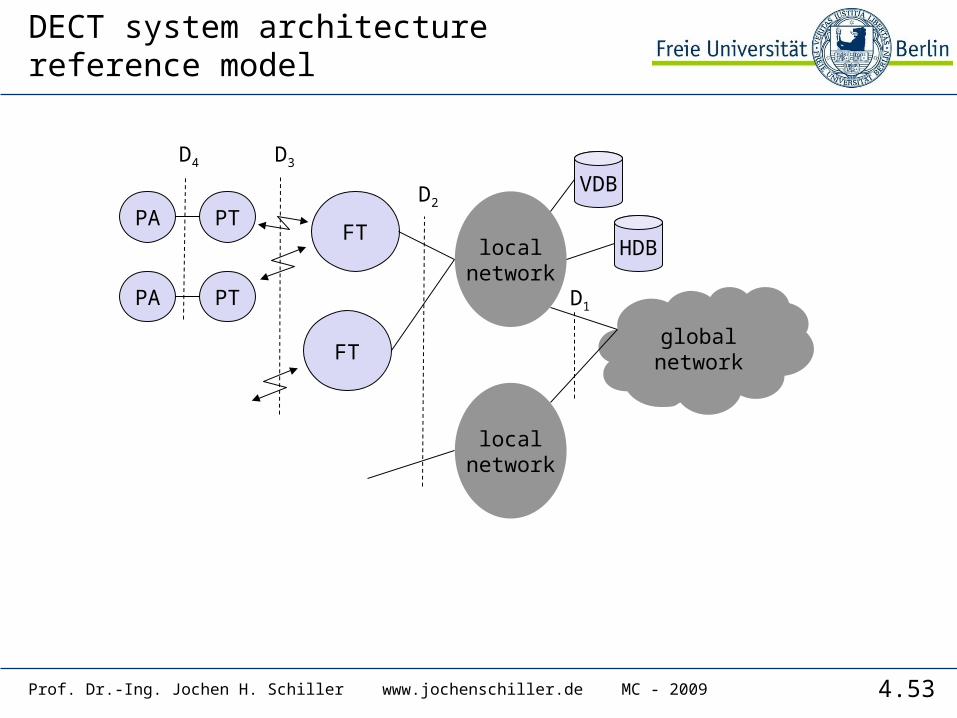
DECT system architecture reference model
globalnetwork
localnetwork
localnetwork
FT
FT
PTPA
PTPA
VDB
HDB
D1
D2
D3D4

4.54Prof. Dr.-Ing. Jochen H. Schiller www.jochenschiller.de MC - 2009
physical layer
medium access control
data linkcontrol
data linkcontrol
networklayer
OSI layer 1
OSI layer 2
OSI layer 3
U-PlaneC-Plane
signaling,interworking
applicationprocesses
DECT reference model
• close to the OSI reference model
• management plane over all layers
• several services in C(ontrol)- and U(ser)-plane
man
agem
ent
4.55Prof. Dr.-Ing. Jochen H. Schiller www.jochenschiller.de MC - 2009
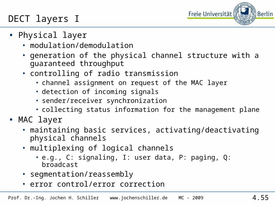
DECT layers I
• Physical layer• modulation/demodulation• generation of the physical channel structure with a
guaranteed throughput• controlling of radio transmission
• channel assignment on request of the MAC layer• detection of incoming signals• sender/receiver synchronization• collecting status information for the management plane
• MAC layer• maintaining basic services, activating/deactivating physical
channels• multiplexing of logical channels
• e.g., C: signaling, I: user data, P: paging, Q: broadcast• segmentation/reassembly• error control/error correction

4.56Prof. Dr.-Ing. Jochen H. Schiller www.jochenschiller.de MC - 2009
DECT time multiplex frame
slot
sync
A field
DATA
DATA64
C16
DATA64
C16
DATA64
C16
DATA64
C16
B field
D field
1 frame = 10 ms
12 down slots 12 up slots
0 419
0 31 0 387
0 63 0 319
protected mode
unprotected mode
simplex bearer
25.6 kbit/s
32 kbit/s
420 bit + 52 µs guard time („60 bit“) in 0.4167 ms
guard
X field 0 3
A: network controlB: user dataX: transmission quality
4.57Prof. Dr.-Ing. Jochen H. Schiller www.jochenschiller.de MC - 2009
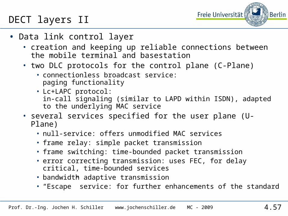
DECT layers II
• Data link control layer• creation and keeping up reliable connections between the
mobile terminal and basestation • two DLC protocols for the control plane (C-Plane)
• connectionless broadcast service:paging functionality
• Lc+LAPC protocol:in-call signaling (similar to LAPD within ISDN), adapted to the underlying MAC service
• several services specified for the user plane (U-Plane)• null-service: offers unmodified MAC services• frame relay: simple packet transmission• frame switching: time-bounded packet transmission• error correcting transmission: uses FEC, for delay critical, time-
bounded services• bandwidth adaptive transmission• “Escape” service: for further enhancements of the standard

4.58Prof. Dr.-Ing. Jochen H. Schiller www.jochenschiller.de MC - 2009
DECT layers III
• Network layer• similar to ISDN (Q.931) and GSM (04.08)• offers services to request, check, reserve, control, and
release resources at the basestation and mobile terminal • resources
• necessary for a wireless connection• necessary for the connection of the DECT system to the fixed
network
• main tasks• call control: setup, release, negotiation, control • call independent services: call forwarding, accounting, call
redirecting• mobility management: identity management, authentication,
management of the location register

4.59Prof. Dr.-Ing. Jochen H. Schiller www.jochenschiller.de MC - 2009
Enhancements of the standard
• Several „DECT Application Profiles“ in addition to the DECT specification• GAP (Generic Access Profile) standardized by ETSI in 1997
• assures interoperability between DECT equipment of different manufacturers (minimal requirements for voice communication)
• enhanced management capabilities through the fixed network: Cordless Terminal Mobility (CTM)
• DECT/GSM Interworking Profile (GIP): connection to GSM• ISDN Interworking Profiles (IAP, IIP): connection to ISDN• Radio Local Loop Access Profile (RAP): public telephone service• CTM Access Profile (CAP): support for user mobility
DECTbasestation
GAP
DECTCommonAir Interface
DECTPortable Part
fixed network
4.60Prof. Dr.-Ing. Jochen H. Schiller www.jochenschiller.de MC - 2009
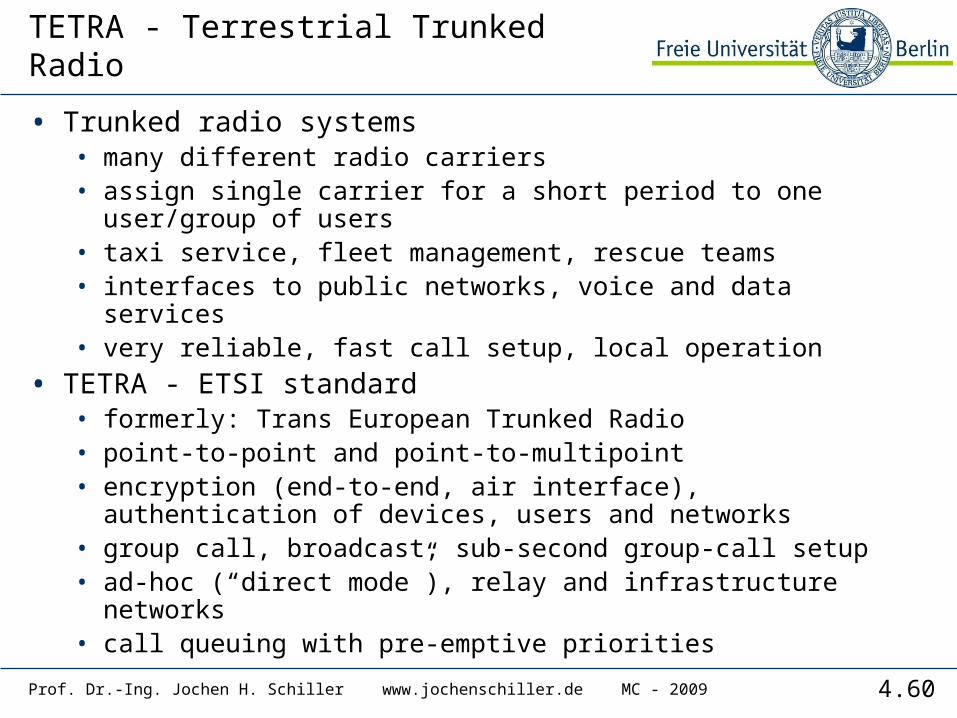
TETRA - Terrestrial Trunked Radio
• Trunked radio systems• many different radio carriers• assign single carrier for a short period to one user/group of
users• taxi service, fleet management, rescue teams• interfaces to public networks, voice and data services• very reliable, fast call setup, local operation
• TETRA - ETSI standard• formerly: Trans European Trunked Radio• point-to-point and point-to-multipoint• encryption (end-to-end, air interface), authentication of
devices, users and networks • group call, broadcast, sub-second group-call setup• ad-hoc (“direct mode”), relay and infrastructure networks• call queuing with pre-emptive priorities
4.61Prof. Dr.-Ing. Jochen H. Schiller www.jochenschiller.de MC - 2009
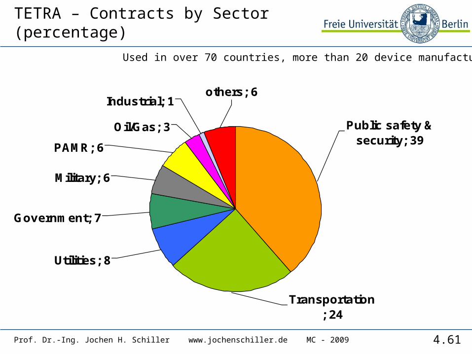
TETRA – Contracts by Sector (percentage)
Oil/Gas; 3
Industrial; 1others; 6
PAMR; 6
Military; 6
Government; 7
Utilities; 8
Transportation; 24
Public safety & security; 39
Used in over 70 countries, more than 20 device manufacturers
4.62Prof. Dr.-Ing. Jochen H. Schiller www.jochenschiller.de MC - 2009
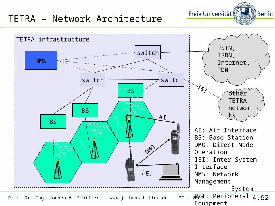
TETRA – Network Architecture
TETRA infrastructure
BS
BS
switch switch
switchNMS
BS
other TETRA networks
PSTN, ISDN,Internet, PDN
DMO
ISI
PEI
AI
AI: Air InterfaceBS: Base StationDMO: Direct Mode OperationISI: Inter-System InterfaceNMS: Network Management SystemPEI: Peripheral Equipment Interface

4.63Prof. Dr.-Ing. Jochen H. Schiller www.jochenschiller.de MC - 2009
TETRA – Direct Mode I
• Direct Mode enables ad-hoc operation and is one of the most important differences to pure infrastructure-based networks such as GSM, cdma2000 or UMTS.
Individual Call
Group Call
“Dual Watch” – alternating participation inInfrastructure and ad-hoc
network
Managed Direct Mode
network
Authorizingmobile station
4.64Prof. Dr.-Ing. Jochen H. Schiller www.jochenschiller.de MC - 2009
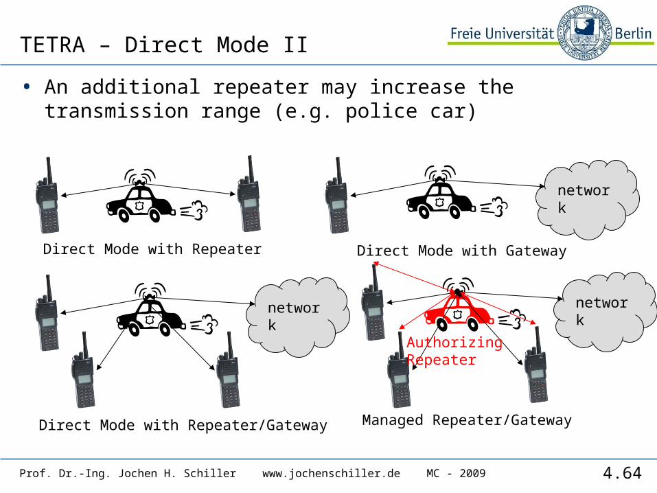
TETRA – Direct Mode II
• An additional repeater may increase the transmission range (e.g. police car)
Direct Mode with Gateway
network
Direct Mode with Repeater
Direct Mode with Repeater/Gateway
network
Managed Repeater/Gateway
network
AuthorizingRepeater
4.65Prof. Dr.-Ing. Jochen H. Schiller www.jochenschiller.de MC - 2009
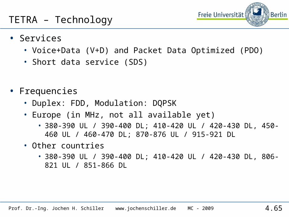
TETRA – Technology
• Services• Voice+Data (V+D) and Packet Data Optimized (PDO)• Short data service (SDS)
• Frequencies• Duplex: FDD, Modulation: DQPSK• Europe (in MHz, not all available yet)
• 380-390 UL / 390-400 DL; 410-420 UL / 420-430 DL, 450-460 UL / 460-470 DL; 870-876 UL / 915-921 DL
• Other countries• 380-390 UL / 390-400 DL; 410-420 UL / 420-430 DL, 806-821
UL / 851-866 DL
4.66Prof. Dr.-Ing. Jochen H. Schiller www.jochenschiller.de MC - 2009
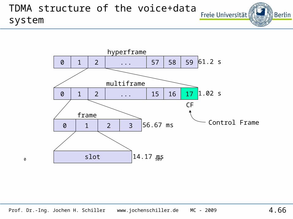
TDMA structure of the voice+data system
0 1 2 57 58 59...
hyperframe
0 1 2 15 16 17...
multiframe
0 1 2 3
0 slot 509
frame
14.17 ms
56.67 ms
1.02 s
61.2 s
CF
Control Frame
4.67Prof. Dr.-Ing. Jochen H. Schiller www.jochenschiller.de MC - 2009
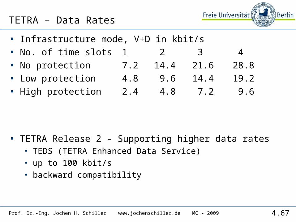
TETRA – Data Rates
• Infrastructure mode, V+D in kbit/s
• No. of time slots 1 2 3 4
• No protection 7.2 14.4 21.6 28.8
• Low protection 4.8 9.6 14.4 19.2
• High protection 2.4 4.8 7.2 9.6
• TETRA Release 2 – Supporting higher data rates• TEDS (TETRA Enhanced Data Service)• up to 100 kbit/s• backward compatibility
4.68Prof. Dr.-Ing. Jochen H. Schiller www.jochenschiller.de MC - 2009
UMTS and IMT-2000
• Proposals for IMT-2000 (International Mobile Telecommunications)• UWC-136, cdma2000, WP-CDMA• UMTS (Universal Mobile Telecommunications System) from ETSI
• UMTS• UTRA (was: UMTS, now: Universal Terrestrial Radio Access)• enhancements of GSM
• EDGE (Enhanced Data rates for GSM Evolution): GSM up to 384 kbit/s• CAMEL (Customized Application for Mobile Enhanced Logic)• VHE (virtual Home Environment)
• fits into GMM (Global Multimedia Mobility) initiative from ETSI• requirements
• min. 144 kbit/s rural (goal: 384 kbit/s)• min. 384 kbit/s suburban (goal: 512 kbit/s)• up to 2 Mbit/s urban

4.69Prof. Dr.-Ing. Jochen H. Schiller www.jochenschiller.de MC - 2009
Frequencies for IMT-2000
IMT-2000
1850 1900 1950 2000 2050 2100 2150 2200 MHz
MSS
ITU allocation(WRC 1992) IMT-2000
MSS
Europe
China
Japan
NorthAmerica
UTRAFDD
UTRAFDD
TDD
TDD
MSS
MSS
DECT
GSM1800
1850 1900 1950 2000 2050 2100 2150 2200 MHz
IMT-2000MSS
IMT-2000MSS
GSM1800
cdma2000W-CDMA
MSS
MSS
MSS
MSS
cdma2000W-CDMA
PHS
PCS rsv.
4.70Prof. Dr.-Ing. Jochen H. Schiller www.jochenschiller.de MC - 2009
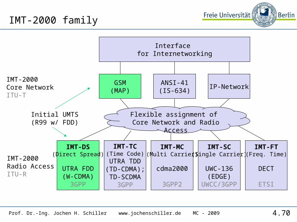
IMT-2000 family
IMT-DS(Direct Spread)
UTRA FDD(W-CDMA)
3GPP
IMT-TC(Time Code)UTRA TDD(TD-CDMA);TD-SCDMA
3GPP
IMT-MC(Multi Carrier)
cdma2000
3GPP2
IMT-SC(Single Carrier)
UWC-136(EDGE)
UWCC/3GPP
IMT-FT(Freq. Time)
DECT
ETSI
GSM(MAP)
ANSI-41(IS-634)
IP-NetworkIMT-2000Core NetworkITU-T
IMT-2000Radio AccessITU-R
Interface for Internetworking
Flexible assignment of Core Network and Radio Access
Initial UMTS(R99 w/ FDD)
4.71
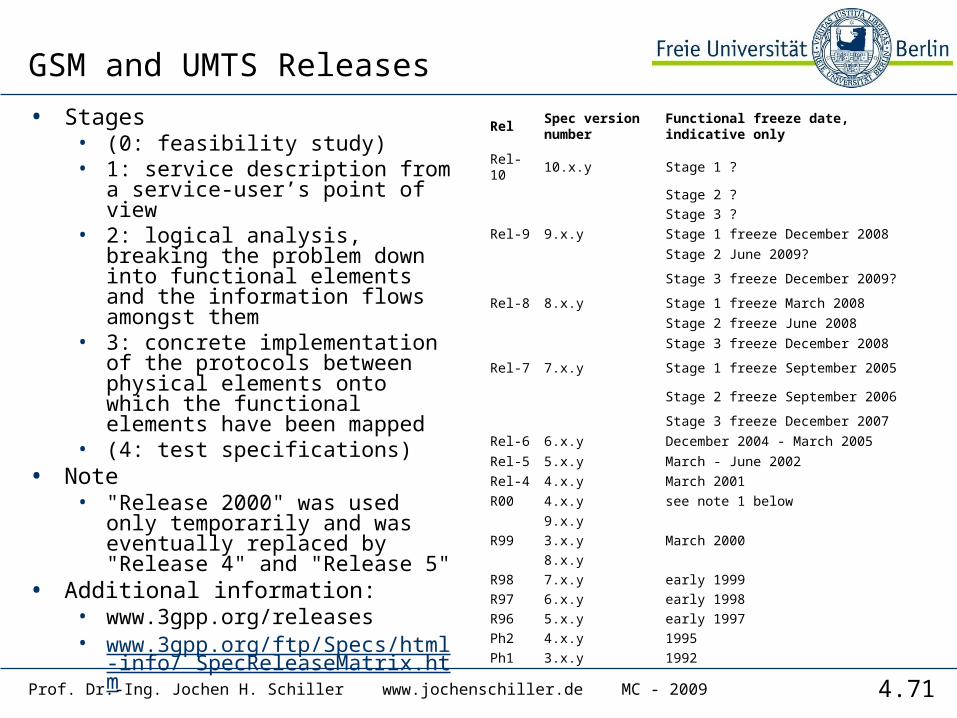
GSM and UMTS Releases
• Stages• (0: feasibility study)• 1: service description from a
service-user’s point of view• 2: logical analysis, breaking the
problem down into functional elements and the information flows amongst them
• 3: concrete implementation of the protocols between physical elements onto which the functional elements have been mapped
• (4: test specifications)• Note
• "Release 2000" was used only temporarily and was eventually replaced by "Release 4" and "Release 5"
• Additional information:• www.3gpp.org/releases• www.3gpp.org/ftp/Specs/html-inf
o/ SpecReleaseMatrix.htm
RelSpec version number
Functional freeze date, indicative only
Rel-10 10.x.y Stage 1 ?
Stage 2 ?
Stage 3 ?
Rel-9 9.x.y Stage 1 freeze December 2008
Stage 2 June 2009?
Stage 3 freeze December 2009?
Rel-8 8.x.y Stage 1 freeze March 2008
Stage 2 freeze June 2008
Stage 3 freeze December 2008
Rel-7 7.x.y Stage 1 freeze September 2005
Stage 2 freeze September 2006
Stage 3 freeze December 2007
Rel-6 6.x.y December 2004 - March 2005
Rel-5 5.x.y March - June 2002
Rel-4 4.x.y March 2001
R00 4.x.y see note 1 below
9.x.y
R99 3.x.y March 2000
8.x.y
R98 7.x.y early 1999
R97 6.x.y early 1998
R96 5.x.y early 1997
Ph2 4.x.y 1995
Ph1 3.x.y 1992
Prof. Dr.-Ing. Jochen H. Schiller www.jochenschiller.de MC - 2009
4.72Prof. Dr.-Ing. Jochen H. Schiller www.jochenschiller.de MC - 2009
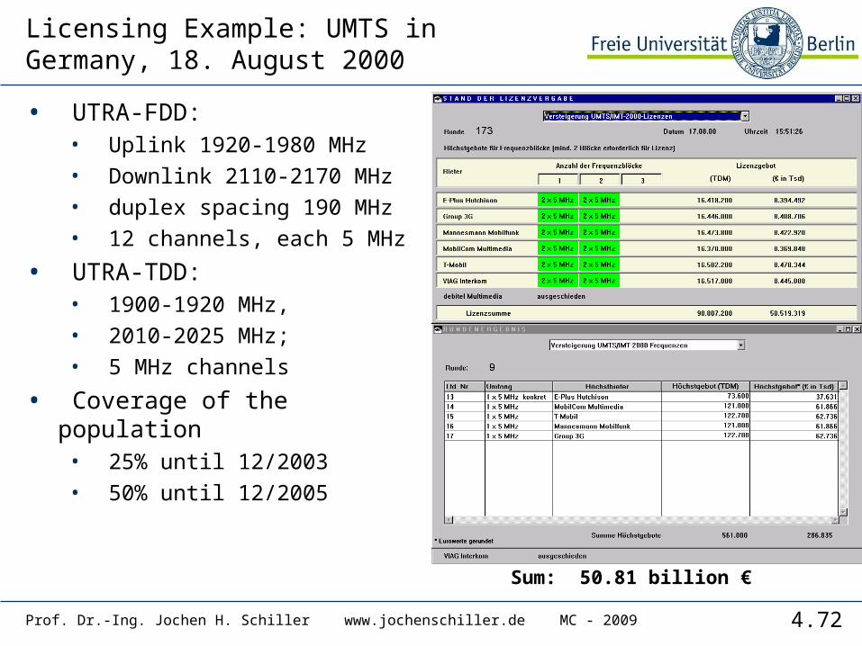
Licensing Example: UMTS in Germany, 18. August 2000
• UTRA-FDD: • Uplink 1920-1980 MHz• Downlink 2110-2170 MHz• duplex spacing 190 MHz • 12 channels, each 5 MHz
• UTRA-TDD: • 1900-1920 MHz, • 2010-2025 MHz; • 5 MHz channels
• Coverage of the population • 25% until 12/2003• 50% until 12/2005
Sum: 50.81 billion €

4.73Prof. Dr.-Ing. Jochen H. Schiller www.jochenschiller.de MC - 2009
UMTS architecture(Release 99 used here!)
UTRANUE CN
IuUu
• UTRAN (UTRA Network)• Cell level mobility• Radio Network Subsystem (RNS)• Encapsulation of all radio specific tasks
• UE (User Equipment)
• CN (Core Network)• Inter system handover• Location management if there is no dedicated connection
between UE and UTRAN
4.74Prof. Dr.-Ing. Jochen H. Schiller www.jochenschiller.de MC - 2009
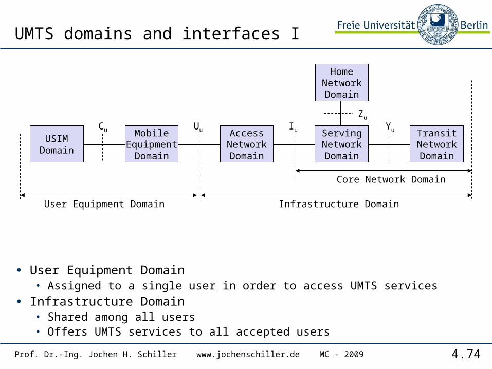
UMTS domains and interfaces I
• User Equipment Domain• Assigned to a single user in order to access UMTS services
• Infrastructure Domain• Shared among all users• Offers UMTS services to all accepted users
USIMDomain
MobileEquipment
Domain
AccessNetworkDomain
ServingNetworkDomain
TransitNetworkDomain
HomeNetworkDomain
Cu Uu Iu
User Equipment Domain
Zu
Yu
Core Network Domain
Infrastructure Domain
4.75Prof. Dr.-Ing. Jochen H. Schiller www.jochenschiller.de MC - 2009
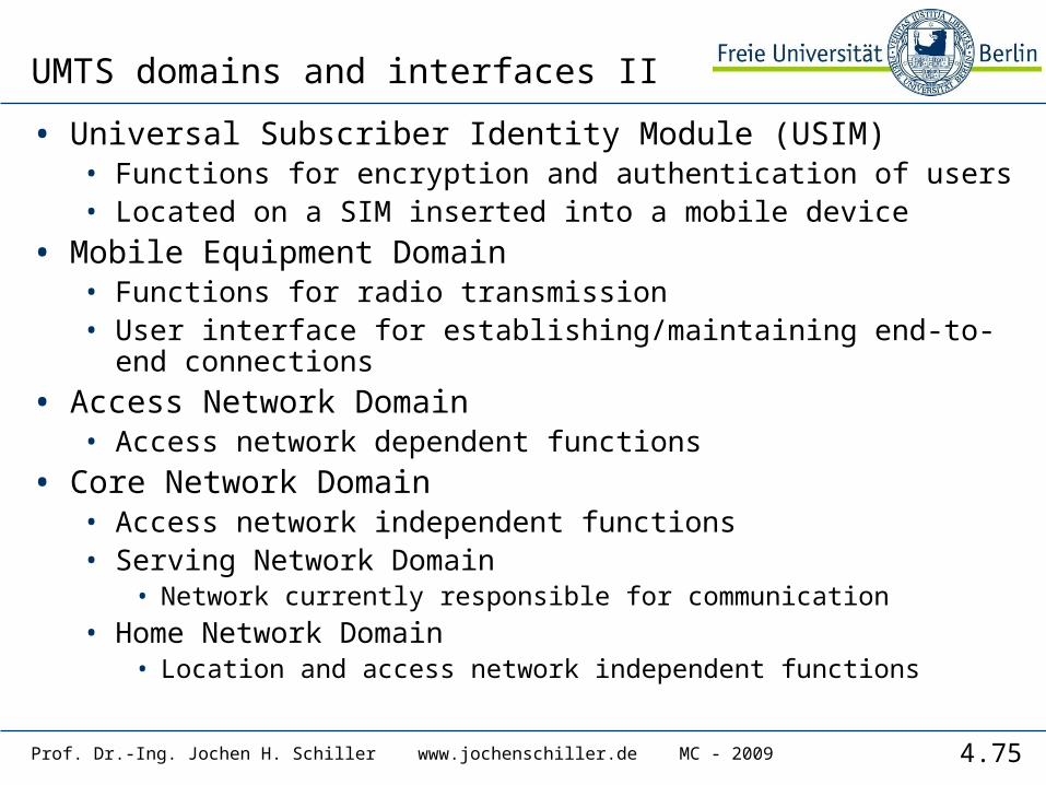
UMTS domains and interfaces II
• Universal Subscriber Identity Module (USIM)• Functions for encryption and authentication of users• Located on a SIM inserted into a mobile device
• Mobile Equipment Domain• Functions for radio transmission • User interface for establishing/maintaining end-to-end
connections
• Access Network Domain• Access network dependent functions
• Core Network Domain• Access network independent functions• Serving Network Domain
• Network currently responsible for communication• Home Network Domain
• Location and access network independent functions

4.76Prof. Dr.-Ing. Jochen H. Schiller www.jochenschiller.de MC - 2009
Spreading and scrambling of user data
• Constant chipping rate of 3.84 Mchip/s• Different user data rates supported via different spreading factors
• higher data rate: less chips per bit and vice versa
• User separation via unique, quasi orthogonal scrambling codes• users are not separated via orthogonal spreading codes• much simpler management of codes: each station can use the same
orthogonal spreading codes• precise synchronization not necessary as the scrambling codes stay quasi-
orthogonal
data1 data2 data3
scramblingcode1
spr.code3
spr.code2
spr.code1
data4 data5
scramblingcode2
spr.code4
spr.code1
sender1 sender2
4.77Prof. Dr.-Ing. Jochen H. Schiller www.jochenschiller.de MC - 2009
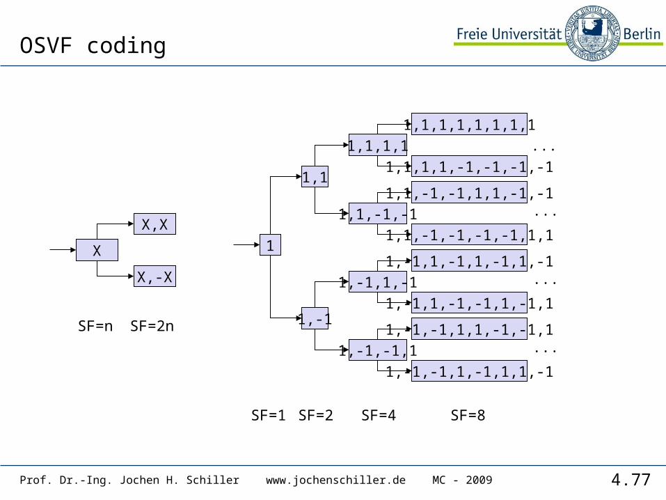
OSVF coding
1
1,1
1,-1
1,1,1,1
1,1,-1,-1
X
X,X
X,-X 1,-1,1,-1
1,-1,-1,1
1,-1,-1,1,1,-1,-1,1
1,-1,-1,1,-1,1,1,-1
1,-1,1,-1,1,-1,1,-1
1,-1,1,-1,-1,1,-1,1
1,1,-1,-1,1,1,-1,-1
1,1,-1,-1,-1,-1,1,1
1,1,1,1,1,1,1,1
1,1,1,1,-1,-1,-1,-1
SF=1 SF=2 SF=4 SF=8
SF=n SF=2n
...
...
...
...
4.78Prof. Dr.-Ing. Jochen H. Schiller www.jochenschiller.de MC - 2009
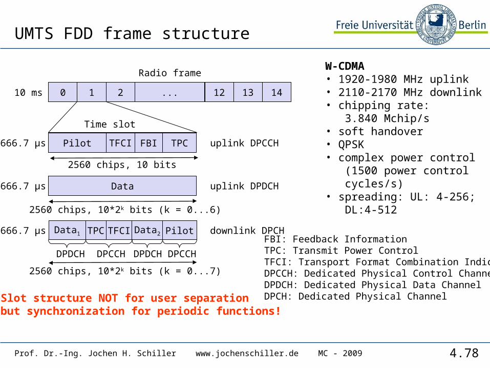
UMTS FDD frame structure
W-CDMA• 1920-1980 MHz uplink• 2110-2170 MHz downlink• chipping rate: 3.840 Mchip/s• soft handover• QPSK• complex power control (1500 power control cycles/s)• spreading: UL: 4-256; DL:4-512
0 1 2 12 13 14...
Radio frame
Pilot FBI TPC
Time slot
666.7 µs
10 ms
Data
Data1
uplink DPDCH
uplink DPCCH
downlink DPCHTPC TFCI Pilot
666.7 µs
666.7 µs
DPCCH DPDCH
2560 chips, 10 bits
2560 chips, 10*2k bits (k = 0...6)
TFCI
2560 chips, 10*2k bits (k = 0...7)
Data2
DPDCH DPCCH
FBI: Feedback InformationTPC: Transmit Power ControlTFCI: Transport Format Combination IndicatorDPCCH: Dedicated Physical Control ChannelDPDCH: Dedicated Physical Data ChannelDPCH: Dedicated Physical ChannelSlot structure NOT for user separation
but synchronization for periodic functions!

4.79Prof. Dr.-Ing. Jochen H. Schiller www.jochenschiller.de MC - 2009
Typical UTRA-FDD uplink data rates
User data rate [kbit/s]12.2 (voice)
64 144 384
DPDCH [kbit/s] 60 240 480 960
DPCCH [kbit/s] 15 15 15 15
Spreading 64 16 8 4
4.80Prof. Dr.-Ing. Jochen H. Schiller www.jochenschiller.de MC - 2009
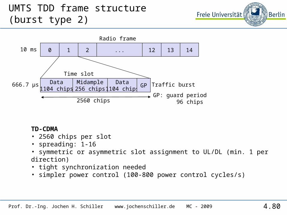
UMTS TDD frame structure(burst type 2)
TD-CDMA• 2560 chips per slot• spreading: 1-16• symmetric or asymmetric slot assignment to UL/DL (min. 1 per direction)• tight synchronization needed• simpler power control (100-800 power control cycles/s)
0 1 2 12 13 14...
Radio frame
Data1104 chips
Midample256 chips
Data1104 chips
Time slot
666.7 µs
10 ms
Traffic burstGP
GP: guard period 96 chips2560 chips
4.81Prof. Dr.-Ing. Jochen H. Schiller www.jochenschiller.de MC - 2009
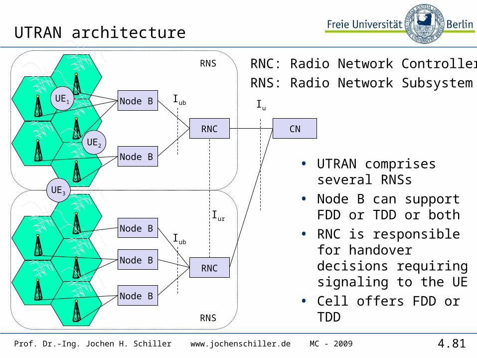
UTRAN architecture
• UTRAN comprises several RNSs
• Node B can support FDD or TDD or both
• RNC is responsible for handover decisions requiring signaling to the UE
• Cell offers FDD or TDD
RNC: Radio Network ControllerRNS: Radio Network Subsystem
Node B
Node B
RNC
Iub
Node B
UE1
RNS
CN
Node B
Node B
RNC
Iub
Node B
RNS
Iur
Node B
UE2
UE3
Iu
4.82Prof. Dr.-Ing. Jochen H. Schiller www.jochenschiller.de MC - 2009
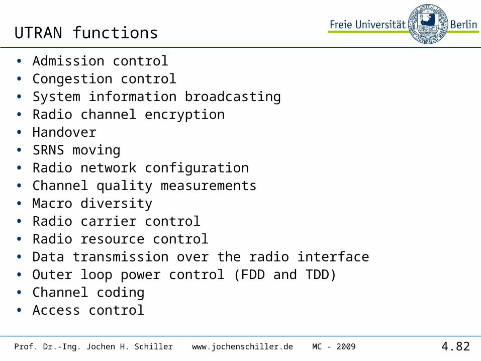
UTRAN functions
• Admission control• Congestion control• System information broadcasting• Radio channel encryption• Handover• SRNS moving• Radio network configuration• Channel quality measurements• Macro diversity• Radio carrier control• Radio resource control• Data transmission over the radio interface• Outer loop power control (FDD and TDD)• Channel coding• Access control
4.83Prof. Dr.-Ing. Jochen H. Schiller www.jochenschiller.de MC - 2009
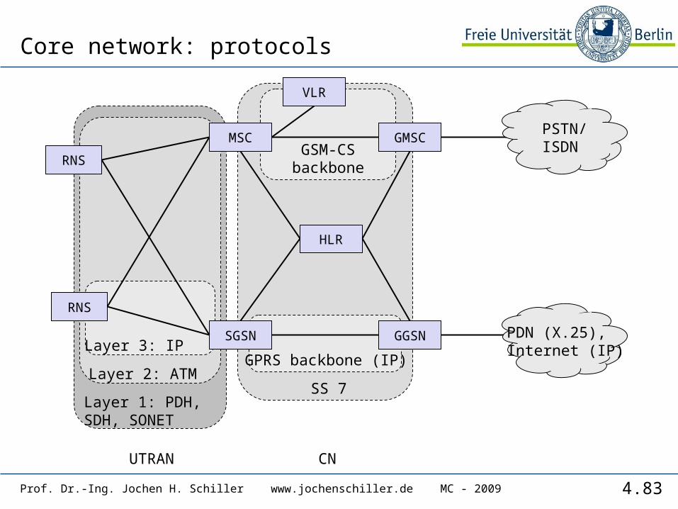
Core network: protocols
MSC
RNS
SGSN GGSN
GMSC
HLR
VLR
RNS
Layer 1: PDH, SDH, SONET
Layer 2: ATM
Layer 3: IPGPRS backbone (IP)
SS 7
GSM-CSbackbone
PSTN/ISDN
PDN (X.25),Internet (IP)
UTRAN CN
4.84Prof. Dr.-Ing. Jochen H. Schiller www.jochenschiller.de MC - 2009
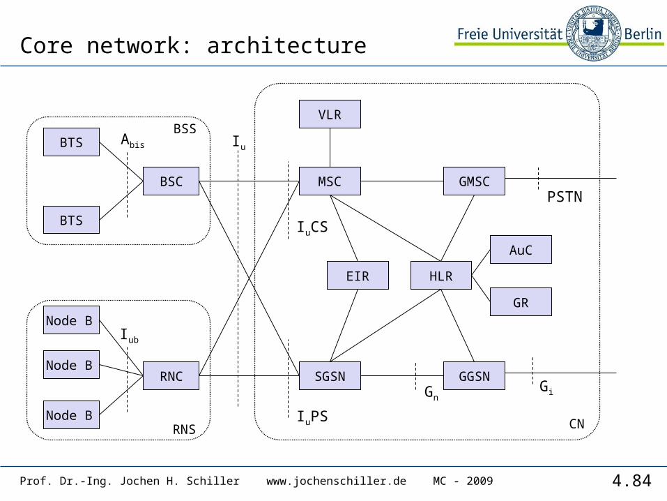
Core network: architecture
BTS
Node B
BSC
Abis
BTS
BSS
MSC
Node B
Node B
RNC
Iub
Node BRNS
Node BSGSN GGSN
GMSC
HLR
VLR
IuPS
IuCS
Iu
CN
EIR
GnGi
PSTN
AuC
GR
4.85Prof. Dr.-Ing. Jochen H. Schiller www.jochenschiller.de MC - 2009
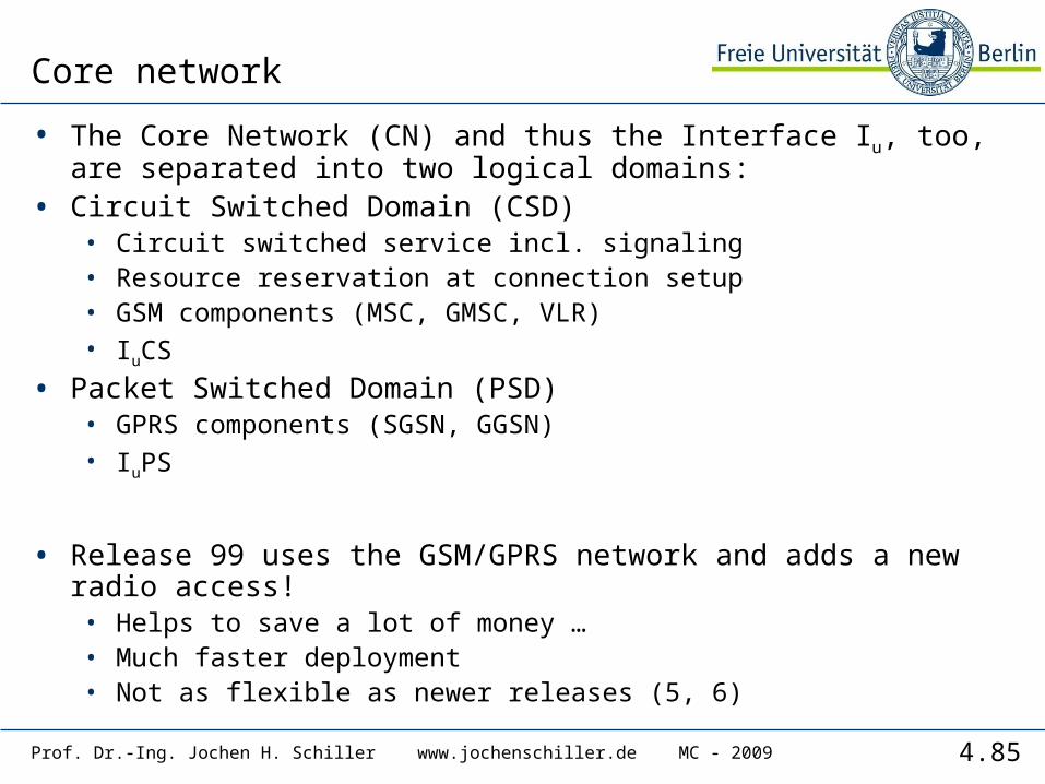
Core network
• The Core Network (CN) and thus the Interface Iu, too, are separated into two logical domains:
• Circuit Switched Domain (CSD)• Circuit switched service incl. signaling• Resource reservation at connection setup• GSM components (MSC, GMSC, VLR)• IuCS
• Packet Switched Domain (PSD)• GPRS components (SGSN, GGSN)• IuPS
• Release 99 uses the GSM/GPRS network and adds a new radio access!• Helps to save a lot of money …• Much faster deployment• Not as flexible as newer releases (5, 6)

4.86Prof. Dr.-Ing. Jochen H. Schiller www.jochenschiller.de MC - 2009
UMTS protocol stacks (user plane)
apps. &protocols
MAC
radio
MAC
radio
RLC SAR
UuIuCSUE UTRAN 3G
MSC
RLC
AAL2
ATM
AAL2
ATM
SAR
apps. &protocols
MAC
radio
MAC
radio
PDCP GTP
Uu IuPSUE UTRAN 3GSGSN
RLC
AAL5
ATM
AAL5
ATM
UDP/IP
PDCP
RLC UDP/IP UDP/IP
Gn
GTP GTP
L2
L1
UDP/IP
L2
L1
GTP
3GGGSN
IP, PPP,…
IP, PPP,…
IP tunnel
Circuitswitched
Packetswitched

4.87Prof. Dr.-Ing. Jochen H. Schiller www.jochenschiller.de MC - 2009
Support of mobility: macro diversity
• Multicasting of data via several physical channels• Enables soft handover• FDD mode only
• Uplink• simultaneous reception of
UE data at several Node Bs• Reconstruction of data at
Node B, SRNC or DRNC
• Downlink• Simultaneous transmission
of data via different cells• Different spreading codes
in different cells
CNNode B RNC
Node BUE
4.88Prof. Dr.-Ing. Jochen H. Schiller www.jochenschiller.de MC - 2009
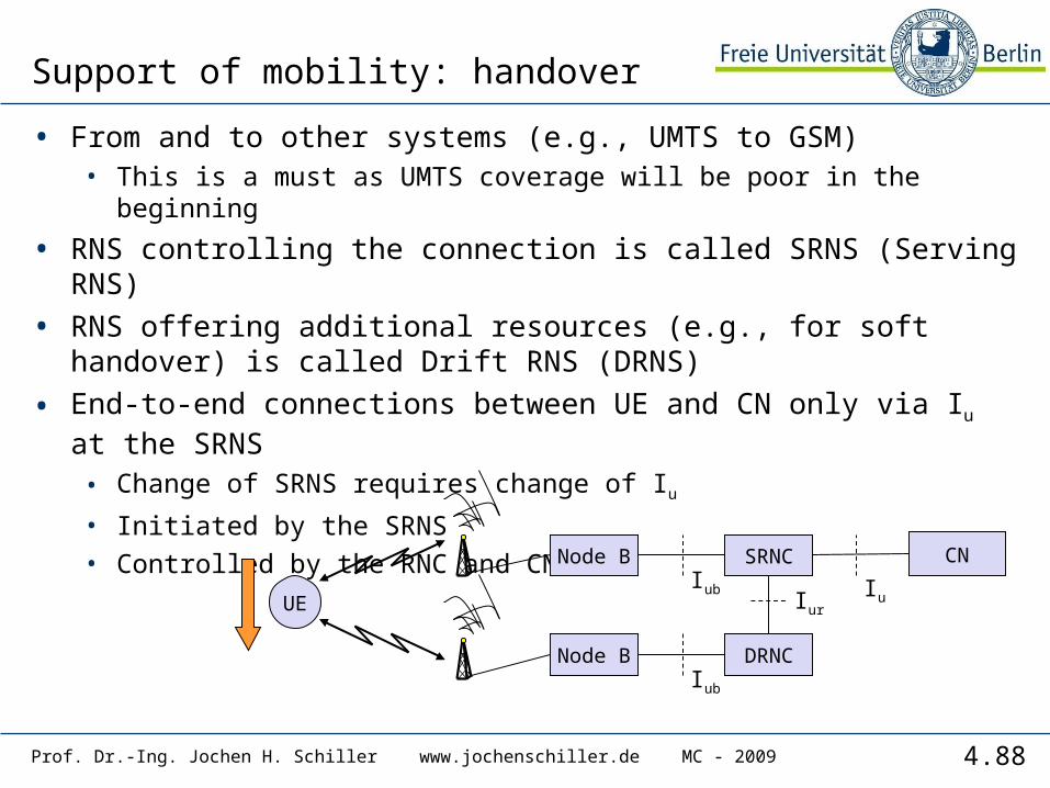
Support of mobility: handover
• From and to other systems (e.g., UMTS to GSM)• This is a must as UMTS coverage will be poor in the beginning
• RNS controlling the connection is called SRNS (Serving RNS)
• RNS offering additional resources (e.g., for soft handover) is called Drift RNS (DRNS)
• End-to-end connections between UE and CN only via Iu at the SRNS• Change of SRNS requires change of Iu
• Initiated by the SRNS• Controlled by the RNC and CN
SRNC
UE
DRNC
Iur
CN
Iu
Node BIub
Node BIub
4.89Prof. Dr.-Ing. Jochen H. Schiller www.jochenschiller.de MC - 2009
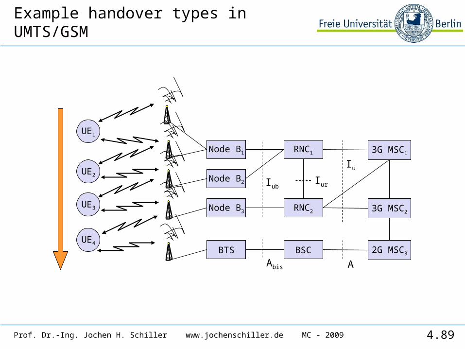
Example handover types in UMTS/GSM
RNC1
UE1
RNC2
Iur
3G MSC1
Iu
Node B1
IubNode B2
Node B3 3G MSC2
BSCBTS 2G MSC3
AAbis
UE2
UE3
UE4
4.90Prof. Dr.-Ing. Jochen H. Schiller www.jochenschiller.de MC - 2009
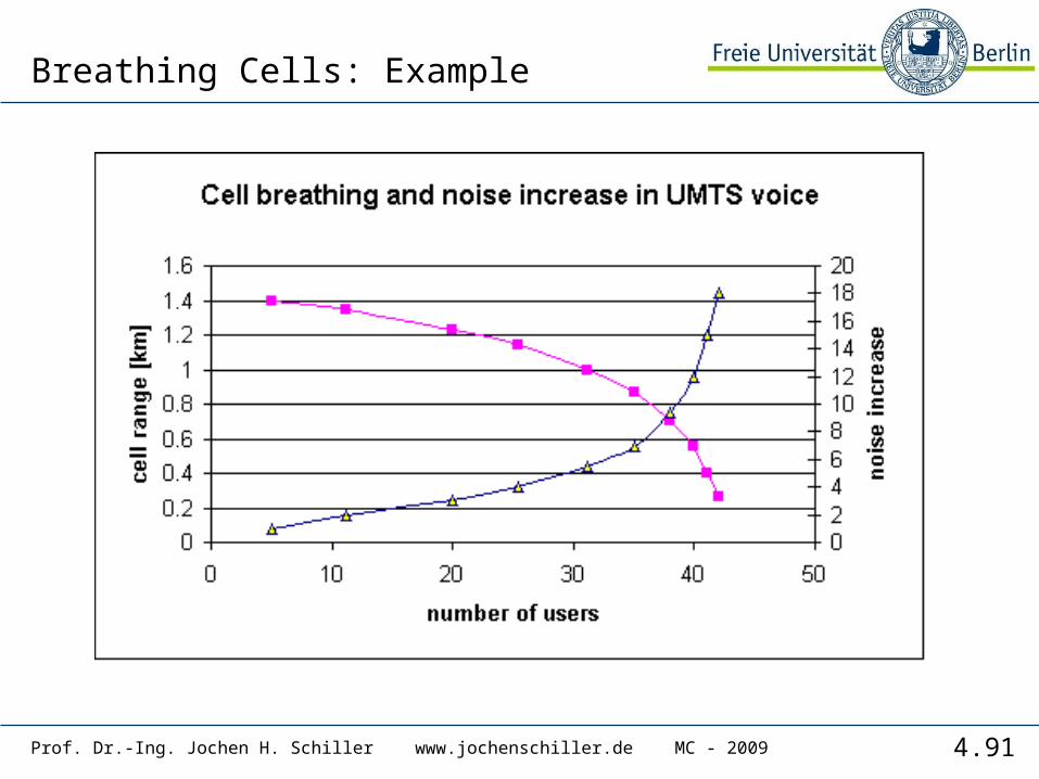
Breathing Cells
• GSM• Mobile device gets exclusive signal from the base station • Number of devices in a cell does not influence cell size
• UMTS• Cell size is closely correlated to the cell capacity• Signal-to-nose ratio determines cell capacity• Noise is generated by interference from
• other cells• other users of the same cell
• Interference increases noise level• Devices at the edge of a cell cannot further increase their output
power (max. power limit) and thus drop out of the cell no more communication possible
• Limitation of the max. number of users within a cell required
• Cell breathing complicates network planning
4.91Prof. Dr.-Ing. Jochen H. Schiller www.jochenschiller.de MC - 2009
Breathing Cells: Example
4.92Prof. Dr.-Ing. Jochen H. Schiller www.jochenschiller.de MC - 2009
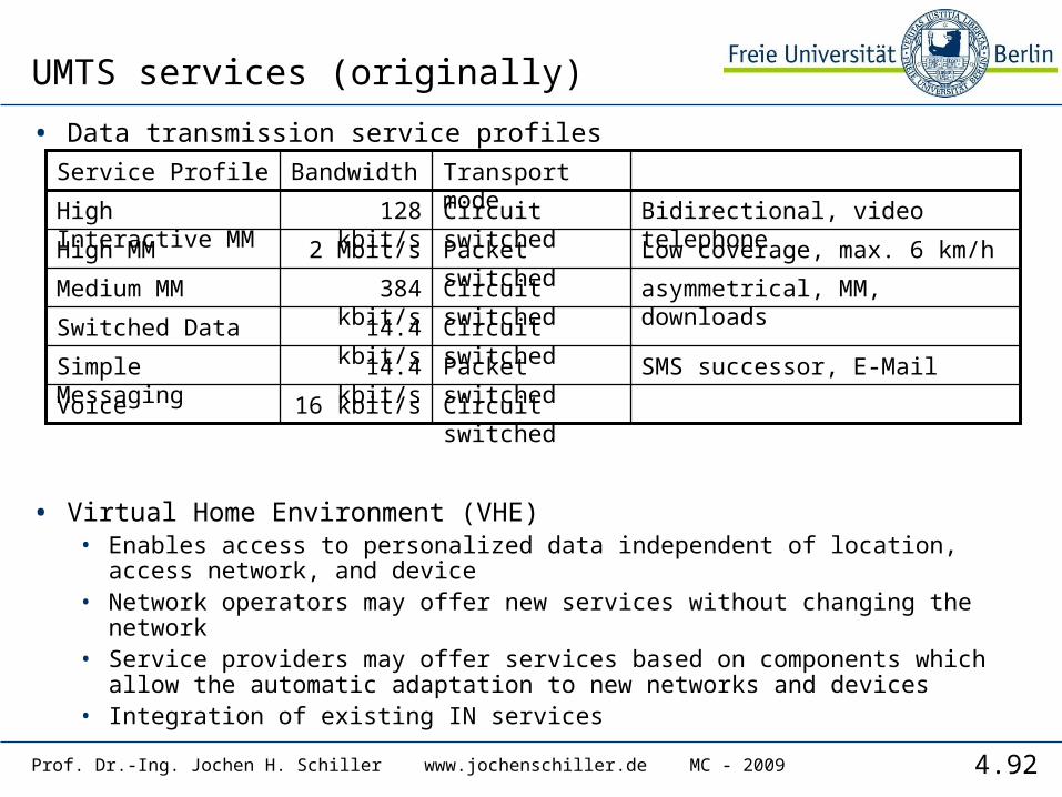
UMTS services (originally)
• Data transmission service profiles
• Virtual Home Environment (VHE)• Enables access to personalized data independent of location, access
network, and device• Network operators may offer new services without changing the
network• Service providers may offer services based on components which
allow the automatic adaptation to new networks and devices• Integration of existing IN services
Circuit switched16 kbit/sVoice
SMS successor, E-MailPacket switched14.4 kbit/sSimple Messaging
Circuit switched14.4 kbit/sSwitched Data
asymmetrical, MM, downloadsCircuit switched384 kbit/sMedium MM
Low coverage, max. 6 km/hPacket switched2 Mbit/sHigh MM
Bidirectional, video telephoneCircuit switched128 kbit/sHigh Interactive MM
Transport modeBandwidthService Profile
4.93Prof. Dr.-Ing. Jochen H. Schiller www.jochenschiller.de MC - 2009
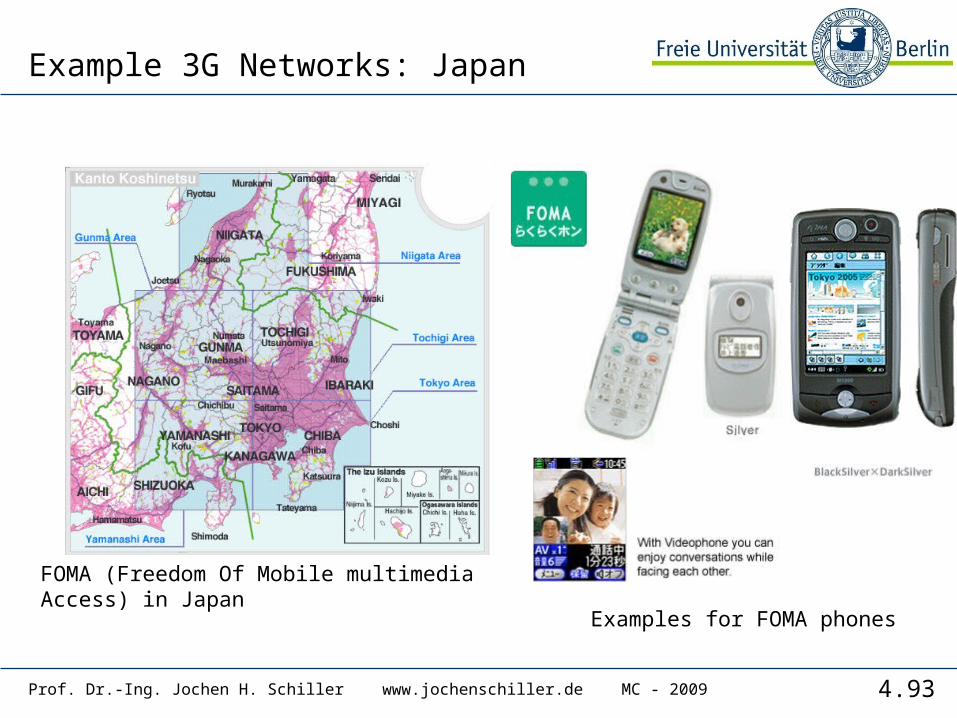
Example 3G Networks: Japan
FOMA (Freedom Of Mobile multimediaAccess) in Japan
Examples for FOMA phones
4.94Prof. Dr.-Ing. Jochen H. Schiller www.jochenschiller.de MC - 2009
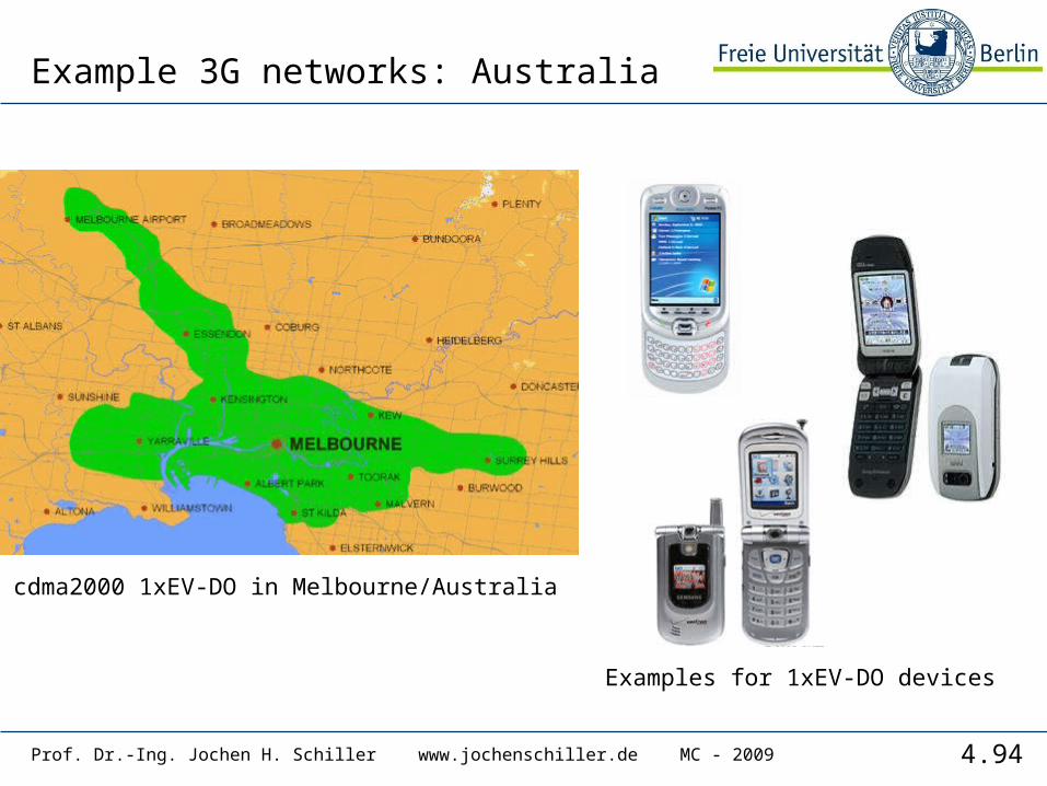
Example 3G networks: Australia
cdma2000 1xEV-DO in Melbourne/Australia
Examples for 1xEV-DO devices
4.95Prof. Dr.-Ing. Jochen H. Schiller www.jochenschiller.de MC - 2009
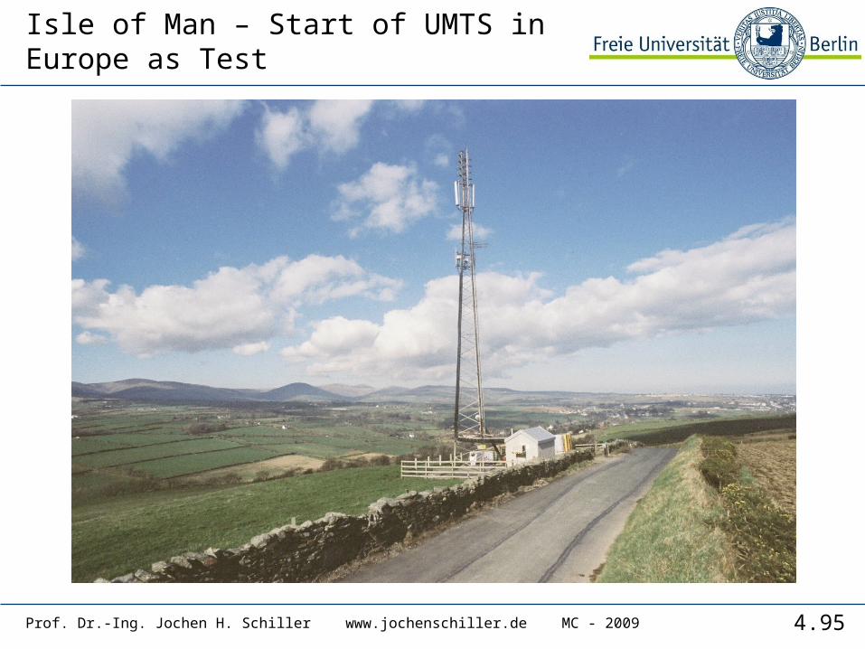
Isle of Man – Start of UMTS in Europe as Test
4.96Prof. Dr.-Ing. Jochen H. Schiller www.jochenschiller.de MC - 2009
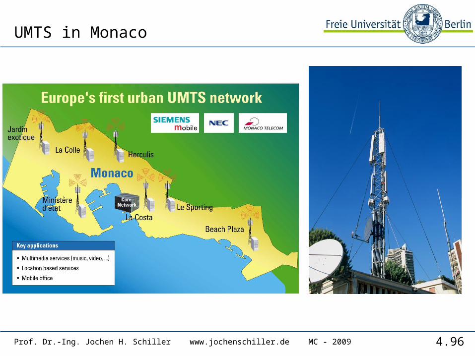
UMTS in Monaco
4.97Prof. Dr.-Ing. Jochen H. Schiller www.jochenschiller.de MC - 2009
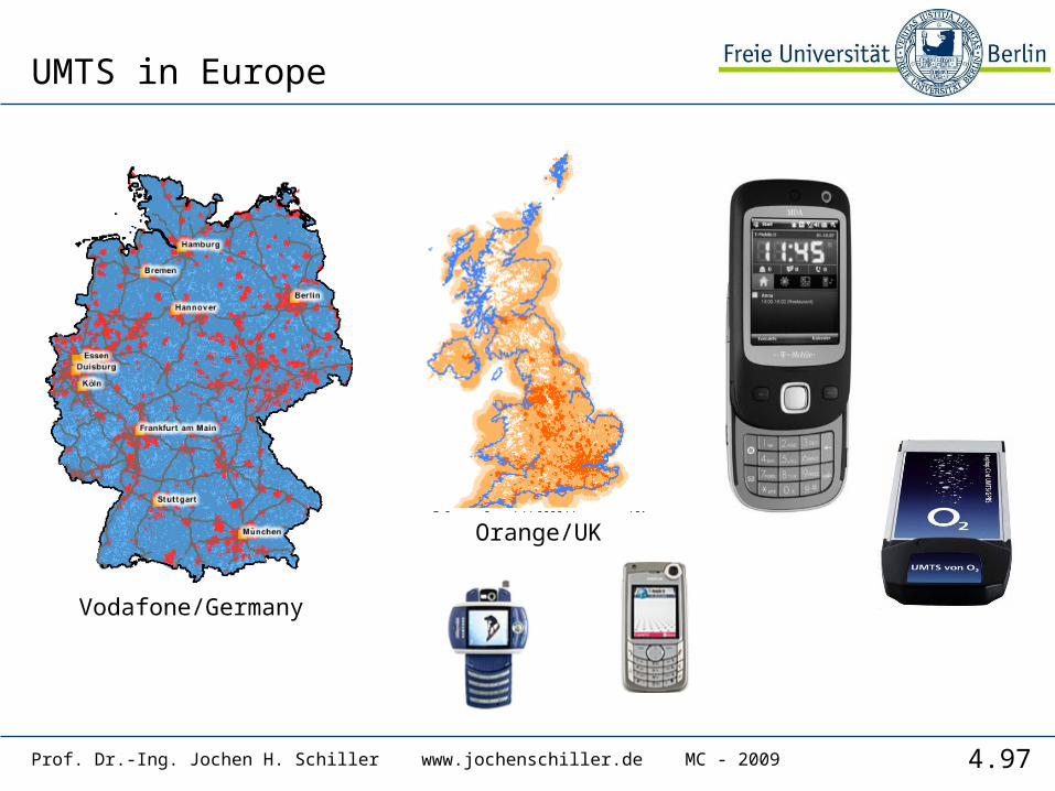
UMTS in Europe
Vodafone/Germany
Orange/UK
4.98Prof. Dr.-Ing. Jochen H. Schiller www.jochenschiller.de MC - 2009
Some current enhancements
• GSM• EMS/MMS
• EMS: 760 characters possible by chaining SMS, animated icons, ring tones, was soon replaced by MMS (or simply skipped)
• MMS: transmission of images, video clips, audio• see WAP 2.0 / chapter 10
• EDGE (Enhanced Data Rates for Global [was: GSM] Evolution)• 8-PSK instead of GMSK, up to 384 kbit/s• new modulation and coding schemes for GPRS EGPRS
• MCS-1 to MCS-4 uses GMSK at rates 8.8/11.2/14.8/17.6 kbit/s• MCS-5 to MCS-9 uses 8-PSK at rates 22.4/29.6/44.8/54.4/59.2 kbit/s
• UMTS• HSDPA (High-Speed Downlink Packet Access)
• initially up to 10 Mbit/s for the downlink, later > 20 Mbit/s using MIMO- (Multiple Input Multiple Output-) antennas
• can use 16-QAM instead of QPSK (ideally > 13 Mbit/s)• user rates e.g. 3.6 or 7.2 Mbit/s
• HSUPA (High-Speed Uplink Packet Access)• initially up to 5 Mbit/s for the uplink• user rates e.g. 1.45 Mbit/s


