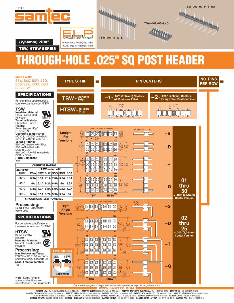
(2,54mm) .100"
TSW, HTSW SERIES
TSW–116–11–G–S
TSW–108–05–L–Q
TSW–209–09–F–S–RA
WWW.SAMTEC.COM
TSW Standard Strip=
NO. PINSPER ROW
Mates with:SSW, SSQ, ESW, ESQ, BCS, BSW, IDSD, IDSS, CES, SLW
TYPE STRIP PIN CENTERS
StraightPin
Versions
– S
– D
– T
– Q
– S
– D
– T
– Q
Note: Some lengths, styles and options are non-standard, non-returnable.
01 thru 50
= .100" (2,54mm) Center Version
02 thru 25
= .200"(5,08mm) Center Version
(2,54).100
(2,54) .100 x No. of Positions
(2,54).100
(2,54).100
(5,08).200
(7,62).300
0150
10002
990103
148
150
01
(5,08).200
(2,54).100
(5,02).198
(2,48).098
150
148
(7,62).300
03
01
(7,56).298
(5,08).200
(7,56).298
TSW HTSW
(2,54).100
(2,54) .100 x No. of Positions
(3,02).119 (1,78)
.070
(5,56).219
50
01
02100
01 99
TSW HTSW
(5,08).200
(2,54).100
(8,12).320
(1,78).070
(3,09).120
(1,78).070
(6,10).240
(1,78).070
01 148
03 150
01 148
03 150
(2,54).100
(1,78).070
(1,78).070
(2,54).100
(8,12).320
(1,78).070
(8,10).319
(5,08).200
(1,78).070
(8,10).319
RightAngle
Versions
HTSW= Hi-Temp Strip
F-210-1
(2,54).100
(5,08).200
–1= .100" (2,54mm) Centers, All Positions Filled – 2= .200" (5,08mm) Centers,
Every Other Position FilledFor complete specifi cations see www.samtec.com?TSW
TSWInsulator Material: Black Glass FilledPolyesterTerminal Material:Phosphor BronzePlating: Au or Sn over 50µ" (1,27µm) NiOperating Temp Range:-55°C to +125°C with Gold-55°C to +105°C with TinVoltage Rating:550 VAC mated with SSW; 500 VAC mated with BCS or ESQ;450 VAC -RA/-RE mated with BCS or SSMRoHS Compliant: Yes
Processing:Lead–Free Solderable: Wave Only
SPECIFICATIONS
For complete specifi cations see www.samtec.com?HTSW
HTSW Same as TSW except: Insulator Material: Natural Liquid Crystal Polymer
Processing:Max Processing Temp:230°C for 30 to 60 seconds, or 260°C for 20 seconds 3xLead–Free Solderable:Yes
SPECIFICATIONS
HORIZONTAL
APPLICATIONS
BCS TSW
AMBIENTTEMP
20°C
40°C
60°C
95°C
6.9A
6A
5.3A
3.5A
CURRENT RATINGTSW mated with
ESW SSW SLW SSQ SSM BCS
6.9A
6.1A
5.3A
3.5A
7.1A
6.2A
5.8A
3.7A
7.6A
6.9A
5.9A
3.9A
6.9A
6A
5.3A
3.5A
5.9A
5.2A
4.7A
3A
6 POSITIONS (2x3) POWERED
EXTENDED LIFE PRODUCT
10 Year Mixed Flowing Gas (MFG)
TM
Call Samtec for maximum cycles
THROUGH-HOLE .025" SQ POST HEADER
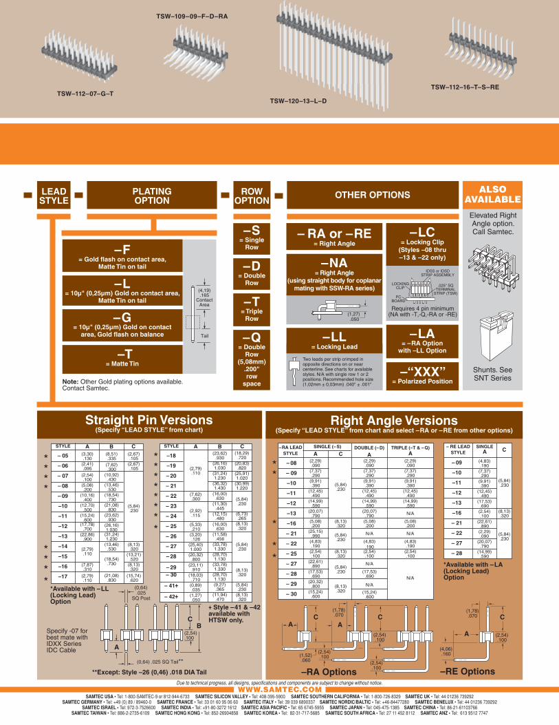
TSW–112–07–G–T
TSW–109–09–F–D–RA
TSW–120–13–L–D
TSW–112–16–T–S–RE
WWW.SAMTEC.COM
Two leads per strip crimped in opposite directions on or near centerline. See charts for available styles. N/A with single row 1 or 2 positions. Recommended hole size (1,02mm ± 0,03mm) .040" ± .001"
OTHER OPTIONS
(2,29) .090
(7,37) .290
(9,91) .390
(12,45) .490
(14,99) .590
(20,07) .790
(5,08).200
N/A
(4,83) .190
(2,54).100
N/A
(17,53).690
N/A
(15,24).600
Straight Pin Versions(Specify “LEAD STYLE” from chart)
Right Angle Versions(Specify “LEAD STYLE” from chart and select –RA or –RE from other options)
TRIPLE (–T & – Q)A
– RE LEADSTYLE
(4,83).190
(7,37).290
(9,91).390
(12,45).490
(17,53).690
(2,54).100
(22,61).890
(2,29).090
(20,07).790
(14,99).590
– 09
–10
–11
–12
–13
–16
– 21
– 22
– 27
– 28
SINGLEA
–RA LEADSTYLE
– 08
– 09
–10
–11
–12
–13
–16
– 21
– 22
– 25
– 27
– 28
– 29
– 30
(2,29).090
(7,37).290
(9,91).390
(12,45).490
(14,99).590
(20,07).790
(5,08).200
(25,15).990
(4,83).190
(2,54).100
(22,61).890
(17,53).690
(20,32).800
(15,24).600
A
(5,84).230
(8,13).320
(5,84).230
(8,13).320
(5,84).230
(8,13).320
CSINGLE (– S) DOUBLE (– D)
A(2,29) .090
(7,37) .290
(9,91) .390
(12,45) .490
(14,99) .590
N/A
(5,08).200
N/A
(4,83) .190
(2,54) .100
N/A
C
– 05
– 06
– 07
– 08
– 09
–10
–11
–12
–13
–14
–15
–16
–17
BSTYLE A(8,51).335
(7,62).300
(10,92).430
(13,46).530
(18,54).730
(21,08).830
(23,62).930
(26,16)1.030
(31,24)1.230
(13,46).530
(18,54).730
(21,08).830
(2,67).105
(2,67).105
(5,84).230
(8,13).320
(13,21).520
(8,13).320
(15,74).620
(3,30).130
(2,41).095
(2,54).100
(5,08).200
(10,16).400
(12,70).500
(15,24).600
(17,78).700
(22,86).900
(2,79).110
(7,87).310
(2,79).110
*Available with –LL (Locking Lead) Option
**Except: Style –26 (0,46) .018 DIA Tail
LEADSTYLE
(5,84).230
(8,13).320
(5,84).230
C
–RA Options –RE Op tions
CA A
(2,54).100
(1,78).070
(2,54).100
A (2,54).100
(1,78).070
(4,06).160
(2,54).100
(1,52).060
C C
– RA or –RE= Right Angle
PLATINGOPTION
(0,64).025
SQ Post
(2,54).100
(0,64) .025 SQ Tail**
CB
A
****
****
********
**
*
**
Specify -07 for best mate with IDXX Series IDC Cable
–F= Gold fl ash on contact area,
Matte Tin on tail
–L= 10µ" (0,25µm) Gold on contact area,
Matte Tin on tail
–G= 10µ" (0,25µm) Gold on contact
area, Gold fl ash on balance
–T= Matte Tin
–S= Single
Row
–D= Double
Row
–T= Triple
Row
–Q= Double
Row (5,08mm)
.200" row
space
ALSO AVAILABLE
Elevated Right Angle option. Call Samtec.
–18
–19
– 20
– 21
– 22
– 23
– 24
– 25
– 26
– 27
– 28
– 29– 30
– 41+
– 42+
BSTYLE A C(23,62)
.930(26,16)1.030
(31,24)1.230
(36,32)1.430
(16,00).630
(11,30).445
(12,15).480
(16,00).630
(11,58).456
(33,78)1.330
(28,70)1.130
(33,78)1.330
(28,70)1.130(9,27).365
(11,94).470
(2,79).110
(7,62).300
(2,92).115
(5,33).210
(3,20).126
(25,40)1.000
(20,32).800
(23,11).910
(18,03).710
(0,89).035
(1,27).050
(18,29).720
(20,83).820
(25,91)1.020
(30,99)1.220
(5,84).230
(6,73).265
(8,13).320
(5,84).230
(8,13).320
(5,84).230
(8,13).320
–“XXX”= Polarized Position
+ Style –41 & –42 available with HTSW only.
–LC= Locking Clip
(Styles –08 thru –13 & –22 only)
LOCKINGCLIP
PCBOARD
IDSS or IDSDSTRIP ASSEMBLY
.025" SQTERMINAL
STRIP (TSW)
Requires 4 pin minimum(NA with -T,-Q,-RA or -RE)
*Available with –LA (Locking Lead) Option
Shunts. See SNT Series
–LA= –RA Option
with –LL Option
ROWOPTION
Note: Other Gold plating options available.Contact Samtec.
(4,19).165
ContactArea
Tail –LL= Locking Lead
–NA= Right Angle
(using straight body for coplanar mating with SSW-RA series)
(1,27) .050


